i f0x 4765 incependence street
TRANSCRIPT
,J ,
*.
IF M FOX & ASSOCIATES. INC.
:. F0X Consulting Engineers and Geolog. ts4765 INCEPENDENCE STREET'
is WHEAT RIDGE. COLORADO 80033J (303) 424-5578 - FMFOX
;
i\
( '
4
4
h
i.h
i
3:.
['
GE0TECHfilCAL IfiVESTIGATIO.*1'
FOR THE PROPCSED SURFACE FACILITIESI AP.IZONA PL'3LIC SERVICE
PETERS 011 PROJECT,
| CONVERSE COUtlTY, UY0i'It;Gi
Prepcred for
. f;uclear Assurance Corporationfi;
,
:
1
.
4
Job i!o. 1-1362 46C0February 29, 19SO
1l
8110020076 8109:1PDR ADOCK 04008771' ,
I C PDR ALBLCUERCUE * DENVER e PHOENIX
|'
. _ _ -. _ _ -. - _ _ - ___ _.
$ '!
'.
$'
1
:i
:TAPLE OF C0flTEllTS,i
1-
i*
'
;,
4 GEriERAL Page 1i
*.
14 SITE C0f!DITI0f45 Af;D PROPOSED C0f1STRUCT!0N3
2FIELD AtlD LABORATORY IflVESTIGATI0fl5
3j Evaporation Ponds4Process Area' -
SLeach Field
f DESIC-N AflALYSIS AfiD CONSTRUCTION RECONNEriDATIONS5
Si'
Evaporation Pondsj? Process Area
9i Leach Field'j#; VICIfilTY MAP Figure 1i
i2TEST HOLE LOCATI0ft PLAft-
.s 3-5LOG 0F TEST H0LES'
.
GRADATION Af!ALYSIS 6-10
SWELL-CONSOLIDATION TESTS 11-12:,' COMPACTION TEST RESULTS 13-14
UtlCONFlflED COMPRESSION TEST RESULTS 15-20
h DIRECT SHEAR TEST RESULTS 21
SUMMARY OF S0ll TESTS Table I
FIELD PERMEABILITY TEST RESULIS II
PERCOLATION TEST RESULTS IIIJ
] SUGriESTED DESIGN SPECIFICATIONS FOR CON 5TRUCTIOf: OFSTRUCTURAL. FILL Appendix
'
|
,
|
t ;1
'
,. -
-
.. . _ _ . _
f .~' .'
.
.
! GENERALf
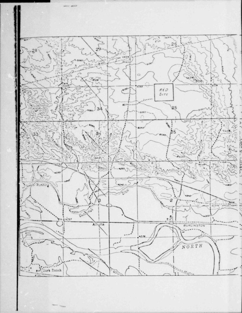
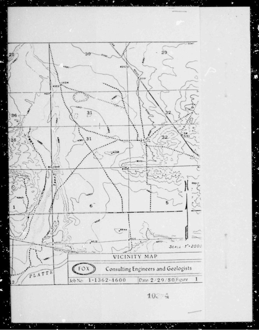
f This report presents the results of a subsoil investigation conductedo
at the site of a proposed new in-situ uranium leachina nine to be located at1
j the proposed Arizona Public Service Peterson Project, in Section 35, Town-
ship 34 North, Range 73 West, Converse County, Wyoming.
The primary purpose of this investigation was to determine the soil
conditions at the subject site, to take appropriate soil samples for deter-
mination of engineering properties for obtaining appropriate permits, and
to include recommendations which should be followed during the design and,
construction of the facility because of the soil conditions. The conclusions
and recommendations presented below are based on the data gathered during
the site investigation, on the results of laboratory te-ting and our experi-+
ence with similar soil conditions. Factual data gathered during the field,
and laboratory investigations are summarized on Figures 1 through 21, and
Tables I through III.
SITE CONDITIONS AND PROPOSED CONSTRUCTION
The site is presently vacant and is presently used for cattle grazing.
Topographically, the site slopes to the west with approximately 4 feet of
topographic relief noted across the test holes. The bedrock geology of the
site consists of sandstone and claystone shales of the Tertiary Lance forma-
tion.
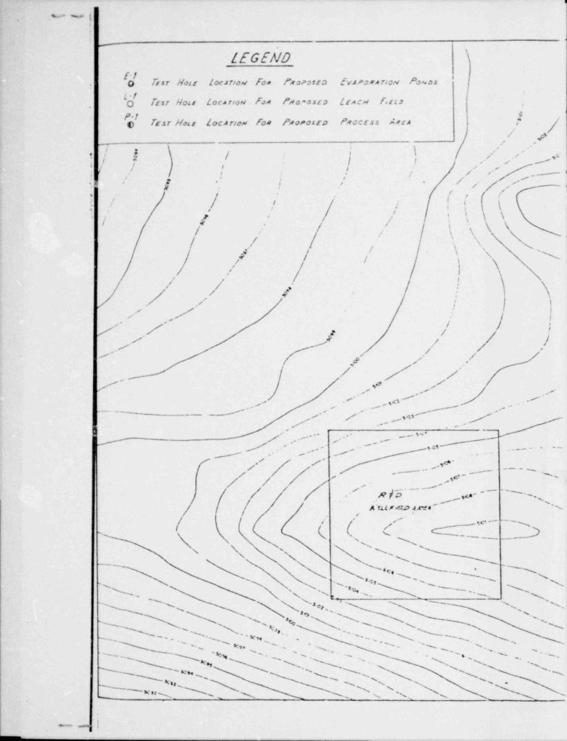
The proposed construction on the site will consist of a process area,
an associated leach field area, and two proposed evaporation ponds. The pro- |
cess area will consist of a pumpina station, storage tanks and ion exchange |
|
columns. Present plans call for this equipment to '' supported on a reinforced
concrete slab on grade or an independent foundation system. Actual foundation
-1-
<
_ _
iI.i ,
.
.
.
1
i loadino conditions were unavailable at the writino of this report; however,
.
! it is our understandino that loading will be relatively light. flaximum dif-i
) ferential movement criteria has not been established; however, it is ourf
I understanding that piping systems will be utilized which can tolerate sub-
stantial movement.
( The evaporation ponds will be approximately 9 feet in depth with bot-I
tom elevations of 5,099.5 feet and 5,098.5 feet for the east and west ponds,
'. respectively. The top of the pond embankments will be at elevation 5,108.5
feet and 5,107.5 feet, respectively. This will necessitate excavation of depths
up to 8.5 feet in the natural soils, and placement cf up to 3.5 feet of embankment
fill on the upper portion of the pond embankments. The side slopes of the embank-
ments will be constructed with 3:1 slopes (horizontal to vertical), and the ponds
will be lined with a synthetic liner material. It is our understanding that it is
desired to use low permeability soils underneath the synthetic liner as an addi-
tional precaution against seepage.
The septic system leach field will be constructed to the northwest of
the proposed process area. It is Jur understanding that Ortloff flinerals
Services Corporation will design the field on the basis of percolation data
obtained during our field investigation.
FIELD AND LABORATORY INVESTIGATIONS,
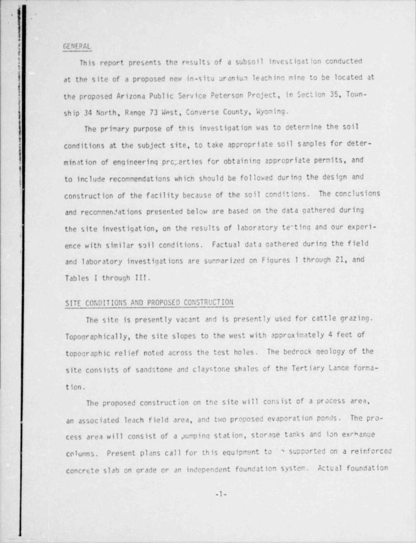
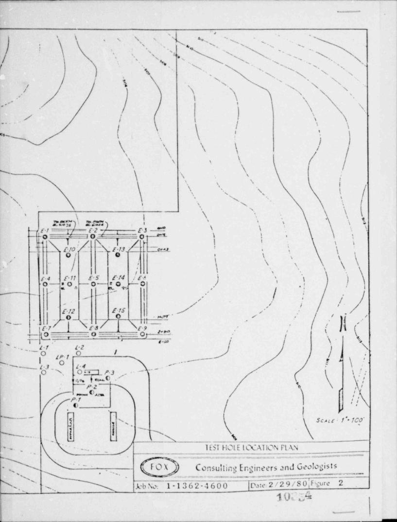
A total of 23 test holes were drilled on the site at the locations of
the proposed constructicn areas. Specifically, 15 test holes were drilled
at the location of the proposed evaporation ponds; one soil profile hole and
4 percolation holes were drilled at the location of the proposed leach f iel ..
and 3 test holes were drilled at the location of the proposed process area.
Fioure 2 shows the location of the various test holes drilled across the
-2-
,
- . . - ___ _ _ _ .- . _ _ _ _ _
.
. ,
,
ne
-- vi subsoll conditions for the test holes are shoan on Figures-
.
:n 5. At periodic intr.rvals, sampling was conducted in the test holes;
-
q .c to etrieve sar"Ples for the subsequent laboratory investigation.
m ples were returned to our Denver laboratories for further inspec-*
mo testing. The results of the laboratory investigation are shown on.
,
Y - .:ures 6 through 21 and Table I.*^
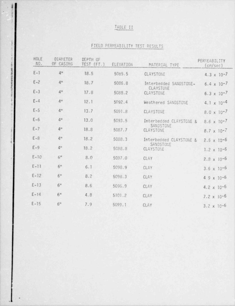
In addition to tt.e field soil investigation, test holes E-1 through E-15'' ere cased with 4 or 6 inch diameter PVC p;, e for subsequent in-situ field
'
,[ rerreability testing. The results of this testing is shown on Table II.,
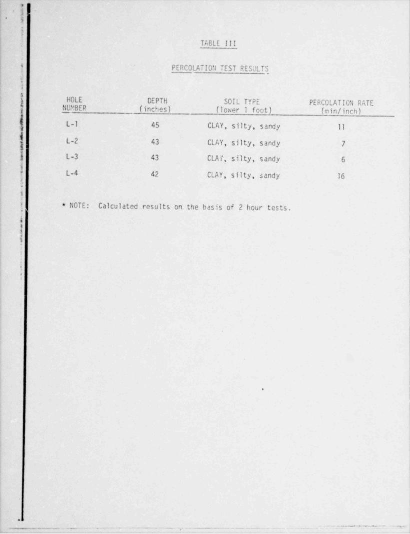
K7 tach field test holes L-1 throug5 L-4 were drilled for percolation testingk .'
'nd were not cased. The results of the percolation tests are shown on Table.
) III.
.j |!Subsoil conditions encountered beneath the areas of proposed construc-
k,j I
7} tion are discussed below.. 4
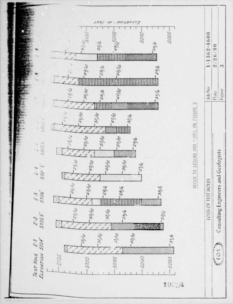
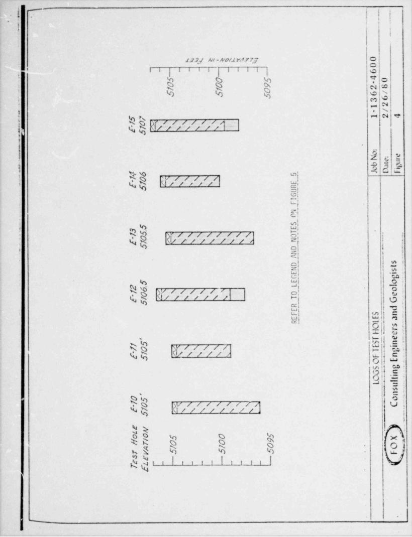
[ Evaooration Ponds (Holes E-1 through E-15)4
Subsoil conditions encountered at the location of the proposed evapora-i
'
tion ponds are somewhat uniform over the site but vary with depth. Generally,;,
| 0.5 to 1 foot of topsoil was encountered over 4.5 to 10 feet of silty sand'
to very sandy, low plast icity clays. Weathered sandstone was encountered in
6 of the test holes below depths of 5 to 7.5 feet (elevatims 5,102 to 5,097.5
feet). Specifically, the weathered sandstone was encountered in test holer,
E-3 through E-5, E-9, E-l.' and E-15. Claystone, sandstone and interbedded;e
; claystone and sandstone bedrock was encountered below depths of 5 to 11 fee:'
(elavations 5,101.5 tc a,093.5 feet) in test holes E-1 through E-3, and test
;. holes E-5 through E-9. tio free water was encountered in the test holes.:
! Field and laboratory testing indicates that the soils and bedrock mate-
h rials are slightly to medium moist with low permeabilities. The permeability
|'
3-L.
,
L |
|-. . . . . . _ _ - _.
-
. .
e of the natural clays, and ;1aystone and interbedded bedrock are on theJ
crder of 10-6 to 10-7 cm/sec. iiawever, the weathered sandstone has a much
f hicner permeability, and is on the order of 10-4 cm/sec.
4 Shear strength of the natural soi .s and bedrock is variable, however,jtesting indicates that the strength is high due to the partially saturated
;
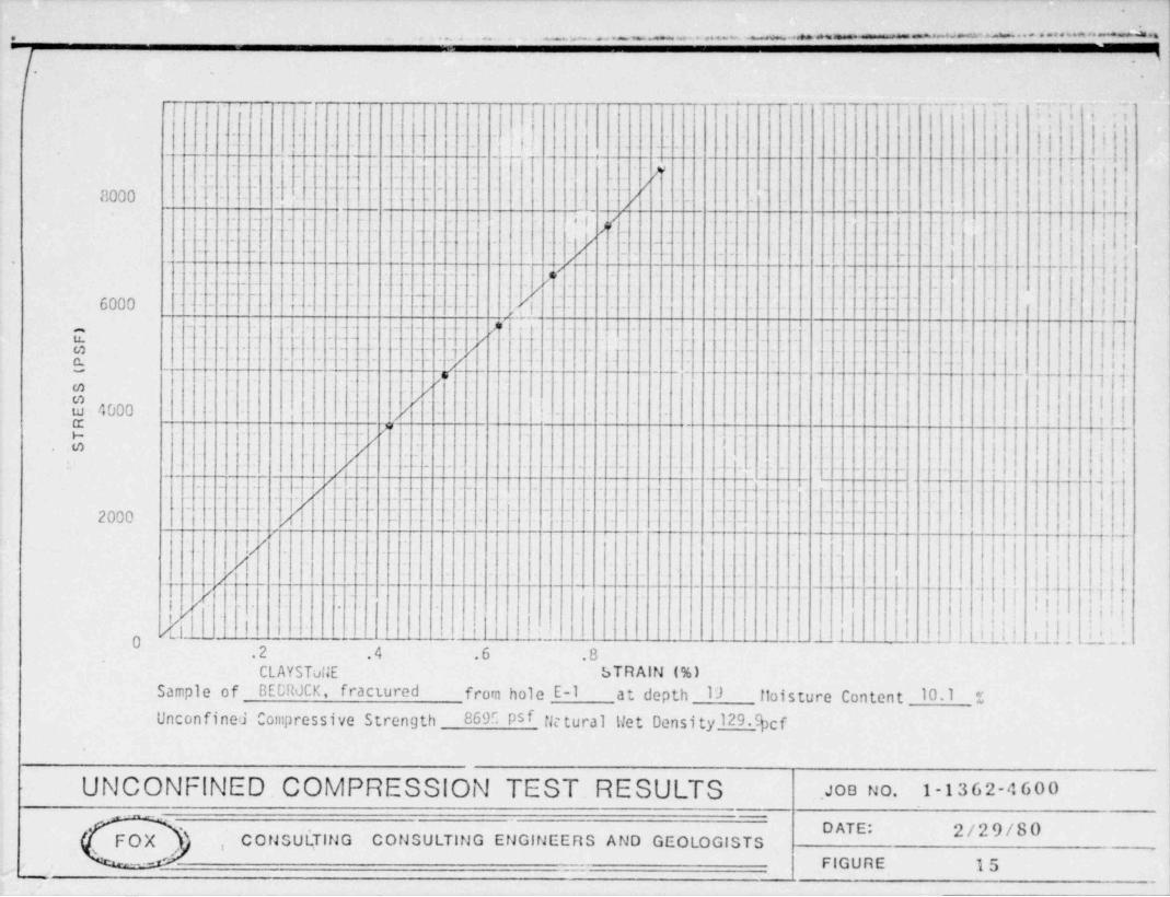
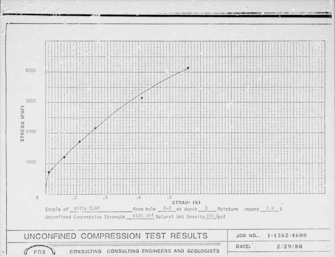
soil conditions. Unconfired ccrpression tests of the natural clays indicate
a strength on the order of 4,930 pounds per square foot, while the strength
of the bedrock materials range from 1,950 psf for the sandstone to 14,630n'
h psf for the claystone bedrock.
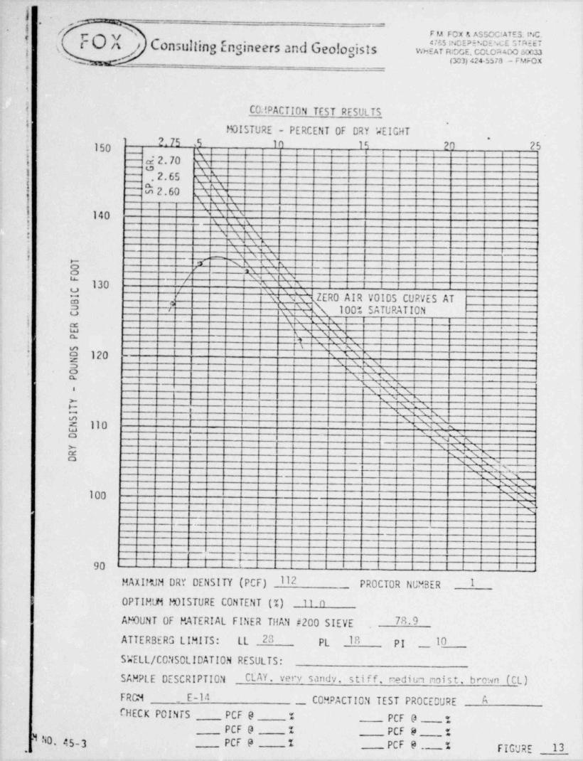
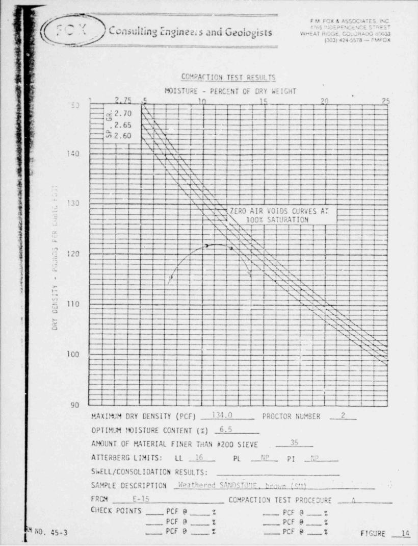
! Two Proctor compaction tests were conducted on the silty, sandy clays
and the weathered sandstone fnr their use in the construction of the embank-i
ment of the por.ds. These tests were conducted in accordance with procedures
outlined in ASTis 0-1557. The test results indicate a maximum Proctor density
of 122 pcf and 134 pcf, with optimum moisture CJntents of 11.0% and 6.5%,
for the clay and sandstone, respectively. In addition, unconfined compres-
sion tests of a sarrple of compacted clay remolded to 90% of Proctor density
inJicated a shear strength of 22,440 psf.
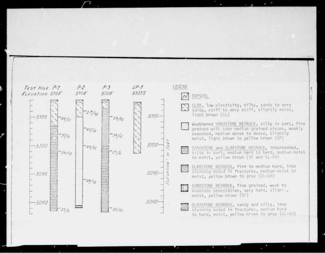
Process Area (floles P-1 through P-3)
Subsoil conditions at the proposed process area are snmewhat erratic
across the test holes. fioles P-1 and P-3 encountered 0.5 feet of topsoil
over 1 to 4 feet of silty sandy clays. Claystone bedrock, and interbedded
claystone and sandstone bedrock was encountered r elow depths of 1.5 to 4.5
feat (elevations 5,106.5 to 5,105.5 feet). Test hole P-2 encountered 0.5 feet
of topsoil over 2.5 feet of silty, sandy clay. Weathered sandstone was encoun-
tered below depth 3 feet (elevation 5,105 fee *). Interbedded claystone andi
sandstone bedrock was encountered below depths 18.5 feet (elevation 5,089.5
feet). No free water was encountered in the test holes at the time of drill-
ing.
-4-
f . )< '.
,
,
j The subsequent laboratory testina indicates that these ",ubsoil condi-3 tions process a wide variety of engineering characteristics with respect to3
} foundation construction. The clays and weathered sandstone are non-swelling;!
however, the clays are low density and will consolidate upon wettino under
light to moderate foundation louds, while the weathered sandstone will con-*
solidate under moderate to heavy foundation loads. The interbedded bedrock.
I has a low swelling potential, while the claystone bedrock exhibits a moder-I
ate to high swelling potential. The claystone has a swelling pressure of
approximately 3,200 psf on the basis of swell-consolidation data.
Leach Field (Holes LP-1 and L-1 through L-4)
Subsoil conditions encountered in the vicinity of the proposed leach
field area are very uniform. The profile hole, LP-1, encountered 0.5 feet
of top 3 oil over 8.5 feet of silty, sandy clay. Holes L-1 throuch L-4 were
drilled to depths of 42 to 45 inches for percolation testing. These holes
also encountered the silty. sandy clays. No bedrock or water was encountered
in these holes to the maximun depths explored.
The results of subsequent field percolation testing show that the clays
in the leach field area have percolation rates varying from 6 to 16 nilutes
per inch. Subsequent laboratory testing indicates that the clays have low
density in place and that these percolation rates are consistent with the
field conditions.
DESIGN ANALYSIS At!D CONSTRUCTION REC 0FFEflDATIONS
The design analysis and construction recommendations, based upon the
results of the investigation, are discussed for each construction area as
outlined below.
-5-
- - - _
~
.
t
)
;ation Ponds'
t
The main desion criteria and ceotechnical analysis conducted for the:.
ased evaporation ponds was the embankment stability, anticipated settle-
' ' of fill and pond embankrents, and licer requirements.
The stability analysis was conducted by simulating the proposed enbank-
Inf nnt gecmetry as previously outlined in a mathematical embankment model.
cdition, the strength criteria generated during this investigation was used^
fJcr determination of the factor of safety againe embankment failure. Two' '
i'
:ubility models were used to determine the safety against failure. Speci-e,
li[ fically, a wedge f ailure analysis through the embankment toe, and a circular'
j
[ 2rc failure scheme (after Terzcghi and Peck) were used. Our analyses assumed|4
tcn'd that the embankments would not become saturated due to the placement of the
-
;j Our analysis showed that the proposed 9 foot embank-'
internal synthetic liner.p
f ment sections in botn cut and fill with 3:1 side slopes have a minimum f actor
~i of safety of 4.5 against major slope f ailure.
Settlement of the proposed fill sections will be minimal because of_3
only 3.5 feet of maximum fill placement, and since this material will be
compacted. Additionally, settlement of the pond bottoms will be neglig-.
ible because of the removal of excavated soils and the filling of the ponds
with less dense fluid.1
| As currently planned, the ponds will be lined with a synthetic material. ;
Fowever, it is our understanding that it is desired to use low permeability
on-site materials as a back-up c.ystem beneath the synthetic material . The ,
ii
test hole information indicates that the pond bottons will encounter the clays,
weathered sandstone, and the bedrock ma'erials. These materials, with the
-6-.
I_ _ _
"-
. .
.
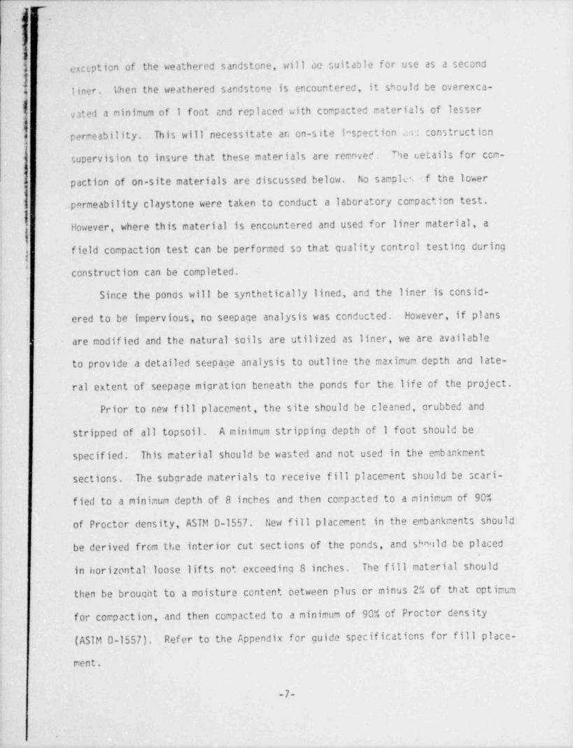
exception of the weathered sandstone, will ce suitable for use as a second,
liner. Vhen the weathered sandstone is encountered, it should be overexca-<
| vated a ninimum of I foot and replaced with compacted materials of lesseri
permeability. This will necessitate an on-site inspection m construction
]supervision to insure that these materials are remnved. The uetails for ccm-
paction of on-site materials are discussed below. fio sample :f the lower
permeability claystone were taken to conduct a laboratory ccmpaction test.,
1
However, where this material is encountered and used for liner material, a:1
j field compaction test can be performed so that quality control testing during
]construction can be completed.
Since the ponds will be synthetically lined, and the liner is consid-
ered to be impervious, no seepage analysis was conducted. However, if plans
are modified and the natural soils are utilized as liner, we are available
to provide a detailed seepage analysis to outline the maximum depth and late-
ral extent of seepage migration beneath the ponds for the life of the project.
Prior to new fill placement, the site should be cleaned, grubbed and
stripped of all topsoil. A minimum stripping depth of I foot should be
specified. This material should be wasted and not used in the embankment
sections. The subgrade materials to receive fill placement should be scari-
fied to a minimum depth of 8 inches and then compacted to a minimum of 90%
of Proctor density, ASTM D-1557. tiew fill placement in the embankments should
be derived from the interior cut sections of the ponds, and sbmld be placed
in horizontal loose lifts not exceeding 8 inches. The fill material should
then be brought to a moisture content between plus or minus 2% of that optimum
for compaction, and then compacted to a minimum of 90% of Proctor density
(ASTM D-1557). Refer to the Appendix for guide specifications for fill place-
ment'.
-7-
r-o
! .,
9
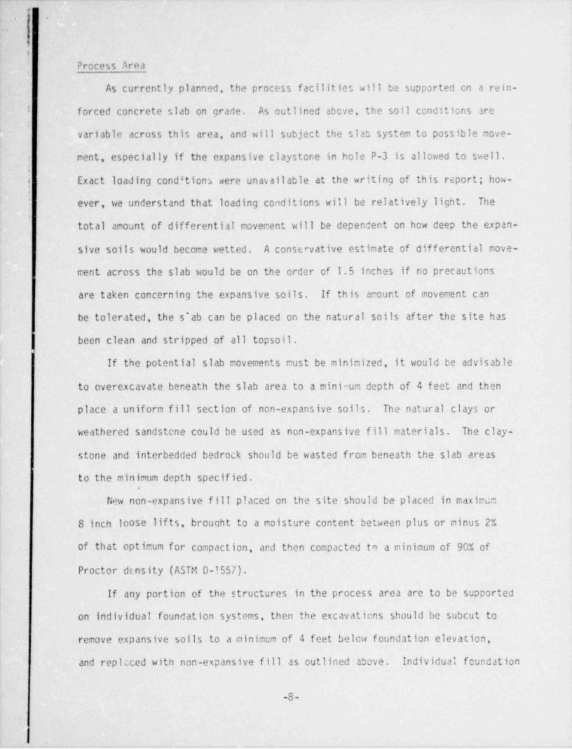
Process Areat
As currently planned, the process facilities will be supported on a rein-
I forced concrete slab on grade. As outlined above, the soil conditions are
9
variable across this area, and will subject the slab system to possible move-
ment, especially if the expansive claystone in hole P-3 is allowed to swell.-
Exact loading conditions were unavailable at the writing of this report; how-
ever, we understand that loading conditions will be relatively light. The,
total amount of differential movement will be dependent on how deep the expan-
sive soils would become wetted. A conservative estimate of differential move-
ment across the slab would be on the order of 1.5 inches if no precautions
are taken concerning the expansive soils. If this amount of movement can
be tolerated, the s'ab can be placed on the natural soils after the site has
been clean and stripped of all topsoil .
If the potential slab movements must be minimized, it would be advisable
to overexcavate beneath the slab area to a minimum depth of 4 feet and then
place a uniform fill section of non-expansive soils. The natural clays or
weathered sandstene could be used as non-expansive fill materials. The clay-
stone and interbedded bedrock should be wasted from beneath the slab areas
to the minimum depth specified.
New non-expansive fill placed on the site should be placed in maximum
8 inch loose lif ts, brought to a noisture content between plus or minus 2%
of that optimum for compaction, ard then compacted t9 a minimum of 90% of
Proctor density (ASTt10-1557).
If any portion of the structures in the process area are to be supported|
on individual foundation systems, then the excavations should be subcut to I
remove expansive soils to a minimum of 4 feet below foundation elevation,i
and replcced with non-expansive fill as outlined above. Individual foundation |
-8-
\-
-
.
1
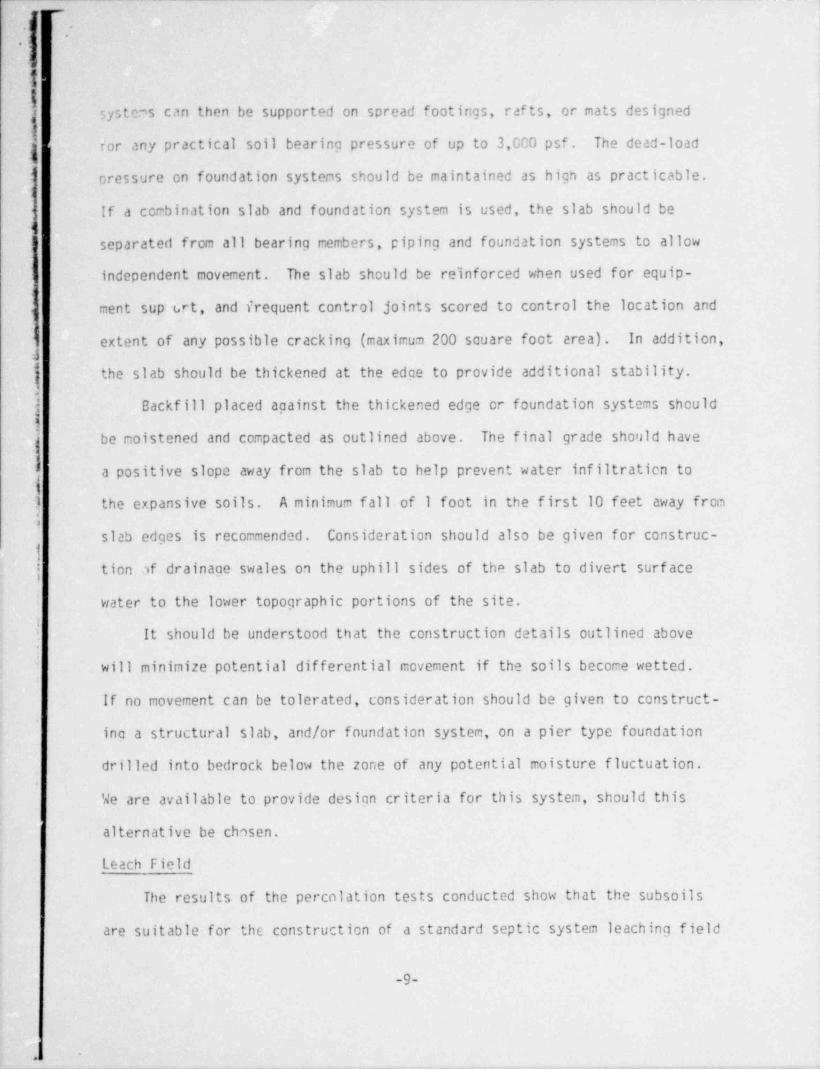
1; 3yste,ms can then be supported on spread footings, rafts, or mats designedL
.
for any practical soil bearing pressure of up to 3,0C0 psf. The dead-load
' oressure on foundation systems should be maintained as high as practicable.1
If a ccmbination slab and foundation system is used, the slab should beg
Aseparated from all bearing members, piping and foundation systems to allow
independent movement. The slab should be reinforced when used for equip-
ment sup:trt, and frequent control joints scored to control the location and<
extent of any possible cracking (maximum 200 souare foot area). In addition,'
J
j the slab should be thickened at the edge to provide additional stability.
j Backfill placed against the thickened edge er foundation systems should1
|be moistened and compacted as outlined above. The final grade should have
a positive slope away from the slab to help prevent water infiltration to13 the expansive soils. A minimum fall of I foot in the first 10 feet away from
islab edges is recommended. Consideration should also be given for construc-
| tion af drainage swales on the uphill sides of the slab to divert surf ace
water to the lower topographic portions of the site.i It should be understood that the construction details outlined above
will minimize potential differential movement if the soils become wetted.
If no movement can be tolerated, consideration should be given to construct-
ing a structural slab, and/or foundation system, on a pier type foundation
drilled into bedrock below the zone of any potential moisture fluctuation.
We are available to provide design criteria for this system, should this
alternative be chosen.
Leach Field
The results of the percolation tests conducted show that the subsoils )
are suitable for the construction of a standard septic system leaching field
-9-
J
-
'
.
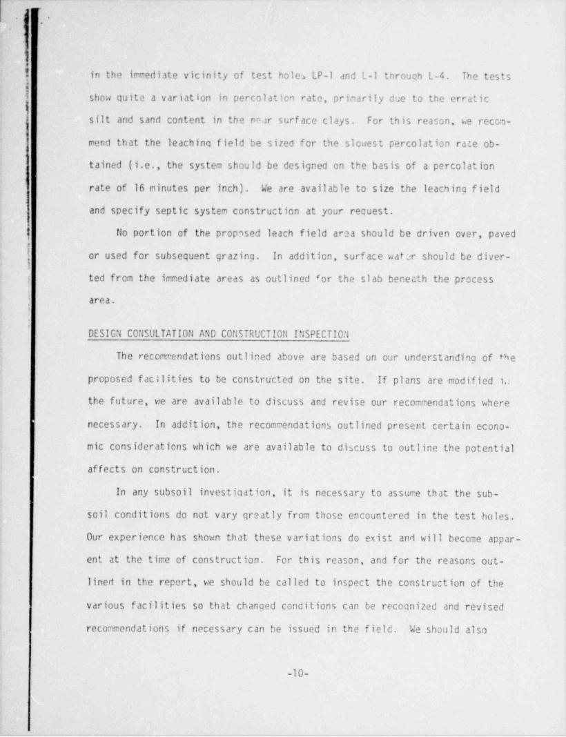
in the ir-mediate vicinity of test holes LP-1 and L-1 through L-4. The testsi! show quite a variation in percolation rate, primarily due to the erratic ih
silt and sand content in the rwr surf ace clays. For this reason, we recca-
mend that the leaching field be sized for the slowest percolation rate ob-
tained (i.e., the system should be designed on the basis of a percolation
rate of 16 minutes per inch). We are available to size the leaching field
and specify septic system construction at your request.
{ fio portion of the proposed leach field area should be driven over, pavedf
j or used for subsequent grazing. In addition, surf ace water should be diver-!
j ted from the immediate areas as outlined for the slab beneath the process'; area.t
DESIGil C0:15ULTATI0t1 AtlD C0flSTRUCTI0ft If!SPECTIO|1
The recorxrendations outlined above are based un our understanding of the
proposed f acilities to be constructed on the site. If plans are modified 1,i
the future, we are available to discuss and revise our recommendations where
necessary. In addition, the recomrcendations outlined present certain econo-
mic considerations which we are available to discuss to outline the potential
affects on construction.
In any subsoil investigation, it is necessary to assurce that the sub-
soil conditions do not vary greatly from those encountered in the test holes.
Our experience has shown that these variations do exist and will beccme appar-
ent at the time of construction. For this reason, and for the reasons out-
lined in the report, we should be called to inspect the construction of the
various f acilities so that changed conditions can be recognized and revised
recommendations if necessary can be issued in the field. We should also
-10-
- - _ _ _ _ - . __ . _ _ _ _ _ _ _ _ .
j -.
*
;.
:
be called to inspect and supervise the control of fill placement during con-
struction.|
Please call when further consultation or inspections are required. |
F.fl.?'- FOX F, ASC''CIATES, IfiC. Pev..wed by:,
4 / / j&R s' 'k w' ' s l-___v., .
Daniel F. Schneider Conald R. Clark, P.E.! Staff Engineer Division Manager,, ........,,,
| DFS/pcs%,,,, .. . .,
' .* .
fa / DONALD R. 0.., Q~ .* -:.. .
-
E 'd * CLARK : 21.
:W: :2 3 8 5 |; 9 |- en :
..
= + * . / *S
O ~(f 1, '
,
'Ellig g g g g g g g 655%
I
-11-
10034:
._ __. ._ -
y
m
1
cpygyzhf: ?,
),
.x m- n'Om e<s _
8t & a %m p A~ K C ....
sU h IIS jlS { .(
M<Deg6 b P'n 3 65 _ T :_,, ,,
3-
d,si-
r __y.. 4,g-. r .,m. m..
$s?hk~h,N(*\ 8 p
* 'y A , 'a\'E f
/ [f' '9,'I(M)
;% /-
fMS 28'
$QInV!Y[hkW
uu m a. a$D4 -
kQ) TDi&%%u a NDk}QNN, %@E ' D M E k 8h y h [ % p W, on , :-
.
f..f,. f, w.,J\ '[%&#I D -| m<I
\'
-
.fx. n:m2"[8.....1*:-..-,. .d . . . . . .W_Nt y. 4'
1:<.. .r, e.,
S;R N .
' }a?m;$.....Cf.,,* ...........i,
h ,'x ;[,+ a ( -
,*: - ......G,; ;-
-s ueu~ o rou ~%:| -| '' |:f | [ . ~ ~ ~ " ~h ,
I v ^ , s...... s, - +,,j.
s:
.
pr. %x -
n . <c . ./ rihNO'1 ') Q/ /
* ' ' ' "
,, ; ,,,,,,,..-n%e,... j .,j.l.....>
6
Pus-a ,a -
N. g A-
.
in i . m<v-.x <
*% %
.
_
_-
.
I
# * # W* 4 .
) ,
@(kl 'Nk ['
**'s.a> Ng ..-q. ,
. ,
.o Q-2 00*
h &]'. ' . . . . . .'
..... j\ S,. t
-
p% .... . . ... . .. . .,. .x.o.
s...s -. a .
-.
.
~ . .\ ;.a .
.... ..
}se, -)
.
!'%..
'
* ., .s
'.|,\ ..1 'h/.
) ,5-'-
,..
s f> &~h w:,% <a;i .-s 3.
./ c ....~~..>...: %'.2 mA y y .
? &w,/-
b\....t.d ,'h yk. . k Nasias 's 4 . . . ..
b is [ \, . . . ' 3 \ r
h D |)''.;\.
, % ' W" h ~~ ...,,,N|b
\ / ',
#s4Mo ]:h '. \.i% .+,d /~-, WW ,4'
euA ,.'Tt '1 .
\' ' -
/ ,,
Nr e is :'
t3 I o .,
), -g,
' : : ) .?__%,
m-.e_ _.:--||_j- . . _
. "
%)i | i JL J |*
?| f 2.'? ('' : n' -
,I fc. $,$ \ Q''" } [('
m
- +',,, s n.e- rOn\e
: -?
,'
.../- Qy .?,3 -9
'
; ,::,. .,,~ m .-
b (?'k .I Y12$L, M ' ' ' " ' ' ' ' *'
,
j\jh k,# VICINITY M AP~!
L- j _- |,--- _
IFOX Consulting Engineers and Geologists &
j,1...- g77sL2 kb No: 1-1362-4600 DAe 2 / 2 9 / 8 0Figure 1
10D 4
-
' - - - - - - - - - . _ _ _ _ _ _ . _ _ _ _.
_.
.
*- , gi
3 <
e-
LEGEND \E1O Trsr Hair locariou foo h oposto Eva pox A rica Po~os
.
t1O Test Noir loca tion Fon bro.=osto Les ca forts ,
.
'P-1 ?
|c 1*c.sr Hoir loca riox foo Peorocco Psccess .axtA ;'- ,s/
! | | 5 \ /*! f I ,- /-./ ' 44
/; ,
,
,I;5''R | /
| / ' .',i , ,
, _
/ .*
i [( (''| |'
'
\.
* * | n< s/ i i i\i ,. / + / i i
.. g g.
' ' \ N/ ,/ -\s,
i, -
j# /
.' / ) '\
.
,
/ / / | \
/ |'/ ,
5|. e I/
/'../ */*i / a'
,/a /. /
/,
,, --/ ,/ ..#
/ ././ c1,-"' '' "' *
. . -_ y -- ,,, ,, ,.
f ' '
. , . , '-- /
J'-[-'.. _,s.
f. ,, ..
..
--- , , , - ~ _ . _ _, /_.. ,,a'
. --''' ~ ~ ~ ' ~ --
/ ./ - ~~ ,- m.7 p.
,/ %s/ A CLL F.G.;> 4A'?4 '%
/-
/ * ** ~~p s gs
x %s' x x - _sx 's
~N N, 's.>~- <N ~,. ' . m,,x s s s.. _ s.\,s''s .
_s ' s ,, -'
s''N N. 'x .'. s,. '' N _ ;.~ A x ~' w'
s x. .s
x ., g ~,. < - y s .. 'x, s.' ~ .s~ .
~.~. ~..
,.
-._
x x.' x ~ . \xx .s s-N,. *N N s.sx s ss s
%. ,,s.'> xN 's. 's s N 'sx~ s s s-
q|-
_
.
&
.
\ N 's - -'' , .
's.N , N ,,,'s, s s. 'N s ,,.
','
'4 'N 's \'
x. ,
/ -. 'N , ' N . N N
's, '' '-s s,
N,- N,, x xs. s -,
/ 1 N - .N N
,/ s,
o' I \ \~
.
\.,/ / .
fi
,c-I \
s i t
e''% i i !-
1
'\ \ /
\ \ g
N x s ,
i \\A
.. \ s .
|Ni s
\ \ 's \ {-
N \ 'N - 1s .g Ni .,
' s N
| \ '' i' g
20.~)rr-- E 2 ,). 's \ I,'
' ''2M' e,# \ \ \'
f3--- 1, r 1 ,
~o e 10 0A \ s
-N 1 |/ N I /- 1 i_
;,
g i
-.1..\ f-10 r h. E-13 Y wt i ',' \'
\ '\O O e\.
< .g
\ \ \,,! j s, .
E-4 f 11 E-S E 14 / E4 \ \'
\;O- *O -O- tO "O | !'
- a a n. % ,- . ,s / i' ' *
~-
.- . ,
i*/ j/
| ! '''
g.72 f.ts ,.
| |/ '
*
O O . - * * * * / , ' i
g.y ? } N g.3A h.) ,'~ ~ ' ' * N '
7-
7
Q ,:O -- O;' i.,#' " '
r--- ,
i .- se \ ob T- '
~._l1 l-2 %,s
o o / -
2P 1 ) * r
>s. ~ ~~---- |l -3N,
\ '
.
' '" ' - 't *o \l4 .
g 'IO _O-. i r3 .
fmo ./ ;: 1,
||P2 %'_D )n
c |-|*P1*!
,*
,
. . / s'
-- -
) %, scm : 1' tco*,
i %
.I._ (NN %;% ~'
J, _ ., ,.
'-' j lEST HOLE LOCAllON F'LAN- - . _ _,,
_ _ _ -~ . _ . _ , _ _
FOX Consultine Engineers and Geologists' '''
. ,~~. --s. , . _ _
___-- . _ _ _
N . , '' ~ s .. kbNa 1-1362-4600 |Date: 2 / 2 9 / 8 0|F8ure 2i -} ()i' 34
'
.
m "
e' --
.
. . _M
|j|j<
' |
-
hQ gs - Rkq,
- -___: _ _.
y 5 0 5 09 9 8 0:^ p,u 5,- 5 5
0 0 0 6'~ ,
U g7 9 4 0- -
~32 8* 3 4
~ ~ 6 /.
%a. _ 63i
2', 1- /;
- a t, g 1 2 3y / y~- _
8 63 ~-4 si- ~, _- ~
_
. \ - - ,
.
_-
:
o2/g g$ z N : e/6
f- u/,re u6, 0 b t
. Jica,
I 2 4 o D fo
> - ~ ~, sg; - : 5
_?. : b_
,' :
:..,
.I \ . E| :
RU' j J Gg d# '/*I
_
2 F-,
G% _# ', Nu : O% N ?\5 gQ\gQ ' . +2j
I : 5-:
E -.
T .2 p )0 )0 V O "" .
2 ;0 6 .-
/'
3 ,.
-_ $ 3S s 5 S g D _
j Nu - ~ ~ _{ - _o A sf '
,
- . t
:{ . . ' NS \d \ ;
, D s! '
i
o_gEy E 2 2 Gf / f
/ // / V6 E l
'S ff 0 6 L o_O' 1 e.i Y 4
~ ~ ~ ~J ~' O GG/ Ng
' T
5 \ ;\ n_dR\ \
a _..E SF E
L
y'~' ,,,, ! ,,,ER O s,.
r- H e ._' g.6 y , g , T e.
0 _, S n_ _ E ig.1
_ - - m. . .
.
% \ . T. 5 .
F n_g | :
t
EOy 2 2 S g.f/ // / % /, G n7 0 E 0, O5 i
t
2 4 S E5 ~ ~ ' ~5 l
L u,l '
0 / s
. sYM !w1 r. | \[\\ \ a* <..\\ \ 3y g n-. 5 [ s -. o__ ;
C____
_ 4 g, % 9 .
2 ' .
.
.
l '' y f_ 4 3 ,O'/ ~ - - - .
, ..5 g
|\\ \\s \3: . .* ,
g s s ' #X..
:~
"= 0,V. 5O 0 o 5 0 5 <f~/T / c 9 9 8
#(+. -5 0 0 0b 3, 5 5 5t
_E _ ~ _ __ . __ _LE _
__
. _
. C y:h_
_.
4c-_
_
_
___..
_
_ ; ,I, ' ,. j ' ' , !!
_ _ _ - _ - - _ - - _ _ _ _ _ _ _ _ _ _ _ _ _
!.-. -
Ii-
iii
i iI
.
J 7.7) N/ = N0/1 Mf 77] Oo
5| | | | I i|
1 I I LI I g
g g % 7 0N T,
i N w. 5 C N
ceN-
l . NM N *?* %t
q q%s|)f/ / -/ f / / / ---N / / // / -f /<
1.
6Z U N
, o a e1 3 a cv,
, ,|. h% G'V,
/////N /' / r s ./ y,1 %
=t0;
Dt
C|sZ
DM '
% S( / / / / /. / / -/ o' ;
% \i/ / / / f f=/ / ) = ; .
'6O
, b L,
!E i
E 3'Ci .3 ,G cn .
'
q %.'
/////f o
La _o ,s|
r
O%N
Q /'/ / / // / F-
e, =.u-i en ='M U U
O me: D%
'% bi l. 3"kp g/ /'/'/ / ? c}
w =.// ///Q __
O w4
zn ob <O CO C'
3.-'
$$s
6iQ% --/ U;)V / / / / /,/ /.
% \\/ / / / / / / / ,
9
h
bD i
S$*@
8 D xs
ss 4 8 : 2I*e' q i , I , , i i I i i i i I
-
-
.- . -
I- - . . ...
I \
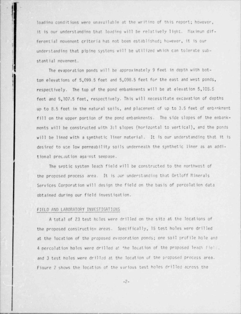
Test Hoit F1 F2 F3 LP-f LEGEND$fzrv4Trav 5/03' 5103' 5/03' 51075
! m e m - [ TOPS 0IL- <e
ny 3- K CLAY, low plasticity, silty, sandy to very
- N (.'
3 sandy, stiff to very stiff, slightly moist,Np 77'' E:!:'' 's -- A
s5/05 - 1ight brown (CL)
- 5/05 \* C [E :: ,6/2 N Ng6 /2
k.::.:/: -N
\ '-
\ Weathered SANDSTONE BEDROCK, silty in part, fine-~
~40ff ks ,/ s - grained wih some nadium grained pieces, weaklyN-
~
-;N
- cemented, inedium dense to dense, slightly~34 f2 N-
_ j 30/6'
/ moist, light brown to yellow brown (SP)- -s s - g\
- 3/00 4#d? \s 5/00 - D' =,: 's - SANDSTONE and CLAYSTONE BEDROCK, interbedded,
- ~36/fy ~~f% d - silty in part, medium hard t D iard, medium moist-
~ ,g to moist, yellow brown (SP and CL-CH)_
<-
$CLAYSTONE BEDROCK, firm to medium hard, iron"
-_
E staining noteffri fractures, medium moist togggg_ 3___ggpg -
_ [ moist, yellow brown to gray (CL-CH)_
~4V12 - Q*-
- SANDSTONE BEDROCK, fine grained, weak to.smoderate cementation, very hard, slighr '.i- -?xr
- ''
-- moist, yellow brown (SP)
5090 -1 - 5090 -
CLAYSTONE BEDROCK, sandy and silty, iron''
-
24/3 [72/fj- \'.^
staining noted in fractures, nedium hardto hard, inoist, yellow brown to gray (CL-Cil)-
-
|.
i
|- . o ..
. - - _ _ _ _ . - - _ . _ _ _ - -
' ~-
p NOTES'
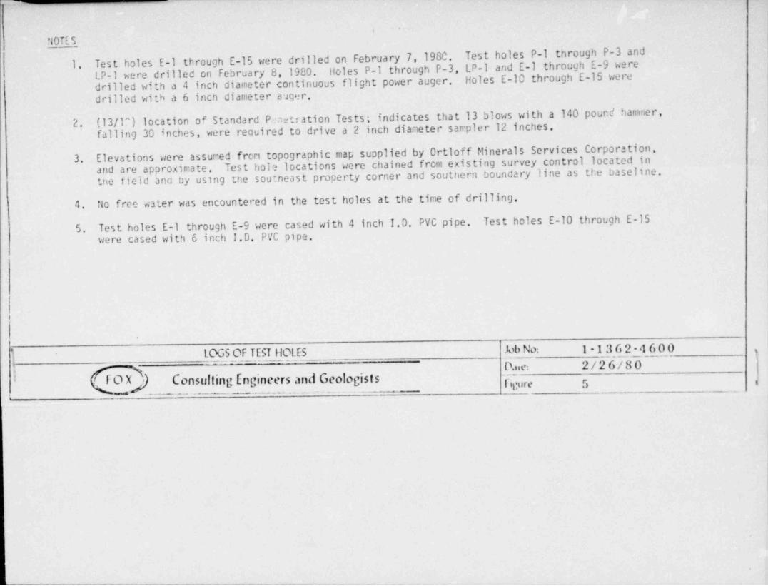
Test holes P-1 through P-3 and1. Test holes E-1 through E-15 were drilled on February 7,1980. Holes P-1 through P-3, LP-1 and E-1 through E-9 wereLP-1 were drilled on February 8, 1980. Holes E-10 through E-15 weredrilled with a 4 inch diameter continuous flight power auger.
drilled with a 6 inch diameter auger.
(13/1^) location of Standard P.m::tration Tests; indicates that 13 blows with a 140 pound hanner,2.falling 30 inches, were required to drive a 2 inch diameter sampler 12 inches.
Elevations were assumed from topographic map supplied by Ortloff Minerals Services Corporation,3. Test hole locations were chained from existing survey control located inand are approximate.the field and by using the soutneast property corner and southern boundary line as the baseline.
4. No free water was encountered in the test holes at the time of. drilling.
5. Test holes E-1 through E-9 were cased with 4-inch I.D. PVC pipe. Test holes E-10 through E-15were cased with 6 inch I.D. PVC pipe.
i
.
LOGS OF TEST HOLES Job No: 1-1362-4600'
I_
D.iie: 2/26/80j
FOX) Consulting Engineers and Geologists ricure 5 i
|
ii
.
_ _ _ _ _ _ _ _ _ _ _ _ _ _ _ . . _ . . _
,
_-
.
__ .
_ E{* Y u - :% ;*, 2o.
0 O 0 0 o 0 0 0 co 0.1 2 ? 4 5 c 7 8 3 i0
||.
00
c.
.-
. ,
.. 5 t0 e--
0 Y er
t<0 A f _e _L _
e-
- _C 2 _
m - r- o - 4 o h0 tr
d 0 T py L eH--
I
dS_ t
_ a
5
_-
5 E2
y 5 eT 0 l
R o0 llA qH || t0 - -
N sC 7 e- 1 s-
0 '4 0r T
_1 N e
t ,eS s0 tr 0 mI
e1 ie eS l
i eb ln
Y m0,
\i F f
L u7 MN 2
A O ni
eJ\ hN v o tte0 r i pAS 4; S. i
O S ed
d O Dr n N td) ia A m aL a
A n 0, r S u .
C a? i G i 4tdt - eI S6- e E eN 1, M f
A S. 4, eI
l 5H U| loC o( hl
E o ts t p
M sersp o ede o
Th C tcinf 5
II mao
n r5i} f -s - Een - 0 in Ygf
Aei 3, 1 Fn Llef L C op HO
I E fVe [4 AI otv s 642
iPi
Re ee 21 1G l TS p = = =ed mds
r an LLIra '2f o S a LPPd O onc S Ci
S. i|
S. f _ -
- .OU _ - - .O
6 0 0 0 0 0 C c 0 C 01 0L7 6 3 4 3 2
1 0 9 81 1
{3 ' E. :8 ,E 21;
--
1
mroF nny n- c
l.
*.. . . ....o-. - - - . . - -
Form 2-116
M EC H Aff lC AL AN A LYSIS CHARTU.S. Stendard Sieve Cpenings in inches U.S. Standard S!sve Numbers Hydrometer
100--)--? Ih { ?[4 9 p p p p :q 1416 . 70 30-_4.0J0._2,0402pA?,M 325 o-
r- . N I I
00 -- --
N-
Ns80 - N 20
~r
{ 70 --
50{a;. s's
s 6C 40 A.ou
.? SC --
50 *: :// 2
40 60-
2 - -co
2 -2 30 70 2
20 00
10 -
j0
010 0ICO 50 10 5 1 05 0.1 0.05 COI 0005
.
0. 010Grain Sire in Millimeters
G R AVEl _ SA.!JDCoorse 1 Fine Coorse ! Medium I Fin e SILT or CLAY
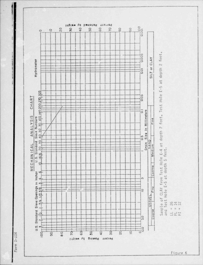
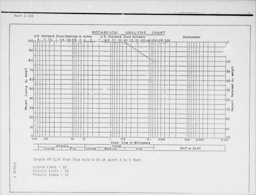
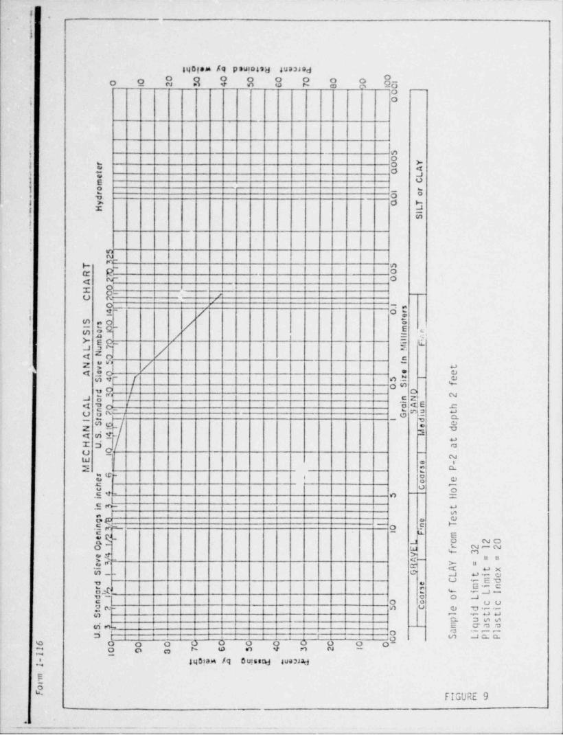
Sample of CLAY from Test Hole E-14 at depth 3 to 5 feetn5 Liquid Limit = 28E Plastic Limit = 18'' Plastic Index = 10y
- . - -
-
t,-
~ .
~,
-_...
.
E{* wm s:. E:= 7 Eg.
t '
0.
0 0 0 0 0 O 0 0 0 010 1 2 5 4 5 C 7 8 9 10'|
_0.. 0e..
.
_..
50
r 4 0 Y-
e - 0 ALt
e Cmr- o 1 or 0d
y Q TLH I
-
S
_.
-5 t2 e
T g 5 eR M _0 f
_ 0yIi 7
. A 5H
NC fQ, \ 1 s h4 x 0r t
_ 1
\e pt
S s0 e em dre0 N
l
F
I
ie. S
Ai
inb l
tY m0 y M a.
L a7\i
f n 5A 0i 1e5N -v _ ' e
S4 5. ii
EA teO \ zs O S e
d 0 \ D l
or 3 n NL Ni
A mc H'A d ac }0 \n r S
I ,i G iu tC
i d sS 6 e e
N 1, \ T4, MA S. 1 m\H U o
C 0 rE
1
1
fosM r Esp a le _ o t
h c 0c _.Ii
ST
in f._ 5Dni} lt
As e Sg4n ini4 01 F d . .n e P. Peyp L r .
t l
OI
E e 6f f
e4 V h 1
v A| t = =ey R a =e t xi
S1, G W ti emdi
d e minr sah f iLIr
a o Ld t
0 o ccna2 5 c e diit
S .^ l ittp ussm qaa.
iI
a il lS. p.
_0- - 0
U - - - - - S LPP6 0 O C 0 0 0 0 0 01 0 7 6 5 4 3 2 1
O|1 1
9 O- .* y .s:a ,022
2
mr
YCe"(ibe
o '
55r m5"F t
,
~ .
,
-.
2" . Y m.$ $ ,yy,
'
o0 o 0 0 o 0 o 0 c1o 01 2 s 4 5 c 7 g 9 i0
1|0. 0-
.
. 50
~ 0 Yre 0 A
. t L
-em Co
1 or
r. d 0
y Q T- H IL. S
. 52
T ] SR M 0
A q 0
H 0 .
p * - I|
C ? s -
0 1 s.
I x 0rqe.
S s0. t
N e
bf Ni "f
mrI
oi [eS
0 ll .Y m ], Ms
;
L \uN _A Q ne5 i
te 0_ NN v te eA
S4 5 5. ii er
Q O S f
dU-s i
Am h
Dd2r n IL a P
A an rC a% SuI
Si G i
tp
t d eeN dA S..
Mt
H U aC 0E
11
2e -
M s Prsp
- o ee oh lCc onf 5
II
Hi - -
inf ts- -s e
n !
og -
i 0 in T
p@1 Fn me
L o 20r 21 2O' E f 3e4 V = =eTv AI Y =R A t xiS! G L ti eC mdi
d e minr sah f iLIro o Ld !- O o ccn
e7 S C e dii-t
S -l i tt
.- p uss- - m qaa
S. f - I|
a il l
-- 0--
U - - - S LPP_ - 0-6 O 0 0 c C 0 0 C C
01 067 6 5 4 3 22 O 9 31 I
55 %a .j.S E$- .
I -
mroF Ae
',| '! .' :!'
N1 __
_
~_
r ,mn :* ; 'g ___0
0 0 O 0 0 0 0 01o 01 2 4 S c 7 8 9 10
* ._0- 0
- -
_
-*
-
=
S" O YO
- r AO- e Lt C' em ro n or ' Od C Ty LH IS-
-=-
5. 2. 3, S.
. T 0,.
3. R. 0.. A 2..
H oIiO..
.
C p
_ 1 Y
1 sQ 0r4 e
t. e. S s0 m e.
e0 l nr i tI
Y m0_- i F
S b l i eM e-_ f
. L a7 \i n. A 0f 5i
e5N Nv e o. r. A te0 5. ii t
S4,'.O S D 3.
d0L a
in Nr3 hAma tA d 0 l I G i
er S u pn
C a2 .3k I d
I e dt
. S6 M.
_. N 1 tA S. 41 aH U i 1
C 0 -1h PE s LrM + a
sG - o ee
, c lh
_- II
Hoc $
in f=_ tnyi s
. e esg1' 0 in Tn /i3 1 F mn -
L o 31epO
I E r 41 2pf 3V = =e4 AiY =efv R A t xGiS{ L ti e
mdC ied s min
r f i LIr 2a [ i o o Ld 0 o ccn 5 C e diic$i l i tt
ql p uss. -, - 0 a il l
S- ,- || m qaa-S. f
U - -..
- 0 S LPP- --
6 O 0 0 0 0 0 0 0 0 O16 5 4 3 2 1
1OI 9 8
1 5,I w^ Y:E c@2'd-2
mro n5Em bF.
!
.
: |'j I :!|| ;|| i i ; .'
-
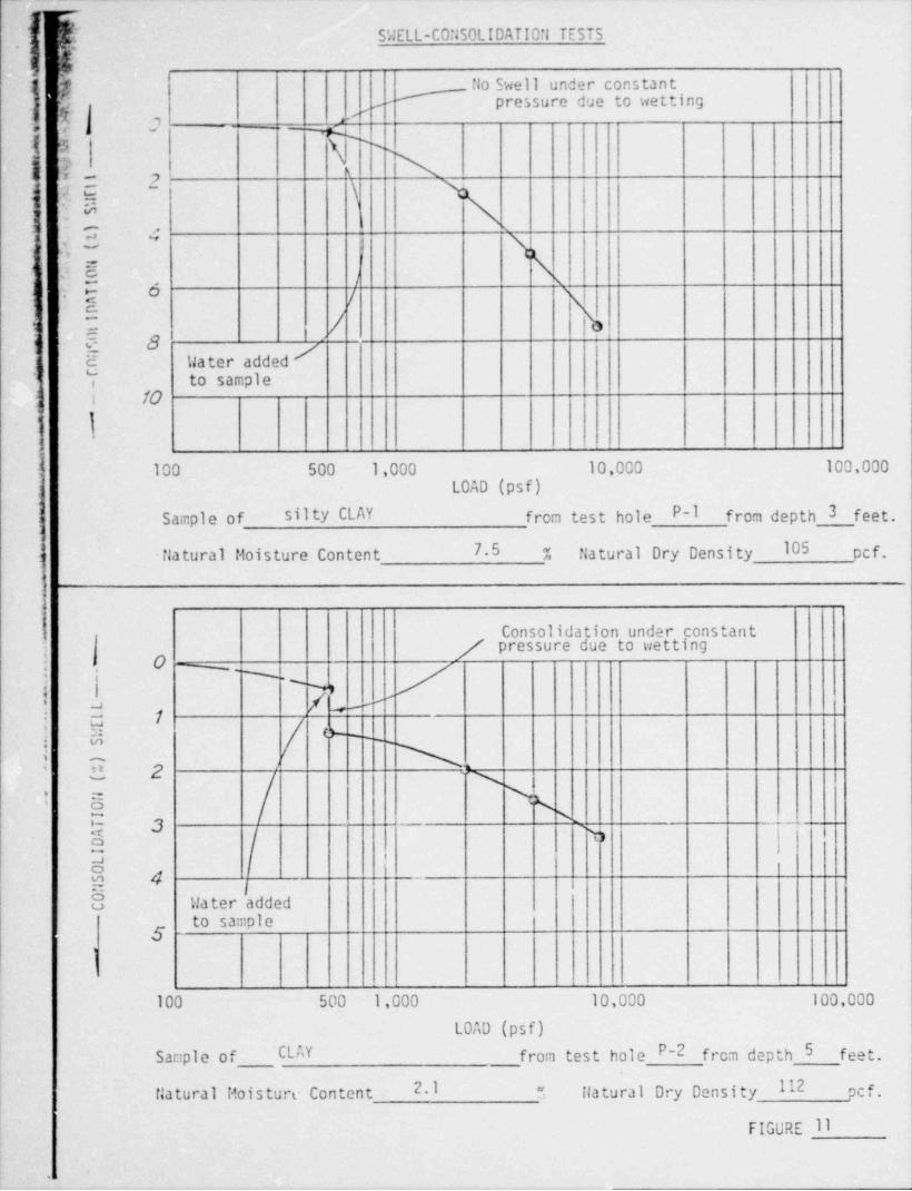
f, SWELL-CO:150LIDATIO!! TESTS,
5g flo Swell under constant,
pressure due to wetting-g -,
A , >'*c i
_ _ -g;-
IA N
| '.e,- s\s7 '
.. p'
.o\n , w
,1! ~\<
5, '. . )i y o
7
| |1
- C 8 y{ Uater added;
to sample,
1 ! TO|,
l- 100 500 1,000 10,000 100,000LOAD (psf)
Sample of silty CLAY from test hole P-1 from depth 3 feet.
flatural Dry Density 105 pct,i -itatural floisture Content 7.5 "
iConsolidation under constant
/ pressure due to wetting;
i O N-; % '
| 1 M/- ,
'-j1
-.
u! Si 0- - - - ,
3 2 > .c
I 5 \p 3 N _.
E h | i I
I3 i
| 4 ;8 Water added
to sample
1
100 500 1,000 10,000 100,000
LOAD (psf)
Sample of CLAY from test hole P-2 from depth 5 feet.
112 pcf.fiatural fioisture Content 2.1 llatural Dry Density",
FIGURE ll
~ ~
,-
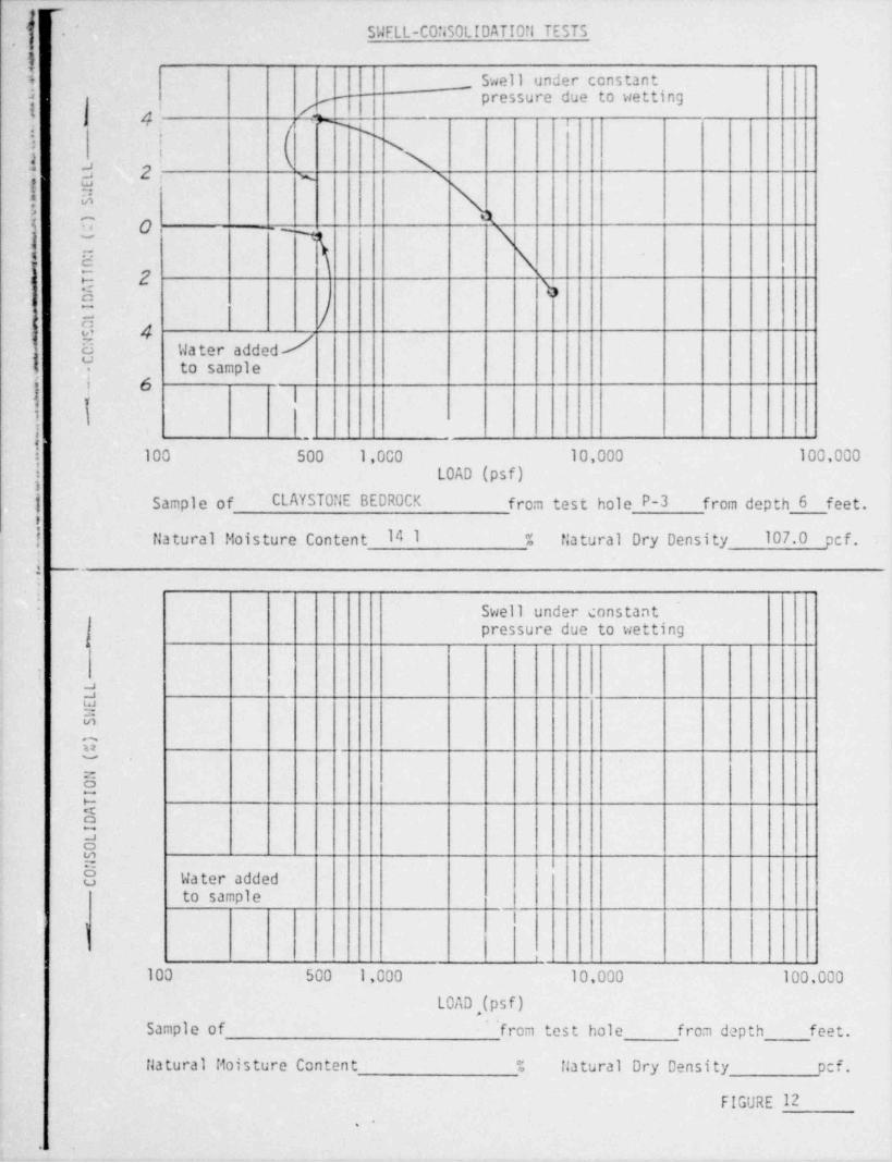
. 'f SWELL-CO iSOLIDATI0il TESTS'
1
I _ Swell under constant |J pressure due to wettinge ,
i /4 k n,; gi ; N3 \aj e 2: i,x s
f 5 \A; 0 =~-
3 \,
b E \i 5 2 %
0, /e 4o
6 Water addedI Y to sample
J( | 6|
k:
!! 100 500 1,000 10.000 100,000i LOAD (psf)1
| Sample of CLAYST0:lE BEDROCK from test hole P-3 from depth 6 feet.i
| flatural Moisture Content 14 1 % f;atural Dry Density 107.0 pcf.
i -
4
,
Swell under constant,' pressure due to wetting
j
dg
)
G-
:-
2eedN8 Water added
to sample_
i
i
100 500 1,000 10,000 100,000
LOAD,(psf)Sample of 'from test hole from depth feet.
flatural Moisture Content % flatural Dry Density pcf.
FIGURE 12.
&
{ g' T n vN,
F M Fox 7. ASSOCtATES. t*.C.'e
s L UA > Consult.ing Engineers and Geolog. ts4n.5 inespe.ce.cE siaEET~
'
is wrE^r accE. cotoaam amaa1 /,,_ % .. (3nj 424 557a - rusox,
.
i COMPACTION TEST RESULTS1
} MOISTURE - PERCENT OF DRY '4EIGHT.
2.75 ,5 in is 20 25'
: 150
_ g2.70 \\ | |
i\ i i , i i
{ -- '
I z 2.65 \/\\| a \s\
Z m 2.60 <u\ \\ \ \\
,, \l\ \\l 140 ' ' '' \"s
'
; s \; \l\ \1
g T \ \\. X \ 3.'
. _ \ \ % \,
_ s s i\ s! - .f x s tx-\ i, o < ,\ i\ \ , , *O" / | Nw Ni AN
_
i 6 i130 ' ' ^ L'^ ' ' ' '
S / ' 'M 'J x' < ZER0 AIR VOIDS CURVES AT i8 \' s '^ s'k 100% SATURATION :*,
o.
\ \ .ss.j g T A \\\
-
_W \ \ %) \ ''m 3CL'4 \ NNN
!' $ 120 - 'NW'sj |
\ AiXAN !
,
2O xxAx >
NtNAN
' 'IMx, \A N 'N N>-
H ! A s\ X \~ I 1 'N \ x i
i i i x i A N_ \ i$ 110 ' ' ' 'UxM ',
x 4 x. .K !O '
'
, x xxx ,T NX\x I
% \ A 'a i
Ngx xx x,x x.x
100 *.x sx
~_
_
J_. _i
90 ' '
MAXI!*,JM DR$.' DENSITY (PCF) 112 PROCTOR NUMBER 1
OPTIMUM MOISTURE CONTENT (%) 11 n
AHOUNT OF PATERIAL FINER THAN #200 SIEVE 78.9 |
ATTERBERS LIMITS: LL 23 PL 18 PI __ 10
S'WELL/CO.'iSCLIDATION P.ESULTS:
SAMPLE DESCRIPTION CLAY, very sandy, sti f f, mediun noist, brown (CL)
FRCM _ E-14 _ COMPACTION TEST PROCEDURE A
CHECK POINTS PCF @ PCF 0 :PCF G % PCF @ %
M NO. 45-3 PCF 0 % PCF @.- FIGURE 13C.
' ' ''
F M FCX a ASSOCtATES. INC.-'
r ,m $/ 445 :';CEPENCt%CE CTGEET; , " 's lCOSUIIIDS t D33D22i5 and 600|0g!5!S
. .-' ~
. . .
V rE m M . C p C ^ 33,.
/ (%3) 424-5573 - FYFOX~ --
_
'
!1
COMPACTION TFST RESULTSa -
[ 10ISTURE - PERCENT OF DRY WEIGHT,
f 1 2.75 ,5 in 1c ?n 75.,3 i x >; -
i i-
|cd2.70 x\_
' ''
{p. 2.65 [v\a. \ s\.
E io 2.60 .\ \xg \ '. \i\
I \ \ \ \ i' ' ' '.; ,
140 \ ''* \ s es 4
,
\ \ \ ii
; \ \\1 1
~
.AN* \7\ '*
\ ' . I\ \. f-- \ \\ \ !r ' xs\ \ l i
2 y \ \s . . 4-
339 \ m'
'5 Y'y D.ZERO AIR VOIDS CURVES A! I i.
l \f'x'h 100% SATURATION |'
,
- s x\N i i
cf. \ \ M. \ i.6' \ N\l
*- L4. N rs %!\_
p. %v x N x.
a e . u t s ex i i,20 ,- nex, n xi i3 ., , , i
1 / \ N T \ !N i i f i- G f \! A i \ A \_i t I
-/ s> 1 N\N i
-
, o xixx x-
/ ' NxN>- .A!AiNt- xxxx"
! N ix X xi i
U., 110 ' " '+ x :' ' '
t i v\ . .__a x y xes e i
x x\y .I >-N N_ x ex is x xxx i
. x x x. x ii xxNxi
. X x N N,*
pi xw,
100 ' ''' "x s, .
x
.i
90 '
P.AXIMUM DRY DENSITY (PCF) 134.0 PROCTOR NUMBER 2
OPTIMUM FOISTURE CONTENT (%) 6.5
AMOUNT OF PATERIAL FINER THAN #200 SIEVE 35
ATTERBERG LIMITS: LL 16 PL IP PI W
ShELL/ CONSOLIDATION RESULTS:!
'
SAMPLE DESCRIPTION Weathered SAMOST0*E %cm (c'n
! FRCM E-15 COMPACTION TEST PROCEDURE a
| CHECK POINTS PCF @ % PCF 0 %
PCF 0 % PCF 9 %-
4 NO. 45-3 PCF 0 % PCF 9 % FIGURE 14.
.=
.
- . . _. ._ -_._ _ . - _ e m._ m . . . c .c . .. . . .
. T
-.
1. I1 e i ||,.
-
i !!, !;ji
. ' ' '
|! ;i
- ,,| ||: i|'. . , j ,_
-
..!.__ ___ __ .. - _ . _ ,
~ ~ ~
: _ . !8000 -
. / -f 'lI I_ _ _ _ _
||| |ei, i,
_ _ . - 1i; j' i, || TT..
- ~ ~ - '
_j j~
fj ;||. . _ _ . . .. _ _
__ . j._--
3__ _.,._, ,
_ _ _ _ _ ..
| ,; 5,,_ _
. . . _ _ _ _ _ . p _ _ _ j|ge
6000~ ~ ' ~' ~ ~ ~~ ~
.[i'
~'~
I~ '
|||- - r- - - - -
| |
_ .j _ _ _ _ _ . _ .
m _ _ _ _ . _[ff'. . .
. | .. |.
g . . ,. . . _ _ _ _ _. _ _ q_.y _ _ _ _ _ . .| !~~
,. _
,. _ . _ .
|,,
C- ' ' ' ' '
}. __._._.._ _.i_ __. __ _ . , _ __, _' , ' .
~ '
m . / ;e - / . !| | |w 4000 f- |r! -
, |: , , ;,
ms - - -
p i- ,.
|
\.
m 7,.. | l
- np
fi *'- /
'
i }_. /. . _ _ . __ _ ._ _ _ _ . 4 q_____| _;i
,
. ___ . __ _ ,_ .. .j -.
g~ ~ ~ ~
-
. . . . '. . . 1. : . : . _ . . _ _ _ _ _ _ _ .- . _ _..
-
__-.-- __-.__ _, _ . _ . 7_../ -
il
/. '- '.,
- --_ / -..--- - -._..- ...__ -- -- _- _ __- .... _ . . _ _ n__._ _ _.. - - . _ . . . . . | i. |/ Ii
'
.
y'I..
l.
It !i - 'i fi;i-
kl} | ! i l ]_d| ii!I i||: !'t
.2 .4 .6 .8CLAYSTuNE . bTRAIN (%)
Sample of BECROCK, fractured from hole E-1 at depth 19 floisture Content 10.1 :Unconfined Compressive Strength 869r, psf fictural llet Density 129.%cf
UNCONFINED COMPRESSION TEST. RESULTS . JOB NO, 1-1362-4600'
DATE: 2/29/80. . .
CONSULTING ENGINEERS AND GEOLOGISTS'FOX C O N SU LTIN G,' #
. . _ . -- _
FIGURE 15-
,
_ _ _ _ _ _ _ _ _ _ _ _ _ _ _
r +~ .- .
A - ~ ~.- . -. W .* ) ... . ..... . - - .~ . ...-- - ..-_
_,
r'
.
*_
l
-_
,| I ij ' :iQ[j
_ . _ .
''
_ l- ' ''
it!j.| 1ii;
. ._._ _ -._._ ___.__ ___ _._ _ ___ _._ __ .. . . _ ,
' '-
: : _ ... : : . { : .. .
|~
_
_ _ _ _
j_ .
jf i - - -
_- (|l ,
_ : _ _ . _ . . _ _ : : . . : ::;/ _ . . _ . . _ . . . _ _ .|jl- -
,
|I[ - -
!|~| i i
i o- -
g. _ .
||* - ~~~ ' :-
,
t
3000 J- - -/y '
! !!
L . /. ; i' ~ ~~ ~
T' _ .
a | _ _.. . . . j __ _ _ '._ 7. ._ .
.. _ _ _ . . y| / _ - .- - . . 's 1: st-
u) * - [; .'J_
- - -
'-- '~
I " !I
- - _ - - - - - | |I!_ _ _
y2000 J_ i ._ . I -
g . . . _ _ _ _
_ _ _ _ _ _ _ _ ._ . _ . _ . _ . _ _ _ _ _ _ _ _ _ _ _ _ . _ _, _ _ {g ' - - - -
.g ~ ~: 1~_ :~~
~~. : .. 1: .~ 1- ~ ~ -
: . _ .1 1~_ . . _ :~ ~ ~ ~ ~
_.11. 1~ ~~
.|. _,_._ _ __ _ . __ ._g .. _
_a__ _
.v _ . . _ _ _ .
,4 _ --
1000 , _,/_ . _, , _t . . j
- - ' - -
. . ._
|.. _._ _ q _ _ .._
t.,. . _ _ _ . . _ _ _ _ _ . . .
I _L .' _}._.__ _._J _-
- - -
'
. .. . . . - ; i.. . _ . _.. _ _ . _ . _ . _ _ _ _ - | j
LI- t I | !, ,
0 .2 .4 .6 .8. STRAIN (%) .
Sample of silty CLAY from hole E-2 at depth 3 flois ture antent 7.9 %
Unconfined Compressive Strength 4125 psf flatural Het Density 109 4cf
UNCONFINED COMPRESSION TEST. RESULTS . JOB NOl, 1-1362-4600'
- D ATE; . 2/29/80 -
,. s1 ( FOX ) C O N SULTIN G CONSULTING ENGINEERS AND GEOLOGISTS
_ _ _ _ _ _ _ _
_. _ _ -- __ _ _ . _ . _ _ . . _ _ _ _ _ _ _ . _ _ _ . . _ . _ _ . . _ . . _ _ _ _ _ - - . _ - - . _ _ _ . . . . _ _ _ . . . . _ _ _ . . . - - . . . _ __--
_
i*
.._ g.,,4 vs . P ! .'s t. ' ~ . 9 S -*
2000
f ;,,l i,..._..,,_7-.-,
, ,, ,
{, 'i li iI
f | '!| I, I, i
'jj- ! ,i
! .k'*
I*tt
!q ' ,;|,
1- - -
1 1
_ - - - - - - - - p[ . :-
i-: .-
It '
, .g._ _ _ , . ._,
1600- - '
_ _
' '';' *i||'
i: i j i
.li *j 'l *lii*! ' l' .: '
. . .
,J ,- f ||.;i-tjh.,.j'ii'j-i- - -t
- .
l.| || 1 l'
- i- lil-H-lj-l! 't ''-
!' '
i: ' *,I<, !.lr- ,I_, _ , __ t . ,r . _- ' _ .- 1. . __t -
' - r' -, ,
- . , ~ ,_ . , ,, ,,,,.
.- -, , ,
,e- --
j
j . . _ _ _ _ . . __ ;__-- ,,, ,, ,,,,,, ,, ,,. ,
},,___.4-__.6.__......_..._I-,_-.-s -f : j'i*l**!* *':,'?'I 'ti- }s ui t***t'
hy ,-i :-( 7 , rt I'' '''! 'jTiy .. H l*,_pl ' I.l__ 4 l IY]9 I ',r
! '
7|; j! ' t
' i!- ;-i r tit !I
i_ . !. .
i. . .I i_
.....-- - .
'ij;$' '-r
,
I. q.f +b.. :..; , --- : , , , ,
!~- l | t' '
i .
. ..
! 1203 ti~
I '|,|!'
| 't
Ig
g . . . _ _ . . . . _ _ _ _ _ . . . '
- - - - '- - - - - - - - ;
_.-;/ . ~ . _ _ ~_.- _ :
-
: _ . : _ _ :- - '
I-
|.._ . . . . _ . . . . - - , . _
,
o - - - -
.:-- - -
: - _
, ,_ _ .
__ __._ _____ ____.. . _ , _ . __ _ .
. _ _ . . . .p . . _ _ _ . . . . . - - I
m . . . f . . . . . . _
,
m _ _ . .. , .. . - _ _ . . .-
tu 800 - - ~ T - -
'i- - - - - - - - - - - - - - - ' -
i j
f . . . _ _i ; / . . .i
- - - -
j'|
'|
.o - n -
:-
f. . .. . .. . _. _ _ __ . .. - _ _ . _ _ _ _ . . . . _ _ _ . - _ _ _ . .. . _._ . _ _ - . j
_ _ . . _ _ . . - : . _ . . . . . . . . __ ! ,
| 1. . .. ._ __ _ .. _ j-*-
.
|. . . . y, . .. _ _ 9- _ .._ ._. . _ _. ...__ .. . __. _ . . - _ _ _ -_ .. _._ _ _ _ _ . . _ . . . . _._ _ _ _ . _ _.._ .._ . . .
. . . . _ _ . __ _ _ _ _ _ .. . . _ . _ _ _ .. . _ _ _ _ _ . . . _ _ _ _
. ..___ _
400 - M iib ~I' '37
- '
i-
',
: l '. . . . .. . . _ .'
./ . _ . . .- _ _ . (' i.._. _ _____ ____. ___ __ _ _ ___... ___ _ __ __ ___ __.___ _.
_...r-' -- .t
( 4- . . . . . . _ _ _ _ . - - | f
t iI-
i- tiri.!' 'll'm |- il l's.' ,' t..n ,
* 0 . 4' .8 1.2 1.6 |e' ''! I
. STR AIN (%)'. &i
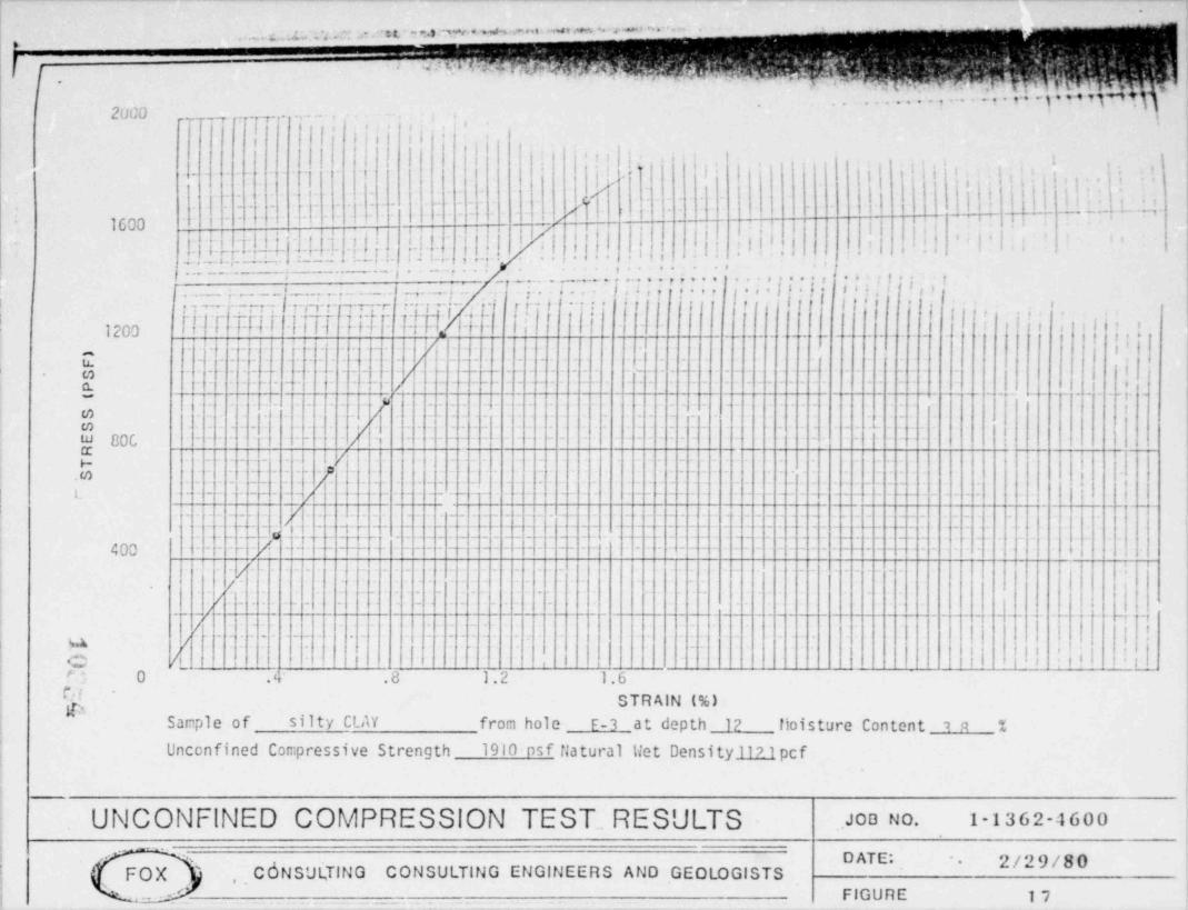
i. Sample of silty C!_AY from hole E-3 at depth 12 lioisture Content 19 % !
| Unconfined Compressive Strength 1910 psf flatural llet Density 117.1 pcfI
| UNCONFINED COMPRESSION TEST.. RESULTS .JOD NO. 1-1362-4600
x . DATE: 2 / <> 9 / 8 0 !1
! (e.
FOX C 6 NSUt, TIN G CONSULTING ENGINEERS AND GEOLOGISTS~'
, ;
: ( .. ' FIGURE 17 |
.
.
n ,.e .. aewm,w,,,:eeksms3sabmh%~
* . . . . . . . ..
(-10,000
-- r- g, q ,, .; ,) ,;;. i ,
~ ~.| | ,,.ii ig ,' f|. . . II
~
~.li I I I _~ .I$~ ~ ~
I~ ~ ~ #
/ .
,,,_ . -- - . _ . j-- ..._ _._.___. _ y . y- -
- i,-- - + - , -p_.._
. . . _ _ . :~ ~ ~ ^ ~ ~ ~ ~
.)!^
|~ ~ ~ ~~ : ~._ ' __ _ .... - _. _ _ _ _ . _ _ _ . . _ _ _ .. .
*- . . / ;
. . . . . ; \',,t*
8 I .!_i. _ _ q i
8,000 - l - - --- - - - ' - - - ~ - - - - - - /j t i tI ! '.
~ ~
1~ ~ ~
'I I
_ : _ i .. : _
{~ { : . . _ _ . _
.;_ _ _ / _ _ _ . _ . _ -.
_
_ _ . . _ _ _ . . . . .. 4 _ _ _ _ . . 7 - _ . . .. - y. , _ . . . . . . .__ . .. .. _ _ . _, ._ _ _ . . , . _ _ _ . - -[~ P :ll.
_{:- -Li.T : l i': -T : ~ ~ ~ ~
:~
Z : .: : . 11: ~.'
: N ~l ~ ~~ - '
: :~
l ~_~
1 .- L 1I/
~I- -
-/ - --- - -~ ~ ~ ~ -~ -Y- ' I .!_ _b.-
6,000 {- - - - - - - - - - - ~ - - - - T - --
j ,.jy__ _ _ _ . . . . . . _ _ jii. . . . . . _ _ . . .
,
, ;_ . . . . _ . . _ . _ .
.g (..~T. . . _
*
,_ , _ . - - - - _ . . .- - - - -.
s
_ _ . q. _ _ . . _ _ _ . - . . . . _ _ _ _ . . _-. . _ . . - - -
_ _ .. _ _ _ . . __ ._ /~~ ~ ~~~ ~ ~ ~ ~ ~ ~
{
-- . ~_ T~
i _ ~. . - . . _ ~. _ _ _ _ _ _ _ - I .
|
~ ~ -
tu 4,000 - - - - -- - -- - f - -- '/. ... _. . ~..__ _ . . ~. . _l*
-
,.
[ - _ - - /-- - - - - - - -
i ;
[- :-- .55 :(.~~5: k _ dhi ~.: : 11 : _ U - d _~_ _ _ : 5 _ . : ZJ. _ . _.- Ed_ _ _ .. ,. . , . .
2,000 h -TI'
R$~ ~ '
I M~
I~
I I~ ~ ~ ~
I~
' ll - I - - - --- I~
j_
1.~
:-
':~ - ~
: EI/.U . : .- : :: : : : : 11 . . . . l : _ : : . :~ ~
: : :~ -
T ' ~
ll! .. 1 :~'~ ~ ~~
_
- - - |i~ ~ ~ ~ ~ ~ -
!
-
:|: ] M k ~
: . : - '-I -. . _ _ . : _ :
~ ~ ~ ~ ~ I. . . _
. : : : : : : _ . _ : - :: ::~
}} : . :: : : :. : _. _ _ _ - _ : :_ - _ . .
- ~
X~, [. o .. . . _ _ ._ . _ _ _ . . _ _ _ _ _ _ . _ _.. . . - |
_
l,,~ ~ ~ {j,t
!! ||!!: . _ .. . . . . . _ . - _ .] } || :
O.2 .4 .6 .8. 1
STRAIN (%) .0 1.2 1.4
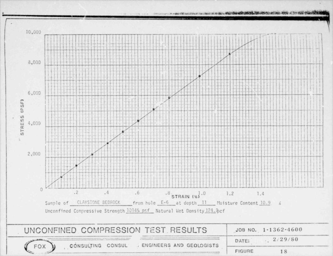
Sample of CLAYST0"E BEDROCK frca hole E-6 at depth 11 floisture Content 10.9_ .4
Unconfined Compressive Strength 10145 psf flatural Het Density 124 4cf
UNCONFINED. COMPRES.SION TEST. RESULTS . JOB N O. , 1-1362-4600
ENGINEERS AND GEOLOGISTS .~
:. 2/29/80DATE; '-
FOX , . CdNSul(TING CONSUL' a' FIGURE 18'
.._ _ _. . _ _ _ . . . _ _ _ _ _ _ _ _ _ _ _ _ _ _
________ ______ - _ _ _ _ . .. _-
.
-
-....m .,~ m.eM;-hamea4edniity. _.
,
20.000., i ;, s , + ,
' ,,,, , -: ., ,'| 8 |
'
r 4 +*| t' - + 8'
e i< , ,
l b' | :| ! ||{ ._L 8t . . ,. _2. !..a. .|. . j/ _. ._ . I i {
. . . _ _ _ . . _ _ . o . . . . }
! ~ l* ' ' ' _16,000 ..___
|1 V_
| .
I~~ ~ ~ ~
-'
*.
4 'g~Y . . _ ; {. 6
-
/.- - ~ ~
~ ' - ' ~
. ' ___.._ 'I _ _; ,___ _____._ _
l. . . Jo / . _: : ~ ' -
: : ~
'i .'-
. . . . _ .
. . . . s. . . . . . .. . . . .
12,000 + / ~ ~ ~ ~ - - ' | '- '
_ . . . [.j f. . :
- ~ ~ ~ ,j :'. .
$ ._
~
:.. . J . _ . . i-
9 - o -- - - -
,__ _
|~
|/| ]|| 'lm.m t / a -
! I ',
o ,
y8,000 .l. i i '/ 1~
' '
|| I'o'
O ' _ ||I'H
. . . . . _ . . . . i L4f . _.__ >[ _ ._ ___._._ _ . _ ___ fI .
~ ~ ~ ' ~ " ~ ~ ~ ~ ~ ~ ~ ~ ' ~ ~ ' ' ' ' '
4,000 ! IM_ . . ~.
~ ' ~ ~ ~ ~ 'g ;
. .
. . 5~
|t. . . _ .,
- 1' '
| c[ . . _ . . . . . - . t
'' '! |_ _ _,
.
_ _ _ __
.,c - _ . _ _ - _. . .__ ..___...
'
. _ __ [
! |||| if|:_j 0
,I | | !
'
t
.4 .8 1.2 1.6 2.0,
STRAIN (%) ;-
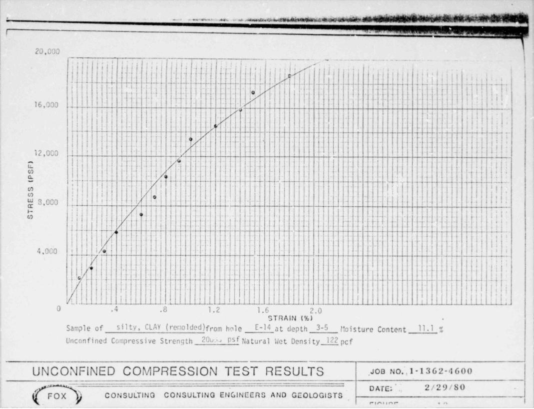
Sample of silty, CLAY (remolded)from hole E-14 at depth 3-5 tbisture Content 11 1 % i
psf atural Wet Density 122 cfUnconfined Compressive Strength 20u L fl p.
|
.
UNCONFINED COMPRESSION TEST RESULTS .aOo tmi.1 -13 6 2-4 6 o o ,
l'
D ATE; 2/29/80 -
' #FOX C ON SULTIN G CONSULTING ENGINEERS AND GEOLOGISTS ,
rin. i n c ,n
_ -_ - . ._- .
-- . _. -- _ _ _ . --
.
.
. ., ,,. , .. - .m As w= n2r * ' '. . , . . - . * - --
.:
,_ , .,
. . . . ,
*6." e *( t *.!r ,e'e't . .,,,g ,,
'I I ii4 i| | i j .
' ' '. !
', ,.
i., .. ,% _ . ..._- . . _ .. , . _..__ _._ _,.__. ,_ . - _ __ _ . - . __ 4_. . , _ .- _ _ _-._.-- _ . ~ ,_ -. - - 4.5 - .
. - -
h.'
. _ . _ . . - .
ji,|.
,
[ ..,i t
a!.g. . . -
16,000 - - -
.
' ',
. i._. 1. . |i ': ,
|- - - -
:|| _lji .
Q _____ _.____ _ .__._.._. ' 3,
- - ~
-
: . . '2-- # ._ p _--__ __L_L i
i
.' w{{i
l !!- _ ~
l
! C | . | _ _ _ _ . . [9_,
- - ,j . *: '.-
12,000 - /. _
2 -
T - . |i|||
S t. __ . }.._ .. _7 - - ~ - -
L: 4
t.e , . ._ ._ . . _ . . - - p j ;- - - - : _w _L'
|. u
__ 4_______ __ _- _ ___._ __ !J. ;.
.
Q j.
/. . _ . . . _ . i@
,
_ .- . . - . -. - A
tu 8,000 ,I . ! i*, ,
H|
|
_ _a' p.xl ''e
tj- - '
. [.|. . . - - - - - _ _ - _ _ ym
, . . . .- '
i
/y . . . _ - - - . i.
-8
L
4,000. Il . _ . - -
g !
f|/-
!-
.,q . 3I
. .! _ .~ !_ Il.' _ _ _: _ _ _ - . . _ _ _ [i . - l i|
l'
j. _. _ . . . . _ . . . .
-||c~ ' ' -
{ .- t ___ .|.
-
i ._ - --_ ___ , . - -- _._ ..___ _ _ - ._ . . ._ _ _ _._. _ ___.- - -
/J^ l i !!ii Ul1 i
O .4 .8 1.2 1.6 2.0STRAIN (%) *
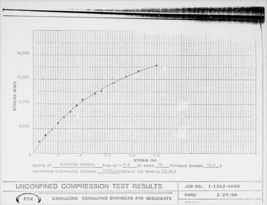
Sample of CLAYSTONE BEDROCK from ho'? P-3 at depth _ 19 Moisture Content 13.3 %Unconfined Compressive Strength 14355 ps fila tural liet Density 136.thcf
;i
|
UNCONFINED COMPRESSION TEST RESULTS .ae No , 1-1362-4600
' DATE: 2/29/80 '
!.'
FOX C ON SULTING CONSULTING ENGINEERS AND GEOLOGISTS !,
Ie ,
It % |'*~
-.
F M FOX & assoc!ATES. INC. |-
g,
i '/ C*
4765 l'.OEPENDENCE sTnFET |'
j ,i I Consult.ing cng:neers and Geolog. tsi - .
is ..~ Ear nccE cow =m oeu I'g /--
,
(303) 42 5 5578 - FMFCX, , ._
|
,
*
.
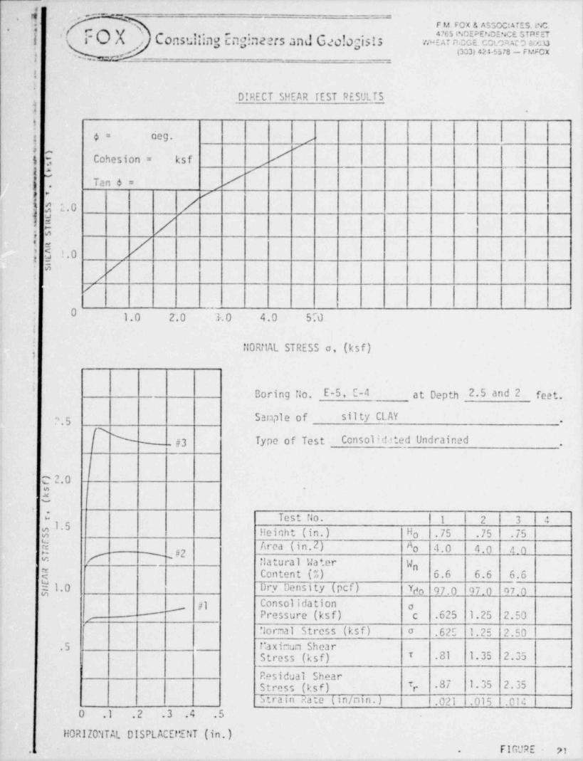
DIRECT SHEAR TEST RESULTSI .
1g 4= ceg. ,
3 Cohesion = ksf /,-
> s ,
$ Tan 6 = /,
e /-
s E.0 /;
: : /,0u, ,..
5 //'
/
0-
1.0 2.0 3.0 4.0 570
fl0RitAL STRESS o, (ksf)
Boring flo. E-5, E-4 at Depth 2.5 and 2 fee t.
'' . 5 Sample of silty CLAY,
/s #3 Type of Test Consolid.ited Undrained% ,,
C 2.0I; .
-.
C Test No. | 1 2 3 |4:
1$
'5Heiqht (in.) fi .75 .75 .75o
N Area (in.2) No 4.0 4.0 a0' #2- * -
% -
| "- |latural Water W, nQ Content (%) 6.6 6.6 6.6
$1.0 Dry Density (pcf) Ydo 97.0 47.0 97.0"1 Consolidation2 o'
Pressure (ksf) c .625 1.25 2.50--,
'
flormal Stress (ksf) o .62E 1.25 2.50.5 i:aximun Shear
T .81 1.35 2.35Stress (ksf)_
Residual ShearT .87 1.35 2.35Stress (ksf) r
5 train Rate (in/nin.) .021 1.015 |.01c0 .1 .2 .3 .4 .5
HORIZ0?lTAL DISPLACEttENT (in.)FIGURE 21., .
. 1
.
-- - . . - . .......- .= = . . - . . . . -
4
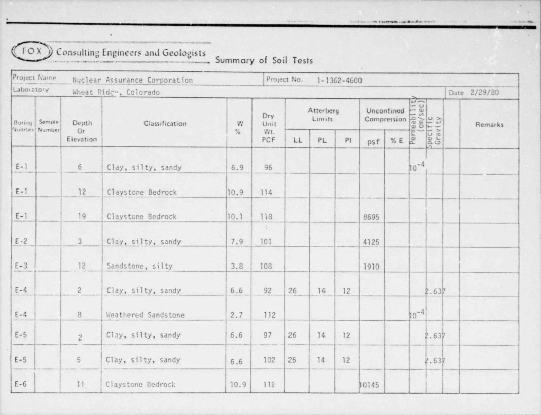
FO X 'i Consulting Engineers and Geologists(_ Summary of Soil Tests
Project Name riuglear Assurance Corporation Pr ject No. 1-1362-4600Labor atory Wheat Ridga, Colorado Date 2/29/80
UuAtterberg Unconfined - ce
.h Remarks" *" "
0<>riou sa m >t e Depth Classification W itNumtsce tJu mber Or % Wt. E~ U$
Elevation PCF LL PL PI psf %E s' E5
E-l 6 Clay, silty, sandy 6.9 96 10-4
E-1 12 Claystone Bedrock 10.9 114
E-1 19 Claystone Bedrock 10.1 118 8695
E-2 3 Clay, silty, sand _y 7.9 101 4125
E-3 12 Sandstone, silty 3.8 108 1910
E-4 2 Clay, silty, sandy 6.6 92 26 14 12 ;?.63 7
E-4 8 Weathered Sandstone 2.7 112 10-4.
E-5 2 Clay, silty, sandy 6.6 97 26 14 12 2.63 7
_ _ _ . . _ _ -_ . _
E-5 5 Clay, silty, sandy 6.6 102 26 14 12 ;?.63 7
E-6 11_ Claystone Bedrock 10.9 112 10145
_ _ _ _ _ _ _ - _ _
. . ...... ._ . ... . _ . m . . - . . . . .. .
,
.
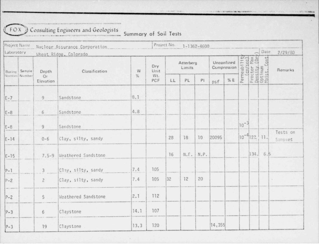
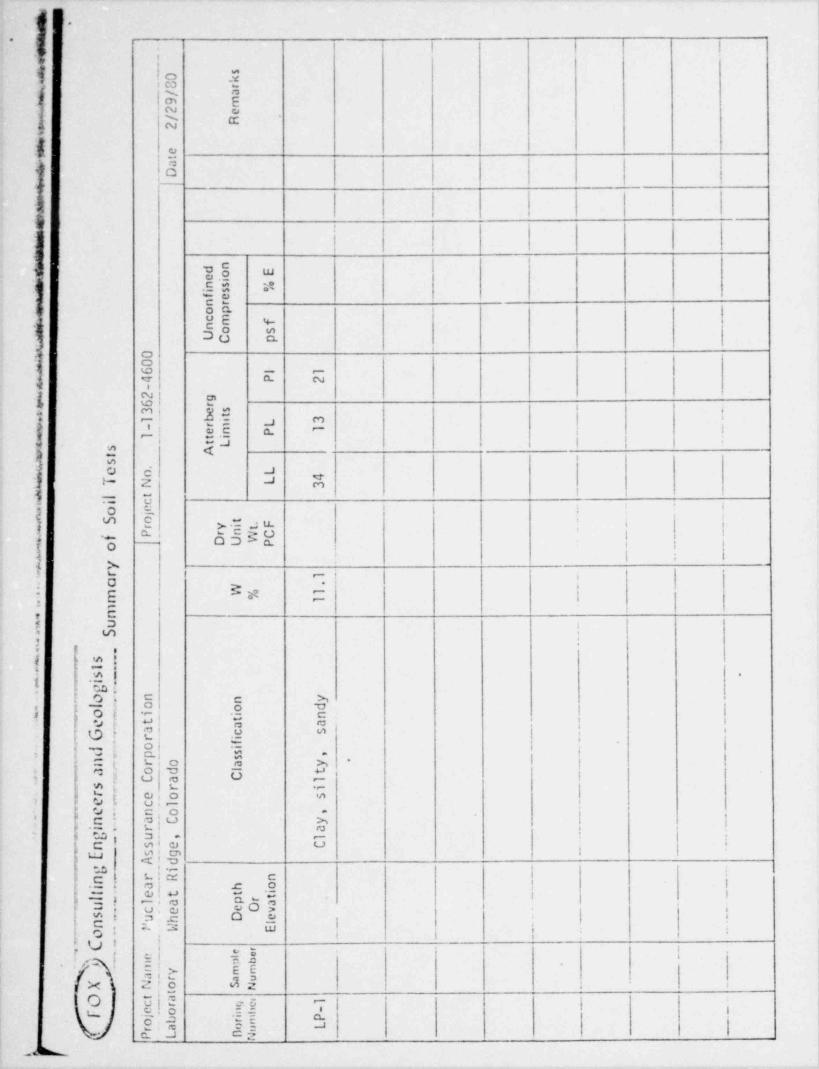
OFOX , Consulting Engineers and Geologists. _._ Summary of Soil Tests
Project Name flucl ea r_AS s urance _Co rpo ra tiOO_._____ _____._. . ..___ __ Project No. 1-1362-4600 __ __
Date 2/29/80Laboratory t| heat Ridge. Colorado - ?un x L'
Atterberg Unconfined IE SE aDry Limits Compression EE t- >>E
norion sa mpte Depth Classification W Unit @8 S.g g RemarksNumis. s PJ u mbe r Or % Wt. E" 8E !;.g
._
%E 2 d- /J g.2Elevation PCF LL PL PI psf
E-7 9 Sandstone 8.1
E-8 6 Sandstone 4.8
-3E-8 9 Sandstone 10
__ __
Tests on-4
E-14 0-6 Clay, silty, sandy 28 18 10 20095 10 122. 11.Sc ies
E-15 7.5-9 Weathered Sandstone 16 fl . f . N.P. 134. 6. 5
P-1 3 Clay, silty, sandy 7.4 105
P-2 2 Clay, silty, sandy 7.4 105 32 12 20 .
__ __
_,
P-2 5 Weathered Sand' stone 2.1 112__ _ _ _ _
_ .. ._
P-3 6 Claystone 14.1 107_. - - _ . . . . _
P-3 19 Claystone 13.3 120 14,355
.___ ________ _
m.
s. s0 k8 r./ a
= 9 m2 e/ R
w 2
+ et
a
m.D
emmm. nn d Eoe i
mins %sf enropcm f
+ n o sU C p
.0-
x 06 l 1
4 P 2e. -
2 g6 r
+ 3 estbi L 3. 1
ntr- m 1
1 t iPe
t Ls As
u. .e o. L4
t N L 3
s. l.i ct
o e *
n Sj
o tr Yi .F W
e
te
_- O'UnWC -PfP wo
- W
4y_ ' 6
,. r '
1
aW %
."
m1
W1,.
m.
u *.
.S *
*
..
.
-*- s
t .
-s .-
.
- i
g. --
o n n y
le-o o d. . o i
it *n
. - t aaG, r ic s
"
**a **f*
- o i
*
d-. - s ,p6
*sn r o a y *.
.- *
a o d l t *
. 8'C *-
e-N'C a. l
s r i
N- r e o s-
9'c lS- e. n o ,
n a C y N *
.
- M.'
. - i. r a M.
- g. u G, l *n. s e C D
_ s g h
G
E_ A d. g- i *
r R n *
n ._ o M.
, ._ l
.a h
iti
6 6e t t. t
l a p r
_. u. eOa e'c e v
e m_. n 'u h D les e
W E 6
4. l. o. h6 _
e _
. .C,lp b
_.
e_r
__e- e.
/ m mm ._y
a r a u .
_ X N o sn _.eg
_
ta ,1o t
mc r gew
oinb -e of j
t t m P e;
Lr a o uP L nN
s '
!-
.
i
TABLE II
FIELO PERMEABILITY TEST RESULTS
:4 HOLE DIAMETER DEPTH OF P ER.''.E AB IL ITY sj !!0. OF CASIt:G TEST (FT.) ELEVATI0ti t'ATERIAL TYPE (ca/sec)
'
y\f E-1 4" 18.5 5085.5 CLAYST0 tie 4.3 x 10⁻⁷ !
e
U E-2 4" 18.7 5086.8 Interbedded SANDST0 tie- 6.4 x 10⁻⁷$ CLAYST0 tie! E-3 4" 17.8 5088.2 CLAYST0t;E 6.3 x 10⁻⁷|8 E-4 4" 12.1 5092.4 Weathered SAf40STO.'JE 4.1 x 10⁻⁴
| E-5 4" 13.7 5091.8 CLAYST0 tie 8.0 x 10⁻⁷E-6 4" 13.0 5093.5 Interbedded CLAYSTCt;E & 8.6 x 10⁻⁷
.
SAT 1DSTONEj E-7 4" 18.8 5087.7 CLAYSTONE 8.7 x 10⁻⁷i E-8 4" 18.2 5088.3 Interbedded CLAYSTONE & 2.5 x 10⁻⁶i SAT 10ST0t;E~
E-9 4" 18.2 5088.8 CLAYSTONE 1.2 x 10⁻⁶E-10 6" 8.0 5097.0 CLAY 2.8 x 10⁻⁶,
'
E-ll 6" 6.1 5098.9 CLAY 3.6 x 10⁻⁶E-12 6" 8.2 5098.3 CLAY 4.9 x 10⁻⁶,
E-13 6" 8.6 5096.9 CLAY 4.2 x 10⁻⁶E-14 6" 4.8 5101.2 CLAY 7.2 x 10⁻⁶E-15 6" 7.9 5099.1 CLAY 3.2 x 10⁻⁶
|
|
|!
|
,
9
4 L
-,
1*
i*
;!
TABLE III
4PERCOLATION TEST RESULTSx
-
;
{ H0LE DEPTH S0Il TYPE PERCOLATION RATE_ NUMBER (inches) (lower 1 foot) (min / inch)
1: L-1 45 CLAY, silty, sandy 11i
L-2 43 CLAY, silty, sandy 7
} L ') 43 CLAY, silty, sandy 6it L-4 42 CLAY, silty, sandy 16 i
i
f,':
I:; * NOTE: Calculated results on the basis of 2 hour tests. )5 j
1!
( ,
-
|
i i
), -
l*
l
|
|
|
c,
|. - . . . . - - - - . - - - . _ _ . _ . _ . .._.__ _ _ _ _ _ _ . , _ _ _ ,
~3~=~*c*~~~;-~ -9-