i-769p firelock nxt™ preaction...
TRANSCRIPT

HANG THESE INSTRUCTIONS ON THE INSTALLED VALVE FOR EASY FUTURE REFERENCE
WARNING
�•� Failure�to�follow�instructions�and�warnings�can�cause�product�failure,�resulting�in�serious�personal�injury�and�property�damage.
•� Read�and�understand�all�instructions�before�attempting�to�install�any�Victaulic�piping�products.
•� Wear�safety�glasses,�hardhat,�and�foot�protection.
•� Save�this�installation,�maintenance,�and�testing�manual�for�future��reference.
If�you�need�additional�copies�of�any�literature,�or�if�you�have�any��questions�concerning�the�safe�installation�and�operation�of�this�product,�contact�Victaulic,�P.O.�Box�31,�Easton,�PA�18044-0031,�USA,�Telephone:�1-800�PICK�VIC,�e-mail:�[email protected].
WARNING
FireLock�NXT™�Preaction�ValveSERIES 769 NON-INTERLOCKED,�PNEUMATIC�RELEASE�WITH�SERIES�776�LOW-PRESSURE�ACTUATOR NON-INTERLOCKED,�PNEUMATIC/ELECTRIC�RELEASE�WITH�SERIES�776�LOW-PRESSURE�ACTUATOR�AND�SERIES�753-E�SOLENOID�VALVE SINGLE-INTERLOCKED,�PNEUMATIC�RELEASE�WITH�SERIES�776�LOW-PRESSURE�ACTUATOR SINGLE-INTERLOCKED,�ELECTRIC�RELEASE�WITH�SERIES�753-E�SOLENOID�VALVE DOUBLE-INTERLOCKED,�ELECTRIC�(ELECTRIC-PNEUMATIC/ELECTRIC)�RELEASE�WITH�SERIES�753-E�SOLENOID�VALVE
I-769PINSTALLATION,�MAINTENANCE,�AND�TESTING�MANUAL
www.victaulic.comVICTAULIC IS A REGISTERED TRADEMARK OF VICTAULIC COMPANY. © 2007 VICTAULIC COMPANY. ALL RIGHTS RESERVED. PRINTED IN THE USA.
REV_D

TABLE�OF�CONTENTSHazard Identification . . . . . . . . . . . . . . . . . . . . . . . . . . . . . . . . . . . . . . 1
Installer Safety Instructions . . . . . . . . . . . . . . . . . . . . . . . . . . . . . . . . . 2General . . . . . . . . . . . . . . . . . . . . . . . . . . . . . . . . . . . . . . . . . . . . . . 2Maintenance and Testing. . . . . . . . . . . . . . . . . . . . . . . . . . . . . . . . . 2
Introduction . . . . . . . . . . . . . . . . . . . . . . . . . . . . . . . . . . . . . . . . . . . . . 3
Trim Dimensions . . . . . . . . . . . . . . . . . . . . . . . . . . . . . . . . . . . . . . . . . 3
Exploded View Drawing – Trim Components . . . . . . . . . . . . . . . . . . . . 4
Exploded View Drawing – Trim Components . . . . . . . . . . . . . . . . . . . . 5
Exploded View Drawing – Trim Components . . . . . . . . . . . . . . . . . . . . 6
Exploded View Drawing – Trim Components . . . . . . . . . . . . . . . . . . . . 7
Exploded View Drawing – Internal Valve Components. . . . . . . . . . . . . . 8
Section View Drawing and Description – Series 776 Low-Pressure Actuator . . . . . . . . . . . . . . . . . . . . . . . . . . 9
Section View Drawing and Description – Series 746-LPA Dry Accelerator. . . . . . . . . . . . . . . . . . . . . . . . . . . 10
Air Supply Requirements . . . . . . . . . . . . . . . . . . . . . . . . . . . . . . . . . . 11Compressor Sizing . . . . . . . . . . . . . . . . . . . . . . . . . . . . . . . . . . . . . 11Base or Riser-Mounted Air Compressors . . . . . . . . . . . . . . . . . . . . 11Shop Air or Tank-Mounted Air Compressors. . . . . . . . . . . . . . . . . . 11Victaulic Series 757 Regulated Air Maintenance
Trim Assembly (AMTA) Option . . . . . . . . . . . . . . . . . . . . . . . . . . 11Victaulic Series 757P Air Maintenance Trim Assembly
(AMTA) with Pressure Switch Option . . . . . . . . . . . . . . . . . . . . . 12Compressor Requirements and Settings for
Series 769 FireLock NXT Preaction Valves Installed with Series 746-LPA Dry Accelerators . . . . . . . . . . . . . 12
Settings for Air Supervisory Pressure Switches and Alarm Pressure Switches . . . . . . . . . . . . . . . . . . . . . . . . . . 12
Remote System Test Valve Requirements. . . . . . . . . . . . . . . . . . . . 12
Important Installation Information . . . . . . . . . . . . . . . . . . . . . . . . . . . 13
Valve/Trim Installation . . . . . . . . . . . . . . . . . . . . . . . . . . . . . . . . . . . . 13Compression Fitting and Tube Installation . . . . . . . . . . . . . . . . . . . 14
Hydrostatic Testing . . . . . . . . . . . . . . . . . . . . . . . . . . . . . . . . . . . . . . 14
Placing the System in Service . . . . . . . . . . . . . . . . . . . . . . . . . . . . . . 15
External Inspection . . . . . . . . . . . . . . . . . . . . . . . . . . . . . . . . . . . . . . 21Weekly Inspection . . . . . . . . . . . . . . . . . . . . . . . . . . . . . . . . . . . . . 21Monthly Inspection . . . . . . . . . . . . . . . . . . . . . . . . . . . . . . . . . . . . 21
Required Tests. . . . . . . . . . . . . . . . . . . . . . . . . . . . . . . . . . . . . . . . . . 22Main Drain Test . . . . . . . . . . . . . . . . . . . . . . . . . . . . . . . . . . . . . . . 22Water Flow Alarm Test . . . . . . . . . . . . . . . . . . . . . . . . . . . . . . . . . . 24Water Level and Low Air Alarm Tests . . . . . . . . . . . . . . . . . . . . . . . 25
Required Operational (Trip) Tests. . . . . . . . . . . . . . . . . . . . . . . . . . . . 29Partial Operational (Trip) Test. . . . . . . . . . . . . . . . . . . . . . . . . . . . . 29Full Operational (Trip) Test . . . . . . . . . . . . . . . . . . . . . . . . . . . . . . . 31
Required Internal Inspection . . . . . . . . . . . . . . . . . . . . . . . . . . . . . . . 33
Maintenance . . . . . . . . . . . . . . . . . . . . . . . . . . . . . . . . . . . . . . . . . . . 36Removing and Replacing the Clapper Seal. . . . . . . . . . . . . . . . . . . 36Removing and Replacing the Clapper Assembly. . . . . . . . . . . . . . . 38Installing the Cover Plate Gasket and Cover Plate. . . . . . . . . . . . . . 40Removing and Replacing the Diaphragm Assembly . . . . . . . . . . . . 41Replacing the Strainer Screen for
Series 776 Low-Pressure Actuators . . . . . . . . . . . . . . . . . . . . . . 42
Troubleshooting – Series 776 Low-Pressure Actuator . . . . . . . . . . . . . 43
Troubleshooting – Series 753-E Solenoid Valve . . . . . . . . . . . . . . . . . 43
Troubleshooting – Series 746-LPA Dry Accelerator. . . . . . . . . . . . . . . 43
Troubleshooting – System . . . . . . . . . . . . . . . . . . . . . . . . . . . . . . . . . 44
HAZARD IDENTIFICATION
Definitions for identifying the various hazard levels are provided below. When you see this symbol, be alert to the possibility of personal injury. Carefully read and fully u nderstand the message that follows.
WARNING
�The�use�of�the�word�“WARNING”�identifies�the�presence�•�of�hazards�or�unsafe�practices�that�could�result�in�death�or��serious�personal�injury�if�instructions,�including�recommended�precautions,�are�not�followed.
CAUTION
The�use�of�the�word�“CAUTION”�identifies�possible�hazards�or�•�unsafe�practices�that�could�result�in�personal�injury�and�prod-uct�or�property�damage�if�instructions,�including�recommended��precautions,�are�not�followed.
NOTICE
The�use�of�the�word�“NOTICE”�identifies�special�instructions�•�that�are�important�but�not�related�to�hazards.
REV_D
FireLock�NXT™�Preaction�ValveSERIES 769
I-769PINSTALLATION,�MAINTENANCE,�AND�TESTING�MANUAL
www.victaulic.comVICTAULIC IS A REGISTERED TRADEMARK OF VICTAULIC COMPANY. © 2007 VICTAULIC COMPANY. ALL RIGHTS RESERVED. PRINTED IN THE USA.
I-769P_1

INSTALLER SAFETY INSTRUCTIONS
WARNING
�An�experienced,�trained�installer�must�install�this�product�in�accordance�with�all�instructions.�These�•�i�nstructions�contain�important�information.
Depressurize�and�drain�the�piping�system�before�attempting�to�install,�remove,�adjust,�or�maintain�any�•�Victaulic�piping�products.
Failure�to�follow�these�instructions�can�cause�product�failure,�resulting�in�serious�personal�injury�and/or��property�damage.
GENERAL
Read�and�understand�all�instructions�and�refer�to�the�trim�1. �diagrams�before�proceeding�with�the�installation,�maintenance,�and�testing�of�this�Victaulic�Series�769�FireLock�NXT�Preaction�Valve.
Inspect�the�shipment.2. Make sure all components are included in the shipment and that all necessary tools are available for installa-tion.
Use�only�recommended�accessories.3. Accessories and equipment that are not approved for use with this valve may cause improper system operation.
Wear�safety�glasses,�hardhat,�foot�protection,�and�hearing�4. protection. Wear hearing protection if you are exposed to long periods of noisy job-site operations.
Prevent�back�injury.5. Larger and pre-trimmed valves are heavy and require more than one person or mechanical lifting equipment to position and install the assembly. Always practice proper lifting techniques.
Avoid�using�electrically�powered�tools�in�dangerous�environ-6. ments. When using electrically powered tools for installation, make sure the area is moisture-free. Keep the work area well lit, and allow enough space to accommodate proper installation of the valve, trim, and accessories.
Watch�for�pinch�points.7. Do not place fingers under the valve body where they could be pinched by the weight of the valve. Use c aution around spring-loaded components (i.e. clapper assembly).
Keep�work�areas�clean.8. Cluttered areas, benches, and slippery floors can create hazardous working conditions.
PROTECT�THE�SYSTEM�FROM�FREEZING�CONDITIONS.�THE�9. VALVE�AND�SUPPLY�PIPING�MUST�BE�PROTECTED�FROM�FREEZING�TEMPERATURES�AND�MECHANICAL�DAMAGE.
IF�THE�INLET�WATER�SUPPLY�IS�INTERRUPTED�FOR�ANY�10. REASON,�AND�SYSTEM�SUPPLY�PRESSURE�TO�THE�VALVE�DECREASES,�MAKE�SURE�THE�DIAPHRAGM�CHARGE�LINE�IS�FULLY�PRESSURIZED�BEFORE�PLACING�THE�SYSTEM�BACK�IN�SERVICE.
MAINTENANCE�AND�TESTING
Notify�the�authority�having�jurisdiction.1. Always notify the author-ity having jurisdiction before performing any maintenance that eliminates the fire protection provided by the system.
Follow�NFPA�requirements�for�system�testing�and�inspection�2. s�chedules. The building owner or their representative is responsi-ble for inspecting the system in accordance with current NFPA-25 requirements or in accordance with the requirements of the local authority having jurisdiction (whichever is more stringent).
Depressurize�and�drain�the�system�completely�before�performing�3. any�maintenance. Water under pressure can cause the cover plate to blow off during removal if the system is not depressurized and drained completely.
Protect�the�valve�from�freezing�temperatures,�foreign�matter,�4. and�corrosive�atmospheres. Any condition that might degrade the system or affect system performance must be avoided.
I-769P_2
FireLock�NXT™�Preaction�ValveSERIES 769
I-769PINSTALLATION,�MAINTENANCE,�AND�TESTING�MANUAL
www.victaulic.comVICTAULIC IS A REGISTERED TRADEMARK OF VICTAULIC COMPANY. © 2007 VICTAULIC COMPANY. ALL RIGHTS RESERVED. PRINTED IN THE USA.
REV_D

INTRODUCTIONThe following instructions are a guide for proper installation of Victaulic Series 769 FireLock NXT Preaction Valves. These instructions involve pipe that is properly prepared and grooved in accordance with current Victaulic specifications.
NOTICEDrawings�and/or�pictures�in�this�manual�may�be�exaggerated�for�clarity.•�
This�product�and�this�installation,�maintenance,�and�testing�manual�contain�trademarks,�copyrights,�and/or�patented�features�that�are�the�•�exclusive�property�of�Victaulic.
TRIM�DIMENSIONSTHE�4-INCH/114.3-MM�CONFIGURATION�IS�SHOWN�BELOW.�1�½�–�2-INCH/48.3�–�60.3-MM�CONFIGURATIONS�CONTAIN�¾-INCH/19-MM�DRAIN�VALVES.
2�½�–�3-INCH/73.0�–�88.9-MM�CONFIGURATIONS�CONTAIN�1�¼-INCH/31-MM�DRAIN�VALVES.�4�–�8-INCH/114.3�–�219.1-MM�CONFIGURATIONS�CONTAIN�2-INCH/50-MM�DRAIN�VALVES.
A
J
*A1
B*B1
G
F
D*D1
CFull Open
K
*E1
E
H
Size Dimensions�–�inches/mmAprx.�Weight�Ea.�
lbs/kg
Nominal�Size
inchesmm
Actual�Out.�Dia.�inchesmm A A1* B B1* C D D1* E E1* F G H J K
Without�Trim
With�Trim
1½ 1.900 9.00 16.43 28.25 40.50 13.75 16.00 — 5.25 8.50 9.50 22.25 3.04 9.17 6.98 16.7 43.040 48.3 228.60 417.32 717 1028 349 406 133 215 241 565 77.21 232.91 177.29 7.6 19.52 2.375 9.00 16.43 28.25 40.50 13.75 16.00 — 5.25 8.50 9.50 22.25 3.04 9.17 6.98 17.0 43.0
50 60.3 228.60 417.32 717 1028 349 406 133 215 241 565 77.21 232.91 177.29 7.7 19.52 ½ 2.875 12.61 16.50 32.25 44.25 13.50 16.00 17.50 5.25 9.00 9.25 21.25 3.90 10.50 6.93 41.0 65.065 73.0 320.29 419.10 819 1123 342 406 444 133 228 234 539 99.06 266.70 176.02 18.7 29.5
76.1 mm 3.000 12.61 16.50 32.25 44.25 13.50 16.00 17.50 5.25 9.00 9.25 21.25 3.90 10.50 6.93 41.0 65.076.1 320.29 419.10 819 1123 342 406 444 133 228 234 539 99.06 266.70 176.02 18.7 29.5
3 3.500 12.61 16.50 32.25 44.25 13.50 16.00 17.50 5.25 9.00 9.25 21.25 3.90 10.50 6.93 41.0 65.080 88.9 320.29 419.10 819 1123 342 406 444 133 228 234 539 99.06 266.70 176.02 18.7 29.54 4.500 15.03 19.78 33.25 45.50 15.00 15.75 20.50 5.50 9.00 10.75 20.75 6.25 9.62 8.46 59.0 95.0
100 114.3 381.76 502.41 844 1155 381 400 520 139 228 273 527 158.75 244.34 214.88 26.7 43.0
165.1 mm 6.500 16.00 22.00 33.50 45.75 15.50 17.00 22.00 6.00 8.50 11.50 20.00 6.20 9.62 8.84 80.0 116.0165.1 406.40 558.80 850 1162 393 431 558 152 215 292 508 157.48 244.34 224.53 36.2 52.6
6 6.625 16.00 22.00 33.50 45.75 15.50 17.00 22.00 6.00 8.50 11.50 20.00 6.20 9.62 8.84 80.0 116.0150 168.3 406.40 558.80 850 1162 393 431 558 152 215 292 508 157.48 244.34 224.53 36.2 52.6
8 8.625 17.50 22.94 33.50 45.50 16.75 20.00 25.25 7.00 8.75 12.75 18.50 6.05 9.40 10.21 122.0 158.0200 219.1 444.50 582.67 850 1155 425 508 641 177 222 323 469 153.67 238.76 259.33 55.3 71.6
NOTES:The drawings shown above reflect the single-interlocked, pneumatic release trim with Series 776 Low-Pressure Actuator. In addition, these dimensions can be applied to single-interlocked, pneumatic release; non-interlocked, pneumatic/electric release; single-interlocked, electric release; and double-interlocked, electric (electric-pneumatic/electric) release trim.The “A” dimension coupling is not shown for clarity.Components shown as dotted lines denote optional equipment* Measurements denoted with an asterisk take optional equipment into accountOptional drain connection kit is shown for reference and takeout dimensions.
REV_D
FireLock�NXT™�Preaction�ValveSERIES 769
I-769PINSTALLATION,�MAINTENANCE,�AND�TESTING�MANUAL
www.victaulic.comVICTAULIC IS A REGISTERED TRADEMARK OF VICTAULIC COMPANY. © 2007 VICTAULIC COMPANY. ALL RIGHTS RESERVED. PRINTED IN THE USA.
I-769P_3

EXPLODED�VIEW�DRAWING�–�TRIM�COMPONENTSSERIES�769�FIRELOCK�NXT�PREACTION�VALVE�–�NON-INTERLOCKED,�PNEUMATIC�RELEASE�TRIM� VNIIPO (OPTIONAL�ACCESSORIES�ALSO�SHOWN)
From WaterSupply
2
3
1
11
20
22
24
14
13
21
16
19
21
17
18
21
15
6
10
2312
8
4
7
9
From SystemAir Feed
To System
To PilotLine
5
ALocation
A
To DripCup
Location
A
To DripCup
Location
A
To DripCup
Location
Bill of Materials 1 Series 769 FireLock NXT Preaction Valve 2 FireLock Rigid Coupling (Optional/Sold Separately – Comes Standard when VQR Assembly is Ordered) 3 Water Supply Main Control Valve (Optional/Sold Separately – Comes Standard when VQR Assembly is Ordered) 4 Drain Swing Check Valve 5 Drip Cup with Cap 6 Alarm Pressure Switch (Optional/Sold Separately – Comes Standard when VQR Assembly is Ordered) 7 Series 729 Drip Check Valve 8 Diaphragm-Charge-Line Ball Valve (Normally Open) 9 3-in-1 Strainer/Check/Restrictor Assembly 10 Series 760 Water Motor Alarm (Optional/Sold Separately) 11 Alarm Test Ball Valve 12 Diaphragm-Charge-Line Pressure Gauge (0-300 psi/0-2068 kPa/0-20.7 Bar) 13 Series 749 Auto Drain 14 Series 776 Low-Pressure Actuator 15 Air Manifold 16 Air Supervisory Pressure Switch (Optional/Sold Separately – Comes Standard when VQR Assembly is Ordered) 17 System Pressure Gauge (0-80 psi/0-552 kPa/0-5.5 Bar with Retard) 18 Water Supply Main Drain Valve - Flow Test 19 Water Supply Pressure Gauge (0-300 psi/0-2068 kPa/0-20.7 Bar) 20 Drain Connection Kit (Optional/Sold Separately – Comes Standard when VQR Assembly is Ordered) 21 Gauge Valve 22 System Main Drain Valve 23 Series 755 Manual Pull Station 24 Series 748 Ball Check Valve
Note 1
NOTE�1: Connection point for the Series 75D Water Column Device Kit
For information regarding installation of the Series 75B Supplemental Alarm Device or the Series 7C7 Air Maintenance/Compressor Assembly (not shown), refer to the instructions supplied with the product.
I-769P_4
FireLock�NXT™�Preaction�ValveSERIES 769
I-769PINSTALLATION,�MAINTENANCE,�AND�TESTING�MANUAL
www.victaulic.comVICTAULIC IS A REGISTERED TRADEMARK OF VICTAULIC COMPANY. © 2007 VICTAULIC COMPANY. ALL RIGHTS RESERVED. PRINTED IN THE USA.
REV_D
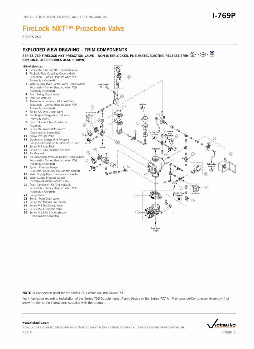
EXPLODED�VIEW�DRAWING�–�TRIM�COMPONENTSSERIES�769�FIRELOCK�NXT�PREACTION�VALVE�–�NON-INTERLOCKED,�PNEUMATIC/ELECTRIC�RELEASE�TRIM� VNIIPO (OPTIONAL�ACCESSORIES�ALSO�SHOWN)
2
3
From WaterSupply
1
11
20
22
24
14
13
21
16
19
21
17
18
21
15
6
10
23
26
1225
8
4
7
9
From SystemAir Feed
To System
5
ALocation
A
To Drip CupLocation
A
To Drip CupLocation
A
To Drip CupLocation
A
To DripCup
Location
Bill of Materials 1 Series 769 FireLock NXT Preaction Valve 2 FireLock Rigid Coupling (Optional/Sold Separately – Comes Standard when VQR Assembly is Ordered) 3 Water Supply Main Control Valve (Optional/Sold Separately – Comes Standard when VQR Assembly is Ordered) 4 Drain Swing Check Valve 5 Drip Cup with Cap 6 Alarm Pressure Switch (Optional/Sold Separately – Comes Standard when VQR Assembly is Ordered) 7 Series 729 Drip Check Valve 8 Diaphragm-Charge-Line Ball Valve (Normally Open) 9 3-in-1 Strainer/Check/Restrictor Assembly 10 Series 760 Water Motor Alarm (Optional/Sold Separately) 11 Alarm Test Ball Valve 12 Diaphragm-Charge-Line Pressure Gauge (0-300 psi/0-2068 kPa/0-20.7 Bar) 13 Series 749 Auto Drain 14 Series 776 Low-Pressure Actuator 15 Air Manifold 16 Air Supervisory Pressure Switch (Optional/Sold Separately – Comes Standard when VQR Assembly is Ordered) 17 System Pressure Gauge (0-80 psi/0-552 kPa/0-5.5 Bar with Retard) 18 Water Supply Main Drain Valve - Flow Test 19 Water Supply Pressure Gauge (0-300 psi/0-2068 kPa/0-20.7 Bar) 20 Drain Connection Kit (Optional/Sold Separately – Comes Standard when VQR Assembly is Ordered) 21 Gauge Valve 22 System Main Drain Valve 23 Series 755 Manual Pull Station 24 Series 748 Ball Check Valve 25 Series 753-E Solenoid Valve 26 Series 746-LPA Dry Accelerator (Optional/Sold Separately)
Note 1
NOTE�1: Connection point for the Series 75D Water Column Device Kit
For information regarding installation of the Series 75B Supplemental Alarm Device or the Series 7C7 Air Maintenance/Compressor Assembly (not shown), refer to the instructions supplied with the product.
REV_D
FireLock�NXT™�Preaction�ValveSERIES 769
I-769PINSTALLATION,�MAINTENANCE,�AND�TESTING�MANUAL
www.victaulic.comVICTAULIC IS A REGISTERED TRADEMARK OF VICTAULIC COMPANY. © 2007 VICTAULIC COMPANY. ALL RIGHTS RESERVED. PRINTED IN THE USA.
I-769P_5

EXPLODED�VIEW�DRAWING�–�TRIM�COMPONENTSSERIES�769�FIRELOCK�NXT�PREACTION�VALVE�–�SINGLE-INTERLOCKED,�PNEUMATIC�RELEASE�TRIM� VNIIPO (OPTIONAL�ACCESSORIES�ALSO�SHOWN)
ALocation
2
3
From WaterSupply
1
11
20
22
14
13
21
16
19
21
17
18
5
21
15
6
10
23
25
12
8
4
7
9
To PilotLine
From SystemAir Feed
To System
24
A
To DripCup
Location
A
To DripCup
Location
A
To Drip CupLocation
Bill of Materials 1 Series 769 FireLock NXT Preaction Valve 2 FireLock Rigid Coupling (Optional/Sold Separately – Comes Standard when VQR Assembly is Ordered) 3 Water Supply Main Control Valve (Optional/Sold Separately – Comes Standard when VQR Assembly is Ordered) 4 Drain Swing Check Valve 5 Drip Cup with Cap 6 Alarm Pressure Switch (Optional/Sold Separately – Comes Standard when VQR Assembly is Ordered) 7 Series 729 Drip Check Valve 8 Diaphragm-Charge-Line Ball Valve (Normally Open) 9 3-in-1 Strainer/Check/Restrictor Assembly 10 Series 760 Water Motor Alarm (Optional/Sold Separately) 11 Alarm Test Ball Valve 12 Diaphragm-Charge-Line Pressure Gauge (0-300 psi/0-2068 kPa/0-20.7 Bar) 13 Series 749 Auto Drain 14 Series 776 Low-Pressure Actuator 15 Air Manifold 16 Air Supervisory Pressure Switch (Optional/Sold Separately – Comes Standard when VQR Assembly is Ordered) 17 System Pressure Gauge (0-80 psi/0-552 kPa/0-5.5 Bar with Retard) 18 Water Supply Main Drain Valve - Flow Test 19 Water Supply Pressure Gauge (0-300 psi/0-2068 kPa/0-20.7 Bar) 20 Drain Connection Kit (Optional/Sold Separately – Comes Standard when VQR Assembly is Ordered) 21 Gauge Valve 22 System Main Drain Valve 23 Series 755 Manual Pull Station 24 Series 748 Ball Check Valve 25 Series 746-LPA Dry Accelerator (Optional/Sold Separately)
Note 1
NOTE�1: Connection point for the Series 75D Water Column Device Kit
For information regarding installation of the Series 75B Supplemental Alarm Device or the Series 7C7 Air Maintenance/Compressor Assembly (not shown), refer to the instructions supplied with the product.
I-769P_6
FireLock�NXT™�Preaction�ValveSERIES 769
I-769PINSTALLATION,�MAINTENANCE,�AND�TESTING�MANUAL
www.victaulic.comVICTAULIC IS A REGISTERED TRADEMARK OF VICTAULIC COMPANY. © 2007 VICTAULIC COMPANY. ALL RIGHTS RESERVED. PRINTED IN THE USA.
REV_D

EXPLODED�VIEW�DRAWING�–�TRIM�COMPONENTSSERIES�769�FIRELOCK�NXT�PREACTION�VALVE�–�SINGLE-INTERLOCKED,�ELECTRIC�RELEASE�TRIM SERIES�769�FIRELOCK�NXT�PREACTION�VALVE�–�DOUBLE-INTERLOCKED,�ELECTRIC�RELEASE�(ELECTRIC-PNEUMATIC/ELECTRIC)�TRIM
VNIIPO (OPTIONAL�ACCESSORIES�ALSO�SHOWN)
2
3
From WaterSupply
1
15
11
21
23
14
13
20
18
20
16
17
5
20
19
6
10
22
12
8
4
7
9
From SystemAir Feed
To System
ALocation
A
To DripCup
Location A
To DripCup
Location
ATo Drip Cup
Location
Note 1
Bill of Materials 1 Series 769 FireLock NXT Preaction Valve 2 FireLock Rigid Coupling (Optional/Sold Separately – Comes Standard when VQR Assembly is Ordered) 3 Water Supply Main Control Valve (Optional/Sold Separately – Comes Standard when VQR Assembly is Ordered) 4 Drain Swing Check Valve 5 Drip Cup with Cap 6 Alarm Pressure Switch (Optional/Sold Separately – Comes Standard when VQR Assembly is Ordered) 7 Series 729 Drip Check Valve 8 Diaphragm-Charge-Line Ball Valve (Normally Open) 9 3-in-1 Strainer/Check/Restrictor Assembly 10 Series 760 Water Motor Alarm (Optional/Sold Separately) 11 Alarm Test Ball Valve 12 Diaphragm-Charge-Line Pressure Gauge (0-300 psi/0-2068 kPa/0-20.7 Bar) 13 Series 749 Auto Drain 14 Series 753-E Solenoid Valve 15 Air Supervisory Pressure Switch** 16 System Pressure Gauge (0-80 psi/0-552 kPa/0-5.5 Bar with Retard) 17 Water Supply Main Drain Valve - Flow Test 18 Water Supply Pressure Gauge (0-300 psi/0-2068 kPa/0-20.7 Bar) 19 Drain Connection Kit (Optional/Sold Separately – Comes Standard when VQR Assembly is Ordered) 20 Gauge Valve 21 System Main Drain Valve 22 Series 755 Manual Pull Station 23 Series 748 Ball Check Valve
**Item #15 is optional/sold separately (or standard when VQR assembly is ordered) for single-interlocked, electric release trim.**Item #15 is standard for double-interlocked, electric release (electric-pneumatic/electric) trim.
NOTE�1: Connection point for the Series 75D Water Column Device Kit
For information regarding installation of the Series 75B Supplemental Alarm Device or the Series 7C7 Air Maintenance/Compressor Assembly (not shown), refer to the instructions supplied with the product.
REV_D
FireLock�NXT™�Preaction�ValveSERIES 769
I-769PINSTALLATION,�MAINTENANCE,�AND�TESTING�MANUAL
www.victaulic.comVICTAULIC IS A REGISTERED TRADEMARK OF VICTAULIC COMPANY. © 2007 VICTAULIC COMPANY. ALL RIGHTS RESERVED. PRINTED IN THE USA.
I-769P_7

EXPLODED�VIEW�DRAWING�–�INTERNAL�VALVE�COMPONENTS
ClapperSeal
DiaphragmAssembly
LatchClapper
Seat
NOTE: VALVE IS SHOWN ABOVE IN THE “SET” POSITION
Exaggerated for Clarity
Bill of Materials 1 Valve Body 12 Cover Plate 2 Clapper 13 Cover Plate Gasket 3 Clapper Seal 14 Cover Plate Bolts* 4 Seal Ring 15 Latch 5 Seal Washer 16 Latch Spring 6 Seal Retaining Ring 17 Latch Shaft Bushing and O-Ring (Qty. 2) 7 Seal Assembly Bolt 18 Diaphragm 8 Bolt Seal 19 Diaphragm Cover 9 Clapper Spring 20 Diaphragm Cover Cap Screws (Qty. 8) 10 Clapper Shaft 21 Latch Shaft 11 Clapper Shaft Bushing and O-Ring (Qty. 2)
1
12
11
17
17
11
21
20
94
3
10
18
19
7
8
15
16
14
13
2
5
6
* NOTE: The 1½-inch/48.3-mm and 2-inch/60.3-mm valve sizes contain washers under the heads of the cover plate bolts.
I-769P_8
FireLock�NXT™�Preaction�ValveSERIES 769
I-769PINSTALLATION,�MAINTENANCE,�AND�TESTING�MANUAL
www.victaulic.comVICTAULIC IS A REGISTERED TRADEMARK OF VICTAULIC COMPANY. © 2007 VICTAULIC COMPANY. ALL RIGHTS RESERVED. PRINTED IN THE USA.
REV_D
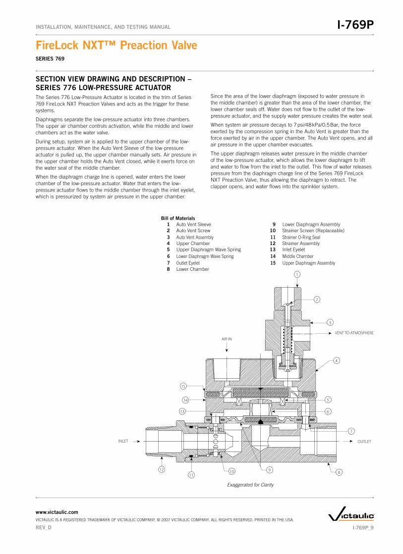
SECTION�VIEW�DRAWING�AND�DESCRIPTION�–�SERIES�776�LOW-PRESSURE�ACTUATORThe Series 776 Low-Pressure Actuator is located in the trim of Series 769 FireLock NXT Preaction Valves and acts as the trigger for these systems.
Diaphragms separate the low-pressure actuator into three chambers. The upper air chamber controls activation, while the middle and lower chambers act as the water valve.
During setup, system air is applied to the upper chamber of the low-pressure actuator. When the Auto Vent Sleeve of the low-pressure actuator is pulled up, the upper chamber manually sets. Air pressure in the upper chamber holds the Auto Vent closed, while it exerts force on the water seal of the middle chamber.
When the diaphragm charge line is opened, water enters the lower chamber of the low-pressure actuator. Water that enters the low- pressure actuator flows to the middle chamber through the inlet eyelet, which is pressurized by system air pressure in the upper chamber.
Since the area of the lower diaphragm (exposed to water pressure in the middle chamber) is greater than the area of the lower chamber, the lower chamber seals off. Water does not flow to the outlet of the low-pressure actuator, and the supply water pressure creates the water seal.
When system air pressure decays to 7 psi/48 kPa/0.5 Bar, the force exerted by the compression spring in the Auto Vent is greater than the force exerted by air in the upper chamber. The Auto Vent opens, and all air pressure in the upper chamber evacuates.
The upper diaphragm releases water pressure in the middle chamber of the low-pressure actuator, which allows the lower diaphragm to lift and water to flow from the inlet to the outlet. This flow of water releases pressure from the diaphragm charge line of the Series 769 FireLock NXT Preaction Valve, thus allowing the diaphragm to retract. The clapper opens, and water flows into the sprinkler system.
VENT TO ATMOSPHERE
INLET
AIR IN
OUTLET
1
2
3
4
5
6
7
891011
12
13
14
15
Exaggerated for Clarity
Bill�of�Materials� 1 Auto Vent Sleeve 9 Lower Diaphragm Assembly 2 Auto Vent Screw 10 Strainer Screen (Replaceable) 3 Auto Vent Assembly 11 Strainer O-Ring Seal 4 Upper Chamber 12 Strainer Assembly 5 Upper Diaphragm Wave Spring 13 Inlet Eyelet 6 Lower Diaphragm Wave Spring 14 Middle Chamber 7 Outlet Eyelet 15 Upper Diaphragm Assembly 8 Lower Chamber
REV_D
FireLock�NXT™�Preaction�ValveSERIES 769
I-769PINSTALLATION,�MAINTENANCE,�AND�TESTING�MANUAL
www.victaulic.comVICTAULIC IS A REGISTERED TRADEMARK OF VICTAULIC COMPANY. © 2007 VICTAULIC COMPANY. ALL RIGHTS RESERVED. PRINTED IN THE USA.
I-769P_9

SECTION�VIEW�DRAWING�AND�DESCRIPTION�–�SERIES�746-LPA�DRY�ACCELERATORThe Series 746-LPA Dry Accelerator is a quick-opening device, which exhausts air from the Series 776 Low-Pressure Actuator to speed valve operation.
A diaphragm separates the Series 746-LPA Dry Accelerator into two chambers. The closing chamber contains a compression spring, which maintains the chamber in the closed position. The closed position is maintained as long as the pressure differential between the opening and closing chambers is less than 3 psi/21 kPa/0.2 Bar.
When the system introduces air pressure into the dry accelerator, air enters the closing chamber and passes through a check valve to the opening chamber. The check valve, which allows flow into the open-ing chamber, prevents pressure from escaping the opening chamber. Therefore, air can escape only through the restrictor.
When a rapid loss of system air pressure occurs, such as an open sprinkler, air escapes from the closing chamber faster than it escapes from the opening chamber. As the sprinkler system’s pressure continues to decay, a differential pressure develops across the diaphragm. When this differential pressure reaches 3 – 5 psi/21 – 34 kPa/0.2 – 0.3 Bar, the opening chamber’s pressure overcomes the compression spring’s closing force, causing the closing chamber to open to the atmosphere. The closing chamber opens immediately and releases pressure from the actuator, resulting in valve operation.
NOTE: The Series 746-LPA Dry Accelerator must be used only on systems operating below 30 psi/206 kPa/2.1 Bar of air. If air pressure higher than 30 psi/206 kPa/2.1 Bar is required, the Series 746 Dry Accelerator should be used.
Exaggerated for Clarity
To PressureGauge
Air Inlet
CROSS-SECTION WITH UPPER CHAMBER ROTATED45° AND BOLT REMOVED FOR CLARITY
Bill of Materials 1 Opening/Air Chamber 9 O-Ring 2 Restrictor 10 Seal Support 3 Piston 11 Closing Chamber Seal 4 O-Ring 12 Button-Head Cap Screw 5 Diaphragm 13 Washer 6 Actuator Shaft 14 Adjustable Seat 7 Closing Chamber 15 Check Valve 8 Compression Spring
15
1
1413
1112
86
7
10
2
3
5
4
9
4
I-769P_10
FireLock�NXT™�Preaction�ValveSERIES 769
I-769PINSTALLATION,�MAINTENANCE,�AND�TESTING�MANUAL
www.victaulic.comVICTAULIC IS A REGISTERED TRADEMARK OF VICTAULIC COMPANY. © 2007 VICTAULIC COMPANY. ALL RIGHTS RESERVED. PRINTED IN THE USA.
REV_D

AIR�SUPPLY�REQUIREMENTSThe required air pressure for Series 769 FireLock NXT Preaction Valves is 13 psi/90 kPa/0.9 Bar minimum, regardless of the system supply water pressure. Normal air pressure should not exceed 18 psi/124 kPa/1.2 Bar. Failure to maintain air pressure within the 13 psi/90 kPa to 18 psi/ 124 kPa/1.2 Bar range may reduce system operation response time.
Systems with air pressure higher than 18 psi/124 kPa/1.2 Bar may require the addition of a Series 746-LPA Dry Accelerator. NOTE: The Series 746-LPA Dry Accelerator must be used only on systems oper-ating below 30 psi/206 kPa/2.1 Bar of air. If air pressure higher than 30 psi/206 kPa/2.1 Bar is required, the Series 746 Dry Accelerator should be used.
If multiple Series 769 FireLock NXT Preaction Valves are installed with a common air supply, isolate the systems with a spring-loaded, soft-seated ball check valve to ensure air integrity for each system. Good practice is to include a ball valve for isolation and service of each individual system.
Set the air pressure to the required system air pressure. Air pressure differing from the required system air pressure could reduce system operation response time.
The engineer/system designer is responsible for sizing the compressor so that the entire system is charged to the required air pressure within 30 minutes. DO NOT oversize the compressor to provide more airflow. An oversized compressor will slow down or possibly prevent valve operation.
If the compressor fills the system too fast, it may be necessary to restrict the air supply. Restricting the air supply will ensure that air being exhausted from an open sprinkler or manual release valve is not replaced by the air supply system as fast as it is being exhausted.
COMPRESSOR�SIZING
0
2
4
6
8
10
12
System Capacity (in gallons)
Requ
ired
Flo
w R
ate
(CFM
)
COMPRESSOR REQUIREMENTS
55
0
30
0
50
80
0
10
50
13
00
15
50
18
00
20 psi/138 kPa13 psi/90 kPa
BASE�OR�RISER-MOUNTED�AIR�COMPRESSORS
For base or riser-mounted air compressors, the recommended air pressure of 13 psi/90 kPa/0.9 Bar is the “on” or “low” pressure set-ting for the compressor. The “off” or “high” pressure setting should be 18 psi/124 kPa/1.2 Bar.
When a base or riser-mounted air compressor supplies air to a Series 769 FireLock NXT Preaction Valve, it is not necessary to install the Victaulic Series 757 Regulated Air Maintenance Trim Assembly (AMTA). In this case, the air line of the compressor connects to the trim at the fitting where the Series 757 Regulated AMTA is normally installed (refer to the applicable trim drawing). If the compressor is not equipped with a pressure switch, the Series 757P Air Maintenance Trim Assembly with Pressure Switch should be installed.
SHOP�AIR�OR�TANK-MOUNTED�AIR�COMPRESSORS
In the event a compressor becomes inoperative, a properly sized tank-mounted air compressor provides the greatest protection for systems.
When shop air or a tank-mounted air compressor is used, the Series 757 Regulated AMTA must be installed. The Series 757 Regulated AMTA provides proper air regulation from the air reservoir to the sprinkler system.
For tank-mounted air compressors, the recommended air pressure of 13 psi/90 kPa/0.9 Bar should be used as the set point for the air regulator. The “on” pressure of the compressor should be at least 5 psi/34 kPa/0.3 Bar above the set point of the air regulator.
VICTAULIC�SERIES�757�REGULATED�AIR�MAINTENANCE�TRIM�ASSEMBLY�(AMTA)�OPTION
NOTICE
Victaulic�recommends�a�maximum�of�two�Series�769�FireLock�•�NXT�Preaction�Valves�per�Series�757�Regulated�AMTA.
16
54
2
3
Bill of Materials 1 1⁄8"/3.2 mm Restrictor 2 Slow Fill Ball Valve (Normally Open) 3 Air Regulator 4 Strainer (100 Mesh) 5 Spring-Loaded, Soft-Seated Ball Check Valve 6 Fast Fill Ball Valve (Normally Closed)
REV_D
FireLock�NXT™�Preaction�ValveSERIES 769
I-769PINSTALLATION,�MAINTENANCE,�AND�TESTING�MANUAL
www.victaulic.comVICTAULIC IS A REGISTERED TRADEMARK OF VICTAULIC COMPANY. © 2007 VICTAULIC COMPANY. ALL RIGHTS RESERVED. PRINTED IN THE USA.
I-769P_11

VICTAULIC�SERIES�757P�AIR�MAINTENANCE�TRIM�ASSEMBLY�(AMTA)�WITH�PRESSURE�SWITCH�OPTION
NOTICE
Victaulic�recommends�a�maximum�of�two�Series�769�FireLock�•�NXT�Preaction�Valves�per�Series�757P�AMTA�with�Pressure�Switch.
Refer�to�the�I-757P�Air�Maintenance�Trim�Assembly�with�•�Pressure�Switch�Installation�Instructions,�supplied�with�the�product,�for�complete�installation,�electrical,�and�pressure�switch�adjustment�information.
5
2
12
7
8
15
10
16
9
6
4
1
13
3
14
11
TOSYSTEM
FROM COMPRESSOR
Bill of MaterialsItem Qty. Description 1 1 Restrictor (½-inch NPT) 2 1 Strainer (½-inch NPT) 3 1 Swing Check (½-inch NPT) 4 1 Slow-Fill Ball Valve (Normally Open) 5 1 Spring-Loaded, Soft-Seated Check Valve 6 1 Pressure Switch 7 2 Compression Fitting, Straight (¼-inch NPT x ¼-inch Tube) 8 1 Copper Tubing (¼-inch OD) 9 11 Close Nipple (½-inch NPT x 1.13) 10 1 Nipple (½-inch NPT x 4.00) 11 1 90° Female Elbow (½-inch NPT) 12 4 Female Tee (½-inch NPT) 13 3 Union (½-inch NPT) 14 2 Reducing Bushing (½-inch NPT x ¼-inch NPT) 15 1 Fast-Fill Ball Valve (Normally Closed) 16 1 Pressure Switch Isolation Ball Valve (Normally Open - Lockable)
COMPRESSOR�REQUIREMENTS�AND�SETTINGS�FOR�SERIES�769�FIRELOCK�NXT�PREACTION�VALVES�INSTALLED�WITH�SERIES�746-LPA�DRY�ACCELERATORS
Set the air regulator of the Series 757 Regulated AMTA to a minimum of 13 psi/90 kPa/0.9 Bar.
The�Series�757P�Air�Maintenance�Trim�Assembly�with�Pressure�Switch�MUST�NOT�be�used�on�a�Series�769�FireLock�NXT�Preaction�Valve�installed�with�a�Series�746-LPA�Dry�Accelerator,�unless�a�tank�and�air�regulator�are�added.
In the event a compressor becomes inoperative, a properly sized tank-mounted air compressor provides the greatest protection for systems installed with a Series 746-LPA Dry Accelerator. In this situation, air can be supplied continuously to the sprinkler system for an extended time period. NOTE: The Series 757 Regulated AMTA should be used with a tank-mounted air compressor to supply air to a Series 769 FireLock NXT Preaction Valve when the Series 746-LPA Dry Accelerator is used. The use of an air regulator with a base or riser-mounted air compressor could cause short cycling, resulting in premature wear of the compressor.
The air regulator of the Series 757 Regulated AMTA is a relief-type design. Any pressure in the system that is above the set point of the air regulator will be released. Therefore, charging the air regulator above the set point could cause premature operation of a valve installed with a Series 746-LPA Dry Accelerator.
SETTINGS�FOR�AIR�SUPERVISORY�PRESSURE�SWITCHES�AND�ALARM�PRESSURE�SWITCHES
Air supervisory pressure switches are required for preaction 1. systems and must be set according to the following notes. NOTE: Switches for Vic-Quick Risers are pre-set at the factory.
1a. Wire the air supervisory pressure switches to activate a low-pressure alarm signal. NOTE: In addition, the local authority having jurisdiction may require a high-pressure alarm. Contact the local authority having jurisdiction for this requirement.
1b. Set the air supervisory pressure switches to activate at 2 – 4 psi/14 – 28 kPa/0.1 – 0.3 Bar below the minimum air pressure required (but not lower than 10 psi/69 kPa/0.7 Bar).
1c. Wire the alarm pressure switch to activate a water flow alarm.
1d. Set the alarm pressure switch to activate on a pressure rise of 4 – 8 psi/28 – 55 kPa/0.3 – 0.6 Bar.
REMOTE�SYSTEM�TEST�VALVE�REQUIREMENTS
The remote system test valve (inspector’s test connection) should contain a UL Listed and/or FM Approved valve (normally closed), which can be opened to simulate the operation of a sprinkler.
The remote system test valve (inspector’s test connection) should be located at the most hydraulically demanding location in the release system. NOTE: Multiple restrictions on the remote system test valve (inspector’s test connection) may slow the air decay rate and cause the system to respond slower than required.
The remote system test valve (inspector’s test connection) should termi-nate with an orifice equal to the smallest orifice in the releasing system.
The remote system test valve (inspector’s test connection) is used to ensure that water reaches the most remote part of the system within 60 seconds.
I-769P_12
FireLock�NXT™�Preaction�ValveSERIES 769
I-769PINSTALLATION,�MAINTENANCE,�AND�TESTING�MANUAL
www.victaulic.comVICTAULIC IS A REGISTERED TRADEMARK OF VICTAULIC COMPANY. © 2007 VICTAULIC COMPANY. ALL RIGHTS RESERVED. PRINTED IN THE USA.
REV_D
IMPORTANT�INSTALLATION�INFORMATION1. For proper operation and approval, the Series 769 FireLock NXT
Preaction Valve must be installed in accordance with the specific trim diagrams included with the shipment. NOTE: Victaulic pro-vides specific trim diagrams for installations involving a Series 746-LPA Dry Accelerator.
2. Before installing the Series 769 FireLock NXT Preaction Valve, flush the water supply piping thoroughly to remove all foreign material.
3. Series 769 FireLock NXT Preaction Valves MUST NOT be located in an area where the valve can be exposed to freezing tempera-tures. In addition, the Series 769 FireLock NXT Preaction Valve MUST NOT be located in an area where physical damage may occur.
4. It is the system designer’s responsibility to confirm material com-patibility of the Series 769 FireLock NXT Preaction Valve, trim, and associated accessories when a corrosive environment or contami-nated water is present.
5. SERIES�769�FIRELOCK�NXT�PREACTION�VALVES�MUST�BE�INSTALLED�ONLY�IN�THE�VERTICAL�POSITION�WITH�THE�ARROW�ON�THE�BODY�POINTING�UPWARD.
6. Air or nitrogen supply to the dry piping system must be clean, dry, and oil-free.
7. Air supplies must be regulated, restricted, and continuous.
8. When an uninterruptible water flow alarm is required, Victaulic recommends the use of a low-pressure alarm installed on the diaphragm charge line downstream of the strainer/check restric-tor. Another option is to install a Series 75B Supplemental Alarm Device.
9. Per NFPA 13 requirements, piping must be pitched so that systems can drain properly. For areas that are subject to high levels of condensation, or where piping is not properly pitched, an optional Series 75D Water Column Device kit is available to assist in automatically draining water out of the riser.
VALVE/TRIM�INSTALLATION1. Make sure the trim drawing matches the system’s requirements.
CAUTION
Make�sure�the�foam�spacer�is�removed�from�•�inside�the�valve�body�before�attempting�to�install�the�valve.
Failure�to�follow�this�instruction�could�cause�improper�valve�operation,�resulting�in�personal�injury�and/or�property�damage.
2. Remove all plastic caps and foam spacers from the valve.
3. Apply a small amount of pipe joint compound or Teflon* tape to the external threads of all threaded pipe connections. DO NOT get any tape, compound, or other foreign material into the valve body, pipe nipples, or valve openings.
CAUTIONMake�sure�no�foreign�material�gets�into�the�valve�body,�pipe�•�nipples,�or�valve�openings.
If�using�any�material�other�than�Teflon�tape,�use�extra�caution�•�so�that�no�material�gets�into�the�trim.
Failure�to�follow�these�instructions�could�cause�improper�valve�operation,�resulting�in�personal�injury�and/or�property�damage.
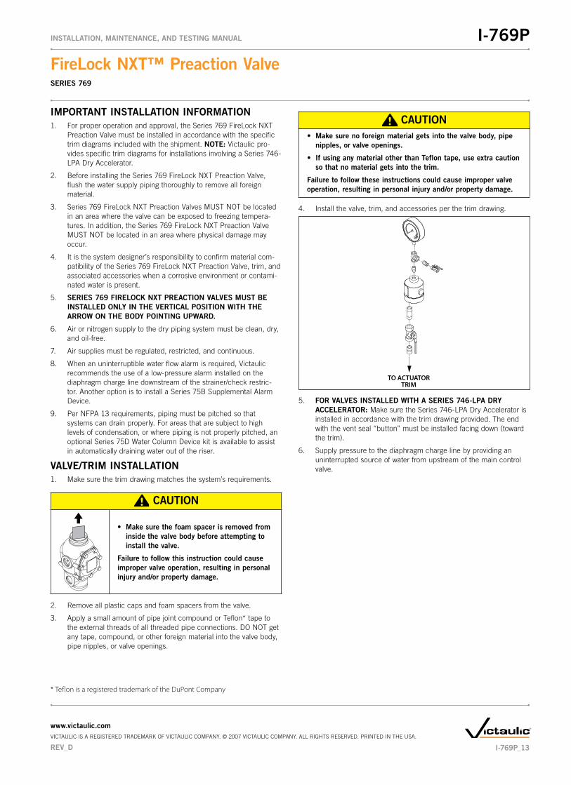
4. Install the valve, trim, and accessories per the trim drawing.
TO ACTUATORTRIM
5. FOR�VALVES�INSTALLED�WITH�A�SERIES�746-LPA�DRY�ACCELERATOR:�Make sure the Series 746-LPA Dry Accelerator is installed in accordance with the trim drawing provided. The end with the vent seal “button” must be installed facing down (toward the trim).
6. Supply pressure to the diaphragm charge line by providing an uninterrupted source of water from upstream of the main control valve.
* Teflon is a registered trademark of the DuPont Company
REV_D
FireLock�NXT™�Preaction�ValveSERIES 769
I-769PINSTALLATION,�MAINTENANCE,�AND�TESTING�MANUAL
www.victaulic.comVICTAULIC IS A REGISTERED TRADEMARK OF VICTAULIC COMPANY. © 2007 VICTAULIC COMPANY. ALL RIGHTS RESERVED. PRINTED IN THE USA.
I-769P_13

COMPRESSION�FITTING�AND�TUBE�INSTALLATION
Compression Fitting and Tube Configuration for Auto Drain and Drip Check
Compression Fitting and Tube Configuration for Actuator
Compression fittings and tubes are provided for connection from the outlet of the auto drain, drip check, and actuator to the drip cup or drain. These compression fittings and tubes must be installed, in accor-dance with the trim drawing provided. NEVER insert a plug into the out-let of the auto drain, drip check, or actuator in place of the compression fitting/tube.
HYDROSTATIC TESTING
WARNING
If�air�testing�is�required,�DO�NOT�exceed�•�50�psi/345�kPa/3.4�Bar�air�pressure.
Failure�to�follow�this�instruction�could�result�in�serious�personal�injury�and/or�property��damage.
The Victaulic Series 769 FireLock NXT Preaction Valve is UL Listed and FM Approved for a maximum working pressure of 300 psi/2065 kPa/ 20.7 Bar and is factory tested to 600 psi/4135 kPa/41.4 Bar for all sizes. The valve can be hydrostatically tested against the clapper at 200 psi/1380 kPa/13.8 Bar or 50 psi/345 kPa/3.4 Bar above the normal water supply pressure (2-hour limited time period) for acceptance by the authority having jurisdiction.
I-769P_14
FireLock�NXT™�Preaction�ValveSERIES 769
I-769PINSTALLATION,�MAINTENANCE,�AND�TESTING�MANUAL
www.victaulic.comVICTAULIC IS A REGISTERED TRADEMARK OF VICTAULIC COMPANY. © 2007 VICTAULIC COMPANY. ALL RIGHTS RESERVED. PRINTED IN THE USA.
REV_D
PLACING�THE�SYSTEM�IN�SERVICE•� NON-INTERLOCKED,�PNEUMATIC�RELEASE
•� NON-INTERLOCKED�PNEUMATIC/ELECTRIC�RELEASE
•� SINGLE-INTERLOCKED,�PNEUMATIC�RELEASE
•� SINGLE-INTERLOCKED,�ELECTRIC�RELEASE
•� DOUBLE-INTERLOCKED,�ELECTRIC�(ELECTRIC-PNEUMATIC/ � ELECTRIC)�RELEASE
CAUTIONMake�sure�the�Series�769�FireLock�NXT�Preaction�Valve�is�•�properly�heated�and�protected�from�freezing�temperatures�and�physical�damage.
Failure�to�follow�this�instruction�could�cause�improper�valve�operation,�resulting�in�personal�injury�and/or�property�damage.
NOTICE
A�non-interlocked,�pneumatic�release�system�is�shown�in�the�•�photos�below.
1. Open the system main drain valve. Confirm that the system is drained.
2. Close the system main drain valve.
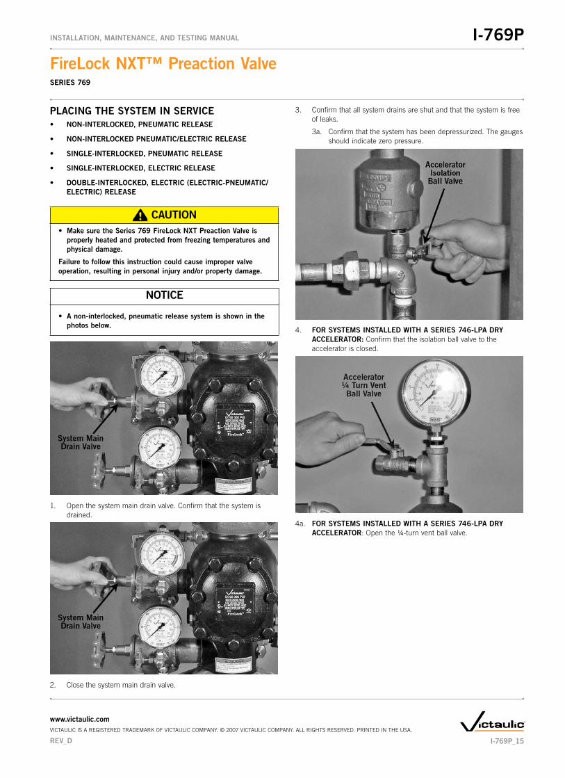
3. Confirm that all system drains are shut and that the system is free of leaks.
3a. Confirm that the system has been depressurized. The gauges should indicate zero pressure.
4. FOR�SYSTEMS�INSTALLED�WITH�A�SERIES�746-LPA�DRY�ACCELERATOR: Confirm that the isolation ball valve to the accelerator is closed.
4a. FOR�SYSTEMS�INSTALLED�WITH�A�SERIES�746-LPA�DRY�ACCELERATOR: Open the 1/4-turn vent ball valve.
REV_D
FireLock�NXT™�Preaction�ValveSERIES 769
I-769PINSTALLATION,�MAINTENANCE,�AND�TESTING�MANUAL
www.victaulic.comVICTAULIC IS A REGISTERED TRADEMARK OF VICTAULIC COMPANY. © 2007 VICTAULIC COMPANY. ALL RIGHTS RESERVED. PRINTED IN THE USA.
I-769P_15
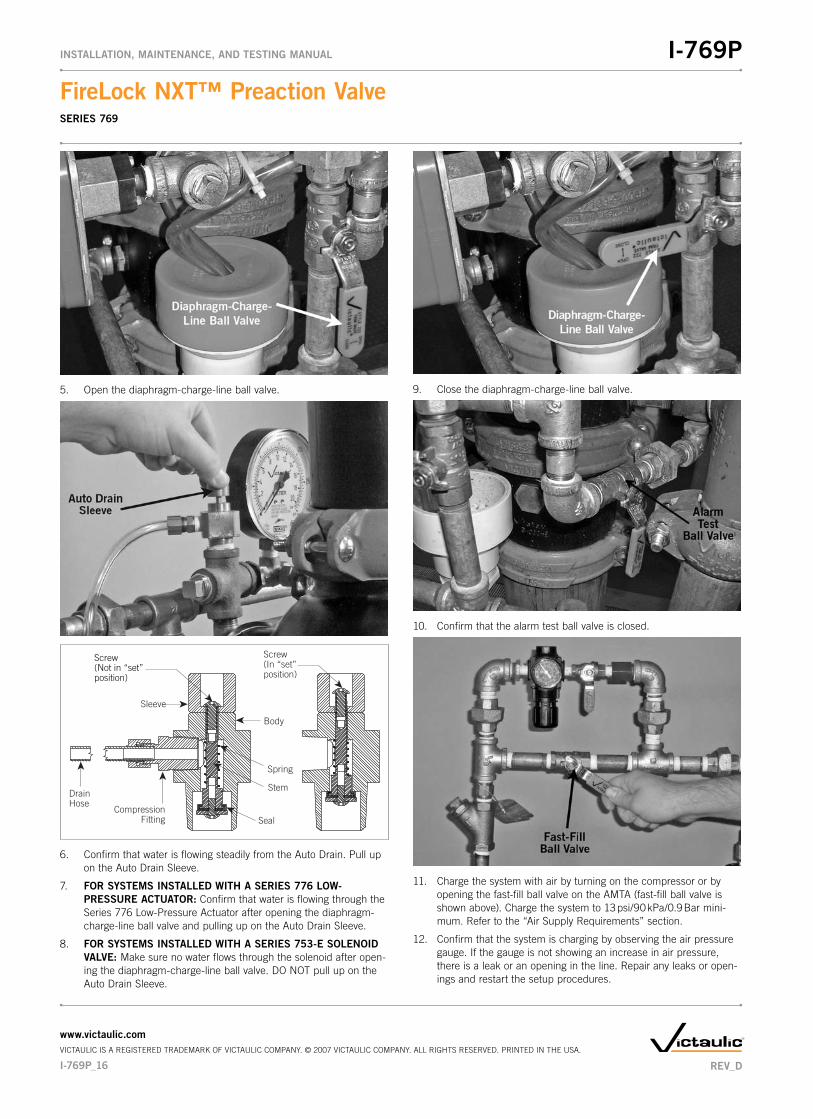
5. Open the diaphragm-charge-line ball valve.
Screw(Not in “set”position)
SealCompression
Fitting
DrainHose
Body
Spring
Stem
Screw(In “set”position)
Sleeve
6. Confirm that water is flowing steadily from the Auto Drain. Pull up on the Auto Drain Sleeve.
7. FOR�SYSTEMS�INSTALLED�WITH�A�SERIES�776�LOW-PRESSURE�ACTUATOR: Confirm that water is flowing through the Series 776 Low-Pressure Actuator after opening the diaphragm-charge-line ball valve and pulling up on the Auto Drain Sleeve.
8. FOR�SYSTEMS�INSTALLED�WITH�A�SERIES�753-E�SOLENOID�VALVE:�Make sure no water flows through the solenoid after open-ing the diaphragm-charge-line ball valve. DO NOT pull up on the Auto Drain Sleeve.
9. Close the diaphragm-charge-line ball valve.
10. Confirm that the alarm test ball valve is closed.
11. Charge the system with air by turning on the compressor or by opening the fast-fill ball valve on the AMTA (fast-fill ball valve is shown above). Charge the system to 13 psi/90 kPa/0.9 Bar mini-mum. Refer to the “Air Supply Requirements” section.
12. Confirm that the system is charging by observing the air pressure gauge. If the gauge is not showing an increase in air pressure, there is a leak or an opening in the line. Repair any leaks or open-ings and restart the setup procedures.
I-769P_16
FireLock�NXT™�Preaction�ValveSERIES 769
I-769PINSTALLATION,�MAINTENANCE,�AND�TESTING�MANUAL
www.victaulic.comVICTAULIC IS A REGISTERED TRADEMARK OF VICTAULIC COMPANY. © 2007 VICTAULIC COMPANY. ALL RIGHTS RESERVED. PRINTED IN THE USA.
REV_D

13. FOR�SYSTEMS�INSTALLED�WITH�A�SERIES�776�LOW-PRESSURE�ACTUATOR: Confirm that no water is being exhausted from the Auto Vent of the Series 776 Low-Pressure Actuator. If water is being exhausted from the Auto Vent, continue to run air through the system in order to remove moisture from the upper chamber of the Series 776 Low-Pressure Actuator. If a Series 746-LPA Dry Accelerator is installed, make sure the accelerator is not flooded.
14. FOR�SYSTEMS�INSTALLED�WITH�A�SERIES�776�LOW-PRESSURE�ACTUATOR: When the system reaches approximately 10 psi/69 kPa/0.7 Bar, and no additional moisture is being released from the Auto Vent, pull up on the Auto Vent Sleeve of the Series 776 Low-Pressure Actuator. NOTE: The Auto Vent Screw should seal and remain in the set (“UP”) position.
15. FOR�SYSTEMS�INSTALLED�WITH�A�SERIES�753-E�SOLENOID�VALVE: Confirm that the solenoid is closed.
16. When system air pressure is established, close the fast-fill ball valve on the AMTA.
17. Open the slow-fill ball valve on the AMTA. NOTE: Failure to leave the slow-fill ball valve open may allow system pressure to drop, resulting in valve operation in the event of a system leak.
18. Open the diaphragm-charge-line ball valve. Allow water to flow through the Auto Drain tube.
19. Open the manual pull station.
REV_D
FireLock�NXT™�Preaction�ValveSERIES 769
I-769PINSTALLATION,�MAINTENANCE,�AND�TESTING�MANUAL
www.victaulic.comVICTAULIC IS A REGISTERED TRADEMARK OF VICTAULIC COMPANY. © 2007 VICTAULIC COMPANY. ALL RIGHTS RESERVED. PRINTED IN THE USA.
I-769P_17

20. Close the manual pull station.
21. Pull up on the Auto Drain Sleeve until the screw is in the set (“UP”) position. Verify that there is pressure on the gauge to the diaphragm charge line.
22. When the diaphragm charge line is pressurized, temporarily close the diaphragm-charge-line ball valve. Confirm that the diaphragm charge line is maintaining pressure by observing the diaphragm-charge-line pressure gauge.
22a. If pressure in the diaphragm charge line drops, the diaphragm must be replaced and/or any leaks in the diaphragm charge line must be corrected. Refer to the “Removing and Replacing the Diaphragm Assembly” section.
22b. If pressure in the diaphragm charge line does not drop, re-open the diaphragm-charge-line ball valve, and proceed to the following step.
23. FOR�SYSTEMS�INSTALLED�WITH�A�SERIES��746-LPA�DRY�ACCELERATOR: Close the 1/4-turn vent ball valve on the accelerator.
I-769P_18
FireLock�NXT™�Preaction�ValveSERIES 769
I-769PINSTALLATION,�MAINTENANCE,�AND�TESTING�MANUAL
www.victaulic.comVICTAULIC IS A REGISTERED TRADEMARK OF VICTAULIC COMPANY. © 2007 VICTAULIC COMPANY. ALL RIGHTS RESERVED. PRINTED IN THE USA.
REV_D

24. FOR�SYSTEMS�INSTALLED�WITH�A�SERIES�746-LPA�DRY�ACCELERATOR: Open the isolation ball valve. This will set the accelerator
25. Observe the system air pressure over a 24-hour period to confirm system integrity. If there is degradation in system air pressure, find and correct all leaks. NOTE: NFPA requires less than 11/2-psi/ 14-kPa/0.1-Bar leakage in 24 hours.
26. Open the water supply main drain valve.
CAUTIONTake�precautions�when�opening�the�water�supply�main�control�•�valve,�since�water�will�flow�from�all�open�system�valves.
Failure�to�follow�this�instruction�could�result�in�property�damage.
Water Supply Main Control Valve
27. Open the water supply main control valve slowly until water flows steadily from the open water supply main drain valve.
28. Close the water supply main drain valve when a steady flow of water occurs.
29. Confirm that there is no leakage from the intermediate valve chamber. The drip check in the alarm line should not be leaking water or air.
REV_D
FireLock�NXT™�Preaction�ValveSERIES 769
I-769PINSTALLATION,�MAINTENANCE,�AND�TESTING�MANUAL
www.victaulic.comVICTAULIC IS A REGISTERED TRADEMARK OF VICTAULIC COMPANY. © 2007 VICTAULIC COMPANY. ALL RIGHTS RESERVED. PRINTED IN THE USA.
I-769P_19
Water Supply Main Control Valve
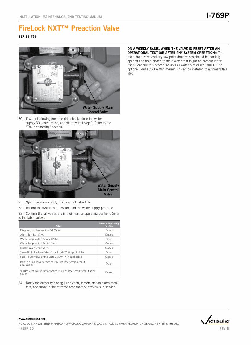
30. If water is flowing from the drip check, close the water supply 30 control valve, and start over at step 1. Refer to the “Troubleshooting” section.
Water Supply Main Control
Valve
31. Open the water supply main control valve fully.
32. Record the system air pressure and the water supply pressure.
33. Confirm that all valves are in their normal operating positions (refer to the table below).
ValveNormal�Operating�
Position
Diaphragm-Charge-Line Ball Valve Open
Alarm Test Ball Valve Closed
Water Supply Main Control Valve Open
Water Supply Main Drain Valve Closed
System Main Drain Valve Closed
Slow-Fill Ball Valve of the Victaulic AMTA (if applicable) Open
Fast-Fill Ball Valve of the Victaulic AMTA (if applicable) Closed
Isolation Ball Valve for Series 746-LPA Dry Accelerator (if applicable) Open
1/4-Turn Vent Ball Valve for Series 746-LPA Dry Accelerator (if appli-cable) Closed
34. Notify the authority having jurisdiction, remote station alarm moni-tors, and those in the affected area that the system is in service.
ON�A�WEEKLY�BASIS,�WHEN�THE�VALVE�IS�RESET�AFTER�AN�OPERATIONAL�TEST�(OR�AFTER�ANY�SYSTEM�OPERATION): The main drain valve and any low-point drain valves should be partially opened and then closed to drain water that might be present in the riser. Continue this procedure until all water is released. NOTE:�The optional Series 75D Water Column Kit can be installed to automate this step.
I-769P_20
FireLock�NXT™�Preaction�ValveSERIES 769
I-769PINSTALLATION,�MAINTENANCE,�AND�TESTING�MANUAL
www.victaulic.comVICTAULIC IS A REGISTERED TRADEMARK OF VICTAULIC COMPANY. © 2007 VICTAULIC COMPANY. ALL RIGHTS RESERVED. PRINTED IN THE USA.
REV_D
EXTERNAL�INSPECTION
WARNING�The�building�owner�or�their�representative�is�responsible�for�•�maintaining�the�fire�protection�system�in�proper�operating��condition.
To�ensure�proper�system�operation,�valves�must�be�inspected�•�in�accordance�with�current�NFPA-25�requirements�or�in�accor-dance�with�the�requirements��of�the�local�authority�having�jurisdiction�(whichever�is�more�stringent).�Always�refer�to�the�instructions�in�this�manual�for�additional�inspection�and�testing�requirements.
The�frequency�of�inspections�must�be�increased�in�the�pres-•�ence�of�contaminated�water�supplies,�corrosive/scaling�water�supplies,�and�corrosive�atmospheres.
Depressurize�and�drain�the�piping�system�before�attempting�to�•�install,�remove,�adjust,�or�maintain�any�Victaulic�products.
Failure�to�follow�these�instructions�could�cause�system�failure,�resulting�in�death,�serious�personal�injury,�and�property�damage.
NOTICEAny�activities�that�require�taking�the�valve�out�of�service�may�•�eliminate�the�fire�protection�provided.
Consideration�of�a�fire�patrol�should�be�given�for�the�affected�•�areas.
Before�servicing�or�testing�the�system,�notify�the�authority�•��having�jurisdiction.
WEEKLY�INSPECTION
1. Perform a visual inspection on the valve and trim on a weekly basis. NOTE: If the preaction system is equipped with a low- pressure alarm, monthly inspections may be sufficient. Contact the local authority having jurisdiction for specific requirements.
MONTHLY�INSPECTION
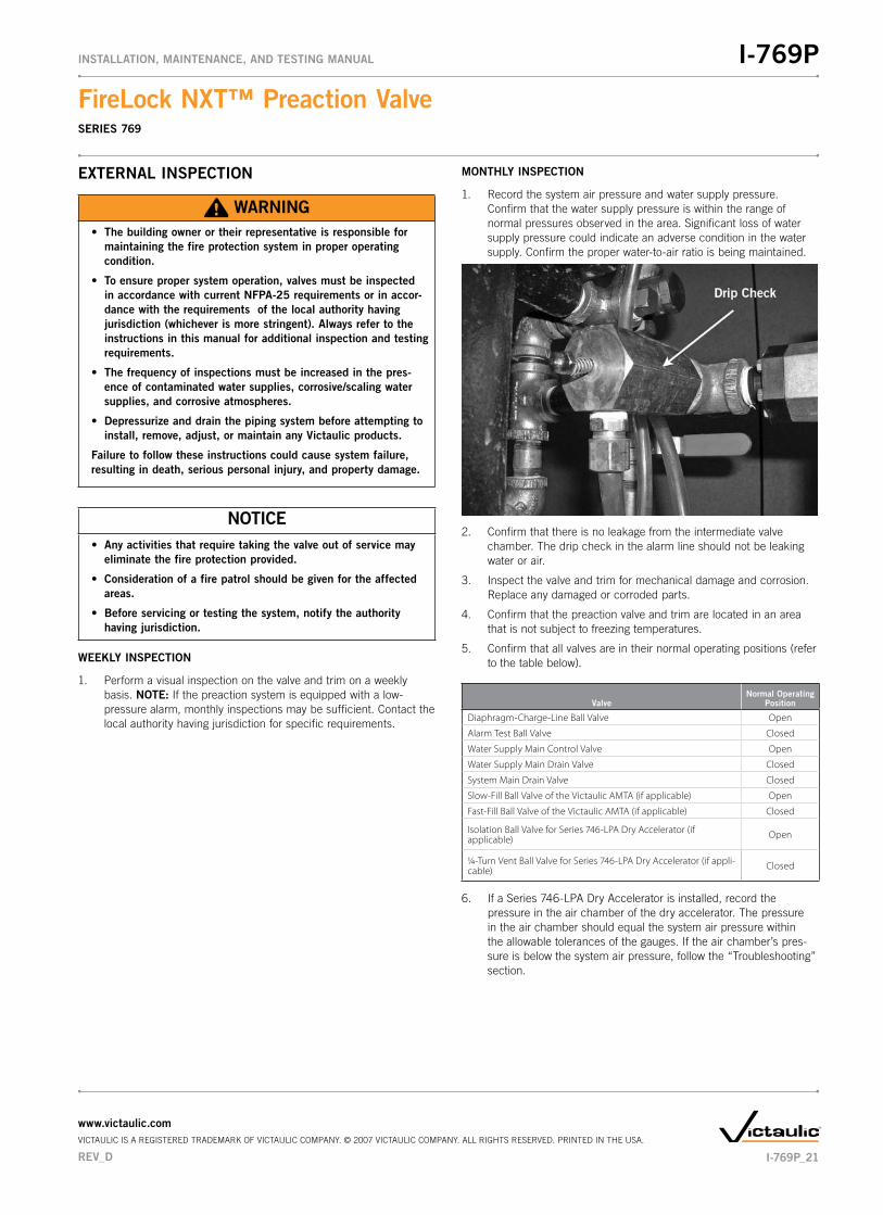
1. Record the system air pressure and water supply pressure. Confirm that the water supply pressure is within the range of normal pressures observed in the area. Significant loss of water supply pressure could indicate an adverse condition in the water supply. Confirm the proper water-to-air ratio is being maintained.
2. Confirm that there is no leakage from the intermediate valve chamber. The drip check in the alarm line should not be leaking water or air.
3. Inspect the valve and trim for mechanical damage and corrosion. Replace any damaged or corroded parts.
4. Confirm that the preaction valve and trim are located in an area that is not subject to freezing temperatures.
5. Confirm that all valves are in their normal operating positions (refer to the table below).
ValveNormal�Operating�
Position
Diaphragm-Charge-Line Ball Valve Open
Alarm Test Ball Valve Closed
Water Supply Main Control Valve Open
Water Supply Main Drain Valve Closed
System Main Drain Valve Closed
Slow-Fill Ball Valve of the Victaulic AMTA (if applicable) Open
Fast-Fill Ball Valve of the Victaulic AMTA (if applicable) Closed
Isolation Ball Valve for Series 746-LPA Dry Accelerator (if applicable) Open
1/4-Turn Vent Ball Valve for Series 746-LPA Dry Accelerator (if appli-cable) Closed
6. If a Series 746-LPA Dry Accelerator is installed, record the pressure in the air chamber of the dry accelerator. The pressure in the air chamber should equal the system air pressure within the allowable tolerances of the gauges. If the air chamber’s pres-sure is below the system air pressure, follow the “Troubleshooting” section.
REV_D
FireLock�NXT™�Preaction�ValveSERIES 769
I-769PINSTALLATION,�MAINTENANCE,�AND�TESTING�MANUAL
www.victaulic.comVICTAULIC IS A REGISTERED TRADEMARK OF VICTAULIC COMPANY. © 2007 VICTAULIC COMPANY. ALL RIGHTS RESERVED. PRINTED IN THE USA.
I-769P_21
REQUIRED�TESTS
WARNING�The�building�owner�or�their�representative�is�responsible�for�•�maintaining�the�fire�protection�system�in�proper�operating��condition.
To�ensure�proper�system�operation,�valves�must�be�inspected�•�in�accordance�with�current�NFPA-25�requirements�or�in�accor-dance�with�the�requirements�of�the�local�authority�having�jurisdiction�(whichever�is�more�stringent).�Always�refer�to�the�instructions�in�this�manual�for�additional�inspection�and�testing�requirements.
The�frequency�of�inspections�must�be�increased�in�the�pres-•�ence�of�contaminated�water�supplies,�corrosive/scaling�water�supplies,�and�corrosive�atmospheres.
Depressurize�and�drain�the�piping�system�before�attempting�to�•�install,�remove,�adjust,�or�maintain�any�Victaulic�products.
Failure�to�follow�these�instructions�could�cause�system�failure,�resulting�in�death,�serious�personal�injury,�and�property�damage.
NOTICEAny�activities�that�require�taking�the�valve�out�of�service�may�•�eliminate�the�fire�protection�provided.
Consideration�of�a�fire�patrol�should�be�given�for�the�affected�•�areas.
Before�servicing�or�testing�the�system,�notify�the�authority�•��having�jurisdiction.
MAIN�DRAIN�TEST
Perform the main drain test on a frequency required by the current NFPA-25 code. The authority having jurisdiction in the area may require these tests on a more frequent basis. Verify these requirements by contacting the authority having jurisdiction in the affected area.
1. Notify the authority having jurisdiction, remote station alarm monitors, and those in the affected area that the main drain test will be performed.
2. Confirm that sufficient drainage is available.
3. Record the water supply pressure and system air pressure.
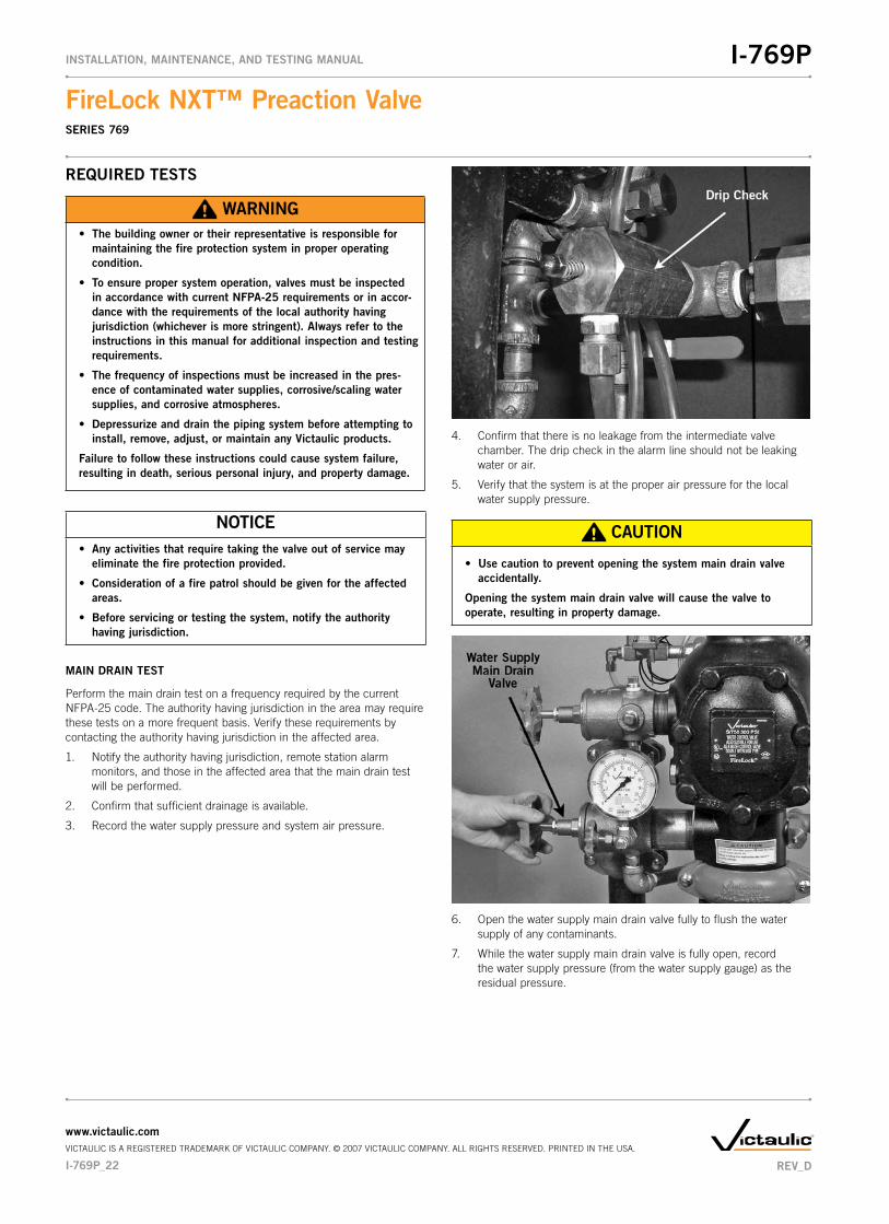
4. Confirm that there is no leakage from the intermediate valve chamber. The drip check in the alarm line should not be leaking water or air.
5. Verify that the system is at the proper air pressure for the local water supply pressure.
CAUTION
Use�caution�to�prevent�opening�the�system�main�drain�valve�•�accidentally.
Opening�the�system�main�drain�valve�will�cause�the�valve�to�operate,�resulting�in�property�damage.
6. Open the water supply main drain valve fully to flush the water supply of any contaminants.
7. While the water supply main drain valve is fully open, record the water supply pressure (from the water supply gauge) as the r esidual pressure.
I-769P_22
FireLock�NXT™�Preaction�ValveSERIES 769
I-769PINSTALLATION,�MAINTENANCE,�AND�TESTING�MANUAL
www.victaulic.comVICTAULIC IS A REGISTERED TRADEMARK OF VICTAULIC COMPANY. © 2007 VICTAULIC COMPANY. ALL RIGHTS RESERVED. PRINTED IN THE USA.
REV_D

8. Close the water supply main drain valve slowly.
9. Record the water pressure established after closing the water supply main drain valve.
10. Compare the residual pressure reading, taken above, to the residual pressure readings taken in previous main drain tests. If there is degradation in the residual water supply reading, restore the proper water supply pressure.
11. Confirm that all valves are in their normal operating positions (refer to the table below).
ValveNormal�Operating�
Position
Diaphragm-Charge-Line Ball Valve Open
Alarm Test Ball Valve Closed
Water Supply Main Control Valve Open
Water Supply Main Drain Valve Closed
System Main Drain Valve Closed
Slow-Fill Ball Valve of the Victaulic AMTA (if applicable) Open
Fast-Fill Ball Valve of the Victaulic AMTA (if applicable) Closed
Isolation Ball Valve for Series 746-LPA Dry Accelerator (if applicable) Open
1/4-Turn Vent Ball Valve for Series 746-LPA Dry Accelerator (if appli-cable) Closed
12. Confirm that there is no leakage from the intermediate valve chamber. The drip check in the alarm line should not be leaking water or air.
13. Notify the authority having jurisdiction, remote station alarm monitors, and those in the affected area that the valve is back in service.
14. Provide test results to the authority having jurisdiction, if required.
REV_D
FireLock�NXT™�Preaction�ValveSERIES 769
I-769PINSTALLATION,�MAINTENANCE,�AND�TESTING�MANUAL
www.victaulic.comVICTAULIC IS A REGISTERED TRADEMARK OF VICTAULIC COMPANY. © 2007 VICTAULIC COMPANY. ALL RIGHTS RESERVED. PRINTED IN THE USA.
I-769P_23

WATER�FLOW�ALARM�TEST
Perform the water flow alarm test on a frequency required by the current NFPA-25 code. The authority having jurisdiction in the area may require these tests on a more frequent basis. Verify these requirements by contacting the authority having jurisdiction in the affected area.
1. Notify the authority having jurisdiction, remote station alarm monitors, and those in the affected area that the water flow alarm test will be performed.
CAUTION
Use�caution�to�prevent�opening�the�system�main�drain�valve�•�accidentally.
Opening�the�system�main�drain�valve�will�cause�the�valve�to�operate,�resulting�in�property�damage.
2. Open the water supply main drain valve fully to flush the water supply of any contaminants.
3. Close the water supply main drain valve.
4. Open the alarm test ball valve. Confirm that mechanical and elec-trical alarms are activated and that remote monitoring stations, if provided, receive an alarm signal.
5. Close the alarm test ball valve after verifying proper operation of all alarms.
6. Push in the plunger of the drip check to verify that there is no pressure in the alarm line.
I-769P_24
FireLock�NXT™�Preaction�ValveSERIES 769
I-769PINSTALLATION,�MAINTENANCE,�AND�TESTING�MANUAL
www.victaulic.comVICTAULIC IS A REGISTERED TRADEMARK OF VICTAULIC COMPANY. © 2007 VICTAULIC COMPANY. ALL RIGHTS RESERVED. PRINTED IN THE USA.
REV_D

7. Verify that all alarms stopped sounding, that the alarm line drained properly, and that remote station alarms reset properly.
8. Confirm that there is no leakage from the intermediate valve chamber. The drip check in the alarm line should not be leaking water or air.
9. Notify the authority having jurisdiction, remote station alarm monitors, and those in the affected area that the valve is back in service.
10. Provide test results to the authority having jurisdiction, if required.
WATER�LEVEL�AND�LOW�AIR�ALARM�TESTS
Perform the water level and low air alarm tests on a frequency required by the current NFPA-25 code. The authority having jurisdiction in the area may require these tests on a more frequent basis. Verify these requirements by contacting the authority having jurisdiction in the affected area.
NOTICEIf�a�Series��746-LPA�Dry�Accelerator�is�installed,�make�sure�the�•�authority�having�jurisdiction�is�notified�that�the�water�level�and�low�air�alarm�tests�are�in�progress.�Failure�to�close�the�isolation�ball�valve�of�the�Series�746-LPA�Dry�Accelerator�may�cause�the�valve�to�trip,�resulting�in�a�false�alarm.
1. Notify the authority having jurisdiction, remote station alarm monitors, and those in the affected area that the water level and low air alarm tests will be performed.
2. If a Series 746-LPA Dry Accelerator is installed, close the isolation ball valve.
3. Open the water supply main drain valve fully to flush the water supply of any contaminants.
REV_D
FireLock�NXT™�Preaction�ValveSERIES 769
I-769PINSTALLATION,�MAINTENANCE,�AND�TESTING�MANUAL
www.victaulic.comVICTAULIC IS A REGISTERED TRADEMARK OF VICTAULIC COMPANY. © 2007 VICTAULIC COMPANY. ALL RIGHTS RESERVED. PRINTED IN THE USA.
I-769P_25

4. Close the water supply main drain valve.
Water Supply Main Control Valve
5. Close the water supply main control valve.
6. Partially open the system main drain valve slowly. Confirm that water is not flowing from the drain. NOTE: If water is flowing from the drain, the system may not have drained properly. In this case, follow all steps under the “Placing the System in Service” section.
7. Record the system air pressure at which the low air alarm activates.
8. Close the system main drain valve.
9. Close the slow-fill ball valve on the AMTA.
10. Open the fast-fill ball valve on the AMTA. Bring the pressure back up to the normal system pressure.
I-769P_26
FireLock�NXT™�Preaction�ValveSERIES 769
I-769PINSTALLATION,�MAINTENANCE,�AND�TESTING�MANUAL
www.victaulic.comVICTAULIC IS A REGISTERED TRADEMARK OF VICTAULIC COMPANY. © 2007 VICTAULIC COMPANY. ALL RIGHTS RESERVED. PRINTED IN THE USA.
REV_D
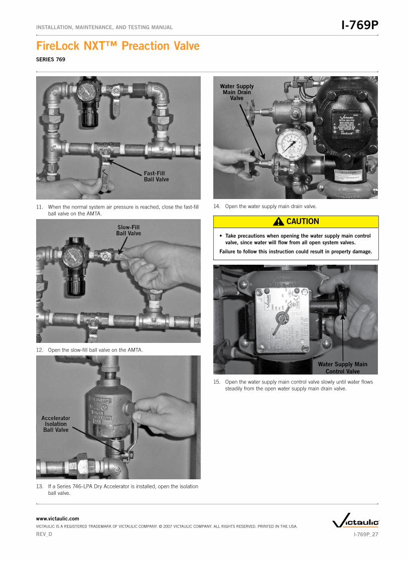
11. When the normal system air pressure is reached, close the fast-fill ball valve on the AMTA.
12. Open the slow-fill ball valve on the AMTA.
13. If a Series 746-LPA Dry Accelerator is installed, open the isolation ball valve.
14. Open the water supply main drain valve.
CAUTION
Take�precautions�when�opening�the�water�supply�main�control�•�valve,�since�water�will�flow�from�all�open�system�valves.
Failure�to�follow�this�instruction�could�result�in�property�damage.
Water Supply Main Control Valve
15. Open the water supply main control valve slowly until water flows steadily from the open water supply main drain valve.
REV_D
FireLock�NXT™�Preaction�ValveSERIES 769
I-769PINSTALLATION,�MAINTENANCE,�AND�TESTING�MANUAL
www.victaulic.comVICTAULIC IS A REGISTERED TRADEMARK OF VICTAULIC COMPANY. © 2007 VICTAULIC COMPANY. ALL RIGHTS RESERVED. PRINTED IN THE USA.
I-769P_27

16. Close the water supply main drain valve when a steady flow of water occurs.
Water Supply Main Control
Valve
17. Open the water supply main control valve fully.
18. Confirm that all valves are in their normal operating positions (refer to the table below).
ValveNormal�Operating�
Position
Diaphragm-Charge-Line Ball Valve Open
Alarm Test Ball Valve Closed
Water Supply Main Control Valve Open
Water Supply Main Drain Valve Closed
System Main Drain Valve Closed
Slow-Fill Ball Valve of the Victaulic AMTA (if applicable) Open
Fast-Fill Ball Valve of the Victaulic AMTA (if applicable) Closed
Isolation Ball Valve for Series 746-LPA Dry Accelerator (if applicable) Open
1/4-Turn Vent Ball Valve for Series 746-LPA Dry Accelerator (if appli-cable) Closed
19. Notify the authority having jurisdiction, remote station alarm monitors, and those in the affected area that the valve is back in service.
20. Provide test results to the authority having jurisdiction, if required.
I-769P_28
FireLock�NXT™�Preaction�ValveSERIES 769
I-769PINSTALLATION,�MAINTENANCE,�AND�TESTING�MANUAL
www.victaulic.comVICTAULIC IS A REGISTERED TRADEMARK OF VICTAULIC COMPANY. © 2007 VICTAULIC COMPANY. ALL RIGHTS RESERVED. PRINTED IN THE USA.
REV_D

REQUIRED�OPERATIONAL�(TRIP)�TESTSPARTIAL�OPERATIONAL�(TRIP)�TEST
WARNING�The�building�owner�or�their�representative�is�responsible�for�•�maintaining�the�fire�protection�system�in�proper�operating��condition.
To�ensure�proper�system�operation,�valves�must�be�inspected�•�in�accordance�with�current�NFPA-25�requirements�or�in�accor-dance�with�the�requirements�of�the�local�authority�having�jurisdiction�(whichever�is�more�stringent).�Always�refer�to�the�instructions�in�this�manual�for�additional�inspection�and�testing�requirements.
The�frequency�of�inspections�must�be�increased�in�the�pres-•�ence�of�contaminated�water�supplies,�corrosive/scaling�water�supplies,�and�corrosive�atmospheres.
Depressurize�and�drain�the�piping�system�before�attempting�to�•�install,�remove,�adjust,�or�maintain�any�Victaulic�products.
Failure�to�follow�these�instructions�could�cause�system�failure,�resulting�in�death,�serious�personal�injury,�and�property�damage.
Partial operational (trip) tests are required to confirm proper valve operation; however, this test does not confirm full system operation. Victaulic recommends performing the partial operational (trip) test annually (at minimum). NOTE: The frequency of the partial operational (trip) test must be increased in the presence of contaminated water supplies, corrosive/scaling water supplies, and corrosive atmospheres. In addition, the authority having jurisdiction in the area may require partial operational (trip) tests on a more frequent basis. Verify these requirements by contacting the authority having jurisdiction in the affected area.
1. Notify the authority having jurisdiction, remote station alarm monitors, and those in the affected area that the partial operational (trip) test will be performed.
2. Record the water supply pressure and system air pressure.
3. Open the water supply main drain valve fully to flush the water supply of any contaminants.
Water Supply Main Control Valve
4. Close the water supply main control valve to the point where additional closure will not provide flow through the water supply main drain valve.
Water Supply Main Control Valve
5. Open the water supply main control valve slowly until a small amount of water flows through the water supply main drain valve.
6. Close the water supply main drain valve.
REV_D
FireLock�NXT™�Preaction�ValveSERIES 769
I-769PINSTALLATION,�MAINTENANCE,�AND�TESTING�MANUAL
www.victaulic.comVICTAULIC IS A REGISTERED TRADEMARK OF VICTAULIC COMPANY. © 2007 VICTAULIC COMPANY. ALL RIGHTS RESERVED. PRINTED IN THE USA.
I-769P_29

7. Trip�the�valve�by�doing�one�of�the�following:
a. Energize the solenoid valve
b. Relieve the air pressure from the pilot line
c. Open the manual pull station
8. Confirm that the diaphragm charge line’s pressure drops to zero and that water is flowing through the auto drain to the drip cup.
Water Supply Main Control Valve
9. Close the water supply main control valve fully.
10. Close the remote system test valve (inspector’s test connection) or the system main drain valve. NOTE: The system main drain valve is shown above.
11. SHUT�OFF�THE�AIR�SUPPLY.
12. Close the diaphragm-charge-line ball valve.
13. Perform all steps in the “Placing the System in Service” section.
I-769P_30
FireLock�NXT™�Preaction�ValveSERIES 769
I-769PINSTALLATION,�MAINTENANCE,�AND�TESTING�MANUAL
www.victaulic.comVICTAULIC IS A REGISTERED TRADEMARK OF VICTAULIC COMPANY. © 2007 VICTAULIC COMPANY. ALL RIGHTS RESERVED. PRINTED IN THE USA.
REV_D

FULL�OPERATIONAL�(TRIP)�TEST
WARNING�The�building�owner�or�their�representative�is�responsible�for�•�maintaining�the�fire�protection�system�in�proper�operating��condition.
To�ensure�proper�system�operation,�valves�must�be�inspected�•�in�accordance�with�current�NFPA-25�requirements�or�in�accor-dance�with�the�requirements�of�the�local�authority�having�jurisdiction�(whichever�is�more�stringent).�Always�refer�to�the�instructions�in�this�manual�for�additional�inspection�and�testing�requirements.
The�frequency�of�inspections�must�be�increased�in�the�pres-•�ence�of�contaminated�water�supplies,�corrosive/scaling�water�supplies,�and�corrosive�atmospheres.
Depressurize�and�drain�the�piping�system�before�attempting�to�•�install,�remove,�adjust,�or�maintain�any�Victaulic�products.
Failure�to�follow�these�instructions�could�cause�system�failure,�resulting�in�death,�serious�personal�injury,�and�property�damage.
Victaulic recommends the full operational (trip) test every 3 years (at minimum). NOTE: The frequency of the full operational (trip) test must be increased in the presence of contaminated water supplies, corrosive/scaling water supplies, and corrosive atmospheres. This test allows a full flow of water into the sprinkler system; therefore, this test must be per-formed when there is no chance for freezing conditions. In addition, the authority having jurisdiction in the area may require full operational (trip) tests on a more frequent basis. Verify these requirements by contacting the authority having jurisdiction in the affected area.
1. Notify the authority having jurisdiction, remote station alarm monitors, and those in the affected area that the full operational (trip) test will be performed.
2. Record the water supply pressure and system air pressure.
3. Open the water supply main drain valve fully to flush the water supply of any contaminants.
4. Close the water supply main drain valve.
5. Trip�the�valve�by�doing�one�of�the�following:
a. Energize the solenoid valve
b. Relieve the air pressure from the pilot line
c. Open the manual pull station
6. Record the following:
a. Time between opening the remote system test valve (inspector’s test connection) to the operation of the preaction valve
b. System air pressure when the valve operated
c. Time from opening the remote system test valve (inspector’s test connection) to when water flows from the test connection’s outlet
d. All information required by the authority having jurisdiction
7. Confirm that all alarms operate properly.
8. Continue to run water until it is clear.
Water Supply Main Control Valve
9. Close the water supply main control valve.
REV_D
FireLock�NXT™�Preaction�ValveSERIES 769
I-769PINSTALLATION,�MAINTENANCE,�AND�TESTING�MANUAL
www.victaulic.comVICTAULIC IS A REGISTERED TRADEMARK OF VICTAULIC COMPANY. © 2007 VICTAULIC COMPANY. ALL RIGHTS RESERVED. PRINTED IN THE USA.
I-769P_31

10. Close the diaphragm-charge-line ball valve.
11. SHUT�OFF�THE�AIR�SUPPLY.
12. Open the system main drain valve to drain the system.
13. After the system is properly drained, close the remote system test valve (inspector’s test connection).
14. Close the system main drain valve.
15. Perform all steps in the “Placing the System in Service” section.
I-769P_32
FireLock�NXT™�Preaction�ValveSERIES 769
I-769PINSTALLATION,�MAINTENANCE,�AND�TESTING�MANUAL
www.victaulic.comVICTAULIC IS A REGISTERED TRADEMARK OF VICTAULIC COMPANY. © 2007 VICTAULIC COMPANY. ALL RIGHTS RESERVED. PRINTED IN THE USA.
REV_D

REQUIRED�INTERNAL�INSPECTIONInspect internal components on a frequency required by the current NFPA-25 code. The authority having jurisdiction in the area may require these inspections on a more frequent basis. Verify these requirements by contacting the authority having jurisdiction in the affected area.
WARNINGDepressurize�and�drain�the�piping�system�•�before�attempting�to�remove�the�cover�plate�from�the�valve.
Failure�to�follow�this�instruction�could�result�in�serious�personal�injury�and/or�property��damage.
CAUTIONAny�activities�that�require�taking�the�•�valve�out�of�service�may�eliminate�the�fire�protection�provided.
Before�servicing�or�testing�the�system,�•�notify�the�authority�having�jurisdiction.
Consideration�of�a�fire�patrol�should�be�•�given�in�the�affected�areas.
Failure�to�follow�these�instructions�could�result�in�serious�personal�injury�and/or�prop-erty��damage.
1. Notify the authority having jurisdiction, remote station alarm monitors, and those in the affected area that the system is being taken out of service.
2. Open the water supply main drain valve fully to flush the water supply of any contaminants.
3. Close the water supply main drain valve.
Water Supply Main Control Valve
4. Close the water supply main control valve to take the system out of service.
5. Open the water supply main drain valve.
6. Confirm that water is not flowing from the water supply main drain valve.
REV_D
FireLock�NXT™�Preaction�ValveSERIES 769
I-769PINSTALLATION,�MAINTENANCE,�AND�TESTING�MANUAL
www.victaulic.comVICTAULIC IS A REGISTERED TRADEMARK OF VICTAULIC COMPANY. © 2007 VICTAULIC COMPANY. ALL RIGHTS RESERVED. PRINTED IN THE USA.
I-769P_33

7. Close the diaphragm-charge-line ball valve.
8. Open the system main drain valve to drain any water that has accumulated and to release system air pressure.
NOTE: If the system has operated, open the remote system test valve (inspector’s test connection) and any auxiliary drain valves.
9. Close the slow-fill ball valve on the AMTA.
WARNING
Make�sure�the�valve�is�depressurized�and�•�drained�completely�before�the�cover�plate�bolts�are�removed.
The�cover�plate�could�blow�off�if�the�cover�plate�bolts�are�removed�while�the�valve�is�pressur-ized,�resulting�in�serious�personal�injury�and/or��property�damage.
10. OPEN�THE�MANUAL�PULL�STATION.
11. After all pressure is released from the system, loosen the cover plate bolts slowly. NOTE: DO NOT remove any cover plate bolts until all cover plate bolts are loosened.
11a. Remove all cover plate bolts, along with the cover plate and cover plate gasket. NOTE: The 1 1/2-inch/48.3-mm and 2-inch/60.3-mm valve sizes contain washers under the heads of the cover plate bolts. Keep these washers for re-installation.
12. Push the latch back (toward the diaphragm).
I-769P_34
FireLock�NXT™�Preaction�ValveSERIES 769
I-769PINSTALLATION,�MAINTENANCE,�AND�TESTING�MANUAL
www.victaulic.comVICTAULIC IS A REGISTERED TRADEMARK OF VICTAULIC COMPANY. © 2007 VICTAULIC COMPANY. ALL RIGHTS RESERVED. PRINTED IN THE USA.
REV_D

CAUTION
DO�NOT�use�solvents�or�abrasives�on�or�near�the�valve�body�•�seat�ring.
Failure�to�follow�this�instruction�could�prevent�the�clapper�from�sealing,�resulting�in�improper�valve�operation�and/or�valve��leakage.
13. Rotate the clapper out of the valve body. Inspect the clapper seal and seal-retaining ring. Wipe away any contaminants, dirt, and mineral deposits. Clean out any holes that are plugged in the valve-body seat ring. DO�NOT�USE�SOLVENTS�OR�ABRASIVES.
14. While the clapper is rotated out of the valve body, pull the latch forward to inspect the diaphragm. If the diaphragm shows any signs of wear or damage, replace it with a new, Victaulic-supplied diaphragm. Refer to the “Removing and Replacing the Diaphragm Assembly” section.
15. Inspect the clapper for freedom of movement and physical damage. Replace any damaged or worn parts by following the applicable instructions in the “Maintenance” section.
16. Re-install the cover plate by following the “Installing the Cover Plate Gasket and Cover Plate” section.
17. Place the system back in service by following the “Placing the System in Service” section.
REV_D
FireLock�NXT™�Preaction�ValveSERIES 769
I-769PINSTALLATION,�MAINTENANCE,�AND�TESTING�MANUAL
www.victaulic.comVICTAULIC IS A REGISTERED TRADEMARK OF VICTAULIC COMPANY. © 2007 VICTAULIC COMPANY. ALL RIGHTS RESERVED. PRINTED IN THE USA.
I-769P_35

MAINTENANCEThe following sections instruct on how to remove and replace internal valve components. Care must be taken to avoid damage to parts during removal and installation.
WARNING
Depressurize�and�drain�the�piping�system�•�before�attempting�to�remove�the�cover�plate�from�the�valve.
Failure�to�follow�this�instruction�could�result�in�serious�personal�injury�and/or�property��damage.
CAUTIONAny�activities�that�require�taking�the�•�valve�out�of�service�may�eliminate�the�fire�protection�provided.
Before�servicing�or�testing�the�system,�•�notify�the�authority�having�jurisdiction.
Consideration�of�a�fire�patrol�should�be�•�given�in�the�affected�areas.
Failure�to�follow�these�instructions�could�result�in�serious�personal�injury�and/or�prop-erty��damage.
REMOVING�AND�REPLACING�THE�CLAPPER�SEAL
1. Perform steps 1 – 12 of the “Required Internal Inspection” section.
2. Remove the seal assembly bolt/bolt seal from the clapper seal.
3. Remove the seal-retaining ring.
CAUTION
DO�NOT�pry�the�seal�washer�out�of�the�clapper�seal�from�the�•�inner�hole.
Failure�to�follow�this�instruction�could�damage�the�seal�washer,�resulting�in�improper�clapper�sealing�and�valve�leakage.
4. Pry the edge of the seal washer from inside the clapper seal, as shown above. DO�NOT�PRY�THE�SEAL�WASHER�OUT�FROM�THE�INNER�HOLE.
5. Remove the seal washer from the clapper seal. Dry up any moisture that is under the seal washer and on the clapper seal.
CAUTION
Use�only�Victaulic-supplied�replacement�parts.•�
Failure�to�follow�this�instruction�could�cause�improper�valve�operation,�resulting�in�property�damage.
I-769P_36
FireLock�NXT™�Preaction�ValveSERIES 769
I-769PINSTALLATION,�MAINTENANCE,�AND�TESTING�MANUAL
www.victaulic.comVICTAULIC IS A REGISTERED TRADEMARK OF VICTAULIC COMPANY. © 2007 VICTAULIC COMPANY. ALL RIGHTS RESERVED. PRINTED IN THE USA.
REV_D

6. Pry the clapper seal, along with the seal ring, out of the clapper. Inspect the clapper seal. If the clapper seal is torn or worn, replace it with a new, Victaulic-supplied clapper seal. If replacing the clapper seal assembly with a new assembly, skip to step 7.
6a. If�using�the�same�clapper�seal�assembly�and�the�seal�ring�was�removed�from�the�clapper�seal�in�the�previous�step: Re-insert the seal ring carefully underneath the outer lip of the clapper seal. Make sure the smaller diameter of the seal ring is toward the sealing surface of the clapper seal.
7. Insert the seal washer carefully underneath the sealing lip of the gasket.
8. Remove any contaminants, dirt, and mineral deposits from the clapper.
9. Install the clapper seal into the clapper carefully. Make sure the seal ring snaps into the clapper completely.
10. Place the seal-retaining ring onto the seal washer of the clapper seal. Install the seal-assembly bolt/bolt seal through the seal-retaining ring and clapper.
REV_D
FireLock�NXT™�Preaction�ValveSERIES 769
I-769PINSTALLATION,�MAINTENANCE,�AND�TESTING�MANUAL
www.victaulic.comVICTAULIC IS A REGISTERED TRADEMARK OF VICTAULIC COMPANY. © 2007 VICTAULIC COMPANY. ALL RIGHTS RESERVED. PRINTED IN THE USA.
I-769P_37

11. Tighten the seal-assembly bolt/bolt seal to the torque value, listed in the table below, to ensure a proper seal.
REQUIRED�SEAL-ASSEMBLY�BOLT/BOLT�SEAL�TORQUES
Size Torque
Nominal�Size inches
Actual Outside�Diameter
inchesmm
inch-lbsN•m
1 ½ 1.900 4048.3 5
2 2.375 4060.3 5
2 ½ 2.875 9073.0 10
76.1 mm 3.000 9076.1 10
3 3.500 9088.9 10
4 4.500 110114.3 12
165.1 mm 6.500 160165.1 18
6 6.625 160168.3 18
8 8.625 160219.1 18
12. Replace the cover plate by following the “Installing the Cover Plate Gasket and Cover Plate” section.
13. Place the system back in service by following the “Placing the System in Service” section.
REMOVING�AND�REPLACING�THE�CLAPPER�ASSEMBLY
1. Perform steps 1 – 12 of the “Required Internal Inspection” section.
2. Remove the clapper shaft bushings from the valve body.
3. Remove the clapper shaft. NOTE: As the shaft is being removed, the clapper spring will drop out of position. Keep the clapper spring for re-installation.
4. Remove the clapper from the valve body.
I-769P_38
FireLock�NXT™�Preaction�ValveSERIES 769
I-769PINSTALLATION,�MAINTENANCE,�AND�TESTING�MANUAL
www.victaulic.comVICTAULIC IS A REGISTERED TRADEMARK OF VICTAULIC COMPANY. © 2007 VICTAULIC COMPANY. ALL RIGHTS RESERVED. PRINTED IN THE USA.
REV_D
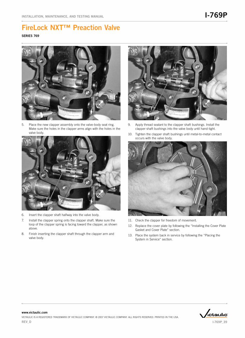
5. Place the new clapper assembly onto the valve-body seat ring. Make sure the holes in the clapper arms align with the holes in the valve body.
6. Insert the clapper shaft halfway into the valve body.
7. Install the clapper spring onto the clapper shaft. Make sure the loop of the clapper spring is facing toward the clapper, as shown above.
8. Finish inserting the clapper shaft through the clapper arm and valve body.
9. Apply thread sealant to the clapper shaft bushings. Install the clapper shaft bushings into the valve body until hand-tight.
10. Tighten the clapper shaft bushings until metal-to-metal contact occurs with the valve body.
11. Check the clapper for freedom of movement.
12. Replace the cover plate by following the “Installing the Cover Plate Gasket and Cover Plate” section.
13. Place the system back in service by following the “Placing the System in Service” section.
REV_D
FireLock�NXT™�Preaction�ValveSERIES 769
I-769PINSTALLATION,�MAINTENANCE,�AND�TESTING�MANUAL
www.victaulic.comVICTAULIC IS A REGISTERED TRADEMARK OF VICTAULIC COMPANY. © 2007 VICTAULIC COMPANY. ALL RIGHTS RESERVED. PRINTED IN THE USA.
I-769P_39
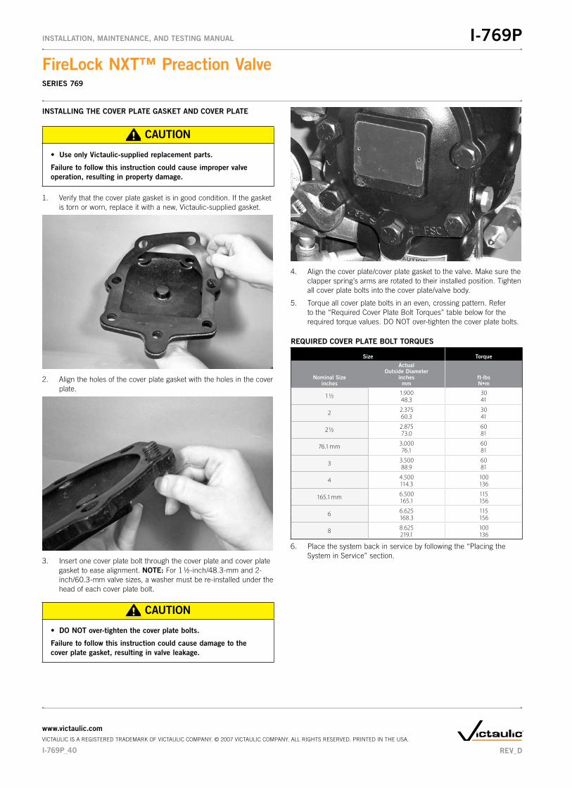
INSTALLING�THE�COVER�PLATE�GASKET�AND�COVER�PLATE
CAUTION
Use�only�Victaulic-supplied�replacement�parts.•�
Failure�to�follow�this�instruction�could�cause�improper�valve�operation,�resulting�in�property�damage.
1. Verify that the cover plate gasket is in good condition. If the gasket is torn or worn, replace it with a new, Victaulic-supplied gasket.
2. Align the holes of the cover plate gasket with the holes in the cover plate.
3. Insert one cover plate bolt through the cover plate and cover plate gasket to ease alignment. NOTE: For 1 1/2-inch/48.3-mm and 2-inch/60.3-mm valve sizes, a washer must be re-installed under the head of each cover plate bolt.
CAUTION
DO�NOT�over-tighten�the�cover�plate�bolts.•�
Failure�to�follow�this�instruction�could�cause�damage�to�the�cover�plate�gasket,�resulting�in�valve�leakage.
4. Align the cover plate/cover plate gasket to the valve. Make sure the clapper spring’s arms are rotated to their installed position. Tighten all cover plate bolts into the cover plate/valve body.
5. Torque all cover plate bolts in an even, crossing pattern. Refer to the “Required Cover Plate Bolt Torques” table below for the required torque values. DO NOT over-tighten the cover plate bolts.
REQUIRED�COVER�PLATE�BOLT�TORQUES
Size Torque
Nominal�Size inches
Actual Outside�Diameter
inchesmm
ft-lbsN•m
1 ½ 1.900 3048.3 41
2 2.375 3060.3 41
2 ½ 2.875 6073.0 81
76.1 mm 3.000 6076.1 81
3 3.500 6088.9 81
4 4.500 100114.3 136
165.1 mm 6.500 115165.1 156
6 6.625 115168.3 156
8 8.625 100219.1 136
6. Place the system back in service by following the “Placing the System in Service” section.
I-769P_40
FireLock�NXT™�Preaction�ValveSERIES 769
I-769PINSTALLATION,�MAINTENANCE,�AND�TESTING�MANUAL
www.victaulic.comVICTAULIC IS A REGISTERED TRADEMARK OF VICTAULIC COMPANY. © 2007 VICTAULIC COMPANY. ALL RIGHTS RESERVED. PRINTED IN THE USA.
REV_D

REMOVING�AND�REPLACING�THE�DIAPHRAGM�ASSEMBLY
1. Remove the system from service by following steps 1 – 11 of the “Required Internal Inspection” section.
2. Break the unions that connect the trim to the diaphragm cover. Refer to the applicable trim drawing for details.
3. Remove the cap screws from the diaphragm cover, and pull the diaphragm cover/trim off the valve.
4. Remove the diaphragm from the valve body.
5. Clean the back of the valve body to remove any debris that may interfere with proper diaphragm seating.
5a. Clean the inside of the diaphragm cover to remove any foreign material.
CAUTION
Use�caution�when�installing�a�new�diaphragm�into�the�valve�•�body.
Failure�to�follow�this�instruction�could�cause�damage�to�the��diaphragm,�resulting�in�improper�valve�operation�and�valve��leakage.
6. Replace the diaphragm with a new, Victaulic-supplied diaphragm. Align the holes in the diaphragm with the holes in the valve body. Be careful not to damage the diaphragm during installation.
7. Align the holes of the diaphragm cover with the holes in the dia-phragm/valve body. Tighten all cap screws into the diaphragm cover/valve body.
8. Re-attach the trim at the unions that were loosened in step 2. Refer to the applicable trim drawing for details. MAKE�SURE�ALL�UNIONS�THAT�WERE�LOOSENED�TO�PERMIT�ACCESS�TO�THE�DIAPHRAGM�COVER�ARE�RE-TIGHTENED�BEFORE�ATTEMPTING�TO�PLACE�THE�SYSTEM�BACK�IN�SERVICE.
9. Place the system back in service by following the “Placing the System in Service” section.
REV_D
FireLock�NXT™�Preaction�ValveSERIES 769
I-769PINSTALLATION,�MAINTENANCE,�AND�TESTING�MANUAL
www.victaulic.comVICTAULIC IS A REGISTERED TRADEMARK OF VICTAULIC COMPANY. © 2007 VICTAULIC COMPANY. ALL RIGHTS RESERVED. PRINTED IN THE USA.
I-769P_41

REPLACING�THE�STRAINER�SCREEN�FOR�SERIES�776�LOW-PRESSURE�ACTUATORS
1. Remove the system from service by following steps 1 – 11 of the “Required Internal Inspection” section.
2. Remove the Series 776 Low-Pressure Actuator from the trim. Refer to the applicable trim drawing for details.
3. Remove the strainer assembly from the Series 776 Low-Pressure Actuator, as shown above. Discard the strainer screen only.
CAUTION
DO�NOT�re-use�strainer�screens.�After�removal,�the�old�•��strainer�screen�must�be�replaced�with�a�new,�Victaulic-�supplied�screen.
Failure�to�follow�this�instruction�could�cause�improper�valve�operation,�resulting�in�property�damage.
4. Use only a new, Victaulic-supplied strainer screen. Insert the strainer screen into the strainer assembly.
5. Install the strainer assembly into the Series 776 Low-Pressure Actuator carefully. Avoid damage to the o-ring seals.
6. Re-install the Series 776 Low-Pressure Actuator into the trim. Refer to the applicable trim drawing for details.
7. Place the system back in service by following the “Placing the System in Service” section.
I-769P_42
FireLock�NXT™�Preaction�ValveSERIES 769
I-769PINSTALLATION,�MAINTENANCE,�AND�TESTING�MANUAL
www.victaulic.comVICTAULIC IS A REGISTERED TRADEMARK OF VICTAULIC COMPANY. © 2007 VICTAULIC COMPANY. ALL RIGHTS RESERVED. PRINTED IN THE USA.
REV_D

TROUBLESHOOTING�–�SERIES�776�LOW-PRESSURE�ACTUATOR
Problem Possible�Cause Solution
When the Auto Vent Sleeve of the Series 776 Low-Pressure Actuator is pulled up, the screw does not stay set in the “UP” position.
The Series 776 Low-Pressure Actuator is not receiving enough air. Increase the air pressure going into the Series 776 Low-Pressure Actuator.
The Series 776 Low-Pressure Actuator has a broken seal. If the above procedure does not work, contact Victaulic.
Water is leaking through the Series 776 Low-Pressure Actuator. The air chamber of the Series 776 Low-Pressure Actuator is not set. Make sure the vent seal of the Series 776 Low-Pressure Actuator is in the set position and the air chamber is pressurized.
The strainer on the Series 776 Low-Pressure Actuator is clogged. Replace the strainer screen of the Series 776 Low-Pressure Actuator. Refer to the “Replacing the Strainer Screen for Series 776 Low-Pressure Actuators” section.
The Series 776 Low-Pressure Actuator has a ripped diaphragm. If water still leaks through the Series 776 after performing the above procedures, contact Victaulic.
No water is passing through the Series 776 Low-Pressure Actuator. The strainer on the diaphragm charge line is clogged. Disassemble and clean the diaphragm charge line strainer. Refer to the applicable trim drawing for details.
TROUBLESHOOTING�–�SERIES�753-E�SOLENOID�VALVE
Problem Possible�Cause Solution
No water is passing through the Series 753-E Solenoid Valve. The strainer on the diaphragm charge line is clogged. Disassemble and clean the diaphragm charge line strainer. Refer to the applicable trim drawing for details.
The Series 776 Low Pressure Actuator does not open. No power is going to the solenoid. Check all electrical connections to make sure power is being supplied to the solenoid.
TROUBLESHOOTING�–�SERIES�746-LPA�DRY�ACCELERATOR
Problem Possible�Cause Solution
The valve operates without sprinkler activation. There is a loss of air pressure in the lower inlet chamber of the Series 746-LPA Dry Accelerator.
Check for air loss at the lower chamber seal. If a leak is present, turn the adjustment nut counterclockwise to seal.
Check for any leaks in the system and trim. Confirm that the AMTA is operating properly.
The Series 746-LPA Dry Accelerator does not operate within a 5-psi/34-kPa/0.3-Bar pressure drop in system air pressure.
There is a loss of air pressure in the upper air chamber of the Series 746-LPA Dry Accelerator.
Apply soapy water to all joints around the Series 746-LPA Dry Accelerator to check for leaks. Repair any leaks and re-test.
The air decay rate of the system is too slow. Make sure there are no restrictions in the remote system test valve (inspector’s test connection).
If the above procedures do not work, contact Victaulic.
The Series 746-LPA Dry Accelerator does not set up properly (cannot get pressure on the upper gauge, and the button pops up immedi-ately when pressure is introduced).
The Series 746-LPA Dry Accelerator is installed upside-down. Remove the Series 746-LPA Dry Accelerator from the trim, and turn the unit around so that the vent seal “button” is facing down (toward the Series 776 Low-Pressure Actuator).
REV_D
FireLock�NXT™�Preaction�ValveSERIES 769
I-769PINSTALLATION,�MAINTENANCE,�AND�TESTING�MANUAL
www.victaulic.comVICTAULIC IS A REGISTERED TRADEMARK OF VICTAULIC COMPANY. © 2007 VICTAULIC COMPANY. ALL RIGHTS RESERVED. PRINTED IN THE USA.
I-769P_43

TROUBLESHOOTING�–�SYSTEM
Problem Possible�Cause Solution
The valve operates without sprinkler activation. There is a loss of air pressure in the system or trim. Check for any leaks in the system and trim. Confirm that the AMTA is operating properly. Consider installing a low-air supervisory switch.
The pressure switch on the air compressor is set too low, or the compressor is not operating properly.
Increase the “ON” setting of the air compressor’s pressure switch, and check the air compressor for proper operation.
Water is leaking from the drip check located in the alarm line. Water is getting past the clapper seal and into the intermediate chamber of the valve.
Check the clapper seal and valve body seat ring for physical damage and foreign material.
Water is under the clapper seal. Inspect the clapper seal to make sure no water is under the seal. If water is present, remove and replace the seal. Refer to the “Removing and Replac-ing the Clapper Seal” section.
Air is leaking from the drip check located in the alarm line. Air is getting past the clapper seal and into the intermediate chamber of the valve.
Check the clapper seal and valve body seat ring for physical damage and foreign material.
Water is under the clapper seal. Inspect the clapper seal to make sure no water is under the seal. If water is present, remove and replace the seal. Refer to the “Removing and Replac-ing the Clapper Seal” section.
The clapper will not latch closed. There is no water pressure on the diaphragm. Check the water pressure in the diaphragm charge line. Make sure the restrictor in the diaphragm charge line is clean.
The Auto Drain is not set. Set the Auto Drain by pulling up on the Auto Drain Sleeve.
Water is leaking from the diaphragm assembly. The diaphragm is damaged. Contact Victaulic.
Air is leaking from the diaphragm assembly. The diaphragm is damaged. Contact Victaulic.
I-769P_44
FireLock�NXT™�Preaction�ValveSERIES 769
I-769PINSTALLATION,�MAINTENANCE,�AND�TESTING�MANUAL
www.victaulic.comVICTAULIC IS A REGISTERED TRADEMARK OF VICTAULIC COMPANY. © 2007 VICTAULIC COMPANY. ALL RIGHTS RESERVED. PRINTED IN THE USA.
REV_D


WCAS-7EFFBU
FireLock�NXT™�Preaction�ValveSERIES 769 NON-INTERLOCKED,�PNEUMATIC�RELEASE�WITH�SERIES�776�LOW-PRESSURE�ACTUATOR NON-INTERLOCKED,�PNEUMATIC/ELECTRIC�RELEASE�WITH�SERIES�776�LOW-PRESSURE�ACTUATOR�AND�SERIES�753-E�SOLENOID�VALVE SINGLE-INTERLOCKED,�PNEUMATIC�RELEASE�WITH�SERIES�776�LOW-PRESSURE�ACTUATOR SINGLE-INTERLOCKED,�ELECTRIC�RELEASE�WITH�SERIES�753-E�SOLENOID�VALVE DOUBLE-INTERLOCKED,�ELECTRIC�(ELECTRIC-PNEUMATIC/ELECTRIC)�RELEASE�WITH�SERIES�753-E�SOLENOID�VALVE
I-769PINSTALLATION,�MAINTENANCE,�AND�TESTING�MANUAL
I-769P
For complete contact information, visit www.victaulic.comI-769P�����4259�REV�D������UPDATED�05/2008������Z000769P00VICTAULIC IS A REGISTERED TRADEMARK OF VICTAULIC COMPANY. © 2007 VICTAULIC COMPANY. ALL RIGHTS RESERVED. PRINTED IN THE USA.