technical data 4” model g-4000p preaction … · technical data may 28, 2013 4” model g-4000p...
TRANSCRIPT

TECHNICAL DATA
May 28, 2013
4” MoDEL G-4000P PrEACTIoN wITH ELECTrIC rELEAsE
The Viking Corporation, 210 N Industrial Park Drive, Hastings MI 49058Telephone: 269-945-9501 Technical services: 877-384-5464 Fax: 269-818-1680 Email: [email protected]
Preaction 325a
1. DEsCrIPTIoNThe 4” Model G-4000P Electric Release Preaction System Riser Assembly can be used as a Single Interlock Preaction System with Electric Release, or as a Double Interlock Preaction System with Electric/Pneu-Lectric Release. These �reaction systems are commonly usedThese �reaction systems are commonly used where it is im�ortant to control accidental water discharge due to inadvertent damage to the s�rinkler �i�ing. The small �ro�ile, lightweight, �ilot o�erated �iking G-4000P �alve comesThe small �ro�ile, lightweight, �ilot o�erated �iking G-4000P �alve comes com�lete as shown in Figure 8. This pilot operated externally reset valve also includes an internal check diaphragm, which eliminates the need for a separate check valve being installed in the system riser.A. Viking supervised single-Interlocked Electric release Preaction systems Utilizing the Viking G-4000P Valve
The system �i�ing is �ressurized with air or nitrogen as required by NFPA 13 �or su-�ervisory �ur�oses only. �iking recommends a minimum o� 15 to 20 �si (1.0 to 1.4 bar) �or su�ervisory air �ressure �or single interlock systems (re�er to Table 2 �or double interlock systems). This �eature serves to �revent undetected leaks on the system �i�-ing network. I� the system �i�ing or a s�rinkler is damaged, the su�ervisory �ressure is reduced and a “low air” su�ervisory alarm is activated. Electrically released �reaction systems require a 24 �DC normally closed electric so-lenoid valve controlled by an a��roved release control �anel with com�atible detection system. In �ire conditions, when the detection system o�erates, the system control �anel energizes the solenoid valve o�en. When the solenoid o�ens, the �riming water is relieved �rom the internal �rime chamber assembly. The �rime chamber assembly colla�ses, and water �asses through the G-4000P �alve and internal check dia�hragm to the system �i�ing network. The entire s�rinkler system �ills with water. The s�rinkler �i�ing will remain �illed with water until a s�rinkler o�erates.
B. Viking supervised Double-Interlocked Electric/Pneu-Lectric release Preaction systems Utilizing the Viking Model G-4000P Valve.
The system �i�ing is �ressurized with air or nitrogen to serve both as a means o� su�ervising the integrity o� the �i�ing network and as one �ortion o� the system release o�eration. This �eature serves to �revent undetected leaks on the system �i�ing net-work. I� the system �i�ing or a s�rinkler is damaged, the su�ervisory �ressure is reduced and a “low air” su�ervisory alarm is activated. The 24 �DC normally closed electric solenoid and an additional “low air” alarm switch are connected to a com�atible release24 �DC normally closed electric solenoid and an additional “low air” alarm switch are connected to a com�atible releaseelectric solenoid and an additional “low air” alarm switch are connected to a com�atible release control �anel and com�atible detection devices. The release control �anel is �rogrammed so that a signal �rom both a release device and the low air alarm switch must be received be�ore the solenoid is allowed to o�en. The air �ressure switch has two inde�endently o�erating connections. The high side is wired as a low air su�ervisory switch, and the low side is wired as low air alarm. In �ire conditions, a detection device and the low air alarm switch must o�erate in order to o�en the solenoid valve. When the solenoid o�ens, �riming water is relieved �rom the G-4000P �alve’s internal �rime chamber assembly. The �rime chamber assembly is �orced o�en by the system water su��ly and water �asses through the G-4000P valve and internal check dia�hragm to the system �i�ing network. The entire s�rinkler system �ills with water.
2. LIsTING AND APProVALscULus Listed: �LFT
FM Approved: Preaction S�rinkler Systems
3. TECHNICAL DATAspecifications:Pressure Rating: 250 PSI (17.2 Bar) Water Working PressureFactory Hydrostatically Tested to: 500 �si (34.5 bar)Friction Loss (Given in �eet o� Schedule 40 �i�e based on Hazen & Williams �ormula C = 120): Model G-4000P �alve: 31.2’ 12” Section o� Pi�e: 1’ Water Su��ly Control �alve: 15’Model G-4000P �alve CCv Factor: 341�alve Color: BlackMaterial specifications:Re�er to Figure 11.
�iking Technical Data may be �ound on The �iking Cor�oration’s Web site at
htt�://www.vikinggrou�inc.com.The Web site may include a more recent
edition o� this Technical Data Page.
Q = Cv √ ∆PS
Form No. F_111608
Q = Flow
Cv = Flow Factor (GPM/1 PSI ∆P)
∆P = Pressure Loss through �alve
S = S�eci�ic Gravity o� Fluid
Revised �age re�laces �age 325a-m, dated Se�tember 2, 2010. (Revised �igure 11 and re�lacement �arts com�onents.)
TECHNICAL DATA
May 28, 2013
The Viking Corporation, 210 N Industrial Park Drive, Hastings MI 49058Telephone: 269-945-9501 Technical services: 877-384-5464 Fax: 269-818-1680 Email: [email protected]
Preaction 325b
4” MoDEL G-4000P PrEACTIoN wITH ELECTrIC rELEAsE
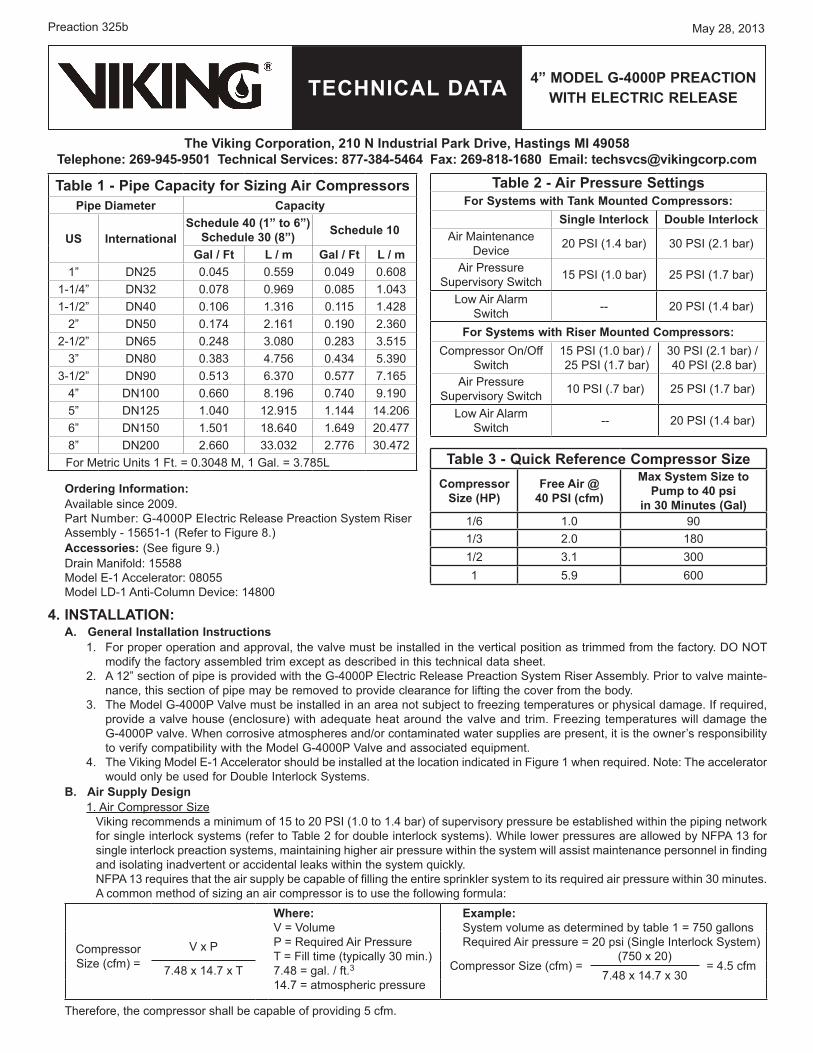
ordering Information:Available since 2009.Part Number: G-4000P Electric Release Preaction System RiserAssembly - 15651-1 (Re�er to Figure 8.)Accessories: (See �igure 9.)Drain Mani�old: 15588Model E-1 Accelerator: 08055 Model LD-1 Anti-Column Device: 14800
4. INsTALLATIoN:A. General Installation Instructions
1. For �ro�er o�eration and a��roval, the valve must be installed in the vertical �osition as trimmed �rom the �actory. DO NOT modi�y the �actory assembled trim exce�t as described in this technical data sheet.
2. A 12” section o� �i�e is �rovided with the G-4000P Electric Release Preaction System Riser Assembly. Prior to valve mainte-nance, this section o� �i�e may be removed to �rovide clearance �or li�ting the cover �rom the body.
3. The Model G-4000P �alve must be installed in an area not subject to �reezing tem�eratures or �hysical damage. I� required, �rovide a valve house (enclosure) with adequate heat around the valve and trim. Freezing tem�eratures will damage the G-4000P valve. When corrosive atmos�heres and/or contaminated water su��lies are �resent, it is the owner’s res�onsibility to veri�y com�atibility with the Model G-4000P �alve and associated equi�ment.
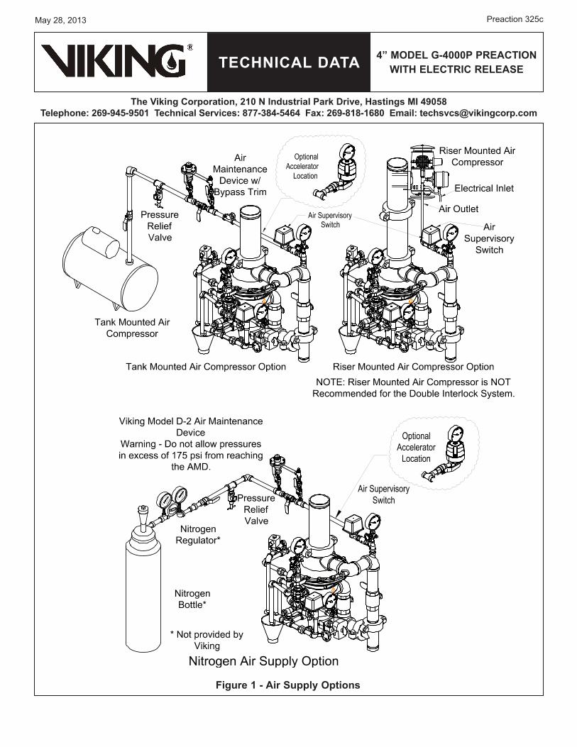
4. The �iking Model E-1 Accelerator should be installed at the location indicated in Figure 1 when required. Note: The accelerator would only be used �or Double Interlock Systems.
B. Air supply Design1. Air Com�ressor Size
�iking recommends a minimum o� 15 to 20 PSI (1.0 to 1.4 bar) o� su�ervisory �ressure be established within the �i�ing network �or single interlock systems (re�er to Table 2 �or double interlock systems). While lower �ressures are allowed by NFPA 13 �or single interlock �reaction systems, maintaining higher air �ressure within the system will assist maintenance �ersonnel in �inding and isolating inadvertent or accidental leaks within the system quickly.NFPA 13 requires that the air su��ly be ca�able o� �illing the entire s�rinkler system to its required air �ressure within 30 minutes. A common method o� sizing an air com�ressor is to use the �ollowing �ormula:
where:� = �olumeP = Required Air PressureT = Fill time (ty�ically 30 min.)7.48 = gal. / �t.314.7 = atmos�heric �ressure
Example:System volume as determined by table 1 = 750 gallonsRequired Air �ressure = 20 �si (Single Interlock System)Com�ressor
Size (c�m) = � x P
7.48 x 14.7 x T
There�ore, the com�ressor shall be ca�able o� �roviding 5 c�m.
Table 1 - Pipe Capacity for sizing Air CompressorsPipe Diameter Capacity
Us Internationalschedule 40 (1” to 6”)
schedule 30 (8”) schedule 10
Gal / Ft L / m Gal / Ft L / m1” DN25 0.045 0.559 0.049 0.608
1-1/4” DN32 0.078 0.969 0.085 1.0431-1/2” DN40 0.106 1.316 0.115 1.428
2” DN50 0.174 2.161 0.190 2.3602-1/2” DN65 0.248 3.080 0.283 3.515
3” DN80 0.383 4.756 0.434 5.3903-1/2” DN90 0.513 6.370 0.577 7.165
4” DN100 0.660 8.196 0.740 9.1905” DN125 1.040 12.915 1.144 14.2066” DN150 1.501 18.640 1.649 20.4778” DN200 2.660 33.032 2.776 30.472For Metric Units 1 Ft. = 0.3048 M, 1 Gal. = 3.785L Table 3 - Quick reference Compressor size
Compressor size (HP)
Free Air @ 40 PsI (cfm)
Max system size toPump to 40 psi
in 30 Minutes (Gal)1/6 1.0 901/3 2.0 1801/2 3.1 3001 5.9 600
Table 2 - Air Pressure settingsFor systems with Tank Mounted Compressors:
single Interlock Double InterlockAir Maintenance
Device 20 PSI (1.4 bar) 30 PSI (2.1 bar)
Air PressureSu�ervisory Switch 15 PSI (1.0 bar) 25 PSI (1.7 bar)
Low Air Alarm Switch -- 20 PSI (1.4 bar)
For systems with riser Mounted Compressors:Com�ressor On/O��
Switch15 PSI (1.0 bar) / 25 PSI (1.7 bar)
30 PSI (2.1 bar) / 40 PSI (2.8 bar)
Air Pressure Su�ervisory Switch 10 PSI (.7 bar) 25 PSI (1.7 bar)
Low Air Alarm Switch -- 20 PSI (1.4 bar)
Com�ressor Size (c�m) = (750 x 20)
= 4.5 c�m7.48 x 14.7 x 30
TECHNICAL DATA
May 28, 2013
4” MoDEL G-4000P PrEACTIoN wITH ELECTrIC rELEAsE
The Viking Corporation, 210 N Industrial Park Drive, Hastings MI 49058Telephone: 269-945-9501 Technical services: 877-384-5464 Fax: 269-818-1680 Email: [email protected]
Preaction 325c
Figure 1 - Air supply options
TECHNICAL DATA
May 28, 2013
The Viking Corporation, 210 N Industrial Park Drive, Hastings MI 49058Telephone: 269-945-9501 Technical services: 877-384-5464 Fax: 269-818-1680 Email: [email protected]
Preaction 325d
4” MoDEL G-4000P PrEACTIoN wITH ELECTrIC rELEAsE
NoTE: �iking recommends tank-mounted air com�ressors �or Double Interlock Electric/Pneu-Lectric Release Preaction Systems.2. Nitrogen Cylinder Gas Su��ly (See Figure 1.)
Nitrogen may be used in �lace o� air com�ressors. Nitrogen is su��lied in �ressurized cylinders in various sizes and �ressures. Some o� the most common are 122 Cu. Ft. at 1900 PSI (3455 L at 131 bar), 225 Cu. Ft. at 2100 PSI (6372 L at 145 bar), and 280 Cu. Ft. at 2300 PSI (7930 L at 159 bar). When nitrogen cylinders are used as a �rimary air su��ly, s�are cylinders should be �urnished and located at the valve location. To determine the a��roximate amount o� nitrogen to be �urnished, the �ollowing �ormula may be used:
S�ecial attention must be given to systems em�loying a bottled-gas su��ly. Because only a limited amount o� gas is available, small leaks that normally would go unnoticed in systems being su��lied by mechanical com�ressors, can become critical to the system’s overall �er�ormance. I� the system is to �unction at tem�eratures as low as -40 °F (-40 °C), and, i� bottled nitrogen is the gas su��ly, the system is �articularly susce�tible to leakage, and s�ecial care should be taken to ensure against leaks throughout the entire system.
C. Air supply Installation1. Install the required air su��ly as described in section 4.B. The size o� the com�ressor and amount o� air required should be de-
termined in accordance with Tables 1 - 3. The air or nitrogen su��ly to the �reaction system must be clean, dry, and oil �ree.2. Automatic air su��lies must be regulated, restricted, and �rom a continuous source. A �iking air maintenance device should
be installed on each system equi��ed with a tank-mounted com�ressor, �lant air, or nitrogen. For com�ressors with a ca-�acity less than 5.5 �t3/min at 10 �sig (0.154 m(0.154 m3/min at 0.69 bar), NFPA 13 does not require an air maintenance device. In NFPA 13 does not require an air maintenance device. In addition, an air maintenance device should not be used with riser mounted com�ressors as this can lead to com�ressor “short cycling”. �iking recommends using a tank-mounted com�ressor with air maintenance device. This can become critical whenThis can become critical when accelerators are installed on the system.
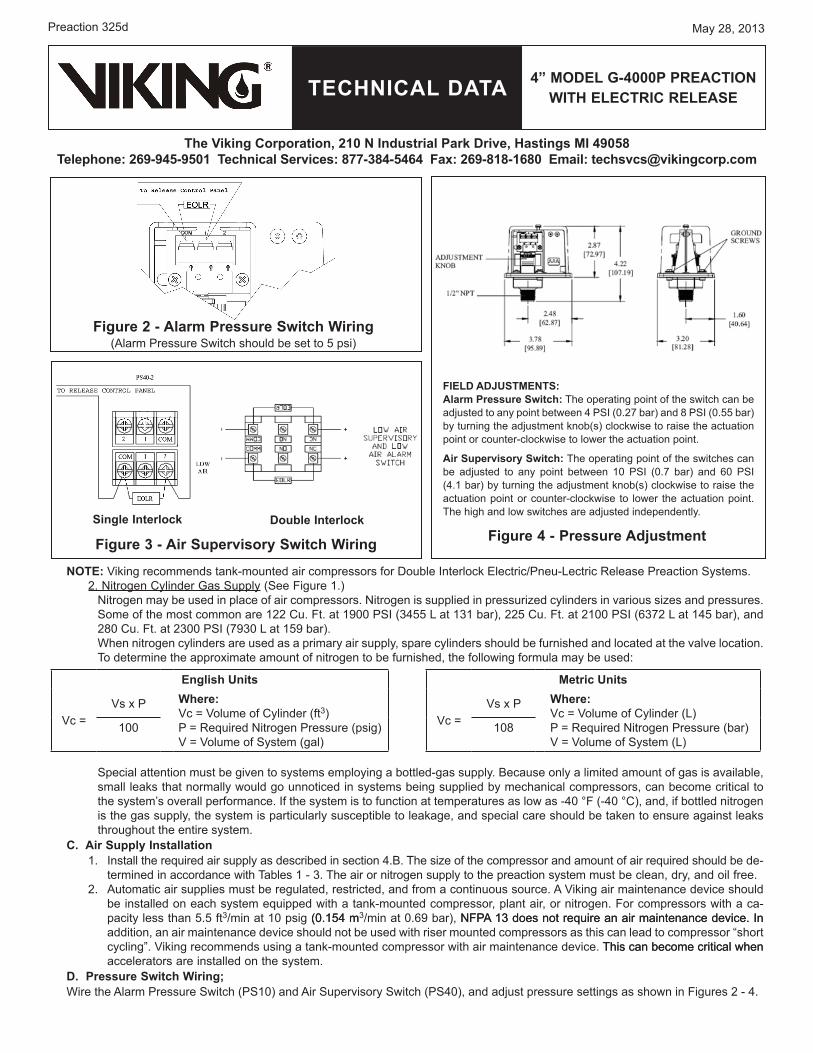
D. Pressure switch wiring;Wire the Alarm Pressure Switch (PS10) and Air Su�ervisory Switch (PS40), and adjust �ressure settings as shown in Figures 2 - 4.
Figure 4 - Pressure Adjustment
Figure 2 - Alarm Pressure switch wiring(Alarm Pressure Switch should be set to 5 �si)
FIELD ADJUsTMENTs: Alarm Pressure switch: The o�erating �oint o� the switch can be adjusted to any �oint between 4 PSI (0.27 bar) and 8 PSI (0.55 bar) by turning the adjustment knob(s) clockwise to raise the actuation �oint or counter-clockwise to lower the actuation �oint.
Air supervisory switch: The o�erating �oint o� the switches can be adjusted to any �oint between 10 PSI (0.7 bar) and 60 PSI (4.1 bar) by turning the adjustment knob(s) clockwise to raise the actuation �oint or counter-clockwise to lower the actuation �oint. The high and low switches are adjusted inde�endently.
English Units
�c = �s x P where:
�c = �olume o� Cylinder (�t3)P = Required Nitrogen Pressure (�sig)� = �olume o� System (gal)
100
Metric Units
�c = �s x P where:
�c = �olume o� Cylinder (L)P = Required Nitrogen Pressure (bar)� = �olume o� System (L)
108
Figure 3 - Air supervisory switch wiring
single Interlock Double Interlock
TECHNICAL DATA
May 28, 2013
4” MoDEL G-4000P PrEACTIoN wITH ELECTrIC rELEAsE
The Viking Corporation, 210 N Industrial Park Drive, Hastings MI 49058Telephone: 269-945-9501 Technical services: 877-384-5464 Fax: 269-818-1680 Email: [email protected]
Preaction 325e
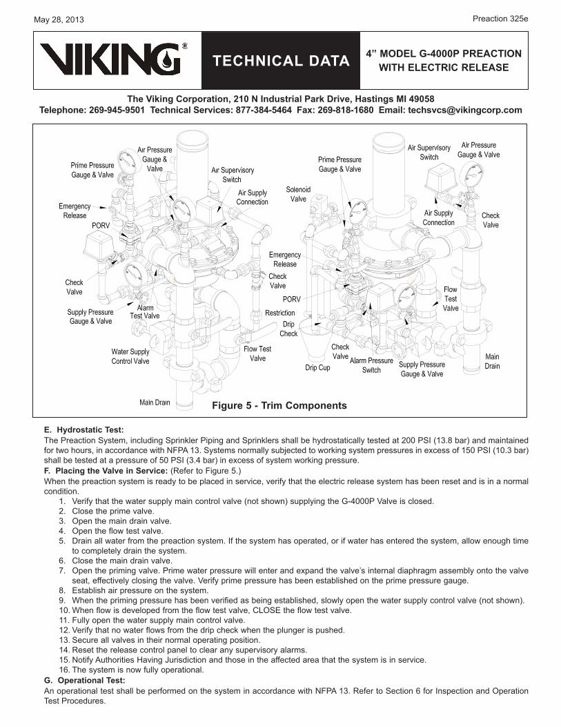
Figure 5 - Trim Components
E. Hydrostatic Test:The Preaction System, including S�rinkler Pi�ing and S�rinklers shall be hydrostatically tested at 200 PSI (13.8 bar) and maintained �or two hours, in accordance with NFPA 13. Systems normally subjected to working system �ressures in excess o� 150 PSI (10.3 bar) shall be tested at a �ressure o� 50 PSI (3.4 bar) in excess o� system working �ressure.F. Placing the Valve in service: (Re�er to Figure 5.)When the �reaction system is ready to be �laced in service, veri�y that the electric release system has been reset and is in a normal condition.
1. �eri�y that the water su��ly main control valve (not shown) su��lying the G-4000P �alve is closed.2. Close the �rime valve.3. O�en the main drain valve.4. O�en the �low test valve.5. Drain all water �rom the �reaction system. I� the system has o�erated, or i� water has entered the system, allow enough time
to com�letely drain the system. 6. Close the main drain valve.7. O�en the �riming valve. Prime water �ressure will enter and ex�and the valve’s internal dia�hragm assembly onto the valve
seat, e��ectively closing the valve. �eri�y �rime �ressure has been established on the �rime �ressure gauge.8. Establish air �ressure on the system.9. When the �riming �ressure has been veri�ied as being established, slowly o�en the water su��ly control valve (not shown).10. When �low is develo�ed �rom the �low test valve, CLOSE the �low test valve.11. Fully o�en the water su��ly main control valve.12. �eri�y that no water �lows �rom the dri� check when the �lunger is �ushed.13. Secure all valves in their normal o�erating �osition.14. Reset the release control �anel to clear any su�ervisory alarms.15. Noti�y Authorities Having Jurisdiction and those in the a��ected area that the system is in service.16. The system is now �ully o�erational.
G. operational Test:An o�erational test shall be �er�ormed on the system in accordance with NFPA 13. Re�er to Section 6 �or Ins�ection and O�eration Test Procedures.

TECHNICAL DATA
May 28, 2013
The Viking Corporation, 210 N Industrial Park Drive, Hastings MI 49058Telephone: 269-945-9501 Technical services: 877-384-5464 Fax: 269-818-1680 Email: [email protected]
Preaction 325�
4” MoDEL G-4000P PrEACTIoN wITH ELECTrIC rELEAsE
Figure 6 - set Position
5. oPErATIoN A. In the set position:Air �ressure is introduced into the s�rinkler �i�ing �or su�ervisory �ur�oses only �or single interlock systems. For double interlock systems, air �ressure is used �or su�ervisory �ur�osesair �ressure is used �or su�ervisory �ur�oses and as one o� the two initiation actions o� the cross-zoned solenoid. PrimePrime water is routed to the normally closed solenoid valve, and to the �rime chamber. When �rime water enters the �rime chamber, the �rime chamber assembly is �ressurized, causing it to ex�and downward onto the water seat.

TECHNICAL DATA
May 28, 2013
4” MoDEL G-4000P PrEACTIoN wITH ELECTrIC rELEAsE
The Viking Corporation, 210 N Industrial Park Drive, Hastings MI 49058Telephone: 269-945-9501 Technical services: 877-384-5464 Fax: 269-818-1680 Email: [email protected]
Preaction 325g
Figure 7a - Activation of release system - single Interlock system
B. Activation of release system (single Interlock system):When the detection system o�erates, the normally closed solenoid valve is �owered o�en. Prime water is drained �rom the �rime chamber, causing the G-4000P �alve to o�en, �illing the s�rinkler �i�ing with water. Water �rom the intermediate chamber o� the G-4000P �alve �ressurizes the sensing end o� the POR�, causing the POR� to o�en. The o�en POR� �revents water �ressure �rom building in the �rime chamber should the solenoid close.

TECHNICAL DATA
May 28, 2013
The Viking Corporation, 210 N Industrial Park Drive, Hastings MI 49058Telephone: 269-945-9501 Technical services: 877-384-5464 Fax: 269-818-1680 Email: [email protected]
Preaction 325h
4” MoDEL G-4000P PrEACTIoN wITH ELECTrIC rELEAsE
Figure 7b - Fire Condition - Double Interlock system
B. Fire Condition (Double Interlock system):In a �ire condition, o�eration o� the detection system activates the �irst initiating circuit in the release control �anel, causing an alarm to activate. When a s�rinkler o�erates, air �ressure esca�es �rom the s�rinkler �i�ing. The air su�ervisory switch activates the second initiating circuit in release control �anel. When BOTH initiating circuits have been activated, the release control �anel energizes solenoid valve o�en. With the solenoid valve o�en, �rime water is drained �rom the �rime chamber, causing the Model G-4000P �alve to o�en, �illing the s�rinkler �i�ing with water. Water �rom the intermediate chamber o� the G-4000P �alve �res-surizes the sensing end o� the POR�, causing the POR� to o�en. The o�en POR� �revents water �ressure �rom building in the �rime chamber should the solenoid close.
TECHNICAL DATA
May 28, 2013
4” MoDEL G-4000P PrEACTIoN wITH ELECTrIC rELEAsE
The Viking Corporation, 210 N Industrial Park Drive, Hastings MI 49058Telephone: 269-945-9501 Technical services: 877-384-5464 Fax: 269-818-1680 Email: [email protected]
Preaction 325i
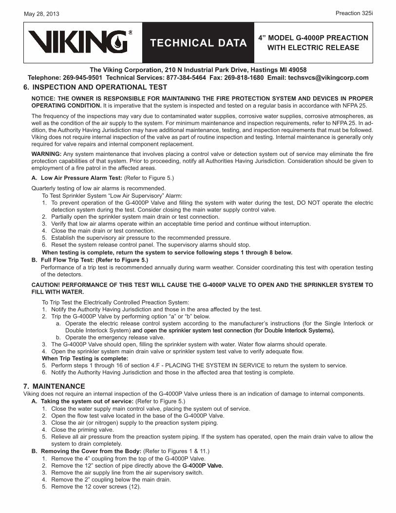
6. INsPECTIoN AND oPErATIoNAL TEsTNoTICE: THE owNEr Is rEsPoNsIBLE For MAINTAINING THE FIrE ProTECTIoN sysTEM AND DEVICEs IN ProPEr oPErATING CoNDITIoN. It is im�erative that the system is ins�ected and tested on a regular basis in accordance with NFPA 25.
The �requency o� the ins�ections may vary due to contaminated water su��lies, corrosive water su��lies, corrosive atmos�heres, as well as the condition o� the air su��ly to the system. For minimum maintenance and ins�ection requirements, re�er to NFPA 25. In ad-dition, the Authority Having Jurisdiction may have additional maintenance, testing, and ins�ection requirements that must be �ollowed. �iking does not require internal ins�ection o� the valve as �art o� routine ins�ection and testing. Internal maintenance is generally only required �or valve re�airs and internal com�onent re�lacement.
wArNING: Any system maintenance that involves �lacing a control valve or detection system out o� service may eliminate the �ire �rotection ca�abilities o� that system. Prior to �roceeding, noti�y all Authorities Having Jurisdiction. Consideration should be given to em�loyment o� a �ire �atrol in the a��ected areas.
A. Low Air Pressure Alarm Test: (Re�er to Figure 5.)
Quarterly testing o� low air alarms is recommended.To Test S�rinkler System “Low Air Su�ervisory” Alarm:1. To �revent o�eration o� the G-4000P �alve and �illing the system with water during the test, DO NOT o�erate the electric
detection system during the test. Consider closing the main water su��ly control valve.2. Partially o�en the s�rinkler system main drain or test connection.3. �eri�y that low air alarms o�erate within an acce�table time �eriod and continue without interru�tion.4. Close the main drain or test connection.5. Establish the su�ervisory air �ressure to the recommended �ressure.6. Reset the system release control �anel. The su�ervisory alarms should sto�.when testing is complete, return the system to service following steps 1 through 8 below.
B. Full Flow Trip Test: (refer to Figure 5.)Per�ormance o� a tri� test is recommended annually during warm weather. Consider coordinating this test with o�eration testing o� the detectors.
CAUTIoN! PErForMANCE oF THIs TEsT wILL CAUsE THE G-4000P VALVE To oPEN AND THE sPrINkLEr sysTEM To FILL wITH wATEr.
To Tri� Test the Electrically Controlled Preaction System:1. Noti�y the Authority Having Jurisdiction and those in the area a��ected by the test.2. Tri� the G-4000P �alve by �er�orming o�tion “a” or “b” below.
O�erate the electric release control system according to the manu�acturer’s instructions (�or the Single Interlock or Double Interlock System) and o�en the s�rinkler system test connection (�or Double Interlock Systems).and o�en the s�rinkler system test connection (�or Double Interlock Systems)..O�erate the emergency release valve.
3. The G-4000P �alve should o�en, �illing the s�rinkler system with water. Water �low alarms should o�erate.4. O�en the s�rinkler system main drain valve or s�rinkler system test valve to veri�y adequate �low.when Trip Testing is complete:5. Per�orm ste�s 1 through 16 o� section 4.F - PLACING THE SYSTEM IN SER�ICE to return the system to service.6. Noti�y the Authority Having Jurisdiction and those in the a��ected area that testing is com�lete.
7. MAINTENANCE�iking does not require an internal ins�ection o� the G-4000P �alve unless there is an indication o� damage to internal com�onents.
A. Taking the system out of service: (Re�er to Figure 5.)1. Close the water su��ly main control valve, �lacing the system out o� service.2. O�en the �low test valve located in the base o� the G-4000P �alve.3. Close the air (or nitrogen) su��ly to the �reaction system �i�ing.4. Close the �riming valve.5. Relieve all air �ressure �rom the �reaction system �i�ing. I� the system has o�erated, o�en the main drain valve to allow the
system to drain com�letely.B. removing the Cover from the Body: (Re�er to Figures 1 & 11.)
1. Remove the 4” cou�ling �rom the to� o� the G-4000P �alve.2. Remove the 12” section o� �i�e directly above the G-4000P �alve.G-4000P �alve. �alve.3. Remove the air su��ly line �rom the air su�ervisory switch.4. Remove the 2” cou�ling below the main drain.5. Remove the 12 cover screws (12).
a.
b.

TECHNICAL DATA
May 28, 2013
The Viking Corporation, 210 N Industrial Park Drive, Hastings MI 49058Telephone: 269-945-9501 Technical services: 877-384-5464 Fax: 269-818-1680 Email: [email protected]
Preaction 325j
4” MoDEL G-4000P PrEACTIoN wITH ELECTrIC rELEAsE
6. The cover and trim that is still connected may now be removed �rom the valve body. (It may be necessary to �ry the valve o�en as the dia�hragm may bond itsel� to the cover and body over time.)
C. removing / replacing the Check Diaphragm: (Re�er to Figure 11.)1. The check dia�hragm (10) may be li�ted �rom the valve body (1).2. I� necessary, re�lace the check dia�hragm (10).
D. Inspecting the Prime Chamber and Coupling for Leaks: (Re�er to Figure 5.)I� desired, it is �ossible to set the G-4000P �alve and ins�ect �or leaks with the cover removed.1. Slowly o�en the �rime valve.2. With �rime water established, �artially o�en the main water su��ly control valve.3. �isually ins�ect the inside o� the G-4000P �alve �or leaks. 4. Close the water su��ly control valve.
E. removing / replacing the Prime Coupling: (Re�er to Figure 11.)1. O�en the 1/2” union on the �rime line. 2. Using a wrench on the �lats o� the cou�ling (7), remove the cou�ling (7) �rom the valve body (1).3. Ins�ect the cou�ling (7) and O-rings (5 and 6). Re�lace i� necessary,, using the instructions in O-Ring Re�lacement Bulletin
F_120611.F. removing / replacing the Prime Chamber Assembly: (Re�er to Figure 11.)
1. The �rime chamber assembly (4) is now held in �lace by two �langes on the outside diameter o� the assembly. Slide the �rime chamber assembly (4) toward the �rime line and remove �rom the body (1).
2. Ins�ect and re�lace i� necessary. 3. Ins�ect the seat. The seat should be clean and �ree o� �oreign material. I� the seat is damaged, the G-4000P �alve must be
re�laced. G. re-Assembling the Valve: (Re�er to Figure 11.)
1. Place the �rime chamber assembly (4) in the valve body (1). Make sure the two �langes are �ositioned in the groove.2. Thread the �rime cou�ling (7) into the valve body (1). Make sure the end o� the �rime cou�ling (7) is inserted into the �rime
chamber assembly (4).3. Tighten the 1/4” socket set screw (8).4. Lay the check dia�hragm (10) into the valve body (1).5. Position the cover onto the valve body (1), and install and tighten the cover screws (12).6. Re-install any trim that was removed.7. Place the valve in service by �ollowing the ste�s in Section 4.F.
8. AVAILABILITyThe �iking Model G-4000P �alve is available through a network o� domestic and international distributors. See the �iking Cor�. Web site �or closest distributor or contact The �iking Cor�oration.
TECHNICAL DATA
May 28, 2013
4” MoDEL G-4000P PrEACTIoN wITH ELECTrIC rELEAsE
The Viking Corporation, 210 N Industrial Park Drive, Hastings MI 49058Telephone: 269-945-9501 Technical services: 877-384-5464 Fax: 269-818-1680 Email: [email protected]
Preaction 325k
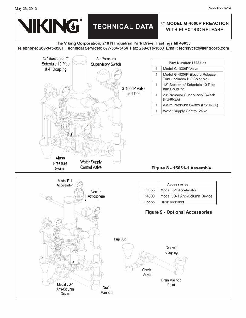
Figure 8 - 15651-1 Assembly
Part Number 15651-1:1 Model G-4000P �alve1 Model G-4000P Electric Release
Trim (Includes NC Solenoid)1 12” Section o� Schedule 10 Pi�e
and Cou�ling1 Air Pressure Su�ervisory Switch
(PS40-2A)1 Alarm Pressure Switch (PS10-2A)1 Water Su��ly Control �alve
Accessories:08055 Model E-1 Accelerator14800 Model LD-1 Anti-Column Device15588 Drain Mani�old
Figure 9 - optional Accessories
TECHNICAL DATA
May 28, 2013
The Viking Corporation, 210 N Industrial Park Drive, Hastings MI 49058Telephone: 269-945-9501 Technical services: 877-384-5464 Fax: 269-818-1680 Email: [email protected]
Preaction 325l
4” MoDEL G-4000P PrEACTIoN wITH ELECTrIC rELEAsE
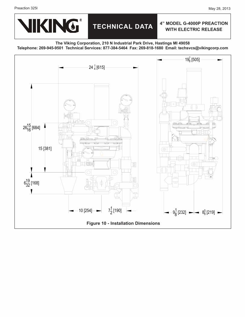
Figure 10 - Installation Dimensions
TECHNICAL DATA
May 28, 2013
4” MoDEL G-4000P PrEACTIoN wITH ELECTrIC rELEAsE
The Viking Corporation, 210 N Industrial Park Drive, Hastings MI 49058Telephone: 269-945-9501 Technical services: 877-384-5464 Fax: 269-818-1680 Email: [email protected]
Preaction 325m
Form No. F_111608 Revised �age re�laces �age 325a-m, dated Se�tember 2, 2010. (Revised �igure 11 and re�lacement �arts com�onents.)
23
4
5
5
6
7
8
9
1
Item Number
Part Number Description Material Number
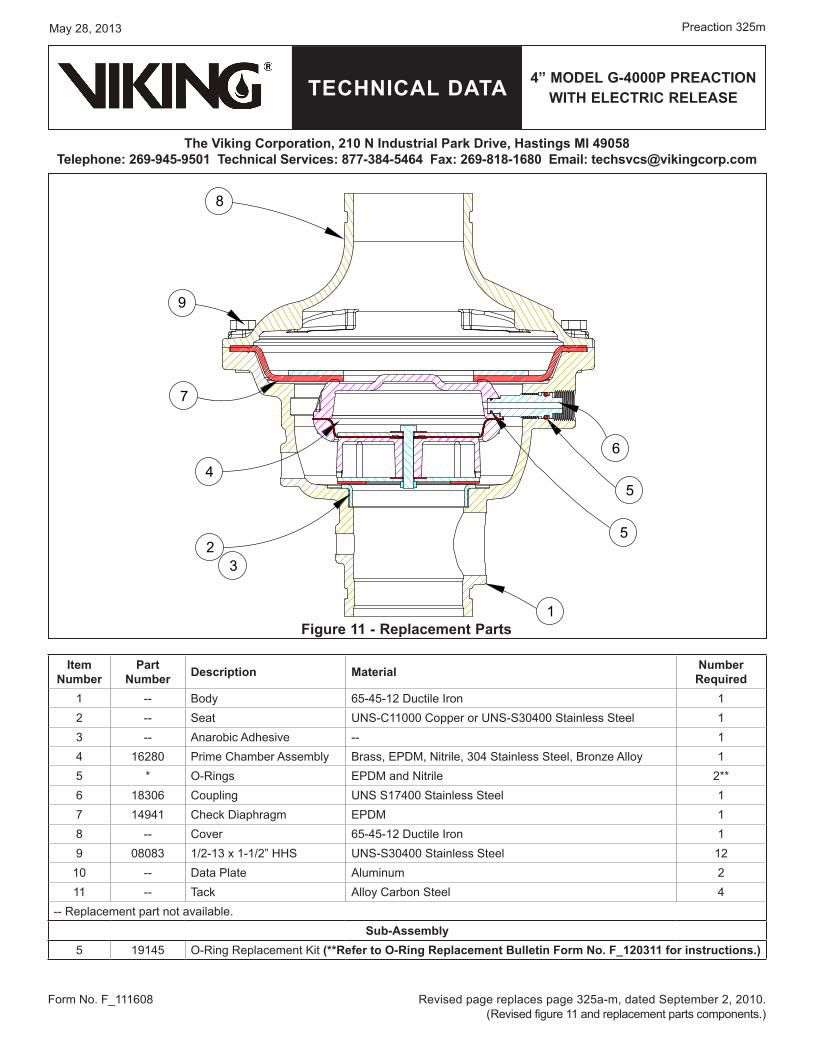
required1 -- Body 65-45-12 Ductile Iron 12 -- Seat UNS-C11000 Co��er or UNS-S30400 Stainless Steel 13 -- Anarobic Adhesive -- 14 16280 Prime Chamber Assembly Brass, EPDM, Nitrile, 304 Stainless Steel, Bronze Alloy 15 * O-Rings EPDM and Nitrile 2**6 18306 Cou�ling UNS S17400 Stainless Steel 17 14941 Check Dia�hragm EPDM 18 -- Cover 65-45-12 Ductile Iron 19 08083 1/2-13 x 1-1/2” HHS UNS-S30400 Stainless Steel 12
10 -- Data Plate Aluminum 211 -- Tack Alloy Carbon Steel 4
-- Re�lacement �art not available.sub-Assembly
5 19145 O-Ring Re�lacement Kit (**refer to o-ring replacement Bulletin Form No. F_120311 for instructions.)
Figure 11 - replacement Parts