i 08.12.05 instr oata sheets oap · ident no. 3-49-15207-000 serial no. 712230 manufacturer bopp...
TRANSCRIPT

INSTRUMENT Bopp & Reuther Messtechnik NIORDC Bopp & ReutherMesstechnlk"DATA SHEET Engineering GmbH Esfahan Oil Refining ENGINEERING ~Elec\ronik Component, Sensor lieferanll SUDPlier: Kunde I Customer:
Vacuum Bottom Oval Wheel Meter REP 20750 41070Projekt: Anfaoenteil: Kunden-AuftraaS-Nr .. 8&R-Auftraas-Nr ..
1. tdent,ficat,on
Descriotion Specification (unit I min I operation I max) RemarksTAG No. I KKS - No. FE 1021, FT 1021A FT 1021BP&I Diaoram No. and locationinstallation location Meter runbus addressmedium Vacuum boltom \main line size I pressure ratina I pipe class DN6" IPN IANSI300
I product type Oval Wheel MeterI product name (model code) OAP1200AG20M5/D2-F-R-S-L -30-75-1-4-1Ident No. 3-49-15207-000serial No. 712230manufacturer Bopp & Reuther2. Appiication
6. Performance characteristics
5 Ot
inputmeasured variablemeasurinq ranqe (min - norm max) IImin 500 3500 5000adjusted ranoeeffective rangebtockina distancesensor, type l :A.G20(2-channel) .••••
UIPU
output sianal (reauencyPulse frequency 1,6 pplCounter 5-digit mechanical counter, resetable
7. Operating conditions7.1 Installation conditions
Error limits % +1. 0,5 I o( valuerepeatability error % I o( span of soan or valueinfluence of medium oressure..
7.2 EnVironmentalconditions
installation instruction B 419.1start up conditionswarm UD time sintet run xD Not necessaryoutlet run xD Not necessarymax. cable lenoth memittino anale •
7.3 Process conditions
normal operatina (ambient) temperature 'C -10 +90storace temoerature 'C -20 +70immunity to temperature chanaeclimate class I air conditioned I I heated and/or cooled enclosed location
I sheltered location I I isolation cover I X I outdoorshock resistancevibration resistanceelectromaonetic comoatibiiitvinaress orotection IP 154 I NEMAI
I orocess temoerature 'C 200I process pressure bar 13density ka/m' 850viscosity cSt 15opera tina volume now m'/h 225 37501lmin)normal volume flow m'/h 175 291711min)limitlna process temperature 'C 250IimitinQ process pressure ranae bar 28Iimitina now m'/h 300
Rev. 0 Rev. , Rev. 2 I Rev. 3 Rev. 4 Rev. 5 Rev. 6 Rev. 7 Rev. 820.12.05OFIssue FileNo. Document No. I Client Document No. I~heet I ~f08.12.05 INSTR OATA SHEETS OAPBopp & Reuther Messtechnik Engineering GmbH- Am Neuen Rheinhafen 4, 67346 Speyer. Germany
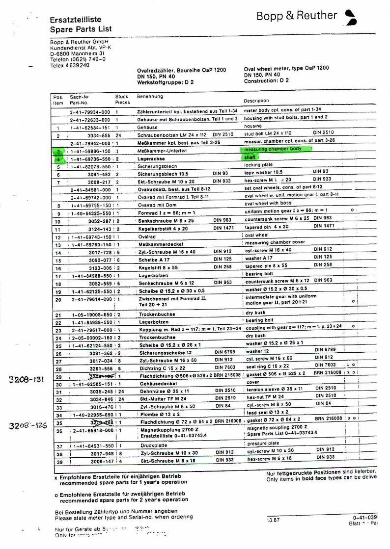
ErsatzteillisteSpare Parts List
Bopp 6. Reuther GmbHKundendlenst Abl. VP.K0-6800 Mannhelm 31Telelon 106211749-0Telex 4639240
O..,elradzahler. Baureihe OaP 1200ON150. PN 40WerkstoHgruppe: D 2
Bopp & Reuther
Oval wheel meter. type OaP 1200ON 150. PN 40Construction: 0 2
Pos. Sach.Nr SIUCk Benennung
Item Part-No Pieces Oescrlpllon
2-41-79934-000 1 Z~hl.rlJnterteil kpl. bestehend aus Teill.34 meter body cpl, cons. 01 part 1-34
2-41-72633-000 , Gehiiuse mit Schraubenbolun. Teil 1 und 2 housin9 with slud bolts. PlJrt 1 and 2
\ 1_41_62584_151 1 Gehause hOU$lng
2 3034-856 24 Schraubonbolzen LM 24 Jl 112 DIN 2510 ,Iud boll LM 24 .112 OlN2510
2-41-79942-000' 1 M.Okammer kp!. best. aus T,II 3.26 musur. cl'lamber cpl, cons, of pert 3.26
1c3~ ' 1-41-59886-150 .\ MeBkamm~r.Unlerteil ;P--mellUnng en amber bOd~
14""" 1-41-69736-550' 2 lag.rach •• h.oft,t5
, 1-41-82076-550: 1 : SlcherungsDlecn . locking plate
6 3091-492 2 Sicherungsbhtch to.5 DIN 93 tape washer 10.5 DIN 93
7 3008-217 2 6kt.-Schraube M '0 x 20 DIN 933 hu-scr.w M" , 20 DIN 933
2-4\-84581-000 1 O••••lr.dsalL beat. aUI hI! 8.12 set oyal wheels. can'. 01 part 8-12
2-41-69742-000 , Ovalrad mIl Formrad I. leil 8.11 oval wheel w. unil. mollon gear f. oarl 8-11
8 1-41-69755-1 SO; , OV81rad mil Dam oval wheel with boss
9 , 1-40-64325-550 I 1 Formrad I z - 86: m - 1 uniform molion ~ear 1z - sa: m - , o.
'0 1 3052-287 I 2 . S.nklchr.ube M6 z 25 DIN 963 countersunk Icrew M 6 II 25 DIN 963
" 3124-143 : 2 Keg.lkerb.tift 4 ll.20 DIN 1471 lapered pin 4 ll.20 DIN 1471
12 , 1-41-69743-150! 1 Ovaltad : oval wheel
'3 1-41-69760-150 I 1 M.Okammercleckel : menurin9 chamber coyer
,4 I 3017-728 i 6 . Zyl..$chraube M 16 • 40 OIN'it12 cyl .•screw M 16 •. oiO DIN 912
,5 , 3090-077 : 6 Sch.lbe A 17 OIN 125 ; wither A 17 DIN 125
'6 3123-006 : 2 . K'gelstltt 8 x 55 OIN 258 . u~ered ~in 8 •. 55 DIN 258
17 . 1-41-84988-550 11 Lagerbolun ! burlng bolt
'8, 3052-569 ! 6 Senkschr.ub. M 6 • 12 DIN 963 , countersunk screw M 6 •. 12 DIN 963
'9 ! 1-41-62125-550 I 2 : Sch,lb. 0 15.2 x 0 30 ;I 0,5 ; wuh., 0 15.2 ;I 0 30 I 0.5 , ,20 2-41-79614-000 : 1 Zwillehenr.d mn Formnld 11. : intermediate gear with uniform I
i " T.i! 20 + 21 ; motion gur II. part 20+21 . 01,2' 1-05-19008-650; 2 . T'oek.nbuehse ; dry bush
22 1-41 •.84989-550 i 1 l'V.rbolun ! bearing bolt
23 .2-41-79617-000; , KUDPlung m. RId z -117: m - 1. Tell 23+24 (;ou~ljng wllh gur z _117: m - t. p. 23+24 : 0
24 i 2-05-00002-160 I 2 . Trock.nbuch •• dry bush, ,
25 , 1-41-62124 •.550 I 2 Sch,lb. " 15,2 II 0 26 •. 1 wash., 0 15.2 II " 26 ll.1
26 3091-362 i :1 Slehe,ungneheib' 12 DIN 6799 wuh.r 12 CIN 6799 i
27 3017-034 , 8 Zyl..Sehraub. M 16 I 60 DIN 912 cyl. 5crew M 16 ): 60 DIN 912,
28 3261-666 . 8 Dic:;:htrl"g ~ ~6 JI 22 DIN 7603 lieal ring C 16 ll.22- DIN 7603 .. 0 ,29 , , 1 flachdichlung 0506." 529 J. 2 BRN 21600B ' gnk.t 0 506 ,1. " 529 I 2 BRN 216008 ! ll. 01
30 : 1-41-62585-151 .1 Gehiu •• deck,1 coyer : :
3' 3035-245 : 24 Oehnhi,;l •• " 35 x 11 DIN 2510 i ten,ion sleeve: e 3S 1I 11 DIN 2510 ; ,32 , 3034-845 i 24 6kt.-MuU,r TF M 24 DIN 2510 hu-nul TF M 24 DIN 2$10 ,
33 : 3016-476 i 1 Zyl..Schraube Me. 50 OIN 84 cyl..screw M 8 • 50 DIN 84,
34 , , -40 .•.22955-650 I 1 : Plombe 0 13 x 2 i lead .ul 0 13 ll.2 ; r35 3~h11 Flachdichtung 0 72 • 0 84 I 2 BRN 216008 , gukrt 0 72 • 0 84 x 2 BRN 216008 ! ll. 0'
36 i 2_41_65918_000 ! , : Magnelkupplung 2700 Z " m.gn.Uc coupling 2700 Z i I
! i ; Ersatztellli.l. 0-41-03743.4 : Spare Parts list 0_41_03743.4 j
37 ; 1_4'_84931_55011 Oruckptalte : pressure plale I I
38 i 3017-948 i 8 Zyl.•Schr.ube M 10 x 30 DIN 912 " eyl..,crew M 10 :r.30 DIN 912 ,
3QO!-147 : 4 hel.screw M 6 ;I 18 DIN 933,
39 I 6kt-Schr.ube M6 ,1. 18 DIN 933,
x Empfohlene Ersatzteile rur einjDhrigen Betriebrecommended spare perts for 1 year's operation
o Emptohlene Ersetzteile filr zweijahrigen Betrlebrecommended spare parts for 2 year's operation
Nut fettgedruckte Positlonen sind Ileferb.Bf.Only items In bold tace types can be dehve
Bel Bestellung Z~hler1YP und Nummer angcbenPlease state meIer type and Serial.no. when ordenng
!'Jur fUr Gefale ab s.~'"~.Onlv I:.' ~:""~ ,:",'" .
:0.87 0-4'-039Elatl .•• Pal
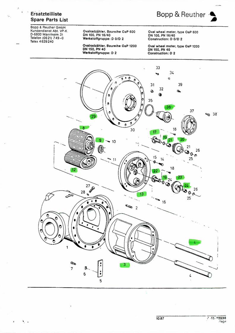
ErsatzteillisteSpare Parts List
Bopp & Reuther .~
Bopp & Reuther GmbHKundendienst Abt. VP.K0.6800 Mannheim 31Telefon (06211 749-0Telex 4639240
Ovalradzahler, Baurt=ihe OaP 600ON 100, PN 16/40Work.loHgruppo: 0 010 2
Oval wheel meter, type OaP 600ON 100, PN 16/40Constluction: 0 010 2
OVl!lradztihler. Baureihe OaP 1200ON 150, PN 40Work.loHgruppe: 0 2
Oval wheel meter, type OaP 1200ON 150, PN 40Con,tructlon: 0 2
33
"I;; 38
,--
37
39
Go.
34
32~
"'" 16
--.-------
31
".
"-~I.~' ng. "'"'- :2 LV..,;---.. @~'26
_ '. , G-f'II~ 14' 25~-
..•..
30
-.. 10
........•....:-- 11
-....
-......•.•...
~7
--III
I~2
-------20
28 I'"
5
10.87 " .~1.~~938.':tgf'
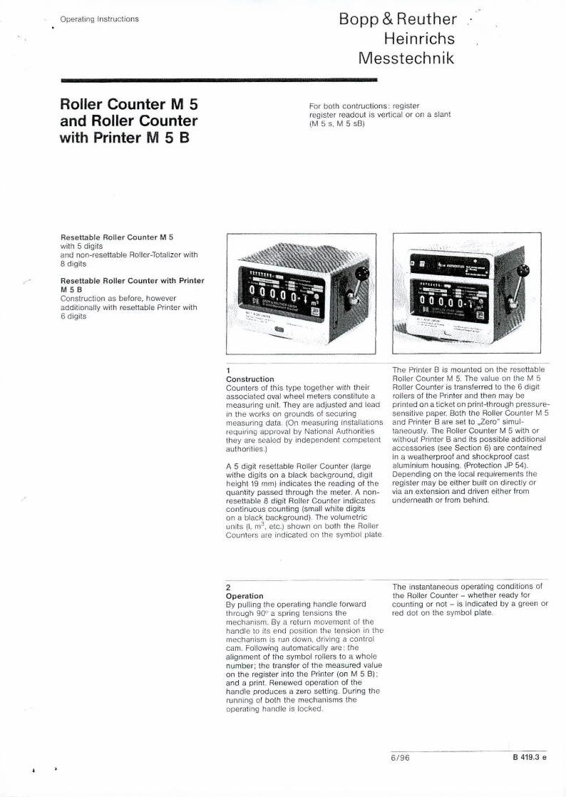
Operating Instructions
Roller Counter M 5and Roller Counterwith Printer M 5 B
Bopp & ReutherHeinrichs
Messtechnik
For both cant ructions : registerregister readout is vertical or on a slant(M 5 s. M 5 sB)
Reseltable Roller Counter M 5with 5 digitsand non-resettable Roller-Totalizer with8 digits
Resettable Roller Counter with PrinterMSBConstruction as before. howeveradditionally with reseUable Printer with6 digits
••--1ConstructionCounters of this type together with theirassociated oval wheel meters constitute ameasuring unit. They are adjusted and leadin the works on grounds of securingmeasuring data. (On measuring installationsrequiring approval by National Authoritiesthey are sealed by independent competentauthorities.)
A 5 digit reseUable Roller Counter (largewithe digits on a black background. digitheighl 19 mm) indicates the reading of theQuantity passed through the meter. A nOI1-reseltable 8 digit Roller Counter indicatescontinuous counting (small white digitson a black background). The volumetricunits (I, m3• elc.) shown on both the RollerCounters are indicated on the symbol plate
2OperationBy pulling the operating handle forwardthrough 900 a spring tensions themechanism. By a return movement of thehandle to its end position the tension in themechanism is run down, driving a controlcam. Following automatically are: thealignment of the symbol rollers to a wholenumber; the transfer of the measured valueon the register into the Printer (on M 5 B);and a print. Renewed operation of thehandle produces a zero setting. During therunning of both the mechanisms theoperating handle is locked.
• t.. •. ,..:::-----
••.•.•..•...._--
The Printer B is mounted on the resettableRoller Counter M 5. The value on the M 5Roller Counter is transferred to the 6 digitrollers of the Printer and then may beprinted on a ticket on print-through pressure-sensitive paper, Both the Roller Counter M 5and Printer B are set to ..leroft simul-taneously. The Aoller Counter M 5 with orwithout Printer B and its possible additionalaccessories (see Section 6) are containedin a weatherproof and shockproof castaluminium housing. (Protection Jp 54).Depending on the local requirements theregister may be either built on directly orvia an extension and driven either fromunderneath or from behind.
The instantaneous operating conditions ofthe Roller Counter - whether ready forcounting or not - is indicated by a green orred dot on the symbol plate.
6/96 B 419.3 e

Bopp & Reuther A~Messtedll1ik GrnhH _.-
The pulse pick-up AG 19 and AG 20 are employedto control electro-mechanical counters, read outdevices. recorders, regulators (preferably GaP),electronic counters, data processing equipment,as well as for remote counters for printing enginesusing step motors. AG 20 is approved for use inoval wheel counters for fiscal metering purposes.Pulse pick-up serie AG 19 may only be used forinternal metering purposes (No. of approval AG19: 411.007;AG 20: 411.005).
1/2110/20132350/min187 Hz depending on counter design-2510 + 90"CIP 54 (DIN 40 050)IP 67 (DIN 40 050)DMT 99 ATEX 2219 xII 2G EEx ia IIC T6in compliance with EN 50227 (NAMUR) and Ex-approvalup to a maximum of 50 Ohm/wireAG 19: 2 wire, shieldedAG 20: 4 wire. twisted in pairsPg 13.5
connection of external devices
control cable
cable conneclions
Technical Datanumber of control 5;Ot5max. revolutions per minutemax. puls€ frequencyambient temperalurehousing protection typecontrol head protection typeEx-protection
Pulse Pick-up AG 19 and AG 20Inductive Pulse Pick-upSeries AG 19 and 20 in compliance with EN 50227 (NAMUR) for use as extensionfor all oval wheel meters ai, OaP and OM with mechanical signal transmission.
l'\'l>o-
Connection of terminals for models AG 19 and AG 20AG 20
:5fiI41]167';- ••••• 1 •••••.•••••••••••••••••
, •. 1,-"';', .•••••. , ••••••••••
~t~l--,+:- '+,uI ~I,,,1~!::J o~:::JI 01:0' .0 :01..0', I I III I
AG 190
151~!4i3!617. !I, , 'I' , ,..... ,..;,. , ' 1'
I" - , !,- ;+1- !+I-+i c: I C' -<ll :s: QJ! :s:.3 0 :J' 0.q .0 :0,: ..0'., ,II I
For seriesAG 19/20R: I: leading channel, II: reference channel, Ill: feedback channel
Subject 10 technical change 05.02 L 401.7.001eBopp & ReutherMesstechnik GmbHPoslfach 170967327 Speyer, GermanyAm Neuen Rhelnhafen 467346 Speyer, GermanyPhone' +49 (6232)657-0Fax: +49 (6232) 657-505
InterneteMail
•

General Data on Regulation for B & R Oval Wheel Meters
The Type of regulation set depends on the type of Oval Wheel Meter. It is pos-sible to modify a meter in such a way that the regulation may be exchangedexternally. This change however must be carried out in Bopp & Reuther...•orks.
There are basically 4 Types of regulation sets:
A. The 0.1 ".'" I 0.9 "III regulation (fine.'coarse steps, exchanged externally)for the series OaP.
B. The 0.2°.'" regulation for the series OaP, 01, OM and OT.
C. The 0.1 "':" regulation for the small Oval Wheel Meters Type OaP 06and OaP 1.
D. The 0.5 "i" regulation for the small meter type OP R7.
A. The 0,1 % /0,9% Regulation (External Regulation)
The 0.1 "I" 10.9 °/" regulation may have its regulation wheels exchanged exter-nally, without the necessity to remove any other built-on parts. For thisreason, the regulation is known as "external regulation". In general this typeof regulation is used only on larger melers with ticket printer, or by specialrequest.
,"
•
Fig 40.1 O.'D ; 0.9 I,'. Regulation device (external-regulation).
Left: View of side adjacent to the register.1 Ring housing of regulation device.2 Lockable cover to rC'guJ~~IO:1 doC", Ice.3 Dog Coupling (register side)
6
Right: View of side adjacent to the meter.4 Dog Coupling with dr;ve gear(meter side).