hyspeed ht2000lhf - hypertherm
TRANSCRIPT

Plasma ArcCutting System
Instruction Manual803020 – Revision 11
HySpeed ®
HT2000LHF ®
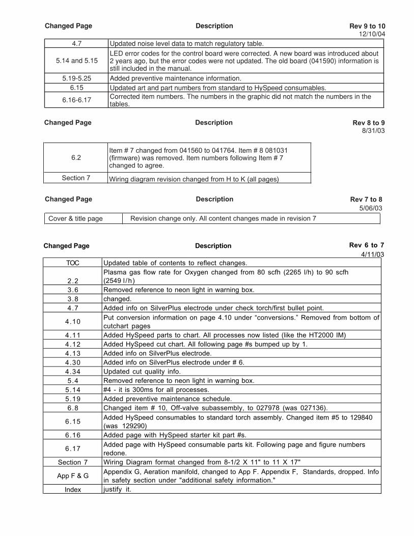
Changed Page Description Rev 7 to 8 5/06/03
Cover & title page Revision change only. All content changes made in revision 7
Changed Page Description Rev 6 to 74/11/03
TOC Updated table of contents to reflect changes.
2.2Plasma gas flow rate for Oxygen changed from 80 scfh (2265 l/h) to 90 scfh (2549 l /h )
3.6 Removed reference to neon light in warning box.3.8 changed.4.7 Added info on SilverPlus electrode under check torch/first bullet point.
4.10Put conversion information on page 4.10 under “conversions.” Removed from bottom of cutchart pages
4.11 Added HySpeed parts to chart. All processes now listed (like the HT2000 IM)4.12 Added HySpeed cut chart. All following page #s bumped up by 1.4.13 Added info on SilverPlus electrode.4.30 Added info on SilverPlus electrode under # 6.4.34 Updated cut quality info.5.4 Removed reference to neon light in warning box.
5.14 #4 - it is 300ms for all processes.5.19 Added preventive maintenance schedule.6.8 Changed item # 10, Off-valve subassembly, to 027978 (was 027136).
6.15Added HySpeed consumables to standard torch assembly. Changed item #5 to 129840 (was 129290)
6.16 Added page with HySpeed starter kit part #s.
6.17Added page with HySpeed consumable parts kit. Following page and figure numbers redone.
Section 7 Wiring Diagram format changed from 8-1/2 X 11" to 11 X 17"
App F & GAppendix G, Aeration manifold, changed to App F. Appendix F, Standards, dropped. Info in safety section under "additional safety information."
Index justify it.
Changed Page Description Rev 8 to 98/31/03
6.2Item # 7 changed from 041560 to 041764. Item # 8 081031 (firmware) was removed. Item numbers following Item # 7 changed to agree.
Section 7 Wiring diagram revision changed from H to K (all pages)
Changed Page Description Rev 9 to 1012/10/04
4.7 Updated noise level data to match regulatory table.
5.14 and 5.15LED error codes for the control board were corrected. A new board was introduced about 2 years ago, but the error codes were not updated. The old board (041590) information is still included in the manual.
5.19-5.25 Added preventive maintenance information.6.15 Updated art and part numbers from standard to HySpeed consumables.
6.16-6.17 Corrected item numbers. The numbers in the graphic did not match the numbers in the tables.
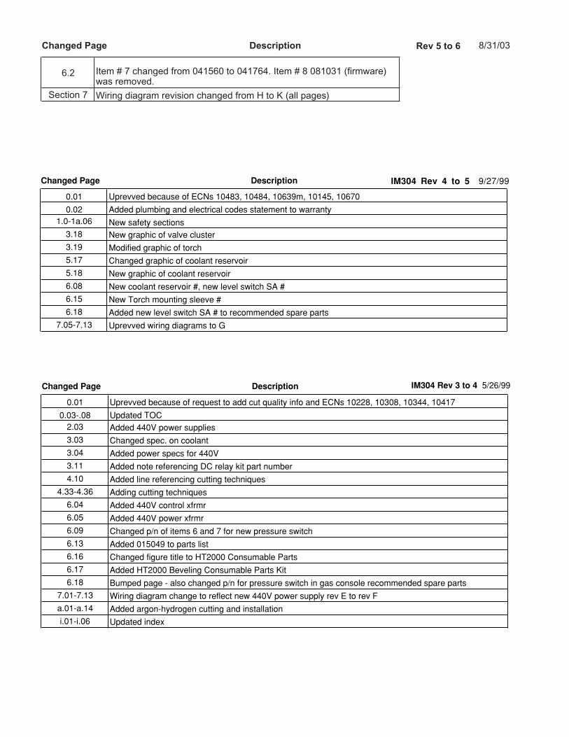
Changed Page Description IM304 Rev 3 to 4 5/26/99
0.01 Uprevved because of request to add cut quality info and ECNs 10228, 10308, 10344, 10417
0.03-.08 Updated TOC2.03 Added 440V power supplies
3.03 Changed spec. on coolant
3.04 Added power specs for 440V
3.11 Added note referencing DC relay kit part number
4.10 Added line referencing cutting techniques
4.33-4.36 Adding cutting techniques
6.04 Added 440V control xfrmr
6.05 Added 440V power xfrmr
6.09 Changed p/n of items 6 and 7 for new pressure switch
6.13 Added 015049 to parts list
6.16 Changed figure title to HT2000 Consumable Parts
6.17 Added HT2000 Beveling Consumable Parts Kit
6.18 Bumped page - also changed p/n for pressure switch in gas console recommended spare parts
7.01-7.13 Wiring diagram change to reflect new 440V power supply rev E to rev F
a.01-a.14 Added argon-hydrogen cutting and installation
i.01-i.06 Updated index
Changed Page Description IM304 Rev 4 to 5 9/27/99
0.01 Uprevved because of ECNs 10483, 10484, 10639m, 10145, 10670
0.02 Added plumbing and electrical codes statement to warranty1.0-1a.06 New safety sections
3.18 New graphic of valve cluster
3.19 Modified graphic of torch
5.17 Changed graphic of coolant reservoir
5.18 New graphic of coolant reservoir
6.08 New coolant reservoir #, new level switch SA #
6.15 New Torch mounting sleeve #
6.18 Added new level switch SA # to recommended spare parts
7.05-7.13 Uprevved wiring diagrams to G
Changed Page Description Rev 5 to 6 8/31/03
6.2 Item # 7 changed from 041560 to 041764. Item # 8 081031 (firmware) was removed.
Section 7 Wiring diagram revision changed from H to K (all pages)

Changed Page Description IM304 Rev 0 to 1 7/24/98
0.01 Uprevved because of ECNs 9523, 9483, grounding appendix, serial # jump to 2LHF-000150
0.07 Added System Grounding to TOC0.08 Added System Grounding to TOC
3.03 Referenced new grounding appendix
4.15 Added a sentence to Mild Steel 100A cutting cut chart
4.16 Added a sentence to Mild Steel 100A cutting cut chart
5.05 New power distribution PCB graphic, added fuse
5.14 Added error code for phase loss
6.02 New firmware rev
6.06 New graphic of chopper with phase loss board, new phase loss board #
6.16 Changed some quantities in consumable parts kit
7.01 Uprevved wiring diagrams to E
i.02 Added j1 to grounding requirements in index
i.04 Added phase loss to index
j.01 New system grounding appendix
j.02 New system grounding appendix
j.03 New system grounding appendix
j.04 New system grounding appendix
j.05 New system grounding appendix
Changed Page Description IM304 Rev 1 to 2 8/21/98
0.01 Uprevved because of ECNs 9763, 9758, 9803
0.08 Added figure of coolant flow diagram to TOC3.08 New graphic of rear panel
5.17 Added figure of coolant flow diagram
6.08 New graphic of rear panel, new p/ns for valve assembly, water pump assembly
7.04 Added coolant flow diagram to wiring diagrams
Changed Page Description IM304 Rev 2 to 3 1/18/99
0.01 Uprevved because of ECNs 10078, 10079, 10070, 9753, 10012, 9864, 10020, 9926
0.06 Changed TOC to reference HT2000LHF Torches0.08 Changed TOC to reference HT2000LHF Torches2.01 Added line in spec description to specify recommended production cutting thickness
2.02 Added note to Water Muffler description stating that it cannot be used with the stainless torch
2.03 Added dimension on torch diameter and referenced an additional drawing in Section 6
2.06 Added note to Water Muffler description stating that it cannot be used with the stainless torch
3.07 Added note to Water Muffler description stating that it cannot be used with the stainless torch
3.11 Updated signal labels for I/O cable
3.13 Added note to Water Muffler cable stating that it cannot be used with the stainless torch
4.11 Changed index to cut chart and consumables to include new electrode and swirl ring
4.12-4.29 Updated cut charts with new electrode, swirl ring, and clearer cutting capacities
5.02 Removed old style pump clamp from drawing
6.05 New part number for valve SV7
6.08 Added kits for pump and motor replacement
6.09 New part number for valves SV1-3
6.15 Added new stainless steel torch
6.16 Added new electrode to parts kit
6.17 New part numbers for valves, pump

HySpeed HT2000LHF
Instruction Manual
(P/N 803020)
Revision 11 – November, 2013
© Copyright 2013 Hypertherm, Inc.All Rights Reserved
Hypertherm, HT, LongLife, and HySpeed are trademarks of Hypertherm, Inc.and may be registered in the United States and/or other countries
Hypertherm, Inc.Hanover, NH USA
www.hypertherm.com

11/30/04
Hypertherm, Inc.
Etna Road, P.O. Box 5010Hanover, NH 03755 USA603-643-3441 Tel (Main Office)603-643-5352 Fax (All Departments)[email protected] (Main Office Email)800-643-9878 Tel (Technical Service)[email protected] (Technical Service Email)800-737-2978 Tel (Customer Service)[email protected] (Customer Service Email)
Hypertherm Automation, LLC
5 Technology Drive, Suite 300West Lebanon, NH 03755 USA603-298-7970 Tel 603-298-7977 Fax
Hypertherm Plasmatechnik, GmbH
Technologiepark HanauRodenbacher Chaussee 6 D-63457 Hanau-Wolfgang, Deutschland49 6181 58 2100 Tel49 6181 58 2134 Fax49 6181 58 2123 (Technical Service)
Hypertherm (S) Pte Ltd.
No. 19 Kaki Bukit Road 2 K.B. Warehouse Complex Singapore 417847, Republic of Singapore65 6 841 2489 Tel65 6 841 2490 Fax 65 6 841 2489 (Technical Service)
Hypertherm (Shanghai) Consulting Co., Ltd.
Suite 305, CIMIC Towers1090 Century Boulevard, PudongShanghai 200120P.R. China86-21-5835-5362 /3 Tel86-21-5835 5220 Fax86-21-5835-5362 /3 (Technical Service)
Hypertherm
Branch of Hypertherm, UK, UCPO Box 244Wigan, Lancashire, England WN8 7WU00 800 3324 9737 Tel00 800 4973 7329 Fax00 800 4973 7843 (Technical Service)
France
15 Impasse des Rosiers95610 Eragny, France00 800 3324 9737 Tel00 800 4973 7329 Fax
Hypertherm S.r.l.
Via Torino 220123 Milano, Italia39 02 725 46 312 Tel 39 02 725 46 400 Fax39 02 725 46 314 (Technical Service)
Hypertherm Europe B.V.
Vaartveld 94704 SE Roosendaal, Nederland31 165 596907 Tel 31 165 596901 Fax31 165 596908 Tel (Marketing)31 165 596900 Tel (Technical Service)00 800 49 73 7843 Tel (Technical Service)
Japan
1952-14 Yata-NatsumegiMishima City, Shizuoka Pref.411-0801 Japan81 0 559 75 7387 Tel81 0 559 75 7376 Fax
HYPERTHERM BRASIL LTDA.
Rua Jati, 33CEP 07180-350 CumbicaGuarulhos, SP - Brasil55 11 6482 1087 Tel55 11 6482 0591 Fax
ELECTROMAGNETIC COMPATIBILITY (EMC)
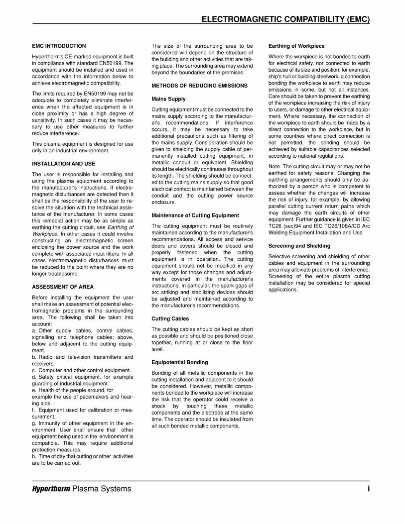
EMC INTRODUCTION
Hypertherm's CE-marked equipment is builtin compliance with standard EN50199. Theequipment should be installed and used inaccordance with the information below toachieve electromagnetic compatibility.
The limits required by EN50199 may not beadequate to completely eliminate interfer-ence when the affected equipment is inclose proximity or has a high degree ofsensitivity. In such cases it may be neces-sary to use other measures to furtherreduce interference.
This plasma equipment is designed for useonly in an industrial environment.
INSTALLATION AND USE
The user is responsible for installing andusing the plasma equipment according tothe manufacturer's instructions. If electro-magnetic disturbances are detected then itshall be the responsibility of the user to re-solve the situation with the technical assis-tance of the manufacturer. In some casesthis remedial action may be as simple asearthing the cutting circuit, see Earthing ofWorkpiece. In other cases it could involveconstructing an electromagnetic screenenclosing the power source and the workcomplete with associated input filters. In allcases electromagnetic disturbances mustbe reduced to the point where they are nolonger troublesome.
ASSESSMENT OF AREA
Before installing the equipment the usershall make an assessment of potential elec-tromagnetic problems in the surroundingarea. The following shall be taken intoaccount:a. Other supply cables, control cables,signalling and telephone cables; above,below and adjacent to the cutting equip-ment.b. Radio and television transmitters andreceivers.c. Computer and other control equipment.d. Safety critical equipment, for exampleguarding of industrial equipment.e. Health of the people around, for example the use of pacemakers and hear-ing aids.f. Equipment used for calibration or mea-surement.g. Immunity of other equipment in the en-vironment. User shall ensure that otherequipment being used in the environment iscompatible. This may require additionalprotection measures.h. Time of day that cutting or other activitiesare to be carried out.
Earthing of Workpiece
Where the workpiece is not bonded to earthfor electrical safety, nor connected to earthbecause of its size and position, for example,ship's hull or building steelwork, a connectionbonding the workpiece to earth may reduceemissions in some, but not all instances.Care should be taken to prevent the earthingof the workpiece increasing the risk of injuryto users, or damage to other electrical equip-ment. Where necessary, the connection ofthe workpiece to earth should be made by adirect connection to the workpiece, but insome countries where direct connection isnot permitted, the bonding should beachieved by suitable capacitances selectedaccording to national regulations.
Note. The cutting circuit may or may not beearthed for safety reasons. Changing theearthing arrangements should only be au-thorized by a person who is competent toassess whether the changes will increasethe risk of injury, for example, by allowingparallel cutting current return paths whichmay damage the earth circuits of otherequipment. Further guidance is given in IECTC26 (sec)94 and IEC TC26/108A/CD ArcWelding Equipment Installation and Use.
Screening and Shielding
Selective screening and shielding of othercables and equipment in the surroundingarea may alleviate problems of interference.Screening of the entire plasma cuttinginstallation may be considered for specialapplications.
The size of the surrounding area to beconsidered will depend on the structure ofthe building and other activities that are tak-ing place. The surrounding area may extendbeyond the boundaries of the premises.
METHODS OF REDUCING EMISSIONS
Mains Supply
Cutting equipment must be connected to themains supply according to the manufactur-er's recommendations. If interferenceoccurs, it may be necessary to takeadditional precautions such as filtering ofthe mains supply. Consideration should begiven to shielding the supply cable of per-manently installed cutting equipment, inmetallic conduit or equivalent. Shieldingshould be electrically continuous throughoutits length. The shielding should be connect-ed to the cutting mains supply so that goodelectrical contact is maintained between theconduit and the cutting power sourceenclosure.
Maintenance of Cutting Equipment
The cutting equipment must be routinelymaintained according to the manufacturer'srecommendations. All access and servicedoors and covers should be closed andproperly fastened when the cuttingequipment is in operation. The cuttingequipment should not be modified in anyway except for those changes and adjust-ments covered in the manufacturer'sinstructions. In particular, the spark gaps ofarc striking and stabilizing devices shouldbe adjusted and maintained according tothe manufacturer's recommendations.
Cutting Cables
The cutting cables should be kept as shortas possible and should be positioned closetogether, running at or close to the floorlevel.
Equipotential Bonding
Bonding of all metallic components in thecutting installation and adjacent to it shouldbe considered. However, metallic compo-nents bonded to the workpiece will increasethe risk that the operator could receive ashock by touching these metalliccomponents and the electrode at the sametime. The operator should be insulated fromall such bonded metallic components.
Hypertherm Plasma Systems i
WARRANTY
ii Hypertherm Plasma Systems9-01
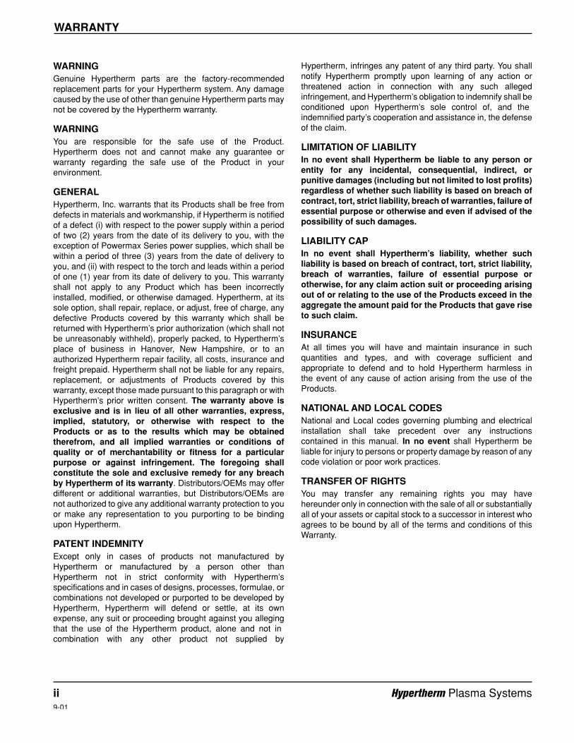
WARNINGGenuine Hypertherm parts are the factory-recommendedreplacement parts for your Hypertherm system. Any damagecaused by the use of other than genuine Hypertherm parts maynot be covered by the Hypertherm warranty.
WARNINGYou are responsible for the safe use of the Product.Hypertherm does not and cannot make any guarantee orwarranty regarding the safe use of the Product in yourenvironment.
GENERALHypertherm, Inc. warrants that its Products shall be free fromdefects in materials and workmanship, if Hypertherm is notifiedof a defect (i) with respect to the power supply within a periodof two (2) years from the date of its delivery to you, with theexception of Powermax Series power supplies, which shall bewithin a period of three (3) years from the date of delivery toyou, and (ii) with respect to the torch and leads within a periodof one (1) year from its date of delivery to you. This warrantyshall not apply to any Product which has been incorrectlyinstalled, modified, or otherwise damaged. Hypertherm, at itssole option, shall repair, replace, or adjust, free of charge, anydefective Products covered by this warranty which shall bereturned with Hypertherm’s prior authorization (which shall notbe unreasonably withheld), properly packed, to Hypertherm’splace of business in Hanover, New Hampshire, or to anauthorized Hypertherm repair facility, all costs, insurance andfreight prepaid. Hypertherm shall not be liable for any repairs,replacement, or adjustments of Products covered by thiswarranty, except those made pursuant to this paragraph or withHypertherm’s prior written consent. The warranty above isexclusive and is in lieu of all other warranties, express,implied, statutory, or otherwise with respect to theProducts or as to the results which may be obtainedtherefrom, and all implied warranties or conditions ofquality or of merchantability or fitness for a particularpurpose or against infringement. The foregoing shallconstitute the sole and exclusive remedy for any breachby Hypertherm of its warranty. Distributors/OEMs may offerdifferent or additional warranties, but Distributors/OEMs arenot authorized to give any additional warranty protection to youor make any representation to you purporting to be bindingupon Hypertherm.
PATENT INDEMNITYExcept only in cases of products not manufactured byHypertherm or manufactured by a person other thanHypertherm not in strict conformity with Hypertherm’sspecifications and in cases of designs, processes, formulae, orcombinations not developed or purported to be developed byHypertherm, Hypertherm will defend or settle, at its ownexpense, any suit or proceeding brought against you allegingthat the use of the Hypertherm product, alone and not incombination with any other product not supplied by
Hypertherm, infringes any patent of any third party. You shallnotify Hypertherm promptly upon learning of any action orthreatened action in connection with any such allegedinfringement, and Hypertherm’s obligation to indemnify shall beconditioned upon Hypertherm’s sole control of, and theindemnified party’s cooperation and assistance in, the defenseof the claim.
LIMITATION OF LIABILITYIn no event shall Hypertherm be liable to any person orentity for any incidental, consequential, indirect, orpunitive damages (including but not limited to lost profits)regardless of whether such liability is based on breach ofcontract, tort, strict liability, breach of warranties, failure ofessential purpose or otherwise and even if advised of thepossibility of such damages.
LIABILITY CAPIn no event shall Hypertherm’s liability, whether suchliability is based on breach of contract, tort, strict liability,breach of warranties, failure of essential purpose orotherwise, for any claim action suit or proceeding arisingout of or relating to the use of the Products exceed in theaggregate the amount paid for the Products that gave riseto such claim.
INSURANCEAt all times you will have and maintain insurance in suchquantities and types, and with coverage sufficient andappropriate to defend and to hold Hypertherm harmless in the event of any cause of action arising from the use of theProducts.
NATIONAL AND LOCAL CODESNational and Local codes governing plumbing and electricalinstallation shall take precedent over any instructionscontained in this manual. In no event shall Hypertherm beliable for injury to persons or property damage by reason of anycode violation or poor work practices.
TRANSFER OF RIGHTSYou may transfer any remaining rights you may havehereunder only in connection with the sale of all or substantiallyall of your assets or capital stock to a successor in interest whoagrees to be bound by all of the terms and conditions of thisWarranty.
TABLE OF CONTENTS
HySpeed HT2000LHF Instruction Manual iii7
Electromagnetic Compatibility (EMC).......................................................................................................................iWarranty .....................................................................................................................................................................ii
Section 1 SAFETYRecognize Safety Information...................................................................................................................................1-2Follow Safety Instructions.........................................................................................................................................1-2Cutting Can Cause Fire or Explosion .......................................................................................................................1-2Electric Shock Can Kill..............................................................................................................................................1-3Cutting Can Produce Toxic Fumes...........................................................................................................................1-3A Plasma Arc Can Cause Injury and Burns..............................................................................................................1-4Arc Rays Can Burn Eyes and Skin ...........................................................................................................................1-4Grounding Safety......................................................................................................................................................1-4Compressed Gas Equipment Safety ........................................................................................................................1-5Gas Cylinders Can Explode If Damaged ..................................................................................................................1-5Noise Can Damage Hearing.....................................................................................................................................1-5Pacemaker and Hearing Aid Operation ....................................................................................................................1-5A Plasma Arc Can Damage Frozen Pipes................................................................................................................1-5Additional Safety Information....................................................................................................................................1-5Warning Label...........................................................................................................................................................1-6
Section 1a SÉCURITÉIdentifier les consignes de sécurité.........................................................................................................................1a-2Suivre les instructions de sécurité ..........................................................................................................................1a-2Le coupage peut provoquer un incendie ou une explosion ....................................................................................1a-2Les chocs électriques peuvent être fatals...............................................................................................................1a-3Le coupage peut produire des vapeurs toxiques....................................................................................................1a-3L'arc plasma peut provoquer des blessures ou des brûlures .................................................................................1a-4Mise à la masse et à la terre...................................................................................................................................1a-4Les rayons de l'arc peuvent brûler les yeux et la peau...........................................................................................1a-4Sécurité des bouteilles de gaz comprimé ...............................................................................................................1a-5Les bouteilles de gaz comprimé peuvent exploser en cas de dommages .............................................................1a-5Le bruit peut provoquer des problèmes auditifs......................................................................................................1a-5Pacemakers et prothéses auditives........................................................................................................................1a-5Étiquette de sécurité ...............................................................................................................................................1a-6
Section 2 SPECIFICATIONSHySpeed HT2000LHF System Components ............................................................................................................2-1
Power Supply ..................................................................................................................................................2-1HySpeed LHF Machine Torch..........................................................................................................................2-1Gas Console ....................................................................................................................................................2-1Argon-Hydrogen Manifold – Optional...............................................................................................................2-1Digital Remote Voltage & Current Control Console .........................................................................................2-1Programmable Remote Voltage & Current Control Console............................................................................2-1Remote Current Control Console.....................................................................................................................2-2Initial Height Sensing - Optional.......................................................................................................................2-2Timer/Counter – Optional.................................................................................................................................2-2
TABLE OF CONTENTS
iv HySpeed HT2000LHF Instruction Manual7
Water Muffler – Optional ..................................................................................................................................2-2CommandTHC – Optional................................................................................................................................2-2
Specifications............................................................................................................................................................2-2System Requirements .....................................................................................................................................2-2Power Supply ...................................................................................................................................................2-3HySpeed LHF Machine Torch..........................................................................................................................2-3Gas Console ....................................................................................................................................................2-4Argon-Hydrogen Manifold – Optional...............................................................................................................2-4Digital Remote Voltage & Current Control Console .........................................................................................2-5Programmable Remote Voltage & Current Control Console............................................................................2-5Remote Current Control Console.....................................................................................................................2-5Initial Height Sensing (IHS) – Optional.............................................................................................................2-6Timer/Counter – Optional.................................................................................................................................2-6Water Muffler – Optional ..................................................................................................................................2-6CommandTHC – Optional................................................................................................................................2-6
Section 3 INSTALLATIONUpon Receipt ............................................................................................................................................................3-1Claims.......................................................................................................................................................................3-1Installation Requirements .........................................................................................................................................3-1Gas Requirements....................................................................................................................................................3-1
Gas Supply Plumbing.......................................................................................................................................3-2Torch Coolant Requirements....................................................................................................................................3-3Grounding Requirements..........................................................................................................................................3-3Noise Levels .............................................................................................................................................................3-4Power Requirements ................................................................................................................................................3-4
Line Disconnect Switch ....................................................................................................................................3-4Power Cable.....................................................................................................................................................3-5Positioning the Power Supply ..........................................................................................................................3-5
Connecting the Power ..............................................................................................................................................3-5Torch Lifter Requirement ..........................................................................................................................................3-7Optional Equipment ..................................................................................................................................................3-7
Water Muffler....................................................................................................................................................3-7System Units Placement...........................................................................................................................................3-7Power Supply Connections.....................................................................................................................................3-10Gas Console Connections ......................................................................................................................................3-14Valve Cluster and Torch Connections ....................................................................................................................3-17
Routing the Torch Leads................................................................................................................................3-17Connecting the Torch Leads to the Torch......................................................................................................3-17Valve Cluster Connections.............................................................................................................................3-18
Mounting the Machine Torch ..................................................................................................................................3-20Torch Alignment .............................................................................................................................................3-20
Section 4 OPERATIONFront Panel Controls and Indicators .........................................................................................................................4-1
Status Indicators Before Startup ......................................................................................................................4-1
TABLE OF CONTENTS
HySpeed HT2000LHF Instruction Manual v7
Power Supply ...................................................................................................................................................4-1Gas Console ....................................................................................................................................................4-2Digital Remote Voltage & Current Control Console .........................................................................................4-3Programmable Remote Voltage & Current Control Console............................................................................4-3Remote Current Control Console.....................................................................................................................4-3Timer/Counter ..................................................................................................................................................4-4
System Checkout......................................................................................................................................................4-4Set Switches and Check Torch ........................................................................................................................4-4Turn Gases On.................................................................................................................................................4-4Turn Power Supply On and Adjust Voltage/Current.........................................................................................4-5Adjust Preflow Gases.......................................................................................................................................4-5Adjust Cut Flow Gases and Check Initial Height Sensing (IHS) ......................................................................4-5Final Torch Adjustment ....................................................................................................................................4-6
Check Torch Height Control (THC) and Digital Remote Voltage & Current Console ...............................................4-6Noise Levels .............................................................................................................................................................4-7Daily Startup .............................................................................................................................................................4-7
Check Torch.....................................................................................................................................................4-7Turn Gases On.................................................................................................................................................4-8Turn Power Supply On and Adjust Voltage & Current .....................................................................................4-8Adjust Preflow Gases.......................................................................................................................................4-8Adjust Cut Flow Gases and Prepare for Cutting ..............................................................................................4-9
Common Cutting Faults ............................................................................................................................................4-9Technical Questions ...............................................................................................................................................4-10Cut Charts...............................................................................................................................................................4-10Conversions............................................................................................................................................................4-10Cut Chart and Consumable Parts Index .................................................................................................................4-11Changing Consumable Parts..................................................................................................................................4-31
Removal and Inspection.................................................................................................................................4-31Replacement ..................................................................................................................................................4-32Changing the Water Tube ..............................................................................................................................4-33
How to Optimize Cut Quality...................................................................................................................................4-34Tips for Table and Torch ................................................................................................................................4-34Plasma Set-up Tips........................................................................................................................................4-34Maximize the Life of Consumable Parts.........................................................................................................4-34Additional Factors of Cut Quality....................................................................................................................4-35Additional Improvements................................................................................................................................4-36
Section 5 MAINTENANCEIntroduction ...............................................................................................................................................................5-1Routine Maintenance................................................................................................................................................5-1
Torch and Torch Leads ....................................................................................................................................5-1Power Supply ...................................................................................................................................................5-2Gas Console ....................................................................................................................................................5-3
Start Sequence .........................................................................................................................................................5-3Initial Checks ............................................................................................................................................................5-4Troubleshooting ........................................................................................................................................................5-6
TABLE OF CONTENTS
vi HySpeed HT2000LHF Instruction Manual10
Status Led Troubleshooting......................................................................................................................................5-9Chopper Module Test Procedure............................................................................................................................5-12Error Codes ............................................................................................................................................................5-14Coolant Flow Test Procedure .................................................................................................................................5-16
Check Reservoir Coolant ...............................................................................................................................5-16Verify Flow Rate Return from Torch...............................................................................................................5-16Verify Flow Rate to Torch...............................................................................................................................5-17Check Pump, Motor and Solenoid Valve (V1)................................................................................................5-17
Torch Coolant Draining...........................................................................................................................................5-18Preventive Maintenance .........................................................................................................................................5-20
Section 6 PARTS LISTIntroduction ...............................................................................................................................................................6-1
Power Supply: Front Panel ..............................................................................................................................6-2Power Supply: THC Assembly (optional) .........................................................................................................6-3Power Supply: Control Panel ...........................................................................................................................6-3Power Supply: Center Wall Right Side.............................................................................................................6-4Power Supply: Center Wall Left Side ...............................................................................................................6-5Power Supply: Front Wall Inside ......................................................................................................................6-6Power Supply: Rear Wall Inside.......................................................................................................................6-7Power Supply: Rear Wall Outside....................................................................................................................6-8Gas Console ....................................................................................................................................................6-9Digital Remote Voltage & Current Control Console .......................................................................................6-10Programmable Remote Voltage & Current Control Console..........................................................................6-11Initial Height Sensing Control Console...........................................................................................................6-12Argon-Hydrogen Manifold ..............................................................................................................................6-13Timer/Counter ................................................................................................................................................6-14Remote Current Control Console...................................................................................................................6-14HySpeed HT2000LHF Torches......................................................................................................................6-15Consumable Parts Kits...................................................................................................................................6-16
Recommended Spare Parts ...................................................................................................................................6-20Power Supply .................................................................................................................................................6-20Gas Console ..................................................................................................................................................6-20
Section 7 WIRING DIAGRAMS............................................................................................................................7-1Introduction ...............................................................................................................................................................7-1Wiring Diagram Symbols ..........................................................................................................................................7-1System Wiring Diagrams ..........................................................................................................................................7-5
Appendix A ARGON-HYDROGEN CUTTING and GOUGING............................................................................a-1
Appendix B PROPYLENE GLYCOL SAFETY DATA .........................................................................................b-2BENZOTRIAZOLE SAFETY DATA.................................................................................................b-7
Appendix C INITIAL HEIGHT SENSING CONNECTIONS..................................................................................c-1

TABLE OF CONTENTS
HySpeed HT2000LHF Instruction Manual vii7
Appendix D ELECTROMAGNETIC COMPATIBILITY ........................................................................................d-1
Appendix E AIR FILTERS....................................................................................................................................e-1
Appendix F AERATION MANIFOLD FOR CUTTING ALUMINUM .....................................................................f-1
Appendix G IEC SYMBOLS.................................................................................................................................g-1
Appendix H SYSTEM GROUNDING ...................................................................................................................h-1
Hypertherm Plasma Systems 1-1
Section 1
SAFETY
In this section:
Recognize Safety Information...................................................................................................................................1-2Follow Safety Instructions.........................................................................................................................................1-2Cutting Can Cause Fire or Explosion .......................................................................................................................1-2Electric Shock Can Kill..............................................................................................................................................1-3Cutting Can Produce Toxic Fumes ...........................................................................................................................1-3A Plasma Arc Can Cause Injury and Burns ..............................................................................................................1-4Arc Rays Can Burn Eyes and Skin ...........................................................................................................................1-4Grounding Safety......................................................................................................................................................1-4Compressed Gas Equipment Safety ........................................................................................................................1-5Gas Cylinders Can Explode If Damaged ..................................................................................................................1-5Noise Can Damage Hearing.....................................................................................................................................1-5Pacemaker and Hearing Aid Operation ....................................................................................................................1-5A Plasma Arc Can Damage Frozen Pipes ................................................................................................................1-5Additional Safety Information....................................................................................................................................1-5Warning Label...........................................................................................................................................................1-6
SAFETY
1-2 Hypertherm Plasma Systems11-98
SAFETY
RECOGNIZE SAFETY INFORMATION
The symbols shown in this section are used to identifypotential hazards. When you see a safety symbol in thismanual or on your machine, understand the potentialfor personal injury, and follow the related instructions toavoid the hazard.
FOLLOW SAFETY INSTRUCTIONS
Read carefully all safety messages in this manual andsafety labels on your machine.
• Keep the safety labels on your machine in goodcondition. Replace missing or damaged labelsimmediately.
• Learn how to operate the machine and how to use the controls properly. Do not let anyone operate itwithout instruction.
• Keep your machine in proper working condition.Unauthorized modifications to the machine mayaffect safety and machine service life.
DANGER WARNING CAUTION
A signal word DANGER or WARNING is used with asafety symbol. DANGER identifies the most serioushazards.
• DANGER and WARNING safety labels are locatedon your machine near specific hazards.
• WARNING safety messages precede relatedinstructions in this manual that may result in injuryor death if not followed correctly.
• CAUTION safety messages precede relatedinstructions in this manual that may result indamage to equipment if not followed correctly.
Fire Prevention• Be sure the area is safe before doing any cutting.
Keep a fire extinguisher nearby.• Remove all flammables within 35 feet (10 m) of the
cutting area.• Quench hot metal or allow it to cool before handling
or before letting it touch combustible materials.• Never cut containers with potentially flammable
materials inside – they must be emptied andproperly cleaned first.
• Ventilate potentially flammable atmospheres beforecutting.
• When cutting with oxygen as the plasma gas, anexhaust ventilation system is required.
Explosion Prevention• Do not use the plasma system if explosive dust or
vapors may be present.• Do not cut pressurized cylinders, pipes, or any
closed container.• Do not cut containers that have held combustible
materials.
CUTTING CAN CAUSE FIRE OR EXPLOSION
WARNING
Explosion HazardArgon-Hydrogen and Methane
Hydrogen and methane are flammable gases thatpresent an explosion hazard. Keep flames away fromcylinders and hoses that contain methane or hydrogenmixtures. Keep flames and sparks away from the torchwhen using methane or argon-hydrogen plasma.
WARNING
Hydrogen Detonation with Aluminum Cutting
• When cutting aluminum underwater, or with thewater touching the underside of the aluminum, freehydrogen gas may collect under the workpiece anddetonate during plasma cutting operations.
• Install an aeration manifold on the floor of the watertable to eliminate the possibility of hydrogendetonation. Refer to the Appendix section of thismanual for aeration manifold details.
Touching live electrical parts can cause a fatal shockor severe burn.
• Operating the plasma system completes anelectrical circuit between the torch and theworkpiece. The workpiece and anything touchingthe workpiece are part of the electrical circuit.
• Never touch the torch body, workpiece or the waterin a water table when the plasma system isoperating.
Electric Shock Prevention
All Hypertherm plasma systems use high voltagein the cutting process (200 to 400 VDC arecommon). Take the following precautions whenoperating this system:• Wear insulated gloves and boots, and keep your
body and clothing dry.• Do not stand, sit or lie on – or touch – any wet
surface when using the plasma system.• Insulate yourself from work and ground using dry
insulating mats or covers big enough to prevent anyphysical contact with the work or ground. If you mustwork in or near a damp area, use extreme caution.
• Provide a disconnect switch close to the powersupply with properly sized fuses. This switch allowsthe operator to turn off the power supply quickly inan emergency situation.
• When using a water table, be sure that it is correctlyconnected to earth ground.
ELECTRIC SHOCK CAN KILL
• Install and ground this equipment according to theinstruction manual and in accordance with nationaland local codes.
• Inspect the input power cord frequently for damageor cracking of the cover. Replace a damaged powercord immediately. Bare wiring can kill.
• Inspect and replace any worn or damaged torchleads.
• Do not pick up the workpiece, including the wastecutoff, while you cut. Leave the workpiece in placeor on the workbench with the work cable attachedduring the cutting process.
• Before checking, cleaning or changing torch parts,disconnect the main power or unplug the powersupply.
• Never bypass or shortcut the safety interlocks.• Before removing any power supply or system
enclosure cover, disconnect electrical input power.Wait 5 minutes after disconnecting the main powerto allow capacitors to discharge.
• Never operate the plasma system unless the powersupply covers are in place. Exposed power supplyconnections present a severe electrical hazard.
• When making input connections, attach propergrounding conductor first.
• Each Hypertherm plasma system is designed to beused only with specific Hypertherm torches. Do notsubstitute other torches which could overheat andpresent a safety hazard.
Cutting can produce toxic fumes and gases thatdeplete oxygen and cause injury or death.
• Keep the cutting area well ventilated or use anapproved air-supplied respirator.
• Do not cut in locations near degreasing, cleaning orspraying operations. The vapors from certainchlorinated solvents decompose to form phosgenegas when exposed to ultraviolet radiation.
• Do not cut metal coated or containing toxic materi-als, such as zinc (galvanized), lead, cadmium or
CUTTING CAN PRODUCE TOXIC FUMES
beryllium, unless the area is well ventilated and theoperator wears an air-supplied respirator. Thecoatings and any metals containing these elementscan produce toxic fumes when cut.
• Never cut containers with potentially toxic materialsinside – they must be emptied and properly cleanedfirst.
• This product, when used for welding or cutting,produces fumes or gases which contain chemicalsknown to the State of California to cause birthdefects and, in some cases, cancer.
Hypertherm Plasma Systems 1-38-99
SAFETY
SAFETY
1-4 Hypertherm Plasma Systems5/6/02
SAFETY
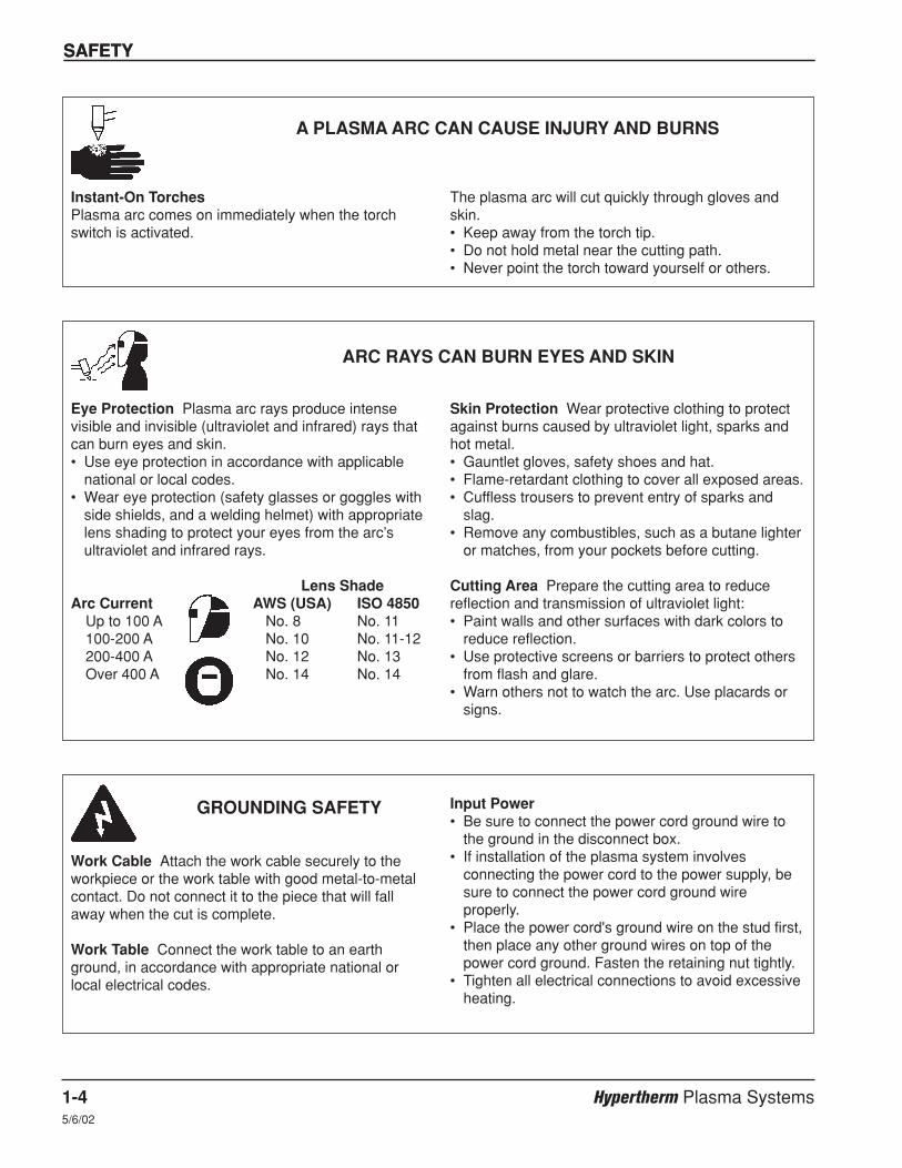
Instant-On TorchesPlasma arc comes on immediately when the torchswitch is activated.
A PLASMA ARC CAN CAUSE INJURY AND BURNS
The plasma arc will cut quickly through gloves andskin.• Keep away from the torch tip.• Do not hold metal near the cutting path.• Never point the torch toward yourself or others.
Eye Protection Plasma arc rays produce intensevisible and invisible (ultraviolet and infrared) rays thatcan burn eyes and skin.• Use eye protection in accordance with applicable
national or local codes.• Wear eye protection (safety glasses or goggles with
side shields, and a welding helmet) with appropriatelens shading to protect your eyes from the arc’sultraviolet and infrared rays.
Lens ShadeArc Current AWS (USA) ISO 4850
Up to 100 A No. 8 No. 11100-200 A No. 10 No. 11-12200-400 A No. 12 No. 13Over 400 A No. 14 No. 14
ARC RAYS CAN BURN EYES AND SKIN
Skin Protection Wear protective clothing to protectagainst burns caused by ultraviolet light, sparks andhot metal.• Gauntlet gloves, safety shoes and hat.• Flame-retardant clothing to cover all exposed areas.• Cuffless trousers to prevent entry of sparks and
slag.• Remove any combustibles, such as a butane lighter
or matches, from your pockets before cutting.
Cutting Area Prepare the cutting area to reducereflection and transmission of ultraviolet light:• Paint walls and other surfaces with dark colors to
reduce reflection. • Use protective screens or barriers to protect others
from flash and glare.• Warn others not to watch the arc. Use placards or
signs.
Work Cable Attach the work cable securely to theworkpiece or the work table with good metal-to-metalcontact. Do not connect it to the piece that will fallaway when the cut is complete.
Work Table Connect the work table to an earthground, in accordance with appropriate national orlocal electrical codes.
GROUNDING SAFETY Input Power• Be sure to connect the power cord ground wire to
the ground in the disconnect box.• If installation of the plasma system involves
connecting the power cord to the power supply, besure to connect the power cord ground wireproperly.
• Place the power cord's ground wire on the stud first,then place any other ground wires on top of thepower cord ground. Fasten the retaining nut tightly.
• Tighten all electrical connections to avoid excessiveheating.
SAFETY
Hypertherm Plasma Systems 1-511-98
SAFETY
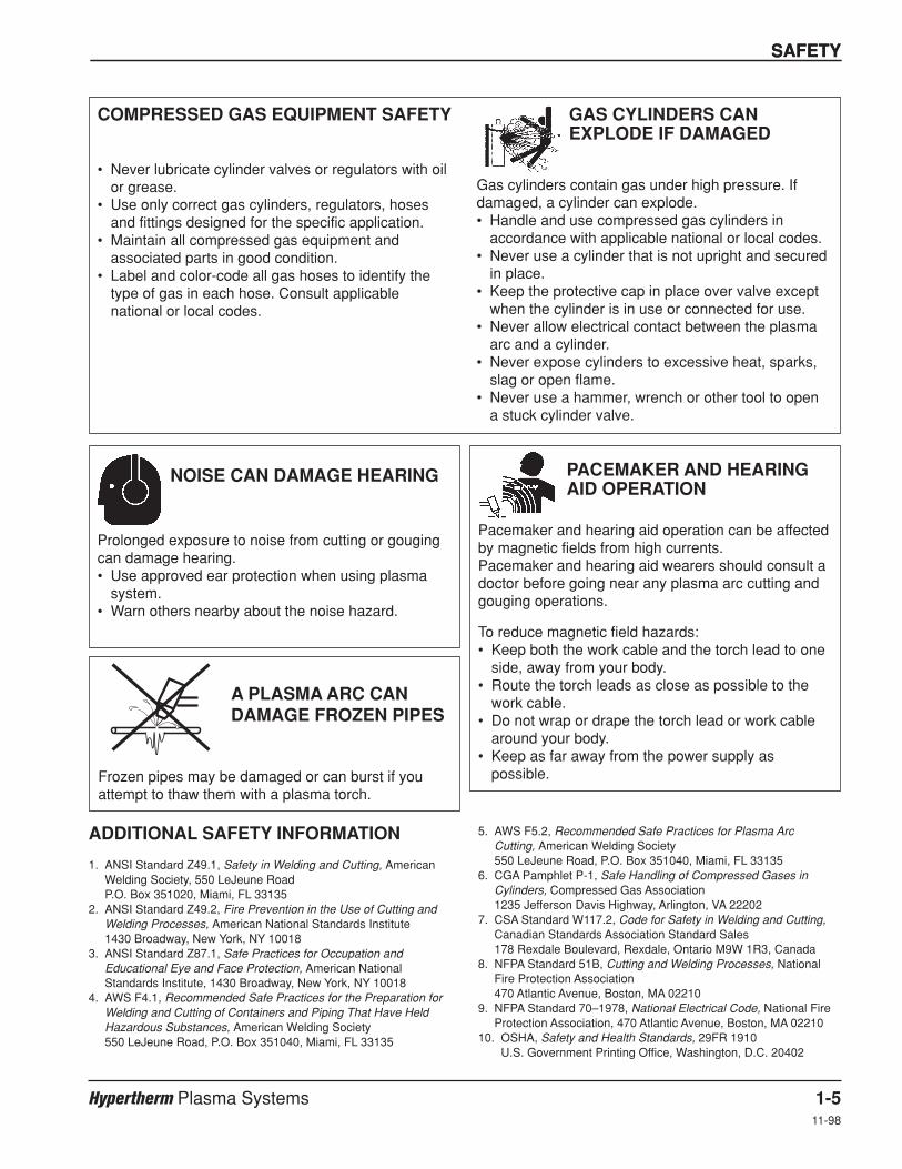
• Never lubricate cylinder valves or regulators with oilor grease.
• Use only correct gas cylinders, regulators, hosesand fittings designed for the specific application.
• Maintain all compressed gas equipment andassociated parts in good condition.
• Label and color-code all gas hoses to identify thetype of gas in each hose. Consult applicablenational or local codes.
GAS CYLINDERS CANEXPLODE IF DAMAGED
COMPRESSED GAS EQUIPMENT SAFETY
Gas cylinders contain gas under high pressure. Ifdamaged, a cylinder can explode.• Handle and use compressed gas cylinders in
accordance with applicable national or local codes.• Never use a cylinder that is not upright and secured
in place.• Keep the protective cap in place over valve except
when the cylinder is in use or connected for use.• Never allow electrical contact between the plasma
arc and a cylinder.• Never expose cylinders to excessive heat, sparks,
slag or open flame.• Never use a hammer, wrench or other tool to open
a stuck cylinder valve.
Prolonged exposure to noise from cutting or gougingcan damage hearing.• Use approved ear protection when using plasma
system.• Warn others nearby about the noise hazard.
NOISE CAN DAMAGE HEARING
Pacemaker and hearing aid operation can be affectedby magnetic fields from high currents.Pacemaker and hearing aid wearers should consult adoctor before going near any plasma arc cutting andgouging operations.
To reduce magnetic field hazards:• Keep both the work cable and the torch lead to one
side, away from your body.• Route the torch leads as close as possible to the
work cable.• Do not wrap or drape the torch lead or work cable
around your body.• Keep as far away from the power supply as
possible.
PACEMAKER AND HEARINGAID OPERATION
ADDITIONAL SAFETY INFORMATION
1. ANSI Standard Z49.1, Safety in Welding and Cutting, AmericanWelding Society, 550 LeJeune RoadP.O. Box 351020, Miami, FL 33135
2. ANSI Standard Z49.2, Fire Prevention in the Use of Cutting andWelding Processes, American National Standards Institute1430 Broadway, New York, NY 10018
3. ANSI Standard Z87.1, Safe Practices for Occupation andEducational Eye and Face Protection, American NationalStandards Institute, 1430 Broadway, New York, NY 10018
4. AWS F4.1, Recommended Safe Practices for the Preparation forWelding and Cutting of Containers and Piping That Have HeldHazardous Substances, American Welding Society550 LeJeune Road, P.O. Box 351040, Miami, FL 33135
5. AWS F5.2, Recommended Safe Practices for Plasma Arc Cutting, American Welding Society550 LeJeune Road, P.O. Box 351040, Miami, FL 33135
6. CGA Pamphlet P-1, Safe Handling of Compressed Gases inCylinders, Compressed Gas Association1235 Jefferson Davis Highway, Arlington, VA 22202
7. CSA Standard W117.2, Code for Safety in Welding and Cutting,Canadian Standards Association Standard Sales178 Rexdale Boulevard, Rexdale, Ontario M9W 1R3, Canada
8. NFPA Standard 51B, Cutting and Welding Processes, NationalFire Protection Association470 Atlantic Avenue, Boston, MA 02210
9. NFPA Standard 70–1978, National Electrical Code, National FireProtection Association, 470 Atlantic Avenue, Boston, MA 02210
10. OSHA, Safety and Health Standards, 29FR 1910U.S. Government Printing Office, Washington, D.C. 20402
A PLASMA ARC CAN DAMAGE FROZEN PIPES
Frozen pipes may be damaged or can burst if youattempt to thaw them with a plasma torch.
SAFETY
1-6 Hypertherm Plasma Systems8-99
SAFETY
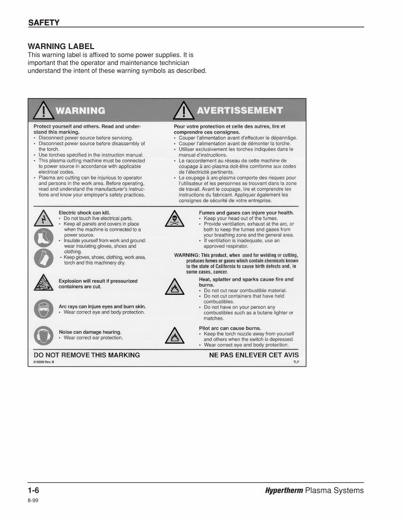
WARNING LABELThis warning label is affixed to some power supplies. It isimportant that the operator and maintenance technicianunderstand the intent of these warning symbols as described.
Hypertherm Systèmes plasma 1a-12/12/01
Section 1a
SÉCURITÉ
Dans cette section :
Identifier les consignes de sécurité.........................................................................................................................1a-2Suivre les instructions de sécurité ..........................................................................................................................1a-2Danger Avertissement Précaution ........................................................................................................................1a-2Le coupage peut provoquer un incendie ou une explosion ....................................................................................1a-2
Prévention des incendies, Prévention des explosions ...................................................................................1a-2Risque d’explosion argon-hydrogène et méthane..........................................................................................1a-2Détonation de l’hydrogène lors du coupage de l’aluminium...........................................................................1a-2
Les chocs électriques peuvent être fatals...............................................................................................................1a-3Prévention des chocs électriques ..................................................................................................................1a-3
Le coupage peut produire des vapeurs toxiques....................................................................................................1a-3L’arc plasma peut provoquer des blessures ou des brûlures .................................................................................1a-4
Torches à allumage instantané ......................................................................................................................1a-4Les rayons de l’arc peuvent brûler les yeux et la peau...........................................................................................1a-4
Protection des yeux, Protection de la peau, Zone de coupage ....................................................................1a-4Mise à la masse et à la terre...................................................................................................................................1a-4
Câble de retour, Table de travail, Alimentation...............................................................................................1a-4Sécurité des bouteilles de gaz comprimé ...............................................................................................................1a-5Les bouteilles de gaz comprimé peuvent exploser en cas de dommages .............................................................1a-5Le bruit peut provoquer des problèmes auditifs......................................................................................................1a-5Pacemakers et prothèses auditives........................................................................................................................1a-5Un arc plasma peut endommager les tuyaux gelés................................................................................................1a-5Étiquette de sécurité ...............................................................................................................................................1a-6
SÉCURITÉ
1a-2 Hypertherm Systèmes plasma2/12/01
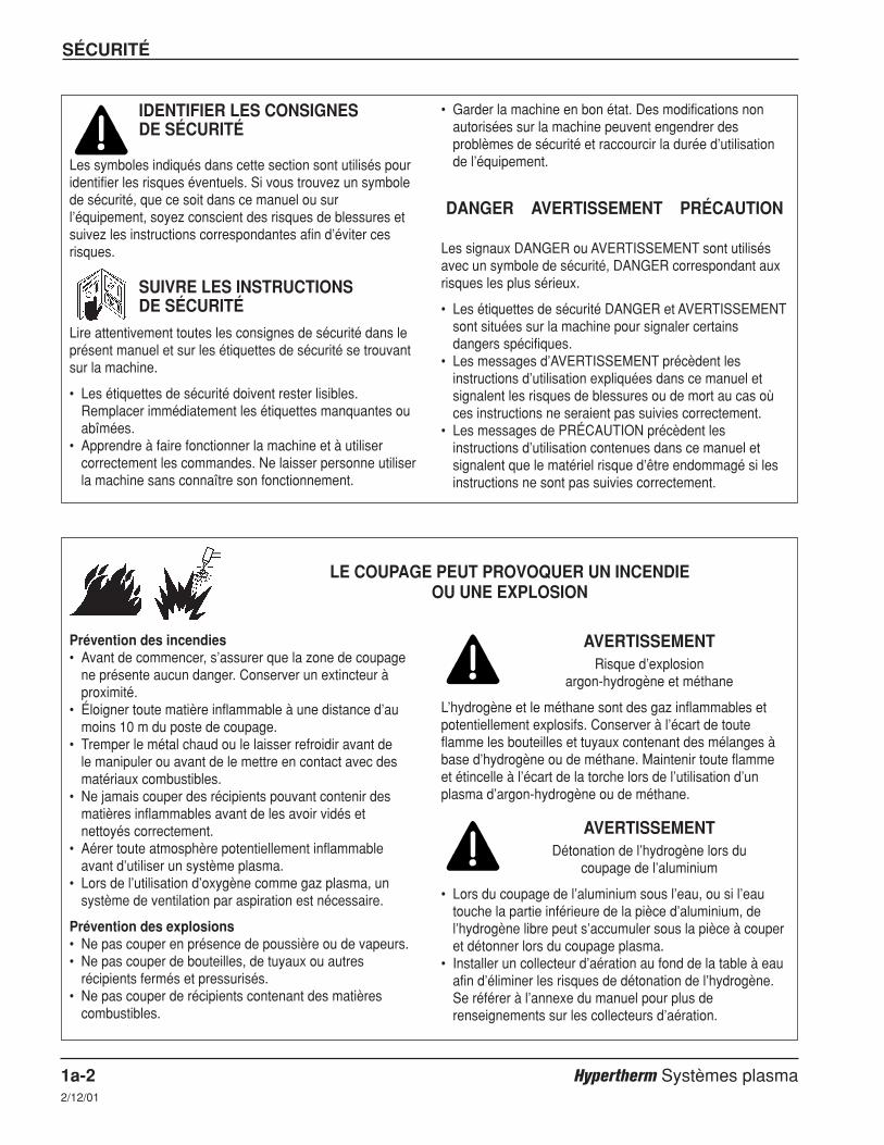
IDENTIFIER LES CONSIGNES DE SÉCURITÉ
Les symboles indiqués dans cette section sont utilisés pouridentifier les risques éventuels. Si vous trouvez un symbolede sécurité, que ce soit dans ce manuel ou surl’équipement, soyez conscient des risques de blessures etsuivez les instructions correspondantes afin d’éviter cesrisques.
SUIVRE LES INSTRUCTIONS DE SÉCURITÉ
Lire attentivement toutes les consignes de sécurité dans leprésent manuel et sur les étiquettes de sécurité se trouvantsur la machine.
• Les étiquettes de sécurité doivent rester lisibles.Remplacer immédiatement les étiquettes manquantes ouabîmées.
• Apprendre à faire fonctionner la machine et à utilisercorrectement les commandes. Ne laisser personne utiliserla machine sans connaître son fonctionnement.
• Garder la machine en bon état. Des modifications nonautorisées sur la machine peuvent engendrer desproblèmes de sécurité et raccourcir la durée d’utilisationde l’équipement.
DANGER AVERTISSEMENT PRÉCAUTION
Les signaux DANGER ou AVERTISSEMENT sont utilisésavec un symbole de sécurité, DANGER correspondant auxrisques les plus sérieux.
• Les étiquettes de sécurité DANGER et AVERTISSEMENTsont situées sur la machine pour signaler certainsdangers spécifiques.
• Les messages d’AVERTISSEMENT précèdent lesinstructions d’utilisation expliquées dans ce manuel etsignalent les risques de blessures ou de mort au cas oùces instructions ne seraient pas suivies correctement.
• Les messages de PRÉCAUTION précèdent lesinstructions d’utilisation contenues dans ce manuel etsignalent que le matériel risque d’être endommagé si lesinstructions ne sont pas suivies correctement.
Prévention des incendies• Avant de commencer, s’assurer que la zone de coupage
ne présente aucun danger. Conserver un extincteur àproximité.
• Éloigner toute matière inflammable à une distance d’aumoins 10 m du poste de coupage.
• Tremper le métal chaud ou le laisser refroidir avant de le manipuler ou avant de le mettre en contact avec desmatériaux combustibles.
• Ne jamais couper des récipients pouvant contenir desmatières inflammables avant de les avoir vidés etnettoyés correctement.
• Aérer toute atmosphère potentiellement inflammableavant d’utiliser un système plasma.
• Lors de l’utilisation d’oxygène comme gaz plasma, unsystème de ventilation par aspiration est nécessaire.
Prévention des explosions• Ne pas couper en présence de poussière ou de vapeurs.• Ne pas couper de bouteilles, de tuyaux ou autres
récipients fermés et pressurisés.• Ne pas couper de récipients contenant des matières
combustibles.
LE COUPAGE PEUT PROVOQUER UN INCENDIEOU UNE EXPLOSION
AVERTISSEMENTRisque d’explosion
argon-hydrogène et méthane
L’hydrogène et le méthane sont des gaz inflammables etpotentiellement explosifs. Conserver à l’écart de touteflamme les bouteilles et tuyaux contenant des mélanges àbase d’hydrogène ou de méthane. Maintenir toute flammeet étincelle à l’écart de la torche lors de l’utilisation d’unplasma d’argon-hydrogène ou de méthane.
AVERTISSEMENTDétonation de l’hydrogène lors du
coupage de l’aluminium
• Lors du coupage de l’aluminium sous l’eau, ou si l’eautouche la partie inférieure de la pièce d’aluminium, del’hydrogène libre peut s’accumuler sous la pièce à couperet détonner lors du coupage plasma.
• Installer un collecteur d’aération au fond de la table à eauafin d’éliminer les risques de détonation de l’hydrogène.Se référer à l’annexe du manuel pour plus derenseignements sur les collecteurs d’aération.
SÉCURITÉ
Hypertherm Systèmes plasma 1a-32/12/01
Toucher une pièce électrique sous tension peut provoquerun choc électrique fatal ou des brûlures graves.
• La mise en fonctionnement du système plasma ferme uncircuit électrique entre la torche et la pièce à couper. Lapièce à couper et tout autre élément en contact avec cettepièce font partie du circuit électrique.
• Ne jamais toucher le corps de la torche, la pièce à couperou l’eau de la table à eau pendant le fonctionnement dusystème plasma.
Prévention des chocs électriques
Tous les systèmes plasma Hypertherm utilisent des hautestensions pour le coupage (souvent de 200 à 400 V). On doit prendre les précautions suivantes quand on utilise lesystème plasma :• Porter des bottes et des gants isolants et garder le corps
et les vêtements au sec.• Ne pas se tenir, s’asseoir ou se coucher sur une surface
mouillée, ni la toucher quand on utilise le système plasma.• S’isoler de la surface de travail et du sol en utilisant des
tapis isolants secs ou des couvertures assez grandespour éviter tout contact physique avec le travail ou le sol.S’il s’avère nécessaire de travailler dans ou près d’unendroit humide, procéder avec une extrême prudence.
• Installer un sectionneur avec fusibles appropriés, àproximité de la source de courant. Ce dispositif permet àl’opérateur d’arrêter rapidement la source de courant encas d’urgence.
• En cas d’utilisation d’une table à eau, s’assurer que cettedernière est correctement mise à la terre.
LES CHOCS ÉLECTRIQUES PEUVENT ÊTRE FATALS
• Installer et mettre à la terre l’équipement selon lesinstructions du présent manuel et conformément auxcodes électriques locaux et nationaux.
• Inspecter fréquemment le cordon d’alimentation primairepour s’assurer qu’il n’est ni endommagé, ni fendu.Remplacer immédiatement un cordon endommagé. Un câble dénudé peut tuer.
• Inspecter et remplacer les câbles de la torche qui sontusés ou endommagés.
• Ne pas saisir la pièce à couper ni les chutes lors ducoupage. Laisser la pièce à couper en place ou sur latable de travail, le câble de retour connecté lors ducoupage.
• Avant de vérifier, de nettoyer ou de remplacer les piècesde la torche, couper l’alimentation ou débrancher la prisede courant.
• Ne jamais contourner ou court-circuiter les verrouillagesde sécurité.
• Avant d’enlever le capot du système ou de la source decourant, couper l’alimentation électrique. Attendre ensuite5 minutes pour que les condensateurs se déchargent.
• Ne jamais faire fonctionner le système plasma sans queles capots de la source de courant ne soient en place.Les raccords exposés de la source de courant sontextrêmement dangereux.
• Lors de l’installation des connexions, attacher tout d’abordla prise de terre appropriée.
• Chaque système plasma Hypertherm est conçu pour êtreutilisé uniquement avec des torches Hyperthermspécifiques. Ne pas utiliser des torches inappropriées quipourraient surchauffer et présenter des risques pour lasécurité.
Le coupage peut produire des vapeurs et des gaz toxiquesqui réduisent le niveau d’oxygène dans l’air et peuventprovoquer des blessures, voire la mort.• Conserver le poste de coupage bien aéré ou utiliser un
masque respiratoire homologué.• Ne pas procéder au coupage près d’endroits où
s’effectuent le dégraissage, le nettoyage ou la vapori-sation. Certains solvants chlorés se décomposent sousl’effet des rayons ultraviolets et forment du phosgène.
• Ne pas couper des métaux peints ou contenant desmatières toxiques comme le zinc (galvanisé), le plomb, lecadmium ou le béryllium, à moins que la zone de travail
LE COUPAGE PEUT PRODUIRE DES VAPEURS TOXIQUES
soit très bien ventilée et que l’opérateur porte un masquerespiratoire. Les revêtements et métaux contenant cesmatières peuvent produire des vapeurs toxiques lors ducoupage.
• Ne jamais couper de récipients pouvant contenir desmatières inflammables avant de les avoir vidés etnettoyés correctement.
• Quand on utilise ce produit pour le soudage ou lecoupage, il dégage des fumées et des gaz quicontiennent des produits chimiques qui, selon l’État deCalifornie, provoquent des anomalies congénitales et,dans certains cas, le cancer.
SÉCURITÉ
1a-4 Hypertherm Systèmes plasma5/6/02
Torches à allumage instantané
L’arc plasma s’allume immédiatement après que la torchesoit mise en marche.
L’ARC PLASMA PEUT PROVOQUER DES BLESSURES OU DES BRÛLURES
L’arc plasma coupe facilement les gants et la peau.• Rester éloigné de l’extrémité de la torche.• Ne pas tenir de métal près de la trajectoire de coupe.• Ne jamais pointer la torche vers soi ou d’autres
personnes.
Protection des yeux Les rayons de l’arc plasmaproduisent de puissants rayons visibles ou invisibles(ultraviolets et infrarouges) qui peuvent brûler les yeux et lapeau.• Utiliser des lunettes de sécurité conformément aux codes
locaux ou nationaux en vigueur.• Porter des lunettes de protection (lunettes ou masque
muni d’écrans latéraux et encore masque de soudure)avec des verres teintés appropriés pour protéger les yeuxdes rayons ultraviolets et infrarouges de l’arc.
Puissance des verres teintésCourant de l’arc AWS (É.-U.) ISO 4850Jusqu’à 100 A No 8 No 11100-200 A No 10 No 11-12200-400 A No 12 No 13Plus de 400 A No 14 No 14
Protection de la peau Porter des vêtements de sécuritépour se protéger contre les brûlures que peuvent causer lesrayons ultraviolets, les étincelles et le métal brûlant :
LES RAYONS DE L’ARC PEUVENT BRÛLER LES YEUX ET LA PEAU
• Gants à crispin, chaussures et casque de sécurité.• Vêtements ignifuges couvrant toutes les parties exposées
du corps.• Pantalon sans revers pour éviter que des étincelles ou
des scories puissent s’y loger.• Avant le coupage, retirer de ses poches tout objet
combustible comme les briquets au butane ou lesallumettes.
Zone de coupage Préparer la zone de coupage afin deréduire la réverbération et la transmission de la lumièreultraviolette :• Peindre les murs et autres surfaces de couleur sombre
pour réduire la réflexion de la lumière.• Utiliser des écrans et autres dispositifs de protection afin
de protéger les autres personnes de la lumière et de laréverbération.
• Prévenir les autres personnes de ne pas regarder l’arc.Utiliser des affiches ou des panneaux.
Câble de retour Bien fixer le câble de retour (ou demasse) à la pièce à couper ou à la table de travail de façonà assurer un bon contact métal-métal. Ne pas fixer le câblede retour à la partie de la pièce qui doit se détacher.
Table de travail Raccorder la table de travail à la terre,conformément aux codes de sécurité locaux ou nationauxappropriés.
MISE À LA MASSE ET À LA TERRE Alimentation• S’assurer que le fil de terre du cordon d’alimentation est
connecté à la terre dans le coffret du sectionneur.• S’il est nécessaire de brancher le cordon d’alimentation à
la source de courant lors de l’installation du système,s’assurer que le fil de terre est correctement branché.
• Placer tout d’abord le fil de terre du cordon d’alimentationsur le plot de mise à la terre puis placer les autres fils deterre par-dessus. Bien serrer l’écrou de retenue.
• S’assurer que toutes les connexions sont bien serréespour éviter la surchauffe.
SÉCURITÉ
Hypertherm Systèmes plasma 1a-52/12/01
• Ne jamais lubrifier les robinets des bouteilles ou lesrégulateurs avec de l’huile ou de la graisse.
• Utiliser uniquement les bouteilles, régulateurs, tuyaux etaccessoires appropriés et conçus pour chaque applicationspécifique.
• Entretenir l’équipement et les pièces d’équipement à gazcomprimé afin de les garder en bon état.
• Étiqueter et coder avec des couleurs tous les tuyaux degaz afin d’identifier le type de gaz contenu dans chaquetuyau. Se référer aux codes locaux ou nationaux envigueur.
LES BOUTEILLES DE GAZCOMPRIMÉ PEUVENT EXPLOSEREN CAS DE DOMMAGES
SÉCURITÉ DES BOUTEILLES DE GAZ COMPRIMÉ
Les bouteilles de gaz contiennent du gaz à haute pression.Si une bouteille est endommagée, elle peut exploser.• Manipuler et utiliser les bouteilles de gaz comprimé
conformément aux codes locaux ou nationaux.• Ne jamais utiliser une bouteille qui n’est pas placée à la
verticale et bien assujettie.• Le capuchon de protection doit être placé sur le robinet
sauf si la bouteille est en cours d’utilisation ou connectéepour utilisation.
• Éviter à tout prix le contact électrique entre l’arc plasma etune bouteille.
• Ne jamais exposer des bouteilles à une chaleurexcessive, aux étincelles, aux scories ou aux flammesnues.
• Ne jamais utiliser des marteaux, des clés ou d’autresoutils pour débloquer le robinet des bouteilles.
Une exposition prolongée au bruit du coupage ou dugougeage peut provoquer des problèmes auditifs.• Utiliser un casque de protection homologué lors de
l’utilisation du système plasma.• Prévenir les personnes aux alentours des risques
encourus en cas d’exposition au bruit.
LE BRUIT PEUT PROVOQUER DESPROBLÈMES AUDITIFS
Les champs magnétiques produits par les courants à hautetension peuvent affecter le fonctionnement des prothèsesauditives et des pacemakers. Les personnes portant cetype d’appareil doivent consulter un médecin avant des’approcher d’un lieu où s’effectue le coupage ou legougeage plasma.
Pour réduire les risques associés aux champs magnétiques :• Garder loin de soi et du même côté du corps le câble de
retour et le faisceau de la torche.• Faire passer le faisceau de la torche le plus près possible
du câble de retour.• Ne pas s’enrouler le faisceau de la torche ou le câble de
retour autour du corps.• Se tenir le plus loin possible de la source de courant.
PACEMAKERS ET PROTHÈSES AUDITIVES
Les tuyaux gelés peuvent être endommagés ou éclatersi l'on essaie de les dégeler avec une torche plasma.
UN ARC PLASMAPEUT ENDOMMAGERLES TUYAUX GELÉS

SÉCURITÉ
1a-6 Hypertherm Systèmes plasma2/12/01
Étiquette de sécuritéCette étiquette est affichée sur la source de courant. Il est importantque l’utilisateur et le technicien de maintenance comprennent lasignification des symboles de sécurité.

HySpeed HT2000LHF Instruction Manual 2-17
HySpeed HT2000LHF System Components
See Figure 3-2 in Section 3 for details of the system interconnections.
Power Supply
The LHF power supply houses two 100-amp, 15 kHz choppers, the torch's high-frequency starting circuit and anoptional internal Torch Height Control (THC).
HySpeed LHF Machine Torch
The LHF machine torch is liquid-cooled and capable of cutting most metals from gauge to 2-inch (50 mm) thicknessand from gauge to 1-inch (25 mm) thickness for production cutting. To achieve consumable long life, all cutsmust begin and end on the plate surface.
Gas Console
This unit houses metering and solenoid valves for shield and plasma gases, flow meters, pressure gauges forplasma gases, and a pressure gauge for the shield gas supply.
Argon-Hydrogen Manifold – Optional
This unit houses a flowmeter for argon-hydrogen, a metering valve, a plasma gas outlet switch and a plasma-offvalve.
Digital Remote Voltage & Current Control Console
This unit includes LED displays that indicate the setpoints for volts and amperes prior to starting the arc. Thedisplays then automatically display the actual values of the voltage and current while cutting. The digital remote haspotentiometers to set and adjust the voltage and current.
Programmable Remote Voltage & Current Control Console
This unit includes LED displays that indicate the setpoints for volts and amperes prior to starting the arc. Thedisplays then automatically display the actual values of the voltage and current while cutting. The programmableremote functions are controlled by the CNC.
Section 2
SPECIFICATIONS

SPECIFICATIONS
2-2 HySpeed HT2000LHF Instruction Manual7
Remote Current Control Console
This unit contains a manually adjustable thumbwheel to set arc current only.
Initial Height Sensing - Optional
This unit, used with 2 inductive probes, is designed to automatically detect the workpiece surface and move thetorch to the pierce position. This system can be used for underwater cutting, cutting at the water line, or cuttingabove water.
Timer/Counter – Optional
The timer/counter allows the operator to monitor the number of arc starts and the cumulative time that the arc is onin hours. The arc starts can be reset.
Water Muffler – Optional
The water muffler for the LHF system is an option which greatly improves cutting safety and pollution controlcapabilities. The water muffler can be used to cut above, below and at the water line. Refer to the Water Mufflerinstruction manual 802050 for more detailed information. The water muffler cannot be used with the stainless steeltorch.
CommandTHC – Optional
The CommandTHC is an external torch height control and initial height sensing system designed for plasma cuttingapplications on an x-y cutting table. Refer to the CommandTHC instruction manual 802780 for more detailedinformation.
SpecificationsSystem Requirements
Power Requirements:Refer to LHF power supply specifications below:
Gas Requirements:Plasma Gas Types........................................................Oxygen, Nitrogen, Air,
Argon-Hydrogen (H35 = 35% Hydrogen/ 65% Argon)Shield Gas Types..........................................................Air, Nitrogen, Carbon Dioxide
Gas Quality:Oxygen .........................................................................99.5% pure (liquid gas recommended)Nitrogen ........................................................................99.995% pure (liquid gas recommended)Air .................................................................................Clean, dry, oil-free (compressed or liquid gas recommended)Carbon Dioxide .............................................................99.5% pure (compressed or liquid gas recommended)
Plasma Gas Inlet Pressures and Flow Rates:Air .................................................................................90 psi +/- 10 psi (6.2 bar +/- 0.7 bar) at 82 scfh (2322 l/h)Oxygen .........................................................................120 psi +/- 10 psi (8.3 bar +/- 0.7 bar) at 90 scfh (2549 l/h)Nitrogen ........................................................................120 psi +/- 10 psi (8.3 bar +/- 0.7 bar) at 80 scfh (2265 l/h)Argon-Hydrogen ...........................................................120 psi +/- 10 psi (8.3 bar +/- 0.7 bar) at 105 scfh (2973 l/h)
Shield Gas Inlet Pressures and Flow Rates:Air .................................................................................90 psi +/- 10 psi (6.2 bar +/- 0.7 bar) at 280 scfh (7929 l/h)Carbon Dioxide .............................................................90 psi +/- 10 psi (6.2 bar +/- 0.7 bar) at 220 scfh (6230 l/h)Nitrogen ........................................................................90 psi +/- 10 psi (6.2 bar +/- 0.7 bar) at 275 scfh (7787 l/h)Oxygen .........................................................................120 psi +/- 10 psi (8.3 bar +/- 0.7 bar) at 35 scfh (991 l/h)

SPECIFICATIONS
HySpeed HT2000LHF Instruction Manual 2-36
Power Supply
Maximum OCV (U0) ......................................................280 VDCOutput Current (I2) ........................................................40 – 200 ampsOutput Voltage (U2) ......................................................150 VDCDuty Cycle Rating (X) ..................................................100% up to 30 kW. Beyond 30 kW, Duty Cycle (X) =
(30 kW/Actual Power)2 Eg: If Actual Power = 32 kW, then DutyCycle (X) = (30 kW/32 kW)2 = 88%
Ambient Temperatures/Duty Cycle ...............................Power supplies will operate between +14° and 104° F (-10° and+40° C). Power supplies operated in an ambient temperatureabove 86° F (30° C) may show some decrease in duty cycle.
Power Factor (cosϕ) .....................................................0.86
Input Power (Input Voltage (U1) x Input Current ( I1)):
073227 with THC; 073228 without THC .......................200 VAC, 3PH, 50 Hz, 108 amps073229 with THC; 073230 without THC .......................208 VAC, 3PH, 60 Hz, 104 amps073231 with THC; 073232 without THC .......................240 VAC, 3PH, 60 Hz, 90 amps 073235 with THC; 073236 without THC .......................400 VAC, CE, 3PH, 50 Hz, 56 amps073262 with THC; 073263 without THC .......................440 VAC, 3PH, 50-60 Hz, 49 amps073233 with THC; 073234 without THC .......................480 VAC, 3PH, 60 Hz, 45 amps073237 with THC; 073238 without THC .......................600 VAC, 3PH, 60 Hz, 36 amps
Dimensions and Weight:Width.............................................................................28-1/4" (710 mm)Height ...........................................................................35-1/2" (900 mm); 40-3/4" (1035 mm) on CE unitsDepth ............................................................................41-1/4" (1045 mm)Weight...........................................................................780 lbs (351 kg); 800 lbs (363 kg) on CE unitsCooling..........................................................................Forced Air (Class F)Coolant Tank Capacity ..................................................2.9 gallons (11 liters)
Maximum cutting thickness...........................................2" (50 mm)Maximum current at 100% duty cycle...........................200 amps
Plasma and Shield Gas Flow........................................Refer to the Cut Charts in the Operation section for specific gasrequirements.
Water coolant flow rate .................................................0.8 gpm (3.0 l/min)Weight...........................................................................3 lbs (1.36 kg)
Figure 2-1 LHF Machine Torch (standard torch shown. See Section 6 for figure of stainless steel torch)
6" (152 mm)
15.4" (391 mm)
23.25" (590 mm)
2" (51 mm)
4.3" (109 mm)
2" (50 mm) or1.75" (44 mm)
See Sect. 6
HySpeed LHF Machine Torch
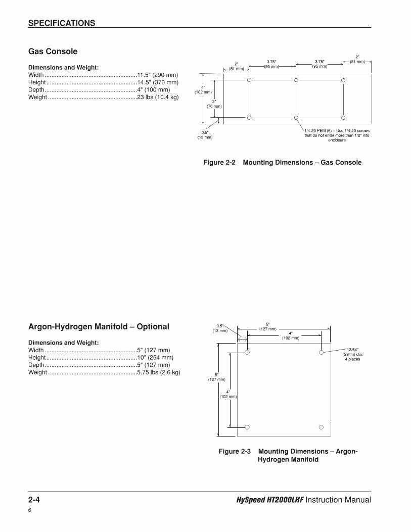
4"
4"
5"
5"
SPECIFICATIONS
2-4 HySpeed HT2000LHF Instruction Manual6
Gas Console
Dimensions and Weight:Width .......................................................11.5" (290 mm)Height ......................................................14.5" (370 mm)Depth.......................................................4" (100 mm)Weight .....................................................23 lbs (10.4 kg)
Argon-Hydrogen Manifold – Optional
Dimensions and Weight:Width .......................................................5" (127 mm)Height ......................................................10" (254 mm)Depth.......................................................5" (127 mm)Weight .....................................................5.75 lbs (2.6 kg)
4"(102 mm)
3"(76 mm)
5"(127 mm)
5"(127 mm)
4"(102 mm)
4"(102 mm)
2"(51 mm)
2"(51 mm)
0.5"(13 mm)
3.75"(95 mm)
3.75"(95 mm)
1/4-20 PEM (6) – Use 1/4-20 screwsthat do not enter more than 1/2" into
enclosure
Figure 2-2 Mounting Dimensions – Gas Console
13/64"(5 mm) dia.
4 places
Figure 2-3 Mounting Dimensions – Argon-Hydrogen Manifold
0.5"(13 mm)
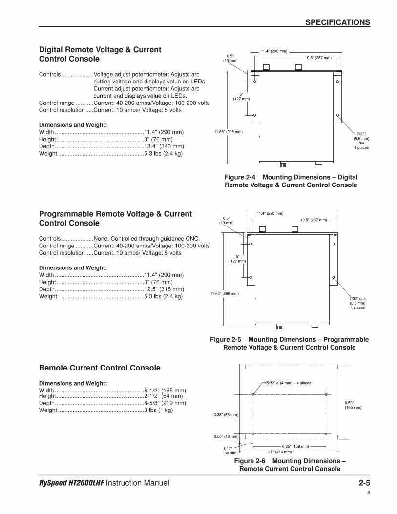
SPECIFICATIONS
HySpeed HT2000LHF Instruction Manual 2-56
Digital Remote Voltage & Current Control Console
Controls....................Voltage adjust potentiometer: Adjusts arccutting voltage and displays value on LEDs.Current adjust potentiometer: Adjusts arccurrent and displays value on LEDs.
Control range ...........Current: 40-200 amps/Voltage: 100-200 voltsControl resolution.....Current: 10 amps/ Voltage: 5 volts
Dimensions and Weight:Width .......................................................11.4" (290 mm)Height ......................................................3" (76 mm)Depth.......................................................13.4" (340 mm)Weight .....................................................5.3 lbs (2.4 kg)
Programmable Remote Voltage & Current Control Console
Controls....................None. Controlled through guidance CNC.Control range ...........Current: 40-200 amps/Voltage: 100-200 voltsControl resolution.....Current: 10 amps/ Voltage: 5 volts
Dimensions and Weight:Width .......................................................11.4" (290 mm)Height ......................................................3" (76 mm)Depth.......................................................12.5" (318 mm)Weight .....................................................5.3 lbs (2.4 kg)
Remote Current Control Console
Dimensions and Weight:Width .......................................................6-1/2" (165 mm)Height ......................................................2-1/2" (64 mm)Depth.......................................................8-5/8" (219 mm)Weight .....................................................3 lbs (1 kg)
10.5" (267 mm)
11.4" (290 mm)
7/32"(5.5 mm)
dia. 4 places
11.65" (296 mm)
5" (127 mm)
0.5" (13 mm)
Figure 2-4 Mounting Dimensions – DigitalRemote Voltage & Current Control Console
10.5" (267 mm)
11.4" (290 mm)
7/32" dia. (5.5 mm)4 places
11.65" (296 mm)
5" (127 mm)
0.5" (13 mm)
Figure 2-5 Mounting Dimensions – ProgrammableRemote Voltage & Current Control Console
Figure 2-6 Mounting Dimensions – Remote Current Control Console
5/32" ø (4 mm) – 4 places
3.38" (86 mm)
6.25" (159 mm)8.5" (216 mm)
0.50" (13 mm)
1.17" (30 mm)
6.50" (165 mm)
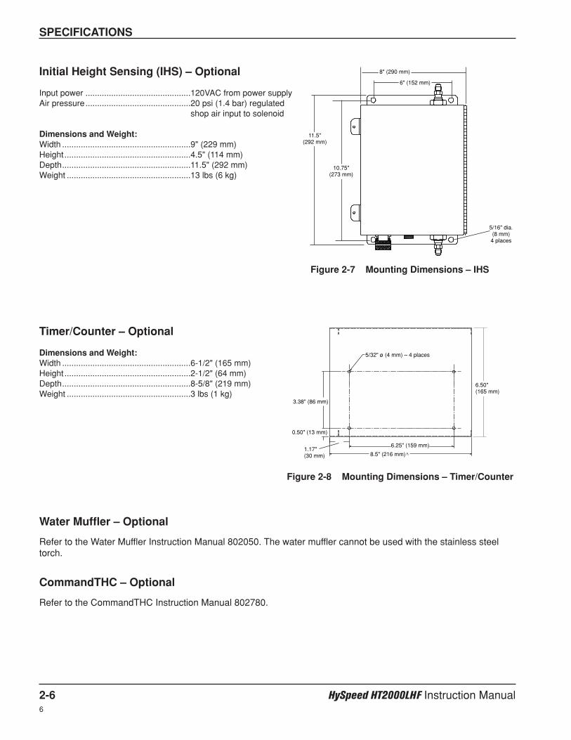
SPECIFICATIONS
2-6 HySpeed HT2000LHF Instruction Manual6
Initial Height Sensing (IHS) – Optional
Input power .............................................120VAC from power supplyAir pressure.............................................20 psi (1.4 bar) regulated
shop air input to solenoid
Dimensions and Weight:Width .......................................................9" (229 mm)Height ......................................................4.5" (114 mm)Depth.......................................................11.5" (292 mm)Weight .....................................................13 lbs (6 kg)
Timer/Counter – Optional
Dimensions and Weight:Width .......................................................6-1/2" (165 mm)Height ......................................................2-1/2" (64 mm)Depth.......................................................8-5/8" (219 mm)Weight .....................................................3 lbs (1 kg)
Water Muffler – Optional
Refer to the Water Muffler Instruction Manual 802050. The water muffler cannot be used with the stainless steeltorch.
CommandTHC – Optional
Refer to the CommandTHC Instruction Manual 802780.
6" (152 mm)
8" (290 mm)
5/16" dia. (8 mm)
4 places
11.5" (292 mm)
10.75" (273 mm)
Figure 2-7 Mounting Dimensions – IHS
Figure 2-8 Mounting Dimensions – Timer/Counter
5/32" ø (4 mm) – 4 places
3.38" (86 mm)
6.25" (159 mm)
8.5" (216 mm)
0.50" (13 mm)
1.17"(30 mm)
6.50"(165 mm)
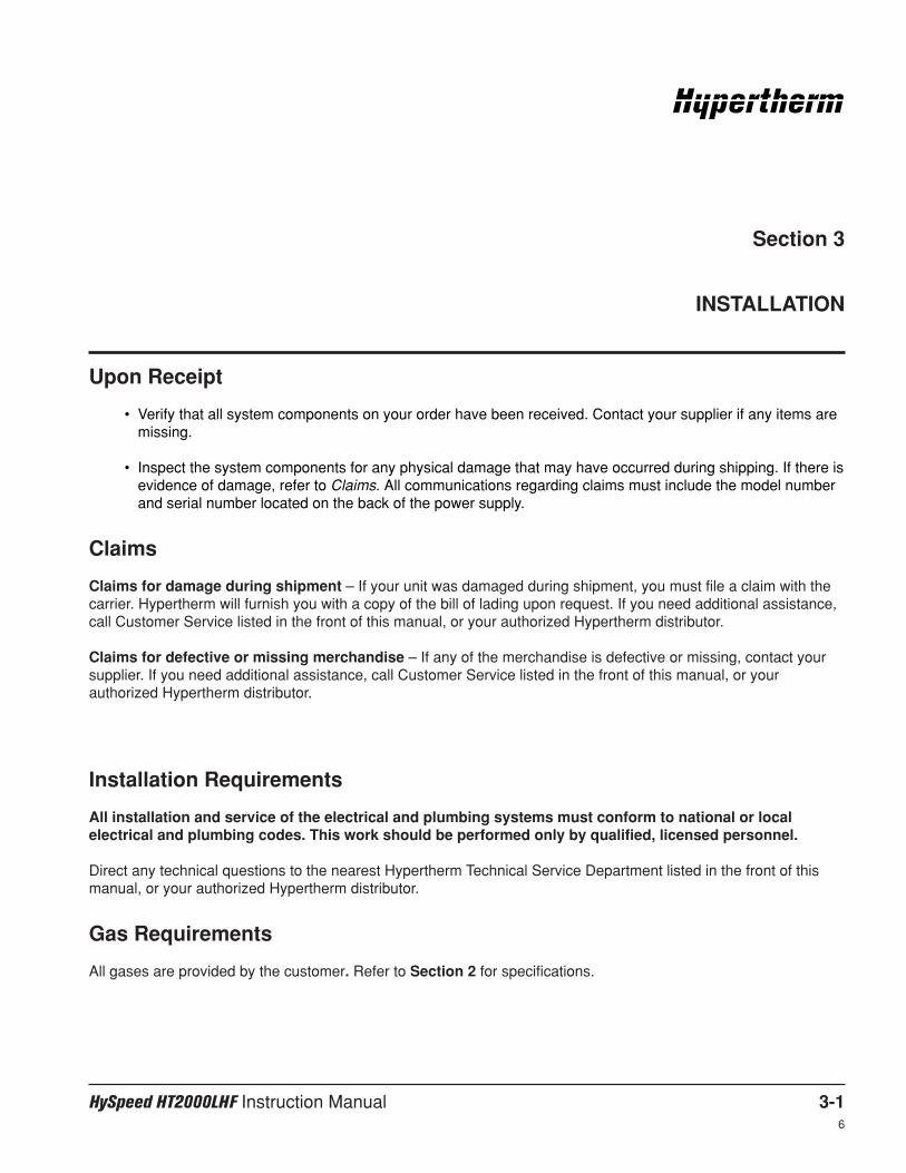
HySpeed HT2000LHF Instruction Manual 3-16
Section 3
INSTALLATION
Installation Requirements
All installation and service of the electrical and plumbing systems must conform to national or localelectrical and plumbing codes. This work should be performed only by qualified, licensed personnel.
Direct any technical questions to the nearest Hypertherm Technical Service Department listed in the front of thismanual, or your authorized Hypertherm distributor.
Gas Requirements
All gases are provided by the customer. Refer to Section 2 for specifications.
Upon Receipt
• Verify that all system components on your order have been received. Contact your supplier if any items aremissing.
• Inspect the system components for any physical damage that may have occurred during shipping. If there isevidence of damage, refer to Claims. All communications regarding claims must include the model numberand serial number located on the back of the power supply.
Claims
Claims for damage during shipment – If your unit was damaged during shipment, you must file a claim with thecarrier. Hypertherm will furnish you with a copy of the bill of lading upon request. If you need additional assistance,call Customer Service listed in the front of this manual, or your authorized Hypertherm distributor.
Claims for defective or missing merchandise – If any of the merchandise is defective or missing, contact yoursupplier. If you need additional assistance, call Customer Service listed in the front of this manual, or yourauthorized Hypertherm distributor.
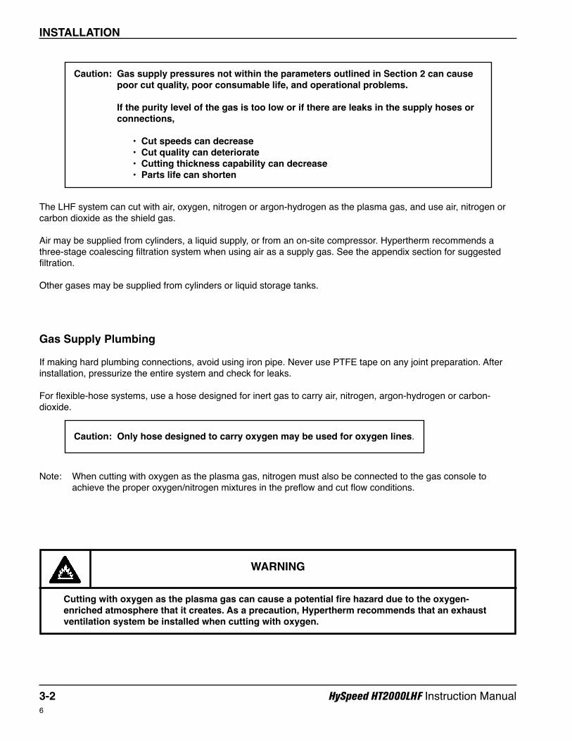
INSTALLATION
3-2 HySpeed HT2000LHF Instruction Manual6
Caution: Gas supply pressures not within the parameters outlined in Section 2 can causepoor cut quality, poor consumable life, and operational problems.
If the purity level of the gas is too low or if there are leaks in the supply hoses orconnections,
• Cut speeds can decrease• Cut quality can deteriorate• Cutting thickness capability can decrease• Parts life can shorten
Caution: Only hose designed to carry oxygen may be used for oxygen lines.
The LHF system can cut with air, oxygen, nitrogen or argon-hydrogen as the plasma gas, and use air, nitrogen orcarbon dioxide as the shield gas.
Air may be supplied from cylinders, a liquid supply, or from an on-site compressor. Hypertherm recommends athree-stage coalescing filtration system when using air as a supply gas. See the appendix section for suggestedfiltration.
Other gases may be supplied from cylinders or liquid storage tanks.
Gas Supply Plumbing
If making hard plumbing connections, avoid using iron pipe. Never use PTFE tape on any joint preparation. Afterinstallation, pressurize the entire system and check for leaks.
For flexible-hose systems, use a hose designed for inert gas to carry air, nitrogen, argon-hydrogen or carbon-dioxide.
WARNING
Cutting with oxygen as the plasma gas can cause a potential fire hazard due to the oxygen-enriched atmosphere that it creates. As a precaution, Hypertherm recommends that an exhaustventilation system be installed when cutting with oxygen.
Note: When cutting with oxygen as the plasma gas, nitrogen must also be connected to the gas console toachieve the proper oxygen/nitrogen mixtures in the preflow and cut flow conditions.
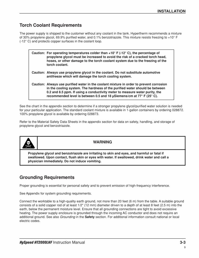
INSTALLATION
HySpeed HT2000LHF Instruction Manual 3-39
Torch Coolant Requirements
The power supply is shipped to the customer without any coolant in the tank. Hypertherm recommends a mixture of 30% propylene glycol, 69.9% purified water, and 0.1% benzotriazole. This mixture resists freezing to +10° F (-12° C) and protects copper surfaces in the coolant loop.
See the chart in the appendix section to determine if a stronger propylene glycol/purified water solution is neededfor your particular application. The standard coolant mixture is available in 1-gallon containers by ordering 028872.100% propylene glycol is available by ordering 028873.
Refer to the Material Safety Data Sheets in the appendix section for data on safety, handling, and storage ofpropylene glycol and benzotriazole.
Grounding Requirements
Proper grounding is essential for personal safety and to prevent emission of high-frequency interference.
See Appendix for system grounding requirements.
Connect the worktable to a high-quality earth ground, not more than 20 feet (6 m) from the table. A suitable groundconsists of a solid copper rod of at least 1/2" (12 mm) diameter driven to a depth of at least 8 feet (2.5 m) into theearth, below the permanent moisture level. Ensure that all grounding connections are tight to avoid excessiveheating. The power supply enclosure is grounded through the incoming AC conductor and does not require anadditional ground. See also Grounding in the Safety section. For additional information consult national or localelectric codes.
Caution: For operating temperatures colder than +10° F (-12° C), the percentage ofpropylene glycol must be increased to avoid the risk of a cracked torch head,hoses, or other damage to the torch coolant system due to the freezing of thetorch coolant.
Caution: Always use propylene glycol in the coolant. Do not substitute automotiveantifreeze which will damage the torch cooling system.
Caution: Always use purified water in the coolant mixture in order to prevent corrosionin the cooling system. The hardness of the purified water should be between 0.2 and 8.5 ppm. If using a conductivity meter to measure water purity, therecommended level is between 0.5 and 18 µSiemens/cm at 77° F (25° C).
WARNING
Propylene glycol and benzotriazole are irritating to skin and eyes, and harmful or fatal ifswallowed. Upon contact, flush skin or eyes with water. If swallowed, drink water and call aphysician immediately. Do not induce vomiting.
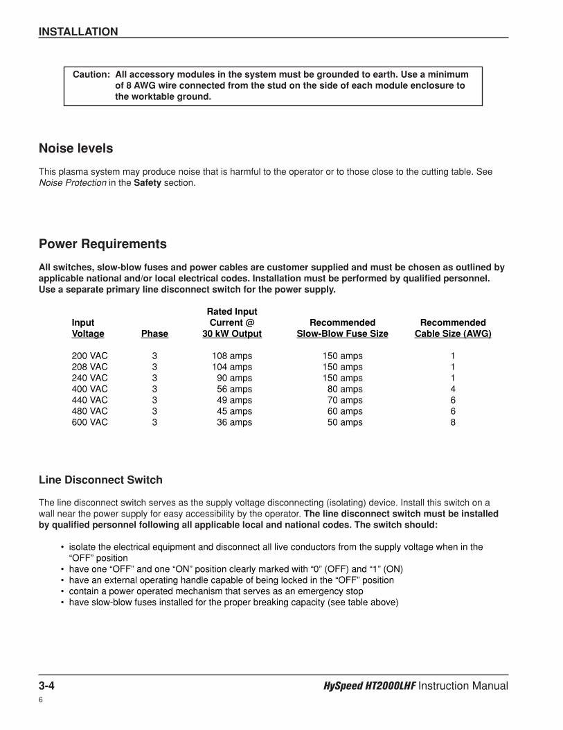
INSTALLATION
3-4 HySpeed HT2000LHF Instruction Manual6
Noise levels
This plasma system may produce noise that is harmful to the operator or to those close to the cutting table. SeeNoise Protection in the Safety section.
Power Requirements
All switches, slow-blow fuses and power cables are customer supplied and must be chosen as outlined byapplicable national and/or local electrical codes. Installation must be performed by qualified personnel.Use a separate primary line disconnect switch for the power supply.
Rated InputInput Current @ Recommended RecommendedVoltage Phase 30 kW Output Slow-Blow Fuse Size Cable Size (AWG)
200 VAC 3 108 amps 150 amps 1208 VAC 3 104 amps 150 amps 1240 VAC 3 90 amps 150 amps 1400 VAC 3 56 amps 80 amps 4440 VAC 3 49 amps 70 amps 6480 VAC 3 45 amps 60 amps 6600 VAC 3 36 amps 50 amps 8
Line Disconnect Switch
The line disconnect switch serves as the supply voltage disconnecting (isolating) device. Install this switch on awall near the power supply for easy accessibility by the operator. The line disconnect switch must be installedby qualified personnel following all applicable local and national codes. The switch should:
• isolate the electrical equipment and disconnect all live conductors from the supply voltage when in the“OFF” position
• have one “OFF” and one “ON” position clearly marked with “0” (OFF) and “1” (ON)• have an external operating handle capable of being locked in the “OFF” position• contain a power operated mechanism that serves as an emergency stop• have slow-blow fuses installed for the proper breaking capacity (see table above)
Caution: All accessory modules in the system must be grounded to earth. Use a minimumof 8 AWG wire connected from the stud on the side of each module enclosure tothe worktable ground.
INSTALLATION
HySpeed HT2000LHF Instruction Manual 3-56
Power Cable
Wire sizes vary based on the distance of the receptacle from the main box. The wire sizes listed in the table abovewere taken from the National Electric Code 1990 handbook, table 310.16. Use a 4-conductor Type SO input powercable with a conductor temperature rating of 140°F (60°C). The cable should be installed only by a licensedelectrician.
Note: A lifting eye is provided for moving the power supply into place with a crane or hoist. It may also be movedby forklift if the forks are long enough to extend the entire length of the base. Take care when lifting with theforks so that the underside of the power supply is not damaged.
• Place the power supply in an area that is free of excessive moisture, has proper ventilation, and is relativelyclean. Allow room for accessing the sides of the power supply for servicing.
• Cooling air is drawn in through the front panel grating, and is exhausted through the rear of the unit by acooling fan. Do not place any filter device over the air intake locations. This reduces cooling efficiency andVOIDS THE WARRANTY.
Positioning the Power Supply
WARNING
Remove all electrical connections to power supply before moving or positioning. Transportingunit can cause personal injury and equipment damage.
WARNING
The line disconnect switch must be in the OFF position before making the power cableconnections! In the U.S., use a "lock-out/tag-out" procedure until installation is complete. Inother countries, follow appropriate local or national safety procedures.
Connecting the Power

INSTALLATION
3-6 HySpeed HT2000LHF Instruction Manual10
1. Insert the power cable through the strain relief at the lower left rear of the power supply. Connect the powercable leads to TB1 located at the center wall, right side.
2. Connect the power leads to the L1, L2, and L3 terminals of TB1. See Fig. 3-1.
3. Connect the ground lead as shown.
Figure 3-1 Power Cable Connections
Ground leadTo connect the powercable to the 400V CEpower supplies refer tothe appendix section.
WARNING
There is line voltage at the contactor if the line disconnect switch is in the ON position, even if theON (l) pushbutton on the power supply has not been pressed. As a common safety practice, ALWAYSverify that the line disconnect switch is in the OFF position before installing, disconnecting orservicing in this area.
Connecting the Power (continued)

INSTALLATION
HySpeed HT2000LHF Instruction Manual 3-76
Power Cable from LHF Power Supply to Power Source.
1. Be certain that the line disconnect switch is in the OFF position and remains in the OFF position for theremainder of the installation of the LHF system.
2. Connect the power cord leads to the line disconnect switch following local and applicable electrical codes.
Torch Lifter Requirements
The LHF system requires a high-quality, motorized torch lifter with sufficient travel to cover all cutting thicknessrequirements. The lifter must provide 10 inches (254 mm) of vertical travel. The unit should have a constantspeed of at least 20 ipm (508 mm/min) with positive braking. A unit which drifts through the stop point is notacceptable.
Optional Equipment
Water Muffler
Refer to Water Muffler instruction manual 802050. A power cable for the Water Muffler pump must be provided bythe customer. The pumps provided by Hypertherm take a three-phase input. Part numbers and correspondingvoltages are listed in the Water Muffler manual. Input current information is provided on the motor data plate.Present pump systems all draw less than 20 amps and cable sizes should be selected accordingly.
The water muffler cannot be used with the stainless steel torch.
System Units Placement
• Position all required units prior to making electrical, gas and interface connections.
• Ground all external modules in the LHF system to earth.
• To prevent leaks in the system, tighten all gas and water connections to the following specifications:
Use 2 wrenches when tightening to prevent damage to the mating component.
Use the diagram on the following 2 pages to make system interconnections. Follow the number guide on thediagram to find out specific information on each cable, hose or connection. The numbered items are detailed on thepages following the interconnection diagram.
Gas or water Torque Specification
hose size lbf-in lbf-ft kgf-cm
up to 3/8" 75-85 6.25-7 86-981/2" 360-480 30-40 415-550
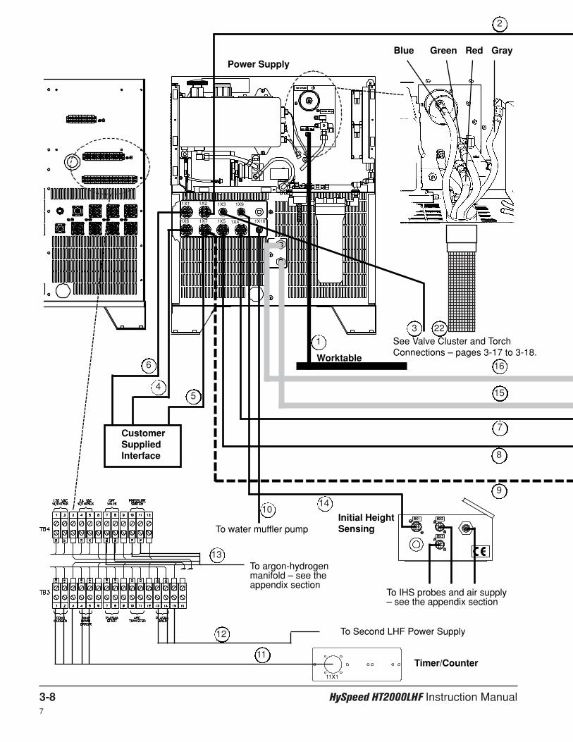
3-8 HySpeed HT2000LHF Instruction Manual7
See Valve Cluster and TorchConnections – pages 3-17 to 3-18.
To Second LHF Power Supply
11X1
Timer/Counter11
12
Blue Green Red Gray
1
2
3
45
CustomerSuppliedInterface
6
Initial HeightSensing
To IHS probes and air supply– see the appendix section
To water muffler pump
To argon-hydrogenmanifold – see theappendix section
Worktable
Power Supply
7
8
9
10
13
14
16
15
22
1X3 1X91X1 1X2
1X6 1X7 1X5 1X4 1X10

HySpeed HT2000LHF Instruction Manual 3-96
Digital Remote
Programmable Remote
Remote Current
To shield gas supply
To oxygen gas supply
To nitrogen or air gas supply
Gas Console
7
8
9
5X1
5X15X2
15X1
16
15
17
18
19
20 21
Figure 3-2 System Interconnections
2
See Valve Cluster Connections –page 3-18.

1X2 3X1
INSTALLATION
3-10 HySpeed HT2000LHF Instruction Manual6
Off-Valve Cable – Power Supply to Valve Cluster Cable
See valve cluster connections on page 3-18.
Gas Console Cable – Power Supply to Gas Console
Part No. Length
023755 4 ft (1.2 m)023920 8 ft (2.4 m)023508 10 ft (3 m)023403 15 ft (4.6 m)023404 25 ft (7.6 m)023968 30 ft (9.2 m)023986 35 ft (10.7 m)023405 50 ft (15 m)
Power Supply Connections
Positive Lead – Power Supply to Worktable1
2
3
3
1
1X3 4X1
1x2 3x1 Color Signal
19 19 Black S1 / N2 / O220 20 Orange S1 / N2 / O213 13 Shield14 14 Red S2 / Test / Preflow15 15 White S2 / Test / Common21 21 Shield35 35 Red S2 / Test / Operate36 36 Green S2 / Test / Common31 31 Shield32 32 Red PS1&PS233 33 Blue PS1&PS237 37 Shield
1x2 3x1 Color Signal
2 2 Black LT1 / DC ON3 3 Green LT1 / DC ON7 7 Shield8 8 Black SV1B / O2 / N29 9 Blue SV1B / O2 / N24 4 Shield16 16 Black SV2 / O2 / N217 17 Yellow SV2 / O2 / N210 10 Shield27 27 Red SV1A / O2 / N228 28 Brown SV1A / O2 / N222 22 Shield11 11 Black SV3 / Preflow Trap12 12 Brown SV3 / Preflow Trap18 18 Shield
Part No. Length
023989 10 ft (3 m)023549 15 ft (4.6 m)023605 25 ft (7.6 m)023757 38 ft (11.6 m)023606 50 ft (15 m)123044 60 ft (18.3 m)023607 75 ft (23 m)123077 85 ft (25.9 m)023608 100 ft (30.5)023963 115 ft (35.1 m)123147 120 ft (36.6 m)023743 125 ft (38.1 m)023609 150 ft (46 m)023953 200 ft (62 m)
Part No. Length
123283 15 ft (4.6 m)123284 20 ft (6 m)123285 25 ft (7.6 m)123286 30 ft ( 9.2 m)123287 35 ft (10.7 m)123288 40 ft (12.2 m)123289 50 ft (15 m)
1x3 4x1 Color Signal
1 1 Red SV4A Cutflow2 2 White SV4A Cutflow3 3 Green Shield5 5 Orange SV4B Preflow6 6 White SV4B Preflow4 4 White Shield7 7 Black SV5 Plasma OFF8 8 White SV5 Plasma OFF9 9 Yellow Shield
2
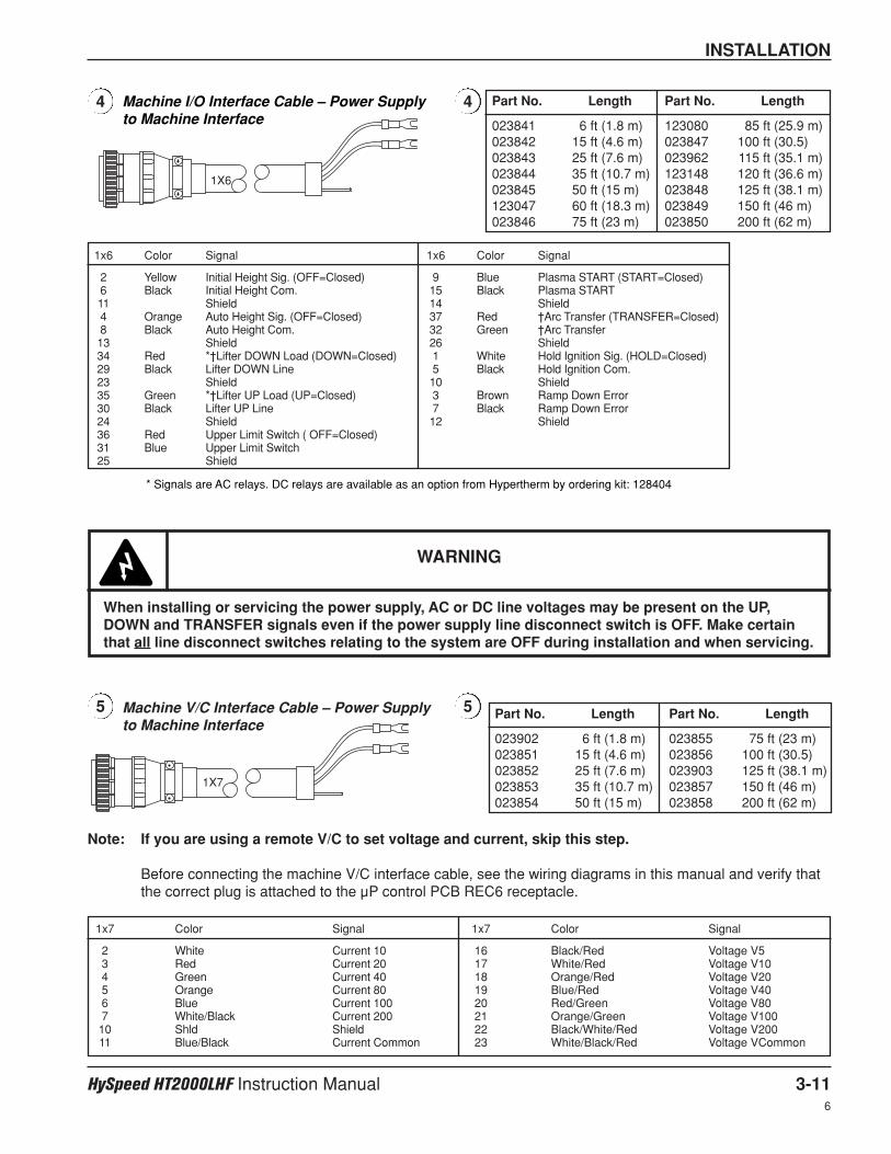
1X7
1X6
INSTALLATION
HySpeed HT2000LHF Instruction Manual 3-116
Machine V/C Interface Cable – Power Supplyto Machine Interface
1x6 Color Signal
2 Yellow Initial Height Sig. (OFF=Closed)6 Black Initial Height Com.11 Shield4 Orange Auto Height Sig. (OFF=Closed)8 Black Auto Height Com.13 Shield34 Red *†Lifter DOWN Load (DOWN=Closed)29 Black Lifter DOWN Line23 Shield35 Green *†Lifter UP Load (UP=Closed)30 Black Lifter UP Line24 Shield36 Red Upper Limit Switch ( OFF=Closed)31 Blue Upper Limit Switch25 Shield
1x6 Color Signal
9 Blue Plasma START (START=Closed)15 Black Plasma START14 Shield37 Red †Arc Transfer (TRANSFER=Closed)32 Green †Arc Transfer26 Shield1 White Hold Ignition Sig. (HOLD=Closed)5 Black Hold Ignition Com.10 Shield3 Brown Ramp Down Error7 Black Ramp Down Error12 Shield
1x7 Color Signal
2 White Current 103 Red Current 204 Green Current 405 Orange Current 806 Blue Current 1007 White/Black Current 20010 Shld Shield11 Blue/Black Current Common
1x7 Color Signal
16 Black/Red Voltage V517 White/Red Voltage V1018 Orange/Red Voltage V2019 Blue/Red Voltage V4020 Red/Green Voltage V8021 Orange/Green Voltage V10022 Black/White/Red Voltage V20023 White/Black/Red Voltage VCommon
Part No. Length
023841 6 ft (1.8 m)023842 15 ft (4.6 m)023843 25 ft (7.6 m)023844 35 ft (10.7 m)023845 50 ft (15 m)123047 60 ft (18.3 m)023846 75 ft (23 m)
Part No. Length
123080 85 ft (25.9 m)023847 100 ft (30.5)023962 115 ft (35.1 m)123148 120 ft (36.6 m)023848 125 ft (38.1 m)023849 150 ft (46 m)023850 200 ft (62 m)
4 4
5 5
* Signals are AC relays. DC relays are available as an option from Hypertherm by ordering kit: 128404
Machine I/O Interface Cable – Power Supplyto Machine Interface
Part No. Length
023902 6 ft (1.8 m)023851 15 ft (4.6 m)023852 25 ft (7.6 m)023853 35 ft (10.7 m)023854 50 ft (15 m)
Part No. Length
023855 75 ft (23 m)023856 100 ft (30.5)023903 125 ft (38.1 m)023857 150 ft (46 m)023858 200 ft (62 m)
WARNING
When installing or servicing the power supply, AC or DC line voltages may be present on the UP,DOWN and TRANSFER signals even if the power supply line disconnect switch is OFF. Make certainthat all line disconnect switches relating to the system are OFF during installation and when servicing.
Note: If you are using a remote V/C to set voltage and current, skip this step.
Before connecting the machine V/C interface cable, see the wiring diagrams in this manual and verify thatthe correct plug is attached to the µP control PCB REC6 receptacle.
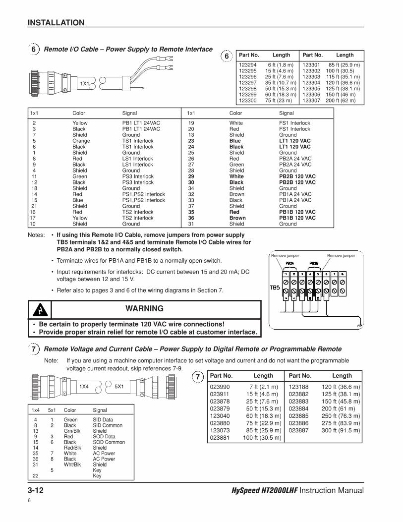
1X1
INSTALLATION
3-12 HySpeed HT2000LHF Instruction Manual6
Note: If you are using a machine computer interface to set voltage and current and do not want the programmablevoltage current readout, skip references 7-9.
Remote Voltage and Current Cable – Power Supply to Digital Remote or Programmable Remote
1x4 5x1 Color Signal
4 1 Green SID Data8 2 Black SID Common13 Grn/Blk Shield9 3 Red SOD Data15 6 Black SOD Common14 Red/Blk Shield35 7 White AC Power36 8 Black AC Power31 Wht/Blk Shield
5 Key22 Key
66
Notes: • If using this Remote I/O Cable, remove jumpers from power supply TB5 terminals 1&2 and 4&5 and terminate Remote I/O Cable wires forPB2A and PB2B to a normally closed switch.
• Terminate wires for PB1A and PB1B to a normally open switch.
• Input requirements for interlocks: DC current between 15 and 20 mA; DCvoltage between 12 and 15 V.
• Refer also to pages 3 and 6 of the wiring diagrams in Section 7.
Remove jumper Remove jumper
7
7
1X4 5X1
Part No. Length
123294 6 ft (1.8 m)123295 15 ft (4.6 m)123296 25 ft (7.6 m)123297 35 ft (10.7 m)123298 50 ft (15.3 m)123299 60 ft (18.3 m)123300 75 ft (23 m)
Part No. Length
123301 85 ft (25.9 m)123302 100 ft (30.5)123303 115 ft (35.1 m)123304 120 ft (36.6 m)123305 125 ft (38.1 m)123306 150 ft (46 m)123307 200 ft (62 m)
Remote I/O Cable – Power Supply to Remote Interface
1x1 Color Signal
19 White FS1 Interlock20 Red FS1 Interlock13 Shield Ground23 Blue LT1 120 VAC24 Black LT1 120 VAC25 Shield Ground26 Red PB2A 24 VAC27 Green PB2A 24 VAC28 Shield Ground29 White PB2B 120 VAC30 Black PB2B 120 VAC34 Shield Ground32 Brown PB1A 24 VAC33 Black PB1A 24 VAC37 Shield Ground35 Red PB1B 120 VAC36 Brown PB1B 120 VAC31 Shield Ground
1x1 Color Signal
2 Yellow PB1 LT1 24VAC3 Black PB1 LT1 24VAC7 Shield Ground5 Orange TS1 Interlock6 Black TS1 Interlock1 Shield Ground8 Red LS1 Interlock9 Black LS1 Interlock4 Shield Ground11 Green PS3 Interlock12 Black PS3 Interlock18 Shield Ground14 Red PS1,PS2 Interlock15 Blue PS1,PS2 Interlock21 Shield Ground
16 Red TS2 Interlock17 Yellow TS2 Interlock10 Shield Ground
Part No. Length
023990 7 ft (2.1 m)023911 15 ft (4.6 m)023878 25 ft (7.6 m)023879 50 ft (15.3 m)123040 60 ft (18.3 m)023880 75 ft (22.9 m)123073 85 ft (25.9 m)023881 100 ft (30.5 m)
Part No. Length
123188 120 ft (36.6 m)023882 125 ft (38.1 m)023883 150 ft (45.8 m)023884 200 ft (61 m)023885 250 ft (76.3 m)023886 275 ft (83.9 m)023887 300 ft (91.5 m)
WARNING
• Be certain to properly terminate 120 VAC wire connections! • Provide proper strain relief for remote I/O cable at customer interface.

1X10
INSTALLATION
HySpeed HT2000LHF Instruction Manual 3-136
Programmable Remote Voltage and Current Cable – Power Supply to Programmable Remote
Note: If you are using the digital remote to set voltage and current, skip this reference.
8
81X5 5X2
1X7 15X1
Current Control Cable – Power Supply to Remote Current Control
Note: If you are using the digital remote, programmable remote or machine computer to set current, skipthis reference.
9
9
Water Muffler Pump Cable – Power Supply to Water Muffler Pump
See water muffler instruction manual 802050 to connect cable to pump motor, and to make remaining watermuffler connections. The water muffler cannot be used with the stainless steel torch.
10
10
1x5 5x2 Color Signal
10 10 Black/Green Voltage 2011 11 Black/Orange Voltage 4012 12 Black/Red Voltage 8013 13 White/Green Voltage 10014 14 White/Red Voltage 20015 15 Black/White Spare16 16 Shld Shield
1x5 5x2 Color Signal
1 1 Black Current 202 2 Blue Current 403 3 Green Current 804 4 White Current 1005 5 Orange Current 2007 7 White/Black Common8 8 White/Blue Voltage 59 9 Black/Blue Voltage 10
Part No. Length
023834 15 ft (4.6 m)023835 25 ft (7.6 m)023836 50 ft (15.3 m)023837 75 ft (22.9 m)023838 100 ft (30.5 m)
Part No. Length
023898 125 ft (38.1 m)023839 150 ft (45.8 m)023840 200 ft (61 m)023899 250 ft (76.3 m)023900 275 ft (83.9 m)023901 300 ft (91.5 m)
Part No. Length
123150 10 ft (3 m)023871 25 ft (7.6 m)023872 38 ft (11.6 m)023873 50 ft (15 m)023874 75 ft (23 m)023875 100 ft (30.5 m)123068 110 ft (33.6 m)123277 120 ft (36.6 m)123088 125 ft (38.1 m)023876 150 ft (46 m)123032 170 ft (51.9 m)023877 200 ft (61 m)
Part No. Length
023866 50 ft (15 m)023867 75 ft (23 m)023868 100 ft (30.5)
1X7 15X1 Color Current Signal (I)
2 8 Black I-103 7 White I-204 10 Black I-405 9 Green I-806 15 Black I-1007 16 Red I-20011 3 I-Com
From 1X10 Color To WM Pump Contactor
2 Black Coil4 White AC Neut.3 Green Ground
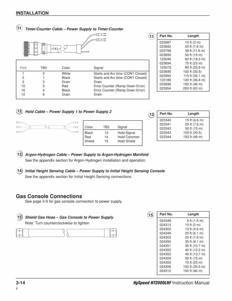
Gas Console ConnectionsSee page 3-9 for gas console connection to power supply.
Argon-Hydrogen Cable – Power Supply to Argon-Hydrogen Manifold
See the appendix section for Argon-Hydrogen installation and operation.
INSTALLATION
3-14 HySpeed HT2000LHF Instruction Manual6
11X1
Hold Cable – Power Supply 1 to Power Supply 2
Color TB3 Signal
Black 13 Hold SignalRed 14 Hold CommonShield 15 Hold Shield
Part No. Length
023340 15 ft (4.6 m)023341 25 ft (7.6 m)023342 50 ft (15 m)023343 100 ft (30.5)023344 150 ft (46 m)
12
13
Initial Height Sensing Cable – Power Supply to Initial Height Sensing Console
See the appendix section for Initial Height Sensing connections.
14
Shield Gas Hose – Gas Console to Power Supply
Note: Turn counterclockwise to tighten
15 15
12
Part No. Length
024348 5 ft (1.5 m)024313 10 ft (3 m)024302 15 ft (4.6 m)024349 20 ft (6.1 m)024303 25 ft (7.6 m)024350 30 ft (9.1 m)024351 35 ft (10.7 m)024352 40 ft (12.2 m)024353 45 ft (13.7 m)024304 50 ft (15 m)024305 75 ft (23 m)024306 100 ft (30.5 m)024312 150 ft (46 m)
Timer/Counter Cable – Power Supply to Timer/Counter11
11 Part No. Length
023687 10 ft (3 m)023692 25 ft (7.6 m)023758 38 ft (11.6 m)023693 50 ft (15 m)123046 60 ft (18.3 m)023694 75 ft (23 m)123079 85 ft (25.9 m)023695 100 ft (30.5)023993 115 ft (35.1 m)123189 120 ft (36.6 m)023696 150 ft (46 m)023954 200 ft (62 m)
11x1 TB3 Color Signal
1 2 White Starts and Arc time (CON1 Closed)2 1 Black Starts and Arc time (CON1 Closed)3 3 Drain Drain15 5 Red Error Counter (Ramp Down Error)16 4 Black Error Counter (Ramp Down Error)12 6 Drain Drain

INSTALLATION
HySpeed HT2000LHF Instruction Manual 3-156
Shield Gas Sense Hose – Gas Console to Power Supply16 16 Part No. Length
024061 5 ft (1.5 m)024063 10 ft (3 m)024065 15 ft (4.6 m)024067 20 ft (6.1 m)024069 25 ft (7.6 m)024071 30 ft (9.1 m)024356 35 ft (10.7 m)024092 40 ft (12.2 m)024403 45 ft (13.7 m)024096 50 ft (15 m)024174 60 ft (18.3 m)024468 75 ft (23 m)024523 100 ft (30.5 m)
Shield Gas Supply Hose – Shield Supply to Gas Console
Any supply gases that will be used for the shield gas, attach tothe same point on the gas console.
17 17 Part No. Length
024043 4 ft (1.2 m)024341 10 ft (3 m)024200 15 ft (4.6 m)024342 20 ft (6 m)024133 25 ft (7.6 m)024448 35 ft (10.7 m)024407 45 ft (13.7 m)024012 50 ft (15 m)024472 60 ft (18.3 m)024147 75 ft (23 m)024486 85 ft (25.9 m)024115 100 ft (30 m)024452 110 ft (33.6 m)024449 115 ft (35.1 m)024515 120 ft (36.6 m)024395 125 ft (38.1 m)024119 150 ft (46 m)024480 170 ft (51.9 m)024184 180 ft (55 m)024123 200 ft (61 m)
Oxygen Plasma Supply Hose – Oxygen Supply to Gas Console
Note: If cutting with oxygen as the plasma gas, nitrogenmust also be connected to the gas console toachieve the proper oxygen/nitrogen mixtures in thepreflow and cut flow conditions.
18 18 Part No. Length
024204 15 ft (4.6 m)024205 25 ft (7.6 m)024155 50 ft (15 m)024398 75 ft (22.9 m)024487 85 ft (25.9 m)024206 100 ft (30 m)024481 110 ft (33.6 m)024450 115 ft (35.1 m)024516 120 ft (36.6 m)024490 125 ft (38.1 m)024159 150 ft (46 m)024470 180 ft (54.9 m)024333 200 ft (61 m)
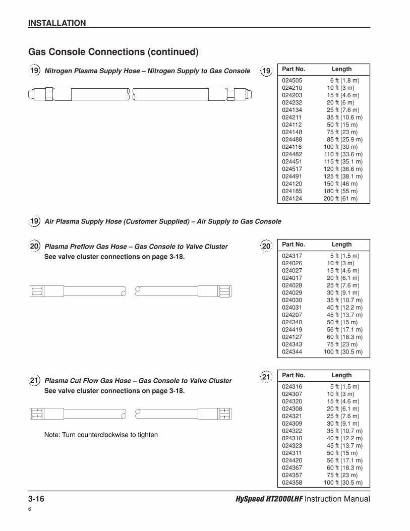
INSTALLATION
3-16 HySpeed HT2000LHF Instruction Manual6
Nitrogen Plasma Supply Hose – Nitrogen Supply to Gas Console19
Air Plasma Supply Hose (Customer Supplied) – Air Supply to Gas Console19
19 Part No. Length
024505 6 ft (1.8 m)024210 10 ft (3 m)024203 15 ft (4.6 m)024232 20 ft (6 m)024134 25 ft (7.6 m)024211 35 ft (10.6 m)024112 50 ft (15 m)024148 75 ft (23 m)024488 85 ft (25.9 m)024116 100 ft (30 m)024482 110 ft (33.6 m)024451 115 ft (35.1 m)024517 120 ft (36.6 m)024491 125 ft (38.1 m)024120 150 ft (46 m)024185 180 ft (55 m)024124 200 ft (61 m)
Plasma Preflow Gas Hose – Gas Console to Valve Cluster
See valve cluster connections on page 3-18.
20 20 Part No. Length
024317 5 ft (1.5 m)024026 10 ft (3 m)024027 15 ft (4.6 m)024017 20 ft (6.1 m)024028 25 ft (7.6 m)024029 30 ft (9.1 m)024030 35 ft (10.7 m)024031 40 ft (12.2 m)024207 45 ft (13.7 m)024340 50 ft (15 m)024419 56 ft (17.1 m)024127 60 ft (18.3 m)024343 75 ft (23 m)024344 100 ft (30.5 m)
Plasma Cut Flow Gas Hose – Gas Console to Valve Cluster
See valve cluster connections on page 3-18.
21 21 Part No. Length
024316 5 ft (1.5 m)024307 10 ft (3 m)024320 15 ft (4.6 m)024308 20 ft (6.1 m)024321 25 ft (7.6 m)024309 30 ft (9.1 m)024322 35 ft (10.7 m)024310 40 ft (12.2 m)024323 45 ft (13.7 m)024311 50 ft (15 m)024420 56 ft (17.1 m)024367 60 ft (18.3 m)024357 75 ft (23 m)024358 100 ft (30.5 m)
Gas Console Connections (continued)
Note: Turn counterclockwise to tighten
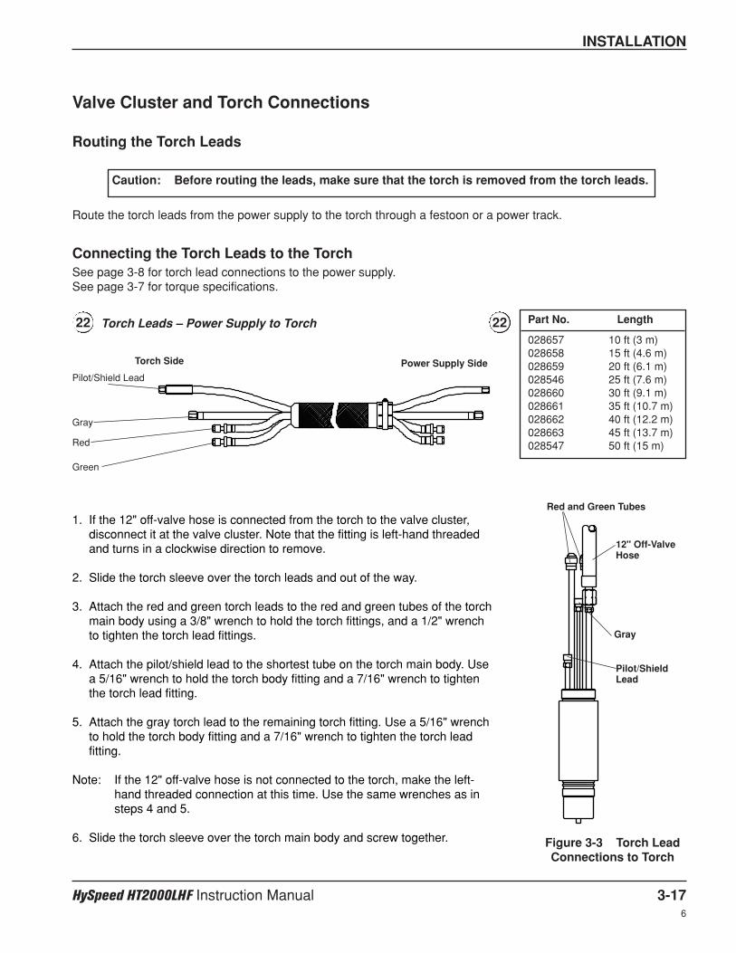
INSTALLATION
HySpeed HT2000LHF Instruction Manual 3-176
Valve Cluster and Torch Connections
Routing the Torch Leads
Caution: Before routing the leads, make sure that the torch is removed from the torch leads.
1. If the 12" off-valve hose is connected from the torch to the valve cluster,disconnect it at the valve cluster. Note that the fitting is left-hand threadedand turns in a clockwise direction to remove.
2. Slide the torch sleeve over the torch leads and out of the way.
3. Attach the red and green torch leads to the red and green tubes of the torchmain body using a 3/8" wrench to hold the torch fittings, and a 1/2" wrenchto tighten the torch lead fittings.
4. Attach the pilot/shield lead to the shortest tube on the torch main body. Usea 5/16" wrench to hold the torch body fitting and a 7/16" wrench to tightenthe torch lead fitting.
5. Attach the gray torch lead to the remaining torch fitting. Use a 5/16" wrenchto hold the torch body fitting and a 7/16" wrench to tighten the torch leadfitting.
Note: If the 12" off-valve hose is not connected to the torch, make the left-hand threaded connection at this time. Use the same wrenches as insteps 4 and 5.
6. Slide the torch sleeve over the torch main body and screw together.
Power Supply SideTorch Side
Pilot/Shield Lead
Gray
Red
Green
Figure 3-3 Torch LeadConnections to Torch
Red and Green Tubes
12" Off-ValveHose
Pilot/ShieldLead
Gray
Route the torch leads from the power supply to the torch through a festoon or a power track.
Connecting the Torch Leads to the TorchSee page 3-8 for torch lead connections to the power supply.See page 3-7 for torque specifications.
Torch Leads – Power Supply to Torch22 22 Part No. Length
028657 10 ft (3 m)028658 15 ft (4.6 m)028659 20 ft (6.1 m)028546 25 ft (7.6 m)028660 30 ft (9.1 m)028661 35 ft (10.7 m)028662 40 ft (12.2 m)028663 45 ft (13.7 m)028547 50 ft (15 m)
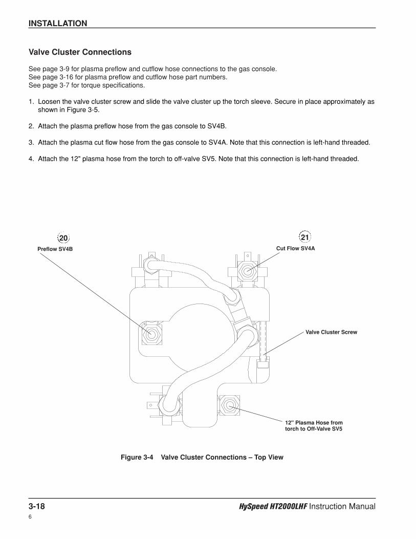
INSTALLATION
3-18 HySpeed HT2000LHF Instruction Manual6
Valve Cluster Connections
See page 3-9 for plasma preflow and cutflow hose connections to the gas console.See page 3-16 for plasma preflow and cutflow hose part numbers.See page 3-7 for torque specifications.
1. Loosen the valve cluster screw and slide the valve cluster up the torch sleeve. Secure in place approximately asshown in Figure 3-5.
2. Attach the plasma preflow hose from the gas console to SV4B.
3. Attach the plasma cut flow hose from the gas console to SV4A. Note that this connection is left-hand threaded.
4. Attach the 12" plasma hose from the torch to off-valve SV5. Note that this connection is left-hand threaded.
Figure 3-4 Valve Cluster Connections – Top View
20 21Preflow SV4B Cut Flow SV4A
Valve Cluster Screw
12" Plasma Hose fromtorch to Off-Valve SV5
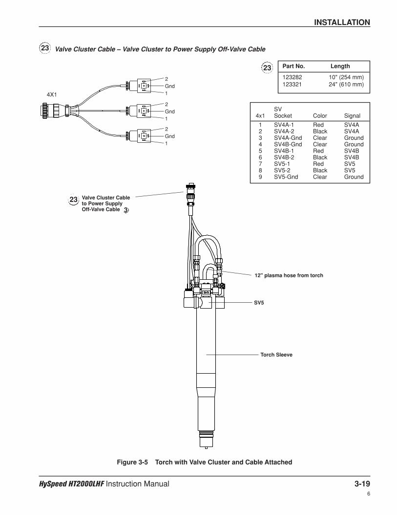
INSTALLATION
HySpeed HT2000LHF Instruction Manual 3-196
Figure 3-5 Torch with Valve Cluster and Cable Attached
23 Valve Cluster Cable to Power Supply Off-Valve Cable
12" plasma hose from torch
Torch Sleeve
SV5
Valve Cluster Cable – Valve Cluster to Power Supply Off-Valve Cable
SV4x1 Socket Color Signal
1 SV4A-1 Red SV4A2 SV4A-2 Black SV4A3 SV4A-Gnd Clear Ground4 SV4B-Gnd Clear Ground5 SV4B-1 Red SV4B6 SV4B-2 Black SV4B7 SV5-1 Red SV58 SV5-2 Black SV59 SV5-Gnd Clear Ground
23
4X1
2
1Gnd
2
1Gnd
2
1Gnd
3
23 Part No. Length
123282 10" (254 mm)123321 24" (610 mm)
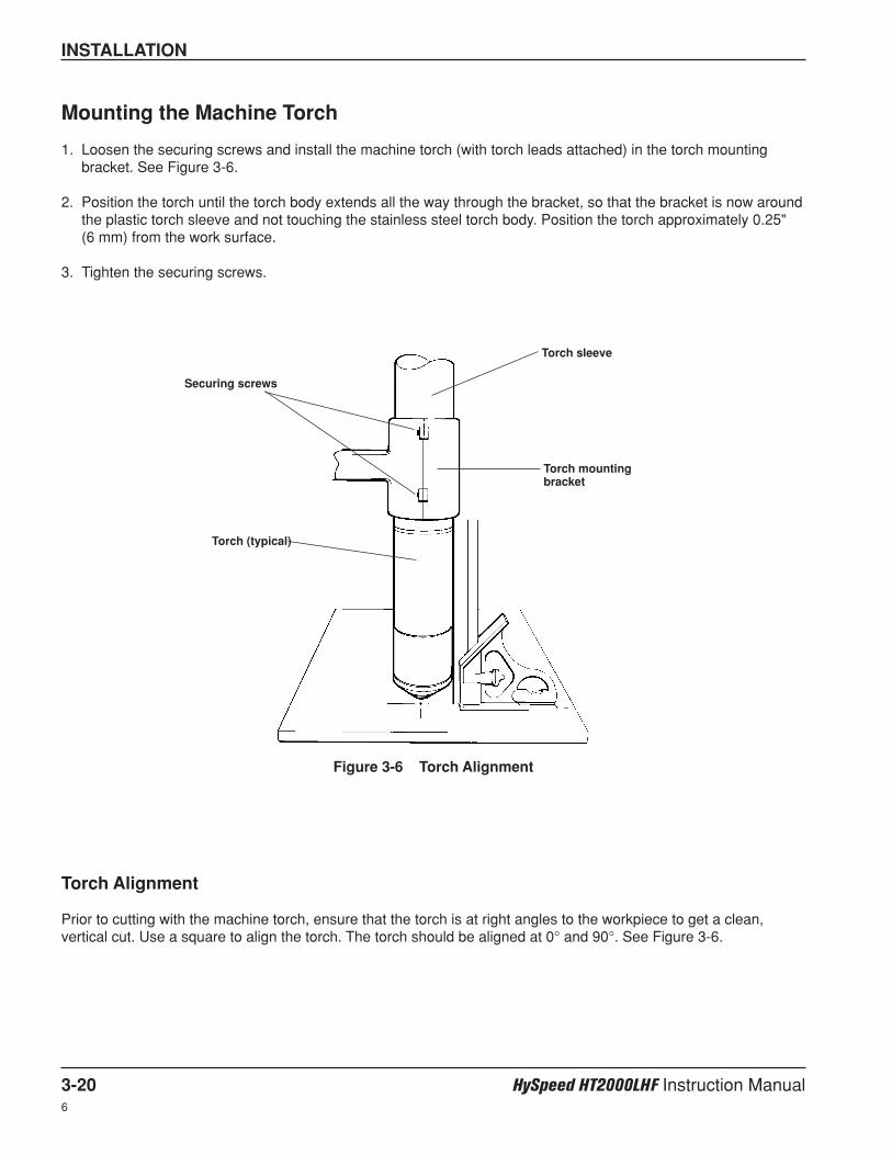
INSTALLATION
3-20 HySpeed HT2000LHF Instruction Manual6
Mounting the Machine Torch
1. Loosen the securing screws and install the machine torch (with torch leads attached) in the torch mountingbracket. See Figure 3-6.
2. Position the torch until the torch body extends all the way through the bracket, so that the bracket is now aroundthe plastic torch sleeve and not touching the stainless steel torch body. Position the torch approximately 0.25"(6 mm) from the work surface.
3. Tighten the securing screws.
Torch Alignment
Prior to cutting with the machine torch, ensure that the torch is at right angles to the workpiece to get a clean,vertical cut. Use a square to align the torch. The torch should be aligned at 0° and 90°. See Figure 3-6.
Securing screws
Torch sleeve
Torch mounting bracket
Figure 3-6 Torch Alignment
Torch (typical)
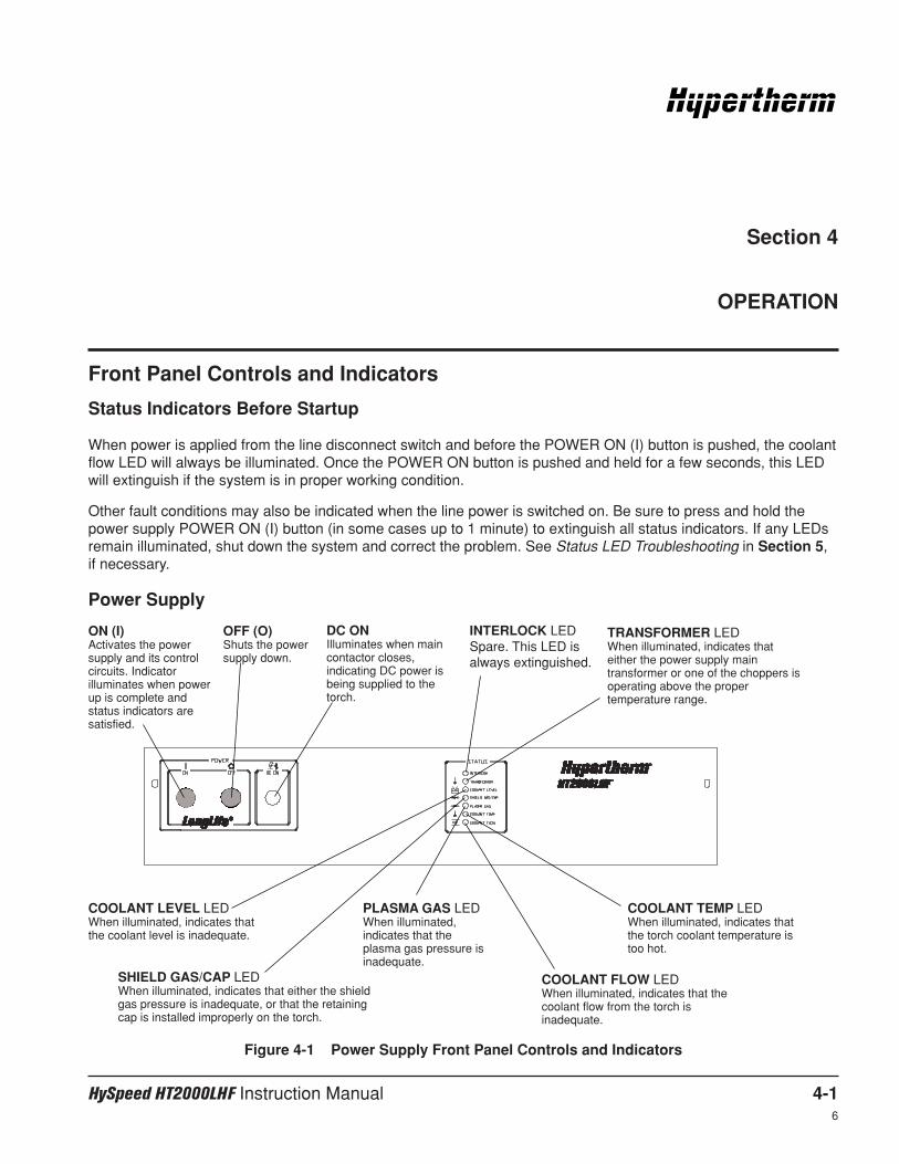
HySpeed HT2000LHF Instruction Manual 4-16
Front Panel Controls and Indicators
Status Indicators Before Startup
When power is applied from the line disconnect switch and before the POWER ON (I) button is pushed, the coolantflow LED will always be illuminated. Once the POWER ON button is pushed and held for a few seconds, this LEDwill extinguish if the system is in proper working condition.
Other fault conditions may also be indicated when the line power is switched on. Be sure to press and hold thepower supply POWER ON (I) button (in some cases up to 1 minute) to extinguish all status indicators. If any LEDsremain illuminated, shut down the system and correct the problem. See Status LED Troubleshooting in Section 5,if necessary.
Figure 4-1 Power Supply Front Panel Controls and Indicators
Section 4
OPERATION
ON (I)Activates the powersupply and its controlcircuits. Indicatorilluminates when powerup is complete andstatus indicators aresatisfied.
OFF (O)Shuts the powersupply down.
DC ONIlluminates when maincontactor closes,indicating DC power isbeing supplied to thetorch.
INTERLOCK LEDSpare. This LED isalways extinguished.
TRANSFORMER LEDWhen illuminated, indicates thateither the power supply maintransformer or one of the choppers isoperating above the propertemperature range.
COOLANT LEVEL LEDWhen illuminated, indicates thatthe coolant level is inadequate.
SHIELD GAS/CAP LEDWhen illuminated, indicates that either the shieldgas pressure is inadequate, or that the retainingcap is installed improperly on the torch.
PLASMA GAS LEDWhen illuminated,indicates that theplasma gas pressure isinadequate.
COOLANT TEMP LEDWhen illuminated, indicates thatthe torch coolant temperature istoo hot.
COOLANT FLOW LEDWhen illuminated, indicates that thecoolant flow from the torch isinadequate.
Power Supply
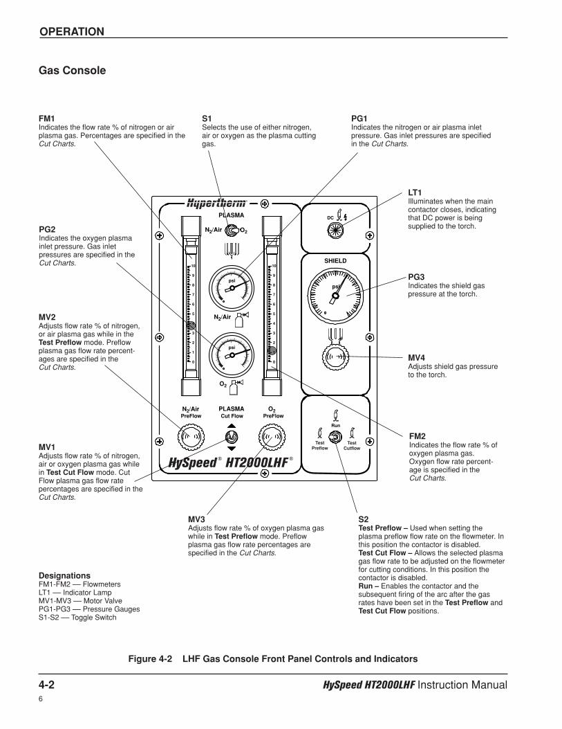
PLASMA
N2/Air O2
SHIELD
N2/Air
psi
psipsi
DC
N2/Air
O2
O2PLASMACut Flow PreFlowPreFlow
Run
10
9
8
7
6
5
4
3
2
1
0
10
9
8
7
6
5
4
3
2
1
0
TestPreflow
TestCutflow
HySpeed ® HT2000LHF
®
OPERATION
4-2 HySpeed HT2000LHF Instruction Manual6
Gas Console
Figure 4-2 LHF Gas Console Front Panel Controls and Indicators
S2Test Preflow – Used when setting theplasma preflow flow rate on the flowmeter. Inthis position the contactor is disabled.Test Cut Flow – Allows the selected plasmagas flow rate to be adjusted on the flowmeterfor cutting conditions. In this position thecontactor is disabled.Run – Enables the contactor and thesubsequent firing of the arc after the gasrates have been set in the Test Preflow andTest Cut Flow positions.
LT1Illuminates when the maincontactor closes, indicatingthat DC power is beingsupplied to the torch.
FM1Indicates the flow rate % of nitrogen or airplasma gas. Percentages are specified in theCut Charts.
PG1Indicates the nitrogen or air plasma inletpressure. Gas inlet pressures are specifiedin the Cut Charts.
FM2Indicates the flow rate % ofoxygen plasma gas.Oxygen flow rate percent-age is specified in the Cut Charts.
PG2Indicates the oxygen plasmainlet pressure. Gas inletpressures are specified in theCut Charts.
MV1Adjusts flow rate % of nitrogen,air or oxygen plasma gas whilein Test Cut Flow mode. CutFlow plasma gas flow ratepercentages are specified in theCut Charts.
S1Selects the use of either nitrogen,air or oxygen as the plasma cuttinggas.
MV2Adjusts flow rate % of nitrogen,or air plasma gas while in theTest Preflow mode. Preflowplasma gas flow rate percent-ages are specified in the Cut Charts.
MV3Adjusts flow rate % of oxygen plasma gaswhile in Test Preflow mode. Preflowplasma gas flow rate percentages arespecified in the Cut Charts.
PG3Indicates the shield gaspressure at the torch.
MV4Adjusts shield gas pressureto the torch.
DesignationsFM1-FM2 –– FlowmetersLT1 –– Indicator LampMV1-MV3 –– Motor ValvePG1-PG3 –– Pressure GaugesS1-S2 –– Toggle Switch
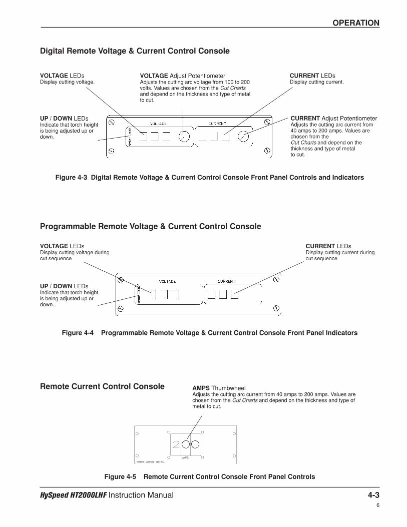
OPERATION
HySpeed HT2000LHF Instruction Manual 4-36
VOLTAGE Adjust PotentiometerAdjusts the cutting arc voltage from 100 to 200volts. Values are chosen from the Cut Chartsand depend on the thickness and type of metalto cut.
CURRENT Adjust PotentiometerAdjusts the cutting arc current from40 amps to 200 amps. Values arechosen from the Cut Charts and depend on thethickness and type of metal to cut.
VOLTAGE LEDsDisplay cutting voltage.
UP / DOWN LEDsIndicate that torch heightis being adjusted up ordown.
CURRENT LEDsDisplay cutting current.
Figure 4-3 Digital Remote Voltage & Current Control Console Front Panel Controls and Indicators
VOLTAGE LEDsDisplay cutting voltage duringcut sequence
CURRENT LEDsDisplay cutting current duringcut sequence
UP / DOWN LEDsIndicate that torch heightis being adjusted up ordown.
Figure 4-4 Programmable Remote Voltage & Current Control Console Front Panel Indicators
Digital Remote Voltage & Current Control Console
Programmable Remote Voltage & Current Control Console
Remote Current Control Console AMPS ThumbwheelAdjusts the cutting arc current from 40 amps to 200 amps. Values arechosen from the Cut Charts and depend on the thickness and type ofmetal to cut.
Figure 4-5 Remote Current Control Console Front Panel Controls
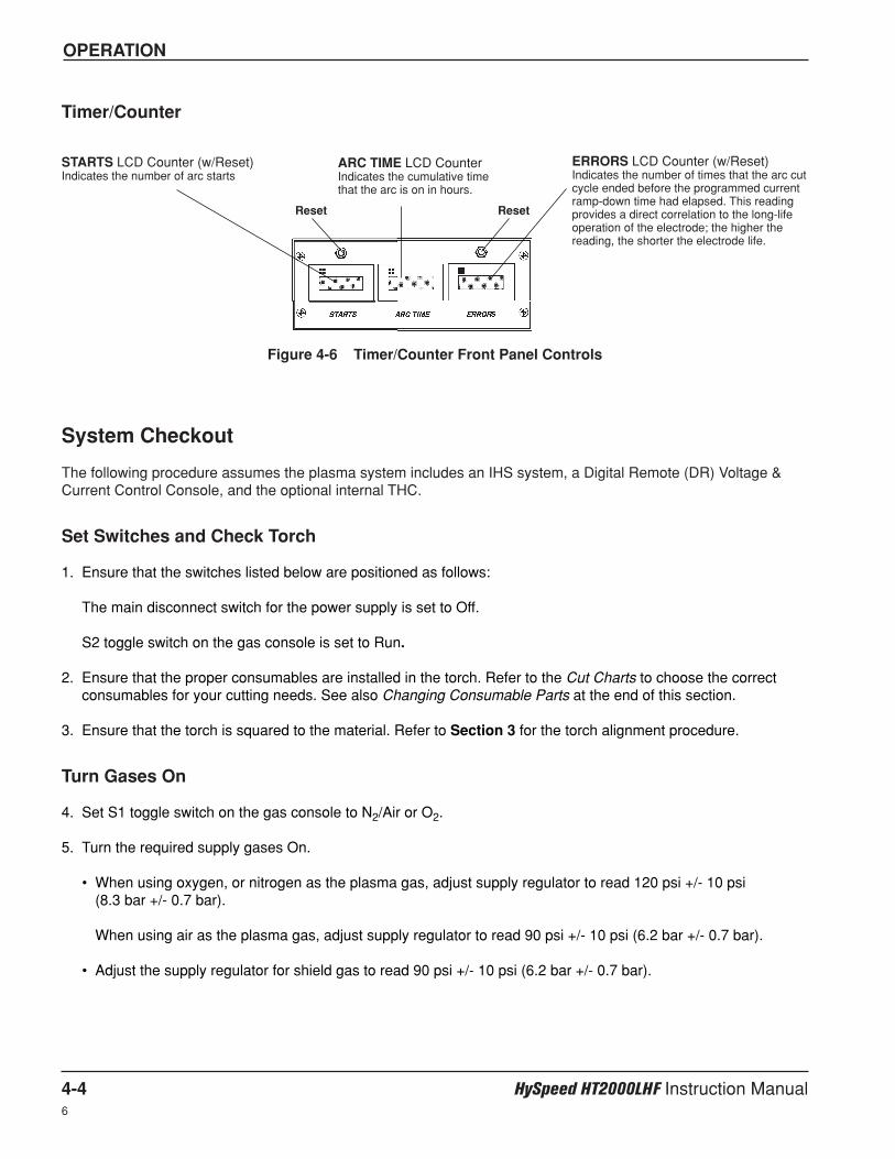
OPERATION
4-4 HySpeed HT2000LHF Instruction Manual6
Timer/Counter
STARTS LCD Counter (w/Reset)Indicates the number of arc starts
ERRORS LCD Counter (w/Reset)Indicates the number of times that the arc cutcycle ended before the programmed currentramp-down time had elapsed. This readingprovides a direct correlation to the long-lifeoperation of the electrode; the higher thereading, the shorter the electrode life.
Reset
ARC TIME LCD CounterIndicates the cumulative timethat the arc is on in hours.
Reset
Figure 4-6 Timer/Counter Front Panel Controls
System Checkout
The following procedure assumes the plasma system includes an IHS system, a Digital Remote (DR) Voltage &Current Control Console, and the optional internal THC.
Set Switches and Check Torch
1. Ensure that the switches listed below are positioned as follows:
The main disconnect switch for the power supply is set to Off.
S2 toggle switch on the gas console is set to Run.
2. Ensure that the proper consumables are installed in the torch. Refer to the Cut Charts to choose the correctconsumables for your cutting needs. See also Changing Consumable Parts at the end of this section.
3. Ensure that the torch is squared to the material. Refer to Section 3 for the torch alignment procedure.
Turn Gases On
4. Set S1 toggle switch on the gas console to N2/Air or O2.
5. Turn the required supply gases On.
• When using oxygen, or nitrogen as the plasma gas, adjust supply regulator to read 120 psi +/- 10 psi (8.3 bar +/- 0.7 bar).
When using air as the plasma gas, adjust supply regulator to read 90 psi +/- 10 psi (6.2 bar +/- 0.7 bar).
• Adjust the supply regulator for shield gas to read 90 psi +/- 10 psi (6.2 bar +/- 0.7 bar).
OPERATION
HySpeed HT2000LHF Instruction Manual 4-56
Turn Power Supply On and Adjust Voltage/Current
6. Set the main disconnect switch for the power supply to the On position. See Status Indicators Before Startup.Depress the POWER ON (I) button on the power supply. Ensure that the green POWER ON indicator on thepower supply illuminates.
7. Set the VOLTAGE and CURRENT on the Digital Remote. Select the arc current and arc voltage from the Cut Charts for the type and thickness of metal to test cut.
Adjust Preflow Gases
8. Set S2 toggle switch to Test Preflow . Verify that the plasma gas pressure gauges on the gas console bothread 120 psi (8.3 bar).
9. Look at FM1 and/or FM2 and set the Preflow plasma gas flow rate. Refer to the Cut Charts for flow ratepercentage.
10. Look at PG3 on the gas console, and set the Shield gas flow rate. Refer to the Cut Charts for flow ratepercentage.
Adjust Cut Flow Gases and Check Initial Height Sensing (IHS)
11. Set S2 toggle switch to Test Cut Flow.
12. Look at FM1 and/or FM2 and set the Cut Flow plasma gas flow rate. Refer to the Cut Charts for flow ratepercentage.
13. Set S2 to Run after setting the preflow and plasma flow rates.
14. Check the pilot arc operation by positioning the torch a minimum of 3 inches (75 mm) above the work.
15. Depress the START button. After 2 seconds of gas preflow, the primary contactor will close and the pilot arcwill start. The pilot arc should emit a steady, hissing sound and a cone of light should appear at the face of thetorch nozzle. The pilot arc will continue for approximately 300ms (O2) and 600 ms (Air/N2) and then extinguishautomatically.
16. Place the workpiece on the work table to make a test pierce. With manual starting, no machine motion willoccur.
Note: The cutting machine must retract the torch at least 1 inch (25.4 mm) from the work before the startcycle, or probes may hit the workpiece when the START button is depressed.
17. Depress the START button. The IHS probes will immediately descend and approximately 0.5 seconds later, thetorch will move toward the workpiece. The DOWN indicator lamp on the Digital Remote should be illuminated.When the torch nears the workpiece, the probes will inductively detect the work surface and the down motionshould stop. The DOWN indicator lamp on the Digital Remote will extinguish and the probes will retract.
At this point, depress the STOP button and disable the IHS system. You are now ready for the Final TorchAdjustment.
OPERATION
4-6 HySpeed HT2000LHF Instruction Manual6
Final Torch Adjustment
18. Make a reference mark on the top and bottom of the torch sleeve where it meets the torch mounting bracket.
19. Loosen the securing screw on the torch mounting bracket and position the torch higher in the mounting bracketuntil the arc will not transfer when the START button is depressed.
20. Slowly lower the torch in 1/16" (1.6 mm) increments until the arc transfers after the START button isdepressed. Tighten the securing screw at this position.
21. Enable the IHS system and press the START button. Once the arc transfers and the machine delay time haselapsed, the metal should be pierced. Press the STOP button to terminate the plasma arc. Observe that theUP indicator illuminates and the torch retracts to the upper limit switch.
22. Disable the IHS system.
Check Torch Height Control (THC) and Digital Remote Voltage & Current Console
23. Position the workpiece on the work table with one end higher than the other end to check the auto height (torchheight control) mode. Position the torch at the highest point on the workpiece. Program a square cut patterninto the controller. (See controller instruction manual.)
24. Enable the Auto Height Control for the THC.
25. Manually lower the torch to approximately .25 inches (6 mm) above the workpiece.
26. Start the arc transfer from the controller.
27. When the arc transfers and the machine delay time has elapsed, the workpiece should be pierced andmachine motion will start. As the torch travels from a high point to a low point on the workpiece, note that thetorch stand-off distance from the workpiece should remain constant, and that the DOWN indicator illuminateson the Digital Remote.
As the torch travels from a low point to a high point on the workpiece, note that the torch stand-off distancefrom the workpiece should remain constant and that the UP indicator illuminates on the Digital Remote.
As the torch makes a corner cut, the machine motion speed should remain constant and the UP and DOWNindicators do not illuminate. Machine motion and plasma arc will automatically stop when the cut is complete.
The system is now operational.
If the system does not function as outlined in this procedure, recheck the installation requirements and directions inthis manual. If all installation directives have been followed and you are still experiencing difficulty with the system,call the Hypertherm Technical Service number listed in the front of this manual.
OPERATION
HySpeed HT2000LHF Instruction Manual 4-710
WARNING
Before operating this system, you must read the Safety section thoroughly! Turn main disconnectswitch to the power supply OFF before proceeding with the following steps.
Daily Startup
Prior to startup, ensure that your cutting environment and that your clothing meet the safety requirements outlinedin the Safety section of this manual.
Note: For operation with argon-hydrogen manifold, see the appendix section of this manual.
Check Torch
1. Remove the consumables from the torch and check for worn or damaged parts. Always place theconsumables on a clean, dry, oil-free surface after removing. Dirty consumables can cause the torch tomalfunction.
• Check the pit depth of the electrode using the electrode gauge assembly. A standard electrode should bereplaced when the depth exceeds .044 inch (1.1 mm). The SilverPlus electrode may be replaced when the pitdepth exceeds approximately double the recommended depth of a standard electrode.
• Wipe the current ring in the torch with a clean paper towel or cotton swab (see Figure 4-7).
• Refer to the Cut Charts to choose the correct consumables for your cutting needs.
2. Replace consumable parts. Refer to Changing Consumable Parts later in this section for detailed information onreplacing consumables.
3. Ensure that the torch is perpendicular to the material. Refer to Section 3 for the torch alignment procedure.
Noise Levels (Decibels)
Decibels experienced by an operator standing 1 meter from the torch while cutting at 50 Amps, with the torch 1/2”above water = 94.7 dbs.
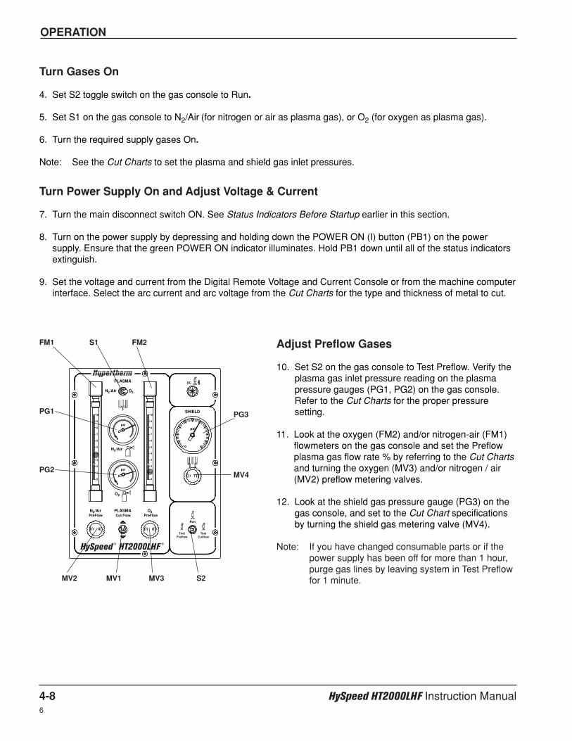
OPERATION
4-8 HySpeed HT2000LHF Instruction Manual6
Turn Gases On
4. Set S2 toggle switch on the gas console to Run.
5. Set S1 on the gas console to N2/Air (for nitrogen or air as plasma gas), or O2 (for oxygen as plasma gas).
6. Turn the required supply gases On.
Note: See the Cut Charts to set the plasma and shield gas inlet pressures.
Turn Power Supply On and Adjust Voltage & Current
7. Turn the main disconnect switch ON. See Status Indicators Before Startup earlier in this section.
8. Turn on the power supply by depressing and holding down the POWER ON (I) button (PB1) on the powersupply. Ensure that the green POWER ON indicator illuminates. Hold PB1 down until all of the status indicatorsextinguish.
9. Set the voltage and current from the Digital Remote Voltage and Current Console or from the machine computerinterface. Select the arc current and arc voltage from the Cut Charts for the type and thickness of metal to cut.
PLASMA
N2/Air O2
SHIELD
N2/Air
psi
psipsi
DC
N2/Air
O2
O2PLASMACut Flow PreFlowPreFlow
Run
10
9
8
7
6
5
4
3
2
1
0
10
9
8
7
6
5
4
3
2
1
0
TestPreflow
TestCutflow
HySpeed ® HT2000LHF
®
Adjust Preflow Gases
10. Set S2 on the gas console to Test Preflow. Verify theplasma gas inlet pressure reading on the plasmapressure gauges (PG1, PG2) on the gas console.Refer to the Cut Charts for the proper pressuresetting.
11. Look at the oxygen (FM2) and/or nitrogen-air (FM1)flowmeters on the gas console and set the Preflowplasma gas flow rate % by referring to the Cut Chartsand turning the oxygen (MV3) and/or nitrogen / air(MV2) preflow metering valves.
12. Look at the shield gas pressure gauge (PG3) on thegas console, and set to the Cut Chart specificationsby turning the shield gas metering valve (MV4).
Note: If you have changed consumable parts or if thepower supply has been off for more than 1 hour,purge gas lines by leaving system in Test Preflowfor 1 minute.
FM1
PG1
PG2
PG3
MV4
S1 FM2
MV2 MV1 MV3 S2
OPERATION
HySpeed HT2000LHF Instruction Manual 4-96
Adjust Cut Flow Gases and Prepare for Cutting
13. Set S2 on the gas console to Test Cut Flow.
14. Look at the oxygen (FM2) and/or nitrogen / air (FM1) flowmeters on the gas console and set the Cut Flowplasma gas flow rate % by referring to the Cut Charts and adjusting the Plasma Cut Flow metering valve(MV1).
Note: If you have changed consumable parts or if the power supply has been off for more than 1 hour, purge gaslines by leaving the system in Test Cut Flow for one minute.
15. Set S2 to Run after the test preflow and test operate flow rates have been set.
The system is now ready for operation.
Common Cutting Faults
• Torch pilot arc will initiate, but will not transfer. Causes can be:
1. Work cable connection on the cutting table is not making good contact.
2. Malfunction in the system. See Section 5.
• The workpiece is not totally penetrated, and there is excessive sparking on top of the workpiece. Causes can be:
1. Current is set too low (check Cut Chart information).
2. Cut speed is too high (check Cut Chart information).
3. Torch parts are worn (see Changing Consumable Parts).
4. Metal being cut is too thick.
• Dross forms on the bottom of the cut. Causes can be:
1. Cutting speed is too slow or too fast (check Cut Chart information).
2. Arc current is set too low (check Cut Chart information).
3. Torch parts are worn (see Changing Consumable Parts).
• Cut angle is not square. Causes can be:
1. Wrong direction of machine travel.
High quality side is on the right with respect to the forward motion of the torch.
2. Torch-to-work distance is not correct (check Cut Chart information).
3. Cutting speed is not correct (check Cut Chart information).
4. Arc current is not correct (check Cut Chart information).
OPERATION
4-10 HySpeed HT2000LHF Instruction Manual7
5. Damaged consumable parts (see Changing Consumable Parts ).
• Short consumable life. Causes can be:
1. Arc current, arc voltage, travel speed, motion delay, gas flow rates, or initial torch height not set as specified inthe Cut Charts.
2. Attempting to cut highly magnetic metal plate (some metals such as armor plate with a high nickel content)will shorten consumable life. Long consumable life is difficult to achieve when cutting plate that is magnetizedor becomes magnetized easily.
3. Not beginning or ending the cut on the plate surface. To achieve consumable long life, all cuts must beginand end on the plate surface.
Also see Cutting Techniques later in this section for methods to improve cutting performance.
Technical Questions
If your system does not function correctly:
1. Recheck all pre-installation and installation requirements and connections.
2. If you are unable to solve the problem, call your distributor. He will be able to help you, or refer you to anauthorized Hypertherm repair facility.
3. If you need assistance, call the Hypertherm Technical Service number listed in the front of this manual.
Cut Charts
The Cut Charts on the following pages provide the necessary information for the operator using the system to besuccessful in plasma arc cutting. The system provides a wide travel speed operating window: usually ± 10 ipm(± 254 mm/min) on most materials. The data listed in the charts are for making drop cuts with minimal dross.
Caution: Before cutting, check all settings and adjustments and check fordamaged torch parts and worn consumable parts.
Conversions1 inch = 25.4 mm; 1 scfh = 28.316 liter/hour; 1 psi = .0689 bar = 6.895 KPa
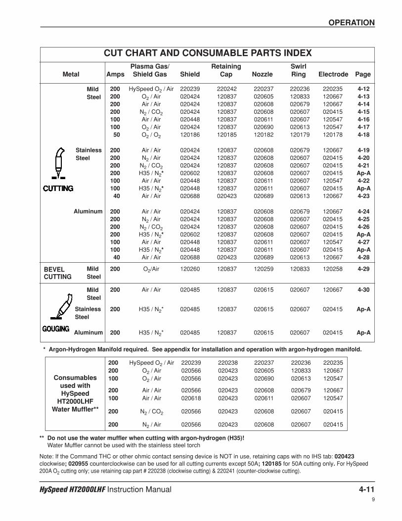
OPERATION
HySpeed HT2000LHF Instruction Manual 4-119
CUT CHART AND CONSUMABLE PARTS INDEXPlasma Gas/ Retaining Swirl
Metal Amps Shield Gas Shield Cap Nozzle Ring Electrode Page
MildSteel
MildSteel
MildSteel
StainlessSteel
StainlessSteel
Aluminum
Aluminum
200 HySpeed O2 / Air 220239 220242 220237 220236 220235 4-12200 O2 / Air 020424 120837 020605 120833 120667 4-13200 Air / Air 020424 120837 020608 020679 120667 4-14200 N2 / CO2 020424 120837 020608 020607 020415 4-15100 Air / Air 020448 120837 020611 020607 120547 4-16100 O2 / Air 020424 120837 020690 020613 120547 4-1750 O2 / O2 120186 120185 120182 120179 120178 4-18
200 Air / Air 020424 120837 020608 020679 120667 4-19200 N2 / Air 020424 120837 020608 020607 020415 4-20200 N2 / CO2 020424 120837 020608 020607 020415 4-21200 H35 / N2* 020602 120837 020608 020607 020415 Ap-A100 Air / Air 020448 120837 020611 020607 120547 4-22100 H35 / N2* 020448 120837 020611 020607 020415 Ap-A40 Air / Air 020688 020423 020689 020613 120667 4-23
200 Air / Air 020424 120837 020608 020679 120667 4-24200 N2 / Air 020424 120837 020608 020607 020415 4-25200 N2 / CO2 020424 120837 020608 020607 020415 4-26200 H35 / N2* 020602 120837 020608 020607 020415 Ap-A100 Air / Air 020448 120837 020611 020607 120547 4-27100 H35 / N2* 020448 120837 020611 020607 020415 Ap-A40 Air / Air 020688 020423 020689 020613 120667 4-28
200 O2/Air 120260 120837 120259 120833 120258 4-29
200 Air / Air 020485 120837 020615 020607 120667 4-30
200 H35 / N2* 020485 120837 020615 020607 020415 Ap-A
200 H35 / N2* 020485 120837 020615 020607 020415 Ap-A
BEVELCUTTING
* Argon-Hydrogen Manifold required. See appendix for installation and operation with argon-hydrogen manifold.
** Do not use the water muffler when cutting with argon-hydrogen (H35)!Water Muffler cannot be used with the stainless steel torch
Note: If the Command THC or other ohmic contact sensing device is NOT in use, retaining caps with no IHS tab: 020423clockwise; 020955 counterclockwise can be used for all cutting currents except 50A; 120185 for 50A cutting only. For HySpeed200A O2 cutting only; use retaining cap part # 220238 (clockwise cutting) & 220241 (counter-clockwise cutting).
200 HySpeed O2 / Air 220239 220238 220237 220236 220235200 O2 / Air 020566 020423 020605 120833 120667100 O2 / Air 020566 020423 020690 020613 120547
200 Air / Air 020566 020423 020608 020679 120667100 Air / Air 020618 020423 020611 020607 120547
200 N2 / CO2 020566 020423 020608 020607 020415
200 N2 / Air 020566 020423 020608 020607 020415
Consumablesused withHySpeed
HT2000LHFWater Muffler**
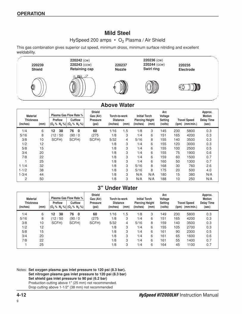
9
OPERATION
4-12 HySpeed HT2000LHF Instruction Manual
Shield Arc Approx.Material Plasma Gas Flow Rate % Gas (Air) Torch-to-work Initial Torch Voltage Motion
Thickness Preflow Cutflow Pressure Distance Piercing Height Setting Travel Speed Delay Time(inches) (mm) (O2 % N2 %) (O2 % N2 %) (psi) (inches) (mm) (inches) (mm) (volts) (ipm) (mm/min.) (sec)
Shield Arc Approx.Material Plasma Gas Flow Rate % Gas (Air) Torch-to-work Initial Torch Voltage Motion
Thickness Preflow Cutflow Pressure Distance Piercing Height Setting Travel Speed Delay Time(inches) (mm) (O2 % N2 %) (O2 % N2 %) (psi) (inches) (mm) (inches) (mm) (volts) (ipm) (mm/min.) (sec)
1/4 6 12 38 76 0 60 1/16 1.5 1/8 3 145 230 5800 0.35/16 8 (12 / 50 (90 / 0 (275 1/8 3 1/4 6 151 165 4200 0.33/8 10 SCFH) SCFH) SCFH) 5/32 4 5/16 8 155 140 3500 0.31/2 12 1/8 3 1/4 6 155 120 3000 0.35/8 15 1/8 3 1/4 6 155 100 2500 0.53/4 20 1/8 3 1/4 6 155 75 1900 0.67/8 22 1/8 3 1/4 6 159 60 1500 0.7
1 25 1/8 3 1/4 6 160 50 1300 0.71 1/4 32 1/8 3 5/16 8 168 30 760 2.61-1/2 38 1/8 3 5/16 8 175 20 500 4.01-3/4 44 1/8 3 N/A N/A 180 15 380 N/A
2 50 1/8 3 N/A N/A 188 10 250 N/A
Mild SteelHySpeed 200 amps • O2 Plasma / Air Shield
This gas combination gives superior cut speed, minimum dross, minimum surface nitriding and excellentweldability.
Notes: Set oxygen plasma gas inlet pressure to 120 psi (8.3 bar). Set nitrogen plasma gas inlet pressure to 120 psi (8.3 bar)Set shield gas inlet pressure to 90 psi (6.2 bar)Production cutting above 1" (25 mm) not recommended.Drop cutting above 1-1/2" (38 mm) not recommended
Above Water
1/4 6 12 38 76 0 60 1/16 1.5 1/8 3 149 230 5800 0.35/16 8 (12 / 50 (90 / 0 (275 1/8 3 1/4 6 151 165 4200 0.33/8 10 SCFH) SCFH) SCFH) 5/32 4 5/16 8 159 140 3500 0.31/2 12 1/8 3 1/4 6 155 105 2700 0.35/8 15 1/8 3 1/4 6 161 90 2300 0.53/4 20 1/8 3 1/4 6 161 65 1600 0.67/8 22 1/8 3 1/4 6 161 55 1400 0.7
1 25 1/8 3 1/4 6 164 45 1100 0.7
3" Under Water
220235Electrode
220237Nozzle
220242 (cw)220243 (ccw)Retaining cap
220239Shield
220236 (cw)220244 (ccw)Swirl ring
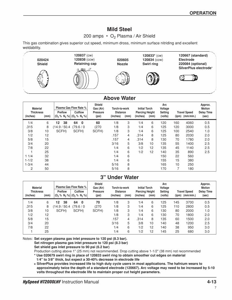
OPERATION
HySpeed HT2000LHF Instruction Manual 4-137
Shield Arc Approx.Material Plasma Gas Flow Rate % Gas (Air) Torch-to-work Initial Torch Voltage Motion
Thickness Preflow Cutflow Pressure Distance Piercing Height Setting Travel Speed Delay Time(inches) (mm) (O2 % N2 %) (O2 % N2 %) (psi) (inches) (mm) (inches) (mm) (volts) (ipm) (mm/min.) (sec)
Shield Arc Approx.Material Plasma Gas Flow Rate % Gas (Air) Torch-to-work Initial Torch Voltage Motion
Thickness Preflow Cutflow Pressure Distance Piercing Height Setting Travel Speed Delay Time(inches) (mm) (O2 % N2 %) (O2 % N2 %) (psi) (inches) (mm) (inches) (mm) (volts) (ipm) (mm/min.) (sec)
1/4 6 12 38 64 0 60 1/8 3 1/4 6 120 160 4060 0.5.315 8 (14.9 / 50.4 (79.6 / 0 (270 1/8 3 1/4 6 125 120 3000 0.53/8 10 SCFH) SCFH) SCFH) 1/8 3 1/4 6 125 100 2540 1.01/2 12 .157 4 .314 8 125 80 2030 2.05/8 15 .157 4 .314 8 130 70 1780 2.03/4 20 3/16 5 3/8 10 135 55 1400 2.57/8 22 1/4 6 1/2 12 135 45 1140 2.5
1 25 1/4 6 1/2 12 140 35 890 2.51 1/4 32 1/4 6 150 22 5601-1/2 38 1/4 6 155 15 3801-3/4 44 5/16 8 165 10 250
2 50 5/16 8 170 7 180
Mild Steel200 amps • O2 Plasma / Air Shield
This gas combination gives superior cut speed, minimum dross, minimum surface nitriding and excellentweldability.
Above Water
1/4 6 12 38 64 0 70 1/8 3 1/4 6 125 145 3700 0.5.315 8 (14.9 / 50.4 (79.6 / 0 (270 1/8 3 1/4 6 125 110 2800 0.53/8 10 SCFH) SCFH) SCFH) 1/8 3 1/4 6 130 80 2000 1.01/2 12 1/8 3 1/4 6 130 70 1800 2.05/8 15 .157 4 .314 8 135 60 1500 2.03/4 20 3/16 5 3/8 10 140 48 1200 2.57/8 22 1/4 6 1/2 12 140 38 950 3.0
1 25 1/4 6 1/2 12 145 25 680 3.0
3" Under Water
120833* (cw)120834 (ccw)Swirl ring
020605Nozzle
120837 (cw)120838 (ccw)Retaining cap
020424Shield
120667 (standard)Electrode 220084 (optional)SilverPlus electrode+
Notes: Set oxygen plasma gas inlet pressure to 120 psi (8.3 bar). Set nitrogen plasma gas inlet pressure to 120 psi (8.3 bar)Set shield gas inlet pressure to 90 psi (6.2 bar)Production cutting above 1" (25 mm) not recommended. Drop cutting above 1-1/2" (38 mm) not recommended* Use 020679 swirl ring in place of 120833 swirl ring to obtain smoother cut edges on material
1/4" to 3/8" thick, but expect a 30-40% decrease in electrode life+ SilverPlus provides increased life to high duty cycle users in most applications. The hafnium wears to
approximately twice the depth of a standard electrode (120667). Arc voltage may need to be increased by 5-10volts throughout the electrode life to maintain proper cut height parameters.

OPERATION
4-14 HySpeed HT2000LHF Instruction Manual7
Shield Arc Approx.Material Plasma Gas Flow Rate % Gas (Air) Torch-to-work Initial Torch Voltage Motion
Thickness Preflow Cutflow Pressure Distance Piercing Height Setting Travel Speed Delay Time(inches) (mm) (Air %) (Air %) (psi) (inches) (mm) (inches) (mm) (volts) (ipm) (mm/min.) (sec)
Shield Arc Approx.Material Plasma Gas Flow Rate % Gas (Air) Torch-to-work Initial Torch Voltage Motion
Thickness Preflow Cutflow Pressure Distance Piercing Height Setting Travel Speed Delay Time(inches) (mm) (Air %) (Air %) (psi) (inches) (mm) (inches) (mm) (volts) (ipm) (mm/min.) (sec)
3/16 5 54 65 60 1/8 3 1/4 6 130 200 50801/4 6 (62.3 (75.0 (270 1/8 3 1/4 6 130 135 3400 0.5
.315 8 SCFH) SCFH) SCFH) 1/8 3 1/4 6 135 115 2900 0.53/8 10 1/8 3 1/4 6 135 100 2540 1.01/2 12 .157 4 .314 8 140 80 2030 2.05/8 15 .157 4 .314 8 145 60 1520 2.03/4 20 3/16 5 3/8 10 150 45 1140 2.57/8 22 1/4 6 1/2 12 155 30 760 2.5
1 25 1/4 6 1/2 12 160 25 635 2.51-1/4 32 1/4 6 165 15 3801-1/2 38 1/4 6 170 10 2501-3/4 44 5/16 8 180 7 180
2 50 5/16 8 185 5 130
Mild Steel200 amps • Air Plasma / Air Shield
This gas combination gives good cut speed, low dross levels and is very economical. Some surface nitriding canoccur.
Notes: Set plasma gas inlet pressure to 90 psi (6.2 bar)Set shield gas inlet pressure to 90 psi (6.2 bar)Production cutting above 1" (25 mm) not recommendedDrop cutting above 1-1/2" (38 mm) not recommended
Above Water
1/4 6 54 65 70 1/8 3 1/4 6 130 130 3300 0.5.315 8 (62.3 (75.0 (280 1/8 3 1/4 6 135 110 2700 0.53/8 10 SCFH) SCFH) SCFH) 1/8 3 1/4 6 135 95 2400 1.01/2 12 1/8 3 1/4 6 140 75 1900 2.05/8 15 .157 4 .314 8 145 50 1200 2.03/4 20 3/16 5 3/8 10 150 35 850 2.57/8 22 1/4 6 1/2 12 155 20 530 3.0
1 25 1/4 6 1/2 12 165 15 400 3.0
3" Under Water
020424Shield
120837Retaining cap
020608Nozzle
020679Swirl ring
120667Electrode
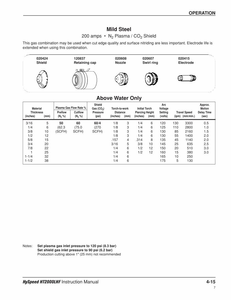
OPERATION
HySpeed HT2000LHF Instruction Manual 4-15
Shield Arc Approx.Material Plasma Gas Flow Rate % Gas (CO2) Torch-to-work Initial Torch Voltage Motion
Thickness Preflow Cutflow Pressure Distance Piercing Height Setting Travel Speed Delay Time(inches) (mm) (N2 %) (N2 %) (psi) (inches) (mm) (inches) (mm) (volts) (ipm) (mm/min.) (sec)
3/16 5 50 60 60/4 1/8 3 1/4 6 120 130 3300 0.51/4 6 (62.3 (75.0 (270 1/8 3 1/4 6 125 110 2800 1.03/8 10 (SCFH) SCFH) SCFH) 1/8 3 1/4 6 130 85 2160 1.51/2 12 1/8 3 1/4 6 130 55 1400 2.05/8 15 .157 4 .314 8 135 45 1140 2.03/4 20 3/16 5 3/8 10 145 25 635 2.57/8 22 1/4 6 1/2 12 150 20 510 3.0
1 25 1/4 6 1/2 12 160 15 380 3.01-1/4 32 1/4 6 165 10 2501-1/2 38 1/4 6 175 5 130
Mild Steel200 amps • N2 Plasma / CO2 Shield
This gas combination may be used when cut edge quality and surface nitriding are less important. Electrode life isextended when using this combination.
Notes: Set plasma gas inlet pressure to 120 psi (8.3 bar)Set shield gas inlet pressure to 90 psi (6.2 bar)Production cutting above 1" (25 mm) not recommended
Above Water Only
020424Shield
120837Retaining cap
020608Nozzle
020607Swirl ring
020415Electrode
7
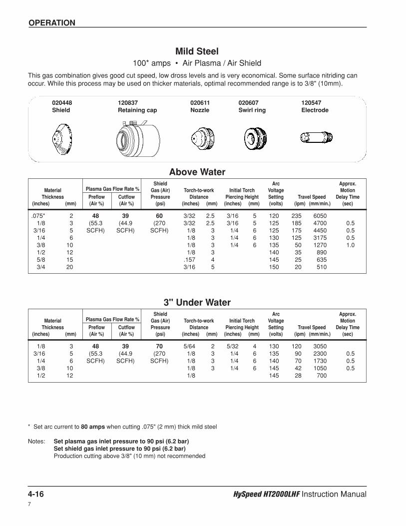
OPERATION
4-16 HySpeed HT2000LHF Instruction Manual7
Shield Arc Approx.Material Plasma Gas Flow Rate % Gas (Air) Torch-to-work Initial Torch Voltage Motion
Thickness Preflow Cutflow Pressure Distance Piercing Height Setting Travel Speed Delay Time(inches) (mm) (Air %) (Air %) (psi) (inches) (mm) (inches) (mm) (volts) (ipm) (mm/min.) (sec)
Shield Arc Approx.Material Plasma Gas Flow Rate % Gas (Air) Torch-to-work Initial Torch Voltage Motion
Thickness Preflow Cutflow Pressure Distance Piercing Height Setting Travel Speed Delay Time(inches) (mm) (Air %) (Air %) (psi) (inches) (mm) (inches) (mm) (volts) (ipm) (mm/min.) (sec)
.075* 2 48 39 60 3/32 2.5 3/16 5 120 235 60501/8 3 (55.3 (44.9 (270 3/32 2.5 3/16 5 125 185 4700 0.5
3/16 5 SCFH) SCFH) SCFH) 1/8 3 1/4 6 125 175 4450 0.51/4 6 1/8 3 1/4 6 130 125 3175 0.53/8 10 1/8 3 1/4 6 135 50 1270 1.01/2 12 1/8 3 140 35 8905/8 15 .157 4 145 25 6353/4 20 3/16 5 150 20 510
Mild Steel100* amps • Air Plasma / Air Shield
This gas combination gives good cut speed, low dross levels and is very economical. Some surface nitriding canoccur. While this process may be used on thicker materials, optimal recommended range is to 3/8" (10mm).
* Set arc current to 80 amps when cutting .075" (2 mm) thick mild steel
Notes: Set plasma gas inlet pressure to 90 psi (6.2 bar)Set shield gas inlet pressure to 90 psi (6.2 bar)Production cutting above 3/8" (10 mm) not recommended
Above Water
1/8 3 48 39 70 5/64 2 5/32 4 130 120 30503/16 5 (55.3 (44.9 (270 1/8 3 1/4 6 135 90 2300 0.51/4 6 SCFH) SCFH) SCFH) 1/8 3 1/4 6 140 70 1730 0.53/8 10 1/8 3 1/4 6 145 42 1050 0.51/2 12 1/8 145 28 700
3" Under Water
020448Shield
120837Retaining cap
020611Nozzle
020607Swirl ring
120547Electrode
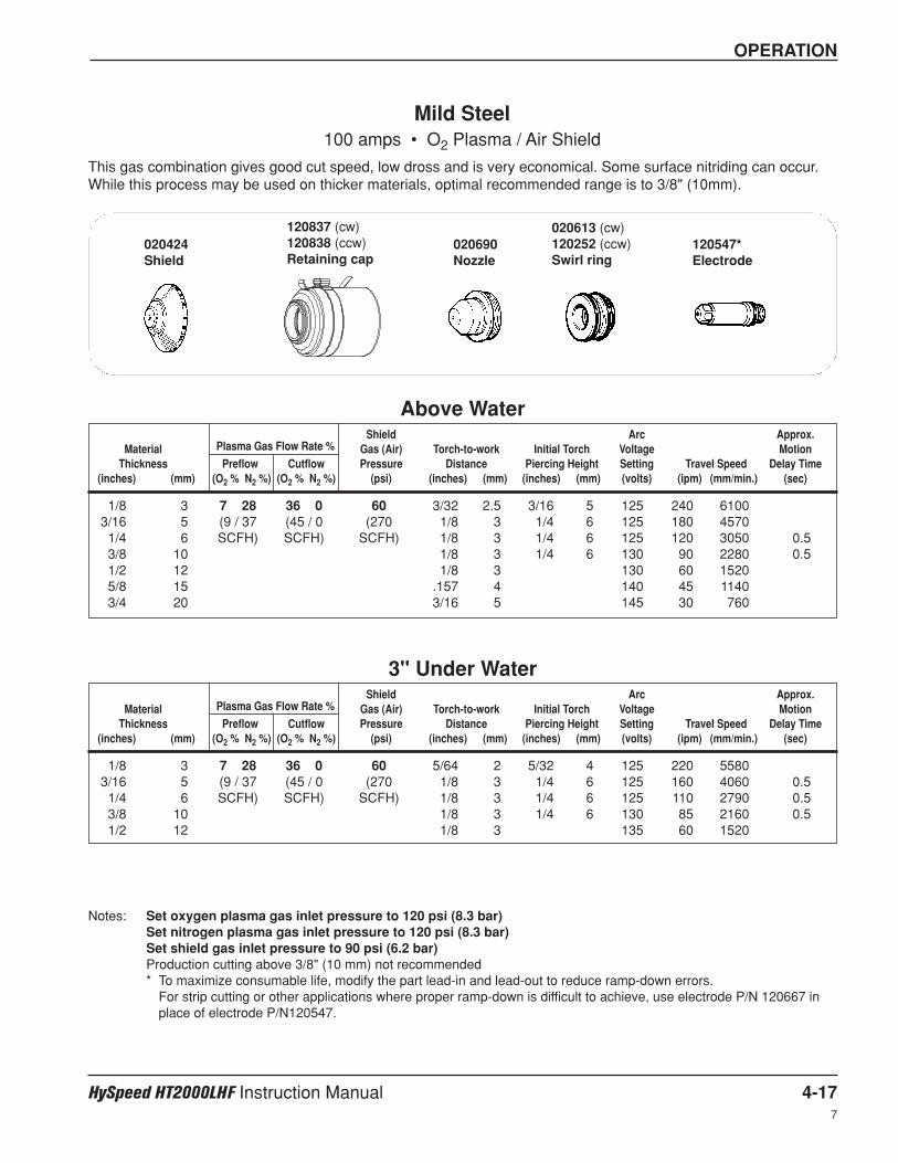
OPERATION
HySpeed HT2000LHF Instruction Manual 4-17
Shield Arc Approx.Material Plasma Gas Flow Rate % Gas (Air) Torch-to-work Initial Torch Voltage Motion
Thickness Preflow Cutflow Pressure Distance Piercing Height Setting Travel Speed Delay Time(inches) (mm) (O2 % N2 %) (O2 % N2 %) (psi) (inches) (mm) (inches) (mm) (volts) (ipm) (mm/min.) (sec)
Shield Arc Approx.Material Plasma Gas Flow Rate % Gas (Air) Torch-to-work Initial Torch Voltage Motion
Thickness Preflow Cutflow Pressure Distance Piercing Height Setting Travel Speed Delay Time(inches) (mm) (O2 % N2 %) (O2 % N2 %) (psi) (inches) (mm) (inches) (mm) (volts) (ipm) (mm/min.) (sec)
1/8 3 7 28 36 0 60 3/32 2.5 3/16 5 125 240 61003/16 5 (9 / 37 (45 / 0 (270 1/8 3 1/4 6 125 180 45701/4 6 SCFH) SCFH) SCFH) 1/8 3 1/4 6 125 120 3050 0.53/8 10 1/8 3 1/4 6 130 90 2280 0.51/2 12 1/8 3 130 60 15205/8 15 .157 4 140 45 11403/4 20 3/16 5 145 30 760
Mild Steel100 amps • O2 Plasma / Air Shield
This gas combination gives good cut speed, low dross and is very economical. Some surface nitriding can occur.While this process may be used on thicker materials, optimal recommended range is to 3/8" (10mm).
Notes: Set oxygen plasma gas inlet pressure to 120 psi (8.3 bar)Set nitrogen plasma gas inlet pressure to 120 psi (8.3 bar)Set shield gas inlet pressure to 90 psi (6.2 bar)Production cutting above 3/8" (10 mm) not recommended* To maximize consumable life, modify the part lead-in and lead-out to reduce ramp-down errors.
For strip cutting or other applications where proper ramp-down is difficult to achieve, use electrode P/N 120667 inplace of electrode P/N120547.
Above Water
1/8 3 7 28 36 0 60 5/64 2 5/32 4 125 220 55803/16 5 (9 / 37 (45 / 0 (270 1/8 3 1/4 6 125 160 4060 0.51/4 6 SCFH) SCFH) SCFH) 1/8 3 1/4 6 125 110 2790 0.53/8 10 1/8 3 1/4 6 130 85 2160 0.51/2 12 1/8 3 135 60 1520
3" Under Water
020613 (cw)120252 (ccw)Swirl ring
120547*Electrode
020690Nozzle
120837 (cw)120838 (ccw)Retaining cap
020424Shield
7
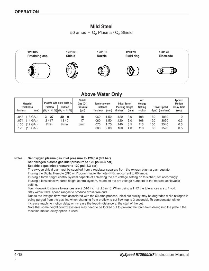
OPERATION
4-18 HySpeed HT2000LHF Instruction Manual7
Shield Arc Approx.Material Plasma Gas Flow Rate % Gas (O2) Torch-to-work Initial Torch Voltage Motion
Thickness Preflow Cutflow Pressure Distance Piercing Height Setting Travel Speed Delay Time(inches) (mm) (O2 % N2 %) (O2 % N2 %) (psi) (inches) (mm) (inches) (mm) (volts) (ipm) (mm/min.) (sec)
.048 (18 GA.) 3 27 30 0 18 .060 1.50 .120 3.0 108 160 4060 0
.074 (14 GA.) 2 / 17 18 / 0 17 .060 1.50 .120 3.0 108 120 3050 0.3
.100 (12 GA.) l/min l/min l/min .070 1.75 .140 3.5 113 100 2540 0.3
.125 (10 GA.) .080 2.00 .160 4.0 118 60 1520 0.5
Mild Steel50 amps • O2 Plasma / O2 Shield
Notes: Set oxygen plasma gas inlet pressure to 120 psi (8.3 bar)Set nitrogen plasma gas inlet pressure to 120 psi (8.3 bar)Set shield gas inlet pressure to 120 psi (8.3 bar)The oxygen shield gas must be supplied from a regulator separate from the oxygen plasma gas regulator.If using the Digital Remote (DR) or Programmable Remote (PR), set current to 60 amps.If using a torch height control system capable of achieving the arc voltage setting on this chart, set accordingly.If using a less sensitive torch height control system, round off the arc voltage numbers to the nearest achievablesetting.Torch-to-work Distance tolerances are ± .010 inch (± .25 mm). When using a THC the tolerances are ± 1 volt.Stay within travel speed ranges to produce dross-free cuts.Due to the low gas flow rates associated with the 50 amp process, initial cut quality may be degraded while nitrogen isbeing purged from the gas line when changing from preflow to cut flow (up to 2 seconds). To compensate, eitherincrease machine motion delay or increase the lead-in distance at the start of the cut.Note that some height control systems may need to be locked out to prevent the torch from diving into the plate if themachine motion delay option is used.
Above Water Only
120185Retaining cap
120186Shield
120182Nozzle
120179Swirl ring
120178Electrode
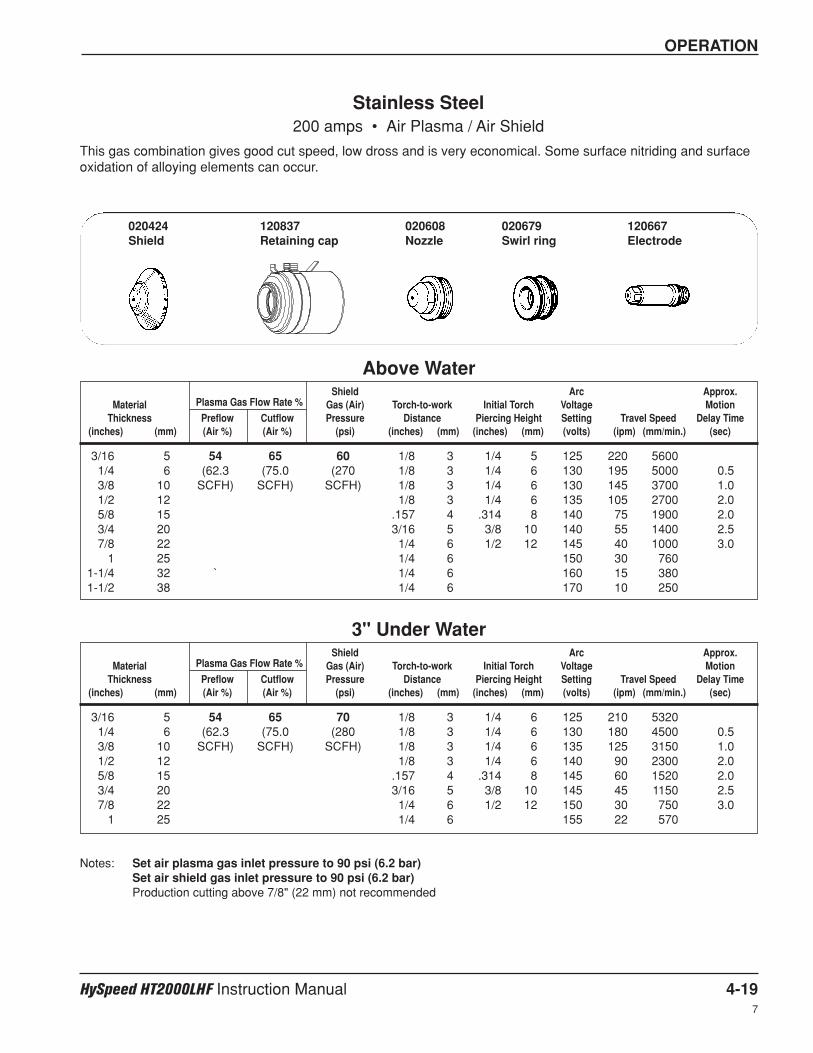
OPERATION
HySpeed HT2000LHF Instruction Manual 4-19
Shield Arc Approx.Material Plasma Gas Flow Rate % Gas (Air) Torch-to-work Initial Torch Voltage Motion
Thickness Preflow Cutflow Pressure Distance Piercing Height Setting Travel Speed Delay Time(inches) (mm) (Air %) (Air %) (psi) (inches) (mm) (inches) (mm) (volts) (ipm) (mm/min.) (sec)
Shield Arc Approx.Material Plasma Gas Flow Rate % Gas (Air) Torch-to-work Initial Torch Voltage Motion
Thickness Preflow Cutflow Pressure Distance Piercing Height Setting Travel Speed Delay Time(inches) (mm) (Air %) (Air %) (psi) (inches) (mm) (inches) (mm) (volts) (ipm) (mm/min.) (sec)
3/16 5 54 65 60 1/8 3 1/4 5 125 220 56001/4 6 (62.3 (75.0 (270 1/8 3 1/4 6 130 195 5000 0.53/8 10 SCFH) SCFH) SCFH) 1/8 3 1/4 6 130 145 3700 1.01/2 12 1/8 3 1/4 6 135 105 2700 2.05/8 15 .157 4 .314 8 140 75 1900 2.03/4 20 3/16 5 3/8 10 140 55 1400 2.57/8 22 1/4 6 1/2 12 145 40 1000 3.0
1 25 1/4 6 150 30 7601-1/4 32 ` 1/4 6 160 15 3801-1/2 38 1/4 6 170 10 250
Stainless Steel200 amps • Air Plasma / Air Shield
This gas combination gives good cut speed, low dross and is very economical. Some surface nitriding and surfaceoxidation of alloying elements can occur.
Notes: Set air plasma gas inlet pressure to 90 psi (6.2 bar)Set air shield gas inlet pressure to 90 psi (6.2 bar)Production cutting above 7/8" (22 mm) not recommended
Above Water
3/16 5 54 65 70 1/8 3 1/4 6 125 210 53201/4 6 (62.3 (75.0 (280 1/8 3 1/4 6 130 180 4500 0.53/8 10 SCFH) SCFH) SCFH) 1/8 3 1/4 6 135 125 3150 1.01/2 12 1/8 3 1/4 6 140 90 2300 2.05/8 15 .157 4 .314 8 145 60 1520 2.03/4 20 3/16 5 3/8 10 145 45 1150 2.57/8 22 1/4 6 1/2 12 150 30 750 3.0
1 25 1/4 6 155 22 570
3" Under Water
020424Shield
120837Retaining cap
020608Nozzle
020679Swirl ring
120667Electrode
7
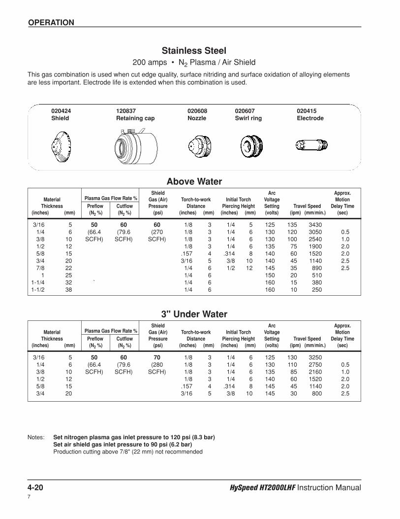
OPERATION
4-20 HySpeed HT2000LHF Instruction Manual7
Shield Arc Approx.Material Plasma Gas Flow Rate % Gas (Air) Torch-to-work Initial Torch Voltage Motion
Thickness Preflow Cutflow Pressure Distance Piercing Height Setting Travel Speed Delay Time(inches) (mm) (N2 %) (N2 %) (psi) (inches) (mm) (inches) (mm) (volts) (ipm) (mm/min.) (sec)
Shield Arc Approx.Material Plasma Gas Flow Rate % Gas (Air) Torch-to-work Initial Torch Voltage Motion
Thickness Preflow Cutflow Pressure Distance Piercing Height Setting Travel Speed Delay Time(inches) (mm) (N2 %) (N2 %) (psi) (inches) (mm) (inches) (mm) (volts) (ipm) (mm/min.) (sec)
3/16 5 50 60 60 1/8 3 1/4 5 125 135 34301/4 6 (66.4 (79.6 (270 1/8 3 1/4 6 130 120 3050 0.53/8 10 SCFH) SCFH) SCFH) 1/8 3 1/4 6 130 100 2540 1.01/2 12 1/8 3 1/4 6 135 75 1900 2.05/8 15 .157 4 .314 8 140 60 1520 2.03/4 20 3/16 5 3/8 10 140 45 1140 2.57/8 22 1/4 6 1/2 12 145 35 890 2.5
1 25 1/4 6 150 20 5101-1/4 32 ` 1/4 6 160 15 3801-1/2 38 1/4 6 160 10 250
Stainless Steel200 amps • N2 Plasma / Air Shield
This gas combination is used when cut edge quality, surface nitriding and surface oxidation of alloying elementsare less important. Electrode life is extended when this combination is used.
Notes: Set nitrogen plasma gas inlet pressure to 120 psi (8.3 bar)Set air shield gas inlet pressure to 90 psi (6.2 bar)Production cutting above 7/8" (22 mm) not recommended
Above Water
3/16 5 50 60 70 1/8 3 1/4 6 125 130 32501/4 6 (66.4 (79.6 (280 1/8 3 1/4 6 130 110 2750 0.53/8 10 SCFH) SCFH) SCFH) 1/8 3 1/4 6 135 85 2160 1.01/2 12 1/8 3 1/4 6 140 60 1520 2.05/8 15 .157 4 .314 8 145 45 1140 2.03/4 20 3/16 5 3/8 10 145 30 800 2.5
3" Under Water
020424Shield
120837Retaining cap
020608Nozzle
020607Swirl ring
020415Electrode
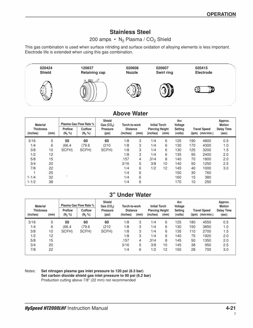
OPERATION
HySpeed HT2000LHF Instruction Manual 4-21
Shield Arc Approx.Material Plasma Gas Flow Rate % Gas (CO2) Torch-to-work Initial Torch Voltage Motion
Thickness Preflow Cutflow Pressure Distance Piercing Height Setting Travel Speed Delay Time(inches) (mm) (N2 %) (N2 %) (psi) (inches) (mm) (inches) (mm) (volts) (ipm) (mm/min.) (sec)
Shield Arc Approx.Material Plasma Gas Flow Rate % Gas (CO2) Torch-to-work Initial Torch Voltage Motion
Thickness Preflow Cutflow Pressure Distance Piercing Height Setting Travel Speed Delay Time(inches) (mm) (N2 %) (N2 %) (psi) (inches) (mm) (inches) (mm) (volts) (ipm) (mm/min.) (sec)
3/16 5 50 60 60 1/8 3 1/4 6 125 190 4800 0.51/4 6 (66.4 (79.6 (210 1/8 3 1/4 6 130 170 4300 1.03/8 10 SCFH) SCFH) SCFH) 1/8 3 1/4 6 130 125 3200 1.51/2 12 1/8 3 1/4 6 135 95 2400 2.05/8 15 .157 4 .314 8 140 70 1800 2.03/4 20 3/16 5 3/8 10 140 50 1250 2.57/8 22 1/4 6 1/2 12 145 40 1000 3.0
1 25 1/4 6 150 30 7601-1/4 32 ` 1/4 6 160 15 3801-1/2 38 1/4 6 170 10 250
Stainless Steel200 amps • N2 Plasma / CO2 Shield
This gas combination is used when surface nitriding and surface oxidation of alloying elements is less important.Electrode life is extended when using this gas combination.
Notes: Set nitrogen plasma gas inlet pressure to 120 psi (8.3 bar)Set carbon dioxide shield gas inlet pressure to 90 psi (6.2 bar)Production cutting above 7/8" (22 mm) not recommended
Above Water
3/16 5 50 60 60 1/8 3 1/4 6 125 180 4550 0.51/4 6 (66.4 (79.6 (210 1/8 3 1/4 6 130 150 3850 1.03/8 10 SCFH) SCFH) SCFH) 1/8 3 1/4 6 135 110 2700 1.51/2 12 1/8 3 1/4 6 140 75 1920 2.05/8 15 .157 4 .314 8 145 50 1350 2.03/4 20 3/16 5 3/8 10 145 38 950 2.57/8 22 1/4 6 1/2 12 150 28 700 3.0
3" Under Water
020424Shield
120837Retaining cap
020608Nozzle
020607Swirl ring
020415Electrode
7
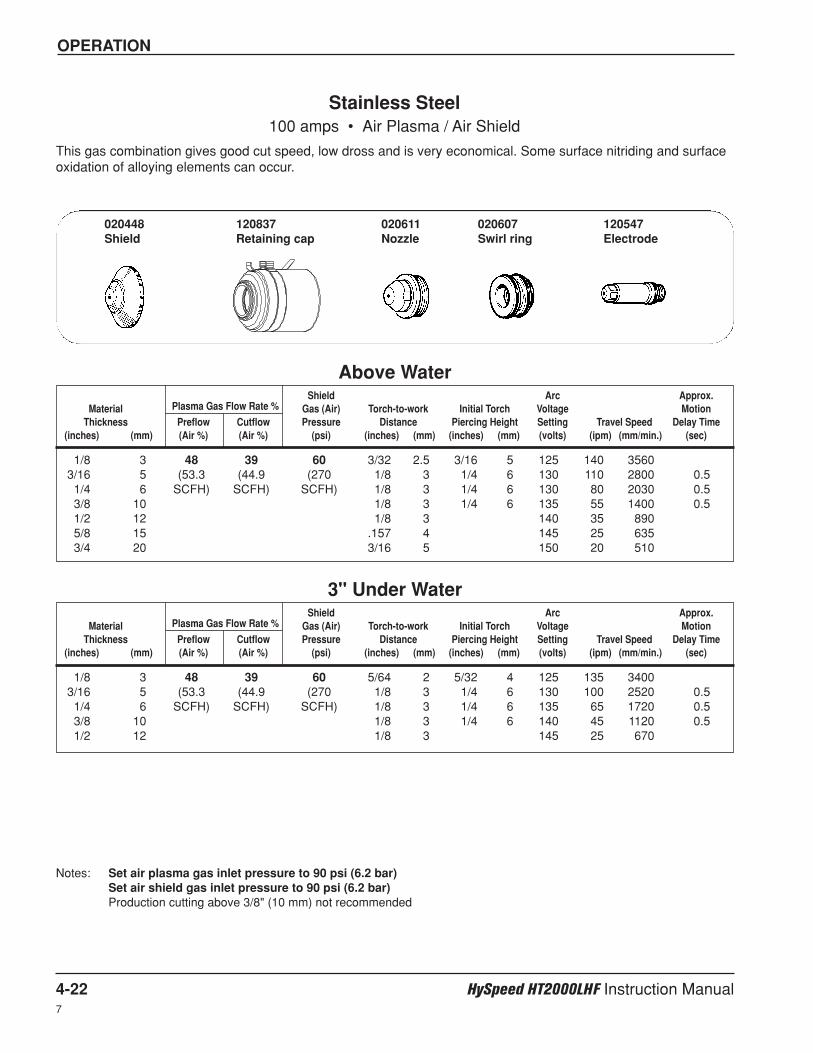
OPERATION
4-22 HySpeed HT2000LHF Instruction Manual7
Shield Arc Approx.Material Plasma Gas Flow Rate % Gas (Air) Torch-to-work Initial Torch Voltage Motion
Thickness Preflow Cutflow Pressure Distance Piercing Height Setting Travel Speed Delay Time(inches) (mm) (Air %) (Air %) (psi) (inches) (mm) (inches) (mm) (volts) (ipm) (mm/min.) (sec)
Shield Arc Approx.Material Plasma Gas Flow Rate % Gas (Air) Torch-to-work Initial Torch Voltage Motion
Thickness Preflow Cutflow Pressure Distance Piercing Height Setting Travel Speed Delay Time(inches) (mm) (Air %) (Air %) (psi) (inches) (mm) (inches) (mm) (volts) (ipm) (mm/min.) (sec)
1/8 3 48 39 60 3/32 2.5 3/16 5 125 140 35603/16 5 (53.3 (44.9 (270 1/8 3 1/4 6 130 110 2800 0.51/4 6 SCFH) SCFH) SCFH) 1/8 3 1/4 6 130 80 2030 0.53/8 10 1/8 3 1/4 6 135 55 1400 0.51/2 12 1/8 3 140 35 8905/8 15 .157 4 145 25 6353/4 20 3/16 5 150 20 510
Stainless Steel100 amps • Air Plasma / Air Shield
This gas combination gives good cut speed, low dross and is very economical. Some surface nitriding and surfaceoxidation of alloying elements can occur.
Notes: Set air plasma gas inlet pressure to 90 psi (6.2 bar)Set air shield gas inlet pressure to 90 psi (6.2 bar)Production cutting above 3/8" (10 mm) not recommended
Above Water
1/8 3 48 39 60 5/64 2 5/32 4 125 135 34003/16 5 (53.3 (44.9 (270 1/8 3 1/4 6 130 100 2520 0.51/4 6 SCFH) SCFH) SCFH) 1/8 3 1/4 6 135 65 1720 0.53/8 10 1/8 3 1/4 6 140 45 1120 0.51/2 12 1/8 3 145 25 670
3" Under Water
020448Shield
120837Retaining cap
020611Nozzle
020607Swirl ring
120547Electrode

OPERATION
HySpeed HT2000LHF Instruction Manual 4-23
Shield Arc Approx.Material Plasma Gas Flow Rate % Gas (Air) Torch-to-work Initial Torch Voltage Motion
Thickness Preflow Cutflow Pressure Distance Piercing Height Setting Travel Speed Delay Time(inches) (mm) (Air %) (Air %) (psi) (inches) (mm) (inches) (mm) (volts) (ipm) (mm/min.) (sec)
.050 (18 GA.) 40 20 60 3/32 2.5 3/16 5 120 145 37001/16 1.5 (46.0 (23.1 (275 3/32 2.5 3/16 5 120 120 30501/8 3 SCFH) SCFH) SCFH) 3/32 2.5 3/16 5 125 75 1900 0.51/4 6 1/8 3 135 24 6103/8 10 1/8 3 140 12 300
Stainless Steel40 amps • Air Plasma / Air Shield
This gas combination gives good cut speed, low dross level and is very economical. Some surface nitriding andsurface oxidation of alloying elements can occur.
Notes: Set air plasma gas inlet pressure to 90 psi (6.2 bar)Set air shield gas inlet pressure to 90 psi (6.2 bar)Production cutting above 1/8" (3 mm) not recommended
Above Water Only
020688Shield
120837Retaining cap
020689Nozzle
020613Swirl ring
120667Electrode
7
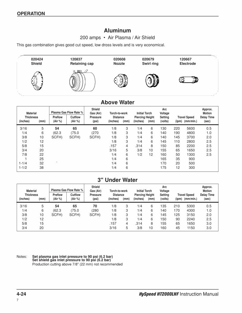
OPERATION
4-24 HySpeed HT2000LHF Instruction Manual7
Shield Arc Approx.Material Plasma Gas Flow Rate % Gas (Air) Torch-to-work Initial Torch Voltage Motion
Thickness Preflow Cutflow Pressure Distance Piercing Height Setting Travel Speed Delay Time(inches) (mm) (Air %) (Air %) (psi) (inches) (mm) (inches) (mm) (volts) (ipm) (mm/min.) (sec)
Shield Arc Approx.Material Plasma Gas Flow Rate % Gas (Air) Torch-to-work Initial Torch Voltage Motion
Thickness Preflow Cutflow Pressure Distance Piercing Height Setting Travel Speed Delay Time(inches) (mm) (Air %) (Air %) (psi) (inches) (mm) (inches) (mm) (volts) (ipm) (mm/min.) (sec)
3/16 5 54 65 60 1/8 3 1/4 6 130 220 5600 0.51/4 6 (62.3 (75.0 (270 1/8 3 1/4 6 140 190 4800 1.03/8 10 SCFH) SCFH) SCFH) 1/8 3 1/4 6 140 145 3700 2.01/2 12 1/8 3 1/4 6 145 110 2800 2.55/8 15 .157 4 .314 8 150 85 2200 2.53/4 20 3/16 5 3/8 10 155 65 1650 2.57/8 22 1/4 6 1/2 12 160 50 1300 2.5
1 25 1/4 6 165 35 9001-1/4 32 ` 1/4 6 170 20 5001-1/2 38 1/4 6 175 12 300
Aluminum200 amps • Air Plasma / Air Shield
This gas combination gives good cut speed, low dross levels and is very economical.
Notes: Set plasma gas inlet pressure to 90 psi (6.2 bar)Set shield gas inlet pressure to 90 psi (6.2 bar)Production cutting above 7/8" (22 mm) not recommended
Above Water
3/16 5 54 65 70 1/8 3 1/4 6 135 210 5300 0.51/4 6 (62.3 (75.0 (280 1/8 3 1/4 6 140 170 4300 1.03/8 10 SCFH) SCFH) SCFH) 1/8 3 1/4 6 145 125 3150 2.01/2 12 1/8 3 1/4 6 150 90 2240 2.55/8 15 .157 4 .314 8 155 65 1650 3.03/4 20 3/16 5 3/8 10 160 45 1150 3.0
3" Under Water
020424Shield
120837Retaining cap
020608Nozzle
020679Swirl ring
120667Electrode
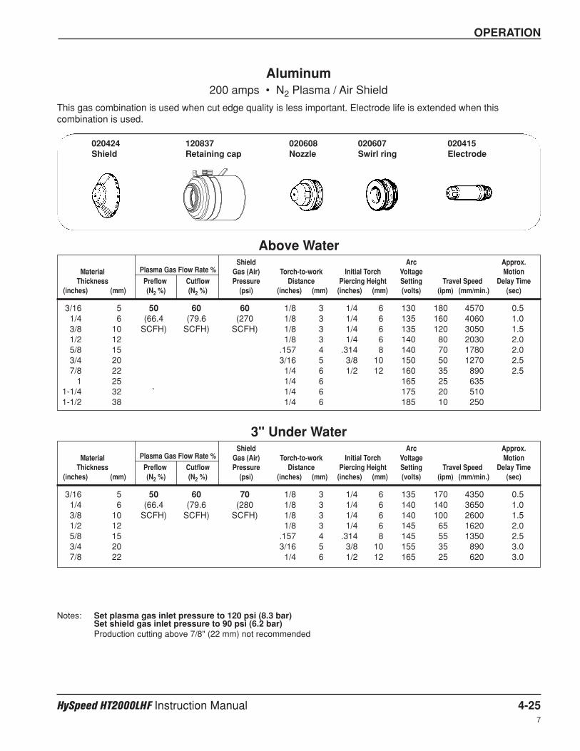
OPERATION
HySpeed HT2000LHF Instruction Manual 4-25
Shield Arc Approx.Material Plasma Gas Flow Rate % Gas (Air) Torch-to-work Initial Torch Voltage Motion
Thickness Preflow Cutflow Pressure Distance Piercing Height Setting Travel Speed Delay Time(inches) (mm) (N2 %) (N2 %) (psi) (inches) (mm) (inches) (mm) (volts) (ipm) (mm/min.) (sec)
Shield Arc Approx.Material Plasma Gas Flow Rate % Gas (Air) Torch-to-work Initial Torch Voltage Motion
Thickness Preflow Cutflow Pressure Distance Piercing Height Setting Travel Speed Delay Time(inches) (mm) (N2 %) (N2 %) (psi) (inches) (mm) (inches) (mm) (volts) (ipm) (mm/min.) (sec)
3/16 5 50 60 60 1/8 3 1/4 6 130 180 4570 0.51/4 6 (66.4 (79.6 (270 1/8 3 1/4 6 135 160 4060 1.03/8 10 SCFH) SCFH) SCFH) 1/8 3 1/4 6 135 120 3050 1.51/2 12 1/8 3 1/4 6 140 80 2030 2.05/8 15 .157 4 .314 8 140 70 1780 2.03/4 20 3/16 5 3/8 10 150 50 1270 2.57/8 22 1/4 6 1/2 12 160 35 890 2.5
1 25 1/4 6 165 25 6351-1/4 32 ` 1/4 6 175 20 5101-1/2 38 1/4 6 185 10 250
Aluminum200 amps • N2 Plasma / Air Shield
This gas combination is used when cut edge quality is less important. Electrode life is extended when thiscombination is used.
Notes: Set plasma gas inlet pressure to 120 psi (8.3 bar)Set shield gas inlet pressure to 90 psi (6.2 bar)Production cutting above 7/8" (22 mm) not recommended
Above Water
3/16 5 50 60 70 1/8 3 1/4 6 135 170 4350 0.51/4 6 (66.4 (79.6 (280 1/8 3 1/4 6 140 140 3650 1.03/8 10 SCFH) SCFH) SCFH) 1/8 3 1/4 6 140 100 2600 1.51/2 12 1/8 3 1/4 6 145 65 1620 2.05/8 15 .157 4 .314 8 145 55 1350 2.53/4 20 3/16 5 3/8 10 155 35 890 3.07/8 22 1/4 6 1/2 12 165 25 620 3.0
3" Under Water
020424Shield
120837Retaining cap
020608Nozzle
020607Swirl ring
020415Electrode
7
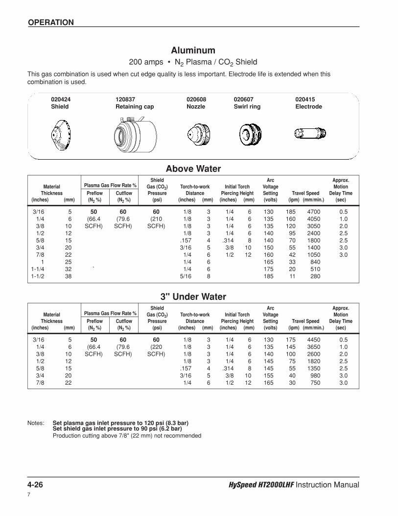
OPERATION
4-26 HySpeed HT2000LHF Instruction Manual7
Shield Arc Approx.Material Plasma Gas Flow Rate % Gas (CO2) Torch-to-work Initial Torch Voltage Motion
Thickness Preflow Cutflow Pressure Distance Piercing Height Setting Travel Speed Delay Time(inches) (mm) (N2 %) (N2 %) (psi) (inches) (mm) (inches) (mm) (volts) (ipm) (mm/min.) (sec)
Shield Arc Approx.Material Plasma Gas Flow Rate % Gas (CO2) Torch-to-work Initial Torch Voltage Motion
Thickness Preflow Cutflow Pressure Distance Piercing Height Setting Travel Speed Delay Time(inches) (mm) (N2 %) (N2 %) (psi) (inches) (mm) (inches) (mm) (volts) (ipm) (mm/min.) (sec)
3/16 5 50 60 60 1/8 3 1/4 6 130 185 4700 0.51/4 6 (66.4 (79.6 (210 1/8 3 1/4 6 135 160 4050 1.03/8 10 SCFH) SCFH) SCFH) 1/8 3 1/4 6 135 120 3050 2.01/2 12 1/8 3 1/4 6 140 95 2400 2.55/8 15 .157 4 .314 8 140 70 1800 2.53/4 20 3/16 5 3/8 10 150 55 1400 3.07/8 22 1/4 6 1/2 12 160 42 1050 3.0
1 25 1/4 6 165 33 8401-1/4 32 ` 1/4 6 175 20 5101-1/2 38 5/16 8 185 11 280
Aluminum200 amps • N2 Plasma / CO2 Shield
This gas combination is used when cut edge quality is less important. Electrode life is extended when thiscombination is used.
Notes: Set plasma gas inlet pressure to 120 psi (8.3 bar)Set shield gas inlet pressure to 90 psi (6.2 bar)Production cutting above 7/8" (22 mm) not recommended
Above Water
3/16 5 50 60 60 1/8 3 1/4 6 130 175 4450 0.51/4 6 (66.4 (79.6 (220 1/8 3 1/4 6 135 145 3650 1.03/8 10 SCFH) SCFH) SCFH) 1/8 3 1/4 6 140 100 2600 2.01/2 12 1/8 3 1/4 6 145 75 1820 2.55/8 15 .157 4 .314 8 145 55 1350 2.53/4 20 3/16 5 3/8 10 155 40 980 3.07/8 22 1/4 6 1/2 12 165 30 750 3.0
3" Under Water
020424Shield
120837Retaining cap
020608Nozzle
020607Swirl ring
020415Electrode
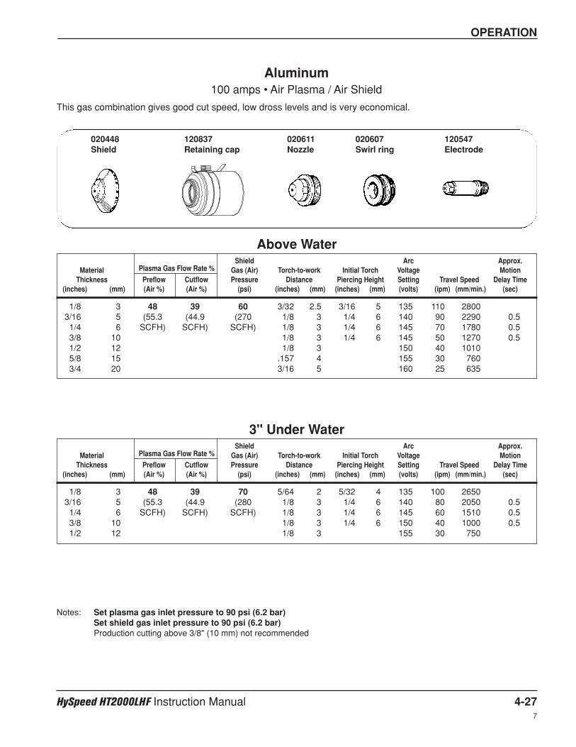
OPERATION
HySpeed HT2000LHF Instruction Manual 4-27
Shield Arc Approx.Material Plasma Gas Flow Rate % Gas (Air) Torch-to-work Initial Torch Voltage Motion
Thickness Preflow Cutflow Pressure Distance Piercing Height Setting Travel Speed Delay Time(inches) (mm) (Air %) (Air %) (psi) (inches) (mm) (inches) (mm) (volts) (ipm) (mm/min.) (sec)
Shield Arc Approx.Material Plasma Gas Flow Rate % Gas (Air) Torch-to-work Initial Torch Voltage Motion
Thickness Preflow Cutflow Pressure Distance Piercing Height Setting Travel Speed Delay Time(inches) (mm) (Air %) (Air %) (psi) (inches) (mm) (inches) (mm) (volts) (ipm) (mm/min.) (sec)
1/8 3 48 39 60 3/32 2.5 3/16 5 135 110 28003/16 5 (55.3 (44.9 (270 1/8 3 1/4 6 140 90 2290 0.51/4 6 SCFH) SCFH) SCFH) 1/8 3 1/4 6 145 70 1780 0.53/8 10 1/8 3 1/4 6 145 50 1270 0.51/2 12 1/8 3 150 40 10105/8 15 .157 4 155 30 7603/4 20 3/16 5 160 25 635
Aluminum100 amps • Air Plasma / Air Shield
This gas combination gives good cut speed, low dross levels and is very economical.
Notes: Set plasma gas inlet pressure to 90 psi (6.2 bar)Set shield gas inlet pressure to 90 psi (6.2 bar)Production cutting above 3/8" (10 mm) not recommended
Above Water
1/8 3 48 39 70 5/64 2 5/32 4 135 100 26503/16 5 (55.3 (44.9 (280 1/8 3 1/4 6 140 80 2050 0.51/4 6 SCFH) SCFH) SCFH) 1/8 3 1/4 6 145 60 1510 0.53/8 10 1/8 3 1/4 6 150 40 1000 0.51/2 12 1/8 3 155 30 750
3" Under Water
020448Shield
120837Retaining cap
020611Nozzle
020607Swirl ring
120547Electrode
7
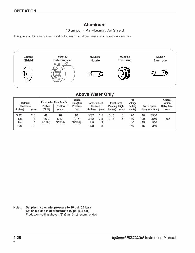
OPERATION
4-28 HySpeed HT2000LHF Instruction Manual7
Shield Arc Approx.Material Plasma Gas Flow Rate % Gas (Air) Torch-to-work Initial Torch Voltage Motion
Thickness Preflow Cutflow Pressure Distance Piercing Height Setting Travel Speed Delay Time(inches) (mm) (Air %) (Air %) (psi) (inches) (mm) (inches) (mm) (volts) (ipm) (mm/min.) (sec)
3/32 2.5 40 20 60 3/32 2.5 3/16 5 120 140 35501/8 3 (46.0 (23.1 (275 3/32 2.5 3/16 5 130 100 2550 0.51/4 6 SCFH) SCFH) SCFH) 1/8 3 140 35 9003/8 10 1/8 3 150 15 350
Aluminum40 amps • Air Plasma / Air Shield
This gas combination gives good cut speed, low dross levels and is very economical.
Notes: Set plasma gas inlet pressure to 90 psi (6.2 bar)Set shield gas inlet pressure to 90 psi (6.2 bar)Production cutting above 1/8" (3 mm) not recommended
Above Water Only
020613Swirl ring
120667Electrode
020689Nozzle
020423Retaining cap
020688Shield
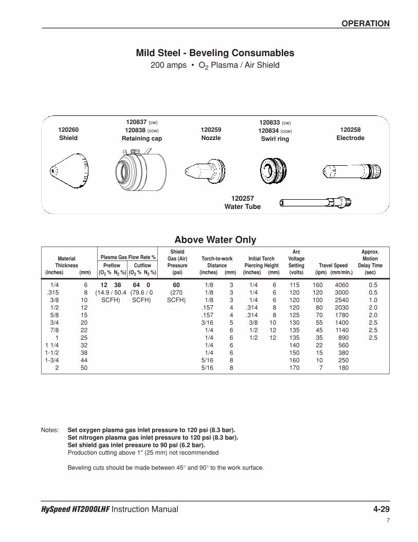
OPERATION
HySpeed HT2000LHF Instruction Manual 4-29
Shield Arc Approx.Material Plasma Gas Flow Rate % Gas (Air) Torch-to-work Initial Torch Voltage Motion
Thickness Preflow Cutflow Pressure Distance Piercing Height Setting Travel Speed Delay Time(inches) (mm) (O2 % N2 %) (O2 % N2 %) (psi) (inches) (mm) (inches) (mm) (volts) (ipm) (mm/min.) (sec)
1/4 6 12 38 64 0 60 1/8 3 1/4 6 115 160 4060 0.5.315 8 (14.9 / 50.4 (79.6 / 0 (270 1/8 3 1/4 6 120 120 3000 0.53/8 10 SCFH) SCFH) SCFH) 1/8 3 1/4 6 120 100 2540 1.01/2 12 .157 4 .314 8 120 80 2030 2.05/8 15 .157 4 .314 8 125 70 1780 2.03/4 20 3/16 5 3/8 10 130 55 1400 2.57/8 22 1/4 6 1/2 12 135 45 1140 2.5
1 25 1/4 6 1/2 12 135 35 890 2.51 1/4 32 1/4 6 140 22 5601-1/2 38 1/4 6 150 15 3801-3/4 44 5/16 8 160 10 250
2 50 5/16 8 170 7 180
Mild Steel - Beveling Consumables200 amps • O2 Plasma / Air Shield
Notes: Set oxygen plasma gas inlet pressure to 120 psi (8.3 bar).Set nitrogen plasma gas inlet pressure to 120 psi (8.3 bar).Set shield gas inlet pressure to 90 psi (6.2 bar).Production cutting above 1" (25 mm) not recommended
Beveling cuts should be made between 45° and 90° to the work surface.
Above Water Only
120833 (cw)
120834 (ccw)
Swirl ring
120258Electrode
120257Water Tube
120259Nozzle
120837 (cw)
120838 (ccw)
Retaining cap120260Shield
7
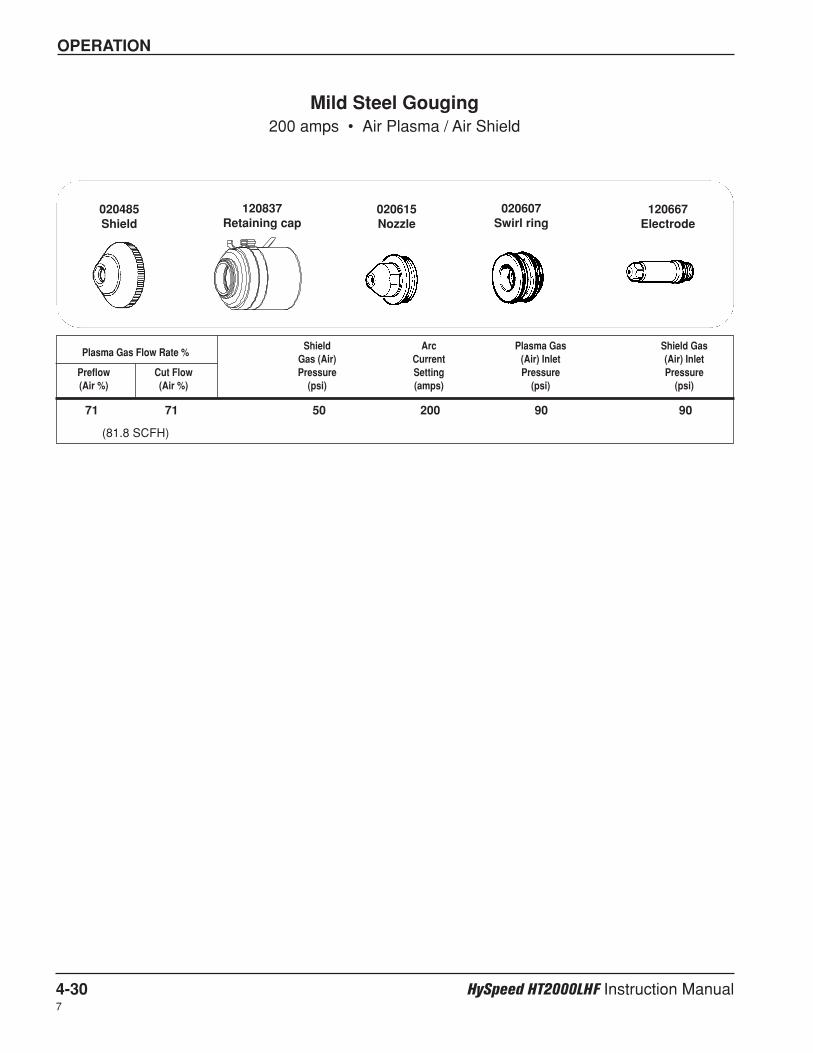
OPERATION
4-30 HySpeed HT2000LHF Instruction Manual7
Shield Arc Plasma Gas Shield GasPlasma Gas Flow Rate %
Gas (Air) Current (Air) Inlet (Air) InletPreflow Cut Flow Pressure Setting Pressure Pressure(Air %) (Air %) (psi) (amps) (psi) (psi)
71 71 50 200 90 90
(81.8 SCFH)
Mild Steel Gouging200 amps • Air Plasma / Air Shield
020607Swirl ring
120667Electrode
020615Nozzle
120837Retaining cap
020485Shield
OPERATION
HySpeed HT2000LHF Instruction Manual 4-31
Check the consumable parts daily for wear before cutting. Before removing parts, bring the torch to the edgeof the machine, with the lifter raised to its highest point. This prevents the danger of dropping theconsumables into the water of the water table.
Removal and Inspection – Refer to Figure 4-7
1. Remove the retaining cap and shield by unscrewing the retaining cap by hand.
2. Check the shield for external signs of wear. It should be clean and clear of metal debris. The gas holesalong the edge of the shield should not be blocked with debris. The center hole should not have any nicksor gouges, and should show no signs of arcing activity.
3. Unscrew and remove the shield from the retaining cap. Inspect the gas holes from the inside. The holesshould be clear of metal or other debris. (Debris can cause arcing.)
4. Inspect the two O-rings on the torch body. They should be lubricated and undamaged. If they are dry,lubricate them lightly with a very thin film of the lubricant provided in the consumable parts kit. If they aredamaged, replace them.
5. Using the 3/4" side of the wrench supplied with the consumable parts kit, remove the nozzle. Inspect it fordamage or signs of wear. You can clean the inside of the nozzle with steel wool, but be sure to remove anyremnants of the steel wool afterward. The hole in the nozzle should not be worn or oval-shaped.
6. Using the 3/8" center hole in the wrench, remove the Electrode and inspect it. If the center of an all copperelectrode has a pit more than .044" (1.1 mm) deep, replace it. A SilverPlus electrode should be replacedwhen the pit depth exceeds approximately double the recommended depth of a standard copper electrode.Use the electrode gauge assembly supplied in the spare parts kit to measure pit depth. If the electrode isstill good, inspect its O-ring: it should be lubricated and undamaged. If it is dry, lubricate it lightly with avery thin film of lubricant provided in the spare parts kit. If it is damaged, replace it.
7. Remove the swirl ring from the electrode and inspect it. It should be clean, and the holes on the top andsides should not be plugged. Inspect its O-ring. It should be lubricated and undamaged. If it is dry,lubricate it lightly with a very thin film of the lubricant provided in the consumable parts kit. If it is damaged,replace it.
8. Inspect the inside of the torch body by using a mirror, or by looking carefully inside. The current ring insideof the torch body should be clean and undamaged. Use a clean paper towel or cotton swab to remove dirt,grease, etc. A preferred method to clean the current ring is with a clean paper towel or cotton swab dippedin water or 3% hydrogen peroxide. If the water tube is damaged at all, it may need to be replaced. SeeChanging the Water Tube.
CHANGING CONSUMABLE PARTS
WARNING
Always disconnect power to the power supply before inspecting or changing torch consumableparts.
7
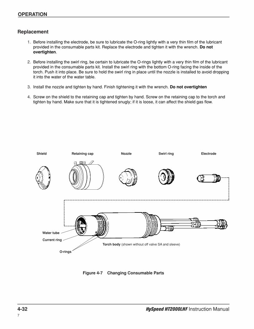
OPERATION
4-32 HySpeed HT2000LHF Instruction Manual7
Replacement
1. Before installing the electrode, be sure to lubricate the O-ring lightly with a very thin film of the lubricantprovided in the consumable parts kit. Replace the electrode and tighten it with the wrench. Do notovertighten.
2. Before installing the swirl ring, be certain to lubricate the O-rings lightly with a very thin film of the lubricantprovided in the consumable parts kit. Install the swirl ring with the bottom O-ring facing the inside of thetorch. Push it into place. Be sure to hold the swirl ring in place until the nozzle is installed to avoid droppingit into the water of the water table.
3. Install the nozzle and tighten by hand. Finish tightening it with the wrench. Do not overtighten
4. Screw on the shield to the retaining cap and tighten by hand. Screw on the retaining cap to the torch andtighten by hand. Make sure that it is tightened snugly; if it is loose, it can affect the shield gas flow.
Figure 4-7 Changing Consumable Parts
Shield Retaining cap Nozzle Swirl ring Electrode
Current ring
O-rings
Water tube
Torch body (shown without off valve SA and sleeve)
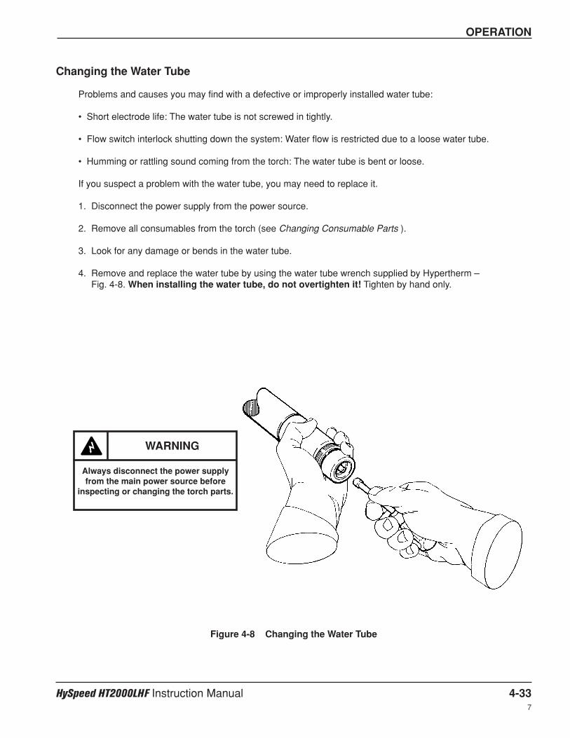
OPERATION
HySpeed HT2000LHF Instruction Manual 4-337
Changing the Water Tube
Problems and causes you may find with a defective or improperly installed water tube:
• Short electrode life: The water tube is not screwed in tightly.
• Flow switch interlock shutting down the system: Water flow is restricted due to a loose water tube.
• Humming or rattling sound coming from the torch: The water tube is bent or loose.
If you suspect a problem with the water tube, you may need to replace it.
1. Disconnect the power supply from the power source.
2. Remove all consumables from the torch (see Changing Consumable Parts ).
3. Look for any damage or bends in the water tube.
4. Remove and replace the water tube by using the water tube wrench supplied by Hypertherm – Fig. 4-8. When installing the water tube, do not overtighten it! Tighten by hand only.
Figure 4-8 Changing the Water Tube
WARNING
Always disconnect the power supplyfrom the main power source before
inspecting or changing the torch parts.
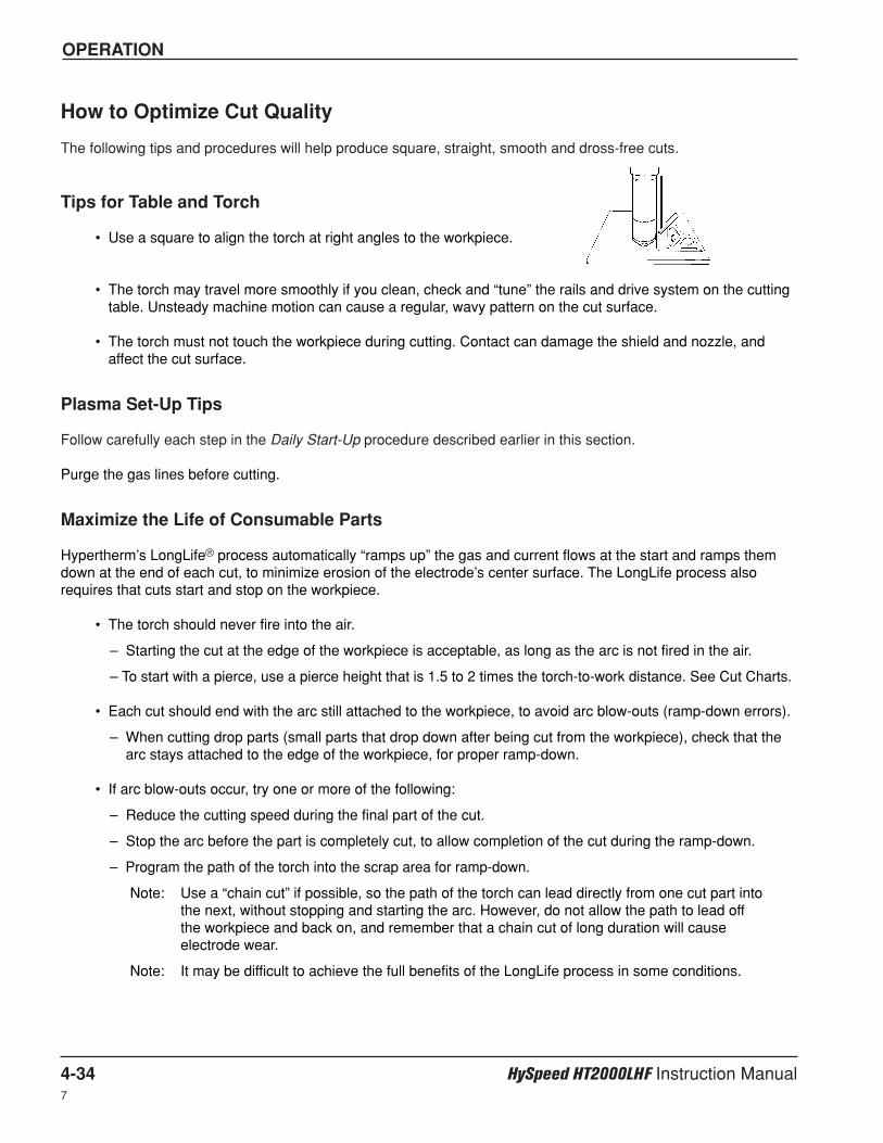
OPERATION
4-34 HySpeed HT2000LHF Instruction Manual7
How to Optimize Cut Quality
The following tips and procedures will help produce square, straight, smooth and dross-free cuts.
Tips for Table and Torch
• Use a square to align the torch at right angles to the workpiece.
• The torch may travel more smoothly if you clean, check and “tune” the rails and drive system on the cuttingtable. Unsteady machine motion can cause a regular, wavy pattern on the cut surface.
• The torch must not touch the workpiece during cutting. Contact can damage the shield and nozzle, andaffect the cut surface.
Plasma Set-Up Tips
Follow carefully each step in the Daily Start-Up procedure described earlier in this section.
Purge the gas lines before cutting.
Maximize the Life of Consumable Parts
Hypertherm’s LongLife® process automatically “ramps up” the gas and current flows at the start and ramps themdown at the end of each cut, to minimize erosion of the electrode’s center surface. The LongLife process alsorequires that cuts start and stop on the workpiece.
• The torch should never fire into the air.
– Starting the cut at the edge of the workpiece is acceptable, as long as the arc is not fired in the air.
– To start with a pierce, use a pierce height that is 1.5 to 2 times the torch-to-work distance. See Cut Charts.
• Each cut should end with the arc still attached to the workpiece, to avoid arc blow-outs (ramp-down errors).
– When cutting drop parts (small parts that drop down after being cut from the workpiece), check that thearc stays attached to the edge of the workpiece, for proper ramp-down.
• If arc blow-outs occur, try one or more of the following:
– Reduce the cutting speed during the final part of the cut.
– Stop the arc before the part is completely cut, to allow completion of the cut during the ramp-down.
– Program the path of the torch into the scrap area for ramp-down.
Note: Use a “chain cut” if possible, so the path of the torch can lead directly from one cut part intothe next, without stopping and starting the arc. However, do not allow the path to lead offthe workpiece and back on, and remember that a chain cut of long duration will causeelectrode wear.
Note: It may be difficult to achieve the full benefits of the LongLife process in some conditions.
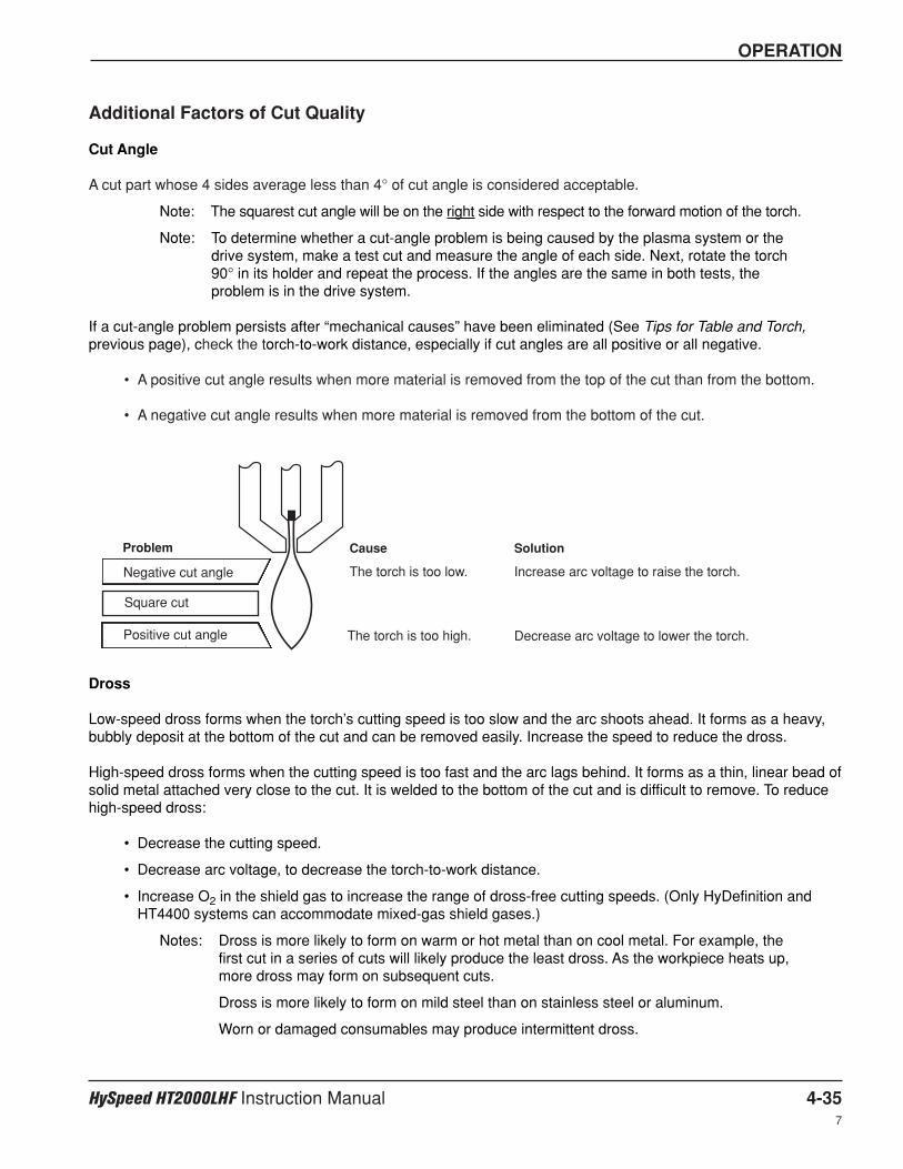
OPERATION
HySpeed HT2000LHF Instruction Manual 4-357
Additional Factors of Cut Quality
Cut Angle
A cut part whose 4 sides average less than 4° of cut angle is considered acceptable.
Note: The squarest cut angle will be on the right side with respect to the forward motion of the torch.
Note: To determine whether a cut-angle problem is being caused by the plasma system or thedrive system, make a test cut and measure the angle of each side. Next, rotate the torch90° in its holder and repeat the process. If the angles are the same in both tests, theproblem is in the drive system.
If a cut-angle problem persists after “mechanical causes” have been eliminated (See Tips for Table and Torch,previous page), check the torch-to-work distance, especially if cut angles are all positive or all negative.
• A positive cut angle results when more material is removed from the top of the cut than from the bottom.
• A negative cut angle results when more material is removed from the bottom of the cut.
Dross
Low-speed dross forms when the torch’s cutting speed is too slow and the arc shoots ahead. It forms as a heavy,bubbly deposit at the bottom of the cut and can be removed easily. Increase the speed to reduce the dross.
High-speed dross forms when the cutting speed is too fast and the arc lags behind. It forms as a thin, linear bead ofsolid metal attached very close to the cut. It is welded to the bottom of the cut and is difficult to remove. To reducehigh-speed dross:
• Decrease the cutting speed.
• Decrease arc voltage, to decrease the torch-to-work distance.
• Increase O2 in the shield gas to increase the range of dross-free cutting speeds. (Only HyDefinition andHT4400 systems can accommodate mixed-gas shield gases.)
Notes: Dross is more likely to form on warm or hot metal than on cool metal. For example, thefirst cut in a series of cuts will likely produce the least dross. As the workpiece heats up,more dross may form on subsequent cuts.
Dross is more likely to form on mild steel than on stainless steel or aluminum.
Worn or damaged consumables may produce intermittent dross.
Cause
The torch is too low.
The torch is too high.
Square cut
\
Solution
Increase arc voltage to raise the torch.
Decrease arc voltage to lower the torch.Positive cut angle
Negative cut angle
Problem
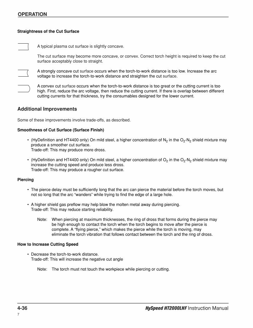
OPERATION
4-36 HySpeed HT2000LHF Instruction Manual7
Straightness of the Cut Surface
A typical plasma cut surface is slightly concave.
The cut surface may become more concave, or convex. Correct torch height is required to keep the cutsurface acceptably close to straight.
A strongly concave cut surface occurs when the torch-to-work distance is too low. Increase the arcvoltage to increase the torch-to-work distance and straighten the cut surface.
A convex cut surface occurs when the torch-to-work distance is too great or the cutting current is toohigh. First, reduce the arc voltage, then reduce the cutting current. If there is overlap between differentcutting currents for that thickness, try the consumables designed for the lower current.
Additional Improvements
Some of these improvements involve trade-offs, as described.
Smoothness of Cut Surface (Surface Finish)
• (HyDefinition and HT4400 only) On mild steel, a higher concentration of N2 in the O2-N2 shield mixture mayproduce a smoother cut surface. Trade-off: This may produce more dross.
• (HyDefinition and HT4400 only) On mild steel, a higher concentration of O2 in the O2-N2 shield mixture mayincrease the cutting speed and produce less dross. Trade-off: This may produce a rougher cut surface.
Piercing
• The pierce delay must be sufficiently long that the arc can pierce the material before the torch moves, butnot so long that the arc “wanders” while trying to find the edge of a large hole.
• A higher shield gas preflow may help blow the molten metal away during piercing. Trade-off: This may reduce starting reliability.
Note: When piercing at maximum thicknesses, the ring of dross that forms during the pierce maybe high enough to contact the torch when the torch begins to move after the pierce iscomplete. A “flying pierce,” which makes the pierce while the torch is moving, mayeliminate the torch vibration that follows contact between the torch and the ring of dross.
How to Increase Cutting Speed
• Decrease the torch-to-work distance. Trade-off: This will increase the negative cut angle
Note: The torch must not touch the workpiece while piercing or cutting.
HySpeed HT2000LHF Instruction Manual 5-16
Section 5
MAINTENANCE
IntroductionHypertherm assumes that the service personnel performing the troubleshooting testing are high-levelelectronic service technicians that have worked with high voltage electro-mechanical systems. Knowledgeof final isolation troubleshooting techniques is also assumed.
In addition to being technically qualified, maintenance personnel must perform all testing with safety inmind. Refer to the Safety section for operating precautions and warning formats.
If you need additional assistance or need to order parts, call our Customer Service or Technical Service groupslisted at the front of this manual.
WARNING
SHOCK HAZARD: The large chopper capacitors store large amounts of energy in the form ofelectric voltage. Even if the power is off, dangerous voltages exist at the capacitor terminals,on the chopper, and the diode heatsinks. Never discharge capacitors with a screwdriver orother implement…explosion, property damage and/or personal injury will result. Wait at leastfive minutes after turning the power supply off before touching the chopper or the capacitors.
Routine Maintenance
Torch and Torch Leads (See also Torch Coolant Draining at the end of this section)
Inspection
Inspect the torch and torch leads on a routine basis.
• The torch consumable parts and torch main body should always be inspected prior to cutting. Worn ordamaged parts can cause gas and water leaks which can affect the cut quality. Check for pitting and burnmarks on the consumable parts and replace them, if necessary. See Changing Consumable Parts inSection 4.
• Ensure that all connections are tight, but do not overtighten.
• The torch leads should be checked occasionally for cracking and damage.
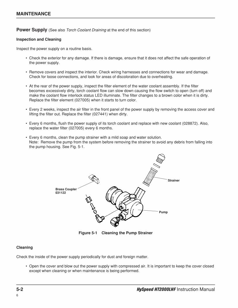
MAINTENANCE
5-2 HySpeed HT2000LHF Instruction Manual6
Power Supply (See also Torch Coolant Draining at the end of this section)
Inspection and Cleaning
Inspect the power supply on a routine basis.
• Check the exterior for any damage. If there is damage, ensure that it does not affect the safe operation ofthe power supply.
• Remove covers and inspect the interior. Check wiring harnesses and connections for wear and damage.Check for loose connections, and look for areas of discoloration due to overheating.
• At the rear of the power supply, inspect the filter element of the water coolant assembly. If the filterbecomes excessively dirty, torch coolant flow can slow down causing the flow switch to open (turn off) andmake the coolant flow interlock status LED illuminate. The filter changes to a brown color when it is dirty.Replace the filter element (027005) when it starts to turn color.
• Every 2 weeks, inspect the air filter in the front panel of the power supply by removing the access cover andlifting the filter out. Replace the filter (027441) when dirty.
• Every 6 months, flush the power supply of its torch coolant and replace with new coolant (028872). Also,replace the water filter (027005) every 6 months.
• Every 6 months, clean the pump strainer with a mild soap and water solution.Note: Remove the pump from the system before removing the strainer to avoid any debris from falling intothe pump housing. See Fig. 5-1.
Cleaning
Check the inside of the power supply periodically for dust and foreign matter.
• Open the cover and blow out the power supply with compressed air. It is important to keep the cover closedexcept when cleaning or when maintenance is being performed.
Figure 5-1 Cleaning the Pump Strainer
Brass Coupler031122
Strainer
Pump
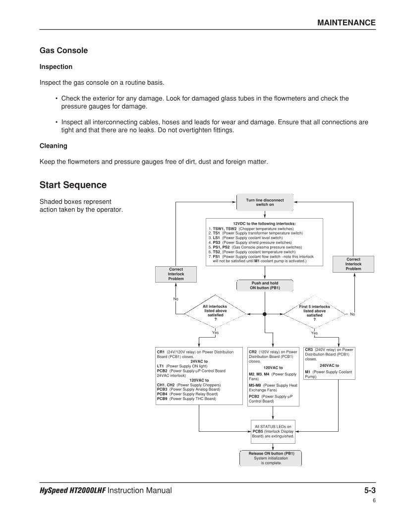
Turn line disconnect switch on
Push and holdON button (PB1)
Release ON button (PB1)System initialization
is complete.
12VDC to the following interlocks:1. TSW1, TSW2 (Chopper temperature switches)
2. TS1 (Power Supply transformer temperature switch)
3. LS1 (Power Supply coolant level switch)
4. PS3 (Power Supply shield pressure switches)
5. PS1,
,PS2 (Gas Console plasma pressure switches)
6. TS2 (Power Supply coolant temperature switch)
7. FS1 (Power Supply coolant flow switch – note this interlockwill not be satisfied until M1 coolant pump is activated.)
CR1 (24V/120V relay) on Power DistributionBoard (PCB1) closes.
24VAC toLT1 (Power Supply ON light)PCB2 (Power Supply-µP Control Board 24VAC interlock)
120VAC toCH1, CH2 (Power Supply Choppers)PCB3 (Power Supply Analog Board)PCB4 (Power Supply Relay Board)PCB9 (Power Supply THC Board)
CR2 (120V relay) on PowerDistribution Board (PCB1)closes.
120VAC to
M2, M3, M4 (Power SupplyFans)
M5-M8 (Power Supply HeatExchange Fans)
PCB2 (Power Supply-µPControl Board)
CR3 (240V relay) on PowerDistribution Board (PCB1)closes.
240VAC to
M1 (Power Supply CoolantPump)
All STATUS LEDs onPCB5 (Interlock DisplayBoard) are extinguished.
CorrectInterlockProblem
CorrectInterlockProblem
First 5 interlockslisted above
satisfied?
All interlockslisted above
satisfied?
No
No
Yes Yes
MAINTENANCE
HySpeed HT2000LHF Instruction Manual 5-36
Gas Console
Inspection
Inspect the gas console on a routine basis.
• Check the exterior for any damage. Look for damaged glass tubes in the flowmeters and check thepressure gauges for damage.
• Inspect all interconnecting cables, hoses and leads for wear and damage. Ensure that all connections aretight and that there are no leaks. Do not overtighten fittings.
Cleaning
Keep the flowmeters and pressure gauges free of dirt, dust and foreign matter.
Start Sequence
Shaded boxes representaction taken by the operator.
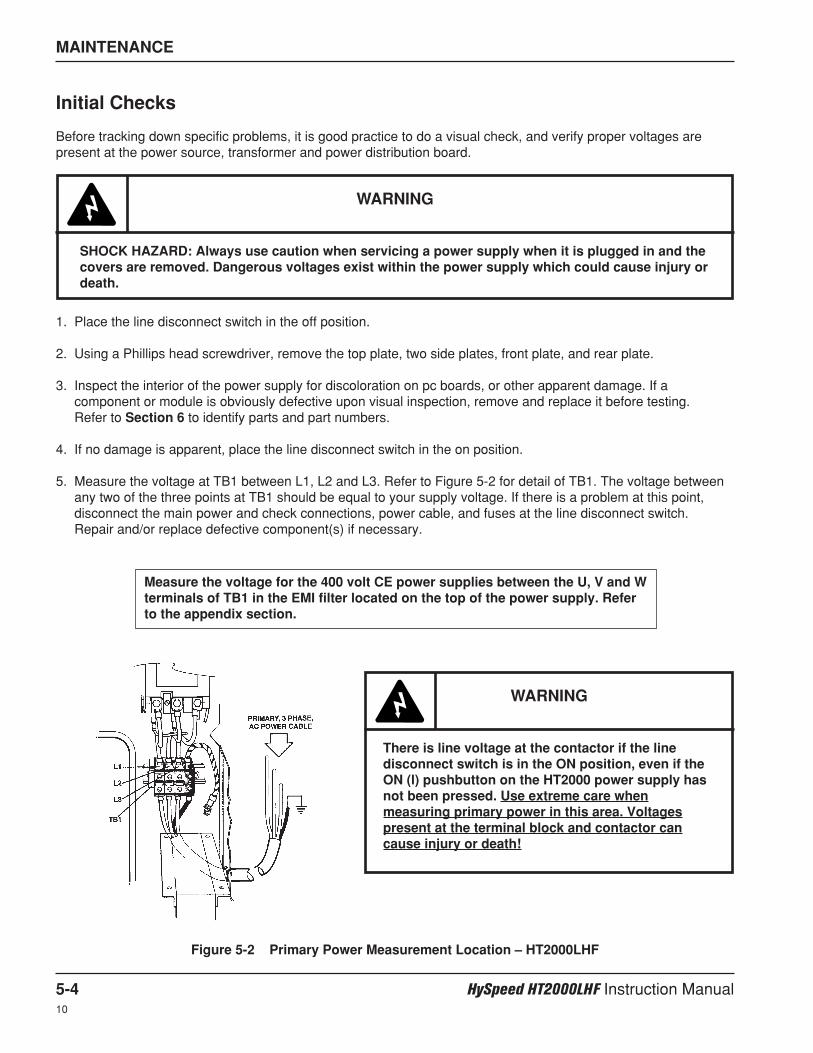
MAINTENANCE
5-4 HySpeed HT2000LHF Instruction Manual10
Initial Checks
Before tracking down specific problems, it is good practice to do a visual check, and verify proper voltages arepresent at the power source, transformer and power distribution board.
1. Place the line disconnect switch in the off position.
2. Using a Phillips head screwdriver, remove the top plate, two side plates, front plate, and rear plate.
3. Inspect the interior of the power supply for discoloration on pc boards, or other apparent damage. If acomponent or module is obviously defective upon visual inspection, remove and replace it before testing. Refer to Section 6 to identify parts and part numbers.
4. If no damage is apparent, place the line disconnect switch in the on position.
5. Measure the voltage at TB1 between L1, L2 and L3. Refer to Figure 5-2 for detail of TB1. The voltage betweenany two of the three points at TB1 should be equal to your supply voltage. If there is a problem at this point,disconnect the main power and check connections, power cable, and fuses at the line disconnect switch. Repair and/or replace defective component(s) if necessary.
WARNING
SHOCK HAZARD: Always use caution when servicing a power supply when it is plugged in and thecovers are removed. Dangerous voltages exist within the power supply which could cause injury ordeath.
Measure the voltage for the 400 volt CE power supplies between the U, V and Wterminals of TB1 in the EMI filter located on the top of the power supply. Referto the appendix section.
Figure 5-2 Primary Power Measurement Location – HT2000LHF
WARNING
There is line voltage at the contactor if the linedisconnect switch is in the ON position, even if theON (l) pushbutton on the HT2000 power supply hasnot been pressed. Use extreme care whenmeasuring primary power in this area. Voltagespresent at the terminal block and contactor cancause injury or death!
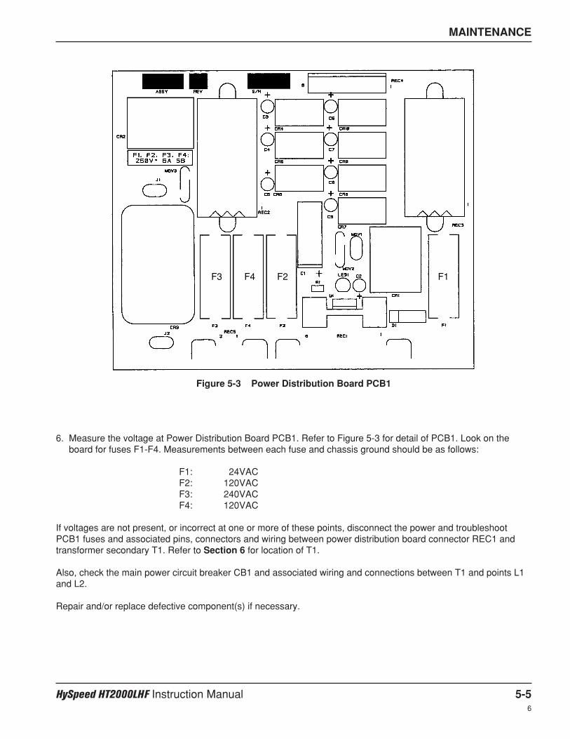
MAINTENANCE
HySpeed HT2000LHF Instruction Manual 5-56
Figure 5-3 Power Distribution Board PCB1
6. Measure the voltage at Power Distribution Board PCB1. Refer to Figure 5-3 for detail of PCB1. Look on theboard for fuses F1-F4. Measurements between each fuse and chassis ground should be as follows:
F1: 24VACF2: 120VACF3: 240VACF4: 120VAC
If voltages are not present, or incorrect at one or more of these points, disconnect the power and troubleshootPCB1 fuses and associated pins, connectors and wiring between power distribution board connector REC1 andtransformer secondary T1. Refer to Section 6 for location of T1.
Also, check the main power circuit breaker CB1 and associated wiring and connections between T1 and points L1and L2.
Repair and/or replace defective component(s) if necessary.
F2F4F3 F1
MAINTENANCE
5-6 HySpeed HT2000LHF Instruction Manual6
Troubleshooting
The troubleshooting section is presented by following normal operational sequence.
Before troubleshooting for specific problems, be sure that the unit passes Initial Checks as outlined earlier in thissection.
WARNING
SHOCK HAZARD: Always use caution when servicing a power supply when the covers areremoved. Dangerous voltages exist within the power supply which could cause injury or death. If questions or problems arise during servicing, call the Hypertherm Technical Services Departmentlisted at the front of this manual.
1. The green POWER ON pushbuttonswitch PB1 is pressed, but the fansare not operating and the greenPOWER ON indicator does notilluminate.
1.1. The POWER ON (I) PB1 pushbutton is defective.Check that the switch is operating correctly. The POWERON switch is normally open.
1.2. The POWER OFF (0) PB2 pushbutton is defective.Check that the switch is operating correctly. The POWEROFF switch is normally closed.
1.3. No jumper for PB2A and PB2B at TB5.TB5 terminals 1&2 and 4&5 need a jumper if there is nooptional remote I/O cable for switching the power supply onand off.
1.4. Associated wiring not making good contact.Check wiring and repair or replace, if necessary.
2. The green POWER ON pushbuttonswitch PB1 is pressed, the POWERON indicator illuminates, but thefans are not running.
2.1. CR2 on the power distribution board PCB1 is defective.Check that CR2 switches when the POWER ON pushbuttonis pressed. See Figure 5-3 for location of CR2. If CR2 isdefective, replace PCB1.
2.2. Connector from the power distribution board is not seatedsecurely.Check pins, connectors and associated wiring for continuity.Repair or replace, if necessary.
3. The green POWER ON pushbuttonswitch PB1 is pressed, the fans areoperating, but the green POWERON indicator does not illuminate.
3.1. Pushbutton PB1 was not held down for a long enoughperiod of time.Press and hold PB1 for a minimum of 5 seconds.
3.2. Relay CR1 on the power distribution board is defective.Check that CR1 switches when the POWER ON pushbuttonis pressed. See Figure 5-3 for location of CR1. If CR1 isdefective, replace PCB1.
Problem Possible Causes / Solutions
MAINTENANCE
HySpeed HT2000LHF Instruction Manual 5-76
4. The green POWER ON indicator isilluminated, the START command isgiven and the DC ON indicator isilluminated, but there is no highfrequency and no pilot arc.
4.1. There is no spark between the spark gap electrodes.Clean (with emery cloth), align and reset the electrode gapsto .020" (0.51 mm), if necessary. The electrode surfacesbetween the gaps should be flat. If the surfaces arerounded, replace and reset the gap.
• Inspect the high voltage transformer T3 in the powersupply for signs of overheating. See Figure 6-7 forlocation of T3 . Replace T3 if it is overheating.
• Check for 120VAC at T3 after the START command isgiven.
• If there is no 120VAC at T3, use wiring diagrams inSection 7 to check pins, connectors and associatedwiring from T3 to relay board PCB4. If connections areOK, there may be a problem with either PCB4 or PCB2.
• If there is 120VAC at T3 , shut down the system andremove capacitors C4, C5 and C6. (See Figure 6-7 forlocation of C4, C5 and C6) Restart the system and lookfor a faint spark across the gaps.
• If a spark is not observed at the gaps, replace T3. If thereis a spark, shut down system, and replace capacitors C4,C5 and C6. (Always replace all the capacitors.)
4.2. There is no high frequency at the torch.Check for a shorted torch, or loose lead connections.Replace the torch or tighten the lead connections.
Problem Possible Causes / Solutions
3.3. One or more of the STATUS LEDs remains illuminated,indicating a fault condition.To troubleshoot STATUS fault conditions, see Status LEDTroubleshooting later in this section.
5. The green POWER ON indicator isilluminated, the torch STARTcommand is given and the DC ONindicator illuminates, and there ishigh frequency, but there is nopilot arc.
5.1. Pilot arc relay CR1 is not closing.See if the CR1 relay contacts close after the STARTcommand is given. See Figure 6-7 for location of CR1. IfCR1 does not close:
• With an AC voltmeter across the relay, see if 120VAC iscoming from PCB4 after the START command is given.
• If there is no 120VAC, check connectors, terminals, pins,and associated wiring to PCB4.
• If wiring is OK, there is a problem either with PCB4 orPCB2.

MAINTENANCE
5-8 HySpeed HT2000LHF Instruction Manual6
Problem Possible Causes / Solutions
5.2. Pilot arc relay CR1 is defective.If there is 120VAC across the relay (see previous steps),and CR1 does not close, replace CR1.
5.3. Main contactor (CON1) or PCB4 is defective.
• With an AC voltmeter, see if there is 120VAC at contactorCON1 after the START command is given. If there is no120VAC, check pins, connectors and associated wiringfrom CON1 to PCB4.
• If wiring is OK, PCB4 or PCB2 may be defective.
• If there is 120VAC at CON1 as described above, measurethe voltage between secondary terminals of the maintransformer T2 after the START command is given. Thevoltage between any two of the three points connected toeach chopper input should be equal to about 200VAC.
If there is no voltage at any of the above points, replaceCON1.
If there is voltage at some but not all of the above points,check wiring and connections to and from T2. If wiringchecks out OK, return to Initial Checks section and repeatsteps 1-5.
5.4. Choppers are defective or not functioning.See Chopper Module Test Procedure later in this section.
6. The unit stops cutting during cut, orcuts poorly.
6.1. The work cable is not connected or it is broken.Connect or repair the work cable.
6.2. Arc not transferring to workpiece.Check the work cable connection to the workpiece. Goodcontact must be made in order for the arc to transfer.
6.3. There is insufficient air or gas pressure.Check the gas inlet pressures and the plasma and shieldgas pressures in TEST and RUN modes as specified in theCut Charts.
6.4. Torch is getting insufficient current.Check the arc current setting in the Cut Charts for the typeand thickness of metal you are cutting.
6.5. The power supply has overheated.Shut down the system and wait for the power supply to cooldown. If the power supply will not restart, see Status LEDTroubleshooting guide later in this section.
6.6. Choppers are defective or not functioning.See Chopper Module Test Procedure later in this section.
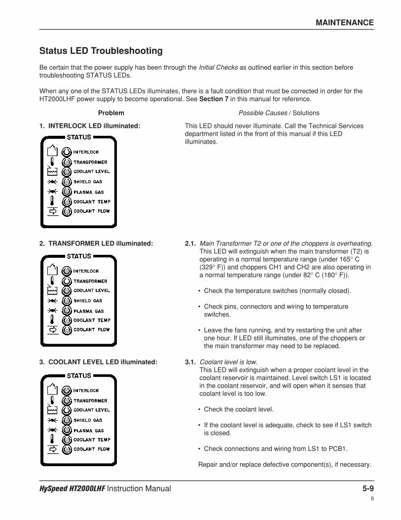
MAINTENANCE
HySpeed HT2000LHF Instruction Manual 5-96
Problem Possible Causes / Solutions
Status LED Troubleshooting
Be certain that the power supply has been through the Initial Checks as outlined earlier in this section beforetroubleshooting STATUS LEDs.
When any one of the STATUS LEDs illuminates, there is a fault condition that must be corrected in order for theHT2000LHF power supply to become operational. See Section 7 in this manual for reference.
1. INTERLOCK LED illuminated: This LED should never illuminate. Call the Technical Servicesdepartment listed in the front of this manual if this LEDilluminates.
2. TRANSFORMER LED illuminated: 2.1. Main Transformer T2 or one of the choppers is overheating.This LED will extinguish when the main transformer (T2) isoperating in a normal temperature range (under 165° C(329° F)) and choppers CH1 and CH2 are also operating ina normal temperature range (under 82° C (180° F)).
• Check the temperature switches (normally closed).
• Check pins, connectors and wiring to temperatureswitches.
• Leave the fans running, and try restarting the unit afterone hour. If LED still illuminates, one of the choppers orthe main transformer may need to be replaced.
3. COOLANT LEVEL LED illuminated: 3.1. Coolant level is low.This LED will extinguish when a proper coolant level in thecoolant reservoir is maintained. Level switch LS1 is locatedin the coolant reservoir, and will open when it senses thatcoolant level is too low.
• Check the coolant level.
• If the coolant level is adequate, check to see if LS1 switchis closed.
• Check connections and wiring from LS1 to PCB1.
Repair and/or replace defective component(s), if necessary.
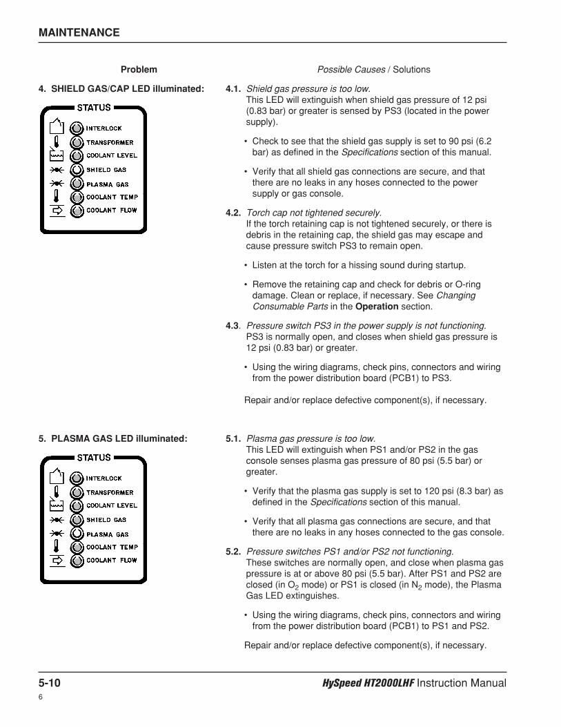
MAINTENANCE
5-10 HySpeed HT2000LHF Instruction Manual6
Problem Possible Causes / Solutions
5. PLASMA GAS LED illuminated: 5.1. Plasma gas pressure is too low.This LED will extinguish when PS1 and/or PS2 in the gasconsole senses plasma gas pressure of 80 psi (5.5 bar) orgreater.
• Verify that the plasma gas supply is set to 120 psi (8.3 bar) asdefined in the Specifications section of this manual.
• Verify that all plasma gas connections are secure, and thatthere are no leaks in any hoses connected to the gas console.
5.2. Pressure switches PS1 and/or PS2 not functioning.These switches are normally open, and close when plasma gaspressure is at or above 80 psi (5.5 bar). After PS1 and PS2 areclosed (in O2 mode) or PS1 is closed (in N2 mode), the PlasmaGas LED extinguishes.
• Using the wiring diagrams, check pins, connectors and wiringfrom the power distribution board (PCB1) to PS1 and PS2.
Repair and/or replace defective component(s), if necessary.
4. SHIELD GAS/CAP LED illuminated: 4.1. Shield gas pressure is too low.This LED will extinguish when shield gas pressure of 12 psi(0.83 bar) or greater is sensed by PS3 (located in the powersupply).
• Check to see that the shield gas supply is set to 90 psi (6.2bar) as defined in the Specifications section of this manual.
• Verify that all shield gas connections are secure, and thatthere are no leaks in any hoses connected to the powersupply or gas console.
4.2. Torch cap not tightened securely.If the torch retaining cap is not tightened securely, or there isdebris in the retaining cap, the shield gas may escape andcause pressure switch PS3 to remain open.
• Listen at the torch for a hissing sound during startup.
• Remove the retaining cap and check for debris or O-ringdamage. Clean or replace, if necessary. See ChangingConsumable Parts in the Operation section.
4.3. Pressure switch PS3 in the power supply is not functioning.PS3 is normally open, and closes when shield gas pressure is12 psi (0.83 bar) or greater.
• Using the wiring diagrams, check pins, connectors and wiringfrom the power distribution board (PCB1) to PS3.
Repair and/or replace defective component(s), if necessary.

MAINTENANCE
HySpeed HT2000LHF Instruction Manual 5-116
Problem Possible Causes / Solutions
6. COOLANT TEMP LED illuminated: 6.1. Coolant is too hot.This LED will extinguish when temperature switch TS2senses that the temperature of coolant in the coolantreservoir is under 160° F (71° C).
• Check to see if the water coolant is above 160° F (71° C).
• Check to see if TS2 (located in the coolant reservoir) isopen. TS2 is normally closed, and is opened when atemperature above 160° F (71° C) is reached.
• Using the wiring diagrams, check pins, wires andconnections from TS2 to PCB1.
Repair and/or replace defective component(s), if necessary.
7. COOLANT FLOW LED illuminated: 7.1. Coolant flow is restricted.This LED will extinguish when flowswitch FS1 senses acoolant flow of at least 0.5 gpm (1.9 lpm) to the torch. FS1is a normally open switch that closes when a flow greaterthan 0.5 gpm (1.9 lpm) is sensed. See Coolant Flow TestProcedure later in this section to troubleshoot coolant flowproblems.
Note: Coolant flow LED illuminates when the line disconnectswitch is turned ON because coolant reservoir pump M2 isnot activated until the power supply POWER ON (PB1) ispressed.
MAINTENANCE
5-12 HySpeed HT2000LHF Instruction Manual6
Chopper Module Test Procedure
Note: Take voltages with a digital multimeter capable of storing min. and max. readings.
1. Turn all power to the power supply OFF.Disconnect the mating receptacles in the power supply to disable the high frequency transformer T3. See Figure 6-7 for location of T3.
2. Remove large fuses F1 and F2. Check to see if the fuses are open.
3. Place the positive lead to the + side of the bridge and the negative lead to the – side of the bridge. See Figure 5-4. Note that actual connection points are hidden by cap support bracket in Figure 5-4.
4. Turn power to the power supply ON, and start the system up. After the START command has been given, checkthe voltage. The input to the chopper at these points should be about +280 VDC. If the input is OK andcorresponding fuse F1 or F2 was blown, replace the chopper module.If there is no +280 VDC input, check input to bridge for shorts. Also, check contactor (CON1), connections andassociated wiring to the contactor. Repair and/or replace defective component(s) if necessary.
5. If the voltage from above step is +280 VDC and corresponding fuse is not blown, check output of CH1 byplacing the positive lead of the voltmeter at point + WORK on the chopper module (wire #48A) and negativelead at point - TORCH (wire #39A). (Check the output of CH2 by placing the leads of the voltmeter at thecorresponding points on the other chopper module.)
6. Turn the system on and press the START command. After the START command has been given, check thevoltage. If the output from each chopper at these points is +280 VDC, then the choppers are OK.
7. If the chopper does not output +280 VDC, check to see if the LED1 logic power light is illuminated. If LED1 isextinguished, check if 120V is going to JP6. If there is no 120V at JP6, check wiring back to the powerdistribution board. Repair or replace defective component(s), if necessary. Also check to see if LED3 is turninggreen when enabled (normal condition). If LED1 is illuminated and LED3 is red when enabled (fault condition),then make sure that JP9 is seated properly.
8. If the chopper still does not output 280V after completing step 7, there may be a problem with the control signalor the chopper module. The chopper drive signal comes through the analog board PCB3 as an analog levelfrom 0 to +8 VDC, which varies the duty cycle and subsequent output current of the chopper. These analogsignals are on pins 3&4 REC1 of PCB3 for CH1, and 5&6 REC1 for CH2.
WARNING
SHOCK HAZARD: Use extreme care when working near the chopper modules. The large choppercapacitors store large amounts of energy in the form of electric voltage. Even if the power is off,dangerous voltages exist at the capacitor terminals, on the chopper, and the diode heatsinks.Never discharge capacitors with a screwdriver or other implement…explosion, property damageand/or personal injury will result.
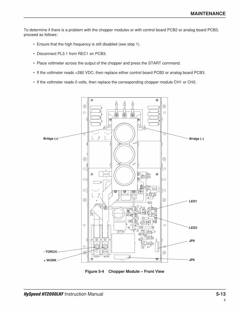
MAINTENANCE
HySpeed HT2000LHF Instruction Manual 5-136
To determine if there is a problem with the chopper modules or with control board PCB2 or analog board PCB3,proceed as follows:
• Ensure that the high frequency is still disabled (see step 1).
• Disconnect PL3.1 from REC1 on PCB3.
• Place voltmeter across the output of the chopper and press the START command.
• If the voltmeter reads +280 VDC, then replace either control board PCB2 or analog board PCB3.
• If the voltmeter reads 0 volts, then replace the corresponding chopper module CH1 or CH2.
Figure 5-4 Chopper Module – Front View
Bridge (+)
- TORCH
+ WORK
Bridge (–)
LED3
LED1
JP9
JP6
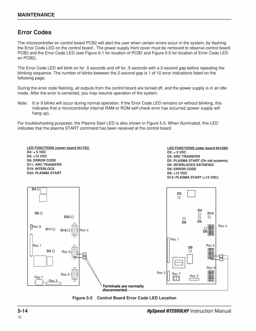
MAINTENANCE
5-14 HySpeed HT2000LHF Instruction Manual10
Error Codes
The microcontroller on control board PCB2 will alert the user when certain errors occur in the system, by flashingthe Error Code LED on the control board . The power supply front cover must be removed to observe control boardPCB2 and the Error Code LED (see Figure 6-1 for location of PCB2 and Figure 5-5 for location of Error Code LEDon PCB2).
The Error Code LED will blink on for .5 seconds and off for .5 seconds with a 2-second gap before repeating theblinking sequence. The number of blinks between the 2-second gap is 1 of 10 error indications listed on thefollowing page.
During the error code flashing, all outputs from the control board are turned off, and the power supply is in an idlemode. After the error is corrected, you may resume operation of the system.
Note: 8 or 9 blinks will occur during normal operation. If the Error Code LED remains on without blinking, thisindicates that a microcontroller internal RAM or ROM self-check error has occurred (power supply will hang up).
For troubleshooting purposes, the Plasma Start LED is also shown in Figure 5-5. When illuminated, this LEDindicates that the plasma START command has been received at the control board.
Figure 5-5 Control Board Error Code LED Location
D22
D4
D5
D6
D19 Rec 4
Rec 5
Rec 6
Rec 3Rec 7
Rec 8
Rec 1
D11
Terminals are normallydisconnected.
LED FUNCTIONS (newer board 041762)D4: + 5 VDCD5: +12 VDCD6: ERROR CODED11: ARC TRANSFERD19: INTERLOCKD22: PLASMA START
LED FUNCTIONS (older board 041590)D3: + 5 VDCD4: ARC TRANSFERD5: PLASMA START (On old systems)D6: INTERLOCKS SATISFIEDD8: ERROR CODED9: +12 VDCD14: PLASMA START (+12 VDC)
D3
D8
D4
D5
D6
D9
Rec 4
Rec 5
Rec 6
Rec 3Rec 7Rec 2
Rec 1
D14
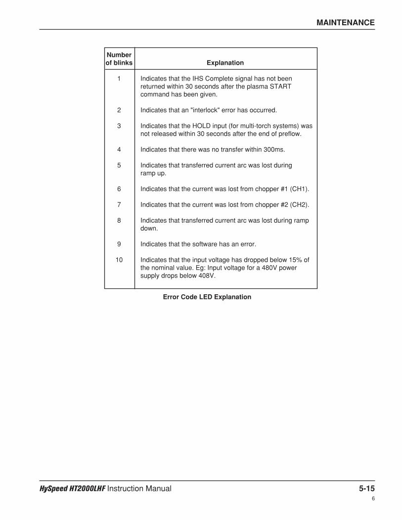
MAINTENANCE
HySpeed HT2000LHF Instruction Manual 5-156
Numberof blinks Explanation
1 Indicates that the IHS Complete signal has not beenreturned within 30 seconds after the plasma STARTcommand has been given.
2 Indicates that an "interlock" error has occurred.
3 Indicates that the HOLD input (for multi-torch systems) wasnot released within 30 seconds after the end of preflow.
4 Indicates that there was no transfer within 300ms.
5 Indicates that transferred current arc was lost during ramp up.
6 Indicates that the current was lost from chopper #1 (CH1).
7 Indicates that the current was lost from chopper #2 (CH2).
8 Indicates that transferred current arc was lost during rampdown.
9 Indicates that the software has an error.
10 Indicates that the input voltage has dropped below 15% ofthe nominal value. Eg: Input voltage for a 480V powersupply drops below 408V.
Error Code LED Explanation
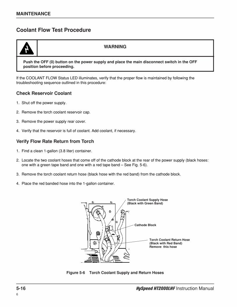
MAINTENANCE
5-16 HySpeed HT2000LHF Instruction Manual6
Coolant Flow Test Procedure
If the COOLANT FLOW Status LED illuminates, verify that the proper flow is maintained by following thetroubleshooting sequence outlined in this procedure:
Check Reservoir Coolant
1. Shut off the power supply.
2. Remove the torch coolant reservoir cap.
3. Remove the power supply rear cover.
4. Verify that the reservoir is full of coolant. Add coolant, if necessary.
Verify Flow Rate Return from Torch
1. Find a clean 1-gallon (3.8 liter) container.
2. Locate the two coolant hoses that come off of the cathode block at the rear of the power supply (black hoses:one with a green tape band and one with a red tape band – See Fig. 5-6).
3. Remove the torch coolant return hose (black hose with the red band) from the cathode block.
4. Place the red banded hose into the 1-gallon container.
WARNING
Push the OFF (0) button on the power supply and place the main disconnect switch in the OFFposition before proceeding.
Torch Coolant Supply Hose(Black with Green Band)
Cathode Block
Torch Coolant Return Hose (Black with Red Band)Remove this hose
Figure 5-6 Torch Coolant Supply and Return Hoses
MAINTENANCE
HySpeed HT2000LHF Instruction Manual 5-176
Check Pump, Motor and Solenoid Valve (V1)
1. If the coolant is not flowing, check to see if the motor and valve V1 are getting 240VAC. Note: The 240VACrelay (CR3) on PCB1 will not close until the first 5 interlocks (STATUS) indicators are satisfied. (See StartSequence flowchart earlier in this section.)
2. If the motor, pump and valve all seem to be functioning and the flow is not sufficient, replace the pump andmotor assembly.
5. Turn the power supply power on.
6. Hold down the ON (I) button on the power supply.
7. Start timing for 30 seconds, and then release the button.
8. Verify that the container is 1/2 full. If not 1/2 full, repeat this test and time discharge for 1 minute. After 1 minuteverify that the container is at least 3/4 full.
8.1. If the 1-gallon container is less than 3/4 full after step 8, go to Verify Flow Rate to Torch.
8.2. If the 1-gallon container is at least 3/4 full after step 8, the problem is either with the flow switch or theparticulate filter.
• Remove the filter element and re-connect the coolant hose to the cathode block on the rear of the powersupply.
• Start the power supply. If the COOLANT FLOW LED remains illuminated, replace the flow switch. If the LEDdoes not illuminate, replace the filter element.
Verify Flow Rate to Torch
1. Press the power supply OFF (0) button and place the main disconnect switch to the OFF position.
2. Remove the torch consumables.
3. Replace only the retaining cap on the torch. (Do not replace the electrode, nozzle and swirl ring back in thetorch.)
4. Place the empty 1-gallon container under the torch.
5. Turn the power back on and press and hold down the power supply ON (I) button.
6. Start timing for 1 minute. The torch should deliver at least 1 gallon (3.8 liters) of fluid in 1 minute.
7. If the torch delivers at least 1 gallon (3.8 liters) of fluid per minute, then the flow rate to the torch is OK. Replacethe torch. If the torch does not deliver at least 1 gallon (3.8 liters) of fluid per minute, go to Check Pump, Motor,and Solenoid Valve (V1).
8. If replacing the torch does not satisfy the flow switch, then replace the torch leads.
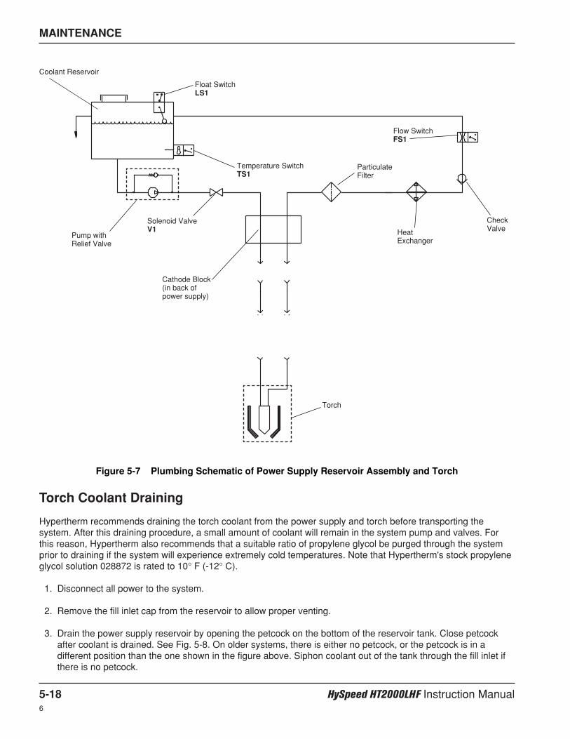
MAINTENANCE
5-18 HySpeed HT2000LHF Instruction Manual6
Torch Coolant Draining
Hypertherm recommends draining the torch coolant from the power supply and torch before transporting thesystem. After this draining procedure, a small amount of coolant will remain in the system pump and valves. Forthis reason, Hypertherm also recommends that a suitable ratio of propylene glycol be purged through the systemprior to draining if the system will experience extremely cold temperatures. Note that Hypertherm's stock propyleneglycol solution 028872 is rated to 10° F (-12° C).
1. Disconnect all power to the system.
2. Remove the fill inlet cap from the reservoir to allow proper venting.
3. Drain the power supply reservoir by opening the petcock on the bottom of the reservoir tank. Close petcockafter coolant is drained. See Fig. 5-8. On older systems, there is either no petcock, or the petcock is in adifferent position than the one shown in the figure above. Siphon coolant out of the tank through the fill inlet ifthere is no petcock.
Figure 5-7 Plumbing Schematic of Power Supply Reservoir Assembly and Torch
Cathode Block(in back ofpower supply)
HeatExchanger
CheckValve
Flow SwitchFS1
Solenoid ValveV1
ParticulateFilter
Float SwitchLS1
Coolant Reservoir
Temperature Switch TS1
Torch
Pump withRelief Valve
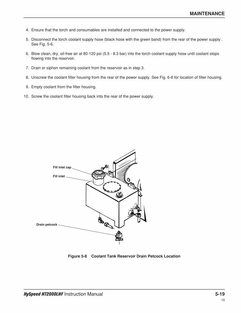
MAINTENANCE
HySpeed HT2000LHF Instruction Manual 5-1910
Drain petcock
Figure 5-8 Coolant Tank Reservoir Drain Petcock Location
Fill inlet
Fill inlet cap
4. Ensure that the torch and consumables are installed and connected to the power supply.
5. Disconnect the torch coolant supply hose (black hose with the green band) from the rear of the power supply .See Fig. 5-6.
6. Blow clean, dry, oil-free air at 80-120 psi (5.5 - 8.3 bar) into the torch coolant supply hose until coolant stopsflowing into the reservoir.
7. Drain or siphon remaining coolant from the reservoir as in step 3.
8. Unscrew the coolant filter housing from the rear of the power supply. See Fig. 6-8 for location of filter housing.
9. Empty coolant from the filter housing.
10. Screw the coolant filter housing back into the rear of the power supply.
MAINTENANCE
5-20 HySpeed HT2000LHF Instruction Manual10
Preventive Maintenance
Introduction
Deteriorating consumable parts life is frequently one of the first symptoms to indicate that something is wrong witha plasma system. Reduced parts life dramatically increases operating costs for two reasons: first, and perhapsmost obvious, shorter consumable life means that the end user will have to use more consumables to cut the sameamount of metal. The second, and even more important factor, is that shorter consumable life means that the enduser must shut down his cutting operation to change consumables more often. In an average cutting operation,labor and overhead can account for over 80% of the cost of cutting, so improved productivity, in the form of lessdowntime, can reduce cutting costs dramatically.
Proper maintenance often eliminates the problems that lead to shortened consumables life. Since the basicpremise behind the purchase of a Hypertherm plasma system is reduced cutting costs and increased productivity,maintaining a system in proper operating condition is a key to ensuring customer satisfaction.
The Preventive Maintenance Protocol is intended to be simple to follow. After you have performed it a few times,you should expect to take approximately 3 hours to complete it for each individual plasma system involved.
Hypertherm wants to meet or exceed our customers’ expectations. We hope that this booklet will help you meet orexceed those customers’ expectations.
Preventive maintenance protocol
The following protocol covers the basic elements of a Hypertherm mechanized plasma system. These basicelements apply broadly to all our mechanized systems, although certain specific components, such as the high-frequency console or the coolant system, are not present in all mechanized systems. The protocol may thereforevary slightly from a MAX100 to an HT2000, for example, and as we move through the protocol, we have tried tonote where certain steps would not be necessary for certain systems.
It is important to have available for reference a copy of the appropriate manual for the Hypertherm system to bemaintained.
If inspection suggests that a component is worn and might require replacement, and you would like confirmation ofyour recommendation, please contact Hypertherm's Technical Service department.
The power supply
When performing preventive maintenance in any plasma system power supply, it is critical to turn off power to thepower supply at the source. Extreme electrical hazard is present in the power supply and at the torch. Pleaseconsult the manual for a complete list of safety precautions.
1. With power to the power supply off, remove all side panels and inspect for accumulated dust. Usingcompressed air, blow out the inside of the power supply to remove dust and particulates.
2. Inspect wiring harnesses and connections for any wear or damage. Check for loose connections and look forany discoloration that might indicate overheating. If this condition is observed, contact Hypertherm TechnicalService.
3. Inspect the main contactor for excessive pitting on the contacts, characterized by a blackened, rough surfaceon any of the contacts. If this condition exists, replacement should be recommended.
4. If the plasma system has an air filter in the front panel of the power supply, inspect the air filter andrecommend replacement if dirty.
5. Inspect the pilot arc relay (CR1) for excessive pitting on the contacts, characterized by a roughened, blacksurface. Recommend replacement if necessary.

MAINTENANCE
HySpeed HT2000LHF Instruction Manual 5-2110
Coolant system
6. If the plasma equipment in question has a built-in coolant system, inspect the filter element of the coolantsystem which is located at the rear of the power supply. If the filter has begun to turn a brownish color,replacement should be recommended. For HyDefinition systems, a de-ionizing filter should be used. Refer tothe manual for proper part numbers. If the system is a MAX200 or HT2000, a particle filter should be used.
7. Perform a coolant flow test on the system. For MAX200, HT2000, HD1070 and HD3070 systems, flow shouldbe at least 0.75 gpm (2.8 l/min) on the return line. When testing systems with external water chillers, therequired coolant flow varies according to different size pumps. Refer to appropriate manuals.
Check for coolant leaks. Primary locations to inspect are: 1) the back of the power supply; 2) at the high-frequency console, if applicable; and, 3) at the torch main body. Check the holding tank for dirt andparticulates. Verify that proper Hypertherm coolant is being used.
Torch main body
8. If the torch contains a water tube for electrode cooling, check the water tube to ensure that it is straight andhas no pitting on the end.
9. Check the current ring inside the torch main body. The current ring should be smooth and not pitted. If slightpitting is seen, contact Hypertherm Technical Service to assess the likelihood that the torch could be repaired.If no pitting is observed, clean the current ring with a clean cotton swab and clean water. Do not use alcohol.Pitting on the current ring generally indicates improper maintenance (i.e. lack of regular cleaning).
10. Clean all threads on the front end of the torch head with clean water and a cotton swab, pipe cleaner or cleancloth. Do not use alcohol. Damage to the threads usually results from not properly cleaning the torch andretaining cap threads, so that dirt and particulates accumulate in the threads.
11. Inspect the torch insulator for cracks. Replacement of the torch should be recommended if cracks are found.
12. Inspect all o-rings on the torch body and consumables. Make sure that the correct amount of lubricant is beingapplied to these o-rings. Too much lubricant may obstruct gas flows.
13. Ensure that the retaining or shield cap is tightened securely to the torch main body.
14. Check all hose fittings at the rear of the torch for wear. Damage to the fitting threads may indicate thatovertightening has occurred.
15. Ensure that all connections between the torch and torch leads are tight, but do not overtighten.
When removing consumables, always place them on a clean, dry, oil-free surface, since dirty consumablesmay cause the torch to malfunction.
Gas flows
16. Check the plumbing from the gas supply source, as follows:
A. Remove and plug the oxygen inlet gas fitting at the gas console.
B. Pressurize the gas system at the source to 8.3 bar (120 psi).
C. Close the gas supply valve at the source. Watch for a pressure drop. If the supply line from the source is ahose, there may be a 0.3 to 0.5 bar (5 to 7 psi) drop due to stretch.
D. If the pressure continues to drop, find the leaks in the system.
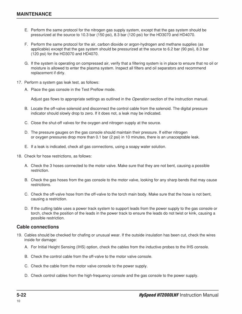
MAINTENANCE
5-22 HySpeed HT2000LHF Instruction Manual10
E. Perform the same protocol for the nitrogen gas supply system, except that the gas system should bepressurized at the source to 10.3 bar (150 psi), 8.3 bar (120 psi) for the HD3070 and HD4070.
F. Perform the same protocol for the air, carbon dioxide or argon-hydrogen and methane supplies (asapplicable) except that the gas system should be pressurized at the source to 6.2 bar (90 psi), 8.3 bar(120 psi) for the HD3070 and HD4070.
G. If the system is operating on compressed air, verify that a filtering system is in place to ensure that no oil ormoisture is allowed to enter the plasma system. Inspect all filters and oil separators and recommendreplacement if dirty.
17. Perform a system gas leak test, as follows:
A. Place the gas console in the Test Preflow mode.
Adjust gas flows to appropriate settings as outlined in the Operation section of the instruction manual.
B. Locate the off-valve solenoid and disconnect the control cable from the solenoid. The digital pressureindicator should slowly drop to zero. If it does not, a leak may be indicated.
C. Close the shut-off valves for the oxygen and nitrogen supply at the source.
D. The pressure gauges on the gas console should maintain their pressure. If either nitrogenor oxygen pressures drop more than 0.1 bar (2 psi) in 10 minutes, there is an unacceptable leak.
E. If a leak is indicated, check all gas connections, using a soapy water solution.
18. Check for hose restrictions, as follows:
A. Check the 3 hoses connected to the motor valve. Make sure that they are not bent, causing a possiblerestriction.
B. Check the gas hoses from the gas console to the motor valve, looking for any sharp bends that may causerestrictions.
C. Check the off-valve hose from the off-valve to the torch main body. Make sure that the hose is not bent,causing a restriction.
D. If the cutting table uses a power track system to support leads from the power supply to the gas console ortorch, check the position of the leads in the power track to ensure the leads do not twist or kink, causing apossible restriction.
Cable connections
19. Cables should be checked for chafing or unusual wear. If the outside insulation has been cut, check the wiresinside for damage:
A. For Initial Height Sensing (IHS) option, check the cables from the inductive probes to the IHS console.
B. Check the control cable from the off-valve to the motor valve console.
C. Check the cable from the motor valve console to the power supply.
D. Check control cables from the high-frequency console and the gas console to the power supply.
HySpeed HT2000LHF Instruction Manual 5-2310
High-frequency console (if applicable)
20. Open the cover and inspect the interior for condensation or the accumulation of dust and particulates. If dustand particulates are present, blow out the unit with compressed air. If moisture is present, dry the inside of theconsole with a cloth and contact Hypertherm Technical Service for recommended action.
21. Inspect the spark gap subassembly. Inspect the 3 electrodes. Verify that the electrodes are 0.508 mm (0.020")apart and that they are clean and the ends are flat. File the electrodes clean with a diamond file if necessary.Ensure that the wiring connections to the spark gap subassembly are secure. Check that the console doorsare properly closed.
22. Inspect the torch leads. Ensure that they are fastened tightly to the outside of the high-frequency console.
System grounding
23. Verify that all components of the system are individually grounded to a driven earth ground, as described in theinstruction manual.
A. All metal enclosures, such as the power supply, high-frequency console and gas console, should beconnected individually to a ground point. These connections should be made with 10 mm2 (#8 AWG) wire(USA), or equivalent-size wire.
24. Check the connection from the cutting table to the workpiece (+) lead. Particularly inspect where the positive(+) lead connects to the cutting table to ensure that it is a good, clean connection. A poor connection maycause arc transfer problems.
MAINTENANCE

5-24 HySpeed HT2000LHF Instruction Manual10
Preventive Maintenance Master Schedule
Daily:
• Verify proper inlet gas pressure.
• Verify proper gas flow settings. – Mandatory at every consumable change.
• Verify proper coolant pressures and temperatures. – Water chillers only.
• Inspect torch and replace consumables as needed.
Weekly:
Week Jan Feb March April May June July Aug Sept Oct Nov Dec
1
2
3
4
5
Monthly:
Jan Feb March April May June July Aug Sept Oct Nov Dec
Bi-Annually:
Year 1st Service 2nd Service
• Clean power supply with dry, oil free compressed air or vacuum.
• Verify cooling fans are working properly.
• Clean torch threads and current ring.
• Verify proper coolant level.
• Complete systems check per the preventive maintenance protocol.
Annually:
Year
• Complete systems check per the preventive maintenance protocol.
• Replace service parts per the service part replacement schedule.
• Complete systems check per the preventive maintenance protocol.
• Replace service parts per the service part replacement schedule.

HySpeed HT2000LHF Instruction Manual 5-2510
Gas flows (cont.)�P �NP 17. Perform gas leak test
A. Oxygen pressure drop at ____________psi in 10 minutes ( ____________ bar)
B. Nitrogen pressure drop at ____________psi in 10 minutes ( ____________ bar)
�P �NP 18. Inspect for hose restrictions�P �NP A. Motor valve hoses�P �NP B. Gas console to motor valve�P �NP C. Off-valve to torch body�P �NP D. Hoses in power track
Cable connections�P �NP 19. Inspect cables
�P �NP A. From IHS probes to IHS console�P �NP B. Control cable from off-valve to
motor valve console�P �NP C. From motor valve console to
power supply�P �NP D. From high-frequency console
and gas console to power supply
High-frequency console�P �NP 20. Inspect for moisture, dust and
particulates�P �NP 21. Inspect spark gap subassembly
�P �NP A. Electrode gap range _______ to _______
�P �NP 22. Inspect torch leads
System grounding�P �NP 23. Inspect for proper system
component grounding�P �NP 24. Inspect connection from cutting
table to workpiece (+) lead
Power supply�P �NP 1. Inspect for particulates and blow out�P �NP 2. Inspect wiring harnesses�P �NP 3. Inspect main contactor�P �NP 4. Inspect air filter on front of system�P �NP 5. Inspect pilot arc relay
Coolant system�P �NP 6. Inspect filter element�P �NP 7. Perform coolant flow test
A. Coolant flow checked at _________gallons per minute ( _________ l/min)
Torch main body�P �NP 8. Inspect water tube�P �NP 9. Inspect current ring�P �NP 10. Clean threads on torch front end�P �NP 11. Inspect Vespel torch insulator�P �NP 12. Inspect torch and consumable o-rings�P �NP 13. Verify proper fit of retaining or shield cap�P �NP 14. Inspect hose fittings�P �NP 15. Inspect torch-to-torch-lead connections
Gas flows�P �NP 16. Inspect plumbing from gas supply
�P �NP A. Oxygen�P �NP B. Nitrogen�P �NP C. Air�P �NP D. CO2
�P �NP E. Argon-Hydrogen�P �NP F. Methane�P �NP G. Inspect compressed air filter system
Preventive Maintenance Protocol ChecklistCustomer:Location:Contact:Date:
Hypertherm system:System serial #:
System arc hours: (if equipped with an hour meter)
Comments P – Performed NP – Not present on system
Preventive maintenance performed by: Date:
General comments and recommendations:
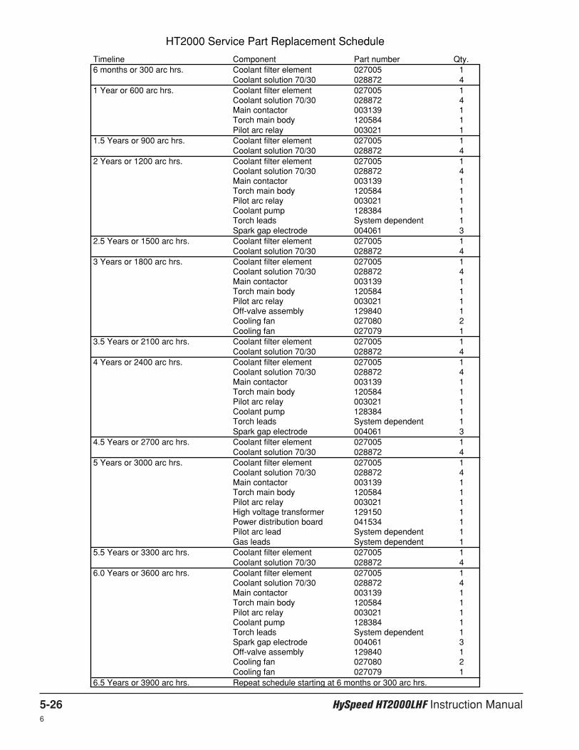
5-26 HySpeed HT2000LHF Instruction Manual6
Timeline Component Part number Qty.6 months or 300 arc hrs. Coolant filter element 027005 1
Coolant solution 70/30 028872 41 Year or 600 arc hrs. Coolant filter element 027005 1
Coolant solution 70/30 028872 4Main contactor 003139 1Torch main body 120584 1Pilot arc relay 003021 1
1.5 Years or 900 arc hrs. Coolant filter element 027005 1Coolant solution 70/30 028872 4
2 Years or 1200 arc hrs. Coolant filter element 027005 1Coolant solution 70/30 028872 4Main contactor 003139 1Torch main body 120584 1Pilot arc relay 003021 1Coolant pump 128384 1Torch leads System dependent 1Spark gap electrode 004061 3
2.5 Years or 1500 arc hrs. Coolant filter element 027005 1Coolant solution 70/30 028872 4
3 Years or 1800 arc hrs. Coolant filter element 027005 1Coolant solution 70/30 028872 4Main contactor 003139 1Torch main body 120584 1Pilot arc relay 003021 1Off-valve assembly 129840 1Cooling fan 027080 2Cooling fan 027079 1
3.5 Years or 2100 arc hrs. Coolant filter element 027005 1Coolant solution 70/30 028872 4
4 Years or 2400 arc hrs. Coolant filter element 027005 1Coolant solution 70/30 028872 4Main contactor 003139 1Torch main body 120584 1Pilot arc relay 003021 1Coolant pump 128384 1Torch leads System dependent 1Spark gap electrode 004061 3
4.5 Years or 2700 arc hrs. Coolant filter element 027005 1Coolant solution 70/30 028872 4
5 Years or 3000 arc hrs. Coolant filter element 027005 1Coolant solution 70/30 028872 4Main contactor 003139 1Torch main body 120584 1Pilot arc relay 003021 1High voltage transformer 129150 1Power distribution board 041534 1Pilot arc lead System dependent 1Gas leads System dependent 1
5.5 Years or 3300 arc hrs. Coolant filter element 027005 1Coolant solution 70/30 028872 4
6.0 Years or 3600 arc hrs. Coolant filter element 027005 1Coolant solution 70/30 028872 4Main contactor 003139 1Torch main body 120584 1Pilot arc relay 003021 1Coolant pump 128384 1Torch leads System dependent 1Spark gap electrode 004061 3Off-valve assembly 129840 1Cooling fan 027080 2Cooling fan 027079 1
6.5 Years or 3900 arc hrs. Repeat schedule starting at 6 months or 300 arc hrs.
HT2000 Service Part Replacement Schedule

HySpeed HT2000LHF Instruction Manual 6-17
Section 6
PARTS LIST
Introduction
See Section 3: Installation and appendices A and C to find part numbers for cables and hoses.
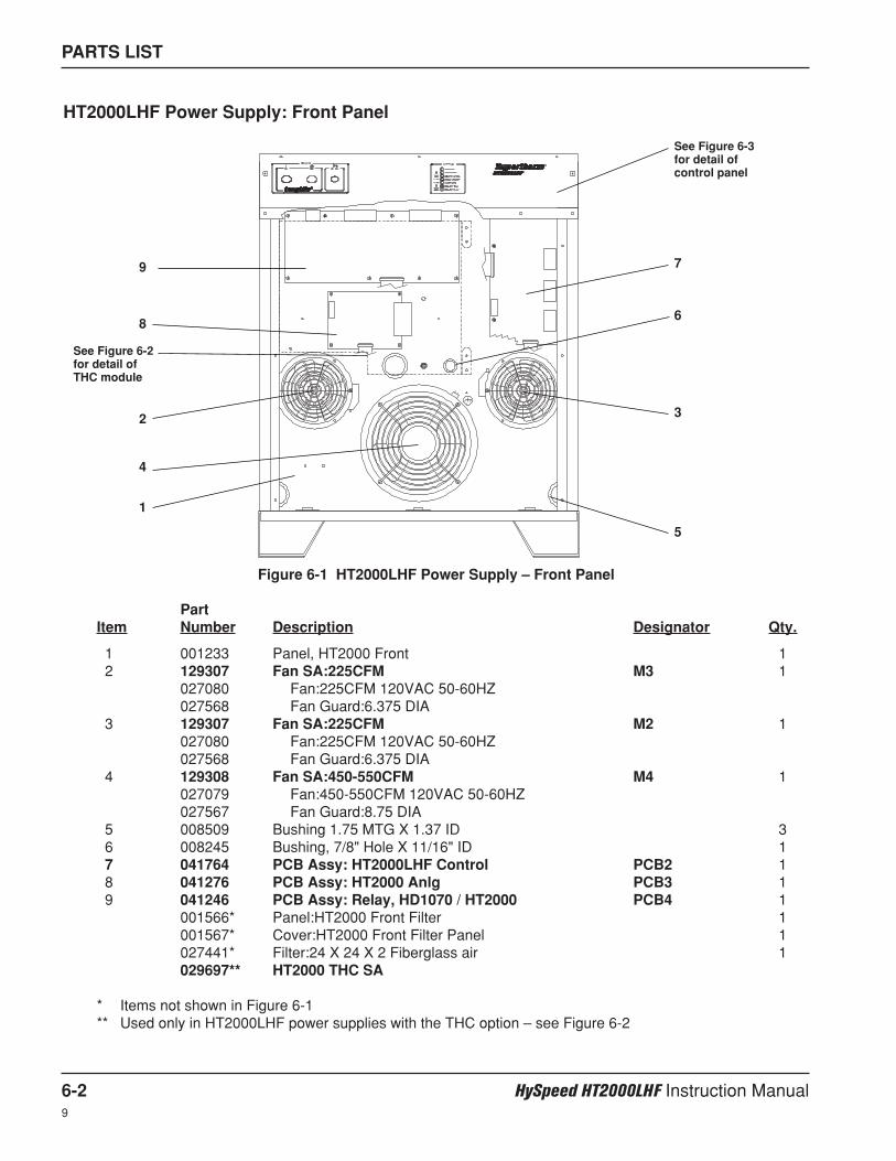
PARTS LIST
6-2 HySpeed HT2000LHF Instruction Manual9
PartItem Number Description Designator Qty.
1 001233 Panel, HT2000 Front 12 129307 Fan SA:225CFM M3 1
027080 Fan:225CFM 120VAC 50-60HZ027568 Fan Guard:6.375 DIA
3 129307 Fan SA:225CFM M2 1027080 Fan:225CFM 120VAC 50-60HZ027568 Fan Guard:6.375 DIA
4 129308 Fan SA:450-550CFM M4 1027079 Fan:450-550CFM 120VAC 50-60HZ027567 Fan Guard:8.75 DIA
5 008509 Bushing 1.75 MTG X 1.37 ID 36 008245 Bushing, 7/8" Hole X 11/16" ID 17 041764 PCB Assy: HT2000LHF Control PCB2 18 041276 PCB Assy: HT2000 Anlg PCB3 19 041246 PCB Assy: Relay, HD1070 / HT2000 PCB4 1
001566* Panel:HT2000 Front Filter 1001567* Cover:HT2000 Front Filter Panel 1027441* Filter:24 X 24 X 2 Fiberglass air 1029697** HT2000 THC SA
* Items not shown in Figure 6-1** Used only in HT2000LHF power supplies with the THC option – see Figure 6-2
Figure 6-1 HT2000LHF Power Supply – Front Panel
HT2000LHF Power Supply: Front Panel
1
2
4
3
5
6
7
8
9
See Figure 6-3for detail ofcontrol panel
See Figure 6-2for detail ofTHC module
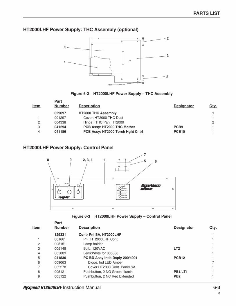
PARTS LIST
HySpeed HT2000LHF Instruction Manual 6-36
PartItem Number Description Designator Qty.
029697 HT2000 THC Assembly 11 001297 Cover: HT2000 THC Dust 12 004338 Hinge: THC Pan, HT2000 23 041294 PCB Assy: HT2000 THC Mother PCB9 14 041186 PCB Assy: HT2000 Torch Hght Cntrl PCB10 1
HT2000LHF Power Supply: THC Assembly (optional)
1
4
2
2
3
Figure 6-2 HT2000LHF Power Supply – THC Assembly
PartItem Number Description Designator Qty.
129331 Contr Pnl SA, HT2000LHF 11 001661 Pnl :HT2000LHF Cont 12 005151 Lamp holder 13 005149 Bulb, 120VAC LT2 14 005089 Lens:White for 005088 15 041536 PC BD Assy Intlk Dsply 200/4001 PCB12 16 009063 Diode, Ind LED Amber 77 002278 Cover:HT2000 Cont. Panel SA 18 005121 Pushbutton, 2 NO Green Illumin PB1/LT1 19 005122 Pushbutton, 2 NC Red Extended PB2 1
Figure 6-3 HT2000LHF Power Supply – Control Panel
HT2000LHF Power Supply: Control Panel
12, 3, 4 5 6
7
8 9
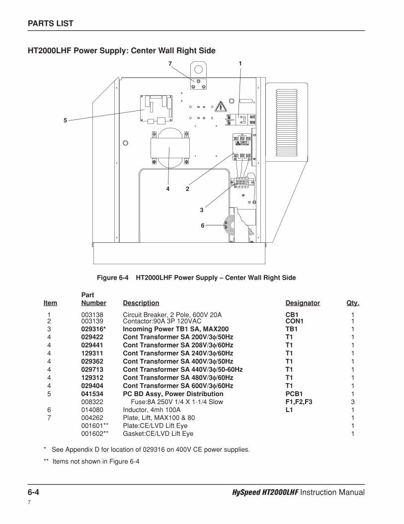
PartItem Number Description Designator Qty.
1 003138 Circuit Breaker, 2 Pole, 600V 20A CB1 12 003139 Contactor:90A 3P 120VAC CON1 13 029316* Incoming Power TB1 SA, MAX200 TB1 14 029422 Cont Transformer SA 200V/3φφ/50Hz T1 14 029441 Cont Transformer SA 208V/3φφ/60Hz T1 14 129311 Cont Transformer SA 240V/3φφ/60Hz T1 14 029362 Cont Transformer SA 400V/3φφ/50Hz T1 14 029713 Cont Transformer SA 440V/3φφ/50-60Hz T1 14 129312 Cont Transformer SA 480V/3φφ/60Hz T1 14 029404 Cont Transformer SA 600V/3φφ/60Hz T1 15 041534 PC BD Assy, Power Distribution PCB1 1
008322 Fuse:8A 250V 1/4 X 1-1/4 Slow F1,F2,F3 36 014080 Inductor, 4mh 100A L1 17 004262 Plate, Lift, MAX100 & 80 1
001601** Plate:CE/LVD Lift Eye 1001602** Gasket:CE/LVD Lift Eye 1
* See Appendix D for location of 029316 on 400V CE power supplies.
** Items not shown in Figure 6-4
PARTS LIST
6-4 HySpeed HT2000LHF Instruction Manual7
HT2000LHF Power Supply: Center Wall Right Side
Figure 6-4 HT2000LHF Power Supply – Center Wall Right Side
1
2
3
4
5
6
7
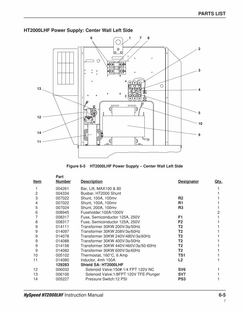
PARTS LIST
HySpeed HT2000LHF Instruction Manual 6-57
Figure 6-5 HT2000LHF Power Supply – Center Wall Left Side
HT2000LHF Power Supply: Center Wall Left Side
1
2
3
4
5
6 7 8
9
10
11
12
13
14
PartItem Number Description Designator Qty.
1 004261 Bar, Lift, MAX100 & 80 12 004334 Busbar, HT2000 Shunt 13 007022 Shunt, 100A, 100mv R2 14 007022 Shunt, 100A, 100mv R1 15 007024 Shunt, 200A, 100mv R3 16 008945 Fuseholder:100A/1000V 27 008317 Fuse, Semiconductor 125A, 250V F1 18 008317 Fuse, Semiconductor 125A, 250V F2 19 014111 Transformer 30KW 200V/3φ/50Hz T2 19 014097 Transformer 30KW 208V/3φ/60Hz T2 19 014078 Transformer 30KW 240V/480V/3φ/60Hz T2 19 014088 Transformer 30KW 400V/3φ/50Hz T2 19 014158 Transformer 30KW 440V/460V/3φ/50-60Hz T2 19 014082 Transformer 30KW 600V/3φ/60Hz T2 1
10 005102 Thermostat, 160°C, 6 Amp TS1 111 014080 Inductor, 4mh 100A L2 1
129283 Shield SA: HT2000LHF12 006032 Solenoid Valve:150# 1/4 FPT 120V NC SV6 113 006106 Solenoid Valve:1/8FPT 120V TFE-Plunger SV7 114 005227 Pressure Switch:12 PSI PS3 1
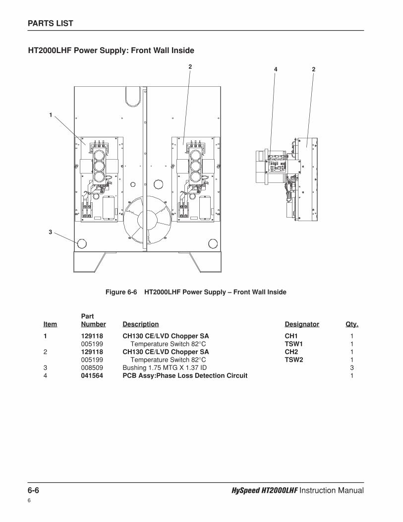
PARTS LIST
6-6 HySpeed HT2000LHF Instruction Manual6
PartItem Number Description Designator Qty.
1 129118 CH130 CE/LVD Chopper SA CH1 1005199 Temperature Switch 82°C TSW1 1
2 129118 CH130 CE/LVD Chopper SA CH2 1005199 Temperature Switch 82°C TSW2 1
3 008509 Bushing 1.75 MTG X 1.37 ID 34 041564 PCB Assy:Phase Loss Detection Circuit 1
HT2000LHF Power Supply: Front Wall Inside
Figure 6-6 HT2000LHF Power Supply – Front Wall Inside
1
3
2 24
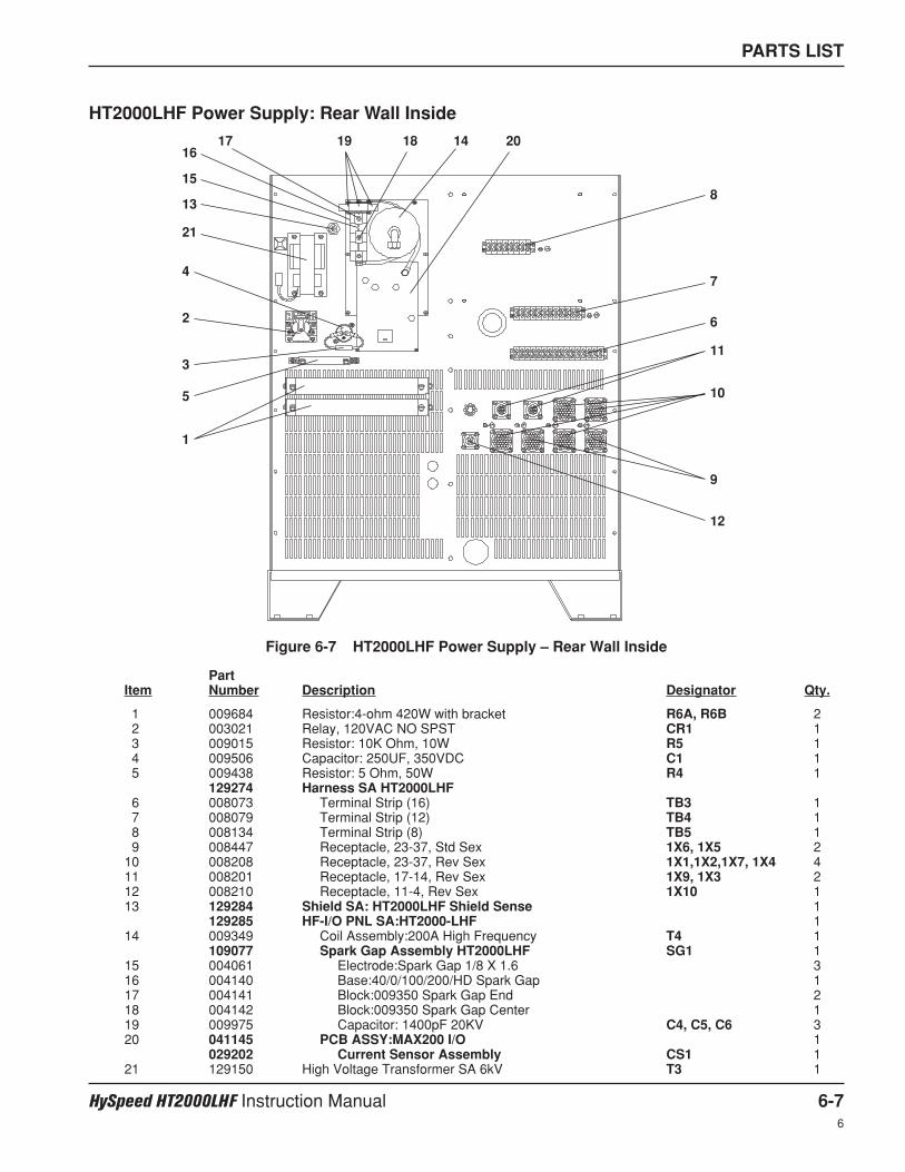
PARTS LIST
HySpeed HT2000LHF Instruction Manual 6-76
Figure 6-7 HT2000LHF Power Supply – Rear Wall Inside
HT2000LHF Power Supply: Rear Wall Inside
1
2
3
4
5
6
7
8
9
10
11
12
13
14
15
1617 1819 20
21
PartItem Number Description Designator Qty.
1 009684 Resistor:4-ohm 420W with bracket R6A, R6B 22 003021 Relay, 120VAC NO SPST CR1 13 009015 Resistor: 10K Ohm, 10W R5 14 009506 Capacitor: 250UF, 350VDC C1 15 009438 Resistor: 5 Ohm, 50W R4 1
129274 Harness SA HT2000LHF6 008073 Terminal Strip (16) TB3 17 008079 Terminal Strip (12) TB4 18 008134 Terminal Strip (8) TB5 19 008447 Receptacle, 23-37, Std Sex 1X6, 1X5 2
10 008208 Receptacle, 23-37, Rev Sex 1X1,1X2,1X7, 1X4 411 008201 Receptacle, 17-14, Rev Sex 1X9, 1X3 212 008210 Receptacle, 11-4, Rev Sex 1X10 113 129284 Shield SA: HT2000LHF Shield Sense 1
129285 HF-I/O PNL SA:HT2000-LHF 114 009349 Coil Assembly:200A High Frequency T4 1
109077 Spark Gap Assembly HT2000LHF SG1 115 004061 Electrode:Spark Gap 1/8 X 1.6 316 004140 Base:40/0/100/200/HD Spark Gap 117 004141 Block:009350 Spark Gap End 218 004142 Block:009350 Spark Gap Center 119 009975 Capacitor: 1400pF 20KV C4, C5, C6 320 041145 PCB ASSY:MAX200 I/O 1
029202 Current Sensor Assembly CS1 121 129150 High Voltage Transformer SA 6kV T3 1
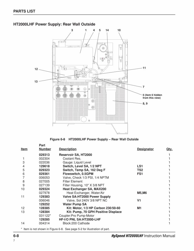
PARTS LIST
6-8 HySpeed HT2000LHF Instruction Manual7
PartItem Number Description Designator Qty.
029313 Reservoir SA, HT2000 11 002304 Coolant Res. 13 022036 Gauge: Liquid Level 14 129618 Switch, Level SA, 1/2 NPT LS1 15 029323 Switch, Temp SA, 162 Deg F TS2 16 029361 Flowswitch, 0.5GPM FS1 17 006053 Valve, Check 1/3 PSI, 1/4 NPTM 18 027005 Filter Element 19 027139 Filter Housing, 10" X 3/8 NPT 1
10 029324 Heat Exchanger SA, MAX200 1027978 Heat Exchanger, Water/Air M5,M6 1
11 129383 Valve SA:HT2000 Power Supply 1006046 Valve, Sol 240V 3/8 NPT NC V1 1129252 Water Pump SA 1
12 128385 Kit: Motor, 1/3 HP Carbon 230/50-60 M1 113 128384 Kit: Pump, 70 GPH Positive Displace 1
031122* Coupler:Pro Pump-Motor 1129285 HF-I/O PNL SA:HT2000-LHF 1
14 004314 Block:200 Cathode 1
* Item is not shown in Figure 6-8. See page 5-2 for illustration of part.
HT2000LHF Power Supply: Rear Wall Outside
Figure 6-8 HT2000LHF Power Supply – Rear Wall Outside
13 4 5
6 (item 6 hiddenfrom this view)
7
8, 9
10
1112
13
14
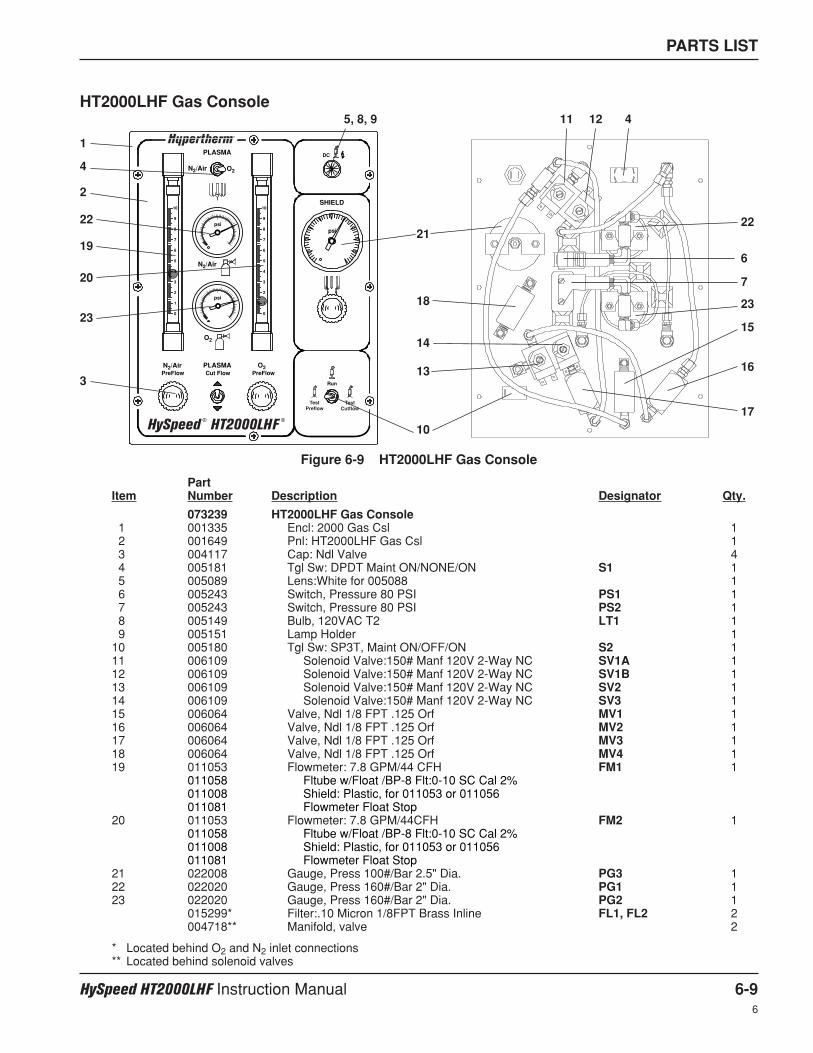
PARTS LIST
HySpeed HT2000LHF Instruction Manual 6-96
PartItem Number Description Designator Qty.
073239 HT2000LHF Gas Console1 001335 Encl: 2000 Gas Csl 12 001649 Pnl: HT2000LHF Gas Csl 13 004117 Cap: Ndl Valve 44 005181 Tgl Sw: DPDT Maint ON/NONE/ON S1 15 005089 Lens:White for 005088 16 005243 Switch, Pressure 80 PSI PS1 17 005243 Switch, Pressure 80 PSI PS2 18 005149 Bulb, 120VAC T2 LT1 19 005151 Lamp Holder 1
10 005180 Tgl Sw: SP3T, Maint ON/OFF/ON S2 111 006109 Solenoid Valve:150# Manf 120V 2-Way NC SV1A 112 006109 Solenoid Valve:150# Manf 120V 2-Way NC SV1B 113 006109 Solenoid Valve:150# Manf 120V 2-Way NC SV2 114 006109 Solenoid Valve:150# Manf 120V 2-Way NC SV3 115 006064 Valve, Ndl 1/8 FPT .125 Orf MV1 116 006064 Valve, Ndl 1/8 FPT .125 Orf MV2 117 006064 Valve, Ndl 1/8 FPT .125 Orf MV3 118 006064 Valve, Ndl 1/8 FPT .125 Orf MV4 119 011053 Flowmeter: 7.8 GPM/44 CFH FM1 1
011058 Fltube w/Float /BP-8 Flt:0-10 SC Cal 2%011008 Shield: Plastic, for 011053 or 011056011081 Flowmeter Float Stop
20 011053 Flowmeter: 7.8 GPM/44CFH FM2 1011058 Fltube w/Float /BP-8 Flt:0-10 SC Cal 2%011008 Shield: Plastic, for 011053 or 011056011081 Flowmeter Float Stop
21 022008 Gauge, Press 100#/Bar 2.5" Dia. PG3 122 022020 Gauge, Press 160#/Bar 2" Dia. PG1 123 022020 Gauge, Press 160#/Bar 2" Dia. PG2 1
015299* Filter:.10 Micron 1/8FPT Brass Inline FL1, FL2 2004718** Manifold, valve 2
* Located behind O2 and N2 inlet connections** Located behind solenoid valves
Figure 6-9 HT2000LHF Gas Console
HT2000LHF Gas Console
PLASMA
N2/Air O2
SHIELD
N2/Air
psi
psipsi
DC
N2/Air
O2
O2PLASMACut Flow PreFlowPreFlow
Run
10
9
8
7
6
5
4
3
2
1
0
10
9
8
7
6
5
4
3
2
1
0
TestPreflow
TestCutflow
HySpeed ® HT2000LHF
®
1
2
3
45, 8, 9
6
7
10
11 12
13
1415
16
17
18
19
20
2122
23
4
22
23
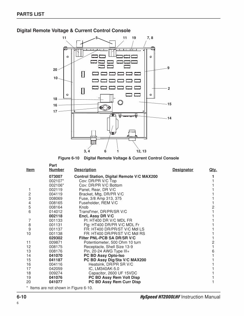
PARTS LIST
6-10 HySpeed HT2000LHF Instruction Manual6
PartItem Number Description Designator Qty.
073007 Control Station, Digital Remote V/C MAX200 1002107* Cov: DR/PR V/C Top 1002106* Cov: DR/PR V/C Bottom 1
1 002119 Panel, Rear, DR V/C 12 004119 Bracket, Mtg, DR/PR V/C 13 008069 Fuse, 3/8 Amp 313, 375 14 008165 Fuseholder, REM V/C 15 008164 Knob 26 014012 Transf'mer, DR/PR/SR V/C 1
002118 Encl, Assy DR V/C 17 001133 Pl: HT400 DR V/C MDL FR 18 001131 Flg: HT400 DR/PR V/C MDL Fr 19 001137 FR: HT400 DR/PR/ST V/C Mdl LS 1
10 001138 FR: HT400 DR/PR/ST V/C Mdl RS 1029302 Filter PNL-PCB SA DR/SR V/C 1
11 009871 Potentiometer, 500 Ohm 10 turn 212 008175 Receptacle, Shell Size 13-9 113 008176 Pin, 20-24 AWG Type III+ 614 041070 PC BD Assy Opto-Iso 115 041187 PC BD Assy Dig/Sta V/C MAX200 116 004116 Heatsink, DR/PR SR V/C 117 042059 IC, LM340AK-5.0 118 009274 Capacitor, 2600 UF 15VDC 119 041076 PC BD Assy Rem Volt Disp 120 041077 PC BD Assy Rem Curr Disp 1
* Items are not shown in Figure 6-10.
Digital Remote Voltage & Current Control Console
1
2
3, 4
5
6
7, 8
9
10
11 11
12, 13
14
1516
17
18
19
20
Figure 6-10 Digital Remote Voltage & Current Control Console
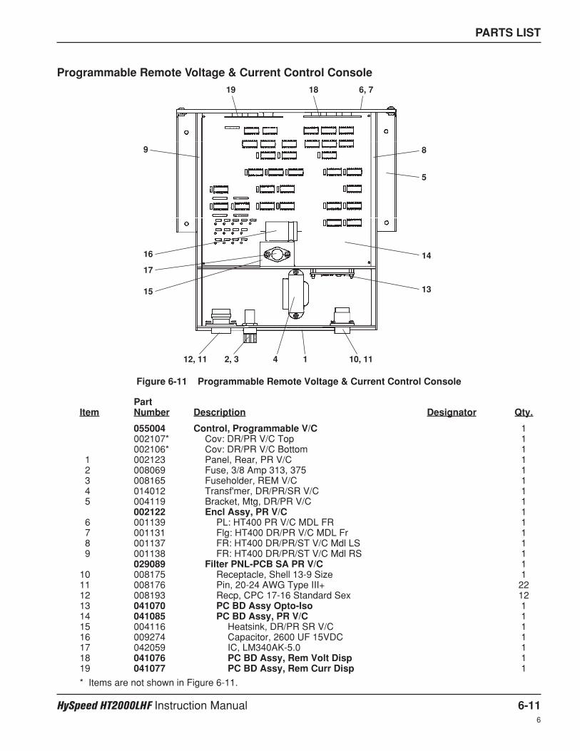
PARTS LIST
HySpeed HT2000LHF Instruction Manual 6-116
Programmable Remote Voltage & Current Control Console
Figure 6-11 Programmable Remote Voltage & Current Control Console
12, 3 4 10, 11
5
6, 7
89
12, 11
13
14
15
16
17
1819
PartItem Number Description Designator Qty.
055004 Control, Programmable V/C 1002107* Cov: DR/PR V/C Top 1002106* Cov: DR/PR V/C Bottom 1
1 002123 Panel, Rear, PR V/C 12 008069 Fuse, 3/8 Amp 313, 375 13 008165 Fuseholder, REM V/C 14 014012 Transf'mer, DR/PR/SR V/C 15 004119 Bracket, Mtg, DR/PR V/C 1
002122 Encl Assy, PR V/C 16 001139 PL: HT400 PR V/C MDL FR 17 001131 Flg: HT400 DR/PR V/C MDL Fr 18 001137 FR: HT400 DR/PR/ST V/C Mdl LS 19 001138 FR: HT400 DR/PR/ST V/C Mdl RS 1
029089 Filter PNL-PCB SA PR V/C 110 008175 Receptacle, Shell 13-9 Size 111 008176 Pin, 20-24 AWG Type III+ 2212 008193 Recp, CPC 17-16 Standard Sex 1213 041070 PC BD Assy Opto-Iso 114 041085 PC BD Assy, PR V/C 115 004116 Heatsink, DR/PR SR V/C 116 009274 Capacitor, 2600 UF 15VDC 117 042059 IC, LM340AK-5.0 118 041076 PC BD Assy, Rem Volt Disp 119 041077 PC BD Assy, Rem Curr Disp 1
* Items are not shown in Figure 6-11.
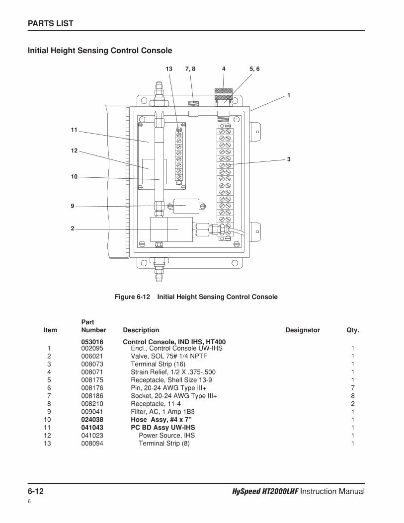
PARTS LIST
6-12 HySpeed HT2000LHF Instruction Manual6
PartItem Number Description Designator Qty.
053016 Control Console, IND IHS, HT400 1 002095 Encl., Control Console UW-IHS 12 006021 Valve, SOL 75# 1/4 NPTF 13 008073 Terminal Strip (16) 14 008071 Strain Relief, 1/2 X .375-.500 15 008175 Receptacle, Shell Size 13-9 16 008176 Pin, 20-24 AWG Type III+ 77 008186 Socket, 20-24 AWG Type III+ 88 008210 Receptacle, 11-4 29 009041 Filter, AC, 1 Amp 1B3 1
10 024038 Hose Assy, #4 x 7" 111 041043 PC BD Assy UW-IHS 112 041023 Power Source, IHS 113 008094 Terminal Strip (8) 1
Initial Height Sensing Control Console
Figure 6-12 Initial Height Sensing Control Console
1
2
3
4 5, 67, 8
9
10
11
12
13
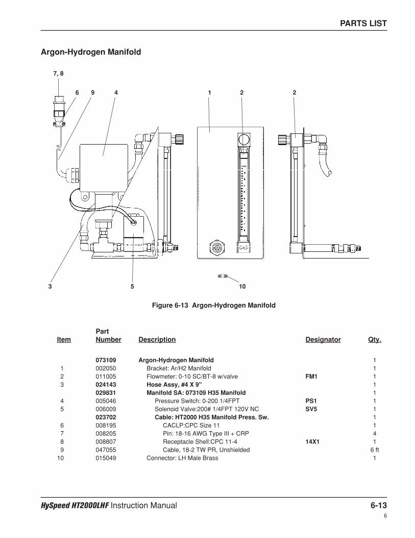
PARTS LIST
HySpeed HT2000LHF Instruction Manual 6-136
Argon-Hydrogen Manifold
Figure 6-13 Argon-Hydrogen Manifold
1 2 2
3
4
5
6
7, 8
9
10
PartItem Number Description Designator Qty.
073109 Argon-Hydrogen Manifold 11 002050 Bracket: Ar/H2 Manifold 12 011005 Flowmeter: 0-10 SC/BT-8 w/valve FM1 13 024143 Hose Assy, #4 X 9" 1
029831 Manifold SA: 073109 H35 Manifold 14 005046 Pressure Switch: 0-200 1/4FPT PS1 15 006009 Solenoid Valve:200# 1/4FPT 120V NC SV5 1
023702 Cable: HT2000 H35 Manifold Press. Sw. 16 008195 CACLP:CPC Size 11 17 008205 Pin: 18-16 AWG Type III + CRP 48 008807 Receptacle Shell:CPC 11-4 14X1 19 047055 Cable, 18-2 TW PR, Unshielded 6 ft
10 015049 Connector: LH Male Brass 1
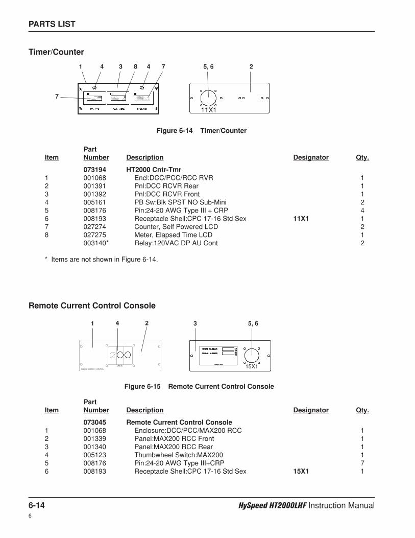
PARTS LIST
6-14 HySpeed HT2000LHF Instruction Manual6
PartItem Number Description Designator Qty.
073194 HT2000 Cntr-Tmr1 001068 Encl:DCC/PCC/RCC RVR 12 001391 Pnl:DCC RCVR Rear 13 001392 Pnl:DCC RCVR Front 14 005161 PB Sw:Blk SPST NO Sub-Mini 25 008176 Pin:24-20 AWG Type III + CRP 46 008193 Receptacle Shell:CPC 17-16 Std Sex 11X1 17 027274 Counter, Self Powered LCD 28 027275 Meter, Elapsed Time LCD 1
003140* Relay:120VAC DP AU Cont 2
* Items are not shown in Figure 6-14.
PartItem Number Description Designator Qty.
073045 Remote Current Control Console1 001068 Enclosure:DCC/PCC/MAX200 RCC 12 001339 Panel:MAX200 RCC Front 13 001340 Panel:MAX200 RCC Rear 14 005123 Thumbwheel Switch:MAX200 15 008176 Pin:24-20 AWG Type III+CRP 76 008193 Receptacle Shell:CPC 17-16 Std Sex 15X1 1
Timer/Counter
11X1
1 4 3 4
7
8 7 5, 6 2
Figure 6-14 Timer/Counter
Remote Current Control Console
Figure 6-15 Remote Current Control Console
1 2 34
15X1
5, 6
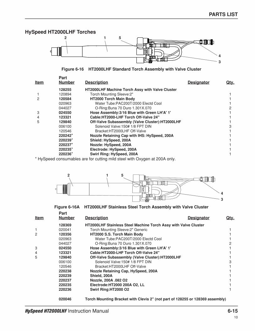
PARTS LIST
HySpeed HT2000LHF Instruction Manual 6-1510
HySpeed HT2000LHF Torches
Figure 6-16 HT2000LHF Standard Torch Assembly with Valve Cluster
12 5
4
3
Figure 6-16A HT2000LHF Stainless Steel Torch Assembly with Valve Cluster
12 5
4
3
PartItem Number Description Designator Qty.
128255 HT2000LHF Machine Torch Assy with Valve Cluster1 120894 Torch Mounting Sleeve:2" 12 120584 HT2000 Torch Main Body 1
020963 Water Tube:PAC200T/2000 Electd Cool 1044027 O-Ring:Buna 70 Duro 1.301X.070 2
3 024550 Hose Assembly:3/16 Blue with Green LH'A' 1' 14 123321 Cable:HT2000-LHF Torch Off-Valve 24" 15 129840 Off-Valve Subassembly (Valve Cluster):HT2000LHF 1
006100 Solenoid Valve:150# 1/8 FPT DIN 3120546 Bracket:HT2000LHF Off-Valve 1220242* Nozzle Retaining Cap with IHS: HySpeed, 200A 1220239* Shield: HySpeed, 200A 1220237* Nozzle: HySpeed, 200A 1220235* Electrode: HySpeed, 200A 1220236* Swirl Ring: HySpeed, 200A 1
* HySpeed consumables are for cutting mild steel with Oxygen at 200A only.
PartItem Number Description Designator Qty.
128369 HT2000LHF Stainless Steel Machine Torch Assy with Valve Cluster1 020041 Torch Mounting Sleeve:2" Generic 12 120356 HT2000 S.S. Torch Main Body 1
020963 Water Tube:PAC200T/2000 Electd Cool 1044027 O-Ring:Buna 70 Duro 1.301X.070 2
3 024550 Hose Assembly:3/16 Blue with Green LH'A' 1' 14 123321 Cable:HT2000-LHF Torch Off-Valve 24" 15 129840 Off-Valve Subassembly (Valve Cluster):HT2000LHF 1
006100 Solenoid Valve:150# 1/8 FPT DIN 3120546 Bracket:HT2000LHF Off-Valve 1220238 Nozzle Retaining Cap, HySpeed, 200A 1220239 Shield, 200A 1220237 Nozzle, 200A .082 O2 1220235 Electrode:HT2000 200A O2, LL 1220236 Swirl Ring:HT2000 O2 1
020046 Torch Mounting Bracket with Clevis 2" (not part of 128255 or 128369 assembly)
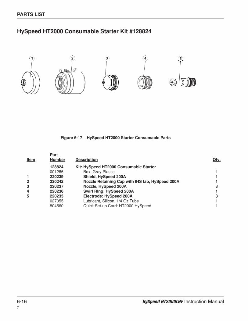
PARTS LIST
6-16 HySpeed HT2000LHF Instruction Manual7
HySpeed HT2000 Consumable Starter Kit #128824
PartItem Number Description Qty.
128824 Kit: HySpeed HT2000 Consumable Starter001285 Box: Gray Plastic 1
1 220239 Shield, HySpeed 200A 12 220242 Nozzle Retaining Cap with IHS tab, HySpeed 200A 13 220237 Nozzle, HySpeed 200A 34 220236 Swirl RIng: HySpeed 200A 15 220235 Electrode: HySpeed 200A 3
027055 Lubricant, Silicon, 1/4 Oz Tube 1804560 Quick Set-up Card: HT2000 HySpeed 1
1 2 53 4
Figure 6-17 HySpeed HT2000 Starter Consumable Parts
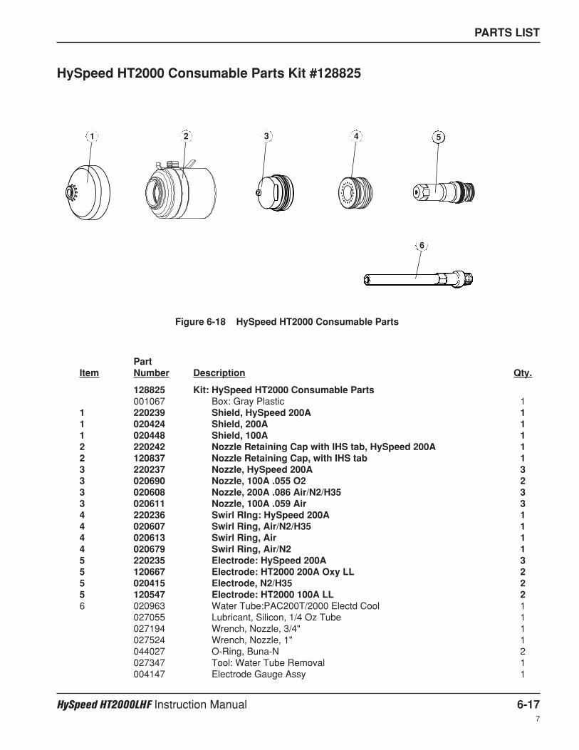
PARTS LIST
HySpeed HT2000LHF Instruction Manual 6-177
HySpeed HT2000 Consumable Parts Kit #128825
PartItem Number Description Qty.
128825 Kit: HySpeed HT2000 Consumable Parts001067 Box: Gray Plastic 1
1 220239 Shield, HySpeed 200A 11 020424 Shield, 200A 11 020448 Shield, 100A 12 220242 Nozzle Retaining Cap with IHS tab, HySpeed 200A 12 120837 Nozzle Retaining Cap, with IHS tab 13 220237 Nozzle, HySpeed 200A 33 020690 Nozzle, 100A .055 O2 23 020608 Nozzle, 200A .086 Air/N2/H35 33 020611 Nozzle, 100A .059 Air 34 220236 Swirl RIng: HySpeed 200A 14 020607 Swirl Ring, Air/N2/H35 14 020613 Swirl Ring, Air 14 020679 Swirl Ring, Air/N2 15 220235 Electrode: HySpeed 200A 35 120667 Electrode: HT2000 200A Oxy LL 25 020415 Electrode, N2/H35 25 120547 Electrode: HT2000 100A LL 26 020963 Water Tube:PAC200T/2000 Electd Cool 1
027055 Lubricant, Silicon, 1/4 Oz Tube 1027194 Wrench, Nozzle, 3/4" 1027524 Wrench, Nozzle, 1" 1044027 O-Ring, Buna-N 2027347 Tool: Water Tube Removal 1004147 Electrode Gauge Assy 1
1 2 53 4
6
Figure 6-18 HySpeed HT2000 Consumable Parts

PARTS LIST
6-18 HySpeed HT2000LHF Instruction Manual7
PartItem Number Description Qty.
028602 Kit: HT2000 Consumable Parts001067 Box: Gray Plastic 1
1 020424 Shield, 200A 11 020448 Shield, 100A 12 120837 Nozzle Retaining Cap, with IHS tab 13 020605 Nozzle, 200A .082 O2 53 020690 Nozzle, 100A .055 O2 34 020608 Nozzle, 200A .086 Air/N2/H35 54 020611 Nozzle, 100A .059 Air 35 120833 Swirl Ring: HT2000 O2 16 020607 Swirl Ring, Air/N2/H35 16 020613 Swirl Ring, Air 16 020679 Swirl Ring, Air/N2 17 120667 Electrode:HT2000 200A O2 LL 57 020415 Electrode, N2/H35 57 120547 Electrode, HT2000 100A LL 38 020963 Water Tube:PAC200T/2000 Electd Cool 1
027055 Lubricant, Silicon, 1/4 Oz Tube 1027194 Wrench, Nozzle, 3/4" 1027524 Wrench, Nozzle, 1" 1044027 O-Ring, Buna-N 2027347 Tool: Water Tube Removal 1004147 Electrode Gauge Assy 1
Figure 6-19 HT2000 Consumable Parts
HT2000 Consumable Parts Kit
1 2
3
4
5
6
7
8
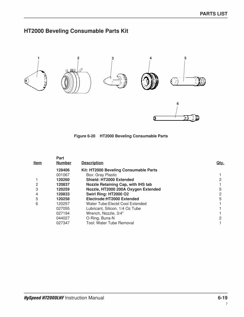
PARTS LIST
HySpeed HT2000LHF Instruction Manual 6-197
HT2000 Beveling Consumable Parts Kit
PartItem Number Description Qty.
128406 Kit: HT2000 Beveling Consumable Parts001067 Box: Gray Plastic 1
1 120260 Shield: HT2000 Extended 22 120837 Nozzle Retaining Cap, with IHS tab 13 120259 Nozzle, HT2000 200A Oxygen Extended 54 120833 Swirl Ring: HT2000 O2 25 120258 Electrode:HT2000 Extended 56 120257 Water Tube:Electd Cool Extended 1
027055 Lubricant, Silicon, 1/4 Oz Tube 1027194 Wrench, Nozzle, 3/4" 1044027 O-Ring, Buna-N 2027347 Tool: Water Tube Removal 1
Figure 6-20 HT2000 Beveling Consumable Parts
1 2 53 4
6
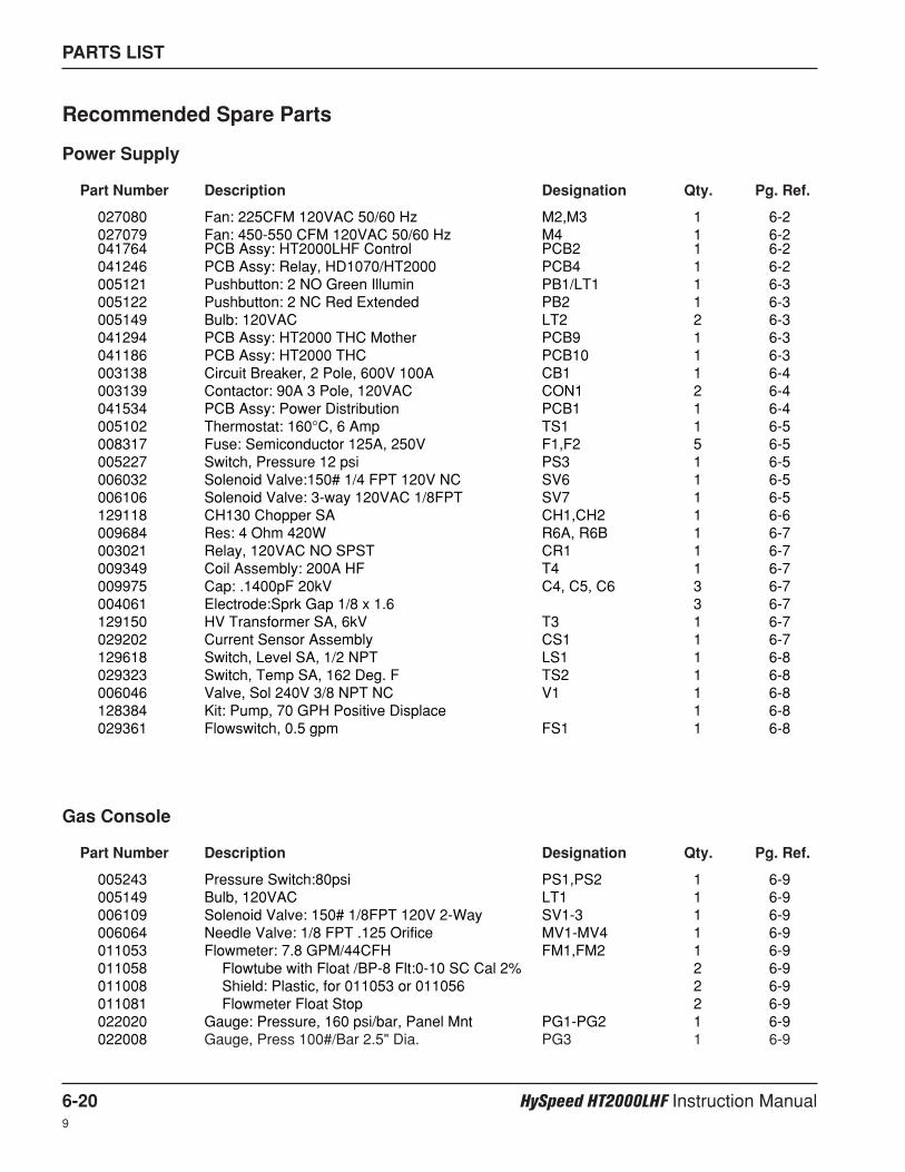
PARTS LIST
6-20 HySpeed HT2000LHF Instruction Manual9
Recommended Spare Parts
Power Supply
Part Number Description Designation Qty. Pg. Ref.
027080 Fan: 225CFM 120VAC 50/60 Hz M2,M3 1 6-2027079 Fan: 450-550 CFM 120VAC 50/60 Hz M4 1 6-2041764 PCB Assy: HT2000LHF Control PCB2 1 6-2041246 PCB Assy: Relay, HD1070/HT2000 PCB4 1 6-2005121 Pushbutton: 2 NO Green Illumin PB1/LT1 1 6-3005122 Pushbutton: 2 NC Red Extended PB2 1 6-3005149 Bulb: 120VAC LT2 2 6-3041294 PCB Assy: HT2000 THC Mother PCB9 1 6-3041186 PCB Assy: HT2000 THC PCB10 1 6-3003138 Circuit Breaker, 2 Pole, 600V 100A CB1 1 6-4003139 Contactor: 90A 3 Pole, 120VAC CON1 2 6-4041534 PCB Assy: Power Distribution PCB1 1 6-4005102 Thermostat: 160°C, 6 Amp TS1 1 6-5008317 Fuse: Semiconductor 125A, 250V F1,F2 5 6-5005227 Switch, Pressure 12 psi PS3 1 6-5006032 Solenoid Valve:150# 1/4 FPT 120V NC SV6 1 6-5006106 Solenoid Valve: 3-way 120VAC 1/8FPT SV7 1 6-5129118 CH130 Chopper SA CH1,CH2 1 6-6009684 Res: 4 Ohm 420W R6A, R6B 1 6-7003021 Relay, 120VAC NO SPST CR1 1 6-7009349 Coil Assembly: 200A HF T4 1 6-7009975 Cap: .1400pF 20kV C4, C5, C6 3 6-7004061 Electrode:Sprk Gap 1/8 x 1.6 3 6-7129150 HV Transformer SA, 6kV T3 1 6-7029202 Current Sensor Assembly CS1 1 6-7129618 Switch, Level SA, 1/2 NPT LS1 1 6-8029323 Switch, Temp SA, 162 Deg. F TS2 1 6-8006046 Valve, Sol 240V 3/8 NPT NC V1 1 6-8128384 Kit: Pump, 70 GPH Positive Displace 1 6-8029361 Flowswitch, 0.5 gpm FS1 1 6-8
Gas Console
Part Number Description Designation Qty. Pg. Ref.
005243 Pressure Switch:80psi PS1,PS2 1 6-9005149 Bulb, 120VAC LT1 1 6-9006109 Solenoid Valve: 150# 1/8FPT 120V 2-Way SV1-3 1 6-9006064 Needle Valve: 1/8 FPT .125 Orifice MV1-MV4 1 6-9011053 Flowmeter: 7.8 GPM/44CFH FM1,FM2 1 6-9011058 Flowtube with Float /BP-8 Flt:0-10 SC Cal 2% 2 6-9011008 Shield: Plastic, for 011053 or 011056 2 6-9011081 Flowmeter Float Stop 2 6-9022020 Gauge: Pressure, 160 psi/bar, Panel Mnt PG1-PG2 1 6-9022008 Gauge, Press 100#/Bar 2.5" Dia. PG3 1 6-9
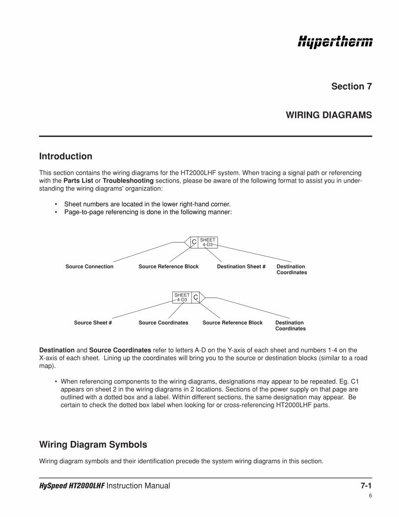
HySpeed HT2000LHF Instruction Manual 7-16
Section 7
WIRING DIAGRAMS
Introduction
This section contains the wiring diagrams for the HT2000LHF system. When tracing a signal path or referencingwith the Parts List or Troubleshooting sections, please be aware of the following format to assist you in under-standing the wiring diagrams' organization:
• Sheet numbers are located in the lower right-hand corner.• Page-to-page referencing is done in the following manner:
C SHEET4-D3
CSHEET4-D3
Destination and Source Coordinates refer to letters A-D on the Y-axis of each sheet and numbers 1-4 on the X-axis of each sheet. Lining up the coordinates will bring you to the source or destination blocks (similar to a roadmap).
• When referencing components to the wiring diagrams, designations may appear to be repeated. Eg. C1appears on sheet 2 in the wiring diagrams in 2 locations. Sections of the power supply on that page areoutlined with a dotted box and a label. Within different sections, the same designation may appear. Becertain to check the dotted box label when looking for or cross-referencing HT2000LHF parts.
Wiring Diagram Symbols
Wiring diagram symbols and their identification precede the system wiring diagrams in this section.
Source Connection Source Reference Block Destination Sheet # DestinationCoordinates
Source Sheet # Source Coordinates Source Reference Block DestinationCoordinates
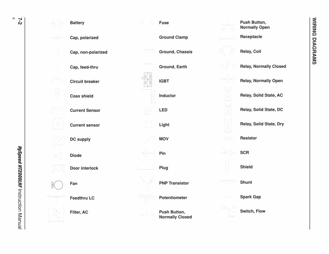
WIR
ING
DIA
GR
AM
S
7-2H
ySpeed H
T20
00
LHF
Instruction Manual
6
Battery
Cap, polarized
Cap, non-polarized
Cap, feed-thru
Circuit breaker
Coax shield
Current Sensor
Current sensor
Diode
Door interlock
Fan
Feedthru LC
Filter, AC
DC supply
Fuse
Ground Clamp
Ground, Chassis
Ground, Earth
IGBT
Inductor
LED
Light
Pin
Plug
PNP Transistor
Potentiometer
Push Button,Normally Closed
MOV
Push Button,Normally Open
Receptacle
Relay, Coil
Relay, Normally Closed
Relay, Normally Open
Relay, Solid State, AC
Relay, Solid State, DC
Relay, Solid State, Dry
SCR
Shield
Shunt
Spark Gap
Switch, Flow
Resistor
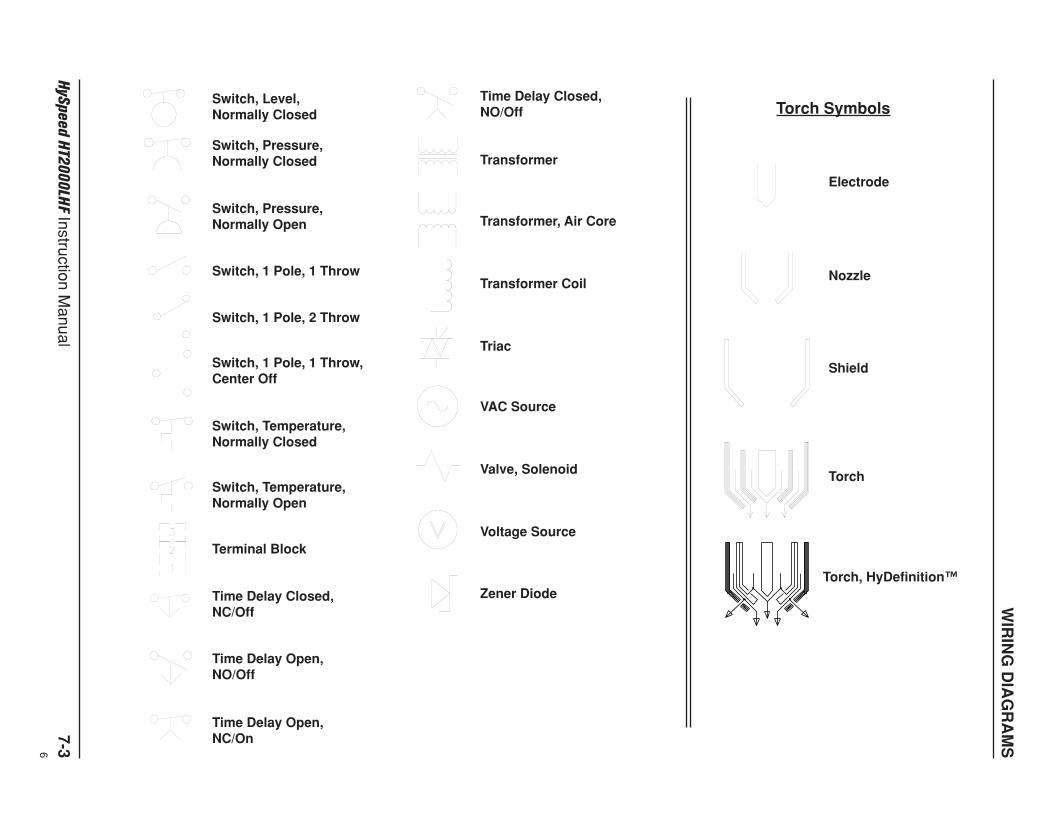
WIR
ING
DIA
GR
AM
S
HyS
peed H
T20
00
LHF
Instruction Manual
7-36
Switch, Level,Normally Closed
Time Delay Closed,NO/Off
Transformer
Electrode
Torch Symbols
Nozzle
Shield
Torch
Transformer, Air Core
Transformer Coil
Valve, Solenoid
Voltage Source
Zener Diode
VAC Source
Triac
Switch, Pressure,Normally Closed
Switch, Pressure,Normally Open
Switch, 1 Pole, 1 Throw
Switch, 1 Pole, 2 Throw
Switch, 1 Pole, 1 Throw,Center Off
Switch, Temperature,Normally Closed
Switch, Temperature,Normally Open
Time Delay Closed,NC/Off
Time Delay Open,NO/Off
Time Delay Open,NC/On
Terminal Block
Torch, HyDefinition™
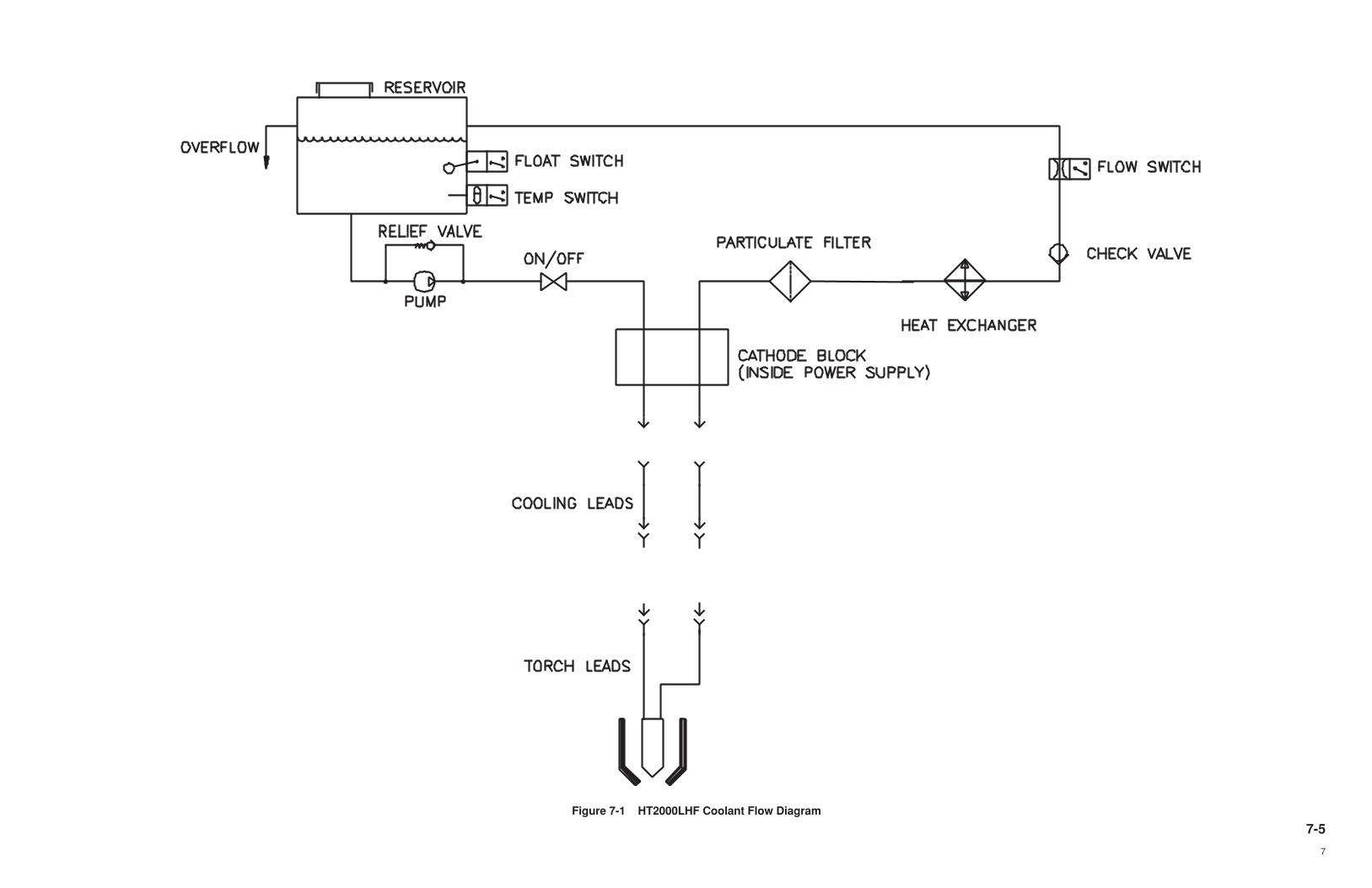
7-5
7
Figure 7-1 HT2000LHF Coolant Flow Diagram
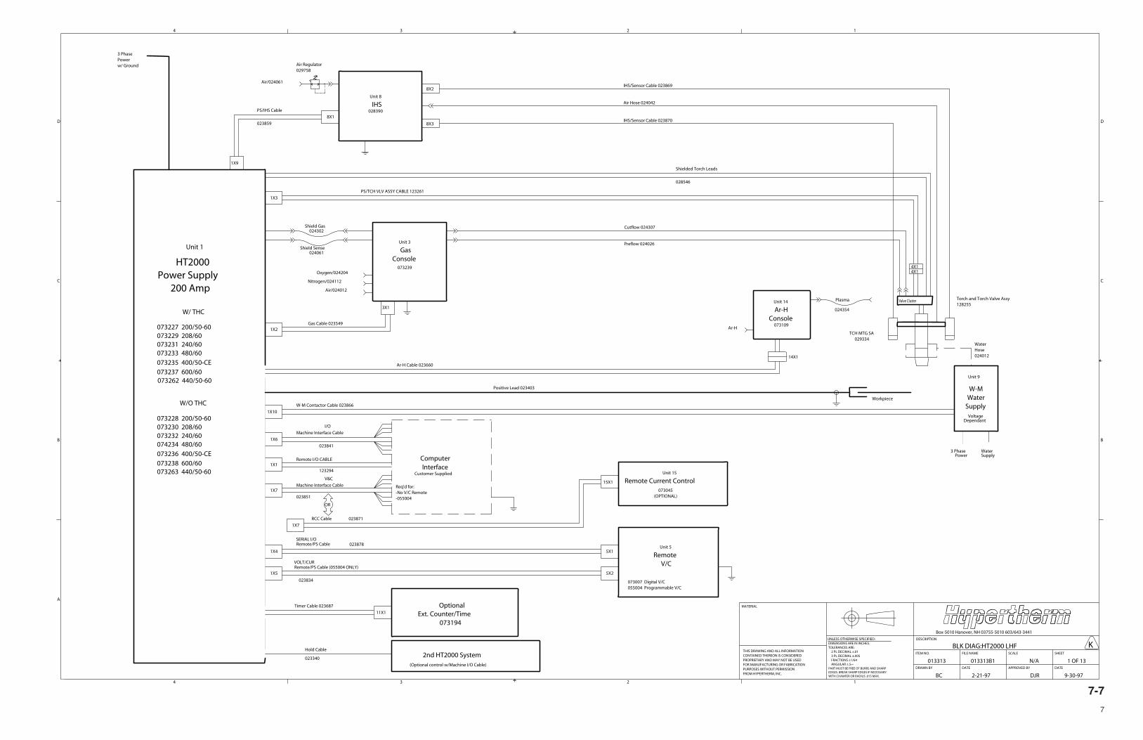
7-7
7
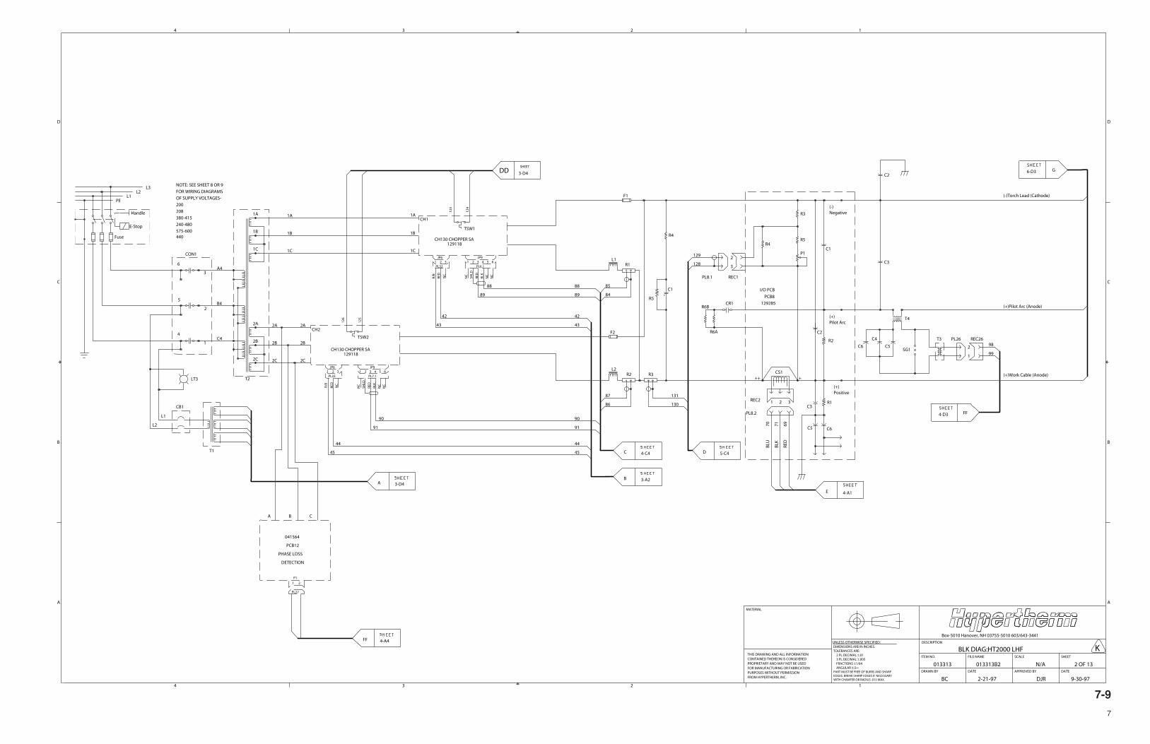
7-9
7
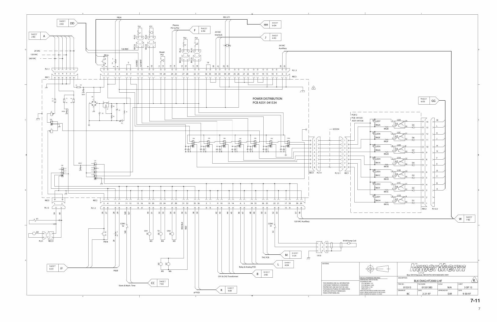
7-11
7

7-13
7
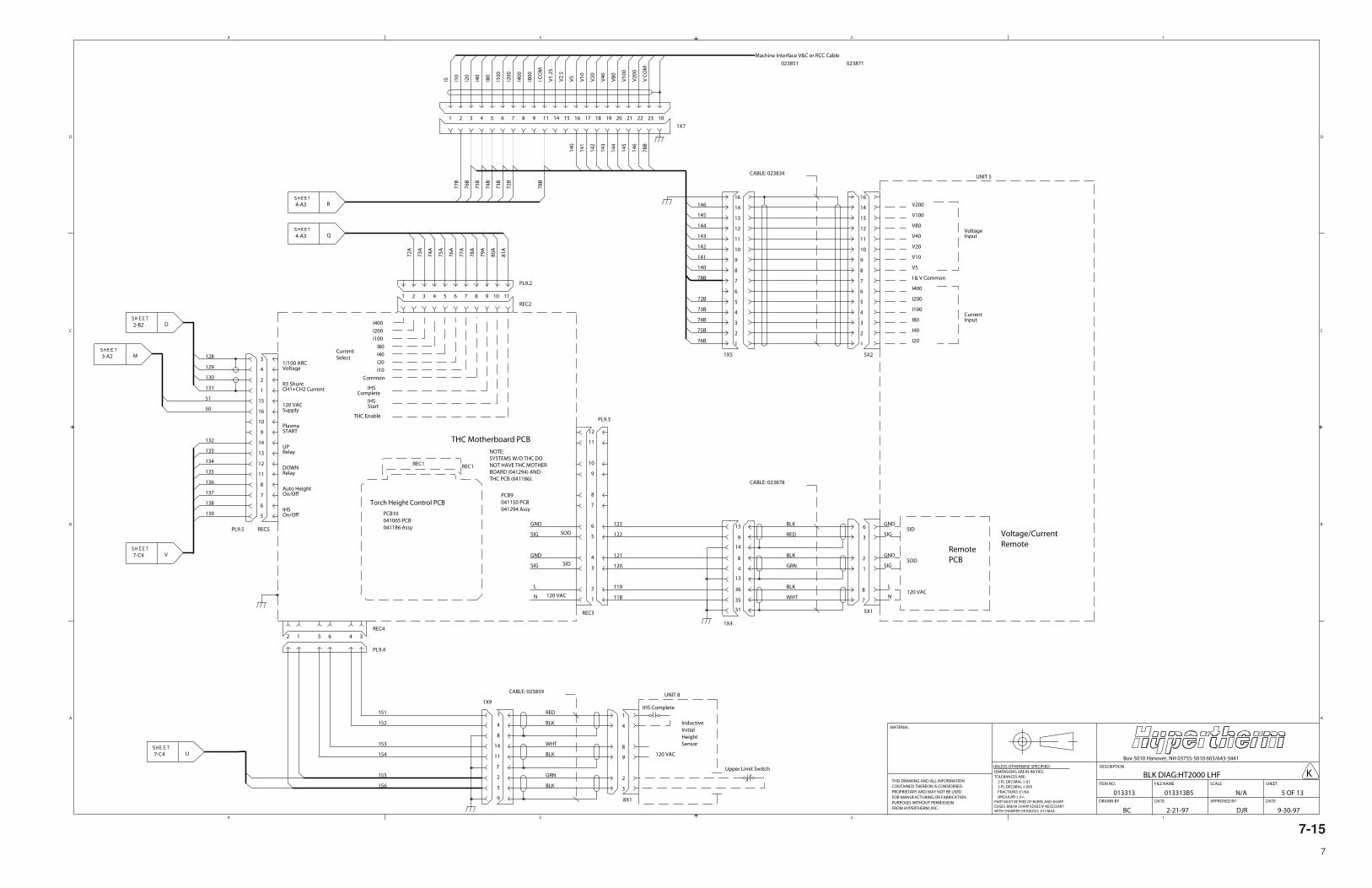
7-15
7
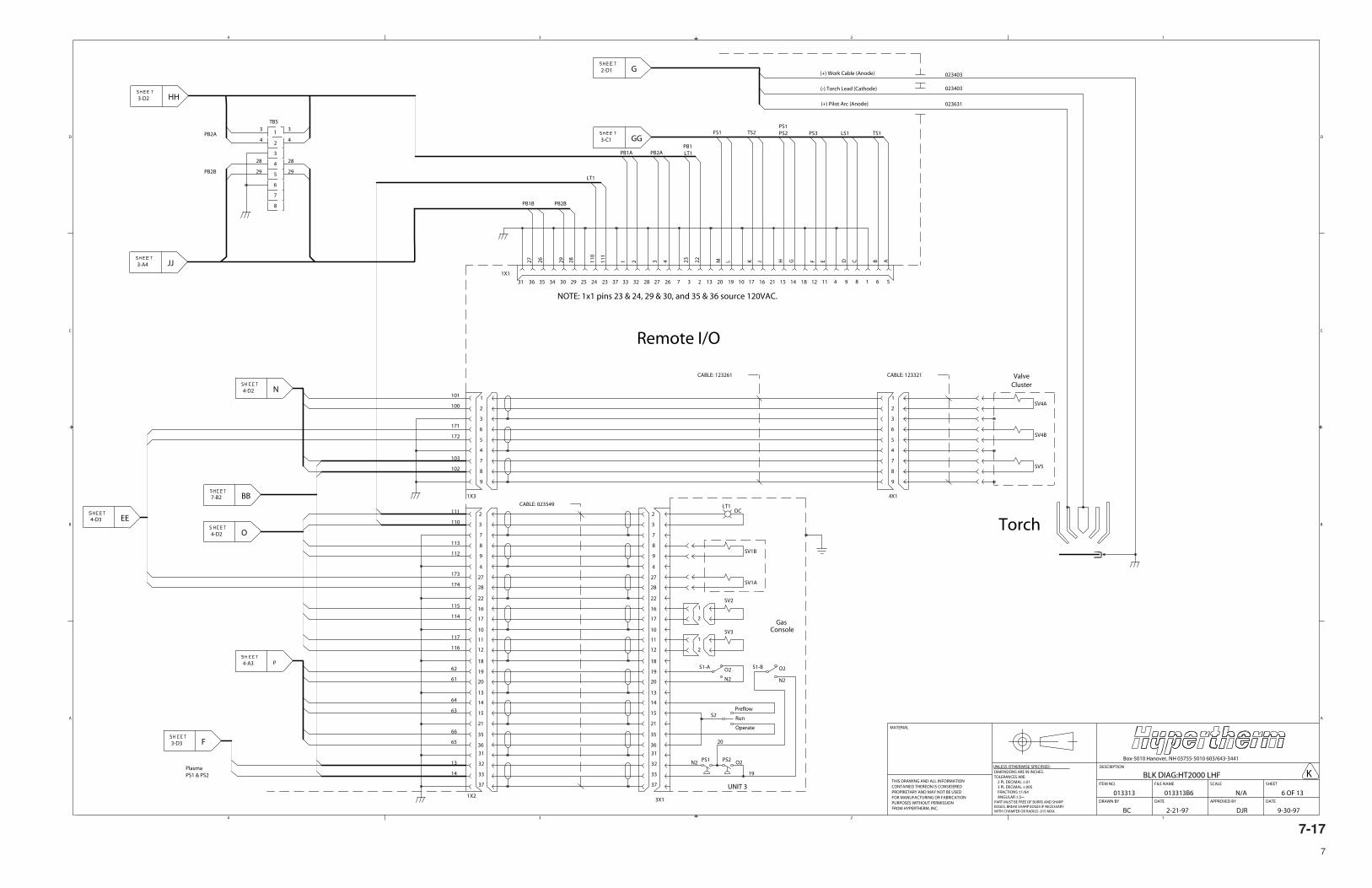
7-17
7
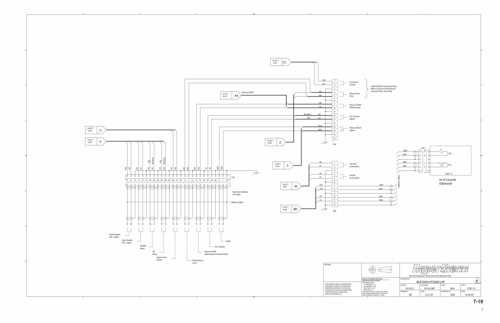
7-19
7
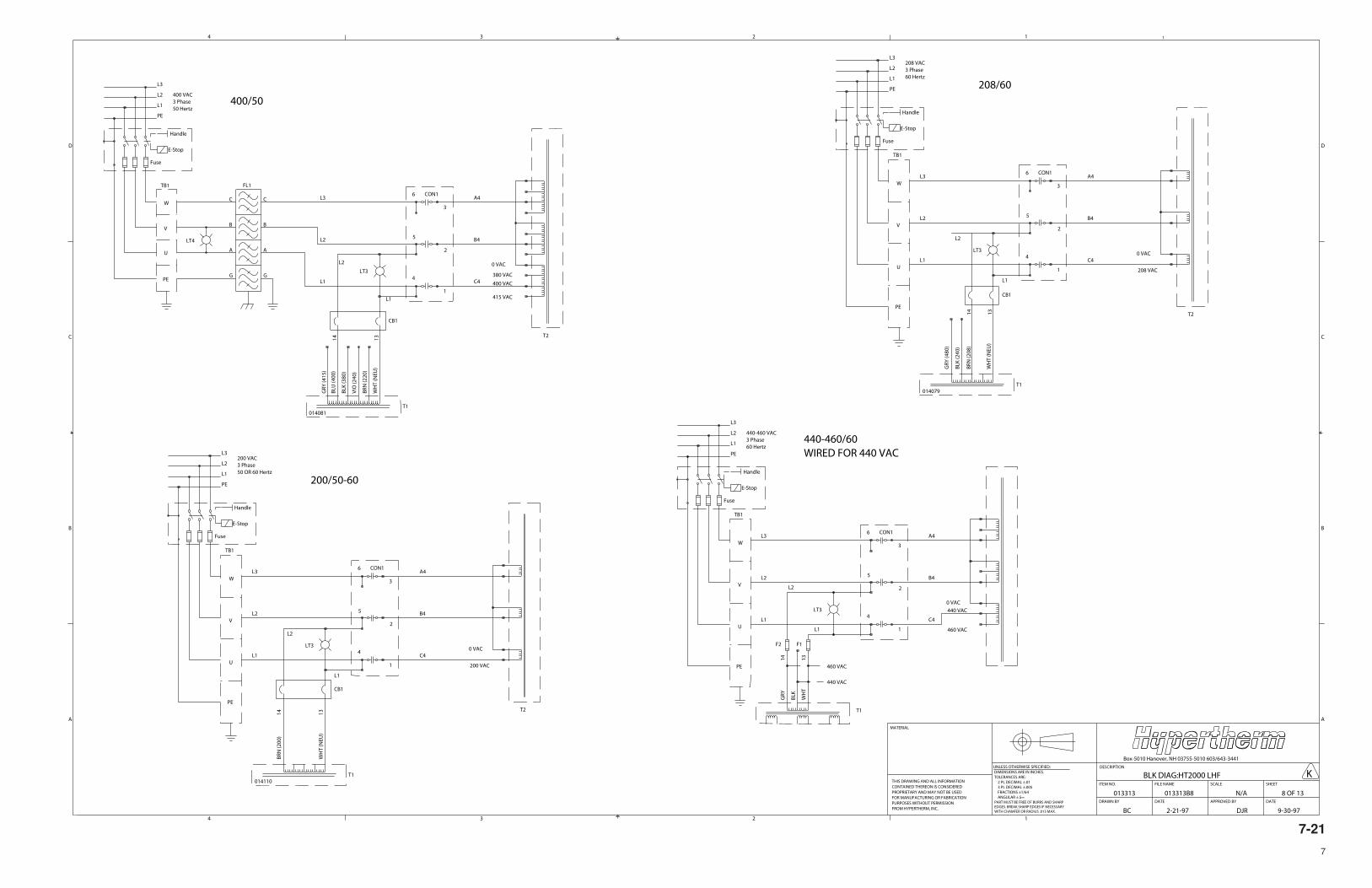
7-21
7
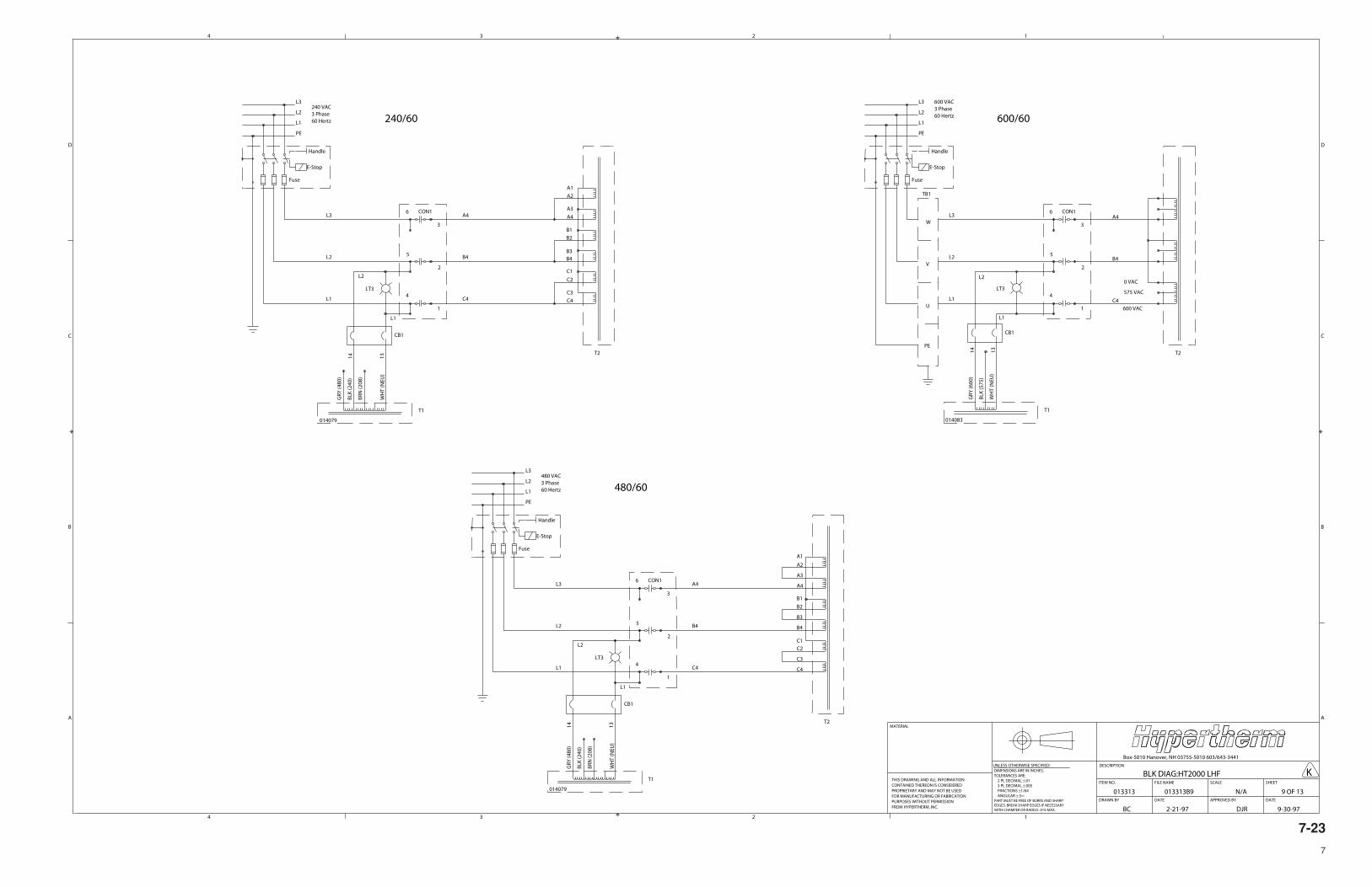
7-23
7
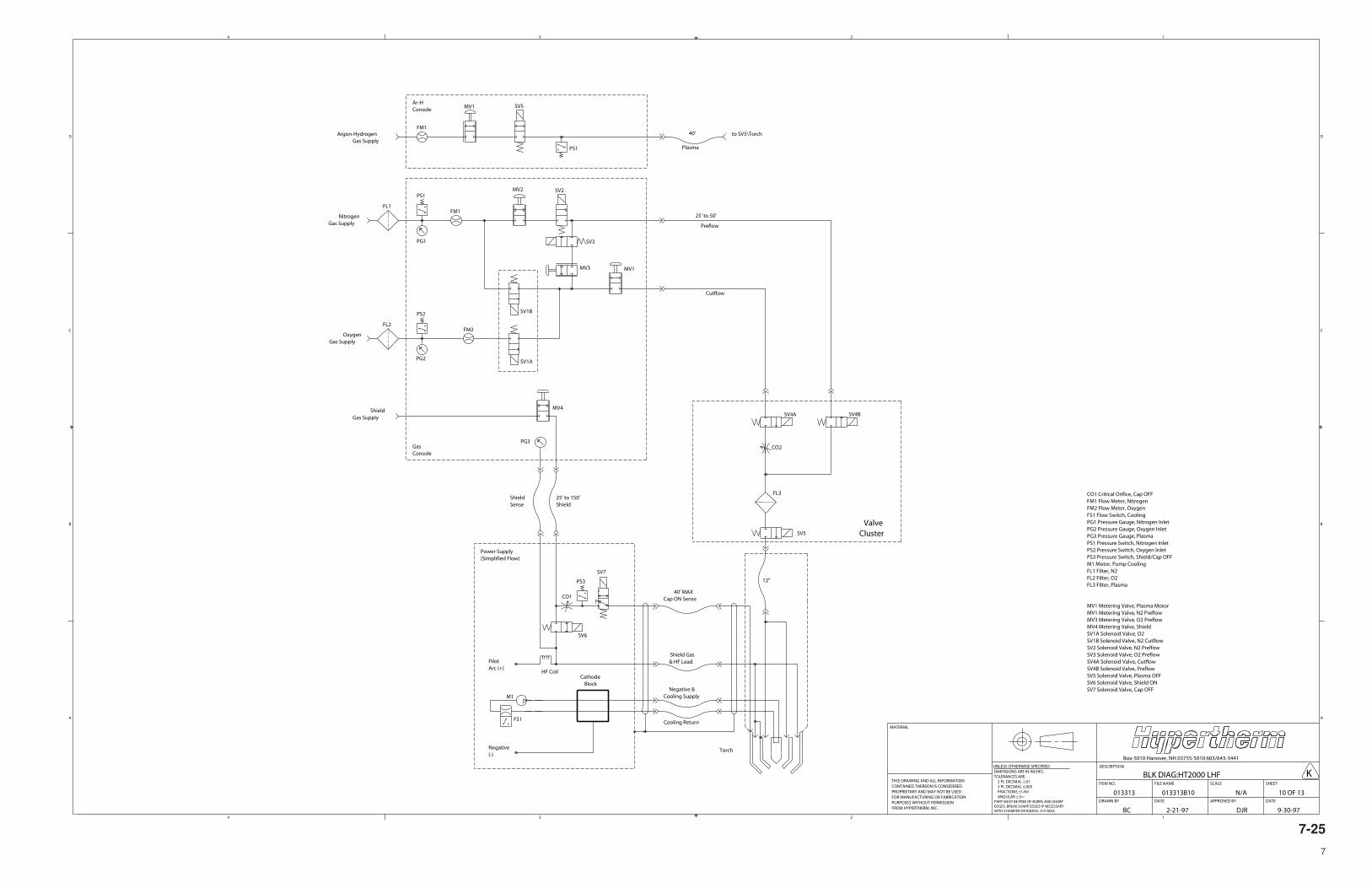
7-25
7
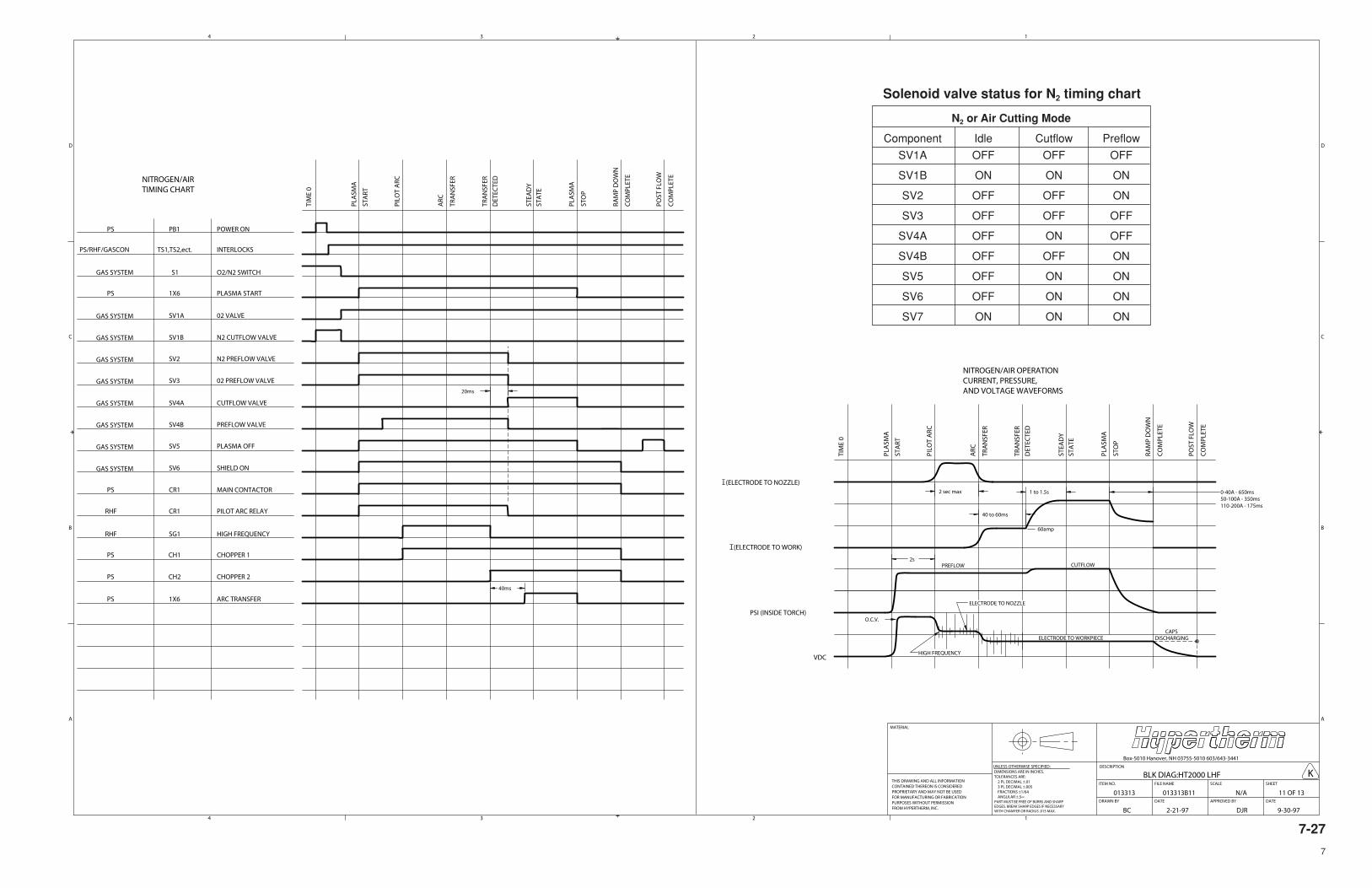
7-27
7
Solenoid valve status for N2 timing chart
N2 or Air Cutting Mode
Component Idle Cutflow Preflow
SV1A OFF OFF OFF
SV1B ON ON ON
SV2 OFF OFF ON
SV3 OFF OFF OFF
SV4A OFF ON OFF
SV4B OFF OFF ON
SV5 OFF ON ON
SV6 OFF ON ON
SV7 ON ON ON
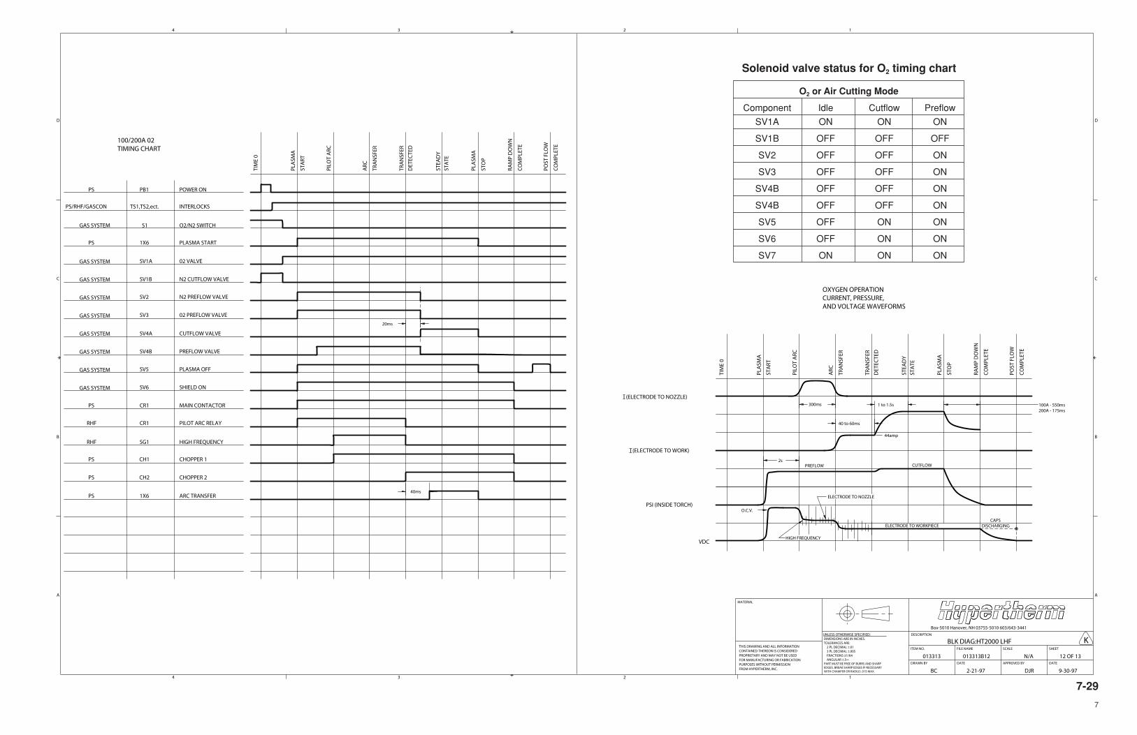
7-29
7
O2 or Air Cutting Mode
Component Idle Cutflow Preflow
SV1A ON ON ON
SV1B OFF OFF OFF
SV2 OFF OFF ON
SV3 OFF OFF ON
SV4B OFF OFF ON
SV4B OFF OFF ON
SV5 OFF ON ON
SV6 OFF ON ON
SV7 ON ON ON
Solenoid valve status for O2 timing chart
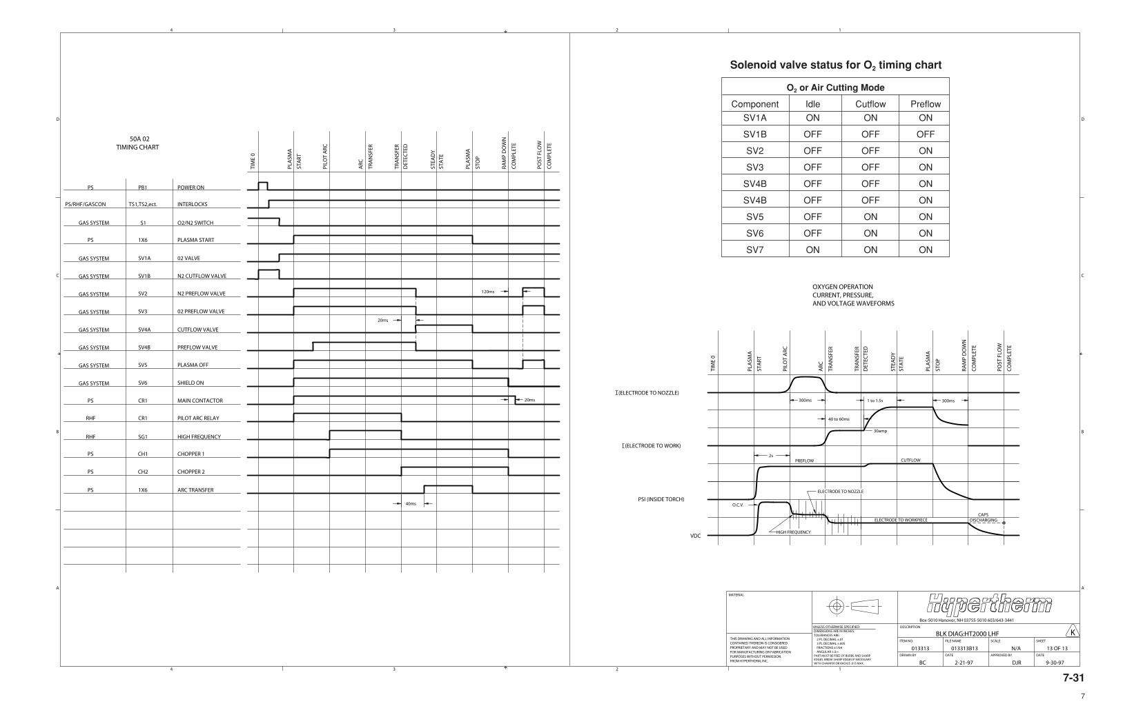
7-31
7
O2 or Air Cutting Mode
Component Idle Cutflow Preflow
SV1A ON ON ON
SV1B OFF OFF OFF
SV2 OFF OFF ON
SV3 OFF OFF ON
SV4B OFF OFF ON
SV4B OFF OFF ON
SV5 OFF ON ON
SV6 OFF ON ON
SV7 ON ON ON
Solenoid valve status for O2 timing chart
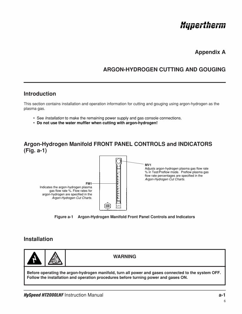
HySpeed HT2000LHF Instruction Manual a-16
Appendix A
ARGON-HYDROGEN CUTTING AND GOUGING
Introduction
This section contains installation and operation information for cutting and gouging using argon-hydrogen as theplasma gas.
• See Installation to make the remaining power supply and gas console connections.• Do not use the water muffler when cutting with argon-hydrogen!
MV1Adjusts argon-hydrogen plasma gas flow rate% in Test/Preflow mode. Preflow plasma gasflow rate percentages are specified in theArgon-Hydrogen Cut Charts.
FM1Indicates the argon-hydrogen plasma
gas flow rate %. Flow rates for argon-hydrogen are specified in the
Argon-Hydrogen Cut Charts.
Figure a-1 Argon-Hydrogen Manifold Front Panel Controls and Indicators
Argon-Hydrogen Manifold FRONT PANEL CONTROLS and INDICATORS (Fig. a-1)
Installation
WARNING
Before operating the argon-hydrogen manifold, turn all power and gases connected to the system OFF.Follow the installation and operation procedures before turning power and gases ON.
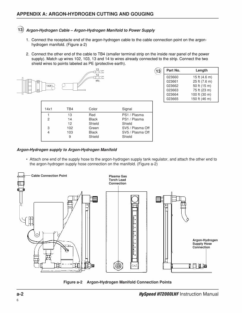
APPENDIX A: ARGON-HYDROGEN CUTTING AND GOUGING
a-2 HySpeed HT2000LHF Instruction Manual6
Argon-Hydrogen supply to Argon-Hydrogen Manifold
• Attach one end of the supply hose to the argon-hydrogen supply tank regulator, and attach the other end tothe argon-hydrogen supply hose connection on the manifold. (Figure a-2)
Figure a-2 Argon-Hydrogen Manifold Connection Points
Cable Connection Point Plasma GasTorch LeadConnection
Argon-HydrogenSupply HoseConnection
Argon-Hydrogen Cable – Argon-Hydrogen Manifold to Power Supply
1. Connect the receptacle end of the argon-hydrogen cable to the cable connection point on the argon-hydrogen manifold. (Figure a-2)
2. Connect the other end of the cable to TB4 (smaller terminal strip on the inside rear panel of the powersupply). Match up wires 102, 103, 13 and 14 to wires already connected to the strip. Connect the twoshield wires to points labeled as PE (protective earth).
Part No. Length
023660 15 ft (4.6 m)023661 25 ft (7.6 m)023662 50 ft (15 m)023663 75 ft (23 m)023664 100 ft (30 m)023665 150 ft (46 m)
13
13
14X1
13
14
etc.
14x1 TB4 Color Signal
1 13 Red PS1 / Plasma2 14 Black PS1 / Plasma
12 Shield Shield3 102 Green SV5 / Plasma Off4 103 Black SV5 / Plasma Off
9 Shield Shield
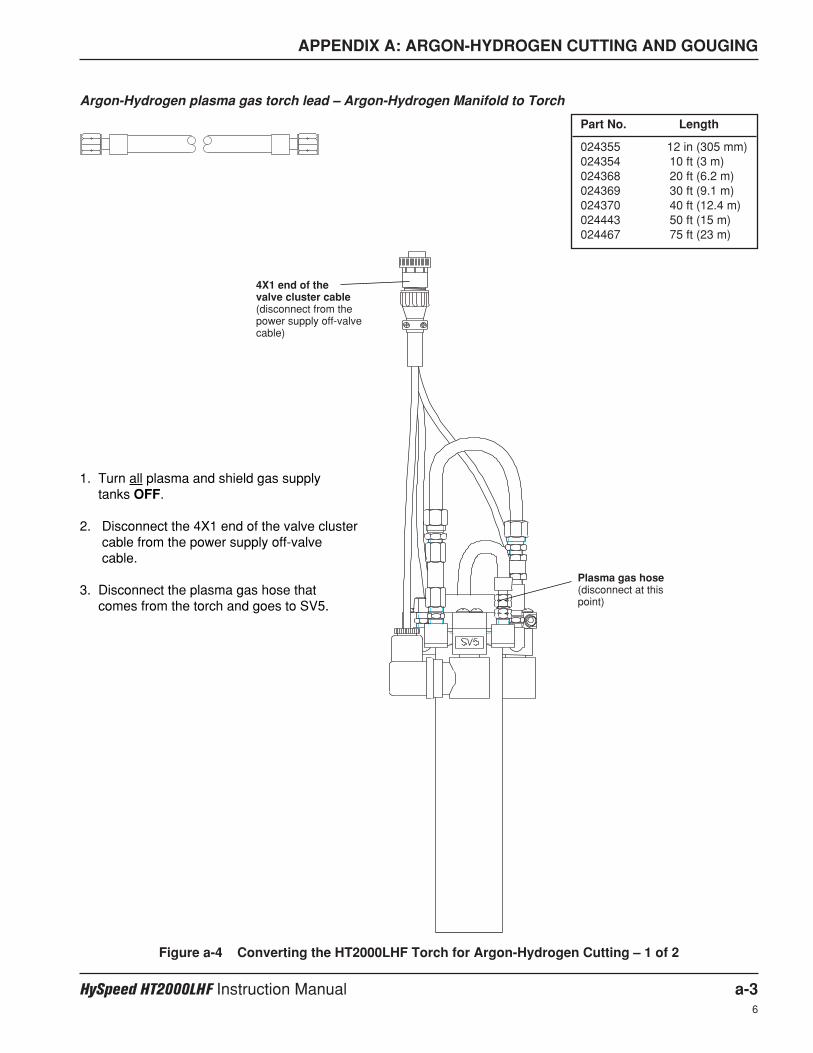
APPENDIX A: ARGON-HYDROGEN CUTTING AND GOUGING
HySpeed HT2000LHF Instruction Manual a-36
Argon-Hydrogen plasma gas torch lead – Argon-Hydrogen Manifold to Torch
Part No. Length
024355 12 in (305 mm)024354 10 ft (3 m)024368 20 ft (6.2 m)024369 30 ft (9.1 m)024370 40 ft (12.4 m)024443 50 ft (15 m)024467 75 ft (23 m)
1. Turn all plasma and shield gas supply tanks OFF.
2. Disconnect the 4X1 end of the valve clustercable from the power supply off-valvecable.
3. Disconnect the plasma gas hose that comes from the torch and goes to SV5.
4X1 end of the valve cluster cable(disconnect from thepower supply off-valvecable)
Plasma gas hose(disconnect at thispoint)
Figure a-4 Converting the HT2000LHF Torch for Argon-Hydrogen Cutting – 1 of 2
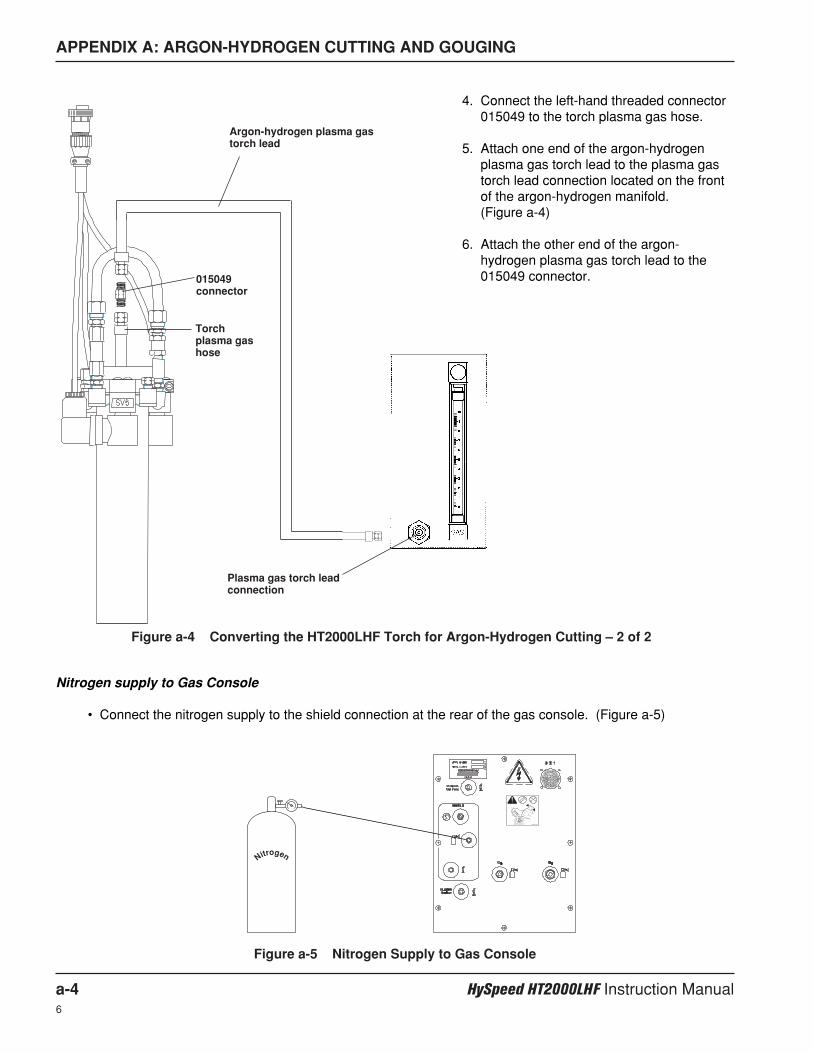
APPENDIX A: ARGON-HYDROGEN CUTTING AND GOUGING
a-4 HySpeed HT2000LHF Instruction Manual6
Figure a-5 Nitrogen Supply to Gas Console
Nitrogen supply to Gas Console
• Connect the nitrogen supply to the shield connection at the rear of the gas console. (Figure a-5)
Nitrogen
2WRENCHES
4. Connect the left-hand threaded connector015049 to the torch plasma gas hose.
5. Attach one end of the argon-hydrogenplasma gas torch lead to the plasma gastorch lead connection located on the frontof the argon-hydrogen manifold. (Figure a-4)
6. Attach the other end of the argon-hydrogen plasma gas torch lead to the015049 connector.
Plasma gas torch leadconnection
015049connector
Torchplasma gashose
Argon-hydrogen plasma gastorch lead
Figure a-4 Converting the HT2000LHF Torch for Argon-Hydrogen Cutting – 2 of 2

APPENDIX A: ARGON-HYDROGEN CUTTING AND GOUGING
HySpeed HT2000LHF Instruction Manual a-56
WARNING
Before operating this system, you must read the Safety section thoroughly! Verify main disconnectswitch to the power supply is OFF before proceeding with the following steps
Operation
Prior to operation, ensure that your cutting environment and that your clothing meet the safety requirementsoutlined in the Safety section of this manual. If problems occur during operation, refer to the Installation portion ofthis section as well as Section 3.
Note: For operation without argon-hydrogen manifold, see Section 4: Operation.
Check Torch
1. Remove the consumables from the torch and check for worn or damaged parts. Always place theconsumables on a clean, dry, oil-free surface after removing. Dirty consumables can cause thetorch to malfunction.
• Check the pit depth of the electrode. The electrode should be replaced when the depth exceeds .044 inch (1.1 mm).
• Wipe the current ring in the torch with a clean paper towel or Q-tip (see Figure 4-7).
• Refer to the Argon-Hydrogen Cut Charts to choose the correct consumables for your cutting needs.
2. Replace the consumable parts. Refer to Changing Consumable Parts in Section 4 for detailed informationon replacing consumables.
3. Ensure that the torch is squared to the material. Refer to Section 3 for the torch alignment procedure.
4. Verify that argon-hydrogen cable 14X1 is connected to the argon-hydrogen manifold.
Turn Gases On
1. Set S2 toggle switch on the gas console to Run.
2. Set S1 switch to the N2/Air position.
3. Turn the argon-hydrogen gas supply and the nitrogen gas supply ON.Verify that the oxygen and air gas supplies remain OFF.
• Adjust the argon-hydrogen plasma gas supply regulator to read 120 psi +/- 10 psi (8.2 bar +/- 0.7 bar).
• Adjust supply regulator for shield gas to read 90 psi +/- 10 psi (6.2 bar +/- 0.7 bar).
PLASMA
N2/Air O2
SHIELD
N2/Air
psi
psipsi
DC
N2/Air
O2
O2PLASMACut Flow PreFlowPreFlow
Run
10
9
8
7
6
5
4
3
2
1
0
10
9
8
7
6
5
4
3
2
1
0
TestPreflow
TestCutflow
HySpeed ® HT2000LHF
®
S1
S2
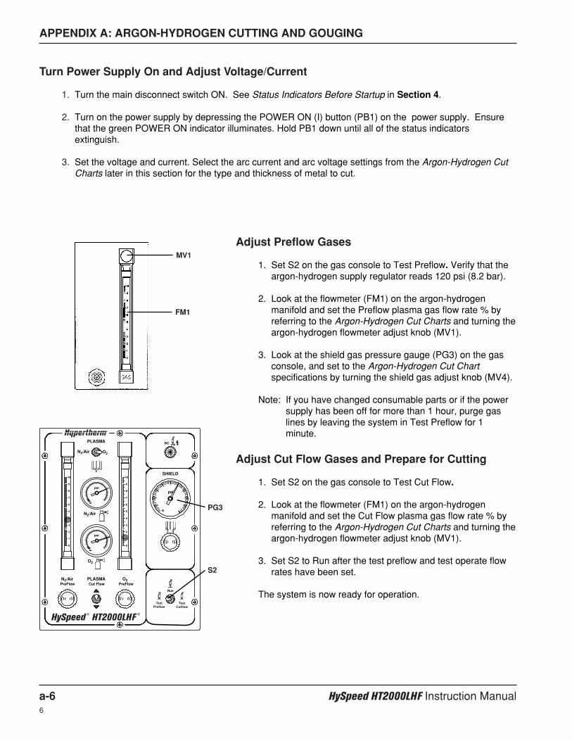
APPENDIX A: ARGON-HYDROGEN CUTTING AND GOUGING
a-6 HySpeed HT2000LHF Instruction Manual6
Turn Power Supply On and Adjust Voltage/Current
1. Turn the main disconnect switch ON. See Status Indicators Before Startup in Section 4.
2. Turn on the power supply by depressing the POWER ON (I) button (PB1) on the power supply. Ensurethat the green POWER ON indicator illuminates. Hold PB1 down until all of the status indicatorsextinguish.
3. Set the voltage and current. Select the arc current and arc voltage settings from the Argon-Hydrogen CutCharts later in this section for the type and thickness of metal to cut.
PLASMA
N2/Air O2
SHIELD
N2/Air
psi
psipsi
DC
N2/Air
O2
O2PLASMACut Flow PreFlowPreFlow
Run
10
9
8
7
6
5
4
3
2
1
0
10
9
8
7
6
5
4
3
2
1
0
TestPreflow
TestCutflow
HySpeed ® HT2000LHF
®
MV1
FM1
S2
PG3
Adjust Preflow Gases
1. Set S2 on the gas console to Test Preflow. Verify that theargon-hydrogen supply regulator reads 120 psi (8.2 bar).
2. Look at the flowmeter (FM1) on the argon-hydrogenmanifold and set the Preflow plasma gas flow rate % byreferring to the Argon-Hydrogen Cut Charts and turning theargon-hydrogen flowmeter adjust knob (MV1).
3. Look at the shield gas pressure gauge (PG3) on the gasconsole, and set to the Argon-Hydrogen Cut Chartspecifications by turning the shield gas adjust knob (MV4).
Note: If you have changed consumable parts or if the powersupply has been off for more than 1 hour, purge gaslines by leaving the system in Test Preflow for 1minute.
Adjust Cut Flow Gases and Prepare for Cutting
1. Set S2 on the gas console to Test Cut Flow.
2. Look at the flowmeter (FM1) on the argon-hydrogenmanifold and set the Cut Flow plasma gas flow rate % byreferring to the Argon-Hydrogen Cut Charts and turning theargon-hydrogen flowmeter adjust knob (MV1).
3. Set S2 to Run after the test preflow and test operate flowrates have been set.
The system is now ready for operation.
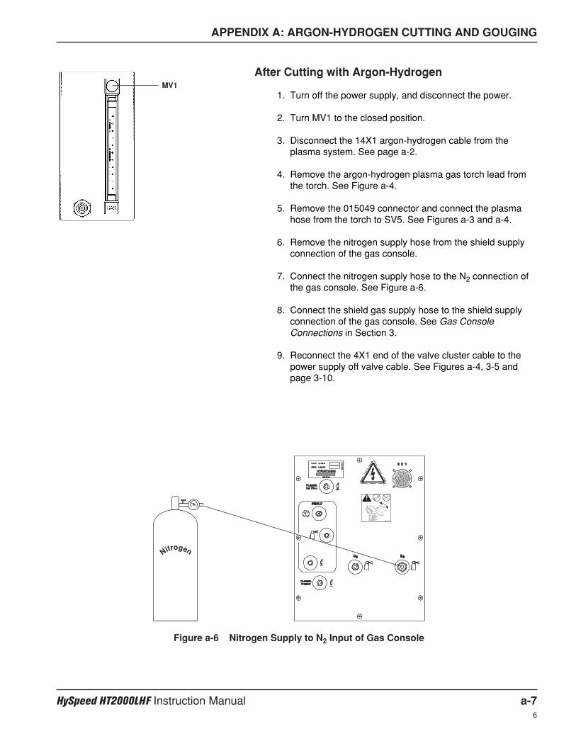
APPENDIX A: ARGON-HYDROGEN CUTTING AND GOUGING
HySpeed HT2000LHF Instruction Manual a-76
After Cutting with Argon-Hydrogen
1. Turn off the power supply, and disconnect the power.
2. Turn MV1 to the closed position.
3. Disconnect the 14X1 argon-hydrogen cable from theplasma system. See page a-2.
4. Remove the argon-hydrogen plasma gas torch lead fromthe torch. See Figure a-4.
5. Remove the 015049 connector and connect the plasmahose from the torch to SV5. See Figures a-3 and a-4.
6. Remove the nitrogen supply hose from the shield supplyconnection of the gas console.
7. Connect the nitrogen supply hose to the N2 connection ofthe gas console. See Figure a-6.
8. Connect the shield gas supply hose to the shield supplyconnection of the gas console. See Gas ConsoleConnections in Section 3.
9. Reconnect the 4X1 end of the valve cluster cable to thepower supply off valve cable. See Figures a-4, 3-5 andpage 3-10.
MV1
Figure a-6 Nitrogen Supply to N2 Input of Gas Console
Nitrogen
2WRENCHES
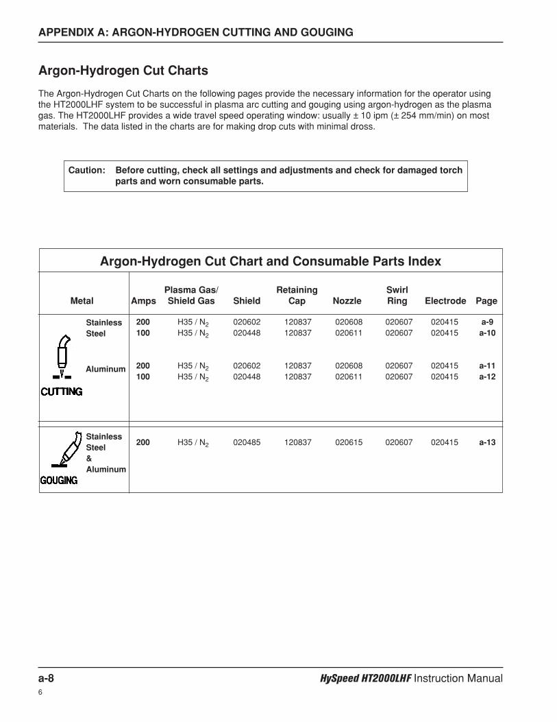
APPENDIX A: ARGON-HYDROGEN CUTTING AND GOUGING
a-8 HySpeed HT2000LHF Instruction Manual6
Argon-Hydrogen Cut Charts
The Argon-Hydrogen Cut Charts on the following pages provide the necessary information for the operator usingthe HT2000LHF system to be successful in plasma arc cutting and gouging using argon-hydrogen as the plasmagas. The HT2000LHF provides a wide travel speed operating window: usually ± 10 ipm (± 254 mm/min) on mostmaterials. The data listed in the charts are for making drop cuts with minimal dross.
Caution: Before cutting, check all settings and adjustments and check for damaged torchparts and worn consumable parts.
Argon-Hydrogen Cut Chart and Consumable Parts Index
Plasma Gas/ Retaining SwirlMetal Amps Shield Gas Shield Cap Nozzle Ring Electrode Page
StainlessSteel
StainlessSteel&Aluminum
Aluminum
200 H35 / N2 020602 120837 020608 020607 020415 a-9100 H35 / N2 020448 120837 020611 020607 020415 a-10
200 H35 / N2 020602 120837 020608 020607 020415 a-11100 H35 / N2 020448 120837 020611 020607 020415 a-12
200 H35 / N2 020485 120837 020615 020607 020415 a-13
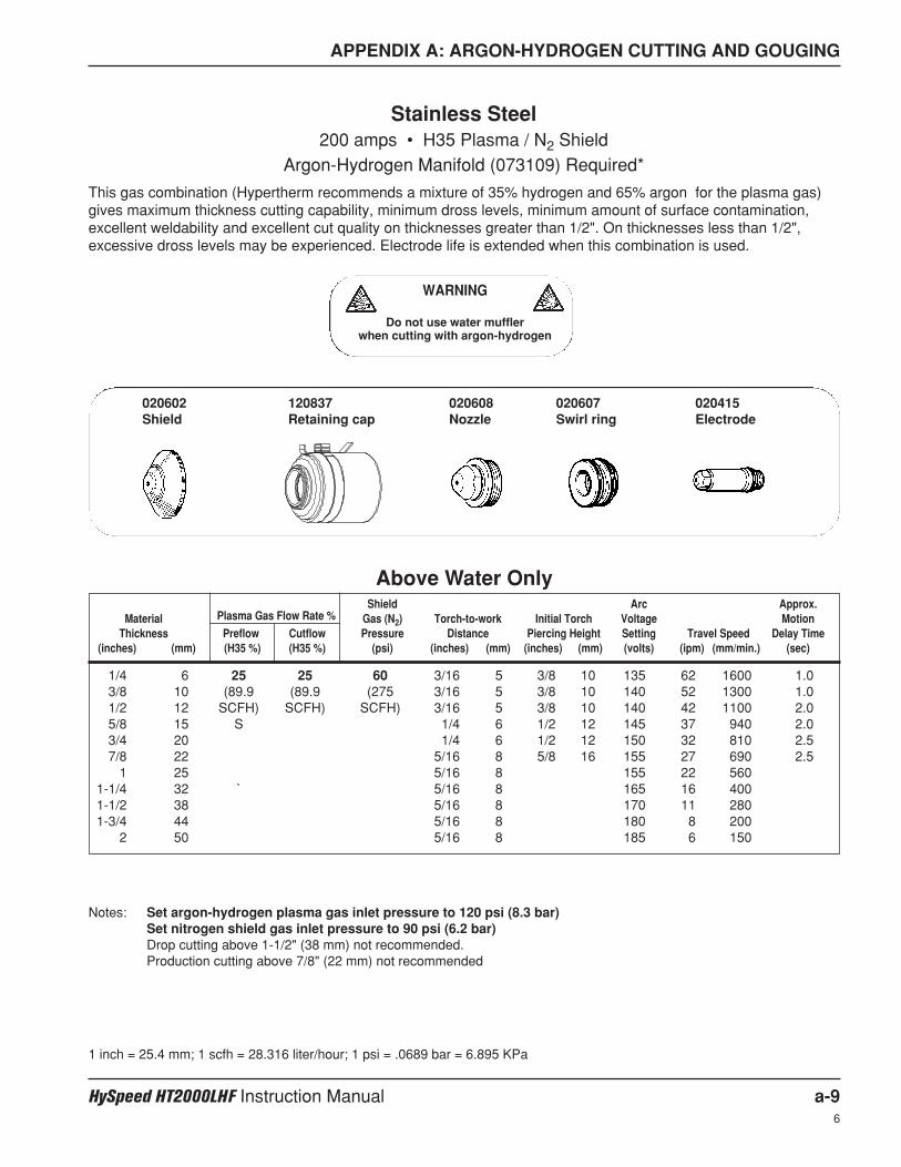
APPENDIX A: ARGON-HYDROGEN CUTTING AND GOUGING
HySpeed HT2000LHF Instruction Manual a-96
Shield Arc Approx.Material Plasma Gas Flow Rate % Gas (N2) Torch-to-work Initial Torch Voltage Motion
Thickness Preflow Cutflow Pressure Distance Piercing Height Setting Travel Speed Delay Time(inches) (mm) (H35 %) (H35 %) (psi) (inches) (mm) (inches) (mm) (volts) (ipm) (mm/min.) (sec)
1/4 6 25 25 60 3/16 5 3/8 10 135 62 1600 1.03/8 10 (89.9 (89.9 (275 3/16 5 3/8 10 140 52 1300 1.01/2 12 SCFH) SCFH) SCFH) 3/16 5 3/8 10 140 42 1100 2.05/8 15 S 1/4 6 1/2 12 145 37 940 2.03/4 20 1/4 6 1/2 12 150 32 810 2.57/8 22 5/16 8 5/8 16 155 27 690 2.5
1 25 5/16 8 155 22 5601-1/4 32 ` 5/16 8 165 16 4001-1/2 38 5/16 8 170 11 2801-3/4 44 5/16 8 180 8 200
2 50 5/16 8 185 6 150
Stainless Steel200 amps • H35 Plasma / N2 Shield
Argon-Hydrogen Manifold (073109) Required*
This gas combination (Hypertherm recommends a mixture of 35% hydrogen and 65% argon for the plasma gas)gives maximum thickness cutting capability, minimum dross levels, minimum amount of surface contamination,excellent weldability and excellent cut quality on thicknesses greater than 1/2". On thicknesses less than 1/2",excessive dross levels may be experienced. Electrode life is extended when this combination is used.
1 inch = 25.4 mm; 1 scfh = 28.316 liter/hour; 1 psi = .0689 bar = 6.895 KPa
Notes: Set argon-hydrogen plasma gas inlet pressure to 120 psi (8.3 bar)Set nitrogen shield gas inlet pressure to 90 psi (6.2 bar)Drop cutting above 1-1/2" (38 mm) not recommended.Production cutting above 7/8" (22 mm) not recommended
Above Water Only
WARNING
Do not use water mufflerwhen cutting with argon-hydrogen
020602Shield
120837Retaining cap
020608Nozzle
020607Swirl ring
020415Electrode
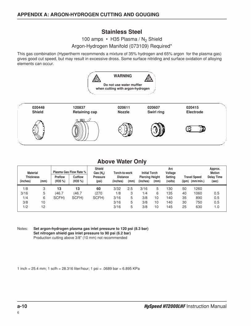
APPENDIX A: ARGON-HYDROGEN CUTTING AND GOUGING
a-10 HySpeed HT2000LHF Instruction Manual6
Shield Arc Approx.Material Plasma Gas Flow Rate % Gas (N2) Torch-to-work Initial Torch Voltage Motion
Thickness Preflow Cutflow Pressure Distance Piercing Height Setting Travel Speed Delay Time(inches) (mm) (H35 %) (H35 %) (psi) (inches) (mm) (inches) (mm) (volts) (ipm) (mm/min.) (sec)
1/8 3 13 13 60 3/32 2.5 3/16 5 130 50 12603/16 5 (46.7 (46.7 (270 1/8 3 1/4 6 135 40 1060 0.51/4 6 SCFH) SCFH) SCFH) 3/16 5 3/8 10 140 35 890 0.53/8 10 3/16 5 3/8 10 140 30 750 0.51/2 12 3/16 5 3/8 10 145 25 630 1.0
Stainless Steel100 amps • H35 Plasma / N2 Shield
Argon-Hydrogen Manifold (073109) Required*
This gas combination (Hypertherm recommends a mixture of 35% hydrogen and 65% argon for the plasma gas)gives good cut speed, but may result in excessive dross. Some surface nitriding and surface oxidation of alloyingelements can occur.
1 inch = 25.4 mm; 1 scfh = 28.316 liter/hour; 1 psi = .0689 bar = 6.895 KPa
Notes: Set argon-hydrogen plasma gas inlet pressure to 120 psi (8.3 bar)Set nitrogen shield gas inlet pressure to 90 psi (6.2 bar)Production cutting above 3/8" (10 mm) not recommended
Above Water Only
020448Shield
120837Retaining cap
020611Nozzle
020607Swirl ring
020415Electrode
WARNING
Do not use water mufflerwhen cutting with argon-hydrogen
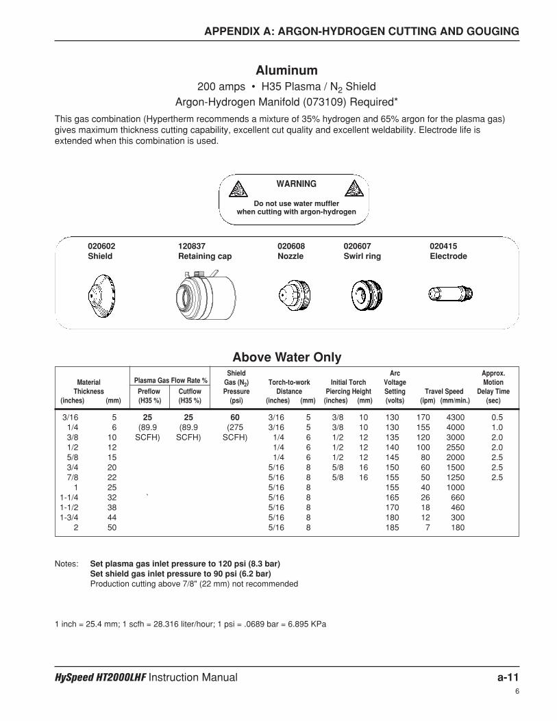
APPENDIX A: ARGON-HYDROGEN CUTTING AND GOUGING
HySpeed HT2000LHF Instruction Manual a-116
Shield Arc Approx.Material Plasma Gas Flow Rate % Gas (N2) Torch-to-work Initial Torch Voltage Motion
Thickness Preflow Cutflow Pressure Distance Piercing Height Setting Travel Speed Delay Time(inches) (mm) (H35 %) (H35 %) (psi) (inches) (mm) (inches) (mm) (volts) (ipm) (mm/min.) (sec)
3/16 5 25 25 60 3/16 5 3/8 10 130 170 4300 0.51/4 6 (89.9 (89.9 (275 3/16 5 3/8 10 130 155 4000 1.03/8 10 SCFH) SCFH) SCFH) 1/4 6 1/2 12 135 120 3000 2.01/2 12 1/4 6 1/2 12 140 100 2550 2.05/8 15 1/4 6 1/2 12 145 80 2000 2.53/4 20 5/16 8 5/8 16 150 60 1500 2.57/8 22 5/16 8 5/8 16 155 50 1250 2.5
1 25 5/16 8 155 40 10001-1/4 32 ` 5/16 8 165 26 6601-1/2 38 5/16 8 170 18 4601-3/4 44 5/16 8 180 12 300
2 50 5/16 8 185 7 180
Aluminum200 amps • H35 Plasma / N2 Shield
Argon-Hydrogen Manifold (073109) Required*
This gas combination (Hypertherm recommends a mixture of 35% hydrogen and 65% argon for the plasma gas)gives maximum thickness cutting capability, excellent cut quality and excellent weldability. Electrode life isextended when this combination is used.
1 inch = 25.4 mm; 1 scfh = 28.316 liter/hour; 1 psi = .0689 bar = 6.895 KPa
Notes: Set plasma gas inlet pressure to 120 psi (8.3 bar)Set shield gas inlet pressure to 90 psi (6.2 bar)Production cutting above 7/8" (22 mm) not recommended
Above Water Only
020602Shield
120837Retaining cap
020608Nozzle
020607Swirl ring
020415Electrode
WARNING
Do not use water mufflerwhen cutting with argon-hydrogen
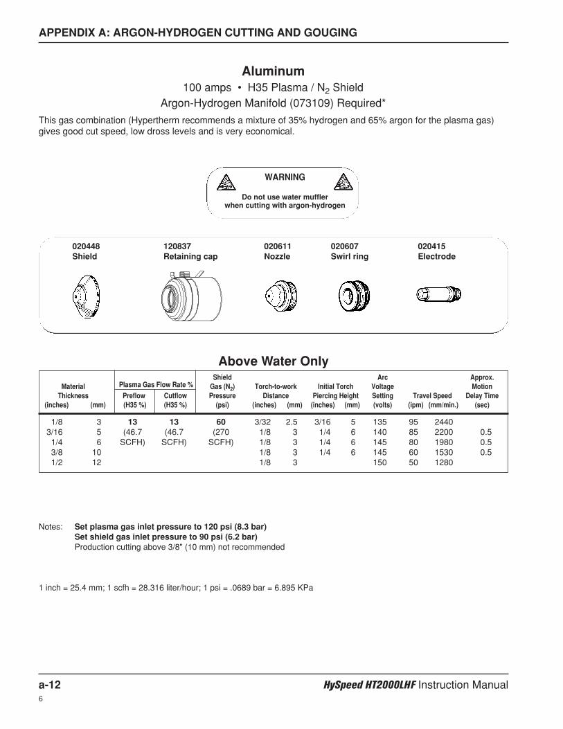
APPENDIX A: ARGON-HYDROGEN CUTTING AND GOUGING
a-12 HySpeed HT2000LHF Instruction Manual6
Shield Arc Approx.Material Plasma Gas Flow Rate % Gas (N2) Torch-to-work Initial Torch Voltage Motion
Thickness Preflow Cutflow Pressure Distance Piercing Height Setting Travel Speed Delay Time(inches) (mm) (H35 %) (H35 %) (psi) (inches) (mm) (inches) (mm) (volts) (ipm) (mm/min.) (sec)
1/8 3 13 13 60 3/32 2.5 3/16 5 135 95 24403/16 5 (46.7 (46.7 (270 1/8 3 1/4 6 140 85 2200 0.51/4 6 SCFH) SCFH) SCFH) 1/8 3 1/4 6 145 80 1980 0.53/8 10 1/8 3 1/4 6 145 60 1530 0.51/2 12 1/8 3 150 50 1280
Aluminum100 amps • H35 Plasma / N2 Shield
Argon-Hydrogen Manifold (073109) Required*
This gas combination (Hypertherm recommends a mixture of 35% hydrogen and 65% argon for the plasma gas)gives good cut speed, low dross levels and is very economical.
1 inch = 25.4 mm; 1 scfh = 28.316 liter/hour; 1 psi = .0689 bar = 6.895 KPa
Notes: Set plasma gas inlet pressure to 120 psi (8.3 bar)Set shield gas inlet pressure to 90 psi (6.2 bar)Production cutting above 3/8" (10 mm) not recommended
Above Water Only
020448Shield
120837Retaining cap
020611Nozzle
020607Swirl ring
020415Electrode
WARNING
Do not use water mufflerwhen cutting with argon-hydrogen
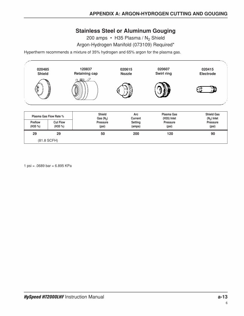
APPENDIX A: ARGON-HYDROGEN CUTTING AND GOUGING
HySpeed HT2000LHF Instruction Manual a-136
Shield Arc Plasma Gas Shield GasPlasma Gas Flow Rate %
Gas (N2) Current (H35) Inlet (N2) InletPreflow Cut Flow Pressure Setting Pressure Pressure(H35 %) (H35 %) (psi) (amps) (psi) (psi)
1 psi = .0689 bar = 6.895 KPa
29 29 50 200 120 90
(81.8 SCFH)
Stainless Steel or Aluminum Gouging200 amps • H35 Plasma / N2 Shield
Argon-Hydrogen Manifold (073109) Required*
Hypertherm recommends a mixture of 35% hydrogen and 65% argon for the plasma gas.
020607Swirl ring
020415Electrode
020615Nozzle
120837Retaining cap
020485Shield

HySpeed HT200LHF Instruction Manual b-119
Appendix B
PROPYLENE GLYCOL SAFETY DATABENZOTRIAZOLE SAFETY DATA
In this section:
Propylene Glycol Safety DataSection 1 Chemical Product and Company Identification .............................................................................b-2Section 2 Information on Ingredients ............................................................................................................b-2Section 3 Hazards Identification....................................................................................................................b-2Section 4 First Aid Measures ........................................................................................................................b-3Section 5 Fire Fighting Measures .................................................................................................................b-3Section 6 Accidental Release Measures.......................................................................................................b-3Section 7 Handling and Storage ...................................................................................................................b-3Section 8 Exposure Controls / Personal Protection ......................................................................................b-4Section 9 Physical and Chemical Properties ................................................................................................b-4Section 10 Stability and Reactivity ..................................................................................................................b-4Section 11 Toxicological Information ...............................................................................................................b-4Section 12 Ecological Information...................................................................................................................b-5Section 13 Disposal Considerations ...............................................................................................................b-5Section 14 Transport Information ....................................................................................................................b-5Section 15 Regulatory Information..................................................................................................................b-5Section 16 Other Information ..........................................................................................................................b-5
Benzotriazole (COBRATEC) Safety DataSection I ..........................................................................................................................................................b-7Section II Ingredients ......................................................................................................................................b-7Section III Physical Data .................................................................................................................................b-7Section IV Fire and Explosion Hazard Data....................................................................................................b-8Section V Health Hazard Data ........................................................................................................................b-8Section VI Reactivity Data...............................................................................................................................b-9Section VII Spill or Leak Procedures...............................................................................................................b-9Section VIII Special Protective Information .....................................................................................................b-9Section IX Special Precautions .....................................................................................................................b-10Section X Regulatory Status .........................................................................................................................b-10
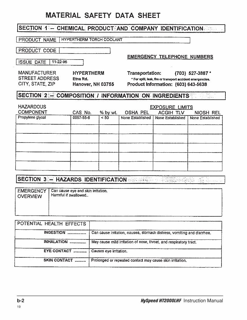
b-2 HySpeed HT2000LHF Instruction Manual19
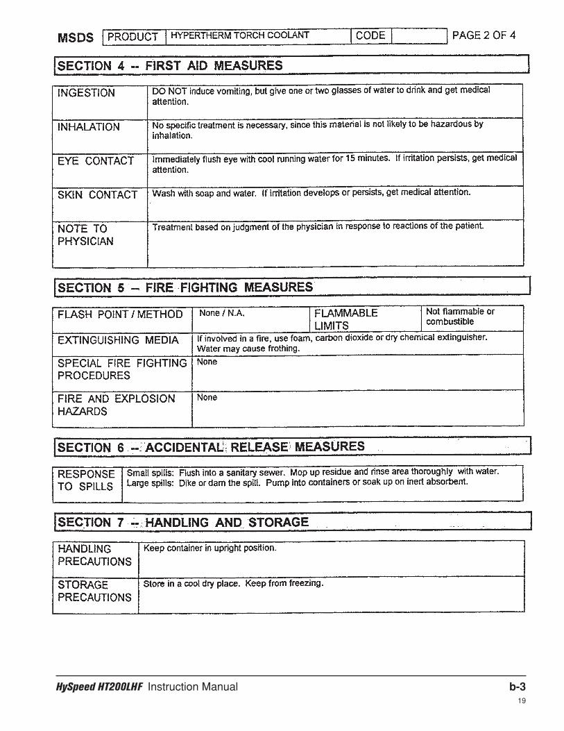
HySpeed HT200LHF Instruction Manual b-319
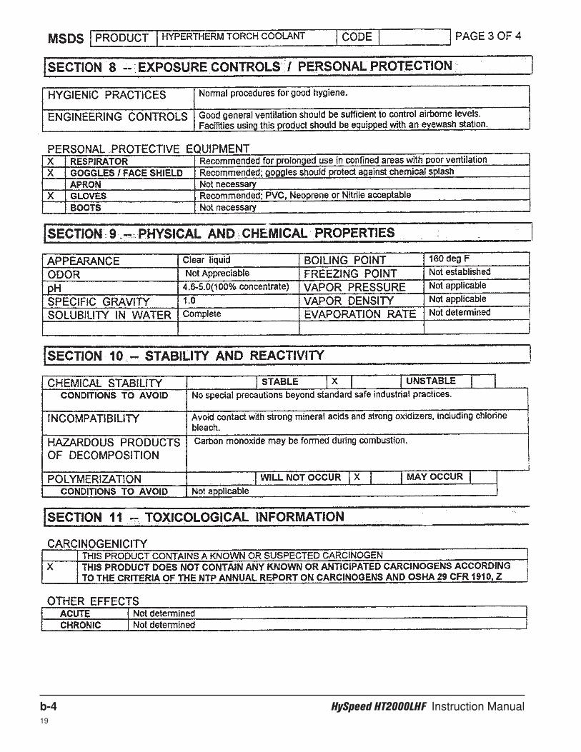
b-4 HySpeed HT2000LHF Instruction Manual19
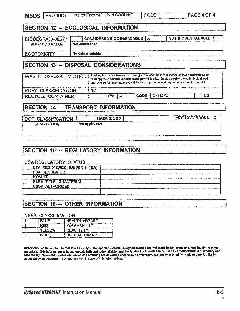
HySpeed HT200LHF Instruction Manual b-519
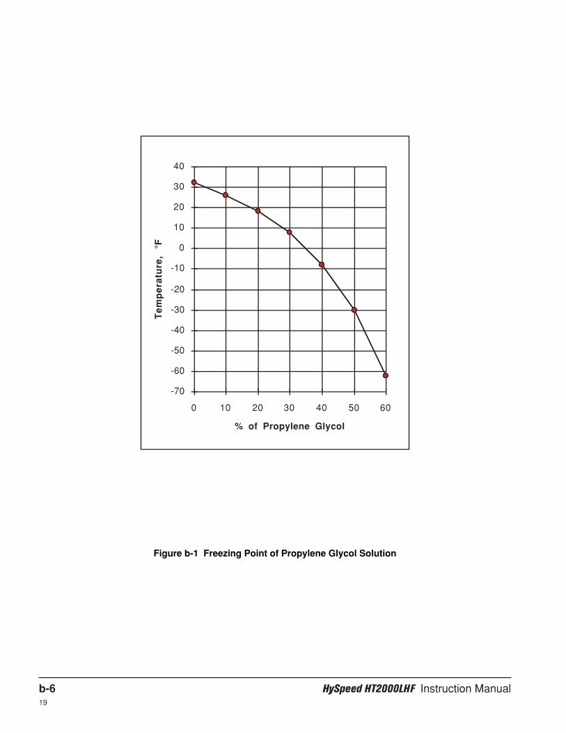
b-6 HySpeed HT2000LHF Instruction Manual19
Figure b-1 Freezing Point of Propylene Glycol Solution
% of Propylene Glycol
Te
mp
era
ture
, °F
-70
-60
-50
-40
-30
-20
-10
0
10
20
30
40
0 10 20 30 40 50 60
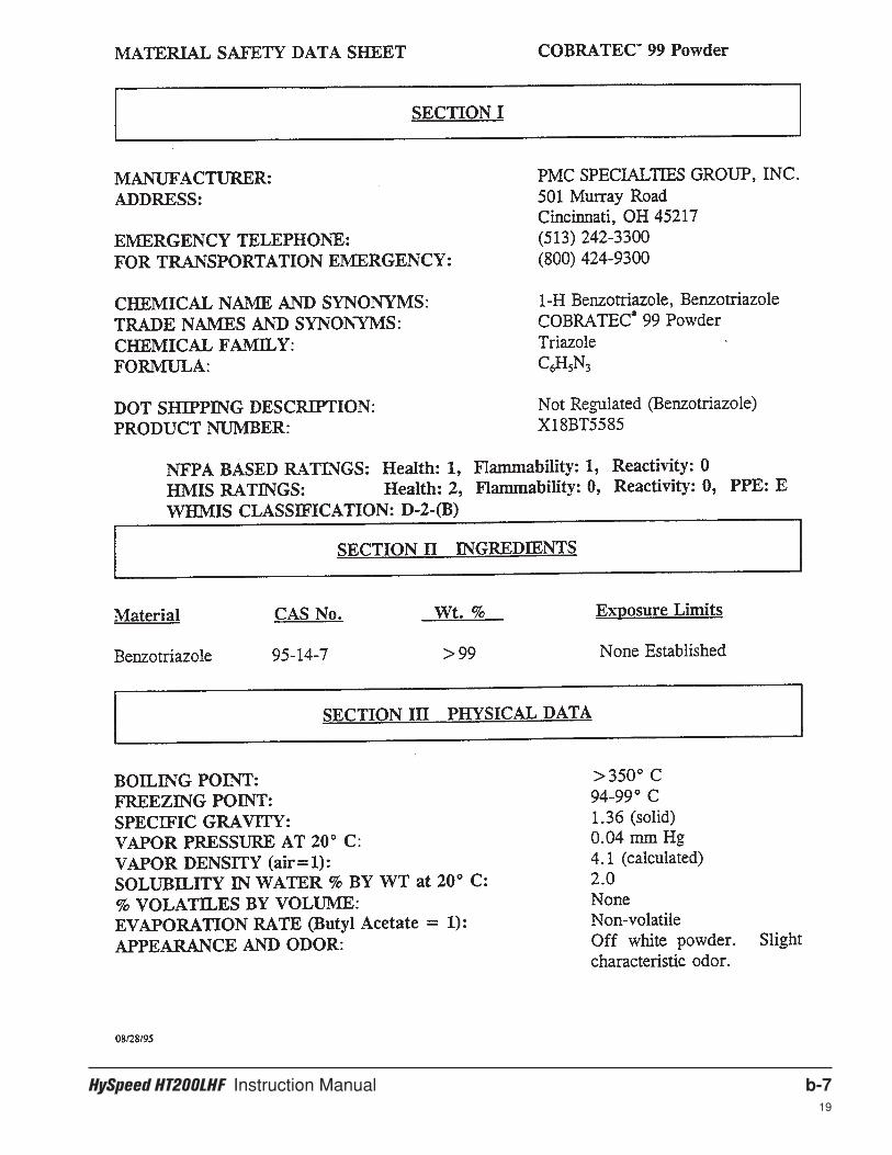
HySpeed HT200LHF Instruction Manual b-719
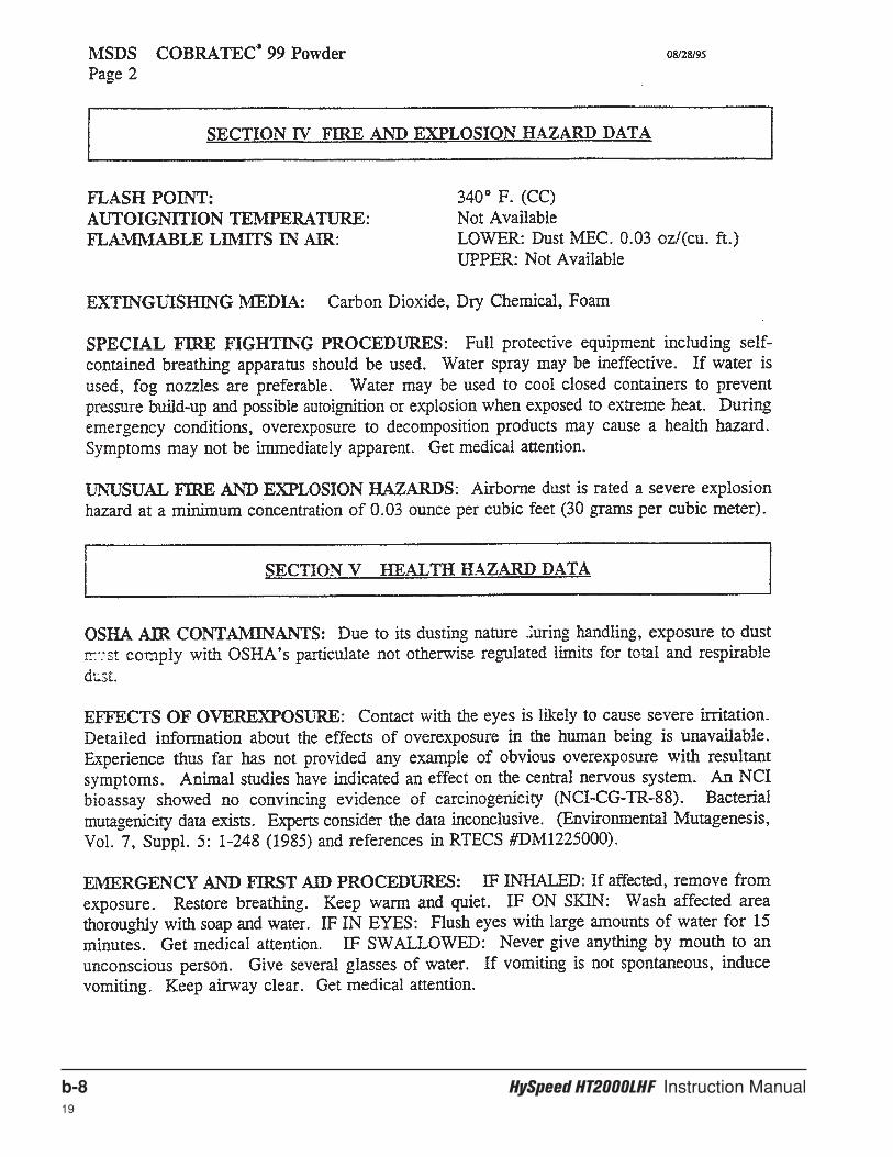
b-8 HySpeed HT2000LHF Instruction Manual19
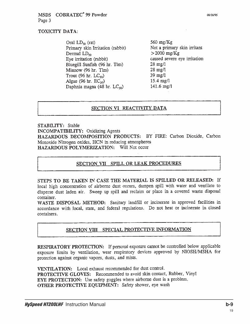
HySpeed HT200LHF Instruction Manual b-919
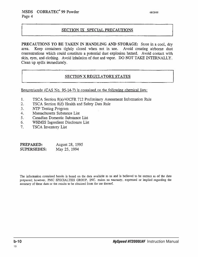
b-10 HySpeed HT2000LHF Instruction Manual19
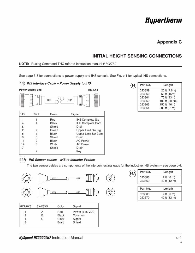
HySpeed HT2000LHF Instruction Manual c-16
Appendix C
INITIAL HEIGHT SENSING CONNECTIONS
NOTE: If using Command THC refer to Instruction manual # 802780
See page 3-8 for connections to power supply and IHS console. See Fig. c-1 for typical IHS connections.
IHS Interface Cable – Power Supply to IHS14
8X1
Power Supply End IHS End
1X9
1X9 8X1 Color Signal
1 1 Red IHS Complete Sig4 4 Black IHS Complete Com8 Shield Drain2 2 Green Upper Limit Sw Sig5 3 Black Upper Limit Sw Com9 5 Shield Drain11 9 Black AC Power14 8 White AC Power7 Shield Drain
7 Key
8X2/8X3 8X4/8X5 Color Signal
4 A Red Power (+15 VDC)2 B Black Common1 C Clear Signal3 Braid Shield
14 Part No. Length
023859 25 ft (7.6m)023860 50 ft (15m)023861 75 ft (23m)023862 100 ft (30.5m)023863 150 ft (46m)023864 200 ft (61m)
IHS Sensor cables – IHS to Inductor Probes
The two sensor cables are components of the interconnecting leads for the inductive IHS system – see page c-4.
Part No. Length
023888 2 ft (.6 m)023869 40 ft (12 m)
Part No. Length
023889 2 ft (.6 m)023870 40 ft (12 m)
8X2
8X3
8X4
8X5
14A
14A
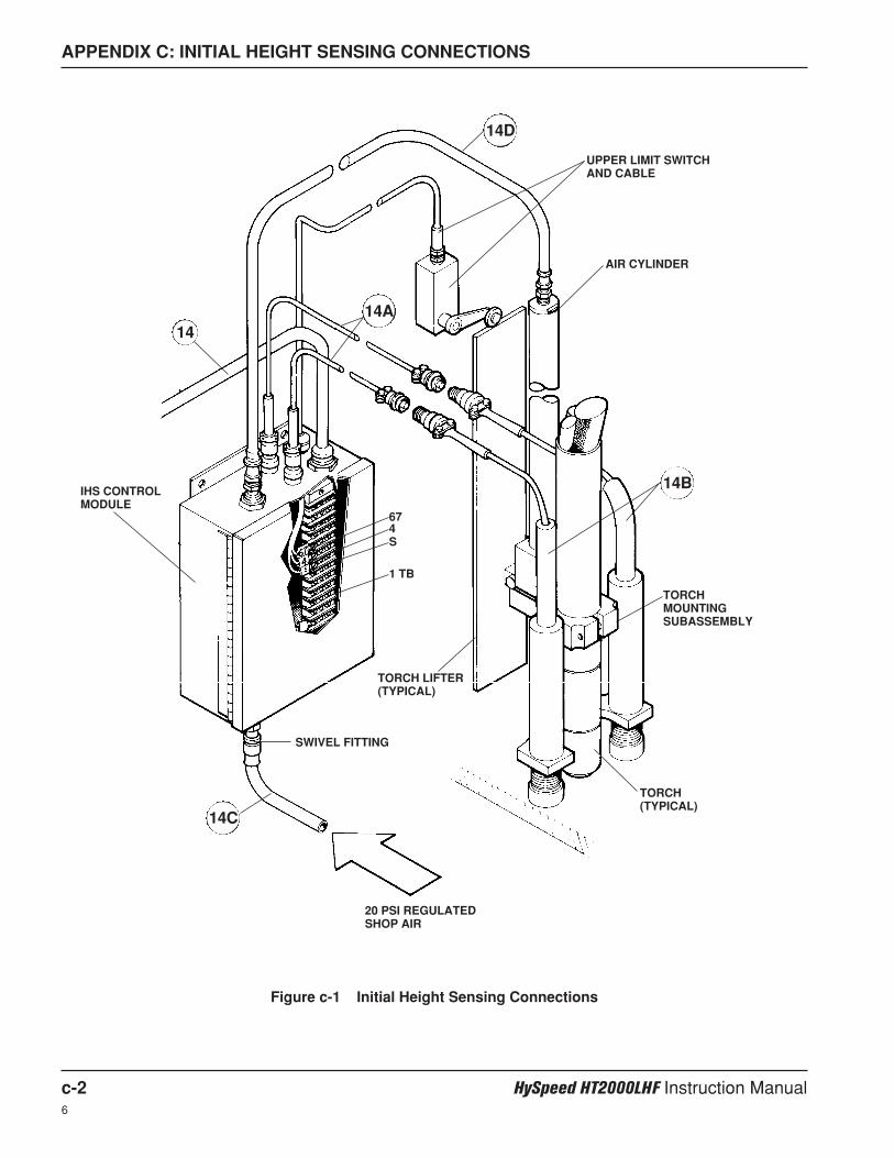
APPENDIX C: INITIAL HEIGHT SENSING CONNECTIONS
c-2 HySpeed HT2000LHF Instruction Manual6
Figure c-1 Initial Height Sensing Connections
AIR CYLINDER
TORCHMOUNTINGSUBASSEMBLY
TORCH(TYPICAL)
SWIVEL FITTING
IHS CONTROLMODULE
20 PSI REGULATEDSHOP AIR
TORCH LIFTER(TYPICAL)
14D
14A
14B
14C
14
UPPER LIMIT SWITCHAND CABLE
674S
1 TB
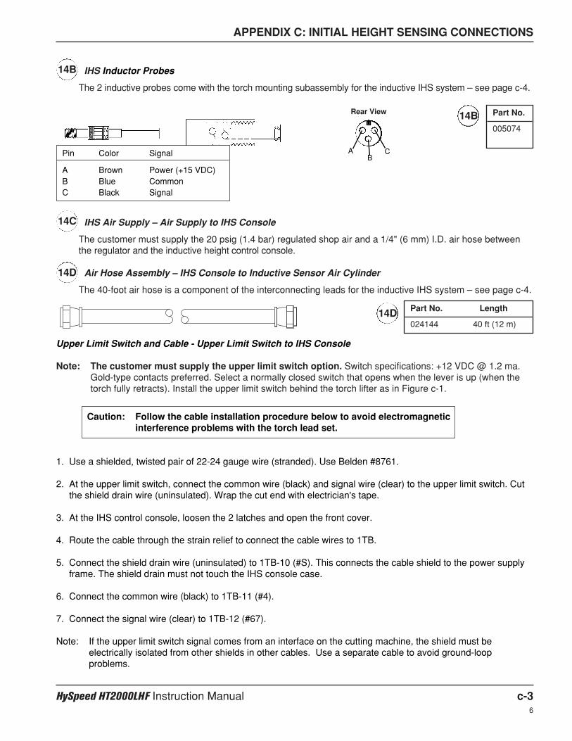
IHS Air Supply – Air Supply to IHS Console
The customer must supply the 20 psig (1.4 bar) regulated shop air and a 1/4" (6 mm) I.D. air hose betweenthe regulator and the inductive height control console.
Air Hose Assembly – IHS Console to Inductive Sensor Air Cylinder
The 40-foot air hose is a component of the interconnecting leads for the inductive IHS system – see page c-4.
APPENDIX C: INITIAL HEIGHT SENSING CONNECTIONS
HySpeed HT2000LHF Instruction Manual c-36
14B
14B
IHS Inductor Probes
The 2 inductive probes come with the torch mounting subassembly for the inductive IHS system – see page c-4.
14C
14D
14D
Part No.
005074
AB
C
Rear View
Pin Color Signal
A Brown Power (+15 VDC)B Blue CommonC Black Signal
Part No. Length
024144 40 ft (12 m)
Upper Limit Switch and Cable - Upper Limit Switch to IHS Console
Note: The customer must supply the upper limit switch option. Switch specifications: +12 VDC @ 1.2 ma.Gold-type contacts preferred. Select a normally closed switch that opens when the lever is up (when thetorch fully retracts). Install the upper limit switch behind the torch lifter as in Figure c-1.
Caution: Follow the cable installation procedure below to avoid electromagneticinterference problems with the torch lead set.
1. Use a shielded, twisted pair of 22-24 gauge wire (stranded). Use Belden #8761.
2. At the upper limit switch, connect the common wire (black) and signal wire (clear) to the upper limit switch. Cutthe shield drain wire (uninsulated). Wrap the cut end with electrician's tape.
3. At the IHS control console, loosen the 2 latches and open the front cover.
4. Route the cable through the strain relief to connect the cable wires to 1TB.
5. Connect the shield drain wire (uninsulated) to 1TB-10 (#S). This connects the cable shield to the power supplyframe. The shield drain must not touch the IHS console case.
6. Connect the common wire (black) to 1TB-11 (#4).
7. Connect the signal wire (clear) to 1TB-12 (#67).
Note: If the upper limit switch signal comes from an interface on the cutting machine, the shield must beelectrically isolated from other shields in other cables. Use a separate cable to avoid ground-loopproblems.
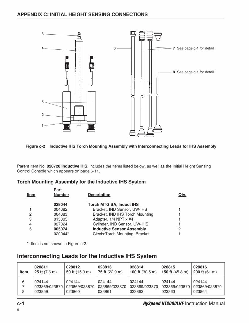
APPENDIX C: INITIAL HEIGHT SENSING CONNECTIONS
c-4 HySpeed HT2000LHF Instruction Manual6
028811 028812 028813 028814 028815 028816Item 25 ft (7.6 m) 50 ft (15.3 m) 75 ft (22.9 m) 100 ft (30.5 m) 150 ft (45.8 m) 200 ft (61 m)
6 024144 024144 024144 024144 024144 0241447 023869/023870 023869/023870 023869/023870 023869/023870 023869/023870 023869/0238708 023859 023860 023861 023862 023863 023864
PartItem Number Description Qty.
029044 Torch MTG SA, Induct IHS 1 004082 Bracket, IND Sensor, UW-IHS 12 004083 Bracket, IND IHS Torch Mounting 13 015005 Adapter, 1/4 NPT x #4 14 027024 Cylinder, IND Sensor, UW-IHS 15 005074 Inductive Sensor Assembly 2
020044* Clevis:Torch Mounting Bracket 1
* Item is not shown in Figure c-2.
Figure c-2 Inductive IHS Torch Mounting Assembly with Interconnecting Leads for IHS Assembly
Interconnecting Leads for the Inductive IHS System
Torch Mounting Assembly for the Inductive IHS System
Parent Item No. 028720 Inductive IHS, includes the items listed below, as well as the Initial Height SensingControl Console which appears on page 6-11.
1
2
3
4
5
6 7 See page c-1 for detail
8 See page c-1 for detail

HySpeed HT2000LHF Instruction Manual d-16
Appendix D
ELECTROMAGNETIC COMPATIBILITY
General
This appendix will enable a qualified electrician to install the power cable to the EMI filter on the 400V CE powersupplies (073235, 073236).
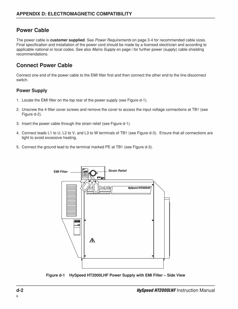
APPENDIX D: ELECTROMAGNETIC COMPATIBILITY
d-2 HySpeed HT2000LHF Instruction Manual6
Power Cable
The power cable is customer supplied. See Power Requirements on page 3-4 for recommended cable sizes.Final specification and installation of the power cord should be made by a licensed electrician and according toapplicable national or local codes. See also Mains Supply on page i for further power (supply) cable shieldingrecommendations.
Connect Power Cable
Connect one end of the power cable to the EMI filter first and then connect the other end to the line disconnectswitch.
Power Supply
1. Locate the EMI filter on the top rear of the power supply (see Figure d-1).
2. Unscrew the 4 filter cover screws and remove the cover to access the input voltage connections at TB1 (seeFigure d-2).
3. Insert the power cable through the strain relief (see Figure d-1).
4. Connect leads L1 to U, L2 to V, and L3 to W terminals of TB1 (see Figure d-3). Ensure that all connections aretight to avoid excessive heating.
5. Connect the ground lead to the terminal marked PE at TB1 (see Figure d-3).
Figure d-1 HySpeed HT2000LHF Power Supply with EMI Filter – Side View
EMI Filter Strain Relief
HySpeed HT2000LHF
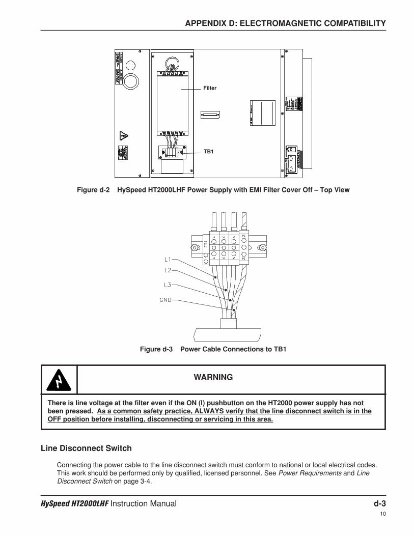
APPENDIX D: ELECTROMAGNETIC COMPATIBILITY
HySpeed HT2000LHF Instruction Manual d-310
Figure d-2 HySpeed HT2000LHF Power Supply with EMI Filter Cover Off – Top View
Filter
TB1
Line Disconnect Switch
Connecting the power cable to the line disconnect switch must conform to national or local electrical codes.This work should be performed only by qualified, licensed personnel. See Power Requirements and LineDisconnect Switch on page 3-4.
Figure d-3 Power Cable Connections to TB1
WARNING
There is line voltage at the filter even if the ON (l) pushbutton on the HT2000 power supply has notbeen pressed. As a common safety practice, ALWAYS verify that the line disconnect switch is in theOFF position before installing, disconnecting or servicing in this area.
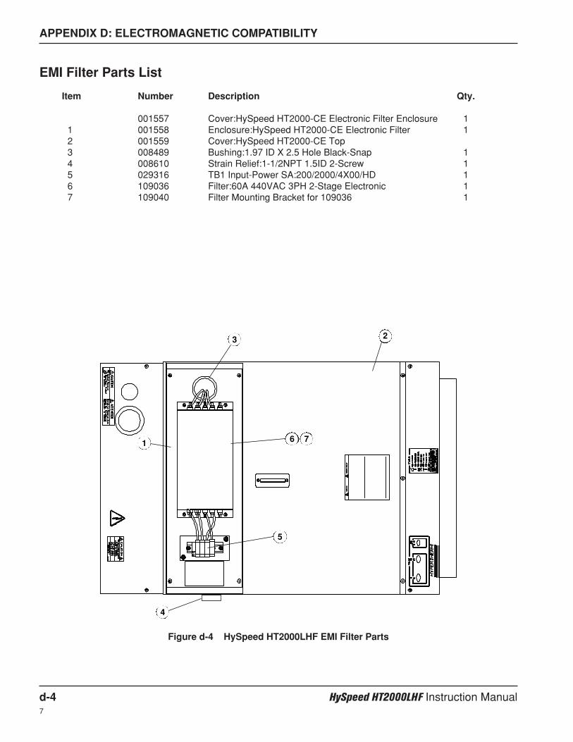
APPENDIX D: ELECTROMAGNETIC COMPATIBILITY
d-4 HySpeed HT2000LHF Instruction Manual7
EMI Filter Parts List
Item Number Description Qty.
001557 Cover:HySpeed HT2000-CE Electronic Filter Enclosure 11 001558 Enclosure:HySpeed HT2000-CE Electronic Filter 12 001559 Cover:HySpeed HT2000-CE Top3 008489 Bushing:1.97 ID X 2.5 Hole Black-Snap 14 008610 Strain Relief:1-1/2NPT 1.5ID 2-Screw 15 029316 TB1 Input-Power SA:200/2000/4X00/HD 16 109036 Filter:60A 440VAC 3PH 2-Stage Electronic 17 109040 Filter Mounting Bracket for 109036 1
1
3 2
4
5
6 7
Figure d-4 HySpeed HT2000LHF EMI Filter Parts
HySpeed HT2000LHF Instruction Manual e-16
Appendix E
AIR FILTERS
Air Filters
Gas purity is critical for maximizing consumable parts life, as well as for producing the highest quality cutting whichHypertherm plasma equipment can achieve. Plasma air must be clean, dry and oil-free, and air must be deliveredat the pressure and flow rate specified for each plasma system. If the air supply contains moisture, oil or dirtparticles, cut quality will be lowered and consumable parts life will be shortened, which increase production costs.
To optimize both consumables life and cut quality, Hypertherm recommends a three-stage filtering process forcompressor air for removing contaminants from the air supply.
1. The first stage of filtering should remove at least 99% of all particles and liquids 5 microns and larger in size.
2. The second stage should be a coalescing-type filter to remove oil. This filter should remove 99.99% of particles0.025 micron and larger in size.
3. The third and final stage of filtration should be an activated carbon adsorbent filter that removes 99.999% of oilor hydrocarbons that have not been trapped by the previous stages.

HySpeed HT2000LHF Instruction Manual f-17
Appendix F
AERATION MANIFOLD FOR PLASMA CUTTING ALUMINUM
Introduction
When plasma arc cutting aluminum, free hydrogen gas may be generated by the cutting process. The hightemperature of the plasma process causes disassociation of oxygen and hydrogen from the water in the watertable. The hot aluminum, which has a high affinity for oxygen, then combines with the oxygen leaving freehydrogen.
An effective means of avoiding free hydrogen buildup is to install an aeration manifold on the floor of the watertable to replenish the oxygen content of the water.
Making an Aeration Manifold
Make an aeration manifold with two-inch (50 mm) PVC tubing with one-inch (25 mm) distribution lines connected toit. Drill 1/8 inch (3 mm) holes every six inches (150 mm) in the distribution lines. Cap the ends of the distributionlines and install the lines so that oxygen is delivered to all parts of the cutting area.
Connect the manifold to a shop air line. Set a pressure regulator to obtain a steady stream of bubbles.
Aeration Manifold
Distribution Lines
Regulated air in
Figure f-1 Aeration Manifold
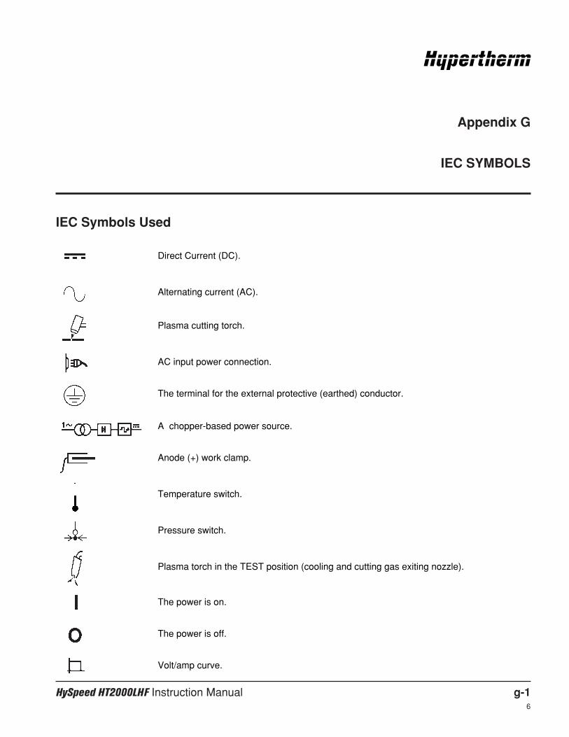
HySpeed HT2000LHF Instruction Manual g-16
Appendix G
IEC SYMBOLS
IEC Symbols Used
Direct Current (DC).
Alternating current (AC).
Plasma cutting torch.
AC input power connection.
The terminal for the external protective (earthed) conductor.
A chopper-based power source.
Anode (+) work clamp.
Temperature switch.
Pressure switch.
Plasma torch in the TEST position (cooling and cutting gas exiting nozzle).
The power is on.
The power is off.
Volt/amp curve.

HySpeed HT2000LHF Instruction Manual h-17
System Grounding RequirementsThe plasma system must be grounded for safety reasons and to suppress EMI:
• Safety The entire system – power supply, accessory enclosures, and worktable – must be grounded toprotect it and the operator from a ground fault. The protective earth (PE) ground connections must beinstalled by a licensed electrician and conform to national and local codes.
• EMI Suppression If allowed by national and local codes, the ground system can also be used to suppressEMI (electromagnetic interference). Below is a guide to configure the plasma system for minimal EMI. SeeElectromagnetic Compatibility in this manual for additional information.
Suggested Ground Cable Routing
Power Supply
Connect the power supply to the PE ground terminal, using a properly sized color-coded conductor. This PEground is connected to the service ground through the line disconnect switch. See the Installation section forfurther information on the power cord and the line disconnect switch.
Equipment Grounding
All accessory modules that receive power from the plasma power supply must also use the power supply’sground – either by connection to the PE terminal of the power supply, or by direct connection to theequipment ground conductor. Each module should have only one connection to ground to avoid ground loops.If any enclosure is grounded to the work table, the work table must be grounded to the power supply.
Effective grounding for EMI reduction is highly dependent upon the installation configuration. Two acceptableconfigurations are shown in Figures h-1 and h-2.
The RHF console should be installed near the work table, and grounded directly to it. Other modules shouldbe installed near the power supply, and grounded directly to it (Figure h-1).
All modules may also be installed near the work table, and grounded directly to it (Figure h-2). Do not groundthe RHF console directly to the power supply.
The customer must furnish all conductors for equipment grounding. Grounding conductors may be purchasedthrough Hypertherm in any length specified by the customer (Part No. 047058). The conductor may also be
Appendix H
SYSTEM GROUNDING
APPENDIX H – SYSTEM GROUNDING
h-2 HySpeed HT2000LHF Instruction Manual6
purchased locally, using a minimum 8 AWG UL Type MTW cable (USA specification) or the appropriate cablespecified by national and local codes.
Consult the appropriate manufacturer’s instructions to ground equipment that does not receive power from thepower supply.
Work Table Grounding
If a supplementary ground rod is installed near the worktable to reduce EMI, it must be connected directly tothe PE ground of the building structure, connected to the service ground; or to earth, providing the resistancebetween the ground rod and the service ground meets national or local codes. Place the supplementaryground rod within 20 ft (6 m) of the worktable according to national or local codes.
If any module is grounded to the work table, the work table must be grounded to the power supply, or theconfiguration must be changed to comply with applicable national and local electrical codes.
A ferrite choke can be placed in the conductor between the work table ground rod and the PE ground, with anumber of turns through the choke to isolate the safety ground (at 60 Hz) from any electromagneticinterference (frequencies above 150 Khz). The more turns the better. A suitable ferrite choke can be made bywrapping 10 turns or more of the ground lead through Magnetics part number 77109-A7, Fair-Rite partnumber 59-77011101, or other equivalent ferrite choke. Locate the choke as close as possible to the plasmapower supply.
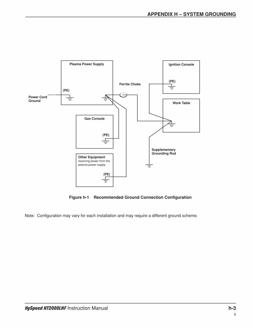
APPENDIX H – SYSTEM GROUNDING
HySpeed HT2000LHF Instruction Manual h-36
Figure h-1 Recommended Ground Connection Configuration
Note: Configuration may vary for each installation and may require a different ground scheme.
Plasma Power Supply
(PE)
(PE)
(PE)
(PE)
Power CordGround
Ferrite Choke
SupplementaryGrounding Rod
Gas Console
Other Equipmentreceiving power from theplasma power supply
Ignition Console
Work Table
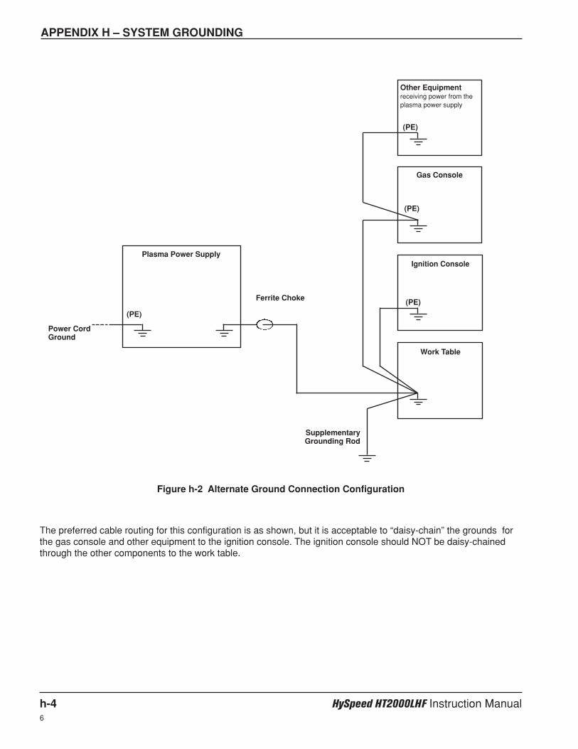
APPENDIX H – SYSTEM GROUNDING
h-4 HySpeed HT2000LHF Instruction Manual6
Figure h-2 Alternate Ground Connection Configuration
The preferred cable routing for this configuration is as shown, but it is acceptable to “daisy-chain” the grounds forthe gas console and other equipment to the ignition console. The ignition console should NOT be daisy-chainedthrough the other components to the work table.
Plasma Power Supply
(PE)
(PE)
Power CordGround
Ferrite Choke
SupplementaryGrounding Rod
Gas Console
Other Equipmentreceiving power from theplasma power supply
Ignition Console
Work Table
(PE)
(PE)