hydronic l-ii boxed enclosure series
TRANSCRIPT

ANTI-IDLING, EMISSION REDUCING EQUIPMENT
Espar Heater Systems
Espar
12 VOLT ASSEMBLIES25.2800.10.1612 HYD 16 L-II Boxed Off-Highway Assembly
25.2800.10.2412 HYD 24 L-II Boxed Off-Highway Assembly
25.2800.10.3012 HYD 30 L-II Boxed Off-Highway Assembly
25.2800.10.3612 HYD 30 L-II Boxed Off-Highway Assembly (6000L Pump)
25.2800.10.3512 HYD 35 L-II Boxed Off-Highway Assembly
24 VOLT ASSEMBLIES25.2800.10.1600 HYD 16 L-II Boxed Off-Highway Assembly
25.2800.10.2400 HYD 24 L-II Boxed Off-Highway Assembly
25.2800.10.3000 HYD 30 L-II Boxed Off-Highway Assembly
25.2800.10.3600 HYD 30 L-II Boxed Off-Highway Assembly (6000L Pump)
25.2800.10.3500 HYD 35 L-II Boxed Off-Highway Assembly
* standard kits use the 5000L coolant pump
A WORLD OF COMFORT
V E H I C L E H E A T E R S | T E C H N I C A L D O C U M E N T A T I O N
HYDRONIC L-II BOXED ENCLOSURE SERIES

CHAPTER TITLE CONTENT PAGE
1 Introduction Provides initial information, specifications, and safety advice 3Introduction, heater identification plate, installation procedure, fuel supply 6Coolant connections, exhaustion and combustion air system 7
2 Electrical System Electrical 8Enclosure harness 24V and 12V 9Outside harness 24V and 12V 10
3 Parts List Heater, base, lid and coolant pump assembly parts list 11Fuel filter assembly parts list 12
4 Controllers Programmable timer with LVD, LVD dual input and LVD dual output 13General specifications 13Setting temperature, general operation, flash code secuence 14
5 Troubleshooting What to check first in case of Faults 15Locking the control box 15Unlocking control box lock without diagnostic equipment 15Fault diagnosis - Flashing code / led and series resistor diagram 15Flashing code 16Overview of the individual test equipment and control units 17Diagnostic Unit 18Edith costumer service program with ISO adapter 19Connect ISO adapter, box lock and quit diagnosis 19Fault code table 20-23
6 Repair Instructions Repair instructions and special tools 24Assembly drawing 25-26Remove hood, remove impeller 27Dismantling the burner, dismantling the control box 28Dismantling the burner motor, check the function and speed using tester 29Dismantling the ignition electrodes, dismantling the fuel nozzle 30Dismantling ignition spark generator, functional check 31Dismantling the solenoid valve, Testing the solenoid valve using the burner tester32Dismantling the nozzle pre-heater, installing the nozzle pre-heater 33Dismantling the flame tube 34Dismantling the temperature sensor and overheating sensor 35Resistance values for temperature sensor and over heating sensor 36Dismantling the gauze fuel filter, notes on the fuel flow rate 37Measure CO2-level in the exhaust, adjusting the combustion air 38Dismantling and assembling the Flowtronic 5000 39-40Dismantling and assembling the Flowtronic 6000 39-40
TABLE OF CONTENTS
2
CONTENTS
This list of contents gives you precise information about the contents
of the Troubleshooting and Repair Instructions.

1 INTRODUCT ION
FOREWORD
These Troubleshooting and Repair Instructions are applicable to the
heaters listed on the title page, to the exclusion of all liability claims.
Depending on the version or revised status of the heater, there May be
differences between it and these trouble-shooting and repair instruc-
tions.
The user must check this before carrying out the repair work and, if
necessary, take the differences into account.
SPECIAL TEXT STRUCTURE, PRESENTATION AND PICTURE SYMBOLS
Special text formats and picture symbols are used in these instruc-
tions to emphasise different situations and subjects. Please refer to
the following examples for their meanings and appropriate action.
SPECIAL TEXT FORMATS AND PRESENTATIONS
• This dot (•) indicates a list, which is started by a heading.
– If an indented dash (–) follows a "dot", this list is a sub-section
of the black dot.
Underlined blue text denotes a cross-reference, which can be clicked
in the PDF format. The part of the document named in the text is then
displayed.
PICTURES SYMBOLS
DANGER!
This information points out a potential serious or fatal danger.
Ignoring this information can result in severe injuries.
This arrow indicates the appropriate precaution to take to
avert the danger.
CAUTION!
This information points out a dangerous situation for a person and / or
the product. Failure to comply with these instructions can result in
injuries to people and / or damage to machinery.
This arrow indicates the appropriate precaution to take to
avert the danger.
PLEASE NOTE!
These remarks contain recommendations for use and useful tips for
the operation, installation and repair of the heater.
SAFETY INSTRUCTIONS FOR INSTALLATION AND REPAIR
CAUTION!
Improper installation or repair of Espar heaters can cause a fire or
toxic exhaust entering the inside of the vehicle.
This can cause serious and even fatal risks.
The heater may only be installed according to the specifications
in the technical documents or repaired using original spare
parts by authorised and trained persons.
Installation and repairs by unauthorised and untrained persons,
repairs using non-original spare parts and without the technical
documents required for installation and repair are dangerous
and therefore are not permitted.
A repair may only be carried out in connection with the respec-
tive unit-related technical description, installation instructions,
operating instructions and maintenance instructions.
This document must be carefully read through before / during instal-
lation and repair and followed throughout.
Particular attention is to be paid to the official regulations, the safety
instructions and the general information.
PLEASE NOTE!
• The relevant rules of sound engineering practice and any infor-
mation provided by the vehicle manufacturer are to be observed
during the installation and repair.
• When carrying out electric welding on the vehicle, the positive
cable at the battery should be disconnected and placed at
ground to protect the ECU.
LIABILITY CLAIM / GUARANTEE
Espar does not accept any liability for defects and damage, which are
due to installation or repair by unauthorised and untrained persons.
Compliance with the official regulations and the safety instructions is
prerequisite for liability claims.
Failure to comply with the official regulations and safety instructions leads
to exclusion of any liability of the heater manufacturer.
3

1 INTRODUCT ION
ACCIDENT PREVENTION
General accident prevention regulations and the corresponding work-
shop and operating safety instructions are to be observed.
INITIAL START-UP OF THE HEATER OR FUNCTIONAL TEST AFTER A REPAIR
• After installation or carrying out a repair on the heater, the coolant
circuit and the whole fuel supply system must be vented carefully.
• Comply with the instructions issued by the vehicle manufacturer.
• During the heater trial run, all water and fuel connections must be
checked for leaks and secure, tight fit.
• If faults occur while the heater is running, use a diagnostic unit to
correct the cause of the fault.
PLEASE NOTE!
DIAGNOSTIC COMPATIBILITY
Only EDiTH and EasyStart diagnostic products are compatible with
Hydronic II heaters. Older diagnostic products like the 7day timer,
Digi-Diagnostic and “Fault code retrieval device” are not compatible.
WARNING TO INSTALLER!
Correct installation of this heater is necessary to ensure safe and
proper operation.
Read and understand this manual before attempting to install the
heater. Failure to follow all these instructions could cause serious or
fatal injury.
• Disconnect the vehicle battery before starting any kind of work.
• Before working on the heater, switch the heater off and let all hot
parts cool down.
• The heater must not be operated in closed areas, e.g. a garage or in
a multi-storey parkade.
The heater must not be mounted in the passenger compartment of
vehicles. However, a heater in a hermetically sealed enclosure which
also complies with the aforementioned conditions may be used.
All appropriate precautions must be taken when arranging the heater
to minimize the risk of injuries to people or damage property.
Parts related to the fuel system must not be located in the passenger
compartment.
WARNING - EXPLOSION HAZARD!
• Heater must be turned off while re-fueling.
• Do not install heater in enclosed areas where combustible fumes
may be present.
A warning sign is to be fixed to the intake connection indicating that
the heater must be switched off before refuelling.
WARNING - FIRE HAZARD!
• Install the exhaust system so it will maintain a minimum distance of
50mm (2”) from any flammable or heat sensitive material.
• Ensure that the fuel system is intact and there are no leaks.
The heater must not pose a fire hazard. This requirement is deemed to
be fulfilled if adequate clearance is ensured for all parts during instal-
lation, sufficient ventilation is provided and fireproof materials or heat
shields are used.
4
EMERGENCY SHUTDOWN — EMERGENCY OFF
If an emergency shutdown – EMERGENCY OFF – is necessary during
operation, proceed as follows:
• Switch the heater off at the control element or
• remove the fuse or
• disconnect the heater from the battery.

1 INTRODUCT ION
WARNING - ASPHYXIATION HAZARD!
• Route the heater exhaust so that exhaust fumes cannot enter any
passenger compartments.
• If running exhaust components through an enclosed compartment,
ensure that it is vented to the outside.
The air for the heater's combustion chamber must not be sucked in
from the vehicle's passenger compartment.
WARNING - SAFETY HAZARD ON COOLANT HEATERS USED WITH
IMPROPER ANTIFREEZE MIXTURES!
• The use of Espar coolant heaters requires that the coolant in the
system to be heated contains a proper mixture of water and
antifreeze to prevent coolant from freezing or slushing.
• If the coolant becomes slushy or frozen, the heater's coolant pump
cannot move the coolant causing a blockage of the circulating system.
• This situation could cause engine damage and/or personal injury.
Extreme care should be taken to ensure a proper mixture of water
and antifreeze is used in the coolant system.
• Refer to the engine manufacturer for coolant recommendations
requirements.
SAFETY INSTRUCTIONS FOR APPLICATION AND PROPER PURPOSE!
The heater must only be used and operated for the range of applica-
tion stated by the manufacturer in compliance with the “Operating
instructions” included with every heater.
The factory nameplate or duplicate must be affixed so that it can still
be easily read when the heater is installed in the vehicle.
SAFETY INSTRUCTIONS FOR APPLICATION AND PROPER PURPOSE!
The cooling water and components of the cooling water circuit can get
very hot.
• Parts conveying water must be routed and fastened in such a way
that thy pose no temperature risk to man, animals or material
sensitive to temperature from radiation/direct contact.
• Before working on the cooling water circuit, switch the heater off
and wait until all the components have cooled down completely, if
necessary wear safety gloves.
WARNING - ASPHYXIATION HAZARD!
• All RV installations must comply with the requirements of the
Recreational Vehicle Industry Association.
References: NFPA 1192, CSA B139.
• Field wiring should be done in accordance with the Canadian
Electrical Code, Part 1.
CAUTION!
During electrical welding work on the vehicle disconnect the power to
the heater in order to protect the control unit.
DISPOSAL
Disposal of materials
Old devices, defective components and packaging material can all be
separated and sorted, so that all parts can be disposed of as required
in an environmentaly friendly manner and recycled when possible.
Electric motors, control boxes and sensors (e.g. temperature sensors)
are deemed to be “electronic scrap”.
PLEASE NOTE!
All measurements contained in this manual contain metric and
approximate SAE equivalents in brackets eg. 25mm (1”).
PLEASE NOTE!
Refer to the heater manual for more information.
Read and save these instructions for reference.
Reference our website for further information: ww.espar.com
Direct questions to Espar Heater Systems:
Canada & U.S.A. 1-800-387-4800
5
This publication was correct at the time of print. However, Espar
has a policy of continuous improvement and reserves the right
to amend any specifications without prior notice.

1 INTRODUCTION
INSTRUCTIONS
Please read carefully the following instructions, these have been
compiled to assist you with every aspect of installing your heater.
Special attention is required to the Safety or Caution areas, which are
found at the end of each section.
To ensure maximum performance from your heater and for your own
safety, please adhere to the following instructions closely. Be aware
that in the unlikely event of a heater failure during the warranty pe-
riod, that the warranty may be rejected if the heater is not installed in
accordance with these instructions.
When installing the heater, for your own safety, please use all neces-
sary personal protection/safety equipment required.
HEATER IDENTIFICATION PLATE
The heater identification plate provides all of the heater information,
which is required when filing a warranty claim such as Heater Model,
Type, Part Number and Serial Number. This information must be
included on every warranty claim, so be sure to record it before any
warranty repair work is completed.
INSTALLATION PROCEDURE
• Remove all the components from the box
• Gather required tools
• Gather required parts not included i.e. ¼” rubber fuel line, box
mounting hardware, fuel pick up pipe, controller.
• Locate suitable mounting location with clearance to remove the
enclosure lid and mounting of the exhaust fitting.
• Plan coolant system layout, fuel system layout and wiring
layout with the recommendations below.
FUEL SUPPLY
• A direct connection to the fuel source with a dedicated fuel pick
up is most ideal. An auxiliary tank can also be used.
• Most manufactures will have additional ports available on the
fuel tank. If there is not one available it may be necessary to
drill the tank and install a fuel pick up pipe.
• The fuel line must be properly sized for the furnace in use (1/4”
rubber hose)
• Fuel line clamps need to be properly placed and tightened to
prevent the possibility of trapping air.
• Fuel lines should be cleanly cut and butted together to prevent
the possibility of trapping air.
PLEASE NOTE!
The L-II series heaters require a feed and return line for fuel, how-
ever, the boxed assembly has the return line feeding back into the
sending line via a Tee fitting. Therefore only one single line is required
from the outside of the box.
There is a quick disconnect bleeder fitting located on the return line
inside the boxed enclosure. This fitting can be used to properly bleed
the line during the initial set up. During the initial fuel priming of the
system you should disconnect this fitting and place the male side into
the cup or cylinder. Once all of the air bubbles appear to be removed
from the lines you can reconnect the fitting. This process can be
repeated if air does get back into the fuel system during the heater
operation.
6
Heater Model Name
Heater Model Number
Heater Serial Number
Fuel Type
Electrical Power Consumption
Maximum Heat Power
Operating Pressure

1 INTRODUCT ION
COOLANT CONNECTIONS
The heater is integrated in the vehicle’s cooling water circuit. An
alternative option is to install the heater with its own cooling water
circuit with a header tank.
CAUTION!
The cooling water and components of the water circuit can get very
hot. Before working on the cooling circuit, switch the heater off and
wait until all the components have cooled down completely, if neces-
sary wear safety gloves.
PLEASE NOTE!
• When installing the heater, please note the direction of the flow of
the cooling water circuit.
• Route the water hose without any kinks, and in a rising position if
possible.
• When routing the water hose, observe a sufficient clearance to hot
vehicle parts.
• Protect all water hoses from chafing and from extreme temperatures.
• After the heater and/or vehicle has been running for 2 hours retighten
all hose clamps.
• Before commissioning the vehicle for the first time or after changing
the cooling water, the whole circuit including the heater must be
vented without air bubbles as per the vehicle manufacturer’s ins-
tructions.
LII HYDRONIC 16 HEATER
1. Heater
2. Exhaust connection
3. Exhaust pipe elbow 90°
4. Exhaust pipe
5. Flexible exhaust pipe
6. Pipe clip
7. End sleeve
EXHAUSTION AND COMBUSTION AIR SYSTEM
DANGER!
• The exhaust is hot and should be routed away from the heat sensitive
parts and materials.
• The exhaust should not terminate underneath the vehicle or be
positioned below vents, openings, slide-outs and awnings.
• The exhaust should not be pointed downward.
CAUTION!
Exhaust systems that do not follow the recommended specifications
must be approved by Espar.
PLEASE NOTE!
These remarks contain recommendations for use and useful tips for
the operation, installation and repair of the heater.
AVAILABLE PARTS FROM ESPAR
2. Exhaust Outlet 70mm 22.1000.40.0400
3. Exhaust Elbow 22.1000.40.0300
5. Flexible Stainless Steel Exhaust 70mm 5530015
6. Muffler Clamp 3 inch 5530004
Items 4 and 7 must be custom made for your application and are not
supplied by Espar.
For illustration purposes only
7

2 ELECTR ICAL SYSTEM
8
ELECTRICAL
CAUTION!
Electrical leads, switches and control units for the heater must be
arranged in the vehicle so that their operation under normal operating
conditions is not impaired in any way. All lines leading from heater to
the outside must be laid so that they are splash proof at the opening.
Run “positive-negative” cable section from the Hydronic directly to
the battery and connect up.
CAUTION!
Do not under any circumstances remove power from the heater while
the unit is operating. The heater must be allowed to cycle through its
3 minute cool down cycle. You risk damaging the internals of the
control unit and electrode assembly if this happens and will not be
covered under warranty.
PLEASE NOTE!
• The Hydronic L-II enclosure kit has an internal harness connecting
the heater to the coolant pump, controller, diagnostics pigtail and
the external harness. The 12 Volt version has leads for wiring to the
12/24 Volt convertor. Both harnesses have a lead to mount the
controller inside the boxed enclosure.
• The external harness has two positive (red) leads both 20 ft. in
length, one for the heater and one for the coolant pump. There is
also 15 ft. of controller line if the installer chooses to mount an
external switch or timer.
For further details on the wiring schematics please refer to the tech-
nical CD that is provided with the kit.

2 ELECTR ICAL SYSTEM
Hydronic L-II Enclosure Harness 24 Volt
25.2800.70.1013
Hydronic L-II Enclosure Harness 12 Volt
25.2800.70.1015
9
1
RED/WHITEBROWN
123456789
10111213141516
12
1
2
A B
YELLOWBROWN
RED
BROWN
BROWN
RED
BROWN
BROWNYELLOW
RED
RED/BLUE
RED
CABLE ENTRY VIEW
REDYELLOWBROWN
BLUE/WHITE
123456789
10
123456789
10111213141516
12
A B
YELLOWBROWN
RED
RED/WHITEBROWN
REDYELLOWBROWN
BLUE/WHITE
BROWN
BROWN
RED/BLUE
RED
RED
BROWN
BROWNYELLOW
REDRED/BLUE
RED
CABLE ENTRY VIEW
123456789
10

2 ELECTR ICAL
10
Hydronic L-II outside Harness
25.2800.70.1014
Red = Positive heater
Brown = Ground
Red/Blue = Positive coolant pump
Yellow = Heater switch
BROWNYELLOW
RED
RED
BROWN
RED/BLUE
BROWN
BROWNYELLOWREDRED/BLUE
RED
12345678910111213141516

1
5
6
4
3
2
7
3 PARTS L IST
HEATER / BASE / LID
1 Hydronic Heater L-II 16Kw 25.2486.02.0000
Hydronic Heater L-II 24Kw 25.2487.02.0000
Hydronic Heater L-II 30Kw 25.2488.02.0000
Hydronic Heater L-II 35Kw 25.2489.02.0000
2 Base 25.2800.40.1021
3 Lid 25.2800.40.1022
COOLANT PUMP ASSEMBLY
1 5000L Flowtronic Coolant Pump 25.1818.29.0000
6000L Mechanical Coolant Pump (Red Pump) 25.2751.60.3500
2 Mounting Bracket 25.1371.26.0001
3 Shock Mount with 15mm Stud 5540031
4 Hex Nut M6X1.0 Lock Nylon 20.2900.40.0134
5 1-1/2" Constant Torque Clamp 5560015
6 Silicone Formed Hose 90* 5520098
7 Tube Liner, Coolant Line 5530025
P
N
O
11

3 PARTS L IST
12
FUEL FILTER ASSEMBLY
1 Fuel Filter Bracket 25.2800.40.1024
2 Fuel Filter 330.00.052
3 Hollow Bolt 104.09.002
4 Gasket A14X18 323.16.006
5 Fuel Supply Line External 25.1698.05.0300
6 8mm Washer 5590085
7 Bolt Hex M8 X 25 5590021
8 1/4 Anchor Coupling w/washer 5590198
9 1/4 MNPT Street Tee 5520062
10 1/4 MNPT Straight 3/16 Barb 5520064
11 Clamp 11 MM 10.2068.01.1098
12 Clamp 12MM 10.2068.01.2098
13 1/4" 90Deg Hose Barb x Male Pipe 5590197
7
6
3
2
9
12
13
5
10
1
411
8

4 CONTROLLERS
The most common choice for this application would be the Low
Voltage Disconnect switch. There are 3 variations of the switch
currently available, the part numbers and operations are shown below.
The unit can also be operated with the use of a Push/Pull Switch,
Programmable or 7 Day Timer. For more information and part numbers
for these options please visit our website @ espar.com
PROGRAMMABLE TIMER WITH LVD
25.2800.70.1010
operates as simple On/Off switch with
internal count down timer and LVD
Wire Colors:
Output - Yellow
Ground - Brown
Input Voltage - Red
PROGRAMMABLE TIMER WITH LVD DUAL INPUT
25.2800.70.2020
operates as 25 2800 70 1010 with added
inputs for timer and temp. sensor
Wire Colors:
Output 1 - Yellow
Input 2 - Green
Ground - Brown
Input Voltage - Red
Thermistor Conn. - Black
Thermistor Conn. - Black
PROGRAMMABLE TIMER WITH LVD DUAL OUTPUT
25.2800.70.3030
operates as 25 2800 70 1010 with an
added output for pre-heating element,
if indicated by temp. sensor.
Wire Colors:
Output 1 - Yellow
Input 2 - Green
Ground - Brown
Input Voltage - Red
Thermistor Conn. - Black
Thermistor Conn. - Black
GENERAL SPECIFICATIONS
1) Input – 12-24V DC
2) Switch – Lighted, Momentary, panel-mounted with robust wash-down gasket seal.
3) Output #1 – 4A Max
4) Screwdriver adjustable timer.
5) Screwdriver adjustable voltage cut-off
INICIALIZATION
1) Reads battery voltage – if voltage greater than 16V – sets battery
voltage cut-off settings for 24V – if voltage is less than 16V – sets
battery voltage cut-off settings for 12V.
2) Reads battery threshold potentiometer and sets voltage cut-off
settings based on previous determination of 12 or 24 V system.
Cut-offs are 10.5 - 12.5V in .25V increment and 21 - 25V in .5V increments.
3) Reads timeout potentiometer and sets timeout threshold value –
range is set by dip-switch position 1 (Left Switch) – Highest setting
is infinite timeout.
4) Dip Position 1 (left switch) sets Time Mode (See below for setting procedure)
5) Voltage and Timeout settings are displayed as a series of flashes of the LED.
The setting of the Timer, Temperature and LVD (low voltage
disconnect) most be completed prior to applying power to the
switch. To change the settings, power must be removed from
switch, and then the adjustments can be made.
SETTING THE TIMER (WITH POWER DISCONNECTED)
Setting the timer to minute or hours is determined by the position of
the dip switch 1. Up position is hours and the down position is for
minutes. The timer can be set for 10 minutes to 120 minutes or 2
hours to 24 hours and can also be set for continuous running.
Adjustments are made by turning the “TIME” dial with a small screw-
driver. Depending on the dip switch position, turning the dial clock-
wise will increase the time by 10 minute increments to a 120 minute
maximum or by 2 hours increments to a 24 hour maximum. When the
dial is turned completely clockwise this sets the switch to act as an
on/off switch with no timer function.
SETTING THE LVD (WITH POWER DISCONNECTED)
The LVD can be set in .25 volt increments.
Turning the “BAT” dial completely counter clockwise will set the LVD to
its lowest value. (10.5v for 12 volt system and 21v for 24 volt system)
Turning the Dial clockwise will increase the LVD values by .25 volt
increments for 12 volt systems and .5 volts for 24 volt systems to
maximum value. (12.5 v for 12 volt system and 25 for 24 volt system)
HOUR METERThe hour meter will count the hours after the first hour of operation.To read the run time, push and hold the button for at least 6 seconds.When the button is released the LED will give a series of slow and fastflashes. The first set of slow flashes will be the first number of thehours. Then a burst of fast flashes will break the next number. Thenext set of slow flashes will be the second number of total run time.The same will follow for the 3rd and 4th numbers.To clear the hour meter press and hold the button for 2 minutes and itwill reset the hour meter back to 0.
13

4 CONTROLLERS
14
SETTING TEMPERATURE
Dual Input 25 2800 70 2020 Preset 60°F
Dual Output 25 2800 70 3030 Preset 32°F
1) A temperature setting can be programmed into the switch.
To program the unit, remove power from switch, set the Dip
Switch position 2 (Right switch) to ON and power the switch up.
2) Immediately push the switch button repeatedly to the desired
temperature you wish the heater not to be activated. The tempe-
rature setting begins at zero and is incremented by one degree F
with each closure of the switch.
You should see the switch light up every time you push the switch
down.
3) A 5 second pause with no switch button closure completes the
programming mode. To verify the correct desired temperature set-
ting, a two digit number will be flashed out as a series of pulses.
4) To store the set temperature in memory remove power from
the switch and return the dip switch back to position 1.
5) Temperature threshold setting can be changed by repeating
steps 1 – 4.
Example of Flash Sequence at 45F
xxxxxxx - ( x x x x ) - xxxxx - ( x x x x x ) - xxxxxxxx
4 5
GENERAL OPERATION
25 2800 70 1010
25 2800 70 2020 Dual input
1) Ensure Dip Switch Position 2 (Right Switch) is on OFF Position,
which is Run Mode.
2) Push of the momentary switch turns the heater on and off.
Overrides all other inputs.
3) Input from green wire (External Timer Module) turns on heater
when temperature is below set threshold. ( applies only to
25.2800.70.2020.0Z)
4) If heater is on from external timer input signal, a push of the
momentary switch will turn the heater off.
5) Monitors battery voltage – if battery voltage drops below
threshold after initial 8 minutes - heater shuts off.
6) When timeout value is reached – heater turns Off.
25 2800 70 3030 Dual Output
1) Ensure Dip Switch Position 2 (Right Switch) is on OFF Position,
which is Run Mode.
2) Push of the momentary switch turns the heater on and off Heater
starts with Output#1 switching ON if temperature input is below
threshold.
3) After temperature threshold is exceeded by 15 degrees,
Output #1 switches OFF - if temp starts above threshold + 15
degrees, Output 1 never starts.
4) Monitor timeout value - if time exceeds 6 Minutes - Output
#2 Turns ON.
5) If temperature value drops below temperature threshold - Output
#1 turns back On while heater sequence is still ongoing.
6) Monitors battery voltage - if battery voltage drops below
threshold after initial 8 minutes with Output #2 On - heater
shuts Off.
7) When timeout value is reached - Output #1 & Output #2 turn off.
FLASH CODE SECUENCE
Immediately after applying power to the switch a sequence of flashes
will appear.
Hour Setting
Dip Switch 1 in the up position (example 20 hours)
xxxxxxx - (no flash) - xxxx- ( x x ) - xxxx - (no flash)
0 2 0
Continuous run
xxxxxxx - (no flash) - xxxx - (no flash) - xxxx - (no flash)
0 0 0
Voltage Setting (example 11.5V)
xxxxxxx - ( x ) - xxxx - ( x ) - xxxx - ( x x x x x) - xxxx - (no flash) - xxxxxxx
1 1 5 0
Example of timer, switch combination (next page):

4 TROUBLESHOOT ING
WHAT TO CHECK FIRST IN CASE OF FAULTS
• Faulty wiring (short circuits, interruption).
• Visual inspection for
– corroded contacts
– defective fuses
– damaged electrical leads, connections and terminals
– damaged exhaust and combustion air circuit.
• Battery voltage when heater started <20 volt (measure voltage at
control box).
• Check fuel supply.
• On changeover to winter service: Is summer diesel still in the line?
• Delayed start –> nozzle block heating switched on for 60 seconds.
LOCKING THE CONTROL BOX
The control box is locked if the following faults occur:
• Overheating
If the heater overheats 3x in succession – fault code 012, is
displayed as AF 015 –> the control box is locked.
• Flame in after-run
If the fault “flame in after-run” is signalled 3x in succession –
fault code 058, is displayed as AF 016 –> the control box is locked.
• Too many attempted starts
If the heater carries out ten failed start attempts in succession
– fault code 052, is displayed as AF 050 –> the control box is
locked.
UNLOCKING CONTROL BOX LOCK WITHOUT DIAGNOSTIC EQUIPMENT
If the heater is switched on, apply plus at 18-pin cable harness
connector, pin 13, cable 12 grey/red (water pump third party control)
for approx. 3 sec. –> the control box is unlocked.
FAULT DIAGNOSIS - FLASHING CODE
(LED WITH SERIES RESISTOR)
The electronic control box can store up to 5 faults.
The defective component and type of fault are output by the control
box as a flashing code and are displayed by an LED with series
resistor (approx. 1 kΩ / 1W).
The LED with series resistor is connected to the 8-pin connector of the
heater cable harness (chamber 2, cable 12 bl/ws and chamber 5,
cable 12 ge).
The flashing codes of the defective components and the corresponding
fault codes are described on page 16.
Possible causes and remedial action are explained in the fault
code tables (page 24).
LED AND SERIES RESISTOR
FLASHING CODE
Please see next page!
15
17
536
48
2
12
34
56
LED
Chamber 2
Chamber 5
Resistance
Connector B2
Connector B1

4 TROUBLESHOOT ING
16
FLASHING CODE
Operation without faults
Flame monitor
Fault code 16, 51, 58
Safety time exceeded
Fault code 50, 52
Flame cutout
Fault code 54
Overheating
Fault code 12, 15
Burner motor
Fault code 32, 33
Undervoltage cut-off
Fault code 11
Overvoltage cut-off
Fault code 10
Temperature sensor
Fault code 14, 60, 61, 71, 72
Connection error
Fault code 20, 21, 25, 37 – 39, 44 – 49, 80 – 83
Control box
Fault code 90 – 97
400 ms pause at the
start of the flashing code 8 sec. 16 sec.
Short pulse – flash duration: 0.4 sec.
Long pulse – flash duration: 2.0 sec.
Pause between the pulses: 0.4 sec.
Period of a flashing sequence: 8.0 sec.

4 TROUBLESHOOT ING
OVERVIEW OF THE INDIVIDUAL TEST EQUIPMENT AND CONTROL UNITS
The electronic control box can store up to 5 faults, which can be read
out and displayed. The following test equipment can be used to query
the fault memory in the control box and if necessary to delete the
locking of the control box:
TESTING EQUIPMENT ORDER NO.:
• Diagnostic unit 20 2900 70 50 60
• EDiTH diagnostics tool
– ISO adapter 22 1541 89 00 00
PLEASE NOTE!
If the fault memory cannot be read out, check the diagnostics cable is
properly laid and is not damaged.
17

4 TROUBLESHOOT ING
18
DIAGNOSTIC UNIT
Automatic detection
Five seconds after the dia gnostic unit has been connected to the heater
using the adapter cable, the automatic detection starts to determine
the type of heater to which the dia gnostic unit is connected.
PLEASE NOTE!
• If the automatic detection was successful, if necessary, the heater
is briefly started and then s witches off again.
Display until the automatic detection is completed.
Display
• if a water heater has been detected
• if air heaters 1L, 3L, 5L or Airtronic, Airtronic M,
Airtronic L air heaters (control box cable loom
fixed, moulded) were detected.
Display,
• if the Airtronic, Airtronic M, Airtronic L air heaters
(control box cable loom wound with cable tape)
were detected.
Confirm flashing symbol with
possible displays:
• if no errors/faults exist
further action –> display fault memory,
delete fault memory.
• if errors/faults exist
further actions –> display current fault and
fault memory, delete fault memory.
Display current fault in fault memory
Simultaneously press and
Display: e.g. AF : 12
Display fault memory F1 – F5
press or
Display: e.g. F1 : 20
Display current fault in the fault memory again
Simultaneously press and
Display: e.g. AF : 12
Delete the fault memory and as a result, at the same time cancel
the control box lock
Current fault or fault F1 – F5
confirm with .
Confirm display dEL again with .
The fault memory is deleted and the control
box is unlocked.
QUIT DIAGNOSIS
Switch off heater
Press , the heater is switched off.
Perform the diagnosis again
Press , the display is activated.
For further procedure, see left-hand column.
4 TROUBLESHOOT ING
EDITH COSTUMER SERVICE PROGRAM WITH ISO ADAPTER
(Order No.: 22 1541 89 00 00)
An adapter cable is also required to connect the ISO adapter
(Order No.: 20 2900 70 50 58)
PLEASE NOTE!
• It is very important to always install in the given order.
• Not only the defective component, but also a defective current
circuit results in a fault being displayed.
• Fault code, fault description, cause / remedial action are described
on pages 24 to 26.
CONNECT ISO ADAPTER
• Disconnect the heater's cable harness.
• Connect the adapter cable to the cable harness.
• Connect the adapter cable to the ISO adapter.
• Connect the SUB-D connection cable with the PC and the ISO adapter.
INSTALL SOFTWARE ON THE PC
• To start, double click the “setup.exe” file and follow the SETUP
program instructions.
ENQUIRE / DELETE FAULT MEMORY F1 – F5 OR CANCEL THE CONTROL
BOX LOCK
• Start the software at the PC:
– on the Desktop —> double-click the “EDiTH” icon
– Select heater type
– Press the "GO“ button.
• Delete fault memory or cancel the control box lock:
– press the “Delete fault memory” button
—> the stored faults F1 – F5 are deleted and the control box is unlocked.
QUIT DIAGNOSIS
• Press the “STOP” button —> fault memory query is ended.
19

4 TROUBLESHOOT ING
FAULT CODE TABLE
FAULT CODE CAUSE
DISPLAY FAULT DESCRIPTION • REMEDIAL ACTION
000 No fault – –
010 Overvoltage cut-off Overvoltage (> 30 volt) applied to control box for at least 20 seconds without interruption – heater not working.
• Disconnect 18-pin connector at control box, start the vehicle's engine.
Measure the voltage between PIN 15 (cable 2.52 rt) and PIN 16 (cable 2.52 br), if voltage > 30 volt –> check genera-
tor controller.
011 Undervoltage cut-off Under voltage (< 19 volt) applied to control box for at least 20 seconds without interruption – heater not working.
• Disconnect 18-pin connector at control box, start the vehicle's engine.
Measure the voltage between PIN 15 (cable 2.52 rt) and PIN 16 (cable 2.52 br).
The measured value and the voltage at the battery should be the same.
In case of a voltage drop, check the fuses, the supply cables, the negative connections and the positive support point
on the battery for correct contact.
012 Overheating Temperature at overheating sensor >130 °C .
• Check water circuit:
– Check all hose connections for leaks
– Vent water circuit
– Check valves in water circuit, replace if necessary
– Temperature difference between water inlet and water outlet must be <10 K, if not –> check minimum flow rate of
the heating medium, see Technical Data for values.
• Check water pump, replace if necessary.
• Check overheating sensor, replace if necessary, see diagram on page 38.
014 Difference between the over- Difference between measured values of the temperature sensor and overheating sensor impermissibly high for a lengthy
heating and temperature sen- time.
sor is too large • Check installation of both sensors, tighten sensor if necessary, tightening torque for both sensors 2.5 Nm + 0.5 Nm.
• Check temperature sensor and overheating sensor, see diagram on pages 37 and 38.
• Check minimum throughput of the heating medium, see Technical Data for values.
015 Operating lock-out – control Fault code 012 “Overheating” three times in succession –> fault code 015 is displayed.
box is locked Unlock the control box by deleting the fault memory, see pages 17 to 21.
• For remedial action see fault code 012.
016 Operating lock-out – control Fault code 058 “flame in after-run” three times in succession –> fault code 016 is displayed.
box is locked Unlock the control box by deleting the fault memory, see pages 17 to 21.
• For remedial action see fault code 058.
020 Ignition spark generator Control lead from ignition spark generator to control box is interrupted or shortcircuited.
interruption • Check cable loom from ignition spark generator to control box, if necessary remove interruption or short circuit.
Danger! • Check function of the ignition spark generator only using the burner tester, replace ignition spark generator if necessary.
High voltage! • If faults are not corrected by the remedial action listed above –> replace control box.
021 Ignition spark generator earth Earth short in control lead from ignition spark generator to control box.
short • Check cable loom from ignition spark generator to the control box, if necessary remove earth short.
Danger! • Check function of the ignition spark generator only using the burner tester, replace ignition spark generator if necessary.
High voltage! • If faults are not corrected by the remedial action listed above –> replace control box.
20

4 TROUBLESHOOT ING
FAULT CODE TABLE
FAULT CODE CAUSE
DISPLAY FAULT DESCRIPTION • REMEDIAL ACTION
025 Diagnosis output short circuit Cable 12 bl/ws from 18-pin control box connector, chamber 12 to 8-pin cable harness connector, chamber 2 has short
circuit with + UB.
• Check cable and connections, if necessary remove short circuit.
032 Burner motor does not rotate Impeller chafes or is blocked.
at start Burner motor is defective.
033 Burner motor does not rotate Generator voltage is too low.
during operation • Check impeller for free running.
• Check cables and connections to burner motor.
• Check function of the burner motor only using the burner tester, replace burner motor if necessary.
Apply max. 12 volt • If faults are not corrected by the remedial action listed above –> replace control box.
to burner motor
Fuel pump is blocked.
• Check fuel pump for free running, replace burner if necessary.
037 Water pump fault Check first:
• Water pump Bus 2000 / Flowtronic 6000 S is installed?
• “Diagnosis” cable loom from the water pump Bus 2000 is connected?
• Voltage applied to the Bus 2000 water pump?
If yes
– Disconnect plug-in connector from “diagnosis” cable loom. Start heater
– If fault code 037 is no longer displayed, then check Bus 2000 water pump for dry running or blocking.
– If fault code 037 is still displayed, then use remedial action as described for the water pump (standard design).
• Water pump (standard design / Flowtronic 5000 / 5000 S) is installed?
If yes
– Disconnect plug-in connector from “water pump” cable loom, apply voltage to 2-pin connector of the “water pump”
cable loom and check function.
If the water pump is functioning ok, then check fuse (15 A), cable loom and connections of the water pump –> if fault
code 037 still displayed, then replace the control box.
039 Vehicle blower control short Cable 12 sw from 18-pin control box connector, chamber 6 to 8-pin cable harness connector, chamber 7, on to blower
circuit relay has short circuit.
• Check cable and connections, if necessary remove short circuit.
• Check installation of the relay.
• Replace relay.
• If faults are not corrected by the remedial action listed above, then replace control box.
044 Water pump • Check installation of the relay at the control box.
Relay coil interruption • Replace relay.
045 Water pump • If faults are not corrected by the remedial action listed above, then replace control box.
Relay coil short circuit
21

4 TROUBLESHOOT ING
FAULT CODE TABLE
FAULT CODE CAUSE
DISPLAY FAULT DESCRIPTION • REMEDIAL ACTION
046 Solenoid valve interruption “Solenoid valve” cable loom from control box (connector position “D”) to solenoid valve is interrupted or has earth short.
• Check cables and connections from solenoid valve, remove earth short if necessary.
• Replace solenoid valve coil.
• If faults are not corrected by the remedial action listed above, then replace control box.
047 Solenoid valve short circuit “Solenoid valve” cable loom from control box (connector position “D”) to solenoid valve has earth short.
• Check cables and connections from solenoid valve, remove earth short if necessary.
• Replace solenoid valve coil.
• If faults are not corrected by the remedial action listed above, then replace control box.
048 Nozzle block heating • Check installation of the relay at the control box.
Relay coil interruption • Replace relay.
049 Nozzle block heating
Relay coil short circuit
050 Operating lock-out Control box locked by 10 start attempts without flame detection.
Control box is locked Unlock the control box by deleting the fault memory, see pages ?? to ??.
• For remedial action see fault code 052.
051 Flame monitor signals “Flame • Replace burner.
before fuel”
052 Safety time exceeded, no start No flame detected within the ignition phase.
Danger! • Check combustion air inlet and exhaust system.
High voltage! • Check fuel supply (flow and return).
Note when checking the • Check flame tube for correct installation in heat exchanger.
ignition spark generator • Check function of the ignition spark generator only using the burner tester, replace ignition spark generator if necessary.
• Check distance between ignition electrodes, if necessary renew ignition electrodes.
• Check electric cables and connections.
• Check flame monitor for dirt, clean if necessary.
• Replace fuel nozzle.
• If faults are not corrected by the remedial action listed above, then replace control box.
054 Flame cutout during operation Heater has ignited, the flame is detected and signals flame cutout twice within an operating time of 60 minutes.
• Check fuel supply (flow and return).
• Carry out CO2 measurement.
• Replace fuel nozzle.
• If faults are not corrected by the remedial action listed above, then replace control box.
058 Flame does not extinguish Flame monitor signals that flame has not extinguished 30 seconds after after-run “ON”.
during after-run • Check heat exchanger, clean if necessary, then take a CO2 measurement.
• Test the solenoid valve using the burner tester, replace if necessary.
• If fuel continues to be pumped during after-run –> replace fuel pump.
• If faults are not corrected by the remedial action listed above, then replace control box.
22

4 TROUBLESHOOT ING
FAULT CODE TABLE
FAULT CODE CAUSE
DISPLAY FAULT DESCRIPTION • REMEDIAL ACTION
060 Temperature sensor interrup- Temperature value outside operating range.
tion • Check plug-in connection to the temperature sensor and cable to the control box.
061 Temperature sensor short • Check temperature sensor, see diagram on page 37.
circuit • If faults are not corrected by the remedial action listed above, then replace control box.
071 Overheating sensor interruption Temperature value outside operating range.
• Check plug-in connection to the overheating sensor and cable to the control box.
072 Overheating sensor short circuit • Check overheating sensor, see diagram on page 38.
• If faults are not corrected by the remedial action listed above, then replace control box.
081 Combustion indicator light Cable 12 ge/ws from 18-pin control box connector, chamber 8 to 8-pin cable harness connector, chamber 3, on up to
short-circuit combustion indicator light is short-circuited.
• Check cable and connections, if necessary remove short circuit.
• Check combustion indicator light, replace if necessary.
083 Fault indicator light short circuit Cable 12 gr from 18-pin control box connector, chamber 5 to 8-pin cable harness connector, chamber 6, on to fault
indicator light is short-circuited.
• Check cable and connections, if necessary remove short circuit.
• Check fault indicator light, replace if necessary.
090 Control box defective • Replace control box.
091 External interference voltages Possible causes:
• Distance between ignition electrodes not ok –> check distance between ignition electrodes, if necessary renew
ignition electrodes.
• Interference voltages from charger or other sources of interference –> Remove interference voltages.
• If faults are not corrected by the remedial action listed above, then replace control box.
092 Control box defective • Replace control box.
093
094
097
23
5 REPA IR INSTRUCT IONS
24
REPAIR INSTRUCTIONS
The permitted repair work to the heater is described in the “Repair
Instructions” chapter. If extensive repairs are necessary, it makes
sense to dismantle the heater.
The heater is assembled in the reverse order, note and follow any
additional instructions.
PLEASE NOTE!
After completing all the work on the heater, you must carry out a
functional check.
Always observe the following safety instructions before working on the heater
DANGER!
• Always switch off the heater beforehand and leave it to cool.
• Disconnect the battery.
• Relieve the overpressure in the cooling water circuit by opening the
radiator screw cap.
• Do not switch on the heater if burner is dismantled.
• Before removing the ignition spark generator, disconnect plug-in
connections in cable harness.
• The heater must not be operated in closed rooms such as garages
or workshops.
Exception:
Exhaust suction available directly at the entry to the exhaust pipe.
IMPORTANT!
• The seals of dismantled components must be renewed.
• During repair work, check all components for damage and if
necessary replace.
• Check connector contacts, plug-in connections and cables for
corrosion and damage and if necessary repair.
• Only ever use Eberspächer spare parts if replacements are necessary.
• After working on the cooling water circuit the level of the cooling
water must be checked and if necessary the refrigerant must be
topped up according to the vehicle manufacturer's instructions.
The cooling water circuit must then be vented.
• Operation or the after running of the heater may only be stopped in
an emergency (see “EMERGENCY OFF” page 8) by interrupting the
battery current (risk of heater overheating).
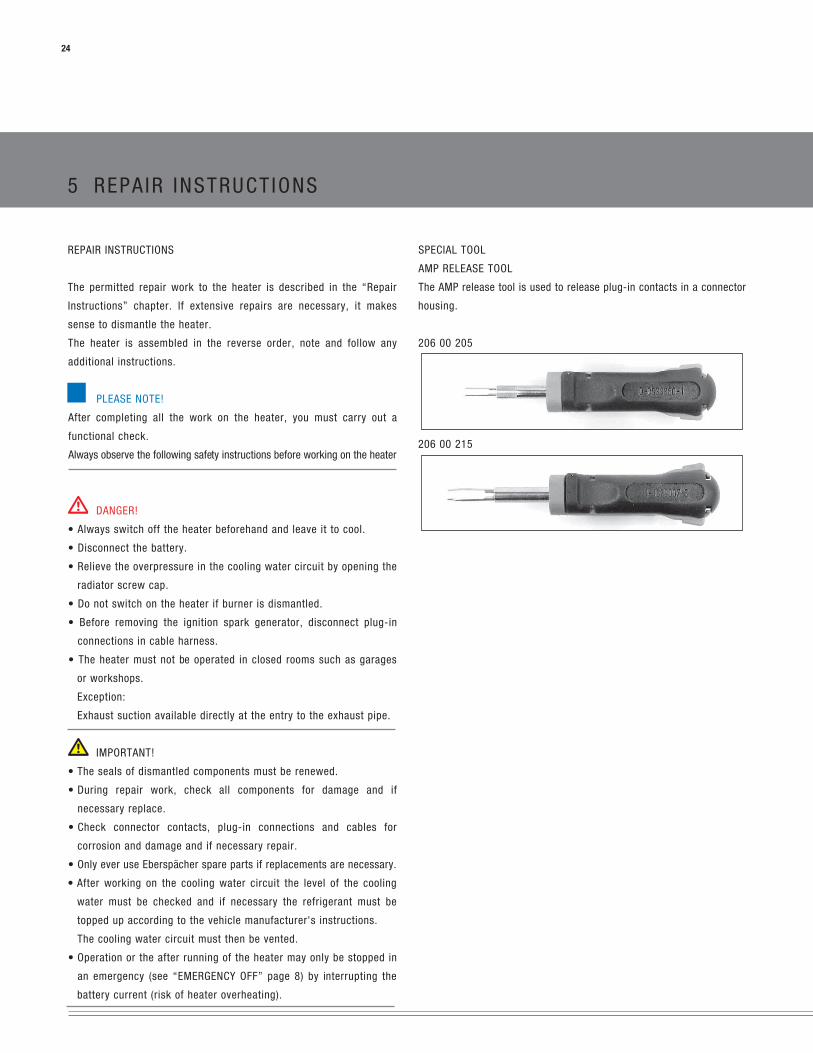
SPECIAL TOOL
AMP RELEASE TOOL
The AMP release tool is used to release plug-in contacts in a connector
housing.
206 00 205
206 00 215

5 REPA IR INSTRUCT IONS
ASSEMBLY DRAWING
25

5 REPA IR INSTRUCT IONS
26
ASSEMBLY DRAWING
COMPONENT PARTS
1 Heat exchanger 16 Baffle plate
2 Flame tube, HL2-30 / HL2-35 17 KL fuse
2a Flame tube, HL2-16 / HL2-24 18 Fuel nozzle
3 Burner 19 Fuel filter
4 Hood 20 Control box, 24 volt
5 Impeller 21 Relay
6 Grommet 22 Cable harness
7 Temperature sensor 23 Receptacle housing, 18 pin
8 Overheating sensor 24 Tab connector housing, 2-pin
9 Fuel pump (integrated in burner housing) 25 Tab connector housing, 2-pin
10 Solenoid valve 26 Receptacle housing, 8 pin
11 Electric motor, 24 volt 27 Check gauge for ignition electrode
12 Coupling 28 Seal, A10 x 13.5 DIN 7603 AL
13 Ignition spark generator, 24 volt 29 Banjo bolt
14 Ignition electrode 30 Ring connector
15 Nozzle pre-heater

5 REPA IR INSTRUCT IONS
REMOVE HOOD (see Figure 1 and 2)
• Loosen both of the hood's retaining screws.
• Remove hood.
RISK OF INJURIES!
• The impeller has sharp edges.
– Avoid touching the impeller or if necessary wear safety gloves.
REMOVE IMPELLER (see Figure 3)
• Unscrew impeller in clockwise direction, use a screwdriver to hold
the motor shaft.
PLEASE NOTE!
When assembling, tighten the impeller with 1 Nm +0.5 Nm.
27
2
2
1
12
4 5
3
12
4
3
Figure 1
1 Hood
2 Retaining screw
Figure 2
1 Hood
2 Retaining screws, burner
3 Retaining screws, hood
4 Burner
5 Heat exchanger
Figure 3
1 Impeller
2 Cable harness, heater
3 “Temperature sensor” cable loom and “overheating sensor” cable loom
4 Motor shaft (thread)
5 REPA IR INSTRUCT IONS
28
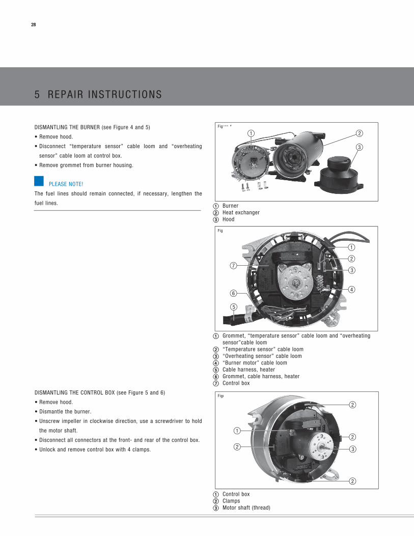
DISMANTLING THE BURNER (see Figure 4 and 5)
• Remove hood.
• Disconnect “temperature sensor” cable loom and “overheating
sensor” cable loom at control box.
• Remove grommet from burner housing.
PLEASE NOTE!
The fuel lines should remain connected, if necessary, lengthen the
fuel lines.
DISMANTLING THE CONTROL BOX (see Figure 5 and 6)
• Remove hood.
• Dismantle the burner.
• Unscrew impeller in clockwise direction, use a screwdriver to hold
the motor shaft.
• Disconnect all connectors at the front‑ and rear of the control box.
• Unlock and remove control box with 4 clamps.
Figure 4
1 Burner2 Heat exchanger3 Hood
Figure 5
1 Grommet, “temperature sensor” cable loom and “overheating
sensor”cable loom2 “Temperature sensor” cable loom3 “Overheating sensor” cable loom4 “Burner motor” cable loom5 Cable harness, heater6 Grommet, cable harness, heater7 Control box
Figure 6
1 Control box2 Clamps3 Motor shaft (thread)
1 2
3
6
7
1
2
4
3
5
2
1
2
2
3
2

5 REPA IR INSTRUCT IONS
DISMANTLING THE BURNER MOTOR (see Figure 5, 7 and 8)
• Remove hood.
• Dismantle the burner.
• Unscrew impeller in clockwise direction, use a screwdriver to hold
the motor shaft.
• If necessary, use the burner tester to test the burner motor (see below).
• Disconnect “burner motor” cable loom at control box, slot “B”.
• Undo three retaining screws of burner motor.
• Remove burner motor.
Figure 7
1 Burner motor2 Retaining screws3 Motor shaft (thread)
CHECK THE FUNCTION AND SPEED OF THE BURNER MOTOR USING THE
BURNER TESTER (see Sketch on the right side)
• Disconnect all connectors from the control box.
• Connect burner tester.
• Make a mark on the impeller.
• Keep “Heating ON” pressed for 4 seconds –> the heater starts, the
electric motor must run for 180 seconds (afterrun) –>
– if yes, measure speed using non-contact tachometer.
– if no, replace the electric motor.
SPEED OF THE ELECTRIC MOTOR
Hydronic L16 3800 ±350 rpm
Hydronic L24 4200 ±350 rpm
Hydronic L30 4800 ±350 rpm
Hydronic L35 5200 ±350 rpm
RISK OF INJURIES!
• The impeller has sharp edges.
– Avoid touching the impeller or if necessary wear safety gloves.
PLEASE NOTE!
Use the coupling, screws and plain washers included with the spare
part for the assembly.
Tighten the impeller with 1 Nm +0.5 Nm.
Figure 8
1 Burner motor2 Coupling
Sketch
1 Impeller with mark2 Burner motor
PLEASE NOTE!
• Read and follow the burner tester operating instructions.
Let the electric motor to run for 180 seconds.
29
2
2
1
3
2
2
1
21

4
3
1
2
1
1
2
Figure 9
1 Ignition electrodes
Figure 10
1 Ignition electrodes
2 Check gauge
Figure 11
1 Flame monitor
2 Baffle plate
3 Fuel nozzle
4 Ignition electrodes
5 REPA IR INSTRUCT IONS
30
DISMANTLING THE IGNITION ELECTRODES (see Figure 9 and 10)
• Remove hood.
• Dismantle the burner.
• Disconnect ignition electrodes from ignition spark generator.
PLEASE NOTE!
• If the Ignition spark generator, ignition electrodes or pump housing
is replaced it is necessary to check the distance between the
ignition electrodes with a check gauge.
The check gauge is included with the spare parts.
• Push the check gauge in the fuel nozzle and press up to the limit
stop. The electrode tips must lie against the square surfaces of the
check gauge, if not –> renew ignition electrodes.
• If the insulation body of the ignition electrodes is damaged
–> renew ignition electrodes.
• Do not touch the fuel nozzle opening when measuring the electrode
spacing.
• The check gauge is solely for checking and not for setting the
distance between the electrode tips.
• If the distance between the ignition electrodes differs from what it
should be –> renew ignition electrodes.
• Bending the ignition electrodes is not allowed.
DISMANTLING THE FUEL NOZZLE (see Figure 11)
• Remove hood.
• Dismantle the burner.
• Dismantle the ignition electrodes.
• Unscrew fuel nozzle from the nozzle block, press against the nozzle
block with wrench.
PLEASE NOTE!
• When installing the fuel nozzle do not touch the nozzle opening.
• After installing the fuel nozzle, check the position of the ignition
electrodes, renew if necessary.
• Tightening torque for fuel nozzle: 16 ±1 Nm.

4
2
1
2
3
2
1
2
5 REPA IR INSTRUCT IONS
DISMANTLE IGNITION SPARK GENERATOR (see Figure 12 – 14)
• Remove hood.
• Dismantle the burner.
• Dismantle the ignition electrodes.
• Pull fuse clip (KL fuse) off nozzle block and remove baffle plate.
• If necessary, use the burner tester to test the ignition spark generator
(see below).
• Disconnect ignition spark generator cable loom at control box, slot “E”.
• Undo both retaining screws of ignition spark generator.
• Remove ignition spark generator.
PLEASE NOTE!
• When installing insert the ignition spark generator in the burner
housing locator fixings.
• Use the screws and plain washers included with the spare part for
the assembly.
• After installing, check distance between ignition electrodes, if ne-
cessary renew ignition electrodes.
• Lay the cable harnesses as shown in Figure 8 and 9.
Figure 13
1 Ignition spark generator2 Connection of the “ignition spark generator” cable loom to the
control box, slot “E”
RISK OF INJURIES!
• A spark gap with a voltage of approx. 20 000 volt forms between the
electrodes.
– Test the ignition spark generator only using the burner tester.
– Do not test ignition spark generator without ignition electrodes.
Figure 12
1 Ignition electrodes2 Fuse clip (KL fuse)3 Baffle plate
Figure 14
1 Ignition spark generator2 Locator fixings for the ignition spark generator
FUNCTIONAL CHECK
• Disconnect all connectors from the control box.
• Connect burner tester.
• Press “ZFG” button –> a spark gap must form between the
electrodes
– if not, replace the ignition spark generator.
31
HIGH VOLTAGE!
Always note when testing the ignition spark generator!

1 2
1
5 REPA IR INSTRUCT IONS
32
DISMANTLING THE SOLENOID VALVE (see Figure 15 and 16)
• Remove hood.
• Dismantle the burner.
• Disconnect ignition electrodes from ignition spark generator.
• Unscrew fuel nozzle (3) from the nozzle pre-heater (2), at the same
time press against the nozzle pre-heater with a spanner.
Reuse the fuel nozzle.
• Pull fuse clip (KL fuse) from the nozzle pre-heater and remove
diffuser.
• Disconnect cable loom from control box, slot “F”.
• Dismantle the nozzle pre-heater. Keep the screws and spring lock
washers for reuse.
PLEASE NOTE!
When installing lay the cable looms as shown in Figure 15.
TESTING THE SOLENOID VALVE USING THE BURNER TESTER
• Disconnect all connectors from the control box.
• Connect burner tester.
• Press “MV” button –> solenoid valve must click
– if not, replace solenoid valve.
Figure 15
1 Solenoid valve2 Connecting the “solenoid valve” cable loom to the control box,
slot “D”
Figure 16
1 Solenoid valve

5 REPA IR INSTRUCT IONS
DISMANTLING THE NOZZLE PRE-HEATER (see Sketch)
• Remove hood.
• Dismantle the burner.
• Disconnect ignition electrodes from ignition spark generator.
• Unscrew fuel nozzle (3) from the nozzle pre-heater (2), at the same
time press against the nozzle pre-heater with a spanner.
Reuse the fuel nozzle.
• Pull fuse clip (KL fuse) from the nozzle pre-heater and remove
diffuser.
• Disconnect cable loom from control box, slot “F”.
• Dismantle the nozzle pre-heater. Keep the screws and spring lock
washers for reuse.
PLEASE NOTE!
• When installing the fuel nozzle do not touch the nozzle opening.
• After installing the fuel nozzle, check the position of the ignition
electrodes, renew if necessary.
Functional check of the nozzle pre-heater
• Connect ohmmeter to the 2-pin receptacle housing –> if the mea-
sured value is approx. 5 – 10 Ω the nozzle pre-heater is ok, if not,
replace the nozzle pre-heater.
INSTALLING THE NOZZLE PRE-HEATER
• Check the O-ring (1) is properly positioned and fits in the pump
housing.
• Install the nozzle pre-heater (plastic) using the screws and spring
lock washers saved for reuse, tightening torque 2 +0.5 Nm.
• Plug cable loom into control box, slot “F”.
• Install the deflector and push on fuse clip (KL fuse).
• Fit fuel nozzle (3), press down on the nozzle pre-heater with a spanner.
Tightening torque for fuel nozzle 16 ±1 Nm.
• Install ignition electrodes on ignition spark generator. Check the
position of the ignition electrodes, renew if necessary.
• Install the burner.
• Fit the hood.
Sketch
1 O-ring, pump housing2 Nozzle pre-heater3 Fuel nozzle
33
1 2 3

12
3
5 REPA IR INSTRUCT IONS
34
DISMANTLING THE FLAME TUBE (see Figure 17 and Sketch)
• Remove hood.
• Dismantle the burner.
• Remove flame tube from the heat exchanger.
PLEASE NOTE!
When installing insert the detent of the flame tube in the
groove of the heat exchanger.
Sketch
1 Flame tube2 Detent on flame tube3 Heat exchanger
Figure 17
1 Flame tube2 Detent on flame tube3 Heat exchanger
12 3

2
1
1 2
5 REPA IR INSTRUCT IONS
DISMANTLING THE TEMPERATURE SENSOR AND OVERHEATING SENSOR
(see Figure 18 and Figure 19)
• Remove hood.
• Dismantle the burner.
• Unscrew impeller in clockwise direction, use a screwdriver to hold
the motor shaft.
• Disconnect temperature and/or overheating sensor connectors at
control box.
• Unscrew temperature sensor and overheating sensor from the heat
exchanger.
PLEASE NOTE!
For temperature sensor and overheating sensor resistance values, see
page ??.
Figure 18
1 Solenoid valve2 Connecting the “solenoid valve” cable loom to the control box,
slot “D”
Figure 19
1 Solenoid valve
35

5 REPA IR INSTRUCT IONS
36
RESISTANCE VALUES FOR TEMPERATURE SENSOR AND OVER HEATING
SENSOR (see Sketches)
Test the temperature sensor and the overheating sensor using a digital
multimeter and compare the values with the diagram or the charac-
teristic values table.
If the measured values do not match the diagram or the characteristic
values table, then replace the temperature sensor or the overheating sensor.
Check for earth short:
There must be no electrical connection between the sensor connec-
tions and the housing.
Resistance value must be ∞.
Diagram – overheating sensor (section)
Characteristic values table – overheating sensor (NTC)
Temp. [°C] Resistance value [ Ω ] all. deviation [± Ω ]- 40 3 492 000 324 600
0 337 933 21 56025 103 517 5 00040 55 143 3 13060 25 950 1 72780 13 118 995
100 7 099 597120 4 069 374130 3 135 300150 1 917 199180 981 115200 668 85
Resistance [kΩ ]
Temperature [°C]
Diagram – temperature sensor (section)
Characteristic values table – temperature sensor (PTC)
Temp. [°C] Resistance value [ Ω ] all. deviation [± Ω ]- 40 567 18
0 815 1525 1000 1240 1122 1660 1299 2380 1490 30
100 1696 44120 1915 52130 2023 62
Resistance [ Ω ]
Temperature [°C]

5 REPA IR INSTRUCT IONS
DISMANTLING THE GAUZE FUEL FILTER (see Figure 20)
• Remove hood.
• Dismantle the burner.
• Unscrew the banjo bolt and the ring connector from the fuel flow line
at the burner.
• Unscrew the gauze fuel filter from the burner housing, clean or replace.
DANGER!
RISK OF FIRE, EXPLOTION AND POISONING!
Caution when handling fuel.
Avoid naked flames when handling fuel.
Do not smoke, this also applies where fuel is only noticed by
its characteristic odour.
Do not inhale fuel fumes.
When dismantling the fuel flow line, collect any escaping fuel.
PLEASE NOTE!
• The relevant rules of sound engineering practice and any informa-
tion provided by the vehicle manufacturer are to be observed during
the installation and repair.
• When carrying out electric welding on the vehicle, the positive cable
at the battery should be disconnected and placed at ground to pro-
tect the control box.
NOTES ON THE FUEL FLOW RATE AND THE PRESSURE IN THE FUEL SYSTEM
Precise checking of the fuel flow rate is not possible.
If necessary the combustion can be checked by checking the CO2 level
in the exhaust.
If it is necessary to change the combustion air set in the factor (CO2
level), this can be achieved by turning the adjusting cap (see page ??).
To ensure perfect function of the fuel pump you must ensure that the
partial vacuum in the fuel system does not become too large (see diagram).
Figure 20
1 Banjo bolt2 Seal, A10 x 13.5 DIN 7603 AL3 Ring connector d Gauze fuel filter4 Gauze fuel filter
PLEASE NOTE!
Install banjo bolt and ring connector with new seals (A10 x 13.5 DIN 7603
AL). Tightening torque of the banjo bolt 12 ± 1.2 Nm.
RELIABILITY PERFORMANCE OF THE HEATER DEPENDING ON THE UNDER-
PRESSURE (PARTIAL VACUUM) IN THE FUEL SYSTEM
In order to ensure the fuel pump works, it is necessary to ensure that the
underpressure in the fuel system is not too large (see table).
37
1 2 2 43
Fuel pressure (P) Fuel pressure (P)
Heater inlet Filter inlet
Preferred range * min. –0.3 bar min. –0.2 bar
Allowable range ** –0.45 bar to –0.3 bar –0.35 bar to –0.2 bar
Critical range *** –0.55 bar to –0.45 bar –0.45 bar to –0.35
Heating mode not possible < –0.55 bar < –0.45 bar
* Range for design of the fuel supply.
** The counterpressure in the fuel supply can increase over the operating power due to deposits (filter becomes blocked).
*** Heater becomes susceptible to faults (gas bubbles are formed / fault code 52, 54).

5 REPA IR INSTRUCT IONS
38
MEASURE CO2-LEVEL IN THE EXHAUST
DANGER!
RISK OF FIRE, EXPLOTION AND POISONING!
• The heater must not be operated in closed rooms such as garages
or workshops without an exhaust extraction system.
• Do not operate the heater if the burner is dismantled.
PLEASE NOTE!
• It is necessary to measure the CO2 level, if necessary adjust the
combustion air:
– after repairs to heater (functional check).
– if combustion is not working properly.
– after replacing the fuel nozzle.
MEASUREMENT
Measure the CO2 level of the heater in the vehicle ready for service.
In order to take a correct measurement of the CO2‑ level the heater
must have reached its operating temperature.
Measure the CO2 level using a CO2 indicator, to this end, read and
follow the manufacturer's instructions.
ADJUSTING THE COMBUSTION AIR (see Figure 21)
• Undo the adjusting cap screws.
– If the CO2 level is less than 9 % by vol, turn the adjusting cap to
the left (CO2 +).
– If the CO2 level is higher than 11 % by vol, turn the adjusting cap
to the right (CO2 –).
• Retighten the adjusting cap.
• If proper adjustment of the CO2 level is no longer possible:
– Check the burner for damage.
– Check the speed of the electric motor.
– Replace fuel nozzle.
Figure 21
1 Adjusting cap
1

5 REPA IR INSTRUCT IONS
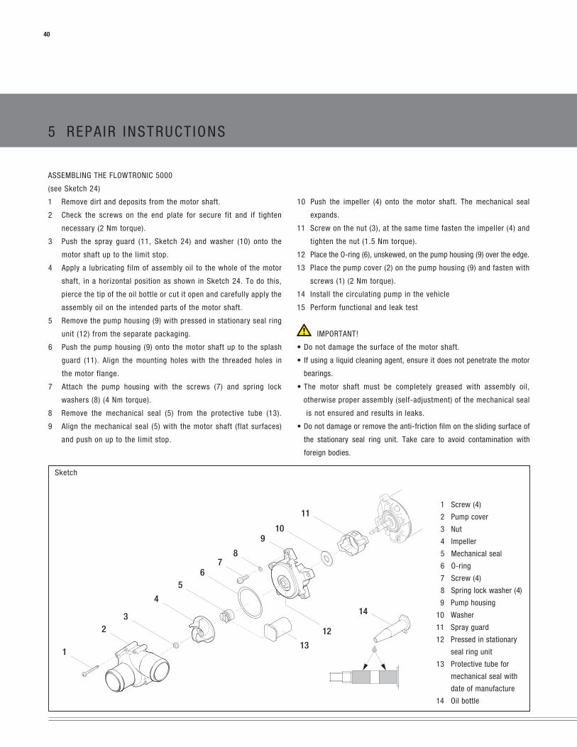
DISMANTLING THE FLOWTRONIC 5000
(see Sketch 23)
1. Remove the screws (1) on the pump cover (2).
2. Remove the pump cover (2) and check for damage.
3. Undo the nut (3) while holding on to the impeller (4), unscrew from
the motor shaft and dispose of the nut.
4. Pull the impeller (4) off the motor shaft and throw away.
5. Undo and dispose of the screws (7) with spring lock washers (8)
on the pump housing (9).
6. Pull the pump housing (9) with mechanical seal (5) and stationary
seal ring (12) and O-ring (6) from the motor shaft and throw away.
7. Remove the washer (10) and if necessary the spray guard (11) off
the motor shaft and throw away.
8. Check motor for smooth and easy movement and examine for
damage, unbalance and noise generation.
Sketch
PLEASE NOTE!
• The Flowtronic 5000 spare parts kit
(Order No.: 25 1818 99 29 10) contains a new mechanical steel
which requires particular care to install. The mechanical seal may
only be replaced together with the replacement of the complete seal kit.
• Before using the Flowtronic 5000 spare parts kit (Order No.:
25 1818 99 29 10), check to ensure the maximum shelf life of the
mechanical seal (printout on the protective covering + 4 years) has
not been exceeded.
1 Screw (4)
2 Pump cover
3 Nut
4 Impeller
5 Mechanical seal
6 O-ring
7 Screw (4)
8 Spring lock washer (4)
9 Pump housing
10 Washer
11 Spray guard
12 Stationary seal ring
39
5 REPA IR INSTRUCT IONS
40
ASSEMBLING THE FLOWTRONIC 5000
(see Sketch 24)
1 Remove dirt and deposits from the motor shaft.
2 Check the screws on the end plate for secure fit and if tighten
necessary (2 Nm torque).
3 Push the spray guard (11, Sketch 24) and washer (10) onto the
motor shaft up to the limit stop.
4 Apply a lubricating film of assembly oil to the whole of the motor
shaft, in a horizontal position as shown in Sketch 24. To do this,
pierce the tip of the oil bottle or cut it open and carefully apply the
assembly oil on the intended parts of the motor shaft.
5 Remove the pump housing (9) with pressed in stationary seal ring
unit (12) from the separate packaging.
6 Push the pump housing (9) onto the motor shaft up to the splash
guard (11). Align the mounting holes with the threaded holes in
the motor flange.
7 Attach the pump housing with the screws (7) and spring lock
washers (8) (4 Nm torque).
8 Remove the mechanical seal (5) from the protective tube (13).
9 Align the mechanical seal (5) with the motor shaft (flat surfaces)
and push on up to the limit stop.
Sketch
10 Push the impeller (4) onto the motor shaft. The mechanical seal
expands.
11 Screw on the nut (3), at the same time fasten the impeller (4) and
tighten the nut (1.5 Nm torque).
12 Place the O-ring (6), unskewed, on the pump housing (9) over the edge.
13 Place the pump cover (2) on the pump housing (9) and fasten with
screws (1) (2 Nm torque).
14 Install the circulating pump in the vehicle
15 Perform functional and leak test
IMPORTANT!
• Do not damage the surface of the motor shaft.
• If using a liquid cleaning agent, ensure it does not penetrate the motor
bearings.
• The motor shaft must be completely greased with assembly oil,
otherwise proper assembly (self-adjustment) of the mechanical seal
is not ensured and results in leaks.
• Do not damage or remove the anti-friction film on the sliding surface of
the stationary seal ring unit. Take care to avoid contamination with
foreign bodies.
1 Screw (4)
2 Pump cover
3 Nut
4 Impeller
5 Mechanical seal
6 O-ring
7 Screw (4)
8 Spring lock washer (4)
9 Pump housing
10 Washer
11 Spray guard
12 Pressed in stationary
seal ring unit
13 Protective tube for
mechanical seal with
date of manufacture
14 Oil bottle

12
34
56
7
89
10
5 REPA IR INSTRUCT IONS
DISMANTLING THE FLOWTRONIC 6000 S / 6000 SC
(see Sketch 25)
1 Remove 4 screws (10) in pump cover.
2 Remove pump cover, clean, examine for leaks and damage and
throw away O-ring (1).
3 Undo the nut (2) while holding onto the impeller (5), remove from the
shell shaft and dispose of.
4 Pull off the support ring (3) and impeller with inner rotor and thrust
ring (4) from the shell shaft and throw away.
5 Remove screws (5) and spring lock washers (6) from the shell (7).
PLEASE NOTE!
The tight fit of the centring ring on the inside of the shell (7) makes
pulling off difficult. In addition, the magnetic forces of the coupling
must be overcome when pulling off. The centring ring remains hang-
ing onto the outer rotor.
6 Remove the shell (7) with diaphragm (8) by pulling it axially off the
motor flange and throw away together with O-ring (3).
7 Remove flat seal (9) from motor and throw away.
8 Carefully remove dirt and deposits from the outer rotor.
9 Check motor for smooth and easy movement and, together with the
outer rotor, check for damage, unbalance and noise and if neces-
sary throw away.
Sketch
IMPORTANT!
The specified order must be adhered to when dismantling or
assembling. It is important for the pump to be completely dismantled
as described to enable any interior damage to be identified and
repaired.
Ensure that no small particles or parts enter the body of the pump
through the water inlet and outlet connections.
PLEASE NOTE!
• The magnets on the inside of the outer rotor are fragile and can be
torn off the adhesive point if excessive forces are applied. If using a
cleaning agent, prevent liquid from getting inside the motor. Signs
of flash rust on the outer rotor of the dismantled pump are normal.
Flash rust is not an indication that the outer rotor no longer fulfils its
function – transfer or torque from motor shaft to pump impeller.
1 O-ring
2 Nut
3 Support ring
4 Impeller with inner rotor and thrust ring
5 Screw (3)
6 Spring lock washer (3)
7 Shell
8 Diaphragm
9 Flat seal
10 Screw (4), not included in scope of supply
41

5 REPA IR INSTRUCT IONS
42
ASSEMBLING THE FLOWTRONIC 6000 S / 6000 SC
(see Sketch 25)
1 Firmly push the centring ring onto the collar of the motor flange and
at the same time centre it.
2 Place the new shell (8) on the outer motor, centre on the centring
ring and fix onto the motor flange using the new screws and new
spring lock washers.
3 Carefully push the new impeller with inner rotor (5) onto the shell
shaft.
4 Mount the new thrust ring (4), new support ring (3) and new nut (2)
onto the shell shaft while holding onto the impeller (5).
5 Place the new O-ring (1) over the edge of the shell (8) free of twist.
6 Place the pump cover on the shell (8) and fix with 4 screws (9).
7 Install the circulating pump in accordance with the appropriate
installation instructions.
8 Perform leak and functional test.
The tightening values (torques) of the fixing elements are given in the
table below and must be precisely adhered to during assembly.
Tightening values
Item Name Nm.
2 Nut 1.4 ±10 %
6 Screw 3.5 ±10 %
9 Screw 2.0 ±10 %
IMPORTANT!
A slight magnetic stray field exists in the impeller components with
inner rotor (5) and the outer rotor when they are dismantled. When
dismantling and assembling, ensure that no small ferromagnetic parts
are lying about loose in the immediate vicinity of the installation area.
These could be attracted by the magnetic systems of the impeller with
inner rotor (5) and the outer rotor and block assembly or running of
the motor.
PLEASE NOTE!
Due to the magnetic forces in the shell (8), do not install with mounted
impeller (5) but one after the other. The magnetic coupling between
the impeller with inner rotor (5) and outer rotor causes accelerated
merging of the components. When pushing them on, ensure that the
plain bearing between the impeller with inner rotor (5) and shell (8) is
not damaged.
The tightening values (torques) of the fixing elements are given in the
table below and must be precisely adhered to during assembly.

NOTES :
43

Espar Products, Inc.
(800) 387-4800
(905) 670-0960
(905) 670-0728 Fax
www.espar.com 01.2
012
Subj
ect t
o ch
ange
with
out n
otifi
catio
n
Espar