hydronic heating specialties - amazon s3 · with watts hydronic products, you get longer valve...
TRANSCRIPT

A
Hydronic Heating Specialties
w a t t s . c o m

2

With Watts hydronic products, you get longer valve life, economical control of heating and cooling zones, energy savings for your customers and fewer callbacks. Watts products control and protect hydronic systems and your reputation. No one else offers Watts quality and design.
Table of ContentsHydronic Product Diagram - - - - - - - 2Feed Water Pressure Regulators and Dual Controls
911, 911S - - - - - - - - - - - - - - - - - - - 5 1156F - - - - - - - - - - - - - - - - - - - - - - 4 1450F - - - - - - - - - - - - - - - - - - - - - - 5 N256, T156B - - - - - - - - - - - - - - - - - 4 T145B - - - - - - - - - - - - - - - - - - - - - - 5
Backflow Preventers9D - - - - - - - - - - - - - - - - - - - - - - - - - 6 909 - - - - - - - - - - - - - - - - - - - - - - - - 7919 - - - - - - - - - - - - - - - - - - - - - - - - 8
Safety Relief Valves3L - - - - - - - - - - - - - - - - - - - - - - - - 10 53L - - - - - - - - - - - - - - - - - - - - - - - 10 174A, 374A - - - - - - - - - - - - - - - - - - - 9 315 -M1, 415 -M1 - - - - - - - - - - - - - - 11 740 - - - - - - - - - - - - - - - - - - - - - - - - 9 Fig. 31, 41, 41A - - - - - - - - - - - - - - - 10
Automatic Air Vent ValvesDuoVent - - - - - - - - - - - - - - - - - - - - 12 FV -4M1 - - - - - - - - - - - - - - - - - - - - 11 HAV - - - - - - - - - - - - - - - - - - - - - - - 12
Air SeparatorsAS - - - - - - - - - - - - - - - - - - - - - - - - 13 AS -B - - - - - - - - - - - - - - - - - - - - - - 13 AS -T - - - - - - - - - - - - - - - - - - - - - - 13 AS -MB - - - - - - - - - - - - - - - - - - - - - 12
Service Check ValveSCV - - - - - - - - - - - - - - - - - - - - - - - 15
Flow Check2000, 2000S - - - - - - - - - - - - - - - - - 15
Expansion TanksETX -ASF - - - - - - - - - - - - - - - - - - - 19ET -RA 35 – ET -RA 2000 - - - - - - - - - 18 ETX, ETSX - - - - - - - - - - - - - - - - - - 19 ETA 15 – ETA 240 - - - - - - - - - - - - - 17 HP -BHM - - - - - - - - - - - - - - - - - - - 16HP -30Pro - - - - - - - - - - - - - - - - - - - 16HPX - - - - - - - - - - - - - - - - - - - - - - - 16
Purge and Balancing ValvesRPV - - - - - - - - - - - - - - - - - - - - - - - 21
Isolation Pump Flanges IPF - - - - - - - - - - - - - - - - - - - - - - - 22 P IPF - - - - - - - - - - - - - - - - - - - - - - 23 PIPFM1 - - - - - - - - - - - - - - - - - - - - 24
Thermostatic Mixing Valves1170 -M2, L1170 -M2 - - - - - - - - - - - 25 N170 -M3 - - - - - - - - - - - - - - - - - - - 26
Hot Water Extender Tempering Valves70A, L70A - - - - - - - - - - - - - - - - - - 26
Multi-Orifice Flow Control ValveP3 - - - - - - - - - - - - - - - - - - - - - - - - 26
Flow Measurement, Balancing ValvesCSM -61 -M1 - - - - - - - - - - - - - - - - - 27 CSM -81 -F - - - - - - - - - - - - - - - - - - 28 CSM -91 - - - - - - - - - - - - - - - - - - - - 29 HBV - - - - - - - - - - - - - - - - - - - - - - 28
Low Water CutoffsN50 - - - - - - - - - - - - - - - - - - - - - - - 30SAN50, SAN89 - - - - - - - - - - - - - - - 30
Hydronic SpecialtiesCheck Valves CVY, CVYS - - - - - - - - - - - - - - - - - - 31 600 - - - - - - - - - - - - - - - - - - - - - - - 31Angle Valves, Elbows HWA - - - - - - - - - - - - - - - - - - - - - - 31 OTV -m1 - - - - - - - - - - - - - - - - - - - - 32 UL -1, UL -2 - - - - - - - - - - - - - - - - - - 31Boiler Fill Fitting RBFF - - - - - - - - - - - - - - - - - - - - - - 32Boiler Drains BD - - - - - - - - - - - - - - - - - - - - - - - 33 BD -QT - - - - - - - - - - - - - - - - - - - - - 33Gas Ball Valves GBV - - - - - - - - - - - - - - - - - - - - - - 34 GBV -1 - - - - - - - - - - - - - - - - - - - - - 34
Ball Valves B6000, B6001 - - - - - - - - - - - - - - - - 35 FBV - - - - - - - - - - - - - - - - - - - - - - - 36 FBV -3C, FBVS -3C - - - - - - - - - - - - - 37 FBV -4, FBVS -4 - - - - - - - - - - - - - - - 38Gate and Glove Valves GV, GVS, GLV - - - - - - - - - - - - - - - - 39Electric Motor Valves EMVII -6400SS - - - - - - - - - - - - - - - - 39Test Plugs TP - - - - - - - - - - - - - - - - - - - - - - - - 40Pressure Gauges DPG1 - - - - - - - - - - - - - - - - - - - - - 41 DPG3 - - - - - - - - - - - - - - - - - - - - - 42 DPG5 - - - - - - - - - - - - - - - - - - - - - 43Combinations Pressure / Temperature Gauges DPTG1, DPTG3, DPTGSA, DPTG 3L - 44Bimetal Thermometers TBR, TB - - - - - - - - - - - - - - - - - - - - 45 TBP, TBC - - - - - - - - - - - - - - - - - - - 46Liquid Fill Thermometers TA - - - - - - - - - - - - - - - - - - - - - - - - 47 TL - - - - - - - - - - - - - - - - - - - - - - - - 47Flow Switches FS10 -C - - - - - - - - - - - - - - - - - - - - 48 FS20 - - - - - - - - - - - - - - - - - - - - - - 48Strainers 77SM1 - - - - - - - - - - - - - - - - - - - - - 49 777S, S777, 777, S777S - - - - - - - - - 49
Featured Products
PIPFM1
ETX, ETSX
Designed to isolate circulator pumps to facilitate circu-lator pump replacement or repairs while integral purge port facilitates system purging.
See Page 24.
New pressurized expansion tanks. For use with heating and cooling systems.
See Page 19.
Watts Quality Sets the Standard in Hydronics
A Member of:
1

2
Watts Hydronic Heating Specialties
* Valves such as the 70A, the N170 -M2 and the ASSE 1017 -listed 1170 -M2 are for point -of -source applications as shown. ASSE 1016 -listed valves such as Watts L111, MMV -M1, or USG should be used at point -of -delivery. Note: Product information is subject to change without notice and supersedes all previous publications.
16 17
19
20
1
6
4a
3
5
*10
8
12
15 2
4
13
918
14
7
7
1111
22
15
22
2222
21
1 AS, AS -T, AS -B or AS -MB Air Separators - - 10, 11
2 9D Backflow Preventer - - - - - - - - - - - - - - - - - - - 5
3 BD, BD -QT, SW, SS Boiler Drain Valve - - - - - - - 28
4 1156F -A, 1156F, SB1156F, B1156F, N256, 1450F, T145B Boiler Fill Valve - - - - - - - - - - - - 3 -4
4a 911S: Combines S1156F Fill Valve (4) and 9D Backflow Preventer (2) - - - - - - - - - - - - - - 4 -5
5 CV, CVY Bronze Check Valve - - - - - - - - - - - - - 26
6 ETX, ETSX Expansion Tank - - - - - - - - - - - - - 13 -15
7 2000, 2000S Flow Checks - - - - - - - - - - - - - - - 12
8 P3 Flow Control Valve - - - - - - - - - - - - - - - - - - 21
9 GVS, GV Gate or GLV Globe Valve - - - - - - - - - - 34
*10 1170 -M2, 70A or N170 -M3 Mixing Valve - - - - - - 20
11 RPV Purge Valve - - - - - - - - - - - - - - - - - - - - - 17
12 3L, 53L Pressure Relief Valve - - - - - - - - - - - - - - 8
13 374A, 174A, 740 Hot Water Boiler Safety Relief Valve - - - - - - - - - - - - - - - - - - - - - - - - - - 7
14 TP Test Plug - - - - - - - - - - - - - - - - - - - - - - - - 35
15 B6000 Ball Valve, FBV -3C Series Ball Valve - 30, 33
16 DuoVent Automatic Float Vent Valve or - - - - - - - - 9
17 FV -4M1 Float Vent - - - - - - - - - - - - - - - - - - - - - 9
18 U5B -Z3, 25AUB -Z3 Water Pressure Reducing Valve
19 SCV 1⁄8" or 1⁄4" Service Check Valve - - - - - - - - - 12
20 SCV 1⁄2" Service Check Valve - - - - - - - - - - - - - 12
21 DPTG -3 Combination Temperature & Pressure Gauge - - - - - - - - - - - - - - - - - - - - - 39
22 IPF, PIPF Isolation Pump Flange - - - - - - - - - 18 -19

3
Feed Water Regulators & Dual Controls
Purge LeverAll 1⁄2" (15 mm) models furnished with a
“purge” lever to manually force the valve open for efficient system purging.
CapacityExceptionally high capacity;
far greater than any other feed valve on the market.
High Capacity Feed Water Regulators and Dual Control UnitsSpeed filling, flushes sys tem and accelerates air purgingWatts feed water pressure regulators and dual controls are offered in a choice of bronze and iron bodies with threaded, union solder or union threaded con nec tions and are standardly equipped with a fast fill purge feature. All are pro vid ed with a tight seating check member and stainless steel mesh strainer. They are also sup plied in combi -nation with a diaphragm op er at ed pressure relief valve where dual control service is desired.
High CapacityStandardly furnished with a “purge lever” which is only needed for “purging” be cause of the high capacity feeding ability of Watts feed water pressure reg u la tors. Watts has higher feeding capacity than most competitive models.
Exceptional Design
S1156F furnished with union solder con-nection for easy installation. Other models available with union threaded, union fittings or threaded inlet connection.
Used to fill the boiler and system piping with water and to maintain water pressure in the system at all times. Feed water pressure regulators are also used to provide make up water to the system in the event of system leaks. The fast fill feature is used for speed filling and purging of air from the piping on the initial fill. Dual control units combine the fill valve with a safety pressure relief valve.
System Purging Ability with Various Supply Pressures and Valve Wide Open
lpm gpm 53 14
45 12
38 10
30 8
23 6
15 4
8 2
0 00 10 20 30 40 50 60 70 80 psi0 69 138 207 276 345 413 482 551 kPa
Flow
gpm
/ lp
m —
Wat
er
Inlet or Supply Pressure — psi / kPaOnce the system is pressurized, the purge lever
is then utilized for purging the system.
Choice of Inlet ConnectionsFurnished with either threaded, union solder or union threaded connections.Also furnished with non-union threaded inlet connection for lower cost.
StrainerAll models provided with stainless steel
strainer to protect valve disc from fouling.
Tight Seating Check FeatureAll regulators furnished with tight seating check valve feature.
S1156F

4
Feed Water Regulators & Dual Controls
S1156F
MOdEL SIzE(dN) dIMENSIONS WEIghT
A B in. mm in. mm in. mm lbs. kgs.
1156F 1⁄2 15 31⁄2 89 53⁄8 137 2.1 .951156F-A 1⁄2 15 31⁄2 89 53⁄4 146 2.1 .95T1156F 1⁄2 15 41⁄4 108 53⁄8 137 2.2 1S1156F 1⁄2 15 41⁄8 105 53⁄8 137 2.3 1B1156F* 1⁄2 15 31⁄2 89 53⁄8 137 2.1 1SB1156F* 1⁄2 15 43⁄8 111 53⁄8 137 2.2 1TB1156F* 1⁄2 15 41⁄8 105 53⁄8 137 2.3 1*Bronze Body
A
B
Models N256, T156BFeed Water Pressure Regulator Bronze Body
MOdEL SIzE (dN) dIMENSIONS WEIghT
A B C in. mm in. mm in. mm in. mm lbs. kgs.
Regulator and strainer
T156B* 1⁄2 15 55⁄16 135 63⁄16 157 15⁄8 41 2.5 1.1 N256* 3⁄4 20 63⁄8 162 4 102 13⁄8 35 3.5 1.6*Bronze Body
A
B
C
B
A
C
N256 T156B
Sizes: 1⁄2" and 3⁄4" (15 and 20mm)Model N256 has tight seating check valve with integral strain er and unit ized design for sim pli fied servicing. Set at 15psi (103.4 kPa).
T156B has separate strain er.
Pressure - TemperatureMaximum Tem per a ture: 212°F (100°C) Maximum pressure: 100psi (6.9 bar)
Dimensions — Weights
Dimensions — Weights
Size: 1⁄2" (15mm)Model S1156F features highest purging capacity furnished with union solder inlet connection performance as well as simplified servicing.
Pressure - TemperatureMaximum working pressure: 100psi (6.9 bar) Maximum temperature: 212°F (100°C) Adjustment range: 10 – 25psi (68.7 – 172.4 kPa) Set at 15psi (103.4 kPa)
Models1156F - Identical to the above except it is furnished with threaded inlet con nec tion.
SB1156F - Identical to S1156F except it has a bronze body.
T1156F, TB1156F - Identical to the above except it is furnished with union threaded inlet con nec tion.
1156F-A - Identical to the above except it is furnished with 1⁄2" female bottom connection for installation of expansion tank.
B1156F - Bronze valve body with threaded inlet connection.
Series 1156FFeed Water Pressure Reg u la tors Iron or Bronze Body

5
Feed Water Regulators & Dual Controls
Series 1450FIron Body Dual ControlSize: 1⁄2" (15 mm)Combines construction features of Model 1156F and rug ged iron body diaphragm relief valve, set at 30psi (206.9 kPa).
Pressure - TemperatureMaximum Working Pressure: 100psi (6.9 bar)
Maximum Temperature: 212°F (100°C)
ModelsT1450F – Identical to above except fur nished with union thread ed inlet con nec tion.
S1450F – Identical to above except fur nished with union solder inlet con nec tion.
Model T145BBronze Body Dual ControlSize: 1⁄2" (15 mm)All bronze dual control consisting of feed water regulator, 30psi (206.9 kPa) diaphragm relief valve and bronze strainer designed to fill the boiler and system piping with water and to maintain water pres -sure in the system at all times. These valves also provide make up water to the system in the event of system leaks.
Pressure - TemperatureMaximum Temperature: 212°F (100°C) Maximum Pressure: 100psi (6.9 bar)
Series 911, 911SCombination Fill Valve and Backflow Preventer for Hot Water BoilersSize: 1⁄2" (15mm)Model 9D Backflow Preventer and Model 1156F Feed Water Pressure Regulator in one pre -as sem bled unit. Used on boiler feed lines to provide make -up water to the boiler and pre -vent backflow when supply pressure falls below system pressure.
Features• Pre-assembledforeaseofinstallation• Easyserviceaccessibility• Highcapacityfillvalveforquick
system filling and purging
Options: Suffix:
S – 1⁄2" (15mm) union solder inlet x 1⁄2" (15mm) threaded outlet
Prefix: B – bronze body regulator
Pressure - TemperatureMaximum Pressure: 100psi (6.9 bar) Maximum Temperature: 212°F (100°C)
Boiler fill valve set at 15psi (103.4 kPa) Adjustable range 10 – 25psi (68.9 – 172.4 kPa
Models911 – NPT x NPT connections911S – solder x NPT connectionsB911 – all bronze constructionB911S – all bronze construction union solder x NPT connections
MOdEL SIzE (dN) dIMENSIONS WEIghT
A B in. mm in. mm in. mm lbs. kgs.
911 1⁄2 15 81⁄2 216 51⁄4 133 4.2 1.9911S 1⁄2 15 81⁄2 216 51⁄4 133 4.2 1.9B911 1⁄2 15 81⁄2 216 51⁄4 133 4.2 1.9B911S 1⁄2 15 81⁄2 216 51⁄4 133 4.2 1.9
MOdEL SIzE (dN) dIMENSIONS WEIghT
A B C in. mm in. mm in. mm in. mm lbs. kgs.
Dual Controls - regulator and relief valve
1450F 1⁄2 15 55⁄16 135 61⁄2 165 15⁄8 41 3.3 1.5 T1450F 1⁄2 15 55⁄16 135 71⁄4 184 15⁄8 41 3.3 1.5 S1450F 1⁄2 15 55⁄16 135 7 178 15⁄8 41 3.3 1.5Strainer, regulator and relief valve
T145B 1⁄2 15 55⁄16 135 81⁄2 216 15⁄8 41 3.5 1.6
A
B
C
B
A
1450F
C
B
A
T145B
911
Dimensions — Weights
Dimensions — Weights

6
Backflow Preventers
MOdEL SIzE (dN) dIMENSIONS WEIghT
A B C D in. mm in. mm in. mm in. mm in. mm lbs. kgs.
9D-M3 1⁄2 15 415⁄16 110 217⁄32 64 29⁄16 65 129⁄32 48 11⁄2 .7 9DS-M3 1⁄2 15 43⁄8 111 217⁄32 64 217⁄32 64 127⁄32 50 11⁄2 .7 9D-M2 3⁄4 20 415⁄16 110 215⁄32 63 29⁄16 65 129⁄32 48 13⁄4 .8 9D-S M2 3⁄4 20 413⁄16 122 215⁄32 63 23⁄4 70 21⁄16 52 13⁄4 .8
Used on boiler feed lines to prevent boiler water from returning to the potable water system. Boiler water may contain chemicals and bacteria that could contaminate the potable water system.
Series 9DDual Check Valve with Intermediate Atmospheric VentSizes: 1⁄2" and 3⁄4" (15 and 20mm)
A
B
C d
9dEspecially made for smaller supply lines. It is typically installed on boiler feed lines to prevent backflow caused by backsiphonage or backpressure. For systems without antifreeze, rust inhibitors or other chemicals. Brass body with stainless steel working parts, integral strainer and durable rubber discs.
Pressure - TemperatureMaximum Working Pressure: 175psi (12.1 bar)
Minimum Required Pressure: 25psi (172 kPa)
Maximum Temperature: 180°F (82°C) sustained, 250°F (121°C) intermittent
Models9D – sizes 1⁄2" (15mm), 3⁄4" (20mm) NPT female union inlet and outlet con nec -tions.
9DS – sizes 1⁄2" (15mm), 3⁄4" (20mm) with union end solder connections.
9D-SC – with satin chrome fin ish.
9DS-SC – with satin chrome fin ish.
Approvals
Tested and certified under ASSE Standard 1012 and CSA Standard B64.3.
For additional information, request literature ES-9DM3/M2.
Dimensions — Weights

7
Backflow Preventers
MOdEL SIzE (dN) dIMENSIONS WEIghT
A B C D L M N in. mm in. mm in. mm in. mm in. mm in. mm in. mm in. mm lbs. kgs.
909QT 3⁄4 20 143⁄8 365 83⁄4 222 4 102 43⁄4 121 71⁄2 191 – – – – 14 6.3 909QT 1 25 153⁄8 391 83⁄4 222 4 102 43⁄4 121 71⁄2 191 – – – – 15 6.8 909M1QT 11⁄4 32 181⁄2 470 12 305 51⁄2 140 61⁄2 165 12 305 – – – – 40 18.0 909M1QT 11⁄2 40 19 483 12 305 51⁄2 140 61⁄2 165 12 305 – – – – 40 18.0 909M1QT 2 50 191⁄2 495 12 305 51⁄2 140 61⁄2 165 121⁄4 311 – – – – 40 18.0 909QT-S 3⁄4 20 143⁄8 365 83⁄4 222 4 102 43⁄4 121 71⁄2 191 33⁄16 81 23⁄4 70 155⁄8 7.1 909QT-S 1 25 153⁄8 391 83⁄4 222 4 102 43⁄4 121 71⁄2 191 33⁄4 95 3 76 171⁄2 7.9 909M1QT-S 11⁄4 32 181⁄2 470 115⁄8 295 51⁄2 140 61⁄2 165 12 305 47⁄16 113 31⁄2 89 423⁄4 19.4 909M1QT-S 11⁄2 40 19 483 115⁄8 295 51⁄2 140 61⁄2 165 12 305 47⁄8 124 4 102 44 20.0 909M1QT-S 2 50 191⁄2 495 115⁄8 295 51⁄2 140 61⁄2 165 121⁄4 311 515⁄16 151 5 127 473⁄8 21.5
Series 909Reduced Pressure Zone AssembliesSizes: 3⁄4" – 2" (20 – 50mm)Provides protection against backpressure or backsiphonage backflow in larger systems or those with chemical additives. Unique de sign of “air -in/wa ter -out” principle provides high ca pac i ty relief valve dis charge per for -mance during the emer gen cy conditions of com bined backsi pho n age and backpressure with both checks fouled. Series 909QT is standardly fur nished with NPT con nec tions and quar ter -turn, full port re sil ient seated bronze ball valves, 3⁄4" and 1" (20 and 25mm) have tee handle shutoffs.
Supply pressures up to 175psi (12.06 bar) and water temperatures to 140°F (60°C). Sizes 3⁄4" and 1" (20 and 25mm) have female threaded body NPT connections. Sizes 11⁄4" – 2" (32 – 50mm) have male threaded body NPT connections.
Features• Bronzebodyconnection• Replaceableseats• Ballvalvetestcocks• Nospecialtoolsrequiredforservicing• Modulardesign
Note: The installation of a drain line is recommended. When installing a drain line, an air gap is necessary.
Options can be combined Suffix:
S - bronze strainer HW - stainless steel check modules for hot and harsh water conditions to 210°F (99°C) LF - without shutoff valves PC - Internal polymer coating
Prefix:
U - 3⁄4" and 1" (20 and 25mm) union connections FAE - 11⁄4" – 2" (32 – 50mm) flanged adapter ends
For additional information, request literature ES-909S.
A
C
d
B
L
M
N
909QT-S
909
Dimensions — Weights
Pressure — TemperatureMaximum Working Pressure: 175psi (12.1 bar)
Temperature Range: 33°F – 140°F (0.5°C – 60°C) continuous, 180°F (82°C) intermittent

8
Backflow Preventers
Series 919Reduced Pressure Zone AssembliesSizes: 1⁄4" – 2" (5 – 50mm)
Features• Separateaccesscoversforthecheckvalvesandreliefvalvefor
ease of maintenance• Topentry-allcheckinternalseasilyaccessible• Allrubberelastomersofchloramineresistantmaterial• Checkvalvepoppetassembliesarefullyguidedbyinnovative
plastic seat guide• Replaceablepush-incheckvalveandreliefvalveseats
eliminates threads from the water way• EZtwistreliefvalvecover-quarterturnlockingjointcaptures
the spring load during repair to facilitate disassembly• Innovativecheckvalveplasticcoverbushingprovidestrouble
free guiding of the check valve poppet• Bottommountedreliefvalveprovidesreducedinstallation
clearances• Compact,spacesavingdesign• Nospecialtoolsrequiredforservicing• Topmountedtestcocksforeaseintestingandreduced
installation clearances• StandardlyfurnishedwithNPTbodyconnections
Pressure — TemperatureTemperature Range: 33ºF – 180ºF (0.5ºC – 82ºC)
Maximum Working Pressure: 175psi (12.1 bar)
Dimensions — Weights
F
A
N
d
E g h
M B
C
919
Series 919 Reduced Pressure Zone Backflow Assemblies are de -signed to protect potable water supplies in accordance with national plumbing codes and water authority requirements. This series can be used in a variety of installations, including the prevention of health hazard cross -connections or for containment at the service line entrance.
This series features two poppet style check valves, replaceable check seats, with an intermediate relief valve. Its compact modular design facilitates easy maintenance and assembly access. Sizes 1⁄4" – 1" (5 – 25mm) shutoffs have tee handles.
OptionsSuffix:
QT – quarter -turn ball valves
S – bronze strainer
LF – without shutoff valves
AQT – elbow fitting for 360º rotation
ZQT – inlet & outlet flow up
Prefix:
U – union connections
SIzE (dN) dIMENSIONS STrAINEr dIMENSIONS WEIghT
A B C D E (LF) F G H M N 919QT 919QT-S
in. mm in. mm in. mm in. mm in. mm in. mm in. mm in. mm in. mm in. mm in. mm lbs. kgs. lbs. kgs. 1/4 8 91/2 241 67/8 175 27/8 73 123/8 314 53/4 146 3 75 13/8 35 19/16 40 23/8 60 21/2 64 5.8 2.6 6.3 2.9
3/8 10 91/2 241 67/8 175 27/8 73 123/8 314 53/4 146 31/3 84 13/4 44 19/16 40 23/8 60 21/2 64 5.8 2.6 6.3 2.9 1/2 15 91/2 241 67/8 175 27/8 73 123/4 324 53/4 146 33/8 86 17/8 48 19/16 40 23/4 70 21/4 57 5.8 2.6 6.3 2.9
3/4 20 121/8 307 77/16 188 31/2 88 151/2 393 711/16 195 35/8 92 21/16 52 19/16 40 15/8 41 33/16 81 8.3 3.7 10.0 4.5
1 25 141/2 368 8 202 37/8 98 193/16 487 93/16 233 4 102 27/16 62 19/16 40 21/8 54 33/4 95 11.8 5.4 13.8 6.3
11/4 32 181/8 461 117/16 290 51/8 129 231/4 591 1111/16 297 51/8 130 25/8 67 21/2 64 21/2 64 47/16 113 22.3 10.1 26.3 11.9
11/2 40 183/4 476 117/16 290 51/8 129 251/16 637 1111/16 297 55/8 143 31/8 79 21/2 64 3 76 47/8 124 28.3 12.8 32.0 14.5
2 50 211/16 535 121/16 307 55/8 142 2813/16 732 133/8 340 515/16 151 37/16 87 21/2 64 39/16 90 515/16 151 37.3 16.9 45.0 20.4

9
The safety relief valve is mounted directly to the boiler to prevent excess pressure buildup in the boiler. The capacity of the relief valve must be greater than the BTU input of the boiler.
Sizes: 3⁄4" – 2" (20 – 50mm)Iron body safety relief valves with ex pand ed out lets for hot water space heating boilers. Pres sure range 30 – 75psi (206.9 – 517.1 kPa) with cor re spond ing high rat ings from 925,000 – 10,700,000 BTU/Hr. A wide range of re lief capacities. Lower BTU per thou sand cost because this se ries pro vides a much high er BTU rating and size for size than other valves on the market. Fe male inlet and out let con nec tions.
MOdEL SIzE (dN) dIMENSIONS WEIghT
A B in. mm in. mm in. mm lbs. kgs.
174A 3⁄4 x 3⁄4 20 x 20 21⁄2 64 51⁄8 130 2 .9 174A 1 x 1 25 x 25 3 76 53⁄4 146 3 1.4 174A 11⁄4 x 11⁄4 32 x 32 43⁄4 121 83⁄8 213 6 2.7 174A 11⁄2 x 11⁄2 40 x40 47⁄8 124 9 229 7 3.2 174A 2 x 2 50 x 50 61⁄4 159 115⁄8 295 14 6.4 374A 3⁄4 x 3⁄4 20 x 20 21⁄2 64 35⁄8 92 1 .5 740 3⁄4 x 1 20 x 25 3 76 55⁄8 143 2 .9 740 1 x 11⁄4 25 x 32 31⁄2 89 71⁄4 184 3 1.4 740 11⁄4 x 11⁄2 32 x 40 45⁄8 117 83⁄4 222 6 2.7 740 11⁄2 x 2 40 x 50 51⁄4 133 91⁄4 235 8 3.6 740 2 x 21⁄2 50 x 65 63⁄4 171 115⁄8 295 17 7.7
Settings and Relieving Capacities BTU Steam Discharge Capacities MOdEL SIzE (dN) 30PSI 100PSI 125PSI 150PSI
in. mm
374A 3⁄4 20 550,000 – – – 174A 3⁄4 20 650,000 1,695,000 2,070,000 2,445,000 174A 1 25 1,005,000 2,635,000 3,215,000 3,795,000 174A 11⁄4 32 1,682,000 4,399,000 5,370,000 6,340,000 174A 11⁄2 40 2,020,000 5,290,000 6,460,000 7,630,000 174A 2 50 3,815,000 9,970,000 12,170,000 14,370,000
MOdEL SIzE (dN) 30PSI 45PSI 50PSI 75PSI
740 3⁄4 x 1 20 x 25 925,000 1,245,000 1,352,000 1,886,000 740 1 x 11⁄4 25 x 32 1,300,000 1,750,000 1,899,000 2,649,000 740 11⁄4 x 11⁄2 32 x 40 2,105,000 2,830,000 3,075,000 4,285,000 740 11⁄2 x 2 40 x 50 2,900,000 3,903,000 4,237,000 5,909,000 740 2 x 21⁄2 50 x 65 5,250,000 7,067,000 7,672,000 10,700,000
Note: Valve settings, other than shown above, are available in 5psi (34.5 kPa) increments within the pres -sure ranges shown.
Safety Relief Valves
Series 174A, 374AASME Water Pressure Relief ValvesSizes: 3⁄4" – 2" (20 – 50mm)Bronze body safety relief valves for pres sure pro tec tion only of all types of hot wa ter heat ing boiler equipment. Pressure range 30 – 150psi (206.9 kPa – 10.3 bar) with cor re spond ing high BTU/Hr. rat ings from 650,000 – 14,370,000 BTU/Hr. Fe male inlet and outlet con nec tions.
Meets Military Spec. MIL -V -136 -12D, Type III.
374A has iron body with forged bronze in let, 550,000 BTU/Hr. rating.
Series 740
Features• Seatlocatedabovedrain;watercan’tbe
trappedandsedimentcan’tfoulseat• Non-mechanicalseat-to-discalignment• Watersealofhightemperatureresisting
material isolates spring working parts from water during relief
A
B
174A
A
B
740
A
B
374A
Approvals
Rated in accordance with ASME Section IV and the requirements of the national board.
For additional information, request literature ES-174A-740.
Dimensions — Weights

10
3L
A
B
Safety Relief Valves
Water Safety Relief Valves
Standard Steam Capacities (lbs./hr. @ 90% rating and 331⁄3% Overpressure)
SET PrESSurE VALVE SIzE INLET x OuTLET - INChES
psi 3⁄4 x 1 1 x 11⁄4 11⁄4 x 11⁄2 11⁄2 x 2 2 x 21⁄2 21⁄2 x 21⁄2 3 x 3
*5 230 409 639 924 1637 2557 3698*10 318 565 882 1276 2260 3530 510615 394 700 1093 1581 2801 4375 6328
* Capacities for 5 and 10psi (.3 and .7 bar) are not certified by ASME/National Board.
For additional information, request literature ES-FIG31, ES-FIG41 or ES-FIG41A.
MOdEL SIzE (dN) dIMENSIONS WEIghT
A B in. mm in. mm in. mm lbs. gm.
*3L 3⁄4 20 13⁄4 44 31⁄2 89 .625 284 53L 1⁄2 15 17⁄8 48 31⁄2 89 .5 227
* SOLAR - For solar applications, specify Mod el 3L -Z9 for stainless steel le ver and pin for out side solar ap pli ca tions.
Fig. 31 - ASME Section IProvides over pressure protection of steam boilers operating up to 250psi (17.2 bar) and 406°F (208°C) saturated steam.
Fig. 41 - ASME Section VIIIFor steam service on unfired pressure vessels and pressure reducing valve stations. Figure 41 is rated up to 250psi (17 -2 bar) and 406°F (208°C) saturated steam
Fig. 41A - ASME Section VIIIFor air, gas and vapors, used on compressors, receivers, burners and other piping systems. Figure 41A is rated up to 250psi (17.2 bar) and 406°F (208°C).
Model 3LPoppet Type Pressure Relief ValveSize: 3⁄4" (20mm)Provides protection against excessive pres sure. Used on do mes tic storage tanks or tankless water heat ers. Pres sure range 75 – 150psi (517.1 kPa – 10.3 bar). Stan dard settings 75, 100, 125 and 150psi (2.1, 6.9, 8.6 and 10.3 bar).
Model 3L has ASME construction and is tested, list ed and certified by the Na tion al Board of Boil er and Pres sure Ves sel Inspectors.
Model 53LSize: 1⁄2" (15mm)Same basic design as Model 3L except it is fur nished in 1⁄2" (15mm) size inlet and outlet that does not comply with ASME require
ANSI Z21.22 “Relief Valves and Automatic Gas Shutoff Devices”, Design Certified and Listed by CSA.
For additional information, request literature ES-FP53L.
Fig. 31, 41, 41ABronze safety
valves
Fig. 31, 41, 41AFlanged cast iron
safety valves

Series 315-M1, 415-M1Steam Safety ValvesASME rated steam safety relief valves up to 643 lbs./hr. (292 kg./hr). Also avail able with lower settings, such as 8 lbs. (3.6 kg.) for pressure cooker and steam cleaning re quire ments, which are not ASME rated. Consult fac to ry for rat ing and quotation.
MOdEL SIzE (dN) ASME STEAM dIMENSIONS WEIghT dISChArgE CAPACITy
lbs./hr. kg./hr. B D E in. mm @ 15psi @ 1 bar in. mm in. mm in. mm lbs. kgs.
315-M1 3⁄4 x 3⁄4 20 x 20 375 170 211⁄16 68 13⁄8 35 11⁄4 32 .55 .24 415-M1 3⁄4 x 3⁄4 20 x 20 450 204 213⁄16 71 15⁄16 33 11⁄4 32 .70 .31 415-M1 1 x 1 25 x 25 643 292 31⁄8 78 111⁄16 43 15⁄8 41 .91 .41 415 11⁄4 x 11⁄2 32 x 40 1230 574 43⁄4 121 23⁄8 60 21⁄8 54 2.00 .91 415 11⁄2 x 2 40 x 50 1860 844 57⁄16 138 25⁄8 67 25⁄16 59 3.00 1.36
Approvals
Rated in accordance with ASME Section IV and the requirements of the national board. ANSI Z21.22 “Relief Valves and Automatic Gas Shutoff Devices”, CSA Listed. Meets Military Spec. MIL -V -136 -12D, Type I.
For additional information, request literature ES-315 and ES-415.
315
B
E
d
Dimensions — Weights
Dimensions — Weights
11
1⁄2" – 1"1⁄8" – 1⁄4"
Series FV-4M1Automatic Air Vent-ValveSizes: 1⁄8"– 1" (3 – 25mm) NPTFProvides automatic air venting for hot or cold water distribution systems. Purges air that may be in the water system and utilizes a float to actu -ate the valve plug which is located at the top of the valve. Once the air is displaced and the system pressure is sustained, the valve plug seals and prevents any water from escaping the system.
The float vent also operates as an anti -vacuum device since it will permit air to enter the system when it must be drained.
Pressure – TemperatureMinimum Working Pressure: 1.45psi (10 kPa)
Maximum Working Pressure: 150psi (10.3 bar)
Maximum Working Temperature: 240°F (116°C)
For additional information, request literature ES-FV-4M1.
A
C
B
E
d
A
C
B
F
E
d
SIzE (dN) dIMENSIONS WEIghT
A B C D E Fin. mm in. mm in. mm in. mm in. mm in. mm in. mm lbs. kgs.
1⁄8 3 215⁄16 75 25⁄8 67 15⁄8 41 13⁄16 21 5⁄16 7.9 5⁄16 7.9 .40 .181⁄4 8 31⁄8 79 25⁄8 67 15⁄8 41 13⁄16 21 1⁄8 3.1 1⁄2 12.7 .43 .201⁄2 15 35⁄16 85 211⁄16 69 11⁄4 32 11⁄16 18 5⁄8 16 – – .44 .203⁄4 20 33⁄8 85 211⁄16 69 11⁄4 32 11⁄16 18 5⁄8 16 – – .45 .201 25 31⁄2 89 211⁄16 69 13⁄8 35 11⁄16 18 13⁄16 20 – – .47 .21
FV-4M1
Used on boiler piping to automatically and continuously vent air from the system water and prevent air collecting in system piping.
Safety Relief Valves
Automatic Air Vent Valves

12
hAV
Series HAVAutomatic Air Vent Valves with Manual OverrideSiz es 1⁄8" and 1⁄4" (3 and 8mm)The HAV hot water vent is de signed for au to mat ic or man u al air release on baseboards, con vec -tors, ra di a tors, and high points in piping sys tems.
Features• Attractivechromedbrassbody• Durablestainlesssteelcheckvalve• Automaticormanualoperation• Quickventingdesignandpositive
shutoff ball check• Heatresistanthandwheel• Suitableforusewithhotwatersystems• Easilymaintained-replacementcartridgecanbeinstalledwithoutsystemshutdown• Simpletwo-piececonstruction• HAV-RCreplacementcartridgeisavailable
Pressure – TemperatureWorking Pressure Range: 1.45 – 125psi (10 kPa – 8.6 bar)
Suitable for water and steam to 10psi (69 kPa)
Working Temperature Range: 140°F – 240°F (60 °C – 116 °C)
Only inhibited glycol based additives should be used with this product.For additional information, request literature ES-HAV.
Automatic Air Vent Valves
duoVent
DuoVentHigh Capacity Air Vents with Manual Vent FeatureSizes 1⁄8" and 1⁄4" (3 and 8mm) NPTF
Features• Bodyandcoverarebrassconstruction• Airventwithsiliconerubberseal• Impuritiesdonotusuallyaffectfunctioning
as maximum float line of water is always lower than the valve seal
• Floatishightemperature resistant polyethylene
• Suitableforusewithglycolsystems
CB
A
dd1
SIzE (dN) dIMENSIONS WEIghT
A B C D D1in. mm in. mm in. mm in. mm in. mm in. mm lbs. kgs.
1⁄8 3 15⁄16 33 3 76 211⁄16 68 5⁄16 8 5⁄16 8 4.2 1191⁄4 8 15⁄16 33 31⁄8 79 211⁄16 68 7⁄16 11 5⁄16 8 4.2 119
Pressure – TemperatureMinimum Working Pressure: 1.45psi (10 kPa)
Maximum Working Pressure: 150psi (10.3 bar)
Maximum Working Temperature: 240°F (116°C)
For additional information, request literature ES-DuoVent
Dimensions — Weights
Provides automatic air venting for hot or cold water distribution systems. The manual vent fea -ture provides tremendous air elimination capability for lightning fast venting of residential and commercial systems. It utilizes a float to actuate the valve plug, which is located at the top of the valve. Once the air is displaced and the system pressure is sustained, the valve plug seals and prevents any water from escaping the system.
The float vent also operates as an anti -vacuum device since it will permit air to enter the system when it must be drained.

13
Series AS, AS-THeavy Duty Cast Iron Air SeparatorsSizes: 1" – 3" (25 – 80mm)Series AS air separators are designed for efficient separation of air from water in hydronic heat -ing systems. All the Series AS air separators have tappings for the installation of an expansion tank and air vent. Entrapped air in the hot water heating system piping is dispersed by the in -ternal agitator of the air separator as the water is recirculated within the heating system piping. This provides quiet efficient operation of the hot water heating system radiation.
Pressure - TemperatureMaximum Working Pres sure: 80psi (551 kPa) Maximum Operating Temperature: 275°F (135°C)
Features• AS-TModelincludes1⁄2" (15mm) tappings on each side for fill valve piping• Heavycastironconstruction• Sizes1",11⁄4", 11⁄2", 2", 21⁄2", 3" (25, 32, 40, 50, 65, 80mm) NPT• Standardlyfurnishedwithtappingsforexpansiontankandairvent• Providescomplete,continuouspurgingandventingofairinthesystemwheninstalledin
conjunction with the Watts FV -4M1 or DuoVent float vent
AS
AS-T
AS-B-T
MOdEL SIzE (dN) dIMENSIONS WEIghT
A B C D in. mm in. mm in. mm in. mm in. mm lbs. kgs.
*AS-B-S 3⁄4 20 5 127 37⁄16 87 25⁄16 59 1⁄2 13 1.7 .77*AS-B-S 1 25 61⁄2 165 45⁄16 110 3 76 1⁄2 13 3.4 1.6*AS-B-S 11⁄4 32 61⁄2 165 45⁄16 110 3 76 1⁄2 13 3.4 1.6*Includes 1⁄2" FV -4M1 Air Vent and 1⁄2" brass pipe plug
MOdEL SIzE (dN) dIMENSIONS WEIghT
A B C D D1 E in. mm in. mm in. mm in. mm in. mm in. mm in. mm lbs. kgs.
AS-M1 1 25 61⁄4 159 4 102 23⁄4 70 1⁄8 3 – – 1⁄2 13 4.5 2.0 AS-T-M1 1 25 61⁄4 159 4 102 23⁄4 70 1⁄8 3 1⁄2 13 1⁄2 13 4.5 2.0 AS-M1 11⁄4 32 61⁄4 159 4 102 23⁄4 70 1⁄8 3 – – 1⁄2 13 4.5 2.0 AS-T-M1 11⁄4 32 61⁄4 159 4 102 23⁄4 70 1⁄8 3 1⁄2 13 1⁄2 13 4.5 2.0 AS-M1 11⁄2 40 8 203 55⁄16 135 35⁄8 92 1⁄8 3 1 25 1⁄2 13 7.4 3.4 AS-M1 2 50 8 203 55⁄16 135 35⁄8 92 1⁄8 3 1 25 1⁄2 13 7.4 3.4 AS-M1 21⁄2 65 105⁄16 262 71⁄4 184 5 127 1⁄8 3 1 25 1⁄2 13 15.0 6.8 AS-M1 3 80 105⁄16 262 71⁄4 184 5 127 1⁄8 3 1 25 1⁄2 13 15.0 6.8
Used on hydronic system piping to separate air from water.
Series AS-BBronze Air SeparatorsSizes: 3⁄4", 1" and 11⁄4" (20, 25 and 32mm)Series AS -B is all bronze and perfect for radiant heating applications. It's unique design separates and collects even the smallest micro -bubbles for fast efficient and continuous air removal from all hydronic systems. Series AS -B has tappings for the installation of an expan -sion tank, air vent and for boiler fill piping. It also includes 1⁄2" FV -4M1 air vent.
Features• Bronzeconstruction• Sizes3⁄4", 1", 11⁄4" (20, 25, 32mm) NPT threaded or sweat• Comesstandardwithtappingsforboilerfill,expansiontankandairvent• Providescomplete,continuouspurgingandventingofairinthesystemwheninstalledwith
the Watts FV4 -M1 float vent which is provided with the air separator• Idealforradiantheatsystems
For additional information, request literature ES-AS-B.
AS
A
CB
d d1
E
B
E
C
A
Ad
CB
d
Air Separators
Dimensions — Weights
Dimensions — Weights
For additional information, request literature ES-AS/AST.

14
Air Separator
Series AS-MB Microbubble Air SeparatorSizes: 3⁄4" – 11⁄4" (20 –32mm) Solder
3⁄4" – 2" (20 –50mm) Threaded and 11⁄4" (32mm) Flanged
Series AS -MB Microbubble Air Separator is designed for efficient separation and elimination of entrained air in hydronic heating systems. No minimum inlet/outlet piping length is required for proper operation.
Features• Durableforgedbrassbodyconstructioninflanged,¾,1and11⁄4 FPT sizes requires no
minimum inlet/outlet piping length for proper operation• Rugged,corrosion-resistantpolyphenylsulfone(PPSU)coalescingmediawithstandspetro -
leum based cleaners, glycol antifreeze and temperatures up to 240 degrees F. • DuoVentairventassemblyconsistsofabrasscover,airventwithsiliconerubberseal,
shutter, polyethylene float with valve plug, automatic vent with black cap and manual vent with red cap. Air vent assembly has a high capacity and high temperature rating and is ideal for use with glycol systems or for use as an anti -vacuum device.
• Fullyserviceable-canbedisassembledforinspectionandcleaning.• ½"FPTbottomtappingforusewithSeriesRBFFResidentialBoilerFillFitting• AS-MBFLflangedmodelcanbeusedwithSeriesPIPFIsolationPumpFlangeswithPurge
Port & Swivel Flange to create a compact system purge/air elimination module
Used on hydronic system piping to separate air from water.
AS-MB-ThrEAdEd
AS-MB-SWEAT
AS-MB-FLANgEd
Typical Installation
Model AS -MB FL shown with Series PIPF Isolation Flange with Purge Port and Swivel Flange, Series RBFF Residential Boiler Fill Fitting, Series ETX Expansion Tank and Series B911S Bronze Com -bination Fill Valve and Backflow Preventer.
PIPF
rBFF
ETx
B911S
AS-MB FL
Pressure – TemperatureMaximum Working Pres sure: 150psi (10.3 bar) Maximum Operating Temperature: 240°F (116°C)
For additional information, request literature ES-AS-MB or PF-AS-MB.
Cv Ratings3⁄4" Cv = 10.2 GPM
1" Cv = 15.0 GPM
11⁄4" (thread, solder and flange) Cv = 23.1 GPM
11⁄2" (thread) Cv = 25.0 GPM
2" (thread) Cv = 37.5 GPM

15
Service Check Valve
Series SCVSizes: 1⁄8" – 3⁄4" (3 – 20mm)Service Check Valves fa cil i tate the servicing of com po nents in sys tems un der pres sure. They install be tween the sys tem and the com po nent.
As the component is threaded into the Ser vice Check Valve, the spring loaded valve opens to sys tem pres sure.
As the component is removed, the valve closes, maintaining system in teg ri ty while the component is being inspected.
Note: This device is not to be used on safety relief valves or other safety or flow sensitive components.Important: System pressure must be reduced prior to removing system components
Used between boiler piping and system components to facilitate the servicing of components such as thermal expansion tanks and float vents without draining the piping.
Used in hydronic heating systems to provide positive shutoff, preventing flow of water to radiation units by gravity circulation.
Closed PositionOpen Position
SCV
Flow Checks
Series 2000, 2000STwo-Way Flow ChecksSizes: 3⁄4" – 3" (20 – 80mm)Designed to provide positive gravity shutoff when cir cu la tor is not running. Eas i ly opened for grav i ty cir cu la tion.
TemperatureMaximum Temperature: 250°F (121°C).
Models2000S-M5 is fur nished with a bronze body and solder con nec tions. Maximum pres sure 50psi (344.8 kPa).
2000-M5 combines angle and horizontal checks. Extra ex pan sion tank con nec tion when installed as an an gle check. Maximum pressure 50psi (344.8 kPa) for sizes 3⁄4" – 11⁄4" (20 – 32 mm), 125psi (8.6 bar) for sizes 11⁄2" – 3" (40 – 80 mm).
Repair kit available.
MOdEL SIzE (dN) dIMENSIONS WEIghT
A B in. mm in. mm in. mm lbs. kgs.
2000-M5 3⁄4 20 41⁄8 108 5 127 3 1.42000-M5 1 25 41⁄8 108 5 127 3 1.42000-M5 11⁄4 32 43⁄4 121 55⁄8 137 4.5 2.02000-M5 11⁄2 40 5 127 71⁄4 184 8 3.62000-M5 2 50 67⁄8 174 71⁄2 191 12 5.42000-M5 21⁄2 65 83⁄8 213 95⁄8 244 22 10.02000-M5 3 80 9 229 10 254 24 10.9
2000S-M5 3⁄4 20 3 76 35⁄8 92 1 .5 2000S-M5 1 25 33⁄4 95 37⁄8 98 2 .9
A
B
A
B
A
B
2000-M53⁄4" – 11⁄2" (20 – 40mm)
2000S-M53⁄4" – 1" (20 – 25mm)
2000-M52", 21⁄2", 3" (50, 65, 80mm)
SCV
Dimensions — Weights
For additional information, request literature ES-2000.

16
Expansion Tanks
Series HPXBoiler Trim PackagesModel HPX boiler trim packages contain all the essential trim components of a quality boiler installa -tion in a single easy to carry package.
911S Combination Backflow Preventer and Boiler Fill Valve
Package Includes:1⁄8" (3mm), FV4-M1 Float Vent1⁄8" (3mm) SCV Service Check
1" or 11⁄2" (25 or 40mm) AS Air Separator
1⁄2" (15mm) SCV Service Check
ET-30 or ET-15 Expansion Tank
hP
MOdEL AIr SErVICE FLOAT FILL FILL VALVE/ FLOW ExPANSION SEPArATOr ChECk VALVE VENT VALVE BACkFLOW ChECk TANk PrEVENTEr
FV-4M1 DuoVent B1156 911S B911S 2000S-M5 ET-15 ET-30 1" 11⁄4" 1⁄8" 1⁄2" 1⁄8" 1⁄8" 1"
HPX-C X X X X X X HPX-D X X X X X X HPX-15C X X X X X X HPX-30 BC X X X X X X HPX-30 BD X X X X X X HPX-15 BC X X X X X X HPX-15 BD X X X X X X HPX-15 BF X X X X X X HPX-30 BF X X X X X X
Package Selection Chart
Boiler Header Module and Pro Hydronic PackagesOur Boiler Header Module and Pro Hydronic Packages are the newest additions to our combina -tion of key boiler piping products packaged in a single master carton. The Pro Hydronic Packages include our newly introduced AS -MB Air Separator and RBFF Service Fitting. Service technicians will appreciate the ease of “wet side” service these packages provide.
MOdEL INCLudES
HP-BHM-75 AS-MB FL (0858549), RBFF (0386466), ¾" PIPF-T (0067790)
HP-BHM-100 AS-MB FL (0858549), RBFF (0386466), 1" PIPF-T (0067791)
HP-BHM-125 AS-MB FL (0858549), RBFF (0386466), 1-1/4" PIPF-T (0067792)
Boiler Header Modules
Model Includes
HP-30PRO-P100 HP-BHM-100, ETX-30 (0066606), B911S-M3 (0386462)
HP-30PRO-P125 HP-BHM-125, ETX-30 (0066606), B911S-M3 (0386462)
Boiler Header Module Pro Hydronic Packages
MOdEL INCLudES
HP-30PRO-100 AS-MB-100 (0858547), RBFF (0386466), ETX-30 (0066606), B911S-M3 (0386462)
HP-30PRO-125 AS-MB-125 (0858548), RBFF (0386466), ETX-30 (0066606), B911S-M3 (0386462)
HP-30PRO-100S AS-MB-S-100 (0858551), RBFF (0386466), ETX-30 (0066606), B911S-M3 (0386462)
HP-30PRO-125S AS-MB-S-125 (0858552), RBFF (0386466), ETX-30 (0066606), B911S-M3 (0386462)
Pro Hydronic Packages with NPT AS-MB & RBFF
For additional information, see F-BHM.

17
Expansion TanksExpansion Tanks
MOdEL SySTEM TANk ACCEPTANCE MAx. dIMENSIONS WEIghT CONNECTION VOLuME VOLuME OPErATINg
(DN) Pressure Dia. Height C in. mm Gallons Gallons (psig) in. mm in. mm in. mm lbs. kgs.
ETA 15 3⁄4 20 7.8 2.5 150 12 305 19 483 – – 42 19 ETA 20 3⁄4 20 10.9 2.5 150 12 305 26 660 – – 52 24 ETA 40 1 25 25 10 150 16 356 33 1069 12 305 84 38 ETA 60 1 25 35 10 150 16 356 45 1448 12 305 97 44 ETA 80 1 25 45 21 125 20 508 38 968 18 457 148 67 ETA 100 1 25 60 21 125 20 508 49 1245 18 457 175 79 ETA 120 11⁄2 40 70 48 125 24 610 46 1168 22 559 259 117 ETA 144 11⁄2 40 80 48 125 24 610 49 1245 22 559 268 122 ETA 180 11⁄2 40 90 48 125 24 610 52 1321 22 559 283 128 ETA 200 11⁄2 40 115 48 125 24 610 66 1676 22 559 325 147 ETA 240 11⁄2 40 140 52 125 24 610 78 1981 22 559 362 164
Series ETA 15 — ETA 240ASME Pressurized Expansion Tanks for Heating and Cooling Sys temsModel ETA Tanks are ASME fixed bladder type pre -charged ex pan sion tanks. They are designed to absorb the ex pan sion forces and control the pres sure in heating and cool ing sys tems. The water is contained in the heavy duty blad der pre vent ing tank corrosion and waterlogging prob lems.
System Connections
Charging Valve
ETA 15 and ETA 20 ETA 40 – ETA 240
Lift ring
dia.
dia.O.A.h.
O.A.h.
C
ETA
Features• ASMESectionVIIIConstruction• HeavyDutyButylBladder• Prechargedto12psi(82.7kPa)
(Field Adjustable)• Shell:Carbonsteel• Primercoatedexterior
Pressure - TemperatureMaximum Design Pressure: ETA 15 through ETA 60: 150psi (10.3 bar) ETA 80 through ETA 240: 125psi (8.5 bar) Precharged to 12psi (83 kPa) Maximum Design Temperature: 240°F (115°C)
For additional information, request literature ES-ETA.
Dimensions — Weights

Series ET-RA 35 — ET-RA 2000ASME Pressurized Expansion Tanks for Heating and Cooling Sys temsModel ET -RA Tanks are ASME removable bladder type pre -charged ex pan sion tanks. They are designed to absorb the expansion forc es and con trol the pres sure in heating and cooling systems. The wa ter is con tained in the heavy duty blad der preventing tank cor ro sion and wa -ter log ging prob lems. ET -RA expansion tanks reduce tank siz es up to 80%.
Features• ASMESectionVIIICodeConstruction• RemovableHeavyDutyButylBladder• Prechargedto12psi(8.7kPa)(FieldAdjustable)• Shell:Carbonsteel• Primercoatedexterior
Pressure – Temperature Maximum Design Pressure: 125psig* (8.5 bar) Maximum Design Temperature: 240°F (115°C)
Precharged to 12psi (83 kPa) *200 and 250psig available.
For additional information, request literature ES-ET-RA.
MOdEL TANk VOLuME dIMENSIONS WEIghT
A B C D E F G System Connection Drain Charging Valve
Gallons in. mm in. mm in. mm in. mm in. mm in. mm lbs. kgs.
ET-RA 35 10 12 300 25 635 3⁄4 19 – – .302" – – – – 40 18 ET-RA 50 13 14 350 25 635 3⁄4 19 – – -32NC – – – – 50 23 ET-RA 85 23 16 400 37 940 1 25 1⁄2 13 – 12 305 51⁄2 140 90 41 ET-RA 130 35 20 500 37 940 1 25 1⁄2 13 – 16 406 51⁄2 140 125 57 ET-RA 200 53 24 600 43 1092 11⁄2 38 1⁄2 13 .302" 20 508 51⁄4 133 210 95 ET-RA 300 79 24 600 55 1397 11⁄2 38 3⁄4 19 -32NC 20 508 51⁄4 133 225 102 ET-RA 400 106 30 750 49 1245 11⁄2 38 3⁄4 19 – 24 610 51⁄4 133 300 136 ET-RA 500 132 30 750 57 1448 11⁄2 38 3⁄4 19 – 24 610 51⁄4 133 335 152 ET-RA 600 158 30 750 65 1651 11⁄2 38 3⁄4 19 – 24 610 51⁄4 133 360 163 ET-RA 800 211 36 900 63 1600 11⁄2 38 3⁄4 19 – 30 762 51⁄4 133 475 215 ET-RA 1000 264 36 900 74 1880 11⁄2 38 3⁄4 19 – – – – – 710 322 ET-RA 1200 317 36 900 86 2184 11⁄2 38 3⁄4 19 – – – – – 720 327 ET-RA 1400 370 36 900 99 2515 11⁄2 38 3⁄4 19 .302" – – – – 875 397 ET-RA 1600 422 48 1200 72 1829 11⁄2 38 3⁄4 19 -32NC – – – – 1100 499 ET-RA 2000 528 48 1200 85 2159 11⁄2 38 3⁄4 19 – – – – – 1280 581
Note: On models ET -RA 85 thru ET -RA 800 both top and bottom connections (C and D) access the bladder.
C
1" NPTwith Plug
d
E
Lift ring
Lift ring
d
E
A
C
A
B2"
ET-rA 1000 – ET-rA 2000ET-rA 85 – ET-rA 800ET-rA 35 – ET-rA 50
F
B
A
E
C
B
ET-rA
Lift ring
18
Expansion Tanks
Dimensions — Weights
g

19
Expansion Tanks
Series ETX, ETSXPressurized Expansion Tanks for Heating and Cooling Systems*Series ETX and ETSX Pressurized Expansion Tanks for Heating and Cooling Systems are designed to absorb the increased volume of water created when water is heated. These tanks maintain system pressure below the relief setting of the relief valve. The Series ETX andETSX’spre-pressurizedsteeltankfeaturesadurableexpan -sion membrane that prevents contact of the water with the air in the tank. This rugged diaphragm minimizes loss of the air change and ensures long and trouble -free life for the system.
Features• Prechargedat12psi(82.7kPa)• Ruggedflexiblebutyldiaphragm• In-lineandfreestandingmodels• Compatiblewithglycolinsystems• Steelconstruction
ModelsETX - Mounts to supply pipingETSX - Free standing
SpecificationsFurnish and install as shown on plans a Watts Model ETX, ETSX _____ gallon _____ " diameter x ____ " (high) pre -charged steel expansion tank with a fixed butyl bladder. The tank shall have an NPT system connection and a .302” -32 charging valve connection (standard tire valve) to facilitate the on -site charging of the tank to meet system requirements. The tank shall be factory precharged to 12psi. The tank shall be a Watts Regulator Company Series ETX or ETSX.
ETx
ETSx
Combination PackagesSeries ETX-ASF
FV4-M1
AS 1" (25 mm)or 11⁄4" (32 mm)
ETx-15, ETx-30 or ETx-60
MOdEL AIr SEPArATOr FLOAT VENT ExPANSION TANk
FV-4M1 15 30 90
1" (25mm) 11⁄4" (32mm) 1⁄8" (3mm)
Combination PackagesETX-15-ASF X X X ETX-15-ASF X X X ETX-30-ASF X X X ETX-30-ASF X X X ETX-60-ASF X X XETX-60-ASF X X X
Series ETX -ASF hydronic boiler combina -tion packages make it easier to buy system components by including an expansion tank, AS air separator, and FV4 float vent valve all in one package and for a lower cost than buying each of the components separately.
ETx-ASF
Pressure - TemperatureMaximum Working Temperature: 220˚F (104˚C)Maximum Working Pressure: ETX -15, ETX -30, ETX -60: 75psi (517 kPa) ETX -90 and ETSX Series: 100psi (6.89 bar)Precharge (field adjustable): 12psi (82.7 kPa)
*Not for use on potable water systems.

20
Expansion Tanks
Boiler Output Finned Tube Convectors Cast Iron Cast Iron Net BTU/H Baseboard or Unit Heaters Radiators Baseboard
Suggested Selection
20,000 ETX -15 ETX -15 ETX -15 ETX -15 30,000 ETX -15 ETX -15 ETX -15 ETX -15 40,000 ETX -15 ETX -30 ETX -30 ETX -30 50,000 ETX -15 ETX -30 ETX -30 ETX -30 60,000 ETX -30 ETX -30 ETX -60 ETX -60 70,000 ETX -30 ETX -30 ETX -60 ETX -60 80,000 ETX -30 ETX -30 ETX -60 ETX -60 90,000 ETX -30 ETX -30 ETX -60 ETX -60 100,000 ETX -30 ETX -60 ETX -60 ETX -60 125,000 ETX -30 ETX -60 ETX -60 ETX -90 150,000 ETX -30 ETX -60 ETX -90 ETX -90 175,000 ETX -60 ETX -60 ETX -90 ETX -90 200,000 ETX -60 ETX -60 ETX -90 ETX -90 250,000 ETSX -30 ETSX -30 ETSX -40 ETSX -30 300,000 ETSX -30 ETSX -40 ETSX -40 ETSX -30 350,000 ETSX -30 ETSX -40 ETSX -60 ETSX -30 400,000 ETSX -30 ETSX -60 ETSX -90 ETSX -40 500,000 ETSX -40 ETSX -60 ETSX -90 ETSX -40 600,000 ETSX -40 ETSX -90 ETSX -90 ETSX -60 700,000 ETSX -60 ETSX -90 ETSX -90 ETSX -60 800,000 ETSX -60 ETSX -110 ETSX -110 ETSX -90 900,000 ETSX -60 ETSX -110 ETSX -110 ETSX -90 1,000,000 ETSX -90 ETSX -110 ETSX -110 ETSX -90 1,200,000 ETSX -90 ETSX -110 ETSX -160 ETSX -90 1,400,000 ETSX -110 ETSX -160 ETSX -160 ETSX -110 1,500,000 ETSX -110 ETSX -160 ETSX -110 (2) ETSX -110
Note: These recommendations are based on the average water volume of typical closed systems.
Fill pressure 12psi, relief valve set pressure of 30psi and system temperature of 200˚F.
MOdEL CONNECTION TANk ACCEPT. dIAMETEr hEIghT WEIghT SIzE (dN) VOLuME VOLuME
in. mm gal. liters gal. liters in mm. in mm. lbs. kgs.
ETX-15 1⁄2" MNPT 15 2.1 7.9 1.0 3.8 8 203 121⁄2 318 5 2.3ETX-30 1⁄2" MNPT 15 4.5 17.1 2.5 9.5 11 279 14 356 10.0 4.54ETX-60 1⁄2" MNPT 15 6.0 22.8 3.0 11.4 113⁄8 290 173⁄16 437 11.5 5.22ETX-90 3⁄4" MNPT 20 15.0 57.0 6.0 22.8 16 406 2013⁄16 528 28.0 12.70ETSX-30 1" FNPT 25 15.0 57.0 6.0 22.8 16 406 2111⁄16 551 32.0 14.51ETSX-40 1" FNPT 25 20.0 76.0 8.0 30.4 16 406 2813⁄16 732 39.0 17.69ETSX-60 1" FNPT 25 33.0 125.4 13.3 50.5 16 406 4213⁄16 1087 57.0 28.85ETSX-90 11⁄4" FNPT 32 44.0 167.2 17.7 67.3 21 533 363⁄16 919 72.0 32.66ETSX-110 11⁄4" FNPT 32 62.0 235.6 24.9 94.6 21 533 477⁄8 1217 112.0 50.80ETSX-160 11⁄4" FNPT 32 81.0 307.8 32.6 123.9 21 533 62 1575 123.0 55.79
ETx
height
diameter
ETSx
height
diameter
Dimensions — Weights
Quick Sizing Chart

21
Purge and Balancing ValvesUsed on boiler return piping to facilitate removal of air from heating zones on initial fill and to control water flow through circulation loop. A purge and balancing valve also serves as a shutoff valve and a drain valve for each zone or loop.
Series RPVResidential Purge, Drain and Balancing ValvesSizes: 3⁄4" – 11⁄4" (20 – 32mm)Residential Purge, Drain and Balancing Valves, (RPV) provide a unique and low cost solution for start -up purging, balancing and draining of hydronic heating loops. Using a rugged, dual -ballvalvedesign,thesmall andcompactRPVfacilitates:1)high-volumepurging;2)accuratebalancing;3)atightshutoff;4)hoseconnectionfordrainingandpurging.
rPVM1
Inlet
Outlet
rPV Open – Flowing Position
rPVPurge Position
hydronic heating Circuit
MOdEL INLET x OuTLET SIzE (dN) dIMENSIONS WEIghT
B C D E in. mm in. mm in. mm in. mm in. mm lbs. kgs.
RPV-S Solder x Solder 3⁄4 20 215⁄16 75 23⁄8 60 11⁄16 17 13⁄4 44 1.1 0.5 RPV-S Solder x Solder 1 25 33⁄4 95 23⁄8 60 7⁄8 22 23⁄8 60 1.2 0.5 RPV-S Solder x Solder 11⁄4 32 41⁄2 114 27⁄8 73 11⁄16 27 27⁄8 73 1.2 0.5
Pressure – TemperatureWorking Pressure: 50psi (344 kPa) Maximum Inlet Temperature: 250°F (121°C)
Features• One-piececonvenience—noextraas -
sembly required• Maximumairpurging—purges500foot
loop in 10 seconds• Positiveshutoffdual-ballvalvedesign—
drip tight seal on balance port maximizes effectiveness of purging
From radiation
To radiation
Circulation
radi
atio
n
Watts 2000 Flow Check
hot Water Boiler
Watts 1156F Boiler Fill Valve Watts
rPVs
radiation
C
B
E
d
For additional information, request literature ES-RPV.
Dimensions — Weights

Typical Installation
IPF
IPF
22
Expansion TanksDesigned to isolate circulator pumps to facilitate circulator pump replacement or repairs.
Series IPFIsolation Pump Flanges for Circulator PumpsSizes: 3⁄4" – 2" (20 – 50mm)
d
F
E
Isolation Pump Flanges
IPF-T-M1IPF-S-M1(3⁄4" – 2") (3⁄4" – 2")
C
A
g
B
SIzE dIMENSIONS WEIghT
(DN) A B C D E F G in. mm in. mm in. mm in. mm in. mm in. mm in. mm in lbs. kg
IPF-T-M1 3⁄4 20 3⁄4 19 21⁄4 54 3 77 33⁄16 80 45⁄8 118 211⁄16 69 3⁄4" NPT 1.3 .61 1 25 1 25 25⁄8 63 3 77 33⁄16 80 45⁄8 118 211⁄16 69 1" NPT 1.6 .72 11⁄4 32 11⁄4 31 213⁄16 72 4 107 33⁄16 80 45⁄8 118 211⁄16 69 11⁄4" NPT 2.1 .97 11⁄2 40 11⁄2 39 31⁄4 79 4 107 33⁄16 80 45⁄8 118 211⁄16 69 11⁄2" NPT 2.5 1.13 2 50 17⁄8 47 33⁄4 90 4 107 37⁄16 87 45⁄8 118 211⁄16 69 2" NPT 2.5 1.16 IPF-S-M1 3⁄4 20 3⁄4 19 21⁄8 54 3 77 33⁄16 80 45⁄8 118 211⁄16 69 — 1.3 .60 1 25 1 25 21⁄2 63 3 77 33⁄16 80 45⁄8 118 211⁄16 69 — 1.6 .72 11⁄4 32 11⁄4 31 213⁄16 72 4 107 33⁄16 80 45⁄8 118 211⁄16 69 — 2.1 .97 11⁄2 40 11⁄2 39 31⁄8 79 4 107 33⁄16 80 45⁄8 118 211⁄16 69 — 2.5 1.13 2 50 17⁄8 47 31⁄2 90 4 107 37⁄16 87 45⁄8 118 211⁄16 69 — 3.0 1.36
Dimensions — Weights
Series IPF Isolation Pump Flanges are designed to isolate circulator pumps to facilitate circulator pump replacement or repairs.
Features• Brassbodyandflange• AdjustableVirginPTFEpacking• Buna-NstemO-ringseal• Suppliedwithleverhandle• OptionalT-handleincluded• VirginPTFEseats• Bottomloaded,blowoutproofstem
ModelsIPF-T-M1 - 3⁄4" – 2" (20 – 50mm) NPT threaded end connection
IPF-S-M1 - 3⁄4" – 2" (20 – 50mm) Solder end connection
Pressure – TemperatureMaximum Working Pressure: 600psi (41.4 bar) WOG
Maximum Temperature: 406°F (208°C) at 100psi (6.9 bar)
For additional information, request literature ES-IPF-M1.

23
Series PIPFIsolation Pump Flanges with Purge Port & Swivel FlangeSizes: 3⁄4" – 11⁄4" (20 – 32mm)Series PIPF Isolation Pump Flanges with Purge Port & Swivel Flange are designed to provide circulator pump isolation to facilitate the circulator pump replacement or repair while the integral purge port facilitates system purging.
Features• Ballvalveisolationforcirculatorpumps• Integralpurgeportsavestimeandmoneycomparedtopurge
stations made with ball valves, boiler drains, and copper tees
• Swivelflangeallowspurgeporttobepositionedforoptimalpurging convenience
• Brassbodyandflange• Pressureratedto400psi(28bar)WOG• DoubleO-ringstemsealingtechnologyeliminatespackingleaks• Bottomloaded,blowout,proofstem
ModelsPIPF-T - 3⁄4" – 11⁄4" (20 -32mm) threaded NPT end connections
PIPF-S - 3⁄4" – 11⁄4" (20 -32mm) solder end connections
PIPF-S
PIPF-T
PIPF
IPF
C
A
Bd
E
Isolation Pump Flanges
MOdEL SIzE (dN) dIMENSIONS WEIghT
A B C D E in. mm in. mm in. mm in. mm in. mm in. mm lbs. kgs.
PIPF-T 3⁄4 20 3⁄4 19 3 76 215⁄16 74 31⁄8 79 41⁄8 105 1.86 0.84 1 25 1 25 33⁄8 86 215⁄16 74 31⁄8 79 41⁄8 105 2.24 1.02 11⁄4 32 11⁄4 31 311⁄16 93 41⁄16 103 31⁄8 79 41⁄8 105 2.83 1.28 PIPF-S 3⁄4 20 3⁄4 19 31⁄8 80 215⁄16 74 31⁄8 79 41⁄8 105 1.71 0.77 1 25 1 25 31⁄2 89 215⁄16 74 31⁄8 79 41⁄8 105 1.99 0.90 11⁄4 32 11⁄4 31 313⁄16 98 41⁄16 103 31⁄8 79 41⁄8 105 2.43 1.10
Typical Installation
Dimensions — Weights
Pressure – TemperaturePressure Rated: 400psi (28 bar) WOGMaximum Operating Temperature: 406°F (208°C) at 100psi (6.9 bar)For additional information, request literature ES-PIPF.

24
Expansion TanksIsolation Pump Flanges
PIPFM1-S*
PIPFM1-T
*This valve is designed to be soft soldered into lines without disassembly, using a low temperature solder to 420°F (216°C). Higher temperature sol-ders may damage the seat material.Apply heat with the flame directed AWAY from the center of the valve body. Excessive heat can harm the seats.
Series PIPFM1Isolation Pump Flanges with Purge Port and Swivel FlangeSizes: 3⁄4" – 11⁄4" (20-32mm)Series PIPFM1 Isolation Pump Flanges with Purge Port and Swivel Flange are designed to provide circulator pump isolation to facilitate circulator pump replacement or repair while the integral 1/2" purge port provides fast system purging.
Features:• Ballvalveisolationofcirculatorpumps• Integralpurgeportsavestimeandmoneycomparedtopurgesta -
tions made with a ball valve, boiler drain and copper tee.• ½"purgeportprovidesfastcompletesystempurging.• Swivelflangeallowspurgeporttobepositionedforoptimalpurg -
ing convenience and provides for neat attractive installations.• Brassbodyandflangepressureratedto600psi(41bar)WOG.• StemsealisPTFEadjustablepackingdesign.• Purgeporthascompactaluminumdiecasthandleforeasyopera -
tion.
Models:PIPFM1-T - 3⁄4" – 11⁄4" (20 -32mm) threaded NPT end connection
PIPFM1-S - 3⁄4" – 11⁄4" (20 -32mm) solder end connection
Pressure – TemperatureMaximum Working Pressure: 600psi (41 bar) WOG
Maximum Temperature: 406°F (208°C) @ 100psi (6.9 bar)
Dimensions – Weights
MOdEL SIzE (dN) dIMENSIONS WEIghT A B C D E in. mm in. mm in. mm in. mm in. mm in. mm lbs. kg
PIPFM1-T 3⁄4 20 3⁄4 19 31⁄8 80 4 101 31⁄8 79 41⁄8 105 2.15 0.98 1 25 1 25 31⁄2 88 41⁄4 108 31⁄8 79 41⁄8 105 2.51 1.14 11⁄4 32 11⁄4 31 313⁄16 97 41⁄4 108 31⁄8 79 41⁄8 105 2.97 1.35
PIPFM1-S 3⁄4 20 3⁄4 19 35⁄16 84 4 101 31⁄8 79 41⁄8 105 2.09 0.95 1 25 1 25 311⁄16 94 41⁄4 108 31⁄8 79 41⁄8 105 2.44 1.11 11⁄4 32 11⁄4 31 41⁄16 104 41⁄4 108 31⁄8 79 41⁄8 105 2.88 1.31
E
d
C
B
A

Pressure – TemperatureMinimum Flow Requirements to Maintain Set Temperature for Series 1170 -M2: 0.5 gpm (1.9 lpm)Pressure—TemperatureMinimum Supply Static Pressure: 30psi (207 kPa)Inlet Temperatures: Hot inlet: 120˚F – 200˚F (48.9˚C – 93˚C) Cold inlet: 40˚F – 85˚F (5˚C – 29˚C)Minimum Differential Temperature: 5˚F (3˚C)1170 -M2 Temperature Out: Field range: 90°F – 160°F (32°C –
71°C),adjustable, Accurate within ±3°F (±1.5°C)
L1170 -M2 Temperature Out: Field range: 60˚F – 120˚F (16˚C – 49˚C),
adjustable, Accurate within ±3˚F (±1.5˚C)
Maximum Temperature: 200˚F (93˚C) Maximum Pressure: 150psi (10.3 bar) Maximum Pressure differential between hot and cold water supplies: 25%
Materials • Body–Bronze• Disc–StainlessSteel• ThermostatAssembly–Copper• O-rings–Buna-N;EPDM• Pistons–Udel-P1700• Springs–StainlessSteel*See page 26.For additional information, request literature ES-1170_L1170
25
Expansion Tanks
SIzE (dN) MOdEL WEIghT
A B C D
in. mm. in. mm. in. mm. in. mm. in. mm. lbs. kgs.
1⁄2 15 47⁄8 124 57⁄16 137 33⁄16 80 1⁄2 13 1.5 .68 3⁄4 20 1170-UT-M2 47⁄8 124 57⁄16 137 33⁄16 80 9⁄16 14 1.6 .73 1 32 55⁄16 135 55⁄8 143 33⁄8 86 11⁄16 17 1.6 .73 1⁄2 15 413⁄16 123 53⁄8 137 31⁄8 80 1⁄2 14 1.5 .68 3⁄4 20 1170-US-M2 55⁄16 135 55⁄8 143 33⁄8 86 3⁄4 19 1.6 .73 1 32 513⁄16 148 57⁄8 149 35⁄8 92 15⁄16 24 1.6 .73 1⁄2 15 51⁄4 133 59⁄16 142 35⁄16 85 5⁄8 16 1.5 .68 3⁄4 20 1170-PEX-M2 51⁄2 140 511⁄16 145 37⁄16 88 5⁄8 16 1.6 .73 1 32 57⁄8 149 57⁄8 150 35⁄8 93 13⁄16 21 1.6 .73 1⁄2 15 43⁄4 121 55⁄16 136 31⁄16 79 1⁄2 13 1.5 .68 3⁄4 20 1170-CPVC-M2 51⁄4 133 59⁄16 142 35⁄16 85 3⁄4 19 1.6 .73 1 32 511⁄16 144 513⁄16 147 39⁄16 90 15⁄16 24 1.6 .73 1⁄2 15 65⁄8 168 61⁄4 159 4 102 11⁄2 38 2.17 .98 3⁄4 20 1170-CPVC-M2 615⁄16 177 67⁄16 163 43⁄16 106 111⁄16 42 2.88 1.31 1 32 71⁄8 181 61⁄2 165 41⁄4 108 13⁄4 44 3.65 1.66
Thermostatic Mixing ValvesUsed on boiler supply lines to control the temperature of supply water to heating zones by mixing hot boiler water with cooler return water. They are used to provide control of tempered water to the domestic hot water system. They are also used to prevent re -circulation of cold return water to the boiler to prevent condensation in the boiler.
Series 1170-M2, L1170-M2 ASSE 1017 Listed*Hot Water Temperature Control ValvesSizes: 1⁄2" – 1" (15 – 25mm)
Ideal for use at the hot water source to maintain and limit temperature in domestic systems.
1170-uS-M2
A
B
C
1170-PEX-M2
1170-CPVC-M2
1170-QC-M2
1170-UT-M2
1170-US-M2
THREAD (UT)
SWEAT (US)
CPVCPEX
D D DD D
QUICK-CONNECT(QC)
'D'
Dimensions — Weights
Series 1170 -M2, L1170 -M2 Hot Water Temperature Control Valves are specifically designed for mixing hot and cold water on hot water supply systems. They can be used for a variety of applications to reduce the temperature of the hot water from the system, and are ideal for radiant heat applications. This series features a “double throttling” design which combines the control of the hot and cold water to provide a sensitive response to changes in water temperature passing through the mixing chamber.These valves also provide additional safety as they restrict mixed water out to a drip upon loss of cold water supply to the valve.As an added feature, the 1170 -M2, L1170 -M2 series incorporates integral check valves and filter washers in both the hot and cold water inlets to protect against cross flow. Available with threaded ( -UT), solder ( -US), PEX, ( -QC) Quick Connect or CPVC connections.
26
Expansion Tanks
A
B
C
Flow Control Valve
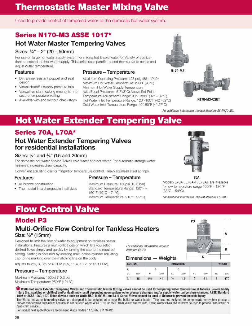
Hot Water Extender Tempering ValveSeries 70A, L70A*Hot Water Extender Tem per ing Valves for residential in stal la tionsSizes: 1⁄2" and 3⁄4" (15 and 20mm)
Series N170-M3 ASSE 1017*Hot Water Master Tempering ValvesSizes: 3⁄4" – 2" (20 – 50mm)For use on large hot water supply system for mixing hot & cold water for Variety of applica -tions to extend the hot water supply. This series uses paraffin -based thermostat to sense and adjust outlet temperature.
Model P3Multi-Orifice Flow Control for Tankless Heat ers
SIzE (dN) dIMENSIONS WEIghT
A B C in. mm in. mm in. mm in. mm oz. gm.
1⁄2 15 15⁄8 41 1⁄2 13 2 51 6 170
Watts hot Water Extender Tempering Valves and Thermostatic Master Mixing Valves can not be used for tem per ing water tem per a ture at fix tures. Severe bodi ly in ju ry (i.e., scald ing or chill ing) and/or death may result depending upon sys tem water pres sure chang es and/or supply water tem per a ture changes. ASSE Standard 1016 or ASSE 1069, 1070 list ed devices such as Watts uSg, MMV-M1 and L111 Se ries Valves should be used at fixtures to prevent possible injury.The Watts hot water tempering valves are designed to be in stalled at or near the boil er or water heater. They are not de signed to com pen sate for system pres sure and/or tem per a ture fluc tu a tions and should not be used where ASSE 1016 or ASSE 1070 valves are re quired. These Watts valves should nev er be used to pro vide “anti-scald” or “anti-chill” ser vice.For radiant heat application we recommend Watts models 1170-M2, L1170-M2.
Used to provide control of tempered water to the domestic hot water system.
Size: 1⁄2" (15mm)Designed to limit the flow of wa ter to equip ment on tankless heat er in stal la tions. Features a multi -orifice de sign which lets you se lect de sired flows simply and quick ly by turning the cap to the re quired setting. Setting is ob tained by lo cat ing multi -or i fice cylinder ad just ing cap to the mark ing over the matching line on the body.
Adjusts to 21⁄2, 3, 31⁄2 or 4 GPM (9.5, 11.4, 13.2, or 15.1 LPM).
Pressure – TemperatureMaximum Pressure: 150psi (10.3 bar) Maximum Temperature: 250°F (121°C)
70A
P3
*
Models L70A , L70A -F, L70AT are avail able for low temperature range 100°F – 130°F (38°C – 54°C).
For additional information, request literature ES-N170-M3.
Thermostatic Master Mixing Valve
N170-M3
N170-M3-CSuT
Features• Dirt&limeresistantpoppetandseat
design• Virtualshutoffifsupplypressurefails• Vandal-resistantlockingmechanismto
secure temperature setting• Availablewithandwithoutcheckstops
Pressure – TemperatureMaximum Operating Pressure: 125 psig (861 kPa0 Maximum Hot Water Temperature: 200°F (93°C) Minimum Hot Water Supply Temperature (with Equal Pressure): 5°F (3°C) Above Set Point Temperature Adjustment Range: 90° - 180°F (32° – 82°C) Hot Water Inlet Temperature Range: 120° -180°F (42° -82°C) Cold Water Inlet Temperature Range: 40° -80°F (4° -27°C)
Pressure – TemperatureMaximum Pressure: 150psi (10.3 bar) Standard Temperature Range: 120°F – 160°F (49°C – 71°C). Maximum Temperature: 210°F (99°C).
For additional information, request literature ES-P3.
Dimensions — Weights
For domestic hot water service. Mixes cold water and hot water. For au to mat ic storage water heat ers it in creas es draw ca pac i ty.
Convenient adjusting dial for “fingertip” tem per a ture con trol. Heavy stain less steel springs.
Features• Allbronzeconstruction• Thermostatinterchangeableinallsizes
For additional information, request literature ES-70A.

27
Expansion TanksUsed to measure and control the flow of water to individual heating units, assuring proper heat transfer. They are used on pipe risers and headers and at pumps to measure and control flow.
Flow Measurement / Balancing Valves
Series CSM-61Sizes: 1⁄2" – 3" (15 – 80mm)Series CSM -61 valves are specifically de signed for ap pli ca tion on low or me di um flow rate HVAC units. Its compact size allows for easy in stal la tion and use on crowd ed pip ing com part -ments. Pro vides pos i tive shutoff, elim i nat ing the need for a sep a rate service valve.
Features• Accurateflowmeasurement• Easytousememorystop• Safe“blowout”proofdesign• Bidirectionalflow• Positiveshutoff• Availablewiththreadedandsolderendconnections• Integraldrainport
CSM-61-M11⁄2" – 1" (15 – 25mm)
CSM-61-M1-T11⁄4" – 3" (32 – 80mm)
CSM-61-M1 1⁄2" – 3" (15 – 80mm)
MOdEL SIzE (dN) dIMENSIONS WEIghT
A C D R in. mm in. mm in. mm in. mm in. mm lbs. kgs.
CSM-61-M1-S 1⁄2 15 211⁄16 68 15⁄8 41 1⁄2 13 13⁄4 45 1.0 0.45 CSM-61-M1-S 3⁄4 20 31⁄8 79 111⁄16 43 9⁄16 15 17⁄8 47 1.3 0.59 CSM-61-M1-S 1 25 313⁄16 97 17⁄8 47 13⁄16 20 21⁄16 52 1.8 0.82 CSM-61-M2-S 11⁄4 32 49⁄16 116 17⁄8 47 11⁄8 29 23⁄16 56 1.5 0.68 CSM-61-M2-S 11⁄2 40 47⁄8 123 2 50 15⁄16 33 25⁄16 59 1.9 0.86 CSM-61-M2-S 2 50 6 153 29⁄16 66 19⁄16 40 25⁄8 67 3.4 1.54 CSM-61-M1-T 1⁄2 15 23⁄8 60 15⁄8 41 1⁄2 13 13⁄4 45 1.0 0.45 CSM-61-M1-T 3⁄4 20 25⁄8 67 111⁄16 43 9⁄16 15 17⁄8 47 1.3 0.59 CSM-61-M1-T 1 25 31⁄8 80 17⁄8 47 13⁄16 20 21⁄16 52 1.9 0.86 CSM-61-M1-T 11⁄4 32 33⁄4 94 17⁄8 47 1 25 23⁄16 56 1.9 0.86 CSM-61-M1-T 11⁄2 40 315⁄16 100 2 50 11⁄16 27 25⁄16 59 2.3 1.04 CSM-61-M1-T 2 50 41⁄2 114 29⁄16 66 15⁄16 33 29⁄16 66 4.0 1.81 CSM-61-M1-T 21⁄2 65 61⁄2 165 41⁄8 104 23⁄16 55 31⁄8 80 13.0 5.90 CSM-61-M1-T 3 80 613⁄16 173 43⁄8 112 27⁄8 73 35⁄8 92 17.0 7.71 Suffix: S = Solder Ends, T = Threaded Ends
A
C
d
r
Dimensions — Weights
BAA/ARRA Compliant** This product complies with the Buy American Act and The American Recovery and Reinvest -ment Act. For more information, visit watts.com.

28
Series HBVHydronic Balancing (Ball) Valve for forced hot water systemsSizes: 1⁄2" – 1" (15–25mm)
Features• Brassbodyconstruction• Slottedstem• Teflon® seats• Solderends
Pressure – TemperatureWorking Pressure Non -Shock: 600psi (41.1 bar) WOG
For additional information, request literature ES-HBV.
SIzE (dN) dIMENSIONS WEIghT
A C in. mm in. mm in. mm lbs. kgs.
1⁄2 15 21⁄16 52 13⁄16 21 .27 .12 3⁄4 20 213⁄16 71 1 25 .59 .27 1 25 35⁄16 160 5⁄16 8 .78 .35
C
A
hBV
Series CSM-81-FSizes: 21⁄2" – 8" (65 – 200mm)Series CSM -81 -F valves are designed for application on medium to high volume flow rate HVAC units. The valve con struc tion allows the flow mea sure ment valve to func tion re li ably both as a bal anc ing valve and bub ble -tight ser vice valve, in closed hot or cold water service.
Features• Accurateflowmeasurement• Flangedendconnections• Checkedmeteringports• Lowtorque• Positiveshutoff• FacetofacedimensionstoANSIB16.10
For additional information, request literature ES-CSM-81.
CSM-81-F
21⁄2"
21⁄2" – 4"
35⁄8"
5" – 8"
A
C
d
rMOdEL SIzE (dN) dIMENSIONS WEIghT
A C D R in. mm in. mm in. mm in. mm in. mm lbs. kgs.
CSM-81-F 21⁄2 65 71⁄2 191 51⁄8 130 315⁄16 100 11⁄16 17 29.5 13.4 CSM-81-F 3 80 8 203 57⁄16 138 43⁄16 113 3⁄4 19 39 17.7 CSM-81-F 4 100 9 229 61⁄2 165 415⁄16 125 15⁄16 24 61.5 27.9 CSM-81-F 5 125 101⁄2 267 73⁄4 197 6 152 1 25 88 39.9 CSM-81-F 6 150 101⁄2 267 73⁄4 197 6 152 1 25 100 45.4 CSM-81-F 8 200 111⁄2 292 93⁄16 233 61⁄2 165 11⁄8 29 172 78.0
Flow Measurement / Balancing Valves
H
CSM-81-F
Dimensions — Weights
Dimensions — Weights
BAA/ARRA Compliant** This product complies with the Buy American Act and The American Recovery and Reinvest -ment Act. For more information, visit watts.com.

29
Flow Measurement / Balancing Valves
Series CSM-91 - Straight
SIzE (dN) dIMENSIONS FLANgEd dIAMETEr SPACEr WEIghT
A C D F 125#in. mm. in. mm in. mm in. mm in. mm in. mm in. mm lbs. kgs.
21⁄2 65 12 305 95⁄8 245 23⁄4 70 29⁄16 64 7 178 1 25 19 8.63 80 12 305 101⁄2 267 27⁄16 61 3 76 71⁄2 191 1 25 24 10.94 100 14 356 109⁄16 264 3 76 37⁄16 87 91⁄4 235 11⁄4 32 42 19.05 125 171⁄2 445 131⁄16 332 35⁄8 92 415⁄16 124 10 150 11⁄4 32 81 36.76 150 2011⁄16 526 133⁄4 349 47⁄16 111 57⁄8 149 11 279 2 50 120 54.48 200 283⁄16 716 245⁄8 626 511⁄16 145 77⁄8 200 131⁄2 343 21⁄4 57 310 140.6
10 250 30 762 261⁄2 673 69⁄16 161 915⁄32 240 16 406 21⁄4 57 460 208.6
Series CSM-91 - Angle - Field Convertible*
SIzE (dN) dIMENSIONS FLANgEd dIAMETEr SPACEr WEIghT
A C D1 E F1 F2 125#in. mm. in. mm in. mm in. mm in. mm in. mm in. mm in. mm in. mm lbs. kgs.
21⁄2 65 101⁄8 257 95⁄8 245 45⁄8 117 73⁄8 187 29⁄16 64 23⁄4 70 7 178 1 25 19 8.63 80 1013⁄16 275 101⁄2 267 37⁄8 98 83⁄8 213 3 76 27⁄16 61 71⁄2 191 1 25 24 10.94 100 125⁄8 321 109⁄16 264 43⁄8 111 95⁄8 245 37⁄16 87 3 76 91⁄4 235 11⁄4 32 42 19.05 125 155⁄8 397 131⁄16 332 51⁄2 140 12 305 415⁄16 124 35⁄8 92 10 150 11⁄4 32 81 36.76 150 189⁄16 471 133⁄4 349 65⁄8 168 141⁄8 359 57⁄8 149 47⁄16 111 11 279 2 50 120 54.48 200 245⁄8 625 245⁄8 626 93⁄16 234 1815⁄16 481 77⁄8 200 511⁄16 145 131⁄2 343 21⁄4 57 310 140.6
10 250 267⁄8 683 261⁄2 673 93⁄4 248 205⁄16 516 915⁄32 240 69⁄16 161 16 406 21⁄4 57 460 208.6*Note: Series CSM -91 valves are shipped as straight pattern from factory. To convert to angle pattern refer to installation sheet shipped with valve.
Series CSM-91Sizes: 21⁄2" – 10" (65 – 250mm)For medium or large flow rate HVAC systems, pump pack ag es, and cooling tow ers. They feature a multi -turn ad just ment range for max i mum con trol , pres sure dif fer en tial readout ports on both sides of the valve to allow for eas i er in stal la tion and positive shutoff for ser vic ing equip ment.
Features• Multi-turnadjustment• Interchangeablemeteringanddrainportsonbothsidesofvalve• Positiveshutoff• Tamper-proofmemorystop• Micrometertypehandwheeladjustment-visuallyreadablefromadistance• Fieldconvertibleforstraightoranglepattern• Groovedendconnectionswithoptionalflangeadapters
CSM-91 - Factory Standard Straight design
Series CSM-91 Field Convertible Angle Pattern
CSM-91Straight
CSM-91Angle
A
d
C
FSpacer
Spacer
Flange diameter
Flange diameter
AF2 E
C
d1
F1
Dimensions — Weights

30
Protect boilers against emergency low water conditions.
Series N50 Low Water Cut-offsSize: 1" (25mm)
N50
• Protectshotwaterheatingboilersagainst emergency low water conditions
• Usedonlowpressureprocessboilers
Specifications• Floatchamberhas1"(25mm)NPT
female top and bottom connections.
Models N50S – Single switch assembly for burner service with extra terminal for line voltage single pole, double throw service N50D – Dual switch assembly for line voltage burner service and independent low (or high) voltage alarm, feed valve or pump starter
For additional information, request literature IS-N89.
Series SAN89, SAN50 Float and Switch Assemblies for Servicing Low Water Cut-offsSizes: 1⁄2" – 1"(15–25mm)
SAN89
One piece unit facilitates installation and as -sures user of the most up -to -date construc -tion
ModelsSAN89D – Complete float and dual switch assembly. Maximum steam pressure 15psi (103.4 kPa). SAN89S – Same as above, but with single switch assembly for Watts N89S and N101S.SAN50D – Complete assembly with dual switch. Maximum boiler pressure 50psi (344.8 kPa).SAN50S – Same as above, but furnished with single switch assembly.
For additional information, request literature IS-N89.
Low Water Cut-Offs

31
Hydronic Specialties
Series CVY, CVYSWye Pattern Bronze Check Valves for Water and Steam ServiceSizes: 3⁄8" – 2" (10 – 50mm)
Series HWAHot Water Angle ValvesSizes: 1⁄2" – 11⁄4" (15 – 32mm)1⁄2" – 11⁄4"bronze—FIPxmaleunion. 1⁄2" – 3⁄4"bronze—solderxmaleunion. Phenolic handwheel.
Working Pressure non-shock for hot water: 60psi (413.7 kPa).
Series ULUnion ElbowsModelsUL-1 - 1⁄2" – 11⁄4" (15 – 32mm)
Bronze body, FIP x male union UL-2 - 1⁄2", 3⁄4" (15, 20mm)
Bronze body, solder x male union
For additional information, request literature ES-UL.
MOdEL SIzE (dN) WEIghT
in. mm lbs. kgs.
CVY 3⁄8 10 .62 .28CVY 1⁄2 15 .62 .28CVY 3⁄4 20 .88 .40CVY 1 25 1.32 .60CVY 11⁄4 32 2.00 .91CVY 11⁄2 40 2.87 1.30CVY 2 50 4.76 2.16
CVYS 1⁄2 15 .60 .27 CVYS 3⁄4 20 .82 .37 CVYS 1 25 1.24 .56 CVYS 11⁄4 32 1.87 .85 CVYS 11⁄2 40 2.71 1.23 CVYS 2 50 4.76 2.16
For industrial and commercial lines to prevent reverse flow.
Rating: 125 WSP/200 WOG
Features• Bronzebody• Metaltometalseating• Wyetypepattern
ModelsCVY – Sizes 3⁄8" – 2" (10 – 50mm), IPS threaded connections
CVYS – Sizes 1⁄2" – 2" (15 – 50 mm), CxC solder connections,
Pressure - TemperatureMaximum Steam: 15psi (103.4 kPa)
For additional information, request literature ES-CVY or ES-CVYS.
Series 600Bronze Silent Check ValvesSizes: 1⁄4" – 2" (8 – 50 mm)
Features• PTFEseatsandbrassdisc• Installinahorizontalorverticalposition• Stainlesssteelguiderodandspring• Silentcheckoperation• Preventswaterhammer
For additional information, request literature ES-600.
CVy
600
hWA
uL-1
Dimensions — Weights
For additional information, request literature ES-HWA.

32
Expansion Tanks
A
B
C
OTV-M1Series OTV-M1Oil Tank ValvesFeatures• 1⁄4 -Turn ball valve design• Heavydutybrass• Adjustablepackingnut• PTFEseatandpacking
PressureWorking Pressure Non -Shock: 125psi WOG
MOdEL SIzE dIMENSIONS WEIghT
A B C
in. mm in. mm in. mm in. mm lbs. kgs
OTV-FL-M1 1⁄2 M x 3⁄8 FL 15 x 10 415⁄16 125 29⁄16 65 115⁄16 49 .76 .34
OTV-M-M1 1⁄2 M x 3⁄8 M 15 x 10 41⁄2 114 29⁄16 65 115⁄16 49 .70 .32
Hydronic Specialties
Model RBFFResidential Boiler Fill FittingSize: 1⁄2" (15mm)Model RBFF Residential Boiler Fill Fitting provides a convenient solutiontocomplywithboilermanufacturers’pipingrequirementsand provide ease of service for expansion tanks and water pressure regulator valves in closed -loop hot water heating systems. Using a unique 3 -way ball valve design, the RBFF eliminates up to twelve 1/2 inch fittings in a compact package.
Features•One-piececonstruction,eliminatingupto11threadedjoints•Unique3-wayballvalveforisolationofwaterpressureregulator
and expansion tank from system pressure•Drainportwithintegralballvalveforunloadingpressurefromwa -
terside of expansion tank diaphragm for air charge servicing and maintenance. Drain port can also be used for a variety of system draining and filling operations.
•0to30psi(0to87kPa)pressuregaugeforconvenient system pressure reference
Pressure – TemperatureMaximum Working Pres sure: 125psi (860 kPa) Maximum Inlet Temperature: 250°F (121°C)
For additional information, request literature ES-RBFF.
rBFF
Fig. 1
Dimensions — Weights
For additional information, request literature ES-OTV-M1.

33
Hydronic Specialties
Series BDBrass Boiler DrainsSizes: 1⁄2" x 3⁄4"— 3⁄4" x 3⁄4"(15 x 20mm – 20 x 20mm)Pressure – Temperature Pressure Rating: 200psi (13.8 bar) non -shock WOG Maximum Temperature: 180°F (82°C)
ModelsBD1C Size 1⁄2" (15mm) dual connection, solder or
male IPS x 3⁄4" (20mm) hose thread connection, angle pattern
BD2 Size 3⁄4" (20mm) male IPS x 3⁄4" (20mm) hose thread connection, angle pattern
BD2C Size 3⁄4" (20mm) MIP x 3⁄4" (20mm) hose thread connection, angle pattern
BD3F Size 1⁄2" (15mm) female IPS x 3⁄4" (20mm) hose thread connection, angle pattern
BD4F Size 3⁄4" (20mm) female IPS x 3⁄4" (20mm) hose thread connection, angle pattern
BD5 Size 1⁄2" (15mm) dual connection, solder or male IPS x 3⁄4"(20mm) hose thread connection, straight pattern, hose thread connection
BD6 Size 3⁄4" (20mm) Male IPS x 3⁄4" (20mm) hose thread connection, straight pattern
For additional information, request literature ES-BD.
Bd-QT3⁄4" (20mm)
Series BD-QTQuarter-Turn Boiler DrainsSizes: 1⁄2" and 3⁄4" (15 and 20mm)Provide speed and convenience of quarter -turn ball valve performance for boiler drain or sill cock applications. Uses rugged forged brass body, adjustable Teflon® stem packing, and aluminum tee handle. The 1⁄2" (15mm) model has a dual -pattern combination threaded and solder end by 3⁄4" (20mm) hose connection. The 3⁄4" (20mm) model is available in either solder or threaded ends.
Features• Quarter-turnballvalvedesign• Positiveshutoff• RuggedaluminumTee-handledesign• AdjustableTeflon® stem packing
Pressure – TemperatureMaximum Pressure: 200psi (13.8 bar) Maximum Temperature: 250°F (121°C)
For additional information, request literature ES-BD-QT.
MOdEL SIzE (dN) dIMENSIONS WEIghT
A B C in. mm in. mm in. mm in. mm lbs. kgs.
BD-QT 1⁄2 15 33⁄8 86 21⁄4 57 15⁄16 24 .04 .018 BD-QT 3⁄4 20 41⁄8 104 27⁄16 62 11⁄8 29 .05 .022
A
B
C
Bd1C Bd2
Bd3F Bd4F
Bd5 Bd6
Dimensions — Weights

34
Hydronic Specialties
Series GBV2-Piece, Brass Gas Ball ValvesSizes: 3⁄8" – 1" (10 – 25mm)• Brasstwo-piecebodyconstruction• Availablewithteehandleorsquarehandle
ModelsGBV – Sizes: 3⁄8" – 1" (10 – 25mm), NPT female connections and tee handle.
GBV-FL – Sizes: 1⁄2" x 3⁄8", 1⁄2" x 1⁄2", 3⁄4" x 15⁄16" (15 x 10, 15 x 15, 20 x 24mm), Female NPT x Flare connections and tee handle.
GBV and GBV-FL – rated 20°F – 125°F ( -29° – 52°C). CSA approved @ 1⁄2, 2 and 5psi (3.4, 13.8, 34.5 kPa). UL listed @ 5psi (34.4 kPa).
For additional information, request literature ES-GBV.
Series GBV-1One Piece Gas Ball ValvesSizes: 1⁄2" and 3⁄4" (15 and 20mm)• Sizes1⁄2" and 3⁄4" (15 and 20mm) NPT female connections.• Blowoutproofstemdesign.
Features• Blowoutproofstemdesign• One-piecebody• ULapproved@5psi(34.4kPa)• ApprovedbyCSA@1⁄2, 2 and 5psi (3.4, 13.8, 34.5 kPa). UL Listed @ 5psi (34.4 kPa).• Capacity:1⁄2" @ 295 ft.3/hr., 3⁄4" @ 760 ft.3/hr• TestedunderStandardsZ21.15IASRequirement
For additional information, request literature ES-GBV-1.
gBV
gBV-1
MOdEL SIzE (dN) dIMENSIONS WEIghT
A C D K E in. mm in. mm in. mm in. mm in. mm in. mm lbs. kgs.
GBV 3⁄8 10 113⁄16 46 13⁄8 35 3⁄8 10 13⁄4 45 – – .41 .19GBV 1⁄2 15 23⁄16 55 13⁄8 35 3⁄8 10 13⁄4 45 – – .51 .23GBV 3⁄4 20 27⁄16 62 17⁄16 36 9⁄16 15 13⁄4 45 – – .73 .33GBV 1 25 27⁄8 73 19⁄16 40 13⁄16 20 13⁄4 45 – – .59 .27GBV-FL 1⁄2 x 3⁄8 15 x 10 27⁄16 62 11⁄4 32 1⁄2 13 13⁄4 45 – – .53 .24GBV-FL 1⁄2 x 1⁄2 15 x 15 21⁄2 64 11⁄4 32 1⁄2 13 13⁄4 45 – – .58 .26GBV-FL 3⁄4 x 15⁄16 20 x 24 31⁄16 77 17⁄16 36 5⁄8 16 13⁄4 45 – – .86 .39
k
C
d
A
EE
Note: This valve is not to be used as a mainline shutoff valve. Refer to literature ES-FBV-3 for mainline shutoff applications.
SIzE (dN) dIMENSIONS WEIghT
A C D I in. mm in. mm in. mm in. mm in. mm lbs. kgs.
1⁄2 15 25⁄16 59 17⁄16 37 15⁄16 24 1⁄2 15 .41 .19 3⁄4 20 211⁄16 68 15⁄8 41 11⁄8 29 9⁄16 15 .65 .30
C
d
A
IBall Orifice
Dimensions — Weights
Dimensions — Weights

35
MOdEL SIzE (dN) dIMENSIONS WEIghT
A C D L in. mm in. mm in. mm in. mm in. mm lbs. kgs.
B6000 1⁄4 8 3⁄8 5 127 13⁄4 44 5⁄8 16 21⁄16 54 0.6 .3 B6000 3⁄8 10 3⁄8 5 127 13⁄4 44 5⁄8 16 21⁄16 54 0.6 .3 B6000 1⁄2 15 1⁄2 5 127 13⁄4 44 5⁄8 16 21⁄4 57 0.6 .3 B6000 3⁄4 20 11⁄16 55⁄16 135 2 51 3⁄4 19 213⁄16 71 1.0 .5 B6000 1 25 7⁄8 51⁄2 140 21⁄4 57 7⁄8 22 37⁄16 87 1.6 .7 B6000 11⁄4 32 1 7 178 21⁄2 64 11⁄8 29 37⁄8 98 2.2 1.0 B6000 11⁄2 40 11⁄4 7 178 3 76 15⁄16 33 41⁄4 108 3.2 1.5 B6000 2 50 11⁄2 11 279 315⁄16 100 11⁄2 38 413⁄16 122 4.9 2.2 B6000 21⁄2 65 2 119⁄16 293 4 102 23⁄16 56 61⁄2 165 13.2 6.0 B6000 3 80 21⁄2 115⁄8 295 41⁄4 108 23⁄8 60 613⁄16 173 17.5 7.9 B6000 **4 100 3 151⁄8 384 413⁄16 122 215⁄16 70 711⁄16 195 29.3 13.3 B6001 3⁄8 10 3⁄8 51⁄16 128 11⁄2 38 5⁄8 16 25⁄16 59 0.5 .2 B6001 1⁄2 15 1⁄2 53⁄16 132 13⁄4 44 5⁄8 16 23⁄8 60 0.6 .3 B6001 3⁄4 20 11⁄16 53⁄4 146 2 51 3⁄4 19 35⁄16 70 1.1 .5 B6001 1 25 7⁄8 6 152 21⁄4 57 7⁄8 22 33⁄4 95 1.4 .6 B6001 11⁄4 32 1 8 203 21⁄2 64 11⁄8 29 41⁄2 108 2.0 .9 B6001 11⁄2 40 11⁄4 81⁄8 207 3 76 15⁄16 33 5 127 3.3 1.5 B6001 2 50 11⁄2 117⁄16 290 35⁄16 84 11⁄2 38 61⁄4 159 5.2 2.4 B6001 21⁄2 65 2 121⁄8 308 4 102 23⁄16 56 75⁄8 186 13.2 6.0 B6001 3 80 21⁄2 125⁄16 313 †41⁄4 108 23⁄8 60 83⁄16 208 15.6 7.1**Virgin PTFE seats on 4" size, maximum temperature 350°F. † Solder ends
Series B6000, B6001†
2-Piece, Bronze, Standard Port for residential, commercial and in dus tri al use Ball ValvesSizes: 1⁄4" – 4" (8 – 100mm)• GlassreinforcedDurafill1⁄2" – 3" (15 – 80mm) or Virgin PTFE 4" (100mm) seats standard• Hardchromeplatedbrassball• Sizes1⁄4" – 2" (8 – 50mm) pressure rated at 150 WSP/600 WOG, 21⁄2" – 4" (50 – 100mm)
400 WOG (non -shock) and 125psi (8.6 bar) saturated steam• Adjustablestempackinggland• Suitablefortemperaturesfrom0°F–450°F(-18°C–232°C)
B60001⁄4" – 4" (8 – 100mm)
Threaded Ends
B60013⁄8" – 3" (10 – 80mm)
†Solder EndsAvailable OptionsCC – Cap & Chain 1⁄2", 3⁄4" (13mm, 19mm)GS – Grounded stemTH – Tee handleRH – Round handle 1⁄4" – 2" (6 – 51mm)SS – Stainless steel ball and stemSH – Stainless steel handle and nutXH – Extended handleOV – Oval handle, low profileVT (01) – Virgin PTFE seat materialBS – Balancing stop04 – Mineral -filled PTFE seats and seals
(available in all 316SS ball and stem option)
*Z15 – Less lever and nutChain lever kit 3⁄4", 1" (20, 25mm)
Available Optional Valves
UL Listed: Flammable Liquids (YRBX)
Compressed Gas (YQNZ)
Fire Protection (HNFX) 1⁄4" – 2" (8 – 51mm)
LP Gas (YSDT) 1⁄4" – 3" (8 – 80mm)
Natural/Manufactured Gas (YRPV) 1⁄4" – 3" (8 – 80mm)
For #1 and #2 Fuel Oils (MHKZ) 1⁄4" – 3" (8 – 80mm)
For additional information, request literature ES-B6000.
A
L
C
d
Dimensions — Weights
Hydronic Specialties
Pressure – TemperatureTemperature Range: 0°F – 450°F ( -18°C – 232°C) @ 50psi (3.4 bars) Pressure Range: 1⁄4"–3"(8–80mm),600psi(41bar)WOGnon-shock;150psi(10bar)WSP 4"(100mm),400psi(28bars)WOGnon-shock;125psi(8.6bar)WSP Use stainless steel trim (option SS) for steam pressures over 150psi (10 bar).
BAA/ARRA Compliant** This product complies with the Buy American Act and The American Recovery and Reinvest -ment Act. For more information, visit watts.com.

36
Expansion TanksHydronic Specialties
Series FBV2–Piece, Full Port Bronze Ball ValvesSizes: 1⁄2" – 2" (15 – 50mm)
Features • Excellentforthrottlingandbalancingapplications• Fornon-abrasiveliquidsorgases• Two-piececonstruction
Pressure – TemperatureTemperature Range: 0°F – 350°F ( -18°C – 177°C) @ 50psi (3.4 bar)
Maximum Working Pressure: 600psi (41 bar) WOG non -shock @ 100°F (38°C) and 125psi (8.6 bar) WSP
ModelsFBV - NPT female connections
For additional information, request literature ES-FBV.
SIzE (dN) dIMENSIONS WEIghT
C E H I LIn. mm In. mm In. mm In. mm In. mm In. mm lbs. kgs.
1⁄2 15 13⁄4 44 13⁄32 28 33⁄8 86 1⁄2 13 23⁄16 56 .6 .33⁄4 20 21⁄16 52 19⁄32 33 35⁄8 92 3⁄4 19 29⁄16 65 .8 .41 25 21⁄2 64 17⁄32 31 43⁄8 111 1 25 31⁄16 78 1.5 .7
11⁄4 32 25⁄8 67 19⁄16 40 43⁄8 111 11⁄4 32 31⁄2 89 2.5 1.111⁄2 40 31⁄8 79 15⁄16 49 61⁄8 156 11⁄2 38 37⁄8 98 3.5 1.62 50 31⁄2 89 27⁄32 56 61⁄8 156 2 51 47⁄16 113 5.5 2.5
h
C
LE
JI
FBV
Dimensions — Weights

37
Hydronic Specialties
Series FBV-3C, FBVS-3C2-Piece Full Port Brass Ball ValvesSizes: 1⁄4" – 4" (8 – 100mm)
Features• CertifiedtoNSFtoNSF/ANSIstandard61/8• CSAapprovedthreadedvalvesonly1⁄4" – 3" (15 – 80mm)• Metaltometaladapterbodysealtoeliminateadapterleaksafter
soldering• Bottomloaded,blow-outproofstem• AdjustablestempackingglandandstemO-ring• VirginPTFEstempackingseal,thrustwasher,andseats• ComplieswithMSS-SP-110FBV-3C – Sizes: 1⁄4" – 4" (8 – 100mm), NPT female connections.FBVS-3C – Sizes: 1⁄2" – 3" (15 – 80mm), solder connections.
Pressure – TemperaturePressure Ratings: FBV-3C: Sizes 1⁄4" – 2" (8 – 50mm) 600psi (41 bar) WOG non -
shock, 150psi (10.3 bar) WSP Sizes 21⁄2" and 4" (65 and 100mm) 400psi (27.5 bar) WOG non -shock, 125psi (8.6 bar) WSP
FBVS-3C: Sizes 1⁄2" – 2" (15 – 50mm) 600psi (41 bar) WOG non -shock, 150psi (10.3) WSP Sizes 21⁄2" and 3" (65 and 80mm) 400psi (27.5 bar) WOG non -shock, 125psi (8.6 bar) WSP
For additional information, request literature ES-FBV-3C.
SIzE (dN) dIMENSIONS WEIghT
C H H1 I L L1
in. mm in. mm in. mm in. mm in. mm in. mm in. mm lbs. kgs. 1⁄4 8 17⁄16 36 33⁄16 81 – – 3⁄8 10.5 113⁄16 46 — — .3 .13⁄8 10 17⁄16 36 33⁄16 81 – – 3⁄8 10.5 113⁄16 46 — — .3 .11⁄2 15 115⁄16 50 35⁄8 91 35⁄8 91 19⁄32 12.5 23⁄8 60 21⁄8 53 .5 .23⁄4 20 21⁄16 52 41⁄2 114 41⁄2 114 13⁄16 20.0 211⁄16 68 213⁄16 72 .8 .31 25 27⁄16 62 415⁄16 125 415⁄16 125 1 25.0 31⁄8 80 33⁄8 86 1.4 .6
11⁄4 32 25⁄8 66 415⁄16 125 415⁄16 125 11⁄4 31.0 311⁄16 90 37⁄8 98 2.0 .911⁄2 40 215⁄16 75 51⁄2 140 51⁄2 140 11⁄2 39.0 37⁄8 99 43⁄8 112 2.6 1.22 50 31⁄8 80 77⁄8 200 77⁄8 200 115⁄16 50.0 47⁄16 113 55⁄16 135 4.0 1.8
21⁄2 65 45⁄16 109 97⁄8 250 97⁄8 250 23⁄8 60.5 51⁄2 140 65⁄16 161 9.0 4.13 80 45⁄8 118 97⁄8 250 97⁄8 250 215⁄16 74.0 61⁄4 159 73⁄16 182 12.8 5.84 100 53⁄8 136 95⁄8 245 – – 4 101.6 77⁄16 189 – – 17.7 8.0
h
I
L
C
I
h1
C
L1
FBV-3C FBVS-3C
Dimensions — Weights
Approvals 1/4" – 3" (8 - 80mm) FBV -3C
1/2" – 1" (15 - 25mm) FBV -3C -TH Certified to NSF/ANSI standard 61/8*
1/2" – 3" (15 – 80mm) FBVS -3C 1/2" – 1" (15 – 25mm) FBVS -3C -TH Certified to NSF/ANSI standard 61/8* *Domestic cold water at 73ºF (23ºC)
1/2" – 2" (15 – 50mm) FBV -3C UL/FM approved 1/2" – 1" (15 – 25mm) FBVL -3C -TH
1/2" – 2" (15 – 50mm) FBVS -3C UL Listed 1/2" – 1" (15 – 25mm) FBVS -3C -TH
Gas Approvals (Threaded Valves Only)1/4" – 3/8" (8 – 10mm)
ASME B16.33, CSA
1/2 psig, 5psig, (14, 34 kPa)
@ -40ºF to 125ºF ( -40ºC to 52ºC)1/2" – 2" (15 – 50mm) ASME B16.33, CSA
1/2 psig, 5psig, and 125psig (14, 34 and 862 kPa) @ -40ºF to 125ºF ( -40ºC to 52ºC)
21/2" – 3" (65 – 80mm)
ASME B16.38, CSA
1/2 psig, 5psig, and 125psig (14, 34 and 862 kPa) @ -40ºF to 125ºF ( -40ºC to 52ºC)
approved

38
Hydronic Specialties
Series FBV-4, FBVS-42-Piece, Full Port, Brass Ball ValvesSizes: 1⁄4" – 3" (8 – 80mm)
Features•CertifiedtoNSF/ANSIstandard61/8•CSAapprovedthreadedvalvesonly1⁄4" – 3" (15 – 80mm)•Metal-to-metaladapterbodysealtoeliminateadapterleaksaftersoldering•FluorocarbonelastomerstemO-ringpreventsstemleaks•Adjustablestempackinggland•PTFEstempackingseal,thrustwasher,andseats•Bottomloadedblowoutproofstem•Machinedchromeplatedbrassball•ValvescomplytoMSS-SP-110standard
ModelsFBV-4 1⁄4" – 3" (8 – 80mm) threaded end connections
FBVS-4 1⁄2" – 3" (15 – 80mm) solder end connections*
Pressure — TemperatureTemperature Range: -40ºF to 400ºF ( -40ºC to 204ºC)
Pressure Rating:
Sizes 1⁄4" – 2" (8 – 50mm) 600psi (41 bar) WOG non -shock, 150psi (10.3 bar) WSP
Sizes 21⁄2" and 3" (65 and 80mm) 400psi (28 bar) WOG non -shock, 125psi (8.6 bar) WSP
h
C
L FBV-4
I
h
C
L1 FBVS-4
I
FBV-4
FBVS-4
Dimensions — Weights
SIzE (dN) dIMENSIONS WEIghT
C H I L L1 FBV-4 FBVS-4in. mm in. mm in. mm in. mm in. mm in. mm lbs. kg. lbs. kg.1⁄4 8 113⁄16 46 37⁄16 87 7⁄16 11 13⁄4 45 — — 0.4 0.16 — —3⁄8 10 113⁄16 46 37⁄16 87 1⁄2 13 13⁄4 44.7 — — 0.4 0.17 — —1⁄2 15 113⁄16 46 37⁄16 87 1⁄2 13 2 50 21⁄16 53 0.4 0.18 0.4 0.163⁄4 20 21⁄16 53 315⁄16 101 11⁄16 18 21⁄4 57 25⁄8 67 0.6 0.27 0.5 0.241 25 27⁄16 62 41⁄4 108 15⁄16 24 213⁄16 71 34⁄16 83 1.1 0.49 1.0 0.44
11⁄4 32 21⁄2 64 41⁄4 108 13⁄16 31 31⁄8 80 311⁄16 93 1.5 0.68 1.4 0.6411⁄2 40 3 76 55⁄16 135 17⁄16 37 37⁄16 88 43⁄16 107 2.3 1.06 2.1 0.952 50 31⁄2 89 6 153 2 51 41⁄8 105 55⁄16 135 3.7 1.69 3.8 1.7421⁄2 65 41⁄16 104 73⁄8 188 21⁄2 64 55⁄16 134 63⁄16 158 7.9 3.57 7.2 3.273 80 41⁄2 114 73⁄4 197 3 76 61⁄8 155 71⁄4 184 11.8 5.37 11.0 4.99
Approvals ¼" – 3" FBV -4
½"–3"FBVS-4 Certified to NSF/ANSI Standard 61/8 Domestic cold water at 73°F
Gas Approvals (Threaded Valves Only)¼" – 3" CSA ½psig,5psig @ -40°F to 125°F

39
Hydronic Specialties
MOdEL SIzE (dN) dIMENSIONS CV ratings WEIghT
C D L in. mm in. mm in. mm in. mm lbs. kgs.† EMVII-6400SS-115-8 1⁄4 8 77⁄8 200 5⁄8 16 21⁄4 57 6.3 8.75 4.0† EMVII-6400SS-115-8 3⁄8 10 77⁄8 200 5⁄8 16 21⁄4 57 6.3 8.75 4.0† EMVII-6400SS-115-8 1⁄2 15 77⁄8 200 5⁄8 16 21⁄4 57 9.0 8.75 4.0† EMVII-6400SS-115-35 3⁄4 20 8 203 3⁄4 19 27⁄8 73 24.5 9.25 4.2† EMVII-6400SS-24-40 1 25 81⁄8 206 1 25 33⁄8 86 45.5 10.25 4.6† EMVII-6400SS-115-35 11⁄4 32 87⁄8 225 21⁄8 29 4 102 45.5 10.75 4.9† EMVII-6400SS-24-40 11⁄2 40 91⁄8 232 13⁄8 35 43⁄8 111 73.0 11.75 5.3† EMVII-6400SS-24-40 2 50 91⁄2 241 15⁄8 41 47⁄8 124 102.0 14.25 6.5
†† EMVII-6400SS-115-25 21⁄2 65 14 356 – – 61⁄2 165 200.0 23.00 10.4†† EMVII-6400SS-115-25 3 80 141⁄2 368 – – 67⁄8 175 300.0 27.50 12.5
Series EMVII-6400SSElectric Motor ValvesSizes 1⁄4" – 3" (8 – 80mm)
† Sizes 1⁄4" – 2 (8 – 50mm) are available 115 -8, 115 -35 and 24 -40.†† Sizes 21⁄2" & 3" (65 & 80mm) also available 24 – 25. Contact your local Watts Agent.
gV
EMVII-6400SS
Se ries GV, GVS†, GLVBronze Gate and Globe ValvesSizes: 1⁄4" – 4" (8 – 100mm)
Features• Threadedbonnet• Non-risingstem• BronzebodyGV - 125 WSP to 353°F/200 WOG GVS - 125 WSP to 353°F/200 WOG
For additional information, request literature ES-GV, ES-GVS or ES-GLV.
Series GV - bronze gate valves - threaded IPS connections
Dimensions — Weights SIzE (dN) dIMENSIONS WEIghT
A C Kin. mm in. mm in. mm in. mm lbs. kgs.1⁄4 8 15⁄8 41 3 76 115⁄16 43 .62 .283⁄8 10 15⁄8 41 33⁄16 81 115⁄16 43 .62 .281⁄2 15 13⁄4 44 33⁄8 86 23⁄16 55 .71 .323⁄4 20 115⁄16 49 35⁄8 92 23⁄8 60 .93 .421 25 21⁄8 54 47⁄16 111 29⁄16 64 1.2 .5411⁄4 32 23⁄8 60 5 127 23⁄4 70 2.0 .9111⁄2 40 21⁄2 64 53⁄8 137 31⁄8 79 2.7 1.222 50 27⁄8 73 61⁄2 165 39⁄16 90 3.4 1.5421⁄2 65 31⁄2 89 8 200 45⁄16 108 6.4 2.903 80 315⁄16 100 93⁄16 234 415⁄16 124 29.3 13.294 100 43⁄4 121 103⁄4 273 53⁄4 146 118.0 53.57
Series GVS - bronze gate valves - solder ends3⁄8 10 13⁄4 44 33⁄8 86 21⁄8 54 .62 .281⁄2 15 13⁄4 44 33⁄8 86 21⁄8 54 .62 .283⁄4 20 23⁄8 60 35⁄8 92 23⁄8 60 .88 .401 25 213⁄16 71 47⁄16 121 25⁄16 58 1.15 .5211⁄4 32 3 76 5 127 23⁄4 70 1.72 .7811⁄2 40 33⁄8 86 57⁄16 138 31⁄8 79 1.85 .842 50 4 100 61⁄2 165 31⁄2 89 3.53 1.6021⁄2 65 41⁄2 114 85⁄16 209 43⁄8 111 5.95 2.703 80 53⁄16 132 93⁄16 234 415⁄16 124 8.82 4.00
Series GLV - bronze globe valves - threaded bonnet - swivel type disc, threaded ends1⁄4 8 113⁄16 41 215⁄16 74 2 50 .71 .323⁄8 10 113⁄16 41 215⁄16 74 2 50 .71 .321⁄2 15 115⁄16 49 215⁄16 74 25⁄16 58 .74 .343⁄4 20 21⁄4 57 31⁄8 79 21⁄2 64 1.25 .571 25 25⁄16 105 33⁄4 95 213⁄16 71 1.93 .8811⁄4 32 215⁄16 74 41⁄8 105 31⁄2 89 2.33 1.0611⁄2 40 35⁄16 114 43⁄4 121 35⁄8 92 4.20 1.902 50 37⁄8 98 51⁄2 140 41⁄8 105 5.50 2.50
A
Copen
k
Combines our positive shutoff, quarter -turn ball valves with a highly efficient, reliable, electric op er a tor. Com -pact, completely assembled. Steam work ing pressure 100psi (6.9 bar), 600psi (41.4 bar) WOG for 1⁄4" – 2" (8 – 50mm), 400psi (27.6 bar) WOG for 21⁄2" and 3" (65 and 80mm). Maximum operating tem per a ture 150°F (66°C). 24VAC and 115 VAC models.
Features• Zonecontrolvalveforspaceheatingwith
hot water or steam• Zonecontrolvalveforairconditioning
with chilled water
For additional information, request literature ES-EMVII-6400SS.
C
L
d
Dimensions — Weights

40
Hydronic Specialties
Series TPTemperature or Pressure Test PlugsSizes: 1⁄4" and 1⁄2" NPT (8, 15mm)Take pressure or temperature readings quickly and eliminate the need for leav ing costly gauges or temperature recorders on the line. Can be used on various applications of gas, air, water or chem i cals to 500psi (34.5 bar).
The pressure gauge adapter has a .076 diameter probe of 300 Se ries stainless steel with brass union nut. The probe operates in either 1⁄4" or 1⁄2" (8 or 15mm) NPT test plugs. Plug ex -tensions are also available in 1⁄4" and 1⁄2" (8 and 15mm) NPT sizes to ac com mo date insulated pipe ap pli ca tions.
TP-T
TPg
1⁄2" TP-x (15mm)
1⁄4" TP-x (8mm)
1⁄2" TP-gA1 (15mm)
1⁄2" TP-T (15mm)
1⁄4" TP-T (8mm)
MOdEL SIzE (dN) MATErIAL MAx TEMP MAx PrESSurE WEIghT
in mm ˚F ˚C psi bar lbs kgs.
TP-N (Neoprene) 1⁄4" NPT 8mm NPT Brass 200°F 93°C 500 34 .09 .04TP-E (EPDM) 1⁄4" NPT 8mm NPT Brass 275°F 135° C 500 34 .09 .04TP-V (Viton®) 1⁄4" NPT 8mm NPT Brass 400°F 204°C 500 34 .09 .04TP-N (Neoprene) 1⁄2" NPT 15mm NPT Brass 200°F 93°C 500 34 .19 .09TP-E (EPDM) 1⁄2" NPT 15mm NPT Brass 275°F 135° C 500 34 .19 .09TP-V (Viton®) 1⁄2" NPT 15mm NPT Brass 400°F 204°C 500 34 .19 .09Extensions
TP-X • 3"(76mm) 1⁄4"m x 1⁄4"f 8m x 8 f Brass – – – – .25 .11TP-X • 3"(76mm) 1⁄2"m x 1⁄2"f 15m x 15 f Brass – – – – .63 .29Thermometer
TP-T 2° graduation SS 220°F 104°C – – – – Gauges
TPG-30 1⁄4" NPT 8mm NPT 185°F 85˚C 30 2 .06 .03TPG-160 1⁄4" NPT 8mm NPT 185°F 85˚C 160 11 .06 .03TPG-300 1⁄4" NPT 8mm NPT 185°F 85˚C 300 21 .06 .03Gauge Adapters
TP-GA1 1⁄4" NPT 8mm NPT Brass 300 Series – – – – .25 .11 SS Probe
Features• Allowsquickandefficienttemperatureorpressurereadings• Eliminatesleavingexpensivegaugesortemperaturerecordersinline• Economicalmeansofbalancingheatingandairconditioningsystems• Eliminatesshuttingdownsystemfortemperatureandpressurechecks
ModelsNeoprene (Blue) – Natural gas and petroleum products. Temperature range -40°F – 200°F ( -40°C – 93°C)
EPDM (White) – Hot and cold water service. Temperature range -40°F – 275°F ( -40°C – 135°C)
Viton® (Green) – Hot oil service, chemical resistance. Temperature range -10°F – 400°F ( -23°C – 205°C)
Note: Viton® test plugs are not recommended for use with probes larger than .080 diameter or continuous leakage may occur.
For additional information, request literature ES-TP.
Dimensions — Weights

41
dPg1
MOdEL SCALE SIzE (dN) dIMENSIONS WEIghT
A B C in. mm in. mm in. mm in. mm lbs. kgs.
DPG1-2 0 – 15psi 103 kPa 1⁄4 8 2 50 213⁄16 72 11⁄16 28 .2 0.09 DPG1-2 0 – 30psi 207 kPa 1⁄4 8 2 50 213⁄16 72 11⁄16 28 .2 0.09 DPG1-2 0 – 60psi 413 kPa 1⁄4 8 2 50 213⁄16 72 11⁄16 28 .2 0.09 DPG1-2 0 – 100psi 689 kPa 1⁄4 8 2 50 213⁄16 72 11⁄16 28 .2 0.09 DPG1-2 0 – 160psi 1103 kPa 1⁄4 8 2 50 213⁄16 72 11⁄16 28 .2 0.09 DPG1-2 0 – 200psi 1379 kPa 1⁄4 8 2 50 213⁄16 72 11⁄16 28 .2 0.09 DPG1-2 0 – 300psi 2069 kPa 1⁄4 8 2 50 213⁄16 72 11⁄16 28 .2 0.09 DPG1-21⁄2" 0 - 15psi 103 kPa 1⁄4 8 21⁄2 63 35⁄16 85 11⁄8 28 .3 0.14 DPG1-21⁄2" 0 - 30psi 207 kPa 1⁄4 8 21⁄2 63 35⁄16 85 11⁄8 28 .3 0.14 DPG1-21⁄2" 0 – 60psi 413 kPa 1⁄4 8 21⁄2 63 35⁄16 85 11⁄8 28 .3 0.14 DPG1-21⁄2" 0 – 100psi 689 kPa 1⁄4 8 21⁄2 63 35⁄16 85 11⁄8 28 .3 0.14 DPG1-21⁄2" 0 – 160psi 1103 kPa 1⁄4 8 21⁄2 63 35⁄16 85 11⁄8 28 .3 0.14 DPG1-21⁄2" 0 – 200psi 1379 kPa 1⁄4 8 21⁄2 63 35⁄16 85 11⁄8 28 .3 0.14 DPG1-21⁄2" 0 – 300psi 2069 kPa 1⁄4 8 21⁄2 63 35⁄16 85 11⁄8 28 .3 0.14 DPG1-3 0 – 15psi 103 kPa 1⁄4 8 3 80 37⁄8 99 11⁄8 29 .4 0.18 DPG1-3 0 – 30psi 207 kPa 1⁄4 8 3 80 37⁄8 99 11⁄8 29 .4 0.18 DPG1-3 0 – 60psi 413 kPa 1⁄4 8 3 80 37⁄8 99 11⁄8 29 .4 0.18 DPG1-3 0 – 100psi 689 kPa 1⁄4 8 3 80 37⁄8 99 11⁄8 29 .4 0.18 DPG1-3 0 – 160psi 1103 kPa 1⁄4 8 3 80 37⁄8 99 11⁄8 29 .4 0.18 DPG1-3 0 – 200psi 1379 kPa 1⁄4 8 3 80 37⁄8 99 11⁄8 29 .4 0.18 DPG1-3 0 – 300psi 2069 kPa 1⁄4 8 3 80 37⁄8 99 11⁄8 29 .4 0.18 DPG1-4 0 – 15psi 103 kPa 1⁄4 8 4 100 43⁄4 120 11⁄4 31 .5 0.23 DPG1-4 0 – 30psi 207 kPa 1⁄4 8 4 100 43⁄4 120 11⁄4 31 .5 0.23 DPG1-4 0 – 60psi 413 kPa 1⁄4 8 4 100 43⁄4 120 11⁄4 31 .5 0.23 DPG1-4 0 – 100psi 689 kPa 1⁄4 8 4 100 43⁄4 120 11⁄4 31 .5 0.23 DPG1-4 0 – 160psi 1103 kPa 1⁄4 8 4 100 43⁄4 120 11⁄4 31 .5 0.23 DPG1-4 0 – 200psi 1379 kPa 1⁄4 8 4 100 43⁄4 120 11⁄4 31 .5 0.23 DPG1-4 0 – 300psi 2069 kPa 1⁄4 8 4 100 43⁄4 120 11⁄4 31 .5 0.23 DPG1-4 0 – 600psi 4137 kPa 1⁄4 8 4 100 43⁄4 120 11⁄4 31 .5 0.23 DPG1-4 0 – 1000psi 6895 kPa 1⁄4 8 4 100 43⁄4 120 11⁄4 31 .5 0.23
Series DPG1Pressure GaugesSize: 2", 21⁄2", 3", 4" (50, 65, 80, 100) Bottom Entry Pressure Gauges
Type: Bottom Entry
Case: ABS polymer
Window: Kostil polymer
Connection: 1⁄4" NPT
Accuracy: ASME Type "B"
Sensing Element: Copper Alloy Bourdon Tube
Welding: Tin Alloy
TemperatureWorking Temperature: -4°F to 176°F ( -20°C to 80°C)
B
CA
Hydronic Specialties
Dimensions — Weights

42
Hydronic Specialties
dPg3
MOdEL SCALE SIzE (dN) dIMENSIONS WEIghT
A B in. mm in. mm in. mm lbs. kgs.
DPG3-11⁄2 0 – 60psi 413 kPa 1⁄8 3 11⁄2 38 19⁄16 40 .1 .05DPG3-11⁄2 0 – 160psi 1103 kPa 1⁄8 3 11⁄2 38 19⁄16 40 .1 .05DPG3-2 0 – 15psi 103 kPa 1⁄4 8 2 50 115⁄16 49 .2 .09DPG3-2 0 – 30psi 207 kPa 1⁄4 8 2 50 115⁄16 49 .2 .09DPG3-2 0 – 60psi 413 kPa 1⁄4 8 2 50 115⁄16 49 .2 .09DPG3-2 0 – 100psi 689 kPa 1⁄4 8 2 50 115⁄16 49 .2 .09DPG3-2 0 – 160psi 1103 kPa 1⁄4 8 2 50 115⁄16 49 .2 .09DPG3-2 0 – 200psi 1379 kPa 1⁄4 8 2 50 115⁄16 49 .2 .09DPG3-2 0 – 300psi 2069 kPa 1⁄4 8 2 50 115⁄16 49 .2 .09DPG3-21⁄2 0 – 15psi 103 kPa 1⁄4 8 21⁄2 63 115⁄16 49 .3 .14DPG3-21⁄2 0 – 30psi 207 kPa 1⁄4 8 21⁄2 63 115⁄16 49 .3 .14DPG3-21⁄2 0 – 60psi 413 kPa 1⁄4 8 21⁄2 63 115⁄16 49 .3 .14DPG3-21⁄2 0 – 100psi 689 kPa 1⁄4 8 21⁄2 63 115⁄16 49 .3 .14DPG3-21⁄2 0 – 160psi 1103 kPa 1⁄4 8 21⁄2 63 115⁄16 49 .3 .14DPG3-21⁄2 0 – 200psi 1379 kPa 1⁄4 8 21⁄2 63 115⁄16 49 .3 .14DPG3-21⁄2 0 – 300psi 2069 kPa 1⁄4 8 21⁄2 63 115⁄16 49 .3 .14DPG3-3 0 – 15psi 103 kPa 1⁄4 8 3 80 115⁄16 49 .4 .18DPG3-3 0 – 30psi 207 kPa 1⁄4 8 3 80 115⁄16 49 .4 .18DPG3-3 0 – 60psi 413 kPa 1⁄4 8 3 80 115⁄16 49 .4 .18DPG3-3 0 – 100psi 689 kPa 1⁄4 8 3 80 115⁄16 49 .4 .18DPG3-3 0 – 160psi 1103 kPa 1⁄4 8 3 80 115⁄16 49 .4 .18DPG3-3 0 – 200psi 1379 kPa 1⁄4 8 3 80 115⁄16 49 .4 .18DPG3-3 0 – 300psi 2069 kPa 1⁄4 8 3 80 115⁄16 49 .4 .18
Series DPG3Pressure GaugesDial Sizes: 11⁄2", 2", 21⁄2", 3" (40, 50, 65, 80mm) Center Back-Entry Pressure GaugeType: Center Back -Entry
Case: ABS polymer
Window: Kostil polymer
Connection: 1⁄8", 1⁄4" NPT
Accuracy: ASME Type "B"
Sensing Element: Copper Alloy Bourdon Tube
Welding: Tin Alloy
TemperatureWorking Temperature: -4°F to 176°F ( -20°C to 80°C)
BA
Dimensions — Weights

43
Hydronic Specialties
dPg5
Series DPG5Pressure GaugesDial Sizes: 2", 21⁄2", 3" (50, 65, 80mm) Top Entry Pressure GaugesType: Top Entry
Case: ABS polymer
Window: Kostil polymer
Connection: 1⁄8", 1⁄4" NPT
Accuracy: ASME Type "B"
Sensing Element: Copper Alloy Bourdon Tube
Welding: Tin Alloy
TemperatureWorking Temperature: -4°F to 176°F ( -20°C to 80°C)
MOdEL SCALE SIzE (dN) dIMENSIONS WEIghT
A B C in. mm in. mm in. mm in. mm lbs. kgs.
DPG5-2 0 – 160psi 11 kPa 1⁄8 3 2 50 211⁄16 68 11⁄16 27 .15 .07DPG5-2 0 – 30psi 207 kPa 1⁄4 8 2 50 213⁄16 71 11⁄16 27 .2 .09DPG5-2 0 – 30psi 207 kPa 1⁄4 8 2 50 213⁄16 71 11⁄16 27 .2 .09DPG5-2 0 – 60psi 413 kPa 1⁄4 8 2 50 213⁄16 71 11⁄16 27 .2 .09DPG5-2 0 – 100psi 689 kPa 1⁄4 8 2 50 213⁄16 71 11⁄16 27 .2 .09DPG5-2 0 – 160psi 1103 kPa 1⁄4 8 2 50 213⁄16 71 11⁄16 27 .2 .09DPG5-2 0 – 200psi 1379 kPa 1⁄4 8 2 50 213⁄16 71 11⁄16 27 .2 .09DPG5-2 0 – 300psi 2069 kPa 1⁄4 8 2 50 213⁄16 71 11⁄16 27 .2 .09DPG5-21⁄2" 0 - 15psi 103kPa 1⁄4 8 21⁄2 63 35⁄16 84 11⁄8 29 .3 .14DPG5-21⁄2" 0 - 30psi 207kPa 1⁄4 8 21⁄2 63 35⁄16 84 11⁄8 29 .3 .14DPG5-21⁄2" 0 – 100psi 689kPa 1⁄4 8 21⁄2 63 35⁄16 84 11⁄8 29 .3 .14DPG5-21⁄2" 0 – 160psi 1103 kPa 1⁄4 8 21⁄2 63 35⁄16 84 11⁄8 29 .3 .14DPG5-21⁄2" 0 – 200psi 1379 kPa 1⁄4 8 21⁄2 63 35⁄16 84 11⁄8 29 .3 .14DPG5-21⁄2" 0 – 300psi 2069 kPa 1⁄4 8 21⁄2 63 35⁄16 84 11⁄8 29 .3 .14DPG5-3 0 – 15psi 103 kPa 1⁄4 8 3 80 37⁄8 98 11⁄8 29 .4 .18DPG5-3 0 – 30psi 207 kPa 1⁄4 8 3 80 37⁄8 98 11⁄8 29 .4 .18DPG5-3 0 – 60psi 413 kPa 1⁄4 8 3 80 37⁄8 98 11⁄8 29 .4 .18DPG5-3 0 – 100psi 689 kPa 1⁄4 8 3 80 37⁄8 98 11⁄8 29 .4 .18DPG5-3 0 – 160psi 1103 kPa 1⁄4 8 3 80 37⁄8 98 11⁄8 29 .4 .18DPG5-3 0 – 200psi 1379 kPa 1⁄4 8 3 80 37⁄8 98 11⁄8 29 .4 .18DPG5-3 0 – 300psi 2069 kPa 1⁄4 8 3 80 37⁄8 98 11⁄8 29 .4 .18
B
CA
Dimensions — Weights

44
Hydronic Specialties
Series DPTG1, DPTG3, DPTG3A, DPTG3LCombination Pressure/Temperature Gauges
B
C dA
Center Back MountdPTg3
dPTg3
B
CA
Bottom EntrydPTg1
3" dial 21⁄2" dial
1⁄2" DPG-VR retaining valve included with gauge
as indicted in table.
Dial Size: 21⁄2" and 3" (65, 80mm)Type: DPTG1 – Bottom Entry
DPTG3 – Center Back Entry DPTG3A – Center Back Entry with Extended Temperature Element DPTG3L – Center Back Entry with Extended Mounting Nut
Case: Steel – Black Enamel
Window: Kostil Polymer
Connection: 1⁄2" NPT
Accuracy: ASME Type "B"
Pressure Element: Copper Alloy Bourdon Tube
Temperature Element: Bimetal Spiral Spring
Welding: Tin Alloy
TemperatureWorking Temperature: 14°F to 176°F ( -10°C to 80°C)
1⁄4 – 18 NPT
1⁄2 – 14 NPT
MOdEL SCALE TEMP. rANgE INCLudES Vr SIzE (dN) dIMENSIONS WEIghTS rETAININg VALVE
A B C D °F in. mm in. mm in. mm in. mm in. mm lbs. kgs.
DPTG1-3 0 – 50psi 345 kPa 32 – 248 Y 1⁄2 10 3 76 4 101 1 25 – – .5 13DPTG1-3 0 – 75psi 517 kPa 32 – 248 Y 1⁄2 10 3 76 4 101 1 25 – – .5 13DPTG1-3 0 – 100psi 689 kPa 32 – 248 Y 1⁄2 10 3 76 4 101 1 25 – – .5 13DPTG3-21⁄2 0 – 50psi 340 kPa 60 – 260 Y 1⁄2 10 21⁄2 64 1 25 115⁄16 49 7⁄8 23 .5 13DPTG3-21⁄2 0 – 75psi 500 kPa 60 – 260 Y 1⁄2 10 21⁄2 64 1 25 115⁄16 49 7⁄8 23 .5 13DPTG3-21⁄2 0 – 200psi 1379 kPa 80 – 320 Y 1⁄2 10 21⁄2 64 1 25 115⁄16 49 7⁄8 23 .5 13DPTG3-21⁄2 0 – 75psi 520 kPa 32 – 248 N 1⁄4 6 21⁄2 64 1 25 115⁄16 49 7⁄8 23 .5 13DPTG3-3 0 – 50psi 340 kPa 60 – 260 Y 1⁄2 10 3 76 1 25 115⁄16 49 7⁄8 23 .5 13DPTG3-3 0 – 75psi 520 kPa 60 – 260 Y 1⁄2 10 3 76 1 25 115⁄16 49 7⁄8 23 .5 13DPTG3-3 0 – 200psi 1379 kPa 80 – 320 Y 1⁄2 10 3 76 1 25 115⁄16 49 7⁄8 23 .5 13DPTG3A-21⁄2 0 – 75psi 520 kPa 32 – 248 N 1⁄4 6 21⁄2 64 1 25 115⁄16 49 2 51 .5 13DPTG3A-3 0 – 75psi 520 kPa 32 – 248 N 1⁄4 6 3 76 1 25 115⁄16 49 2 51 .5 13DPTG3L-21⁄2 0 – 75psi 520 kPa 32 – 248 N 1⁄4 6 21⁄2 64 2 51 315⁄16 75 1 21 .5 13DPTG3L-3 0 – 75psi 520 kPa 32 – 248 N 1⁄4 6 3 76 2 51 315⁄16 75 1 21 .5 13
Dimensions — Weights

45
Hydronic Specialties
Series TBBimetal ThermometersDial Size: 11⁄2", 2", 3", 4" (40, 50, 80, 100mm) Center Back EntryType: Center Back Entry
Case: Zinc Plated Steel
Window: Kostil Polymer
Sensing Element: Bimetal Spiral Spring
Thermowell: 1⁄2" NPT Brass with Set Screw
MOdEL SIzE SCALE PrOBE SIzE dIMENSIONS WEIghT
A B C D E in. mm ˚F in. mm in. mm in. mm in. mm in. mm in. mm lbs. kgs.
TB-11⁄2-1 1⁄2 15 32 – 176 1 25 11⁄2 40 19⁄16 40 13⁄8 35 3⁄8 10 7⁄16 11 .4 .8TB-21⁄2-2 1⁄2 15 32 – 140 2 51 21⁄2 63 23⁄8 60 115⁄16 49 1 25 7⁄16 11 .4 .8TB-21⁄2-3 1⁄2 15 32 – 248 3 76 21⁄2 63 23⁄8 60 115⁄16 49 1 25 7⁄16 11 .4 .8TB-21⁄2-4 1⁄2 15 32 – 248 4 102 21⁄2 63 43⁄8 111 315⁄16 100 215⁄16 75 7⁄16 11 .4 .8TB-3-2 1⁄2 15 -22 – 122 2 51 3 80 25⁄8 67 115⁄16 49 1 25 7⁄16 11 .4 .8TB-3-2 1⁄2 15 32 – 140 2 51 3 80 29⁄16 65 115⁄16 49 1 25 7⁄16 11 .4 .8TB-3-2 1⁄2 15 32 – 248 2 51 3 80 29⁄16 64 115⁄16 49 1 25 7⁄16 11 .4 .8TB-3-4 1⁄2 15 -22 – 122 4 102 3 80 49⁄16 126 315⁄16 100 215⁄16 75 7⁄16 11 .8 .36TB-3-4 1⁄2 15 32 – 140 4 102 3 80 49⁄16 126 315⁄16 100 215⁄16 75 7⁄16 11 .8 .36TB-3-4 1⁄2 15 32 – 248 4 102 3 80 49⁄16 126 315⁄16 100 215⁄16 75 7⁄16 11 .8 .36TB-4-2 1⁄2 15 -22 – 122 2 51 4 100 25⁄8 67 115⁄16 49 1 25 7⁄16 11 1.2 .54TB-4-2 1⁄2 15 32 – 140 2 51 4 100 25⁄8 67 115⁄16 49 1 25 7⁄16 11 1.2 .54TB-4-2 1⁄2 15 32 – 248 2 51 4 100 25⁄8 67 115⁄16 49 1 25 7⁄16 11 1.2 .54TB-4-4 1⁄2 15 -22 – 122 4 102 4 100 45⁄8 118 315⁄16 100 215⁄16 75 7⁄16 11 1.2 .54TB-4-4 1⁄2 15 32 – 140 4 102 4 100 45⁄8 118 315⁄16 100 215⁄16 75 7⁄16 11 1.2 .54TB-4-4 1⁄2 15 32 – 248 4 102 4 100 45⁄8 118 315⁄16 100 215⁄16 75 7⁄16 11 1.2 .54
TBd
E
B
A
Center Back Entry TB
C
Series TBRBimetal ThermometersDial Size: 3" (80mm) Bottom EntryType: Bottom Entry
Case: Chromed Steel
Window: Kostil Polymer
Stem: Brass
Sensing Element: Bimetal Spiral Spring
Amplifyng Movement: Brass
Thermowell: 1⁄2" NPT Brass - snap -in
MOdEL SIzE SCALE PrOBE SIzE dIMENSIONS WEIghT
A B C D E in. mm ˚F in. mm in. mm in. mm in. mm in. mm in. mm lbs. kgs.
TBR-3-2 1⁄2 15 -22 – 122 2 51 3 80 53⁄8 137 2 51 13⁄16 30 7⁄16 11 .4 .18TBR-3-2 1⁄2 15 32 – 248 2 51 3 80 53⁄8 137 2 51 13⁄16 30 7⁄16 11 .4 .18TBR-3-3 1⁄2 15 -22 – 122 3 76 3 80 65⁄16 160 215⁄16 75 13⁄16 30 7⁄16 11 1.2 .54TBR-3-3 1⁄2 15 32 – 140 3 76 3 80 65⁄16 160 215⁄16 75 13⁄16 30 7⁄16 11 1.2 .54TBR-3-4 1⁄2 15 -22 – 122 4 102 3 80 75⁄16 186 315⁄16 100 13⁄16 30 7⁄16 11 .8 .36TBR-3-4 1⁄2 15 32 – 140 4 102 3 80 75⁄16 186 315⁄16 100 13⁄16 30 7⁄16 11 .8 .36TBR-3-4 1⁄2 15 32 – 248 4 102 3 80 75⁄16 186 315⁄16 100 13⁄16 30 7⁄16 11 1.2 .54
TBr
C
d
E
A
Bottom Entry TBr
B
Dimensions — Weights
Dimensions — Weights

46
Hydronic Specialties
Series TBCBimetal Thermometers Chimney Mount Center Back Entry
Series TBPPipe-Mount Bimetal Thermometers
MOdEL SIzE (dN) SCALE FIxINg PArT dIMENSIONS WEIghT
A B C in. mm ˚F in. mm in. mm in. mm lbs. kgs.
TBP-M-21⁄2 1⁄2 15 32 – 248 spring 21⁄2 63 – – 7⁄8 22 .4 .18 TBP-F-21⁄2 1⁄2 15 32 – 248 strip 21⁄2 63 11 279 7⁄8 22 .4 .18
B
A
TBP
C
MOdEL SCALE PrOBE SIzE dIMENSIONS WEIghTS
A B C D E ˚F in. mm in. mm in. mm in. mm in. mm in. mm lbs. kgs.
TBC-21⁄2-4 32 – 932 4 102 21⁄2 63 43⁄8 111 1⁄2 13 5⁄8 16 3⁄8 9 .5 .23TBC-21⁄2-6 32 – 932 6 152 21⁄2 63 65⁄16 160 1⁄2 13 5⁄8 16 3⁄8 9 .5 .23TBC-21⁄2-8 32 – 932 8 203 21⁄2 63 85⁄16 211 1⁄2 13 5⁄8 16 3⁄8 9 .5 .23
TBC-21⁄2-12 32 – 932 12 305 21⁄2 63 121⁄4 311 315⁄16 100 215⁄16 75 3⁄8 9 .5 .23
TBC
CA
E
d
Dial Size: 21⁄2" (65mm)Type: Pipe Mount
Case: Steel, Black Enamel
Ring: Chromed Steel
Window: Kostil Polymer
Sensing Element: Bimetal Spiral Spring
Dial Size: 21⁄2" (65mm)Type: Chimney Mount -Center Back Entry
Case: Steel, Zinc Plate
Ring: Chromed Steel
Window: Glass
Stem: Brass
Sensing Element: Bimetal Spiral Spring
Stem: Zinc Plated Steel
Thermowell: None
Dimensions — Weights
Dimensions — Weights

47
Series TALiquid Fill ThermometersAdjustable Angle Thermometer Scale Size: 9"Type: Sealed Glass Tube
Case: Valox®
Lens: Glass
Sensing Fluid: Organic Fill
Accuracy: ±1% of Full Scale
Thermowell: Brass
A
C
d
B
Hydronic Specialties
Series TLLiquid Fill ThermometersAngle Thermometer Scale Size: 5"Type: Sealed Glass Tube
Case: Polypropylene
Lens: Glass
Sensing Fluid: Bed (Non -Mercury)
Accuracy: ±2% of Full Scale
Thermowell: Brass
A
BC
d
MOdEL TEMP. rANgE SIzE STEM dIMENSIONS WEIghT
A B C D °F in. mm in. mm in. mm in. mm in. mm in. mm lbs. kgs.
TL-5-2 -40 – 110 3⁄4 20 15⁄16 33 13⁄8 34 31⁄8 79 17⁄8 48 13⁄16 21 .52 24TL-5-2 20 – 180 3⁄4 20 15⁄16 33 13⁄8 34 31⁄8 79 17⁄8 48 13⁄16 21 .52 24TL-5-2 30 – 240 3⁄4 20 15⁄16 33 13⁄8 34 31⁄8 79 17⁄8 48 13⁄16 21 .52 24TL-5-2 30 – 300 3⁄4 20 15⁄16 33 13⁄8 34 31⁄8 79 17⁄8 48 13⁄16 21 .52 24
TL
MOdEL TEMP. rANgE SIzE STEM dIMENSIONS WEIghT
A B C D °F in. mm in. mm in. mm in. mm in. mm in. mm lbs. kgs.
TA-9-31⁄2 -40 – 110 3⁄4 20 31⁄2 89 23⁄8 60 1713⁄32 442 55⁄8 144 11⁄16 26 1.65 .75TA-9-31⁄2 0 – 120 3⁄4 20 31⁄2 89 23⁄8 60 1713⁄32 442 55⁄8 144 11⁄16 26 1.65 .75TA-9-31⁄2 0 – 160 3⁄4 20 31⁄2 89 23⁄8 60 1713⁄32 442 55⁄8 144 11⁄16 26 1.65 .75TA-9-31⁄2 30 – 240 3⁄4 20 31⁄2 89 23⁄8 60 1713⁄32 442 55⁄8 144 11⁄16 26 1.65 .75TA-9-31⁄2 30 – 300 3⁄4 20 31⁄2 89 23⁄8 60 1713⁄32 442 55⁄8 144 11⁄16 26 1.65 .75TA-9-6 -40 – 110 3⁄4 20 6 152 23⁄8 60 201⁄16 509 85⁄16 211 11⁄16 26 1.65 .75TA-9-6 0 – 120 3⁄4 20 6 152 23⁄8 60 201⁄16 509 85⁄16 211 11⁄16 26 1.65 .75TA-9-6 0 – 160 3⁄4 20 6 152 23⁄8 60 201⁄16 590 85⁄16 211 11⁄16 26 1.65 .75TA-9-6 30 – 240 3⁄4 20 6 152 23⁄8 60 201⁄16 509 85⁄16 211 11⁄16 26 1.65 .75TA-9-6 30 – 300 3⁄4 20 6 152 23⁄8 60 201⁄16 509 85⁄16 211 11⁄16 26 1.65 .75
TA
Dimensions — Weights
Dimensions — Weights

48
Series FS10-CPaddle-Type Flow Switch Actuated by Liquid Flow for Automatic Control or Safety Devices
3⁄4" (19mm)17⁄8" hex (48mm)
7⁄8" (22mm) dia. Electrical knock outs
1" (25 mm) pipe thread
31⁄16" (78mm)
31⁄16" (78mm)
17⁄8" (48mm)
31⁄4" (83mm)
FS20
Hydronic Specialties
Pressure – TemperatureMaximum Pressure: 175psi (12.1 bar). Maximum Temperature: 300°F (93°C). 1" (25mm) NPT connection
FS10-C – Standard unit FS10-CL – with indicator light
Series FS20Nema 4X Type Flow SwitchSizes: For Pipes 1" - 6" (25 - 150mm)Used as an automatic control or safety de vice. Pro vides accurate monitoring of flow in pipe lines ser vic ing water systems. Rec om mend ed for use in in stal la tions requiring Nema 4X watertight, dust -tight and cor ro sion -resistant en clo sures. It can be wired to start or stop a motor when a flow or no flow con di tion exists or actuate an alarm.
Features• Segmented3in1paddle-berylliumcopper• Paddleadaptablefor1"–3" (25mm–80mm)pipe• Extendedpaddleforlargerpipesizeto6"(150mm)
Pressure – TemperatureMaximum Pressure: 150psi (10.3 bar) Maximum Tem per a ture: 300°F (149°C). Shipping weight 3 lbs (1.4 kg.). 1" (25mm) NPT connection
For additional information, request literature F-FS10C/FS10F/FS20.
Used to monitor liquid flow in pipelines ser vic ing water systems, heating sys tems, air conditioning and processing installations. An automatic con trol or safety device will start/stop a motor when a flow or no flow condition exists or actuate an alarm when flow is in ad e quate.
Features• Segmented3in1paddle-berylliumcopper• Paddleadaptablefor1"–3"(25–80mm)pipe• Extendedpaddleforlargepipesizesupto6"
(150 mm)
Standards
Underwriter's Laboratories Listed U.S.A. No. 11S1
For additional information, request literature F-FS10C/FS10F/FS20.
GENERALSIGNALINGEQUIPMENT
11S1

49
Series 77SM1Cast Iron Wye Type Strain ers with Threaded End Con nec tionsSizes 1⁄4" – 3" (8 – 80mm)For liquid or steam service. Fur nished with 250psi (114 kg.) extra heavy iron body. In stall strain ers up stream to protect valves, reg u lators, solenoids and meters from dirt, rust and pipe scale. Selfcleaning can be ac com plished by open ing the valve or plug con nect ed to the blowoff out let. Iron re tain er cap and gasket, straight threads and tapped for closure plug. (Clo sure plug not nor mal ly furnished). Standard ly fur nished with 20 mesh stain less steel screen*. 21⁄2" & 3" (6580mm) size has 3⁄64" (5mm) per fo rat ed screen.
*Other screens avail able.
Pressure – TemperatureWorking Pressure NonShock: 250 WSP psi @ 406°F (208°C) 400 WOG psi @ 100°F (38°C)
For additional information, request literature F-C77 or ES-77S-M1.
Series 777S, S777, 777, S777SBronze Wye Type Strainer for Water and Steam Ser viceSizes 1⁄2" – 4" (15 – 100mm)Features• 20 mesh stainless steel screen**• 400psi WOG @ 210°F (99°C); 4" (100mm)
777 & 777S 300psi WOG• 125psi WSP @ 400°F (204°C)
Models777S – NPT threaded connections, tapped for closure plug.
777 – NPT threaded connections, not tapped for closure plug.
S777 – 1⁄2" – 2" (15 – 50mm) solder end connections, not tapped for closure plug.
S777S – 1⁄2"– 2" (15 – 50mm) solder connections tapped for closure plug.
**Other screens available and #40, 60, 80 and 100 wire mesh liners.
For additional information, request literature F-C77 or ES-777S, ES-777S-M1.
77S-M1
777
Hydronic Specialties
Footnotes:
Teflon® is a registered trademark of the E. I. du Pont de Nemours and Company, or its affiliates.
Viton® is a registered trademark of the E. I. du Pont de Nemours and Company, or its affiliates.
Watts product specifications in U. S. customary units and metric are approximate and are provided for reference only. Watts reserves the right to change or modify product design, construction, specifications, or materials without prior notice and without incurring any obligation to make such changes and modifications on Watts products previously or subsequently sold.
BAA/ARRA Compliant** This product complies with the Buy American Act and The American Recovery and Reinvestment Act. For more information, visit watts.com.
BAA/ARRA Compliant** This product complies with the Buy American Act and The American Recovery and Reinvestment Act. For more information, visit watts.com.

APG-HHS 1234 © 2012 Watts
USA: Tel. (978) 688-1811 • Fax: (978) 794-1848 • www.watts.comCanada: Tel. (905) 332-4090 • Fax: (905) 332-7068 • www.watts.ca
A Watts Water Technologies Company