hydronic heating and cooling systems with gas absorption
TRANSCRIPT

TM
Hydronic Heating and Cooling Systemswith Gas Absorption Heat Pumps
The heat transfer innovators.

INVICTUSHYDRONIC HEATING & COOLING SYSTEMSFEATURES• Thermal Efficiency up to 149%
• Gas Absorption Heat Pumps
• Renewable Energy
• Air, Water and Ground Source Applications
• Custom Systems Heat up to 240°F, Cool down to 37°F
CUSTOMIZED CAPABILITIES• PROVIDE PRacTIcal sOluTIOns for hIgh PERfORmIng gREEn buIlDIngs.
• Integrate gas absorption heat pumps into new and existing hydronic boiler systems to subsTanTIally IncREasE EffIcIEncy and REDucE OPERaTIng cOsTs.
• Increase heating efficiencies by up to 50% over condensing boilers alone.
• Gas absorption heat pumps can be integrated with boilers, chillers and other technologies to meet requirements of a variety of commercial
heating and cooling systems.
• Custom control packages facilitate communication between all relevant equipment.

BURN
ER
GEN
ERAT
OR
RE-G
ENER
ATO
R
EVA
PORA
TOR
EVA
PORA
TOR
ABS
ORB
ER
CON
DEN
SER
PUM
P
Water
104°F
Water/AmmoniaSolution
VaporizedAmmonia
LiquidAmmonia
Warm-Hot HydronicLoop Water
122°F
A Natural gas or propane fired combustion heats up the refrigerant solution contained in a chamber (generator). The heat from combustion separates the ammonia and water in the solution.
B Heat is transferred to the hydronic loop as a result of indirect contact with hot vaporized ammonia. The ammonia changes phase from a vapor to a liquid as this happens (condenses).
C As the liquid ammonia travels through the finned coil (evaporator), indirect contact with the outside air causes the ammonia to vaporize.
TRADITIONAL GAS FIRED COMBUSTION• Natural Gas Fired Combustion• 95,500 BTU/Hr Input per heat pump• Up to 142,600 BTU/Hr Output for heating • Up to 5.5 Tons for cooling
AMMONIA ABSORPTION PROCESS• Water-ammonia solution (R-717)• Ammonia is a natural and green refrigerant, with ZERO Ozone Depletion Value and ZERO Global Warming Potential Value
GAS ABSORPTIONHEAT PUMPS
TRADITIONAL GAS FIRED COMBUSTION AMMONIA ABSORPTION PROCESS
Gas Absorption Heat Pumps combine gas fired combustion with a refrigerant interacting with the environment. The heat pumps are hydronic, thus are used for heating or cooling water.
D Water is introduced to vaporized ammonia, resulting in a natural heat-producing exothermic reaction inside a chamber (re-generator). This is where we obtain free and renewable energy as a result of interacting with the environment.
E Heat is transferred to the hydronic loop as a result of indirect contact hot water-ammonia solution created in the re-generator.
F A small pump moves the solution back to the generator so the cycle can continue.
A
B
CC
D
F
E
Demonstration:Air Source Unit in Heating Mode
ELECTRICCHILLER
(O�)
HEAT PUMP BOILER
HEATLOAD
Out
side
Wal
l
OU
TDO
ORS
IND
OO
RS
SYSTEMPUMP
ELECTRICCHILLER
COOLINGLOAD
Out
side
Wal
l
OU
TDO
ORS
IND
OO
RS
(O�)
HEAT PUMP BOILER
SYSTEMPUMP
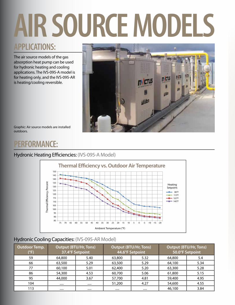
AIR SOURCE MODELSAPPLICATIONS: The air source models of the gas absorption heat pump can be used for hydronic heating and cooling applications. The IVS-095-A model is for heating only, and the IVS-095-AR is heating/cooling reversible.
Hydronic Cooling Capacities: (IVS-095-AR Model)
Hydronic Heating Efficiencies: (IVS-095-A Model)
PERFORMANCE:
75 70 65 60 55 50 45 40 35 30 25 20 15 10 5 0 -5 -10 -15 -20
150
145
140
135
130
125
120
115
110
105
100
95
90
85
Ambient Temperature (°F)
Ther
mal
E�
cien
cy, P
erce
nt HeatingSetpoint:
86°F113°F122°F140°F
Thermal E�ciency vs. Outdoor Air Temperature
Outdoor Temp.(°f)
Output (bTu/hr, Tons)37.4°f setpoint
Output (bTu/hr, Tons)44.6°f setpoint
Output (bTu/hr, Tons)50.0°f setpoint
59 64,800 5.40 63,800 5.32 64,800 5.466 63,500 5.29 63,500 5.29 64,100 5.3477 60,100 5.01 62,400 5.20 63,300 5.2886 54,300 4.53 60,700 5.06 61,800 5.1595 44,000 3.67 57,700 4.81 59,400 4.95
104 ..... ..... 51,200 4.27 54,600 4.55113 ..... ..... ..... ..... 46,100 3.84
Graphic: Air source models are installed outdoors.
ELECTRICCHILLER
(O�)
HEAT PUMP BOILER
HEATLOAD
Out
side
Wal
l
OU
TDO
ORS
IND
OO
RS
SYSTEMPUMP
ELECTRICCHILLER
COOLINGLOAD
Out
side
Wal
l
OU
TDO
ORS
IND
OO
RS
(O�)
HEAT PUMP BOILER
SYSTEMPUMP
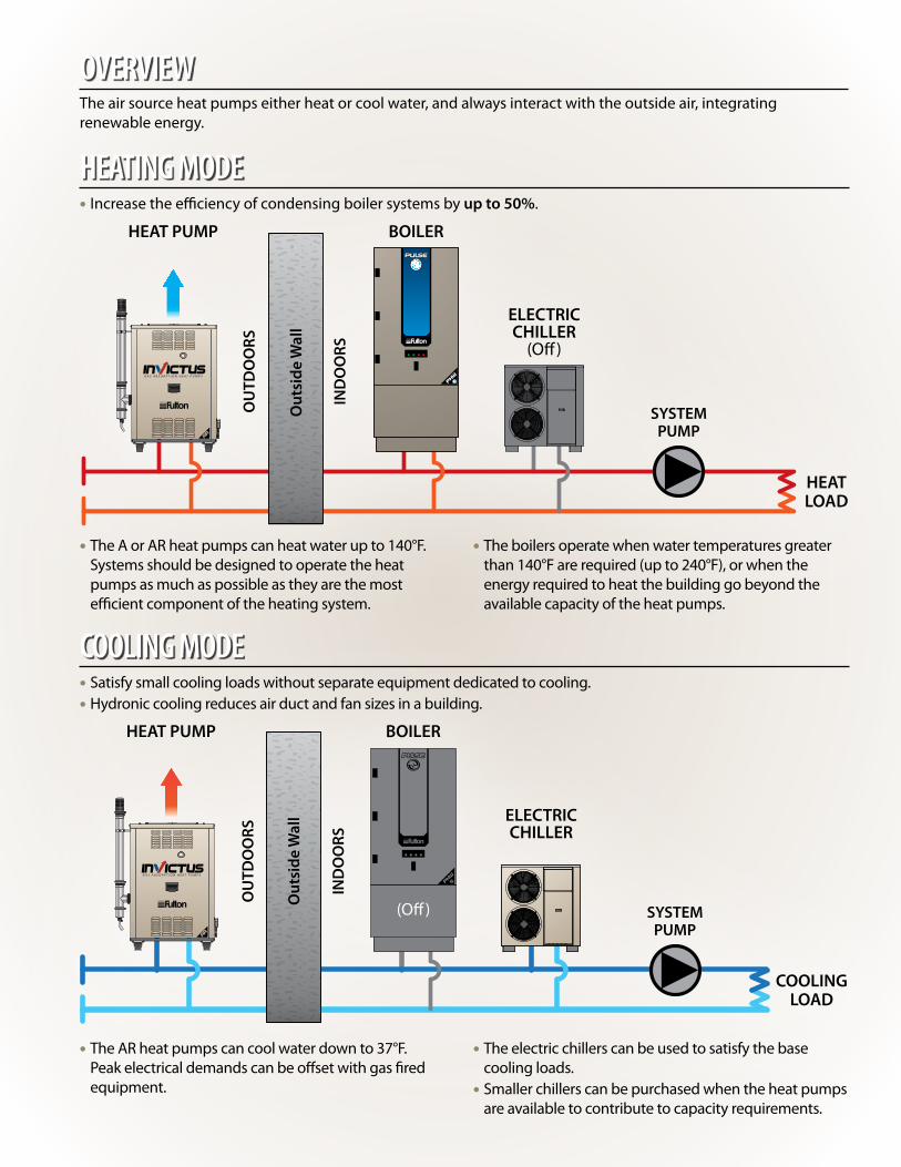
• The A or AR heat pumps can heat water up to 140°F. Systems should be designed to operate the heat pumps as much as possible as they are the most efficient component of the heating system.
• The AR heat pumps can cool water down to 37°F. Peak electrical demands can be offset with gas fired equipment.
• The boilers operate when water temperatures greater than 140°F are required (up to 240°F), or when the energy required to heat the building go beyond the available capacity of the heat pumps.
• The electric chillers can be used to satisfy the base cooling loads.• Smaller chillers can be purchased when the heat pumps are available to contribute to capacity requirements.
• Increase the efficiency of condensing boiler systems by up to 50%.
• Satisfy small cooling loads without separate equipment dedicated to cooling.• Hydronic cooling reduces air duct and fan sizes in a building.
HEATING MODE
COOLING MODE
The air source heat pumps either heat or cool water, and always interact with the outside air, integrating renewable energy.
OVERVIEW

hot Water circuit Temperaturechilled Water
Inlet Temp.95°f circuit
setpoint104°f circuit
setpoint113°f circuit
setpoint122°f circuit
setpoint140°f circuit
setpoint(°f) bTu/hr Tons bTu/hr Tons bTu/hr Tons bTu/hr Tons bTu/hr Tons32 55,900 4.66 53,900 4.49 50,500 4.21 46100 3.48 37600 3.1341 57,400 4.78 56,000 4.67 53,500 4.46 49,800 4.15 43,100 3.5950 58,200 4.85 57,300 4.78 55,800 4.65 53,300 4.44 48,000 4.0059 58,400 4.87 58,000 4.83 57,100 4.76 55,600 4.63 52,000 4.3368 58,400 4.87 58,100 4.84 57,500 4.79 56,600 4.72 54,800 4.5777 59,400 4.87 58,100 4.84 57,500 4.79 56,700 4.73 56,000 4.67
WATER/GROUND SOURCE MODELSAPPLICATIONS: The water/ground source heat pump can be used for hydronic heating and cooling applications. The IVS-095-W model is for water source applications and the IVS-095-WLB is for ground source applications.
Hydronic Cooling Capacities: (IVS-095-W Model)
Graphic: Ground source models are installed indoors.
Hydronic Heating Efficiencies: (IVS-095-W Model)
PERFORMANCE:
85 80 75 70 65 60 55 50 45 40 35 30
150
145
140
135
130
125
120
Source Temperature (°F)
Ther
mal
E�
cien
cy, P
erce
nt
95°F104°F113°F122°F131°F149°F
Thermal E�ciency vs. Source Temperature
HeatingSetpoint:
To Well Field To Heat Users
Return From Wells Return From Users
To Well FieldTo Cooling Users
Return From WellsReturn From Users
To Heat Users
Return From Users
To Cooling Users
Return From Users

Commercial heating and cooling systems can be designed so the water/ground source heat pumps work with boilers, chillers or other technologies to manage load requirements.
• The W and WLB units simultaneously heat and cool water.
OVERVIEW
Gas absorption heat pumps require approximately 40% reduced size well field compared to an electric heat pump system of similar capacity. This provides substantial savings in the up front capital investment associated with this infrastructure.
WELL FIELD REQUIREMENTS
To Well Field To Heat Users
Return From Wells Return From Users
HEATING MODE
• Cold water is directed out to the well field.
• Hot water is directed to the heat users in the building.
To Well FieldTo Cooling Users
Return From WellsReturn From Users
COOLING MODE
• Cold water is directed to the cooling users in the building.
• Hot water is directed out to the well field.
To Heat Users
Return From Users
To Cooling Users
Return From Users
Example: Provide space heat for a building in the winter, simultaneously provide space cooling for a small load, such as an IT server room.
Example: Provide space cooling for areas on the south side of a building; provide space heating for areas on the north side of a building.
HEATING/COOLING SIMULTANEOUSLY• Instead of using the well field, it is possible to use both the hot and cold water for simultaneous applications.

Fulton Heating Solutions, Inc.972 Centerville Road, Pulaski, NY 13142Call: (315) 298-5121 • Fax: (315) 298-6390
www.fulton.com
invictus-bro-2012-1206
The heat transfer innovators.
A and AR ModelRight Side View
A and AR ModelFront View
27 3/8” (*)
10 1/2”
38 1/2” (*)
48 1/2”
50 1 /2” 50
3 /4 ” 60 7 /8 ”
5 7/8”
33 1/2”
4”
33"
E
W and WLB ModelLeft Side View
W and WLB ModelFront View
37 13/16”
33 1/2”
50 3 /4”
51 9 /16
”
25 3/4”
10 1/2”
SPECIFICATIONSAND DIMENSIONS
specifications:
EnERgy sOuRcE aIR sOuRcE WaTER / gROunD sOuRcEmODEl IVs-095-a IVs-095-aR IVs-095-W IVs-095-WlbDimensions:
Width IN 33.5 33.5 33.5 33.5Length IN 48.5 48.5 25.75 25.75Height IN 50.75 50.75 50.75 50.75
Application Heating Only Heat / Cool Reversible Heat / Cool Simultaneous Heat / Cool SimultaneousEnvironmental Component Outdoor Air Outdoor Air Water (Lake / Pond) GroundInput BTU/Hr 95,500 95,500 95,500 95,500Max Output Heat BTU/Hr 139,200 134,800 142,600 133,800Max Efficiency % 146 141 149 140Max Output Cool BTU/Hr (Tons) N/A 64,800 (5.4) 59,400 (4.9) 58,400 (4.9) Max Hot Water Temp °F 140 140 149 140Min Cold Water Temp °F 37 37 37 37Max Ambient Op. Temp °F 113 113 113 113Min Ambient Op. Temp °F -20 -20 10 10Electrical Rating V/Ph/Hz 208-230/1/60 208-230/1/60 208-230/1/60 208-230/1/60Electrical Consumption kW 0.75 0.75 0.4 0.4