hydraulic fluids and lubricants ti rev-g 11-2003
TRANSCRIPT
8/8/2019 Hydraulic Fluids and Lubricants TI Rev-G 11-2003
http://slidepdf.com/reader/full/hydraulic-fluids-and-lubricants-ti-rev-g-11-2003 1/48
Hydraulic Fluids
and Lubricants
Technical
Information
Bac
8/8/2019 Hydraulic Fluids and Lubricants TI Rev-G 11-2003
http://slidepdf.com/reader/full/hydraulic-fluids-and-lubricants-ti-rev-g-11-2003 2/48
2DKMH.PN.980.A2.02 520L0463 Rev.G – 11/2003
Hydraulic Fluids and Lubricants
Technical Information
The purpose of this manual is to aid the machine operator in the selection of suitable
hydraulic uid, gear lubricants, gear bearing grease, preservation uid and petroleum
jelly.
The specications of the lubricant manufacturer and the recommendations of the machine
manufacturer are the basis for selection and are subject to change without advance
advice. The choice of suitable hydraulic uids or lubricants is critical for the lifetime,
operational safety and efciency of hydrostatic components and gears.
If there are any re hazards, see Safety instructions.
The selection of the appropriate hydraulic uid or gear lubricant for a specic application
can be made only when the different features of the lubricants and the task and condi-
tions under which the machine is to operate are taken into consideration.
Content subject to change.
Introduction
INTRODUCTION
© 2003, Sauer-Danfoss. All rights reserved. Printed in Europe.
Sauer-Danfoss accepts no responsibility for possible errors in catalogs, brochures and other printed material.
Sauer -Danfoss reserves the right to alter its products without prior notice. This also applies to products already
ordered provided that such alterations can be made without affecting agreed specications. All trademarks
in this material are properties of their respective owners. Sauer-Danfoss and the Sauer-Danfoss logotype are
trademarks of the Sauer-Danfoss Group.
Front cover illustrations: P001 945, P001 946, P001 944, P001 356.
Bac
8/8/2019 Hydraulic Fluids and Lubricants TI Rev-G 11-2003
http://slidepdf.com/reader/full/hydraulic-fluids-and-lubricants-ti-rev-g-11-2003 3/48
3DKMH.PN.980.A2.02 520L0463 Rev.G – 11/2003
Hydraulic Fluids and Lubricants
Technical Information
SAFETY INSTRUCTIONS
HYDRAULIC FLUIDS –
GENERAL INFORMATION
REQUIREMENTS FOR
HYDRAULIC FLUIDS
SUITABLE HYDRAULIC
FLUIDS
SUITABLE MINERAL
BASED HYDRAULIC
FLUIDS
Contents
Health, accident and environmental measures.................................................................................. 6
Hydraulic Fluid Features ............................................................................................................................. 7
Necessary characteristics of hydraulic uid ................................................................................... 7
Viscosity ...................................................................................................................................................... 8
Conversion of viscosities.................................................................................................................. 8
Viscosity Index (VI) .................................................................................................................................. 9
Shear stability..........................................................................................................................................10
Pour point.................................................................................................................................................10
Density.......................................................................................................................................................10
Sealing compatibility............................................................................................................................10
Air in the hydraulic uid ......................................................................................................................11
Air release............................................................................................................................................11
Foaming characteristic ...................................................................................................................11
Bulk modulus/Compressibility..........................................................................................................12
Calculation..........................................................................................................................................13
Cleanliness Features...................................................................................................................................14
Denition of cleanliness levels per ISO 4406 ...............................................................................14
New particle size denition................................................................................................................16
Recommendation for lter neness/retaining rates (Beta-ratios) .......................................16
Technical Requirements of Hydraulic Fluids......................................................................................17
Water content per DIN ISO 3733 ......................................................................................................17
Air content................................................................................................................................................17
Fluid change intervals ..........................................................................................................................17
Traces of wear metals and contamination....................................................................................18Fluid cleanliness requirements .........................................................................................................18
Viscosity and temperature limits .....................................................................................................20
General............................................................................................................................................................21
Requirenents for Mineral Based Hydraulic Fluids............................................................................21
The following hydraulic uids are suitable: ..................................................................................21
Hydraulic uid according to DIN 51 524-2 HLP, Viscosity–Temperature Diagram ...............22
Hydraulic Fluid according DIN 51 524-3 HVLP, Viscosity–Temperature Diagram .................23
Automatic transmission Fluids (ATF) Typ A SUFFIX A (GM),Viscosity–Temperature Diagram ...........................................................................................................24
Automatic transmission Fluids (ATF) DEXRON II (GM),
Viscosity – Temperature Diagram..........................................................................................................25
Automatic Transmission Fluids (ATF) M2C33F/G, FORD,
Viscosity – Temperature Diagram..........................................................................................................26
Engine oil per API classication SL, SJ, CI-4, CH-4, CG-4, CF-4 and CF,
Viscosity – Temperature Diagram..........................................................................................................27
Multi Purpose Oil STOU - Super Tractor Oil Universal,
Viscosity – Temperature Diagram..........................................................................................................28
Bac
8/8/2019 Hydraulic Fluids and Lubricants TI Rev-G 11-2003
http://slidepdf.com/reader/full/hydraulic-fluids-and-lubricants-ti-rev-g-11-2003 4/48
4DKMH.PN.980.A2.02 520L0463 Rev.G – 11/2003
Hydraulic Fluids and Lubricants
Technical Information
Contents
FIRE RESISTANT
HYDRAULIC FLUIDS
BIODEGRADABLE
HYDRAULIC FLUIDS
Fire Resistant Hydraulic Fluids according to DIN 24 317, DIN 24 320,
VDMA 24 317, and ISO 12 922.................................................................................................................29
HFA uids–oil-in-water emulsions according to DIN 24 320 and ISO 12 922. .................29HFB uids–water-in-oil emulsions according to VDMA 24 317 and ISO 12 922. ............29
HFC uids–watery polymer solutions or water glycols according to VDMA 24 317
and ISO 12 922. ......................................................................................................................................29
HFD uids–water free, synthetic uids according to VDMA 24 317 and ISO 12 922. ...30
Fluid conversion................................................................................................................................30
Requirements for Fire Resistant Hydraulic Fluids ............................................................................31
General operating parameters for re resistant hydraulic uids..........................................31
Specic operating parameters for products running with re resistant uids ...............31
Gear pumps and gear motors:.....................................................................................................31
Fluid change intervals:....................................................................................................................31
Operating parameters..........................................................................................................................32
Proportional valves..........................................................................................................................32
Steering units.....................................................................................................................................32
Biodegradable hydraulic uids according to VDMA 24 568 and ISO/CD 15 380 .................33
HETG – Triglyceride hydraulic uids ................................................................................................34
Operating data ..................................................................................................................................34
Fluid change interval:......................................................................................................................34
Hints for transition ...........................................................................................................................34
Requirements for biodegradable hydraulic uids HETG .........................................................34
HEPG – Poly glycol hydraulic uids .................................................................................................35
Operating data ..................................................................................................................................35
Hints for transition ..........................................................................................................................35
Requirements for biodegradable hydraulic uids HEPG .........................................................35HEES – Synthetic ester based hydraulic uids.............................................................................36
Fluid characteristics.........................................................................................................................36
Operating data ..................................................................................................................................36
Hints for transition ...........................................................................................................................36
Requirements for biodegradable hydraulic uids HEES..........................................................36
HEPR - Polyalphaolens and related hydrocarbon hydraulic uids ....................................37
Fluid characteristics.........................................................................................................................37
Operating data ..................................................................................................................................37
Hints for transition ...........................................................................................................................37
Requirements for biodegradable hydraulic uids HEPR .........................................................37
Biodegradable Hydraulic Fluids, Viscosity – Temperature Diagram.........................................38
Bac
8/8/2019 Hydraulic Fluids and Lubricants TI Rev-G 11-2003
http://slidepdf.com/reader/full/hydraulic-fluids-and-lubricants-ti-rev-g-11-2003 5/48
5DKMH.PN.980.A2.02 520L0463 Rev.G – 11/2003
Hydraulic Fluids and Lubricants
Technical Information
Contents
GEAR LUBRICANTS
GEAR BEARING GREASE
PRESERVATION FLUIDS
PRESERVATION FLUID,
PETROLEUM JELLY
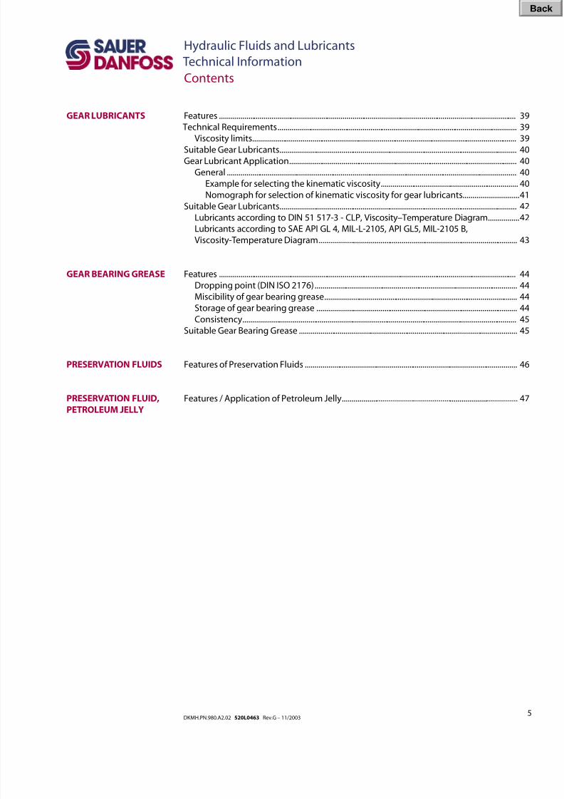
Features ..........................................................................................................................................................39
Technical Requirements............................................................................................................................39
Viscosity limits.........................................................................................................................................39Suitable Gear Lubricants...........................................................................................................................40
Gear Lubricant Application......................................................................................................................40
General ......................................................................................................................................................40
Example for selecting the kinematic viscosity.......................................................................40
Nomograph for selection of kinematic viscosity for gear lubricants.............................41
Suitable Gear Lubricants...........................................................................................................................42
Lubricants according to DIN 51 517-3 - CLP, Viscosity–Temperature Diagram................42
Lubricants according to SAE API GL 4, MIL-L-2105, API GL5, MIL-2105 B,
Viscosity-Temperature Diagram.......................................................................................................43
Features ..........................................................................................................................................................44
Dropping point (DIN ISO 2176).........................................................................................................44
Miscibility of gear bearing grease....................................................................................................44
Storage of gear bearing grease ........................................................................................................44
Consistency..............................................................................................................................................45
Suitable Gear Bearing Grease .................................................................................................................45
Features of Preservation Fluids ..............................................................................................................46
Features / Application of Petroleum Jelly...........................................................................................47
Bac
8/8/2019 Hydraulic Fluids and Lubricants TI Rev-G 11-2003
http://slidepdf.com/reader/full/hydraulic-fluids-and-lubricants-ti-rev-g-11-2003 6/48
6DKMH.PN.980.A2.02 520L0463 Rev.G – 11/2003
Hydraulic Fluids and Lubricants
Technical Information
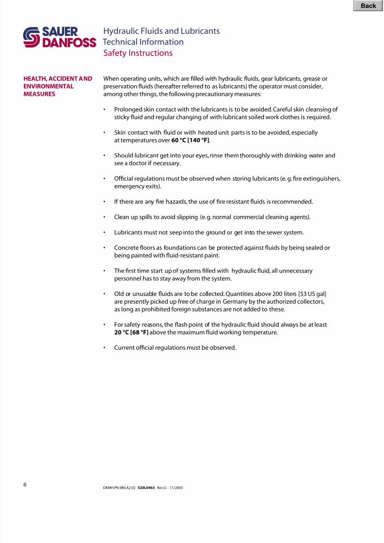
Safety Instructions
When operating units, which are lled with hydraulic uids, gear lubricants, grease or
preservation uids (hereafter referred to as lubricants) the operator must consider,
among other things, the following precautionary measures:
• Prolonged skin contact with the lubricants is to be avoided. Careful skin cleansing of
sticky uid and regular changing of with lubricant soiled work clothes is required.
• Skin contact with uid or with heated unit parts is to be avoided, especially
at temperatures over 60 °C [140 °F].
• Should lubricant get into your eyes, rinse them thoroughly with drinking water and
see a doctor if necessary.
• Ofcial regulations must be observed when storing lubricants (e. g. re extinguishers,
emergency exits).
• If there are any re hazards, the use of re resistant uids is recommended.
• Clean up spills to avoid slipping (e. g. normal commercial cleaning agents).
• Lubricants must not seep into the ground or get into the sewer system.
• Concrete oors as foundations can be protected against uids by being sealed or
being painted with uid-resistant paint.
• The rst time start up of systems lled with hydraulic uid, all unnecessary
personnel has to stay away from the system.
• Old or unusable uids are to be collected. Quantities above 200 liters [53 US gal]
are presently picked up free of charge in Germany by the authorized collectors,
as long as prohibited foreign substances are not added to these.
• For safety reasons, the ash point of the hydraulic uid should always be at least
20 °C [68 °F] above the maximum uid working temperature.
• Current ofcial regulations must be observed.
HEALTH, ACCIDENT AND
ENVIRONMENTAL
MEASURES
Bac
8/8/2019 Hydraulic Fluids and Lubricants TI Rev-G 11-2003
http://slidepdf.com/reader/full/hydraulic-fluids-and-lubricants-ti-rev-g-11-2003 7/48
7DKMH.PN.980.A2.02 520L0463 Rev.G – 11/2003
Hydraulic Fluids and Lubricants
Technical Information
Hydraulic Fluids – General Information
HYDRAULIC FLUID
FEATURES
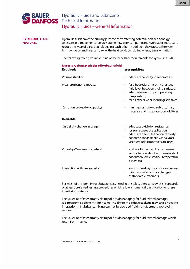
Hydraulic uids have the primary purpose of transferring potential or kinetic energy
(pressure and movements), create volume ow between pump and hydrostatic motor, and
reduce the wear of parts that rub against each other. In addition, they protect the systemfrom corrosion and help carry away the heat produced during energy transformation.
The following table gives an outline of the necessary requirements for hydraulic uids.
Necessary characteristics of hydraulic uid
Required: prerequisites:
Volume stability: • adequate capacity to separate air
Wear protection capacity: • for a hydrodynamic or hydrostatic
uid layer between sliding surfaces;
• adequate viscosity at operating
temperature;
• for all others wear reducing additives
Corrosion protection capacity: • non–aggressive toward customary
materials and rust protection additives
Desirable:
Only slight change in usage: • adequate oxidation resistance;
• for some cases of application
adequate deemulsication capacity;
• adequate shear stability, if polymer
viscosity index improvers are used
Viscosity–Temperature behavior: • so that oil changes due to summer
and winter operation become redundant;
• adequately low Viscosity–Temperature
behaviour
Interaction with Seals/Gaskets • standard sealing materials can be used
• minimal characteristics changes
of standard elastomers
For most of the identifying characteristics listed in the table, there already exist standards
or at least preferred testing procedures which allow a numerical classication of theseidentifying features.
The Sauer-Danfoss warranty claim policies do not apply for uid related damage.
It is not permissible to mix lubricants. The different additive package may cause negative
interactions. If lubricants mixing can not be avoided, uid manufacturers approval is
required.
The Sauer-Danfoss warranty claim policies do not apply for uid related damage which
result from mixing.
Bac
8/8/2019 Hydraulic Fluids and Lubricants TI Rev-G 11-2003
http://slidepdf.com/reader/full/hydraulic-fluids-and-lubricants-ti-rev-g-11-2003 8/48
8DKMH.PN.980.A2.02 520L0463 Rev.G – 11/2003
Hydraulic Fluids and Lubricants
Technical Information
Hydraulic Fluids – General Information
HYDRAULIC FLUID
FEATURES
(continued)
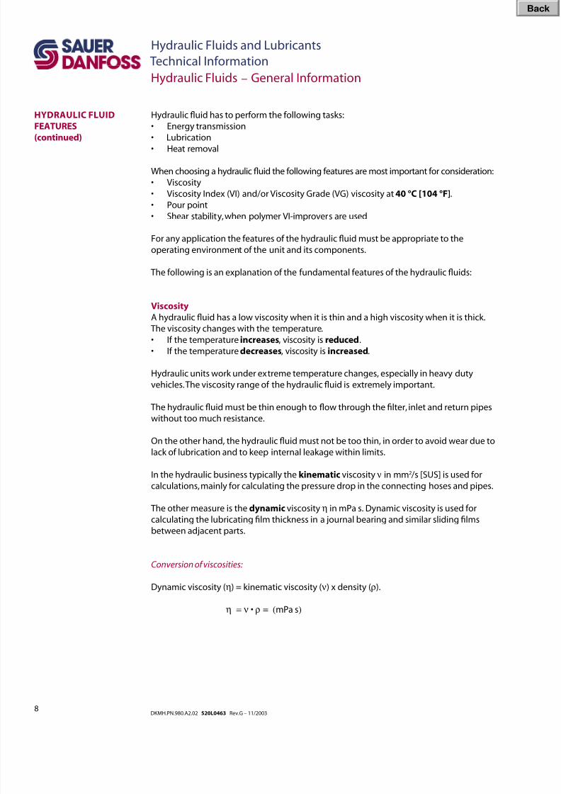
Hydraulic uid has to perform the following tasks:
• Energy transmission
• Lubrication• Heat removal
When choosing a hydraulic uid the following features are most important for consideration:
• Viscosity
• Viscosity Index (VI) and/or Viscosity Grade (VG) viscosity at 40 °C [104 °F].
• Pour point
• Shear stability, when polymer VI-improvers are used
For any application the features of the hydraulic uid must be appropriate to the
operating environment of the unit and its components.
The following is an explanation of the fundamental features of the hydraulic uids:
Viscosity
A hydraulic uid has a low viscosity when it is thin and a high viscosity when it is thick.
The viscosity changes with the temperature.
• If the temperature increases, viscosity is reduced.
• If the temperature decreases, viscosity is increased.
Hydraulic units work under extreme temperature changes, especially in heavy duty
vehicles. The viscosity range of the hydraulic uid is extremely important.
The hydraulic uid must be thin enough to ow through the lter, inlet and return pipes
without too much resistance.
On the other hand, the hydraulic uid must not be too thin, in order to avoid wear due to
lack of lubrication and to keep internal leakage within limits.
In the hydraulic business typically the kinematic viscosity ν in mm2 /s [SUS] is used for
calculations, mainly for calculating the pressure drop in the connecting hoses and pipes.
The other measure is the dynamic viscosity η in mPa s. Dynamic viscosity is used for
calculating the lubricating lm thickness in a journal bearing and similar sliding lms
between adjacent parts.
Conversion of viscosities:
Dynamic viscosity (η) = kinematic viscosity ( ν) x density (ρ).
η = ν • ρ = (mPa s)
Bac
8/8/2019 Hydraulic Fluids and Lubricants TI Rev-G 11-2003
http://slidepdf.com/reader/full/hydraulic-fluids-and-lubricants-ti-rev-g-11-2003 9/48
9DKMH.PN.980.A2.02 520L0463 Rev.G – 11/2003
Hydraulic Fluids and Lubricants
Technical Information
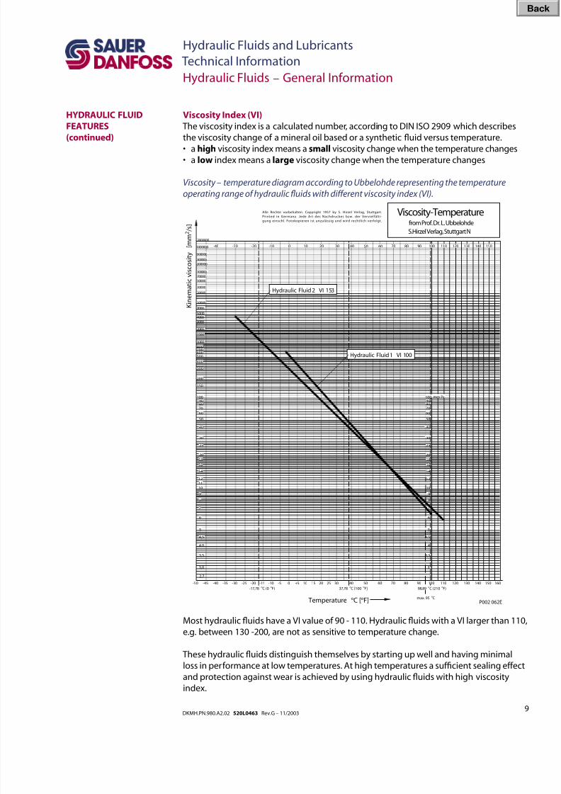
Viscosity Index (VI)
The viscosity index is a calculated number, according to DIN ISO 2909 which describes
the viscosity change of a mineral oil based or a synthetic uid versus temperature.• a high viscosity index means a small viscosity change when the temperature changes
• a low index means a large viscosity change when the temperature changes
Viscosity – temperature diagram according to Ubbelohde representing the temperature
operating range of hydraulic uids with different viscosity index (VI).
Viscosity-Temperaturefrom Prof. Dr. L. Ubbelohde
S.Hirzel Verlag, Stuttgart N
3,0
3,5
4,0
4,5
5
6
7
8
9
101112
14
16
1820
25
30
40
50
60
708090
100
2,7
150
200
300
400
500600700800
1000
1500
2000
3000
40005000
7000
10000
20000
30000
5000070000
100000
200000300000
500000
2000000
-50 -45 -40 -35 -30 -25 -20
-17,78 oC (0 oF)
-15 -10 -5 0 +5 10 15 20 25 30 40
37,78 oC [100 oF]
50 60 70 80 90 100
98,89 oC (210 oF)
110 120 130 140 150 160
3
3,5
4
5
6
7
8
9
10
12
14
16
1820
25
30
40
50
60
708090100
4,5
mm /s2
-40 -30 -20 -10 0 10 20 30 40 50 60 70 80 90 100 110 120 130 140 1501000000
K i n e m a t i c v i s c o s i t y
[ m m 2 / s ]
Temperature oC [oF] max. 95 oC
Alle Rechte vorbehalten. Copyright 1957 by S. Hirzel Verlag, Stuttgart.
Printed in Germany. Jede Art des Nachdruckes bzw. der Vervielfälti-
gung einschl. Fotokopieren ist unzulässig und wird rechtlich verfolgt.
P002 062E
Hydraulic Fluid 2 VI 153
Hydraulic Fluid 1 VI 100
Hydraulic Fluids – General Information
HYDRAULIC FLUID
FEATURES
(continued)
Most hydraulic uids have a VI value of 90 - 110. Hydraulic uids with a VI larger than 110,
e.g. between 130 -200, are not as sensitive to temperature change.
These hydraulic uids distinguish themselves by starting up well and having minimal
loss in performance at low temperatures. At high temperatures a sufcient sealing effect
and protection against wear is achieved by using hydraulic uids with high viscosity
index.
Bac
8/8/2019 Hydraulic Fluids and Lubricants TI Rev-G 11-2003
http://slidepdf.com/reader/full/hydraulic-fluids-and-lubricants-ti-rev-g-11-2003 10/48
10DKMH.PN.980.A2.02 520L0463 Rev.G – 11/2003
Hydraulic Fluids and Lubricants
Technical Information
Hydraulic Fluids – General Information
HYDRAULIC FLUID
FEATURES
(continued)
The high durability of a hydraulic uid with a high viscosity index avoids damage and
machine breakdown, lowers the operating cost and increases the life of hydrostatic
transmissions and units.
Shear stability
Fluids using polymer viscosity index improver may noticeably shear down (> 20 %) in
service. This will lower the viscosity at higher temperatures below the originally specied
value. The lowest expected viscosity must be used when selecting uids. Consult your
uid supplier for details on viscosity shear down.
Pour point
The pour point according to ISO 3016 denes the temperature when the uids stops
to ow. Start up temperature is recommended to be approximately 15 °C [59 °F] above
hydraulic uid pour point.
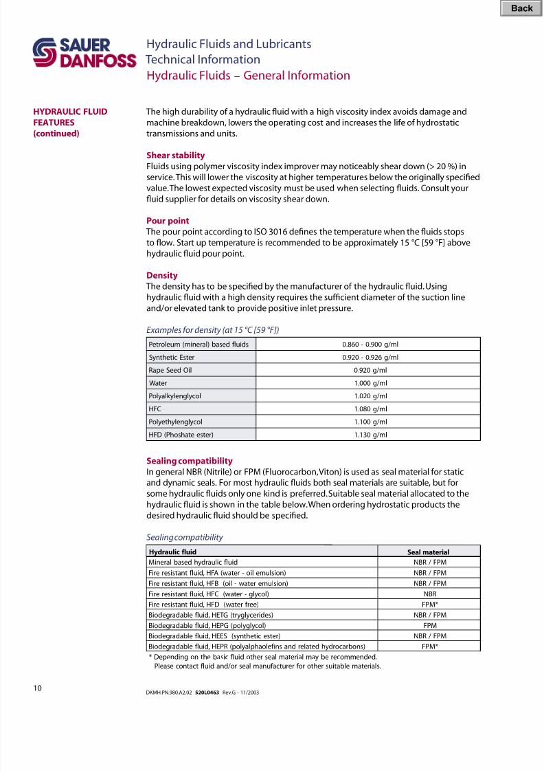
Density
The density has to be specied by the manufacturer of the hydraulic uid. Using
hydraulic uid with a high density requires the sufcient diameter of the suction line
and/or elevated tank to provide positive inlet pressure.
Examples for density (at 15 °C [59 °F])
Sealing compatibility
In general NBR (Nitrile) or FPM (Fluorocarbon, Viton) is used as seal material for static
and dynamic seals. For most hydraulic uids both seal materials are suitable, but for
some hydraulic uids only one kind is preferred. Suitable seal material allocated to the
hydraulic uid is shown in the table below. When ordering hydrostatic products the
desired hydraulic uid should be specied.
Sealing compatibility
sdiulf desab)larenim(muelorteP lm /g0090.-0680.
retsEcitehtnyS lm /g6290.-0290.
liOdeeSepaR lm /g0290.
retaW lm /g0001.
locylgnelyk layloP lm /g0201.
CFH lm /g0801.
locylgnelyhteyloP lm /g0011.
)retseetahsohP(DFH lm /g0311.
diulf ciluardyhdesablareniM MPF /RBN
)noislumelio-retaw(AFH,diulf tnatsisereriF MPF /RBN
)noislumeretaw-lio(BFH,diulf tnatsisereriF MPF /RBN
)locylg-retaw(CFH,diulf tnatsisereriF RBN
)eerf retaw(DFH,diulf tnatsisereriF *MPF
)sedirecylgyrt(G TEH,diulf elbadargedoiB MPF /RBN
)locylgylop(GPEH,diulf elbadargedoiB MPF
)retsecitehtnys(SEEH,diulf elbadargedoiB MPF /RBN
)snobracordyhdetalerdnasnif eloahplaylop(RPEH,diulf elbadargedoiB *MPF
.dednemmocerebyamlairetamlaesrehtodiulf cisabehtnognidnepeD*
.slairetamelbatiusrehtorof rerutcaf unamlaesro /dnadiulf tcatnocesaelP
Seal materialHydraulic fluid
Bac
8/8/2019 Hydraulic Fluids and Lubricants TI Rev-G 11-2003
http://slidepdf.com/reader/full/hydraulic-fluids-and-lubricants-ti-rev-g-11-2003 11/48
11DKMH.PN.980.A2.02 520L0463 Rev.G – 11/2003
Hydraulic Fluids and Lubricants
Technical Information
Air in the hydraulic uid
Free air is considered as contamination as well. Air typically enters the circuit through the
suction line if the seals and ttings are not tight. This free air then may be dissolved inthe hydraulic uid. Mineral based hydraulic uid may contain up to 9 % volume percent
dissolved air at atmospheric pressure. If 1 l [0.264 US gal] of hydraulic uid is compressed
to 100 bar [1450 psi], it may dissolve 9 l [2.377 US gal] of free air if offered.
This is not a problem unless the pressure drops down quickly to a lower level. Then the
air becomes free again and bubbles show up. These bubbles collapse when subjected
to pressure, which results in cavitation which causes erosion of the adjacent material.
Because of this, the greater the air content within the oil, and the greater the vacuum in
the inlet line, the more severe will be the resultant erosion. The bubbles may also result
in a spongy system, slow response time, and poor controllability. Therefore care must be
taken to avoid air to enter the system. If air has entered a system the air release time and
foam characteristic becomes important.
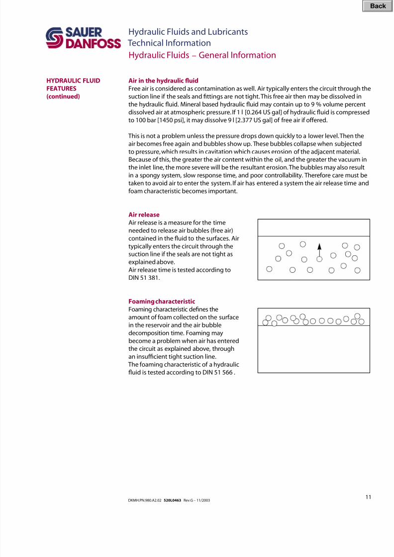
Air release
Air release is a measure for the time
needed to release air bubbles (free air)
contained in the uid to the surfaces. Air
typically enters the circuit through the
suction line if the seals are not tight as
explained above.
Air release time is tested according to
DIN 51 381.
Foaming characteristic
Foaming characteristic denes the
amount of foam collected on the surface
in the reservoir and the air bubble
decomposition time. Foaming may
become a problem when air has entered
the circuit as explained above, through
an insufcient tight suction line.
The foaming characteristic of a hydraulic
uid is tested according to DIN 51 566 .
Hydraulic Fluids – General Information
HYDRAULIC FLUID
FEATURES
(continued)
Bac
8/8/2019 Hydraulic Fluids and Lubricants TI Rev-G 11-2003
http://slidepdf.com/reader/full/hydraulic-fluids-and-lubricants-ti-rev-g-11-2003 12/48
12DKMH.PN.980.A2.02 520L0463 Rev.G – 11/2003
Hydraulic Fluids and Lubricants
Technical Information
Hydraulic Fluids – General Information
HYDRAULIC FLUID
FEATURES
(continued)
Bulk modulus/Compressibility
While uids are usually considered incompressible, the pressures that can occur in
hydrostatic systems are of a magnitude that uid compressibility can be signicant.In applications that experience system pressure uctuations resulting in random high
pressure rise rates, consideration must be given to uid compressibility when sizing a
charge pump to ensure adequate charge pressure.
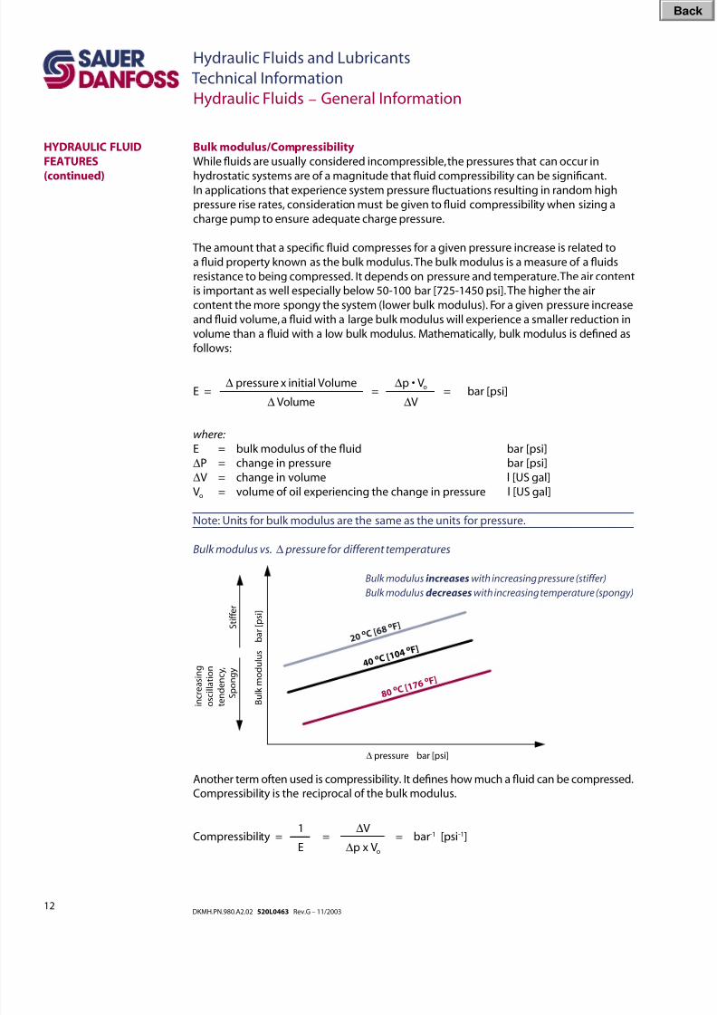
The amount that a specic uid compresses for a given pressure increase is related to
a uid property known as the bulk modulus. The bulk modulus is a measure of a uids
resistance to being compressed. It depends on pressure and temperature. The air content
is important as well especially below 50-100 bar [725-1450 psi]. The higher the air
content the more spongy the system (lower bulk modulus). For a given pressure increase
and uid volume, a uid with a large bulk modulus will experience a smaller reduction in
volume than a uid with a low bulk modulus. Mathematically, bulk modulus is dened as
follows:
∆ pressure x initial Volume ∆p • VoE = = = bar [psi]
∆ Volume ∆V
where:
E = bulk modulus of the uid bar [psi]
∆P = change in pressure bar [psi]
∆V = change in volume l [US gal]
Vo = volume of oil experiencing the change in pressure l [US gal]
Note: Units for bulk modulus are the same as the units for pressure.
Bulk modulus vs. ∆ pressure for different temperatures
Bulk modulus increases with increasing pressure (stiffer)
Bulk modulus decreases with increasing temperature (spongy)
Another term often used is compressibility. It denes how much a uid can be compressed.
Compressibility is the reciprocal of the bulk modulus.
1 ∆V
Compressibility = = = bar-1 [psi-1]
E ∆p x Vo
S t i f f e r
B u l k m o d u l u s
b a r [ p s i ]
i n c r e a s i n g
o s c i l l a t i o n
t e n d e n c y ,
S p o n g y
∆ pressure bar [psi]
2 0 o C [ 6
8 o F ]
4 0 o C [ 1
0 4 o F ]
8 0 o C [ 1
7 6 o F ]
Bac
8/8/2019 Hydraulic Fluids and Lubricants TI Rev-G 11-2003
http://slidepdf.com/reader/full/hydraulic-fluids-and-lubricants-ti-rev-g-11-2003 13/48
13DKMH.PN.980.A2.02 520L0463 Rev.G – 11/2003
Hydraulic Fluids and Lubricants
Technical Information
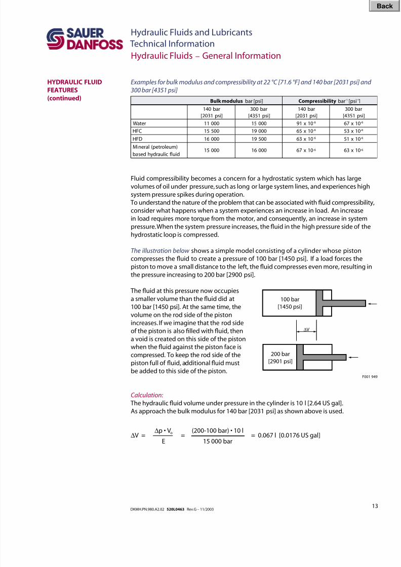
Examples for bulk modulus and compressibility at 22 °C [71.6 °F] and 140 bar [2031 psi] and
300 bar [4351 psi]
Fluid compressibility becomes a concern for a hydrostatic system which has large
volumes of oil under pressure, such as long or large system lines, and experiences high
system pressure spikes during operation.
To understand the nature of the problem that can be associated with uid compressibility,
consider what happens when a system experiences an increase in load. An increase
in load requires more torque from the motor, and consequently, an increase in system
pressure. When the system pressure increases, the uid in the high pressure side of the
hydrostatic loop is compressed.
The illustration below shows a simple model consisting of a cylinder whose piston
compresses the uid to create a pressure of 100 bar [1450 psi]. If a load forces the
piston to move a small distance to the left, the uid compresses even more, resulting in
the pressure increasing to 200 bar [2900 psi].
Hydraulic Fluids – General Information
HYDRAULIC FLUID
FEATURES
(continued)
Calculation:
The hydraulic uid volume under pressure in the cylinder is 10 l [2.64 US gal].
As approach the bulk modulus for 140 bar [2031 psi] as shown above is used.
∆p • Vo (200-100 bar) • 10 l
∆V = = = 0.067 l [0.0176 US gal]
E 15 000 bar
100 bar[1450 psi]
200 bar
[2901 psi]
∆V
Bulk modulus bar [psi] Compressibility bar-1 [psi-1]
rab041
]isp1302[
rab003
]isp1534[
rab041
]isp1302[
rab003
]isp1534[
retaW 00011 00051 01x19 6- 01x76 6-
CFH 00551 00091 01x56 6- 01x35 6-
DFH 00061 00591 01x36 6- 01x15 6-
)muelortep(lareniM
diulf ciluardyhdesab00051 00061 01x76 6- 01x36 6-
The uid at this pressure now occupies
a smaller volume than the uid did at100 bar [1450 psi]. At the same time, the
volume on the rod side of the piston
increases. If we imagine that the rod side
of the piston is also lled with uid, then
a void is created on this side of the piston
when the uid against the piston face is
compressed. To keep the rod side of the
piston full of uid, additional uid must
be added to this side of the piston.F001 949
Bac
8/8/2019 Hydraulic Fluids and Lubricants TI Rev-G 11-2003
http://slidepdf.com/reader/full/hydraulic-fluids-and-lubricants-ti-rev-g-11-2003 14/48
14DKMH.PN.980.A2.02 520L0463 Rev.G – 11/2003
Hydraulic Fluids and Lubricants
Technical Information
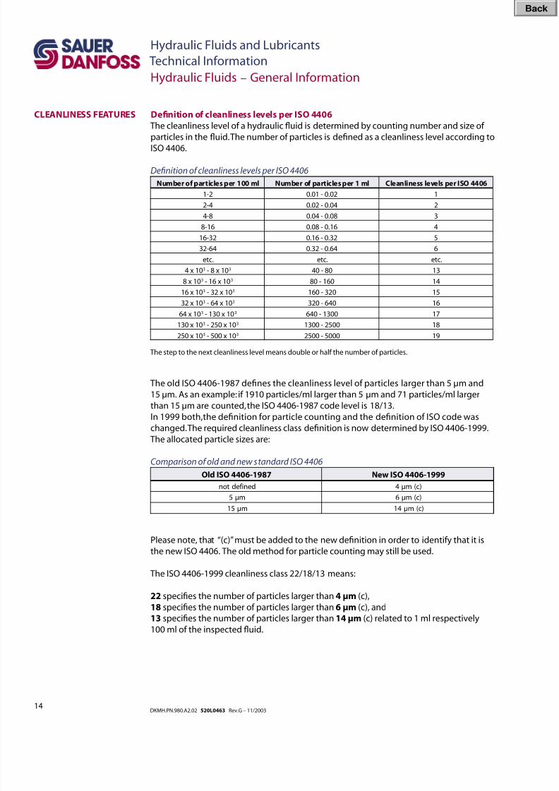
The old ISO 4406-1987 denes the cleanliness level of particles larger than 5 µm and
15 µm. As an example: if 1910 particles/ml larger than 5 µm and 71 particles/ml larger
than 15 µm are counted, the ISO 4406-1987 code level is 18/13.
In 1999 both,the denition for particle counting and the denition of ISO code waschanged. The required cleanliness class denition is now determined by ISO 4406-1999.
The allocated particle sizes are:
Comparison of old and new standard ISO 4406
Please note, that “(c)” must be added to the new denition in order to identify that it is
the new ISO 4406. The old method for particle counting may still be used.
The ISO 4406-1999 cleanliness class 22/18/13 means:
22 species the number of particles larger than 4 µm (c),
18 species the number of particles larger than 6 µm (c), and
13 species the number of particles larger than 14 µm (c) related to 1 ml respectively
100 ml of the inspected uid.
Hydraulic Fluids – General Information
CLEANLINESS FEATURES Denition of cleanliness levels per ISO 4406
The cleanliness level of a hydraulic uid is determined by counting number and size of
particles in the uid. The number of particles is dened as a cleanliness level according toISO 4406.
Denition of cleanliness levels per ISO 4406
Number of particles per 100 ml Number of particles per 1 ml Cleanliness levels per ISO 4406
1-2 0.01 - 0.02 1
2-4 0.02 - 0.04 2
4-8 0.04 - 0.08 3
8-16 0.08 - 0.16 4
16-32 0.16 - 0.32 5
32-64 0.32 - 0.64 6
etc. etc. etc.
4 x 10³ - 8 x 10³ 40 - 80 13
8 x 10³ - 16 x 103 80 - 160 14
16 x 103 - 32 x 103 160 - 320 15
32 x 103 - 64 x 103 320 - 640 16
64 x 103 - 130 x 103 640 - 1300 17
130 x 103 - 250 x 103 1300 - 2500 18
250 x 103 - 500 x 103 2500 - 5000 19
The step to the next cleanliness level means double or half the number of particles.
denif edton )c(mµ4
mµ5 )c(mµ6
mµ51 )c(mµ41
Old ISO 4406-1987 New ISO 4406-1999
Bac
8/8/2019 Hydraulic Fluids and Lubricants TI Rev-G 11-2003
http://slidepdf.com/reader/full/hydraulic-fluids-and-lubricants-ti-rev-g-11-2003 15/48
15DKMH.PN.980.A2.02 520L0463 Rev.G – 11/2003
Hydraulic Fluids and Lubricants
Technical Information
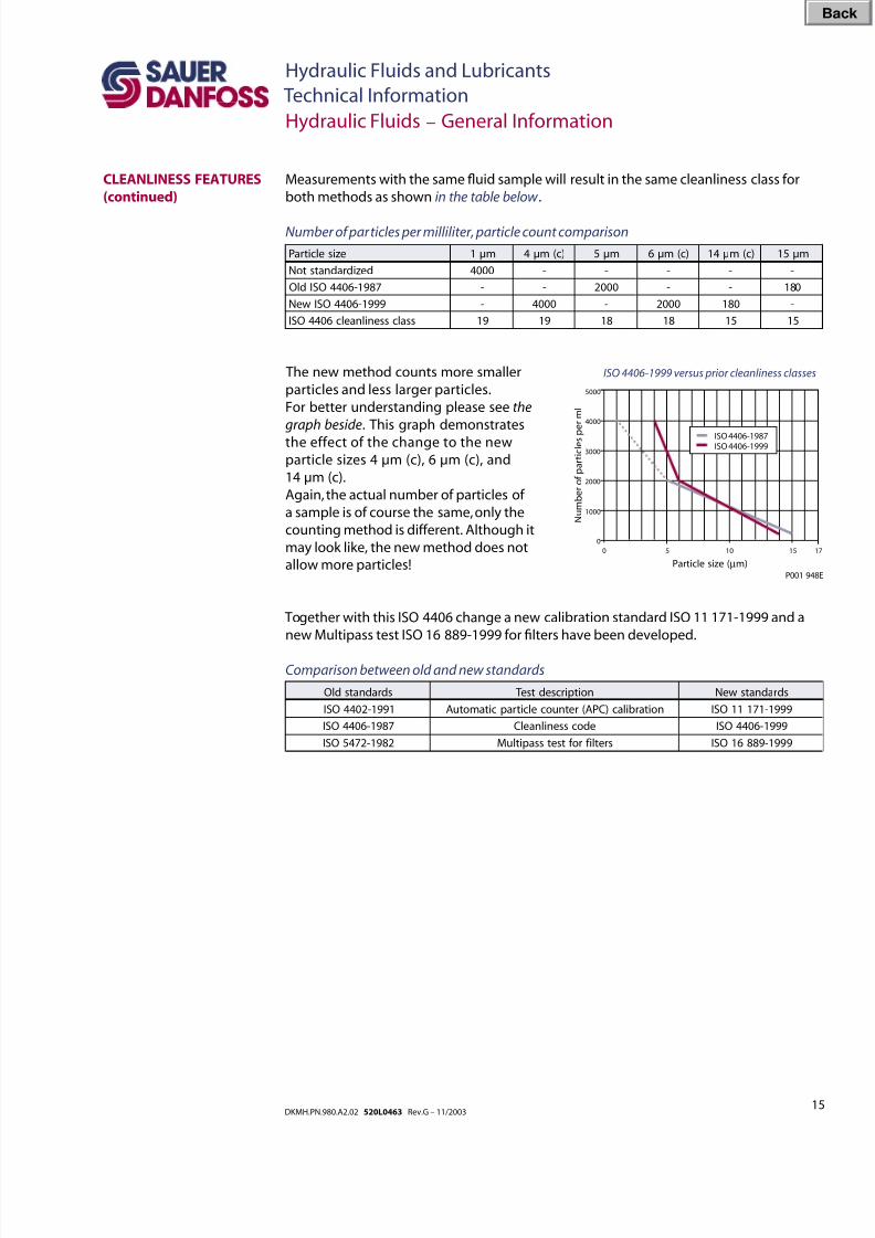
The new method counts more smaller
particles and less larger particles.
For better understanding please see the
graph beside. This graph demonstrates
the effect of the change to the new
particle sizes 4 µm (c), 6 µm (c), and
14 µm (c).
Again, the actual number of particles of
a sample is of course the same, only the
counting method is different. Although it
may look like, the new method does not
allow more particles!
Hydraulic Fluids – General Information
CLEANLINESS FEATURES
(continued)
Measurements with the same uid sample will result in the same cleanliness class for
both methods as shown in the table below .
Number of particles per milliliter, particle count comparison
Together with this ISO 4406 change a new calibration standard ISO 11 171-1999 and a
new Multipass test ISO 16 889-1999 for lters have been developed.
Comparison between old and new standards
ISO 4406-1999 versus prior cleanliness classes
0
0
5 10
1000
2000
3000
4000
5000
15 17
Particle size (µm)
N u m b e r o f p a r t i c l e s p
e r m l
ISO 4406-1987ISO 4406-1999
P001 948E
eziselcitraP mµ1 )c(mµ4 mµ5 )c(mµ6 )c(mµ41 mµ51
dezidradnatstoN 0004 - - - - -
7891-6044OSIdlO - - 0002 - - 081
9991-6044OSIweN - 0004 - 0002 081 -
ssalcssenilnaelc6044OSI 91 91 81 81 51 51
sdradnatsdlO noitpircsedtse T sdradnatsweN
1991-2044OSI noitarbilac)CPA(retnuocelcitrapcitamotuA 9991-17111OSI
7891-6044OSI edocssenilnaelC 9991-6044OSI
2891-2745OSI sretlif rof tsetssapitluM 9991-98861OSI
Bac
8/8/2019 Hydraulic Fluids and Lubricants TI Rev-G 11-2003
http://slidepdf.com/reader/full/hydraulic-fluids-and-lubricants-ti-rev-g-11-2003 16/48
16DKMH.PN.980.A2.02 520L0463 Rev.G – 11/2003
Hydraulic Fluids and Lubricants
Technical Information
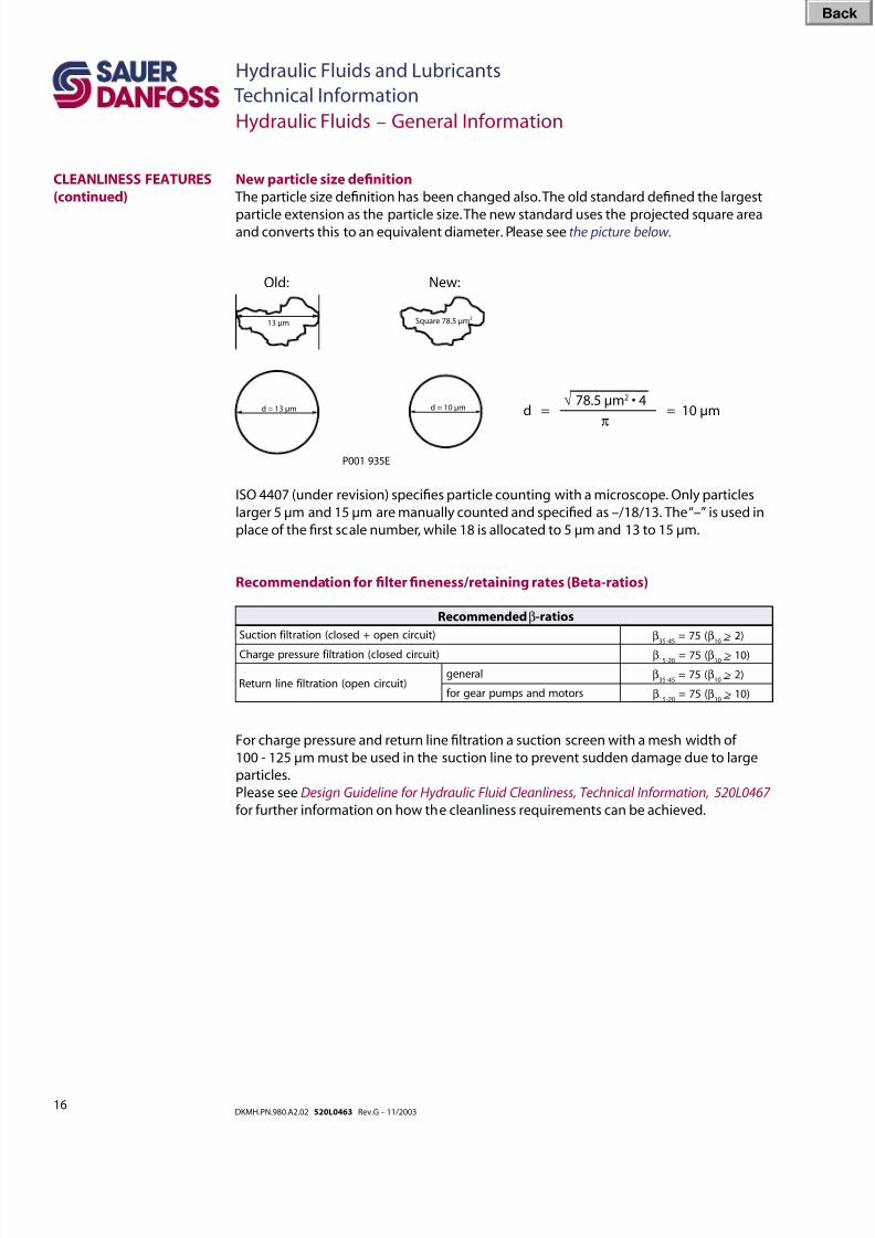
For charge pressure and return line ltration a suction screen with a mesh width of
100 - 125 µm must be used in the suction line to prevent sudden damage due to large
particles.
Please see Design Guideline for Hydraulic Fluid Cleanliness, Technical Information, 520L0467
for further information on how the cleanliness requirements can be achieved.
Recommendation for lter neness/retaining rates (Beta-ratios)
Hydraulic Fluids – General Information
CLEANLINESS FEATURES
(continued)
13 µm
d = 13 µm
Square 78.5 µm2
d = 10 µm
Old: New:
P001 935E
New particle size denition
The particle size denition has been changed also. The old standard dened the largest
particle extension as the particle size. The new standard uses the projected square areaand converts this to an equivalent diameter. Please see the picture below.
√ 78.5 µm2 • 4d = = 10 µm
π
ISO 4407 (under revision) species particle counting with a microscope. Only particles
larger 5 µm and 15 µm are manually counted and specied as –/18/13. The “–” is used in
place of the rst scale number, while 18 is allocated to 5 µm and 13 to 15 µm.
)tiucricnepo+desolc(noitartlif noitcuS β54-53
(57= β01> )2
)tiucricdesolc(noitartlif erusserpegrahC β02-51
(57= β01> )01
)tiucricnepo(noitartlif enilnruteRlareneg β
54-53(57= β
01> )2
srotomdnaspmupraegrof β02-51
(57= β01> )01
Recommendedβ-ratios
Bac
8/8/2019 Hydraulic Fluids and Lubricants TI Rev-G 11-2003
http://slidepdf.com/reader/full/hydraulic-fluids-and-lubricants-ti-rev-g-11-2003 17/48
17DKMH.PN.980.A2.02 520L0463 Rev.G – 11/2003
Hydraulic Fluids and Lubricants
Technical Information
Requirements for Hydraulic Fluids
TECHNICAL
REQUIREMENTS OF
HYDRAULIC FLUIDS
Water content per DIN ISO 3733
In a new uid the water content must be out of the quantitative detectable range.
Unless otherwise specied in individual uid standards the water content for continuousoperation must not exceed 0,1 % (1000 mg/kg). The lower the better. In principle water
is a harmful contaminant, reducing the life of the hydraulic uid and the mechanical
components. Water in a system may result in corrosion, cavitation, and altered uid
viscosity. Depending on the uid, water may also react with the uid to create harmful
chemical by-products or destroy important additives. Left unchecked, water contamination
may result in microbial growth. At this stage, system components may already have been
damaged.
Experiments with a HLP-Oil with a water content of 1 % led to a signicant pressure rise
at the lter, which had as a consequence the destruction of the lter due to swelling and
therefore an increase of the differential pressure.
The water content requirements do not apply for HFA, HFB, HFC–uids.
Air content
Air in a system is also regarded as a contaminant. Air increases the compressibility of the
uid, resulting in a “spongy” system that is less responsive. Also air creates a loss of trans-
mitted power, higher operating temperatures, increased noise levels, and loss of lubricity.
Fluid change intervals
Sauer-Danfoss recommends the following uid change intervals for all uids except
those mentioned below:
First change 500 operating hours after start up
Second and subsequent change every 2000 operating hours or once a year
For HFA, HFB, HFC, HFD and biodegradable hydraulic uids HETG shorter uid change
intervals are recommended:
First change 500 operating hours after start up
Second and subsequent change every 1000 operating hours or once a year
This recommendation applies for most applications. High temperatures and pressures
will result in accelerated uid aging and an earlier uid change may be required.
At lower uid pressure loads longer change intervals are possible. Therefore we suggest
taking a sample of the uid at least one time, preferably more, between scheduled uid
changes. This uid sample then can be sent to the uid manufacturer for an analysis and
a determination of its suitability for continued use.
Bac
8/8/2019 Hydraulic Fluids and Lubricants TI Rev-G 11-2003
http://slidepdf.com/reader/full/hydraulic-fluids-and-lubricants-ti-rev-g-11-2003 18/48
18DKMH.PN.980.A2.02 520L0463 Rev.G – 11/2003
Hydraulic Fluids and Lubricants
Technical Information
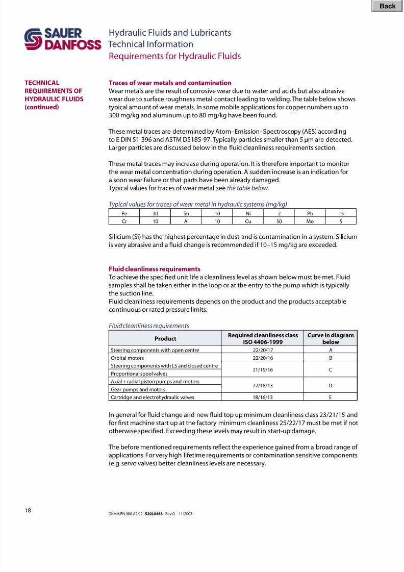
Fluid cleanliness requirements
To achieve the specied unit life a cleanliness level as shown below must be met. Fluid
samples shall be taken either in the loop or at the entry to the pump which is typically
the suction line.
Fluid cleanliness requirements depends on the product and the products acceptablecontinuous or rated pressure limits.
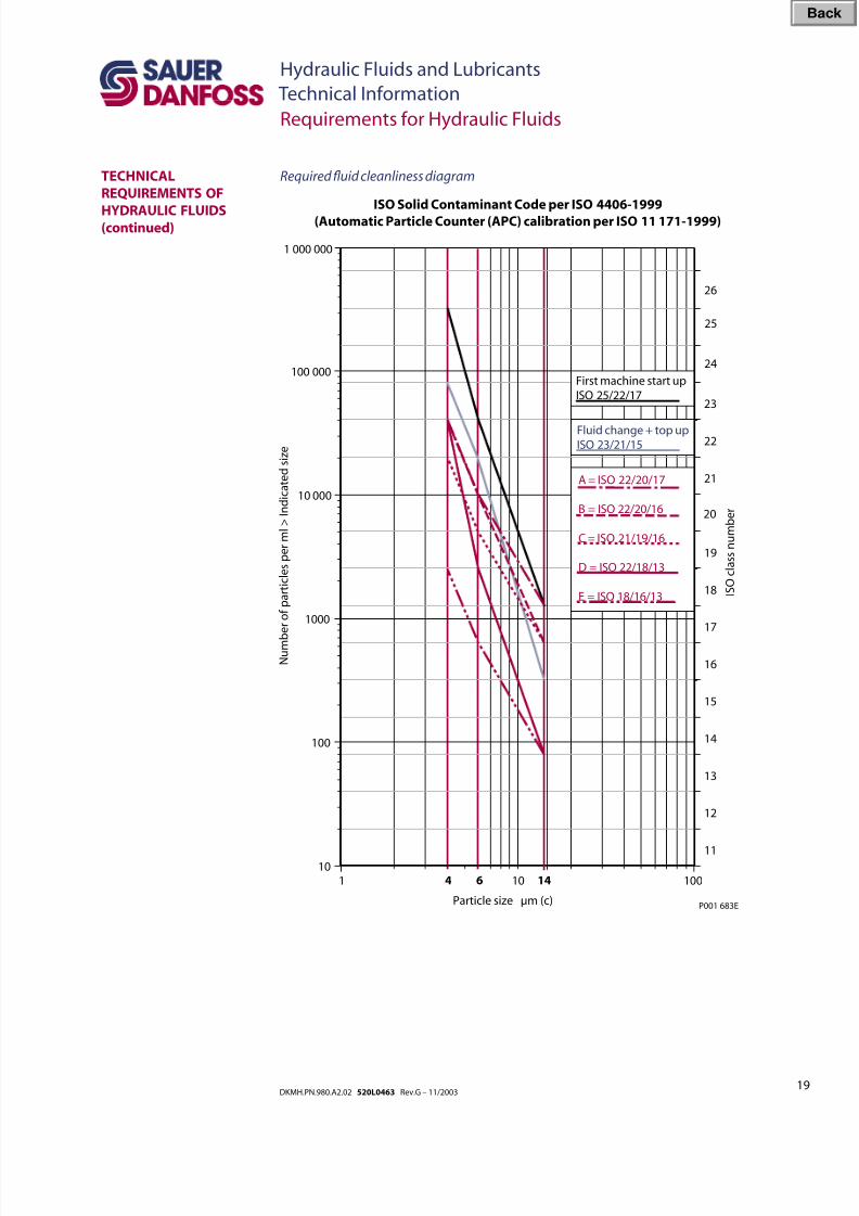
Fluid cleanliness requirements
ProductRequired cleanliness class
ISO 4406-1999Curve in diagram
below
Steering components with open centre 22/20/17 A
Orbital motors 22/20/16 B
Steering components with LS and closed centre21/19/16 C
Proportional spool valves
Axial + radial piston pumps and motors22/18/13 D
Gear pumps and motors
Cartridge and electrohydraulic valves 18/16/13 E
In general for uid change and new uid top up minimum cleanliness class 23/21/15 and
for rst machine start up at the factory minimum cleanliness 25/22/17 must be met if not
otherwise specied. Exceeding these levels may result in start-up damage.
The before mentioned requirements reect the experience gained from a broad range of
applications. For very high lifetime requirements or contamination sensitive components
(e.g. servo valves) better cleanliness levels are necessary.
Requirements for Hydraulic Fluids
Traces of wear metals and contamination
Wear metals are the result of corrosive wear due to water and acids but also abrasive
wear due to surface roughness metal contact leading to welding. The table below showstypical amount of wear metals. In some mobile applications for copper numbers up to
300 mg/kg and aluminum up to 80 mg/kg have been found.
These metal traces are determined by Atom–Emission–Spectroscopy (AES) according
to E DIN 51 396 and ASTM D5185-97. Typically particles smaller than 5 µm are detected.
Larger particles are discussed below in the uid cleanliness requirements section.
These metal traces may increase during operation. It is therefore important to monitor
the wear metal concentration during operation. A sudden increase is an indication for
a soon wear failure or that parts have been already damaged.
Typical values for traces of wear metal see the table below.
Typical values for traces of wear metal in hydraulic systems (mg/kg)
Fe 30 Sn 10 Ni 2 Pb 15
Cr 10 Al 10 Cu 50 Mo 5
Silicium (Si) has the highest percentage in dust and is contamination in a system. Silicium
is very abrasive and a uid change is recommended if 10–15 mg/kg are exceeded.
TECHNICAL
REQUIREMENTS OF
HYDRAULIC FLUIDS(continued)
Bac
8/8/2019 Hydraulic Fluids and Lubricants TI Rev-G 11-2003
http://slidepdf.com/reader/full/hydraulic-fluids-and-lubricants-ti-rev-g-11-2003 19/48
19DKMH.PN.980.A2.02 520L0463 Rev.G – 11/2003
Hydraulic Fluids and Lubricants
Technical Information
Requirements for Hydraulic Fluids
TECHNICAL
REQUIREMENTS OF
HYDRAULIC FLUIDS(continued)
10
100
1000
10 000
100 000
11
12
13
14
15
16
17
18
19
20
21
22
23
1 10 100
N u m b
e r o f p a r t i c l e s p e r m l > I n d i c a t e d s i z e
I S O c l a s s n u m b e r
Particle size µm (c)
4 146
24
25
ISO Solid Contaminant Code per ISO 4406-1999
(Automatic Particle Counter (APC) calibration per ISO 11 171-1999)
1 000 000
26
P001 683E
First machine start upISO 25/22/17
Fluid change + top upISO 23/21/15
A = ISO 22/20/17
B = ISO 22/20/16
C = ISO 21/19/16
D = ISO 22/18/13
E = ISO 18/16/13
Required uid cleanliness diagram
Bac
8/8/2019 Hydraulic Fluids and Lubricants TI Rev-G 11-2003
http://slidepdf.com/reader/full/hydraulic-fluids-and-lubricants-ti-rev-g-11-2003 20/48
20DKMH.PN.980.A2.02 520L0463 Rev.G – 11/2003
Hydraulic Fluids and Lubricants
Technical Information
Requirements for Hydraulic Fluids
TECHNICAL
REQUIREMENTS OF
HYDRAULIC FLUIDS(continued)
Viscosity and temperature limits
When using hydraulic uid the viscosity and temperature limits in the table below are to
be observed. Under normal operating condition it is recommended to keep the temper-ature in the range of 30 °C to 60 °C. Fluid temperature affects the viscosity of the uid and
resulting lubricity and lm thickness. High temperatures can also limit seal life, as most
nonmetallic materials are adversely affected by use at elevated temperatures. Fluids may
break down or oxidize at high temperatures, reducing their lubricity and resulting in
reduced life of the unit.
As a rule of thumb, uid temperature increase from 80 °C [176 °F] to 90 °C [194 °F] may
reduce uid life by 50 %.
Viscosity and temperature limits
Product line
Min. vicosity
(intermittent)
mm2
/s [SUS]
Maximum
temperature
(intermittent)oC [oF]
Recommended
viscosity
mm2
/s [SUS]
Maximum cold
start viscosity
mm2
/s [SUS]
Minimum
temperatureo
C [o
F]
Series 10 7 [48.79] 95 [203]
12-80
[66.03-370.3]
1000 [4629] -40 [-40]
Series 15
Open circuit12 [66.03] 85 [185] 860 [3981] -20 [-4]
Series 20
7 [48.79]
95 [203] 1000 [4629]
-40 [-40]
Series 40 105 [221]1600 [7406]
Series 42 115 [239]
Series 45 9 [55.51] 105 [221] 1000 [4629]
Series 51 7 [48.79] 115 [239]
1600 [7406]
Series 60 9 [55.51] 85 [185] -20 [-4]
Series 90
7 [48.79]115 [239]
-40 [-40] TMP/TMM
LV/LC/KV/KC 105 [221]
Gear pumps and motors 10 [58.91] 80 [176]1000 [4629]
1600 [7406]***-20 [-4]
RMF
(hydrostatic motor only)7 [48.79]
95 [203] 1000 [4629]
-40 [-40]CW 5-8
(hydrostatic motor only)115 [239] 1600 [7406]
Hydrostatic steerings 10 [58.91]90 [194]
1000 [4629]
-30 [-22]
Proportional valves (PVG) 4 [39.17] 460 [2129]
Cartridge valves12 [66.03]
82 [180] 440 [2037]Electrohydraulic valves
Spool valves 6 [45.59]
Orbital motors12 [66.03]*
20 [97.69]**90 [194]
20-80
[97.69-370.3]1500 [6944]
* for OMR, OMH, OMS, OMT, OMV, TMT
** for OML, OMM, OMP
*** for Group 2
Note: Fire resistant uids HFA, HFB, HFC, and biodegradable uids HETG have limited
temperature capabilities. Please see the individual uids information given in this
manual and contact the uid manufacturer.
Bac
8/8/2019 Hydraulic Fluids and Lubricants TI Rev-G 11-2003
http://slidepdf.com/reader/full/hydraulic-fluids-and-lubricants-ti-rev-g-11-2003 21/48
21DKMH.PN.980.A2.02 520L0463 Rev.G – 11/2003
Hydraulic Fluids and Lubricants
Technical Information
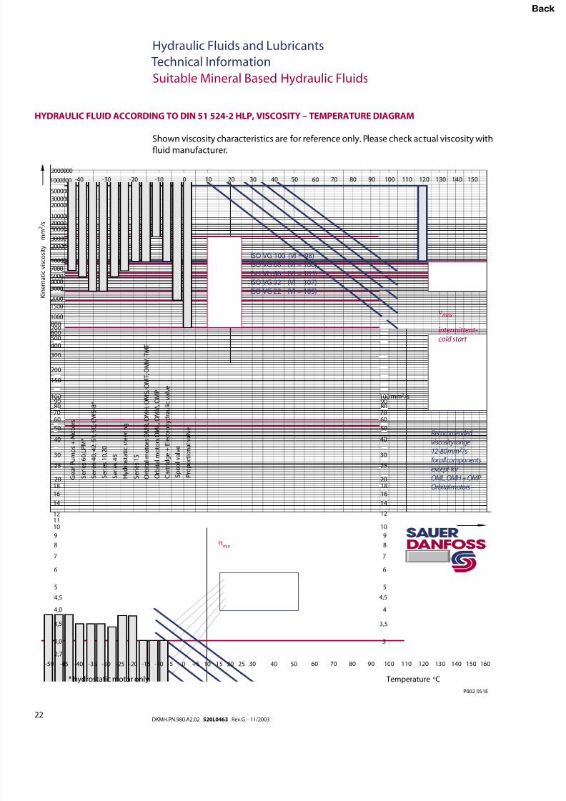
Sauer-Danfoss hydrostatic components may be operated with a variety of hydraulic uids.
The rated data which we publish in our Technical Information and Service Manuals arebased on the use of premium hydraulic uids containing oxidation, rust, and foam inhibi-
tors. These uids must also possess good thermal and hydrolytic stability to prevent wear
erosion, and corrosion of the internal components. For some applications good anti-wear
additives are required.
The following hydraulic uids are suitable:
• Hydraulic Oil ISO 11 158 - HM (Seal compatibility and vane pump wear resistance per
DIN 51 524-2 must be met)
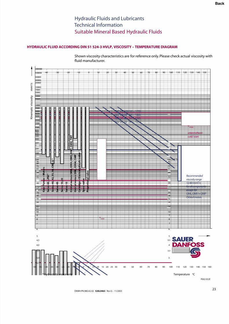
• Hydraulic Oil ISO 11 158 - HV (Seal compatibility and vane pump wear resistance per
DIN 51 524-3 must be met)
• Hydraulic Oil DIN 51 524-2 - HLP
• Hydraulic Oil DIN 51 524-3 - HVLP
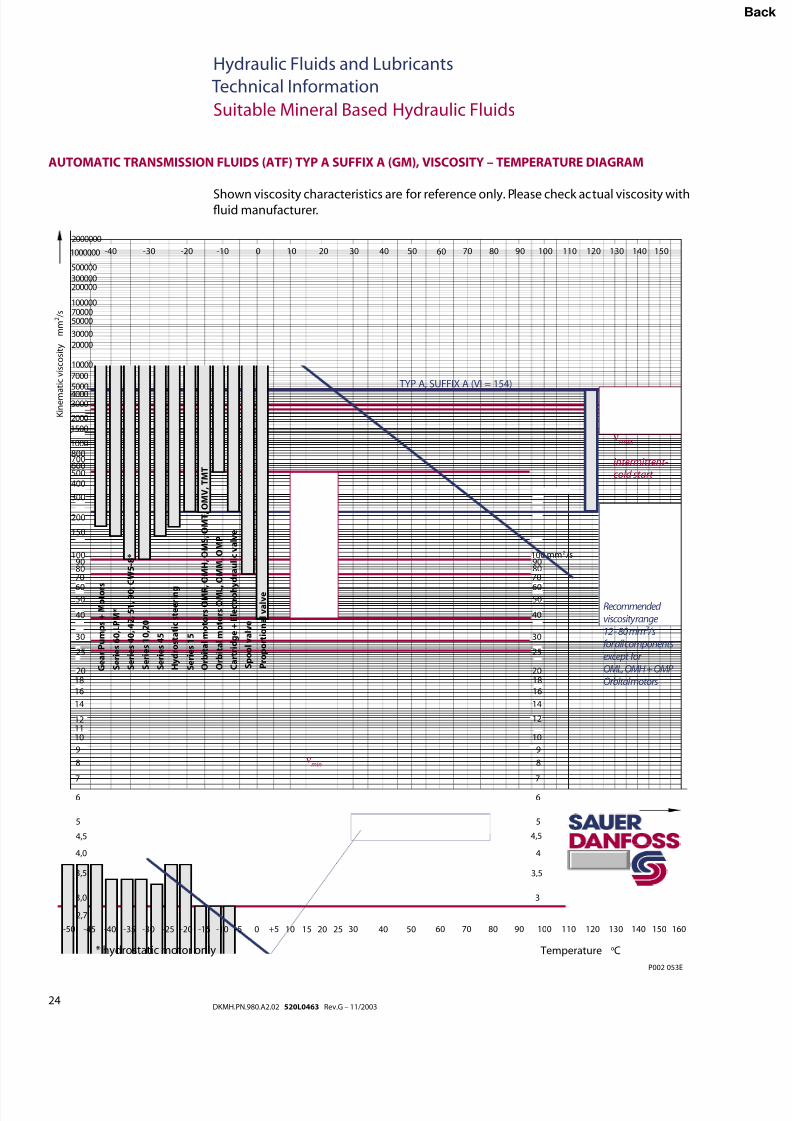
• Automatic Transmission Fluid ATF A Sufx A (GM)
• Automatic Transmission Fluid Dexron II (GM), which meets Allison C-3 and Caterpillar
TO-2 test
• Automatic Transmission Fluid M2C33F and G (Ford)
• Engine oils API Classication SL, SJ (for gasoline engines) and CI-4, CH-4, CG-4, CF-4
and CF (for diesel engines)
• Super Tractor Oil Universal (STOU) special agricultural tractor uid
Contact Sauer-Danfoss and/or follow further mentioned information before using:
• Premium Turbine Oils
• Automatic Transmission Fluid Dexron III (GM)
• Biodegradable hydraulic uids HETG, HEPG, HEES, and HEPR
per VDMA 24 568 and ISO 15 380 meeting Annex B of ISO 15 380– DIN 51 350-6 Taper Roller Bearing Shear Stability test for uids containing
polymers (ISO 20 844 Diesel Injector Nozzle Shear Stability test only for medium
duty applications)
– VDMA 24 570 Yellow Metal Compatibility test
• Fire resistant uids HFA, HFB, HFC, and HFD are suitable at modied operating
parameters, but not with Gear Pumps and Motors.
Fluids meeting these requirements will very likely provide acceptable unit life, but eld
testing is the only truly indication of uid performance.
The Sauer-Danfoss warranty claim policies do not apply for uid related damage.
It is not permissible to mix hydraulic uids. The different additive packages may cause
negative interactions. If hydraulic uid mixing can not be avoided, uid manufacturers
approval is required. The Sauer-Danfoss warranty claim policies do not apply for uid
related damage which result from mixing.
Suitable Hydraulic Fluids
GENERAL
REQUIRENENTS FOR
MINERAL BASED
HYDRAULIC FLUIDS
The requirements concerning water content, Viscosity–Temperature limits, cleanliness
level described in the section Requirements of hydraulic uids must be met.
Bac
8/8/2019 Hydraulic Fluids and Lubricants TI Rev-G 11-2003
http://slidepdf.com/reader/full/hydraulic-fluids-and-lubricants-ti-rev-g-11-2003 22/48
22DKMH.PN.980.A2.02 520L0463 Rev.G – 11/2003
Hydraulic Fluids and Lubricants
Technical Information
Suitable Mineral Based Hydraulic Fluids
HYDRAULIC FLUID ACCORDING TO DIN 51 524-2 HLP, VISCOSITY – TEMPERATURE DIAGRAM
Shown viscosity characteristics are for reference only. Please check actual viscosity withuid manufacturer.
3,0
3,5
4,0
4,5
5
6
7
8
9
101112
14
16
1820
25
30
40
5060
708090
100
2,7
150
200
300
4005006007008001000
15002000
3000400050007000
10000
20000
30000
5000070000100000
200000300000
500000
2000000
-50 -45 -40 -35 -30 -25 -20 -15 -10 -5 0 +5 10 15 20 25 30 40 50 60 70 80 90 100 110 120 130 140 150 160
3
3,5
4
5
6
7
8
9
10
12
14
16
1820
25
30
40
5060
708090100
4,5
mm /s2
-40 -30 -20 -10 0 10 20 30 40 50 60 70 80 90 100 110 120 130 140 1501000000
K i n e m a t i c v i s c o s i t y
m m 2 / s
Recommended viscosity range12-80 mm2 /sfor all componentsexcept for OML, OMH + OMP Orbital motors
νmax
intermittent-cold start
Temperature oC* hydrostatic motor only
P002 051E
ISO VG 100 (VI = 98)ISO VG 68 (VI = 100)ISO VG 46 (VI = 103)
ISO VG 32 (VI = 107)ISO VG 22 (VI = 105)
S e r i e s 1 0 , 2 0
S e r i e s 4 5
S e r i e s 6 0 , L P M *
S e r i e s 1 5
G e a r P u m p s + M o t o r s
H y d r o s t a t i c s t e e r i n g
S e r i e s 4 0 , 4 2 , 5 1 , 9 0 , C
W 5 - 8 *
O r b i t a l m o t o r s O M R , O
M H , O M S , O M T , O M V , T M T
O r b i t a l m o t o r s O M L , O
M M , O M P
C a r t r i d g e + E l e c t r o h y d r a u l i c v a l v e
P r o p o r t i o n a l v a l v e
S p o o l v a l v e
nmin
Bac
8/8/2019 Hydraulic Fluids and Lubricants TI Rev-G 11-2003
http://slidepdf.com/reader/full/hydraulic-fluids-and-lubricants-ti-rev-g-11-2003 23/48
23DKMH.PN.980.A2.02 520L0463 Rev.G – 11/2003
Hydraulic Fluids and Lubricants
Technical Information
Suitable Mineral Based Hydraulic Fluids
Shown viscosity characteristics are for reference only. Please check actual viscosity withuid manufacturer.
HYDRAULIC FLUID ACCORDING DIN 51 524-3 HVLP, VISCOSITY – TEMPERATURE DIAGRAM
K i n e m
a t i c v i s c o s i t y
m m 2 / s
Temperature oC* hydrostatic motor only
3,0
3,5
4,0
4,5
5
6
7
8
9
101112
14
16
1820
25
30
40
50
60
708090
100
2,7
150
200
300
400
500600700800
1000
1500
2000
30004000
5000
7000
10000
20000
30000
50000
70000
100000
200000
300000
500000
2000000
-50 -45 -40 -35 -30 -25 -20 -15 -10 -5 0 +5 10 15 20 25 30 40 50 60 70 80 90 100 110 120 130 140 150 160
3
3,5
4
5
6
7
8
9
10
12
14
16
1820
25
30
40
50
60
708090
100
4,5
mm /s2
-40 -30 -20 -10 0 10 20 30 40 50 60 70 80 90 100 110 120 130 140 1501000000
G e a r P u m p s + M o t o
r s
S e r i e s 1 0 , 2
0
S e r i e s 6 0 ,
L P M *
S e r i e s 4 5
S e r i e s 4 0 ,
4 2 ,
5 1 , 9 0
, C W 5 - 8 *
S e r i e s 1 5
ISO VG 100 (VI = 170)
ISO VG 68 (VI = 180)
ISO VG 46 (VI = 180)
ISO VG 32 (VI = 165)
P002 052E
Recommended
viscosity range
12-80 mm2 /s
for all components
except for
OML, OMH + OMP
Orbital motors
νmax
intermittent-
cold start
O r b i t a l m o t o r s O M R
, O M H ,
O M S ,
O M T ,
O M V ,
T M T
O r b i t a l m o t o r s O M L ,
O M M ,
O M P
C a r t r i d g e + E l e c t r o h y d r a u l i c v a l v e
P r o p o r t i o n a l v a l v e
S p o o l v a l v e
νmin
Bac
8/8/2019 Hydraulic Fluids and Lubricants TI Rev-G 11-2003
http://slidepdf.com/reader/full/hydraulic-fluids-and-lubricants-ti-rev-g-11-2003 24/48
24DKMH.PN.980.A2.02 520L0463 Rev.G – 11/2003
Hydraulic Fluids and Lubricants
Technical Information
Suitable Mineral Based Hydraulic Fluids
AUTOMATIC TRANSMISSION FLUIDS (ATF) TYP A SUFFIX A (GM), VISCOSITY – TEMPERATURE DIAGRAM
Shown viscosity characteristics are for reference only. Please check actual viscosity withuid manufacturer.
3,0
3,5
4,0
4,5
5
6
7
8
9
101112
14
16
1820
25
30
40
5060
708090
100
2,7
150
200
300
4005006007008001000
15002000
3000400050007000
10000
20000
30000
5000070000100000
200000300000
500000
2000000
-50 -45 -40 -35 -30 -25 -20 -15 -10 -5 0 +5 10 15 20 25 30 40 50 60 70 80 90 100 110 120 130 140 150 160
3
3,5
4
5
6
7
8
9
10
12
14
16
1820
25
30
40
5060
708090100
4,5
mm /s2
-40 -30 -20 -10 0 10 20 30 40 50 60 70 80 90 100 110 120 130 140 1501000000
K i n e m a t i c v i s c o s i t y
m m 2 / s
Recommended viscosity range12 - 80 mm2 /sfor all componentsexcept for OML, OMH + OMP Orbital motors
νmax
intermittent-cold start
Temperature oC* hydrostatic motor only
P002 053E
S e r i e s 1 0 , 2
0
S e r i e s 4 5
S e r i e s 6 0 , L
P M *
S e r i e s 1 5
G e a r P u m p s + M o t o r
s
H y d r o s t a t i c s t e e r i n g
S e r i e s 4 0 ,
4 2 ,
5 1 ,
9 0 ,
C W 5 - 8 *
νmin
O r b i t a l m o t o r s O M R
, O M H ,
O M S ,
O M T ,
O M V ,
T M T
O r b i t a l m o t o r s O M L
, O M M ,
O M P
C a r t r i d g e + E l e c t r o h y d r a u l i c v a l v e
S p o o l v a l v e
P r o p o r t i o n a l v a l v e
TYP A, SUFFIX A (VI = 154)
Bac
8/8/2019 Hydraulic Fluids and Lubricants TI Rev-G 11-2003
http://slidepdf.com/reader/full/hydraulic-fluids-and-lubricants-ti-rev-g-11-2003 25/48
25DKMH.PN.980.A2.02 520L0463 Rev.G – 11/2003
Hydraulic Fluids and Lubricants
Technical Information
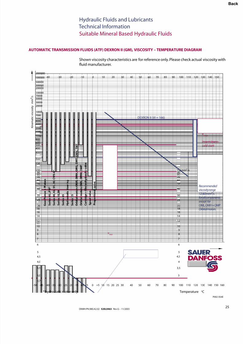
AUTOMATIC TRANSMISSION FLUIDS (ATF) DEXRON II (GM), VISCOSITY – TEMPERATURE DIAGRAM
Suitable Mineral Based Hydraulic Fluids
Shown viscosity characteristics are for reference only. Please check actual viscosity withuid manufacturer.
3,0
3,5
4,0
4,5
5
6
7
8
9
101112
14
16
1820
25
30
40
5060
708090
100
2,7
150
200
300
4005006007008001000
15002000
3000400050007000
10000
20000
30000
5000070000100000
200000300000
500000
2000000
-50 -45 -40 -35 -30 -25 -20 -15 -10 -5 0 +5 10 15 20 25 30 40 50 60 70 80 90 100 110 120 130 140 150 160
3
3,5
4
5
6
7
8
9
10
12
14
16
1820
25
30
40
5060
708090100
4,5
mm /s2
-40 -30 -20 -10 0 10 20 30 40 50 60 70 80 90 100 110 120 130 140 1501000000
K i n e m a t i c v i s c o s i t y
m m 2 / s
Recommended viscosity range12-80 mm2 /sfor all componentsexcept for OML, OMH + OMP Orbital motors
νmax
intermittent-cold start
Temperature oC* hydrostatic motor only
P002 054E
S e r i e s 1 0 , 2
0
S e r i e s 4 5
S e r i e s 6 0 , L
P M *
S e r i e s 1 5
G e a r P u m p s + M o t o r
s
H y d r o s t a t i c s t e e r i n g
S e r i e s 4 0 ,
4 2 ,
5 1 ,
9 0 ,
C W 5 - 8 *
O r b i t a l m o t o r s O M R ,
O M H ,
O M S ,
O M T ,
O M V ,
T M T
O r b i t a l m o t o r s O M L ,
O M M ,
O M P
C a r t r i d g e + E l e c t r o h y d r a u l i c v a l v e
νmin
P r o p o r t i o n a l v a l v e
S p o o l v a l v e
DEXRON II (VI = 166)
Bac
8/8/2019 Hydraulic Fluids and Lubricants TI Rev-G 11-2003
http://slidepdf.com/reader/full/hydraulic-fluids-and-lubricants-ti-rev-g-11-2003 26/48
26DKMH.PN.980.A2.02 520L0463 Rev.G – 11/2003
Hydraulic Fluids and Lubricants
Technical Information
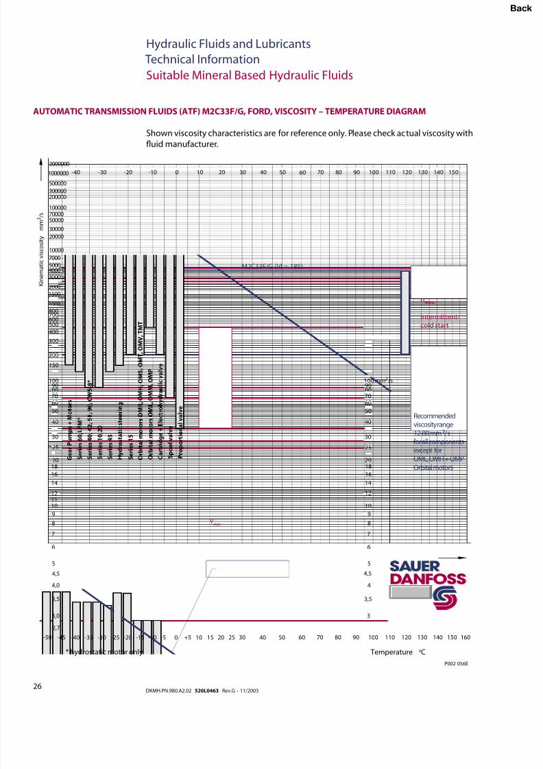
AUTOMATIC TRANSMISSION FLUIDS (ATF) M2C33F/G, FORD, VISCOSITY – TEMPERATURE DIAGRAM
Suitable Mineral Based Hydraulic Fluids
Shown viscosity characteristics are for reference only. Please check actual viscosity withuid manufacturer.
3,0
3,5
4,0
4,5
5
6
7
8
9
101112
14
16
1820
25
30
40
5060
708090
100
2,7
150
200
300
4005006007008001000
15002000
3000400050007000
10000
20000
30000
5000070000100000
200000300000
500000
2000000
-50 -45 -40 -35 -30 -25 -20 -15 -10 -5 0 +5 10 15 20 25 30 40 50 60 70 80 90 100 110 120 130 140 150 160
3
3,5
4
5
6
7
8
9
10
12
14
16
1820
25
30
40
5060
708090100
4,5
mm /s2
-40 -30 -20 -10 0 10 20 30 40 50 60 70 80 90 100 110 120 130 140 1501000000
K i n e m a t i c v i s c o s i t y
m m 2 / s
Recommendedviscosity range12-80 mm2 /sfor all componentsexcept forOML, OMH + OMPOrbital motors
nmax
intermittent-cold start
Temperature oC* hydrostatic motor only
P002 056E
S e r i e s 1 0 , 2
0
S e r i e s 4 5
S e r i e s 6 0 , L
P M *
S e r i e s 1 5
G e a r P u m p s + M o t o r
s
H y d r o s t a t i c s t e e r i n g
S e r i e s 4 0 ,
4 2 ,
5 1 ,
9 0 ,
C W 5 - 8 *
O r b i t a l m o t o r s O M R ,
O M H ,
O M S ,
O M T ,
O M V ,
T M T
O r b i t a l m o t o r s O M L ,
O M M ,
O M P
C a r t r i d g e + E l e c t r o h y d r a u l i c v a l v e
νmin
P r o p o r t i o n a l v a l v e
S p o o l v a l v e
M2C33F/G (VI = 185)
Bac
8/8/2019 Hydraulic Fluids and Lubricants TI Rev-G 11-2003
http://slidepdf.com/reader/full/hydraulic-fluids-and-lubricants-ti-rev-g-11-2003 27/48
27DKMH.PN.980.A2.02 520L0463 Rev.G – 11/2003
Hydraulic Fluids and Lubricants
Technical Information
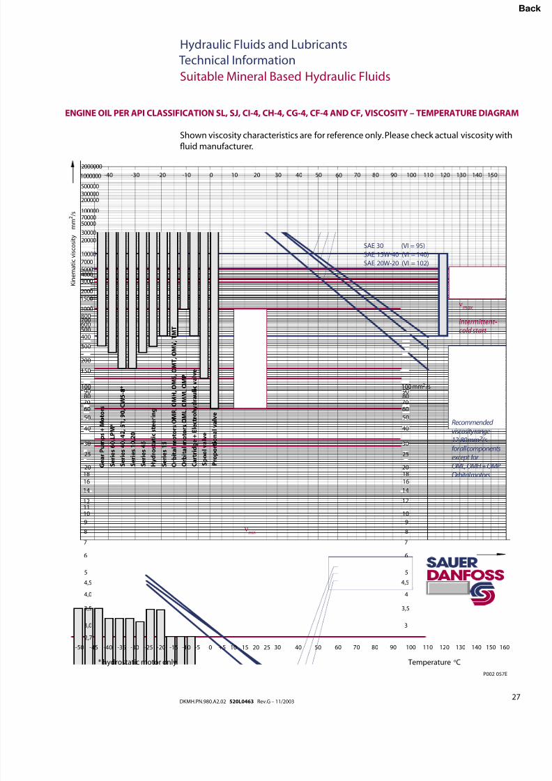
ENGINE OIL PER API CLASSIFICATION SL, SJ, CI-4, CH-4, CG-4, CF-4 AND CF, VISCOSITY – TEMPERATURE DIAGRAM
Suitable Mineral Based Hydraulic Fluids
Shown viscosity characteristics are for reference only. Please check actual viscosity withuid manufacturer.
3,0
3,5
4,0
4,5
5
6
7
8
9
101112
14
16
1820
25
30
40
5060
708090
100
2,7
150
200
300
4005006007008001000
15002000
3000400050007000
10000
20000
30000
5000070000100000
200000300000
500000
2000000
-50 -45 -40 -35 -30 -25 -20 -15 -10 -5 0 +5 10 15 20 25 30 40 50 60 70 80 90 100 110 120 130 140 150 160
3
3,5
4
5
6
7
8
9
10
12
14
16
1820
25
30
40
5060
708090100
4,5
mm /s2
-40 -30 -20 -10 0 10 20 30 40 50 60 70 80 90 100 110 120 130 140 1501000000
K i n e m
a t i c v i s c o s i t y
m m 2 / s
Recommended viscosity range12-80 mm2 /sfor all componentsexcept for OML, OMH + OMP Orbital motors
νmax
intermittent-cold start
Temperature oC* hydrostatic motor only
P002 057E
S e r i e s 1 0 , 2
0
S e r i e s 4 5
S e r i e s 6 0 , L
P M *
S e r i e s 1 5
G e a r P u m p s + M o t o r
s
H y d r o s t a t i c s t e e r i n g
S e r i e s 4 0 ,
4 2 ,
5 1 ,
9 0 ,
C W 5 - 8 *
O r b i t a l m o t o r s O M R ,
O M H ,
O M S ,
O M T ,
O M V ,
T M T
O r b i t a l m o t o r s O M L ,
O M M ,
O M P
C a r t r i d g e + E l e c t r o h y d r a u l i c v a l v e
νmin
P r o p o r t i o n a l v a l v e
S p o o l v a l v e
SAE 30 (VI = 95)
SAE 15W-40 (VI = 140)
SAE 20W-20 (VI = 102)
Bac
8/8/2019 Hydraulic Fluids and Lubricants TI Rev-G 11-2003
http://slidepdf.com/reader/full/hydraulic-fluids-and-lubricants-ti-rev-g-11-2003 28/48
28DKMH.PN.980.A2.02 520L0463 Rev.G – 11/2003
Hydraulic Fluids and Lubricants
Technical Information
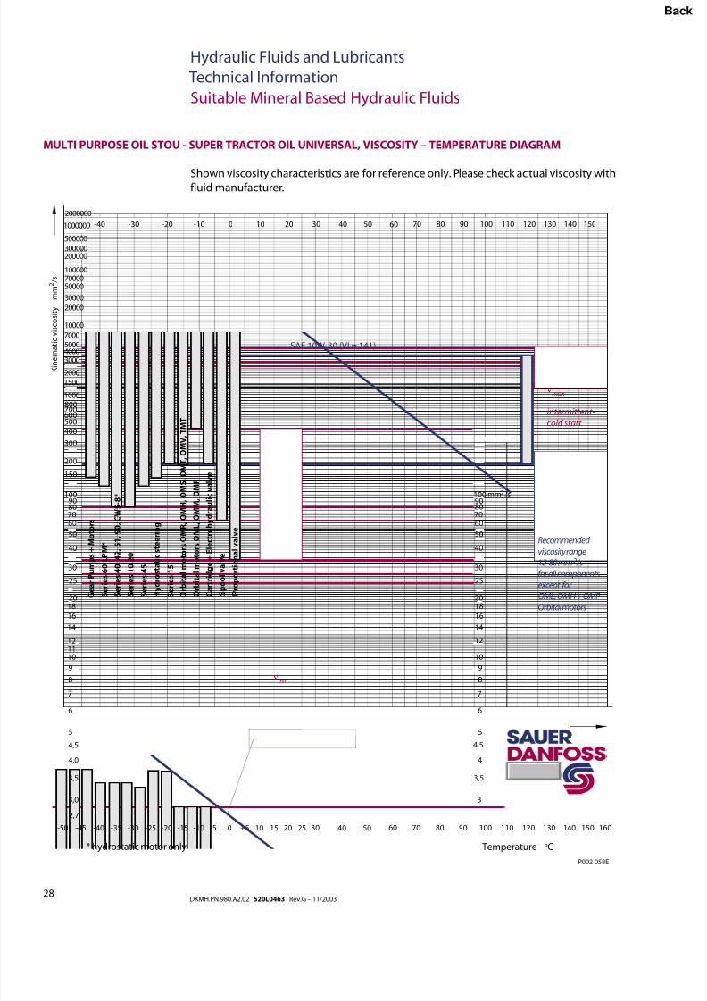
Suitable Mineral Based Hydraulic Fluids
Shown viscosity characteristics are for reference only. Please check actual viscosity withuid manufacturer.
MULTI PURPOSE OIL STOU - SUPER TRACTOR OIL UNIVERSAL, VISCOSITY – TEMPERATURE DIAGRAM
3,0
3,5
4,0
4,5
5
6
7
8
9
101112
14
16
1820
25
30
40
5060
708090
100
2,7
150
200
300
4005006007008001000
15002000
3000400050007000
10000
20000
30000
5000070000100000
200000300000
500000
2000000
-50 -45 -40 -35 -30 -25 -20 -15 -10 -5 0 +5 10 15 20 25 30 40 50 60 70 80 90 100 110 120 130 140 150 160
3
3,5
4
5
6
7
8
9
10
12
14
16
1820
25
30
40
5060
708090100
4,5
mm /s2
-40 -30 -20 -10 0 10 20 30 40 50 60 70 80 90 100 110 120 130 140 1501000000
K i n e m a t i c v i s c o s i t y
m m 2 / s
Recommended
viscosity range12-80 mm2 /s
for all components
except for
OML, OMH + OMP Orbital motors
νmax
intermittent-
cold start
Temperature oC* hydrostatic motor only
P002 058E
S e r i e s 1 0 , 2
0
S e r i e s 4 5
S e r i e s 6 0 , L
P M *
S e r i e s 1 5
G e a r P u m p s + M o t o r s
H y d r o s t a t i c s t e e r i n g
S e r i e s 4 0 ,
4 2 ,
5 1 ,
9 0 ,
C W 5 - 8 *
O r b i t a l m o t o r s O M R
, O M H ,
O M S ,
O M T ,
O M V ,
T M T
O r b i t a l m o t o r s O M L ,
O M M ,
O M P
C a r t r i d g e + E l e c t r o h
y d r a u l i c v a l v e
νmin
P r o p o r t i o n a l v a l v e
S p o o l v a l v e
SAE 10W-30 (VI = 141)
Bac
8/8/2019 Hydraulic Fluids and Lubricants TI Rev-G 11-2003
http://slidepdf.com/reader/full/hydraulic-fluids-and-lubricants-ti-rev-g-11-2003 29/48
29DKMH.PN.980.A2.02 520L0463 Rev.G – 11/2003
Hydraulic Fluids and Lubricants
Technical Information
Fire Resistant Hydraulic Fluids
FIRE RESISTANT
HYDRAULIC FLUIDS
ACCORDING TODIN 24 317, DIN 24320,
VDMA 24 317, AND
ISO 12 922
HFA uids – oil-in-water emulsions according to DIN 24 320 and ISO 12 922.
There can be bacterial control problems and corrosion problems. Fluid pH stability can
be a problem and can cause wear and chemical reaction with aluminium. Also, there maybe a solvent action on some paints.
A positive head reservoir is required to maintain a positive inlet pressure when
operating, and to keep air out of internal passageways when shut down.
HFA uids are divided into two groups:
• HFAE uids are Oil-in-Water emulsions with low emulsion oil content according
to DIN 24 320 and ISO 12 922. Normally these uids contain 1 to 5 % emulsion oil
related to the volume.
• HFAS uids are solutions with typically not more than 10 % uid concentrate in
water according to ISO 12 922.
HFB uids – water-in-oil emulsions according to VDMA 24 317 and ISO 12 922.
These uids can break down with repeated freezing and thawing. Also, heating above
60 °C [140 °F] can cause emulsion breakdown. High specic gravity requires an elevated
reservoir and increased inlet line size. Monitoring of uid water content is necessary. Fre-
quent additions may be necessary in order to overcome evaporation losses. These uids
also show poor vapor phase corrosion inhibition.
HFC uids – watery polymer solutions or water glycols according to VDMA 24 317
and ISO 12 922.
They attack zinc and cadmium, and produces solvent action on some paints. For more
information contact the uid manufacturer. Wear of aluminum in transmission partssometimes occurs in the presence of these uids. Viton seals are not recommended. High
specic gravity requires an elevated reservoir and increased inlet line size. Water content
and pH-number may be a problem.
Bac
8/8/2019 Hydraulic Fluids and Lubricants TI Rev-G 11-2003
http://slidepdf.com/reader/full/hydraulic-fluids-and-lubricants-ti-rev-g-11-2003 30/48
30DKMH.PN.980.A2.02 520L0463 Rev.G – 11/2003
Hydraulic Fluids and Lubricants
Technical Information
Fire Resistant Hydraulic Fluids
FIRE RESISTANT
HYDRAULIC FLUIDS
ACCORDING TODIN 24 317, DIN 24 320,
VDMA 24 317, AND
ISO 12 922
(continued)
HFD uids – water free, synthetic uids according to VDMA 24 317 and ISO 12 922.
Viton seals are required. Consult the uid manufacturer to obtain a recommendation
of the particular uid used. These uids attack some plastics, zinc and cadmium. Highspecic gravity requires an elevated reservoir and increased inlet line size.
Some of these uids have caused high wear of aluminum parts in transmissions.
HFD uids are divided into four groups: HFDR, HFDS, HFDT,and HFDU.
• HFDR: Fluid based on Phosphorus acid Ester according to DIN 24 317 and
ISO 12 922. Used primarily in Great Britain in the mining industry.
• HFDS: Fluid based on Chlorinated Hydrocarbons according to DIN 24 317.
Used primarily in hydrodynamic clutches.
• HFDT: Fluid based on mixtures of Phosphorus acid Ester and Chlorinated Hydrocar-
bons according to DIN 24 317. Used primarily in hydrostatic transmissions.
• HFDU: Other synthetic hydraulic uids without water according to DIN 24 317 and
ISO 12 922. Used primarily in aviation hydrostatic.
Fluid conversion
Consult VDMA 24 314, ISO 7745 and the uid manufacturer guidelines when converting
to another hydraulic uid.
Use caution when converting an application to a different uid. Thoroughly test the new
uid in the application before committing to the change.
Bac
8/8/2019 Hydraulic Fluids and Lubricants TI Rev-G 11-2003
http://slidepdf.com/reader/full/hydraulic-fluids-and-lubricants-ti-rev-g-11-2003 31/48
31DKMH.PN.980.A2.02 520L0463 Rev.G – 11/2003
Hydraulic Fluids and Lubricants
Technical Information
Fire Resistant Hydraulic Fluids
REQUIREMENTS FOR FIRE
RESISTANT HYDRAULIC
FLUIDS
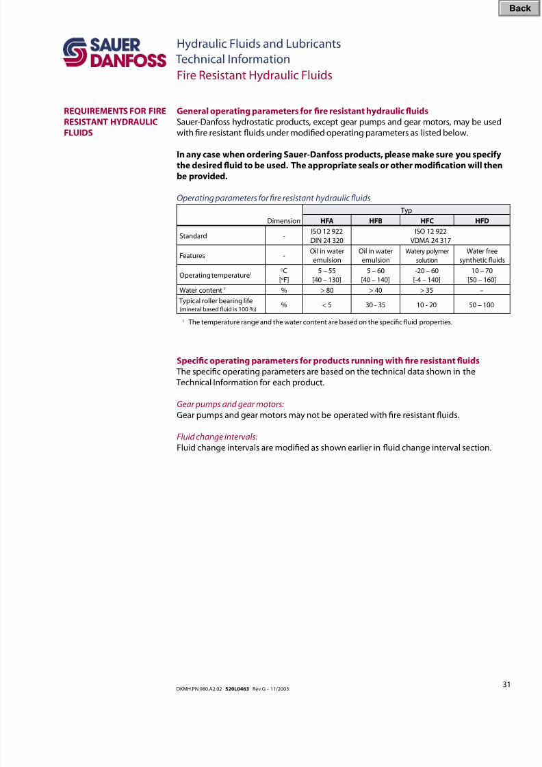
General operating parameters for re resistant hydraulic uids
Sauer-Danfoss hydrostatic products, except gear pumps and gear motors, may be used
with re resistant uids under modied operating parameters as listed below.
In any case when ordering Sauer-Danfoss products, please make sure you specify
the desired uid to be used. The appropriate seals or other modication will then
be provided.
Operating parameters for re resistant hydraulic uids
Dimension
Typ
HFA HFB HFC HFD
Standard -ISO 12 922
DIN 24 320
ISO 12 922
VDMA 24 317
Features -Oil in water
emulsion
Oil in water
emulsion
Watery polymer
solution
Water free
synthetic uids
Operating temperature1oC
[oF]5 – 55
[40 – 130]5 – 60
[40 – 140]-20 – 60
[-4 – 140]10 – 70
[50 – 160]
Water content 1 % > 80 > 40 > 35 –
Typical roller bearing life(mineral based uid is 100 %)
% < 5 30 - 35 10 - 20 50 – 100
1 The temperature range and the water content are based on the specic uid properties.
Specic operating parameters for products running with re resistant uids
The specic operating parameters are based on the technical data shown in the
Technical Information for each product.
Gear pumps and gear motors:Gear pumps and gear motors may not be operated with re resistant uids.
Fluid change intervals:
Fluid change intervals are modied as shown earlier in uid change interval section.
Bac
8/8/2019 Hydraulic Fluids and Lubricants TI Rev-G 11-2003
http://slidepdf.com/reader/full/hydraulic-fluids-and-lubricants-ti-rev-g-11-2003 32/48
32DKMH.PN.980.A2.02 520L0463 Rev.G – 11/2003
Hydraulic Fluids and Lubricants
Technical Information
Fire Resistant Hydraulic Fluids
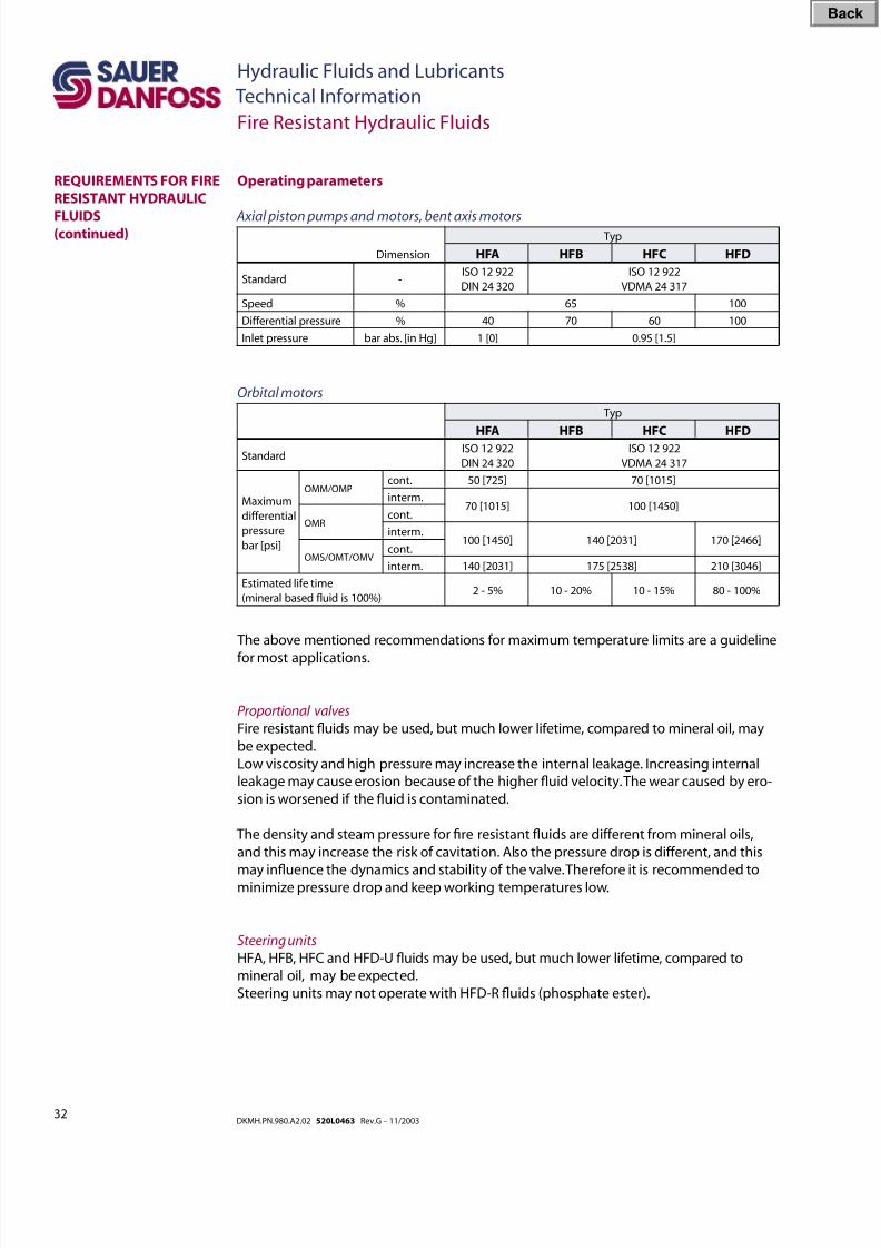
The above mentioned recommendations for maximum temperature limits are a guideline
for most applications.
Proportional valves
Fire resistant uids may be used, but much lower lifetime, compared to mineral oil, may
be expected.
Low viscosity and high pressure may increase the internal leakage. Increasing internal
leakage may cause erosion because of the higher uid velocity. The wear caused by ero-
sion is worsened if the uid is contaminated.
The density and steam pressure for re resistant uids are different from mineral oils,
and this may increase the risk of cavitation. Also the pressure drop is different, and this
may inuence the dynamics and stability of the valve. Therefore it is recommended tominimize pressure drop and keep working temperatures low.
Steering units
HFA, HFB, HFC and HFD-U uids may be used, but much lower lifetime, compared to
mineral oil, may be expected.
Steering units may not operate with HFD-R uids (phosphate ester).
Operating parameters
Axial piston pumps and motors, bent axis motors
Dimension
Typ
HFA HFB HFC HFD
Standard -ISO 12 922
DIN 24 320
ISO 12 922
VDMA 24 317
Speed % 65 100
Differential pressure % 40 70 60 100
Inlet pressure bar abs. [in Hg] 1 [0] 0.95 [1.5]
Orbital motors
Typ
HFA HFB HFC HFDStandard
ISO 12 922
DIN 24 320
ISO 12 922
VDMA 24 317
Maximum
differential
pressure
bar [psi]
OMM/OMPcont. 50 [725] 70 [1015]
interm.70 [1015] 100 [1450]
OMRcont.
interm.100 [1450] 140 [2031] 170 [2466]
OMS/OMT/OMVcont.
interm. 140 [2031] 175 [2538] 210 [3046]
Estimated life time
(mineral based uid is 100%)2 - 5% 10 - 20% 10 - 15% 80 - 100%
REQUIREMENTS FOR FIRE
RESISTANT HYDRAULIC
FLUIDS(continued)
Bac
8/8/2019 Hydraulic Fluids and Lubricants TI Rev-G 11-2003
http://slidepdf.com/reader/full/hydraulic-fluids-and-lubricants-ti-rev-g-11-2003 33/48
33DKMH.PN.980.A2.02 520L0463 Rev.G – 11/2003
Hydraulic Fluids and Lubricants
Technical Information
Biodegradable Hydraulic Fluids
BIODEGRADABLE
HYDRAULIC FLUIDS
ACCORDING TOVDMA 24 568 AND
ISO/CD 15 380
The growing environmental awareness has increased the research and development for
biodegradable hydraulic uids. Although these uids have improved over the last years
these are not yet ready to replace mineral based hydraulic uids. Still several perfor-mance issues need to be improved.
The minimum technical requirements for biodegradable hydraulic uids are specied in
the German standard VDMA 24 568 – Rapidly Biologically Degradable Hydraulic Fluids
Minimum Technical Requirements
The VDMA 24 568 is a preliminary guideline. Several technical data have to be evaluated
and specied for the use in hydrostatic transmissions by the standardization group.
Therefore todays hydraulic uids following VDMA 24 568 do not operate satisfactory
under all circumstances.
A new ISO standard for biodegradable hydraulic uids is under development:
ISO/CD 15 380, Lubricants, industrial oils and related products (class L)
– Family H (Hydraulic systems)
– Specications for categories HETG, HEPG, HEES, and HEPR
Since long term experience is not yet available on the application of biodegradable
hydraulic uids, Sauer-Danfoss does not guarantee awless operation of these uids for
every application.
For high performance installations we recommend thorough eld testing of the uid
in questions.
In addition, the adherence to minimum requirements does not mean that the hydraulic
uid may be used without restrictions. Before using a biodegradable hydraulic uidplease see attached list of Sauer-Danfoss experience with biodegradable hydraulic uids
or contact Sauer-Danfoss.
Before changing a machine over to a new oil it is imperative to consult with the individual
manufacturer of each machine.
Warning
To avoid damage caused by the hydraulic uid we recommend to take uid samples
every 150 – 200 operating hours. The uid manufacturer should check the further
uid usability.
All biodegradable hydraulic uids are subject to special disposal regulations similarto mineral based hydraulic uids. The legal national and international ordinances and
regulations will apply. Particularly the instructions of the uid manufacturer must be
followed.
For information: Many uid manufacturers voluntarily offer to take back the used uids.
Bac
8/8/2019 Hydraulic Fluids and Lubricants TI Rev-G 11-2003
http://slidepdf.com/reader/full/hydraulic-fluids-and-lubricants-ti-rev-g-11-2003 34/48
34DKMH.PN.980.A2.02 520L0463 Rev.G – 11/2003
Hydraulic Fluids and Lubricants
Technical Information
HETG - Triglyceride hydraulic uids
Fluid characteristics• very good viscosity-temperature behavior
• high biological degradability
• water hazard class WGK 0
• good corrosion protection
• good compatibility with seals/gaskets
• density approximately 0.92 g/ml
• pour point approximately -10 °C to -25 °C [-50 to -77 °F]. (The uid may become
solid after extended storage at low temperatures. For further questions please con-
tact the uid manufacturer.)
• the minimum requirements of VDMA 24 568 are generally met.
• the minimum requirements of ISO/CD 15 380 are generally met
Operating data
Under consideration of the HETG uid properties the temperature range, however,
is limited to -15 °C to 70 °C [-59 °F to 158 °F]
In order to avoid accelerated aging of the uid , tank temperatures above 60 °C [140 °F]
should be avoided.
Warning
All hydraulic components are tested with mineral oil! All housings must be drained
completely before installation!
Fluid change interval:Fluid change intervals are modied as shown earlier in uid change interval section.
Note: Before using a biodegradable hydraulic uid please ask for list of Sauer-Danfoss
experience with biodegradable hydraulic uids.
Hints for transition
VDMA 24 569–Rapidly Biologically Degradable Hydraulic Fluids, ISO/CD 15 380, and the
appropriate guidelines of each individual hydraulic uid manufacturer are applicable. The
remaining max residual volume as specied in VDMA 24 569 and ISO/CD 15 380 must
not be exceeded.
Requirements for biodegradable hydraulic uids HETG
The requirements concerning water content, Viscosity–Temperature limits, cleanliness
level described in the section Requirements of hydraulic uids must be met in addition
to above mentioned requirements, especially the needed temperature limitations to
prevent rapid uid ageing.
BIODEGRADABLE
HYDRAULIC FLUIDS
ACCORDING TOVDMA 24 568 AND
ISO/CD 15 380
(continued)
Biodegradable Hydraulic Fluids
Bac
8/8/2019 Hydraulic Fluids and Lubricants TI Rev-G 11-2003
http://slidepdf.com/reader/full/hydraulic-fluids-and-lubricants-ti-rev-g-11-2003 35/48
35DKMH.PN.980.A2.02 520L0463 Rev.G – 11/2003
Hydraulic Fluids and Lubricants
Technical Information
HEPG – Poly glycol hydraulic uids
Fluid characteristics• very good viscosity-temperature behavior
• biologically degradable
• water hazard class WGK 0
• good corrosion protection
• partially unacceptable compatibility with seals/gaskets
• density > 1.0 g/ml
• pour point approximately -10 °C to -25 °C [-50 to -77 °F].
• the minimum requirements of VDMA 24 568 are generally met
• the minimum requirements of ISO/CD 15 380 are generally met
Operating data
Due to the higher density compared to mineral oil the permissible suction pressure must
be strictly adhered to.
Warning
All hydraulic components are tested with mineral oil! All housings must be drained
completely before installation!
Note: Before using a biodegradable hydraulic uid please ask for list of Sauer-Danfoss
experience with biodegradable hydraulic uids.
Hints for transition
Based on a few particular characteristics of poly glycol based uids, as for example,
• partially unacceptable paint incompatibility• low seal/gasket compatibility
• no mixability with mineral oil
the exchange of uids in existing installation may be very expensive.
VDMA 24 569 – Rapidly Biologically Degradable Hydraulic Fluids, ISO/CD 15 380, and
the appropriate guidelines of each individual hydraulic uid manufacturer are applicable.
The remaining max residual volume as specied in VDMA 24 569 and ISO/CD 15 380 must
not be exceeded.
Requirements for biodegradable hydraulic uids HEPG
The requirements concerning water content, Viscosity–Temperature limits, cleanlinesslevel described in the section Requirements of hydraulic uids must be met in addition to
above mentioned requirements.
BIODEGRADABLE
HYDRAULIC FLUIDS
ACCORDING TOVDMA 24 568 AND
ISO/CD 15 380
(continued)
Biodegradable Hydraulic Fluids
Bac
8/8/2019 Hydraulic Fluids and Lubricants TI Rev-G 11-2003
http://slidepdf.com/reader/full/hydraulic-fluids-and-lubricants-ti-rev-g-11-2003 36/48
36DKMH.PN.980.A2.02 520L0463 Rev.G – 11/2003
Hydraulic Fluids and Lubricants
Technical Information
HEES – Synthetic ester based hydraulic uids
Fluid characteristics:• very good viscosity-temperature behavior
• biologically well degradable
• water hazard class WGK 0
• good corrosion protection
• good compatibility with seals/gaskets
• good lubricating characteristics
• good aging resistance
• density approximately 0.92 g/ml
• pour point approximately -10 °C to -25 °C [-50 to -77 °F].
• the minimum requirements of VDMA 24 568 are generally met
• the minimum requirements of ISO/CD 15 380 are generally met
Operating data
Due to the higher density compared to mineral oil the permissible suction pressure must
be strictly adhered to.
Warning
All hydraulic components are tested with mineral oil! All housings must be drained
completely before installation!
Note: Before using a biodegradable hydraulic uid please ask for list of Sauer-Danfoss
experience with biodegradable hydraulic uids.
Hints for transitionVDMA 24 569 – Rapidly Biologically Degradable Hydraulic Fluids, ISO/CD 15 380, and
the appropriate guidelines of each individual hydraulic uid manufacturer are applicable.
The remaining max residual volume as specied in VDMA 24 569 and ISO/CD 15 380 must
not be exceeded.
Requirements for biodegradable hydraulic uids HEES
The requirements concerning water content, Viscosity–Temperature limits, cleanliness
level described in the section Requirements of hydraulic uids must be met in addition to
above mentioned requirements.
BIODEGRADABLE
HYDRAULIC FLUIDS
ACCORDING TOVDMA 24 568 AND
ISO/CD 15 380
(continued)
Biodegradable Hydraulic Fluids
Bac
8/8/2019 Hydraulic Fluids and Lubricants TI Rev-G 11-2003
http://slidepdf.com/reader/full/hydraulic-fluids-and-lubricants-ti-rev-g-11-2003 37/48
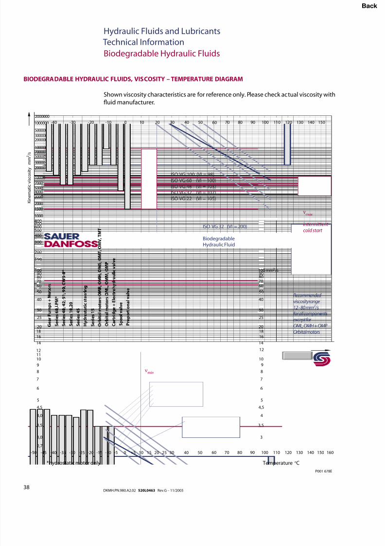
8/8/2019 Hydraulic Fluids and Lubricants TI Rev-G 11-2003
http://slidepdf.com/reader/full/hydraulic-fluids-and-lubricants-ti-rev-g-11-2003 38/48
38DKMH.PN.980.A2.02 520L0463 Rev.G – 11/2003
Hydraulic Fluids and Lubricants
Technical Information
BIODEGRADABLE HYDRAULIC FLUIDS, VISCOSITY – TEMPERATURE DIAGRAM
Biodegradable Hydraulic Fluids
Shown viscosity characteristics are for reference only. Please check actual viscosity withuid manufacturer.
3,0
3,5
4,0
4,5
5
6
7
8
9
101112
14
16
1820
25
30
40
5060
708090
100
2,7
150
200
300
4005006007008001000
15002000
3000400050007000
10000
20000
30000
5000070000100000
200000300000
500000
2000000
-50 -45 -40 -35 -30 -25 -20 -15 -10 -5 0 +5 10 15 20 25 30 40 50 60 70 80 90 100 110 120 130 140 150 160
3
3,5
4
5
6
7
8
9
10
12
14
16
1820
25
30
40
5060
708090100
4,5
mm /s2
-40 -30 -20 -10 0 10 20 30 40 50 60 70 80 90 100 110 120 130 140 1501000000
K i n e m a t i c v i s c o s i t y
m m 2 / s
Recommended viscosity range12 - 80 mm2 /sfor all componentsexcept for OML, OMH + OMP Orbital motors
νmax
intermittent-cold start
Temperature oC*hydrostatic motor only
P001 678E
ISO VG 100 (VI = 98)ISO VG 68 (VI = 100)ISO VG 46 (VI = 103)
ISO VG 32 (VI = 107)ISO VG 22 (VI = 105)
S e r i e s 1 0 , 2
0
S e r i e s 4 5
S e r i e s 6 0 , L
P M *
S e r i e s 1 5
G e a r P u m p s + M o t o r
s
H y d r o s t a t i c s t e e r i n g
S e r i e s 4 0 ,
4 2 ,
5 1 ,
9 0 ,
C W 5 - 8 *
O r b i t a l m o t o r s O M R ,
O M H ,
O M S ,
O M T ,
O M V ,
T M T
O r b i t a l m o t o r s O M L ,
O M M ,
O M P
C a r t r i d g e + E l e c t r o h y d r a u l i c v a l v e
P r o p o r t i o n a l v a l v e
S p o o l v a l v e
νmin
ISO VG 32 (VI = 200) BiodegradableHydraulic Fluid
Bac
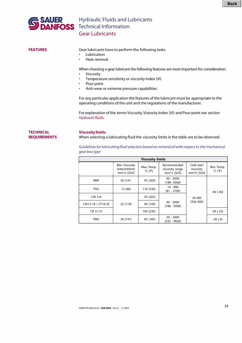
8/8/2019 Hydraulic Fluids and Lubricants TI Rev-G 11-2003
http://slidepdf.com/reader/full/hydraulic-fluids-and-lubricants-ti-rev-g-11-2003 39/48
39DKMH.PN.980.A2.02 520L0463 Rev.G – 11/2003
Hydraulic Fluids and Lubricants
Technical Information
Gear Lubricants
FEATURES Gear lubricants have to perform the following tasks:
• Lubrication
• Heat removal
When choosing a gear lubricant the following features are most important for consideration:
• Viscosity
• Temperature sensitivity or viscosity Index (VI)
• Pour point
• Anti-wear or extreme pressure capabilities
For any particular application the features of the lubricant must be appropriate to the
operating conditions of the unit and the regulations of the manufacturer.
For explanation of the terms Viscosity, Viscosity Index (VI) and Pour point see section
Hydraulic uids.
Viscosity limits
When selecting a lubricating uid the viscosity limits in the table are to be observed.
Guidelines for lubricating uid selection based on mineral oil with respect to the mechanical
gear box type
TECHNICAL
REQUIREMENTS
stimilytisocsiV
tinU ytisocsiV.niM
)tnettimretni(
mm 2 ]SUS[s /
.pme T.xaMo [C o ]F
dednemmoceR
egnarytisocsiv
mm 2 ]SUS[s /
tratsdloC
ytisocsiv
mm 2 ]SUS[s /
.pme T.niMo [C o ]F
seireS
FMR ]141[03 ]302[590002-04
]0629-681[
00002
]000629[
]04-[04-GVP ]66[21 ]032[011
008-61
]0073-18[
8-5WC
]911[52
]302[59
0002-04
]0629-681[53-81 TC /81-21WC ]491[09
15-13RC ]032[001 ]22-[03-
GM T ]141[03 ]581[580002-05
]0269-232[]4-[02-
Bac
8/8/2019 Hydraulic Fluids and Lubricants TI Rev-G 11-2003
http://slidepdf.com/reader/full/hydraulic-fluids-and-lubricants-ti-rev-g-11-2003 40/48
40DKMH.PN.980.A2.02 520L0463 Rev.G – 11/2003
Hydraulic Fluids and Lubricants
Technical Information
Gear Lubricants
SUITABLE GEAR
LUBRICANTS
General
The lubricants are to be chosen together with the gear manufacturer for each application.
Sauer-Danfoss gearboxes may be operated with a variety of lubricants.
The following are suitable:
• Lubricant DIN 51 517, part 3 - CLP
• Lubricant API-Classication GL4 or MIL-L-2105
• Lubricant API-Classication GL5 or MIL-L-2005
The Sauer-Danfoss warranty claim policies do not apply for uid related damage.
The rated data which we publish in our Technical Information and Service Manuals are
based on the use of premium lubricants containing oxidation, rust, and foam inhibitors.
It is not permissible to mix lubricants. The different additive package may cause negative
interactions.
If lubricants mixing can not be avoided, uid manufacturers approval is required.
The Sauer-Danfoss warranty claim policies do not apply for uid related damage which
result from mixing.
Example for selecting the kinematic viscosity
See also the Nomograph on the next page.
Example: Transit Mixer Drive (agitate mode)
a) assumed: 1 Power 15 kW [20 hp] 2 Output speed 4 min-1 (rpm)
3 Gear ratio i = 99
- Temperature 55 °C [131 °F]
b) Nomograph:
5 required viscosity at operating temperature 180 mm2 /s
[833.3 SUS]
c) Viscosity–temperature diagram
- required lubricant CLP 460
Warning
Determination of the viscosity is only a reference value.
If the viscosity is between two different ISO Viscosity grades, use the closests grade.
For a further information and selection of a lubricant, please contact your local
Sauer-Danfoss representative.
For transit mixer boxes EP-Gear lubricants according to API-Classication GL-5 should
always be selected. Normally Gear lubricants with SAE-Viscosity grade 90 are suitable. At
higher temperatures we recommend Gear Lubricants with SAE-Viscosity grade 140.
GEAR LUBRICANT
APPLICATION
Bac
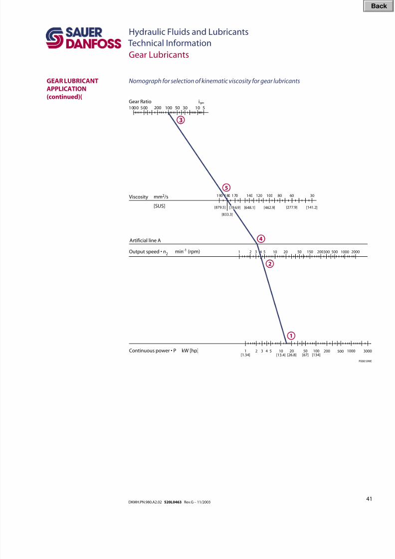
8/8/2019 Hydraulic Fluids and Lubricants TI Rev-G 11-2003
http://slidepdf.com/reader/full/hydraulic-fluids-and-lubricants-ti-rev-g-11-2003 41/48
41DKMH.PN.980.A2.02 520L0463 Rev.G – 11/2003
Hydraulic Fluids and Lubricants
Technical Information
Gear Lubricants
GEAR LUBRICANT
APPLICATION
(continued)(
Nomograph for selection of kinematic viscosity for gear lubricants
1000 500 200 100 50 30 10 5
Gear Ratio iges
Viscosity 190 180 170 140 120 100 80 60 30 mm2 /s
[SUS]
1 2 150
Artificial line A
3 4 5 10 20 50 200300 500 1000 2000Output speed • n2
1[1.34]
2 4 10[13.4]
20[26.8]
50[67]
100[134]
3 5 200 500 1000 3000Continuous power • P kW [hp]
1
2
5
3
min-1 (rpm)
P000 599E
4
[879.5]
[833.3]
[78 6.9] [648.1] [462.9] [277.9] [141.2]
Bac
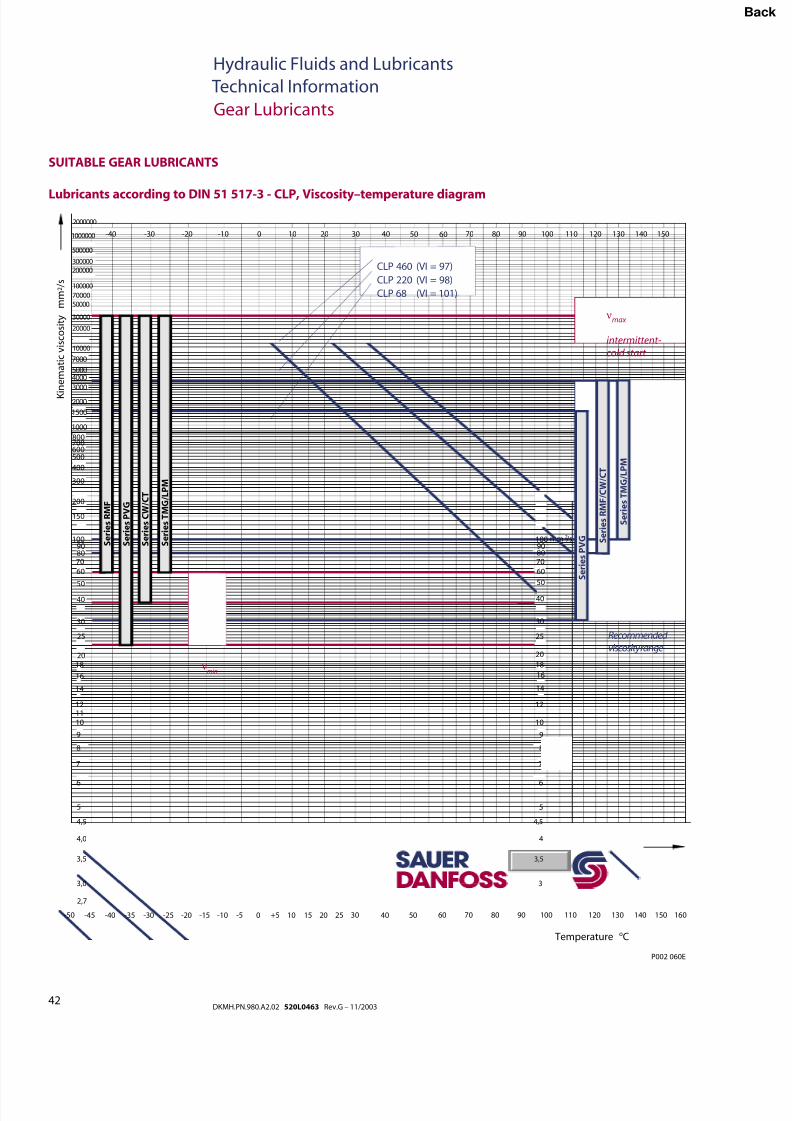
8/8/2019 Hydraulic Fluids and Lubricants TI Rev-G 11-2003
http://slidepdf.com/reader/full/hydraulic-fluids-and-lubricants-ti-rev-g-11-2003 42/48
42DKMH.PN.980.A2.02 520L0463 Rev.G – 11/2003
Hydraulic Fluids and Lubricants
Technical Information
Gear Lubricants
SUITABLE GEAR LUBRICANTS
Lubricants according to DIN 51 517-3 - CLP, Viscosity–temperature diagram
Temperature oC
K i n e m a t i c v i s c o s i t y
m m 2 / s
3,0
3,5
4,0
4,5
5
6
7
8
9
101112
14
16
1820
25
30
40
50
60
708090
100
2,7
150
200
300
400
500600700800
1000
1500
2000
3000
40005000
7000
10000
20000
30000
5000070000
100000
200000300000
500000
2000000
-50 -45 -40 -35 -30 -25 -20 -15 -10 -5 0 +5 10 15 20 25 30 40 50 60 70 80 90 100 110 120 130 140 150 160
3
3,5
4
5
6
7
8
9
10
12
14
16
18
20
25
30
40
50
60
708090100
4,5
mm /s2
-40 -30 -20 -10 0 10 20 30 40 50 60 70 80 90 100 110 120 130 140 1501000000
S e r i e s R M F
S e r i e s T M G / L P M
S e r i e s P V G
νmin
S e r i e s R M F / C W / C T
S e r i e s T M G / L P M
S e r i e s P V G
P002 060E
S e r i e s C W / C T
CLP 460 (VI = 97)
CLP 220 (VI = 98)
CLP 68 (VI = 101)
Recommended viscosity range
νmax
intermittent-cold start
Bac
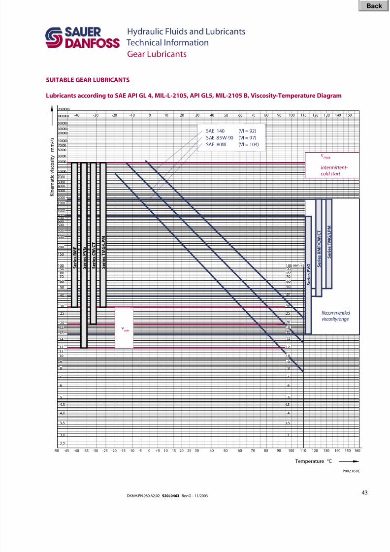
8/8/2019 Hydraulic Fluids and Lubricants TI Rev-G 11-2003
http://slidepdf.com/reader/full/hydraulic-fluids-and-lubricants-ti-rev-g-11-2003 43/48
43DKMH.PN.980.A2.02 520L0463 Rev.G – 11/2003
Hydraulic Fluids and Lubricants
Technical Information
Gear Lubricants
SUITABLE GEAR LUBRICANTS
Lubricants according to SAE API GL 4, MIL-L-2105, API GL5, MIL-2105 B, Viscosity-Temperature Diagram
Temperature oC
K i n e m a t i c v i s c o s i t y
m m 2 / s
3,0
3,5
4,0
4,5
5
6
7
8
9
101112
14
16
1820
25
30
40
50
60
708090
100
2,7
150
200
300
400
500600700800
1000
1500
2000
3000
40005000
7000
10000
20000
30000
5000070000
100000
200000300000
500000
2000000
-50 -45 -40 -35 -30 -25 -20 -15 -10 -5 0 +5 10 15 20 25 30 40 50 60 70 80 90 100 110 120 130 140 150 160
3
3,5
4
5
6
7
8
9
10
12
14
16
18
20
25
30
40
50
60
708090100
4,5
mm /s2
-40 -30 -20 -10 0 10 20 30 40 50 60 70 80 90 100 110 120 130 140 1501000000
S e r i e s R M F
S e r i e s T M G / L P M
S e r i e s P V G
νmin
S e r i e s R M F / C W / C T
S e r i e s T M G / L P M
S e r i e s P V G
SAE 140 (VI = 92)
SAE 85W-90 (VI = 97)
SAE 80W (VI = 104)
P002 059E
S e r i e s C W / C T
Recommended viscosity range
νmax
intermittent-cold start
Bac
8/8/2019 Hydraulic Fluids and Lubricants TI Rev-G 11-2003
http://slidepdf.com/reader/full/hydraulic-fluids-and-lubricants-ti-rev-g-11-2003 44/48
44DKMH.PN.980.A2.02 520L0463 Rev.G – 11/2003
Hydraulic Fluids and Lubricants
Technical Information
Gear Bearing Grease
FEATURES Gear bearing grease has to perform the following task – Lubrication.
Roller bearing grease does not ow out of the bearing housing. The free space of a roller bearing can be lled well due to the plastic, easily deformable
structure. The lled grease quantity lubricates for a long period of time, as the required
lubricant remains in the bearing.
Roller bearing greases serve to reduce friction wear and temperature and protect against
corrosion. Bearing grease seals against external inuences such as dust and humidity.
The high durability of a gear bearing grease avoids damage and machinery breakdown
and increase the life of the gears. High-grade bearing grease has a wide range of uses.
It distinguishes itself by constant temperatures, being waterproof and work endurance
consistency.
Furthermore, grease has a good oxidation stability and excellent corrosion protection.
Even at low temperatures the greases listed in the table are still easily transportable and
render an easy bearing start-up possible.
Dropping point (DIN ISO 2176)
The dropping point of a bearing grease is the temperature at which the rst drop of
grease brought to melting falls from a DIN-ISO 2176 standardized test unit.
The dropping point of grease must always be above the intended bearing temperature.
Miscibility of gear bearing grease
Mixing of different soapanication agents is to be avoided. To be checked by greasemanufacturer if desired.
Such mixtures are often the cause of damage due to “liquefaction” or “hardening” of the
grease mixture. When adjusting or even renewing the grease, remove the “old” grease
completely.
Storage of gear bearing grease
Store grease in a dry area, if possible indoor.
Buckets, large canisters or barrels are to be sealed with the lid immediately after use.
Bac
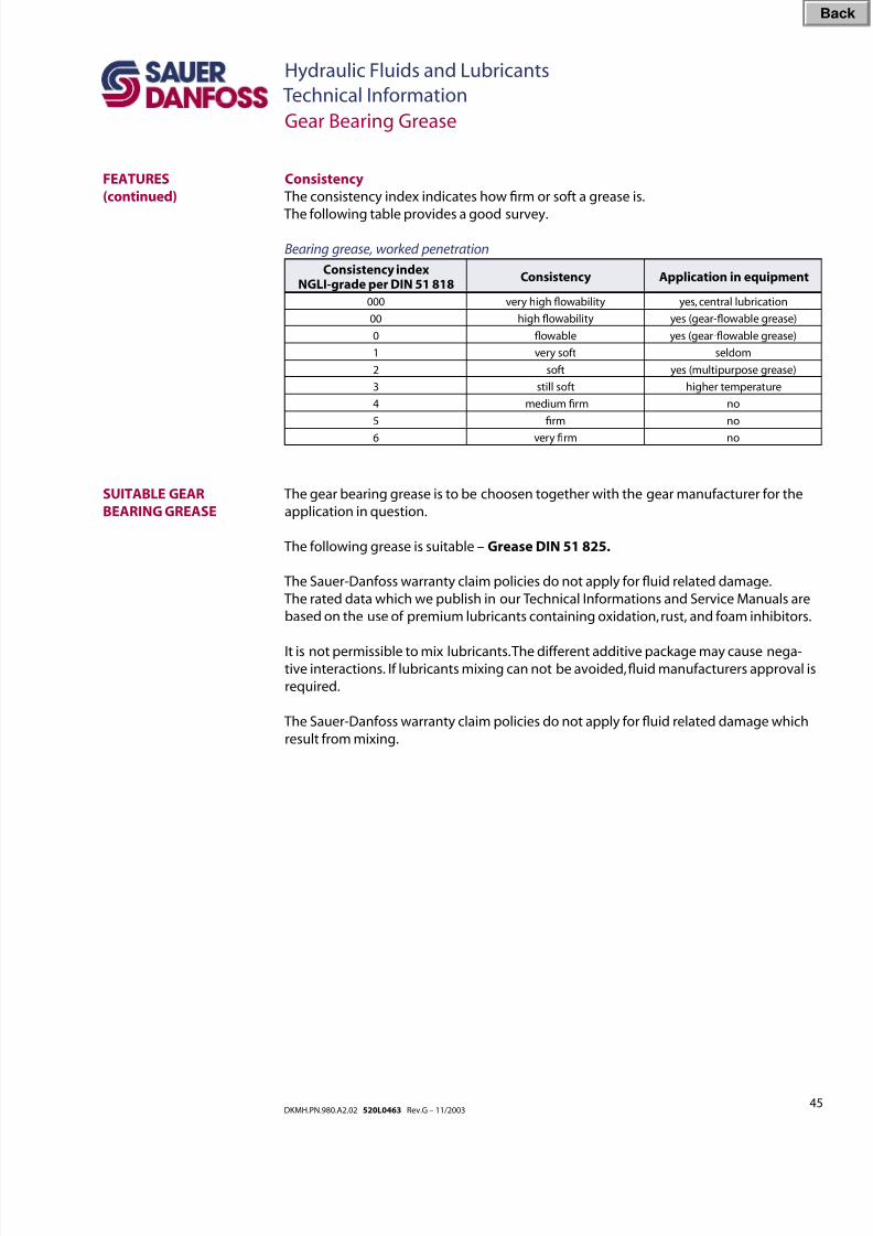
8/8/2019 Hydraulic Fluids and Lubricants TI Rev-G 11-2003
http://slidepdf.com/reader/full/hydraulic-fluids-and-lubricants-ti-rev-g-11-2003 45/48
45DKMH.PN.980.A2.02 520L0463 Rev.G – 11/2003
Hydraulic Fluids and Lubricants
Technical Information
Gear Bearing Grease
FEATURES
(continued)
Consistency
The consistency index indicates how rm or soft a grease is.
The following table provides a good survey.
Bearing grease, worked penetration
Consistency indexNGLI-grade per DIN 51 818
Consistency Application in equipment
000 very high owability yes, central lubrication
00 high owability yes (gear-owable grease)
0 owable yes (gear-owable grease)
1 very soft seldom
2 soft yes (multipurpose grease)
3 still soft higher temperature
4 medium rm no
5 rm no
6 very rm no
The gear bearing grease is to be choosen together with the gear manufacturer for the
application in question.
The following grease is suitable – Grease DIN 51 825.
The Sauer-Danfoss warranty claim policies do not apply for uid related damage.
The rated data which we publish in our Technical Informations and Service Manuals are
based on the use of premium lubricants containing oxidation, rust, and foam inhibitors.
It is not permissible to mix lubricants. The different additive package may cause nega-tive interactions. If lubricants mixing can not be avoided, uid manufacturers approval is
required.
The Sauer-Danfoss warranty claim policies do not apply for uid related damage which
result from mixing.
SUITABLE GEAR
BEARING GREASE
Bac
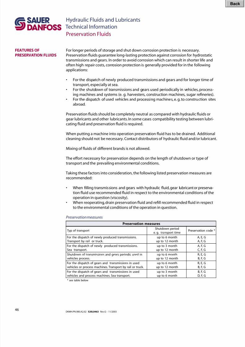
8/8/2019 Hydraulic Fluids and Lubricants TI Rev-G 11-2003
http://slidepdf.com/reader/full/hydraulic-fluids-and-lubricants-ti-rev-g-11-2003 46/48
46DKMH.PN.980.A2.02 520L0463 Rev.G – 11/2003
Hydraulic Fluids and Lubricants
Technical Information
Preservation Fluids
FEATURES OF
PRESERVATION FLUIDS
For longer periods of storage and shut down corrosion protection is necessary.
Preservation uids guarantee long-lasting protection against corrosion for hydrostatic
transmissions and gears. In order to avoid corrosion which can result in shorter life andoften high repair costs, corrosion protection is generally provided for in the following
applications:
• For the dispatch of newly produced transmissions and gears and for longer time of
transport, especially at sea.
• For the shutdown of transmissions and gears used periodically in vehicles, process-
ing machines and systems (e. g. harvesters, construction machines, sugar reneries).
• For the dispatch of used vehicles and processing machines, e. g. to construction sites
abroad.
Preservation uids should be completely neutral as compared with hydraulic uids or
gear lubricants and other lubricants. In some cases compatibility testing between lubri-
cating uid and preservation uid is required.
When putting a machine into operation preservation uid has to be drained. Additional
cleaning should not be necessary. Contact distributors of hydraulic uid and/or lubricant.
Mixing of uids of different brands is not allowed.
The effort necessary for preservation depends on the length of shutdown or type of
transport and the prevailing environmental conditions.
Taking these factors into consideration, the following listed preservation measures are
recommended:
• When lling transmissions and gears with hydraulic uid, gear lubricant or preserva-
tion uid use recommended uid in respect to the environmental conditions of the
operation in question (viscosity).
• When reoperating, drain preservation uid and rell recommended uid in respect
to the environmental conditions of the operation in question.
Preservation measures
serusaemnoitavreserP
tropsnartf opy TdoirepnwodtuhS
emittropsnart.g.e*edocnoitavreserP
.snoissimsnartdecudorpylwenf ohctapsidehtroF
.k curtroliarybtropsnar T
htnom6otpu
htnom21otpu
G,E,A
G,F,A
.snoissimsnartdecudorpylwenf ohctapsidehtroF
.tropsnartaeS
htnom3otpu
htnom21otpu
G,F,A
G,F,C
nidesucidoirepsraegdnasnoissimsnartf onwodtuhS
.ssecorpselcihev
htnom6otpu
htnom21otpu
G,E,B
G,F,B
desunisnoissimsnartdnasraegf ohctapsidehtroF
.k curtroliarybtropsnar T.senihcamssecorproselcihev
htnom6otpu
htnom21otpu
G,E,B
G,F,B
desunisnoissimsnartdnasraegf ohctapsidehtroF
.tropsnartaeS.senihcamssecorpdnaselcihev
htnom3otpu
htnom6otpu
G,F,B
G,F,D
wolebelbatees*
Bac
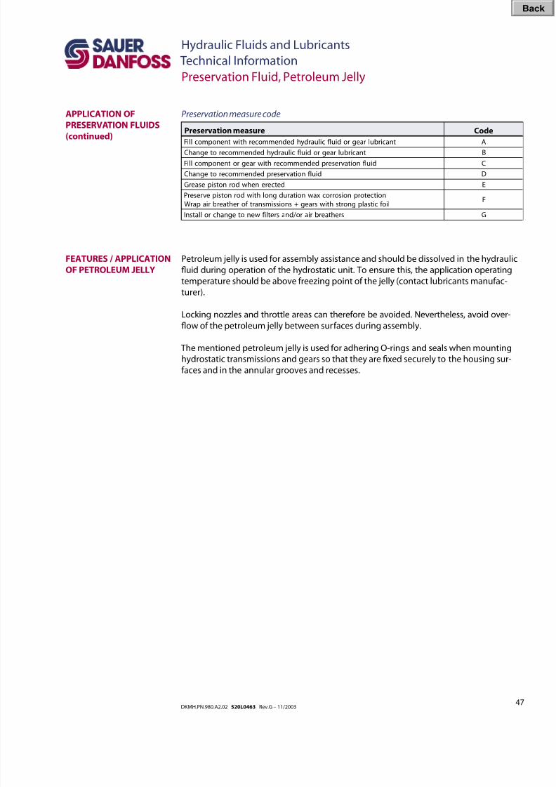
8/8/2019 Hydraulic Fluids and Lubricants TI Rev-G 11-2003
http://slidepdf.com/reader/full/hydraulic-fluids-and-lubricants-ti-rev-g-11-2003 47/48
47DKMH.PN.980.A2.02 520L0463 Rev.G – 11/2003
Hydraulic Fluids and Lubricants
Technical Information
Preservation Fluid, Petroleum Jelly
APPLICATION OF
PRESERVATION FLUIDS
(continued)
FEATURES / APPLICATION
OF PETROLEUM JELLY
Petroleum jelly is used for assembly assistance and should be dissolved in the hydraulic
uid during operation of the hydrostatic unit. To ensure this, the application operating
temperature should be above freezing point of the jelly (contact lubricants manufac-
turer).
Locking nozzles and throttle areas can therefore be avoided. Nevertheless, avoid over-
ow of the petroleum jelly between surfaces during assembly.
The mentioned petroleum jelly is used for adhering O-rings and seals when mounting
hydrostatic transmissions and gears so that they are xed securely to the housing sur-
faces and in the annular grooves and recesses.
tnacirbulraegrodiulf ciluardyhdednemmocerhtiwtnenopmoclliF A
tnacirbulraegrodiulf ciluardyhdednemmocerotegnahC B
diulf noitavreserpdednemmocerhtiwraegrotnenopmoclliF C
diulf noitavreserpdednemmocerotegnahC D
detcerenehwdornotsipesaerG E
noitcetorpnoisorrocxawnoitarudgnolhtiwdornotsipevreserP
liof citsalpgnortshtiwsraeg+snoissimsnartf orehtaerbriaparWF
srehtaerbriaro /dnasretlif wenotegnahcrollatsnI G
Preservation measure Code Preservation measure code
Bac
8/8/2019 Hydraulic Fluids and Lubricants TI Rev-G 11-2003
http://slidepdf.com/reader/full/hydraulic-fluids-and-lubricants-ti-rev-g-11-2003 48/48
Sauer-Danfoss Hydraulic Power Systems
– Market Leaders Worldwide
Sauer-Danfoss is a comprehensive supplier providing complete
systems to the global mobile market.
Sauer-Danfoss serves markets such as agriculture, construction, road
building, material handling, municipal, forestry, turf care, and many
others.
We offer our customers optimum solutions for their needs and
develop new products and systems in close cooperation and
partnership with them.
Sauer-Danfoss specializes in integrating a full range of system
components to provide vehicle designers with the most advanced
total system design.
Sauer-Danfoss provides comprehensive worldwide service for its
products through an extensive network of Authorized ServiceCenters strategically located in all parts of the world.
OUR PRODUCTS
Hydrostatic transmissions
Hydraulic power steering
Electric power steering
Electrohydraulic power steering
Closed and open circuit axial piston
pumps and motors
Gear pumps and motors
Bent axis motors
Orbital motors
Transit mixer drives
Planetary compact gears
Proportional valves
Directional spool valves
Cartridge valves
Hydraulic integrated circuits
Hydrostatic transaxles
Integrated systems
Fan drive systems
Electrohydraulics
Microcontrollers and software
Electric motors and invertersJoysticks and control handles
Displays
Sensors
Sauer-Danfoss (US) Company
2800 East 13th Street
Ames, IA 50010, USA
Phone: +1 515 239-6000, Fax: +1 515 239 6618
Sauer-Danfoss (Neumünster) GmbH & Co. OHG
Postfach 2460, D-24531 Neumünster
Krokamp 35, D-24539 Neumünster, Germany
Bac