hybrid corrosion protection of a prestressed concrete · pdf filehybrid corrosion protection...
TRANSCRIPT

Loughborough UniversityInstitutional Repository
Hybrid corrosion protectionof a prestressed concrete
bridge
This item was submitted to Loughborough University's Institutional Repositoryby the/an author.
Citation: CHRISTODOULOU, C. ... et al, 2013. Hybrid corrosion protec-tion of a prestressed concrete bridge. European Corrosion Conference 2013,EUROCORR 2013, Estoril, Portugal, 1st-5th September 2013.
Additional Information:
• This conference paper is closed access.
Metadata Record: https://dspace.lboro.ac.uk/2134/13191
Version: Accepted version
Publisher: EUROCORR 2013
Please cite the published version.

Hybrid corrosion protection of a prestressed concrete bridge
C Christodoulou1, C Goodier2, S Austin2, J Webb1, G Glass3
1: AECOM Europe, Colmore Plaza, 20 Colmore Circus Queensway, Birmingham, B46AT, UK
2: Loughborough University, School of Civil and Building Engineering,Loughborough, UK
3: Concrete Preservation Technologies, University of Nottingham Innovation Lab,Nottingham, UK, NG7 2TU
e-mail to: [email protected]
ABSTRACTThe Kyle of Tongue Bridge in Sutherland, Northern Scotland opened in 1970, has anoverall span of 184m of 18 approximately equal spans and carries a single lane dualcarriageway. The bridge was repaired in 1989 due to chloride induced corrosion.However, inspections from 1999 onwards reported on-going corrosion and structuraldeterioration. A refurbishment contract was let in 2011 to extend the service life ofthe structure for a 20 year period by providing corrosion arrest and prevention.
This paper describes how hybrid corrosion protection was used to offer protection tothe prestressed concrete beams of the bridge. The results indicate that hybridanodes provide an attractive alternative to other corrosion protection systems asthey can be targeted to specific areas of need. They offer a temporary energisingphase to arrest corrosion, followed by a permanent galvanic mode phase which isparticularly beneficial for prestressed concrete structures in order to reduce the riskof hydrogen embrittlement.
1. THE STRUCTUREThe Kyle of Tongue Bridge in Sutherland, Northern Scotland carries the A838 roadacross the estuary of Tongue (Figure 1). It opened in 1970 and has an overall spanof 184m and consists of 18 approximately equal simply supported spans. The bridgewidth is 8.5m consisting of a single 5.5m wide carriageway with two lanes and 1.2mand 1.8m wide footpaths.
The deck spans are formed by a composite slab of 17 No. precast prestressedconcrete inverted T-beams with in-situ concrete infill, and these sit on rubber padson bearing shelves at all of the in-situ pile caps. The substructure is formed of pairsof long raking hexagonal steel piles capped with an in-situ reinforced concrete pilecapping beam referred to herein as a pile cap. There are two steel piles at all of thepile caps except the centre pile cap which has four piles (Figure 2). The bridge waspatch repaired in 1989 due to chloride induced corrosion. However, inspections from1999 onwards reported that corrosion was still continuing both on the prestressedconcrete beams and the reinforced concrete pile caps with evident structuraldeterioration.

Figure 1: General view of the Kyle of Tongue bridge
Figure 2: Typical structural cross section of the bridge
2. CONDITION ASSESSMENTA comprehensive condition survey was undertaken in 2008 to establish the causeand extent of deterioration on the structure. It was identified that the structuresuffered from the following:
widespread chloride contamination chloride induced deterioration of the prestressed concrete beams (Figure 3) chloride induced deterioration of the reinforced concrete crossbeams (Figure
4)
chloride induced deterioration of the reinforced concrete footpaths at decklevel
failure of the abutment asphaltic plug joint
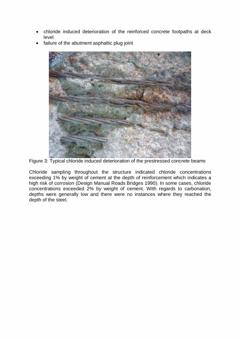
Figure 3: Typical chloride induced deterioration of the prestressed concrete beams
Chloride sampling throughout the structure indicated chloride concentrationsexceeding 1% by weight of cement at the depth of reinforcement which indicates ahigh risk of corrosion (Design Manual Roads Bridges 1990). In some cases, chlorideconcentrations exceeded 2% by weight of cement. With regards to carbonation,depths were generally low and there were no instances where they reached thedepth of the steel.
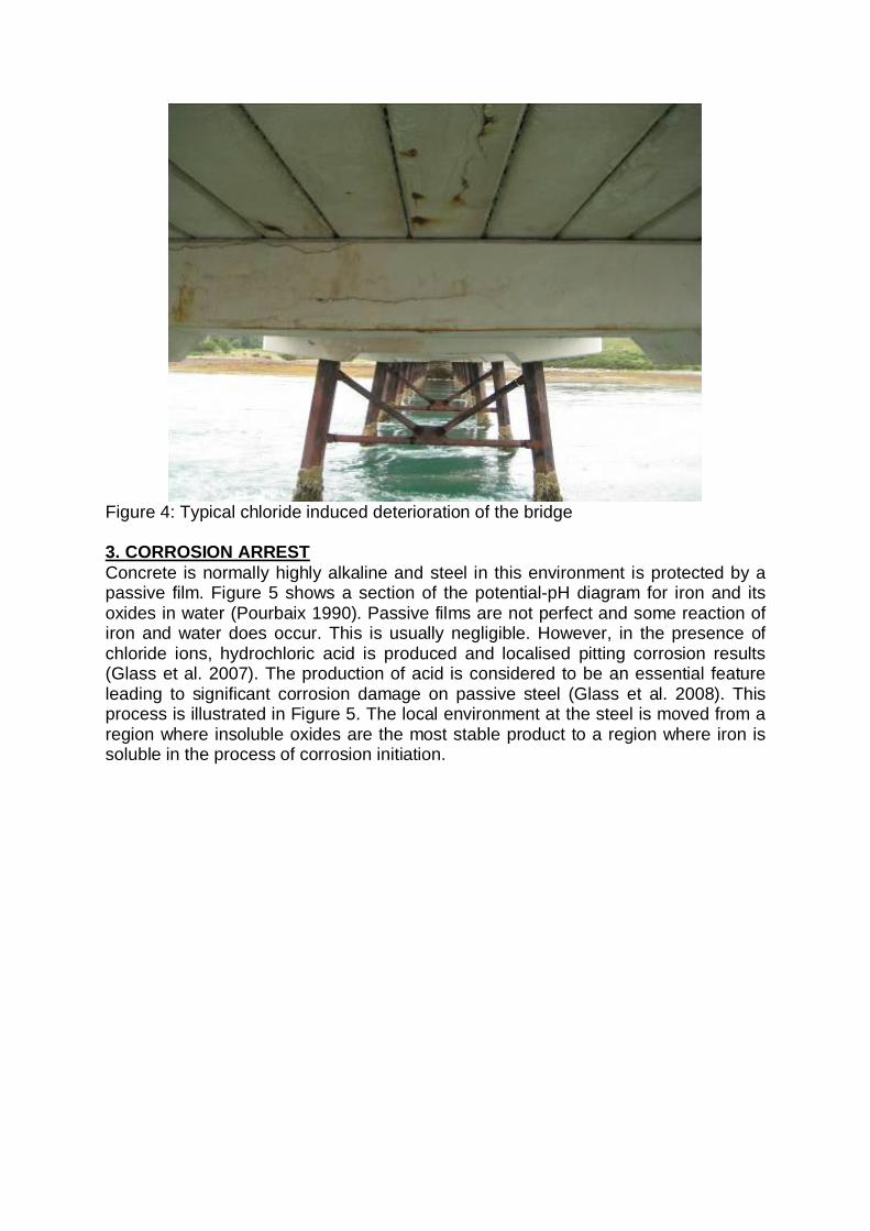
Figure 4: Typical chloride induced deterioration of the bridge
3. CORROSION ARRESTConcrete is normally highly alkaline and steel in this environment is protected by apassive film. Figure 5 shows a section of the potential-pH diagram for iron and itsoxides in water (Pourbaix 1990). Passive films are not perfect and some reaction ofiron and water does occur. This is usually negligible. However, in the presence ofchloride ions, hydrochloric acid is produced and localised pitting corrosion results(Glass et al. 2007). The production of acid is considered to be an essential featureleading to significant corrosion damage on passive steel (Glass et al. 2008). Thisprocess is illustrated in Figure 5. The local environment at the steel is moved from aregion where insoluble oxides are the most stable product to a region where iron issoluble in the process of corrosion initiation.

Figure 5: Model of corrosion initiation and arrest showing the stability of iron and itscorrosion products (Pourbaix 1990).
A powerful and very popular repair technique to arrest deterioration due to chlorideinduced corrosion is the use of Impressed Current Cathodic Protection (ICCP). Thetechnique relies on the passage of an electric current through the electrolyte to thecorroding metal surface and reverses the direction of the electric current producedby the corrosion reactions. It has a proven track record and it has been usedworldwide to protect reinforced concrete structures from future chloride induceddeterioration (Broomfield 2007, Concrete Society 2011).
One of the effects of an electrochemical treatment is also to produce hydroxyl ionson the steel raising the pH. The local environment at the steel is then moved from aregion where iron is soluble to a region where insoluble oxides are the most stableproduct. This has been proven to provide sustained protective effects to the steelreinforcement even when the protective current has been interrupted and chloridecontamination remains (Christodoulou et al. 2010, Christodoulou et al. 2012). Thisre-alkalisation process is also illustrated in Figure 5 and would lead to a restorationin steel passivity. It is termed pit re-alkalisation when localised pitting corrosion isarrested (Glass et al. 2008).
However, for prestressed steel the use of electrochemical treatments poses a risk ofhydrogen embrittlement (BSI 2012). The steel becomes brittle due to theincorporation of hydrogen so inducing stress corrosion cracking and leading topremature failure of the steel. This effect occurs on high strength stressed steeltendons such as prestressed or post-tensioned tendons.
Standards deal with such risks by limiting the induced change in the potential of thesteel reinforcement. For prestressed steel, the potential of the steel is limited tovalues more positive than -900 mV vs Ag/AgCl/0.5M KCl (Silver/Silver Chloride) (BSI2012). This limit aims to reduce the amount of hydrogen generated as a result of

water hydrolysis during the application of an electrochemical treatment such asICCP. However the risk to the asset owner remains throughout the long-term use ofan ICCP system. An impressed current treatment, delivered using an external DCpower supply to re-alkalise the acidic corrosion sites may be applied with a limitedduration (typically 3 months) to reduce this risk.
An analysis of the available literature shows that applied charge densities of lessthan 100kC/m2 would be sufficient to induce a change in the environment at the steelleading to the arrest of the corrosion process in chloride contaminated concrete(Glass and Buenfeld 1995, Polder et al. 2009, Glass et al. 2004).
Such a charge may be delivered using a sacrificial metal as an impressed currentsacrificial anode. Thus the temporary electrochemical treatment may be delivered ina relatively short period using a sacrificial (galvanic) anode and a power supply.Following the initial treatment, the anodes are connected in a galvanic cellarrangement to the reinforcement and a galvanic current is delivered from theanodes to ensure sustained steel passivity. This two-phase treatment is referred toas a hybrid electrochemical treatment.
The use of a hybrid electrochemical treatment on this particular structure wasadvantageous as there is no longer a need for removing physically sound butchloride contaminated concrete from behind the prestressing tendons which wouldhave otherwise caused structural weakening.
4. METHODOLOGYThis section describes the installation procedure, materials used and testingmethods for assessing the performance of the hybrid electrochemical treatment.
4.1 Installation MethodsOnly physically deteriorated concrete was removed from the prestressed concretebeams. Hybrid anodes 18mm in diameter and 37mm long were installed in drilledcavities between the prestressing tendons of the beams. The pre-drilled cavitieswere filled with proprietary low strength mortar to fully cover the anodes and provideseparation from the repair concrete (Figure 6).
The hybrid anodes included an integral titanium wire to facilitate the delivery of animpressed current and were connected in a series for each repair. Each series ofanodes for the individual repairs was terminated in a junction box which alsofacilitated a connection to the steel reinforcement. This provided a convenientlocation to connect them to the temporary power supply for delivering the initialcurrent treatment and later connecting them together in a galvanic cell.

Figure 6: Hybrid anode installation on a prestressed concrete beam
4.2 MaterialsTable 1 describes the details of the anode and concrete repair materials used. Forcommercial reasons the materials cannot be named directly and only their locationand characteristics are presented.
Table 1: Repair materials detailsMaterial Repair location CharacteristicsHybridAnodes
Prestressed ConcreteBeams
Discrete zinc anodes, 18mm diameterand 37mm long
Repairconcrete
Prestressed ConcreteBeams and ReinforcedConcrete Crossbeams
Dry sprayed polymer modified micro-concrete
4.3 Testing methodsThe assessment of the performance of the hybrid anodes was based on:
corrosion rates potential measurements
Corrosion rates are commonly measured using the polarisation resistance methodand they are usually expressed as a current density, a rate of weight loss or a rate ofsection loss (Polder et al. 1993, Andrade and Alonso 2004). A corrosion currentdensity of 1 mA/m2 is approximately equal to a steel section loss of 1 µm/year. Ingeneral, corrosion current densities higher than 1–2 mA/m2 are considered to besignificant.

Corrosion current densities are calculated based on the applied current and theachieved potential shift. A small current density applied to the steel produces a steelpotential shift and a voltage drop (IR drop) through the concrete (Christodoulou et al.2010). The potential shift and applied current density are inserted into the Butler–Volmer equation, which provides the basis for polarisation resistance theory, tocalculate the corrosion current density (Figure 7). It has previously been shown theacceptance criteria based on low steel corrosion rates are strongly related toacceptance criteria based on a minimum potential shift (Glass et al. 1997).
Figure 7: Example corrosion current density calculation (Christodoulou et al. 2010)
Measuring steel potentials against the potential of a standard reference electrode isa well established non-destructive monitoring technique (Concrete Society 2004,ASTM 2009). Following the application of an electrochemical treatment, steelpotentials should move towards less negative values. Such an approach is adoptedby Australian Standards (AS 2008).
Permanent MnO2 (manganese dioxide) reference electrodes were embedded withinthe repairs in order to measure the steel potentials. Readings of steel potentials weretaken after the initial high charge treatment had been completed and the anodeshave been switched to galvanic mode.
5. RESULTSFigure 8 illustrates typical monitoring data for the charge density delivered by thehybrid anodes on a repair of a prestressed concrete beams. The minimum chargedensity was set at 50 kC/m2 delivered over a period of 8 weeks or approximately 60days. The results presented here are typical and similar data were obtained for allthe repairs monitored.

Figure 8: Typical charge density and current applied to a repair area on aprestressed concrete beam.
Figure 9 illustrates the corrosion current density of four monitoring locations beforeand after the application of the treatment. It can be observed that in all four cases thecorrosion rate dropped below the required threshold and has since remained belowit. In addition, it can be observed that steel potentials have risen over time to lessnegative values indicating steel passivity.

Figure 9: Corrosion rates before and after the application of the hybrid cathodicprotection treatment.
6. DISCUSSIONHybrid cathodic protection is an attractive alternative to traditional electrochemicaltreatments. In the particular case study examined, it has been successfully applied toarrest corrosion of prestressed concrete beams. The initial high charge treatmentwas only over a brief period of time (typically. 8 to 12 weeks) and took place duringthe refurbishment works on the bridge, i.e. at a time where the application can becontinuously monitored. Daily readings of the voltage and current applied indicatedthat the steel potentials during the initial treatment never exceed the limits forprestressed steel (BSI 2012). This presents a significant reduction of embrittlementrisk when compared to traditional electrochemical treatments.
The corrosion monitoring data shows that the use of hybrid anodes with an initialbrief high charge electrochemical treatment resulted in a substantial decrease in thecorrosion rate, to a point where the prestressing tendons in the repair areas can nowbe considered to be passive.
Following the initial high charge treatment, low density galvanic cathodic protectionhas been sufficient to maintain the corrosion rates below the required threshold.Monitoring of the steel potentials over a period of up to 600 days has also confirmedthat the steel is passive. It has been observed that over-time steel potentials havebeen moving towards more positive values which is an indication of steel passivity.Most importantly, passivity has been maintained despite the continuous exposure ofthe bridge to an aggressive marine environment.
7. CONCLUSIONSIt can be concluded that:
Hybrid corrosion treatment can be successfully applied to prestressedconcrete and offer significant benefits over traditional electrochemicaltreatments.
Following the application of the brief high current electrochemical treatment,corrosion rates have dropped below a threshold value of 2 mA/m2 and haveremained as such for more than 600 days and continue to do so. This isdespite the continuous exposure of the bridge to an aggressive marineenvironment.
8. REFERENCESAmerican Society for Testing and Materials 2009, ASTM C 876 - 2009, StandardTest Method for Corrosion Potentials of Uncoated Reinforcing Steel in Concrete,West Conshohocken, Pennsylvania, USA.
Andrade C. and Alonso C. 2004, Test methods for on-site corrosion ratemeasurement of steel reinforcement in concrete by means of the polarisationresistance method, RILEM TC 154-EMC: electrochemical techniques for measuringmetallic corrosion, Materials and Structures, 37, pp. 623–643.
Australian Standards 2008, AS 2832.5, Cathodic protection of metals – Steel inConcrete Structures.

British Standards Institution, 2012. BS EN ISO 12696:2012, Cathodic protection ofsteel in concrete, London: BSI.
Broomfield J.P. 2007, Corrosion of steel in concrete: understanding, investigationand repair, 2nd ed., UK: Taylor & Francis.Christodoulou C., Glass G., Webb J., Austin S. and Goodier C. 2010, Assessing thelong term benefits of Impressed Current Cathodic Protection, Corrosion Science, 52,pp. 2671 – 2679 DOI: 10.1016/j.corsci.2010.04.018
Christodoulou C., Goodier C., Austin S., Glass G. and Webb J. 2012, On-sitetransient analysis for the corrosion assessment of reinforced concrete, CorrosionScience, 62, pp. 176 – 183 DOI information: 10.1016/j.corsci.2012.05.014
Concrete Society 2004, Technical Report 60, Electrochemical tests for reinforcementcorrosion, Surrey, UK.
Concrete Society 2011, Technical Report 73, Cathodic Protection of Steel inConcrete, Surrey.
Design Manual for Road and Bridges, Volume 3, Section 3, Part BA 35/1990Inspection and Repair of Concrete Highway Structures, Departmental Standard, UK.
Glass G. K. and Buenfeld N. R. 1995, On the current density required to protect steelin atmospherically exposed concrete structures, Corrosion Science, 37, pp. 1643 -1646.
Glass G.K., Davison N. and Roberts A. 2008, Hybrid Electrochemical TreatmentApplied To Corrosion Damaged Concrete Structures, Transportation ResearchBoard, 87th Annual Meeting, Washington DC.
Glass, G. K., Hassanein, A. M. and Buenfeld N. R. 1997, Monitoring the passivationof steel in concrete induced by cathodic protection, Corrosion Science, 39(8) pp.1451-1458.
Glass G.K., Reddy B. and Clark L.A. 2007, Making reinforced concrete immune fromchloride corrosion, Proceedings of the Institution of Civil Engineers, ConstructionMaterials, 160, pp. 155 – 164.
Glass G. K., Roberts A. C. and Davison N. 2004, Achieving high chloride thresholdlevels on steel in concrete, Corrosion 2004, NACE, Paper No. 04332.
Polder R.B., Peelen W.H.A., Stoop B.T.J and Neeft E.A.C. 2009, Early stagebeneficial effects of cathodic protection in concrete structures, Eurocorr 2009, Paper8408.
Polder R., Tondi A. and Cigna R., Concrete Resistivity and Corrosion Rate ofReinforcement, TNO Report 93-BT-r0170, TNO Delft, 1993.
Pourbaix M. 1990, Thermodynamics and Corrosion, Corrosion Science, 30, pp. 963– 988.