hybrid aerial and scansorial robotics - university of...
TRANSCRIPT

Hybrid Aerial and Scansorial Robotics
Alexis Lussier Desbiens, Alan Asbeck, and Mark Cutkosky
Abstract— We present an approach that builds upon previousdevelopments in unmanned air vehicles and climbing robots andseeks to emulate the capabilities of bats, insects and certainbirds that combine powered flight with the ability to land andperch on sloped and vertical surfaces. As it approaches a wall,the plane executes an intentional pitch-up maneuver to shedspeed and present its feet for landing. On contact, a nonlinearsuspension dissipates the remaining kinetic energy and directsinteraction forces toward the feet to engage small asperities onsurfaces such as brick or concrete. The focus of the work in thispaper is on the controller used for sensing a wall and executingvertical landing and take-off procedures and on the mechanismsdeveloped for spine engagement and disengagement.
I. INTRODUCTION
In comparison to other small robots, unmanned air vehicleshave the ability to travel very rapidly to remote locations,including sites such as the tops of buildings or bridges thatare hard to reach with terrestrial robots. However, they aresubject to a severe tradeoff between payload and mission life.In contrast, climbing robots can remain perched at remotesites for hours or days, providing a secure, stable platformfor inspection or surveillance. The work described in thispaper is aimed at combining the best attributes of aerial andvertical surface (scansorial) robots. We focus on landing andperching on vertical surfaces for a couple of reasons. Verticalsurface landing allows us to use gravity to slow the plane andengage gripping mechanisms. Also, vertical surfaces tend tobe relatively safe, unobtrusive and uncluttered locations forsheltering a small, fragile vehicle – particularly if it can takeshelter under the eaves of a building.
Our work builds upon developments in acrobatic maneu-vers for small unmanned air vehicles and on climbing robotsthat attach to vertical surfaces using arrays of miniaturespines. In other recent publications we describe the dynamicmodel of the plane and its highly damped, nonlinear suspen-sion that dissipates kinetic energy on landing and directsinteraction forces toward the spines to engage them [1],[2]. In this paper we focus on a new controller used forpowered landings and takeoffs from vertical surfaces andon a new spine engagement and disengagement mechanismneeded for reliably taking off from the wall. We demonstratethe overall approach used for scansorial landing, perchingand take-off, and conclude with a discussion of future workneeded to improve the robustness of the system with respectto disturbances (e.g. wind gusts). Future developments will
Alexis Lussier Desbiens and Alan Asbeck are Ph.D. Candidates inMechanical Engineering and Electrical Engineering at Stanford University,Stanford, USA {alexisld, aasbeck}@stanford.edu
Mark Cutkosky is Professor of Mechanical Engineering at StanfordUniversity, Stanford, USA [email protected]
address landing on sloped and horizontal surfaces and onmechanisms for crawling along the surface after landing. Anaccompanying video shows the landing, perching and take-off sequence, highlighting the contributions of the controllerand compliant spine engagement/disenagement systems.
II. PREVIOUS WORK
The work described in this paper draws upon previouswork on small aerial platforms that execute maneuverssuitable for landing and perching, climbing robots, and bio-logical studies of creatures that combine aerial and scansorialcapabilities.
A. Perching and takeoff maneuvers
Several researchers have demonstrated approaches bywhich a small plane can execute the maneuvers needed toland and perch on a target such as a branch or pole. Some ofthe initial work in this field includes [3] on indoor hoveringand level flight and how to transition back and forth betweenthese states as well as methods for autonomous landing andtakeoff from a specially designed stand. An accurate motioncapture system was used to estimate the states of the airplaneand control was done using an off-board computer. Recentwork [4] has used a similar motion capture system to learna highly accurate model of the aerodynamics of a smallglider. This model was used to demonstrate perching on awire using a pitch-up maneuver to slow the airplane beforecontact. Further work has demonstrated [5] that, at least for aglider, there is a lack of controllability at very low speeds. Adifferent approach involving a plane with morphing geometry[6] provides more control at low speeds. A variation on thisapproach is undergoing wind tunnel testing [7].
Much of the initial work on developing controllers andtrajectories for dynamic perching has taken advantage ofoff-board motion capture and control sysems. However, thecapabilities of lightweight onboard sensing and control sys-tems are also improving. Work on autonomous hovering [8]made use of a 30g Microstrain IMU (3-axis attitude sensor)to control the attitude of the plane and transition betweenregular flying and hovering. Other lightweight sensors [9]and autopilot boards, like the Paparazzi open-source autopilot[10], are becoming available, providing a basis autonomousperching and takeoff.
B. Climbing robots
From the literature on climbing robots, light weight andlow-power technologies for climbing vertical surfaces areparticularly relevant. The work described here utilizes the mi-crospine technology developed for Spinybot [11] and RISE
2010 IEEE International Conference on Robotics and AutomationAnchorage Convention DistrictMay 3-8, 2010, Anchorage, Alaska, USA
978-1-4244-5040-4/10/$26.00 ©2010 IEEE 72

Fig. 1. Sequence of the plane performing a powered perching maneuver on a concrete wall. The plane is initially flying around 10 m/s, detects the wallat 6m and iniates a pitch up. The motor is turned off as soon as touchdown is possible, and the plane generally contacts the wall while moving at 0-2.7m/sin the horizontal direction. The landing gear finally absorbs the impact and engages the spines. The entire process takes < 1 sec.
[12] to climb a variety of vertical surfaces including concrete,stucco and brick. The miniature spines perch on asperities(small bumps and pits) on the surface and a compliantsuspension promotes spine engagement and ensures that theoverall load is distributed among the spines. The spineshave the advantages that they are lightweight, passive, andrelatively unaffected by dirty or dusty surfaces. They can beused for thousands of attachment/detachment cycles and donot leave any trace of their passage.
C. Hybrid platforms
Relatively few hybrid aerial/terrestrial platforms havebeen demonstrated. However, one early example is a fly-ing/walking platform [13] that combines a small flexiblewing MAV with the Whegs technology from CWRU. Al-though not able to perch, it can land on horizontal surfaces,fold its wings and crawl. The USAF Academy has alsoinvestigated innovative concepts for flying and perching [14].Their most successful concept was a plane equipped with asticky pad at the nose. After flying into a wall, the planehangs from the sticky pad by a tether, which can be cut toresume flight. Our own approach began with an investigationof strategies for landing and attaching to vertical walls usingspines. In previous papers [1], [2] we present the dynamicmodel of the airplane with its highly compliant and dampedlanding gear that prevents it from bouncing off the wall andpromotes attachment of microspines.
D. Aerial/Scansorial Biological Systems
Many animals including birds, insects, bats, and flyingsquirrels and lizards have the ability to fly or glide to a desti-nation and perch. However, there is comparatively little workon the details of landing and take-off. The flying squirrelcan land on vertical tree trunks using a maneuver somewhatlike that of our plane. Its stretched skin flaps provide a lowaspect ratio wing that provides aerodynamic stability and liftat angles of attack up to 40 degrees. It has been shown thatthe squirrels deliberately stall themselves prior to impact,allowing them to reduce by 60% their horizontal velocity,while spreading the impact over all four limbs [15], [16].As for takeoff, it has been shown that pigeons generate up
to 2.3g of acceleration with their legs prior to the start offlapping flight [17]. This initial jump allows them to increasetheir initial speed and clear obstacles for their wings. At amuch smaller scale, flies make dramatic use of their legs forbecoming airborne, using different strategies for voluntaryand emergency takeoffs [18].
III. SYSTEM OVERVIEW
Our approach uses an aerobatic plane to fly toward thewall, intentionally pitch up just before impact to slow down,and dissipate the remaining kinetic energy with a suspensionthat keeps forces on the microspine toes within a saferegion, as shown in figure 1. The details of the perchingstrategy implemented on a glider can be found in [1]. Thislanding method allows the plane to approach the wall at itsnormal flying speed. Once the plane has pitched up, it isessentially ballistic. The entire maneuver requires < 0.75s,which minimizes the effects of disturbances.
The airframe that we are using (fig. 2 left) is a modifiedFlatana airplane, with a brushless motor and 9x3.8 APC pro-peller, to which we added a Paparazzi autopilot [10], 3-axisaccelerometer (ADXL335), 3-axis gyroscope (IDG500) andultrasound sensor (Maxbotix MB1320) for wall detection.
We developed a highly compliant and damped suspension(fig. 2 center) to permit a relatively large envelope of initialcontact conditions: 0-2.7 m/s forward velocity, up to 3 m/sdownward velocity, and pitch angles from 50-110 deg. [2].The suspension has effectively three joints with bending atthe hip and knee and stretching at the spines. Each foot hasfive spines to share the load over several asperities.
The aircraft re-launches from a perched position intonormal flight. It uses a spine-release mechanism to disengagethe spines; then the thrust from the propeller moves theplane away from the wall backwards, in a manner similarto hovering flight.
IV. POWERED PERCHING
A multiple-exposure photograph illustrating the perchingsequence is shown in figure 1. In this figure, the plane isinitially flying around 10 m/s; it detects the wall at 6m andcommands a full up elevator to initiate the pitch up maneuver.
73

1
2
34
5
6
3cm
Fig. 2. Left, picture of the plane equipped with sensors and perching landing gear. Center, suspension to absorb energy while landing, including spine-release mechanism. Right, diagram of spine linkage. The spine is embedded in element 1, and can move compliantly due to flexures 3, 4, and 5. Thelinkage pivots around the hole in element 2.
As the pitch angle approaches 75 deg, the motor is turnedoff and the rotation of the airplane slowed down by theelevator. As the pitch approaches 90 deg, the plane’s flightis essentially ballistic and the plane contacts the wall whilemoving at roughly 2.5 m/s in the horizontal direction and2m/s in the downward direction. At impact, the landing gearabsorbs the remaining kinetic energy and engages the spines.
The strategy for powered perching is similar to that usedfor gliding perching in [1], but the addition of a motor andpropeller presents additional benefits and challenges. Themotor allows the plane to fly more slowly and at higherpitch angles, if desired, as it approaches the wall. Duringthe pitch-up maneuver, thrust from the propeller can be usedto extend the region in which the plane is ready to contactthe wall. However, with the propeller in the front of theaircraft, power must be cut before the plane hits the wall.In our implementation, the propeller is de-powered as theaircraft reaches a pitch angle of 75 deg., providing somethrust through the pitch-up phase and allowing the propellerto passively slow down and stop rotating before wall contact.If the propeller is stopped suddenly, the change in angularmomentum will cause the aircraft to roll (in level flight) andthen yaw as the plane pitches up. We stop the propeller earlyand slowly during the maneuver, while the velocity of theplane is still high, so that the control surfaces can compensatefor the change in angular momentum.
A powerful ultrasonic sensor (Maxbotix MB1320) is nowused, as the LV-EZ2 was sensitive to the acoustical noisecreated by the propeller. Unfortunately, the new sensor has anupdate rate of only 10 Hz, which prevents us from obtainingmultiple measurements of the wall position before triggeringthe maneuver. Multiple measurements would be useful asthe plane could confirm the wall’s presence and computethe approach velocity. Currently, we assume the approachvelocity is around 10m/s, and, after our first detection ofthe wall, trigger the maneuver after an appropriate delay.Ultimately, an optical or vision-based sensor may be moreuseful in providing good velocity information.
Figure 3 shows the plane’s velocity during a landingmaneuver performed in the air, to observe the trajectorywithout the influence of the wall. After the plane pitchesup, gravity acts quickly in the y-direction, decreasing thevelocity. The plane is only able to land if the x- and y-velocities are both within acceptable ranges, which onlyoccurs for a short period of time (around 0.15 sec). Thisshort time corresponds to a need to sense the distance to thewall with an accuracy of ±20cm.
Fig. 3. Plot of plane’s x- and y-velocities during a landing maneuverperformed in the air. The plane is within the envelope of possible vx andvy for landing during only a short time. Data plotted was extracted from avideo of the plane at 30 frames/sec.
V. TAKEOFF
Various strategies can be used to take off from vertical sur-faces depending on the airframe configuration, its orientationon the wall and the complexity of the takeoff mechanism.For example, an airplane with a low thrust-to-weight (T/W)ratio would probably benefit from a jumping mechanism(as in [19]) to increase its initial speed and reorient itselffor flight. Although we are ultimately interested in lowT/W airframes for efficiency reasons, we describe here an
74
approach used with an acrobatic platform with T/W > 1.Such a platform has the possibility to hover briefly, buildinghorizontal velocity before resuming normal flight. Althoughless efficient, this strategy allows for a smooth and controlledtakeoff and prevents any loss of elevation in tight spaces. Weanticipate that future work with low T/W planes will be ableto incorporate some of the same components and methodsthat we describe here.
Our approach consists of releasing the spines using aspecially designed mechanism and starting the takeoff oncefree from the wall. Then, using the high T/W ratio andpropwash over its control surfaces, the airplane holds its noseup and away from the wall to build horizontal speed beforeresuming flight.
The use of microspines with a compliant suspension hasthe advantage of not requiring any special fixtures to land on,but also produces some challenges during takeoff. Althoughthe spines will tend to disengage when the tangential load(due to gravity) is removed, the suspension is sufficientlycompliant that a large excursion is required to unload thespines. If the propeller is used to generate upward thrust, thespines tend to act as a pivot, around which the plane rotatesuntil the propeller hits the wall. Furthermore, any differencesin the timing of release of the spines will cause the plane toyaw and possibly roll as the propeller pulls the plane awayfrom the wall. For these reasons, it was decided to add anactive mechanism to retract the spines on command.
A. Spine release mechanism
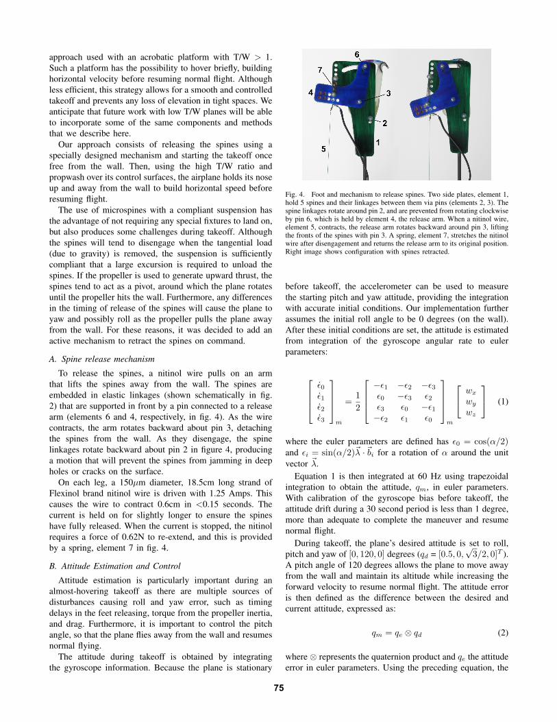
To release the spines, a nitinol wire pulls on an armthat lifts the spines away from the wall. The spines areembedded in elastic linkages (shown schematically in fig.2) that are supported in front by a pin connected to a releasearm (elements 6 and 4, respectively, in fig. 4). As the wirecontracts, the arm rotates backward about pin 3, detachingthe spines from the wall. As they disengage, the spinelinkages rotate backward about pin 2 in figure 4, producinga motion that will prevent the spines from jamming in deepholes or cracks on the surface.
On each leg, a 150µm diameter, 18.5cm long strand ofFlexinol brand nitinol wire is driven with 1.25 Amps. Thiscauses the wire to contract 0.6cm in <0.15 seconds. Thecurrent is held on for slightly longer to ensure the spineshave fully released. When the current is stopped, the nitinolrequires a force of 0.62N to re-extend, and this is providedby a spring, element 7 in fig. 4.
B. Attitude Estimation and Control
Attitude estimation is particularly important during analmost-hovering takeoff as there are multiple sources ofdisturbances causing roll and yaw error, such as timingdelays in the feet releasing, torque from the propeller inertia,and drag. Furthermore, it is important to control the pitchangle, so that the plane flies away from the wall and resumesnormal flying.
The attitude during takeoff is obtained by integratingthe gyroscope information. Because the plane is stationary
Fig. 4. Foot and mechanism to release spines. Two side plates, element 1,hold 5 spines and their linkages between them via pins (elements 2, 3). Thespine linkages rotate around pin 2, and are prevented from rotating clockwiseby pin 6, which is held by element 4, the release arm. When a nitinol wire,element 5, contracts, the release arm rotates backward around pin 3, liftingthe fronts of the spines with pin 3. A spring, element 7, stretches the nitinolwire after disengagement and returns the release arm to its original position.Right image shows configuration with spines retracted.
before takeoff, the accelerometer can be used to measurethe starting pitch and yaw attitude, providing the integrationwith accurate initial conditions. Our implementation furtherassumes the initial roll angle to be 0 degrees (on the wall).After these initial conditions are set, the attitude is estimatedfrom integration of the gyroscope angular rate to eulerparameters:
ε̇0ε̇1ε̇2ε̇3
m
=12
−ε1 −ε2 −ε3ε0 −ε3 ε2ε3 ε0 −ε1−ε2 ε1 ε0
m
wx
wy
wz
(1)
where the euler parameters are defined has ε0 = cos(α/2)and εi = sin(α/2)~λ ·~bi for a rotation of α around the unitvector ~λ.
Equation 1 is then integrated at 60 Hz using trapezoidalintegration to obtain the attitude, qm, in euler parameters.With calibration of the gyroscope bias before takeoff, theattitude drift during a 30 second period is less than 1 degree,more than adequate to complete the maneuver and resumenormal flight.
During takeoff, the plane’s desired attitude is set to roll,pitch and yaw of [0, 120, 0] degrees (qd = [0.5, 0,
√3/2, 0]T ).
A pitch angle of 120 degrees allows the plane to move awayfrom the wall and maintain its altitude while increasing theforward velocity to resume normal flight. The attitude erroris then defined as the difference between the desired andcurrent attitude, expressed as:
qm = qe ⊗ qd (2)
where ⊗ represents the quaternion product and qe the attitudeerror in euler parameters. Using the preceding equation, the
75

attitude error can be calculated with:
qe =
ε0 −ε1 −ε2 −ε3ε1 ε0 −ε3 ε2ε2 ε3 ε0 −ε1ε3 −ε2 ε1 ε0
m
ε0−ε1−ε2−ε3
d
(3)
The attitude error in euler parameters (qe) can then beconverted to roll, pitch and yaw errors. Care must be takenduring this last conversion as it is singular for a pitch error of±90 degrees. Fortunately, with a good controller and carefulsetting of the desired attitude, this situation can be avoided.The roll, pitch and yaw errors are then controlled using theaileron, elevator and rudder. Three lead controllers are used,which have the form:
Ki(s) = ki ×s+ 5.3s+ 26.5
(4)
where the gain ki is adjusted for each controller.
C. Control Sequence
The control sequence is illustrated in figure 6. The se-quence starts by estimating the attitude using gravity mea-surement from the accelerometer, and resetting the gyro bias.After this initialization step, the ailerons are commanded to±30 degrees of trim, the attitude control is enabled and thepropeller is slowly ramped up to a thrust to weight (T/W)ratio slightly below 1.0. This prevents the plane from fallingtoo quickly when the spines are released.
Reset Gyro BiasRoll = 0, Pitch = 90 deg
Yaw = measured from accel.
T/W ratio slightly < 1Aileron trim ± 30 degAttitude Control ON
Release spines ON
T/W ratio > 1
Release spines OFF
!t > 2 sec
!t > 0.15-0.25 sec
!t > 0.05 sec
Resume normal flight
On the wall
Fig. 6. Control sequence and timing during takeoff. The spines can bereleased between 0.15 and 0.25 seconds to control how much vertical heightis lost during the maneuver.
When ready for takeoff, the spines are released. The nitinolwire mechanism retracts the spines in about 150 millisecondsand the T/W ratio can be increased soon after. It is generallydesirable to increase the T/W ratio as soon as the spines arereleased to help the spines in their disengaging motion andprevent any vertical drop and downward velocity. However,we have also experimented with a maximum delay of 250
milliseconds, which causes the plane to drag its feet for about20 cm on the wall before taking off.
The nitinol wire mechanism is turned off 50 millisecondsafter increasing in T/W ratio, but the spines are not readyfor any new engagements for another 0.5 seconds due to theslow cooling and relaxation of the nitinol. This delay helpsto ensure that the plane is sufficiently away from the wallthat the spines cannot inadvertently catch again.
D. Results
Numerous takeoffs have been performed using the spinerelease mechanism and controller described in the previoussections. A typical takeoff sequence is illustrated in fig.5. In this case, the takeoff was delayed for an extra 250milliseconds after the spines were released. With a shorterdelay, it is possible to take off without any loss in elevation.On the accompanying video, it is possible to observe theplane dropping about 20 cm before the T/W ratio becomessufficient to propel the plane upward. One can also observethat the right leg is released slightly before the left one,causing an initial roll disturbance that is compensated forduring the maneuver. Overall, the maneuver illustrated infig. 5 lasts about 2 seconds, after which it is possible to doa 180-degree roll and resume normal flight.
VI. CONCLUSIONS AND FUTURE WORK
Autonomous landing and perching followed by takeoffhave been demonstrated on vertical surfaces. The approach isparticularly useful for landing on locations where horizontalsurfaces may be cluttered and where a runway for landingand takeoff is not available. Due in part to the use of a highlycompliant landing gear, an active spine release mechanismis needed to achieve reliable disengagement prior to takeoff.
Unlike on landing, on takeoff it is difficult to avoid a pe-riod of low-speed flight. (Even with a jump-assisted takeoff, aplane may need some time to achieve full airspeed.) Duringthis time, it is important to have accurate roll, pitch andyaw controllers to compensate for disturbances. Because theplane starts from a known stationary orientation, it sufficesto integrate gyroscope information to estimate the attitudeduring the ≈2 second maneuver.
Although a high thrust/weight ratio plane is less efficientthan conventional aircraft, it provides benefits in terms ofcontrollability in tight spaces during takeoff. Given that theplane only requires a straight line-of-sight approach to beable to land on a surface, it is ideal if the space requiredfor takeoff is no larger. The high thrust/weight ratio alsoprovides for a fail-safe approach on landing; if the spines failto engage, the plane can immediately switch to the takeoffprocedure and fly away from the wall for another attempt.Typically, however, the plane will grasp surfaces almostimmediately on landing. Therefore, sliding along the surfaceduring a failed landing should be easy to detect before theplane gathers too much downward velocity. Takeoff after ashort downward fall following spine release has already beendemonstrated, so this maneuver can be included directly.
76

Fig. 5. A multiple-exposure photograph of the takeoff sequence. The airplane is originally at rest on the wall with ailerons and elevator ready for takeoff.The propeller is then commanded to a T/W ratio slightly less than 1.0; spines are released and the T/W ratio is increased to about 1.08 as the pitch angleis controlled to approximately 120 degrees from horizontal. Note that the spines have been intentionally released early in this example to clearly illustratethis step, but with ideal timing no vertical drop is observed.
Looking ahead, a number of additional developments areneeded to provide a reliable hybrid aerial/scansorial platform.The ultrasonic sensor should be replaced or augmented withoptical sensing for greater reliability and the aircraft con-troller should be enhanced for more robust flying in ambientconditions. We are also interested in being able to crawl andmaneuver to reorient the plane on the wall after landing. Thiscapability will require the use of opposed pairs of spines thatcan grip when loaded in any direction (the current spinesgrip only when the plane is oriented nose-upward) and amore efficient spine disengagement mechanism that can beapplied with every step.
VII. ACKNOWLEDGMENTS
Alexis Lussier Desbiens is supported by the Natural Sci-ences and Engineering Research Council of Canada and theOrganization of American States, with additional supportfrom DARPA DSO. We would also like to thank the membersof BDML at Stanford for all their help in conducting theexperiments reported here. Many thanks to Dharma Tamm,Matthew Norcia and Kwame Agyei-Owusu for building somany prototypes over the summer.
REFERENCES
[1] A. Lussier Desbiens and M. Cutkosky, “Landing and Perching onVertical Surfaces with Microspines for Small Unmanned Air Vehicles,”2nd International Symposium on Unmanned Aerial Vehicles, 2009.
[2] A. Lussier Desbiens, A. Asbeck, and M. Cutkosky, “ScansorialLanding and Perching,” 14th International Symposium on RoboticsResearch, 2009.
[3] A. Frank, J. S. McGrew, M. Valenti, D. Levine, and J. P. How, “Hover,transition, and level flight control design for a single-propeller indoorairplane,” AIAA Guidance, Navigation and Control Conference, Aug2007.
[4] R. Cory and R. Tedrake, “Experiments in fixed-wing uav perching,”Proceedings of the AIAA Guidance, Navigation, and Control Confer-ence, Aug 2008.
[5] J. Roberts, R. Cory, and R. Tedrake, “On the controllability of fixed-wing perching,” American Controls Conference, Sep 2009.
[6] A. Wickenheiser and E. Garcia, “Perching aerodynamics and trajectoryoptimization,” Proceedings of SPIE, Jan 2007.
[7] G. Reich, M. Wojnar, and R. Albertani, “Aerodynamic Performace ofa Notional Perching MAV Design,” 47 th AIAA Aerospace SciencesMeeting, 2009.
[8] W. Green and P. Oh, “Autonomous hovering of a fixed-wing micro airvehicle,” IEEE International Conference of Robotics and Automation,2008.
[9] A. Baerveldt and R. Klang, “A low-cost and low-weight attitudeestimation system for an autonomous helicopter,” in 1997 IEEEInternational Conference on Intelligent Engineering Systems. Instituteof Electrical & Electronics Engineers (IEEE), 1997, p. 391.
[10] Paparazzi, “Paparazzi, the free autopilot,” 2008. [Online]. Available:http://paparazzi.enac.fr
[11] A. Asbeck, S. Kim, M. Cutkosky, W. R. Provancher, and M. Lanzetta,“Scaling hard vertical surfaces with compliant microspine arrays,”International Journal of Robotics Research, vol. 25, no. 12, p. 14,Sep 2006.
[12] M. Spenko, G. Haynes, J. Saunders, M. Cutkosky, A. Rizzi, andR. Full, “Biologically inspired climbing with a hexapedal robot,”Journal of Field Robotics, Feb 2008.
[13] R. J. Bachmann, F. J. Boria, P. G. Ifju, R. D. Quinn, J. E. Kline,and R. Vaidyanathan, “Utility of a sensor platform capable of aerialand terrestrial locomotion,” International Conference on AdvancedIntelligent Mechatronics, pp. 1581–1586, Aug 2005.
[14] M. Anderson, C. Perry, B. Hua, D. Olsen, J. Parcus, K. Pederson, andD. Jensen, “The Sticky-Pad Plane and other Innovative Concepts forPerching UAVs,” 47 th AIAA Aerospace Sciences Meeting, 2009.
[15] G. Byrnes, N. T.-L. Lim, and A. J. Spence, “Take-off and landingkinetics of a free-ranging gliding mammal, the malayan colugo (gale-opterus variegatus),” Proceedings of the Royal Society B: BiologicalSciences, vol. 275, no. 1638, pp. 1007–1013, Feb 2008.
[16] K. E. Paskins, A. Bowyer, W. M. Megill, and J. S. Scheibe, “Take-offand landing forces and the evolution of controlled gliding in northernflying squirrels glaucomys sabrinus,” Journal of Experimental Biology,vol. 210, no. 8, pp. 1413–1423, Apr 2007.
[17] F. H. Heppner and J. G. Anderson, “Leg thrust important in flighttake-off in the pigeon,” Journal of Experimental Biology, vol. 114,pp. 285–288, Mar 1985.
[18] G. Card and M. Dickinson, “Performance trade-offs in the flightinitiation of Drosophila,” Journal of Experimental Biology, vol. 211,no. 3, p. 341, 2008.
[19] M. Kovac, M. Fuchs, A. Guignard, J.-C. Zufferey, and D. Floreano,“A miniature 7g jumping robot,” International Conference onRobotics and Automation, pp. 373–378, 2008. [Online]. Available:http://ieeexplore.ieee.org/xpls/abs all.jsp?arnumber=4543236
77