hwp document - krs.westus.cloudapp.azure.com
TRANSCRIPT

2018
Guidance for
Floating LNG Bunkering Terminal
GC-25-E KR

2018
Guidance for
Floating LNG Bunkering Terminal
GC-25-E KR

- i -
APPLICATION OF
"Guidance for Floating LNG Bunkering Terminal"
1. Unless expressly specified otherwise, the requirements in the Guidance apply to Floating LNG Bunkering Terminal for which contracts for construction are signed on or after 1 July 2018.

- iii -
CONTENTS
CHAPTER 1 GENERAL ·······································································································1
Section 1 General ··············································································································· 1Section 2 Definitions ·········································································································· 2
CHAPTER 2 CLASSIFICATION AND SURVEYS ··························································5
Section 1 General ··············································································································· 5Section 2 Classification Survey ························································································· 5Section 3 Surveys ··············································································································· 7
CHAPTER 3 DESIGN CONDITION ···················································································9
Section 1 General ··············································································································· 9Section 2 Design Loads ····································································································· 9Section 3 Corrosion Control Means and Corrosion Margins ········································ 11Section 4 Risk Assenssment ··························································································· 12
CHAPTER 4 MATERIALS AND WELDING ···································································13
Section 1 General ············································································································· 13
CHAPTER 5 HULL CONSTRUCTION AND EQUIPMENT ········································15
Section 1 General ··········································································································· 15Section 2 Survival Capability and Location of Cargo Tanks ······································· 16Section 3 Longitudinal Strength ······················································································· 16Section 4 Structural Design and Analysis of the Hull ·················································· 17Section 5 Hull Arrangements ··························································································· 19Section 6 Hull Equipment ································································································ 19
CHAPTER 6 POSITIONING SYSTEM ············································································21
Section 1 General ············································································································· 21Section 2 Mooring Analysis ····························································································· 22Section 3 Design of Mooring Lines, etc. ······································································· 26Section 4 Mooring Equipment ························································································· 28Section 5 Single Pint Mooring Systems ········································································· 29Section 6 Anchor Holding Power ···················································································· 29
CHAPTER 7 MACHINERY INSTALLATIONS ·····························································33
Section 1 General ············································································································· 33Section 2 Piping Systems for Cargo Tanks ··································································· 33Section 3 Use of Natural Gas as Fuel ··········································································· 33
CHAPTER 8 ELECTRICAL EQUIPMENT AND CONTROL SYSTEMS ·················35
Section 1 Hazardous Area ································································································ 35Section 2 Electrical Equipment ························································································ 35Section 3 Control Systems ······························································································· 35
CHAPTER 9 VENTILATION ····························································································37
Section 1 General ············································································································· 37

- iv -
Section 2 Mechanical Ventilation in the Cargo Area ···················································· 38
CHAPTER 10 FIRE PROTECTION, FIRE EXTINCTION AND
MEANS OF ESCAPE ···············································································41
Section 1 Fire Protection and Fire Extinction ································································ 41Section 2 Means of Escape ····························································································· 41
CHAPTER 11 PERSONNEL PROTECTION ·································································43
Section 1 Personnel Protection ························································································· 43
CHAPTER 12 BUNKERING SYSTEM ············································································45
Section 1 General ············································································································· 45Section 2 Arrangement and Design of Bunkering Systems ·········································· 45Section 3 Bunker Transfer Systems ················································································ 47Section 4 Control, Monitoring and Safety Systems ······················································· 48Section 5 Communication and Lighting Systems ··························································· 50Section 6 Operation Requirements ··················································································· 50
Ch 1 General Ch 1
Guidance for Floating LNG Bunkering Terminal 2018 1
CHAPTER 1 GENERAL
Section 1 General
101. Application
1. This Guidance is applied to the surveys, design, hull structures, hull equipment and machinery in-stallations of a floating liquefied natural gas (to be referred to as “LNG” hereinafter) bunkering ter-minal where floating LNG bunkering terminal (to be referred to as “terminal” hereinafter) refers to a barge that moors permanently or for a long period on the specific waters where it is to be in-stalled and stores LNG transported in by ships carrying liquefied gas in bulk and unloads it to the receiving vessels.
2. This Guidance is the minimum requirement of Society and is to be in compliance with the interna-tional conventions and the laws of the country that holds jurisdiction over the waters where the ter-minal is to be operated. If the international conventions and the regulations of the country with ju-risdiction are stricter than the provisions of this Guideline, the international conventions and the regulations of the country with jurisdiction shall be followed.
102. Class notations
1. Ships which comply with this Chapter may be assigned with the ’LNG Bunkering Terminal’ nota-tion as an additional installation notation at the request of the owner
2. Where a ship assigned the ’LNG Bunkering Terminal’ notation incorporates systems for handling of excess vapor return from the receiving ship, VRS notation may be assigned in accordance with the followings. (1) The capacity of vapor recovery expressed in kW is assigned next to VRS. For example, where
the capacity is [X] kW, the notation will be assigned as VRS[X].(2) Requirements for the notation is to be in accordance with Ch 12, 205..
103. Equivalence and novel features
1. The construction and equipment, etc. which are not in compliance with the requirements of the Guidance but are considered to be equivalent to those required in the Guidance will be accepted by the Society.
2. The Society may consider the classification of the construction and equipment based on or applying novel design principles or features, to which the Rules are not directly applicable, on the basis of experiments, calculations or other supporting information provided to the Society.
3. For specific equipment, components and systems, the requirements of alternative standards or other recognized standards can be followed in place of the requirements of this Guideline.
4. The risk evaluation of 104. may be applicable for justification of equivalence or novel features.
104. Risk evaluation
1. A risk evaluation is to be carried out to identify significant hazards and accident scenarios that may affect the installation or any part thereof, and consider the benefit of existing or potential risk control options.
2. The objective of the risk evaluation is to identify areas of the design that may require the im-plementation of risk control measures to reduce identified risks to an acceptable level. For this pur-pose, a systematic process is to be applied to identify situations where a combination or sequence of events could lead to undesirable consequences such as property damage, personnel safety and en-vironmental damage at an acceptable frequency.
3. The risk assessment is to consider the following events as a minimum.(1) Damage to the primary structure due to extreme weather, impact and collision, dropped objects,

Ch 1 General Ch 1
2 Guidance for Floating LNG Bunkering Terminal 2018
helicopter collision, exposure to unsuitably cold temperature, exposure to high radiant heat(2) Fire and explosion(3) Damage of primary liquid containment(for a duration to be determined based on an approved
contingency plan)(4) Leakage of liquefied gas(5) Release of flammable or toxic gas(6) Roll-over(7) Loss of stability(8) Loss of any single component in the station keeping and mooring system(9) Loss of ability to offload liquefied gas or discharge gas ashore(10) Loss of any one critical component in the liquefaction system(11) Loss of electrical power
4. The identified risk control options(prevention and mitigation measures) deemed necessary to be im-plemented should be considered part of the design basis of the unit.
5. Approval process of Risk-based design is to comply with Guidance for Approval of Risk-basedShip Design.
105. Codes and Standards
Notwithstanding the requirements of these guidelines, the following recognized international and in-dustry standards may apply.
Section 2 Definitions
201. Application
1. The definitions of terms and symbols which appear in the Guidance are to be as specified in this Section, unless otherwise specified, and definitions of terms and symbols not specified in the Guidance are to be as specified in Rules for Pt 7, Ch 5 of Rules for the Classification ofSteel Ships, Guidance for Floating Production Units and Guidance for Floating LiquefiedGas Units.
202. Definitions
1. Bunkering means to the transfer of liquid or gas fuel from an onshore or floating facility to a fixed or mobile tank connected to the fuel supply system of a ship.
2. Bunkering systems means to an interface between a ship and a facility for LNG bunkering.
Standard No. Title of Standard
SGMF Gas as a Marine Fuel – Bunkering safety guideline
SIGTTO Bunkering ship/ onshore terminal system for quick blocking and LNG transfer ships USC G(CG-OES) Policy Letter No.01-15
Guidelines for LNG fuel transfer operations and training of personnel on vessels using natural gas as fuel
USC G(CG-OES) Policy Letter No.02-15
Guideline related to vessels and waterfront facilities conducting LNG marine fuel transfer (bunkering) operations
OCIMF/SIGTTO Guideline on ship-to-ship LNG transfer
ISO 16904 Petroleum and natural gas industries – Design and testing of LNG marine transfer arms for conventional onshore terminals
EN 1474-2 Installation and equipment for LNG – Design and testing of marine transfer systems –
Design and testing of transfer hoses
EN 1474-3 Installation and equipment for LNG – Design and testing of marine transfer systems – Offshore transfer systems
IAPH Ship-to-ship LNG Bunkering Checklist
Ch 1 General Ch 1
Guidance for Floating LNG Bunkering Terminal 2018 3
It is applied to the terminal-to-ship, truck-to-ship or ship-to-ship bunkering scenarios. 3. Receiving ship means is the ship that receives LNG fuel.
4. Cargoes are products listed in Pt 7, Ch 5, Sec 19 of Rules for the Classification of SteelShips carried in bulk by ships.
5. Positioning systems are such systems to keep the unit at a specific position of designated serv-ice area permanently or for long periods of time, which are specified in the followings(1) Spread mooring systems consist of mooring lines connected to piles, sinkers, etc., which are
firmly embedded into the seabed, the other end of which is individually connected to winches, or stoppers which are installed on a unit, the definitions of each category being as given in the followings.(A) Catenary Mooring(CM) is defined as mooring forces obtained mainly from the net weight
of spreaded catenary mooring lines.(B) Taut Mooring(TM) is defined as mooring lines arranged straight and adjusted by high ini-
tial mooring forces, and the mooring forces obtained from the elastic elongation of these lines.
(2) Single point mooring system (SPM) is a system that allows a unit to weathervane so that the unit changes its heading corresponding to wind and wave directions. Typical SPM systems are as shown below:(A) Catenary Anchor Leg Mooring (CALM) consists of a large buoy connected to mooring
points at the seabed by catenary mooring lines. The unit is moored to the buoy by mooring lines or a rigid yoke structure.
(B) Single Anchor Leg Mooring (SALM) consists of the mooring structure with buoyancy which is positioned at or near the water surface, and is connected to the seabed. The unit is moored to the buoy by mooring lines or a rigid yoke structure.
(C) Turret mooring allows only unit's angular movement relative to the turret so that it may be weathervane. The turret may be fitted internally within the unit, or externally at the stern/bow of the unit. The turret is generally connected to the seabed using a spread moor-ing system.
6. Approval on risk-based design refers to review and approve the units on which innovative novel design or risk-based design has been applied. Approval process may apply process defied in Guidance for Approval of Risk-based Ship Design.
7. Emergency shut down(ESD) system is a system that safely and effectively stops the transfer of LNG and vapor between the LNG carrier and the unit.
8. Emergency release system(ERS) is a system that provides a positive means of quick release of transfer system and safe isolation of LNG carrier and transfer system. An ERS normally contain one or several emergency release couplings.
9. Quick connect disconnect coupling(QCDC) is a manual or hydraulic mechanical device used to clamp the loading arm or the transfer hose to connection of LNG carrier without use of bolted connections.
10. Purging means the introduction of inert gas into a tank which is already in an inert condition with the object of further reducing the oxygen content; and/or reducing the existing hydrocarbon or other flammable vapors content to a level below which combustion cannot be supported if air is subsequently introduced into the tank.
11. Reliquefaction system means to a system to re-liquefy boil-off gas. It is comprised of boil-off gas line where boil-off gas from the cargo tank is liquefied and returned to the tank and cooling line where boil-off gas is cooled and re-liquefied.

Ch 2 Classification and Surveys Ch 2
Guidance for Floating LNG Bunkering Terminal 2018 5
CHAPTER 2 CLASSIFICATION AND SURVEYS
Section 1 General
101. General
1. The classification and surveys of units intended to be classed with the Society or classed with the Society are to be in accordance with the requirements specified in this Chapter.
2. In the case of items not specified in this Chapter, the requirements specified in Pt 1 of Rules forthe Classification of Steel Ships are to be applied.
Section 2 Classification Survey
201. Classification
Terminals built and surveyed in accordance with this Guidance or in accordance with requirements deemed to be equivalent to this Guidance by the Society will be assigned a class disignation by the Society and registered in the Register of ships.
202. Maintenance of classification
1. Units classed with the Society are to be subjected to the surveys to maintain the classification and are to be maintained in good condition in accordance with the requirements specified in this Chapter.
2. Plans and particulars of any proposed alterations to the approved scantlings or arrangements of hull, machinery or equipment are to be submitted for approval by the Society before the work is com-menced and such alterations are to be surveyed by the Surveyor of the Society.
203. Classification Survey during Construction
1. General
At the Classification Survey during Construction, the hull, machinery and equipment are to be ex-amined in detail in order to ascertain that they meet the relevant requirements of this Guidance.
2. Submission of plans and documents
(1) At the Classification Survey during Construction, where applicable, the following plans and documents are to be submitted to the Society for approval before the work is commenced.(A) Hull and hull equipment
(a) Transverse section showing scantlings(b) Longitudinal section showing scantlings(c) Deck construction plan(including details of well and helicopter deck)(d) Framing(e) Shell expansion(f) stability data(g) Methods and locations for non-destructive testing(h) Construction plan of watertight bulkheads and deep tanks indicating the highest position
of tank and positions of tops of overflow pipes(i) Construction of superstructures and deckhouses(j) Details of arrangement and closing devices of watertight doors and hatchways, etc.(k) Seatings of boilers, main engines, thrust blocks, plummer blocks, dynamos and other im-
portant auxiliary machinery(l) Construction of machinery casings(m) Construction of cargo handling appliances and its foundation(n) Pumping arrangements

Ch 2 Classification and Surveys Ch 2
6 Guidance for Floating LNG Bunkering Terminal 2018
(o) Steering gear(p) Construction of fire protection(q) Means of escape(r) Temporary mooring arrangements and towing arrangements(s) Welding details and procedures(t) Details of corrosion control arrangements(u) Documents in respect of maintenance, corrosion control and inspection(v) Sloshing analysis(w) Other plans and/or documents considered necessary by the Society
(B) Cargo handling systems and cargo containment systems For cargo handling systems(cargo piping systems, cargo pumps, venting systems, inert gas
systems, etc.) and cargo containment systems, submission of plans and documents is to be in accordance with Pt 7, Ch 5, Sec 1 of Rules for the Classification of Steel Ships.
(C) Machinery(a) Plans and data relevant to machinery installation specified in Pt 5, Ch 1, Sec 2 of Rules for the Classification of Steel Ships.
(b) Electrical installations specified in Pt 6, Ch 1 of Rules for the Classification ofSteel Ships, and automatic and remote control system specified in Pt 6, Ch 2 of Rules for the Classification of Steel Ships.
(c) Fire extinguishing arrangements and inert gas system(d) Other plans and/or documents considered necessary by the Society
(D) Site condition report(a) Plans and data relevant to environmental condition of wave/wind/currents/tides/water
depth/air, sea and ice temperature (b) Report of seabed topography for design of anchoring systems, stability and pertinent ge-
otechnical data(c) Seismic condition report
(E) Bunkering system For bunkering systems, submission of plans and documents is to be in accordance with Pt7, Annex 7A-3 of Rules for the Classification of Steel Ships.
(2) At the Classification Survey during Construction, the following plans and documents are to be submitted to the Society for reference.(A) Specifications(B) General arrangement(C) Summary of distributions of fixed and variable weights(D) Plan indicating design loadings for all decks(E) Preliminary stability data(F) Structural analysis and calculation for relevant loading conditions(G) Resultant forces and moments from wind, waves, current, mooring and other environmental
loadings taken into account in the structural analysis(H) Calculations for significant operational loads from main equipment(I) Lines or offsets(J) Capacity plans and sounding tables of tanks(K) Plans showing arrangement of watertight compartments, openings, their closing appliances,
etc., necessary for calculation of stability(L) Plans and data specified in Pt 7, Ch 5, Sec 1 of Rules for the Classification of SteelShips
(M)Other plans and/or documents considered necessary by the SocietySubmitted calculations are to be suitably referenced. Results from relevant model tests or dynamic response calculations may be submitted as alternatives or as substantiation for the required calculations.
3. Tests
Tests for terminal are to be in accordance with Pt 7, Annex 7A-3, 202. of Rules for theClassification of Steel Ships and Guidance for Floating Production Units as applicable.
Ch 2 Classification and Surveys Ch 2
Guidance for Floating LNG Bunkering Terminal 2018 7
Section 3 Surveys
301. Special Surveys
For the tests conducted on a terminal to maintain its ship class after registration, the applicable provisions in the Guidance for Floating Liquefied Gas Units and Pt 7, Annex 7A-3 of Rulesfor the Classification of Steel Ships are to be followed. However, the following shall be ap-plied:
1. The annual survey is applied during a bunkering operation. Therefore, unless specified otherwise in the Rules, it is not necessary to conduct the LNG tank gas removal test or partial gas release test.

Ch 3 Design Condition Ch 3
Guidance for Floating LNG Bunkering Terminal 2018 9
CHAPTER 3 DESIGN CONDITION
Section 1 General
101. General
1. The terminal is to be designed to consider the design environmental condition and the design oper-ating condition encountered during transit condition and site-specific conditions.
2. The environmental conditions based on design such as atmosphere, seawater temperature, tides and currents, swells, waves, ice and snow, wind, tsunami, submarine slide, abnormal mixture of air and seawater, humidity, salinity, pack ice, ice collapse etc, the limitation of structure operation and the design loads are specified in submitted drawings for approval.
3. The information in submitted drawings based on environmental conditions such as weather and sea condition in specific site, statistical distribution, forecasting approach, experimental data, data and analysis provided by qualified consultants or design criteria accepted by the society is submitted to the Society for reference.
4. The environmental conditions for terminal design are based on statistics and shall be the most ex-treme conditions within a reproduction cycle, which is of a period equivalent to three times the de-sign lifespan of the terminal and at least one hundred years. As for surge, of which evaluation is forecast to be difficult on the basis of a reproduction cycle, the most extreme case of surge that occurred in the past within the respective operation area shall be considered. In mooring operation in the harbor or the design considering sheltered operation, the value of the probability level can be taken into consideration appropriately.
5. The operational limitations of a terminal are to be specified by designers. In such cases, the capa-bility of positioning systems, the conditions of offloading, etc. with the combination of winds, waves and currents based on meteorological and sea state data for the specified site of operation are to be taken into account.
6. As for design conditions in the process of terminal towing, those recognized to be appropriate by Society shall be applied.
Section 2 Design Loads
201. Wind loads
1. The design wind velocity used in determining the wind loads may be specified by the Owner. However, the requirements (1) and (2) below is to be followed. (1) The minimum wind speeds in ordinary operating state and ultimate load state is to be at least
36m/s (70 knots) and 51.5m/s (100 knots) respectively. (2) In a state where the terminal is operated only in a limited protective area (protective waters,
such as lakes, ports and rivers), the wind speed may be reduced within a range to not fall be-low 25.8m/s (50 knots).
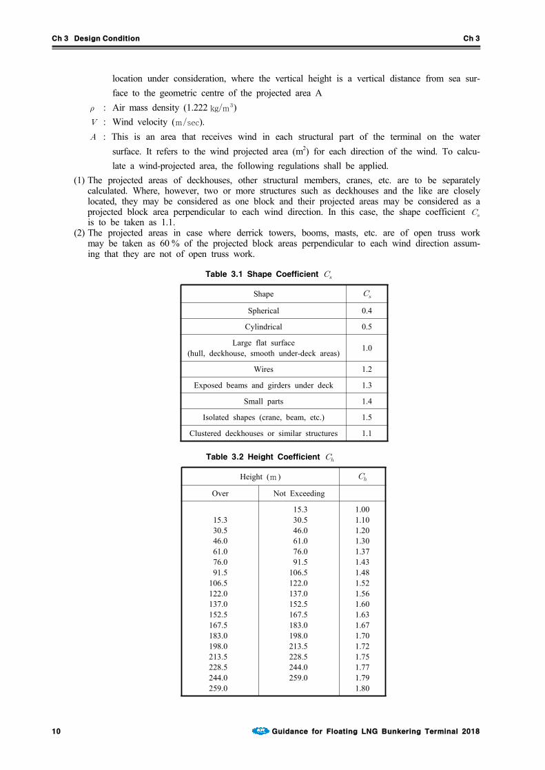
2. Wind load (F) shall be a value calculated using the formula below or higher for each part of the terminal. The load, however, can be calculated through a wind tunnel test that is recog-nized to be appropriate by Korean Register in relation to a terminal model.
: Wind load (N) : Shape coefficient given by Table 3.1 depending on the shape of structural members. : Height coefficient given by Table 3.2 depending on the vertical height in metres at the
Ch 3 Design Condition Ch 3
10 Guidance for Floating LNG Bunkering Terminal 2018
location under consideration, where the vertical height is a vertical distance from sea sur-face to the geometric centre of the projected area A
: Air mass density (1.222 kgm) : Wind velocity (msec). : This is an area that receives wind in each structural part of the terminal on the water
surface. It refers to the wind projected area (m2) for each direction of the wind. To calcu-late a wind-projected area, the following regulations shall be applied.
(1) The projected areas of deckhouses, other structural members, cranes, etc. are to be separately calculated. Where, however, two or more structures such as deckhouses and the like are closely located, they may be considered as one block and their projected areas may be considered as a projected block area perpendicular to each wind direction. In this case, the shape coefficient is to be taken as 1.1.
(2) The projected areas in case where derrick towers, booms, masts, etc. are of open truss work may be taken as 60 % of the projected block areas perpendicular to each wind direction assum-ing that they are not of open truss work.
Table 3.1 Shape Coefficient
Shape
Spherical 0.4
Cylindrical 0.5
Large flat surface(hull, deckhouse, smooth under-deck areas) 1.0
Wires 1.2
Exposed beams and girders under deck 1.3
Small parts 1.4
Isolated shapes (crane, beam, etc.) 1.5
Clustered deckhouses or similar structures 1.1
Table 3.2 Height Coefficient
Height (m )
Over Not Exceeding
15.330.546.061.076.091.5
106.5122.0137.0152.5167.5183.0198.0213.5228.5244.0259.0
15.330.546.061.076.091.5
106.5122.0137.0152.5167.5183.0198.0213.5228.5244.0259.0
1.001.101.201.301.371.431.481.521.561.601.631.671.701.721.751.771.791.80

Ch 3 Design Condition Ch 3
Guidance for Floating LNG Bunkering Terminal 2018 11
202. Wave loads
1. For the wave loads, which is used in global analysis, the corresponding provisions in Pt 3, Annex3-2 of Rules for the Classification of Steel Ships or a value is specified by the Owner under the approval of the Society.
2. In calculating wind loads, the following requirements are to be applied. (1) The wave loads are to be calculated, based on acceptable wave theories appropriate to the de-
sign depth of water at the operation area subject to the approval by the Society. The wave loads, however, may be determined from the tank test approved by the Society on a model of the unit.
(2) Waves from all directions are to be considered on the unit.(3) The wave loads produced by shipping water on the deck, the loads acting directly on the im-
mersed elements of the unit and the loads resulting from heeled positions or accelerations due to its motion are also to be considered.
(4) The vibration induced by waves is also to be considered.(5) In order to take into consideration a situation where a number of ships concurrently come
alongside the terminal for cargo handling, a floating multi-body interaction analysis is to be conducted.
203. Current loads
Consideration is to be given to the possible superposition of current and waves. In this case where this superposition is deemed necessary, the current velocity is to be added vectorially to the wave particle velocity and the resultant velocity is to be used to compute the total force.
204. Loads due to vortex shedding
The flutters of immersed structural members due to vortex shedding are also to be considered.
205. Deck loads
For deck loads, uniform and concentrated loads on the respective portions of the deck in each mode of operation and transit condition are to be taken into account. The values of the uniform loads, however, are not to be less than given in Table 3.3.Table 3.3 Deck Loads
Kind of deck Minimum load (kNm)
Helicopter deck 2
Accommodation spaces (including corridors and similar spaces) 4.5
Work areas and machinery spaces 9
Storage areas 13
206. Other loads
Other related loads shall be estimated by using methods recognized by Society.
Section 3 Corrosion Control Means and Corrosion Margins
301. General
Corrosion control means for units are to be provided in accordance with the relevant provisions specified in Pt 3 of the Rules and taking design service life, maintenance, corrosive environment, etc. into account.
302. Paint containing aluminium
Paint containing aluminium is not to be used in positions where cargo vapors may accumulate

Ch 3 Design Condition Ch 3
12 Guidance for Floating LNG Bunkering Terminal 2018
unless it has been shown by appropriate tests that the paint to be used does not increase theincendiary sparking hazard. Tests need not be performed for coatings with less than 10 percentaluminium by weight.
Section 4 Risk Assessment
401. Risk Assessment
In the initial stage of a terminal design, a risk assessment shall be conducted on the terminal or partial areas of the terminal that are subject to risk. The risk assessment shall include collision risk assessment, fire and explosion risk assessment, dropped object risk assessment and cryogenic leak-age risk assessment. It shall be conducted through application of validated analysis techniques and sufficiently so that scenarios for each terminal can be prepared to establish design criteria and also the reinforcement plans can be developed.
1. Collision Risk Assessment
(1) In developing a collision scenario, risk assessment in case of a collision of a gas carrier or bunkering ship to the side of the terminal during cargo loading and bunkering shall be primarily considered.
(2) In general, the integrity of hydrocarbon, low level of risk of cryogenic leakage and no loss of the stability of hull after collision shall be verified. In addition, the inertial load generated by a collision shall be considered in a cargo tank design.
2. Fire and Explosion Risk Assessment
(1) The structural load to cause a fire risk is determined by the temperature increase in the ex-posed components. For fire risk assessment, the impact of temperature changes in terms of time and space according to the intensity of the fire on all or parts of structural members is analyzed.
(2) Explosion load is affected by time and space-related pressure distribution. The most important time variables are the time of pressure increase and the duration of maximum pressure and pulsation. In general, it is assumed that the explosion pressure in components and lower struc-ture is uniformly distributed. However, the overall spatial distribution, pressure and duration are not uniform.
3. Dropped Object Risk Assessment
(1) The load of a dropped object is determined by kinetic energy, which is controlled by the mass of the object, and instantaneous energy, which is controlled by speed in addition to the mass.
(2) Kinetic energy generated by a dropped object strains the structure or parts of the affected area. In general, it accompanies serious structural damage of the components as a result of significant plastic deformation.
4. Cryogenic Leakage Risk Assessment
(1) Cryogenic LNG leakage can occur from the re-liquefaction system, and the deck shall be pro-tected from risk.
(2) Spray shields to protect humans, the deck and cargo tank shall be installed for high-pressure liquid lines at the back of the boost-up pump.

Ch 4 Materials and Welding Ch 4
Guidance for Floating LNG Bunkering Terminal 2018 13
CHAPTER 4 MATERIALS AND WELDING
Section 1 General
101. Application
1. The materials used for important structural members are to be in accordance with Pt 2, Ch 1 of Rules for the Classification of Steel Ships.
2. The welding work of important structural members is to be in accordance with Pt 2, Ch 2 of Rules for the Classification of Steel Ships.
3. Underdeck and hull interface plating or bracket structures attached to the deck or hull should have the same or compatible material grade as the deck or hull structure, respectively.
4. Mooring system chains, chain parts, wire ropes, fiber ropes, and anchors as well as the windows provided for accommodation spaces are to be in accordance with Pt 4 of Rules for theClassification of Steel Ships or standards deemed appropriate by the Society.
5. For the materials of components that are in contact with gas as well as gas tanks, gas pipeline and pressure vessels, the provisions in Pt 7, Ch 5, Sec. 6 of Rules for the Classification of SteelShips is to be applied. In particular, the materials for LNG pipeline system is to be complied with Pt 7, Ch 5, 602. of Rules for the Classification of Steel Ships. However, the require-ments may be alleviated appropriately for materials used in ventilation pipes in openings where the gas temperature under atmospheric pressure is –55°C or higher through which the gas is not dis-charged in a liquid state. The materials with a melting point below 925°C shall not be used in pipelines outside the gas tank with the exception of a case where heat is radiated at the A-60 level through a short pipe attached to the gas tank. In principle, the materials shall meet the certified standards.

Ch 5 Hull Construction and Equipment Ch 5
Guidance for Floating LNG Bunkering Terminal 2018 15
CHAPTER 5 HULL CONSTRUCTION AND EQUIPMENT
Section 1 General
101. General
1. The design and construction of the hull, superstructure and deckhouses for units that are new builds or conversions are to be based on the applicable requirements of design considerations of this guide and not specified in this guide are to be in accordance with the Rules.
2. Design Considerations of this Guide reflects the different structural performance and demands ex-pected for an installation transiting and being positioned at a particular site on a long-term basis compared to that of a vessel engaged in unrestricted seagoing service.
102. Load line
1. A mark designating the maximum allowable draught for loading is to be located in easily visible positions on units as deemed appropriate by the Society or in positions easily distinguishable by the person in charge of liquid transfer operations.
2. The designation of load lines is to comply with the requirements given in the “International Convention on Load Lines, 1996 and Protocol of 1988 relating to the International Convention on Load Lines, 1966”, unless specified otherwise by the relevant flag states or coastal states.
103. Loading manual, intact stability information and instruction for operation
1. For the case of units, loading manual and loading instruments are to be installed are to be as specified in Pt 3, Ch 3, Table 3.3.3 of Guidance for the Classification of Steel Ships and Rules for the Classification of Steel Barges.
2. In order to avoid the occurrence of unacceptable stress in unit structures corresponding to all cargo and ballast loading conditions and topside modules arrangement and mass and to enable the master or the person-in-charge of loading operations to adjust the loading of cargo and ballast, units are to be provided with loading manuals approved by the Society. Such loading manuals are to at least include the following (1) to (4) items as well as relevant provisions given in Pt 3, Ch 3 of Rulesfor the Classification of Steel Ships.(1) The loading conditions on which the design of a unit has been based, including the permissible
limits of longitudinal still water bending moments and still water shearing forces.(2) The calculation results of longitudinal still water bending moments and still water shearing
forces corresponding to the loading conditions.3. In addition to Par 2 above, a loading computer that is capable of readily computing longitudinal
still water bending moments and still water shearing forces working on units corresponding to all oil and ballast loading conditions and the operation manual for such a computer is to be provided on board.
4. The capability of the loading computer specified in Par 3 above to function as specified in the lo-cation where it is installed is to be confirmed.
5. A intact stability information booklet approved by the Society is to be provided on board in ac-cordance with Pt 1, Annex 1-2 of Rules for the Classification of Steel Ships. This booklet is to include the results of stability evaluations in representative operating conditions.
6. Instructions for the loading and unloading, and transfer and offloading operations of cargo and bal-last are to be provided on board. In cases where mooring systems can be isolated, the procedures for isolating and re-mooring are also to be included.
7. The loading precautions such as maximum cargo loading weight on the deck and equipment loading weight in the operating condition, etc., is to be stated in appropriate documents such as loading manual or stability information.

Ch 5 Hull Construction and Equipment Ch 5
16 Guidance for Floating LNG Bunkering Terminal 2018
Section 2 Survival Capability and Location of Cargo Tanks
201. General
1. Damage stability criteria are to be in accordance with the requirements specified in Pt 7, Ch 5,Sec 2 of Rules for the Classification of Steel Ships. under the environmental conditions speci-fied in Ch 3.
2. The arrangements of watertight compartments, watertight bulkheads and closing devices are to be in accordance with the requirements specified in Rules for the Classification of Steel Ships and Rules for the Classification of Steel Barges.
3. The requirements may be applied appropriately mitigated by the requirements of damage criteria for 2PG or 3G ship.
4. Damage stability criteria is to be applied to the damage assumptions in Pt 7, Ch 5, Sec 2 ofRules for the Classification of Steel Ships, except for bottom damage.
Section 3 Longitudinal Strength
301. Longitudinal hull girder strength
1. For the longitudinal strength of a terminal, the bending strength, shear strength and buckling strength are to be based on Pt 3 of the Rules basically. However, for barge type unit of 150 m or less, it is to be in accordance with the Rules for the Classification of Steel Barges. The to-tal hull girder bending moment, is the sum of the maximum still water bending moment for operation on site or in transit combined with the corresponding wave-induced bending moment () expected on-site and during transit to the installation site.
2. In lieu of directly calculated wave-induced hull girder vertical bending moments and shear forces, recourse can be made to the use of the Environmental Severity Factor (ESF) approach described of this guide. The ESF approach can be applied to modify the Steel Vessel Rules wave-induced hull girder bending moment and shear force formulas. Depending on the value of the Environmental Severity Factor, , for vertical wave-induced hull girder bending moment (see this Guide), the minimum hull girder section modulus, min of unit may vary in accordance with the following.
3. Environmental Severity Factor
Environmental Severity Factors are adjustment factors for the dynamic components of loads and the expected fatigue damage that account for site-specific conditions as compared to North Atlantic un-restricted service conditions. (1) ESFs of the Beta () Type
This type of ESF is used to introduce a comparison of the severity between the intended envi-ronment and a base environment, which is the North Atlantic unrestricted service environment. In the modified formulations, the factors apply only to the dynamic portions of the load com-ponents, and the load components that are considered “static” are not affected by the in-troduction of the factors.
min
< 0.7 0.85min
0.7 < < 1.0 Varies linearly between 0.85min and min
> 1.0 min
Where min = minimum hull girder section modulus as required in Pt 3,Ch 3, 203. of Rules forthe Classification of Steel Ships
Table 5.1 Minimum hull girder section modulus

Ch 5 Hull Construction and Equipment Ch 5
Guidance for Floating LNG Bunkering Terminal 2018 17
where
: most probable extreme value based on the intended site (100 years return period),transit (10 years return period), and repair/inspection (1 year return period)
: most probable extreme value base on the North Atlantic environment
A of 1.0 corresponds to the unrestricted service condition of a seagoing vessel. A value of less than 1.0 indicates a less severe environment than the unrestricted case.
(2) ESFs of the Alpha () Type This type of ESF compares the fatigue damage between the specified environment and a base environment, which is the North Atlantic environment. This type of ESF is used to adjust the expected fatigue damage induced from the dynamic components due to environmental loadings at the installation’s site. It can be used to assess the fatigue damage accumulated during the histor-ical service either as a trading vessel or as a unit, including both the historical site(s) and his-torical transit routes.
where : annual fatigue damage based on the North Atlantic environment (unrestricted service)
at the details of the hull structure : annual fatigue damage based on a specified environment, for historical routes, histor
ical sites, transit and intended site, at the details of the hull structure
Section 4 Structural Design and Analysis of the Hull
401. Structural design of the hull
1. Regarding the design of hull structures, the respective requirements in Pt 3 of Rules for theClassification of Steel Ships are to be applied with consideration to Sec 1 and Sec 2 of Ch 3 of this Guidance. In this Guideline, the characteristics of a floating LNG bunkering terminal that moors for a long period of time on specific waters need to be considered.
2. When approval has been given by Society, the measurements of hull structural members can be decided according to direct strength calculation. If the measurements obtained through direct strength calculation are larger than those specified in Pt 3 of Rules for the Classification ofSteel Ships, the measurements is to be decided as the calculated results.
3. For direct strength calculation according to the provisions in paragraph 1 above, data necessary in the calculation and the result shall be submitted to Society.
402. Direct strength calculation
1. Direct strength calculation is divided into cargo hold structural analysis and frontal structural analysis. For the cargo hold structural analysis, the related requirements in Paragraph 7, Annex 3-2III, Pt 3 of Rules for the Classification of Steel Ships is to be applied and, for the frontal structural analysis, the requirements in Annex 3-2 II, Part 3 of Rules for the Classification ofSteel Ships is to be applied.
2. To decide the measurements of hull structural members through cargo hold structural analysis, the scope and procedures can be agreed on through consultation with Korean Register.
In case the size of cargo hold model division by factor does not sufficiently show the areas sub-ject to high stress, the areas shall be reviewed through division with detailed factors.
3. As for the wave load applied to frontal structural analysis, a probability value equivalent to the
Ch 5 Hull Construction and Equipment Ch 5
18 Guidance for Floating LNG Bunkering Terminal 2018
100-year reproduction cycle for terminal operating waters shall be used.
4. In case mooring system is included in frontal structural analysis, the weight and dynamic load of mooring line shall be considered. The dynamic load of mooring line shall be compared with the result of mooring analysis in order to check that it is conservatively reflected in the frontal struc-tural analysis.
5. The results of direct strength calculation shall not be used for the purpose of reducing the meas-urements of structural members.
403. Fatigue analysis
1. The fatigue strength analysis target members shall be decided considering the style of hull structure and criticality of structural members. As for the target members, those subject to the problems of water tightness in compartments as a result of cracking or those subject to the probability of fa-tigue cracking as a result of the concentration of stress due to geometric discontinuation of the structure shall be extensively selected.
2. For terminal fatigue analysis, temporary fatigue analysis, cargo hold fatigue analysis and frontal fa-tigue analysis shall be conducted according to Annex 3-3, Pt 3 of Rules for the Classificationof Steel Ships. However, if deemed appropriate by Society, fatigue strength can be examined us-ing other methods.
404. Cargo Containment system
For design and analysis of cargo containment system, the regulations in Pt 7, Ch 5, Sec 4 of Rules for the Classification of Steel Ships shall be adhered to.
405. Sloshing load evaluation/cargo containment system strength evaluation
For the evaluation of sloshing load generated in the cargo hold and structural safety of carbon con-tainment system, the respective requirements in Guidance for Assessment of Sloshing Loadand Structural Strength of Cargo Containment System can be applied.
406. Position mooring/hull interface structural analysis
For the terminal, yield strength, buckling strength and fatigue strength of the hull and positioning system interface structures shall be examined through finite element analysis. For yield and buckling strength analysis, the provisions in Annex 3-2 III, Paragraph 7, Pt 3 of Rules for theClassification of Steel Ships can be applied. For fatigue strength, those specified in Annex 3-3,Pt 3 of Rules for the Classification of Steel Ships can be adhered to. However, if deemed ap-propriate by Society, interface structure strength can be reviewed using other methods.
1. Turret or SPM type mooring system, external to the terminal’s hull
(1) Fore end mooring The minimum extent of the model is from the fore end of the installation, including the turret
structure and its attachment to the hull, to a transverse plane after the aft end of the foremost cargo tank in the installation. The model can be considered fixed at the aft end of the model.
(2) Aft end mooring The minimum extent of the model is from the aft end of the installation and including the tur-
ret structure and its attachment to the hull structure to a transverse plane forward of the fore end of the aft most cargo tank in the hull. The model can be considered fixed at the fore end of the model.
2. Mooring system internal to the Installation Hull (Turret Moored)
(1) Fore end Turret The minimum extent of the FEM model is from the aft end of the installation and including
the turret structure, its attachment to the hull structure to a transverse plane forward of the fore end of the aft most cargo tank in the hull. The model can be considered fixed at the fore end of the model.
(2) Midship Turret The range of FEM model is from the transverse bulkhead at the back end of rear cargo hold
that is located near the cargo head including turret to the transverse bulkhead at the front end

Ch 5 Hull Construction and Equipment Ch 5
Guidance for Floating LNG Bunkering Terminal 2018 19
of the first cargo hold. (3) Load State As the load conditions, the two load states below, which exert the worst impact on hull struc-
tures, shall be included. (A) Load state where a full-load tank located close to the cargo hold including a turret is ap-
plied with maximum internal pressure and another empty tank is applied with minimum ex-ternal pressure (Refer to Fig 5.1)
(B) Load state where an empty tank located close to the cargo hold including a turret and of another full-load tank are applied with maximum external pressure (Refer to Fig. 5.2)
3. Spread moored installations
The local foundation structure and installation structure are to be checked for the given mooring loads and hull structure loads, where applicable, using an appropriate FEM analysis.
407. Other Applications
For other matters concerning hull structure design and analysis is to be in accordance with the re-quirements specified in Guidance for Floating Production Units.
Section 5 Hull Arrangements
501. Application
The applicable requirements for hull arrangements is to be in accordance with Pt 7, Ch 5, Sec 3 of the Rules. However, the requirements in Pt 7, Ch 5, 301. 1 (2) of the Rules may not be applied.
Section 6 Hull Equipment
601. Mooring systems for temporary mooring
1. The mooring systems for temporary mooring specified in Rules for Classification of MobileOffshore Drilling Units need not be fitted. In cases where the Society deems such necessary in consideration of the form of unit operations, the mooring systems for temporary mooring specified in Rules for Classification of Mobile Offshore Drilling Units are required.
2. In the case of single-point mooring systems to moor receiving vessels, the chafing chain used ends for mooring lines are to be fitted and are to comply with the following:
Fig 5.1 Loading Pattern with 2/3 Scanting Draft
Fig 5.2 Loading Pattern with Scanting Draft

Ch 5 Hull Construction and Equipment Ch 5
20 Guidance for Floating LNG Bunkering Terminal 2018
(1) The chafing chain is to be the offshore chain specified in Pt 4 of Rules for theClassification of Steel Ships, and the chain standard is short lengths (approximately 8 m ) of 76 mm diameter.
(2) The arrangement of the end connections of chafing chains is to comply with any standards deemed appropriate by the Society.
(3) Documented evidence of satisfactory tests of similar diameter mooring chains in the prior six month period may be used in lieu of breaking tests subject to agreement with the Society.
3. Equipment used in mooring systems to moor at jetty etc. in order to install plant or mooring equipment for the mooring support ships and shuttle tankers, except for the equipment specified in Par 2 above, is to be as deemed appropriate by the Society.
602. Guardrails
1. The guardrails or bulwarks specified in Pt 4 of Rules for the Classification of Steel Ships are to be provided on weather decks. In cases where guardrails will become hindrances to the tak-ing-off and landing of helicopters, means to prevent falling such as wire nets, etc. are to be provided.
2. Freeing arrangements, cargo ports and other similar openings, side scuttles, rectangular windows, ventilators and gangways are to be in accordance with the requirements specified in Rules for theClassification of Steel Ships and Rules for the Classification of Steel Barges, unless speci-fied otherwise by the relevant flag states or coastal states.
3. Ladders, steps, etc. are to be provided inside compartments for safety examinations as deemed ap-propriate by the Society.
603. Fenders
1. Suitable fenders fore contact with the gunwales of other ships such as support ships, tug boats, shuttle tankers, etc. are to be provided.
2. The most common fender used for side-by-side transfer operations is the high pressure pneumatic type. These fenders are generally favoured for their robustness and longevity. The low pressure pneumatic type have been found useful for emergency situations where ease of transport is a first priority. However, they can have the disadvantage of much shorter life in service. Foam filled fend-ers are not commonly used but owing to lighter construction they can have advantages when used as secondary fenders.
3. Fender size will also be dictated by the freeboard of the ships, and the diameter of each floating fender should be no more than half the minimum freeboard of the smaller ship.
4. Fenders used in side-by-side transfer operations offshore are divided into two categories:(1) Primary fenders which are positioned along the parallel body of the ship to afford the max-
imum possible protection during mooring and unmooring.(2) Secondary fenders which may be used to protect bow and stern plating from inadvertent contact
during mooring and unmooring. 5. For the details, Ship to Ship Transfer Guide(Liquefied Gases) issued by OCIMF is to be referred.

Ch 6 Positioning Systems Ch 6
Guidance for Floating LNG Bunkering Terminal 2018 21
CHAPTER 6 POSITIONING SYSTEMS
Section 1 General
101. General
1. Terminals are to be provided with positioning systems complying with the requirements given in this Chapter.
2. The positioning system is to be designed and arranged taking into account the connection with the receiving vessel.
102. Mooring systems
1. Mooring systems are to be sufficiently capable of positioning Units at a specific location against all of the design conditions for positioning as well as all of the safety conditions for systems em-bedded on the seabed and the ships laden with offloaded LNG from such Terminals.
2. In the case of mooring systems of Units operated in sea areas where low temperature, freezing, ice formation, etc. are predicted, the effects of such things are to be taken into consideration or appro-priate countermeasures are to be provided.
103. Conditions to be considered for mooring system analysis
1. The various conditions of a Floating Installation which are important for the designer to consider are as follows. (1) Intact Design A condition with all components of the system intact and exposed to an environment as de-
scribed by the design environmental condition (DEC). (2) Damaged Case with One Broken Mooring Line
(A) A condition with any one mooring line broken at the design environmental condition (DEC) that would cause maximum mooring line load for the system. The mooring line subjected to the maximum load in intact extreme conditions when broken might not lead to the worst broken mooring line case. The designer should determine the worst case by analyzing sev-eral cases of broken mooring line, including lead line broken and adjacent line broken cases.
(B) For a disconnectable mooring system with quick release system, the mooring analysis for a broken line case may not be required.
(C) For unusual (non-symmetric) mooring pattern, mooring analysis for the broken line case for the disconnectable environmental condition may be required.
(D) For a system utilizing the SALM concept, the case with one broken mooring line is not relevant. A case considering loss of buoyancy due to damage of a compartment of the SALM structure should be analyzed for position mooring capability.
(E) The loss of thruster power or mechanical failure on thruster-assisted position mooring sys-tems will be considered on a case-by-case basis.
(3) Transient Condition with One Broken Mooring Line A condition with one mooring line broken (usually the lead line) in which the moored in-
stallation exhibits transient motions (overshooting) before it settles at a new equilibrium position. 2. The proper clearances between Units and any near-by structures and ships are to also be verified.
3. In the case of SALM, cases considering a loss of buoyancy due to damage of a compartment of the SALM structure should be analyzed for position mooring capability instead of cases with one broken mooring line.
4. Mooring system analysis in combination with the assistance of propulsion systems, thrusters, etc. is to be as deemed appropriate by the Society.

Ch 6 Positioning Systems Ch 6
22 Guidance for Floating LNG Bunkering Terminal 2018
Section 2 Mooring Analysis
201. General
1. Mooring analysis is to be conducted based on the environmental conditions as specified in Ch 3,Sec 1 & 2. Such analysis is to include the evaluations of the mean environmental forces, the ex-treme response of the Units, and the corresponding mooring line tension.
2. Mooring system analysis as deemed appropriate by the Society is to be carried out for the all pro-spective mooring conditions. The effects due to the draught changes of the Units are to be taken into consideration. In the case of Units mooring to individual periphery facilities, such as CALM, separate from the Units, mooring analysis for the total system, including any periphery facilities, is to be carried out.
3. In case of mooring systems using mooring lines, analysis is to be carried out under the awareness that there is no harmful excessive bend of any lines in way of the contact points between mooring lines and mooring equipment (fairleaders, etc.) fitted on board Units.
4. The mooring systems of Units and the seabed mooring points (anchors, sinkers, piles, etc.) of any periphery facilities for positioning are not to be slid, uplifted, overturned, etc. against any envi-sioned force from the mooring lines. In cases where scouring effects are not considered to be neg-ligible, appropriate consideration is to be taken such as the modification of burial depth, protection against the flow around seabed mooring points, etc.
5. Mooring analysis is to be made under the awareness that the equipment for mooring systems is subjected to steady forces of wind, current and mean wave drift force as well as wind and wave induced dynamic forces. Maximum line tension is to be calculated considering that wind, wave, and current come from unrestricted directions. However, in cases where the data for the specific positioning area of a Units prove a restricted direction of wind, wave and current in that area, cal-culations under such specific directions may be accepted in cases where deemed appropriate by the Society.
6. The combination of external forces for mooring analysis under single point mooring system (for ex-ample, turret mooring) shall be decided based on the state of the sea in a specific operational area. In case useful data on the direction of the wind, waves and tides in the operation area are not available, the following combinations shall be considered at the least in relation to wind, waves and tides of different directions:(1) Wind and tide in the same direction, angle to wave 30°;(2) Angle of wind to wave 30°, angle of tide to wave 90°;(3) Angle of wind to wave 90°, angle of tide to wave 30°; (4) Angle of wind to wave 30°, angle of tide to wave 45°; (5) Angle of wind to wave 45°, angle of tide to wave 30°;
7. The sea condition where a local and rapid change (squall) is expected shall also be considered as an environmental condition. The investigation shall be conducted by considering that squall is ap-proaching from any direction and that external forces (for example, wind or waves) are instantly changing. In case a course angle adjusting system (for example, a thruster that is effective while the sea condition is rapidly changing) is installed, an investigation on rapid changes of the sea con-dition can be omitted.
8. The maximum offset of the terminal and maximum tension of mooring line shall be calculated. According to the purpose of analysis, quasi-static or dynamic analysis method deemed to be appro-priate by Korean Register (for example, API RP 2SK recommendations for design and analysis of floating structure positioning system) can be used.
9. As an analysis method, time history response analysis or frequency response analysis shall be used. However, the maximum offset of the terminal and maximum tension of mooring line shall be cal-culated through time history response analysis or a model test in relation to the single point moor-ing system (for example, turret mooring system).

Ch 6 Positioning Systems Ch 6
Guidance for Floating LNG Bunkering Terminal 2018 23
202. Mean environmental forces, etc.
1. The calculation of steady forces due to wind and current are to be in accordance with Ch 3, Sec2.
2. Mean and oscillatory low frequency drift forces may be determined by model tests or using hydro-dynamic computer programs verified against model test results or other data. Mean drift forces to be as deemed appropriate by the Society.
3. Load information is to be prepared based on appropriate analysis, model tests, etc., and such in-formation is to be provided on board.
203. Maximum offset and yaw angle of the installation
1. Maximum offset may be calculated as the sum of the offset due to steady components such as wind, current, and wave (steady drift), and dynamic motion offset due to the dynamic components of forces induced by waves (high and low frequency).
2. The following formula is to be adopted as the standard for calculating maximum offset. In the fol-lowing formula, mean offset and significant single amplitude or maximum amplitude of the max-imum offset obtained from model tests or analysis methods deemed appropriate by the Society are used.
m ax m ax
orm ax m ax
whichever is greater.
where : Mean offset of the Units due to wind, current and mean drift : Significant single amplitude low frequency motion : Significant single amplitude wave frequency motion
3. The maximum values of low frequency motion m ax and wave frequency motion m ax may be calculated by multiplying their corresponding significant single amplitude values by the factor ,which is to be calculated as follows:
∈
: Hypothetical storm duration (seconds), minimum 10,800 (i.e. 3 hours). In the case of areas with longer storm durations (monsoon areas), needs to be a higher value.
: Average response zero up-crossing period (seconds)
4. In the case of low frequency components, may be taken as the natural period of a Units with a mooring system. can be calculated as follows using the mass of the Units (including added mass, etc.) and the stiffness of the mooring system for horizontal motion (port-starboard, fwd-aft, yaw motion) at the Units s mean position and equilibrium heading as follows:
In such cases, information about the stiffness of mooring systems, damping forces, and other pa-

Ch 6 Positioning Systems Ch 6
24 Guidance for Floating LNG Bunkering Terminal 2018
rameters which may affect the maximum values of low frequency motion are to be submitted to the Society for reference.
5. In order to assess the motion of Units in waves in relatively shallow water, shallow water effects are to be taken into account. In cases where the changes in tidal levels in shallow waters are rela-tively large, the tidal difference affecting Units motion and the tension acting on mooring lines is to be considered.
6. In the case of single point mooring systems, the maximum offset for motion in waves is to be calculated using a non-linear time history domain method or model tests. In such cases, wave ir-regularities and wind variances are to be considered as well.
204. Calculation of mooring line tensions, etc.
1. In order to calculate the maximum tension acting on the mooring lines, the severest combination of wind, waves and current is to be considered together with a sufficient number of angles of incidence. Although this severest condition generally corresponds to cases where all of the wind, wave and current directions are consistent, in the case of specific sea areas, the combination of wind, waves and current in different directions which are likely to create a higher tension are to be taken into account as needed.
2. In calculating the tension acting on mooring lines, at least Sub-paragraph (1) to (3) mentioned be-low are to be considered. Sub-paragraph (4) may be assessed as necessary. This analytical proce-dure can be called a quasi-static analytical procedure and is to be adopted as the standard for cal-culating the tensions acting on mooring lines. The maximum tension of mooring lines calculated by this quasi-static analytical procedure has to have, in principle, a suitable safety factor specified in Table 6.1 corresponding to specific breaking tension.(1) Static tension of mooring lines due to net weight and buoyancy.(2) Steady tension of mooring lines due to a steady horizontal offset of Units induced by wind,
waves and current.(3) Quasi-static varying tension of mooring lines due to Units motion induced by waves.(4) Tension of mooring lines in consideration of their elastic elongation in cases where they are
used in a moderately taut condition (generally in shallow waters), or in cases where mooring lines with low rigidity such as fibre ropes are used.
Table 6.1 Safety Factors for Mooring Lines
ConditionSafety Factor
Chains or wire ropes Synthenic fibre ropes
Intact
Dynamic analysis 1.67 2.50
Quasi-static analysis 2.00 3.00
One broken mooring line (at new equilibrium position)
Dynamic analysis 1.25 1.88
Quasi-static analysis 1.43 2.15
One broken mooring line (transient condition)
Dynamic analysis 1.05 1.58
Quasi-static analysis 1.58 1.77
3. The maximum tension in a mooring line m ax is to be determined as follows:m ax m ax
or

Ch 6 Positioning Systems Ch 6
Guidance for Floating LNG Bunkering Terminal 2018 25
m ax m ax
whichever is greater
where
: Mean mooring line tension due to wind, current and mean steady drift : Significant single amplitude low frequency tension : Significant single amplitude wave frequency tension
The maximum values of low frequency tension m ax and wave frequency tension m ax are to be calculated by the same procedure as that used for obtaining the motions at low frequency and wave frequency described in 203. 2 above.
4. In case time history response analysis is used, the mooring line tension shall be calculated accord-ing to (1) or (2) below in relation to the single combination of loads.(1) This is a method to conduct the calculation, which takes at least three hours, 20 times or more
by changing the random number seed of irregular load. The values of maximum tension ob-tained from each calculation are averaged. However, the number of calculations can be reduced on the basis of the results of a study about the impact exerted on the analysis result of low-frequency motion of mooring system as well as wave frequency and low-frequency motion properties and on the analysis result of variables, such as nonlinear elements of the region.
(2) The statistically expected maximum tension is calculated based on the required time of at least three hours.
5. In the analysis of the one broken mooring line condition given in Par 4 above, in the case of a Units which is moored in the proximity of other Units, the safety factors for any mooring lines ar-ranged on the opposite side of the other Units are to be taken as 1.5 times of those indicated in Table 6.1.
6. In cases where the following Sub-paragraph (1) and (2) are taken into account in addition to Par2 above, the safety factors required in cases where quasi-static analytical procedures are adopted may be modified to values deemed appropriate by the Society.(1) Dynamic tension in mooring lines due to damping forces and inertia forces acting on each
mooring line in cases where they are generally used in deep water.(2) Quasi-static low-frequency varying tension of mooring lines due to the low-frequency motion of
Units in irregular waves in cases where they are used in a sufficiently slack condition. (in cas-es where the natural period of motion of a Units in a horizontal plane is sufficiently longer than the period of ordinary waves)
7. In the case of Taut Mooring systems, the following are to be complied with in addition to Par 1 to Par 6 above:(1) Such systems are to be designed so that no slack is caused in any mooring line due to
changes in line tension.(2) Changes in the tension of mooring lines due to tidal difference including astronomic tides and
meteorological tides are to be considered.(3) The effects of any changes in the weight and displacements of heavy items carried on board
upon the tension of mooring lines are to be sufficiently taken into account.(4) In cases where the effects of the non-linear behavior of mooring lines on their tension are not
negligible, tension due to non-linear behavior is to be considered.
205. Fatigue analysis
1. The fatigue life of mooring lines is to be assessed in consideration of the changing tension range, and the number of cycles, . The fatigue life of mooring lines is to be evaluated by estimating the fatigue damage ratio, in accordance with Miner's law using a curve relating the changing tension range to the number of cycles to failure.

Ch 6 Positioning Systems Ch 6
26 Guidance for Floating LNG Bunkering Terminal 2018
: Number of cycles within the tension range interval, , for a given sea state. : Number of cycles to failure at changing tension range, .
The cumulative fatigue damage, for all expected number of sea states (identified in a wave scatter diagram) is to be calculated as follows:
The value of divided by the usage factor (ɳ) specified in Table 6.2 is not to be greater than 1. In such cases, the usage factors for the underwater parts of the mooring lines are, in principle, to be taken to be that of an inaccessible and critical area.
2. The fatigue life of each mooring line component is to be considered. curves for various line components are to be based on fatigue test data and regression analysis.
3. Special consideration is to be given to the fatigue strength of the connections between the mooring lines and hull structures of Units, the connections between the mooring lines and seabed mooring points, and the connections between the mooring lines and other mooring lines.
Table 6.2 Usage Factor, ɳCriticality of the structural members Accessibility Usage Factor, ɳ
Normal High 1.0
Normal Low 0.5
High High 0.33
High Low 0.1*1
(NOTES)1. For the structural members whose criticality is high and accessibility is low, special designconsideration is to be taken into account in order to provided appropriate measures for inspection andconsideration monitoring in principle.
Section 3 Design of Mooring Lines, etc.
301. Components of mooring lines and seabed mooring points
1. Each component of mooring systems is to be designed using design methods by which the severest loading condition can be verified. The strength of connecting shackles, links, etc. used at the con-necting points between the mooring lines and hull structures of Units and between mooring lines and seabed mooring points are, in principle, to have safety factors against the breaking loads of such mooring lines or the ultimate strength of structures not less than those indicated in the Table6.3.
Safety factor
Intact condition (unmoored Units in storm conditions) 2.50
Intact condition (moored Units under operating conditions) 3.00*1
(NOTES)1. In cases where a safety factor of 2.0 is ensured, even in the any one bro-
ken mooring line condition, a safety factor of 2.5 may be accepted.
Table 6.3 Safety Factor
Ch 6 Positioning Systems Ch 6
Guidance for Floating LNG Bunkering Terminal 2018 27
2. In the case of catenary mooring systems, mooring lines are to be sufficiently long so that no up-lifting forces act on the parts of the mooring line around the mooring point on the seabed un-der design conditions. In the case of soft clay conditions (like in the Gulf of Mexico), a small an-gle for the one broken mooring line condition may be considered in cases where deemed accept-able by the Society.
3. Information verifying that the holding power of seabed mooring points is sufficient against the ex-pected tension from the mooring lines in accordance with 204. is to be submitted to the Society for reference.
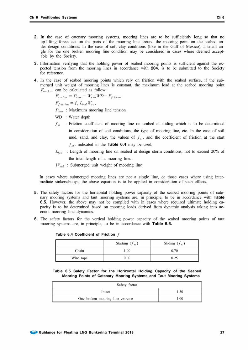
4. In the case of seabed mooring points which rely on friction with the seabed surface, if the sub-merged unit weight of mooring lines is constant, the maximum load at the seabed mooring point can be calculated as follow:
: Maximum mooring line tensionWD : Water depth : Friction coefficient of mooring line on seabed at sliding which is to be determined
in consideration of soil conditions, the type of mooring line, etc. In the case of soft mud, sand, and clay, the values of , and the coefficient of friction at the start , indicated in the Table 6.4 may be used.
: Length of mooring line on seabed at design storm conditions, not to exceed 20% of the total length of a mooring line.
: Submerged unit weight of mooring line
In cases where submerged mooring lines are not a single line, or those cases where using inter-mediate sinkers/buoys, the above equation is to be applied in consideration of such effects.
5. The safety factors for the horizontal holding power capacity of the seabed mooring points of cate-nary mooring systems and taut mooring systems are, in principle, to be in accordance with Table6.5. However, the above may not be complied with in cases where required ultimate holding ca-pacity is to be determined based on mooring loads derived from dynamic analysis taking into ac-count mooring line dynamics.
6. The safety factors for the vertical holding power capacity of the seabed mooring points of taut mooring systems are, in principle, to be in accordance with Table 6.6.
Starting ( ) Sliding ()
Chain 1.00 0.70
Wire rope 0.60 0.25
Table 6.4 Coefficient of Friction
Safety factor
Intact 1.50
One broken mooring line extreme 1.00
Table 6.5 Safety Factor for the Horizontal Holding Capacity of the Seabed
Mooring Points of Catenary Mooring Systems and Taut Mooring Systems

Ch 6 Positioning Systems Ch 6
28 Guidance for Floating LNG Bunkering Terminal 2018
Safety factor
Intact 1.20
One broken mooring line extreme 1.00
Table 6.6 Safety Factor for the Vertical Holding Capacity of the Seabed
Mooring Points of Taut Mooring Systems
Section 4 Mooring Equipment
401. General
1. The equipment of positioning systems is to have sufficient redundancy. In cases where any single unit of equipment of positioning systems is fitted on board Units, special consideration is to be given to the reliability of such equipment and its components. In cases where the failure of any single unit of equipment may lead to loss of positioning capability, an additional set of such equipment will be required as deemed necessary by the Society.
2. Means are to be provided whereby the normal operations of positioning systems can be sustained or restored even though one unit of equipment becomes inoperative. In the case of driving units, special consideration is to be given for preventing loss of function.
3. The prime movers used for positioning systems are to be designed to operate under the static con-ditions as well as under the dynamic conditions given below. Deviation from given values may be permitted, taking into consideration the type, size and service conditions, etc. of the Units in cases where deemed appropriate by the Society.(1) In the case of ship type and barge-type Units: Rolling up to 22.5° and simultaneously pitching up to 7.5°(2) In the case of column-stabilized Units: Dynamic inclination up to 22.5° in any direction
402. Chains, wire ropes, etc.
1. Chains, wire ropes or fibre ropes used for mooring systems are to comply with the requirements given in Pt 4, Ch 8, Sec 4 and Sec 5 of Rules for the Classification of Steel Ships or any standards deemed appropriate by the Society. In cases where the Grade R4 chains specified in Pt4, Ch 8 of Rules for the Classification of Steel Ships or stronger chains are used, special care is to be taken because repairs by welding for any defects, loose studs and corrosion by weld-ing is, in principle, prohibited for such chains.
2. Intermediate sinkers, intermediate buoys and anchors, sinkers, piles, etc. for seabed mooring points are to be as deemed appropriate by the Society.
403. Chain stoppers or windlasses, winches, etc.
1. Individual equipment of mooring systems is, in principle, to be approved by the Society.
2. Chain stoppers used for mooring systems are to have sufficient strength against the breaking strength of the mooring line as deemed appropriate by the Society. The prototypes of chain stop-pers are to be verified to have sufficient strength against the breaking strength of the mooring line. It is to be verified that the stress calculated by structural analysis under the awareness that the mooring line is subjected to design maximum loads does not exceed the specified proof stress of the chain stoppers.
3. Windlasses used for the catenary mooring systems of Units are to comply with the requirements specified in following Sub-paragraph (1) to (3):(1) Each windlass is to be provided with two independent power-operated brakes. Each brake is to
be capable of holding against a static load of at least 50% of braking strength of mooring lines. In cases where deemed appropriate by the Society, one of the brakes may be replaced by a manually operated brake.

Ch 6 Positioning Systems Ch 6
Guidance for Floating LNG Bunkering Terminal 2018 29
(2) Windlasses are to have sufficient dynamic braking capacity to control the normal combination of loads from anchors, mooring lines and anchor handling vessels during the deployment of an-chors at the maximum design pay-out speed of the windlass.
(3) In cases where a power source for a windlass is lost, power-operated braking systems are to be automatically applied and be capable of holding against 50% of the total static braking capacity of the windlass.
4. The means specified in Sub-paragraph (1) to (4) below are to be provided for controlling catenary mooring systems:(1) Each windlass is to be capable of being controlled from a position which provides a good view
of the operation.(2) Means are to be provided at the windlass control position to monitor mooring line tension and
windlass power load as well as to indicate the amount of mooring line paid out.(3) Indicators for mooring line tension, wind velocity and wind direction at the control station of
each windlass are to be provided at the manned control position.(4) Means of communication are to be provided between essential places for mooring operations
(for example, operating position, wheel house, control room, etc.)5. Means are to be so provided that mooring lines can be released from the Units after any loss of
the main power supply.
6. In the case of laying taut mooring lines, the initial tension in all mooring lines is to be coordi-nated to achieve approximate uniformity. Power equipment capable of adjusting the tension of mooring lines is to be provided as necessary.
7. A tension monitoring system is to be provided for each taut mooring line.
404. Fairleaders
1. In cases where chains are used for mooring lines, the standard length of the part where the chain and fairleader make contact is to be not less than 7 times the chain diameter.
2. In cases where wire ropes or fibre ropes are used for mooring lines, the standard length of the part where the wire rope and fairleader make contact is to be not less than 14 times the wire rope nominal diameter.
3. In the case of arrangements that do not comply with the standards given in Par 1 or Par 2 above, detailed analysis in which the effects of bending loads acting on mooring lines is taken into account is to be carried out. Otherwise, mooring analysis is to be carried out modifying the values of the safety factors given in Table 6.1 upto those values deemed appropriate by the Society.
Section 5 Single Point Mooring Systems
501. Application
For single point mooring system, the respective regulations in Guidance for Single PointMooring shall be applied.
Section 6 Anchor Holding Power
601. Generals
1. Different types of foundation systems used for floating installations are drag anchors, pile anchors, vertically loaded anchors (VLAs) and suction piles. Gravity boxes, grouted piles, templates, etc., may also be used and are considered to be within the scope of classification.

Ch 6 Positioning Systems Ch 6
30 Guidance for Floating LNG Bunkering Terminal 2018
602. Drag anchor
1. For a mooring system with drag anchors, the mooring line length should be sufficiently long such that there is no angle between the mooring line and the seabed at any design condition.
2. For soft clay (in Gulf of Mexico) condition, a small angle for the damaged case with one broken line are to be as deemed appropriate by the Society.
3. Drag anchor holding power depends on the anchor type, as well as the condition of the anchor de-ployed in regard to penetration of the flukes, opening of the flukes, depth of burial, stability of the anchor during dragging, soil behavior of the flukes, etc.
4. The designer should submit to the Society the performance data for the specific anchor type and the site-specific soil conditions for the estimation of the ultimate holding capacity (UHC) of an an-chor design. Because of uncertainties and the wide variation of anchor characteristics, exact holding power is to be determined after the anchor is deployed and test loaded.
5. The maximum load at anchor, is to be calculated, in consistent units, as follows 301. 4
603. Conventional pile
1. Conventional pile anchors are capable of withstanding uplift and lateral forces at the same time.
2. Analysis of the pile as a beam column on an elastic foundation is to be submitted to the Society for review.
3. The analyses for different kinds of soil using representative soil resistance and deflection (p-y) curves are described in the API RP 2A and API RP 2T, as applicable. The fatigue analysis of the pile should be submitted for review.
604. Vertically loaded drag anchors (VLA)
1. VLAs can be used in a taut leg mooring system with approximately a 35° to 45° angle between the seabed and the mooring lines.
2. These anchors are designed to withstand both the vertical and horizontal loads imposed by the mooring line.
3. The structural and geotechnical holding capacity design of the VLA are to be submitted for review. This is to include the ultimate holding capacity and the anchor's burial depth beneath the seabed. Additionally, the fatigue analysis of the anchor and the connectors joining the VLA to the mooring line should be submitted for review.
4. The safety factors of VLA anchors' holding capacity are specified in Table 6.7.

Ch 6 Positioning Systems Ch 6
Guidance for Floating LNG Bunkering Terminal 2018 31
Factor of Safety
Drag Anchors
Intact Design (DEC) 1.50
Broken Line Extreme (DEC) 1.00
Vertically Loaded Anchors(VLAs)
Intact Design (DEC) 2.00
Broken Line Extreme (DEC) 1.50
One broken Line(Transient)
Dynamic Analysis (DEC) 1.05
Quasi-Static (DEC) 1.18
Pile Anchors
Refer to API RP 2A, API 2T as applicable
Suction Piles
Intact Design (DEC) 1.5 to 2.0
Broken Line Extreme (DEC) 1.2 to 1.5
(NOTES)1) The safety factor to be used in the design should be based on the extent of the geotechnical inves-
tigation, confidence in the prediction of soil-pile behavior, experience in the design and behavior of suc-tion piles in the area of interest, and the inclination of the mooring load.
Table 6.7 Factor of Safety for Anchor Holding Capacities1)
605. Suction piles
1. Suction pile anchors are caisson foundations that are penetrated to the target depth by pumping out the water inside of the pile to create underpressure within the pile.
2. They may typically consist of a stiffened cylindrical shell with a cover plate at the top and an openbottom and generally have larger diameters and are shorter in length than conventional piles.
3. These piles can be designed to have a permanent top or a retrievable top depending on the re-quired vertical holding capacity.
4. The pad eye for the mooring line connection can be at the top or at an intermediate level depend-ing on the application of the suction pile. Suction pile anchors are capable of withstanding uplift and lateral forces.
5. Due to the geometry of the suction piles, the failure modes of the soils maybe different than what are applicable for long slender conventional piles.
6. The safety factors for the suction piles' holding capacity are specified in Table 6.7. Geotechnical holding capacity and structural analyses for the suction piles are to be submitted to verify the ad-equacy of the suction piles to withstand the in-service and installation loads.
7. Additionally, fatigue analysis of the suction piles are to be submitted to verify the adequacy of the fatigue life of the critical locations. Installation analyses are to be submitted to verify that the suc-tion piles can be penetrated to the design penetration and that the suction piles can be retrieved, if necessary.
8. It is suggested that a ratio of at least 1.5 between the force that would cause uplift of the soil-plug inside of the pile and the effective pile installation force be considered in the penetration analysis.

Ch 7 Machinery Installations Ch 7
Guidance for Floating LNG Bunkering Terminal 2018 33
CHAPTER 7 MACHINERY INSTALLATIONS
Section 1 General
101. Application
1. The requirements of this Chapter do not apply to the machinery installations used solely for bun-kering operation.
2. In the case of items not specified in this Chapter, the requirements specified in Pt 5, Pt 7, Pt 8,Pt 9 of Rules for mobile offshore drilling units and Pt 7, Ch 5 of Rules for theClassification of Steel Ships are to be applied. However, units not engaged in voyage are to comply with the followings.(1) The requirements in Pt 5, Ch 6, 107. 8 and 9 of Rules for the Classification of SteelShips may not be applied.
(2) Units which also operates at berth are to comply with the followings.(A) The requirements in Pt 5, Ch 6, 201. 1 (5) of Rules for the Classification of SteelShips may not be applied.
(B) The requirements in Pt 5, Ch 6, 901. 13 of Rules for the Classification of Steel Shipsmay not be applied.
(C) The water detection requirements in Ch 5, 203. 5 (1) of Rules for mobile offshore drill-ing units may not be applied.
(D) The water detection requirements in Ch 5, 203. 7 (1) of Rules for mobile offshore drill-ing units may not be applied.
Section 2 Piping Systems for Cargo Tanks
201. Pressure Vessels and Liquid, vapor and Pressure Piping Systems for Cargo
Pressure vessels and liquid, vapor and pressure piping systems for cargo are to be in accordance with Pt 7, Ch 5, Sec 5 of Rules for the Classification of Steel Ships.
202. Cargo tank perging and Inert gas system
1. On units equipped for storage of liquid hydrocarbons, a permanently installed inert gas system is to be provided for tank purging and inerting.
2. Inert gas systems are to be comply with Pt 7, Ch 5, 904. of Rules for the Classification ofSteel Ships.
203. Cargo tanks venting system
1. Where pressure/vacuum relief valves are fitted on cargo tanks, pressure relief lines are to be con-nected to the low-pressure flare header, or vented to a safe location.
2. The cargo tanks venting system is to be designed and constructed in accordance with Pt 7, Ch 5,Sec 8 of Rules for the Classification of Steel Ships.
204. Environmental Control of Cargo tanks and Piping Systems
Environmental control of cargo tanks and piping systems are to be in accordance with Pt 7, Ch 5,Sec 9 of Rules for the Classification of Steel Ships
Section 3 Use of Natural Gas as Fuel
301. General
Boilers, gas turbines and internal combustion engine using produce gas as fuel are to comply with
Ch 7 Machinery Installations Ch 7
34 Guidance for Floating LNG Bunkering Terminal 2018
the requirements given in Pt 7, Ch 5, Sec 16 of Rules for the Classification of Steel Shipsin addition to requirements given in this Chapter.
302. Ventilation systems
1. The ventilation of boiler and engine rooms is to be carried out at pressures which exceed atmos-pheric pressure. Main ventilation systems are to be independent of all other ventilation systems. The number of pressure fans for boiler and engine rooms are to be such that capacity is not reduced by more than 50%, if one fan is out of operation.
2. Ventilation systems are to ensure good air circulation in all spaces, and in particular, ensure that there is no possibility of the formation of gas pockets in any space.
303. Gas fuel supply systems
Gas processing systems including storage vessels, compressors, separators, filters, pressure control valves, etc., are to be located in hazardous areas and separated from boiler and engine rooms by gas-tight bulkheads.
304. Enclosed spaces above decks having boilers and engines
1. Enclosed spaces above decks having boilers and engines using produced gas as fuel, are to have ventilation systems providing at least 30 air changes per hour.
2. These spaces are to be fitted with gas detection systems to alarm at 20% LEL, and to activate au-tomatic shutdown of the gas supply at 60% LEL.
3. The automatic shutdown valve is to be located outside the space. This valve is also to be activated upon loss of the required ventilation in the enclosed space, and upon detection of abnormal pres-sure in the gas supply line.

Ch 8 Electrical Equipment and Control Systems Ch 8
Guidance for Floating LNG Bunkering Terminal 2018 35
CHAPTER 8 ELECTRICAL EQUIPMENT AND CONTROLSYSTEMS
Section 1 Hazardous Area
101. General
For the purpose of this section, unless expressly provided otherwise, the definitions below are to apply.
1. Hazardous area is an area in which an explosive gas atmosphere is or may be expected to be present, in quantities such as to require special precautions for the construction, installation and use of electrical apparatus.(eg. IEC 60092-502:1999)(1) Zone 0 hazardous area is an area in which an explosive gas atmosphere is present continuously
or is present for long periods.(2) Zone 1 hazardous area is an area in which an explosive gas atmosphere is likely to occur in
normal operation.(3) Zone 2 hazardous area is an area in which an explosive gas atmosphere is not likely to occur
in normal operation and, if it does occur, is likely to do so infrequently and for a short period only.
2. Non-hazardous area is an area in which an explosive gas atmosphere is not expected to be pres-ent in quantities such as to require special precautions for the construction, installation and use of electrical apparatus.
Section 2 Electrical Equipment
201. Application
1. The requirements of this Section apply to the electrical equipment installed in the unit.
2. The electrical equipment is to comply with relevant requirements in Pt 7, Ch 5 of Rules for theClassification of Steel Ships and Pt 10, Ch 1 of Guidance for Floating Production Units. However, in application to Ch 10, 108. 1 (3) of Guidance for Floating Production Units, re-stricted service units are to comply with the followings.(1) One set of the main sources of electrical power may be acceptable.(2) Electrical power supplied from shore may be used as main source of power at the discretion of
the Society. However, the units having lighting systems such as the navigation lights, signal lights etc. are to be so designed as to be capable of operating these lighting systems without supplying electric power from the shore except that two or more sets of electric power sources are provided at this supplier.
Section 3 Control Systems
301. Application
1. Requirements in this Section apply to the instrumentation and control systems for offshore facilities.
2. The control system is to comply with relevant requirements in Pt 10, Ch 2 of Guidance forFloating Production Units.
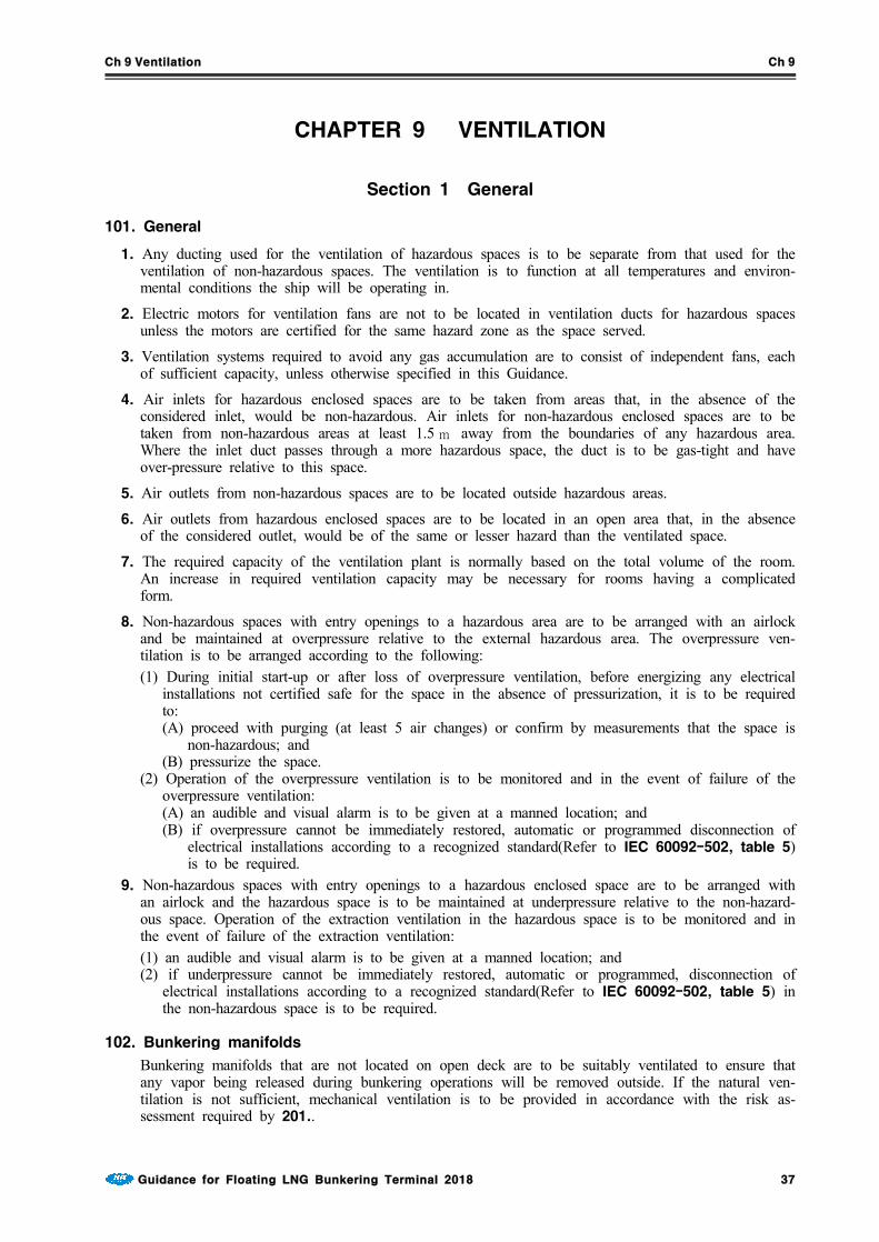
Ch 9 Ventilation Ch 9
Guidance for Floating LNG Bunkering Terminal 2018 37
CHAPTER 9 VENTILATION
Section 1 General
101. General
1. Any ducting used for the ventilation of hazardous spaces is to be separate from that used for the ventilation of non-hazardous spaces. The ventilation is to function at all temperatures and environ-mental conditions the ship will be operating in.
2. Electric motors for ventilation fans are not to be located in ventilation ducts for hazardous spaces unless the motors are certified for the same hazard zone as the space served.
3. Ventilation systems required to avoid any gas accumulation are to consist of independent fans, each of sufficient capacity, unless otherwise specified in this Guidance.
4. Air inlets for hazardous enclosed spaces are to be taken from areas that, in the absence of the considered inlet, would be non-hazardous. Air inlets for non-hazardous enclosed spaces are to be taken from non-hazardous areas at least 1.5 m away from the boundaries of any hazardous area. Where the inlet duct passes through a more hazardous space, the duct is to be gas-tight and have over-pressure relative to this space.
5. Air outlets from non-hazardous spaces are to be located outside hazardous areas.
6. Air outlets from hazardous enclosed spaces are to be located in an open area that, in the absence of the considered outlet, would be of the same or lesser hazard than the ventilated space.
7. The required capacity of the ventilation plant is normally based on the total volume of the room. An increase in required ventilation capacity may be necessary for rooms having a complicated form.
8. Non-hazardous spaces with entry openings to a hazardous area are to be arranged with an airlock and be maintained at overpressure relative to the external hazardous area. The overpressure ven-tilation is to be arranged according to the following:(1) During initial start-up or after loss of overpressure ventilation, before energizing any electrical
installations not certified safe for the space in the absence of pressurization, it is to be required to:(A) proceed with purging (at least 5 air changes) or confirm by measurements that the space is
non-hazardous; and(B) pressurize the space.
(2) Operation of the overpressure ventilation is to be monitored and in the event of failure of the overpressure ventilation:(A) an audible and visual alarm is to be given at a manned location; and(B) if overpressure cannot be immediately restored, automatic or programmed disconnection of
electrical installations according to a recognized standard(Refer to IEC 60092-502, table 5) is to be required.
9. Non-hazardous spaces with entry openings to a hazardous enclosed space are to be arranged with an airlock and the hazardous space is to be maintained at underpressure relative to the non-hazard-ous space. Operation of the extraction ventilation in the hazardous space is to be monitored and in the event of failure of the extraction ventilation:(1) an audible and visual alarm is to be given at a manned location; and (2) if underpressure cannot be immediately restored, automatic or programmed, disconnection of
electrical installations according to a recognized standard(Refer to IEC 60092-502, table 5) in the non-hazardous space is to be required.
102. Bunkering manifolds
Bunkering manifolds that are not located on open deck are to be suitably ventilated to ensure that any vapor being released during bunkering operations will be removed outside. If the natural ven-tilation is not sufficient, mechanical ventilation is to be provided in accordance with the risk as-sessment required by 201..

Ch 9 Ventilation Ch 9
38 Guidance for Floating LNG Bunkering Terminal 2018
Section 2 Mechanical Ventilation in the Cargo Area
201. Spaces required to be entered during normal cargo handling operations
1. Electric motor rooms, cargo compressor and pump-rooms, spaces containing cargo handling equip-ment and other enclosed spaces where cargo vapors may accumulate are to be fitted with fixed ar-tificial ventilation systems capable of being controlled from outside such spaces. The ventilation is to be run continuously to prevent the accumulation of toxic and/or flammable vapors, with a means of monitoring acceptable to the Society to be provided. A warning notice requiring the use of such ventilation prior to entering is to be placed outside the compartment.
2. Artificial ventilation inlets and outlets are to be arranged to ensure sufficient air movement through the space to avoid accumulation of flammable, toxic or asphyxiant vapors, and to ensure a safe working environment.
3. The ventilation system is to have a capacity of not less than 30 changes of air per hour, based upon the total volume of the space. As an exception, non-hazardous cargo control rooms may have eight changes of air per hour.
4. Where a space has an opening into an adjacent more hazardous space or area, it is to be main-tained at an overpressure. It may be made into a less hazardous space or non-hazardous space by overpressure protection in accordance with recognized standards.
5. Ventilation ducts, air intakes and exhaust outlets serving artificial ventilation systems are to be positioned in accordance with recognized standards.(eg., IEC 60092-502). Air inlets are to be lo-cated in non-hazardous areas and the construction of ventilation exhaust ducts is, for example, to be as shown in Fig 8.1 of the Guidance.
Fig 8.1 The consruction of
ventilation exhaust ducts
6. Ventilation ducts serving hazardous areas are not to be led through accommodation, service and machinery spaces or control stations, except as allowed in Pt 7, Ch 5, Sec 16 of Rules for theClassification of Steel Ships.
7. Electric motors' driving fans are to be placed outside the ventilation ducts that may contain flam-mable vapors. Ventilation fans are not to produce a source of ignition in either the ventilated space or the ventilation system associated with the space. For hazardous areas, ventilation fans and ducts, adjacent to the fans, are to be of non-sparking construction, as defined below: 【See Guidance】(1) impellers or housing of non-metallic construction, with due regard being paid to the elimination
of static electricity(2) impellers and housing of non-ferrous materials(3) impellers and housing of austenitic stainless steel(4) ferrous impellers and housing with design tip clearance of not less than 13 mm.Any combination of an aluminium or magnesium alloy fixed or rotating component and a ferrous fixed or rotating component, regardless of tip clearance, is considered a sparking hazard and is not to be used in these places.(5) The ventilation fans for motor rooms where electric motors to drive cargo compressors and car-
Ch 9 Ventilation Ch 9
Guidance for Floating LNG Bunkering Terminal 2018 39
go pumps are installed are to be complied following requirements (A) and (B) :(A) To have a ventilation capacity of not less then 30 air changes of the total volume of the
motor room per hour.(B) Electric motors driving ventilation fans are to conform to the relevant requirements in Pt 7,Ch 5, Sec 10 of Rules for the Classification of Steel Ships depending on the location of motors, and in addition, to the requirements for exterior-mounted type specified in Pt 8,Ch 12, 201. 4 (2) of Rules for the Classification of Steel Ships when motors are in-stalled in exposed spaces.
(5) Where electric motors for ventilation fans are certified for the same hazard zone as the space served, the motors may be located in ventilation ducts for hazardous space.
8. Where fans are required by this Section, full required ventilation capacity for each space are to be available after failure of any single fan, or spare parts are to be provided comprising a motor, starter spares and complete rotating element, including bearings of each type.
9. Protection screens of not more than 13 mm square mesh are to be fitted to outside openings of ventilation ducts.
10. Where spaces are protected by pressurization, the ventilation is to be designed and installed in ac-cordance with recognized standards.(eg., IEC 60092-502)
202. Spaces not normally entered
1. Enclosed spaces where cargo vapors may accumulate are to be capable of being ventilated to en-sure a safe environment when entry into them is necessary. This is to be capable of being ach-ieved without the need for prior entry.
2. For permanent installations, the capacity of 8 air changes per hour is to be provided and for port-able systems, the capacity of 16 air changes per hour.
3. Fans or blowers are to be clear of personnel access openings, and are to comply with Pt 7, Ch5, 1201. 7 of Rules for the Classification of Steel Ships.
4. For cargo hold spaces, natural ventilation alone is not acceptable.

Ch 10 Fire protection, Fire Extinction and Means of Escape Ch 10
Guidance for Floating LNG Bunkering Terminal 2018 41
CHAPTER 10 FIRE PROTECTION, FIRE EXTINCTIONAND MEANS OF ESCAPE
Section 1 General
101. Application
1. The requirements are to be in accordance with Pt 7, Ch 5, Sec 11 of Rules for theClassification of Steel Ships. However, the terminal which operates at berth and can be sup-ported form the shore may be loosened as follows.(1) In application to Pt 7, Ch 5, 1106. 1 of Rules for the Classification of Steel Ships, two
sets of fire-fighter's outfits may be accepted.(2) In application to Pt 8, Ch 8, 101. 3 (1) (B) of Rules for the Classification of Steel Ships,
emergency fire pump may be omitted where fire water from the shore is connected to onboard shore connection and is continuously provided onboard.
102. Bunkering manifold area
1. Water spray systems are to be installed at the bunkering manifold area in accordance with Pt 7,Ch 5, 1103. of Rules for the Classification of Steel Ships.
2. Dry chemical powder fire-extinguishing systems is to be installed at the bunkering manifold area in accordance with Pt 7, Ch 5, Ch 5 1104. of Rules for the Classification of Steel Ships.
Section 2 Means of Escape
201. Muster stations
1. General
The muster station is to be of sufficient area to accommodate the number of personnel to be gathered.
2. Materials
3. Muster stations
(2) The muster station is to be located in a safe location with respect to the processing equipment.(3) The muster station may be a meeting room inside the accommodations or may be part of the
lifeboat embarkation station.
202. Escape route
1. Materials
All materials that comprise the escape routes are to be of steel or equivalent material. 2. Escape route
(1) At least two means of escape are to be provided for all continuously manned areas, and areas that are used on a regular working basis.
(2) The two means of escape are to be through routes that minimize the possibility of having both routes blocked in an emergency situation.
(3) Escape routes are to have a minimum width of 700 mm. (4) Dead-end corridors exceeding 7 m in length are not permitted. (5) Dead-end corridors are defined as a pathway which (when used during an escape) has no exit.
3. Marking and lighting of escape routes
Escape route paths are to be properly identified and provided with adequate lighting.

Ch 10 Fire protection, Fire Extinction and Means of Escape Ch 10
42 Guidance for Floating LNG Bunkering Terminal 2018
4. Escape route plan
(1) An escape route plan is to be prominently displayed at various points in the unit. (2) Alternatively, this information may be included in the fire control plan.
203. Breathing Apparatus
1. The breathing apparatus for maintenance personnel is to have a minimum of 30 minutes air supply.
2. A designated safe area with proper supply of air is also to be provided and shown on the fire control plan.
204. Means of Embarkation
1. A unit is to have means of embarkation to allow personnel to leave the unit in an emergency.
2. The means of embarkation are to consist of at least two fixed ladders or stairways, widely sepa-rated, and extending from the main decks to the water line.
3. The ladders or stairways will preferably be located near lifeboat-launching stations.
4. Ladder construction is to be in accordance with the appropriate governmental authority, or other recognized standard.

Ch 11 Personnel Protection Ch 11
Guidance for Floating LNG Bunkering Terminal 2018 43
CHAPTER 11 PERSONNEL PROTECTION
Section 1 Personnel Protection
101. Protective equipment
1. Suitable protective equipment, including eye protection to a recognized national or international standard, is to be provided for protection of crew members engaged in normal cargo operations, taking into account the characteristics of the products being carried.
2. Personal protective and safety equipment required in this Section are to be kept in suitable, clearly marked lockers located in readily accessible places.
3. The compressed air equipment is to be inspected at least once a month by a responsible officer and the inspection logged in the ship's records. This equipment is also to be inspected and tested by a competent person at least once a year.
102. First-aid equipment
1. A stretcher that is suitable for hoisting an injured person from spaces below deck is to be kept in a readily accessible location.
2. The ship is to have onboard medical first-aid equipment, including oxygen resuscitation equipment, based on the requirements of the Medical First Aid Guide (MFAG) for the cargoes listed on the International Certificate of Fitness for the Carriage of Liquefied Gases in Bulk.
103. Safety equipment
1. Sufficient, but not less than three complete sets of safety equipment are to be provided in addition to the firefighter's outfits required by Pt 7, Ch 5, 1106. 1 of Rules for the Classification ofSteel Ships. Each set is to provide adequate personal protection to permit entry and work in a gas-filled space. This equipment is to take into account the nature of the cargoes, listed on the International Certificate of Fitness for the Carriage of Liquified Gases in Bulk.
2. Each complete set of safety equipment is to consist of:(1) one self-contained positive pressure air-breathing apparatus incorporating full face mask, not us-
ing stored oxygen and having a capacity of at least 1,200 L of free air. Each set is to be com-patible with that required by Pt 7, Ch 5, 1106. 1 of Rules for the Classification of SteelShips
(2) protective clothing, boots and gloves to a recognized standard(3) steel-cored rescue line with belt(4) explosion-proof lamp.
3. An adequate supply of compressed air is to be provided and is to consist of:(1) at least one fully charged spare air bottle for each breathing apparatus required by 1(2) an air compressor of adequate capacity capable of continuous operation, suitable for the supply
of high pressure air of breathable quality(3) a charging manifold capable of dealing with sufficient spare breathing apparatus air bottles for
the breathing apparatus required by 1.
104. Personnel protection requirements for individual products
1. Requirements of this Article are to apply to ships carrying products for which those paragraphs are listed in column "i" in the table of Pt 7, Ch 5, Sec 19 of Rules for the Classification ofSteel Ships.
2. Suitable respiratory and eye protection for emergency escape purposes are to be provided for every person on board, subject to the following:(1) filter-type respiratory protection is unacceptable;(2) self-contained breathing apparatus are to have at least a duration of service of 15 min(3) emergency escape respiratory protection is not to be used for firefighting or cargo-handling pur-
poses and is to be marked to that effect.

Ch 11 Personnel Protection Ch 11
44 Guidance for Floating LNG Bunkering Terminal 2018
3. One or more suitably marked decontamination showers and eyewash stations are to be available on deck, taking into account the size and layout of the ship. The showers and eyewashes are to be operable in all ambient conditions.
4. The protective clothing required under Pt 7, Ch 5, 1403. 2 (2) of Rules for the Classificationof Steel Ships is to be gastight.
Ch 12 Bunkering System Ch 12
Guidance for Floating LNG Bunkering Terminal 2018 45
CHAPTER 12 BUNKERING SYSTEM
Section 1 General
101. Application
1. This Chapter applies to all bunker arrangements, piping and accessories which are capable of han-dling liquefied natural gas.
102. General requirements
The following factors should be considered when designing the bunkering system.1. Compatibility of the bunkering device between the bunker terminal and the receiving vessel, such
as tank type or tank connection
2. Compatibility of bunkering terminals with safety devices (eg. ESD system) of the receiving vessels
3. Influence of relative movement due to ship's movement and surrounding environment such as wind, waves and algae
4. Bunkering procedures such as gas-free, purging, precooling, etc.
5. The difference in LNG transmission rate at the start stage, full loading and recharging of bunker-ing, and the rapid phase transition of LNG during bunkering
Section 2 Arrangements and Design of Bunkering Systems
201. Functional requirements
1. Bunkering systems are to be designed with suitable functionality for prevention, detection, control and mitigation of leakage of LNG and NG affecting the ship and personnel safety.
2. Systems are to be able to be drained, purged and inerted before connecting or disconnecting trans-fer systems.
3. Systems are to be designed to prevent from damage due to pressure increase in systems which may be isolated in a LNG full condition.
4. Substitution of systems required in this Annex with operational or procedural measures is not permitted.
202. Bunkering manifold area
1. The bunkering manifold area is to be located on the open deck so that sufficient natural ventilation is provided.
2. Drip trays are to be fitted below LNG bunkering connection and where leakage may occur in ac-cordance with the followings.(1) Drip trays are to be made of suitable material for low temperatures.(2) The drip tray is to be thermally insulated from the ship's structure so that the surrounding hull
or deck structures are not exposed to unacceptable cooling, in case of leakage of liquid fuel.(3) The tray is to be fitted with a drain valve to enable rain water to be drained over the ship's
side.(4) The tray is to have a sufficient capacity to ensure that the maximum amount of spill according
to the risk assessment can be handled.3. A water distribution system is to be fitted in way of the hull under the bunker connections to pro-
vide a low-pressure water curtain for additional protection of the hull steel and the ship's side structure. This system is to be operated when cargo transfer is in progress.
4. The bunker connections are to be observable from the navigation bridge and bunker operation con-

Ch 12 Bunkering System Ch 12
46 Guidance for Floating LNG Bunkering Terminal 2018
trol position by providing permanent watch or CCTV during the transfer.
203. Bunkering manifold
1. Safe working load of The bunkering manifold is to be designed to withstand the external loads during bunkering operation.
2. Information about maximum safe working load of bunkering connection is to be detailed in the op-eration manuals and posted at the bunker station.
3. Connections for vapor return from the receiving ship are to be provided.
4. A manually operated stop valve and a remote operated shutdown valve in series, or a combined manually operated and remote valve, are to be fitted in every bunkering line including vapor line close to the manifold connecting point. The remote valve is to be operable from the control loca-tion for bunkering operations or another safe location.
5. All pipelines or components which may be isolated in a liquid full condition are to be protected with relief valves for thermal expansion and evaporation.
6. Manifold connections not being used for bunker transfer operations are to be blanked with blind flanges suitable for the design pressure.
204. Cargo tank loading
1. Cargo tanks of the bunkering ship are to be assessed for all partial loading conditions considering abortion of bunkering operation at any stage in case of emergency such that there are no opera-tional limits on partial loading.
2. Where there are no operational limits on partial loading, such operational limits are subject to ap-proval and are to be detailed in the operation manuals.
205. vapor return systems
1. The ship assigned with VRS notation in accordance with 102. 2 is to be provided with arrange-ments for handling excess vapor to protect fuel tank of receiving ship from over pressure.
2. Vapor returned from the receiving ship may be handled by one of the following methods:(1) reliquefaction of vapors;(2) thermal oxidation of vapors;(3) pressure accumulation; or(4) a combination of the above
3. The capacity of vapor return systems is to be sufficient for handling excess vapor returned from the receiving ship.
4. Reliquefaction plants and gas combustion units are to be in accordance with Pt 7, Ch 5, 703. and 704. of Rules for the Classification of Steel Ships.
5. Vapor return process piping is to be adequately separated from other cargo process piping to avoid over pressure of cargo system on the bunkering ship.
6. Control and monitoring of the vapor return system is to be integrated into the control and monitor-ing system of bunkering systems and to be capable of varying LNG delivery rates in consideration of the monitored vapor return system parameters.
7. Calculations for the maximum vapor return flow rate, pressure and corresponding tank pressure management details, are to be submitted and summary information is to be detailed in the operation manuals.
206. Electrical insulation
1. Inter-vessel electrical isolation between the bunkering ship and the receiving ship is to be main-tained during transfer to reduce high-energy sparks being produced by the electrical potential differ-

Ch 12 Bunkering System Ch 12
Guidance for Floating LNG Bunkering Terminal 2018 47
ence between the hulls.
2. Each transfer connection is to have insulation flange to maintain electrical isolation. Insulation flange shall have resistance of at least 1 kohm to limit current flow but less than 100 Mohm to dissipate static charge.
Section 3 Bunker Transfer Systems
301. General
1. The connections for LNG transfer and vapor return are to be fitted with manually operated stop valve and a remotely/automatically operated valve fitted in series.
2. The manifold is to be designed to withstand the external loads during cargo transfer. Safe working load of the manifold is to meet the Manifold recommendations for liquefied gas car-riers(OCIMF).
3. Information about maximum safe working load of the manifold is to be posted at the manifold area.
4. Means are to be provided to drain residual LNG in the bunkering systems to cargo tanks.
302. Transfer arms
1. The length and the configuration of the transfer arms are to allow for the connection of the termi-nal's manifold to the ship's cargo manifold. The connection is to allow for free movement within the operating envelope.
2. Transfer arms are to be designed in consideration of the followings.(1) acceleration forces acting on the transfer arm(2) permissible manifold loadings(3) arm working envelope(4) arm support arrangement in operation and storage condition(5) the effect of hull vibration on the arm(6) vertical and horizontal ship movement(7) allowable flow rate and pressure drop
3. Piping is to be arranged to avoid excessive stresses due to thermal movement and from movements of the tank and hull structure.
4. All piping supports are to be adequately designed so that stresses in the piping and the structure are within allowable limits for all attitudes and positions.
5. Emergency release systems are to be in accordance with 403..
6. ISO 16904 is to be applied for design and construction of transfer arms.
303. Transfer hoses
1. Transfer hoses
(1) Hoses are to be designed for a bursting pressure not less than five times the maximum working pressure.
(2) Material of hoses is to be compatible with the cargo and suitable for the cargo temperature.(3) The overall hose length is to be sufficient to meet both storage and operation condition.(4) Hoses for LNG transfer are to be protected from over pressure by relief valves fitted outboard
manifold valve.(5) In determining the size and length of the hoses to be used, the followings are to be considered
(A) maximum allowable bend radius of the hose(B) horizontal distance between the ships(C) difference in fore and after alignment(manifold offset)(D) distance between the manifold and the ship's side(E) vertical and horizontal ship movement

Ch 12 Bunkering System Ch 12
48 Guidance for Floating LNG Bunkering Terminal 2018
(F) relative change in freeboard between the ships(G) allowable flow rate and pressure drop(H) hose supporting and handling equipment
2. Hose supporting and handling equipments
(1) The bunkering ship is to fitted with equipment supporting hoses during the transfer and han-dling hoses after activation of emergency release coupling.
(2) Hose supporting and handling equipments are to be in accordance with Pt 9, Ch 2 of Rulesfor the Classification of Steel Ships.
(3) Hose supports or cradles are to be arranged in consideration of hose bend radius.3. Hose are to be accordance with the standards recognized by the Society such as EN 1474-2, EN
12434 or BS 4089. Also, strictly adhere to the manufacturer's instructions.
304. Coupling and spool piece
1. Standard
Couplings and spool pieces used in bunkering operations are to be designed in accordance with ISO 16904 and EN 1474-3 or other applicable standards.
2. Spool piece
When connecting spool pieces to connectors of various sizes and shapes, they must be installed and tested before bunkering. Through the leak test, the batch containing the spool piece must be completely deactivated and the seal of the gas must be verified before transport.
Section 4 Control, Monitoring and Safety Systems
401. General
1. Control, monitoring and safety Systems are to be provided to maintain operations within preset pa-rameters for bunkering operations
2. The bunkering control and monitoring system is to be designed so that no single control system component failure or single fault condition is to lead to loss of control of bunkering operations or result in an unsafe situation. A Failure Modes Effects Analysis (FMEA) is to be carried out and documented.
3. Control of bunkering is to be possible from a safe location in regard to bunkering operations.
4. Safety function for parameter monitored during bunkering operation is to be in accordance with 402. 2, 3 and 403. 1.
402. Monitoring, alarm and control systems
1. Visible and audible alarms are to be provide on bunkering control station.
2. Alarms are to be activated in the following cases.(1) Low pressure in the supply tank(2) Sudden pressure drop at the transfer pump discharge (3) High level in the receiving tank(4) High pressure in the receiving tank(5) LNG leakage in manifold area (6) Gas detection in the ducting around the bunkering lines at 30% LEL(7) Gas detection in enclosed cargo machinery spaces at 30% LEL(8) Manual or automatic activation of the emergency shutdown system(9) Manual or automatic activation of the emergency release system(10) Safe working envelope of the loading arm exceeded(11) Fire detection on receiving ship or bunkering ship(12) Electrical power failure

Ch 12 Bunkering System Ch 12
Guidance for Floating LNG Bunkering Terminal 2018 49
3. Where transfer arms are used as transfer systems, in addition to Par. 2, the followings are be complied with.(1) A system of constant monitoring of the position of arms is to be installed to provide real time
information to the operator and receiving ship. (2) For the hydraulic systems of the transfer arm, visible and audible alarms are to be activated in
the following cases. (A) low pressure in hydraulic accumulators;(B) abnormal pressure in actuators chambers;(C) low system oil level in tank;(D) low nitrogen pressure in accumulators.
403. Emergency shutdown systems
1. Emergency shutdown system is to safely stop and isolate the bunker transfer between bunkering ship and receiving ship in the following cases:(1) Low pressure in the supply tank(2) Sudden pressure drop at the transfer pump discharge (3) High level in the receiving tank(4) High pressure in the receiving tank(5) LNG leakage in manifold area (6) Gas detection in the ducting around the bunkering lines at 60% LEL(7) Gas detection in enclosed cargo machinery spaces at 60% LEL(8) Manual or automatic activation of the emergency shutdown system(9) Manual or automatic activation of the emergency release system(10) Safe working envelope of the loading arm exceeded(11) Fire detection on receiving ship or bunkering ship(12) Electrical power failure
2. Activation of emergency shutdown system is to initiates the following:(1) shut-down of cargo transfer pump and vapor return compressor(2) closure of emergency shutdown valve; The closing time of the valve is to be considered so that
the surge pressure in the transfer piping is not to be greater than allowable pressure.3. A functional flow chart of the emergency shutdown system and related systems is to be provided
at the bunkering control station and cargo control station or bridge, as applicable.
4. Activation of the emergency shutdown system is to be controllable from both bunkering ship and receiving ship.
5. Emergency shutdown systems of the bunkering ship and the receiving ship are to be linked to en-sure the co-ordinated operation on both ships. This ESD link is to be fail-safe.
6. The bunkering system is not to be resumed until the transfer system and associated safety systems are returned to normal operation condition.
7. As a minimum, the emergency shutdown system is to be capable of manual operation in the followings.(1) bunkering control station(2) cargo control station(3) navigation bridge(3) navigation bridge(4) at least two strategic positions around the bunker delivery area.
404. Emergency release systems
1. Emergency release systems are to be capable of rapidly and automatically disconnecting the transfer system from the ship to protect the transfer system when exceeding design loads in any direction.
2. Emergency release systems are to be composed with emergency release coupling and two self-clos-ing shutoff valves and each valve is fitted at each side of the coupling to minimize cargo leakage when the coupling is activated.
3. Emergency release systems are to be controllable from both bunkering ship and receiving ship.

Ch 12 Bunkering System Ch 12
50 Guidance for Floating LNG Bunkering Terminal 2018
4. Emergency release systems is to be of powered type and the actuating power is to have reserve storage of energy sufficient for disconnection of all transfer lines in case the main source of actuat-ing power becomes unavailable (e.g. in case of black-out)
5. Emergency release systems is to be capable to be activated manually on local location and at least two remote locations including bunker control station.
6. When initiation of the emergency release system is to result in the simultaneous closing of inter-locking isolating valves of emergency release system, followed by the emergency release coupling separation, the followings are to be complied with to prevent hull and transfer system being damaged. (1) Where transfer arms are used, the disconnected arms are to retract behind the berthing line and
shall lock hydraulically.(2) Where transfer hoses are used, the disconnected hoses are to be supported by cranes or other
measures are to be taken to prevent hull and hose being damaged. 7. Manual or automatic activation of the emergency release system is to be inhibited without prior op-
eration of the emergency shutdown system.
Section 5 Communication and Lighting Systems
501. Communication systems
1. A communication system is to be provided between the bunkering facility and the receiving ship.
2. A communication system is to be provided with back-up.
3. The components of the communication system located in hazardous area are to be of certified safe type.
4. Where portable radios are used for communication, they are to be of certified safe type for hazard-ous area.
502. Lighting Systems
It should be illuminated brightly. Zone A where the following equipment is installed :1. Bunker hose using LNG
2. Emergency shut down button of ESD system
3. Communication system
4. Fire fight equipment
Section 6 Operational Requirements
601. General
1. Before any bunkering operation commences, a pre-bunkering operations meeting is to take place be-tween the person in charge at the bunkering ship and the persons in charge at the receiving ship and they shall:(1) agree in writing the transfer procedure, including cooling down and if necessary, gassing up; the
maximum transfer rate at all stages and volume to be transferred;(2) agree in writing action to be taken in an emergency; and(3) complete and sign the bunker checklist. Form and items of bunkering checklist are to be in ac-
cordance with IAPH 'LNG Bunkering Checklist - Ship to Ship'.2. Effective communications are to be maintained throughout the operation.
3. Essential cargo handling controls and alarms are to be checked and tested prior to bunkering operations.

Ch 12 Bunkering System Ch 12
Guidance for Floating LNG Bunkering Terminal 2018 51
602. Operation manuals
1. The ship is to be provided with bunkering operation manuals approved by the Society.
2. The contents of bunkering operation manuals is to include:(1) preparation before the bunkering(2) information to be exchanged between bunkering vessel and receiving ship prior to operation(3) hose or arm handling guidelines(4) procedures for connection including line inerting and tightness test(5) preparations for start of bunkering including preparedness of fire-fighting, tightness testing, estab-
lishing communications, allocation of personnel and responsibilities(6) pre-cooling of transfer connections and transfer procedures(7) draining of the pipeline, purging and disconnection on completion of the transfer(8) operational restrictions to prevent dangerous pressure surge effect in the pipes(9) fire safety during the transfer(10) procedures for raising alarms(11) procedures in case of communications failure(12) suspension of operation during emergencies(13) procedures for authorization of ERS activation(14) emergency procedures for the followings:
(A) gas fuel leakage(B) termination of the bunkering and emergency disconnection(C) response in case of unintentional disconnection of ERS
(15) vapor return management plan(16) operational envelope of bunkering ship

GUIDANCE FOR
FLOATING LNG
BUNKERING TERMINAL
Published byKR
36, Myeongji ocean city 9-ro, Gangseo-gu,BUSAN, KOREA
TEL : +82 70 8799 7114FAX : +82 70 8799 8999
Website : http://www.krs.co.kr
CopyrightⒸ 2018, KR
Reproduction of this Guidance in whole or in parts is pro-hibited without permission of the publisher.