hw # 6 /tutorial # 6 wrf chapter 20; wwwr chapters 21 & · pdf filewrf chapter 20; wwwr...
TRANSCRIPT
HW # 6 /Tutorial # 6
WRF Chapter 20; WWWR Chapters 21 & 22
ID Chapters 10 & 11
• Tutorial # 6
• WRF#20.6; WWWR#21.14, WRF#20.7; WWWR#21.19, 22.3, 22.15.
• To be discussed 6 March, 2018.
• By either volunteer or class list.
Boiling and Condensation
Boiling
Two basic types of boiling:
• Pool boiling
– Occurs on heated surface submerged in a liquid pool
which is not agitated
• Flow boiling
– Occurs in flowing stream
– Boiling surface may be a portion of flow passage
– Flow of liquid and vapor important type of 2 phase
flow
Regimes of Boiling
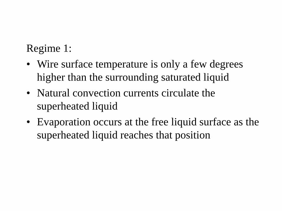
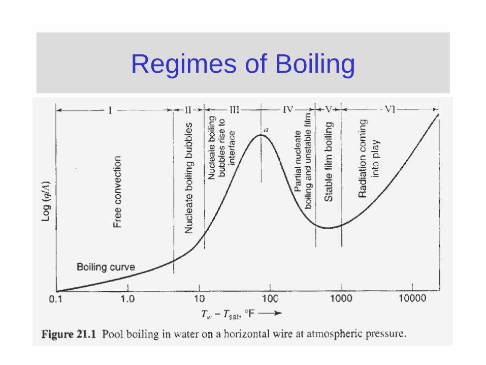
Regime 1:
• Wire surface temperature is only a few degrees
higher than the surrounding saturated liquid
• Natural convection currents circulate the
superheated liquid
• Evaporation occurs at the free liquid surface as the
superheated liquid reaches that position
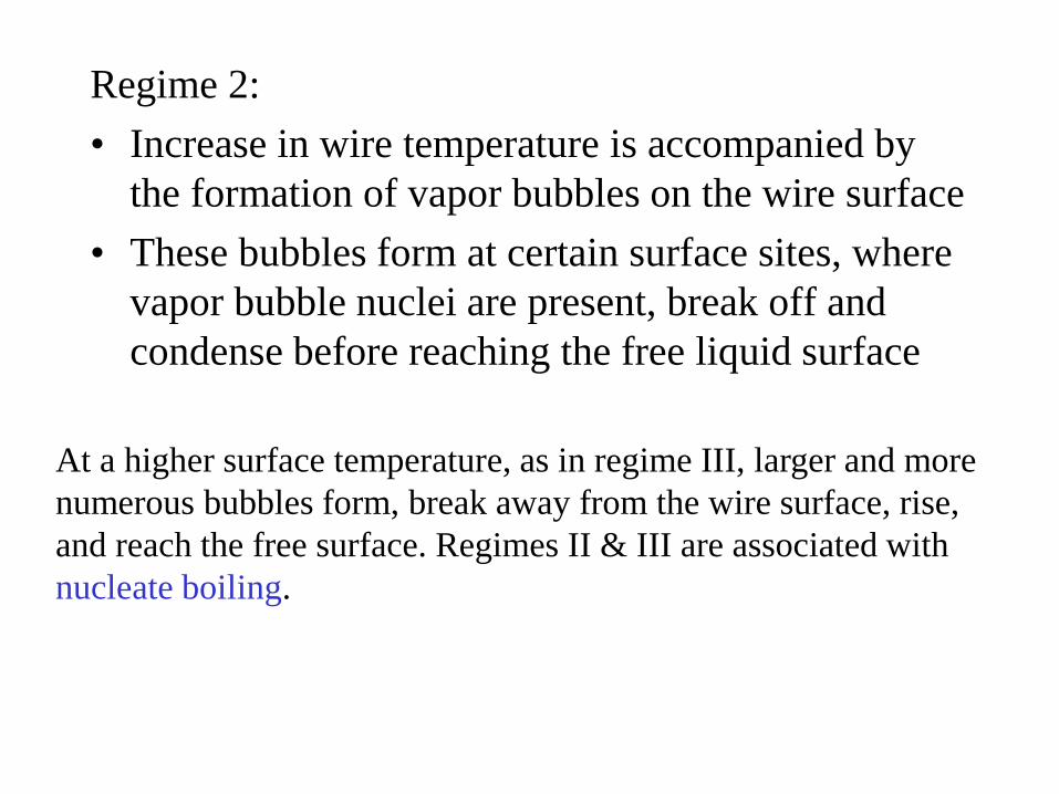
Regime 2:
• Increase in wire temperature is accompanied by
the formation of vapor bubbles on the wire surface
• These bubbles form at certain surface sites, where
vapor bubble nuclei are present, break off and
condense before reaching the free liquid surface
At a higher surface temperature, as in regime III, larger and more
numerous bubbles form, break away from the wire surface, rise,
and reach the free surface. Regimes II & III are associated with
nucleate boiling.
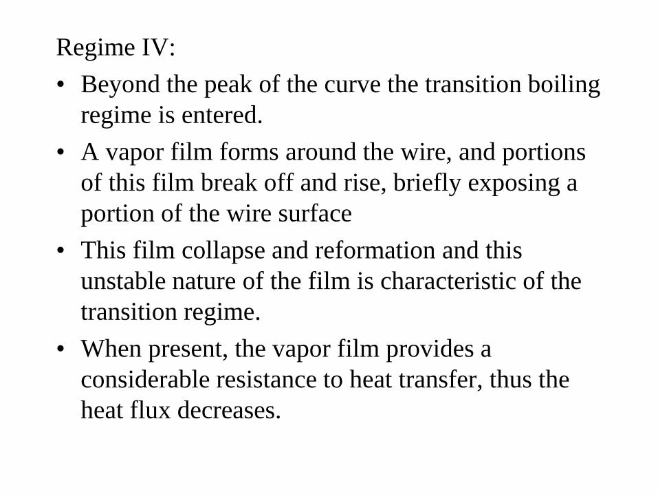
Regime IV:
• Beyond the peak of the curve the transition boiling
regime is entered.
• A vapor film forms around the wire, and portions
of this film break off and rise, briefly exposing a
portion of the wire surface
• This film collapse and reformation and this
unstable nature of the film is characteristic of the
transition regime.
• When present, the vapor film provides a
considerable resistance to heat transfer, thus the
heat flux decreases.
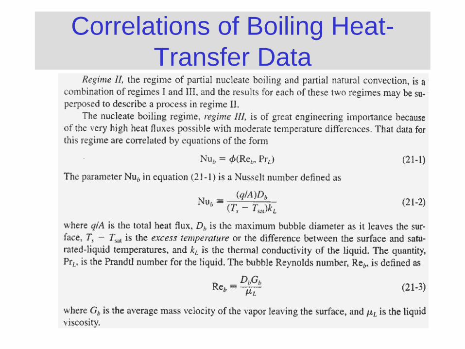
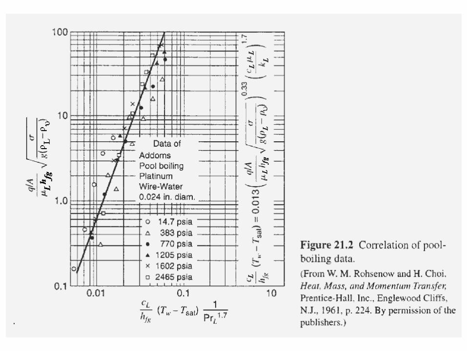
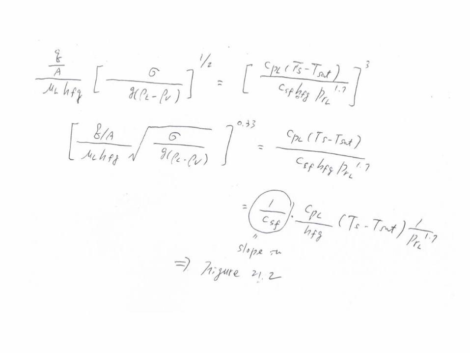
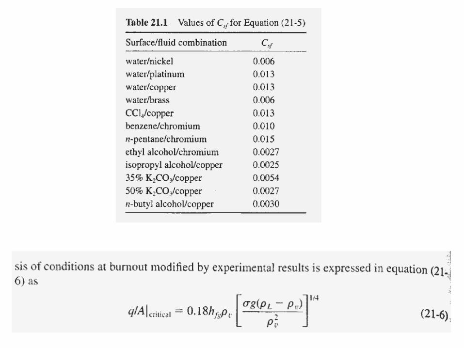
Correlations of Boiling Heat-
Transfer Data
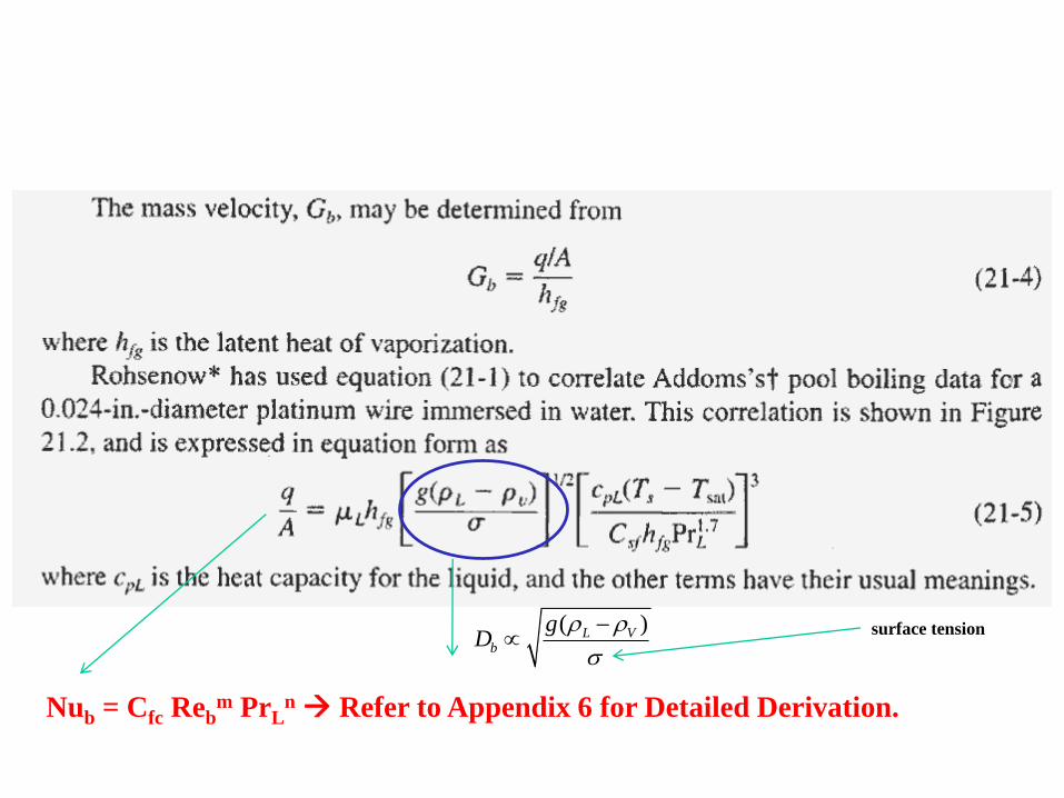
( )L Vb
gD
Nub = Cfc Rebm PrL
n Refer to Appendix 6 for Detailed Derivation.
surface tension
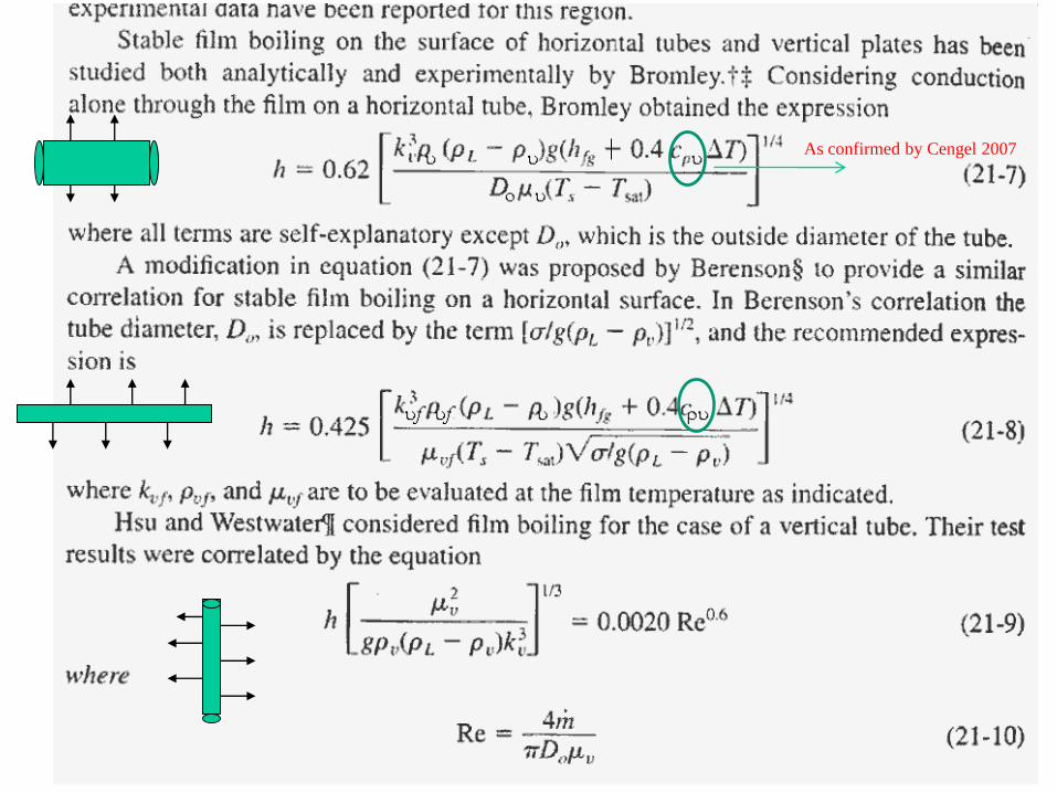
As confirmed by Cengel 2007
Condensation
• Occurs when a vapor contacts a surface
which is at a temperature below the
saturation temperature of the vapor.
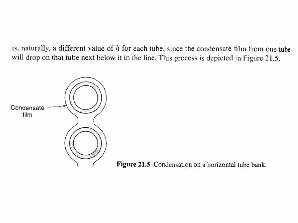
• When the liquid condensate forms on the
surface, it will flow under the influence of
gravity.
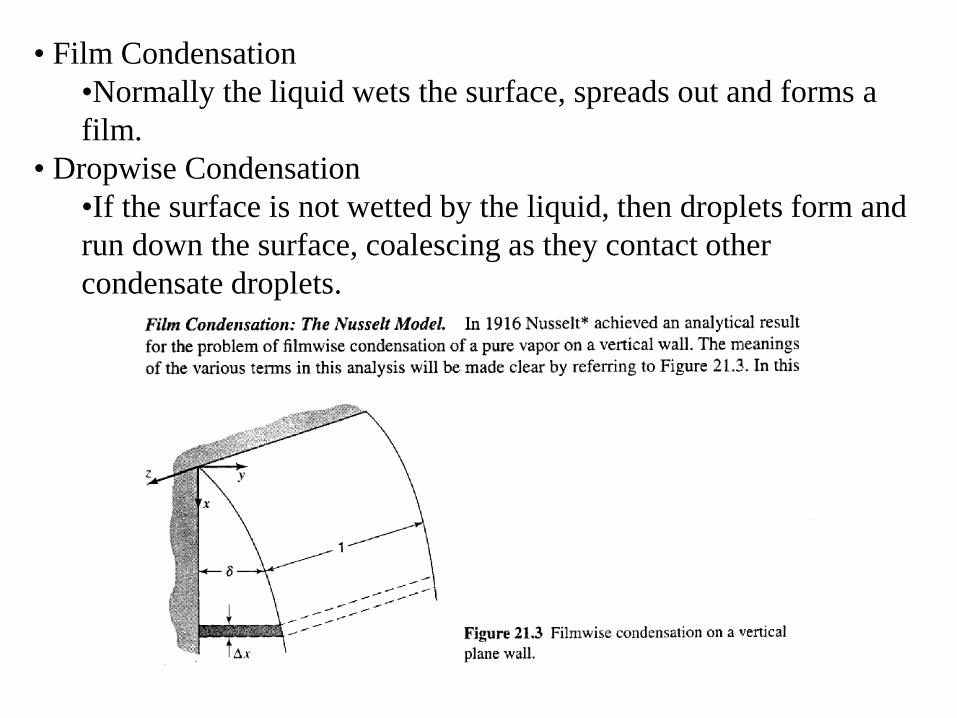
• Film Condensation
•Normally the liquid wets the surface, spreads out and forms a
film.
• Dropwise Condensation
•If the surface is not wetted by the liquid, then droplets form and
run down the surface, coalescing as they contact other
condensate droplets.
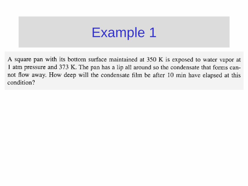
Example 1

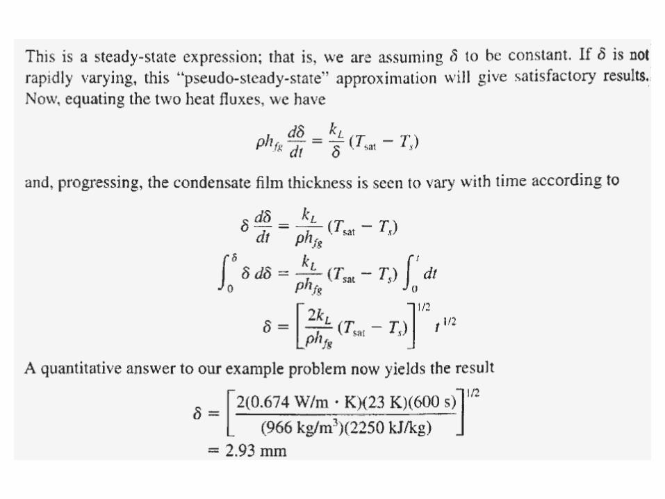
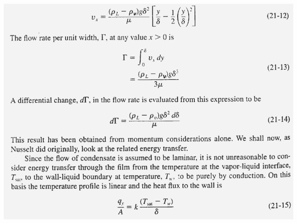
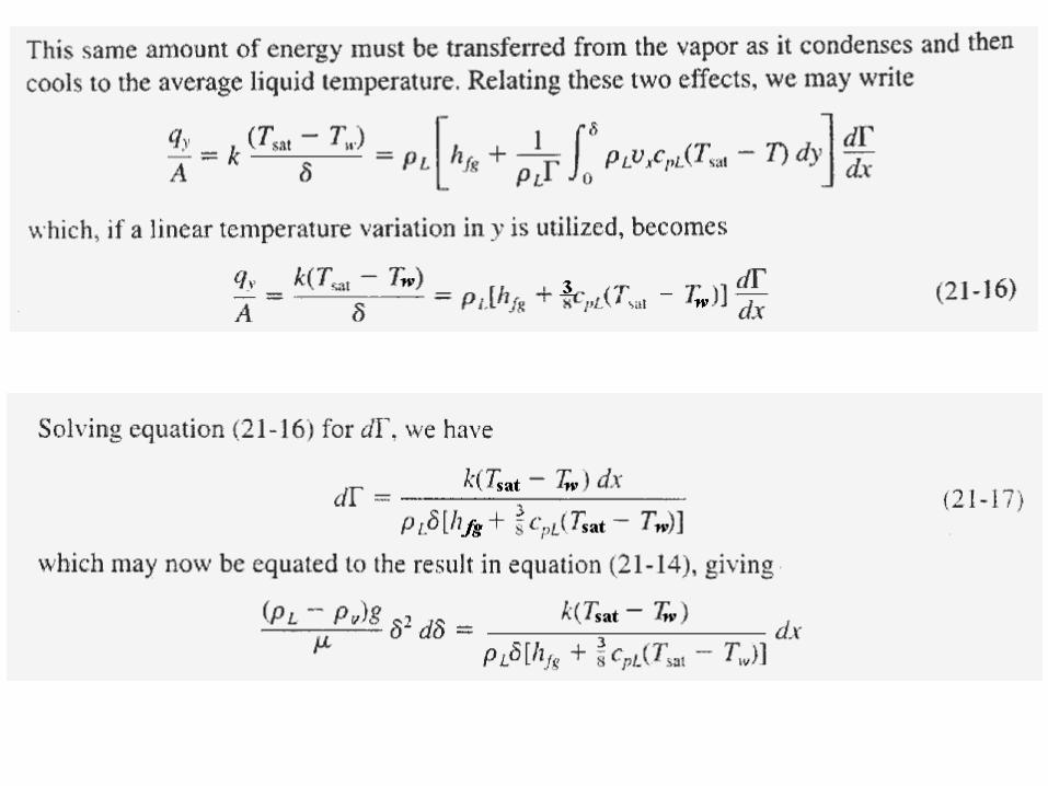
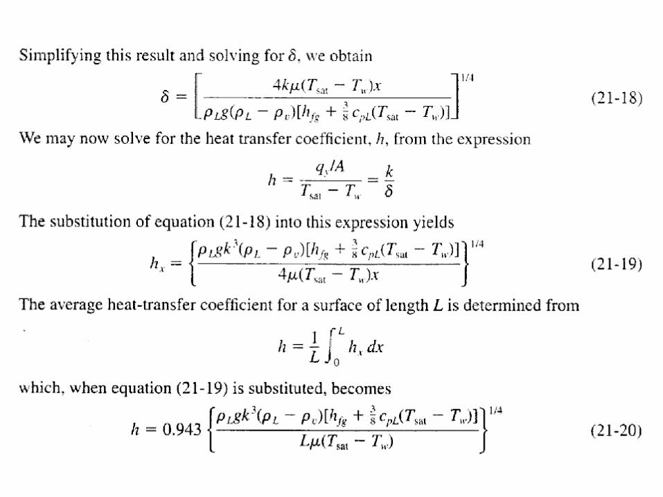
Film Condensation:
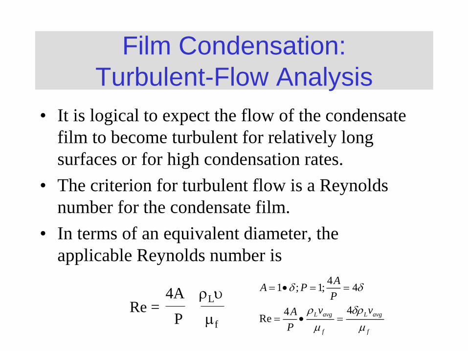
Turbulent-Flow Analysis
• It is logical to expect the flow of the condensate
film to become turbulent for relatively long
surfaces or for high condensation rates.
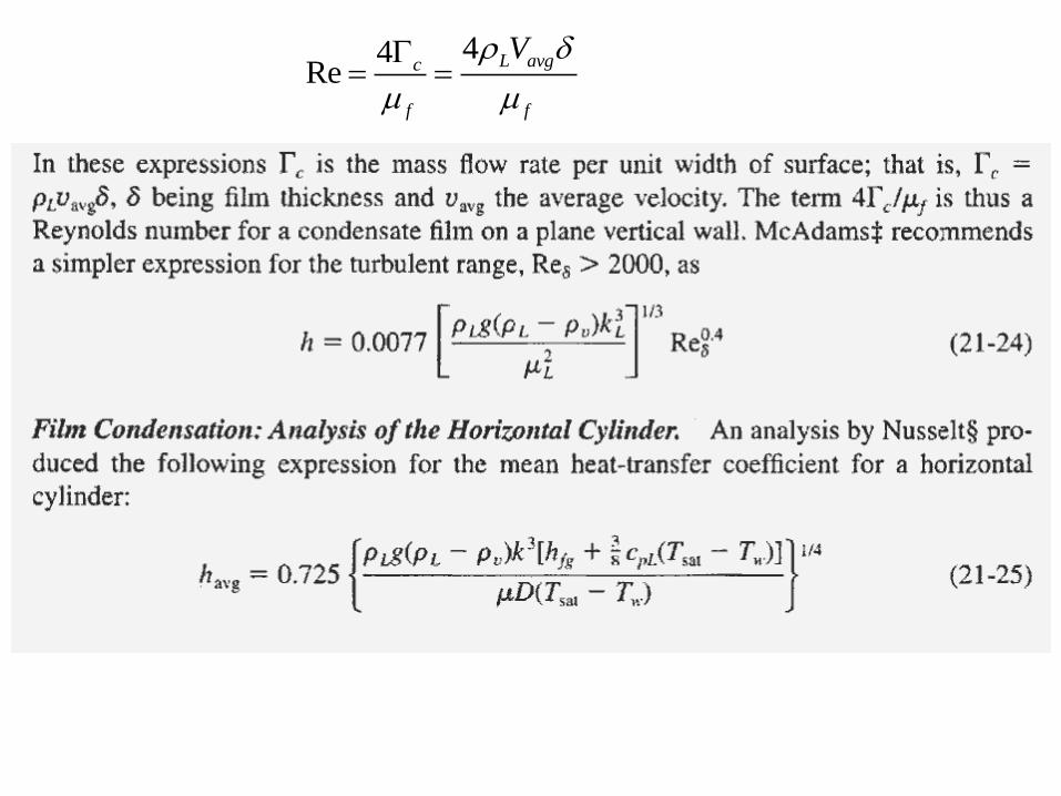
• The criterion for turbulent flow is a Reynolds
number for the condensate film.
• In terms of an equivalent diameter, the
applicable Reynolds number is
Re = 4A Lu
P mf
41 ; 1; 4
44Re
L avg L avg
f f
AA P
P
v vA
P
m m
44Re
L avgc
f f
V
m m
44Re
L avgc
f f
V
m m
Dropwise Condensation
Dropwise Condensation
• Associated with higher heat-transfer
coefficients than filmwise condensation
phenomenon.
• Attractive phenomenon for applications
where extremely large heat-transfer rates
are desired.
Heat Transfer Equipment
• Single-pass heat exchanger – fluid flows through
only once.
• Parallel or Co-current flow – fluids flow in the
same direction.
• Countercurrent flow or Counterflow - fluids flow
in opposite directions.
• Crossflow – two fluids flow at right angles to one
another.
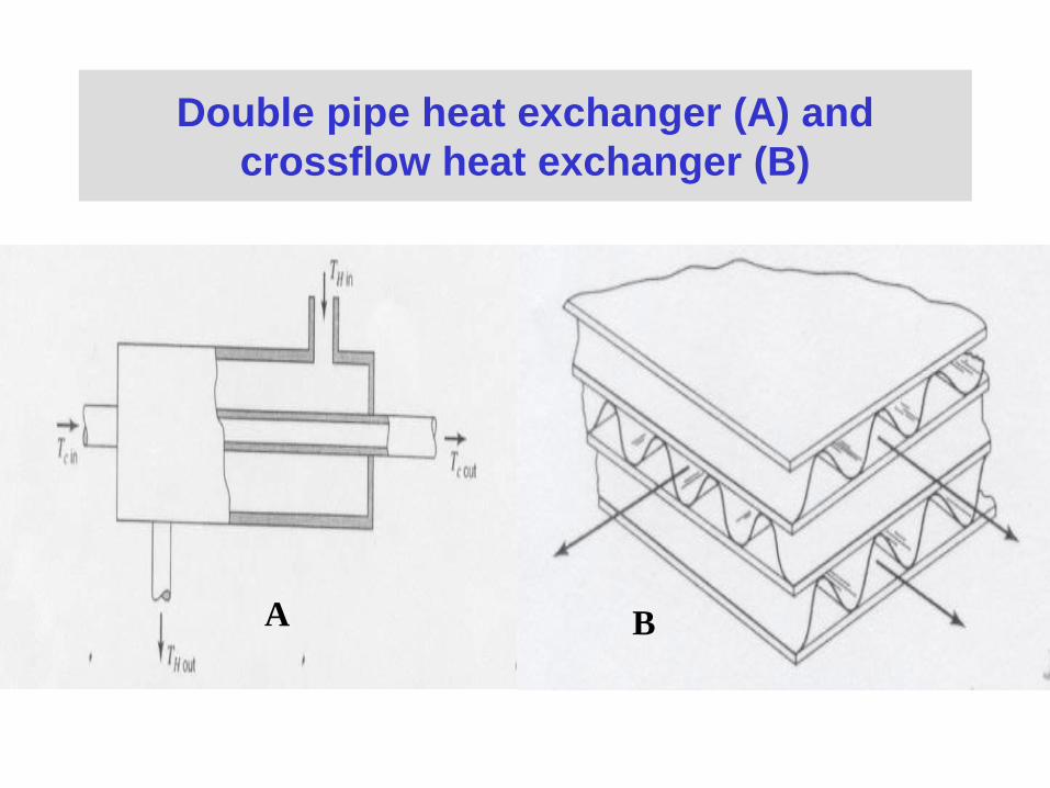
Double pipe heat exchanger (A) and
crossflow heat exchanger (B)
A B

Shell-and-tube Arrangement
• E.g. Tube-side fluid makes two passes, shell-side fluid
makes one pass.
• Good mixing of the shell-side fluid makes one pass.
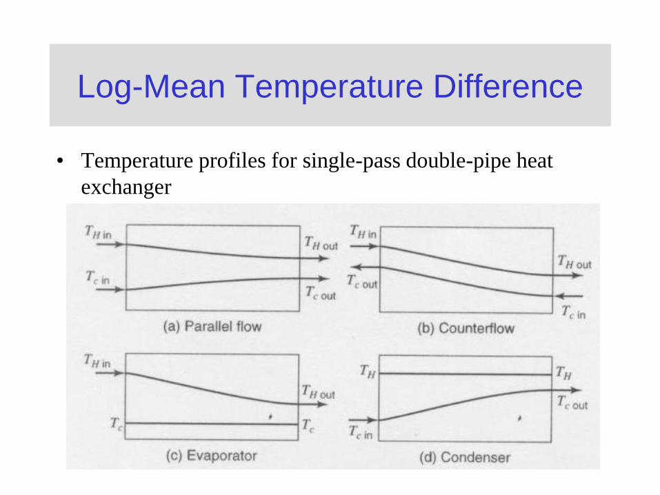
Log-Mean Temperature Difference
• Temperature profiles for single-pass double-pipe heat
exchanger
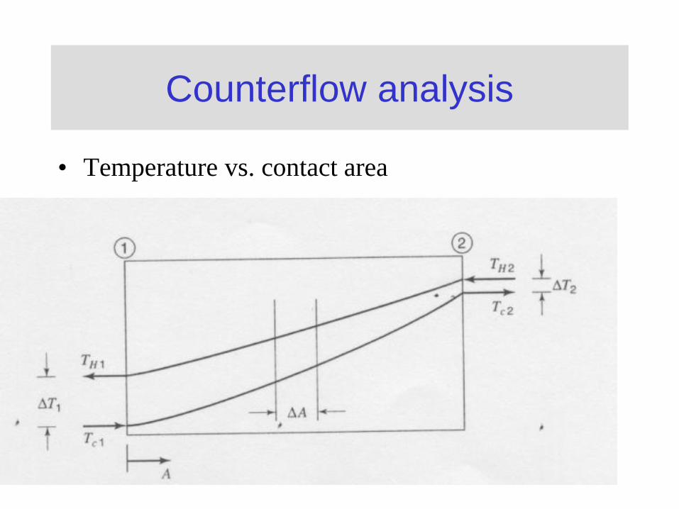
Counterflow analysis
• Temperature vs. contact area
Log-Mean Temperature Difference (continued)
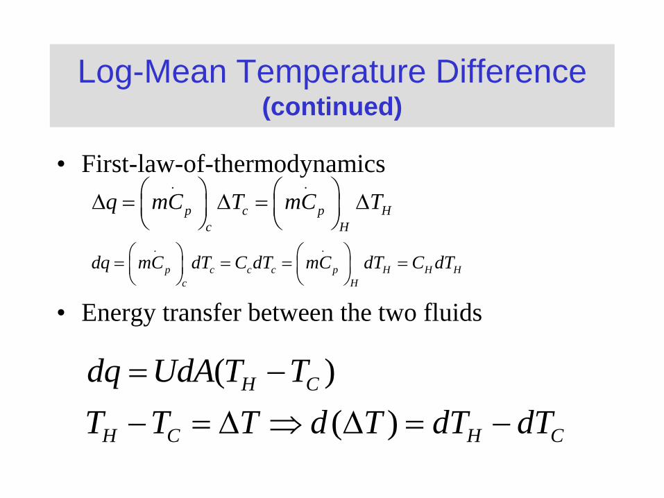
• First-law-of-thermodynamics
• Energy transfer between the two fluids
. .
p c p H
c H
q mC T mC T
. .
p c c c p H H H
c H
dq mC dT C dT mC dT C dT
( )
( )
H C
H C H C
dq UdA T T
T T T d T dT dT
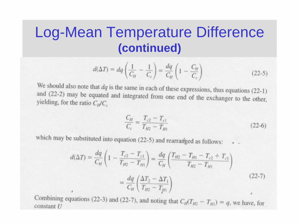
Log-Mean Temperature Difference (continued)
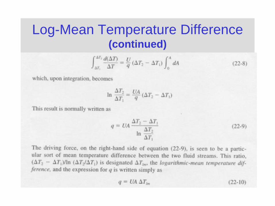
Log-Mean Temperature Difference (continued)
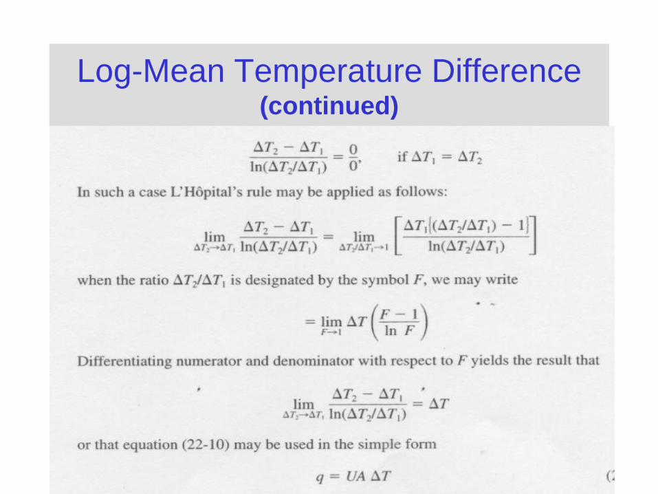
Log-Mean Temperature Difference (continued)
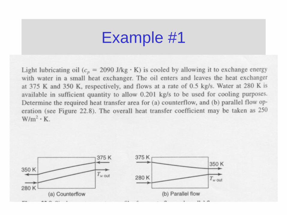
Example #1
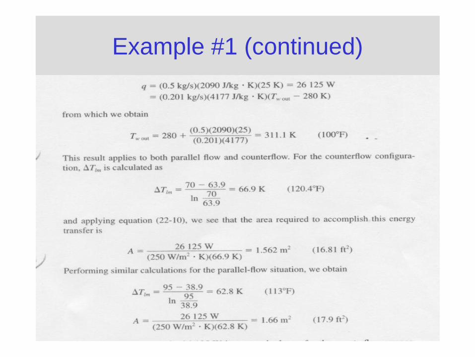
Example #1 (continued)
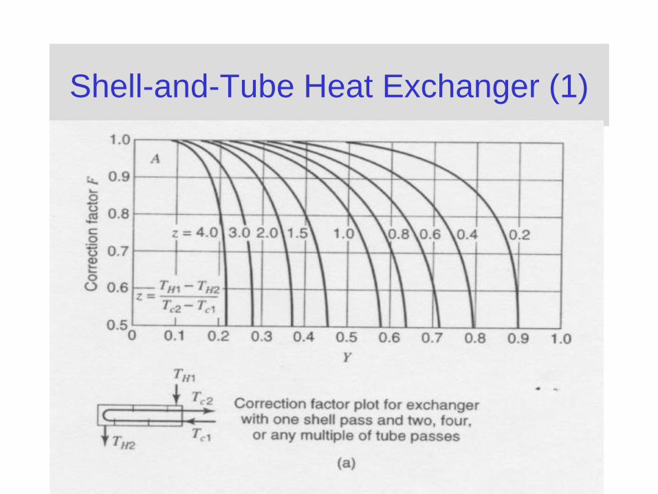
Shell-and-Tube Heat Exchanger (1)
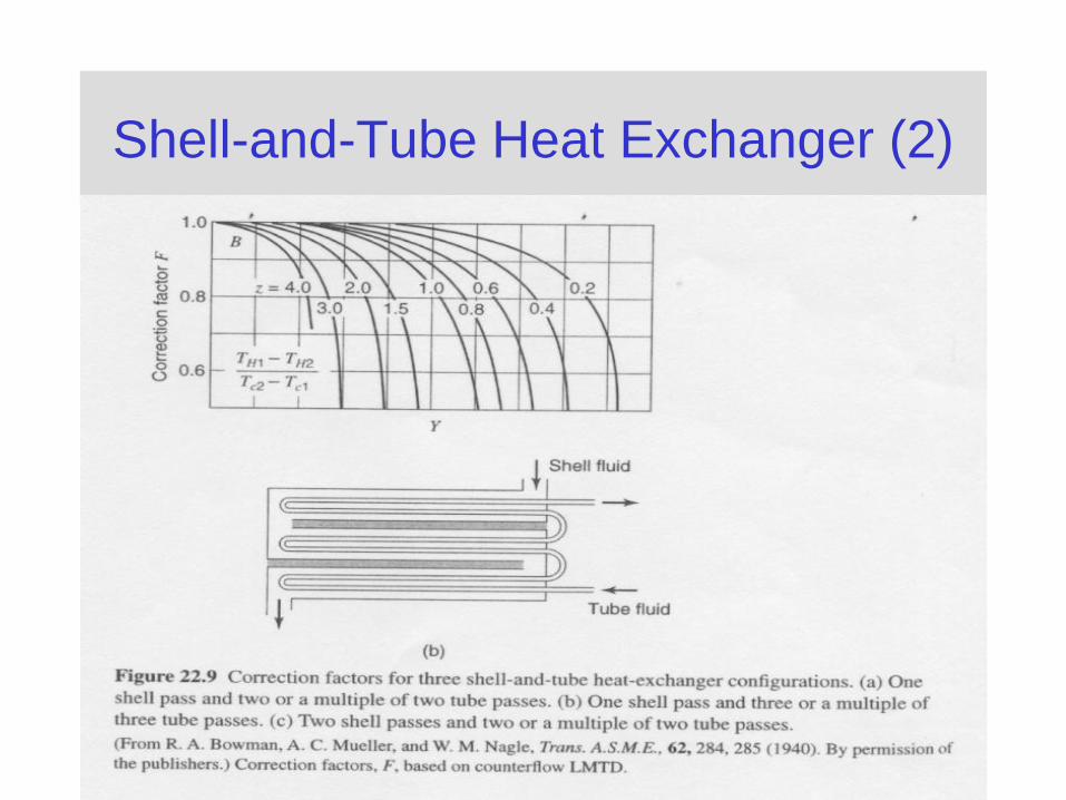
Shell-and-Tube Heat Exchanger (2)
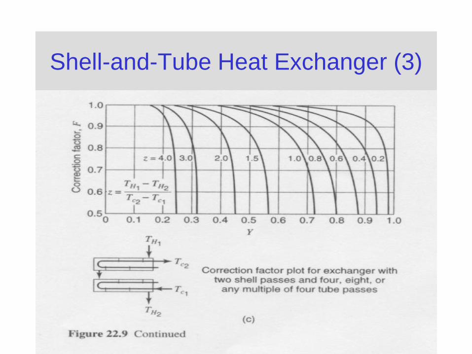
Shell-and-Tube Heat Exchanger (3)
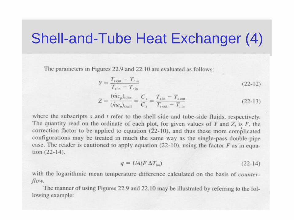
Shell-and-Tube Heat Exchanger (4)
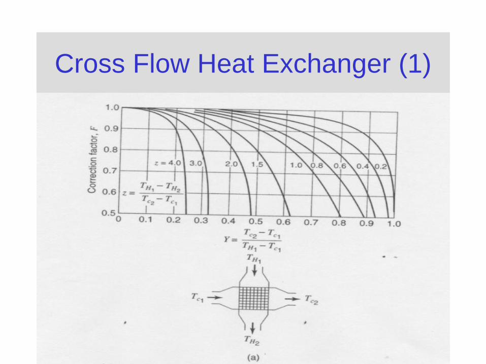
Cross Flow Heat Exchanger (1)
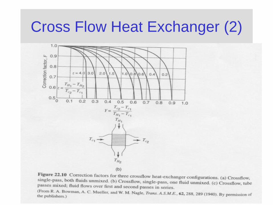
Cross Flow Heat Exchanger (2)
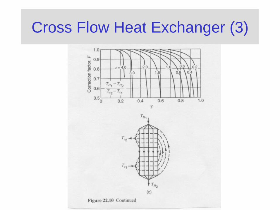
Cross Flow Heat Exchanger (3)
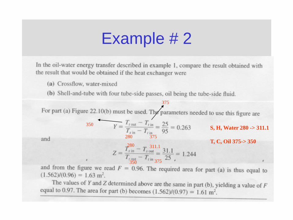
Example # 2
350
375
280 375
280 311.1
350 375
S, H, Water 280 -> 311.1
T, C, Oil 375-> 350