human skull shape and masticatory induced stress: objective
TRANSCRIPT
Human skull shape and masticatory induced stress:
Objective comparison through the use of non-rigid
registration
G. J. Jansen van Rensburg1,2, S. Kok1, D. N. Wilke2
1 Modelling and Digital Science, The Council for Scienti�c and Industrial Research, South Africa([email protected])2 Department of Mechanical and Aeronautical Engineering, University of Pretoria
Summary
Variation in masticatory induced stress, caused by shape changes in the human skull, is quanti�edin this article. A comparison on masticatory induced stress is presented subject to a variationin human skull shape. Non-rigid registration is employed to obtain appropriate computationaldomain representations. This procedure allows the isolation of shape from other variations thatcould a�ect the results. An added bene�t, revealed through the use of non-rigid registration toacquire appropriate domain representation, is the possibility of direct and objective comparisonand manipulation. The e�ect of mapping uncertainty on the direct comparison is also quanti�ed.As shown in this study, exact di�erence values are not necessarily obtained, but a non-rigid mapbetween subject shapes and numerical results gives an objective indication on the location ofdi�erences.
1 Introduction
The study of functional morphology considers the relationship between form and function. Evo-lutionary biologists, palaeontologists and anthropologists use numerical tools to enquire into theadaptation of organic form to accommodate the relevant physics [1, 2].
This article aims to compare masticatory induced stress �elds subject to skull shape. Twohuman skull geometries are available for this comparison. The e�ect of skull shape on themasticatory induced stress �eld is inspected to assess the feasibility of performing a larger studyon the functional morphology of the human skull. Two options are considered and illustrated inthis article to compare the stress �elds resulting from �nite element analysis (FEA) [3].
The �rst option uses separate analyses on independently generated meshes. Each meshis obtained from a digitally reconstructed skull geometry. The stress �elds are then visuallycompared. This qualitative comparison could be in�uenced by observer bias and experience aswell as unwanted or indeterminate variation in the analysed computational domains.
The second option uses approximate computational domain representations of the two dif-ferent skull geometries, obtained through elastic or non-rigid registration. This is achieved byan approach that deforms a chosen generic mesh (also called the base mesh, deformable mesh ormodel shape) into a shape that resembles a di�erent but related geometry. An unintended ben-e�t of computational domains obtained through the use of non-rigid registration is a retrievable
1

(a) (b) (c)
Figure 1: Landmarks on the (a) front, (b) side and (c) bottom of the human skull.
one to one map between these domains. A direct and objective comparison is possible becauseof this mapping.
A brief introduction to the intended study is presented. Section 2 covers aspects of inde-pendent domain analyses. In Section 3, the use of non-rigid registration is motivated, and theregistration procedure used in this study is introduced. A direct and objective stress �eld com-parison is then presented in Section 4 on the bite-induced stress results, using representativedomains obtained through constrained non-rigid registration. In this study, only the e�ect ofskull shape on the stress �eld is considered. The e�ects of material property and topologicalvariation are deliberately excluded.
1.1 Context of the study used
The feasibility of a study on the e�ect of prognathism on masticatory induced stress in the humanskull is inspected. Maxillary alveolar prognathism is de�ned as the percentage relationshipbetween the distances of two lines. The origin of both lines are at the cranial base (ba) andthrough the cranial landmark positions of nasion (n) and prosthion (pr). This attribute ischaracterised by either one or both jaws projecting forward, and it in�uences the general shapeof the maxillofacial region of the skeleton. The locations of these landmarks are visible in Figure 1.
Expressed as a percentage quantity, the distance ratio is termed the alveolar or gnathic index(GI) with
GI =‖pr− ba‖‖n− ba‖
× 100, (1)
where ‖•‖ indicates the l2-norm.Skulls with a gnathic index below 97.9 are orthognathous. Mesognathous skulls have an
index between 98 and 102.9 while prognathous skulls have a GI value above 103 [4].In this paper, a stress �eld comparison is performed on a prognathic (GI = 106.9) and
orthognathic skull (GI = 91.5).
2 Independent mesh generation and analysis
The �rst option makes use of computational domains that are generated separately. The twosurface representations are �rst edited and smoothed independently. Some holes and cuts are�lled intuitively on each skull representation without the assistance of a medical expert. Because
2
(a) (b)
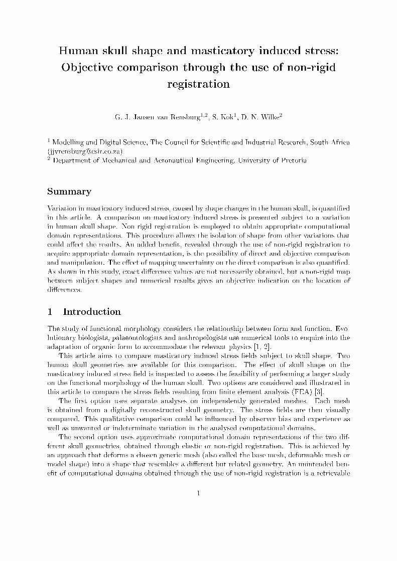
Figure 2: Von Mises stress contours for a molar bite for the range [0, 8]MPa on the (a) prognathicand (b) orthognathic skull shape using meshes independently generated on the edited surfacerepresentation.
of this, the skulls are not fully reconstructed. The initial di�erence in topology between the skullrepresentations is therefore still largely maintained.
Tetrahedral �nite element domains are created from the edited surface representations. Bound-ary conditions are set up for the prognathic and orthognathic representations with the forcedirections and magnitudes approximated and determined using the geometry itself and varioussimilar studies as a guideline [2, 5, 6]. Isotropic linear elastic material properties are used witha Youngâs modulus of E = 16 GPa and Poisson's ratio of ν = 0.3 [7�12]. The prognathic com-putational domain consists of 113 104 nodes and 401 455 elements, whereas the orthognathiccomputational domain is represented by 110 645 nodes and 397 354 elements.
Muscles included in the analysis are the temporalis, medial pterygoid, super�cial masseterand deep head masseter. The fan-like temporalis muscle is approximated by seven segments.All muscle and muscle segment forces are applied at the nodes that approximately representthe muscle attachment location on the skull. These forces act in the approximate direction ofattachment to the mandible, which was determined with the assistance of a medical expert. Thismeans that the force directions are separately determined for the prognathic and orthognathicskull models. For a detailed outline of how the �nite element model is set up, refer to [13].
Figure 2 shows the von Mises stress �eld results on the independently generated computa-tional domains for a molar bite analysis. There is a perceived di�erence in stress �eld that couldindeed be attributed to the di�erence in skull shape. The stress �eld comparison can only becarried out visually or directly compared at speci�c locations. The latter requires the consistentmanual selection of corresponding points in each domain.
It is however possible that the di�erence in the reported stress �eld is not only attributed toa di�erence in skull shape. The comparison may also be sensitive to the relative di�erence inscale, asymmetry of the skulls analysed and topological variation. Topological variation betweenvarious skull geometries may re�ect a true variation in areas such as the sinuses or possibly otherinternal membranes. It is also possible that varying degrees of decay in certain areas may resultin topological inconsistencies where in fact there is none.
The digitally reconstructed prognathic and orthognathic skull shapes are visible in Figures 3and 4. Side views are presented in Figure 3(b) and (d) to give an indication of the relative degreeof prognathism, whereas the translucent �gures presented in Figure 3(a) and (c) also allow thereader to view some of the di�erences in topology. In Figure 4, cuts made with a plane through
3

(a) (b) (c) (d)
Figure 3: The surface mesh representations of the prognathic and orthognathic skull subjects.(a) and (c) are translucent frontal views of the surface representations to illustrate the variationin sinus size and shape. The side views in (b) and (d) contain lines used for the location of thecuts made in Figure 4.
the same approximate location of the two surfaces complement the views in Figure 3 in a furtherattempt to illustrate these di�erences.
In this study, it is required to test the variation in stress �eld because of a di�erence inshape only. With the geometries available for analysis, this could be partly achieved by edit-ing the domains to re�ect the exact same topology. In the remainder of this article, the useof non-rigid registration to obtain approximately symmetric and topologically consistent do-main representations of each skull is illustrated. This is undertaken to inspect the variation inmasticatory-induced stress �eld because of a di�erence in shape only.
3 Non-rigid registration
The elastic surface registration procedure of Moshfeghi et al. [14], as implemented and improvedby Bryan et al. [15], is used as foundation. Bryan et al. [15] used the procedure to analyse theperformance of orthopaedic implants while accounting for inter-patient variability with respectto bone quality and geometry. In [15], their procedure is used to create a three dimensionalmodel of a femur that is ready for statistical analysis and FEA. Bryan et al. [15] registered 46femur geometries and then statistically determined the modes of variation in both shape andmaterial density.
For the work performed in this study, the generic skull shape used as the deformable surfacemesh is created from the digital prognathic skull. The prognathic surface mesh is edited by �llingthe holes caused by decay and the incisions made postmortem to remove the brain. As in theindependent mesh generation case, only small holes were �lled intuitively without the assistanceof a medical expert. The choice of the prognathic skull for the generic mesh generation is basedmainly on the presence of dentition and less decay in the facial area, as compared with theorthognathic skull.
The available registration procedure, implemented from the work of Bryan et al. [15], wasdeveloped for objects of varying shape, but with identical topology. Using our implementation,misrepresentation and self intersection of the deformable surface occurs in areas where featuresand structures are present that are not common to both surfaces but are nevertheless allowedto be registered. A di�erence in topology, as well as overlapping and unmatched features, playa role in invalid registration and subsequent mesh deformation.
4

(a) (b) (c)
(d) (e) (f)
Figure 4: Cut planes made in an attempt to illustrate varying topology. (a)�(c) are intersectionsof the prognathic surface with the planes illustrated in Figure 3(b) with (d)�(f) the approximateequivalent on the orthognathic shape in Figure 3(d).
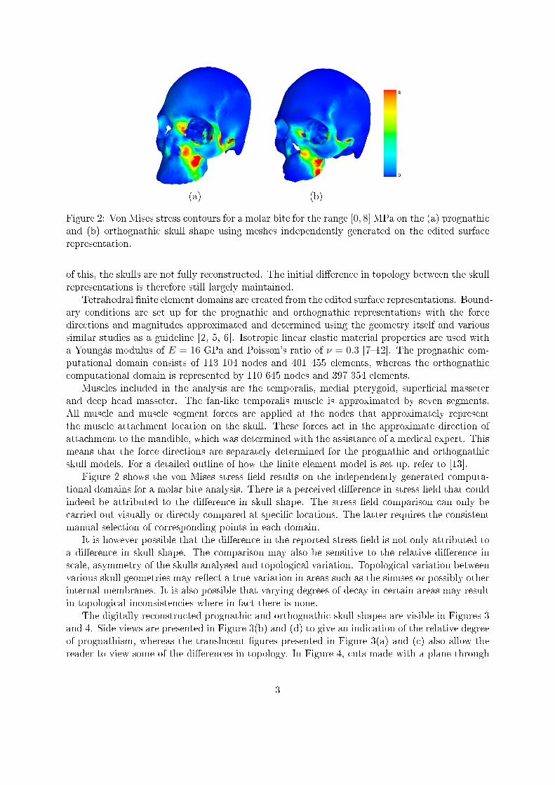
In Figure 5, full elastic surface registration performed on the orthognathic skull is visible.A large part of the target representation in Figure 5(c) seems to have undergone satisfactoryregistration to represent the orthognathic surface. Problems do however occur with surfacenoise, particularly visible internally and in the area of the sinuses.
These problems appear to arise from the topological inconsistencies when the generic andtarget shapes are compared. Because the registration procedure and the ideal stress �eld com-parison require topological consistency, the topology of the generic representation is required tobe �xed and consistent on all domains.
To use the available non-rigid registration procedure, a few constraints are required to en-sure that topological inconsistencies do not play a role in inadequate or undesired registration.Alternatively, the target geometry could be edited to re�ect the same topology as the genericshape, prior to non-rigid registration. The option to constrain the registration procedure ratherthan edit the target is chosen because a study using a larger sample of geometries should thenrequire less user intervention.
The modi�ed registration procedure, that is outlined in this section, consists of three dis-tinguishable steps. Rigid registration is �rst performed to rotate, scale and translate the targetshape in such a way that it is globally aligned to the deformable generic mesh. Curvature infor-mation is then used to extract feature information. Features on the generic and target shapesare compared and areas in the vicinity of mismatched features are classi�ed as low con�dencesurface areas. Constrained nonrigid surface registration is subsequently performed using onlyhigher con�dence areas to deform the generic domain. The elastic surface registration procedureis presented in Appendix A of this article for easy reference. For further detail into the procedure,the reader is referred to the appendix of the article by Bryan et al. [15].
5
(a) (b) (c)
Figure 5: (a) Deformable model at iteration 0. (b) Deformable model at iteration 60 in blueoverlayed on the pink orthognathic target surface. (c) Deformable model at iteration 60. Thesame registration procedure parameters are used as Bryan et al. [15].
3.1 Rigid registration
Before deforming the generic skull shape into a representation of the target skull form, an a�neregistration is performed using an iterative closest point (ICP) method. Besl and McKay [16]approached the problem of obtaining a rigid transformation in point set registration in a leastsquares manner. Later versions of their method also attempt anisotropic scaling in additionto rotation and translation. One such method proposed by Du et al. [17] uses an iterativea�ne transformation implemented through the use of rotation, re�ection and anisotropic scalingmatrices with a translation.
The procedure of Du et al. [17] is used in this report to align a target shape with thedeformable surface mesh prior to elastic surface matching and mesh morphing. Isotropic scalingis achieved with their procedure by including a modi�cation that only allows a single scalevariable during optimisation, instead of the three variables used in [17].
3.2 The use of curvature information
In this study, it is required to compare the stress in representative domains that have no di�erencein topology and scale. Because non-rigid registration is used to obtain the representative domainsin this study, it would be preferable to only use the attributes associated with facial form to informthe deformation of the generic mesh. This is undertaken so that a noticed variation in stress�eld may be more likely as a result of the facial attributes, rather than the undesired possibilitythat a variation caused by topology or some other unmatched feature is reported.
To use the available non-rigid surface registration procedure, without the need to �rst edit atar- get shape, registration constraints are determined using feature and curvature information.Feature lines are �rst extracted using the method proposed by Kim and Kim [18]. This methodinvolves the approximation of an implicit surface at each point to extract curvature information.The principal curvatures and their derivatives are then used to connect possible feature pointsinto lines.
Decayed areas were simply removed from the generic representation, therefore, the genericmesh used in this study is not representative of a fully reconstructed skull. Most of the featuresinternal to the facial region of the generic representation are therefore arti�cial. The sinusesalong with other arti�cial ridge and valley features of the internal facial area of the generic
6

(a) (b)
Figure 6: (a) User selected allowable feature lines on the model skull geometry. (b) The registeredposition of the model features and corresponding feature lines extracted on the orthognathictarget geometry.
skull are removed from the allowable feature lines and surfaces in this study. This leaves mainlyexternal features that allows the capture of overall shape of each skull, as is visible in Figure 6(a).Areas associated with these higher con�dence features and salient areas on the generic shape areallowed to register during elastic surface matching and mesh morphing.
Using the allowable feature lines on the generic shape, feature line registration is performedto automatically detect corresponding higher con�dence feature areas on a target prior to non-rigid surface registration. Feature line registration is performed with a procedure similar to thatproposed by Subsol et al. [19]. In our implementation, the point correspondence and registrationcorrection is carried out in the same way as explained by Subsol et al. [19].
In the procedure of Subsol et al. [19], three transformations are used during registration: arigid transformation �rst aligns the sets of lines after which a�ne transformations retrieve thescalar di�erences between the sets. Spline transformations are �nally used to determine andperform local deformation. In our procedure, the feature line registration is integrated into thenon-rigid surface registration procedure. This means that the scale and orientation correction iscarried out before the feature registration step. Using the elastic surface registration procedureoutlined in Appendix A, it was decided that the local deformation would be performed iteratively,using the deformation calculation of the procedure instead of the spline transformation used bySubsol et al. [19].
Registration of the allowable feature lines on the generic skull to the orthognathic form isdisplayed in Figure 6(b). In this �gure, the location of the deformed lines after registration tothe orthognathic form is visible as the blue lines. The corresponding features registered on thetarget geometry is displayed using red lines. The unregistered features on the target surface arediscarded and not depicted.
Registration to the high curvature surface areas associated with unmatched features areclassi�ed as untrusted and are automatically discarded. Points in high curvature areas areclassi�ed using the magnitudes of principal curvature information gathered during feature line
7

(a) (b) (c)
Figure 7: Mesh points on areas within the bounds of user selected curvature. (a) High curvatureareas on the orthognathic skull target geometry. (b) High curvature areas corresponding to theuser selected allowable feature lines seen in Figure 6(a). (c) The automatically selected allowablefeature areas obtained after the feature registration on the orthognathic target geometry seen inFigure 6(b).
extraction.Feature points satisfying the user speci�ed curvature conditions on the orthognathic mesh are
illustrated in Figure 7(a). The skulls have been scaled during the a�ne ICP procedure, so therelative scale di�erence in the curvature of corresponding features is assumed to be negligible.The length scale in this case is millimetres and curvatures are approximated at each vertex on thesurface using neighbour vertices within a spherical radius of 5 mm to approximate the implicitsurface. Only points with principal curvature values κmin ≤ −0.18 mm−1 or κmax ≥ 0.18 mm−1
are displayed and considered as part of high curvature feature areas in this study. Figure 7(b)contains points with high curvature on the generic mesh that correspond to the user selectedallowable feature lines displayed in Figure 6(a). After feature registration, the higher con�dencefeature areas on the target can be obtained by computing its relative distance to feature lines.If the closest feature line to a point is an unmatched line, then this point and the triangles thatcontain it are classi�ed as part of an unmatched feature. Feature points on the orthognathic shapethat are automatically classi�ed as part of higher con�dence features are visible in Figure 7(c).
The use of curvature information to inform and constrain the allowable surface registrationareas is included in the procedure to reduce the amount of user intervention required. Theselection of allowable features is performed once o� on the generic mesh, without the requirementto edit the target in such a way as to obtain the same topology as the deformable genericshape. Should the procedure be implemented to retrieve approximate representations of a largerstatistical sample of skull geometries, the inclusion of this step would translate into overall lessuser intervention.
3.3 Computational domain preparation
After excluding the areas where a mismatch in features could result in undesired registration, non-rigid surface registration is performed using the procedure of Bryan et al. [15]. The topology of thegeneric skull is now maintained although only deforming the domain to capture the overall shapeand attributes of the prognathic and orthognathic shape. In their study, Bryan et al. [15] used a
8

(a) (b)
Figure 8: Approximate symmetric versions of the (a) prognathic and (b) orthognathic skullgeometries.
nearest neighbour parameter n = 50, the smoothing parameters γ = 2, σ0 = 10 and f = 1.0715and the maximum iterations kmax was set to 100 when registering the femur geometries. Thesame parameters are used here to register and deform the generic skull mesh.
For this study, a tetrahedral element mesh is generated on the generic triangular surface mesh.The tetrahedral mesh is deformed using the Gaussian weighting function implemented into theregistration procedure. To make the elastic surface registration more robust, the deformationobtained as a result of the Gaussian function is smoothed using Taubin smoothing [20]. Thissmoothing acts as a low-pass �lter to reduce unwanted high frequency deformation, makingthe inversion of elements less likely. A broad overview of the implemented Taubin smoothingprocedure is presented in Appendix B.
Both prognathic and orthognathic skull geometries are registered and approximately repre-sented by a deformed generic mesh. The target shapes are the original surfaces visible in Figure 3.The procedure for matching feature lines and determining lower con�dence registrations is ap-plied to both models, and the generic surface is deformed into target representations. The targetgeometries are left totally unedited with all the user speci�ed constraints and restrictions onlyapplied to the generic deformable mesh.
The generic model is deformed into a target shape as well as the re�ected target shape.The average of the two deformed meshes is then used to create a symmetric version of thetarget. The near symmetric versions of both the orthognathic and prognathic skull geometriesare illustrated in Figure 8. The stress �elds in these symmetric representations are compared inthe next section, to remove the e�ect of asymmetry. The cut planes shown in Figure 9 are of thesymmetric domain representations. These cut planes are at the same approximate locations asthe cut planes presented in Figure 4 of the original skull representations.
Because there is now a consistent mapping between the symmetric prognathic and orthog-nathic shapes, a mesognathic skull can now be created by averaging the nodal coordinates ofthese representations. A high quality tetrahedral mesh is then generated using this mesognathicskull surface. This is carried out so that the tetrahedral mesh would not result in a bias towardthe prognathic skull during analysis. This domain is then deformed back into the prognathicand orthognathic skull representations using the known surface displacements. These knownboundaries are used in linear elastic �nite element analyses to determine the displacements of
9
(a) (b) (c)
(d) (e) (f)
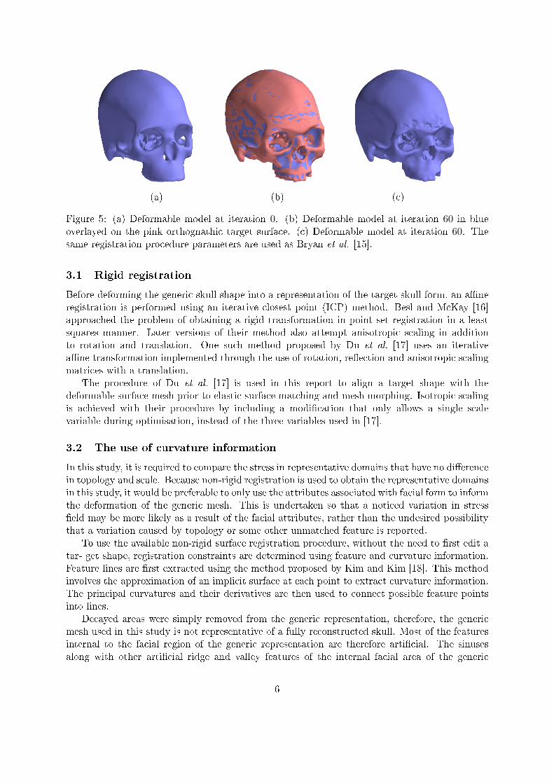
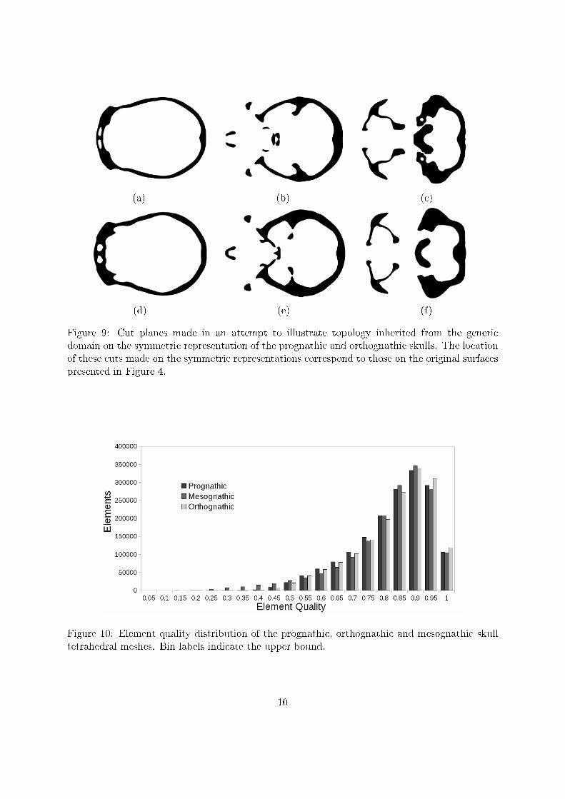
Figure 9: Cut planes made in an attempt to illustrate topology inherited from the genericdomain on the symmetric representation of the prognathic and orthognathic skulls. The locationof these cuts made on the symmetric representations correspond to those on the original surfacespresented in Figure 4.
Figure 10: Element quality distribution of the prognathic, orthognathic and mesognathic skulltetrahedral meshes. Bin labels indicate the upper bound.
10

internal nodes. The full nodal displacements are then applied to the mesognathic tetrahedralmesh to obtain the prognathic and orthognathic meshes.
The boundary coordinates of the tetrahedral mesh is constrained during mesh untanglingand optimisation. This step is performed with the MESQUITE (MESQUITE Software, Inc,Austin, TX, USA) [21] mesh quality improvement toolkit. A histogram illustrating the elementquality distribution of the prognathic, mesognathic and orthognathic tetrahedral meshes afteroptimisation is visible in Figure 10. A brief overview of MESQUITE and further details on theelement quality metric is given in Appendix C. From the element quality distribution in Figure 10there seems to be no bias toward either prognathic or orthognathic mesh representation.
4 Comparing masticatory induced stress
The three tetrahedral meshes representing prognathic, mesognathic and orthognathic form areanalysed for an applied molar bite force. The nodes, where boundary conditions are applied,are the exact same nodes for all three domain representations. All three meshes consist of 290569 nodes and 1 687 791 elements. A �ner mesh is used than those independently analysed.This is done in the hope that the elements are more likely to maintain good quality during meshdeformation. The boundary conditions and material properties are handled in the same way asdiscussed in Section 2. The direction of the muscle forces for the mesognathic case is obtainedby interpolating between the known directions in the prognathic and orthognathic cases. If themodels included mandibles, muscle force direction would be determined completely by using thenode numbers that represent the attachment location on the mandible for that muscle.
In Figure 11, the Von Mises stresses are given with all stresses higher than 8 MPa simplyshown in red. The maximum resulting Von Mises stress for the analyses are 18.56 MPa forthe prognathic skull form, 15.334 MPa on the mesognathic skull form and 17.589 MPa for theorthognathic skull form respectively.
If the requirement is simply to analyse the appropriate domains obtained by non-rigid regis-tration, these results may be compared in the same way as the independently meshed results inFigure 2. Figures 11(a) and (c) compare well with the results displayed in Figures 2(a) and (b).The di�erence in stress �eld visible between the prognathic and orthognathic shapes in Figure 11is no longer a�ected by asymmetry and topological variation, whereas the results displayed forcomparison in Figure 2 do implicitly contain these e�ects. Because a target geometry is isotrop-ically scaled to the generic mesh in the ICP alignment, it may also be assumed that the e�ect ofscale on the variation in stress �eld is negligible.
To illustrate the unintended bene�t of obtaining appropriate domain representations by non-rigid registration, the results of the FEA are manipulated using this one to one domain corre-spondence already available. In Figure 12, resulting von Mises stress �elds in the prognathic andorthognathic forms are compared. Here, the von Mises stresses in the orthognathic skull domainand prognathic skull domain are displayed at the approximate location of those elements on themesognathic domain representation.
The results are compared in Figure 12(c) by taking the di�erence in von Mises stress. Thedi�erence in the Cauchy stress tensor for instance is not an accurate representation of the actualdi�erence in stress. Stress tensors are recovered from a FEA on di�erent geometries with the samemesh topology. For each mesh, the same element is likely to have a di�erent global orientation.A proper interpolation scheme is therefore required or one may compare invariants of the stresstensor such as the eigenvalues (principal stresses). Von Mises stress is used in this examplebecause it is also rotationally invariant.
11

(a) (b) (c)
Figure 11: Von Mises stress contours for a molar bite for the range [0, 8] MPa on the (a) prog-nathic, (b) mesognathic and (c) orthognathic skull shape.
(a) (b) (c)
Figure 12: Von Mises stress contours for a molar bite for the range [0, 8]MPa of the (a) prognathicand (b) orthognathic skull shape plotted on the mesognathic skull shape. (c) The contours of
di�erence in Von Mises stress between the analysed shapes(σvMprognathic − σvMorthognathic
)for the
range [−8, 8] MPa on the mesognathic skull shape.
12

From the variation in masticatory induced stress �eld presented in Figure 12(c), it wouldappear from this analysis that there is a higher stress in the zygomatic arch and bridge of thenose in the prognathic skull form, while the orthognathic form has a higher stress concentrationin the maxilla or upper mandible. This report does not however aim to draw conclusions betweenprognathism and stress. This report merely inspects the use of non-rigid registration in such astudy. Before a claim can be made on the e�ect of prognathism and stress, a detailed studyis required. This detailed study would require a larger number of skulls, modelled with higherdetail and combined with a statistical analysis. A study on prognathismâs e�ect on masticatoryinduced stress would also require greater input from an anthropologist or some other interestedmedical professional to set up models and draw conclusions.
4.1 The e�ect of mapping uncertainty
If the non-rigid registration procedure is merely used as a means to extract an appropriatedomain representation, a possible uncertainty in the non-rigid map between domains wouldpresent no concern. In this study however, the mapping is also used to make objective and directcomparisons. It would be undesirable to assign signi�cance to a speci�c variation in stress orsome other quantity owing to some uncertainty in the accuracy of the mapping. Note that thismapping uncertainty is inherently part of this type of problem and not caused by some limitationof the chosen elastic registration procedure. When mapping one skull form to another, an exactsolution does not exist, and any registration procedure merely attempts to provide some realisticmapping.
Various meshes representing the orthognathic skull geometry are created in an attempt to il-lustrate and quantify the e�ect of registration uncertainty and discretisation on the FEA resultsand subsequent comparison. The non-rigid registration procedure used in this speci�c studyrequires user de�ned registration and smoothing parameters. Two additional meshes are gen-erated using the symmetric orthognathic skull as the target during non-rigid registration. Theregistration is performed using two sets of smoothing parameters:
� γ = 2, σ0 = 10 and f = 1.0715 and
� γ = 2, σ0 = 20 and f = 1.0715.
The original surface mesh representing the symmetric orthognathic skull shape along with theresult obtained from the two additional registrations are visible in Figure 13. Figure 13(a) showsthat the three meshes represent the same geometry, whereas the detail of Figure 13(b) showsthat there is not an exact solution.
The tetrahedral mesh, generated on the mesognathic surface mesh is deformed using thedisplacement of boundary nodes and again optimised using MESQUITE [21].
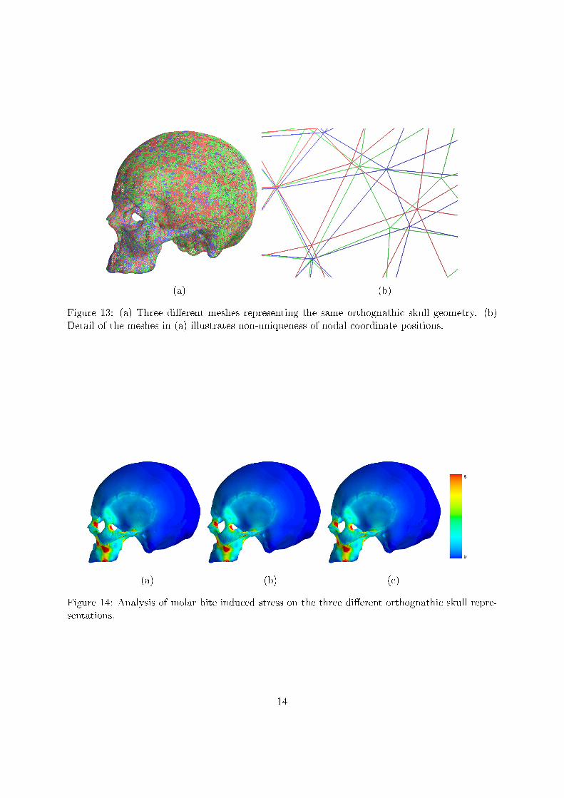
When referring to the prognathic mesh, the symbol P1 is used. O1 is the original orthognathicmesh with O2 and O3 as the two additional meshes generated to represent the orthognathic skullform. The von Mises stresses of the results of a molar bite simulation on the three orthognathicmeshes are given in Figure 14. Figure 14(a) is a side view of the original analysis also displayedin Figure 11(c). Along with this result, the von Mises stress on the other two meshes representingthe orthognathic form are displayed in Figures 14(b) and (c). From this �gure, it is visible thatessentially the same analysis is performed.
The results of the three orthognathic meshes are compared with the result on the prognathicmesh in the same way as in Figure 12(c). With a slightly di�erent mapping between the prog-
13
(a) (b)
Figure 13: (a) Three di�erent meshes representing the same orthognathic skull geometry. (b)Detail of the meshes in (a) illustrates non-uniqueness of nodal coordinate positions.
(a) (b) (c)
Figure 14: Analysis of molar bite induced stress on the three di�erent orthognathic skull repre-sentations.
14

(a) (b) (c)
Figure 15: The di�erence in Von Mises stress for various combinations of the prognathic andorthognathic molar bite analyses. Contours are given for the range [−2, 2] MPa. The calculated
range is (a) [=7.978, 12.839] MPa for(σvMP1 − σvMO1
), (b) [=7.171, 12.332] MPa for
(σvMP1 − σvMO2
)and (c) [=7.584, 12.232] MPa for
(σvMP1 − σvMO3
)respectively.
(a) (b) (c) (d)
Figure 16: (a) Average of the three comparisons. (b)�(d) Deviation of the three direct compar-isons from the average.
nathic and each orthognathic shape, the di�erence in von Mises stress �eld varies as depicted inFigure 15.
Figure 15(a) is the same results as illustrated in Figure 12(c) but shows contours for σvMP1 −σvMO1in the range [−2, 2] MPa. Figures 15(a), (b) and (c) are generated by comparing the sameprognathic mesh result (σvMP1 ) with the three di�erent orthognathic mesh results (σvMO1 , σ
vMO2 and
σvMO3 ).Figure 15 only shows contours of the di�erence in Von Mises stress for the range [−2, 2] MPa,
with the true range interval for each comparison given in the �gure caption. Slight variation isnoted in the di�erence in Von Mises stress between the prognathic and orthognathic shape whencomparing these results.
In this case, although a slight variation in stress �eld pattern is visible in Figure 15, theoverall di�erence in stress �eld between the two skull forms analysed may likely be attributed tothe di�erence in form and not to the uniqueness of the mapping used between them.
The variation in di�erence in von Mises stress is inspected in Figure 16. The average of theresults in Figure 15 is used as a baseline, and it is depicted in Figure 16(a). Figures 16(b) to (d)are the deviations of the original comparisons from the baseline.
From these results, it seems that although the analyses on the di�erent orthognathic represen-
15

tations are similar, the variation in how one geometry is mapped to the other does a�ect the com-parison. In this particular study, the e�ect of mapping uncertainty only contributes marginallyto the stress variation result. The use of non-rigid registration to obtain computational domainrepresentations allows the opportunity to at least approximately evaluate dissimilarity in stress�eld because of shape in this objective and direct manner.
5 Discussion
From the results presented in Section 3, it seems that a study on the e�ect of only shape onstress results performed with the use of non-rigid registration is feasible. The use of numericaltechniques such as the one discussed in this article allows the isolation of shape from othervariations that could a�ect the results. An added bene�t revealed through the use of non-rigid registration to acquire appropriate domain representation is the possibility of direct andobjective comparison and manipulation. If direct comparison or statistics is carried out usingthe consistent domain representations, it is however important to inspect and quantify the e�ectof the direct mapping uncertainty.
Deforming one human skull domain or a representative human skull domain to better repre-sent another has no true equivalent in nature and cannot be determined or veri�ed experimentally.In a study of this type, where comparison is undertaken using non-rigid registration, it is onlypossible to compare distinguishable landmark locations and force these to map exactly. Thechallenge lies in obtaining an accurate map between other discretised and speci�cally feature-less areas where there is no known exact solution to the mapping. For this reason, a simplequanti�cation of uncertainty in the mapping is also presented along with the direct comparison.
The various direct comparisons presented illustrates that the di�erence in stress �eld displayedin this manner is slightly a�ected by the non-rigid mapping. The e�ect of a di�erence in shapeis however orders of magnitude bigger than the e�ect of mapping uncertainty in the resultspresented. The use of non-rigid registration as a direct and objective comparison technique isa viable option to at least determine and visualise the approximate areas where a di�erence instress �eld may be observed.
In further work, a more detailed generic skull model should be reconstructed. Conclusionson the e�ect of skull shape on stress �eld should also be drawn with the assistance of a medicalprofessional. If a larger statistical sample of skull geometries are used and analysed with aconsistent mapping between them, principal components of shape or modes of deformation andstress could be extracted with relative con�dence. The di�erence in stress or displacementfrom the mean stress and deformation caused by some mode of variation could then be betterapproximated and illustrated.
Appendix A: Non-rigid surface registration
Two meshes are taken as an input with M the generic and P the target surface. These twosurface meshes consist of point data and connectivity lists de�ning the triangle patches thatde�nes the surface. The generic surface is deformed iteratively to better represent the targetwithout a�ecting connectivity. This is done as follows:
� Registration inputs are speci�ed. These include the target mesh P and base mesh M.Other user speci�ed parameters are a nearest neighbour parameter n, smoothing param-eters γ, σ0 and f , maximum number of iterations kmax and stopping criteria tolerance
16

εT .
� Rigid registration is performed to align the target geometry to the generic mesh using anICP procedure.
� The iteration counter and deformable surface is initialised so that k = 1 and W0 = M.Registration is performed while k ≤ kmax or until the convergence criteria is met:
� Four k − d tree representations are constructed. This is done for the centroids ofsurface triangulations and nodal coordinates of both Wk−1 and P.
� For each node wj in Wk−1, j ∈ {1, 2, ..., Nm}, a registration to the target surfaceis determined. The n nearest target triangles to wj and registration points on theseclosest triangles are determined. The point rwj is produced by drawing a line from thepoint wj perpendicular to the plane of each registered triangle. A distance measureis then assigned to the triangles. If the registered point rwj lies inside a triangle, the
distance measure is computed as∣∣∣rwj −wj
∣∣∣. Alternatively, if the point lies outside atriangle the distance measure is computed as
∣∣∣rwj −wj
∣∣∣ + ∣∣∣pwj − rwj
∣∣∣, where pwj is
the closest vertex of that triangle to point wj . Inspecting all the distance measures,the closest triangle to point wj and the registration associated with it is obtained. Ifthe point rwj lies inside the closest triangle, the displacement is calculated as dwj =rwj − wj . Alternatively, if the point lies outside the triangle the displacement iscalculated as dwj = pwj −wj .
� This registration procedure is then done again for P onto Wk−1. For each node piin P, i ∈ {1, 2, ..., Np}, a displacement to the deformable surface is determined asdpi = rpi − pi if the point rpi lies inside the closest triangle or dpi = mpi − pi if thepoint rpi lies outside the closest triangle.
� Having registered Wk−1 onto P and P onto Wk−1, a smooth displacement �eld iscomputed for a point x as
Sk−1 (x) =1
γ
[∑Nmj=1G (‖x−wj‖)dwj∑Nmj=1G (‖x−wj‖)
−∑Nmj=1G (‖x− rpi‖)dpi∑Nmj=1G (‖x− rpi‖)
]. (2)
In Equation (2), G (d) is the Gaussian weighting function suggested by Moshfeghi[14]:
G (d) = e−d/σ2k , (3)
where d is a positive scalar distance measure. The smoothing parameter σk is de-creased at each iteration allowing for more compact support using the update σk =σ0f
−k with 1 ≤ f ≤ 2.
� The deformable surface is updated as
Wkj =Wk−1
j + Sk−1 (wj) . (4)
� To prevent mesh folding, Bryan et al. [15] performed a set number of improved Lapla-cian smoothing iterations to the deformable mesh Wk
j before performing another reg-istration iteration. In our work, ten Taubin smoothing [20] operations are performedevery �ve elastic surface registration iterations. This type of smoothing is chosen forit's ability to reduce high frequency surface noise without the high loss of volumeassociated with Laplacian smoothing.
17

� Convergence is determined on the average total deformation as applied at the currentiteration. The solution is terminated if
ε =1
Nm
Nm∑j=1
∣∣∣Sk−1 (wj)∣∣∣ ≤ εT . (5)
The updated nodal coordinates of the generic mesh is returned after reaching a stop-ping criterion. This stopping criterion is either the satisfaction of Equation (5), themaximum number of iterations reached or no further improvement on the error valueε.
Appendix B: Taubin smoothing
Taubin smoothing extends signal processing to signals de�ned on polyhedral surfaces of arbitrarytopology, reducing the problem of surface smoothing to a low-pass �lter problem [20]. The lowfrequency content of the signal is regarded as subjacent data while the high frequency contentis seen as noise. In this smoothing procedure, Fourier analysis is extended to signals de�ned onpolyhedral surfaces based on the observation that the classical Fourier transform decomposes asignal into a linear combination of the eigenvectors of the Laplacian operator. A new operatoris de�ned to take the place of the Laplacian.
Consider a polygonal curve or surface represented as a list of consecutive vertices xi, i ∈{1, 2, ..., N} with the neighbouring vertices of each point i given in the connectivity informationi?. If a discrete surface signal is a function φ = {φ1, φ2, ..., φN}, the discrete Laplacian of thediscrete surface signal by weighted averages over the neighbourhoods may be de�ned as
Li =1∑
j∈i? ωij
∑j∈i?
ωij (φj − φi) . (6)
The weights ωij are positive numbers, with the simplest choice ωij = 1. Taubin [20] proposedthe use of alternate scale factors of opposite sign λ and µ with λ+ µ < 0, 0 < λ < 1 such that avertex coordinate update may be determined iteratively by
xi ← xi + λLixi ← xi + µLi. (7)
The implementation in this article used λ = 0.5 and µ = −0.53.
Appendix C: Usable mesh generation
The MESQUITE mesh quality improvement toolbox is used to untangle and optimise the tetra-hedral meshes in this article. The toolbox consists of libraries and header �les providing an arrayof quality metrics, objective function assembly templates and quality improvement algorithmswritten in C++.
The mean ratio quality metric is used for element shape optimisation in this article and maybe constructed analytically [22]. If Q is a n × n matrix with det (Q) > 0, the mean ratio of Qis the scalar
qµ =n det (Q)2/n
‖Q‖2F, (8)
18

with ‖Q‖2F the Frobenius norm of the matrix. In this article, tetrahedral elements are used andso the quality is evaluated with respect to an equilateral tetrahedron with all of it's edges unitlength. If J is the Jacobian matrix referenced to node x0 on a particular element of concern andW is the Jacobian matrix referenced to node x0 of the equilateral tetrahedron, Q = JW−1 isthe 3 × 3 Jacobian matrix of the a�ne transformation that maps the element to the referenceshape. This quality metric is used in the article and is the metric used to show the quality ofthe meshes in Figure 10.
Acknowledgements
We acknowledge the assistance of M.L. Mac Kay and Prof. M. Steyn from the AnthropologyDepartment of the University of Pretoria and thank the Department of Anatomy of the Univer-sity of Pretoria for making their skull collection available for this study. We also acknowledgeLabuschagne and partners at the Little Company of Mary Hospital for producing the CT scansused in reconstructing digital surface representations of the skulls.
References
[1] Panagiotopoulo O. Finite element analysis (FEA): applying an engineering method to func-tional morphology in anthropology and human biology. Annals of Human Biology 2009;36(5):609�623.
[2] Richmond B, Wright B, Grosse I, Dechow P, Callum F, Spencer M, Strait D. Finite elementanalysis in functional morphology. The Anatomical Record Part A 2005; 283A:259�274.
[3] Cook R, Malkus D, Plesha M, Witt R. Concepts and applications of Finite Element Analysis.John Wiley & Sons: New York, 2002.
[4] Robertson J. More on skeletal analysis and the race concept. Current Anthropology 1979;20(3):617.
[5] Blanksma N, van Eijden T. Electromographic heterogeneity in the human temporalis muscle.Journal of Dental Research 1990; 69:1686�1690.
[6] Strait D, Richmond B, Spencer M, Callum F, Dechow P, Wood B. Masticatory biometricsand its relevance to early hominid phylogeny: An examination of palatal thickness using�nite-element analysis. Journal of Human Evolution 2007; 52:585�599.
[7] Boryor A, Geiger M, Hohmann A, Wunderlich A, Sander C, Sander F, Sander F. Stress distri-bution and displacement analysis during an intermaxillary disjunction - a three-dimensionalFEM study of a human skull. Journal of Biomechanics 2008; 41:376�382.
[8] Camacho D, Hopper R, Lin G, Myers B. An improved method for �nite element meshgeneration of geometrically complex structures with application to the skullbase. Journal ofBiomechanics 1997; 30:1067�1070.
[9] Groning F, Liu J, Fagan M, O'Higgins P. Validating a voxel based �nite element model of ahuman mandible using digital speckle patter interferometry. Journal of Biomechanics 2009;42:1224�1229.
19

[10] Ichim I, Sawin M, Kieser J. Mandibular biomechanics and development of the human chin.Journal of Dental Research 2006; 85:638�642.
[11] Kupczik K, Dobson C, Fagan M, Crompton R, Oxnard C, O'Higgins P. Assessing mechanicalfunction of the zygomatic region in macaques: validation and sensitivity testing of �niteelement models. Journal of Anatomy 2007; 210:41�53.
[12] Tanne K, Miyasaka J, Yamagata Y, Sachdeva R, Tsutsumi S. Three-dimensional modelof the human craniofacial skeleton: method and preliminary results using �nite elementanalysis. Journal of Biomedical Engineering 1988; 10:246�252.
[13] Jansen van Rensburg G. Selective feature preserved elastic surface registration in complexgeometric morphology.Master's Thesis, University of Pretoria, South Africa 2011. (Availablefrom: http://upetd.up.ac.za/UPeTD.htm).
[14] Moshfeghi M, Ranganath S, Nawyn K. Three-dimensional elastic matching of volumes. IEEETransactions on Image Processing 1994; 3(2):128�138.
[15] Bryan R, Mohan P, Hopkins A, Galloway F, Taylor M, Nair P. Statistical modelling of thewhole human femur incorporating geometric and material properties. Mechanical Engineer-
ing and Physics 2010; 32:57�65.
[16] Besl P, McKay H. A method for registration of 3-D shapes. IEEE Transactions on Pattern
Analysis and Machine Intelligence 1992; 14:239�256.
[17] Du S, Zheng N, Ying S, Liu J. A�ne iterative closest point algorithm for point sets regis-tration. Pattern Recognition Letters 2010; 31:791�799.
[18] Kim S, Kim C. Finding ridges and valleys in a discrete surface using a modi�ed MLSapproximation. Computer Aided Design 2006; 38:173�180.
[19] Subsol G, Thirion J, Ayache N. A general scheme for automatically building 3D morphome-tric anatomical atlasses: application to a skull atlas. Medical Image Analysis 1998; 2:37�60.
[20] Taubin G. A signal processing approach to fair surface design. Proceedings of the 22nd
Annual Conference on Computer Graphics and Interactive Techniques, Los Angeles, 1995;351�358.
[21] Mesquite. (Available from: http://www.cs.sandia.gov/optimization/knupp/Mesquite.html).
[22] Escobar J, Rodrigues E, Montenegro R, Montero G, Gonzalez-Yuste J. Simultaneous untan-gling and smoothing of tetrahedral meshes. Computer Methods in Applied Mechanics and
Engineering 2003; 192:2775�2787.
20