hp storageworks disk system 2100 / 2110 user’s guide · hp storageworks disk system 2100 / 2110...
TRANSCRIPT
HP StorageWorks Disk System 2100 / 2110
User’s Guide
Edition E0304
Order No. A7381-96013
Printed in U.S.A.

Notice© Hewlett-Packard Company, 2004. All rights reserved.
Hewlett-Packard Company makes no warranty of any kind with regard to this document, including, but not limited to, the implied warranties of merchant-ability and fitness for a particular purpose. Hewlett-Packard shall not be liable for errors contained herein or for incidental or consequential damages in connection with the furnishing, performance, or use of this material. This document contains proprietary information, which is protected by copyright. No part of this document may be photocopied, reproduced, or translated into another language without the prior written consent of Hewlett-Packard. The informa-tion contained in this document is subject to change without notice.
Warranty If you have any questions about the warranty for this product, contact your dealer or local Hewlett-Packard sales representative.
Safety Notices
To protect against personal injury and product damage, do not attempt to lift the product without the assistance of another person or lift device.
Components bearing this symbol may be hot to touch.
Components bearing this symbol are fragile. Handle with care.
Components bearing this symbol are susceptible to damage by static electricity. ESD precautions are required.
Operation
The front door should be closed and locked at all times during the operation of this product except when replacing disks.
This product is intended to be operated in a restricted access area.
Service
Maintenance or repair of the backplane and mezzanine boards must be performed by authorized service-trained personnel.
Format Conventions
Denotes
WARNING A hazard that can cause personal injury
A hazard that can cause hardware or software damage
Note Significant concepts or operating instructions
this font Text to be typed verbatim: all commands, path names, and file names. Also menu and button selections in GUI contexts
this font Text displayed on the screen
Weight exceeds 50 lbs. (22.5 kg.)
Do NOT lift unassisted. Usea lift device or two people.
WarningCAUTION
2
3Table of Contents
Overview . . . . . . . . . . . . . . . . . . . . . . . . . . . . . . . . . . . . . . . . . . . . . . . 7Components of the Disk System . . . . . . . . . . . . . . . . . . . . . . . . . . . . . 8
Front Panel . . . . . . . . . . . . . . . . . . . . . . . . . . . . . . . . . . . . . . . . . . . . . . . . . . . . . . . . . . . . . . 8Disk Module LEDs . . . . . . . . . . . . . . . . . . . . . . . . . . . . . . . . . . . . . . . . . . . . . . . . . . . . . . . . 8System Power LED. . . . . . . . . . . . . . . . . . . . . . . . . . . . . . . . . . . . . . . . . . . . . . . . . . . . . . . . 8Rear Panel . . . . . . . . . . . . . . . . . . . . . . . . . . . . . . . . . . . . . . . . . . . . . . . . . . . . . . . . . . . . . . . 9SCSI ID Switch. . . . . . . . . . . . . . . . . . . . . . . . . . . . . . . . . . . . . . . . . . . . . . . . . . . . . . . . . . 10Power Connector. . . . . . . . . . . . . . . . . . . . . . . . . . . . . . . . . . . . . . . . . . . . . . . . . . . . . . . . . 11
Electrical Requirements. . . . . . . . . . . . . . . . . . . . . . . . . . . . . . . . . . . 11AC Site Requirements. . . . . . . . . . . . . . . . . . . . . . . . . . . . . . . . . . . . . . . . . . . . . . . . . . . . . 11
Installing the Disk System . . . . . . . . . . . . . . . . . . . . . . . . . . . . . . . . 12Hardware Requirements . . . . . . . . . . . . . . . . . . . . . . . . . . . . . . . . . . . . . . . . . . . . . . . . . . . 12Preparing for Installation . . . . . . . . . . . . . . . . . . . . . . . . . . . . . . . . . . . . . . . . . . . . . . . . . . 12Setting the SCSI IDs for the Disk Modules . . . . . . . . . . . . . . . . . . . . . . . . . . . . . . . . . . . . 13
Installing the Disk System . . . . . . . . . . . . . . . . . . . . . . . . . . . . . . . . 14Connect the SCSI Cables . . . . . . . . . . . . . . . . . . . . . . . . . . . . . . . . . . . . . . . . . . . . . . . . . . 14Connecting the Power Cable. . . . . . . . . . . . . . . . . . . . . . . . . . . . . . . . . . . . . . . . . . . . . . . . 16
Powering On and Off . . . . . . . . . . . . . . . . . . . . . . . . . . . . . . . . . . . . . 16Power On the Disk System . . . . . . . . . . . . . . . . . . . . . . . . . . . . . . . . . . . . . . . . . . . . . . . . . 16Power Off the Disk System. . . . . . . . . . . . . . . . . . . . . . . . . . . . . . . . . . . . . . . . . . . . . . . . . 17
Adding Disk Modules . . . . . . . . . . . . . . . . . . . . . . . . . . . . . . . . . . . . . 18Add a Disk Module. . . . . . . . . . . . . . . . . . . . . . . . . . . . . . . . . . . . . . . . . . . . . . . . . . . . . . . 18Configure the new Disk Module. . . . . . . . . . . . . . . . . . . . . . . . . . . . . . . . . . . . . . . . . . . . . 19
Remove and Replace A Disk Module . . . . . . . . . . . . . . . . . . . . . . . . . 19Remove a Disk Module . . . . . . . . . . . . . . . . . . . . . . . . . . . . . . . . . . . . . . . . . . . . . . . . . . . 19Replace a Disk Module. . . . . . . . . . . . . . . . . . . . . . . . . . . . . . . . . . . . . . . . . . . . . . . . . . . . 20
Remove the Disk System . . . . . . . . . . . . . . . . . . . . . . . . . . . . . . . . . . 21Setting Up the Hardware Event Monitor (HP-UX Only) . . . . . . . . . . . 22Configuration Overview. . . . . . . . . . . . . . . . . . . . . . . . . . . . . . . . . . . 22
Event Notification (HP-UX Only) . . . . . . . . . . . . . . . . . . . . . . . . . . . . . . . . . . . . . . . . . . . 23Status LEDs . . . . . . . . . . . . . . . . . . . . . . . . . . . . . . . . . . . . . . . . . . . . . . . . . . . . . . . . . . . . 25
View Disk Status . . . . . . . . . . . . . . . . . . . . . . . . . . . . . . . . . . . . . . . 26STM Disk Information: HP-UX . . . . . . . . . . . . . . . . . . . . . . . . . . . . . . . . . . . . . . . . . . . . . 26STM Disk Information: MPE/iX 6.5 or Later . . . . . . . . . . . . . . . . . . . . . . . . . . . . . . . . . . 28Isolating Faults . . . . . . . . . . . . . . . . . . . . . . . . . . . . . . . . . . . . . . . . . . . . . . . . . . . . . . . . . . 30
Reference Information . . . . . . . . . . . . . . . . . . . . . . . . . . . . . . . . . . . 32Product Numbers and Options . . . . . . . . . . . . . . . . . . . . . . . . . . . . . . . . . . . . . . . . . . . . . . 32Upgrade Disk Products Available. . . . . . . . . . . . . . . . . . . . . . . . . . . . . . . . . . . . . . . . . . . . 33Specifications . . . . . . . . . . . . . . . . . . . . . . . . . . . . . . . . . . . . . . . . . . . . . . . . . . . . . . . . . . . 35Electrical Specifications . . . . . . . . . . . . . . . . . . . . . . . . . . . . . . . . . . . . . . . . . . . . . . . . . . . 35Operating Temperatures . . . . . . . . . . . . . . . . . . . . . . . . . . . . . . . . . . . . . . . . . . . . . . . . . . . 36
Table of Contents4
Regulatory Statements . . . . . . . . . . . . . . . . . . . . . . . . . . . . . . . . . . . 36Safety Certifications . . . . . . . . . . . . . . . . . . . . . . . . . . . . . . . . . . . . . . . . . . . . . . . . . . . . . . 36EMC Compliance . . . . . . . . . . . . . . . . . . . . . . . . . . . . . . . . . . . . . . . . . . . . . . . . . . . . . . . . 36A. FCC Notice for United States . . . . . . . . . . . . . . . . . . . . . . . . . . . . . . . . . . . . . . . . . . . . 36B. Canadian Notice (Avis Canadien) . . . . . . . . . . . . . . . . . . . . . . . . . . . . . . . . . . . . . . . . . 37C. Notice for European Union . . . . . . . . . . . . . . . . . . . . . . . . . . . . . . . . . . . . . . . . . . . . . . 37D. Notice for France . . . . . . . . . . . . . . . . . . . . . . . . . . . . . . . . . . . . . . . . . . . . . . . . . . . . . . 37E. Notice for Japan . . . . . . . . . . . . . . . . . . . . . . . . . . . . . . . . . . . . . . . . . . . . . . . . . . . . . . . 37F. Harmonics Conformance (Japan) . . . . . . . . . . . . . . . . . . . . . . . . . . . . . . . . . . . . . . . . . . 37G. BSMI . . . . . . . . . . . . . . . . . . . . . . . . . . . . . . . . . . . . . . . . . . . . . . . . . . . . . . . . . . . . . . . 38H. Notice for Germany . . . . . . . . . . . . . . . . . . . . . . . . . . . . . . . . . . . . . . . . . . . . . . . . . . . . 38I. Declaration of Conformity. . . . . . . . . . . . . . . . . . . . . . . . . . . . . . . . . . . . . . . . . . . . . . . . 39
Product Web Site . . . . . . . . . . . . . . . . . . . . . . . . . . . . . . . . . . . . . . . . 40Related Documents . . . . . . . . . . . . . . . . . . . . . . . . . . . . . . . . . . . . . . 40

5List of Figures
Figure 1 Disk Module LEDs . . . . . . . . . . . . . . . . . . . . . . . . . . . . . . . . . . . . . . . . . . . . . . . . . . . . . . . . . . . 8Figure 2 System Power LED. . . . . . . . . . . . . . . . . . . . . . . . . . . . . . . . . . . . . . . . . . . . . . . . . . . . . . . . . . . 9Figure 3 Rear View of the Disk System . . . . . . . . . . . . . . . . . . . . . . . . . . . . . . . . . . . . . . . . . . . . . . . . . . 9Figure 4 Power Button . . . . . . . . . . . . . . . . . . . . . . . . . . . . . . . . . . . . . . . . . . . . . . . . . . . . . . . . . . . . . . . 9Figure 5 SCSI ID Switch Settings. . . . . . . . . . . . . . . . . . . . . . . . . . . . . . . . . . . . . . . . . . . . . . . . . . . . . . 10Figure 6 AC Power Connector Location. . . . . . . . . . . . . . . . . . . . . . . . . . . . . . . . . . . . . . . . . . . . . . . . . 11Figure 7 SCSI Switch Location. . . . . . . . . . . . . . . . . . . . . . . . . . . . . . . . . . . . . . . . . . . . . . . . . . . . . . . . 13Figure 8 SCSI Port Locations . . . . . . . . . . . . . . . . . . . . . . . . . . . . . . . . . . . . . . . . . . . . . . . . . . . . . . . . . 14Figure 9 AC Power Connector Location. . . . . . . . . . . . . . . . . . . . . . . . . . . . . . . . . . . . . . . . . . . . . . . . . 16Figure 10 Power Button Location . . . . . . . . . . . . . . . . . . . . . . . . . . . . . . . . . . . . . . . . . . . . . . . . . . . . . . . 17Figure 11 Installing a Disk Module . . . . . . . . . . . . . . . . . . . . . . . . . . . . . . . . . . . . . . . . . . . . . . . . . . . . . 19Figure 12 Removing the Disk System . . . . . . . . . . . . . . . . . . . . . . . . . . . . . . . . . . . . . . . . . . . . . . . . . . . 21Figure 13 Sample Hardware Event Notification. . . . . . . . . . . . . . . . . . . . . . . . . . . . . . . . . . . . . . . . . . . . 24Figure 14 LED Status Indicators. . . . . . . . . . . . . . . . . . . . . . . . . . . . . . . . . . . . . . . . . . . . . . . . . . . . . . . . 25Figure 15 Sample STM Information Log (HP-UX) . . . . . . . . . . . . . . . . . . . . . . . . . . . . . . . . . . . . . . . . . 27Figure 16 Sample STM Expert Tool Disk Error Log (MPE/iX 6.5 or Later). . . . . . . . . . . . . . . . . . . . . . 29
List of Tables6
Table 1 Disk LED Activity Definitions. . . . . . . . . . . . . . . . . . . . . . . . . . . . . . . . . . . . . . . . . . . . . . . . . . 8Table 2 System Power LED Activity Definitions . . . . . . . . . . . . . . . . . . . . . . . . . . . . . . . . . . . . . . . . . 9Table 3 AC Power Requirements . . . . . . . . . . . . . . . . . . . . . . . . . . . . . . . . . . . . . . . . . . . . . . . . . . . . . 11Table 4 SCSI Switch Setting Definitions . . . . . . . . . . . . . . . . . . . . . . . . . . . . . . . . . . . . . . . . . . . . . . . 13Table 5 SCSI Address Priority. . . . . . . . . . . . . . . . . . . . . . . . . . . . . . . . . . . . . . . . . . . . . . . . . . . . . . . . 14Table 6 LED Status Indicators . . . . . . . . . . . . . . . . . . . . . . . . . . . . . . . . . . . . . . . . . . . . . . . . . . . . . . . 25Table 7 Troubleshooting Table . . . . . . . . . . . . . . . . . . . . . . . . . . . . . . . . . . . . . . . . . . . . . . . . . . . . . . . 30Table 8 Product Numbers . . . . . . . . . . . . . . . . . . . . . . . . . . . . . . . . . . . . . . . . . . . . . . . . . . . . . . . . . . . 32Table 9 Available Upgrade Disk Modules . . . . . . . . . . . . . . . . . . . . . . . . . . . . . . . . . . . . . . . . . . . . . . 33Table 10 Upgrade Products for Hewlett-Packard Systems . . . . . . . . . . . . . . . . . . . . . . . . . . . . . . . . . . . 33Table 11 Replaceable Parts . . . . . . . . . . . . . . . . . . . . . . . . . . . . . . . . . . . . . . . . . . . . . . . . . . . . . . . . . . . 34Table 12 Supported HP Cables and Terminators . . . . . . . . . . . . . . . . . . . . . . . . . . . . . . . . . . . . . . . . . . 34Table 13 Physical Dimensions. . . . . . . . . . . . . . . . . . . . . . . . . . . . . . . . . . . . . . . . . . . . . . . . . . . . . . . . . 35Table 14 AC Power Requirements . . . . . . . . . . . . . . . . . . . . . . . . . . . . . . . . . . . . . . . . . . . . . . . . . . . . . 35Table 15 Environmental Specifications. . . . . . . . . . . . . . . . . . . . . . . . . . . . . . . . . . . . . . . . . . . . . . . . . . 35
7HP StorageWorks Disk System 2100 / 2110English
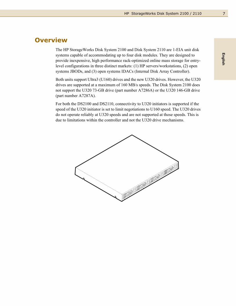
OverviewThe HP StorageWorks Disk System 2100 and Disk System 2110 are 1-EIA unit disk systems capable of accommodating up to four disk modules. They are designed to provide inexpensive, high performance rack-optimized online mass storage for entry-level configurations in three distinct markets: (1) HP servers/workstations, (2) open systems JBODs, and (3) open systems IDACs (Internal Disk Array Controller).
Both units support Ultra3 (U160) drives and the new U320 drives. However, the U320 drives are supported at a maximum of 160 MB/s speeds. The Disk System 2100 does not support the U320 73-GB drive (part number A7286A) or the U320 146-GB drive (part number A7287A).
For both the DS2100 and DS2110, connectivity to U320 initiators is supported if the speed of the U320 initiator is set to limit negotiations to U160 speed. The U320 drives do not operate reliably at U320 speeds and are not supported at those speeds. This is due to limitations within the controller and not the U320 drive mechanisms.
HP StorageWorks Disk System 2100 / 21108
Components of the Disk System
Front Panel
The disk modules can be accessed from the front of the disk system. It can accept up to 4 low profile disk drives. If your storage system contains less than 4 disk modules, the remaining empty slots contain filler panels. These filler panels (part number A6198-60002) ensure that the proper cooling is maintained within the storage system. Remove filler panels only when a disk module is added to the system.
Disk Module LEDs
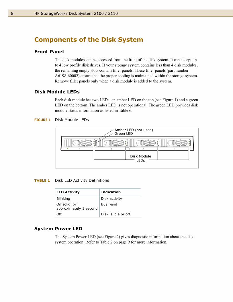
Each disk module has two LEDs: an amber LED on the top (see Figure 1) and a green LED on the bottom. The amber LED is not operational. The green LED provides disk module status information as listed in Table 6.
FIGURE 1 Disk Module LEDs
TABLE 1 Disk LED Activity Definitions
System Power LED
The System Power LED (see Figure 2) gives diagnostic information about the disk system operation. Refer to Table 2 on page 9 for more information.
LED Activity Indication
Blinking Disk activity
On solid for approximately 1 second
Bus reset
Off Disk is idle or off
Disk Module LEDs
Amber LED (not used)Green LED

9HP StorageWorks Disk System 2100 / 2110English
FIGURE 2 System Power LED
TABLE 2 System Power LED Activity Definitions
Rear Panel
FIGURE 3 Rear View of the Disk System
FIGURE 4 Power Button
With the power button in the “ON” position, power is supplied to the disk system.
LED Activity Indication
Blinking Malfunction - either a fan is not operating properly or internal voltage is too low.
On solid Disk system is operating properly.
Off Disk system is off.
System Power LED
PowerButton
ACPower
Connector
LVD/SE SCSIPort
SCSI AddressSwitch
LVD/SE SCSIPort
PowerButton
HP StorageWorks Disk System 2100 / 211010
SCSI ID Switch
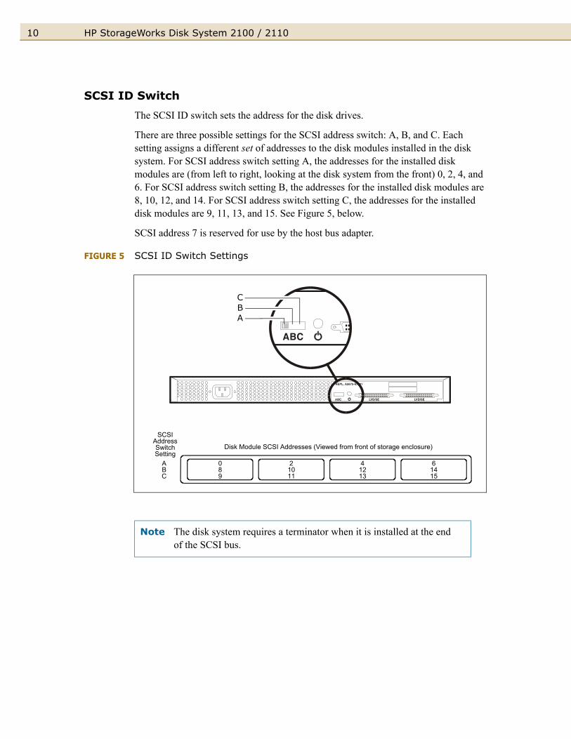
The SCSI ID switch sets the address for the disk drives.
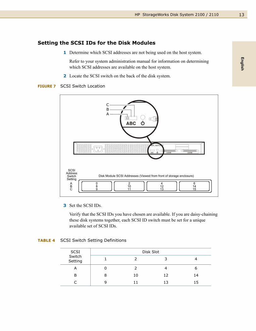
There are three possible settings for the SCSI address switch: A, B, and C. Each setting assigns a different set of addresses to the disk modules installed in the disk system. For SCSI address switch setting A, the addresses for the installed disk modules are (from left to right, looking at the disk system from the front) 0, 2, 4, and 6. For SCSI address switch setting B, the addresses for the installed disk modules are 8, 10, 12, and 14. For SCSI address switch setting C, the addresses for the installed disk modules are 9, 11, 13, and 15. See Figure 5, below.
SCSI address 7 is reserved for use by the host bus adapter.
FIGURE 5 SCSI ID Switch Settings
Note The disk system requires a terminator when it is installed at the end of the SCSI bus.
089
21011
41213
61415
ABC
SCSIAddressSwitchSetting
Disk Module SCSI Addresses (Viewed from front of storage enclosure)
CBA

11HP StorageWorks Disk System 2100 / 2110English
Power Connector
FIGURE 6 AC Power Connector Location
Electrical Requirements
AC Site Requirements
Overcurrent protection devices are required for each cabinet where the disk system is installed. They must be positioned between the power source and the disk system. These protective devices must not trip when exposed to an inrush current of 30 amps lasting 5 ms.
I
Note These protection devices must meet all applicable electrical safety requirements and be approved for the intended purpose.
TABLE 3 AC Power Requirements
Electrical Element Requirements
Voltage 100-240 VAC
Frequency 50-60 Hz
Input Current < 1 amp
Maximum Surge Current 30 amps peak
ACPower
Connector
HP StorageWorks Disk System 2100 / 211012
Installing the Disk System
Hardware Requirements
The following hardware is included with the disk system:
One power cord comes with each disk system.
Your host computer must have one of the following:
■ An on board UltraSCSI port
■ An UltraSCSI host bus adapter board installed in the host system:
– A6828A Single Port Ultra160 SCSI Host Bus Adapter (HP Series 9000 only)
– A6829A Dual Port Ultra160 SCSI Host Bus Adapter (HP Series 9000 only)
– A7059A Windows and Linux Ultra160 SCSI Host Bus Adapter
– A7060A Windows and Linux Dual Port Ultra160 SCSI Host Bus Adapter
– P3413A Single Port Ultra3 SCSI Host Bus Adapter for HP Netservers
The following accessories are available for your storage disk system:
■ A6828A Single Port Ultra160 SCSI Host Bus Adapter
■ A6829A Dual Port Ultra160 SCSI Host Bus Adapter
■ C2364A High Density 68-pin Terminator for LVD or Single-Ended
The DS2100 and DS2110 support a maximum SCSI speed of U160. Connectivity to U320 initiators is supported if the speed of the U320 initiator is set to limit negotiations to U160 speed. U320 drives do not operate reliably at U320 speeds and are not supported at those speeds. This is due to limitations within the controller and not the U320 disk mechanisms. Contact your HP support representative for assistance with the configuration.
Preparing for Installation
Before the disk system is ready for installation, its SCSI IDs must be set and the host system must be prepared to recognize the newly installed disk system. See your operating system administration manual for configuration procedures for the host bus adapter.
13HP StorageWorks Disk System 2100 / 2110English
Setting the SCSI IDs for the Disk Modules
1 Determine which SCSI addresses are not being used on the host system.
Refer to your system administration manual for information on determining which SCSI addresses are available on the host system.
2 Locate the SCSI switch on the back of the disk system.
FIGURE 7 SCSI Switch Location
3 Set the SCSI IDs.
Verify that the SCSI IDs you have chosen are available. If you are daisy-chaining these disk systems together, each SCSI ID switch must be set for a unique available set of SCSI IDs.
TABLE 4 SCSI Switch Setting Definitions
SCSI SwitchSetting
Disk Slot
1 2 3 4
A 0 2 4 6
B 8 10 12 14
C 9 11 13 15
089
21011
41213
61415
ABC
SCSIAddressSwitchSetting
Disk Module SCSI Addresses (Viewed from front of storage enclosure)
CBA

HP StorageWorks Disk System 2100 / 211014
Keep in mind that the host bus adapter should have the highest SCSI address priority. See Table 5 below.
TABLE 5 SCSI Address Priority
Installing the Disk SystemSee the installation instructions enclosed with your rackmount kit.
Connect the SCSI Cables
1 Make sure that the host system has been powered down.
2 Connect one end of an Ultra SCSI cable (included in the shipping box) to the host system. For the SCSI port location on your host system, refer to your host system’s documentation.
3 Connect the other end of the SCSI cable to one of the LVD/SE ports on the rear of the disk system.
FIGURE 8 SCSI Port Locations
SCSI ID 7 6 5 4 3 2 1 0 15 14 13 12 11 10 9 8
Priority Highest Lowest
LVD/SE SCSIPort
LVD/SE SCSIPort

15HP StorageWorks Disk System 2100 / 2110English
4 Determine if this disk system is at the beginning or end of the SCSI bus.
– If the disk system is at the end of the SCSI bus (you are not going to daisy-chain another device off this one), install the appropriate terminator (part number 5183-2657) on the available SCSI port and go to “Connecting the Power Cable” (see Figure 9 on page 16).
– If the disk system is at the beginning or middle of the SCSI bus (you are going to daisy-chain another device off this one), consider the following:
• Due to SCSI ID restrictions, no more than three of these disk systems can be daisy-chained together.
• For the DS2110, use only 0.5-meter cable between enclosures in daisy-chain configurations. Longer cable lengths between enclosures are not supported.
• Ensure that the SCSI IDs assigned for the disk drives in the second disk system or other peripheral are not already assigned to another device on the SCSI bus. Refer to “Setting the SCSI IDs for the Disk Modules” (see Figure 7 on page 13 for the SCSI IDs assigned for each SCSI switch setting).
• If you connected the SCSI cable to the on-board UltraSCSI port on the host system, verify that the SCSI IDs assigned to the disk drives in the second disk system or additional peripherals are not already assigned to any other peripherals installed in the host system.
• For the DS2100, the overall SCSI bus length cannot exceed12 meters. For the DS2110, the overall SCSI bus length cannot exceed 9 meters.
The SCSI bus length for the disk system internal cables is 1.1 meters. If another type of peripheral is being connected on this SCSI bus, refer to that peripheral’s documentation for its internal SCSI cable length.
5 Connect one end of an Ultra SCSI cable (get it from the shipping box) to the available SCSI port on the rear of the first disk system on the SCSI bus.
6 Connect the other end of the Ultra SCSI cable to the SCSI IN port on the rear of the second disk system on the SCSI bus.
7 Repeat Steps 3, 5, and 6 for the last disk system on the SCSI bus if three disk systems are being installed. Keep in mind the maximum bus length (12 meters).
8 Install a terminator if the device is the last one on the bus. For supported terminators, see Table 10 on page 33 or Table 12 on page 34.
Note The disk system, when connected at the end of a SCSI bus, requires a terminator. Refer to the documentation that came with your wide SCSI device to determine if it needs a terminator or not. Narrow SCSI devices at the end of a daisy-chain always require a terminator.

HP StorageWorks Disk System 2100 / 211016
Connecting the Power Cable
FIGURE 9 AC Power Connector Location
Powering On and Off
Power On the Disk System
1 Press the power button and release it. The power button will stay in a depressed position, indicating that the power is on.
See Figure 10 on page 17 for the location of the power button.
2 Confirm that the disk system is running properly by checking the system power LED and the disk module LEDs at the front of your disk system. A system reboot may be necessary to assure that the host system recognizes the disk drives within the disk system.
Refer to “Front Panel” on page 3 for explanations of the LED functions and their meanings.
Ensure that the connection of multiple units to the supply circuit does not overload the supply overcurrent protection or the supply wiring. Refer to the storage electrical ratings when determining the correct branch circuit rating for your installation. See Table 3 on page 11.
CAUTION
ACPower
Connector
17HP StorageWorks Disk System 2100 / 2110English
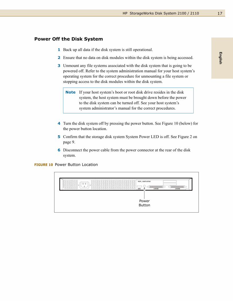
Power Off the Disk System
1 Back up all data if the disk system is still operational.
2 Ensure that no data on disk modules within the disk system is being accessed.
3 Unmount any file systems associated with the disk system that is going to be powered off. Refer to the system administration manual for your host system’s operating system for the correct procedure for unmounting a file system or stopping access to the disk modules within the disk system.
4 Turn the disk system off by pressing the power button. See Figure 10 (below) for the power button location.
5 Confirm that the storage disk system System Power LED is off. See Figure 2 on page 9.
6 Disconnect the power cable from the power connector at the rear of the disk system.
FIGURE 10 Power Button Location
Note If your host system’s boot or root disk drive resides in the disk system, the host system must be brought down before the power to the disk system can be turned off. See your host system’s system administrator’s manual for the correct procedures.
PowerButton
HP StorageWorks Disk System 2100 / 211018
Adding Disk ModulesDisk modules can be added, removed, and replaced while the disk system is running. Because the disk modules can be handled in this way, they are called hot-pluggable.
The SCSI addresses for the disks are set using the addressing switches on the back of the disk system. You can determine the assigned SCSI addresses by looking at the SCSI address switch settings at the rear of the disk system.
If your storage system contains less than 4 disk modules, the remaining empty slots require filler panels. These filler panels ensure that the proper cooling is maintained within the storage system.
The system administration procedure for adding a disk module is operating system specific. You must decide where the disk module is to be installed and install it. Once the disk module is installed, the operating system must be configured to recognize it.
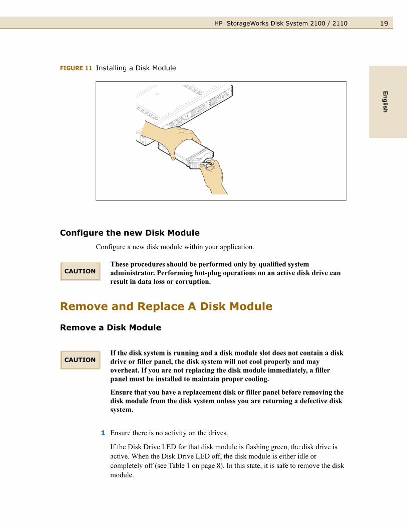
Add a Disk Module
1 Select an available slot for the new disk module. Note the slot chosen for application configuration.
2 Remove the disk module filler panel. Store the filler panel for future use.
3 Hold the locking handle open on the disk drive. Push the locking lever to the left to release the latch.
4 Slide the disk into the appropriate slot.
5 Gently push the drive until the locking mechanism engages. When the disk module is completely installed, an audible click can be heard.
6 Close the locking handle completely, using gentle downward pressure.
19HP StorageWorks Disk System 2100 / 2110English
FIGURE 11 Installing a Disk Module
Configure the new Disk Module
Configure a new disk module within your application.
Remove and Replace A Disk Module
Remove a Disk Module
1 Ensure there is no activity on the drives.
If the Disk Drive LED for that disk module is flashing green, the disk drive is active. When the Disk Drive LED off, the disk module is either idle or completely off (see Table 1 on page 8). In this state, it is safe to remove the disk module.
These procedures should be performed only by qualified system administrator. Performing hot-plug operations on an active disk drive can result in data loss or corruption.
If the disk system is running and a disk module slot does not contain a disk drive or filler panel, the disk system will not cool properly and may overheat. If you are not replacing the disk module immediately, a filler panel must be installed to maintain proper cooling.
Ensure that you have a replacement disk or filler panel before removing the disk module from the disk system unless you are returning a defective disk system.
CAUTION
CAUTION
HP StorageWorks Disk System 2100 / 211020
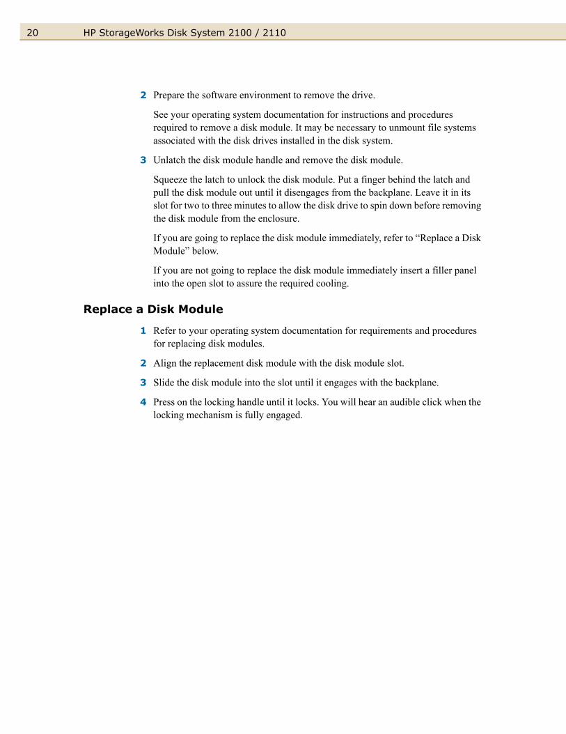
2 Prepare the software environment to remove the drive.
See your operating system documentation for instructions and procedures required to remove a disk module. It may be necessary to unmount file systems associated with the disk drives installed in the disk system.
3 Unlatch the disk module handle and remove the disk module.
Squeeze the latch to unlock the disk module. Put a finger behind the latch and pull the disk module out until it disengages from the backplane. Leave it in its slot for two to three minutes to allow the disk drive to spin down before removing the disk module from the enclosure.
If you are going to replace the disk module immediately, refer to “Replace a Disk Module” below.
If you are not going to replace the disk module immediately insert a filler panel into the open slot to assure the required cooling.
Replace a Disk Module
1 Refer to your operating system documentation for requirements and procedures for replacing disk modules.
2 Align the replacement disk module with the disk module slot.
3 Slide the disk module into the slot until it engages with the backplane.
4 Press on the locking handle until it locks. You will hear an audible click when the locking mechanism is fully engaged.

21HP StorageWorks Disk System 2100 / 2110English
Remove the Disk System
Reverse the installation instructions enclosed with the rackmount kit for your cabinet:
■ A5679A - Hewlett-Packard Rack Systems/E for Enterprise Systems
■ A5680A - all other Hewlett-Packard rack systems for Enterprise Systems purchased before November 1998.
■ A6532A - Hewlett-Packard Rack Systems/E for Commercial Systems
■ A6533A - all other Hewlett-Packard rack systems for Commercial Systems purchased before November 1998.
If your disk system is a factory-integrated unit, see the figure below for removal instructions.
FIGURE 12 Removing the Disk System
If you are exchanging a desktop disk system, be sure to remove and store the plastic Desktop Disk System Cover for use on the replacement disk system.
Some data paths may be slot-dependent. Be sure to note the slot from which the disk module is removed so it can be installed in the same slot in the replacement disk system.
CAUTION
HP StorageWorks Disk System 2100 / 211022
Setting Up the Hardware Event Monitor (HP-UX Only)
Hardware event monitors run on HP-UX hosts, versions 10.20 and later. The Disk Monitor (disk_em) monitors all disks bound to sdisk drivers. Consequently, if the Disk Monitor is active on your host, it is already set up to monitor the disks of a new disk system. If you need to install or activate the Disk Monitor, refer to the EMS Hardware Monitors User’s Guide in the latest IPR Support Media or on the Web (http://www.docs.hp.com/hpux/diag/).
The way you configure the monitor determines, among other things, where event messages will be sent and what level of severity will be reported.
Configuration OverviewThe following steps will help you identify and resolve disk system failures:
1 Gather information from all sources:
– Hardware event notifications (page 25)
– Disk system LED status (page 25)
– Online information tools (page 26)
2 Isolate the cause of the problem (Table 7 on page 30).
3 Correct the problem. (See page 19 for disk module removal and replacement.)
4 Verify operational status with ioscan or other host utilities.
Note This Disk Monitor should not be confused with the EMS disk monitor that is used to monitor LVM resources.
23HP StorageWorks Disk System 2100 / 2110English
Event Notification (HP-UX Only)
The Disk Monitor, an EMS hardware event monitor, reports changes in disk status. Depending on how the monitor is set up, it sends messages to the console, an e-mail address, a log file, or a third-party application. These messages give early notice of a disk problem. Events include media errors, failed read and write attempts, invalid commands, changed operating parameters, failed diagnostics, and many others.
Event severity ranges from critical to informational:
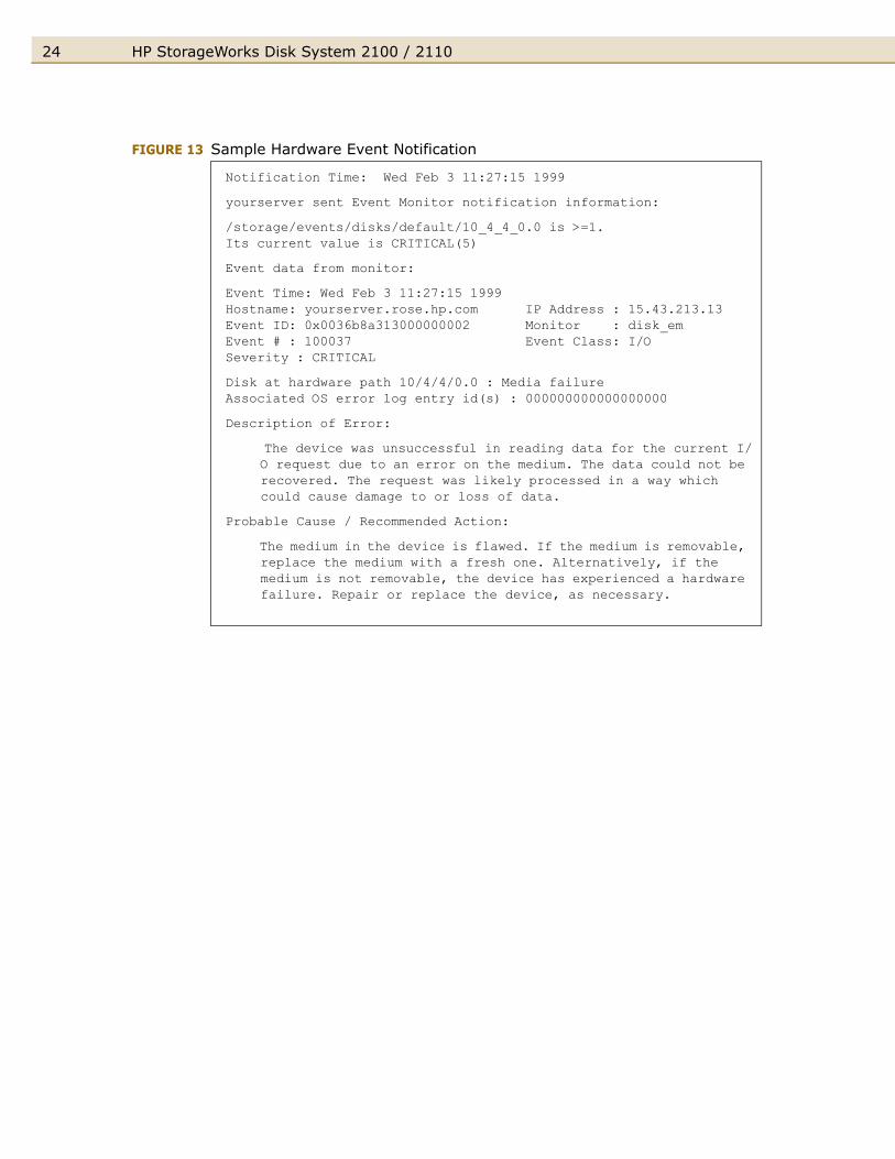
Event messages (see Figure 13) contain the following types of information:
■ Message Data – Date and time the message was sent, the source and destination of the message, and the severity level.
■ Event Data – Date and time of the event, the host, event ID, name of the monitor, event number, event class, severity level, hardware path, associated OS error log entry ID.
■ Error Description – Narrative information indicating the component that experienced the event and the nature of the event.
■ Probable Cause/Recommended Action – The cause of the event and suggested steps toward a solution. This information should be the first step in troubleshooting.
Critical An event that causes data loss, host system downtime, or other loss of service. Host system operation will be affected if the disk system continues to be used without correction. Immediate action is required. For example, read data could not be recovered.
Serious An event that may cause data loss, host system downtime, or other loss of service if left uncorrected. Host system and hardware operation may be adversely affected. The problem needs repair as soon as possible. For example, the request queue is full.
Warning An event that could escalate to a serious condition if not corrected. Host system operation should not be affected and normal use of the disk system can continue. Repair is needed but at a convenient time. For example, the bus failed to reset.
Information An event that is expected as part of the normal operation of the hardware. No action is required. For example, write protection was switched on or off.
HP StorageWorks Disk System 2100 / 211024
FIGURE 13 Sample Hardware Event Notification
Notification Time: Wed Feb 3 11:27:15 1999
yourserver sent Event Monitor notification information:
/storage/events/disks/default/10_4_4_0.0 is >=1.Its current value is CRITICAL(5)
Event data from monitor:
Event Time: Wed Feb 3 11:27:15 1999Hostname: yourserver.rose.hp.com IP Address : 15.43.213.13Event ID: 0x0036b8a313000000002 Monitor : disk_emEvent # : 100037 Event Class: I/OSeverity : CRITICAL
Disk at hardware path 10/4/4/0.0 : Media failure Associated OS error log entry id(s) : 000000000000000000
Description of Error:
The device was unsuccessful in reading data for the current I/O request due to an error on the medium. The data could not be recovered. The request was likely processed in a way which could cause damage to or loss of data.
Probable Cause / Recommended Action:
The medium in the device is flawed. If the medium is removable, replace the medium with a fresh one. Alternatively, if the medium is not removable, the device has experienced a hardware failure. Repair or replace the device, as necessary.
25HP StorageWorks Disk System 2100 / 2110English
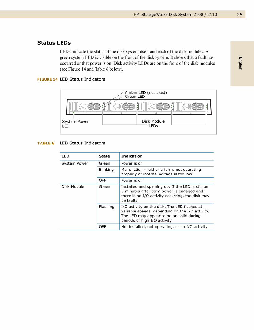
Status LEDs
LEDs indicate the status of the disk system itself and each of the disk modules. A green system LED is visible on the front of the disk system. It shows that a fault has occurred or that power is on. Disk activity LEDs are on the front of the disk modules (see Figure 14 and Table 6 below).
FIGURE 14 LED Status Indicators
TABLE 6 LED Status Indicators
LED State Indication
System Power Green Power is on
Blinking Malfunction - either a fan is not operating properly or internal voltage is too low.
OFF Power is off
Disk Module Green Installed and spinning up. If the LED is still on 3 minutes after term power is engaged and there is no I/O activity occurring, the disk may be faulty.
Flashing I/O activity on the disk. The LED flashes at variable speeds, depending on the I/O activity. The LED may appear to be on solid during periods of high I/O activity.
OFF Not installed, not operating, or no I/O activity
Disk Module LEDs
System Power LED
Amber LED (not used)Green LED

HP StorageWorks Disk System 2100 / 211026
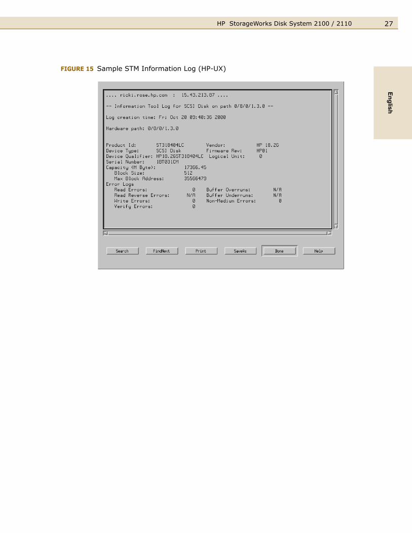
View Disk Status HP-UX and MPE/iX utilities provide descriptive and diagnostic information about disks, including disk type, firmware revision, and errors. On HP-UX and MPE/iX 6.5 or later, the disk utility is Support Tools Manager (STM). For all other operating systems, consult the appropriate system administration manual for disk module status checking procedures.
STM Disk Information: HP-UX
STM displays the last-generated Information Log for a selected disk. Start STM and run the Information tool as follows.
1 Log on the system.
2 At the system prompt, type xstm&. STM starts and displays a graphic of the devices on the system.
3 Select the desired disk.
4 Select Information from the Tools menu.
5 To generate a current log, select Run. The log will be displayed as soon as it is generated
6 To view a log without updating the contents, select Information Log.
7 Select Done when you have finished viewing the information.
8 To quit STM, type exit.
Figure 15 shows a sample Information Log.
27HP StorageWorks Disk System 2100 / 2110English
FIGURE 15 Sample STM Information Log (HP-UX)

HP StorageWorks Disk System 2100 / 211028
STM Disk Information: MPE/iX 6.5 or Later
STM displays the last-generated Information Log for a selected disk. Start STM and run the Information tool as follows.
1 Log on the system.
2 At the system prompt (:), type vsclose <physical volume number>. This removes the disk from use.
3 At the system prompt (:), type cstm. STM starts.
4 At the cstm prompt, type map. STM displays a list of all the disks installed on the system.
5 Select the desired disk by typing select device <number>; for example, select device 15.
6 Type information. STM updates the system map.
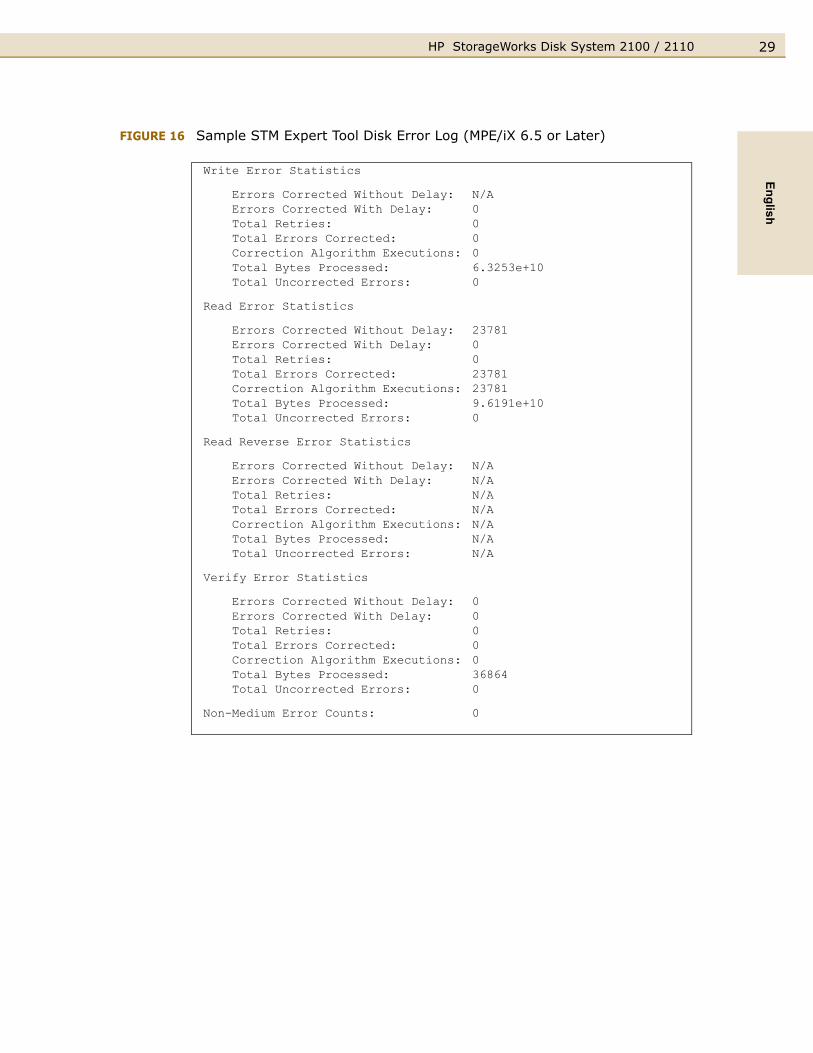
7 To display the information log, type infolog. A sample information log is shown in Figure 16.
29HP StorageWorks Disk System 2100 / 2110English
FIGURE 16 Sample STM Expert Tool Disk Error Log (MPE/iX 6.5 or Later)
Write Error Statistics
Errors Corrected Without Delay: N/AErrors Corrected With Delay: 0Total Retries: 0Total Errors Corrected: 0Correction Algorithm Executions: 0Total Bytes Processed: 6.3253e+10Total Uncorrected Errors: 0
Read Error Statistics
Errors Corrected Without Delay: 23781Errors Corrected With Delay: 0Total Retries: 0Total Errors Corrected: 23781Correction Algorithm Executions: 23781Total Bytes Processed: 9.6191e+10Total Uncorrected Errors: 0
Read Reverse Error Statistics
Errors Corrected Without Delay: N/AErrors Corrected With Delay: N/ATotal Retries: N/ATotal Errors Corrected: N/ACorrection Algorithm Executions: N/ATotal Bytes Processed: N/ATotal Uncorrected Errors: N/A
Verify Error Statistics
Errors Corrected Without Delay: 0Errors Corrected With Delay: 0Total Retries: 0Total Errors Corrected: 0Correction Algorithm Executions: 0Total Bytes Processed: 36864Total Uncorrected Errors: 0
Non-Medium Error Counts: 0

HP StorageWorks Disk System 2100 / 211030
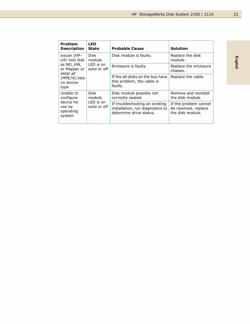
Isolating Faults
Table 7 lists the probable causes and solutions for problems you may detect on the disk system. When more than one problem describes your situation, investigate the first solution that applies. The table lists the most basic problems first and excludes them from subsequent problem descriptions.
Erratic LED behavior on the disk system could be observed in the following situations:
■ When a server that is connected to a Disk System 2110 is powered down or loses power (and the disk system remains powered on)
■ When the disk system is powered up when connected to a downed server
■ When an unconnected disk system is powered up
An example of this LED behavior is the LEDs staying lit solidly. This condition is caused by the disk system being deprived of term power when the server loses power or is powered down. The disk system does not provide its own term power. It relies on the host bus adapter to which it is connected for term power.
TABLE 7 Troubleshooting Table
Problem Description
LEDState Probable Cause Solution
Disk system fails to power on when installed
System power LED is off
Power cord is not plugged in. Plug in the power cord.
The power button is not pressed.
Press the power button.
AC breaker is tripped or AC power source has failed.
Confirm AC power availability.
The PDU/PDRU is defective. Replace the PDU/PDRU.
Enclosure chassis is faulty. Replace the enclosure chassis.
System power LED is blinking
Power supply is defective. Replace the enclosure chassis.
Cooling fans are not spinning at the correct speed.
Replace the enclosure chassis.
Operating system reports errors on a device
Disk module LED is on solid or off
Use diagnostic utilities to determine disk status.
Depending on the results, monitor or replace disk module.
31HP StorageWorks Disk System 2100 / 2110English
ioscan (HP-UX) lists disk as NO_HW, or Mapper or dstat all (MPE/iX) lists no device type
Disk module LED is on solid or off
Disk module is faulty. Replace the disk module.
Enclosure is faulty. Replace the enclosure chassis.
If the all disks on the bus have this problem, the cable is faulty.
Replace the cable.
Unable to configure device for use by operating system
Disk module LED is on solid or off
Disk module possibly not correctly seated.
Remove and reinstall the disk module.
If troubleshooting an existing installation, run diagnostics to determine drive status.
If the problem cannot be resolved, replace the disk module.
Problem Description
LEDState Probable Cause Solution
HP StorageWorks Disk System 2100 / 211032
Reference Information
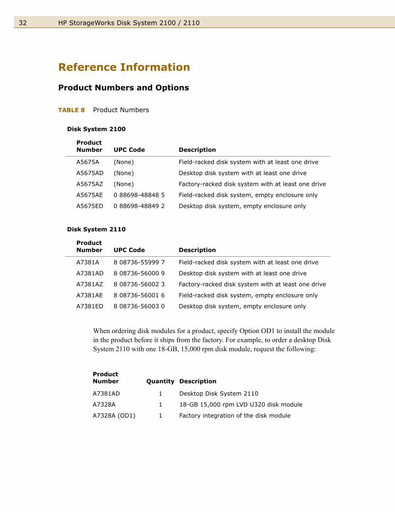
Product Numbers and Options
TABLE 8 Product Numbers
When ordering disk modules for a product, specify Option OD1 to install the module in the product before it ships from the factory. For example, to order a desktop Disk System 2110 with one 18-GB, 15,000 rpm disk module, request the following:
Disk System 2100
Product Number UPC Code Description
A5675A (None) Field-racked disk system with at least one drive
A5675AD (None) Desktop disk system with at least one drive
A5675AZ (None) Factory-racked disk system with at least one drive
A5675AE 0 88698-48848 5 Field-racked disk system, empty enclosure only
A5675ED 0 88698-48849 2 Desktop disk system, empty enclosure only
Disk System 2110
Product Number UPC Code Description
A7381A 8 08736-55999 7 Field-racked disk system with at least one drive
A7381AD 8 08736-56000 9 Desktop disk system with at least one drive
A7381AZ 8 08736-56002 3 Factory-racked disk system with at least one drive
A7381AE 8 08736-56001 6 Field-racked disk system, empty enclosure only
A7381ED 8 08736-56003 0 Desktop disk system, empty enclosure only
Product Number Quantity Description
A7381AD 1 Desktop Disk System 2110
A7328A 1 18-GB 15,000 rpm LVD U320 disk module
A7328A (OD1) 1 Factory integration of the disk module
33HP StorageWorks Disk System 2100 / 2110English
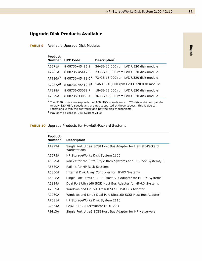
Upgrade Disk Products Available
TABLE 9 Available Upgrade Disk Modules
TABLE 10 Upgrade Products for Hewlett-Packard Systems
Product Number UPC Code Description1
A6571A 8 08736-45416 2 36-GB 10,000 rpm LVD U320 disk module
A7285A 8 08736-45417 9 73-GB 10,000 rpm LVD U320 disk module
A7286A2 8 08736-45418 62 73-GB 15,000 rpm LVD U320 disk module
A7287A2 8 08736-45419 32 146-GB 10,000 rpm LVD U320 disk module
A7328A 8 08736-33052 7 18-GB 15,000 rpm LVD U320 disk module
A7329A 8 08736-33053 4 36-GB 15,000 rpm LVD U320 disk module
1 The U320 drives are supported at 160 MB/s speeds only. U320 drives do not operate reliably 320 MB/s speeds and are not supported at those speeds. This is due to limitations within the controller and not the disk mechanisms.
2 May only be used in Disk System 2110.
Product Number Description
A4999A Single Port Ultra2 SCSI Host Bus Adapter for Hewlett-Packard Workstations
A5675A HP StorageWorks Disk System 2100
A5679A Rail kit for the Rittal Style Rack Systems and HP Rack Systems/E
A5680A Rail kit for HP Rack Systems
A5856A Internal Disk Array Controller for HP-UX Systems
A6828A Single Port Ultra160 SCSI Host Bus Adapter for HP-UX Systems
A6829A Dual Port Ultra160 SCSI Host Bus Adapter for HP-UX Systems
A7059A Windows and Linux Ultra160 SCSI Host Bus Adapter
A7060A Windows and Linux Dual Port Ultra160 SCSI Host Bus Adapter
A7381A HP StorageWorks Disk System 2110
C2364A LVD/SE SCSI Terminator (HDTS68)
P3413A Single Port Ultra3 SCSI Host Bus Adapter for HP Netservers

HP StorageWorks Disk System 2100 / 211034
TABLE 11 Replaceable Parts
TABLE 12 Supported HP Cables and Terminators
Product Number Description
ReplaceablePart Numbers
Customer Replaceable Unit (CRU)
Field Replaceable Unit (FRU)
A5675A DS2100 Base Disk System Assembly A5675-69003 Yes Yes
A6198A Disk Filler Panel A6198-67002 Yes Yes
A6571A* 36-GB 10,000 rpm LVD U320 disk mod. A6571-69001 Yes Yes
A7285A* 73-GB 10,000 rpm LVD U320 disk mod. A7285-69001 Yes Yes
A7286A* 73-GB 15,000 rpm LVD U320 disk mod. A7286-69001 Yes Yes
A7287A* 146-GB 10,000 rpm LVD U320 disk mod. A7287-69001 Yes Yes
A7328A* 18-GB 15,000 rpm LVD U320 disk mod. A7328-69001 Yes Yes
A7329A* 36-GB 15,000 rpm LVD U320 disk mod. A7329-69001 Yes Yes
A7381A DS2110 Base Disk System Assembly A7381-69001 Yes Yes
Desktop Disk System Cover 5065-5217 No Yes
Desktop Disk System Feet 0403-0285 No Yes
* The U320 drives are supported at 160 MB/s speeds only. U320 drives do not operate reliably 320 MB/s speeds and are not supported at those speeds. This is due to limitations within the controller and not the disk mechanisms.
OrderNumber Description
PartNumber
C2978B 0.5-meter HDT S68 SCSI multimode cable 5183-2670
C2911C 1.0-meter HDT S68 SCSI multimode cable 5183-2671
C2979B 1.5-meter HDT S68 SCSI multimode cable 5183-2672
C2924C 2.5-meter HDT S68 SCSI multimode cable 5183-2673
C7521A 5.0-meter HDT S68 SCSI multimode cable 5183-2678
C2361B 1.0-meter VHDT S68/HDT S68 SCSI multimode cable 5183-2674
C2362B 2.5-meter VHDT S68/HDT S68 SCSI multimode cable 5183-2675
C2365B 5.0-meter VHDT S68/HDT S68 SCSI multimode cable 5183-2676
C2364A SCSI Terminator LVD/SE HDTS68 5183-2657
35HP StorageWorks Disk System 2100 / 2110English
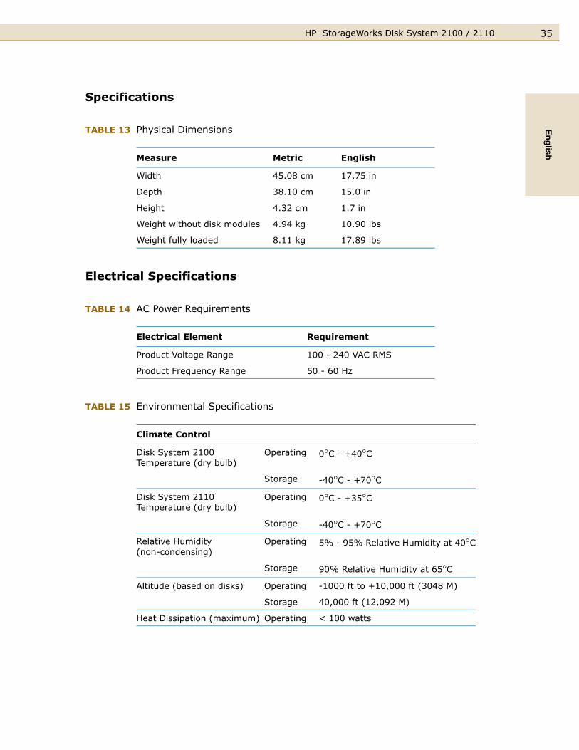
Specifications
TABLE 13 Physical Dimensions
Electrical Specifications
TABLE 14 AC Power Requirements
TABLE 15 Environmental Specifications
Measure Metric English
Width 45.08 cm 17.75 in
Depth 38.10 cm 15.0 in
Height 4.32 cm 1.7 in
Weight without disk modules 4.94 kg 10.90 lbs
Weight fully loaded 8.11 kg 17.89 lbs
Electrical Element Requirement
Product Voltage Range 100 - 240 VAC RMS
Product Frequency Range 50 - 60 Hz
Climate Control
Disk System 2100 Temperature (dry bulb)
Operating 0°C - +40°C
Storage -40°C - +70°CDisk System 2110 Temperature (dry bulb)
Operating 0°C - +35°C
Storage -40°C - +70°CRelative Humidity(non-condensing)
Operating 5% - 95% Relative Humidity at 40°C
Storage 90% Relative Humidity at 65°CAltitude (based on disks) Operating -1000 ft to +10,000 ft (3048 M)
Storage 40,000 ft (12,092 M)
Heat Dissipation (maximum) Operating < 100 watts
HP StorageWorks Disk System 2100 / 211036
Operating Temperatures
If the storage system is installed in a multi-unit rack assembly, the operating ambient temperature of the rack environment may exceed room ambient temperature. For the Disk System 2100 the rack environment ambient temperature cannot exceed 40° Celsius (104° Fahrenheit). For the Disk System 2110 the rack environment ambient temperature cannot exceed 35° Celsius (95° Fahrenheit).
If your storage system contains less than 4 disk modules, the remaining empty slots require filler panels. These filler panels (part number A6198-60002) ensure that the proper cooling is maintained within the storage system.
Regulatory Statements
Safety Certifications
UL listed, UL 1950:1995 – 3rd Edition
CSA certified, C22.2 No. 950:1995
TUV certified with GS mark, EN 60950:1992 + A1:1993, A2:1993, A3:1995, A4:1997, A11:1997
CE mark (see I. Declaration of Conformity on page 39)
EMC Compliance
Australia: AS/NZS 3548, Class A
Canada: ICES-003, Class A
China: GB9254-88
European Union: EN55022 Class A, EN55024
Japan: VCCI Class A
Taiwan: CNS 13438, Class A
US: 47 CFR Parts 2 & 15, Class A
A. FCC Notice for United States
The Federal Communications Commission (in 47 CFR 15.105) has specified that the following notice be brought to the attention of the users of this product.
This equipment has been tested and found to comply with the limits for a Class A digital device, pursuant to Part 15 of the FCC Rules. These limits are designed to provide reasonable protection against harmful interference when the equipment is operated in a commercial environment. This equipment generates, uses, and can

37HP StorageWorks Disk System 2100 / 2110English
radiate radio frequency energy and, if not installed and used in accordance with the instruction manual, may cause harmful interference to radio communications.
Hewlett-Packard’s certification tests were conducted with a Hewlett-Packard supported computer system and Hewlett-Packard shielded cables, such as those you received with your storage product. Changes or modifications not expressly approved by Hewlett-Packard could void the user’s authority to operate the equipment. Cables used with this device must be properly shielded to comply with the requirements of the FCC.
B. Canadian Notice (Avis Canadien)
This Class A digital apparatus meets all requirements of the Canadian Interference-Causing Equipment Regulations.
Cet appareil numérique de la classe A respecte toutes les exigences du Règlement sur le matériel brouilleur du Canada.
C. Notice for European Union
This is a Class A product. In a domestic environment this product may cause radio interference, in which case the user may be required to take adequate measures.
D. Notice for France
DECLARATION D'INSTALLATION ET DE MISE EN EXPLOITATION d'un matériel de traitement de l'information (ATI), classé A en fonction des niveaux de perturbations radioélectriques émis, définis dans la norme européenne EN 55022 concernant la Compatibilité Electromagnétique.
E. Notice for Japan
F. Harmonics Conformance (Japan)
HP StorageWorks Disk System 2100 / 211038
G. BSMI
H. Notice for Germany
Schalldruckpegel Lp = 55.0 dB(A)
Am Arbeitsplatz (operator position)
Normaler Betrieb (normal operation)
Nach ISO 7779:1999 (Typprüfung)

39HP StorageWorks Disk System 2100 / 2110English
I. Declaration of Conformity
DECLARATION OF CONFORMITYAccording to ISO/IEC Guide 22 and EN 45014
Manufacturer's Name: Hewlett-Packard Company
Manufacturer's Address: 11311 Chinden Blvd.
Boise, ID 83714
USA
Declares, that the product
Product Name: hp StorageWorks disk system 2100 and 2110
Product Number: A5675A/AD/AZ/ED, A5676A/AD, and
A7381A/AD/AE/AZ/ED
Regulatory Model Number: BOISA-0301
Product Options: All
Conforms to the following Product Specifications:
Safety: IEC 60950:1991+A1+A2+A3+A4 / EN 60950:1992+A1+A2+A3+A4+A11
GB 4943:1995
IEC 60825-1:1993 / EN 60825-1:1994 +A11, Class 1 (Laser/LED)
EMC: CISPR 22:1997+A1 / EN 55022:1998 +A1 Class A 1
GB 9254:1988
CISPR 24:1997 / EN 55024:1998
IEC 61000-3-2:1995 / EN 61000-3-2:1995 + A14
IEC 61000-3-3:1994 / EN 61000-3-3:1995
Supplementary Information:
The product herewith complies with the requirements of the Low Voltage Directive
73/23/EEC and the EMC Directive 89/336/EEC and carries the CE-marking accordingly.
1) The Product was tested in a worst-case configuration which maximizes RFI
emissions.
Boise, ID USA
March 7, 2003
European contact for regulatory topics only: Hewlett-Packard GmbH, HQ-TRE, Herrenberger Strasse 140, and D-71034
Böblingen (FAX: + 49-7031-14-3143)

HP StorageWorks Disk System 2100 / 211040
Product Web SiteFor the most current information about the HP StorageWorks Disk System 2100, visit the support Web site located at http://www.hp.com/support/ds2100
For the most current information about the HP StorageWorks Disk System 2110, visit the support Web site located at http://www.hp.com/support/ds2110.
Related DocumentsThe following resources contain information on using the system software interfaces to the HP StorageWorks Disk System 2100 / 2110:
■ Online Diagnostics (for HP 9000): Support Tools Manager Overview, available at http://docs.hp.com/hpux/diag/
■ HP-UX documentation, available at http://docs.hp.com

41HP StorageWorks Disk System 2100 / 2110English

HP StorageWorks Disk System 2100 / 211042