hp sata/sas hard drive and solid state drive · pdf filehp sata/sas hard drive and solid state...
TRANSCRIPT

HP SATA/SAS hard drive and SolidState Drive installation
This document describes how to install Serial ATA (SATA) and Serial Attached SCSI (SAS) hard drivesor Solid State Drives (SSD) in an internal hard drive bay. Throughout this document, all references tohard drives include solid state drives.
IMPORTANT: SATA 6 gigabit per second (Gb/s) drives are currently only supported on the HPZ210 CMT (Convertible Minitower) and HP Z210 SFF (Small Form Factor) Workstations. They shouldnot be installed or used in workstation products that do not support SATA 6 Gb/s drives.
Kit contents● A SATA or SAS hard drive or SSD
● Multiple SATA cables (each of a different length and with different connector orientationcombinations)
● SAS-to-SATA adapter or SAS-to-SATA cable (included with SAS hard drives)
● Four 6-32 guide screws
● Installation instructions (this document)
● Warranty information
Tools requiredThe following may be required to install the hard drive:
● T-15 Torx screwdriver or flat-bladed screwdriver
© 2011 Hewlett-Packard Development Company, L.P. Microsoft, Windows, XP,and Windows Vista are U.S. registered trademarks of Microsoft Corporation.Printed in the U.S.
ENWW Kit contents 1

Your responsibilitiesYou are responsible for determining whether the product is appropriate for your use and will interfacewith other equipment without malfunction or damage. You are also responsible for backing up databefore installing any product and for regularly backing up data after installing the product. HP is notliable for any damage to equipment or data loss resulting from the use of any product. To determine thecompatibility of this product with your computer or workstation, view QuickSpecs athttp://www.hp.com/go/productbulletin.
Warnings and cautionsWARNING! Any surface or area of the equipment marked with this symbol indicates thepresence of a hot surface or hot component. If this surface is contacted, the potential for injury exists.To reduce the risk of injury from a hot component, enable the surface to cool before touching.
WARNING! Any surface or area of the equipment marked with this symbol indicates thepresence of an electrical shock hazard. To reduce the risk of injury from electrical shock, do not openany enclosed area marked with this symbol.
WARNING! To reduce the risk of electric shock or damage to your equipment:
— Do not disable the power cord grounding plug. The grounding plug is an important safety feature.
— Plug the power cord in a grounded (earthed) outlet that is easily accessible at all times.
— Disconnect power from the equipment by unplugging the power cord from the electrical outlet.
WARNING! To reduce the risk of serious injury, read the Safety & Comfort Guide. It describesproper computer setup, posture, health, and work habits for computer users, and provides importantelectrical and mechanical safety information. This guide is located at http://www.hp.com/ergo and onthe documentation CD (if one is included with the product).
WARNING! If a product is shipped in packaging marked with this symbol, , the product mustalways be lifted by two persons to avoid personal injury due to product weight.
CAUTION: Static electricity can damage the electronic components of the computer. Beforebeginning these procedures, be sure you discharge static electricity by briefly touching a groundedmetal object.
CAUTION: To prevent damage to the computer, observe the following Electrostatic Discharge (ESD)precautions while performing the system parts removal and replacement procedures:
— Work on a static-free mat.
— Wear a static strap to ensure that any accumulated electrostatic charge is discharged from yourbody to the ground.
— Create a common ground for the equipment you are working on by connecting the static-free mat,static strap, and peripheral units to that piece of equipment.
2 HP SATA/SAS hard drive and Solid State Drive installation ENWW

NOTE: HP accessories are for use in HP computer products. They have been extensively tested forreliability and are manufactured to high quality standards.
Step 1—Preparing for component installationNOTE: Computer models vary. All illustrations are examples only.
Accessing the internal components of the computer
1. If you need help preparing the computer for this installation, consult the removal and replacementprocedures in the service guide for your computer at http://www.hp.com/support/manuals.
2. Power down the computer, and then disconnect the power cord.
3. Power down all external devices, and then disconnect them from the computer.
4. Remove the side access panel.
Precautions for handling the drive
● Do not move the drive during operation.
● Avoid placing the drive in a location that is subject to extreme temperatures or mechanicalvibration.
● Keep the original packing materials for future transportation of the drive.
● If any object or liquid falls into the cabinet, immediately unplug the computer and have it checkedby an authorized service provider.
Step 2—Preparing and installing the hard driveIdentify your installation type from among the four types of internal hard drive installations detailed inthe following sections.
1. Computers with drive carriers that provide blind-mate docking.
2. Computers with carrier rails that snap onto the hard drive.
3. Computers that use guide screws installed in the hard drive.
4. Computers that use a DX115 removable hard drive carrier.
Throughout this document, all references to hard drives include solid state drives.
NOTE: When installing SATA/SAS/SSD 2.5” drives, refer to the instructions Installing a SATA/SAS/SSD drive into a Western Digital (WD) carrier on page 10.
ENWW Step 1—Preparing for component installation 3

Computers with drive carriers that provide blind-mate docking
1. If a card support interferes with access to the system board connectors, remove it.
2. Remove the drive carrier from the highest empty internal hard drive bay:
a. Open the handle at the green touch-point (1).
b. Slide the hard drive carrier out of the bay (2).
Figure 1 Removing the hard drive carrier
3. Install the hard drive in the carrier:
a. Position the carrier with the handle end down.
b. Position the hard drive with the connectors on the back of the drive facing upward.
c. Separate the rails at (1), carefully seating the pins in the small holes on the drive.
4 HP SATA/SAS hard drive and Solid State Drive installation ENWW
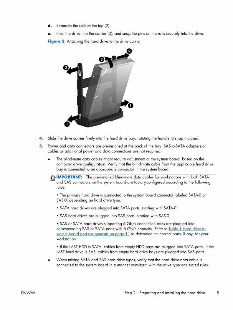
d. Separate the rails at the top (2).
e. Pivot the drive into the carrier (3), and snap the pins on the rails securely into the drive.
Figure 2 Attaching the hard drive to the drive carrier
4. Slide the drive carrier firmly into the hard drive bay, rotating the handle to snap it closed.
5. Power and data connectors are pre-installed at the back of the bay. SAS-to-SATA adapters orcables or additional power and data connections are not required.
● The blind-mate data cables might require adjustment at the system board, based on thecomputer drive configuration. Verify that the blind-mate cable from the applicable hard drivebay is connected to an appropriate connector in the system board.
IMPORTANT: The pre-installed blind-mate data cables for workstations with both SATAand SAS connectors on the system board are factory-configured according to the followingrules:
• The primary hard drive is connected to the system board connector labeled SATA-0 orSAS-0, depending on hard drive type.
• SATA hard drives are plugged into SATA ports, starting with SATA-0.
• SAS hard drives are plugged into SAS ports, starting with SAS-0.
• SAS or SATA hard drives supporting 6 Gb/s connection rates are plugged intocorresponding SAS or SATA ports with 6 Gb/s capacity. Refer to Table 1 Hard drive tosystem board port assignments on page 11 to determine the correct ports, if any, for yourworkstation.
• If the LAST HDD is SATA, cables from empty HDD bays are plugged into SATA ports. If theLAST hard drive is SAS, cables from empty hard drive bays are plugged into SAS ports.
● When mixing SATA and SAS hard drive types, verify that the hard drive data cable isconnected to the system board in a manner consistent with the drive type and stated rules.
ENWW Step 2—Preparing and installing the hard drive 5

Computers with carrier rails that snap onto the hard drive
1. Select an empty hard drive bay.
2. To remove the green rails from the empty bay, squeeze the green tabs and slide the rails out of thebay.
3. To attach the rails to the hard drive:
a. Gently open the rails (1).
b. The connectors on the rear of the drive should face toward the tabs on the carrier rails. Lowerthe drive into the rails (2).
c. Align the four carrier pins with the holes in the hard drive, and snap the rails into place (3).
Figure 3 Installing the hard drive in the rails
4. Push the drive into the bay until it snaps into place.
5. Continue with Step 3—Connecting the power and data cables on page 10.
Computers that use guide screws installed in the hard drive
NOTE: In some computers, such as the HP Z200 SFF or HP Z210 SFF Workstations, you may need totemporarily remove the optical drive to install the hard drive. See the service guide for your workstationat http://www.hp.com/support/manuals.
1. If a card support interferes with access to the system board connectors, remove it.
6 HP SATA/SAS hard drive and Solid State Drive installation ENWW

2. Install four guide screws into the holes near the corners on the sides of the hard drive.
NOTE: Spare guide screws designated for this purpose may be found installed in the sheetmetal of the drive bay structure, or behind the front bezel.
● Some computers, such as the HP Z200, HP Z210 CMT, and HP Z400 series Workstations,use four vibration isolation guide screws (screws with blue grommets).
● Some computers, such as the HP Z200 SFF, Z210 SFF, and xw4000 series Workstations, usefour 6-32 screws.
Figure 4 Installing the guide screws
3. Slide the hard drive into the selected bay until it snaps into place.
4. Continue with Step 3—Connecting the power and data cables on page 10.
Computers that use a DX115 removable hard drive
Some computers have a DX115 unit installed in an optical bay and require that you install a hard drivein the DX115 carrier.
CAUTION: Insert or remove the carrier (with a disk drive) only when the workstation is shut down.Other procedures may result in system hangs, data loss, or even drive damage. The componentsupplier’s user guide describes a procedure for inserting or removing the carrier (with drive) while theworkstation is booted and then powering the drive using the power switch on the enclosure. MicrosoftWindows XP and Windows Vista do not support this action.
To install the hard drive in the carrier:
1. Remove the locking screws from the sides of the carrier.
Figure 5 Removing the locking screws
ENWW Step 2—Preparing and installing the hard drive 7

2. Remove the carrier cover by raising the front end of the cover (1) and pulling it away from the slotin the rear of the carrier (2).
Figure 6 Removing the cover
3. Orient the drive so that the data and power connectors face the rear of the carrier.
4. Place the drive into the front end of the carrier.
5. Slide the drive all the way to the rear end of the carrier so that the power and data connectorsmate with the carrier adapter. Then secure the drive in the carrier with the four locking screwsincluded with the drive.
Figure 7 Installing the drive
8 HP SATA/SAS hard drive and Solid State Drive installation ENWW

6. Replace the cover by aligning the tab on the rear of the cover with the slot on the rear of thecarrier (1) and then rotating the front of the cover onto the carrier (2).
Figure 8 Replacing the cover
7. Replace the locking screws in the sides of the carrier.
Figure 9 Replacing the locking screws
8. With the workstation shut down, insert the carrier into the DX115 unit.
ENWW Step 2—Preparing and installing the hard drive 9

Installing a SATA/SAS/SSD drive into a Western Digital (WD)carrier
1. If installing a 2.5” drive with a SATA or SAS interface into a WD carrier, refer to Figure 1–10.Position the drive in the carrier between the cooling fins and slide it forward so the connector onthe drive aligns with, and plugs into, the carrier's SAS receptacle.
Figure 10 Install the drive into the WD carrier
2. Secure the drive in the WD carrier with the locking screws supplied with the drive (as shown inFigure 1–10).
3. Install the WD carrier into the computer using one of the four drive installation procedurespreviously detailed.
Step 3—Connecting the power and data cablesFollow the instructions for the correct type of drive being installed. SAS drives require installation of anadaptive interface before completing power and data connections.
10 HP SATA/SAS hard drive and Solid State Drive installation ENWW

If installing a SATA drive:
1. Connect the power cable (1) and data cable (2) to the hard drive.
Figure 11 Install power and data cables in SATA drive
CAUTION: Connect the power cable before connecting the data cable to reduce the risk ofdamage to the drive due to Electrostatic Discharge (ESD).
2. Connect the opposite end of the data cable to the system board or SATA/SAS RAID controller PCIcard. Refer to Table 1 Hard drive to system board port assignments on page 11 for the requiredhard drive-to-system board connectors. Start with the primary hard drive connection to the systemboard slot labeled SATA 0.
NOTE: Individual SATA ports and connectors on the system board are identified on the servicelabel, located inside the computer side access panel.
Table 1 Hard drive to system board port assignments
HardDrive
Z200 SFF Z210 SFF Z200 Z210 Z400 Z600 Z800
SATA SATA SATA SATA SATA SATA SAS SATA
1 0 0** 0 0** 0 0 0 0
2 1 1** 1 1** 1 1 1 1
3 2 2 2 2 2 2
4 3 3 3 3
5 4 4
6 5
Asterisks (**) indicate 6 Gb/s transfer rate on that motherboard port.
ENWW Step 3—Connecting the power and data cables 11

If installing a SAS drive:
1. Use the following table to determine the correct adapter and cable configuration for yourworkstation platform. Figure 12 shows examples of adapter types A, B, and C.
Figure 12 Install SAS-to-SATA adapter or cable in SAS drive
Table 2 SAS-to-SATA adapter options
Adaptertype
Platform HDD bay use Cabling with adapter installed
A HP Z400, HPZ600, HPZ800
Internal and opticalHDD bays
Plug in power cable (1) and right angle side of SATA cable (2) intoadapter; plug opposite end (straight angle) of SATA cable intosystem board or SATA/SAS RAID controller PCI card
B HP Z400, HPZ600, HPZ800
Optical HDD baysonly
Plug in power cable (1) and right angle side of SATA cable (2) intoadapter; plug opposite end (straight angle) of SATA cable intosystem board or SATA/SAS RAID controller PCI card
C HP Z400 Internal HDD baysonly
Plug in power cable (1) into four-wire portion of the SAS-to-SATAcable and the SATA data (2) portion of the SAS-to-SATA cable intosystem board or SATA/SAS RAID controller PCI card
12 HP SATA/SAS hard drive and Solid State Drive installation ENWW

2. Connect the power and data cables for your adapter type according to the instructions in Table 2.
Figure 13 Install power and data cables in SAS drive
Step 4—Reassembling the computer1. Reinstall the card support, if applicable.
2. Reinstall the side access panel.
3. Reconnect power to the computer and all external devices.
4. Restore power to the computer and all external devices.
Step 5—Configuring the computerWhen powering up the computer after installation, a new hard drive identifies itself as un-initializedstorage. Consult the operating system documentation for information about how to set up the new drive.
NOTE: Some operating systems such as Microsoft® Windows Vista® automatically scheduledefragmenting sessions. This offers no benefit for an SSD, therefore the user can remove the automaticscheduling. This will also save energy. Go into Control Panel, select Control Panel Home, and thenselect System and Maintenance. In the Administrative Tools area select Defragment your hard drive.Select Select Volumes and then uncheck the box for any SSD disks or volumes.
ENWW Step 4—Reassembling the computer 13

Regulatory noticesThis product has been tested and found to comply with the limits for a Class B digital device of the FCCRules. Refer to the documentation that came with the computer for additional regulatory informationgoverning this product.
Technical supportComprehensive technical support is available online at http://www.hp.com/support.
You can also call HP for technical support. For support telephone numbers, refer to the documentationsupplied with the computer.
Japanese 日本語
This document is available in Japanese. See http://www.hp.com/support/manuals, then select yourproduct and select Japanese from the drop down Manual Language menu.
このドキュメントは日本語版が用意されています。http://www.hp.com/support/manuals にアクセ
スし、ご使用のワークステーション製品を選択し、Manual Language ドロップダウン メニューか
ら Japanese を選択してください。
14 HP SATA/SAS hard drive and Solid State Drive installation ENWW