3ware®9750 sata+sas raid controller card
TRANSCRIPT

3ware®9750 SATA+SAS RAID Controller Card
Version 10.0 Supports 9750-4I and 9750-8I Models
PN: 45412-00, Rev. ANovember 2009
Insta
llati
on
Gu
ide
45412- 00A
Document DescriptionDocument 45412-00, Rev. A, November 2009. This document will remain the official reference source for all revisions and releases of this product until rescinded by an update.
DisclaimerIt is the policy of LSI Corporation to improve products as new technology, components, software, and firmware become available. LSI reserves the right to make changes to any products herein at any time without notice. All features, functions, and operations described herein may not be marketed by LSI in all parts of the world. In some instances, photographs and figures are of equipment prototypes. Therefore, before using this document, consult your LSI representative for information that is applicable and current. LSI DOES NOT ASSUME ANY RESPONSIBILITY OR LIABILITY FOR THE USE OF ANY PRODUCTS DESCRIBED HEREIN EXCEPT AS EXPRESSLY AGREED TO IN WRITING BY LSI.
LSI products are not intended for use in life-support appliances, devices, or systems. Use of any LSI product in such applications without written consent of the appropriate LSI officer is prohibited.
Proprietary Rights NoticeThis document contains proprietary information of LSI Corporation. The information contained herein is not to be used by or disclosed to third parties without the express written permission of an officer of LSI.
License RestrictionThe purchase or use of an LSI Corporation product does not convey a license under any patent, copyright, trademark, or other intellectual property right of LSI or third parties.
ii 3ware 9750 SATA+SAS RAID Controller Card Installation Guide

Copyright Notice© 2009 LSI Corporation. All rights reserved.
Trademark AcknowledgmentsLSI, the LSI logo design, 3ware®, StorSwitch®, and 3DM® are all registered trademarks of LSI Corporation. The StorSave and StreamFusion are all trademarks of LSI. Linux® is a registered trademark of Linus Torvalds in the United States, other countries, or both. Windows® is a registered trademark of Microsoft Corporation in the United States and other countries. SUSE® is a registered trademark of Novell, Inc. Firefox® is a registered trademark of the Mozilla Foundation. Red Hat® is a registered trademark of Red Hat, Inc. PCI Express® is a registered trademark of PCI-SIG®. Safari® is a registered trademark of Apple Inc., registered in the U.S. and other countries. All other brand and product names may be trademarks of their respective companies.
www.lsi.com/channel/products iii
iv 3ware 9750 SATA+SAS RAID Controller Card Installation Guide
About this Guide . . . . . . . . . . . . . . . . . . . . . . . . . . . . . . . . . . . . .v
Chapter 1. Getting Started . . . . . . . . . . . . . . . . . . . . . . . . . . . . . .1Contents of this Package. . . . . . . . . . . . . . . . . . . . . . . . . . . . . . . . . . . . . . 19750 Controller Card Models. . . . . . . . . . . . . . . . . . . . . . . . . . . . . . . . . . . 2Cables . . . . . . . . . . . . . . . . . . . . . . . . . . . . . . . . . . . . . . . . . . . . . . . . . . . . 3
Internal SFF-8087 cable . . . . . . . . . . . . . . . . . . . . . . . . . . . . . . . . . . . . 3System Requirements . . . . . . . . . . . . . . . . . . . . . . . . . . . . . . . . . . . . . . . . 3
Motherboard and Slot Requirements . . . . . . . . . . . . . . . . . . . . . . . . . . 3Enclosure Requirements . . . . . . . . . . . . . . . . . . . . . . . . . . . . . . . . . . . . 4Drive Requirements . . . . . . . . . . . . . . . . . . . . . . . . . . . . . . . . . . . . . . . 4Operating System Requirements . . . . . . . . . . . . . . . . . . . . . . . . . . . . . 4
Safety Information . . . . . . . . . . . . . . . . . . . . . . . . . . . . . . . . . . . . . . . . . . . 6Site Selection . . . . . . . . . . . . . . . . . . . . . . . . . . . . . . . . . . . . . . . . . . . . 6Personal Safety When Installing the 9750 Card in Your Computer . . . 7Protecting Equipment and Data . . . . . . . . . . . . . . . . . . . . . . . . . . . . . . 7Installation Considerations . . . . . . . . . . . . . . . . . . . . . . . . . . . . . . . . . . 8
Chapter 2. Installing the 9750 SATA+SAS Controller Card . . .9Tools You Need . . . . . . . . . . . . . . . . . . . . . . . . . . . . . . . . . . . . . . . . . . . . . 9Before You Start . . . . . . . . . . . . . . . . . . . . . . . . . . . . . . . . . . . . . . . . . . . . 9Install the Controller in the Computer . . . . . . . . . . . . . . . . . . . . . . . . . . . 10Attach the Cables to Your Controller . . . . . . . . . . . . . . . . . . . . . . . . . . . . 12Connect the Cables to Backplanes . . . . . . . . . . . . . . . . . . . . . . . . . . . . . 12Finishing Up the SATA+SAS Controller Card Installation . . . . . . . . . . . . 13
Check Installation and Close the Case . . . . . . . . . . . . . . . . . . . . . . . . 13Configure Your SATA+SAS Arrays . . . . . . . . . . . . . . . . . . . . . . . . . . . . . 14
Chapter 3. 9750 Controller Card Specifications . . . . . . . . . . .15Physical Dimensions . . . . . . . . . . . . . . . . . . . . . . . . . . . . . . . . . . . . . . . . 15Environmental Specification . . . . . . . . . . . . . . . . . . . . . . . . . . . . . . . . . . 16Fault Tolerance . . . . . . . . . . . . . . . . . . . . . . . . . . . . . . . . . . . . . . . . . . . . 17Electrical Characteristics . . . . . . . . . . . . . . . . . . . . . . . . . . . . . . . . . . . . . 18Jumpers and Connectors for the 9750 Controller . . . . . . . . . . . . . . . . . . 19LEDs on 9750 Controller Card . . . . . . . . . . . . . . . . . . . . . . . . . . . . . . . . 21Technical Certifications . . . . . . . . . . . . . . . . . . . . . . . . . . . . . . . . . . . . . . 22
Appendix: Technical Support . . . . . . . . . . . . . . . . . . . . . . . . . .23
Table of Contents

About this GuideCongratulations on your purchase of the 3ware® 9750 SATA+SAS Raid Controller Card. This guide tells you how to install it.
The following additional documentation is available for your 3ware SATA+SAS RAID controller card on the CD that came with your controller. It is also available through the LSI Download Center at http://www.lsi.com/channel/ChannelDownloads.
3ware SATA+SAS RAID Controller Card Software User Guide, Version 10.03ware SATA+SAS RAID Controller Card CLI Guide, Version 10.0
The 3ware HTML Bookshelf is an HTML version of the Software User Guide and the CLI Guide, combined as one resource. It is only available on your 3ware CD, in the /doc/3wareHTMLBookshelf folder.
Online help is also available when you are using 3DM®2 (3ware Disk Manager).
Additional support information is available in the LSI Knowledge Base (eSupport), at https://selfservice.lsi.com/service/main.jsp.
Chapter Description
1 Getting Started Overview of the 3ware SATA+SAS controller card and important safety factors to keep in mind during installation.
2 Installing the 9750 SATA+SAS Controller Card
How to install the 3ware 9750 SATA+SAS controller card.
3 9750 Controller Card Specifications
Specifications for the 9750 controller card.
www.lsi.com/channel/products v

vi 3ware 9750 SATA+SAS RAID Controller Card Installation Guide
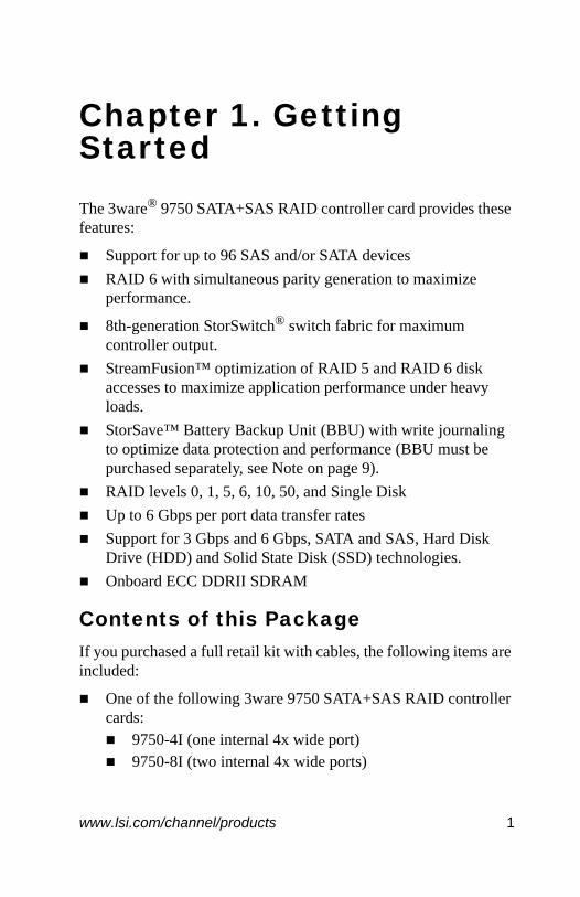
Chapter 1. Getting StartedThe 3ware® 9750 SATA+SAS RAID controller card provides these features:
Support for up to 96 SAS and/or SATA devicesRAID 6 with simultaneous parity generation to maximize performance.
8th-generation StorSwitch® switch fabric for maximum controller output.StreamFusion™ optimization of RAID 5 and RAID 6 disk accesses to maximize application performance under heavy loads.StorSave™ Battery Backup Unit (BBU) with write journaling to optimize data protection and performance (BBU must be purchased separately, see Note on page 9).RAID levels 0, 1, 5, 6, 10, 50, and Single Disk Up to 6 Gbps per port data transfer ratesSupport for 3 Gbps and 6 Gbps, SATA and SAS, Hard Disk Drive (HDD) and Solid State Disk (SSD) technologies.Onboard ECC DDRII SDRAM
Contents of this PackageIf you purchased a full retail kit with cables, the following items are included:
One of the following 3ware 9750 SATA+SAS RAID controller cards:
9750-4I (one internal 4x wide port)9750-8I (two internal 4x wide ports)
www.lsi.com/channel/products 1

Chapter 1. Getting Started
This document, 3ware 9750 SATA+SAS RAID Controller Card Installation Guide3ware CD-ROM with driver, software, and additional documentationAppropriate cables for your 3ware 9750 models.
Model 9750-4I: (one internal 4 lane SATA+SAS cable)Model 9750-8I: (two internal 4 lane SATA+SAS cables)
9750 Controller Card Models Figure 1. Layout of the 4-Port 3ware 9750-4I SATA+SAS RAID
Controller Card
Figure 2. Layout of the 8-Port 3ware 9750-8I SATA+SAS RAID Controller Card
Heat Sink
Connector for Battery Backup Unit
Green LEDCRT4B1
Red LEDCRT6A1
JT5B3JT5B2 JT6B1
JT6B2
JT6B3
for RAID-On-Chip (ROC)
Jumpers
See Table 4 for jumper descriptions and Table 5 for LED descriptions.
Heat Sink
Connector for Battery Backup Unit
Green LEDCRT4B1
Red LEDCRT6A1
JT5B3JT5B2 JT6B1
JT6B2
JT6B3
for RAID-On-Chip (ROC)
Jumpers
See Table 4 for jumper descriptions and Table 5 for LED descriptions.
2 3ware 9750 SATA+SAS RAID Controller Card Installation Guide

Cables
Cables
Internal SFF-8087 cableUse with the internal connectors of the 9750-8I or 9750-4I 3ware RAID controller.
Figure 3. Typical Internal SFF-8087 Cable
System Requirements
Motherboard and Slot RequirementsA workstation-class or server-class motherboard with an x8 or x16 lane PCI-Express Gen 2.0 or 1.0 slot. For a list of supported systems, access the LSI website at http://www.lsi.com/channel/support/marketing_resources, through the Data & Interoperability tab.
Important: You should only use LSI 3ware certified cables with your LSI 3ware RAID controller. Using an incorrect cable can result in drives that are not detected. The appropriate cables are included with your controller. If you must replace a cable, see the list of available cables and associated part numbers at http://www.lsi.com/channel/products/raid_controllers/accessories/cables.
www.lsi.com/channel/products 3

Chapter 1. Getting Started
Enclosure Requirements In order to attach more than four drives per connector, enclosures with expanders are required.
In order to use enclosure support services, such as locating a drive by blinking an LED or notification of a rebuild, the enclosure needs to support SES (SCSI Enclosure Services). For a list of supported chassis and enclosures, access the LSI website at: http:/ www.lsi.com/channel/support/marketing_resources, through the Data & Interoperability tab.
Internal backplane connector: Internal SFF-8087 connector
Drive RequirementsSAS and/or SATA drives can be used with the 3ware 9750 RAID controller.
SATA drives must meet SATA-2 (3.0 Gbps) standards and/or SATA-3 (6.0 Gbps) standards and also be included on the list of supported drives on the interoperability list.
SAS drives must meet SAS (3.0 Gbps and 6.0 Gbps) standards and also be included on the list of supported drives on the interoperability list.
For a list of supported drives, access the LSI website at http://www.lsi.com/channel/support/marketing_resources, through the Data & Interoperability tab.
Operating System Requirements3ware 9750 RAID controller may be used with the following operating systems for Intel and AMD 32-bit and 64-bit x86 based motherboards:
Microsoft Windows Server 2003 (SP-2) and 2008 Microsoft Windows Vista and Windows 7Red Hat Enterprise LinuxopenSUSE Linux
4 3ware 9750 SATA+SAS RAID Controller Card Installation Guide
Safety Information
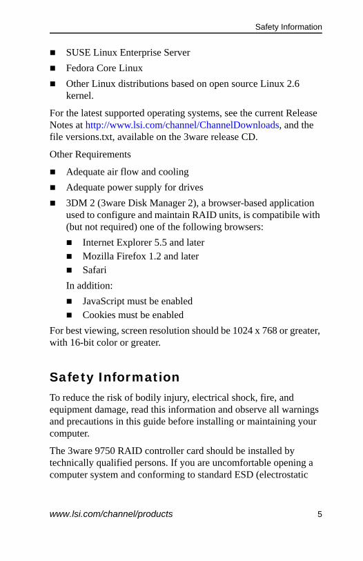
SUSE Linux Enterprise ServerFedora Core LinuxOther Linux distributions based on open source Linux 2.6 kernel.
For the latest supported operating systems, see the current Release Notes at http://www.lsi.com/channel/ChannelDownloads, and the file versions.txt, available on the 3ware release CD.
Other Requirements
Adequate air flow and coolingAdequate power supply for drives3DM 2 (3ware Disk Manager 2), a browser-based application used to configure and maintain RAID units, is compatibile with (but not required) one of the following browsers:
Internet Explorer 5.5 and laterMozilla Firefox 1.2 and laterSafari
In addition:JavaScript must be enabledCookies must be enabled
For best viewing, screen resolution should be 1024 x 768 or greater, with 16-bit color or greater.
Safety Information To reduce the risk of bodily injury, electrical shock, fire, and equipment damage, read this information and observe all warnings and precautions in this guide before installing or maintaining your computer.
The 3ware 9750 RAID controller card should be installed by technically qualified persons. If you are uncomfortable opening a computer system and conforming to standard ESD (electrostatic
www.lsi.com/channel/products 5

Chapter 1. Getting Started
discharge) practices, you should have a computer technician perform the installation.
Site Selection The product is designed to operate as a component to a computer system. The environment that is provided for the system must be:
Clean, dry, and free of airborne particles (other than normal room dust). Well-ventilated and away from sources of heat including direct sunlight and radiators. Away from sources of vibration or physical shock.Isolated from strong electromagnetic fields produced by electrical devices.Provided with a properly grounded wall outlet.Provided a product main power disconnect or sufficient space to access the power supply cord(s), because they serve as the product's main power disconnect.
Personal Safety When Installing the 9750 Card in Your Computer
Warning. We recommend you plug your system into a surge suppressor or UPS (uninterruptible power supply) and during an electrical storm, we recommend disconnecting all phone, network, and power cables.
Warning! High voltages may be found inside computer equipment. Before installing any of the hardware in this package or removing the protective covers of any computer equipment, turn off power switches and disconnect power cords. Do not reconnect the power cords until the hardware is installed and the system cover is closed.
6 3ware 9750 SATA+SAS RAID Controller Card Installation Guide

Safety Information
Protecting Equipment and Data
ESD (Electrostatic Discharge) PrecautionsTo avoid damaging computer components and accessories when installing or removing the 3ware RAID controller card, follow standard electrostatic discharge (ESD) precautions:
When your computer case is open and its internal parts are exposed, do not touch any internal part unnecessarily. Always wear a grounded strap or work on an ESD-protective mat. Do not remove the 3ware SATA+SAS controller card from its protective bag until you are properly grounded. Handle the 3ware RAID controller card by its edges or by the metal bracket.Do not touch any pin, contact, lead or component on the 3ware RAID controller card.
Heat Sink Warning. Do not replace the factory-installed heat sink shipped with the 3ware 9750 SATA+SAS controller cards. Replacing the heat sink will alter thermal characteristics and cooling requirements and may cause the controller to fail. Replacing the factory-installed heat sink will void the warranty.
Back up your data! Creating or deleting disk arrays destroys existing files on the member drives. If your drives contain valuable data, back them up and save the data elsewhere before attaching the drives to the controller.
www.lsi.com/channel/products 7
Chapter 1. Getting Started
Installation Considerations
Air Flow, Cable Length, and Routing Space
Adequate airflow and ventilation are particularly important for 3ware 9750 RAID controller card. The on-board heat sink collects heat, and must have adequate airflow in order to disburse it. It is important that the cables do not obstruct the air flow or prevent proper ventilation of the system.
Selecting the Slot in Which to Install the ControllerConsider these factors when deciding on the slot in which to insert the controller:
3ware 9750 RAID controller card must be installed in PCI Express x8 or x16 slots.
Warning! Do NOT insert the 9750 controller card into a PCI-X slot. Doing so could potentially damage the board or the system, and void the warranty.
Note: Some low-cost motherboards have a single PCI Express slot which is reserved for a video card. These slots cannot accommodate a 3ware 9750 SATA+SAS controller card or other PCI-E device.
Cable routing may be easier if you install the 3ware RAID controller card next to an open slot.
Things to Watch Out For During Installation of the RAID ControllerBe careful when installing the 3ware SATA+SAS controller card into your system. Excessive force can damage the board or your system.
Be sure to follow the installation instructions in “Chapter 2. Installing the 9750 SATA+SAS Controller Card” on page 9.
Warning. Do not operate the 9750 controller card with system cover removed, as this may disrupt proper airflow.
8 3ware 9750 SATA+SAS RAID Controller Card Installation Guide

Tools You Need
Chapter 2. Installing the 9750 SATA+SAS Controller Card
Tools You NeedYou will need the following tools during installation:
An ESD grounding strap or matA Phillips screwdriver
Before You Start3ware 9750 SATA+SAS controller cards can be installed in a standard enclosure or in an enclosure with a backplane.
1 Be sure to read “Safety Information” on page 5 in Chapter 1.2 If you have a Battery Backup Unit (BBU), install it before
proceeding.
3 If your enclosure is low-profile, unscrew the full height bracket from the 3ware 9750 SATA+SAS controller card and replace it with the included low-profile bracket, using the same screws.
4 If appropriate, set the PM2 (power management) jumper on the disk drives, to enable staggered spinup. Check the
Note – For more information about installing the BBU directly to the 9750 Controller, refer to the LSI document, “MegaRAID iBBU07 Intelligent Battery Backup Unit Quick Installation Guide ”. Use the search feature located at: http://www.lsi.com/channel/ChannelDownloads, to find the referenced LSI document. Search for iBBU07, click on the link for the iBBU07 Quick Installation Guide (QIC).
The remote mounting option mentioned in the BBU installation Guide is not supported on the 9750 controller card.
www.lsi.com/channel/products 9

Chapter 2. Installing the 9750 SATA+SAS Controller Card
documentation that came with your disk drives to see whether this is required.
5 SATA-2 hard drives are sometimes shipped from the manufacturer with the transfer rate set to 1.5 Gbps. If this is the case for your drives, you may need to remove a jumper or run a software utility to change the transfer rate to 3.0 Gbps. Please check with your hard drive manufacturers documentation or website on how to set the transfer rate to 3.0 Gbps.
Install the Controller in the Computer1 If the computer is running, shut it down. Turn off power to the
computer and disconnect the power cord from the outlet.
2 Make sure you are properly grounded. (For details about ESD precautions, see page 7.)
3 Open the computer case according to the manufacturer’s instructions.
4 Locate the PCI Express slot you want to use for the 3ware 9750 SATA+SAS controller card.
For a discussion of which slot to use, see “Selecting the Slot in Which to Install the Controller” on page 8.
5 Remove the metal filler bracket for the slot.
Save this screw; it will be used to secure the 3ware 9750 SATA+SAS controller after you have seated it in the slot.
6 Position the card in the PCI Express slot so that the contacts will mate with the grooves in the slot, and all pins make proper contact with the PCI Express slot pins when pushed into place.
7 Press down gently on the edge of the 3ware RAID controller directly above the PCI Express slot until it is fully seated.
10 3ware 9750 SATA+SAS RAID Controller Card Installation Guide

Install the Controller in the Computer
Figure 4. Inserting Controller Into PCI Express Slot
8 Check that the 3ware SATA+SAS controller’s metal bracket covers the hole in the case and secure the bracket with the screw that was used to secure the filler bracket in step 5.
Warning! Make sure you select a PCI Express (PCI-e) slot, not a PCI or PCI-X slot, see Figure 4. Inserting a 9750 into a PCI or PCI-X slot could potentially damage the board or system, and void the warranty of either the 9750 or the motherboard. If you are uncertain about which slot to use, see the documentation for your system’s motherboard.
Note: The configuration of the enclosure may not be the same as shown Figure 4.
PCI slot DO NOT USE
PCI-X slot DO NOT USE
www.lsi.com/channel/products 11
Chapter 2. Installing the 9750 SATA+SAS Controller Card
9 When you tighten the screw on the bracket to the enclosure, make sure the card is not slanted in any direction; otherwise the card will not work properly.
Attach the Cables to Your Controller
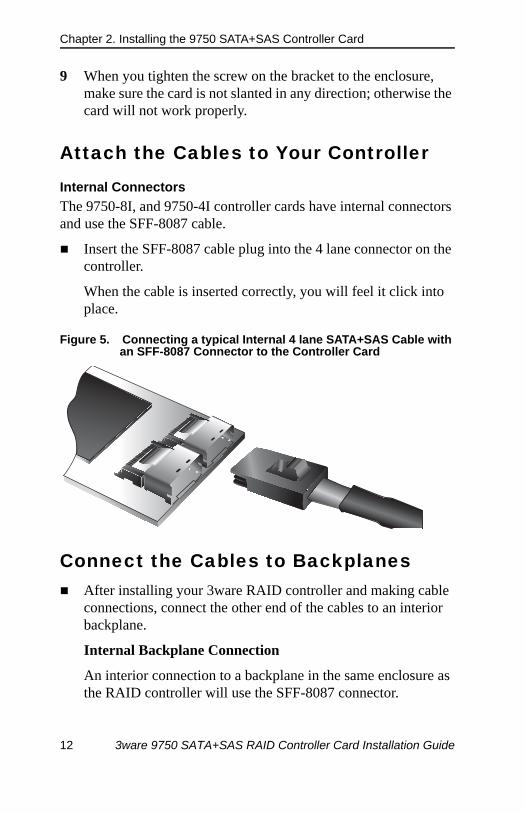
Internal ConnectorsThe 9750-8I, and 9750-4I controller cards have internal connectors and use the SFF-8087 cable.
Insert the SFF-8087 cable plug into the 4 lane connector on the controller.
When the cable is inserted correctly, you will feel it click into place.
Figure 5. Connecting a typical Internal 4 lane SATA+SAS Cable with an SFF-8087 Connector to the Controller Card
Connect the Cables to BackplanesAfter installing your 3ware RAID controller and making cable connections, connect the other end of the cables to an interior backplane.
Internal Backplane Connection
An interior connection to a backplane in the same enclosure as the RAID controller will use the SFF-8087 connector.
12 3ware 9750 SATA+SAS RAID Controller Card Installation Guide

Finishing Up the SATA+SAS Controller Card Installation
Connect the other end of the SFF-8078 multi-lane cable to the connector on the backplane.
Figure 6. Connecting the Controller to the Backplane
Finishing Up the SATA+SAS Controller Card InstallationAfter you have installed the controller in the computer and attached appropriate cables to the controller and drives, complete the following steps to complete the hardware installation.
Check Installation and Close the Case1 Verify that the cables do not interfere with the operation of any
other components in the case or block the flow of cooling air.2 Close the case and reconnect the power cables.
Note: If your backplane has individual connections for each drive, or if you do not have a backplane, you can directly connect up to 4 drives per internal connector through use of a breakout cable.
Note: Figure 6 is for reference only. System connection may not be the same as shown in this illustration.
Backplane
SFF-8087Connector
MotherboardPCI-e slot
Chassis
9750 Controller Card
8087 Multi-lane Cable
www.lsi.com/channel/products 13

Chapter 2. Installing the 9750 SATA+SAS Controller Card
Configure Your SATA+SAS ArraysTurn to “First Time RAID Configuration” and “Configuring Units” in 3ware SAS/SATA RAID Controller Card Software User Guide, Version 10.0 for information about configuring RAID arrays. The user guide is included on the 3ware CD that came with your controller. It is also available from the LSI website at: http://www.lsi.com/channel/ChannelDownloads.
14 3ware 9750 SATA+SAS RAID Controller Card Installation Guide
Physical Dimensions
Chapter 3. 9750 Controller Card Specifications
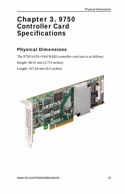
Physical DimensionsThe 9750 SATA+SAS RAID controller card size is as follows:
Height: 68.91 mm (2.713 inches)
Length: 167.64 mm (6.6 inches)
www.lsi.com/channel/products 15

Chapter 3. 9750 Controller Card Specifications
Environmental Specification The 9750 SATA+SAS RAID Controller card environmental requirements are listed in Table 1.
Table 1: Controller Environmental Specification
Specification Operating Non-Operating
Temperature +10°C to +60 °C without optional battery backup unit 0°C to +40 °C with optional battery backup unit
-30°C to +80 °C without optional battery backup unit0°C to +45 °C with optional battery backup unit
Humidity 5% to 90% RH, noncondensing, 40 °C max, 27 °C max wet bulb, 16 hour dwells at extreme
93% RH, noncondensing, 40 °C max, 120 hours
Altitude 3200 m at 40 °C, 4 hour dwell
12,200 m at 0°C, 4 hour dwell
Vibration 0.25 G in all axes swept for 5-500-5 Hz, 5 sweeps in all at 1 octave/min
1.2 G in all axes swept for 5-500-5 Hz, 5 sweeps in all at 1 octave/min
Shock 5.5 G, 11 ms half-sine, 10± shocks in x-, y-, and z-axes
33 G, 11 ms half-sine, 3± shocks in x-, y-, and z-axes
Airflow At least 200 linear feet per minute (LFPM)
N/A
Caution! Do not operate the 9750 Controller Card at any time without proper cooling.
16 3ware 9750 SATA+SAS RAID Controller Card Installation Guide

Fault Tolerance
Fault ToleranceTable 2 lists the fault tolerance features for the 9750 RAID controller.
Table 2: Fault Tolerance Features
Specification 9750 RAID Controller
Support for SMART1
1. The Self Monitoring Analysis and Reporting Technology (SMART) detects up to 70 percent of all predictable drive failures. In addition, SMART monitors the internal performance of all motors, heads, and drive electronics.
Yes
Optional battery backup unit for cache memory
Optional LSI iBBU07 battery backup unit. < 3.7 V/1350 mAH battery pack; up to 72 hours of data retention for 512 Mbytes
Drive failure detection Automatic
Drive rebuild using hot spares Automatic
Parity generation and checking
Yes
RAID Levels 1, 5, 6, 10, 50 Yes
www.lsi.com/channel/products 17

Chapter 3. 9750 Controller Card Specifications
Electrical CharacteristicsAll power is supplied to the controller through the PCI Express 3.3 V rails and the 12 V rail. Onboard switching regulator circuitry operating from the 3.3 V rails and the 12 V rail provide the necessary voltages. The following states determine the typical current consumption of the 9750 controller card:
State 1: During a hard resetState 2: During a disk stress testState 3: While sitting idle at the DOS prompt
The supply voltages are 12 V ± 8 percent (from PCI edge connector only) and 3.3 V ± 9 percent (from PCI edge connector only). Table 3 lists the power supply for the controller for each of the three states at the different voltages.
+12 V is used in the charging circuitry for the optional battery pack on the optional iBBU battery-backed daughter card. If the iBBU daughter card is mounted, the following power consumption figures apply: During fast charging of the battery pack: 230 mA rise in +12 V supply current.
Table 3: Power Supply for the 9750 Controller
PCI Edge Connector State 1 State 2 State 3
3.3 V supply 330 mA 330 mA 330 mA
12 V supply 1.00 A 1.81 A 1.53 A
3.3 V auxiliary supply 30 mA 30 mA 30 mA
18 3ware 9750 SATA+SAS RAID Controller Card Installation Guide
Jumpers and Connectors for the 9750 Controller
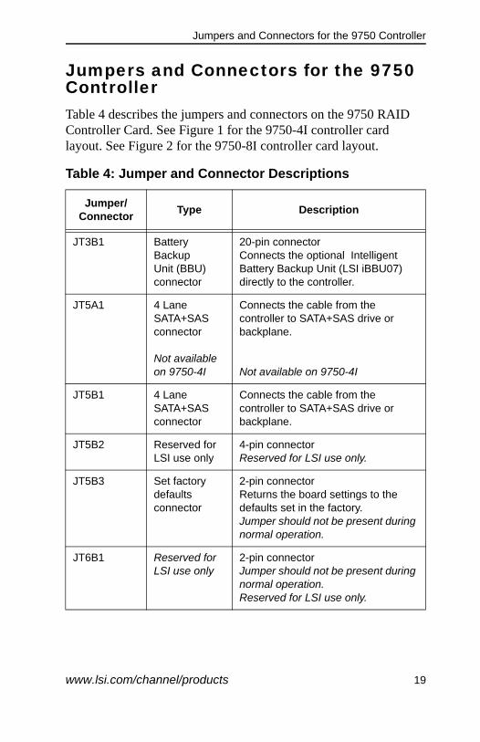
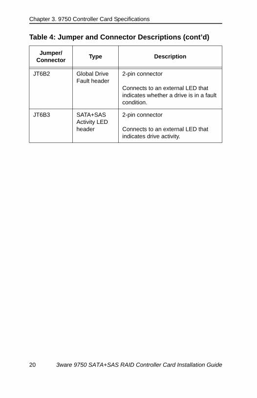
Jumpers and Connectors for the 9750 ControllerTable 4 describes the jumpers and connectors on the 9750 RAID Controller Card. See Figure 1 for the 9750-4I controller card layout. See Figure 2 for the 9750-8I controller card layout.
Table 4: Jumper and Connector Descriptions
Jumper/Connector Type Description
JT3B1 Battery BackupUnit (BBU) connector
20-pin connectorConnects the optional Intelligent Battery Backup Unit (LSI iBBU07) directly to the controller.
JT5A1 4 Lane SATA+SAS connector
Not available on 9750-4I
Connects the cable from the controller to SATA+SAS drive or backplane.
Not available on 9750-4I
JT5B1 4 Lane SATA+SAS connector
Connects the cable from the controller to SATA+SAS drive or backplane.
JT5B2 Reserved for LSI use only
4-pin connectorReserved for LSI use only.
JT5B3 Set factory defaults connector
2-pin connectorReturns the board settings to the defaults set in the factory. Jumper should not be present during normal operation.
JT6B1 Reserved for LSI use only
2-pin connectorJumper should not be present during normal operation.Reserved for LSI use only.
www.lsi.com/channel/products 19
Chapter 3. 9750 Controller Card Specifications
JT6B2 Global Drive Fault header
2-pin connector
Connects to an external LED that indicates whether a drive is in a fault condition.
JT6B3 SATA+SAS Activity LED header
2-pin connector
Connects to an external LED that indicates drive activity.
Table 4: Jumper and Connector Descriptions (cont’d)
Jumper/Connector Type Description
20 3ware 9750 SATA+SAS RAID Controller Card Installation Guide

LEDs on 9750 Controller Card
LEDs on 9750 Controller CardThe 9750 SATA+SAS RAID Controller Card has two LEDs that are visible. Figure 7 shows the internal connectors and LEDs.
Figure 7. 9750-8I Internal Connectors and LEDs
The different states of the LEDs are listed in Table 5.
Table 5: Red LED and Green LED States
State Meaning
Green LED (CRT4B1)1
1. LED only blinks green when there are drives attached and data is being read or written.
Indicates LSISAS2108 RAID-on-chip (ROC) ASIC is operating normally
Off The ROC ASIC is not operating normally.
On1 The ROC ASIC is operating normally.
Red LED (CRT6A1)
Error status signal
Off Indicates that there is no system error.
On Indicates that there is a system error.
Heat Sink
Connector for Battery Backup Unit
Green LEDCRT4B1
Red LEDCRT6A1
JT5B3JT5B2 JT6B1
JT6B2
JT6B3
for RAID-On-Chip (ROC)
Jumpers
www.lsi.com/channel/products 21

Chapter 3. 9750 Controller Card Specifications
Technical CertificationsThe design and implementation of the 3ware 9750 SATA+SAS RAID controller card minimize electromagnetic emissions, susceptibility to radio frequency energy, and the effects of electrostatic discharge. The 9750 SATA+SAS RAID controller show the following marks and certifications:
CE markC-Tick markFCC Self-Certification logoCanadian Compliance StatementKorean MICTaiwan BSMIJapan VCCICISPR Class B
The following hardware is compliant with CSA C22.2 No.60950-1, UL 60950-1 First Edition-listed accessory, Agency model # 25239
3ware 9750-8I SATA+SAS RAID Controller Card 3ware 9750-4I SATA+SAS RAID Controller Card
22 3ware 9750 SATA+SAS RAID Controller Card Installation Guide
www.lsi.com/channel/products 23
Appendix: Technical SupportFor support, troubleshooting tips, frequently asked questions, software releases, and compatibility information related to LSI 3ware RAID controllers, refer to:
LSI 3ware support page at: http://www.lsi.com/channel/support.LSI 3ware Knowledge Base (eSupport), at: https://selfservice.lsi.com/service/main.jsp. LSI 3ware software downloads, at: http://www.lsi.com/channel/ChannelDownloads.LSI 3ware documentation, at: http://www.lsi.com/channel/ChannelDownloads.LSI 3ware compatibility lists, at: http://www.lsi.com/channel/support/marketing_resources.
LSI offers 24 hour/7 days a week phone tech support.
North America: 800-633-4545International: 00-800-5745-6442 The International phone number does not require country specific access codes.
If you have a question regarding technical support, sales support, the LSI Reseller Partner Program or anything else, simply fill in the form at http://www.lsi.com/channel/ContactUs, and the appropriate contact will get back to you as soon as possible.