hp archivehparchive.com/manuals/hp-456a-manual.pdf · operating and servicing manual model 456a...
TRANSCRIPT

HP Archive
This vintage Hewlett Packard document was preserved and distributed by
www. hparchive.com
Please visit us on the web !
Thanks to on-line curator: Kenneth Kuhn for supplying and scanning this vintage document.

5 A C CURRENT P R O B E
SERIALS PREFIXED: 103-
O P E R A T I N G A N D S E R V I C I N G M A N U A L
, PRINTED 3/61
00395-1

OPERATING AND SERVICING MANUAL
MODEL 4 5 6 A SERIALS PREFIXED: 103 -
A C C U R R E N T P R O B E
H E W L E T T - P A C K A R D C O M P A N Y Mall R O A D . P&Lo ALIO. C A L I F O R N I A ,
1961 ". I .* .
00395.1 Printed: MAR 1961

Model 456A Table of Contents List of Illustrations and Tables
TABLE OF CONTENTS
Section Title Page
I GENERAL INFORMATION . . . . . . . . . 1-1
1-1 . General Description . . . . . . . . . 1-1
1.2 . Power Requirements . . . . . . . . . 1-2
I1 OPERATING INSTRUCTIONS . . . . . . . 2-1
2.1 . General . . . . . . . . . . . . . . . . 2-1
2.2 . Operating Instructions . . . . . . . . 2-1
2.3 . Operating the Probe . . . . . . . . . 2-1
2.4 . Increasing the Sensitivity . . . . . . 2-1
2.5 . Measurement Precautions . . . . . 2-1
2-6 . Special Measuring Techniques . . . 2-4
Ill THEORY OF OPERATION . . . . . . . . . 3-1
3.1 . Introduction . . . . . . . . . . . . . 3-1
3.2 . Probe Head . . . . . . . . . . . . . 3-1
3.3 . Amplifier . . . . . . . . . . . . . . 3-1
Section Title Page
IV MAINTENANCE . . . . . . . . . . . . . . . 4-1
4.1 . General . . . . . . . . . . . . . . . . 4-1 4.2 . Cabinet Removal . . . . . . . . . . . 4-1
4.3 . Operation on 230 Volt AC . . . . . . 4-1
4.4 . Checking the Batteries . . . . . . . . 4-1
4.5 . Replacing the Batteries . . . . . . . 4-1
4.6 . Converting to AC-Operated Model . . 4-3 4.7 . Test Equipment Required . . . . . . . 4-3
4.8 . Front Panel Performance Check . . 4-3
4.9 . Trouble Localization . . . . . . . . . 4-3
4.10 . Semi-Conductor Replacement . . . . 4-4
4.11 . Calibration . . . . . . . . . . . . . . 4-4 4.12 . Frequency Response . . . . . . . . 4-4
4.13 . Replacing the Probe Cable . . . . . 4-4
V REPLACEABLE PARTS . . . . . . . . . . 5-1
5.1 . Introduction . . . . . . . . . . . . . . 5-1 5.2 . Table of Replaceable Par t s . . . . . 5-1
5.3 . Ordering Information . . . . . . . . 5-1
LIST OF ILLUSTRATIONS
Number Title Page Number Title Page
1.1 . 1.2 . 1.3 .
2.1 . 2.2 . 2.3 . 2.4 .
2.5 .
General Arrangement of Model 456A . . 1-1 2.6 . Model 456A AC Current Probe . . . . . . Typical Change in Frequency Response
1-1
with Load Capacitance . . . . . . . . . 1-2 3.1 . 3.2 .
Probe used with @ Model 302A . . . . . 2-1
Cleaning Probe Jaws . . . . . . . . . . . 2-3
. . . . . . . . . . . . . . . . . 4.1 . 4.2 . 4.3 . Ground Loops 2-3
Current Measurement . . . . . . . . . 2-4 4.4 .
Operation 2-2
Illustrating Development of
Illustrating Directional Effect of . . . . . . . . . . . . .
Bucking Out Capacitive Component of Plate Current . . . . . . . . . . . . 2-5
Equivalent Circuit . . . . . . . . . . . . 3-1
Feedback Circuit . . . . . . . . . . . . . 3-1
Servicing Etched Circuit Boards . . . . . 4-0
4-2
4-5
4-6
Calibration and Frequency Response . . . Exploded View of Probe Assembly . . . . Schematic Diagram Model 456A . . . . .
LIST OF TABLES
Number Title Page Number Title Page
4.1 . Replacement . . . . . . . . . . . . . . . 4-4
5.1 . Replaceable Par t s . . . . . . . . . . . . 5-2
1.1 . Specifications . . . . . . . . . . . . . . . 1-0
1.2 . Instruments for use with 456A . . . . 1-1
00395-1 iii

Section I Table 1-1
Table 1-1. Specifications
Model 456A
SENSITIVITY
FREQUENCY RESPONSE:
PULSE RESPONSE:
MAXIMUM INPUT:
EFFECT OF DC CURRENT:
INPUT IMPEDANCE:
PROBE SHUNT CAPACITY
DISTORTION A T 1 KC:
EQUIVALENT INPUT NOISE:
OUTPUT IMPEDANCE:
POWER:
WEIGHT:
DIMENSIONS:
ACCESSORY AVAILABLE:
1 ma/ma f 1% at 1 kc
*2%. 100 Cps to 3 mc; +5%, 60 cps to 4 mc; -3 dh at 25 cps and greater than 20 mc.
Rise time is less than 20 nanoseconds, sag is less than 16% per milli- second.
1 amp rms; 1.5 amp peak. 100 ma above 5 mc.
No appreciable effect on sensitivity and distortion from dc current up to 0.5 amp.
(Impedance added in series with measured wire by probe.) Less than 50 milliohms in series with 0.05 ph. (This is approximately the induc- tance of 1-1/2 inches of hookup wire.)
Approximately 4 pf added from w i r e to ground.
For 1/2 amp input at least SO db down. For 10 ma input at least 70 db down.
Less than 50 pa rms (100 pa when ac powered).
220 ohms at 1 kc. Approximately +1 volt dc component. Should work into load of not less than 100,000 ohms shunted by approximately 25 pf.
Two Mallory Battery CO. TR 233R and one TR 234 batteries stock # 1420-0005 and 1420-0006), battery life is approximately 400 hours. AC power supply optional at extra cost, 115/230 volts +lo%, 50 to 1000 cps, approximately 1 watt.
Net 3 Ibs.
5 in. wide, 6 in. deep, 1-1/2 in. high. Probe cable is 5 f t long, output cable is 2 ft long and terminated with a dual banana plug.
456A-95B AC Supply for field installation.
1-0 00395-1

Model 456A Section 1 Paragraph 1-1
S E C T I O N I
G E N E R A L I N F O R M A T I O N
1-1. GENERAL DESCRIPTION.
The Model 456A is an instrument for measuring ac current. I t consists of a probe and amplifier, and is used together with an associated voltmeter or oscil- loscope (see figure 1-1).
I ,Conductor measured
Figure 1-1. General Arrangement of Model 456A
Current is measured by merely clamping the probe of the Model 456A around the current carrying conductor.
The probe operates with an accompanying small ampli- fier to convert the ac current beingmeasured to a pro- portional voltage. The current-to-voltage conversion factor is 1 millivolt output for 1 milliampere flowing through the probe. Current readings can thus he taken directly from the voltage calibrations on the voltmeter or oscilloscope. Table 1-2 is a list of instruments which can be used with the probe.
Table 1-2. Instruments for use with 456A AC Current Probe
Voltmeters
400D 400H 400L 403A
Wave Analyzer 302A
Oscilloscopes
120A 122A 130B 150A 1608 170A
Figure 1-2. Model 456A AC Current Probe
1-1 00395-1

Section 1 Paragraph 1-2
For flat frequency response the shunt input impedance of the associated voltmeter or oscilloscope should be greater than l00K ohms in parallel with 25 pf o r made to appear that value to the 456A.
Lower shunt resistance will change the accuracy equally at all frequencies, due to the low output im- pedance (about 200 ohms) of the Model 456A.
Different shunt capacitances have no effect on the low frequency response, but can affect the high frequency gain as shown in figure 1-3.
Model 456A
-6 1 MC 10 MC 30 MC
Figure 1-3. Typical Change in Frequency Response with Load Capacitance
The Model 456A output contains a dc component of approximately + 1 vdc which must not be loaded ex- cessively (less than 10Kohms shunt load is excessive). Almost all ac voltmeters and oscilloscopes have a dc blocking capacitor in the input circuit to take care
1-2
of this requirement. DO NOT USE THIS INSTRU- MENT WITH RECTIFIER TYPE METERS. The loading in this type of instrument is excessive and may affect the reading.
1-2. P O W E R REQUIREMENTS.
The Model 456A is available either a s a battery powered or ac powered instrument. The AC Power Supply(@ stock #456A-95B) fits into the space nor- mally occupied by the battery supply and takes the place of it electrically. The ac power supply must he ordered separately.
When the 456A is powered with its own internal bat- teries i t is independent of power lines. It may be used in the field with battery operated voltmeters, such a s the Model 403A AC Voltmeter, or battery powered oscilloscopes. Battery operation is also useful in the laboratory where complete isolation is desired. While battery operated the 456A may be used with the chassis off ground without difficulty. This type of operation may also be desired to isolate power line hum in a system where several instru- ments a r e used.
When the 456A is used with the a c power supply the chassis is automatically grounded through the third prong in the power plug. The three conductor power cable supplied with the instrument i s terminated in a polarized, three-prong male connector recommended by the National Electrical Manufacturers’ Association (NEMA). The third conductor grounds the instrument chassis for protection of the operating personnel.
WARNING When using a three-prong to two-prong adapter ground the third lead (green wire) externally.
00395-1

Model 456A Section 11 Paragraphs 2-2 to 2-5
S E C T I O N II
O P E R A T I N G I N S T R U C T I O N S
2-1. GENERAL. The Model 456A must be used with an ac voltmeter or an oscilloscope. Figure 2-2 shows a typical setup.
2-2. O P E R A T I N G I N S T R U C T I O N S .
Connect the shielded plug of the Model 456A OUTPUT cable to a voltmeter o r oscilloscope of appropriate range. The conversion ratio is millivolts out equals milliamperes in. Thus the voltmeter should read in millivolts the expected milliamperes being measured. The current range of the Model 456A is less than 1 milliampere to 1 ampere. The Model 400D/H/L Vacuum Tube Voltmeter is ideal for this measurement a s i t covers the entire range and has a 3/4 inch spac- ing input jack.
WARNING DO NOT PLUG THE OUTPUT CABLE OF THE 456A lNTO A SOURCE OF AC OR DC VOLTAGE. Doing so will burn out the tran- sistors and perhaps other components.
The spacing of the pins on the OUTPUT cable fits all standard 3/4 inch connectors, such as on Hewlett- Packard voltmeters, wave-analyzers, and oscillo- scopes (when used with AC-76A adapter). See table 1-2 for a list of Hewlett-Packard instruments suitable for use with the Model 456A.
The Model 400D has an additional output terminal for viewing the voltage being measured with an oscil- loscope. This may be very useful, for example, measuring the current at which a transistor starts clipping.
The Model 456A may be used to measure very low current, even below the noise level of the probe, if some provision is made to filter out the noise. The
Model 302A Wave Analyzer is ideal for this purpose, particularly if the BFO of the 302A is used a s the signal source (see figure 2-1).
Transistor under test -hp- 302A WAVE ANALYZER
BFO OUTPUT - h p - 456A 20 -50KC
CURRENT PROBE
Figure 2-1. Probe can he used with 302A to measure distortion in current waveforms
o r to measure small audio current, as described in text
00395-1
In this manner, currents even below 10 microamperes can be measured.
2-3. O P E R A T I N G THE PROBE.
The probe jaws may be operated withonehand. While holding the probe handle in the palm, squeeze the flanges together with the fingers. This action wil l open the jaws. Move the probe to the vicinity of the insulated wire being measured and slowly release the flanges until the jaws fit over the wire.
CAUTION Do NOT let the jaws snap closed as they may he damaged.
Clip the probe over the wire with the arrow on the probe in the direction of conventional current flow for a positive-going output signal. This procedure is important when using an oscilloscope but it may also be important when using this probe tomeasure unsym- metrical waveforms with half-wave rect i f ier type meters. All Hewlett-Packard meters listed in table are full-wave rectifier types so you wil l get the same reading whichever way the probe is clipped over the wire. However, with half-wave type meters the readings may be different. This action is a limi- tation of the meter and not a fault of the Model 456A. Refer to the Operating and Servicing Manual for the meter o r change to one of the recommended meters.
2-4. I N C R E A S I N G THE SENSITIVITY.
Sensitivity of the Model 456A may be increased by looping the wire carrying the current to be measured through the jaws more than once. The reading on the meter or oscilloscope wil l he multiplied by the number of times that the current passes through the jaws. To obtain the true reading divide the current indication by the number of turns enclosed by the jaws. The series loading effect of the probe on the circuit being measured is then multiplied by the square of the number of turns. This effect may have to be taken into account (see paragraph 2-5D).
2-5. MEASUREMENT PRECAUTIONS.
Best performance will be achieved by observing the following precautions:
A. PROBE HANDLlNG
1) Do not snap the jaws closed by letting go of the probe flanges abruptly. This action may damage the shield o r the jaws.
2) Do not drop the probe. The jaws a re made from an
2-1

Section 11 Figure 2-2
Model 456A
INSULATED CONDUCTOR
BEING MEASURE0
1. Connect output of 456A to a voltmeter or oscil- loscope.
2. Clip probe around wire under test (open jaws by squeezing flanges on probe together).
3. Connect ground-clip to instrument under test, if necessary (see paragraph 2-5E).
4. Read current being measuredon meter o r oscil- loscope (read millivolts a s milliamperes).
5 . Note direction of arrow on probe. Conventional current flow in direction of arrow gives positive going output voltage.
Figure 2-2. Operation
2-2 00395-1

Model 456A Section 11 Paragraph 2-5 (Cont’d)
Figure 2-3. Cleaning Probe Jaws
alkyd material which is very durable in normal use, but is not made to withstand the shock of dropping.
3) Keep the probe jaws clean. If the jaws appear dirty or if the low frequency responsedropsoff, clean the jaws as shown in figure 2-3 using carbon tetra- chloride and the brush provided or, in extrerne cases, a pencil eraser.
The probe jaws should mate perfectly with no a i r gap between the ferrite pole pieces. Foreign matter (dirt specks, wax from capacitors, sand particles, pieces of insulating tape etc.) may hold the pole pieces from closing perfectly. Normally the only effect will he to lower the gain at low frequencies (below 10 kc). Even a s small an a i r gap as 0.0005 inch will lower the gain significantly at low frequencies.
4) Always clip the probe around insulated wire. If you must measure the current in a bare wire, f i r s t insulate the wi re with tape or insulating tubing.
5) Do not expose the probe to high temperatures. Exposure to temperatures above 55oC is not recom- mended.
B. DlRECT CURRENT IN THE SIGNAL BElNG Direct current in the signal being
measured should preferably be kept below 1/2 ampere. Direct current below that value will have no effect on the measurement.
MEASURED.
C. ALTERNATING CURRENT FIELDS. The probe is shielded against external ac magnetic and
electric fields. Extremely strong fields may cause an erroneous reading. If a strong ac magnetic field
00395-1
is suspected, rotate the empty probe head with the jaws closed. If the reading changes, an ac field is affecting the probe.
D. GROUND LOOPS. With the a c supply avoid ground loops i n test setups, such a s those produced
between the third prong on the ac cable and the ground on the indicating instrument. An easy method of test- ing for ground loops is to clip the probe over the 456A output cable. Any reading indicates the presence of ground loops.
OTHER EQUIPMENT SET-UP BEING TESTED
POWER I I L I N E S
I_-- -- * POWER LINE
Figure 2-4. Illustrating Development of Ground Loops
Referring to figure 2-4, note that the leakage current I-leakage causes a voltage drop across the groundlead resistance This appears a s a voltage, in ad- dition to the signal voltage, between the ac current probe Z1 and the indicating device Z2. An easy way of minimizing this problem is to connect both instru- ments to the same ac receptacle. Another method is to use a battery-powered Model 456A.
2-3

Section II Paragraph 2-6
E. EFFECT OF PROBE ON CIRCUlT BEING MEASURED. The probe adds an inductance of
less than 0.05 microhenries to the circuit under test. With almost all conditions this small an inductance will not affect the measurement.
Model 456A
However, i f the measurement is made in a very low capacitance and very high impedance circuit, with high ac voltages, and at high frequencies, the shunt capacitance of the probe to ground must be taken into consideration. A capacitance is added from the meas- ured wire to the grounded shieldinside the 456A probe when the probe is clamped around the wire. This capacitance typically has a value anywhere from 1 pf to 5 pf, depending upon wire size, insulation and location within the probe aperture. This capacitance has two effects:
1) The measured wire is slightly “loaded” with a capacitance to ground of around 3 pf.
2) The capacitive current which flows to ground through this wire-to-probe capacitance can be meas- ured by the probe, although it almost always adds a negligible amount to the reading of the actual cur- rent in the wire.
To test if this effect should he considered, solder one end of a short, stiff, piece of insulated wire to the circuit at the point where the measurement is to be made. Leave the other end of this wire unconnected. This wire wil l have voltage on it but no current through it. Clip the probe over this wire and read the meter. Reverse the direction that the probe is clipped on the wire (point arrow on probe in other direction) and read meter again. If there is no reading on the meter in either of these positions the probe capacitance has no effect. If there is a reading proceed to the next paragraph.
The shunt capacitance introduced by the probe is 1 to 5 pf (typically 3 pf). Assuming the worst case of 5 pf, a maximum e r r o r current of:
I = 0.03 ma X volts X megacycles
can flow through the 5 pf to ground. That i s , a 1 mc voltage of 1 volt impressed across this shunt capaci- tance will cause a reading of only 0.03 ma by the 456A. However, at higher frequencies the effect will increase proportionally.
Even with this effect you may choose which side of the circuit to measure the current. See figure 2-5.
Note in figure 2-5 the probe measures the current flowing i n the circuit on the same side as the wide side of the arrow on the probe.
Occasionally at high frequencies (above 15 mc) a greatly magnified voltage effect exists at a particular frequency. This effect is caused by a resonance be- tween excessive external ground lead lengths and stray capacities. The following steps a r e suggested to eliminate this type of problem:
2-4
THE PROBE AND WIRE BEING MEASURED HAS AN EQUIVALENT CIRCUIT OF:
THIS CURRENT THIS CURRENT I’ NOT MEASURED MEASURED
/- I
\ \
\ \ I To 5pF
RO
PROBE MEASURES CURRENT IN CIRCUIT O N THE SAME SIDE OF PROBE AS SIDE OF ARROW,
Figure 2-5. Illustrating Directional Effect of Current Measurement
1) Ground oscilloscope or voltmeter to equipment ground with as short leads as possible.
2) Connect special resistive ground lead (supplied) to the closest ground to theconductor being measured. ,
4) Ground 456A to oscilloscope or voltmeter with a standard (non-resistive) short clip lead (not furnished).
2-6. SPECIAL M E A S U R I N G TECHNIQUES.
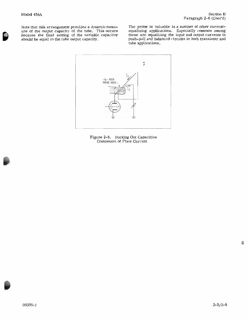
Since the probe is effectively a current transformer, it has the property that it will algebraically sum the instantaneous value of the currents in two or more conductors it may be clipped around. This property makes the probe a valuable and easily-applied tool in applications in which it is desired to equalize or balance ac currents. For example, in the class C amplifier shown in figure 2-6 it is possible to use this summing property to examine the plate current pulses exclusive of the current component flowing through the capacity of the tube. This arrangement will allow you to measure the true angle of conduction of the class C amplifier.
The method used to obtain the bucking current is indi- cated in figure 2-6. The probe was clipped around the plate lead of the tube, but at the same time a lead from an external variable capacitor was connected to the plate lead and passed through the probe as shown. By suitably adjusting the variable capacitor, a capa- citive current equal to but in opposite phase to the capacitive current flowing at the plate can be applied to the probe.
00395-1
Model 456A Section 11 Paragraph 2-6 (Cont’d)
Note that this arrangement provides a dynamic meas- The probe is valuable in a number of other current- ure of the output capacity of the tube. This occurs equalizing applications. Especially common among because the final setting of the variable capacitor these a re equalizing the input and output currents in should be equal to the tube output capacity. push-pull and balanced circuits i n both transistor and
tube applications.
Figure 2-6. Bucking Out Capacitive Component of Plate Current
00395-1 2-5/2-6

Model 456A Section III Paragraphs 3-1 to 3-3
SECTION III
T H E O R Y OF O P E R A T I O N
3-1. INTRODUCTlON. The equivalent circuit can be thought of a s shown in figure 3-1. where is the current gain of the tran- sistor. The transistors have internal resistances as shown. Emitter resistance re is small, but relevant to this discussion, while the collector resistance rc is so large that i t may be neglected.
The Model 456A consists of a probe and an amplifier. Current to be measured flowing through a wireinduces a current in the probe which is clamped around the wire. This current is then amplified in the amplifier.
3-2. PROBE HEAD.
The probe head acts a s a 400:l step-down current transformer. That is, 1 milliampere flowing in the wire around which the probe is clamped will induce 1/400th of 1 milliampere into the probe secondary. The output of the probe drives the amplifier.
3-3. AMPLIFIER.
The amplifier consists of a common-base circuit driving a common-emitter output stage. The first transistor is used for impedance transformation and the second transistor is used a s a current amplifier. Referring to the schematic you will see that the ac signal from the prohe is fed through coupling capaci- tor C2 to the emitter of QI.
The first transistor Q1 is used a s an input ampli- fier to match the low impedance of the probe to the higher impedance of transistor Q2. Transistor Q1 is connected in a common-base configuration for low input impedance and high output impedance. Even though the current leaving Q1 is slightly less than the current going into Q1, there is a power gain since the impedance level has been increased. Thus the signal that goes into Q1 comes out a s a slightly smaller current but at a higher impedance level.
The signal then goes through CR1, an 8-volt breakdown diode that furnishes bias for 0 2 . The signal is applied
Referring to figure 3-2 note that the input current is applied to re. While this resistanceis small the probe should work into zero resistance for best frequency response. So i t is desirable to lower the input re- sistance still further.
Note that the current applied to re causes a current times as large to flow out of the transistor. Since
less than unity, the current flowing out will be slightly less than the current flowing in. Resistors R8 and rc have resistance much higher than the Zin of Q2 so most of thecurrentis fed into Q2. Transistor Q2 amplifies and inverts the signal and feeds i t back to re through R12, 9 and 10.
FEEDBACK A
0 I SD-S-84
Figure 3-2. Feedback Circuit
to the base of Q2. Transistor Q2 is a common-emitter This current is fed back out -of -phase and of ampli- tude almost enough to cancel out the original signal. Thus any voltage developed across re by the initial
voltage caused by the current from Q2. For constant input current the amount of voltage developed at the
Since this voltage developed is reduced by the mecha- nism explained previously, the impedance is lowered.
stage which amplifies and reverses the phase of the signal. This stage amplifies the current and feeds i t
fed back the emitter Of Q1 through R12, and 10. A large amount of feedback is used to feed
i n parallel with it. This parallel current feedback results in a better frequency response, lower input impedance, dc bias stability, lower distortion, etc.
back out-of-phase the emitter Of Q1 The output is current is cancelled by the out-of-phase
back a signal 180' out-of-phase with the signal and input a device is proportional to its input impedance.
This resistance consisting of R12, 10and 9 is approxi- mately 400 ohms and is used as a load across which the output voltage is developed. Thevalueof 400 ohms is used to step-up voltage-to-current ratio 400 times.
The current in the amplifier has been reduced in the probe to 1/400th of the current being measured. The output voltage is made numerically 400 times this
will exactly equal the number of milliamperesflowing
' e
reduced current so that the millivolts at the output
Figure Equivalent Circuit in the w i r e being measured.
00395-1 3-1

Section IV Figure 4-1
Model 456A
S E R V I C I N G ETCHED CIRCUIT B O A R D S
Excessive heat o r pressure can lift the copper s t r ip from the board. Avoid damage by using a low power soldering iron (50 watts maximum) and following these instructions. Copper that lifts off the board should be cemented in place with a quick drying acetate base cement having good electrical insulating properties.
A break in the copper should be repaired by soldering a short length of tinned copper wire across the break.
Use only high quality rosin core solder when repairing etched circuit boards. NEVER USE PASTE FLUX. After soldering, clean off any excess flux and coat the repaired area with a high quality electrical varnish o r lacquer.
When replacing components with multiple mounting pins such as tube sockets, electrolytic capacitors, and potentiometers, i t w i l l be necessary to lift each pin slightly, working around the components several times until i t i s free.
WARNING: eyelets a r e not followed, extensive damage to the etched circuit hoard wil l result.
If the specific instructions outlined in the steps below regarding etched circuit boards without
1. Apply heat sparingly to lead of component to be replaced. If lead of component passes through an eyelet in thecircuit board, apply heat on com- ponent side of board. If lead ofcomponent not pass through an eyelet, apply heat to con- ductor side of board.
2. Reheat solder in vacant eyelet and quickly in- sert a small awl to clean inside of hole. If hole does not have an eyelet, insert awl o r a #57 drill from conductor side of board.
-
3. Bend clean tinned leads on new part and care- fully insert through eyelets or holes in board.
4. Hold part against board (avoid overheating) and solder leads. Apply heat to component leads on correct side of board a s explained in step 1.
In the event that either the circuit board has been damaged or the conventional method is impractical, use method shown below. This is especially applicable for circuit boards without eyelets.
Clip lead as shown below. 2. Bend protruding leads upward. Bend lead of new component around protruding lead. Apply solder using a pair of long nose pliers as a heat sink.
.- HERE
APPLY SOLDER
This procedure is used in the field only as an alternate means of repair. It is not used within the factory.
Figure 4-1. Servicing Etched Circuit Boards
00395- 1

Model 456A
SECTION I V
M A I N T E N A N C E
Section IV Paragraphs 4-1 to 4-5
4-1. GENERAL.
The Model 456A should require very littlemaintenance. It is built with etched circuit wiring and transistors which should ensure long, trouble-free life. However, should trouble occur special care must be taken in servicing to avoid damage to the transistors or the etched circuit board.
REPLACING TRANSISTORS. The transistors are soldered in: substitution of transistors should not be resorted to unless there is some indication that they a re faulty. Unless extremecareis taken when solder- ing, the transistor may be damaged. See figure 4-1.
CAUTION Be careful not to short voltages across the transistors. Small bias changes may ru in a transistor due to excessive dissipation, Be sure to turn the unit off before doing any soldering. A small leakage current from the iron applied at the input may exceed ratings on the transistors at the output.
Components within instruments a re conservatively operated to provide maximum instrument reliability. In spite of this, parts within an instrument may fail. Usually, the instrument must be immediately repaired with a minimum of “down time”. A systematic approach can greatly simplify and thereby speed up the repair.
Specifications for the Model 456A AC Current Probe a re given in table 1-1. Theproceduresin this manual give additional tests and the data they contain are not to be considered a s specifications.
Your Hewlett-Packard representative maintains com- plete facilities and specially trained personnel to assist you with any engineering, application, tests, o r repair problems you may have with Hewlett- Packard instruments.
4-2. CABINET R E M O V A L .
CAUTlON Remove power cord from receptacle if unit is equipped with ac supply.
The instrument may be taken from the cabinet by removing the two screws at the rear of the instrument and pulling the cabinet loose from the front panel and side frames.
4-3. O P E R A T I O N ON 230 V O L T AC.
The Model 456A is normally wired for 115 volt oper- ation unless otherwise specified. It can be quickly and easily converted to operate from a nominal line
00395-1
voltage of either 115 o r 230 volts and a frequency of 50 to 1000 cps. To convert for 230-volt operation remove the short across R90. Turn the instrument off before doing any soldering.
4-4. C H E C K I N G T H E BATTERIES.
Whenever trouble is encountered check the voltage at the BATTERY TEST terminals. If this voltage is below 7 volts replace all of the batteries. The BAT- TERY TEST te rmina ls are across only part of the batteries. For this reason all of the batteries should he replaced if the voltage is helow 7 volts. If some of the batteries a r e depleted the remaining batteries a r e probably low also. Inaddition, the batteries across the BATTERY TEST jacks could be fresh while the other battery could be depleted. If trouble is en- countered, remove the cabinet and test the voltage of BT3 also. This voltage shouldbeat least 4.7 volts. Discard battery if lower.
WARNING
Mercury batteries generate hydrogen gas at the end of their life orwhentheyare shorted. Hydrogen gas is highly explosive and may be exploded by the heat of the battery. Observe the following precautions when using mercury batteries.
1) Never discharge a mercury-cell battery after its voltage falls below 70% of its nominal voltage, o r when i t fails to operate the equip- ment in which it is used.
2) Never place a direct short across a mercury cell battery.
3) Never leave the POWER switch ON when the equipment is not in use, o r after the battery fails to operate the equipment.
4) Never retain exhausted mercury-cell bat- teries. Discard dead batteries as soon as possible. Discard in garbage, NOT in waste basket. If battery is incinerated. i n addition to the explosive hazard, mercury vapor is EXTREMELY TOXIC. DO NOT INCINERATE.
5 ) Store spare mercury-cell batteries in a cool, adequately ventilated area.
4-5. R E P L A C I N G THE BATTERIES.
Whenever the voltage at the BATTERY TEST termi- nals falls below 7 volts or if the batteries are sus- pected, replace the batteries. Turn the instrument OFF. Remove the cabinet a s instructed in paragraph 4-2. Remove and discard all batteries. Replace the batteries with one Mallory Type TR 234 battery o r
4- 1

Section IV Figure 4-2
Model 456A
Since the calibration and frequency response of the Model 456A is usually much better than the accuracy of the best instruments generally avail- able for t h i s test, the purpose of this test is to de- termine easily only if there is something radically wrong with the Model 456A.
1. Connect probe to test setup a s shown, looping the w i r e through the probe jaws ten times.
2. Set Model 650A to 1 KC and on the 3 VOLT range.
3. Set Model 400D/H/L to 0.1 VOLT range.
4. Adjust AMPLITUDE control on 650A until 400D/ H/L reads exactly 0.1 volt.
456A
5. Connect the OUTPUT cable of the 456A to the input of the 400D/H/L i n place of the 470C. Leave the wires still connected to the 470C.
6. Read 400D/H/L. Reading should he within sum of specifications of the 470C and 456A.
7. Repeat above steps with 650A set at other fre- quencies up to 100 kc. If the 456A calibration or frequency response is poorer than test ac- curacy o r specifications the probe may he bad. However, since the test accuracy is usually much poorer than the specifications the best way to test a probe is to repeat the above process with another probe known to be good and compare results.
Figure 4-2. Calibration and Frequency Response (approximate method)
4-2 00395-1

Model 456A Section IV Paragraphs 4-6 to 4-9
Follow the procedure in that paragraph until Loops. any appreciable hum is eliminated.
2) Turn on the 456A with no input to the probe. The noise a s read on the meter or oscilloscope should he less than 75 u volts (100 u volts with ac-powered model). If not check C94, power supply capacitor (if ac powered), o r try replacing CR1, Q1, o r Q2. Check with 456A POWER switch off to see if ground loops exist. If they do, see paragraph 2-5D.
B. CALIBRATION AND FREQUENCY RESPONSE. Perform the procedure illustrated in figure 4-2.
Note that this test is used only for rough testing with readily available equipment. In almost all cases the test accuracy will he much poorer than the probe deviation from specification. In this case assume that the probe is within specifications.
equivalent, and two Mallory Type TR 233R batteries in series. BE SURE TO INSTALL THE BATTERIES WITH THE SAME POLARITlES AS MARKED ON THE BATTERY HOLDER. Note that the small termi- nal on the battery is negative not positive a s with dry cells.
BE SURE THE BATTERIES ARE MAKING GOOD CONTACT WITH THE BATTERY HOLDERS. If necessary, bend the battery holders so that they do make good contact. In the holder where two batteries a re used in series cut off part of the cardboard tubing around the batteries at the ends which meet in order to get good contact between them.
4-6. C O N V E R T I N G T O AC-OPERATED MODEL.
The battery-operated model can be quickly and easily converted to an ac-powered model. Remove the instrument from the cabinet as instructed in para- graph 4-2. Unsolder the wires going to the battery holder at the battery holder end. Remove the two screws holding the battery holder chassis. Remove the battery holder chassis and batteries, if any. Substitute the ac power supply stock #456A-95B) in the space formerly occupied by the battery holder chassis.
Fasten the supply with the same screws used to mount the battery holder chassis. Solder the loose wires to the terminals (marked with the corresponding colors) on the hoard. Replace the cabinet.
4-7. TEST EQUIPMENT REQUIRED.
The following test equipment is required to test the Model 456A:
1) Vacuum Tube voltmeter accurate to within *l%, such a s Model 403A o r 400H/L.
2) Signal Generator with output to 4 mc, such a s Model 650A.
3) Shunt Resistor of 10 ohms accurate toatleast such a s Model 470C.
4) Dc Vacuum Tube Voltmeter, such a s Models 410B o r 412A.
5) Variable Transformer continuously adjustable from 100 to 130 volts, equipped with a monitor volt- meter accurate within 1 volt.
6) Clip-On Milliammeter, such as Model 428A.
4-8. FRONT PANEL P E R F O R M A N C E CHECK.
Perform this check upon receiving this instrument or whenever trouble is suspected.
A. NOISE.
1) To check ac-powered 456A turn instrument off and read the output noise on anoscilloscopeor meter. If there is appreciable hum see paragraph 2-5D. Ground
00395-1
4-9. TROUBLE L O C A L I Z A T I O N .
Adopting a systematic approach to troubleshooting wil l enable you to find the trouble in the shortest possible time and eliminate the possibility of damaging the transistors o r other parts of the instrument. Whenever trouble is suspected, perform the following steps in the order given until the trouble is located. After the trouble has been located proceed to the next paragraph.
1) Perform the front-panel performance check as given in paragraph 4-8. If instrument does not meet specifications proceed to next step.
2) Clean probe jaws as described i n paragraph 2-5A3 and figure 2-3.
3) If instrument does not operate at all check con- tinuity of both cables with an ohmmeter. Check probe by substitution if another probe assembly is available.
4) Check the voltage of the batteries a s described i n paragraph 4-4, Checking the Batteries. At the BATTERY TEST jacks on the front panel of an ac- operated instrument, the voltage should be approxi- mately 8 volts with an input of 115 volts ac. If the voltage is much below 8 volts, either the supply is faulty o r the instrument is drawing too much current.
5) Measure the current in the red (B+) lead running around the front of the etched-circuit board with a milliammeter, such as the Model 428A Clip-On Milliammeter. The current s h o u l d b e 5.5ma ma. If too high, check voltages across CR1, Q1, and 92 .
6) Measure current in violet-white lead (ground) going to switch. There should he less than 0.02 ma in this lead. If there is more current, something is wrong in the amplifier (provided the supply voltages are correct).
7) Measure the ripple on the ac supply hy connecting an ac voltmeter, such as the Model 403A (or Model 400D/H/L), from any pink (B-) lead to any red (B+) lead. This is a very difficult measurement to make because eliminating all ground loops is necessary. Refer to paragraph 2-5D for instructions concerning
4-3
Section IV Paragraph 4-10 to 4-13
the elimination of ground loops. If, after eliminating the ground loops, the ripple is still too great check CR92 and Q90. Diode CR92 should have 14 volts
volts across it.
8) If the instrument section is faulty, locate the trouble by measuring the voltages a s shown on the schematic diagram.
CAUTlON
TAKE CARE NOT TO SHORT THE WIRING
Model 456A
WHEN TROUBLESHOOTING. EVEN A MO- MENTARY SHORT MAY BURN OUT A TRAN- SISTOR OR DIODE.
The transistors can be checked in a similar manner. Since the transistors used in this instrument a re of the pnp type the voltage a t the emitter should be slightly positive (within 0.4 volt) of the voltage on the base. The voltage on the collector should be nega- tive with respect to the base and of the value shown on the schematic diagram.
Unfortunately, due to the large amount of feedback any trouble may cause all of the voltages to be off. First, try to find the trouble by resistance measure- ments. If this fails you may have to remove the transistors and diode, and test them on a simple dc tester.
4-10. SEMI-CONDUCTOR REPLACEMENT. Do NOT replace the transistors or diodes unless there is a definite indication that these components a re faulty, a s you may damage them. Turn the in- strument OFF before doing any soldering a s ac leakage from the soldering iron may overload and damage the transistors. In addition before using an iron on any semi-conductor lead, clip a pair of long- nosed pliers between the iron and semi-conductor. The pair of pliers wil l act a s a heat sink and absorb heat helping to prevent damage to the semi-conductor.
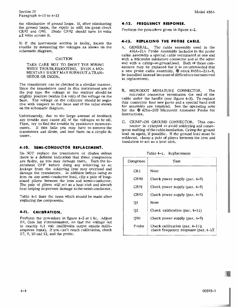
Table 4-1 lists the tests which should be made after replacing the components.
4-11. CALIBRATION.
Perform the procedure in figure 4-2 at 1 kc. Adjust R9, Gain Set Potentiometer, so that the voltage out is exactly 0.1 volt (millivolts output equals milli- amperes input). If you can’t reach calibration, check R7, 9, 10 and 12, and the probe.
4-12. FREQUENCY RESPONSE.
Perform the procedure given in figure 4-2.
4-13. REPLACING THE PROBE CABLE.
A. GENERAL. The cable assembly used i n the 456A-21A Probe Assembly includes in the probe
cable assembly a special cable terminated at one end with a Microdot miniature connector and at the other end with a crimp-on groundlead. Both of these con- nectors may be replaced but i t is recommended that a new probe cable assembly, stock #456A-21A-8, be installed instead because of difficulties encountered in replacement.
MIDRODOT MlNlATURE CONNECTOR. The micrcdot connector terminates the end of the
cable under the handle (see figure 4-3). To replace this connector four new parts and a special hand tool for assembly are required. See the operating note fo r the 425A-21B Microvolt Ammeter Probe for instructions.
C. CRIMP-ON GROUND CONNECTOR. This con- nector is crimped to avoid soldering and conse-
quent melting of the cableinsulation. Crimp the ground lead on again, if possible. If the ground lead must be soldered, clamp a pair of pliers between the iron and insulation to act a s a heat sink.
Component
CR1
CR90
CR91
CR92
Q1
Q2
Q90
Probe
Table 4-1. Replacement
Test
None
Check power supply (par. 4-9)
Check power supply (par. 4-9)
Check power supply (par. 4-9)
None
Check calibration (par. 4-11)
Check power supply (par. 4-9)
Check Calibration (par. 4-11); check frequency response (par. 4-12:
00395-1 4-4

Model 456A Section IV Figure 4-3
PROBE CABLE
INDIVIDUAL PARTS NOT FIELD REPLACEABLE
PROBE GROUND LEAD ASSEMBLY
SHOULD POINT AS SHOWN
F R O N T PANEL OF INSTRUMENT
Figure 4-3. Exploded View of Probe Assembly
00395-1 4-5
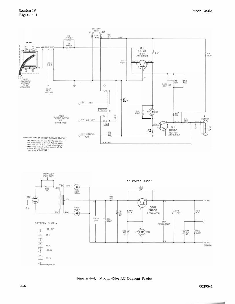
Section IV Figure 4-4
PROBE
Model 456A
C5 .01 UF
R 8 270
300
AC POWER SUPPLY
R93
Figure 4-4. Model 456A AC Current Probe
00395-1 4-6

Model 456A Section V Paragraphs 5-1 to 5-3
S E C T I O N V REPLACEABLE P A R T S
5-1. I N T R O D U C T I O N .
This section contains information for ordering re- placement parts for the 456A AC Current Probe.
5-2. TABLE O F REPLACEABLE PARTS.
Table 5-1 lists replaceable parts in alpha-numerical order of reference designators. At the end of the table a r e listed miscellaneous items such as knobs which have no assigned reference designators.
Detailed information on a part used more than once is listed opposite the f i rs t reference designator apply- ing to the part to appear in the table. Other reference designators applying to the same part reference the initial designator. The detailed information includes the following:
1) Full description of the part.
2) Manufacturer of the part in a five digit code -- see appendix codes, List of Manufacturers.
3) Total quantity used in the instrument (TQ column).
4) Recommended spare quantity for complete main- tenance during one year of isolated service (RS column).
5-3. O R D E R I N G I N F O R M A T I O N .
To order a replacement part, address order o r in- quiry either to your authorized @ sales office or to
CUSTOMER SERVlCE Hewlett-Packard Company 395 Page Mill Road Palo Alto, California
or, in Western Europe, to
Hewlett-Packard S. A. Rue du Vieux Billard No. 1 Geneva, Switzerland
Specify the following information on a part:
1) Model and serial number of the instrument. Be sure to include the three-digit serial prefix.
2) @ stock number.
3) Circuit reference designator,
4) Description.
To order a part not listed in table 5-1, give a complete description of the part including i ts function and lo- cation in the circuit.
Table 5-1. Replaceable Par t s (Sheet 1 of 4)
Ckt Ref.
BT1,2
BT 3
c1 c 2
c 3
c4, 5
C6
Description
Battery, mercury cell: 4V, TR 233R
Battery, mercury cell: 5. 33V, TR 234
Not assigned
Capacitor: fixed, electrolytic, 200 pf -10% +loo%, 3 vdcw
Capacitor: fixed, electrolytic, 500 pf -10% +loo%, 3 vdcw
Capacitor: fixed, ceramic, . O l pf 120%, 1000 vdcw
Capacitor: fixed, electrolytic, 10 pf -10% +loo%, 25 vdcw
M f r *
37942
37942
56289
56289
56289
56289
Stock No.
1420-0005
1420-0006
0180-0060
0180-0063
0150-0012
0180-0059
2
1
1
1
1
1
See introduction to this section
00395-1 5- 1

Section V Model 456A
Table 5-1. Replaceable Pa r t s (Sheet 2 of 4)
Ckt Ref.
c 7
C8 thru C89
c90, 91
c92
c93
c94
C R 1
CR2 thru CR89
CR90, 91
CR92
J1
J2
P1
P2 thru P89
P90
Q1,2
23 thru Q89
Q90
3 1 thru 34
R5
Description
Capacitor: fixed, ceramic, 5 p f 500 vdcw Optimum value selected at factory Average value shown
Not assigned
Capacitor: fixed, electrolytic, 40 uf -15% +loo%, 50 vdcw
Capacitor: fixed, electrolytic, 100 pf -10% +loo%, 15 vdcw
Same as C6
Capacitor: fixed, electrolytic, 100 pf, 12 vdcw
Diode, silicon: breakdown
Not assigned
Diode, germanium: 1N38A
Diode, silicon
Connector, female: red
Connector, female: black
Connector, male: output
Not assigned
Cable, power
Transistor: 2N1516 / OC170 Not assigned
Transistor: 2N650
Resistor: fixed, 24 ohms +5%,
composition, . l w
Resistor: fixed, composition, 22 ohms Part of Probe Ground Lead Assembly Component not separately replaceable
Mfr *
96095
56289
56289
56289
28480
08792
28480
00373
00373
24655
70903
73445
04713
01121
S t o c k No
0150-0008
0180-0050
0180-0061
0180-0039
G-29A-17
1910-0002
G-31A-15L
1251-0131
1251-0132
1250-0092
8120-0037
1850-0003
1850-0048
0674-0002
RS
1
1
1
1
1
2
1
1
1
1
1
2
1
1
*See introduction to this section 5 -2
00395-1

. -
Model 456A
Table 5-1. Replaceable Parts (Sheet 3 of 4)
Section V
Ckt Ref.
R6
R7
R8
R9
R10
R11
R12
R13
R14
R15 thru R89
R90
R91
R92
R93
R94
R95
s1 T1 thru T89
T90
Description
Resistor: fixed, composition, 2.7 ohms *lo%, 1/2 w
Resistor: fixed, composition, 3300 ohms +lo%, 1/2 W
Resistor: fixed, composition, 2700 ohms *lo%, 1/2 W
Resistor: variable, composition, linea taper, 100 ohms +30%, 1/3 W
Resistor: fixed, composition, 100 ohms +lo%, 1/2 W
Same as R6
Resistor: fixed, deposited carbon, 392 ohms +1%, 1/2 W
Resistor: fixed, composition, 180 ohms *lo%, 1/2 w Optimum value selected at factory Average value shown
Resistor: fixed, composition, 2400 ohms +5%, 1/2 W
Not assigned
Resistor: fixed, composition, 15,000 ohms *lo%, 2 W
Resistor: fixed, composition, 680 ohms +lo%, 1/2 W
Resistor: fixed, composition, 10,000 ohms *lo%, 1/2 W
Resistor: fixed, composition, 6800 ohms *lo%, 1/2 W
Resistor: fixed, deposited carbon, 4000 ohms *l%, 1/2 W
Resistor: fixed, deposited carbon, 2250 ohms *l%, 1/2 W
Switch, slide: DPDT
Not assigned
Transformer, power
Mfr *
01121
01121
01121
11450
01121
19101
01121
01121
01121
01121
01121
01121
19101
19101
42190
28480
Stock No.
0699-0001
0681-3321
0681-2121
2 100-0108
0681-1011
0721-0301
0681-1811
0686-2425
0693-1531
0681-6811
0687-1031
0681-6821
0121-0132
0721-0120
3101-0011
9100-0120
'Qd
2
1
1
1
1
1
1
1
1
1
1
1
1
1
1
1
RS'
1
1
1
1
1
1
1
1
1
1
1
1
1
1
1
1
*See introduction to this section
00395-1 5-3
Section V Model 456A
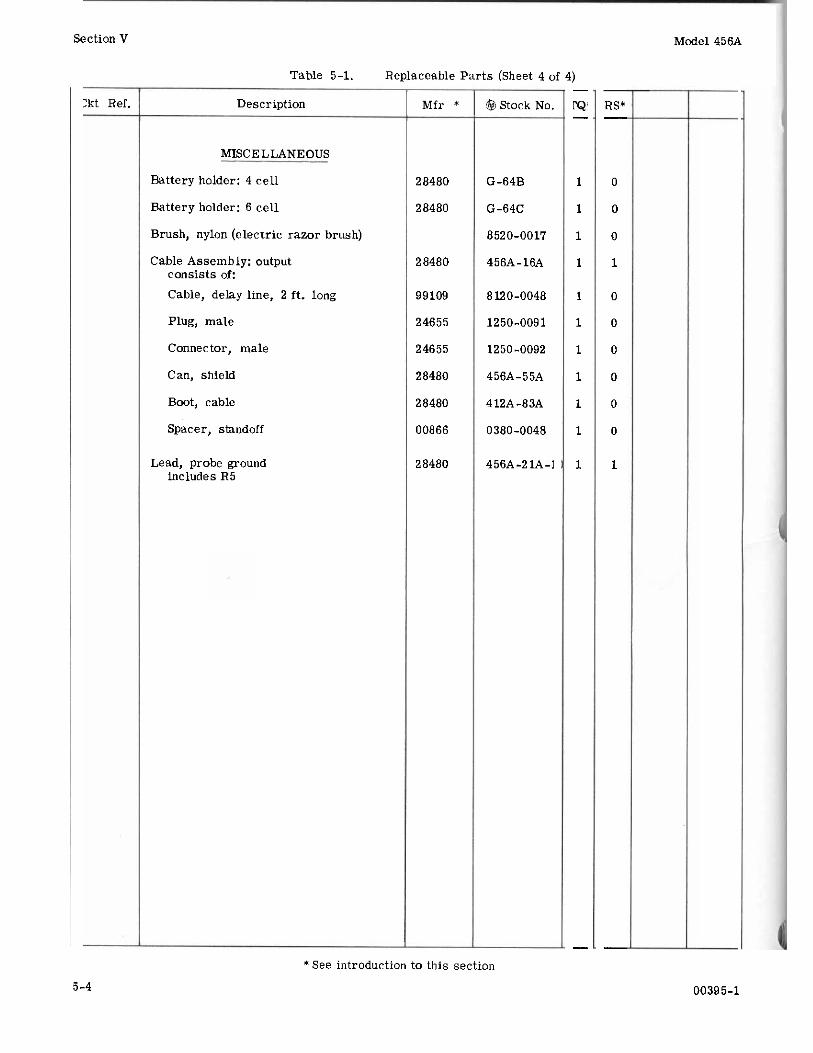
Table 5-1. Replaceable Parts (Sheet 4 of 4)
Ckt Ref. Description
MISCELLANEOUS
Battery holder: 4 cell
Battery holder: 6 cell
Brush, nylon (electric razor brush)
Cable Assembly: output consists of: Cable, delay line, 2 ft. long
Plug, male
Connector, male
Can, shield
Boot, cable
Spacer, standoff
Lead, probe ground includes R5
Mfr *
28480
28480
28480
99109
24655
24655
28480
28480
00866
28480
Stock No.
G-64B
G-64C
8520-0017
456A-16A
8120-0048
1250-0091
1250-0092
4 56A- 5 5A
412A-83A
0380-0048
4 56A -2 lA
1
1
1
1
1
1
1
1
1
1
1
RS'
0
0
0
1
0
0
0
0
0
0
1
*See introduction to this section
5-4 00395-1