how to use these analysis - reu houston 2017 | reserves...
TRANSCRIPT
Copyright © Intelligent Solutions, Inc. 2014
How to Use These Analysis
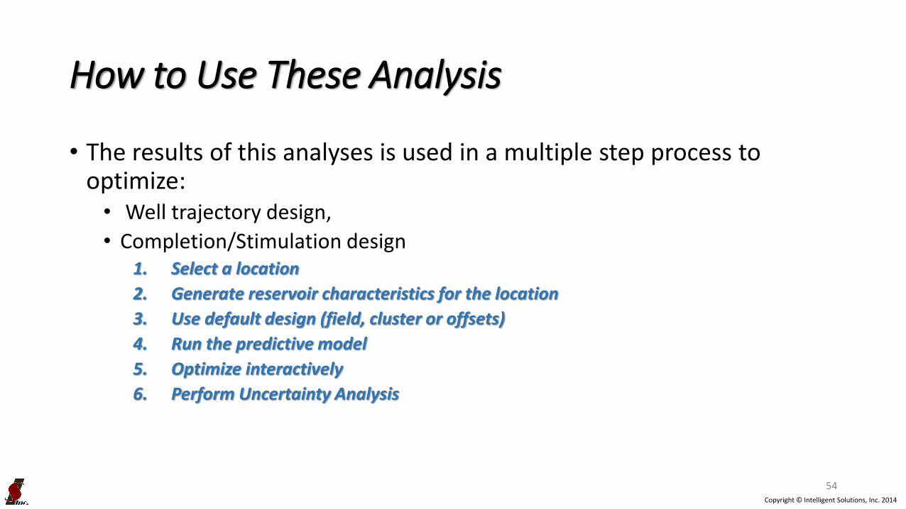
• The results of this analyses is used in a multiple step process to optimize:• Well trajectory design,
• Completion/Stimulation design 1. Select a location
2. Generate reservoir characteristics for the location
3. Use default design (field, cluster or offsets)
4. Run the predictive model
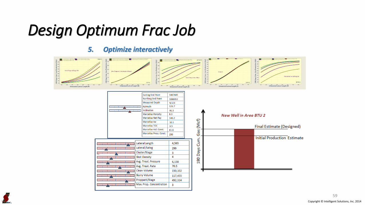
5. Optimize interactively
6. Perform Uncertainty Analysis
54

Copyright © Intelligent Solutions, Inc. 2014
Design Optimum Frac Job
55
1. Select a location
2. Generate reservoir characteristics for the location
3. Use default design (field, cluster or offsets)
NOTE: All data presented here have been modified to protect confidentiality.

Copyright © Intelligent Solutions, Inc. 2014
Design Optimum Frac Job
56
1. Select a location
2. Generate reservoir characteristics for the location
3. Use default design (field, cluster or offsets)
Porosity
NOTE: All data presented here have been modified to protect confidentiality.

Copyright © Intelligent Solutions, Inc. 2014
Design Optimum Frac Job
57
1. Select a location
2. Generate reservoir characteristics for the location
3. Use default design (field, cluster or offsets)
PorositySwi
NOTE: All data presented here have been modified to protect confidentiality.

Copyright © Intelligent Solutions, Inc. 2014
Design Optimum Frac Job
58
1. Select a location
2. Generate reservoir characteristics for the location
3. Use default design (field, cluster or offsets)
PorositySwi
NOTE: All data presented here have been modified to protect confidentiality.
Copyright © Intelligent Solutions, Inc. 2014
Design Optimum Frac Job
59
5. Optimize interactively

Copyright © Intelligent Solutions, Inc. 2014
Design Optimum Frac Job
60
6. Perform Uncertainty Analysis
NOTE: All data presented here have been modified to protect confidentiality.

Copyright © Intelligent Solutions, Inc. 2014
Design Optimum Frac Job
61

Copyright © Intelligent Solutions, Inc. 2014
Thank You for your Attention !
Questions?

Copyright © Intelligent Solutions, Inc. 2014
Shale Formation EvaluationData-Driven Synthetic Geo-mechanical Logs
Marcellus Shale
Copyright © Intelligent Solutions, Inc. 2014
• Introduction
• Artificial intelligence & Data Mining
• Methodology & Workflow
• Results & Discussions
• Conclusions
OUTLINE
Copyright © Intelligent Solutions, Inc. 2014
• Rock Geomechanical properties defines Principal Stress Profiles of a reservoir.
• Principal Stress Profiles are the key to understanding Fracture Characteristics.
• Having access to Geomechanical data can assist engineers and geoscientists during modeling and hydraulic fracture treatment design.
Geo-Mechanical Well Logs

Copyright © Intelligent Solutions, Inc. 2014
• Geomechanical Properties from logs:
– Shear, Young and Bulk Modulus (Mpsi)
– Total Minimum Horizontal Stress (psi/ft)
– Poisson’s Ratio
Geo-Mechanical Well Logs

Copyright © Intelligent Solutions, Inc. 2014
Geo-Mechanical Well Logs

Copyright © Intelligent Solutions, Inc. 2014
• Running Geomechanical well logs (in all wells in a Shale asset) is not common practice.
• This may be attributed to the cost associated with running such logs.
• Building a model of Geomechanical properties distribution (Map and Volume) for a shale can have many advantage:
– Assist in understanding the rock mechanical behavior,
– Assist in designing effective hydraulic fractures.
Geo-Mechanical Well Logs
Copyright © Intelligent Solutions, Inc. 2014
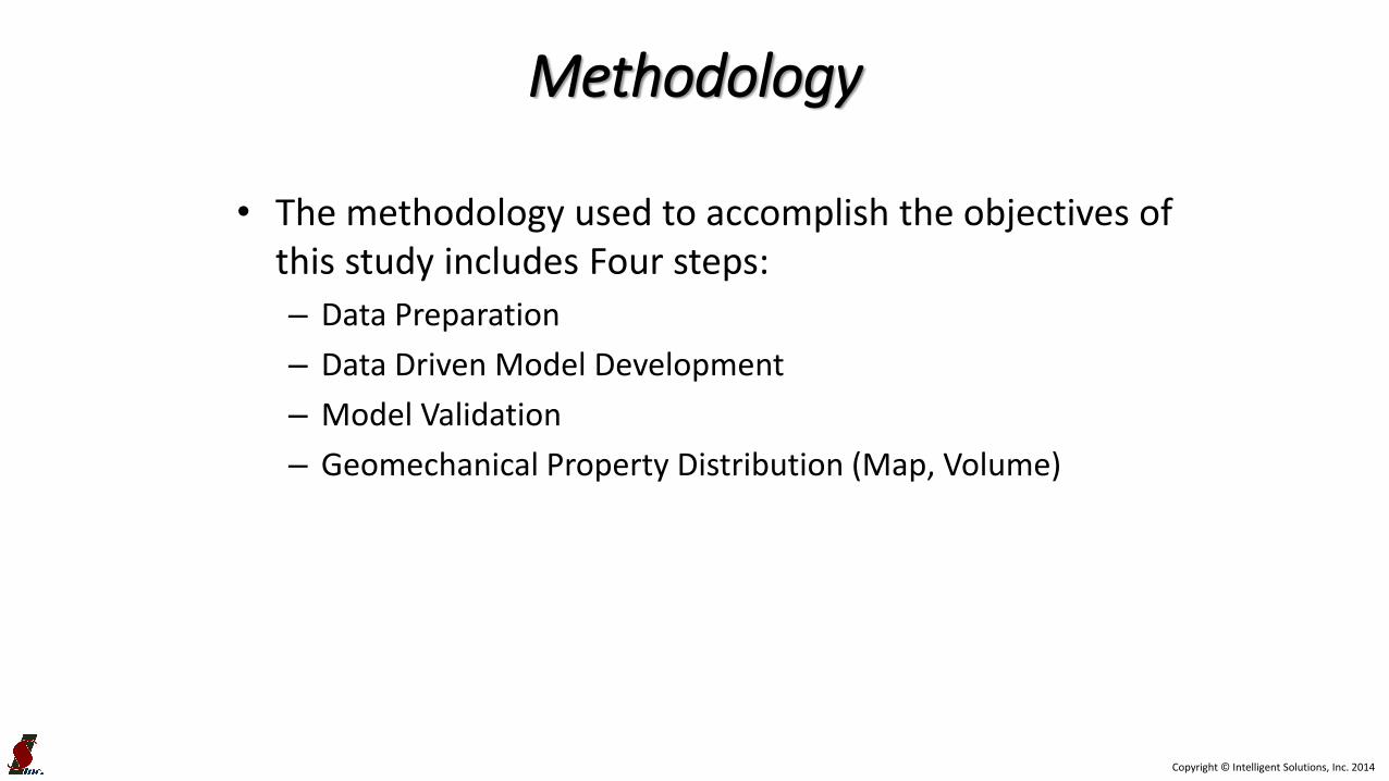
• The methodology used to accomplish the objectives of this study includes Four steps:
– Data Preparation
– Data Driven Model Development
– Model Validation
– Geomechanical Property Distribution (Map, Volume)
Methodology
Copyright © Intelligent Solutions, Inc. 2014
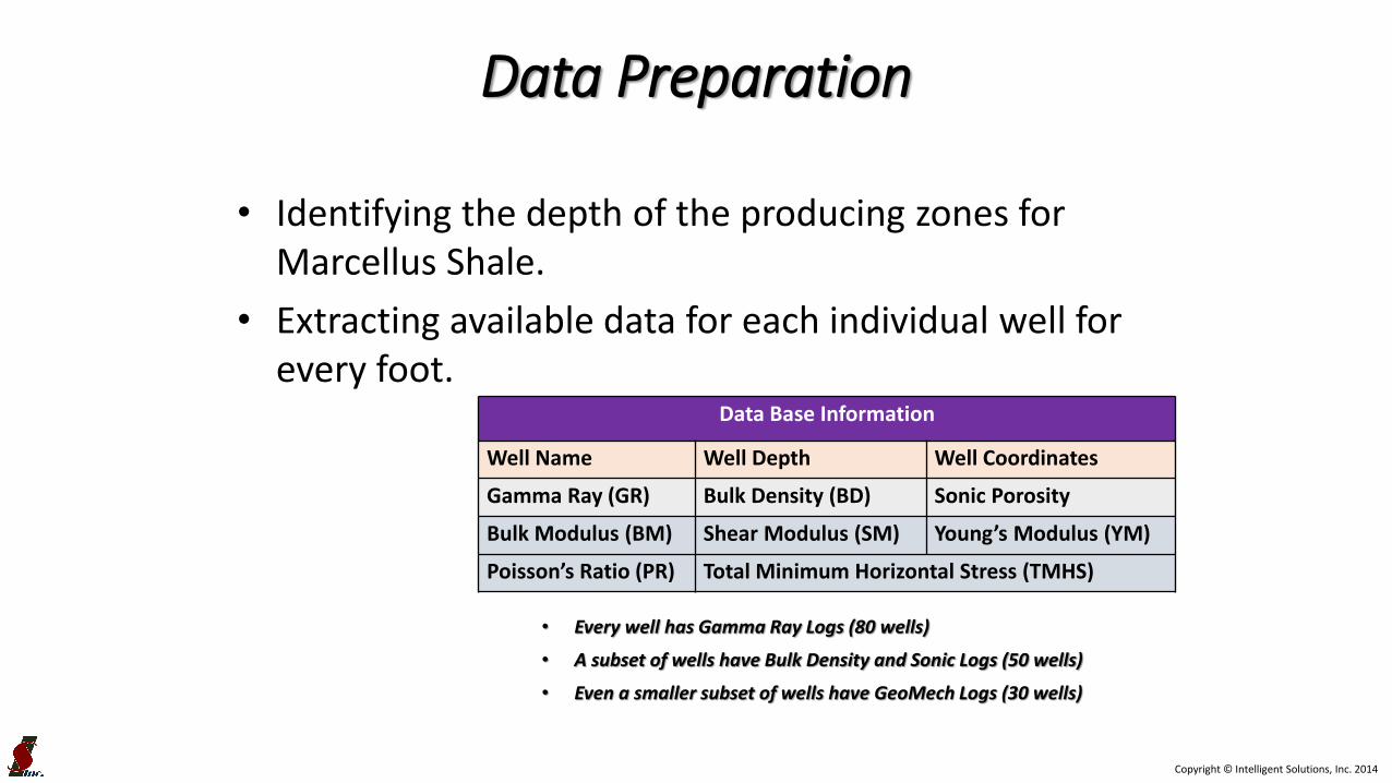
• Identifying the depth of the producing zones for Marcellus Shale.
• Extracting available data for each individual well for every foot.
Data Preparation
Data Base Information
Well Name Well Depth Well Coordinates
Gamma Ray (GR) Bulk Density (BD) Sonic Porosity
Bulk Modulus (BM) Shear Modulus (SM) Young’s Modulus (YM)
Poisson’s Ratio (PR) Total Minimum Horizontal Stress (TMHS)
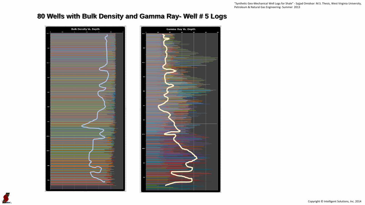
• Every well has Gamma Ray Logs (80 wells)
• A subset of wells have Bulk Density and Sonic Logs (50 wells)
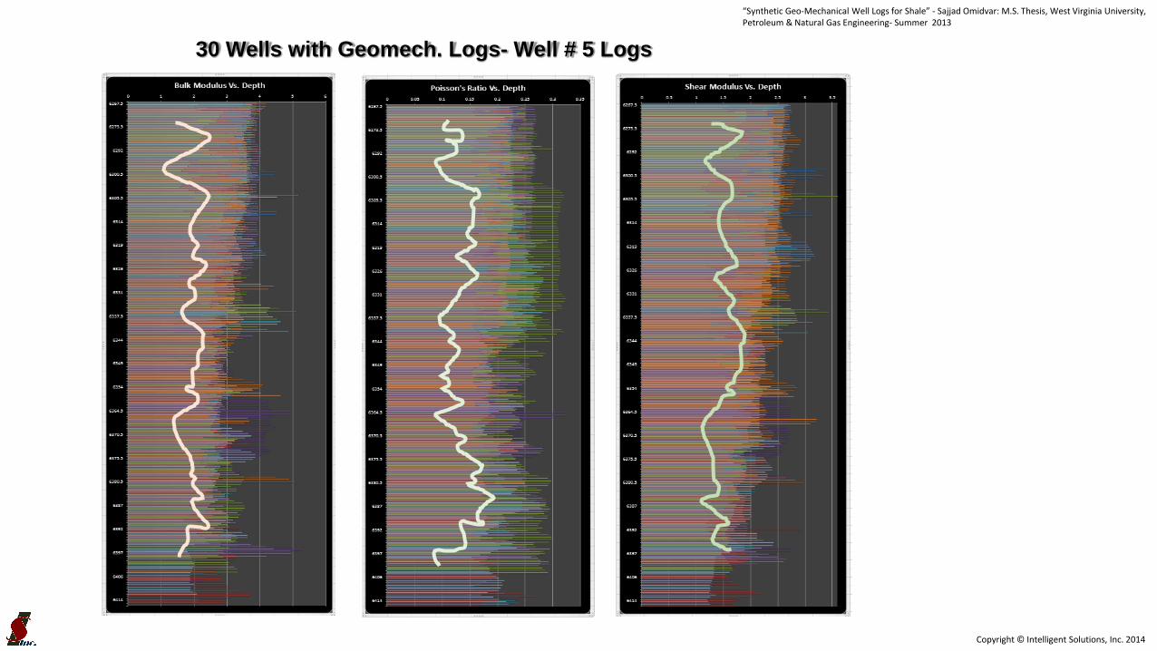
• Even a smaller subset of wells have GeoMech Logs (30 wells)

Copyright © Intelligent Solutions, Inc. 2014
Data Preparation“Synthetic Geo-Mechanical Well Logs for Shale” - Sajjad Omidvar: M.S. Thesis, West Virginia University, Petroleum & Natural Gas Engineering- Summer 2013

Copyright © Intelligent Solutions, Inc. 2014
• The prepared database was processed using Neural Network:
– Conventional Models
– Generating synthetic Bulk Density and Sonic for the 30 wells with missing Sonic logs.
– Geo-Mechanical Models
– Generating synthetic Geomechanical logs for 50 wells with missing Geomech logs.
Data-Driven Model Development“Synthetic Geo-Mechanical Well Logs for Shale” - Sajjad Omidvar: M.S. Thesis, West Virginia University, Petroleum & Natural Gas Engineering- Summer 2013
Copyright © Intelligent Solutions, Inc. 2014
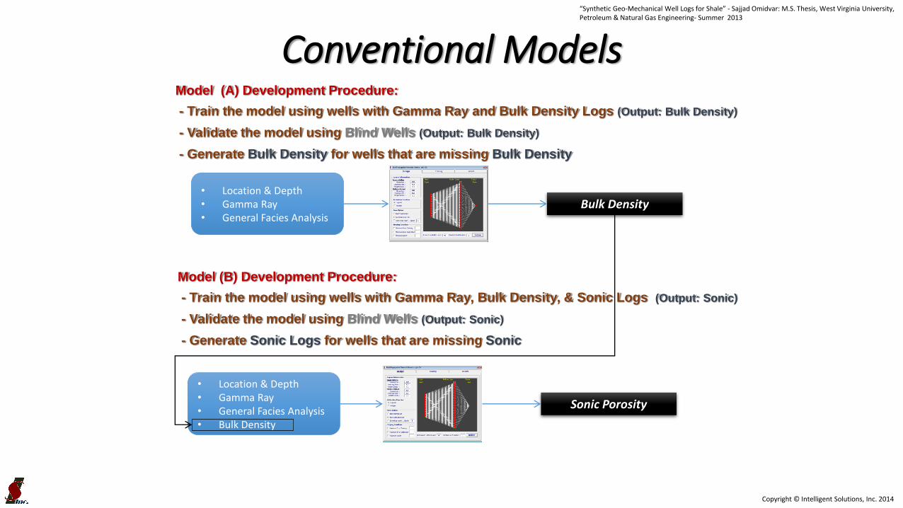
Conventional ModelsModel (A) Development Procedure:
- Train the model using wells with Gamma Ray and Bulk Density Logs (Output: Bulk Density)
- Validate the model using Blind Wells (Output: Bulk Density)
- Generate Bulk Density for wells that are missing Bulk Density
• Location & Depth• Gamma Ray• General Facies Analysis
• Location & Depth• Gamma Ray• General Facies Analysis• Bulk Density
Bulk Density
Sonic Porosity
Model (B) Development Procedure:
- Train the model using wells with Gamma Ray, Bulk Density, & Sonic Logs (Output: Sonic)
- Validate the model using Blind Wells (Output: Sonic)
- Generate Sonic Logs for wells that are missing Sonic
“Synthetic Geo-Mechanical Well Logs for Shale” - Sajjad Omidvar: M.S. Thesis, West Virginia University, Petroleum & Natural Gas Engineering- Summer 2013

Copyright © Intelligent Solutions, Inc. 2014
Training & Blind Wells“Synthetic Geo-Mechanical Well Logs for Shale” - Sajjad Omidvar: M.S. Thesis, West Virginia University, Petroleum & Natural Gas Engineering- Summer 2013

Copyright © Intelligent Solutions, Inc. 2014
Results (Blind Well #1)“Synthetic Geo-Mechanical Well Logs for Shale” - Sajjad Omidvar: M.S. Thesis, West Virginia University, Petroleum & Natural Gas Engineering- Summer 2013

Copyright © Intelligent Solutions, Inc. 2014
Results (Blind Well #2)“Synthetic Geo-Mechanical Well Logs for Shale” - Sajjad Omidvar: M.S. Thesis, West Virginia University, Petroleum & Natural Gas Engineering- Summer 2013

Copyright © Intelligent Solutions, Inc. 2014
Results (Blind Well #3)“Synthetic Geo-Mechanical Well Logs for Shale” - Sajjad Omidvar: M.S. Thesis, West Virginia University, Petroleum & Natural Gas Engineering- Summer 2013
Copyright © Intelligent Solutions, Inc. 2014
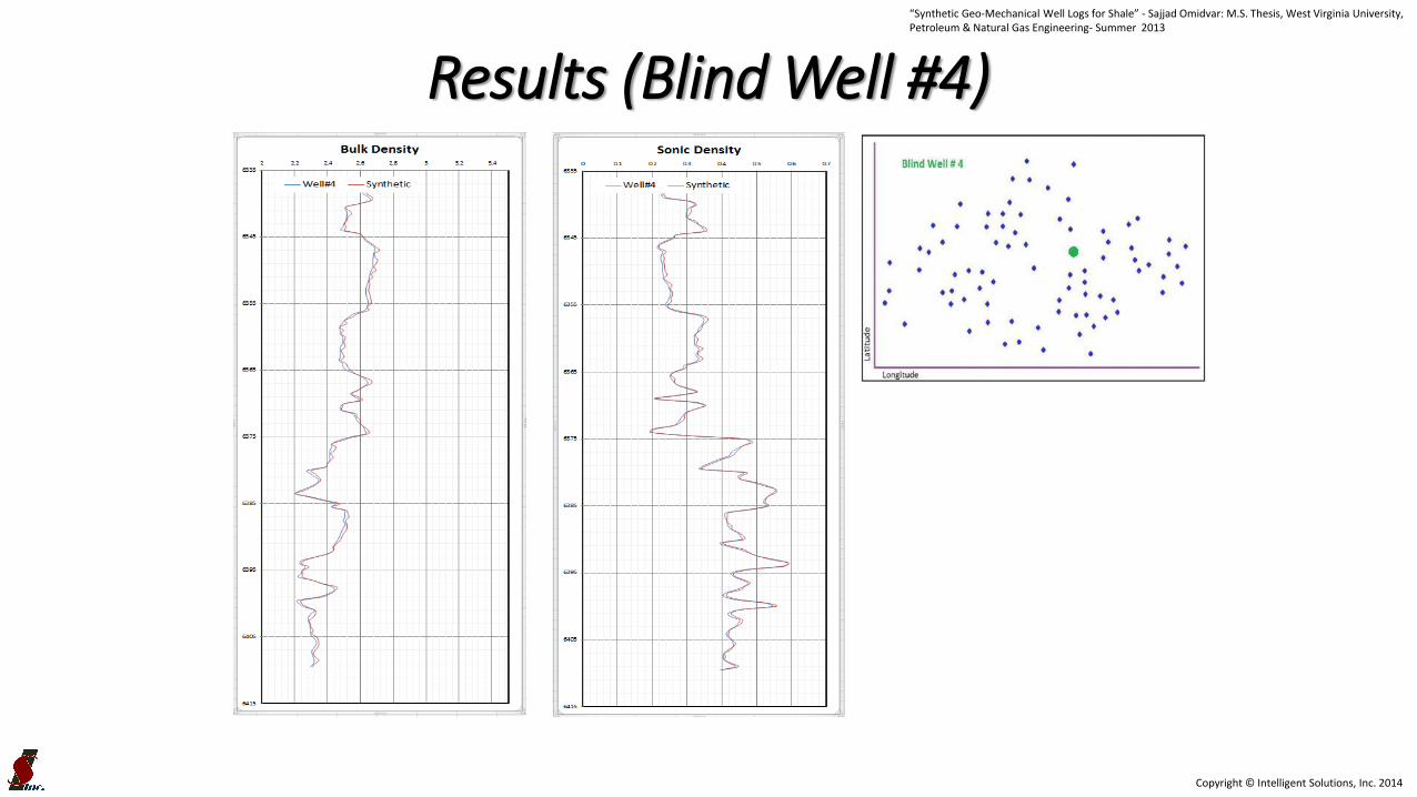
Results (Blind Well #4)“Synthetic Geo-Mechanical Well Logs for Shale” - Sajjad Omidvar: M.S. Thesis, West Virginia University, Petroleum & Natural Gas Engineering- Summer 2013

Copyright © Intelligent Solutions, Inc. 2014
GeoMechanical Models
Model Development Procedure:
- Train the model using wells with Gamma Ray and Bulk Density & Sonic Logs
(Output: All Geomechnical Logs)
- Validate the model using Blind Wells (Output All Geomechnical Logs)
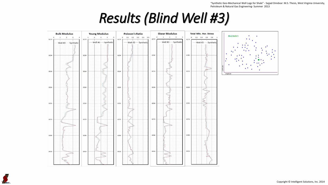
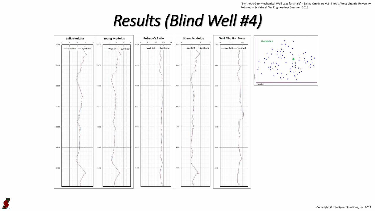
- Generate Bulk, Shear, and Young’s Modulus as well as Poisson’s Ratio and Minimum
Horizontal Stress, for wells that are missing Geomechnical Properties.
• Location & Depth• General Facies
Analysis• Gamma Ray• Bulk Density• Sonic
Geomechanical Logs:- Bulk Modulus- Shear Modulus- Young’s Modulus- Poisson’s Ratio- Min. Horiz. Stress
“Synthetic Geo-Mechanical Well Logs for Shale” - Sajjad Omidvar: M.S. Thesis, West Virginia University, Petroleum & Natural Gas Engineering- Summer 2013

Copyright © Intelligent Solutions, Inc. 2014
Training & Blind Wells“Synthetic Geo-Mechanical Well Logs for Shale” - Sajjad Omidvar: M.S. Thesis, West Virginia University, Petroleum & Natural Gas Engineering- Summer 2013

Copyright © Intelligent Solutions, Inc. 2014
Results (Blind Well #1)“Synthetic Geo-Mechanical Well Logs for Shale” - Sajjad Omidvar: M.S. Thesis, West Virginia University, Petroleum & Natural Gas Engineering- Summer 2013

Copyright © Intelligent Solutions, Inc. 2014
Results (Blind Well #2)“Synthetic Geo-Mechanical Well Logs for Shale” - Sajjad Omidvar: M.S. Thesis, West Virginia University, Petroleum & Natural Gas Engineering- Summer 2013
Copyright © Intelligent Solutions, Inc. 2014
Results (Blind Well #3)“Synthetic Geo-Mechanical Well Logs for Shale” - Sajjad Omidvar: M.S. Thesis, West Virginia University, Petroleum & Natural Gas Engineering- Summer 2013
Copyright © Intelligent Solutions, Inc. 2014
Results (Blind Well #4)“Synthetic Geo-Mechanical Well Logs for Shale” - Sajjad Omidvar: M.S. Thesis, West Virginia University, Petroleum & Natural Gas Engineering- Summer 2013

Copyright © Intelligent Solutions, Inc. 2014
Results (Blind Well #5)
?
“Synthetic Geo-Mechanical Well Logs for Shale” - Sajjad Omidvar: M.S. Thesis, West Virginia University, Petroleum & Natural Gas Engineering- Summer 2013
Copyright © Intelligent Solutions, Inc. 2014
80 Wells with Bulk Density and Gamma Ray- Well # 5 Logs
“Synthetic Geo-Mechanical Well Logs for Shale” - Sajjad Omidvar: M.S. Thesis, West Virginia University, Petroleum & Natural Gas Engineering- Summer 2013
Copyright © Intelligent Solutions, Inc. 2014
30 Wells with Geomech. Logs- Well # 5 Logs
“Synthetic Geo-Mechanical Well Logs for Shale” - Sajjad Omidvar: M.S. Thesis, West Virginia University, Petroleum & Natural Gas Engineering- Summer 2013

Copyright © Intelligent Solutions, Inc. 2014
88
30 Wells with Geomech. Logs- Well # 5 Logs
“Synthetic Geo-Mechanical Well Logs for Shale” - Sajjad Omidvar: M.S. Thesis, West Virginia University, Petroleum & Natural Gas Engineering- Summer 2013
Copyright © Intelligent Solutions, Inc. 2014
89
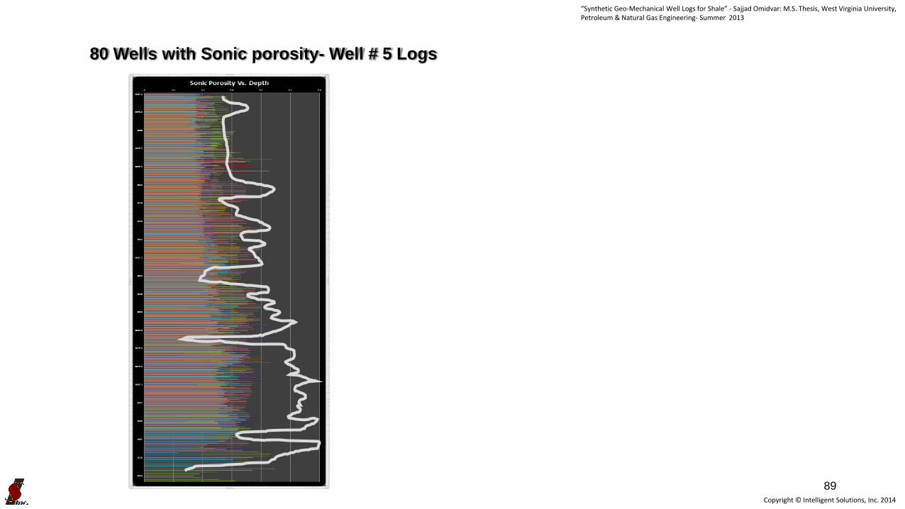
80 Wells with Sonic porosity- Well # 5 Logs
“Synthetic Geo-Mechanical Well Logs for Shale” - Sajjad Omidvar: M.S. Thesis, West Virginia University, Petroleum & Natural Gas Engineering- Summer 2013

Copyright © Intelligent Solutions, Inc. 2014
• Generate Sonic Log for the Blind Well #5 using the Synthetic Well Log Generation Model (Model B).
• Use the new (synthetic) Sonic Log and generate Geomechnical Log, and compare it with the actual Geomechnical Logs.
Blind Well #5
• Location & Depth• Gamma Ray• General Facies Analysis• Bulk Density
Sonic Porosity

Copyright © Intelligent Solutions, Inc. 2014
Slide 91
Synthetic Sonic for Blind Well #5

Copyright © Intelligent Solutions, Inc. 2014
Results (Blind Well #5)
Copyright © Intelligent Solutions, Inc. 2014
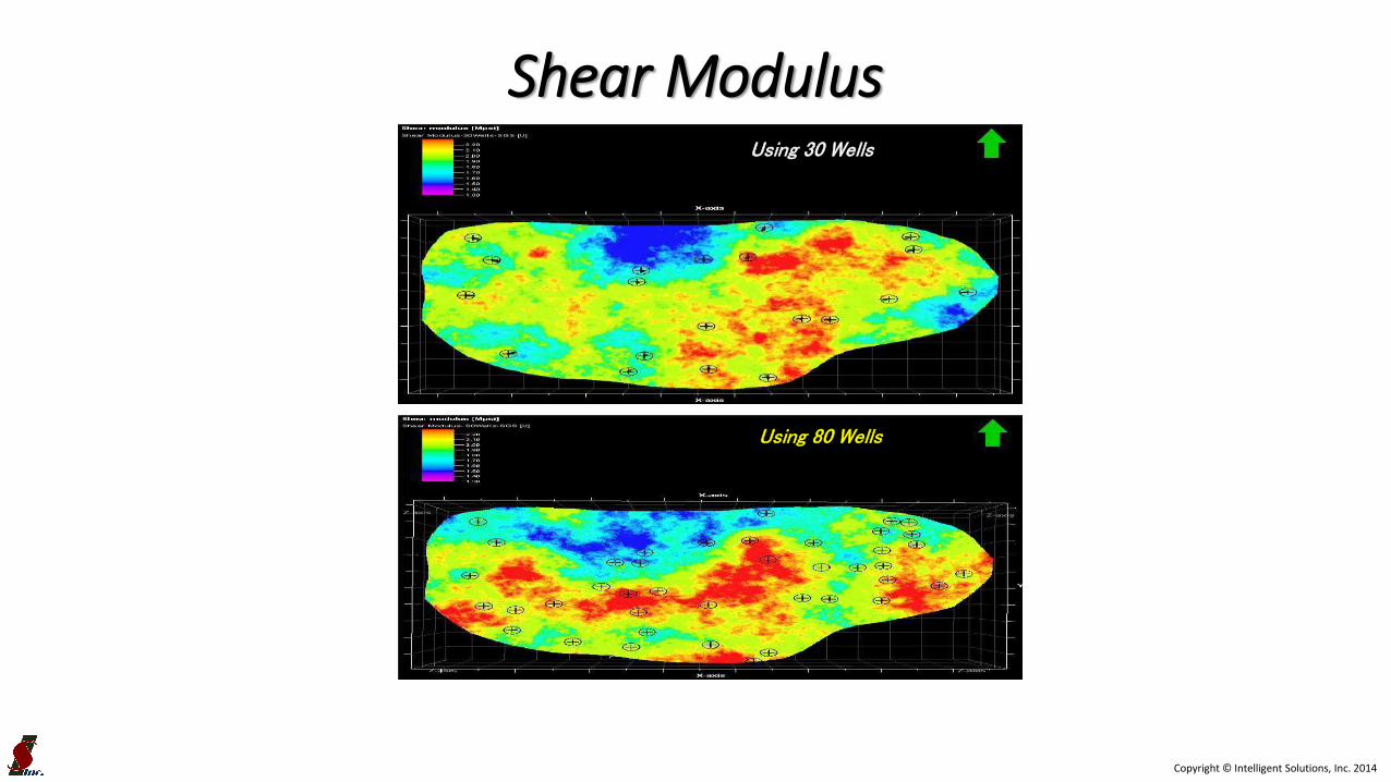
• Comparing distribution of geomechanical properties throughout the asset:
– Using the geomechanical logs from 80 wells versus 30 wells.
– Sequential Gaussian Simulation (SGS)
Geo-Mechanical Property Distribution

Copyright © Intelligent Solutions, Inc. 2014
Bulk ModulusUsing 30 Wells
Using 80 Wells
Copyright © Intelligent Solutions, Inc. 2014
Shear ModulusUsing 30 Wells
Using 80 Wells

Copyright © Intelligent Solutions, Inc. 2014
Young ModulusUsing 30 Wells
Using 80 Wells

Copyright © Intelligent Solutions, Inc. 2014
Poisson’s RatioUsing 30 Wells
Using 80 Wells

Copyright © Intelligent Solutions, Inc. 2014
Total Minimum Horizontal StressUsing 30 Wells
Using 80 Wells

Copyright © Intelligent Solutions, Inc. 2014
• Artificial Intelligence & Data Mining can be used effectively to generate synthetic Geo-Mechanical well logs.
• Artificial Intelligence & Data Mining can be used as a tool to quality check the existing well logs.
• Combining synthetic and actual Geo-Mechanical well logs in a shale asset, can generate Geo-Mechanical properties distribution models with good resolution and accuracy.
• Having Geo-Mechanical properties distribution models can assist completion engineers to design more effective hydraulic fractures.
Conclusions