how to make a frame panel
TRANSCRIPT

How to make a
FRAME& PANELCabinet Door
A guide to using profile scribing and raised panel cutters
BOOK/PDS 2011 21/3/11 14:24 Page 1

Profile scribing and raisedmoulding cutters can be used to
produce traditional panelled framedoors to a professional standard.
This booklet is intended for both amateur andprofessional woodworkers and aims to outlinethe techniques involved and the basicequipment required. With 1/4” shank profilescribing and raised panel moulding cutters,low powered routers (above 750 watts) can
be used for this purpose. This allowsanyone with basic woodworking
skills, tools and equipmentto produce high quality,decorative and attractivecabinets and fitted
furniture.
BOOK/PDS 2011 21/3/11 14:25 Page 2

8
1
2
CONTENTS
3
5
6
7
4
FRAME & PANEL DOOR CONSTRUCTION ___________2-9Door Styles _____________________________4 - 5Component Dimensions ___________________6 - 7Meeting Stiles ___________________________8 - 9
PROFILE SCRIBING CUTTERS__________________10-17Profile Scribing Cutter Assembly __________12 - 13Profile Scribing Cutter Sets ______________14 - 15Profile Scriber Multi Set _____________________16Panel Door Sets ___________________________17
MATERIALS &OTHER EQUIPMENT _______18-21Other Equipment_______________________20 - 21
THE FRAME_____________22-33The Scribe ______________________________23 - 27The Edge Profile _________________________28 - 30Shaped Rails ____________________________31 - 33
THE PANELS _____________34-41Panel Styles ______________________________35Jointing______________________________36 - 37Assembly ____________________________38 - 39Calculating the Panel Size________________40 - 41
PANEL CUTTERS _________42-49Vertical __________________________________43Bearing Guided and Horizontal ____________44 - 45Radiused and Ogee_____________________46 - 47Ovolo, Classic and Bevel ________________48 - 49
USING RAISED PANEL CUTTERS _________50-57Setting Up _______________________________51Making a Template _____________________52 - 53Combined Jig and Scoring _______________54 - 55Lead-On Piece ____________________________56Summary of Safety Techniques _______________57
DOOR ASSEMBLY ________58-62Hinges_______________________________60 - 61Edge Moulding ____________________________62
© 2011 Trend Machinery & Cutting Tools Ltd. All rights reserved. No part of this publication may be reproduced or transmitted without prior permission.Trend reserves the right to revise product specifications at any time without notice. Colours may vary. E&OE. ® All Trademarks Acknowledged.
BOOK/PDS 2011 21/3/11 14:25 Page 3

2
Moulded EdgesThe inside edges of the stiles and railsare grooved and moulded, the groovebeing both deep enough to accept theedge of an infill panel and the stub tenonto form the frame joints.FRAME &
PANEL DOORCONSTRUCTION
Panelled door frames are made up oftwo vertical stiles and two horizontal
rails. The inside edge of the stiles andrails are grooved to take the panel edgeand the rail end tenon. Scribed Joint
The end of the rails are cut to formthe joint tenon and scribed to matchthe decorative rail/stile edgemoulding.
1
BOOK/PDS 2011 21/3/11 14:25 Page 4

3
Infill PanelsThe panels can be made from solid timber, veneered plywood orcomposite board. They can be cut as flat panels or with atraditional raised central area (raised and fielded panels). Themould on the panel can vary from a plain bevel to a moreelaborate decorative profile.
Top and Bottom RailsAlthough for simplicity the frame rails and stiles can be ofthe same width, a more proportionally balancedappearance can be achieved by increasing the width ofthe bottom rail. Alternatively, shaping the inside edge ofthe top and/or bottom rail produces a more decorativeappearance. The actual width of the stiles and rails is amatter of visual proportion, but must be wide enough toprovide adequate strength in relation to the door size.
MuntinThe sub-division of a door by the introduction ofhorizontal and vertical rails is generally dictated byits overall size, although additional strength isbeneficial when constructing large doors. Widedoors normally have at least one central verticalmember (muntin) to improve their appearance,provide additional strength and reduce the panelsto more manageable sizes.
StilesThese must be strong enough to take thehinges, catch and handle.
BOOK/PDS 2011 21/3/11 14:25 Page 5

4
Rectangular Flat PanelledSimple rectangular frames can be fittedwith flat plywood or MDF panels,veneered to match the frame.Alternatively the frame and panel can befinished with a coloured stain or paint.
DOOR STYLES
Raised and Fielded Panelwith MuntinFor a more traditional style cabinet door,a raised and fielded panel can be fitted.These can be made using our range ofpanel raising cutters (see page 238).
Flat Ply Panel with MuntinRectangular frames can be furtherdivided into smaller panels by addingvertical (muntin) and horizontal rails.This is particularly advantageous whenmaking large doors that require morerigid construction.
BOOK/PDS 2011 21/3/11 14:25 Page 6

5
Flat Four PanelMulti-panelled doors can be produced,using the profile scribing cutter to cutthe scribed rail end and the profile edgemoulding on both edges of the middlerail and the two muntins.
Curved Top RailBy using trammels or radius jigs, theinside edges of the top and bottom railsof the door can be cut as a regular curve.The same jig or a template can then beused to shape the matching panel.
Cambrio Top RailCathedral top or cambrio shapes can beproduced using a pre-cut template forboth the rails and the matching paneledges. Shaped panel edges can beeasily cut using ball bearing guidedpanel raising cutters.
BOOK/PDS 2011 21/3/11 14:25 Page 7

m1m2
6
Frame ThicknessThe thickness of the rails and stiles should be
in relation to the overall door size and will
therefore effect the choice of cutter. Frames
for larger or heavier doors should be between
20-22mm, for smaller cabinet doors and fixed
panels 18-20mm thickness. This can be
further reduced to 16mm by using the smaller
profile/scribing cutters. A maximum frame
thickness of 26mm is possible using two of
the larger profile/scribing cutters sets (Trend
ref. PSC/20 and PSC/40 see page 237).
Rail and Stile WidthSuggested minimum width of rails and stiles
is 40mm dependant on their specific use or to
suit the design aesthetics. The maximum
width being about 60mm to 70mm.
COMPONENT DIMENSIONS
9.5mm 12mm
PSC/1 PSC/2PSC/10 PSC/20PSC/3 PSC/4PSC/30 PSC/40PSC/5PSC/50C149
Rail
Stile width (A) Stile width (A)
TT
Overall width (B)
Tenon Lengths (T)Rail LengthThe length of the rail components must take into account
the length of the stub tenon at each end. The length of
the tenons can be either 9.5mm or 12mm (see chart to
the right). The actual rail length is therefore:
The overall width of the frameless twice the stile widthplus twice the tenon length
orRail length = B - (2 x A) + (2 x T)
For information onPanel Dimensionssee page 237.
BOOK/PDS 2011 21/3/11 14:25 Page 8

7
min.=16mmmax.=18mm
min.=18mmmax.=22mm
11mm
4mm
22mm
41mm
3.5mm
6.3mm
PSC/3 Profiling
PSC/30 Profiling
min.=21mmmax.=26.5mm
min.=18mmmax.=22mm
15mm
6.3mm
22mm
46mm
4.7mm
4mm
PSC/4 Profiling
PSC/40 Profiling
min.=16mmmax.=18mm
PSC/10Profiling
11mm
4mm
41mm
4mm
PSC/1 Profiling
6.3mm
min.=18mmmax.=22mm
15mm
6.3mm
22mm
46mm
5.9mmmin.=18mmmax.=22mm
min.=21mmmax.=26.5mm4mm
PSC/20 Profiling
PSC/2 Profiling
min.=18mmmax.=22mm
10° min.=16mmmax.=18mm
11mm
4mm
22mm
41mm
6.3mm
PSC/5 Profiling
PSC/50 Profiling
Profile ScriberDimensions
BOOK/PDS 2011 21/3/11 14:25 Page 9

8
MEETING
STILES
10mmPanel
Equal (eg. 45mm)Equal (eg. 45mm) Equal (eg. 45mm)
Framethickness
Equal
As the width across each face of the two
meeting stiles would appear uneven, it is
common practice to cut a false narrow
line on the face of the stile. This should
be equal to the gap between the meeting
edges in order to visually balance them.
On cabinets with no centre partition or
vertical frame to form a stop behind the
meeting stiles of double doors, the
meeting edges are generally rebated.
Centre line of doors
45mm + rebate (eg. 55mm)45mm + rebate (eg. 55mm)
BOOK/PDS 2011 21/3/11 14:25 Page 10

1 To allow for the rebate, both meeting
stiles must be cut wider by the width
of the rebate (6 to 10mm). The
opposite faces of the two stiles are
rebated using a straight cutter
guided by the side fence, or a
bearing guided rebate cutter.
2 Cut a bead moulding along the
vertical edge of the front door with a
corner bead cutter using a diameter
equal to the width of the rebate.
Cutter Ref. 46/39 x 1/4TC
Cutter Ref. 9/71x1/4TC
Other sizes of cornerbeads are available
9
BOOK/PDS 2011 21/3/11 14:25 Page 11

10
2
ShimsEach set is supplied with a set ofshims to enable fine adjustmentsto be made to the tightness of thejoint. This ensures that not onlyaccurate joints can be produced,but also that the cutter set willcontinue to do so throughout itslife, even with regular honing.Mounted on an arbor, the
components of the profile scribing cutter sets are arrangedto cut the reverse scribe on therail ends, before beingrearranged to cut the matchingprofile and panel groove alongthe inside edges.
PROFILESCRIBINGCUTTERS
ArborThe cutter set is mounted ona precision arbor with either6.3mm, 8mm or 12.7mm shankdiameter. The profile block,groover and ball bearing aresecured on the threadedsection by a nut and washer.
BOOK/PDS 2011 21/3/11 14:25 Page 12

11
Profile BlockProfile scribing sets are available with arange of different profile blocks, rangingfrom a standard bevel to an elaborateclassic style moulding.
Ball BearingThe set is fitted with a precisionguide bearing that guides thecutter along the rail edge todetermine the depth of the panelgroove and the width of the edgemoulding. When set up to cut thescribe, it also determines thethickness of the stub tenon.
Chip LimitersAll Trend profile scribing and panel
raising cutters are produced with
chip limiting characteristics to HOLZ
BG standard. This reduces the risk
of kick-back as the cutter enters the
wood and restricts the amount of
material that can be removed on
each cutter revolution.
GrooverThe standard panel groove is 6.3mm (1/4 inch) wide, although a 4mm groove,suitable for thin plywood, glass, brassmesh or fabric covered panels, can beachieved using our cutter sets suppliedwith a 4mm groover.
Please Note.Profile Scribing cuttersets should only beused in a router table.
Chip limiter 1.1mm
BOOK/PDS 2011 21/3/11 14:25 Page 13

12
4
7
8
5
3
9
9
1
2
8
7
6
10
Parts supplied in profilescribing cutter set
1. Arbor with 1/4”, 1/2” or 8mm shank2. Nut (13mm A/F)3. Profile Block4. Groover5. Ball Bearing 22mm diameter 6. Washer 1.0mm (x1)7. Shims 0.1mm (x3)8. Shims 0.05mm (x3)9. Spacers 1.0mm (x2) (PSC/20, PSC/40
only)10. Shim 0.5mm (x1) (PSC/20 & PSC/40
only)The set is supplied in scribing mode.However parts ➂ and ➃ should beassembled square to each other to reducecutting impact.Shims, part no’s ➆ and ⑧ are used toadjust the tightness of the joint.The ball bearing diameter determines thedepth of cut.
4
7
8
5
7
8
3
6
1
2
Use
with
PSC
/20
& PS
C/40
onl
y
Cutter set-up for scribing Cutter set-up for profiling
PROFILE SCRIBING CUTTER ASSEMBLY
BOOK/PDS 2011 21/3/11 14:25 Page 14

13
Which Router?Profile Scribing operations should only
be carried out using a router of 750 watts
or over, fitted to an inverted or overhead
routing table. Profile Scribing cutters are
now available with 6.3mm (1/4 “), 8mm
and 12.7mm (1/2 “) arbor shanks,
suitable for use in most current routers,
although the profile variations in the
smaller sizes are at present limited.
Collet SizeAn optional collet size of 8mm is now
available for many routers enabling
many, in particular the smaller machines,
to use all the profile scribing cutter sets
within the range. The 8mm shank is
more rigid than 6.3mm shanks, and
therefore beneficial for use in smaller
routers.
Fine Height AdjusterTo allow precise adjustment of the cutter
height to accurately align the mating
profiles of scribed joints, it is essential to
fit a fine height adjuster to the router.
Variable SpeedAlthough variable speed control is
recommended, it is not essential when
using profile scribing cutters. It is
necessary however to reduce the speed
when using panel raising cutters of 50mm
diameter or above.
BOOK/PDS 2011 21/3/11 14:25 Page 15

14
CLASSIC SETS
PROFILE SCRIBING CUTTER SETS
4.0mm Kerf 18mm to 22mm PSC/2 8mm 1/2”
6.3mm Kerf 21mm to 26.5mm PSC/20 8mm 1/2”
Groover Material thickness Ref. Shank Diameter
CLASSIC SETS
6.3mm Kerf 18mm to 22mm PSC/1 8mm 1/2”
4.0mm Kerf 16mm to 19mm PSC/10 8mm 1/2”
Groover Material thickness Ref. Shank Diameter
There are five styles of ProfileScriber Sets, each available with 6.3or 4mm kerf groovers and on 8mmor 1/2” shank diameters.
C149 as PSC/1 but with 6.3mm diameter shank
BOOK/PDS 2011 21/3/11 14:25 Page 16

15
CLASSIC SETS
4.0mm Kerf 18mm to 22mm PSC/4 8mm 1/2”
6.3mm Kerf 21mm to 26.5mm PSC/40 8mm 1/2”
Groover Material thickness Ref. Shank Diameter
BEVEL SETS
6.3mm Kerf 18mm to 22mm PSC/5 8mm 1/2”
4.0mm Kerf 16mm to 19mm PSC/50 8mm 1/2”
Groover Material thickness Ref. Shank Diameter
FLAT CLASSIC SETS
6.3mm Kerf 18mm to 22mm PSC/3 8mm 1/2”
4.0mm Kerf 16mm to 19mm PSC/30 8mm 1/2”
Groover Material thickness Ref. Shank Diameter
C156 as PSC/3 but with 1/4” diameter shank
C157 as PSC/5 but with 1/4” diameter shank
BOOK/PDS 2011 21/3/11 14:25 Page 17

16
For use in a routertable only
Timber thicknessMin = 18mmMax = 22mm
The Profile Scribe Multi Set contains
interchangeable cutter blocks to allow three
different mould styles to be used.
By using the extra groover, a 1/4” tongue and
groove joint can be made. Maximum
thickness of material for tongue and groove is
22mm.
PSC MULTI SET - PSC/MS1
Profile Scriber Set 1 SP-PSC/1
Profile Block 1 SP-PSC/3A
Profile Block 1 SP-PSC/5A
6.3mm Groover 1 SP-34/70TC
Spare Spacer Set 1 SPACER/8
Comprises Qty. Ref.
PROFILESCRIBERMULTI SET
BOOK/PDS 2011 21/3/11 14:25 Page 18

17
PANEL DOOR SETS
PSC/1 & 18/83 PDS/1 1/2”
PSC/20 & 18/83 PDS/2 1/2”
PSC/3 & 18/82 PDS/3 1/2”
PSC/40 & 18/81 PDS/4 1/2”
PSC/5 & 18/80 PDS/5 1/2”
PSC/1 & 18/24 PDS/10 8mm
PSC/2 & 18/24 PDS/11 8mm
PSC/5 & 18/20 PDS/12 8mm
Contents Ref. Shank Dia.
Ref. PDS/1
Ref. PDS/2
Ref. PDS/3
Ref. PDS/4
Ref. PDS/5
Ref. PDS/10
Ref. PDS/11
Ref. PDS/12
Trend panel door sets each consist of
one profile scriber cutter and one
matching raised panel cutter. The 1/2”
shank sets are intended for use in
heavy duty routers. The 8mm shank
cutters can be used in routers over
750 watts, fitted with a 8mm collet.
There are maximum speed constraints
on the following 1/2” shank panel
cutters.18/82 & 18/83 16,000 RPM18/80 & 18/81 12,000 RPM
PANEL DOOR SETS
BOOK/PDS 2011 21/3/11 14:25 Page 19

18
3MATERIALS &OTHEREQUIPMENT
MATERIALS
Before purchasing the timber for rails, stiles and
panels, consider the following points:
1 Calculate the amount required carefully
allowing for adequate waste. Remember to
add extra length to stiles to leave horns to
protect the corners of the door before fitting.
2 Take care to select straight grained timber with
no dead or loose knots, matching each board
for grain pattern and colour.
3 Always check that the timber is fully seasoned
with a low moisture content to avoid excessive
shrinkage.
To obtain accurate results fromyour profile scribing and panel
raising cutters, always select goodquality timber and equipment.
BOOK/PDS 2011 21/3/11 14:25 Page 20

Preparing the timber1 Cut and plane all timber to the
required sizes, finishing it square and
true.
2 Carefully cut all components to
length, allowing extra length on the
stiles to form horns.
3 Mark all face sides and edges for
easy reference. This is particularly
important to ensure that each piece
is correctly set up on the router table
for cutting the scribe and profile
parts of the frame joints. It is also
helpful when alternating the grain
pattern of each adjacent piece when
edge jointing to form the panels (see
page 234).
4 To avoid confusion when cutting
batches of similar components,
ensure that there is adequate
stacking areas for feeding into and
taking off, adjacent to the table.
19
Traditional face andedge marks appliedfor easy reference.
BOOK/PDS 2011 21/3/11 14:25 Page 21

20
Inverted Routing Table
OTHER EQUIPMENT
Throughout this booklet, we show operations
being carried out on the Trend ‘Craftsman’
router table. This table is designed to take
virtually every make and model of router.
Supplied with a 230 Volt No-Volt Release
Switch and pushstick, it can also be fitted
with a number of optional accessories.
Please Note.
Profile scribing cannot be carried
out safely or satisfactorily using
the cutter assembly in a router,
held and guided by hand.
BOOK/PDS 2011 21/3/11 14:25 Page 22

No-Volt Release Switch It is recommended that all router tables
are fitted with a No-Volt Release Switch.
The switch should be secured to a leg or
the table edge to provide immediate
access to the on/off buttons. Should the
power supply be turned off or fail at
source, a No-Volt Release Switch will
prevent the router from re-starting until
the green on-button is pressed.
Dust and waste extraction equipment is
recommended for all table routing
operations, particularly when routing
man-made materials such as Medium
Density Fibreboard (MDF).
Most proprietary routing tables are fitted
with an integral dust collection port in the
back fence. This allows the dust and
waste material to be extracted directly
from behind the cutter.
Many vacuum extractors allow a router
(up to 1800 watts) and the extractor
motor to be switched on and off
simultaneously.
Dust Extraction
21
BOOK/PDS 2011 21/3/11 14:25 Page 23

4THEFRAME
THE SCRIBE ____________ 23 - 27
MAKING A WORKHOLDERSETTING UP THE CUTTERCUTTING THE SCRIBE
THE PROFILE___________ 28 - 30
SETTING UP THE CUTTERCUTTING THE PROFILE
SHAPED RAILS________ 31 - 33
WORKHOLDER FOR TRIMMINGCUTTING THE EDGE PROFILE
22
BOOK/PDS 2011 21/3/11 14:25 Page 24

23
MAKING AWORKHOLDERTo cut the scribed rail ends, the rails mustbe presented at 90° degrees to the fence.For both accuracy and safety, it isrecommended that a purpose madeworkholder is used.
1 Cut a 6mm baseboard, at least 75mmwide (to prevent the workpiece turningor snatching as it enters and leaves thecutter).
2 Screw an end stop to the baseboard toform a precise right angle to the fence.
3 Screw a toggle clamp to the stopbatten to hold the workpiece firmly. The stop batten also acts as a spelchblock to prevent breakout as the cutterbreaks through. Alternatively, aparallel waste batten can be heldbetween the rail and stop batten toperform a similar function.
If your table isfitted with a slidingmitre fence, it isstill advisable touse a workholderof this type tosupport theworkpiece, ratherthan holding itagainst the face ofthe mitre fence.
THE SCRIBEThe profile scribing cutter isfirst set up to cut the jointtenon and the matchingreverse moulding (the scribe)to fit into the rail edgegroove.
BOOK/PDS 2011 21/3/11 14:25 Page 25

SETTING UP THE CUTTER
When forming scribed frame joints it is
common practice to cut the scribed rail
ends first. This eliminates the breakout
that would otherwise occur on one end of
each stile when cutting the edge moulding
and groove.
Our profile cutters are therefore supplied
arranged for cutting the scribe.
1 On first use or when reassembling thecutters on the arbor, position thecutters (parts 3 & 4, as shown on page208) at 90° degrees to each other andcheck that the arbor nut is tight. Donot hold the cutter assembly in a viceor with pliers etc, as this will damagethe cutting edges or shank.
Always machine the timber with thecutters set in this way (as below).
24
90°
4 3
Make a Trial JointBefore using your profile scribingcutters on a specific project, alwayscut a series of trial joints usingwaste material, the samedimensions as that to be used forthe stiles and rails. Having cut asuccessful well fitting sample joint,keep it in the workshop forreference on future projects.
BOOK/PDS 2011 21/3/11 14:25 Page 26

25
1.5mm minimum
4 Aligning the cutterTo align the fence and ball bearing,loosen the fence clamping screws andapply a steel rule across the faces.Slide the fence back until the rule edgetouches the bearing. On tables withadjustable facings, close these to leaveapproximately 3mm either side of thecutter to allow waste to clear freely.
2 Adjusting the HeightFit the cutter assembly into the routerensuring that at least three quarters ofthe shank length is gripped in thecollet. Set the height of the cutterabove the table allowing the bottomedges of the cutter to cut slightly intothe top face of the baseboard.
3 Setting the depth of theQuirkWhen setting the cutter height besure to leave an adequate depthquirk on the moulding of at least1.5mm. Any less will result in aweak edge that may lose definitionwhen sanded or painted.
BOOK/PDS 2011 21/3/11 14:25 Page 27

Make the following checks:
1 Check that all guards are fitted, correctlypositioned and secured.
2 Check the dust extractor is connected.
3 Remember to position the rail in theworkholder FACE-SIDE UP when cutting theScribe.
4 Check that the collet and arbor nuts aresecure.
5 Check that the cutter will revolve freely andthat there is clearance around the cutter forchips to clear.
26
1 Clamp the rail in the workholder,aligning one end against the fence.Slide the workholder up to the face ofthe in-feed fence, keeping your handsaway from the cutter.
CUTTING THE SCRIBE
Scribe cutter set-up
Save TimeTo avoid re-assembling the cutterunnecessarily, cut all the scribed rail ends first. Then change the cutterset-up to cut the stile edge profiles.
FACE-SIDE UP
BOOK/PDS 2011 21/3/11 14:25 Page 28

2 Switch on and allow the router to reach fullspeed. Feed the work in a smooth continuousmovement across the cutter, keeping the railend tight to the fence face and the workholderbaseboard flat to the table.
BOOK/PDS 2011 21/3/11 14:25 Page 29

For profiling the rail and stile edges, set up
the cutter in the following sequence:
1 Disconnect the router from the powersource.
2 Leave the arbor in the collet and usethe routers spindle lock or spanner toprevent it turning while undoing thenut.
3 Re-arrange the cutter components inthe correct order for cutting the edgeprofile.
4 Fit the shims between the cuttercomponents using the scribed railends as a guide.
5 Loosely tighten the arbor nut for themoment.
28
SETTING UP THE CUTTER
THE EDGEPROFILE
By re-assembling the profilescribing cutter, the edgemoulding and panel groovecan be accurately cut toproduce a precise andstrong joint.
Profile cutter set-up.See page 208 for fulldetails.
BOOK/PDS 2011 21/3/11 14:25 Page 30
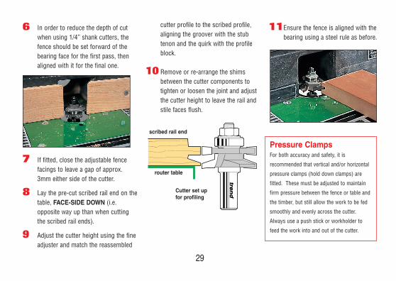
6 In order to reduce the depth of cutwhen using 1/4” shank cutters, thefence should be set forward of thebearing face for the first pass, thenaligned with it for the final one.
7 If fitted, close the adjustable fencefacings to leave a gap of approx.3mm either side of the cutter.
8 Lay the pre-cut scribed rail end on thetable, FACE-SIDE DOWN (i.e.opposite way up than when cuttingthe scribed rail ends).
9 Adjust the cutter height using the fineadjuster and match the reassembled
cutter profile to the scribed profile,aligning the groover with the stubtenon and the quirk with the profileblock.
10 Remove or re-arrange the shimsbetween the cutter components totighten or loosen the joint and adjustthe cutter height to leave the rail andstile faces flush.
11Ensure the fence is aligned with thebearing using a steel rule as before.
29
Pressure ClampsFor both accuracy and safety, it is
recommended that vertical and/or horizontal
pressure clamps (hold down clamps) are
fitted. These must be adjusted to maintain
firm pressure between the fence or table and
the timber, but still allow the work to be fed
smoothly and evenly across the cutter.
Always use a push stick or workholder to
feed the work into and out of the cutter.
router table
scribed rail end
Cutter set up for profiling
BOOK/PDS 2011 21/3/11 14:25 Page 31
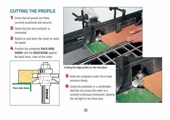
CUTTING THE PROFILE1 Check that all guards are fitted,
correctly positioned and secured.
2 Check that the dust extractor isconnected.
3 Switch on and allow the router to reachfull speed.
4 Position the workpiece FACE-SIDEDOWN with the FACE-EDGE againstthe back fence, clear of the cutter.
5 Slide the workpiece under the in-feedpressure clamp.
6 Using the pushstick or a workholder,feed the rail across the cutter in asmooth continuous movement, keepingthe rail tight to the fence face.
Cutting the edge profile on the trial piece
30
Face-side down
BOOK/PDS 2011 21/3/11 14:25 Page 32

31
When profile-scribing
curved and shaped
rails, it is advisable
to cut the scribed
joint before shaping the
rail edge. The rail edge can
then be cut to the required curve or
shape using a template/workholder, with
its leading (guide) edge cut to the
required curve or shape. For safe
handling, the workholder is fitted with
handles and/or guards and is initially
used to trim the rail against a bearing
guided trimming cutter.
A rear locating batten and lead-in and
lead-out end blocks, fitted to the
underside of the template, locate the
workpiece beneath the template.
The template must be cut overlength to
allow the cutter to be fed smoothly into
and away from the cutter. A lead-on pin
or piece should be fitted to the table to
prevent the end of the workpiece from
being snatched into the cutter.
Trimming the rail to shape:1 Roughly cut the rail to shape with a
jigsaw or bandsaw, taking care not todamage the scribed rail ends. Leavea maximum of 3mm for trimming.
2 Ensure that the rail is gripped in theworkholder, if necessary locating itwith veneer pins or double sided tape.
3 Fit a trimming cutter which has asuitable length of cut.
WORKHOLDER FOR TRIMMING
SHAPED RAILSWhen cutting curved andshaped rails, it is advisable tomake up a combined templateand workholder to ensuresafety and accuracy.
BOOK/PDS 2011 21/3/11 14:25 Page 33

Handle
Template
Back and end locating blocks
Handle
Router Table surface
Jig Template
Rail
RailLead-outblockLead-in
block
max. 3mm
4 A suitable guard must be fitted above the exposedcutter when carrying out any template profilingoperation.
5 Switch on and carefully feed the workholder ontothe cutter via the lead-on pin. Make a secondpass to ensure a clean cut has been produced.
32
BOOK/PDS 2011 21/3/11 14:25 Page 34

The sequence for cutting the profile on
shaped and curved rails and stile edges is
as follows:
1 Replace the trimming cutter with theprofile scribing cutter arranged to cutthe edge profile.
2 Use the pre-cut scribed rail end to setthe cutter height.
3 Re-fit the cutter guard and locate a trialworkpiece in the workholder, with theFACE-SIDE DOWN to the table (as foredge profiling straight rails).
4 Starting with the lead-in block of theworkholder resting against the lead-onpin, feed it into the cutter. Followthrough in a smooth continuousmovement along the length of the railand partially into the lead-out block.
5 Check that the trial piece produces aflush joint when assembled, beforecutting the remaining rails.
33
The curved rail edge after cuttingthe moulding and groove.
CUTTING THE EDGE PROFILE
BOOK/PDS 2011 21/3/11 14:25 Page 35

34
Profile scribed frames canbe fitted with either plain
or decorative moulded panelsmade from solid timber ortimber based sheet materials.However, all panels must be of stable
materials or constructed to eliminate any
excessive movement that may result in
twisting or warping of the panel and frame,
or shrinkage of the panel within the frame.
Panels must be of suitable thickness for
the overall frame size and have a finished
edge thickness that is a sliding fit in the
panel groove, but not too tight as it may
cause the rear groove edge to curl
outward.
Where the panel material is thicker than
the panel groove, the edge can be either
rebated on one or both faces, or raised and
fielded on the front face, using panel
raising cutters.
THEPANELS
PANEL STYLES _______________________ 35
JOINTING ________________________ 36 - 37
ASSEMBLING_________________ 38 - 39
TRIMMING______________________ 40 - 41
5
BOOK/PDS 2011 21/3/11 14:25 Page 36

35
Tongue and groovematch boardingEither v-jointed or with a beadprofile, the boarding can be cut to length and if thicker than thegroove, rebated to fit.
PANEL STYLES
Plain flat panels Cut from Medium DensityFibreboard (MDF), plywood orother timber based sheetmaterial. These materials caneither be veneered to matchthe frame timber or left plainfor painting.
Raised, fielded andmoulded panels These traditional panel boarderscan be simply cut using the routerfitted with a panel raising cutterselected from the Trend range.
Relief moulded Panels Cut from MDF sheet, these havea decorative relief moulding cutinto the surface, either to form aboarder parallel to the edges oras a pattern across the panelsurface. Panel moulding cuttersare used to machine themoulding, guided by a templateand guide bush, straight edge or the side fence.
BOOK/PDS 2011 21/3/11 14:25 Page 37

JOINTING
The four most commonmethods used for jointingpanels are traditionalrubbed joints, biscuitdowelled joints, rounddowelled joints and loosetongue joints.
Rubbed joints These are formed by planing the mating
edges perfectly straight and true before
applying glue and rubbing the two edges
together to spread the glue evenly. The
joint is then clamped until dry.
Biscuit Dowelling Biscuit or elliptical beech dowels, can be
used to reinforce edge-to-edge panel
joints. The dowels are set into semi-
circular recesses cut with the router fitted
with a suitable grooving cutter (See Trend
Biscuit Cutter Set, Ref. 342). The dowel
positions are carefully set out at approx
150mm centres along the joint faces, but
carefully avoiding the width of the panel
raising mould at each end of the panel.
36
BOOK/PDS 2011 21/3/11 14:25 Page 38

37
Round DowelsSmall diameter (6mm) round dowels are
inserted into equally spaced holes drilled
along the joint edges, using a proprietary
doweling jig. This ensures that the holes
are drilled at right angle to the edge and
correctly aligned. Lip and spur dowelling
drills, for use in drilling machines and
routers, and splined dowels (grooved to
allow excessive glue to be released) are
available from Trend.
GroovesA router can be used to cut grooves for
loose tongues, 6mm into each mating
edge, using either a narrow straight cutter,
guided by one or two side fences to centre
the cutter across the timber, or a ball
bearing guided grooving cutter. Stop the
groove clear of the panel mouldings at
each end to avoid showing the groove on
the face of the panel raising. Secure the
joint with a 10 mm wide cross grain
tongue, equal in thickness to the groove
width.
BOOK/PDS 2011 21/3/11 14:25 Page 39

When joining solid timberboards or strip, edge-to-edgeto form panels, alternate thedirection of the growth ringsto minimise cupping andbowing across the glued-upboard.
Preparing the TimberEach pair of mating edges must be
planed straight and square to ensure that
the joint will be virtually invisible and that
the panel will be flat when released from
the cramps.
Carefully arrange adjacent boards or
strips so that the grain pattern along the
joint lines blends and follows the same
direction. Alternatively arrange the grain
pattern to produce decorative book
matched or ‘flame’ pattern effects.
38
ASSEMBLY
Alternate growth ring direction of adjacent boards
Glued panelfinished toconsistentthickness
BOOK/PDS 2011 21/3/11 14:25 Page 40

In order to keep thin panels flat while
gluing and cramping:
1 Cut two pieces of thick sheet material
(MDF, Plywood, Chipboard etc.),
slightly smaller than the assembled
panel.
2 Cover the boards with polythene
sheet to prevent excess gluing
adhering to them.
3 Glue the edges and assemble the
panel on one board.
4 Lay the other board over it and
position cramps around the
perimeter, but do not fully tighten.
5 Use sash cramps or webbing straps
to pull the panel joints tight before
finally tightening the edge cramps.
6 When dry, release the cramps and
plane and/or sand the surface flat on
one face. Mark the finished panel
thickness along each edge and
plane/sand the other face.
Ensure that all traces of glue
are removed from both
surfaces.
Gluing and Cramping
39
BOOK/PDS 2011 21/3/11 14:25 Page 41

40
Assemble and clamp eachframe and measure the insidedimensions using a tapemeasure or by marking offalong a straight batten(setting out rod).
1 For solid timber frames and panels,
add to the length of the panel
(following the grain direction) twice
the depth of the panel groove minus
2mm. Add to the width of the panel
(across the grain) twice the depth of
the panel groove minus 6mm. This is
to allow for movement across the
width of the panel (the direction in
which most movement will occur)
while preventing it from dropping
vertically.
2 Alternatively a 6mm margin can be
deducted from both dimensions, but
this may require the panel to be fixed
in the panel grooves to prevent it
from dropping (see page 255).
CALCULATING THE PANEL SIZE
Groove depth: 46mm groover = 12mm41mm groover = 9.5mm
Always ensure that theedge thickness/profileproduces a sliding fit inthe groove.
For solid timber panelsallow: Rails 3mm
Stiles 1mmFor MDF or Plywood panelsallow 1mm clearance all round
BOOK/PDS 2011 21/3/11 14:25 Page 42

Panel margins for calculating overall panelsizes when using profile scribing cutterfitted with either 46 or 41mm groovers.
For solid timber panel:
46mm diameter groover = A = x + (2x12mm) - 6mmB or C = y1 or y2 + (2 x 12mm) - 2mm
41mm diameter groover = A = x + (2 x 9.5mm) - 6mmB or C = y1 or y2 + (2 x 9.5mm) - 2mm
For plywood or MDF(i.e. stable materials):
46mm diameter groover = A, B or C = x, y1 or y2 + (2 x 12mm) - 1mm
41mm diameter groover = A, B or C = x, y1 or y2 + (2 x 9.5mm) - 1mm.
41
Gra
in d
irect
ion
Shaped top panel
Square top panel
CB
A
y2 y1
x
Groove depth46mm groover = 12mm41mm groover = 9.5mm
3 Frames and panels made from stable
timber based materials (i.e. MDF) can
be cut to fit. These panels can then be
glued directly into the frames.
4 Plane one edge of the panel straight
and finish one end at right angles to it.
5 Transfer the dimensions then cut and
plane the panel to size, finishing the
edges square and parallel.
BOOK/PDS 2011 21/3/11 14:25 Page 43

42
6
The traditional panels for the doors can berouted using panel raising cutters held in a
fixed position router. The router can bemounted either overhead or inverted in a table.The material is then passed into the cutter in aseries of shallow passes to build up the mould.
VERTICAL _______________________ 43
BEARING _________________________ 44
HORIZONTAL _________________ 45
RADIUSED ______________________ 46
OGEE _________________________________ 47
OVOLO & CLASSIC _______ 48
BEVELLED _______________________ 49
RAISED PANELMOULDING CUTTERS
BOOK/PDS 2011 21/3/11 14:25 Page 44

43
When using vertical panel raising cutters
in inverted routers, it may be necessary
(not on Craftsman router table) to fit an
extended height false face to the back
fence, to support the workpiece vertically.
A deep horizontal front pressure guard or
vertical support will help ensure safety
and accuracy by keeping the bottom edge
of the workpiece flat against the fence
face.
VERTICAL RAISED PANEL CUTTERS
Positioning the vertical front support block
BOOK/PDS 2011 21/3/11 14:25 Page 45

44
Straight, or shaped panels can be
moulded (raised) by running the panel
against the ball bearing or the edge of a
template mounted above or below it.
However, the edge of the panel must be
finished as a smooth, continuous edge,
as the ball bearing will follow any
unevenness, repeating it on the finished
moulding. If required, the back fence can
be used when cutting straight edged
panels to provide additional stability.
When cutting curved work, the ball
bearing can be run against either the
shaped workpiece itself or against a
template (cut from 6.3mm thick material
(MDF, solid laminate etc.), fixed to the top
face of the workpiece with a purpose
made jig, pins or double sided tape.
Initially, templates can be cut using a
trammel or ellipse jig, relying on the
router cutter to leave a smooth square
edge. Alternatively, the template can be
cut with a jigsaw and the sawn edge
finished square with a plane or abrasive.
When using ball bearing guided cutters
on an inverted router table, it is necessary
to fit a false table top to allow the cutter
to sit fractionally below the surface. (See
page 247).
BEARING GUIDED RAISED PANEL CUTTERS
BOOK/PDS 2011 21/3/11 14:25 Page 46

45
Large diameter horizontal raised panel
cutters are used for moulding straight
edges against the table fence. It is
advisable to use them only in table
mounted variable speed routers at their
recommended safe speed.
Cutters above 50mm in diameter, should
be used at speeds not exceeding 18,000
rpm, above 70mm diameter at 16,000
rpm and above 80mm in diameter at
12,000 rpm.
When using horizontal
raised panel cutters, never
cut to the full depth in one
pass. The full depth
should be reached in a
series of shallow passes,
using the routers turret
stop to increase the cutting depth for
each. Likewise, wider mouldings can be
produced by resetting the fence to allow
the cutter to cut in a series of passes
cutting further in from the edge on each
pass. When using a router table with a
cutter aperture smaller than the cutter
diameter, always fit a false top to allow
the cutter to be set slightly lower than the
surface (see page 247).
HORIZONTAL RAISED PANEL CUTTERS
TABLE
FALSE TOP
1st PASS2nd PASS
SIDE FENCE
BOOK/PDS 2011 21/3/11 14:25 Page 47

46
RADIUSED PANEL MOULDING CUTTERS
RADIUSED PANEL MOULDING CUTTERS
18/81 40mm 86mm 12.7mm 1/2”
18/91 40mm 28.5mm 38mm 8mm & 1/2”
18/21 14mm 50mm 14mm 1/2”
18/18 50mm 73mm 22mm 1/2”
Ref. R D C Shank Diameter
Ref. 18/81
Ref. 18/18
Ref. 18/21
Ref. 18/91
CR
D
BOOK/PDS 2011 21/3/11 14:25 Page 48

47
OGEE PANEL MOULDING CUTTERS
Ref. 18/24
Ref. 18/25
Ref. 18/84
Ref. 18/83
OGEE PANEL MOULDING CUTTERS
18/24 12mm 50mm 14mm 1/2”
18/83 17.5mm 67mm 16mm 1/2”
18/23 6mm 50mm 14mm 1/2”
18/93 22mm 30mm 38mm 8mm & 1/2”
18/84 22.2mm 85.7mm 15.9mm 1/2”
18/25 3mm 50mm 14mm 1/2”
Ref. R D C Shank Diameter
Ref. 18/23
Ref. 18/93
d
CR
D
R
BOOK/PDS 2011 21/3/11 14:25 Page 49

48
MODERN OVOLO & CLASSIC MOULD
PANEL CUTTERS
Ref. 18/26
Ref. 18/92
Ref. 18/22
Ref. 18/82
MODERN OVOLO & CLASSIC MOULD PANEL CUTTERS
18/26 3° 6.3mm 3.2mm 45mm 13.5mm 8mm
18/82 5° 8mm 3mm 63.5mm 12.7mm 1/2”
18/22 - 3mm - 50mm 14mm 1/2”
18/92 85° 3mm 8mm 25.4mm 38mm 8mm & 1/2
Ref. A R1 R2 D C Shank Diameter
AR1R2
D
C
BOOK/PDS 2011 21/3/11 14:25 Page 50

49
BEVEL MOULD RAISED PANEL CUTTERS
Ref. 18/80
Ref. 18/19
Ref. 18/20
Ref. 18/90
BEVEL MOULD RAISED PANEL CUTTERS
18/80 15° 86mm 12.7mm 1/2”
18/90 75° 28.5mm 38mm 8mm & 1/2”
18/20 10° 50mm 17mm 1/2”
18/19 25° 69mm 19mm 1/2”
Ref. A D C Shank Diameter
A
D
C
BOOK/PDS 2011 21/3/11 14:25 Page 51

50
7 Raised panel cutters areused to cut away the
panel edge to fit into therail or stile groove,producing a decorativebevel, radius, ogee orovolo moulding.
SETTING UP______________________________ 51
MAKING A TEMPLATE _________ 52
COMBINED JIG ______________________ 54
SCORING __________________________________ 55
LEAD-ON PIECE _____________________ 56
USINGRAISED PANEL CUTTERS
BOOK/PDS 2011 21/3/11 14:25 Page 52

51
Before using cutters larger indiameter than the router tableaperture, it may be necessaryto lay a false top over therouter table, to allow thebottom of the cutting edgesto be set lower than the tablesurface.
1 Cut a piece of 6 to 12mm medium
density fibreboard (MDF) to the same
size as the table top.
2 Place it over the router table top and
mark out any existing holes that can
be used to fasten the false top. If not,
set out two suitable positions to take
fixing bolts.
3 Drill and counter-bore the fixing holes
in the false top to match the holes in
the existing top.
4 Mark the centre point of the existing
table cutter aperture on the false top
and drill/cut fixing holes or slots for
the existing back fence.
5 Add 6mm to the diameter of the
cutter and cut the cutter aperture to
that diameter.
6 Fasten the false top on the table.
7 With the router disconnected from
the power source and the fence
removed, fit the cutter from above,
ensuring that there is a minimum of
three quarters of the shank length
held in the collet and that the bottom
edges are set fractionally below the
surface of the false top (not touching
the router table).
8 Refit the back fence (replacing the
mounting bolts with longer ones as
necessary) and mount the holding
down guards. Check that all are
correctly adjusted and secure.
SETTING UP
TABLE
FALSE TOP
BOOK/PDS 2011 21/3/11 14:25 Page 53

52
MAKING ATEMPLATE
For accuracy, curved and shapedpanels should be cut using atemplate cut to fit into the frame.This reduces the risk of ruining theactual panel material and speedsup the work when cutting severalor a batch of similar panels.
1 Clamp the dry assembled door frame
over a piece of 6mm thick sheet
material (plywood, MDF etc.) and
check that it is square and flat.
2 Carefully draw round the inside edge.
4 Carefully cut around the outer line
with a jigsaw, or for regular curves,
with the router fitted with a beam
trammel.
3 To the outline drawn on the template
material, add the required groove
width (see page 228) and draw a line
outside and parallel to the outline.
BOOK/PDS 2011 21/3/11 14:25 Page 54

5 Finish the straight edges with a plane and the
curved or shaped edges with a spokeshave or
abrasive. Check that all edges are smooth, as any
unevenness will be repeated on the finished work
when trimming with a ball bearing guided cutter.
6 Check that the margins are correct by
re-assembling the frame, with the template fitted.
7 Lay the template on the uncut panel and mark out
the outline.
8 Cut the panel roughly to shape with a jigsaw or
band saw.
TRIMMING TO SIZE
9 Trim the panel flush to the template edge using a ball
bearing guided template profiling cutter. Although the
router is shown fitted to an inverted router table, it can also
be used for trimming in hand-held mode.
BOOK/PDS 2011 21/3/11 14:25 Page 55

54
COMBINED JIG
A combined jig for cuttingboth the rail and panel shapecan be made, consisting oftwo matching templates fittedto a baseboard.
Templates can be cut from Birch multi-
core plywood, MDF or preferably solid
laminate sheet to the required shape or
curve. For safety and accuracy extend
the curve either side of the required
length or shape. These lead-in and out
sections, allow the cutter to enter and
leave the work smoothly without
snatching. The template can be pinned
to the component into the waste of the
stub tenon to avoid marring the face of
the wood. Cut the curved rail/panel
using a ball bearing guided straight
profiling cutter.
BOOK/PDS 2011 21/3/11 14:25 Page 56

After trimming and squaring the panels, select
and mark the face side. Whether cutting
straight, curved or shaped edges, always cut
the raised edge moulding, first across the grain
before cutting the moulding along it. This will
remove any break out left by the cross grain
cut.
If the cutter persists in tearing the grain, score
across the cut line with a sharp knife, the width
of the cutter in from the edge of the workpiece
(i.e. distance from the outer tip of the cutter to
the bearing or fence).
Scoring across theend grain
SCORING
55 trend routing technology
BOOK/PDS 2011 21/3/11 14:25 Page 57

When moulding curved or shaped raised
panel edges, using ball bearing guided
cutters, a lead-on pin (as on our
Craftsman table) or lead-on piece, must
be fitted to prevent the work from being
snatched into the cutter.
A lead-on piece can be cut in the
workshop from waste plywood or
hardwood and securely mounted on the
router table (or the false top). The lead-
on piece should be fitted close to the
cutter to provide a rest or pressure block
so that the workpiece can be steadied
against as it is fed into the cutter. A
lead-off piece can also be fitted to
support the work as it leaves the cutter.
LEAD-ON PIECE Top Guard Panel Cutter
Lead-on piece
Adjusting screws andmounting brackets
56
Feed Direction
BOOK/PDS 2011 21/3/11 14:25 Page 58

57
Preparation:
● Always use guards to ensure there isno possibility of fingers contactingthe cutter should your grip slip or thecutter snatch.
● If in doubt always take more shallowpasses rather than fewer deeper cuts.
● Reduce the speed of the router whenusing cutters over 50mm in diameter.
● Use a lead-on pin when carrying outcurved work.
● Measure twice cut once.● Take care when handling cutters as
they are sharp and can easily causeinjury.
● Always switch off the router andisolate from the mains supply beforechanging cutters or makingadjustments to the router, table ormachining set-up.
● Before reconnecting to the supply,make sure that the power switch is inthe OFF position (fit a no-volt release
switch to inverted or overheadtables).
● Ensure that all power leads are clearof the table and cutter. Check theycannot catch on the work orworkholder or interfere with themovement of, or trip the operator.
● Always wear eye protection such asgoggles or a full face visor. Alwayswear ear defenders particularly ifrouting for lengthy periods.
● Do not wear loose clothing orjewellery that can catch or snag oncutters or equipment. Always tieback long hair.
Final checks:● Check that all guards are correctly
and securely fitted. ● Check that the dust extraction is
connected.● Check that the cutter is correctly
fitted (i.e. at least 3/4 of the shank
length is held in the collet).● Ensure groovers are correctly
assembled and nut is tight.● Practice the cutting procedure before
switching on the router.● Keep fingers clear of the cutter and
never touch the router or cutter toslow the machine down.
● Do not switch on the router with theworkpiece in contact with the cutter.
● Always feed the timber into cutter tooppose the direction of the cutter.
SUMMARY OF SAFETY TECHNIQUES
Back fence
Cutter Rotation
Timber Feed
BOOK/PDS 2011 21/3/11 14:25 Page 59

Before gluing the work together, assemble
the frame dry and mark each piece of each
joint for easy reference.
1 Check that the panels will fit into the
grooves without being forced, otherwise
the whole door will be difficult to
assemble and edges may split away.
2 All of the surfaces that cannot easily be
sanded after assembly, should be
finished before gluing up. Be careful
when sanding the inside edges that the
location marks for the rails are not
sanded away.
3 Prior to gluing, place battens across the
top of the bench for the door to rest on.
This will allow the cramps to be
positioned far more easily. The top edge
of the battens must be perfectly level in
order that the door will be flat when
cramped.
8 Care and attention isessential when gluing and
assembling doors, in order thatthey remain square and truewhen fitted. Always apply gluesparingly to avoid leavingtraces on surfaces that are tobe varnished.
DOORASSEMBLY
58
BOOK/PDS 2011 21/3/11 14:25 Page 60

59
Gluing the panelsUnless made of MDF or other stable
material, panels should not be glued into
the frame. However, it is possible to
secure timber panels with two brass
veneer pins at the centre or each rail.
This allows for movement of the timber
while the pins prevent the panel rattling
in the frame should it shrink.
Pinning the panelDo take care when inserting pins, not to
split the thin groove edge. Preferably
drill fine pilot holes and drive the pins at
an angle into the thicker part of the edge
moulding. File and punch the pins below
the surface. As an allowance has been
made for the panel to move, make sure it
is centred and square before pinning it
into the frame.
Clamping1 To protect the surface from the
cramp jaws, insert ply packing or a
continuous batten between the cramp
heads and door edge. To stop the
bar of the cramp scuffing the face of
the door insert a thin piece of
plywood along each stile.
2 Before leaving the glue to set, check
that the door is square, by measuring
across the diagonals and checking
that it has no twist, using winding
strips to sight along it.
Finishing If the doors are to be given a clear finish,
it is very important not to leave traces of
glue on the surface. When gluing the
joints together try to judge the amount of
glue used so that it just forms a thin line
on the surface that can be cut off later. If
the glue runs onto the surface thoroughly
wipe this away with a damp cloth making
sure that the glue is completely removed
from the grain as well as the surface. If
this is not done properly any stain or
polish subsequently applied may
highlight the area in the form of a white
stain.
BOOK/PDS 2011 21/3/11 14:25 Page 61

60
The size and type of hinge chosen will
depend on the size and weight of the
door itself. With flap hinges the
thickness of the door style in relation to
the flap width will dictate the hinge size
used. Economy lay-on hinges are only
suitable for lightweight doors up to
450mm wide. Concealed hinges will
support larger and heavier doors and are
fully adjustable once fitted.
Flap hingesTraditional solid drawn or plated flap
hinges can be used where the door is set
flush into the cabinet carcass. Flap
hinges are set into recesses cut in the
cabinet side and door stile. These
recesses can again be cut with the
router, using a simple template and guide
bush.
Lay-on hingesLay-on hinges are commonly used for
economy cabinet construction, being
simply screwed to the inside face of the
cabinet or frame and the stile edge.
HINGES
Router fitted withstraight cutter
Guide Bush fitted to base of router
Cramp
Hinge Template cut from6mm MDF and screwedto clamping batten
BOOK/PDS 2011 21/3/11 14:25 Page 62

61
Concealed hinges The type of hinge used on doors depends
on the construction of the cabinet, its
location and use. When used on kitchen
and other fitted cabinets, where the door
covers part or all of the cabinet frame, it
is common practice to use concealed
hinges.
These are generally designed to open to
an angle of 100 degrees, although special
lay back examples allow the doors to
open clear of the cabinet sides to allow
unrestricted access. These hinges have
a circular boss that is sunk into the door
panel and are available in either plain or
sprung versions. The latter eliminates
the need for a separate catch or lock.
They are available with various boss
diameters, although 35mm is the most
common.
Fall Flap hinges Fall flap hinges (as used on desks and
light duty work flaps) are fitted in a
similar way to concealed hinges, using a
template to position the cutter over the
face edge of the door and carcass.
Our new range of machine bits are for use in
portable plunge routers. These specially
designed machine bits have a new form of
scriber to allow use at high speeds, Max.
20,000 RPM. For accurate repetitive routing, a
template and guide bush fitted to the router
base should be used. Ref. 105 group.
Machining the holes
BOOK/PDS 2011 21/3/11 14:25 Page 63

62
Where cabinet doors are to be fitted to
the face of the carcass or frame, a further
attractive effect can be achieved by
routing a chamfer or decorative moulding
around the outer edges.
Choose a moulding of similar style to the
profile moulding cutter and/or raised
panel cutter and of similar size.
Edge moulding can be quickly carried out
with cutters guided by the side fence or
using ball bearing guided cutters.
When edge routing doors with raised
panels that are higher than the frame
face, it is advisable to fit a packing piece
to the underside of the router to support
it on the frame face rather than the panel
face. When using the side fence, it is
advisable to extend the fence facings
(cheeks), in order to prevent the cutter
from turning in as it starts and finishes
the cut at each end of the stile or rail.
Edge moulding using a side fence.
Ref. 7/4 Ref. 46/41 Ref. 7/81 Ref. 22/01 Ref. 19/62
EDGE MOULDING
BOOK/PDS 2011 21/3/11 14:25 Page 64

BO
OK
/PD
v2.
1
Trend Machinery & Cutting Tools Ltd.Odhams Trading Estate St Albans RoadWatford WD24 7TR EnglandTel: 0044(0)1923 [email protected]
BOOK/PDS 2011 21/3/11 14:25 Page 65