how good are axle non-destructive testing techniques?
TRANSCRIPT

Copyright © TWI Ltd 2011
How good are axle non-destructive testing techniques?
John Rudlin TWI
ESIS TC 24 3/4 March 2011

Copyright © TWI Ltd 2011
Content
• Methods of NDT for Fatigue cracks• Capabilities • Inspection for Corrosion?
ESIS TC 24 3/4 March 2011

Copyright © TWI Ltd 2011
Methods of Axle NDT
• Visual• Surface Accessible
– MPI– Eddy Current– ACFM– Ultrasonics
• Sub-Surface or Non-accessible– Ultrasonics
• Latest Developments
ESIS TC 24 3/4 March 2011

Copyright © TWI Ltd 2011
MPI
ESIS TC 24 3/4 March 2011

Copyright © TWI Ltd 2011
MPI
• Carried out at overhaul with wheels removed (so inspects normally inaccessible areas)
• Clean (grit blasted) surface ideal• Bench Unit• Visual indication of crack• Operator Dependent (equipment set
up/interpretation/alertness)
ESIS TC 24 3/4 March 2011

Copyright © TWI Ltd 2011
Eddy Current Probes
ESIS TC 24 3/4 March 2011

Copyright © TWI Ltd 2011
Eddy Current Signal (2mm deep crack)
ESIS TC 24 3/4 March 2011

Copyright © TWI Ltd 2011
Eddy Current/ACFM
• Can be carried out on exposed surfaces with axles in-situ
• Requires “small” probe to scan surface• Can scan though non-conductive
coatings/with minimum cleaning• Visual/audible indication from instrument• Requires operator to have manual
dexterity as well as interpretation skills and alertness
ESIS TC 24 3/4 March 2011
Copyright © TWI Ltd 2011
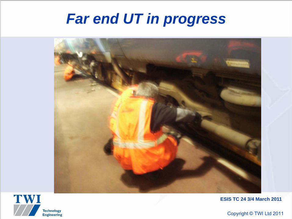
Far end UT in progress
ESIS TC 24 3/4 March 2011
Copyright © TWI Ltd 2011
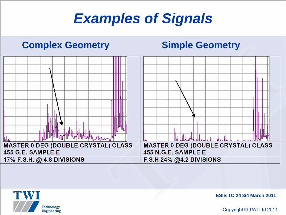
Examples of Signals
Complex Geometry Simple Geometry
ESIS TC 24 3/4 March 2011

Copyright © TWI Ltd 2011
Ultrasonics (exposed and non-exposed surfaces)
• Scans from axle end (far end test, near end test)
• From axle body (high angle scan, internal bore scan)
• Requires clean surfaces and applied couplant
ESIS TC 24 3/4 March 2011

Copyright © TWI Ltd 2011
Ultrasonics (exposed and non-exposed surfaces)
• Detection of cracks subject to skew and tilt relative to ultrasonic beam (probe and frequency), gape of crack and axle geometry
• Generally poorer detection capability than surface methods
• Manual operation highly skilled –automation introduced for some cases

Copyright © TWI Ltd 2011
Performance Assessment
• Usually needed as probability of detection (POD) curves
• False Calls also important• Can be assessed by:
– Anecdotal evidence– Expert opinion– Measurement of Indications– Inspection Reliability Trials
ESIS TC 24 3/4 March 2011

Copyright © TWI Ltd 2011
MPI
• Difficult to measure (frequently used as reference)
• Expectation of crack detection less than 1mm deep on good surfaces
• Sometimes false calls from scratches/machining marks
ESIS TC 24 3/4 March 2011

Copyright © TWI Ltd 2011
Eddy Current
• Sensitivity approaches MPI
• Cracks of 1mm deep can be expected to give 100% screen height signal with around 20% noise from surface
• (Unable to produce POD in WIDEM because 90% POD was less than 1mm crack depth)
ESIS TC 24 3/4 March 2011

Copyright © TWI Ltd 2011
Far End PODs – Simple Geometry, 0° probeFitted model for Group 1 axles inspected with 0° probe
0%10%20%30%40%50%60%70%80%90%
100%
0 5 10 15 20 25Crack depth (mm)
Prob
abili
ty o
f det
ectio
n
Op COp DOp EOp FOp GRA (non-blind)
ESIS TC 24 3/4 March 2011
Copyright © TWI Ltd 2011
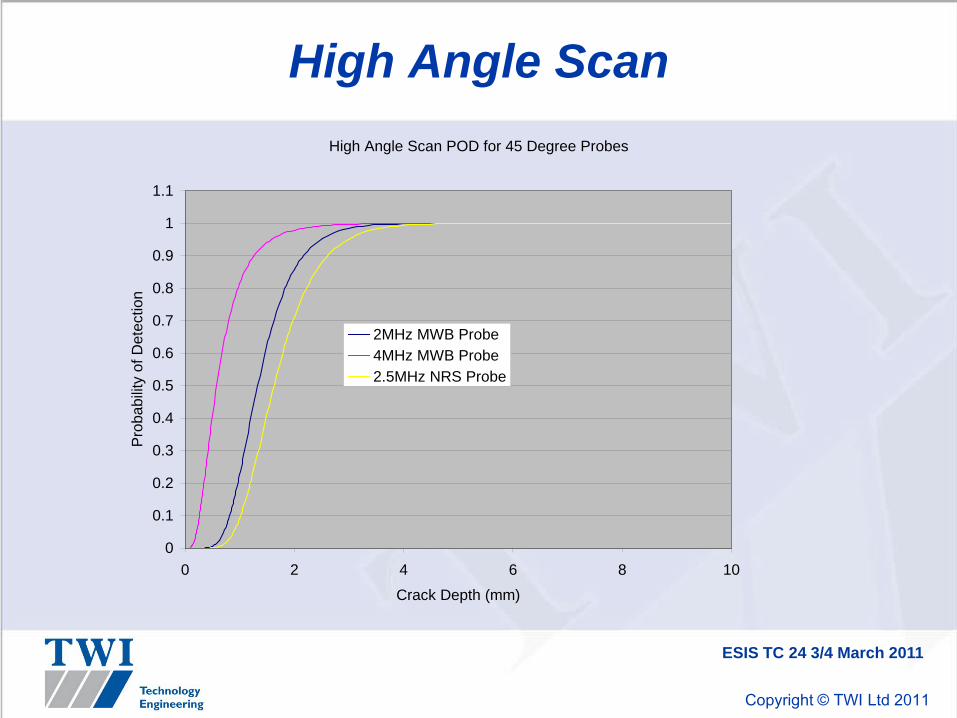
High Angle ScanHigh Angle Scan POD for 45 Degree Probes
0
0.1
0.2
0.3
0.4
0.5
0.6
0.7
0.8
0.9
1
1.1
0 2 4 6 8 10
Crack Depth (mm)
Prob
abilit
y of
Det
ectio
n
2MHz MWB Probe4MHz MWB Probe2.5MHz NRS Probe
ESIS TC 24 3/4 March 2011

Copyright © TWI Ltd 2011
Hollow axle Bore InspectionPOD for Hollow Axle Inspection (10% threshold)
0
0.1
0.2
0.3
0.4
0.5
0.6
0.7
0.8
0.9
1
0 5 10 15 20 25
Crack Depth (mm)
Prob
abilit
y of
Det
ectio
n
45 degree probe (one side)38 degree probe (one side)
ESIS TC 24 3/4 March 2011

Copyright © TWI Ltd 2011
New UT: Phased Array
• Produces electronically scanned beam and image of any flaws
• Easier for operator interpretation?Automatic scanning to reduce operator error
ESIS TC 24 3/4 March 2011

Copyright © TWI Ltd 2011
Conclusions for fatigue cracks
• For surface flaws surface methods give best results
• For UT inspection best results from high angle type inspections if possible
• Always bear in mind the effect of crack and component geometry and interaction with UT beams
• Human factors affect all techniques (even automated techniques have to be set up and checked to establish reliability)
ESIS TC 24 3/4 March 2011

Copyright © TWI Ltd 2011
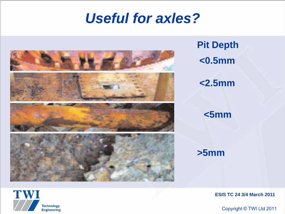
Assessment of Corrosion
• Currently visual inspection only – highly qualitative
• Reference standards? Pit gauge?
ESIS TC 24 3/4 March 2011
Copyright © TWI Ltd 2011
Useful for axles?
ESIS TC 24 3/4 March 2011
<0.5mm
<2.5mm
Pit Depth
<5mm
>5mm

Copyright © TWI Ltd 2011
Corrosion fatigue
• Corrosion fatigue more subtle than this!
• What to measure?– Remaining thickness?– Surface roughness/shape parameters early
crack initiation at low loads or ?– Changes over time?
• How to measure?– Optical/electromagnetic/other
ESIS TC 24 3/4 March 2011

Copyright © TWI Ltd 2011
WOLAXIM Project
• EU funded R4SME project developing 3 new NDT techniques-one of which is a to develop an instrument for corrosion assessment related to risk of crack growth
• www.wolaxim.eu
• Also EURAXLES project
ESIS TC 24 3/4 March 2011

Copyright © TWI Ltd 2011
Copyright
Presentation prepared for xxx by TWI under Project No. yyy
TWI holds copyright on this presentation.
All rights reserved. No part of this presentation may bereproduced or transmitted in any form or by any means,
electronic or mechanical, including photocopy, recording,or any information storage and retrieval system, without
the express permission of TWI.
ESIS TC 24 3/4 March 2011