hot water boiler sizes 125,000 through 200,00 series a...
TRANSCRIPT

BW9
Installation Instructions
Gas---Fired, Direct Vent, Condensing
Hot Water Boiler
Sizes 125,000 Through 200,00
Series A
NOTE: Read the entire instruction manual before starting theinstallation.
PAGE
SAFETY CONSIDERATIONS 1. . . . . . . . . . . . . . . . . . . . . . . .
INTRODUCTION 2. . . . . . . . . . . . . . . . . . . . . . . . . . . . . . . . . .
INSTALLATION 3. . . . . . . . . . . . . . . . . . . . . . . . . . . . . . . . . . .
Rules for Safe Installation and Operation 3. . . . . . . . . . . . .
Before Installing the Boiler 3. . . . . . . . . . . . . . . . . . . . . . . .
Placing the Boiler 5. . . . . . . . . . . . . . . . . . . . . . . . . . . . . . .
Near Boiler Piping 5. . . . . . . . . . . . . . . . . . . . . . . . . . . . . .
Combustion Air and Vent Pipe 6. . . . . . . . . . . . . . . . . . . . .
Gas Supply Piping 10. . . . . . . . . . . . . . . . . . . . . . . . . . . . .
Controls and Accessories 14. . . . . . . . . . . . . . . . . . . . . . . .
START--UP AND CHECK--OUT PROCEDURES 15. . . . . . . .
Water Treatment and Freeze Protection 15. . . . . . . . . . . . . .
Filling Boiler With Water and Purging Air forSystems With Diaphragm Type Expansion Tanks 17. . . . . .
Filling Boiler With Water and Purging Air forSystems With Conventional Closed TypeExpansion Tanks 17. . . . . . . . . . . . . . . . . . . . . . . . . . . . . . .
Placing Boiler in Operation 18. . . . . . . . . . . . . . . . . . . . . . .
Check Out Procedures and Adjustments 18. . . . . . . . . . . . .
CARE AND MAINTENANCE 20. . . . . . . . . . . . . . . . . . . . . . .
SERVICE HINTS AND TROUBLESHOOTING 23. . . . . . . . .
REPAIR PARTS 35. . . . . . . . . . . . . . . . . . . . . . . . . . . . . . . . . . .
SAFETY CONSIDERATIONS
Installing and servicing heating equipment can be hazardous dueto gas and electrical components. Only trained and qualifiedpersonnel should install, repair, or service heating equipment.Untrained personnel can perform basic maintenance functionssuch as maintaining water level. All other operations must beperformed by trained service personnel. When working onheating equipment, observe precautions in literature, on tags, andon labels attached to or shipped with unit and other safetyprecautions that may apply.
Recognize safety information. This is the safety--alert symbol. When you see this symbol on the unit and in instruction
manuals, be alert to the potential for personal injury.
Understand the signal words DANGER, WARNING,CAUTION, and NOTE. These words are used with thesafety--alert symbol. DANGER identifies the most serioushazards which will result in severe personal injury or death.
WARNING signifies hazards which could result in personalinjury or death. CAUTION is used to identify unsafe practiceswhich may result in minor personal injury or product andproperty damage. NOTE is used to highlight suggestions whichwill result in enhanced installation, reliability, or operation.
amaCERTIFIED
®ASME
Read and obey the following rules to ensure safe installation andoperation:
1. Read the entire installation manual before beginning theinstallation. Failure to follow these rules of safeinstallation and operation and these instructions couldcause a malfunction of the boiler and result in death,serious bodily injury, and/or property damage.
2. Check all applicable state and local building codes andutility company requirements before installation. Theinstallation must conform with these requirements in theirentirety. In the absence of these codes, use NFPAInstallation Codes and good industry practices.
3. Before servicing the boiler, allow boiler to cool. Alwaysshut off any electricity and gas supply connected to theboiler prior to servicing.
4. Inspect gas line for leaks.
5. Be certain gas input rate is correct. Overfiring may resultin early failure of boiler sections. This may causedangerous operation. Underfiring may result in too muchair for the pre--mix burner causing poor combustion orloss of combustion.
6. Never vent the products of combustion from this boiler toan enclosed space. Always vent to the outdoors. Nevervent to another room or to inside a building.
7. Be sure there is adequate air supply to boiler for completecombustion.
8. Follow a regular service and maintenance schedule forefficient and safe operation.
9. Keep boiler area clean and free from combustible andflammable materials.
2
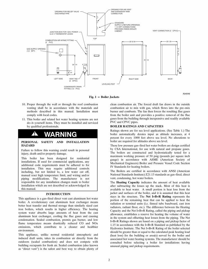
25 1/4
6 1/4
LEFT SIDE FRONT
COMBUSTION AIR INTAKE FITTING(2� PVC)
JUNCTION BOX FOR 120V. POWER& 24 V THERMOSTAT LEADS
VENT TEE(2� CPVC)
4 7/16
TOP
OPENING FOR RELIEF VALVEDISCHARGE PIPE
OPENING FOR AIR VENTAND EXPANSION TANKCONNECTION
STANDARDSUPPLY & RETURN OPENINGS1 1/4 NPT CONNECTIONSPROVIDED INSIDE BOILER CABINET.
32 5/16
40 1/4
CONDENSATE DRAINFITTING (1/2� PVC)
LEVELING FEET
RIGHT SIDE BACK
VENT CONNECTION (2� CPVC)
20 1/8
GAS SUPPLY OPENING(1/2� NPT)
A04049
Fig. 1 --- Boiler Jackets
10. Proper through the wall or through the roof combustionventing shall be in accordance with the materials andmethods described in this manual. Installation mustcomply with local codes.
11. This boiler and related hot water heating systems are notdo--it--yourself items. They must be installed and servicedby qualified professionals.
PERSONAL SAFETY AND INSTALLATIONHAZARD
Failure to follow this warning could result in personalinjury, death and/or property damage.
This boiler has been designed for residentialinstallations. If used for commercial applications, anyadditional code requirements must be adhered to forinstallation. This may require additional controlsincluding, but not limited to, a low water cut off,manual reset high temperature limit, and wiring and/orpiping modifications. The manufacturer is notresponsible for any installation changes made to boilerinstallation which are not described or acknowledged inthis manual.
! WARNING
INTRODUCTION
This appliance is a gas--fired direct vent cast aluminum hot waterboiler. A revolutionary cast aluminum heat exchanger meansbetter heat transfer and thermal storage than similarly sized castiron boilers, which results in higher efficiency. The heatingsystem water absorbs large amounts of heat from the castaluminum heat exchanger, cooling the flue gases and causingcondensation. Sealed combustion, premix gas burner, and lowflame temperature means drastically reduced CO and NOxemissions, which contribute to a cleaner and healthierenvironment.
This appliance, unlike normal residential atmospheric andinduced draft units, takes its combustion air directly from theoutdoors (sealed combustion) and does not compete withbuilding occupants for fresh air. Sealed combustion (also knownas “direct vent”) is the safest and best way to obtain plenty of
clean combustion air. The forced draft fan draws in the outsidecombustion air to mix with gas, which flows into the pre--mixburner and combusts. The fan then forces the resulting flue gasesfrom the boiler unit and provides a positive removal of the fluegases from the building through inexpensive and readily availablePVC and CPVC pipes.
BOILER RATINGS AND CAPACITIESRatings shown are for sea level applications. (See Table 1.) Theboiler automatically derates input as altitude increases, at 4percent for every 1000 feet above sea level. No alterations toboiler are required for altitudes above sea level.
These low pressure gas--fired hot water boilers are design certifiedby CSA International, for use with natural and propane gases.The boilers are constructed and hydrostatically tested for amaximum working pressure of 50 psig (pounds per square inchgauge) in accordance with ASME (American Society ofMechanical Engineers) Boiler and Pressure Vessel Code SectionIV Standards for heating boilers.
The Boilers are certified in accordance with ANSI (AmericanNational Standards Institute) Z21.13 standards as gas--fired, directvent, condensing, hot water boilers.
The Heating Capacity indicates the amount of heat availableafter subtracting the losses up the stack. Most of this heat isavailable to heat water. A small portion is heat loss from thejacket and surfaces of the boiler, and it is assumed that this heatstays in the structure. The Net I=B=R Rating represents theportion of the remaining heat that can be applied to heat theradiation or terminal units (i.e. finned tube baseboard, cast ironradiators, radiant floor, etc.). The difference between the HeatingCapacity and the Net I=B=R Rating, called the piping and pickupallowance, establishes a reserve for heating the volume of waterin the system and offsetting heat losses from the piping. The NetI=B=R Ratings shown are based on a piping and pickup factor of1.15 in accordance with the I=B=R Standard as published by theHydronics Institute. The Net I=B=R Rating of the boiler selectedshould be greater than or equal to the calculated peak heating load(heat loss) for the building or area(s) served by the boiler andassociated hot water heating systems. The manufacturer should beconsulted before selecting a boiler for installations havingunusual piping and pickup requirements.

3
Table 1—Sea Level Ratings--Natural and Propane Gases
MODEL INPUT* (MBH){HEATINGCAPACITY*(MBH)
NET I=B=RRATING* (MBH)
SHIPPINGWEIGHT (LBS) }AFUE FLUE DIAM.
125 125 112.5 98 284 90 2” CPVC and 3”PVC
150 150 135 117 284 90 2” CPVC and 3”PVC
175 175 157.5 137 284 90 2” CPVC and 3”PVC
200 200 180 157 284 90 2” CPVC and 3”PVC
*1 MBH = 1,000 BtuhBtuh = British Thermal Units per Hour{ AFUE (Annual Fuel Utilization Efficiency) and Heating Capacity is based on the D.O.E. (Department of Energy) test procedureRatings shown are for sea level applications. The boiler automatically derates input as altitude increases (See Table 6 and 7 for the approximate rate at givenaltitudes). No alterations to boiler are required for altitudes above sea level.
INSTALLATION
STEP 1 —Rules for Safe Installation and Operation1. Read the entire installation manual before beginning theinstallation. Failure to follow these rules for safeinstallation and operation and these instructions couldcause a malfunction of the boiler and result in death,serious bodily injury, and/or property damage.
2. Check all applicable state and local building codes andutility company requirements before installation. Theinstallation must conform with these requirements in theirentirety. In the absence of these codes, use NFPAInstallation Codes and good industry practices.
3. Before servicing the boiler, allow the boiler to cool.Always shut off any electricity and gas supply connectedto the boiler prior to servicing.
4. Inspect gas line for leaks.
5. Be certain gas input rate is correct. Over firing may resultin early failure of the boiler sections. This may causedangerous operation. Under firing may result in too muchair for the pre--mix burner causing poor or loss ofcombustion. A combustion analyzer is required toproperly determine the correct firing rate.
6. Never vent the products of combustion from this boiler toan enclosed space. Always vent to the outdoors. Nevervent to another room or to inside a building.
7. Be sure there is adequate outdoor air supply to boiler forcomplete combustion.
8. Follow a regular service and maintenance schedule forefficient and safe operation.
9. Keep boiler area clean of debris and free of combustibleand flammable materials.
10. Proper through the wall or through the roof combustionventing shall be in accordance with the materials andmethods described in this manual. Installation mustcomply with local codes.
11. This boiler and related hot water heating systems are notdo it yourself items. They must be installed and servicedby qualified professionals.
STEP 2 —Before Installing the BoilerComplete all of the following prior to installing the boiler.
CODES
This boiler product is a gas--fired, direct vent, condensing boilerand must be installed in accordance with all applicable federal,state and local building codes including, but not limited to thefollowing:
United States -- Installation shall conform with National FuelGas Code (NFPA--54/ANSI Z223.1-- latest edition)
Canada -- Installation shall be in accordance with CSA--B149.1and .2 installation codes.
Where required by the authority having jurisdiction, theinstallation must conform to the American Society of MechanicalEngineers Safety Code for Controls and Safety Devices forAutomatically Fired Boilers, No. CSD--1.
The installation must conform to the requirements of theauthority having jurisdiction or, in the absence of suchrequirements, to the National Fuel Gas Code, ANSI Z223.1 --latest revision.
Installers -- Follow local regulations with respect to installationof CO (Carbon Monoxide) Detectors. Follow maintenancerecommendations in this manual.
BOILER SIZING
Check to be sure you have selected the boiler with the propercapacity before continuing the installation. The I=B=R Rating ofthe boiler selected should be greater than or equal to thecalculated peak heating load (heat loss) for the building or area(s)served by the boiler and associated hot water heating systems.(See Table 1.)
Heat loss calculations should be based on approved industrymethods.
CONSIDERATIONS FOR BOILER LOCATION
Before selecting a location for the boiler, the following should beconsidered. Each boiler considered for installation must be:
S Supplied with the correct type of gas (natural gas orpropane).
S Connected to a suitable combustion air intake pipingsystem to supply the correct amounts of fresh (outdoor)air for combustion (maximum length 60 ft).
S Connected to a suitable venting system to remove thehazardous products of gas combustion (maximumlength 60 ft).
S Connected to a suitable hot water heating system.
S Supplied with a suitable electrical supply for all boilermotors and controls.
S Connected to a properly located thermostat or operatingcontrol (not included with boiler).
S Placed on level surface (must NOT be installed oncarpeting).
S Condensate drain line must be pitched down to floordrain or external condensate pump with reservoir at 1/4in. per foot (wood frame or blocks may be used to raiseboiler).

4
Table 2—Boiler Clearances (In.)
UNIT COMBUSTIBLECONSTRUCTION
ACCESSIBILITY/CLEANING SERVICING
Top 1 8 8Left Side 8 24 24Right Side 1 --- ---Base 1 --- ---Front 0 24 24Back 1 --- ---
Intake/Vent Piping 0 --- ---Near Boiler Hot Water Piping 1 --- ---
LOCATING THE BOILER
All distances measured from the cabinet of the boiler. (See Table2.)
1. Select a location which is level, central to the pipingsystems served and as close to the vent and air intaketerminals as possible.
2. Accessibility clearances, if more stringent (i.e. largerclearances) than required fire protection clearances, mustbe used for the boiler installation. Accessibility clearancesmay be achieved with the use of removable walls orpartitions.
3. The boiler is approved for installation in closets and oncombustible floors. This boiler shall NOT be installed oncarpeting.
4. The clearances shown in Table 2 indicate requiredclearances per CSA listing. A minimum 1 in. clearancemust be maintained between combustible construction andeach of the right, top and back surfaces of the boiler. Aminimum 8” clearance is required on the left side,to allow room for the inlet air pipe. An 18” clearance mustbe maintained at the front where passage is required forcleaning or servicing, inspection or replacement of anyparts that normally may require such attention. Allow atleast 24” at the front and left side and 8” at the top forservicing. No combustible clearances are required toventing or combustion air intake piping.
5. Equipment shall be installed in a location which facilitatesthe operation of venting and combustion air intake pipingsystems as described in this manual.
6. Advise owner of boiler to keep venting and combustionair intake passages free of obstructions. Both the ventingand combustion air intake piping systems connected to theoutdoors must permit flow through the piping systemswithout restrictions for the boiler to operate.
7. The boiler shall be installed such that the automatic gasignition system components are protected from water(dripping, spraying, rain, etc.) during operation andservice (circulator replacement, control replacement, etc.).
8. The boiler must be located where ambient temperatures(minimum possible room air temperatures where boiler isinstalled assuming boiler is not in operation and thereforecontributes no heat to the space) are always at or above 32degrees F to prevent freezing of liquid condensate.
COMBUSTION AND VENT PIPE REQUIREMENTS
This boiler requires a dedicated direct vent system. In a directvent system, all air for combustion is taken directly from outsideatmosphere, and all flue products are discharged to outsideatmosphere.
Combustion air and vent pipe connections must terminatetogether in the same atmospheric pressure zone, either throughthe roof or sidewall (roof termination preferred). See Fig. 8through 12 for required clearances.
FIRE AND EXPLOSION HAZARD
Failure to follow this warning could result in fire,explosion, personal injury or death.
Keep boiler area clear of debris and free of flammableand combustible materials, vapors, and liquids toprevent fires.
! WARNING
CARBON MONOXIDE POISONING AND FIREHAZARD
Failure to follow this warning could result in propertydamage, personal injury, or death.
When vent pipe is exposed to temperatures belowfreezing, such as when it passes through an unheatedspace or when a chimney is used as a chaseway, ventpipe must be insulated with 1/2” Armaflex orequivalent. In extreme cold climate areas, use3/4”Armaflex or equivalent. Combustion air must beclean outdoor air. Combustion air must not be takenfrom inside structure because that air frequently iscontaminated by halogens, which include fluorides,chlorides, phosphates, bromides and iodides. Theseelements are found in aerosols, detergents, bleaches,cleaning solvents, salts, air fresheners, paints, adhesivesand other household products. Locate combustion airinlet as far away as possible from swimming pool andswimming pool pump house.
All combustion air and vent pipes must be airtight andwatertight. Combustion air and vent piping must alsoterminate exactly as shown in Fig. 8 or 9. If theconcentric vent termination is being used, refer to Fig.10 through 12 for proper setup.
Vent connections serving appliances vented by naturaldraft shall not be connected into any portion ofmechanical draft systems operating under positivepressure.
Solvent cements are combustible. Keep away from heat,sparks, open flame. Use only in well ventilated areas.Avoid breathing in vapor or allowing contact with skinor eyes.
! WARNING
CONDENSATE DRAIN REQUIREMENTS
Condensate drain line to be pitched down to floor drain at aminimum of 1/4” per foot. An external condensate pump (notfurnished) may be used if floor drain is not available. Thecondensate pump must be designed for flue gas condensateapplication.

5
NOTE: Condensate trap is to be built in the field per Fig. 7.Wood frame or blocks may be used to raise the boilerto maintain drain pitch or to be above external condensatepump reservoir.There is a 115 volt AC receptacle provided on the service switchjunction box located at the boiler right side, to provide power foran external condensate pump (if needed).
FOUNDATION REQUIREMENTS
Boiler must be placed on level surface. Boiler is NOT to beinstalled on carpeting.
NOTE: If boiler is not level, condensate drain lines will notfunction properly. Adjustable feet are located on the boiler tomake up for minor surface irregularities or tilt.Wood frame or blocks may be used to raise boiler to maintaindrain pitch or to be above external condensate pump reservoir.
REMOVAL OF EXISTING BOILER FROM COMMONVENT SYSTEM
When an existing boiler is removed from a common ventingsystem, the common venting system is likely to be too large forproper venting of the appliances remaining connected to it.
CARBONMONOXIDE POISONING HAZARD
Failure to follow the steps oulined below for eachappliance connected to the venting system being placedinto operation could result in carbon monoxidepoisoning or death.
At the time of removal of an existing boiler, thefollowing steps shall be followed with each applianceremaining connected to the common venting systemplaced in operation, while the other appliancesremaining connected to the common venting system arenot in operation.
! WARNING
1. Seal any unused openings in the common venting system.
2. Visually inspect the venting system for proper size andhorizontal pitch as required in the National Fuel Gas Code,ANSI Z223.1--2002/NFPA 54--2002 or the CSA B149.1,Natural Gas and Propane Installation Code and theseinstructions. Determine there is no blockage or restrictions,leakage, corrosion and other deficiencies which couldcause an unsafe condition.
3. When it is practical, close all building doors and windowsand all doors between the space in which the appliancesremaining connected to the common venting system arelocated and other spaces of the building.
4. Close fireplace dampers.
5. Turn on clothes dryer and any appliance not connected tothe common venting system. Turn on any exhaust fans,such as range hoods and bathroom exhaust, so they willoperate at maximum speed. Do not operate a summerexhaust fan.
6. Place in operation the appliance being inspected. Followthe lighting instructions. Adjust thermostat so applianceswill operate continuously.
7. Test for spillage at the draft hood relief opening after 5minutes of main burner operation. Use the flame of amatch or candle, or the smoke a cigarette, cigar or pipe.
8. Any improper operation of the common venting systemshould be corrected so the installation conforms with theNational Fuel Code, ANSI Z223.1--2002/NFPA 54--2002and/or CSA--B149.1, Natural Gas and Propane InstallationCode for Canadian standards.
9. After it has been determined that each appliance remainingconnected to the common venting system properly ventswhen tested as outlined above, return doors, windows,exhaust fans and any other gas--burning appliances to theirprevious condition of use.
STEP 3 —Placing the BoilerThe boiler should be placed to provide the most directconnections to the combustion air, vent and system piping aspossible.
Place crated boiler as close to selected location as possible anduncrate boiler. The uncrated boiler may be moved into positionwith an appliance dolly or 2--wheel hand truck. The dolly or handtruck should be inserted under the right hand side of the boiler.It is possible to slide the boiler for a short distance on a smoothfloor or surface.
EXPANSION TANK
RETURN FROM SYSTEM
PRESSURE REDUCING VALVE
REDUCED PRESSUREBACKFLOW PREVENTER
FEEDWATER
GATE VALVE
SUPPLY TOSYSTEM
SERVICEVALVE
CIRCULATOR
CAN VENT
SHUT OFF VALVE
PURGE VALVE
SERVICEVALVE
A04050
Fig. 2 --- Single Zone Boiler Piping
NOTE: Refer to manual section “LOCATING THE BOILER”for required clearances for servicing and maintenance.
STEP 4 —Near Boiler Piping
UNIT CORROSION HAZARD
Failure to follow this caution may result in property or unitdamage.
Copper supply and return piping must NOT be installeddirectly into aluminum boiler section castings due togalvanic corrosion between dissimilar metals. Iron or steelbushings or pipe nipples should be used between coppersystem piping and boiler to make final connection to boiler.Also, the use of dielectric unions is acceptable. Thepackaged boiler is furnished with iron piping in the frontboiler section for the supply and return connections.
CAUTION!
When the installation of the boiler is for a new heating system,first install all of the radiation units (panels, radiators, baseboard,or tubing) and the supply and return mains. After all heatingsystem piping and components have been installed, make finalconnection of the system piping to the boiler.

6
A hot water boiler installed above radiation level must beequipped with a low water cut off device. A periodic inspection isnecessary, as is flushing of float type devices, per low water cutoff manufacturer’s specific instructions.
EXPANSION TANK AND MAKE--UP WATER
Determine required system fill pressure, system designtemperature, and system water content. Boiler contains 2.6gallons (U.S.) Size expansion tank accordingly. Consultexpansion tank manufacturer for proper sizing information.Connect properly sized expansion tank (not furnished) as shownin Fig. 6 for diaphragm type expansion tank. For diaphragm typeexpansion tanks, adjust the tank air pressure to match the systemfill pressure. Install air vent (furnished) as shown for diaphragmtype expansion tank system only. Install make--up waterconnections as shown and per local codes. If a pressure reducingvalve is used, adjust to match the system fill pressure.
ZONE SERVICEVALVE
REDUCED PRESSUREBACKFLOW PREVENTER
ZONE SERVICEVALVE
ZONE SERVICEVALVE
RETURN FROMZONES
FEEDWATER
GATE VALVE
ZONE SERVICEVALVE
SUPPLY TO ZONES
ZONE VALVEPRESSUREREDUCING VALVE
CIRCULATORCAN VENT
EXPANSION TANK
SHUT OFF VALVE
PURGE VALVE
A04051
Fig. 3 --- Multizone Boiler Piping with Zone Valves
In connecting the cold make--up water supply to the boiler, makesure that clean water supply is available. When the water supplyis from a well or pump, a sand strainer should be installed at thepump.
PRESSURE RELIEF VALVE/TEMPERATUREPRESSURE GAUGE
The boiler is furnished with a relief valve and temperaturepressure gauge in the boiler parts bag. Provide 3/4” piping fromthe supplied relief valve to a local floor drain, but leave an air gapbetween piping and drain. Install the relief valve as shown in Fig.5. No shutoff of any description shall be placed between safetyrelief valve and the boiler, or on the discharge pipes between suchsafety valve and the atmosphere. Installation of the safety reliefvalve shall conform to ANSI/ASME Boiler and Pressure VesselCode, Section IV. The manufacturer is not responsible for anywater damage.
SUPPLY AND RETURN LINES
The packaged boiler unit is set up to receive 1--1/4” NPT supplyand return piping from top access.
NOTE: The circulator pump is furnished within a carton insidethe boiler cabinet and can be installed at the installer preferredlocation.
CONDENSATE DRAIN PIPING
The condensate trap is to be field installed as shown in Fig. 7.
The 1/2” PVC condensate drain fittings are provided in the looseparts bag. Condensate drain to be pitched down to floor drain at aminimum of 1/4” per foot.
The 1/2” diameter schedule 40 PVC or CPVC condensate drainpiping and pipe fittings must conform to ANSI standards andASTM D1785 or D2846. Schedule 40 PVC or CPVC cementand primer must conform to ASTM D2564 or F493. In Canada,use CSA or ULC certified schedule 40 PVC or CPVC drain pipeand cement.
A condensate pump with a reservoir (not furnished) may be usedto remove condensate to a drain line (sanitary line) above boiler ifa floor drain is not available or is inaccessible.
FILLING CONDENSATE TRAP WITHWATER
NOTE: On the initial start up, the condensate trap must bemanually filled with water.
The following are the steps required to initially fill the condensatetrap for start up. These steps are only required at the initial startup or if maintenance requires draining of the condensate trap:
1. Pour about 1 cup of cold tap water into the vent drain line.
2. Excess water should go through the overflow and outthrough the condensate drain line. Verify proper operationof the drain line (or external condensate pump if used).
CHILLEDWATER PIPING
The boiler, when used in connection with a refrigeration system,must be installed so the chiller medium is piped in parallel withthe boiler with appropriate valves to prevent the chilled mediumfrom entering the boiler.
The boiler piping system of a hot water boiler connected toheating coils is located in air handling units, where they may beexposed to refrigerated air circulation, must be equipped withflow control valves or other automatic means to prevent gravitycirculation of the boiler water during cooling cycle.
STEP 5 —Combustion Air and Vent PipeCONNECTIONS AND TERMINATIONS
For boilers connected to gas vents or chimneys, vent installationsshall be in accordance with part 7, Venting of Equipment, of theNational Fuel Gas Code NFPA 54--2002/ANSI Z223.1--2002,CSA--B149.1 and B149.2, and applicable provisions of the localbuilding codes.
Provisions for combustion and ventilation air must be inaccordance with section 5.3, Air For Combustion and Ventilation,of the National Fuel Gas Code NFPA 54--2002/ANSIZ223.1--2002, CSA--B149.1 and B149.2, or applicableprovisions of the local building code.
These boilers require a dedicated direct vent system. All air forcombustion is taken directly from outdoors through thecombustion air intake pipe. All flue products are discharged tothe outdoors through the vent pipe.
1. See Fig. 8 through 12 for combustion air and vent piperoof and sidewall termination (Roof termination ispreferred). Combustion air and vent pipes must terminatetogether in same atmospheric pressure zone as shown.Construction through which vent and air intake pipes maybe installed is a maximum 24 inches, minimum 1/4”thickness.
2. Combustion air and vent pipe fittings must conform toAmerican National Standards Institute (ANSI) standardsand American Society for Testing and Materials (ASTM)standards D1784 (schedule--40 CPVC), D1785(schedule--40 PVC), D2665 (PVC--DWV), D2241(SDR--21 and SDR--26 PVC), D2661 (ABS--DWV), orF628 (schedule--40 ABS). Pipe cement and primer mustconform to ASTM standards D2564 (PVC) or D2235(ABS).In Canada construct all combustion air and vent pipes forthis unit of CSA or ULC certified schedule--40 CPVC,schedule--40 PVC, PVC--DWV or ABS--DWV pipe andpipe cement. SDR pipe is NOT approved in Canada.

7
ZONE SERVICEVALVE
REDUCED PRESSUREBACKFLOW PREVENTER
ZONE SERVICEVALVE
ZONE SERVICEVALVE
RETURN FROMZONES
FEEDWATER
GATE VALVE
ZONE SERVICE VALVE
SUPPLY TO ZONES
FLOW CHECK VALVE
CIRCULATORS
CAN VENT
EXPANSION TANK
FLOW CHECKVALVEPRESSURE
REDUCING VALVE
NOTE: When zoning with circulators, the furnished circulator pump should be used as one of the zone pumps. Each stripped end of the electrical wires for the circulator pump inside the junction box should be taped or wired nutted to prevent short circuits. Unplug the circulator pump wiring at the integrated boiler control.
A04052
Fig. 4 --- Multizone Boiler Piping with Circulators
3. Combustion air and vent piping connections on boiler are2”, but must increase to ( 3”). Due to potential for flue gastemperatures over 155_F, the first 5 feet of vent pipe mustbe CPVC, the remaining vent pipe can be PVC. If anyelbows are employed within the first 2--1/2 feet of vent,they must be CPVC. Two -- 30” pieces of 2” CPVC pipeand one -- 2” CPVC coupling are furnished with the boiler.
NOTE: The exhaust transition from 2” pipe to 3” pipe must bemade in a vertical run. Transition pieces not included. (See Fig.13.)
Combustion and Vent Pipe Lengths
The length of pipe is counted from the boiler jacket (air intakepipe) or from vent tee (vent pipe). The first five feet of “TotalEquivalent Length” of vent pipe must be CPVC.
Boiler Size 3” Pipe Min.Venting
3” Pipe Max.
125---200 6 ft in length +4---90_ elbows
60 ft in length andup to 4---90_elbows
Reduce the maximum vent length 5 feet per each additionalelbow.
1. Combustion air and vent piping to be pitched back toboiler at minimum 1/4” per foot from intake and ventterminals so that all moisture in combustion air and ventpiping drains to boiler. Pipes must be pitched continuouslywith no sags or low spots where moisture can accumulateand block the flow of air or flue gas. Combustion air andvent pipes must be airtight and watertight.
PRESSURE RELIEF DEVICE
A04053
Fig. 5 --- Relief Valve Discharge Piping
2. Consideration for the following should be used whendetermining an appropriate location for termination ofcombustion air and vent piping:
a. Comply with all clearances required as stated inparagraph 3 below.
b. Termination should be positioned where vent vaporswill not damage plants/shrubs or air conditioningequipment.
c. Termination should be positioned so that it will not beaffected by wind eddy, airborne leaves, snow, orrecirculated flue gases.
d. Termination should be positioned where it will not besubjected to potential damage by foreign objects, suchas stones, balls, etc.
e. Termination should be positioned where vent vaporsare not objectionable.
f. Put vent on a wall away from the prevailing winterwind. Locate or guard the vent to prevent accidentalcontact with people or pets.
g. Terminate the vent above normal snowline. Avoidlocations where snow may drift and block the vent. Iceor snow may cause the boiler to shut down if the ventbecomes obstructed.
h. Under certain conditions, flue gas will condense,forming moisture, and may be corrosive. In such cases,steps should be taken to prevent building materials atthe vent from being damaged by exhaust of flue gas.

8
DIAPHRAGM TYPEEXPANSION TANK
FEEDWATER
GATE VALVE
REDUCED PRESSUREBACKFLOW PREVENTER
PRESSUREREDUCING VALVE
COLD WATER FILL
COMBINATION QUICK FILLVALVE, STRAINER, CHECK VALVE AND PRESSURE REDUCING VALVE
EXPANSION TANK SERVICE VALVE(GATE VALVE OR FULLPORT BALL VALVE)
AUTOMATIC AIRVENT*
3/4" x 1/8" BUSHING*
* - FURNISHED IN PARTS BAG
A04054
Fig. 6 --- Diaphragm Type Expansion Tank Piping
TO EXHAUST VENT(2" CPVC)
1/2" ADAPTERMALE NPT X SOCKET WELDPVC PIPING1-3/8" LONG
TO BOILER FLUE OUTLET(2" CPVC)
2" UNTHREADED MALEX 2" NPT MALEPVC BUSHING
2" NPT MALE PVC BUSHING
1/2" UNTHREADEDPVC ELBOW
1/2" UNTHREADEDPVC PIPING3-3/4" LONG
1/2" UNTHREADEDPVC ELBOW
1/2" UNTHREADEDPVC PIPING2" LONG
1/2" UNTHREADEDPVC PIPING3-3/4" LONG
1/2" UNTHREADEDPVC TEE
TO CONDENSATE DRAIN(FIELD SUPPLIED)
1/2" UNTHREADEDPVC PIPING1-3/8" LONG
A04055
Fig. 7 --- Condensate--Drain Piping

9
Table 3—Gas Piping Sizes
NATURAL GAS
Length of Pipe (ft.)Pipe Capacity --- BTU per hour Input Includes Fittings
1/2” 3/4” 1” 1---1/4”20 92,000 190,000 350,000 625,00040 63,000 130,000 245,000 445,00060 50,000 105,000 195,000 365,000
PROPANE GASPipe Capacity --- BTU per hour Input Includes Fittings
Length of Pipe (ft.)Copper Tubing* Iron Pipe
5/8” 3/4” 1/2” 3/4”20 131,000 216,000 189,000 393,00040 90,000 145,000 129,000 267,00060 72,000 121,000 103,000 393,000
* Outside diameterThe length of pipe or tubing should be measured form the gas meter or propane second stage regulator
3. The venting system shall terminate at least 3 feet aboveany forced air inlet (except the boiler’s combustion airinlet) within 10 feet. The venting system shall terminate atleast 12 inches from any air opening into any building.The bottom of the vent shall be located at least 12 inchesabove grade. Termination of the vent shall be not less than7 feet above an adjacent public walkway. The ventterminal shall not be installed closer than 3 feet from theinside corner of an L shaped structure. Termination of thevent should be kept at least 3 feet away from vegetation.The venting system shall terminate at least 4 feethorizontally from, and in no case above or below electricmeters, gas meters, regulators, and relief equipment. Ifmultiple terminations are used, there must be a minimumof 3 feet between the exhaust of one termination and theair intake of the next termination.
INSTALLATION
1. Attach combustion air intake piping to supplied Fernco 2”coupling on CVI gas valve. Attach vent piping tofurnished 2” CPVC vent tee on draft inducer outlet.
NOTE: All pipe joints are to be watertight
2. Working from the boiler to the outside, cut pipe torequired length(s).
3. Deburr inside and outside of pipe. Remove all chips andshavings.
4. Chamfer outside edge of pipe for better distribution ofprimer and cement.
5. Clean and dry all surfaces to be joined.
6. Check dry fit of pipe and mark insertion depth on pipe.
NOTE: It is recommended that all pipes be cut, prepared, andpre--assembled before permanently cementing any joint.
7. After pipes have been cut and pre--assembled, applycement primer to pipe fitting socket and end of pipe toinsertion mark. Quickly apply approved cement to end ofpipe and fitting socket (over primer). Apply cement inlight, uniform coat on the inside of socket to preventbuildup of excess cement. Apply second coat.
8. While cement is still wet, insert pipe into socket with a 1/4turn twist. Be sure pipe is fully inserted into fitting socket.
9. Wipe excess cement from joint. A continuous bead ofcement will be visible around perimeter of a properlymade joint.
10. Handle pipe joint carefully until cement sets.
11. Support combustion air and vent piping a minimum ofevery 5 feet using pre--formed metal hanging straps. Donot rigidly support pipes. Allow movement due toexpansion and contraction.
NOTE: Rigid supports will cause excess noise in vent piping
12. Slope combustion air and vent pipes toward boiler aminimum of 1/4” per linear foot with no sags betweenhangers.
13. Use appropriate methods to seal openings where vent andcombustion air pipes pass through roof or side wall.
15" MAXIMUM
COMBUSTIONAIR
3" MAXIMUMSEPARATION
MAINTAIN 12" MINIMUMCLEARANCE ABOVE HIGHESTANTICIPATED SNOW LEVEL
12" MINIMUM VERTICALSEPARATION BETWEENCOMBUSTION AIR INTAKEAND VENT
A99164
Fig. 8 --- Roof Vent/Intake Terminations

10
STEP 6 —Gas Supply PipingCHECK GAS SUPPLY
The gas pipe to your boiler must be the correct size for the lengthof run and for the total BTU per hour input of all gas utilizationequipment connected to it. See Table 3 for the proper size. Besure your gas line complies with local codes and gas companyrequirements.
The boiler and its individual shutoff valve must be disconnectedfrom the gas supply piping system during any pressure testing ofthat system at test pressures in excess of 1/2 psig (3.5kPa).
The boiler must be isolated from the gas supply piping system byclosing its individual manual shutoff valve during any pressuretesting of the gas supply piping system at test pressures equal toor greater than 1/2 psig (3.5kPa).
Natural Gas Propane GasMax. Gas SupplyPressure 10” w.c. 14” w.c.
Min. Gas SupplyPressure 4” w.c. 10” w.c.
NOTE: Check gas supply line pressure with all gas appliancesrunning
CONNECTING THE GAS PIPING
Refer to Fig. 14 for the general layout at the boiler, which showsthe basic fittings you will need. The gas line enters the boilerthrough the left side panel.
The boiler is equipped with a 1/2” NPT connection on the gasvalve for supply piping and 1/2” NPT ball cock for manualshutoff. The following rules apply:
1. Use only those piping materials and joining methods listedas acceptable by the authority having jurisdiction, or in theabsence of such requirements, by the National Fuel GasCode NFPA 54--2002/ANSI Z223.1--2002. In Canada,follow the CAN/CGA B149.1 and .2 Installation Codesfor Gas Burning Appliances and Equipment.
2. Use pipe joint compound suitable for liquefied petroleumgas on male threads only.
3. Use ground joint unions.
4. Install a sediment trap upstream of gas controls.
5. Use two pipe wrenches when making the connection tothe gas valve to keep it from turning.
6. Install an additional external manual shutoff valve in thevertical pipe about 5 feet above floor outside the boilerjacket.
7. Tighten all joints securely.
8. Propane gas connections should only be made by alicensed propane installer.
9. Two stage regulation should be used by the propaneinstaller.
10. Propane gas piping should be checked out by the propaneinstaller.
11. It is recommended to use a 1/2” union suitable for naturaland propane gas after the ball cock to facilitate service onthe unit.
CHECKING THE GAS PIPING
After all connections have been made, check immediately forleaks. Open the manual shutoff valve. Test for leaks by applyingsoap suds (or a liquid detergent) to each joint. Bubbles formingindicate leak. CORRECT EVEN THE SMALLEST LEAK ATONCE.
FIRE AND EXPLOSION HAZARD
Failure to follow this warning could result in personalinjury, death and/or property damage.
Never use a match or open flame to test for leaks.
! WARNING
STEP 7 —Electrical Wiring
ELECTRICAL SHOCK HAZARD
Failure to follow this warning could result in personalinjury or death.
Turn off electrical power at fuse box before making anyline voltage connections. Follow electrical codes.
! WARNING
All electrical work must conform to local codes as well as theNational Electrical Code, ANSI/NFPA--70, latest revision. InCanada, electrical wiring shall comply with the CanadianElectrical Codes, CSA--C22.1 and .2.
ELECTRICAL POWER SUPPLY
Prior to making any line voltage connections, service switch atboiler should be in the off position and the power turned off at thefuse box.
Run a 120 volt circuit from a separate over current protectiondevice in the electrical service entrance panel. (NOTE: Usecopper conductors only.) This should be a 15 ampere circuit. Aservice switch has been pre--wired and located on the exteriorboiler jacket. See Fig. 15 for diagram showing location of serviceswitch junction box and power supply connection points.Connect black (hot) lead from the power supply to either of theunused brass screws on the service switch. Connect the white(neutral) lead from the power supply to the white screw on theservice switch. Connect the green (ground) lead from the powersupply to the ground (green) screw on the service switch. Thereceptacle on the service switch is always powered regardless ofwhether the switch is on or off, and could be used as a powersupply for an external condensate pump if one is used.
The boiler, when installed, must be electrically grounded inaccordance with the requirements of the authority havingjurisdiction or, in the absence of such requirements, with theNational Electrical Code, ANSI/NFPA--70, latest revision. InCanada, electrical wiring shall comply with the CanadianElectrical Codes, CSA--C22.1 and .2.
Run a 14 gauge or heavier copper wire from the boiler to agrounded connection in the service panel or a properly driven andelectrically grounded ground rod.

11
OVERHANG
12” MINIMUM
12” SEPARATIONBETWEEN BOTTOM OFCOMBUSTION AIR INTAKEAND BOTTOM OF VENT
MAINTAIN 12” MINIMUM CLEARANCEABOVE HIGHEST ANTICIPATED SNOWLEVEL OR GRADE
15”MAXIMUM
18”MAXIMUM
3”MAXIMUMSEPARATION
VENT
90°
LESS THAN 12” CLEARANCE
OVERHANG
12” SEPARATIONBETWEEN BOTTOM OFCOMBUSTION AIR INTAKEAND BOTTOM OF VENT
MAINTAIN 12” MINIMUM CLEARANCEABOVE HIGHEST ANTICIPATEDSNOW LEVEL OR GRADE
12” MINIMUM
VENT
18”MAXIMUM
3”MAXIMUMSEPARATION
90°
BRACKET
12” OR MORE CLEARANCE
A99165
Fig. 9 --- Sidewall Vent/Intake Terminations
MAINTAIN 12 IN.CLEARANCEABOVE HIGHESTANTICIPATED SNOWLEVEL OR GRADEWHICHEVER ISGREATER
COMBUSTION AIR
VENT
1″ MAXIMUM
ROOFOVERHANG
12″ MINIMUM
RAINSHIELD
A01382
Fig. 10 --- Concentric Vent Terminations
VENT
COMBUSTION AIR ELBOW(FIELDSUPPLIED)
STRAP(FIELD SUPPLIED) COMBUSTION AIR
VENT
1"MAXIMUM
NOTE: SECURING STRAP MUST BEFIELD INSTALLED TO PREVENTMOVEMENT OF TERMINATION KIT IN SIDE WALL.
A04057
Fig. 11 --- Concentric Vent
12
VENT
COMBUSTION AIR
VENT
NOTE: SUPPORT MUST BE FIELD INSTALLEDTO SECURE TERMINATION KIT TO STRUCTURE
COMBUSTION AIR
ELBOW(FIELDSUPPLIED)
SUPPORT(FIELDSUPPLIED)
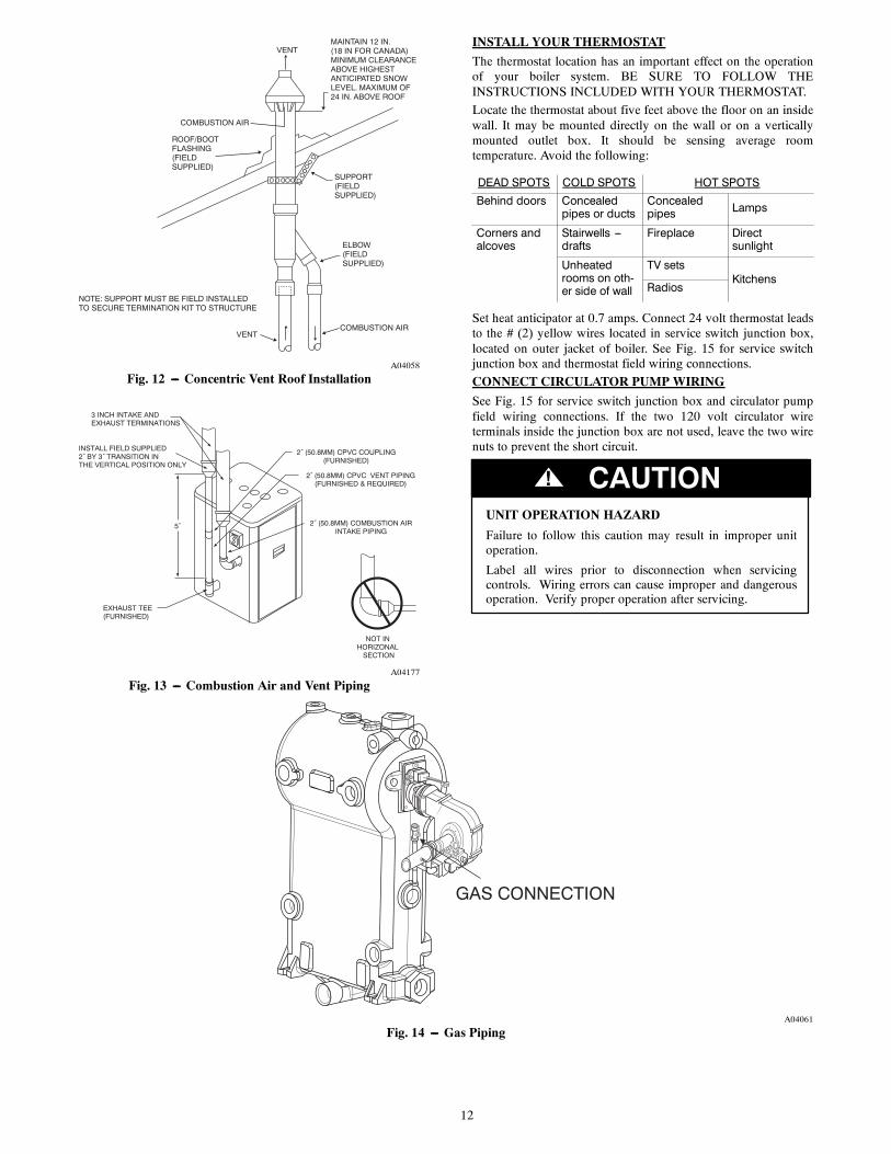
MAINTAIN 12 IN.(18 IN FOR CANADA)MINIMUM CLEARANCEABOVE HIGHEST ANTICIPATED SNOWLEVEL. MAXIMUM OF 24 IN. ABOVE ROOF
ROOF/BOOTFLASHING(FIELDSUPPLIED)
A04058
Fig. 12 --- Concentric Vent Roof Installation
5˝
3 INCH INTAKE ANDEXHAUST TERMINATIONS
EXHAUST TEE(FURNISHED)
2˝ (50.8MM) COMBUSTION AIRINTAKE PIPING
2˝ (50.8MM) CPVC COUPLING(FURNISHED)
2˝ (50.8MM) CPVC VENT PIPING(FURNISHED & REQUIRED)
INSTALL FIELD SUPPLIED2˝ BY 3˝ TRANSITION INTHE VERTICAL POSITION ONLY
NOT IN HORIZONAL
SECTION
A04177
Fig. 13 --- Combustion Air and Vent Piping
INSTALL YOUR THERMOSTAT
The thermostat location has an important effect on the operationof your boiler system. BE SURE TO FOLLOW THEINSTRUCTIONS INCLUDED WITH YOUR THERMOSTAT.
Locate the thermostat about five feet above the floor on an insidewall. It may be mounted directly on the wall or on a verticallymounted outlet box. It should be sensing average roomtemperature. Avoid the following:
DEAD SPOTS COLD SPOTS HOT SPOTSBehind doors Concealed
pipes or ductsConcealedpipes Lamps
Corners andalcoves
Stairwells ---drafts
Fireplace Directsunlight
Unheatedrooms on oth-er side of wall
TV setsKitchens
Radios
Set heat anticipator at 0.7 amps. Connect 24 volt thermostat leadsto the # (2) yellow wires located in service switch junction box,located on outer jacket of boiler. See Fig. 15 for service switchjunction box and thermostat field wiring connections.
CONNECT CIRCULATOR PUMPWIRING
See Fig. 15 for service switch junction box and circulator pumpfield wiring connections. If the two 120 volt circulator wireterminals inside the junction box are not used, leave the two wirenuts to prevent the short circuit.
UNIT OPERATION HAZARD
Failure to follow this caution may result in improper unitoperation.
Label all wires prior to disconnection when servicingcontrols. Wiring errors can cause improper and dangerousoperation. Verify proper operation after servicing.
CAUTION!
GAS CONNECTION
A04061
Fig. 14 --- Gas Piping

13
A06088
Fig. 15 --- Field Wiring Connections
If any of the original wire as supplied wiht this appliance must be replaced, it must be replaced with type 150_C Thermoplastic wire or its equivalentA06089
Fig. 16 --- Schematic Wiring Connections
14
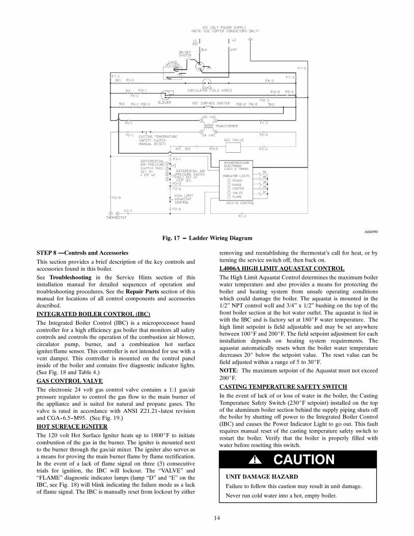
A06090
Fig. 17 --- Ladder Wiring Diagram
STEP 8 —Controls and AccessoriesThis section provides a brief description of the key controls andaccessories found in this boiler.
See Troubleshooting in the Service Hints section of thisinstallation manual for detailed sequences of operation andtroubleshooting procedures. See the Repair Parts section of thismanual for locations of all control components and accessoriesdescribed.
INTEGRATED BOILER CONTROL (IBC)
The Integrated Boiler Control (IBC) is a microprocessor basedcontroller for a high efficiency gas boiler that monitors all safetycontrols and controls the operation of the combustion air blower,circulator pump, burner, and a combination hot surfaceigniter/flame sensor. This controller is not intended for use with avent damper. This controller is mounted on the control panelinside of the boiler and contains five diagnostic indicator lights.(See Fig. 18 and Table 4.)
GAS CONTROL VALVE
The electronic 24 volt gas control valve contains a 1:1 gas/airpressure regulator to control the gas flow to the main burner ofthe appliance and is suited for natural and propane gases. Thevalve is rated in accordance with ANSI Z21.21--latest revisionand CGA--6.5--M95. (See Fig. 19.)
HOT SURFACE IGNITER
The 120 volt Hot Surface Igniter heats up to 1800_F to initiatecombustion of the gas in the burner. The igniter is mounted nextto the burner through the gas/air mixer. The igniter also serves asa means for proving the main burner flame by flame rectification.In the event of a lack of flame signal on three (3) consecutivetrials for ignition, the IBC will lockout. The “VALVE” and“FLAME” diagnostic indicator lamps (lamp “D” and “E” on theIBC, see Fig. 18) will blink indicating the failure mode as a lackof flame signal. The IBC is manually reset from lockout by either
removing and reestablishing the thermostat’s call for heat, or byturning the service switch off, then back on.
L4006A HIGH LIMIT AQUASTAT CONTROL
The High Limit Aquastat Control determines the maximum boilerwater temperature and also provides a means for protecting theboiler and heating system from unsafe operating conditionswhich could damage the boiler. The aquastat is mounted in the1/2” NPT control well and 3/4” x 1/2” bushing on the top of thefront boiler section at the hot water outlet. The aquastat is tied inwith the IBC and is factory set at 180_F water temperature. Thehigh limit setpoint is field adjustable and may be set anywherebetween 100_F and 200_F. The field setpoint adjustment for eachinstallation depends on heating system requirements. Theaquastat automatically resets when the boiler water temperaturedecreases 20_ below the setpoint value. The reset value can befield adjusted within a range of 5 to 30_F.
NOTE: The maximum setpoint of the Aquastat must not exceed200_F.
CASTING TEMPERATURE SAFETY SWITCH
In the event of lack of or loss of water in the boiler, the CastingTemperature Safety Switch (230_F setpoint) installed on the topof the aluminum boiler section behind the supply piping shuts offthe boiler by shutting off power to the Integrated Boiler Control(IBC) and causes the Power Indicator Light to go out. This faultrequires manual reset of the casting temperature safety switch torestart the boiler. Verify that the boiler is properly filled withwater before resetting this switch.
UNIT DAMAGE HAZARD
Failure to follow this caution may result in unit damage.
Never run cold water into a hot, empty boiler.
CAUTION!

15
DIFFERENTIAL PRESSURE AIR PROVING SWITCH (2)
The diaphragm type differential pressure switches are connectedby vinyl tubing to the gas valve and the air inlet connection onthe negative side and the sight glass adapter on the positive side.The pressure switches monitors airflow by sensing the diffentialpressure measured in inches of water (“ w.c.). The factory settingson these switches are 0.5” w.c. on the normally open switch and3.5” w.c. for the normally closed switch. See the Sequence ofOperation section of this manual for details on the operation ofthe differential pressure switches.
BLOWER
The blower provides a means for pushing combustion air into andthrough the mixer, the burner, and the flue ways of the castaluminum boiler section before being discharged through the ventpiping to the outdoors.
CIRCULATOR PUMP
Every forced hot water system requires at least one circulatingpump. The circulating pump imparts the necessary energy tomove the water through the closed loop supply and return pipingsystems, terminal heating equipment (i.e. finned tube radiators,etc.) and back through the boiler for reheating. To provide therequired hot water flow rates, the circulator pump must beproperly sized to overcome frictional losses (usually measured infeet of water, also referred to as “pump head loss”) of the supplyand return piping systems and boiler. The circulator pump isfurnished in a carton within the boiler cabinet. The circulator(s)should always be located in the downstream (i.e., “pumpingaway”) side of the expansion tank.
DRAIN VALVE
The manual drain valve provides a means of draining the water inthe heating system, including the boiler and hot water supply andreturn piping systems installed above the drain valve. This drainvalve is installed in the 3/4” tapping at the bottom of the frontboiler section. Any piping installed below the elevation of thisdrain valve will require additional drain valves to be installed atlow points in the piping systems in order to drain the entiresystem.
ASME RATED PRESSURE RELIEF VALVE
Each boiler must have a properly sized and installed AmericanSociety of Mechanical Engineers rated pressure relief valve.Water expands as it is heated by the burner/boiler sections. Ifthere is no place for the water to expand its volume, (i.e. aproperly sized and properly functioning expansion tank) pressureon the inside of the boiler and heating system will increase. Thefurnished relief valve will automatically open at 30 psig pressureto relieve the strain on the boiler and heating system from theincreasing pressure. The pressure relief valve discharge must bepiped with the same size as the valve discharge opening to anopen drain, tub or sink, or other suitable drainage point notsubject to freezing, in accordance with ASME specifications.Failure to provide the pressure relief valve with piping as hereindescribed may cause water damage and/or serious bodily injury.The boiler manufacturer is not responsible for any water damageor personal injury.
BLOCKED VENT SAFETY SHUTOFF
The boiler is equipped with a blocked vent safety shutoff whichshuts off the main burner gas in the event that the airflow ofcombustion products through the flue--way is reduced. In theevent of a blocked flue--way, enough air will not be available tosupport combustion and the IBC will lock out due to loss ofadequate air flow. Pressure switches monitor air flow by sensingdifferential pressure. The contacts are normally open and closewhen the draft inducer is running and causing the differentialpressure at the switch to exceed its setting. The closed switchproves there is adequate air flow for combustion. The pressureswitch shuts off the main burner if the differential pressure isinadequate due to a blocked vent pipe, a blocked air intake, a
blocked boiler section, or a blocked air inducer. After 5 minutesof inadequate differential pressure, the IBC will lock out. The“Purge” indicator lamp will blink, indicating a failure to proveadequate combustion air flow or flue gas flow. (See Fig. 18.) TheIBC will automatically reset after 15 minutes or can be manuallyreset as noted in the section titled “Hot Surface Igniter.” If theboiler cannot be restored to normal operating condition byresetting the control, contact a qualified service agency to checkthe heat exchanger flue--ways for blockage.
LOWWATER CUT--OFF
This unit is equipped with a Low Water Cut--Off control thatprotects against dry firing. This control provides burner cut--off ifthere is an unsafe water loss, which can result from a broken orleaking radiator or pipe, or a cracked section in the boiler. Awater/glycol mixture up to 50 percent concentration may be usedwith the Low Water Cut--Off.
(OPTIONAL) EXTERNAL CONDENSATE PUMP
For installations where there is no floor drain or other appropriatedrainage receptacle available to receive condensate from theboiler, an external float activated condensate pump with integralsump is required. The condensate pump can be piped to a remotetie in point to a sanitary sewer system. For this application, theboiler must be installed so that proper pitch of piping to theexternal condensate reservoir (sump) can be accomplished. Usewood frame or blocks to raise boiler as required for properinstallation.
START--UP AND CHECK--OUT PROCEDURES
STEP 1 —Water Treatment and Freeze Protection
1. When filling the boiler and heating system, watertreatment is generally not required or desired. Consultlocal water treatment specialist for water treatmentrecommendations if your water pH levels are below 7.0 orhardness is above 7 grains hardness.
a. This boiler is designed for use in a closed hydronicheating system ONLY!
b. Excessive feeding of fresh make--up water to the boilermay lead to premature failure of the boiler sections.
2. Use clean fresh tap water for initial fill and periodicmake--up of boiler.
a. A sand filter must be used if fill and make--up waterfrom a well is to be used.
b. Consideration should be given to cleaning the heatingsystem, particularly in retrofit situations, where a newboiler is being installed in an older piping system.
c. In older systems, obviously discolored, murky, or dirtywater, or a pH reading below 7, are indications that thesystem should be cleaned.
d. A pH reading between 7 and 8 is preferred.
3. Antifreeze, if needed, must be of a type specificallydesigned for use in closed hydronic heating systems andmust be compatible with aluminum and be compatiblewith type 356 T6 aluminum at operating temperaturesbetween 20 and 250 degrees F.
a. Use of antifreeze must be in accordance with localplumbing codes.
b. Pure glycol solutions are very corrosive, thereforehydronic system antifreeze typically contains corrosioninhibitors. Different brands of hydronic systemantifreeze contain different types of corrosioninhibitors. Some brands have corrosion inhibitors thatbreak down more rapidly or become ineffective athigher temperatures when used with aluminum. Thiscould lead to premature failure of the aluminum boiler.Consult the antifreeze manufacturer on thecompatibility of their product with aluminum.

16
Table 4—Diagnostic Sequence
SEQUENCE OF OPERATION DIAGNOSTIC INDICATOR LAMPSA B C D E
Lamp A is illuminated, indicating that the integrated controlis receiving 24 volts and is in standby waiting for thethermostat to call for heat.
X
Thermostat calls for heat, energizing the system circulator. X
Integrated boiler control performs self check of internal cir---cuitry, lasting approximately two seconds, and energizes the X
draft inducer.The draft inducer comes up to speed and establishescombustion airflow, causing the normality open differentialpressure air proving switch contacts to close.When combustion airflow is proved, Lamp B is illuminatedindicating that the 15 second pre---purge cycle has begun.
X X
After the pre---purge has completed, Lamp B is extinguishedand Lamp C is illuminated, indicating power is being deliv---ered to the hot surface igniter for the 20 second igniter warm---up period. The bright yellow---orange glow of the hot
X X
surface igniter can be observed through the observation porton the boiler.
After the igniter warm---up period the integrated boiler con---trol energizes the gas valve, which is indicated by the illumi---nation of Lamp D. Two seconds later Lamp C will extinguish X X Xwhen the integrated boiler control stops sending power to the
hot surface igniter.The integrated boiler control then enters a 6 second trial forignition mode. This is indicated by a low level illumination ofLamp E. During the last 2 seconds of this trial for ignitionmode, main burner flame is proven by flame rectification X X Xthrough the hot surface igniter, providing a flame signal thatis relayed to the integrated boiler control, fully illuminating
Lamp E.The thermostat ends its call for heat, causing the integratedboiler control to de---energize the gas valve and system circu-lator.Lamp D is extinguished while the unit enters the 30 secondpost purge mode, indicated by the illumination of Lamp B.Lamp E will remain illuminated as the remainder of the
X X
gas in the blower is burned off (approximately 2 seconds).During post purge the blower remains powered and clears
out any residual products of combustion.After the post purge mode the draft inducer is de---energized,lamp B is extinquished, and the unit goes into standby mode X
until the next call for heat from the thermostat.NOTE: First attempts at cold starts may be rough due to gas line not being completely purged of air causing low firing rate and high excess air levels.

17
c. Follow the antifreeze manufacturer’s instructions ondetermining proper ratio of antifreeze to water for theexpected low temperature conditions, and formaintaining the quality of the antifreeze solution fromyear to year. Improperly maintained antifreezesolutions will gradually lose their ability to protect thealuminum boiler from corrosion.
d. The recommended premixed antifreeze solution isINTERCOOL NFP--50. This product is sold direct toinstalling contractors by the antifreeze manufacturer.Please contact Interstate Chemical Company, NewYork Customer Service at 1--800--422--2436 topurchase. Use of an alternate manufacturer’s premixantifreeze is acceptable if the product specifications arecompatible with those of the recommended premixantifreeze and the antifreeze is compatible with type356 T6 aluminum. Use of incompatible antifreezecould damage the heat exchanger and could voidproduct warranty.The antifreeze must be maintained per thespecifications of the manufacturer. Failure to do socould result in the warranty being voided. Follow theantifreeze manufacturer’s instructions on determiningthe proper ratio of antifreeze to water for the expectedlow temperature conditions and for maintaining theantifreeze solution from year to year.
e. DO NOT USE AUTOMOTIVE ANTIFREEZE, asthe type of corrosion inhibitors used will coat theboiler’s heat transfer surfaces and greatly reducecapacity and efficiency.
f. Use of antifreeze in any boiler will reduce heatingcapacity by as much as 10--20 percent, due to differingheat transfer and pumping characteristics. This must betaken into consideration when sizing the heatingsystem, pump(s) and expansion tank. Consultantifreeze manufacturer’s literature for specificinformation on reduced capacity.
g. Water content of the boiler is 2.6 gallons (10 liters).
STEP 2 —Filling Boiler with Water and Purging Air forSystems with Diaphragm Type Expansion Tanks
Refer to appropriate “Near Boiler Piping” diagrams.
1. Close all zone service valves on the supply and returnpiping. Open the feed valve and fill boiler with water.
Make sure air vent is open. Hold relief valve open untilwater runs air free for five seconds to rapidly bleed airfrom boiler, then let the relief valve snap shut.
2. Open the zone service valve on the supply pipe for thefirst zone. Open the purge valve on the first zone. Feedwater will fill the zone, pushing air out the purge valve.Close the purge valve when the water runs air free. Closethe zone service valve.
3. Repeat step 2 for all remaining zones.
4. Open all service valves. Any air remaining trapped in thereturn lines between the service valves and the boiler willbe pushed towards the air vent when the boiler is placed inoperation.
5. Inspect piping system. Repair any leaks immediately.
STEP 3 —Filling Boiler with Water and Purging Air forSystems with Conventional Closed Type Expansion Tanks
Refer to appropriate “NEAR BOILING PIPING” diagrams.
1. Close all zone service valves on the supply and returnpiping and close the expansion tank service valve. Drainexpansion tank. Open the feed valve and fill boiler withwater. Hold relief valve open until water runs air free forfive seconds to rapidly bleed air from boiler, then let therelief valve snap shut.
2. Open the zone service valve on the supply pipe for thefirst zone. Open the purge valve on the first zone. Feedwater will fill the zone, pushing air out the purge valve.Close the purge valve when the water runs air free. Closethe zone service valve.
3. Repeat step 2 for all remaining zones.
4. Open the expansion tank service valve and the tank vent.Fill the tank to the proper level and close the tank vent.Remove the handle from the expansion tank service valveso the homeowner doesn’t accidentally close it.
5. Open all service valves. Any air remaining trapped in thereturn lines between the service valves and the boiler willbe pushed towards the expansion tank when the boiler isplaced in operation.
6. Inspect piping system. Repair any leaks immediately.
NOTE: DO NOT use stop leak compounds. Leaks in threadedconnections in the aluminum boiler sections must be repairedimmediately. Aluminum threads will not seal themselves.
DIAGNOSTIC INDICATOR LAMPS
POWER
PURGE
IGNITER
VALVE
FLAME
A
B
C
D
E
UT-1013 INTEGRATED BOILER CONTROL
40 VA TRANSFORMER CONTROL
CONTROL PANEL
A04062
Fig. 18 --- Indicator Lights

18
STEP 4 —Placing Boiler in OperationREAD BEFORE OPERATING APPLIANCE
1. This appliance does not have a pilot. It is equipped with anignition device which automatically lights the burner. DoNOT try to light this burner by hand.
2. Before operating, smell all around the appliance area forgas. Be sure to smell next to the floor because some gas isheavier than air and will settle to the floor.
WHAT TO DO IF YOU SMELL GAS
Do not try to light any appliance.
Do not touch any electric switch or use any phone in the building.
Immediately call your gas supplier from a neighbor’s phone.Follow the gas supplier’s instructions.
If you cannot contact your gas supplier, call the fire department.
3. Use only your hand to turn the gas ball valve. Never usetools. If the valve will not turn by hand, do not try torepair it, call a qualified service technician. Force orattempted repair may cause fire or explosion.
4. Do not use this appliance if any part has been under water.Immediately call a qualified service technician to inspectthe appliance and to replace any part of the control systemand any gas control which has been under water.
OPERATING INSTRUCTIONS
1. STOP! Read the safety information above beforeoperating this appliance.
2. Set the thermostat to the lowest setting.
3. Turn off all electrical power to the appliance.
4. This appliance does not have a pilot. It is equipped with anignition device which automatically lights the burner. DoNOT try to light this burner by hand.
5. Remove the front jacket panel.
6. Turn off the gas ball valve. Valve handle should beperpendicular to the gas pipe.
7. Wait five minutes for any gas to clear. Then smell for gas,including near the floor. If you smell gas STOP! Followinstructions under “WHAT TO DO IF YOU SMELLGAS” above. If you do not smell gas, go to next step.
8. Turn the gas ball valve to the “on” position. The handle onthe valve should be parallel to the gas pipe.
9. Replace the front jacket panel.
10. Turn on all electrical power to the appliance.
11. Set thermostat to desired setting.
12. If the appliance will not operate, follow the instructions“TO TURN OFF GAS TO APPLIANCE” and call yourservice technician or gas supplier.
IF BURNER APPEARS TO PULSATE DURING IGNITION
1. Turn off boiler power and shut off gas supply to the boiler.
2. Take the burner assembly apart by removing thecombustion air blower and gas valve/venturi assemblyfrom the boiler and visually inspect the inside of theburner. Look for any debris (PVC shavings, etc.) and ifanything is present, remove it.
3. Reassemble burner assembly, turn gas supply and boilerpower back on, and relight boiler.
IF BURNER STILL PULSATES OR FAILS TO LIGHT
1. Check for proper vent and intake pipe sizing and forproper vent lengths and vent configuration by referring toStep 2, “Before Installing the Boiler,” and Step 5,“Combustion Air and Vent Pipe,” located in theINSTALLATION section in this manual.
2. Check for proper gas supply pressure and proper gas linesizing to the boiler by referring to Step 6, “Gas Supply
Piping,” located in the INSTALLATION section in thismanual.
3. Check for orifice in negative pressure hose at gas valveand 2” air intake pipe upstream of gas valve.
4. Relight boiler.
5. If boiler still does not light, the air inlet pipe may need tobe disconnected to allow the boiler to start in order toverify the boiler firing rate and combustion properties.The inlet air pipe can be disconnected by removing thePVC inlet air piping from the Femco fitting located on theair inlet of the gas valve/venturi assembly. Relight boiler.
6. When the boiler lights, the firing rate and combustionshould be checked per the “Adjustments and Checkout”procedure in Step 5 of the START--UP ANDCHECK--OUT PROCEDURES section of this manual. Ifthe air inlet piping was disconnected in step 4 (above),leave it disconnected and make the first adjustment.Reconnect air inlet piping, recheck combustion CO2, andadjust again if necessary.
7. If burner pulsation continues or boiler fails to light afterperforming the above procedures, please contact TechnicalService at 1--800--325--5479 for further assistance.
TO TURN OFF GAS TO APPLIANCE
1. Set the thermostat to the lowest setting.
2. Turn off all electric power to the appliance if service is tobe performed.
3. Remove the front jacket panel.
4. Turn gas ball valve off. The handle should beperpendicular to the gas pipe.
5. Replace the front jacket panel.
Safe lighting and other performance criteria were met with the gasmanifold and control assembly provided on the boiler when theboiler underwent tests specified in ANSI Z21.13-- latest revision.
STEP 5 —Check Out Procedure and AdjustmentsVERIFY PROPER SEQUENCE OF OPERATION
The sequence can be followed via the diagnostic indicator lampson the integrated boiler control in Fig. 18. This is the normalsequence of operation. (See Table 4.) A more detailed sequenceof operation containing potential faults can be found in theservice hints section.
INSPECT VENTING AND AIR INTAKE SYSTEM
Operate the boiler and verify that all vent/air intake connectionsare gastight and watertight. Repair any leaks immediately.
INSPECT CONDENSATE DRAIN
Verify that all connections are watertight, and that condensateflows freely. Repair any leaks immediately.
INSPECT SYSTEM PIPING
Verify that all connections are watertight. Repair any leaksimmediately.
TEST IGNITION SYSTEM SAFETY SHUTOFF DEVICE
1. Turn off manual gas ball valve.
2. Set thermostat to call for heat.
3. Boiler begins normal sequence of operation.
4. After approximately 30 seconds (prepurge and igniterwarm--up period), lamp D illuminates, indicating gas valveis powered.
5. After 4 seconds, gas valve closes, lamp D goes out asintegrated boiler control senses that flame is not present.
6. To restart system, follow operating instructions under“Step 4--Placing Boiler in Operation.”

19
Table 5—Natural Gas
NOMINAL INPUT 200,000 175,000 150,000 125,000
AltitudeVent Lengths Vent Lengths Vent Lengths Vent Lengths
Min Max Min Max Min Max Min Max
0 200,000 200,000 175,000 175,000 150,000 150,000 125,000 125,000
1,000 197,000 196,500 172,400 172,200 147,800 147,400 123,500 123,000
2,000 194,000 193,000 169,800 169,400 145,600 144,800 122,000 121,000
3,000 191,000 189,500 167,200 166,600 143,400 142,200 120,500 119,000
4,000 188,000 186,000 164,600 163,800 141,200 139,600 119,000 117,000
5,000 185,000 182,500 162,000 161,000 139,000 137,000 117,500 115,000
6,000 182,000 179,000 159,400 158,200 136,800 134,400 116,000 113,000
7,000 179,000 175,500 156,800 155,400 134,600 131,800 114,500 111,000
8,000 176,000 172,000 154,200 152,600 132,400 129,200 113,000 109,000
9,000 173,000 168,500 151,600 149,800 130,200 126,600 111,500 107,000
10,000 170,000 165,000 149,000 147,000 128,000 124,000 110,000 105,000
Table 6—LP Gas
NOMINAL INPUT 200,000 175,000 150,000 125,000
AltitudeVent Lengths Vent Lengths Vent Lengths Vent Lengths
Min Max Min Max Min Max Min Max
0 200,000 200,000 175,000 175,000 150,000 150,000 125,000 125,000
1,000 195,900 195,750 171,900 171,200 146,900 146,700 123,050 122,250
2,000 191,800 191,500 168,800 167,400 143,800 143,400 121,100 119,500
3,000 187,700 187,250 165,700 163,600 140,700 140,100 119,150 116,750
4,000 183,600 183,000 162,600 159,800 137,600 136,800 117,200 114,000
5,000 179,500 178,750 159,500 156,000 134,500 133,500 115,250 111,250
6,000 175,400 174,500 156,400 152,200 131,400 130,200 113,300 108,500
7,000 171,300 170,250 153,300 148,400 128,300 126,900 111,350 105,750
8,000 167,200 166,000 150,200 144,600 125,200 123,600 109,400 103,000
9,000 163,100 161,750 147,100 140,800 122,100 120,300 107,450 100,250
10,000 159,000 157,500 144,000 137,000 119,000 117,000 105,500 97,500NOTE: The boiler automatically derates input as altitude increases. No alterations to boiler are required for altitudes above sea level.These low pressure gas---fired hot water boilers are design certified by CSA International, for use with natural and propane gases. The boilers are constructedand hydrostatically tested for a maximum working pressure of 50 psig (pounds per square inch gauge) in accordance with A.S.M.E. (American Society ofMechanical Engineers) Boiler and Pressure Vessel Code Section IV Standards for heating boilers.
TEST HIGH LIMIT CONTROL AND ADJUST
While burner is operating, Adjust setting on high limit controlbelow actual boiler water temperature. Burner should go off whilecirculator continues to operate. Raise limit setting above boilerwater temperature and burner should reignite after pre purge andigniter warm--up period. Set the high limit control to the designtemperature requirements of the system. Maximum high limitsetting is 200_F. Minimum high limit setting is 100_F. Returnhigh limit differential to original setting of 20_F.
TEST OTHER SAFETY CONTROLS
If the boiler is equipped with a low water cut off, a manual resethigh limit, or additional safety controls, test for operation asoutlined by the control manufacturer. Burner should be operatingand should go off when controls are tested. When safety controlsare restored, burner should reignite.
SET THERMOSTAT HEAT ANTICIPATOR (IF USED)AND VERIFY THERMOSTAT OPERATION
For a single thermostat connected to the yellow thermostat leadwires in the furnished field wiring junction box, the heatanticipator should be set at 0.7 amps. For other wiringconfigurations, refer to the instructions provided by thethermostat manufacturer regarding adjustment of heat anticipator.Cycle boiler with thermostat. Raise the thermostat to the highestsetting and verify boiler goes through normal start up cycle.Lower thermostat to lowest setting and verify boiler goes off.
MEASURE THE NATURAL GAS INPUT RATE
Correct input rate is essential for proper and efficient operation ofthe burner and boiler.
1. Determine elevation at installation site.
2. See Table 5 and 6 to determine the correct approximateinput rate for the local elevation.
3. Obtain the yearly average heating value of the local gassupply from the gas utility. At sea level elevation, it shouldbe approximately 1000 Btu’s per standard cubic foot.
4. Operate boiler for 5 minutes.
5. Turn off all other gas appliances, extinguishing standingpilots where applicable.
6. At gas meter, measure time in seconds required to use onecubic foot of gas.
7. Calculate “input rate” according to the following formula:
Btuh input rate = 3600 x heating value from step 3
time from step 6
8. The measured input rate should be within +/--2 percent ofthe input rating from step 2. If not, see theADJUSTMENTS section.

20
ADJUSTMENTS AND CHECKOUT
NOTE: It is important that this appliance operate between 8.5and 10% CO2. To verify that the appliance is operating in thisrange, follow the steps below:
1. Check incoming gas pressure to the appliance using awater column manometer with resolution of 0.1 inch w.c.or better and a range of 0 to 14 inches of w.c. Connect thepositive side of the manometer to the inlet pressure tap onthe gas valve by loosening the inlet pressure tap screwfrom the raised port on the gas valve and sliding themanometer hose over the port. (See Fig. 19.)
2. Drill a hole in the plastic CPVC vent pipe or exhaust tee,just large enough to allow access for the sample probe ofyour combustion analyzer.
3. Turn the thermostat to the closed position so the applianceis activated.
4. Allow the appliance to run for approximately 5 minutes.
5. Insert the sample probe of your combustion analyzer intothe hole you drilled in step 2, about halfway into theexhaust gas stream. Take a flue gas reading and observethe CO2 value. Adjust the throttle screw until the CO2value is between 8.5 and 10%. Turning the throttle screwclockwise decreases the rate and the CO2 value. Turningthe throttle screw (See Fig. 19) counterclockwise increasesthe rate and the CO2 value. Allow the appliance tostabilize for approximately 1 minute after adjusting thethrottle screw before you take a reading with yourcombustion analyzer.
6. After adjustments are made, turn the gas and electricsupplies to the boiler off. Remove the manometer hosefrom the gas valve and tighten the screw on the inletpressure tap. Remove the CO meter and plug the hole inthe CPVC with 400_F high temperature silicone.
7. Return the thermostat switch to its original position.
INLETPRESSURE TAP
THROTTLE ADJUSTMENT SCREWTurn clockwise to decrease rate and CO2
Counterclockwise to increase rate and CO2
VENTURI VALVE
INLET
MOLEXPIN
HEADER
OUTLET
A06100
Fig. 19 --- Gas Valve
Final Checkout of the Installation
After any adjustment to the appliance, observe several completecycles to ensure that all components function correctly.
SET THERMOSTAT TO DESIRED ROOMTEMPERATURE
Observe several operating cycles to verify proper operation.
REVIEW ALL INSTRUCTIONS
Review all instructions shipped with this boiler with owner ormaintenance person. Instructions must be affixed on or adjacentto the boiler.
COMPLETE AND SIGN THE INSTALLATION ANDCHECK--OUT CERTIFICATE AT THE END OF THISMANUAL.
CARE AND MAINTENANCE
Maintenance as outlined below can be performed by theowner unless otherwise noted.The acidic nature of flue gases condensing on the aluminumboiler sections will cause the formation of aluminum oxide. Thisoxide formation is normal, is generally uniform throughout theboiler sections, and represents a negligible mass of aluminum thatis consumed by oxidation during the life of the boiler. If leftunchecked, this buildup may eventually cause blockage of theflue gas passages in the boiler sections, reducing efficiency, andultimately shutting down the boiler due to lack of combustion airflow. Regular service and maintenance by a qualified serviceagency must be performed to assure safe trouble free operationand maximum efficiency. It is recommended to service theappliance at least once every 12 months.
STEP 1 —Beginning of Each Heating Season1. Schedule an annual service call by a qualified serviceagency, which includes:
a. Examine flue passages between boiler sections, burner,and condensate lines, and clean, if necessary, followingthe annual examination and cleaning instructions listedin Procedure 6.
b. Visually inspect venting and air intake system forproper operation. If the vent or air intake show anysigns of deterioration or leakage, repair or replace themimmediately. Insure proper reassembly and resealing ofthe vent and air intake system.
c. Check for and remove any obstruction to the flow ofcombustion air or venting of flue gases.
d. Follow instructions for “PLACING BOILER INOPERATION.”
e. Follow instructions for “CHECK OUT PROCEDUREAND ADJUSTMENTS.”
f. Visually inspect condensate drain line for properoperation. Check for deteriorated or pluggedcondensate drain line.
g. Check all gasketed joints for leakage, and tighten boltsor replace gaskets, if necessary.
h. Remove jacket front and top panels and check forpiping leaks around relief valve and other fittings.Repair, if found. DO NOT use stop leak compounds.
2. Check that boiler area is free from combustible materials,gasoline, and other flammable vapors and liquids.
3. Circulator pump and blower motor furnished with boilerare permanently lubricated from the factory and require nofurther lubrication. Additional or non--factory suppliedpumps and/or motors should be lubricated according tothe pump and/or motor manufacturer’s instruction.
STEP 2 —Daily During Heating Season1. Check for and remove any obstruction to the flow ofcombustion air or venting of flue gases.
2. Check that boiler area is free from combustible materials,gasoline, and other flammable vapors and liquids.
STEP 3 —Monthly During Heating Season
1. Remove jacket front and top panels and check for pipingleaks around relief valve and other fittings. If found,contact a qualified service agency to repair. DO NOT usestop leak compounds.
2. Test relief valve. Refer to valve manufacturer’sinstructions packaged with relief valve.
3. Visually inspect venting and air intake system for properfunction. If the vent or air intake show any signs ofdeterioration or leakage, contact a qualified service agencyto repair or replace them immediately and to insure properreassembly and resealing of the vent and air intake system.

21
4. Visually inspect the PVC condensate drain pipe for properoperation. If the drain pipe shows any signs of blockage,leakage, or deterioration contact a qualified service agencyto clean, repair, or replace it immediately.
5. Check air vent(s) for leakage.
STEP 4 —Periodically During Heating SeasonWhere low water cut offs are used, a periodic inspection of thelow water cut off is necessary, including flushing of float typedevices. Refer to low water cut off manufacturer’s specificinstructions.
STEP 5 —End of Heating Season--Annual ShutdownProcedure
1. Follow instructions “TO TURN OFF GAS TOAPPLIANCE.”
2. If heating system is to remain out of service duringfreezing weather, and does not contain antifreeze, drainsystem completely. If boiler will be exposed to freezingtemperatures, drain condensate lines. Otherwise, do notdrain system or boiler.
STEP 6 —Annual Examination and Cleaning of BoilerComponents
The following service procedures must be performed only by aqualified service agency. Boiler owner should not attempt theseprocedures.
1. Before Servicing, turn off electrical power to boiler atservice switch. Close manual gas valve to turn off gassupply to boiler.
2. Flue passages are examined by removing the blowerassembly from the casting. Refer to the repair partsdiagram for the boiler block and piping assembly at theend of this manual. The procedure for examining andcleaning the burner is described below.Any buildup of sediment or aluminum oxide (whitepowdery or flaky substance) in the flue passages must becleaned as follows:
a. Remove jacket front and top panels.
b. Confirm that manual gas valve is closed anddisconnect gas line to gas valve at union.
c. Disconnect wires to gas valve and igniter.
d. Remove air inlet assembly from gas valve.
e. Loosen but do not remove five (5) nuts attachingblower adapter assembly to boiler.
f. Remove two (2) igniter screws and very carefullyremove the igniter. Use care when removing theigniter, it is very brittle! Do not touch the igniterelement with your fingers or hands as oil or debris willcause premature failure to the igniter.
g. Remove five (5) nuts and remove blower adapterassembly. Remove burner and gaskets.
h. Aluminum oxide deposits are water soluble and maybe rinsed away with spraying or running water.
i. Use a flexible handle nylon brush to loosen sedimentand aluminum oxide on all heating surfaces of boiler.Refer to the repair parts diagrams. Be sure that youdo not get brush stuck in heat exhanger!
j. After brushing and rinsing, remove any remainingloosened sediment using a shop vacuum with a snorkelattachment.
k. Inspect burner for any foreign matter in the flame portsor inside the burner. Any foreign matter should beremoved by blowing with compressed air orvacuuming.
l. Reinstall burner and gaskets and position bloweradapter assembly over studs. Install five (5) nuts butdo not tighten. Reinstall igniter and igniter gasket and
fasten with two (2) screws. Use care when installingthe igniter. It is very brittle! Do not touch the igniterelement with your fingers or hands as oil or debris willcause premature failure to the igniter. Tighten five (5)nuts holding blower adapter assembly.
m. Connect:
(1.) gas line to gas valve
(2.) air inlet assembly to gas valve using 2” x 1--1/2”flexible coupling
(3.) pressure switch hose to gas valve and air inletassembly
(4.) 2 inch flexible coupling to boiler exhaust port
(5.) igniter wires
(6.) gas valve wires
3. Visually inspect the condensate trap. Refer to repair partsdiagrams. Any foreign material or debris that is visible inthe condensate lines needs to be cleaned out as describedbelow.
a. Remove 1/2” PVC cap from 1/2” PVC tee.
b. Inspect for sediment or blockage.
c. Flush out with water or vacuum.
d. Follow the instructions under “NEAR BOILERPIPING” for filling condensate trap with water.
e. Replace 1/2” PVC cap.
4. Inspection of the flue connector requires the followingsteps (Refer to the repair parts diagram.)
a. Loosen the clamp on the draft inducer end of the 2inch flexible coupling that connects the vent tee to theexhaust port.
b. Inspect interior of vent tee. Any buildup of sedimenton the inside surface must be cleaned.
c. Reconnect the 2 inch flexible coupling to the draftinducer outlet.
STEP 7 —Differential Air Pressure Switch CheckThe following steps and diagram indicate the locations of theconnection points required to check the differential air pressure.
The differential air pressure switch is a safety device which willprevent the boiler from firing if there is an air intake, boiler heatexchanger or vent blockage.
Turn off service switch, or lower thermostat setting.
Remove vinyl caps from tee. Install testing lines as shown toinclined manometer or differential pressure gauge with the abilityto read 0.01” to 5.0” w.c.
Turn on service switch and set thermostat to call for heat. (SeeFig. 20.)
If manometer readings do not correspond to the chart above,check for possible causes:
S Blockage or moisture in suction lines to switch.
S Blockage in air intake or vent pipes.
S Undersized air intake or vent pipes.
S Loose blower wheel on motor shaft.
S Incorrect pressure switch or pressure switch setpoint
When pressure reading is proper and the pressure switch isoperating properly, remove testing lines and reinstall vinyl caps toTee and 3--way connector.
SERVICE HINTS AND TROUBLESHOOTING
See Fig. 21--32.

22
BOILER STATUS DIFFERENTIAL PRESSURE SWITCH CONTACTS
Not Running 0”Closed at 3.5”Closed at 0.5”
Running without Blockage (Approximate)
1.00” For Model--125 Closed at 3.5”1.50” For Model--150 Closed at 0.5”1.50” For Model--175
2.00” For Model--200
Running with Blockage Less Than or Equal to SetpointsOpen at 3.5”Closed at 0.5”
3
2
12"
13"
15 1/2"
SIGHT GLASS& ADAPTER
413 1/4"
7
4 6"4 16 1/2"
GAS VALVE
8
6
4
1 4"
4 4"
5
9
9
AIR INLETCONNECTION
2 @ 2" EA.
A06107
Fig. 20 --- Differential Air Pressure

23
2 SEC INTO THE 5 SEC IGNITION TRIAL, POWERIS TURNED OFF TO THE HOT SURFACE IGNITER.IGNITER LIGHT OFF.
GAS VALVE OPENS FOR 5 SEC TRIAL FORIGNITION, BLUE ORANGE GLOW OF THE BURNER
CAN BE SEEN THRU OBSERVATION PORT.
GAS VALVE ENERGIZED THRU 3K1 AND 4K1.CONTACTS. VALVE LIGHT ON.
PURGE LIGHT GOES OUT. HOT SURFACE IGNITERPOWERED THRU 5K1 AND 5K2 CONTACTS FOR 20SEC IGNITER WARMUP. BRIGHT YELLOWORANGE GLOW OF THE HOT SURFACE IGNITERCAN BE OBSERVED THRU THE OBSERVATIONPORT IN FRONT OF BOILER SECTION JUSTABOVE IGNITER. IGNITER LIGHT ON.
DETAILED SEQUENCE OF OPERATION
CONTROL LOCKOUT. PURGE LIGHT BLINKS.MANUAL RESET REQUIRED OR CONTROLWILL AUTOMATICALLY RESET AFTER 15MINUTES. CIRCULATOR REMAINS ENERGIZEDAS LONG AS THERE IS A CALL FOR HEAT
OPEN
IBCWAITS FOR
UP TO 5 MINUTESFOR AIR PRESSURESWITCH CONTACTS
TO CLOSEINDICATING FAN
SUCTION PRESENT
CLOSED
CLOSED
OPEN
OPEN
CLOSED YES
NO
IBCCHECKSN.O. AIR
PRESSURESWITCH
IBC SELF CHECK OFINTERNAL CIRCUITRY
1-2 SEC
CIRCULATORENERGIZES THRU
2K1 CONTACTS
THERMOSTATCALLS FOR HEAT
PO WER ONSTANDBY
NORMAL SEQUENCE OF OPERATION
IF MAIN BURNER DOES NOT PROVE FLAME IN 3TRIALS, CONTROL LOCKOUT. VALVE/FLAME LIGHT BLINKS. RESET IS REQUIRED. THISPROBLEM IS A RESULT OF NOT ESTABLISHINGFLAME SIGNAL.
CONTROL WILL ATTEMPT 2 ADDITIONALIGNITION SEQUENCES STARTING WITHPREPURGE
CONTACTS
FALSE POSITIVEPROOF OFAIRFLOW. IBC WAITSFOR 45 SEC FORAIR PRESSURESWITCHCONTACTS TOOPEN
NORMALOPERATION
DOES MAINBURNERPROVE FLAMEWITHIN INITIALFOR IGNITIONPERIOD
DRAFT INDUCERENERGIZES THRU1K1 CONTACTS
PURGE LIGHT ON. AIRFLOW APPROVED.DRAFT INDUCER RUNS FOR 15 SEC PREPURGE
DURING THE LAST 2 SEC OF THE 5 SEC IGNITIONTRIAL, MAIN BURNER FLAME IS PROVED BY FLAMERECTIFICATION THRU HOT SURFACE IGNITER,PROVIDING A FLAME SIGNAL TO IBC. GAS VALVEREMAINS ENERGIZED. BOILER RUNS.
A06101
Fig. 21 --- Normal Sequence of Operation
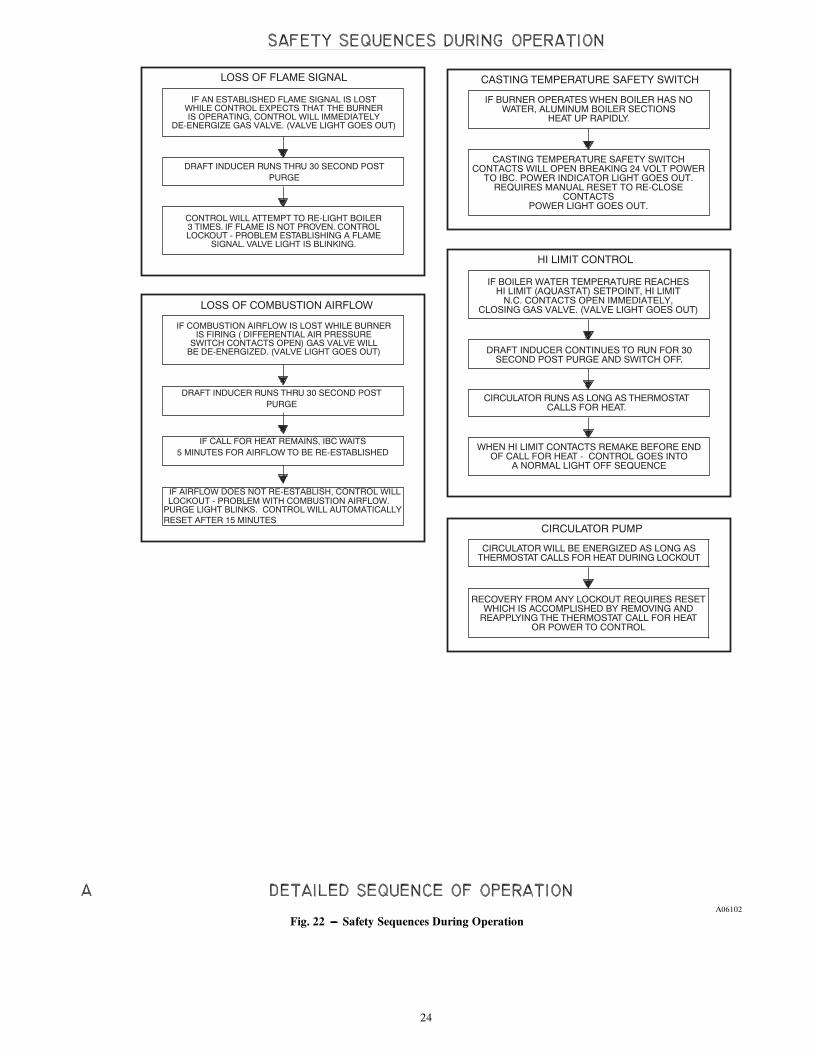
24
CASTING TEMPERATURE SAFETY SWITCHCONTACTS WILL OPEN BREAKING 24 VOLT POWER
TO IBC. POWER INDICATOR LIGHT GOES OUT.REQUIRES MANUAL RESET TO RE-CLOSE
CONTACTSPOWER LIGHT GOES OUT.
IF BOILER WATER TEMPERATURE REACHESHI LIMIT (AQUASTAT) SETPOINT, HI LIMIT
N.C. CONTACTS OPEN IMMEDIATELY,CLOSING GAS VALVE. (VALVE LIGHT GOES OUT)
IF AN ESTABLISHED FLAME SIGNAL IS LOSTWHILE CONTROL EXPECTS THAT THE BURNERIS OPERATING, CONTROL WILL IMMEDIATELY
DE-ENERGIZE GAS VALVE. (VALVE LIGHT GOES OUT)
IF COMBUSTION AIRFLOW IS LOST WHILE BURNERIS FIRING ( DIFFERENTIAL AIR PRESSURE
SWITCH CONTACTS OPEN) GAS VALVE WILLBE DE-ENERGIZED. (VALVE LIGHT GOES OUT)
IF AIRFLOW DOES NOT RE-ESTABLISH, CONTROL WILLLOCKOUT - PROBLEM WITH COMBUSTION AIRFLOW.
PURGE LIGHT BLINKS. CONTROL WILL AUTOMATICALLYRESET AFTER 15 MINUTES
LOSS OF FLAME SIGNAL
DRAFT INDUCER RUNS THRU 30 SECOND POSTPURGE
LOSS OF COMBUSTION AIRFLOW
CONTROL WILL ATTEMPT TO RE-LIGHT BOILER3 TIMES. IF FLAME IS NOT PROVEN. CONTROLLOCKOUT - PROBLEM ESTABLISHING A FLAME
SIGNAL. VALVE LIGHT IS BLINKING.
DRAFT INDUCER RUNS THRU 30 SECOND POSTPURGE
IF CALL FOR HEAT REMAINS, IBC WAITS5 MINUTES FOR AIRFLOW TO BE RE-ESTABLISHED
HI LIMIT CONTROL
DRAFT INDUCER CONTINUES TO RUN FOR 30SECOND POST PURGE AND SWITCH OFF.
CIRCULATOR RUNS AS LONG AS THERMOSTATCALLS FOR HEAT.
WHEN HI LIMIT CONTACTS REMAKE BEFORE ENDOF CALL FOR HEAT - CONTROL GOES INTO
A NORMAL LIGHT OFF SEQUENCE
CIRCULATOR PUMP
CIRCULATOR WILL BE ENERGIZED AS LONG ASTHERMOSTAT CALLS FOR HEAT DURING LOCKOUT
RECOVERY FROM ANY LOCKOUT REQUIRES RESETWHICH IS ACCOMPLISHED BY REMOVING AND
REAPPLYING THE THERMOSTAT CALL FOR HEATOR POWER TO CONTROL
IF BURNER OPERATES WHEN BOILER HAS NOWATER, ALUMINUM BOILER SECTIONS
HEAT UP RAPIDLY.
CASTING TEMPERATURE SAFETY SWITCH
A06102
Fig. 22 --- Safety Sequences During Operation
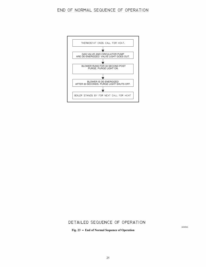
25
GAS VALVE AND CIRCULATOR PUMPARE DE-ENERGIZED. VALVE LIGHT GOES OUT.
BLOWER RUNS FOR 30 SECOND POSTPURGE. PURGE LIGHT ON.
BLOWER IS DE-ENERGIZEDAFTER 30 SECONDS. PURGE LIGHT SHUTS OFF.
A04066
Fig. 23 --- End of Normal Sequence of Operation

26
FIRE, EXPLOSION OR SHOCK HAZARD
Failure to follow this warning could result in personalinjury, death or property damage.
Do not attempt to modify the physical or electricalcharacteristics of this boiler in any way.
! WARNING
IMPORTANT
1. IN A RESET FROM LOCKOUT CONDITION, ALL ELECTRICAL METER READINGS AT THE GASCONTROL VALVE (24 VAC) MUST BE TAKEN WITHIN THE TRIAL FOR IGNITION PERIOD.
2. IF ANY COMPONENT DOES NOT FUNCTION PROPERLY, MAKE SURE IT IS CORRECTLY INSTALLEDAND WIRED BEFORE REPLACING IT.
3. STATIC ELECTRICITY DISCHARGE CAN DAMAGE THE INTEGRATED BOILER CONTROL (IBC).TOUCH METAL SURFACE TO DISCHARGE STATIC ELECTRICITY BEFORE TOUCHING IBC.
4. THE IBC CANNOT BE REPAIRED. IF IT MALFUNCTIONS IT MUST BE REPLACED.
5. ONLY TRAINED, EXPERIENCED SERVICE TECHNICIANS SHOULD SERVICE THE IBC SYSTEMS.FOLLOWING TROUBLESHOOTING, CHECK OUT THE SYSTEM FOLLOWING THE SEQUENCE OFOPERATION SECTION OF THIS CHAPTER FOR A NORMAL LIGHT OFF SEQUENCE.
6. ALL CONTROLS ARE FACTORY TESTED IN THE ASSEMBLY PROCESS AND A DEFECTIVE CONTROLIS GENERALLY THE LEAST LIKELY CAUSE. IF YOU SUSPECT YOU HAVE A DEFECTIVE CONTROL,READ THROUGH THE TROUBLESHOOTING CHART BEFORE YOU REPLACE IT.
7. IT IS EXTREMELY UNLIKELY THAT THE TWO CONSECUTIVE CONTROLS ARE DEFECTIVE. IF ITSEEMS TO BE HAPPENING, CHANCES ARE THAT EITHER THERE IS NOTHING WRONG WITH THECONTROL OR IT IS BEING DAMAGED BY SOME OTHER PROBLEM (AN ELECTRICAL SHORTBURNING OUT A TRANSFORMER, FOR EXAMPLE).
INITIAL SERVICE CHECKS1. BEFORE TROUBLESHOOTING:
A. MAKE SURE THAT CIRCUIT BREAKER IS ON OR FUSE IS OK AT ELECTRICAL PANEL.B. MAKE SURE THAT SERVICE SWITCH IS ON.C. MAKE SURE THAT GAS IS ON AT THE GAS METER, AT ALL APPROPRIATE MANUAL
SHUTOFF VALVES AND AT THE GAS CONTROL VALVE.D. MAKE SURE THAT THE THERMOSTAT IS CALLING FOR HEAT.E. CHECK THAT WIRE CONNECTORS AT THE INTEGRATED BOILER CONTROL AND AT THE
ORIGINATING CONTROL ARE SECURELY PLUGGED IN OR CONNECTED.F. CHECK THAT HOSES ARE SECURELY CONNECTED AND ARE NOT PLUGGED IN OR
DAMAGED.
2. TROUBLESHOOTING TOOLS:A. VOLTMETER TO CHECK 120 VAC AND 24 VACB. CONTINUITY TESTER.C. INCLINED MANOMETER OR PRESSURE GAUGE WITH 0-5.0 RANGE (0.01 SCALE) FOR
MEASURING SUCTION PRESSURES AT PRESSURE SWITCH.D. U-TUBE MANOMETER OR DIFFERENTIAL PRESSURE GAUGE WITH 0-14 RANGE (0.1
SCALE) FOR MEASURING INLET AND MANIFOLD GAS PRESSURES.
3. WHAT IS SYSTEM STATUS? A. CONSULT THE CHART ON THE FOLLOWING PAGE.B. FIGURE 18 SHOWS THE LOCATION ON THE BOILER OF THE DIAGNOSTIC
INDICATOR LAMPS.
DETAILED SEQUENCE OF OPERATION
A06156
Fig. 24 --- Initial Service Checks
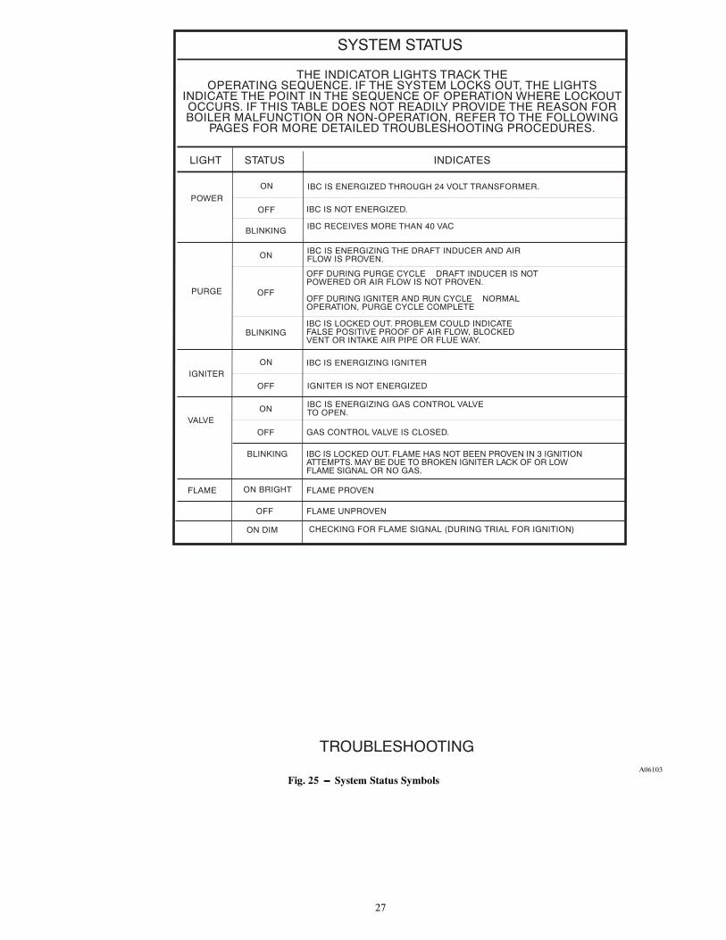
27
SYSTEM STATUS
THE INDICATOR LIGHTS TRACK THEOPERATING SEQUENCE. IF THE SYSTEM LOCKS OUT, THE LIGHTS
INDICATE THE POINT IN THE SEQUENCE OF OPERATION WHERE LOCKOUTOCCURS. IF THIS TABLE DOES NOT READILY PROVIDE THE REASON FORBOILER MALFUNCTION OR NON-OPERATION, REFER TO THE FOLLOWING
PAGES FOR MORE DETAILED TROUBLESHOOTING PROCEDURES.
LIGHT STATUS INDICATES
POWER
PURGE
IGNITER
VALVE
FLAME
ON
OFF
IBC IS ENERGIZED THROUGH 24 VOLT TRANSFORMER.ON
ON
ON
OFF
OFF
OFF
BLINKING
IBC IS NOT ENERGIZED.
IBC IS ENERGIZING THE DRAFT INDUCER AND AIRFLOW IS PROVEN.
OFF DURING PURGE CYCLE � DRAFT INDUCER IS NOTPOWERED OR AIR FLOW IS NOT PROVEN.
OFF DURING IGNITER AND RUN CYCLE � NORMALOPERATION, PURGE CYCLE COMPLETE
IBC IS LOCKED OUT. PROBLEM COULD INDICATEFALSE POSITIVE PROOF OF AIR FLOW, BLOCKEDVENT OR INTAKE AIR PIPE OR FLUE WAY.
IBC IS ENERGIZING IGNITER
IGNITER IS NOT ENERGIZED
IBC IS ENERGIZING GAS CONTROL VALVETO OPEN.
GAS CONTROL VALVE IS CLOSED.
FLAME PROVEN
FLAME UNPROVEN
TROUBLESHOOTING
OFF
IBC RECEIVES MORE THAN 40 VACBLINKING
IBC IS LOCKED OUT. FLAME HAS NOT BEEN PROVEN IN 3 IGNITIONATTEMPTS. MAY BE DUE TO BROKEN IGNITER LACK OF OR LOWFLAME SIGNAL OR NO GAS.
BLINKING
ON BRIGHT
ON DIM CHECKING FOR FLAME SIGNAL (DURING TRIAL FOR IGNITION)
A06103
Fig. 25 --- System Status Symbols

28
ELECTRICAL SHOCK HAZARD
Failure to follow this warning could result in personalinjury or death.
The following procedures may expose you todangerous line voltage. Use caution to avoid touchinglive electrical contacts. Service must be performed by atrained, experienced service technician.
What to do if you smell gas:--Do not try to light any appliance--Do not touch any electrical switch; do not use anyphone in your building--Immediately call your gas supplier from a neighbor’sphone. Follow the gas supplier’s instructions--If you cannot reach your gas supplier, call the firedepartment
Should overheating occur or the gas supply fail to shutoff, do not turn off or disconnect the electrical supply tothe pump. Instead, shut off the gas at a location externalto the appliance.
Do not use the boiler if any part of the gas controlsystem has been under water. A qualified servicetechnician should inspect the boiler and replace any partof the control system and any gas control which hasbeen under water.
Use only your hand to turn the gas control knob. Neveruse tools. If the knob will not turn by hand, do not tryto repair it. Force or attempted repair may result in afire or explosion.
! WARNING
Fig. 26 --- Electrical Shock Hazard Warning

29
A04070
Fig. 27 --- Troubleshooting Chart No. 1

30
CHECK THAT CIRCUIT BREAKERS IS ON ORFUSES ARE OK AT THE ELECTRICAL PANEL
CHECK THAT SERVICE SWITCH IS ON
OK
ON
NO
CHART 1
CHECK CASTING TEMPERATURE SAFETYSWITCH. PUSH RESET BUTTON ON SWITCH.CONTACTS OPEN (BUTTON UP) OR CLOSED
(BUTTON DOWN)?
CLOSED
CHECK WIRING TO IBC. I20 VAC BETWEENTERMINALS 1 AND 3 AT WIRING HARNESS
PLUG CN7?
YES
120 VAC BETWEEN TERMINALS 1 AND 3 ATCONNECTOR CN3 OR IBC?
YES
120 VAC AT TRANSFORMER PRIMARYTERMINALS?
YES
24 VAC AT TRANSFORMER SECONDARYTERMINALS?
YES
YES
24 VAC AT WIRING HARNESS PLUG CN2?
REPLACE IBC
NO
NO
NO
NO REPLACE IBC
REPAIR WIRING TO TRANSFORMER
REPLACE TRANSFORMER
PUSH RESET BUTTON ON CASTING TEMPSAFETY SWITCH. CHECK CONTINUITY OF
CASTING TEMP. SAFETY SWITCH CONTACTS.CONACTS OPEN OR CLOSED?
CLOSED OPEN
REPLACE CAST. TEMP.SAFETY SWITCH.
REPLACE/REPAIR WIRING FROMTRANSFORMER TO IBC
REPLACE IBC
REPLACE/REPAIR WIRING FROM IBC TOCIRCULATOR
NO
NO
YES
YES
NO
CHART 1
CHECK FOR 120 VAC BETWEEN TERMINALS 1AND 3 AT CONNECTOR CN5 ON IBC?
CHECK FOR 120 VAC AT CIRCULATOR
REPAIR/REPLACE CIRCULATOR
TROUBLESHOOTING CHART 2
NO
OPEN
REPLACE/REPAIR WIRING FROM SERVICESWITCH TO IBC
CHECK WATER LEVEL IN BOILER. CHECKFOR AIR TRAPPED IN TOP OF BOILER.
CONTACTS WILL NOT STAY CLOSED UNTILBOILER COOLS OFF.
TROUBLESHOOTING
A99352
Fig. 28 --- Troubleshooting Chart No. 2

31
ARE ORIFICES INNEGATIVE PRESSURE
HOSE CLEAR?
CLEAN OUT BLOCKAGEAT ORIFICES
CHART 1OPEN
BLOWER STARTS
PURGE LIGHT ON?
CHECK FOR 120 VACBETWEEN TERMINALS 1AND 3 AT CONNECTOR
CN4 ON IBC
REPLACE IBC
CHECK FOR 120 VAC ATBLOWER LEADS
ON WIRING HARNESS
REPAIR/REPLACEWIRING FROM IBC
TO DRAFT INDUCER
REPAIR/REPLACEBLOWER
CONTACTS OPENIBC WAITS UP TO 5MINUTES FOR NORMALLY
OPEN AIR PRESSURE SWITCH CONTACTS TO
CLOSE, INDICATINGBLOWER SUCTION
IS PRESENT
ARE VENT PIPE ANDAIR INTAKE PIPE CLEAR
(NO BLOCKAGE)
CLEAN OUT VENT PIPEAND/OR AIR INTAKE PIPE.
CHECK FOR SAGS OR LOW SPOTS WHERE
CONDENSATE MAY PUDDLE AND BLOCK THE VENT
CHECK AIR PRESSURESWITCH PER
INSTRUCTIONS ON FOLLOWING PAGES. ARESAMPLING LINES CLEAR
AND CONNECTED PROPERLY?
CLEAN OUT SAMPLINGLINES OR REPLACEDEFECTIVE SWITCH
CHECK FLUE PASSAGESIN BOILER PER
�MAINTENANCE AND CLEANING�. ARE FLUEPASSAGES IN BOILER
CLEAN?
CLEAN BOILER FLUEPASSAGES PER
MAINTENANCE AND CLEANING INSTRUCTIONS
CHECK DRAFT INDUCERMOTOR RPM. IS IT
3400-3600?
CHECK FOR BROKEN ORLOOSE IMPELLER ON DRAFT INDUCER AND
REPLACE BLOWERIF FOUND TO BE
BROKEN OR LOOSE
REPLACE BLOWER
REPLACE IBC
15 SECOND PRE PURGE COMPLETE.PURGE LIGHT OFF. SIMULTANEOUSLY
IGNITER LIGHT IS ON AS IGNITORCIRCUIT IS ENERGIZED
CHART 4
TROUBLESHOOTING
TROUBLE SHOOTING CHART 3
YES
NO
YES
YES
YES
YES
YES
NO
NO
NO
NO
NO
YES
YES
YES
YES
NO
NONO
A06155
Fig. 29 --- Troubleshooting Chart No. 3

32
AFTER 20 SECONDIGNITER WARM UP, GASVALVE IS ENERGIZEDVALVE LIGHT ON.
1 SECOND LATER POWERIS REMOVED FROMIGNITER/SENSOR
POWER LIGHT IS OFF.DOES MAIN BURNER LIGHT?
TROUBLESHOOTING CHART 4CHART 3YES
IGNITER/SENSOR WARMSUP AND GLOWS YELLOW/
ORANGE DURING 20SECOND WARM UP
CHECK FOR 120 VACBETWEEN TERMINALS 1AND 2 AT CONNECTORCN1 ON IBC (DURINGIGNITER WARM UP)
CHECK FOR 120 VAC ATIGNITER/SENSOR LEADS
ON WIRING HARNESS(DURING IGNITER
WARM UP)
CHECK FOR 24 VACACROSS TERMINALS MV
ON THE GASCONTROL. WHILE VALVE/FLAME INDICATOR LIGHT
IS ON
REPLACE IBC
REPAIR/REPLACE WIRINGFROM IBC TO IGNITER/
SENSOR
REPLACE IGNITER/SENSOR
CHECK FOR 24 VACACROSS TERMINALSCN6-Z AND CN6-5 ON
IBC, WHILE THE VALVE/FLAME LED IS LIT
REPAIR/REPLACE WIRINGBETWEEN IBC AND
GAS CONTROL
REPLACE IBC
YES YES
YES
YES
YES
YES
NO NO
NO
NO NONO
NO
NO NO
CHART 5 CHART 5
YES YES
YES
CHECK IF IGNITER/SENSOR POSITION IS OK?TIP SHOULD BE SLANTED
TOWARDS BURNER
RESTORE IGNITER/SENSORTO CORRECT POSITION
DO NOT RELOCATE
CHECK GAS SUPPLYPRESSURE AT INLET
PRESSURE TAPPING ONGAS CONTROL. IS GASPRESSURE GREATER
THAN 4.0" W.C.?
ARE ALL MANUAL SHUT-OFFS IN THE GAS
SUPPLY LINE AND ONTHE GAS CONTROL IN
THE OPEN OR ONPOSITION?
CONTACT THE GASUTILITY TO TURN THE
GAS ON
OPEN OR TURN ON ALLMANUAL SHUTOFFS
TROUBLESHOOTING
A04072
Fig. 30 --- Troubleshooting Chart No. 4

33
A04073
Fig. 31 --- Troubleshooting Chart No. 5

34
ADJUST RATE AS DESCRIBED INTHE CHECK OUT PROCEDUREAND ADJUSTMENT SECTION OF
THE MANUAL.
VALVE LIGHT OFF.
THEN TURNS OFF.
CHECK FIRING RATE OF UNIT.IS UNIT FIRING AT THE CORRECT RATE?
DOES THIS UNIT USE LP GAS.
REPLACE GAS CONTROL
CHECK GAS ORIFACE SIZEIS GAS ORIFICE SIZE CORRECT.
CHECK REPAIR PARTS LISTFOR CORRECT SIZE. IS GAS
ORIFICE CLEAR OF BLOCKAGE.
DOES DRAFT BLOWERSTOP AFTER 30
SECOND POST PURGE?
A04074
Fig. 32 --- Troubleshooting Chart No. 6

35
REPAIR PARTS
11b
129
13
14
15
16
17
18
161
8
7
6
519
4
3
2
10
11a
A04076
Fig. 33 --- Jacket and Base Assembly

36
JACKET AND BASE ASSEMBLYItem Part No. Description Quantity1 2272144 Base Replacement Kit 12 650001028 Control Panel 13 146622803 Integrated Boiler Control 14 550001339 40 VA Transformer Kit 15 14631316 4” x 4” x 2---1/8” J---Box 16 14631319 Switch P & S 17 14631318 J---Box Plate Cover 1
8 2272152AB Jacket Panel Left Side Kit(Includes Items 15 and 16) 1
9 2272151AB Jacket Panel Right Side Kit(Includes Items 15 and 16) 1
10 750701031AB Jacket Panel, Back 111a 2370007AB Jacket Panel, Top Left 111b 2370008AB Jacket Panel, Top Right 112 12695074 Screw 10 x 1/2” ZP 1213 750001034 Jacket Tie Bar 114 14695060 Screw 10 x 1/2” Tech 1415 1225013 Tap Bumper 116 1225012 Latch and Clip Kit 117 14631095 Door Pull18 2272150AB Jacket Service Door Replacement Kit
(Includes Items 16 and 17)1
19 2485001 Pressure Switch Mounting Plate 1* 1263010 Harness Low Water Cutoff 1* 1263020 Wiring Harness 1* 14631174 2---1/2” Plug 1* 2272164AB Jacket, Complete Replacement Kit
(Includes Items 8, 9, 11a, and 18) 1
*Not Shown

37
129 1/2" LONG
37" LONG
2
45
61 3/8" LONG
7
83 3/4" LONG
7
92" LONG
7
83 3/4" LONG
10
1112" LONG
A06154
Fig. 34 --- Exhaust Tee and Condensate Assembly
EXHAUST TEE AND CONDENSATE ASSEMBLYItem Part Number Description Quantity
1 1400008 Vent Pipe 2” CPVCSCH---40 x 29---1/2” Long
1
2 14631305 Tee 2” CPVC SCH---80 13 1400008 Vent Pipe 2” CPVC SCH---40 x 7” Long 14 240005852 Cleanout PVC 2” 1
5 1001002 PVC Fitting 1/2” NPT Male x 1/2”Slip Female 1
6 140014 Pipe 1/2” PVC SCH---40 x 1---3/8” 17 1190005 Elbow 1/2” x 90 deg. PVC SCH---40 38 1400014 Pipe 1/2” PVC SCH---40 x 3---3/4” 29 1400014 Pipe 1/2” PVC SCH---40 x 2” 110 1510012 Tee 1/2” x 1/2” x 1/2” PVC SCH---40 111 1400014 Pipe 1/2” PVC SCH---40 x 12” 1* KGAVT0601CVT 3” Concentric Vent 1
*Not Shown

38
5
67 8 9
10
43
2
1
28
29
27
26
25
24
23 22
21
20
19
18
1716
15
1413
1211
31
30
30
A06153
Fig. 35 --- Boiler Block and Piping Assembly

39
BOILER BLOCK AND PIPING ASSEMBLYItem Part Number Description Quantity1 2272160 Replacement Block Kit
(Includes Items 2 and 30)1
2 1395002 1---1/4” Plug Cast Iron Square Head Plug 123 14631301 Hose 3” Long x 2---3/8 I.D. x 2---3/4” O.D. 14 1400008 Vent Pipe 2” CPVC SCH---40 x 7” Long 15 1310015 Nipple, Black 1---1/2” Close 16 14622000 Valve BLR DR 3/4” 17 1510010 Reducing Tee 1---1/2” x 1---1/4” x 3/4” 18 1190004 1---1/4” Street Elbow BLK 90_ 19 1310002 Nipple Std Black 1---1/4” x 3/4” 110 1190002 Elbow 1---1/4” x 90_ 111 14631004 Sight Glass Adapter 112 14619002 Observation Port 3/4” 113 1230010 Fitting, Brass 1/8” NPT x 3/16” Straight Barb 114 14631324 Aquastat 115 14662804 Well Control ½” 116 14693004 ¾” x ½” Std. Black Bushing 117 14693204 1½” x 1¼” Std. Black Bushing 118 PF06501 1¼” x 7” NPT Std. Black Pipe Nipple 119 1260006SP Temp/Pressure Gauge 2” Shank 120 1060002 ¾” x ¼” Std. Black Iron Bushing 121 PF05901 1¼” x 1¼” x ¾” Std. Black Tee 122 14693001 3/4” x 1/8” Black Bushing 123 1580006 Air Purger w/Check Valve 124 14622011 ¾” Relief Valve 125 14607002 ¾” x 6½” Std. Black Nipple 126 14695802 Screw Soc HD Cap 8---32 x 3/16” 227 1500005 Casting Temperature Switch 128 2272137 Replacement LWCO Kit 129 14693005 1” x ¾” Black Bushing 130 1395004 1” Cast Iron Square Head Solid Plug 231 14631302 Clamp, Stainless Steel #44 2* CI---001.03 Circulator Pump w/Flange, Taco 1
* Not Shown

40
6
2 1
3
4 5
9
8
7
A04079
Fig. 36 --- Burner Assembly
BURNER ASSEMBLYItem Part Number Description Quantity
1 2272149 Burner Replacement Kit(Includes Items 2 and 3) 1
2 1250009 Burner/Casting Gasket 13 1250008 Burner/Flue Adapter Gasket 14 1210122 Flue Adapter 15 14695810 Hex Nut w/Serrated Washer ¼” x 20 56 1450011 Threaded Stud ¼” x 20 x 1½” 57 1250010 Igniter/Mixer Gasket 18 1264005 Hot Surface Igniter 19 14695809 Screw 10---32 x 3/8” 2
* 2272133 Hot Surface Igniter Kit(Includes Items 7, 8 and 9) 1
* Not Shown

41
3
2
12"
13"
15 1/2"
SIGHT GLASS& ADAPTER
413 1/4"
7
4 6"4 16 1/2"
GAS VALVE
8
6
4
1 4"
4 4"
5
9
9
AIR INLETCONNECTION
2 @ 2" EA.
A06107
Fig. 37 --- Mixer and Air Pressure Switch Assembly
MIXER AND AIR PRESSURE SWITCH ASSEMBLYItemItem
ItemPart Number Description Quantity
1 14629003 Silicone Tubing, 3/16” I.D. Varies2 1401004 Air Pressure Switch 3.5 IWC 13 1401002 Air Pressure Switch Clip 24 1552004 Orange Silicone Tubing, 3/16” I.D. Varies5 1401003 Air Pressure Switch 1/2 IWC 16 1230006 3/16” Black Vinyl 2
7 1510009 Plastic Barbed Hose Tee, 3/16” I.D. 58 1110001 Rotor Clamp 229 PB---002.02 Pilot Orifice, BBR10 2

42
1
4
3
6
5
7
2
BLOWER GASKET
A04081
Fig. 38 --- Flue Adapter and Exhauster Assembly
FLUE ADAPTER AND EXHAUSTER ASSEMBLYItem Part Number Description Quantity
1 2272145 Blower Replacement Kit(Includes Item 13) 1
2
2272140 Gas Valve Replacement Kit (125 Only) 12272141 Gas Valve Replacement Kit (150 Only) 12272142 Gas Valve Replacement Kit (175 Only) 12272143 Gas Valve Replacement Kit (200 Only) 1
3 14631311 2” x 1½” Flex Coupling 14 1570038 Ball Valve ½” (Blue) 15 1400007 Vent Pipe 2” PVC SCH---40 8” Long 16 1230011 Fitting PE 1/8” NPT x 3/16” Barb 90_ 17 1450012 Screw T25 Torx 28 14693801 Elbow Street Mall Iron ½”---90 PWX 29 14607301 Nipple Blk. Std. ½” NPT x 3” 210 1225015 Cap ½” Cast Iron 111 14657015 Tee Black ½” 112 14607803 Nipple Blk. Std. ½” x 4½” 113 1250021 Gasket, Cork, Venturi 114 1250007 Gasket, Fan Flue Adapter 1

43
Table 7—Conversion Kits -- Nat to LP for 125--200MBH
MODEL # KIT # INCLUDES:
BW9AAN000125 KBANP1401DNK
Plastic Bag 3 x 6 x 18Orifice LP Model 125, 3.9MM
Label PropaneLiterature, Conversion 125/200
Key, Torx T---20Label Propane Only Data Plate
BW9AAN000150 KBANP1501DNK
Plastic Bag 3 x 6 x 18Orifice LP Model 150, 4.2MM
Label PropaneLiterature, Conversion 125/200
Key, Torx T---20Label Propane Only Data Plate
BW9AAN000175 KBANP1601DNK
Plastic Bag 3 x 6 x 18Orifice LP Model 175, 5.2MM
Label PropaneLiterature, Conversion 125/200
Key, Torx T---20Label Propane Only Data Plate
BW9AAN000200 KBANP1701DNK
Plastic Bag 3 x 6 x 18Orifice LP Model 200, 6.0MM
Label PropaneLiterature, Conversion 125/200
Key, Torx T---20Label Propane Only Data Plate
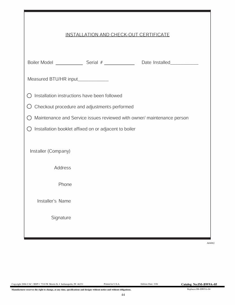
44
INSTALLATION AND CHECK-OUT CERTIFICATE
Boiler Model Serial # Date Installed___________
Measured BTU/HR input____________
Installation instructions have been followed
Checkout procedure and adjustments performed
Maintenance and Service issues reviewed with owner/ maintenance person
Installation booklet affixed on or adjacent to boiler
Installer (Company)
Address
Phone
Installer'sí Name
Signature
A04082
Copyright 2006 CAC / BDP S 7310 W. Morris St. S Indianapolis, IN 46231
Manufacturer reserves the right to change, at any time, specifications and designs without notice and without obligations.
Catalog No:IM--BW9A--05
Replaces:IM--BW9A--04
Printed in U.S.A. Edition Date: 3/06