hornby - railroom electronics · either contact hornby via the hornby dcc website (), or write to...
TRANSCRIPT

‘Elite’ Unit – Operator’s Manual
Hornby Hobbies Limited, Margate, Kent CT9 4JX. Tel: +44 (0) 1843 233525
For more information visit:www.hornby.comM00000
Elite HBook Cover Section 13/3/07 13:07 Page 1

Digital Command ControlDigital Command Control
For more information visit:www.hornby.com
Welcome to the Hornby Digital World of model railways.You are about to enjoy a new and exciting experiencewhen it comes to controlling and operating a model railway.
Using the keypad and rotary controls that are on the Elite unit locomotives can be “called up” individually andoperated just like the real thing. Imagine a busy marshalling yard where the locomotives are positioned closetogether and where by using the Hornby Elite Digital Controller Hornby digital locomotives can bemanoeuvred from one place to another without having to worry about the complexities of connecting metresof wiring to a bank of switches and isolating sections and hoping the whole thing will work!
The Hornby Elite Digital Control has the ability to address 254 locomotives and depending on the accessory/point decoders used up to 255 points or solenoid operated accessories. The following instructions are a guideon how to get the best from your Hornby Elite Digital Control. Please take a little time to carefully readthrough the instructions before you start to use the Hornby Elite. Should you have any questions then you caneither contact Hornby via the Hornby DCC website (www.hornby.com), or write to Hornby using the emailaddress: [email protected]
The Hornby Elite is an advanced digital controller and therefore it is important that you read and fully understandthe instructions before operation. Please also be aware that that for the majority of programming for bothlocomotives and accessories a Programming Track must be used.
The real way to run a railway!
51
Notes LocomotiveAddress
Elite HBook Cover Section 13/3/07 13:07 Page 3
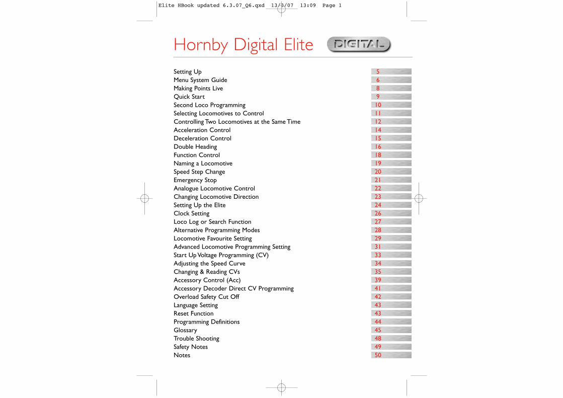
Hornby Digital Elite Setting Up 5Menu System Guide 6Making Points Live 8Quick Start 9Second Loco Programming 10Selecting Locomotives to Control 11Controlling Two Locomotives at the Same Time 12Acceleration Control 14Deceleration Control 15Double Heading 16Function Control 18Naming a Locomotive 19Speed Step Change 20Emergency Stop 21Analogue Locomotive Control 22Changing Locomotive Direction 23Setting Up the Elite 24Clock Setting 26Loco Log or Search Function 27Alternative Programming Modes 28Locomotive Favourite Setting 29Advanced Locomotive Programming Setting 31Start Up Voltage Programming (CV) 33Adjusting the Speed Curve 34Changing & Reading CVs 35Accessory Control (Acc) 39Accessory Decoder Direct CV Programming 41Overload Safety Cut Off 42Language Setting 43Reset Function 43Programming Definitions 44Glossary 45Trouble Shooting 48Safety Notes 49Notes 50
Elite HBook updated 6.3.07_Q6.qxd 13/3/07 13:09 Page 1
For more information visit:www.hornby.com
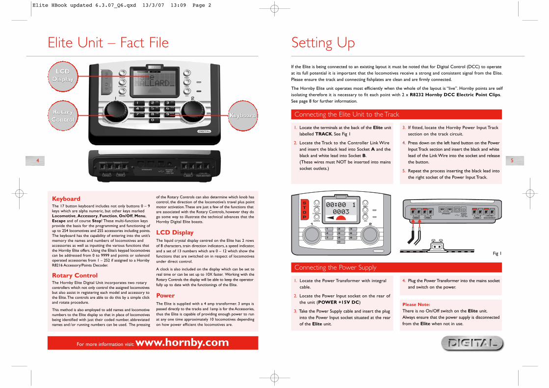
Connecting the Elite Unit to the Track
1. Locate the terminals at the back of the Elite unitlabelled TRACK. See Fig 1
2. Locate the Track to the Controller Link Wireand insert the black lead into Socket A and theblack and white lead into Socket B.(These wires must NOT be inserted into mainssocket outlets.)
3. If fitted, locate the Hornby Power Input Tracksection on the track circuit.
4. Press down on the left hand button on the PowerInput Track section and insert the black and whitelead of the Link Wire into the socket and releasethe button.
5. Repeat the process inserting the black lead intothe right socket of the Power Input Track.
Connecting the Power Supply
1. Locate the Power Transformer with integralcable.
2. Locate the Power Input socket on the rear ofthe unit (POWER +15V DC)
3. Take the Power Supply cable and insert the pluginto the Power Input socket situated at the rearof the Elite unit.
4. Plug the Power Transformer into the mains socketand switch on the power.
KeyboardThe 17 button keyboard includes not only buttons 0 – 9keys which are alpha numeric, but other keys markedLocomotive, Accessory, Function, On/Off, Menu,Escape and of course Stop! These multi-function keysprovide the basis for the programming and functioning ofup to 254 locomotives and 255 accessories including points.The keyboard has the capability of entering into the unit’smemory the names and numbers of locomotives andaccessories as well as inputting the various functions thatthe Hornby Elite offers. Using the Elite’s keypad locomotivescan be addressed from 0 to 9999 and points or solenoidoperated accessories from 1 – 252 if assigned to a HornbyR8216 Accessory/Points Decoder.
Rotary ControlThe Hornby Elite Digital Unit incorporates two rotarycontrollers which not only control the assigned locomotivesbut also assist in registering each model and accessory tothe Elite.The controls are able to do this by a simple clickand rotate procedure.
This method is also employed to add names and locomotivenumbers to the Elite display so that in place of locomotivesbeing identified with just their coded number, abbreviatednames and /or running numbers can be used. The pressing
of the Rotary Controls can also determine which knob hascontrol, the direction of the locomotive’s travel plus pointmotor activation.These are just a few of the functions thatare associated with the Rotary Controls, however they dogo some way to illustrate the technical advances that theHornby Digital Elite boasts.
LCD DisplayThe liquid crystal display centred on the Elite has 2 rowsof 8 characters, train direction indicators, a speed indicator,and a set of 13 numbers which are 0 – 12 which show thefunctions that are switched on in respect of locomotivesunder direct control.
A clock is also included on the display which can be set toreal time or can be set up to 10X faster. Working with theRotary Controls the display will be able to keep the operatorfully up to date with the functionings of the Elite.
PowerThe Elite is supplied with a 4 amp transformer. 3 amps ispassed directly to the tracks and 1amp is for the Accessories,thus the Elite is capable of providing enough power to runat any one time approximately 10 locomotives dependingon how power efficient the locomotives are.
If the Elite is being connected to an existing layout it must be noted that for Digital Control (DCC) to operateat its full potential it is important that the locomotives receive a strong and consistent signal from the Elite.Please ensure the track and connecting fishplates are clean and are firmly connected.
The Hornby Elite unit operates most efficiently when the whole of the layout is “live”. Hornby points are selfisolating therefore it is necessary to fit each point with 2 x R8232 Hornby DCC Electric Point Clips.See page 8 for further information.
Setting Up
4 5
Elite Unit – Fact File
KeyboardRotaryControl
LCDDisplay
RotaryControl
LCDDisplay
Keyboard
Fig 1
4
Please Note:There is no On/Off switch on the Elite unit.Always ensure that the power supply is disconnectedfrom the Elite when not in use.
Elite HBook updated 6.3.07_Q6.qxd 13/3/07 13:09 Page 2
DirectRegPaged
Operate
Features
Direct/Reg/PagedAdr:0003
OperateAdr:0003
FeaturesAdr:0003
AddressReadWrite – Adr:0003
Accel000
Decel000
StartV000
Name–
Name–
Steps128, 28,14
FavYes/No
CVRead
Write
VersionXXX
Man IDXXX– CV 0001
R– CV 0001 W
CVRead
Write
VersionXXX
Man IDXXX– CV 0001
R– CV 0001 W
ConfigDir
Power
RailCom
SP.Table
Address
Decoder
– Normal– Reverse
– DCC Only– DCC & DC
– Enabled– Disabled
– CV#2#5#6– CV#67 – 94
– Short– Extended
– Multi– Acc
Loco
DirectRegPaged
Features
Direct/Reg/PagedAdr:0003
FeaturesAdr:0003
AddressReadWrite – Adr:0003
Train 0On/Off
RailComOn/Off
ClockOn/Off
Set Clk00:00
Clock X00
Loco LogName/Address
FavOn/Off
LanguageEnglishFrenchItalianSpanishGerman
ResetConfirm
Acc
Unit
Gp CreateGp Adr – Adr:0003Loco1 – Adr:0001Loco2 – Adr:0002
Gp DissolveGp – Adr:0003Dissolved
Dbl Hdr
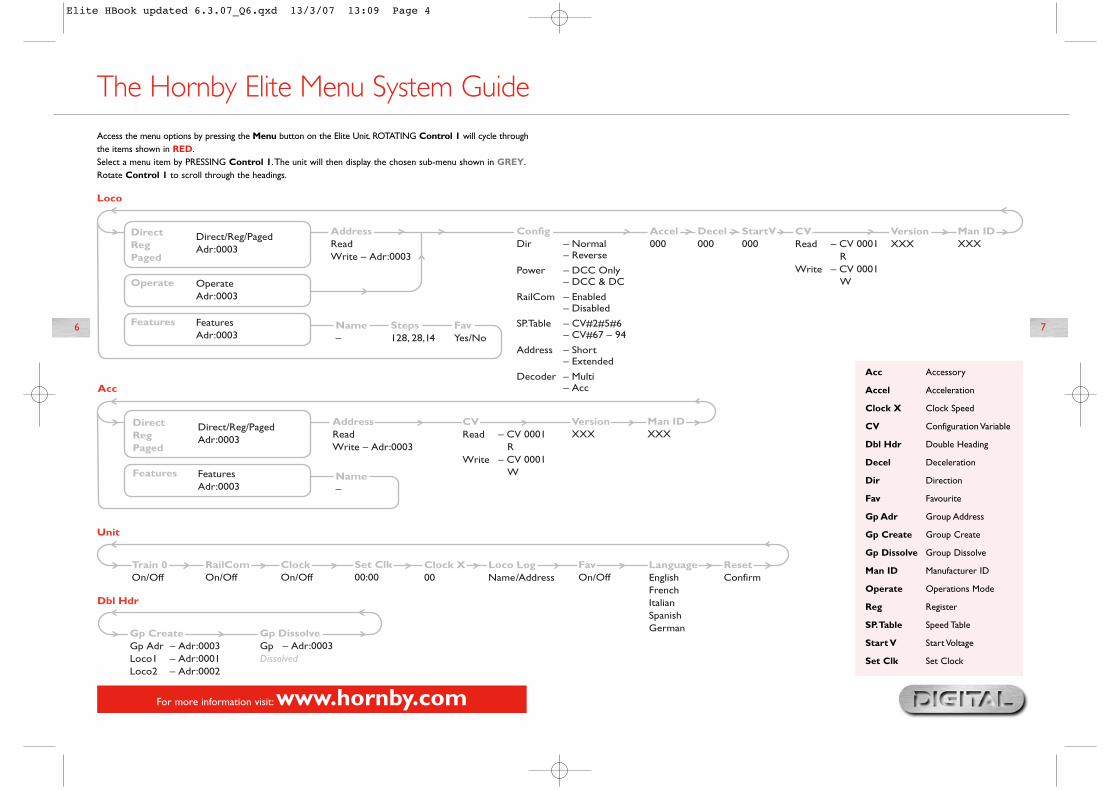
Access the menu options by pressing the Menu button on the Elite Unit. ROTATING Control 1 will cycle throughthe items shown in RED.Select a menu item by PRESSING Control 1.The unit will then display the chosen sub-menu shown in GREY.Rotate Control 1 to scroll through the headings.
The Hornby Elite Menu System Guide
6 7
For more information visit:www.hornby.com
Acc Accessory
Accel Acceleration
Clock X Clock Speed
CV Configuration Variable
Dbl Hdr Double Heading
Decel Deceleration
Dir Direction
Fav Favourite
Gp Adr Group Address
Gp Create Group Create
Gp Dissolve Group Dissolve
Man ID Manufacturer ID
Operate Operations Mode
Reg Register
SP.Table Speed Table
Start V Start Voltage
Set Clk Set Clock
Elite HBook updated 6.3.07_Q6.qxd 13/3/07 13:09 Page 4
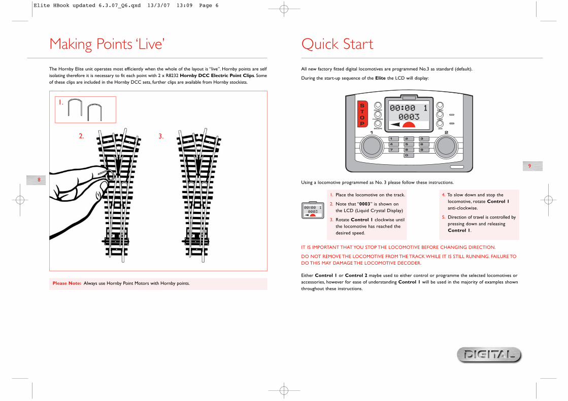
1.
2. 3.
1. Place the locomotive on the track.
2. Note that “0003” is shown onthe LCD (Liquid Crystal Display)
3. Rotate Control 1 clockwise untilthe locomotive has reached thedesired speed.
4. To slow down and stop thelocomotive, rotate Control 1anti-clockwise.
5. Direction of travel is controlled bypressing down and releasing Control 1.
9
The Hornby Elite unit operates most efficiently when the whole of the layout is “live”. Hornby points are selfisolating therefore it is necessary to fit each point with 2 x R8232 Hornby DCC Electric Point Clips. Someof these clips are included in the Hornby DCC sets, further clips are available from Hornby stockists.
Making Points ‘Live’
Please Note: Always use Hornby Point Motors with Hornby points.
All new factory fitted digital locomotives are programmed No.3 as standard (default).
During the start-up sequence of the Elite the LCD will display:
Using a locomotive programmed as No. 3 please follow these instructions.
IT IS IMPORTANT THAT YOU STOP THE LOCOMOTIVE BEFORE CHANGING DIRECTION.
DO NOT REMOVE THE LOCOMOTIVE FROM THE TRACK WHILE IT IS STILL RUNNING. FAILURE TODO THIS MAY DAMAGE THE LOCOMOTIVE DECODER.
Either Control 1 or Control 2 maybe used to either control or programme the selected locomotives oraccessories, however for ease of understanding Control 1 will be used in the majority of examples shownthroughout these instructions.
Quick Start
8
Elite HBook updated 6.3.07_Q6.qxd 13/3/07 13:09 Page 6

The Elite Digital unit can support 4 types of locomotive programming modes: Direct, Register, Paged andOperation. For definitions please see page 28. As Direct Programming is now considered to be thefavoured protocol the following programming instructions are Direct based.
Before any programming can commence a Programming Track must be attached to the Elite Unit. A ProgrammingTrack will allow for both locomotives and Accessory / Point decoders to be programmed simply and easily. It mustbe noted that the majority of programming of locomotives and Accessory / Point decoders must be done usingthe Programming Track and not on the main track.
Second Loco Programming
11
The Hornby Elite Digital Control unit can have stored in its memory 254 digitally controlled locomotives and255 solenoid operated accessories.At any one time the Elite can in theory have running (providing the power isavailable) or on standby 64 locomotives.
This huge number is far in excess of what would be expected on any model railway layout, however should a 65thlocomotive be “called up”, one of the previous 64 will be removed from the queue.The locomotive that is returnedwill be the locomotive that has the lowest current speed address compared to the other 63.Alternatively, if all64 locomotives are stationary the locomotive with the lowest address will be removed from the queue.
Selecting Locomotives to Control
1. Connect the Elite to theProgramming Track as per thediagram.
2. Place the locomotive that you wish to programme on the track.
3. Press Menu button on the Elite.Screen shows “Loco”.
4. Press Control 1 to confirm. Screenshows “Direct”.
5. Press Control 1 to confirm. Screenshows “Address”.
6. Press Control 1 to confirm. Screenshows “Address Write”.
7. Press Control 1 to confirm. Screenshows “Adr:0003”
1. Press the Loco button.The Screenwill show the ‘active’ control knobnumber on the top row with thedefault locomotive (number 3) orthe last number ‘called up’ on thesecond row.
2. Select which Control you wish tooperate the locomotive – 1 or 2.For this example Control 2 will beused and loco 4 selected. Pressand then rotate Control 2 untilscreen shows “Contr 2 Adr:0004”
3. Alternatively to select a loco youcan type in the number using thekeypad. For this example“Loco 4” has been selected.
For more information visit:www.hornby.com
Fig 1
8. Rotate to desired number. PressControl 1 to confirm. For thisexample choose No. 1.
9. Press Control 1 once more. RedLED flashes five times. Screen shows“Address Adr:0001”. After theRed LED has stopped flashing thescreen shows “Address”.
10.The locomotive is now addressedas number 1.
11.To operate the locomotive pressMenu. Screen shows“00:00 1 0001”.The clock mayvary from 00:00.
12. Place the locomotive on the maintrack and control as described onpage 9.
4. Press and release Control 2.Screen shows “00:00 2 0004”.Rotate Control 2 and thelocomotive will move off. If you wishthe loco to move in the oppositedirection press Control 2.Thescreen will show that the directionarrow will have changed. See Fig 1.
IT IS IMPORTANT THAT YOU STOPTHE LOCO BEFORE CHANGINGDIRECTION.
DO NOT REMOVE THE LOCOFROM THE TRACK WHILE IT IS STILLRUNNING. FAILURE TO DO THISMAY DAMAGE THE LOCOMOTIVEDECODER.
10
Elite HBook updated 6.3.07_Q6.qxd 13/3/07 13:09 Page 8

13
For more information visit:www.hornby.com
12
Controlling two Locomotives at thesame time with the Elite
Allocation
1. Press Control 1. Screen shows“00:00 1 0003”.
2. Press Loco. Screen shows“Contr.1 Adr:0003”.
3. Rotate Control 1 until thelocomotive required is shown. Forthis example 10 has been selected.
4. Press Control 1. Screen shows“00:00 1 0010”.
5. Rotate Control 1 to move thelocomotive.
6. To control a second locomotivewith Control 2 press Control 2.Screen shows “00:00 2 0003” orthe last locomotive programmed.
7. Press Loco. Screen shows “Contr2 Adr:0010”. See Fig 1.
8. Rotate Control 2 until thelocomotive required is shown. Forthis example 20 has been selected.
9. Press Control 2. Screen shows“00:00 2 0020”.
The following procedure illustrates how to allocate specific locomotives to each of the Elite’s Controllers.
Controlling the Locomotives
1. To operate locomotive 10 turnControl 1. Screen changes toshow “00:00 1 0010”. See Fig 1.
2. To operate locomotive 20, turnControl 2. Screen changes to show“00:00 2 0020”.This action willresult in locomotive 10 continuingat its set speed.To bring locomotive10 back under control gently rotateControl 1.
Fig 1 Fig 1
Elite HBook updated 6.3.07_Q6.qxd 13/3/07 13:09 Page 10

1. Press Menu button on the Elite.Screen shows “Loco”.
2. Press Control 1 to confirm.Screen shows “Direct”.
3. Press Control 1 to confirm.Screen shows “Address”.
4. Rotate Control 1 until screenshows “Accel”.
5. Press Control 1. Screen shows“Accel 000”.
6. Rotate Control 1 until the desiredacceleration level is displayed.Alternatively, you can type in thelevel using the keypad. The lowerthe numbers entered the faster theacceleration; the higher the number(maximum 255), the slower theacceleration.
7. Press Control 1 and the red LEDwill flash five times. Screen shows“Accel”. See Fig 1.
8. Press Menu to return to the mainscreen.
For more information visit:www.hornby.com
14 15
Please Note:1 second per acceleration level (e.g.An acceleration level of 10 equals 10seconds approximately).
Elite Unit Acceleration Control Up to 255 acceleration and 255 deceleration levels can be programmed to each locomotive. For this exampleNo. 3 locomotive will be used. Before programming place the locomotive on the Programming Track.
Before programming the deceleration level ensure the locomotive is on the Programming Track.
Fig 1 Fig 1
Elite Unit Deceleration Control
1. Press Menu button on the Elite.Screen shows “Loco”.
2. Press Control 1 to confirm. Screenshows “Direct”.
3. Press Control 1. Screen shows“Address”.
4. Rotate Control 1 until screenshows “Decel”. See Fig 1.
5. Press Control 1 to confirm. Screenshows “Decel 000”.
Please Note:1 second per acceleration level (e.g. An acceleration level of 10equals 10 seconds approximately).
6. Rotate Control 1 until the desireddeceleration level is displayed.Alternatively, you can type in thedeceleration level using the keypad.The lower the number entered thefaster the deceleration; the higherthe number, (maximum 255) theslower the deceleration.
7. Press Control 1, red LED will flashfive times. Screen shows “Decel”.
8. Press Menu to return to the mainscreen.
Elite HBook updated 6.3.07_Q6.qxd 13/3/07 13:09 Page 12
1. Press the Menu button and rotateControl 1 until screen shows“Dbl Hdr”.
2. Press Control 1 and rotate untilscreen shows “Dissolve Gp”.
3. Press Control 1.The screen shows“Dissolve Adr: 01”.
4. Rotate Control 1 to show theConsist you wish to dissolve andpress Control 1 to confirm.
Dissolving a Double Headed Consist
Fig 1
1. Press Menu key. Screen shows“Loco”.
2. Rotate Control 1 until “Dbl Hdr”is displayed on the screen.
3. Press Control 1 to confirm.TheScreen will show either “DissolveGp” or “Create Gp”. RotateControl 1 until “Create Gp” isdisplayed.
4. Press Control 1. Screen shows“Create Adr: 01” as a defaultsetting.
5. Decide on an Address / Numberthat you wish to have as theDouble Heading number up to amaximum of 99. For this example10 has been chosen.
6. Rotate Control 1 until 10 isdisplayed.Alternatively you can, usingthe keyboard type in 10.
7. Press Control 1 to confirm. Screenshows “Loco 1 Adr: 0010”.
For more information visit:www.hornby.com
16 17
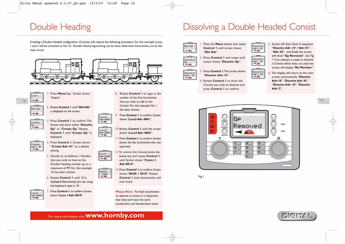
Double HeadingCreating a Double Headed configuration (Consist) will require the following procedure. For this example Locos1 and 2 will be consisted as No. 10. Double Head programming can be done while both locomotives are on themain circuit.
Please Note: For both locomotivesto operate in unison it is importantthat they each have the sameacceleration and deceleration levels.
5. Screen will then show in sequence“Dissolve Adr: 10”,“Adr: 01”,“Adr: 02”, and finally the screenwill show “Gp Removed”. See Fig1. If an attempt is made to dissolvea Consist which does not exist thescreen will display “No Member”.
6. The display will return to the mainscreen automatically “DissolveAdr:10”, “Dissolve Adr: 01”,“Dissolve Adr: 10”, “DissolveAdr: 2”.
8. Rotate Control 1 or type in thenumber of the first locomotivethat you wish to add to theConsist. For this example No. 1has been chosen.
9. Press Control 1 to confirm. Screenshows “Loco2 Adr: 0001”.
10. Rotate Control 1 until the screenshows “Loco2 Adr: 0002”.
11. Press Control 1 to confirm. Screenshows the last locomotive that wasoperated.
12.To control the Consist press theLoco key and rotate Control 1until Screen shows “Contr.:1Adr:0010”.
13. Press Control 1 to confirm. Screenshows “00:00 1 0010”. RotateControl 1 both locomotives willnow move.
Elite HBook updated 6.3.07_Q6.qxd 13/3/07 13:09 Page 14

For more information visit:www.hornby.com
18 19
Function Control The Elite Digital Control unit is capable of remotely switching on and off up to 13 functions which may havebeen incorporated into some locomotives. For example the locomotive may be fitted with lights, engine runningsounds and a horn or whistle etc. Using the Elite each function can be switched on or off.
1. Select which Control you wish touse to operate the locomotive – 1or 2. For this example Control 2will be chosen.
2. Press and release the Loco button.
3. The screen shows either the defaultnumber 3 or the number of the lastlocomotive that was controlled.
4. Rotate Control 2 until the numberof the locomotive you wish tocontrol is displayed.Alternatively youcan type in the number using thekeypad. For this example “Loco 1”will be selected.
5. Press Control 1 to confirm yourselection.
6. Press the Function key. The screenwill show the locomotive addressbeing used plus “Func.:00”. SeeFig 1.
7. Using the keypad type in the functionyou wish to operate. (0-12).
8. Press Control 2 to confirm.Thefunction is now operating.The screenwill show the number(s) of thefunction(s) that are switched on.
9. To switch off the function press theFunction key then the functionnumber and finally confirm bypressing and releasing Control 2.
10.Alternatively to switch off the lastfunction selected press the On/Offbutton located directly above theFunction button.
1. Press Menu. Screen shows“Loco”.
2. Press Control 1. Screen shows“Direct”.
3. Rotate Control 1 until screenshows “Features”.
4. Press Control 1. Screen shows“Features Adr:0001” or thelast locomotive operated. RotateControl 1 until loco desired isdisplayed.
5. Press Control 1. Screen shows“Name”.
6. Press Control 1. Press 6 twice.Screen shows “M”.
7. Press 2 twice. Screen shows“MA”.
8. Press 5 four times. Screen shows“MAL”.
9. Press 5 four times. Screen shows“MALL”.
10. Press 2 twice. Screen shows“MALLA”.
11. Press 7 four times. Screen shows“MALLAR”.
12. Press 3 twice. Screen shows“MALLARD”.
13. Should a mistake be made or youwish to remove the name rotateControl 1 anti-clockwise so thatthe cursor is underneath theincorrect letter. Press 0 twice andthe letter will disappear thencontinue as above.
14. Press Control 1 to confirm.“Name” is displayed. Press Menuto return to the main screen.
To Name a Locomotive
Naming a LocomotiveUsing the Elite alphanumeric keyboard locomotives can not only be given their own unique number but alsonamed. For this example the name “Mallard” will be used.
Fig 1
Elite HBook updated 6.3.07_Q6.qxd 13/3/07 13:09 Page 16
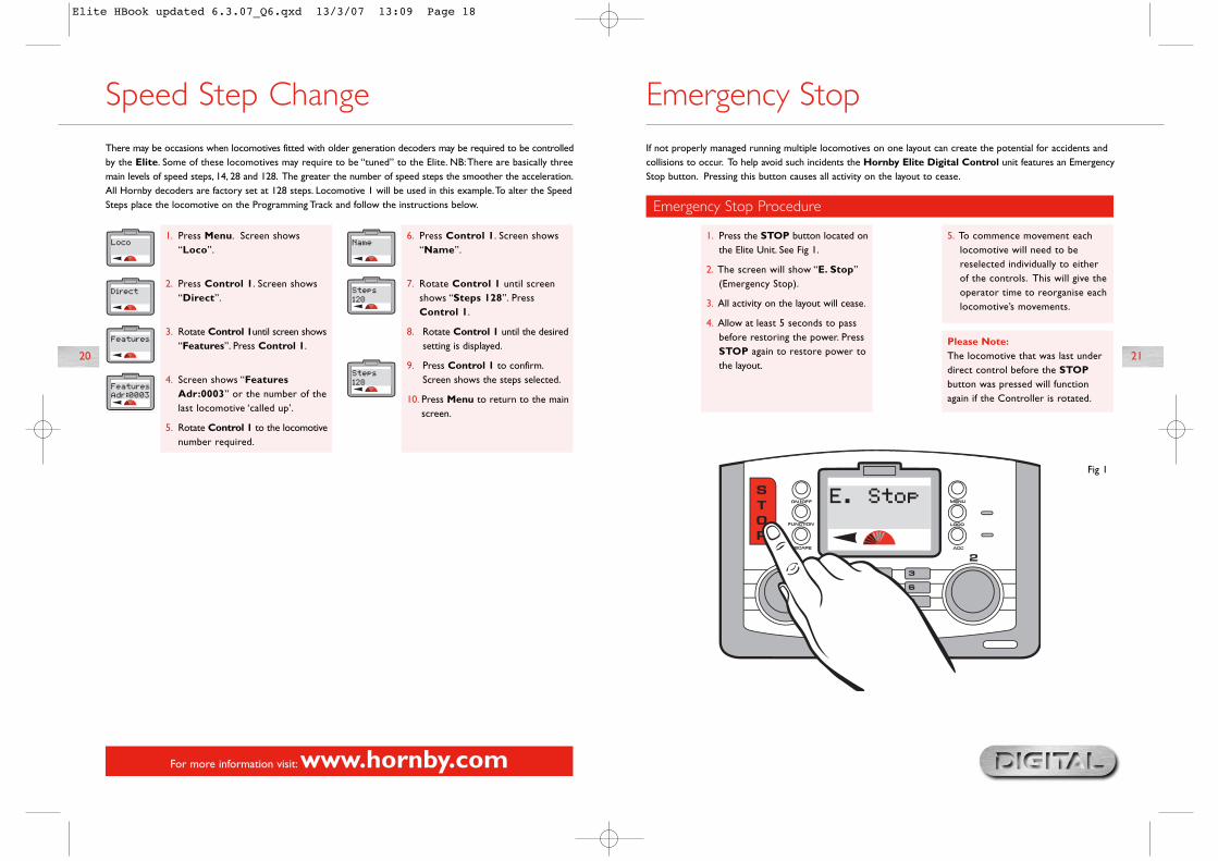
If not properly managed running multiple locomotives on one layout can create the potential for accidents andcollisions to occur. To help avoid such incidents the Hornby Elite Digital Control unit features an EmergencyStop button. Pressing this button causes all activity on the layout to cease.
Please Note:The locomotive that was last underdirect control before the STOPbutton was pressed will functionagain if the Controller is rotated.
For more information visit:www.hornby.com
20 21
Emergency Stop
Fig 1
Emergency Stop Procedure
1. Press the STOP button located onthe Elite Unit. See Fig 1.
2. The screen will show “E. Stop”(Emergency Stop).
3. All activity on the layout will cease.
4. Allow at least 5 seconds to passbefore restoring the power. PressSTOP again to restore power tothe layout.
5. To commence movement eachlocomotive will need to bereselected individually to eitherof the controls. This will give theoperator time to reorganise eachlocomotive’s movements.
Speed Step Change
1. Press Menu. Screen shows“Loco”.
2. Press Control 1. Screen shows“Direct”.
3. Rotate Control 1until screen shows“Features”. Press Control 1.
4. Screen shows “FeaturesAdr:0003” or the number of thelast locomotive ‘called up’.
5. Rotate Control 1 to the locomotivenumber required.
6. Press Control 1. Screen shows“Name”.
7. Rotate Control 1 until screenshows “Steps 128”. PressControl 1.
8. Rotate Control 1 until the desiredsetting is displayed.
9. Press Control 1 to confirm.Screen shows the steps selected.
10. Press Menu to return to the mainscreen.
There may be occasions when locomotives fitted with older generation decoders may be required to be controlledby the Elite. Some of these locomotives may require to be “tuned” to the Elite. NB:There are basically threemain levels of speed steps, 14, 28 and 128. The greater the number of speed steps the smoother the acceleration.All Hornby decoders are factory set at 128 steps. Locomotive 1 will be used in this example.To alter the SpeedSteps place the locomotive on the Programming Track and follow the instructions below.
Elite HBook updated 6.3.07_Q6.qxd 13/3/07 13:09 Page 18
Please Note:See page 25 (Train 0) for enablingthe analogue mode on the Elite.
Fig 1
For more information visit:www.hornby.com
22 23
Changing Locomotive DirectionSettingThe default direction of the locomotive can be altered using the Elite without taking it off the main track and todo this the following procedure will need to be used.
1. Press Menu button. Screen shows“Loco”.
2. Press Control 1 to confirm. Screenshows “Direct”.
3. Rotate Control 1 until “Operate”is displayed.
4. Press Control 1. Screen shows“Operate Adr:0003” or the lastlocomotive operated.
5. Press Control 1. Screen shows“Config”.
6. Press Control 1. Screen shows“Dir Normal”.
7. Rotate Control 1 to show“Normal” or “Reversed”. Selectthe preferred direction.
8. Press Control 1 to confirm.
9. Press Control 1 six times to skipfurther options. Screen shows“Config”. See Fig 1.
10. Press Menu to return to the mainmenu.
1. Press the Loco key and eitherrotate the chosen control knob ortype in “0”.
2. Press and release the selectedcontrol knob.
3. “Loco 0” can now be controlled.
4. Rotate the selected control knob.“Loco 0” will move forward. Pressand release the selected controlknob and the locomotive will reverse.
5. It must be noted that the control ofa locomotive which is not fitted witha decoder is noisy and does notsupport smooth control.
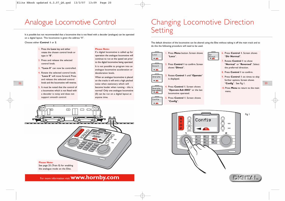
It is possible but not recommended that a locomotive that is not fitted with a decoder (analogue) can be operatedon a digital layout. This locomotive is given the address “0”.
Choose either Control 1 or 2.
Please Note:If a digital locomotive is called up foroperation the analogue locomotive willcontinue to run at the speed set priorto the digital locomotive being operated.
It is not possible to program into ananalogue locomotive acceleration ordeceleration levels.
When an analogue locomotive is placedon the tracks it will emit a high pitchednoise when stationary which willbecome louder when running – this isnormal! Only one analogue locomotive(0) can be run on a digital layout atanyone time.
Analogue Locomotive Control
Elite HBook updated 6.3.07_Q6.qxd 13/3/07 13:09 Page 20
Having now experienced the initial control and programming abilities of the Hornby Elite the next section of thisinstruction book is to explain the many additional features that this unit has to offer.
The Elite has several features that will need to be activated before the full potential of the unit can be experienced.The following are simple set up procedures for both the Hornby Elite Unit and locomotive programming.
25
For more information visit:www.hornby.com
24
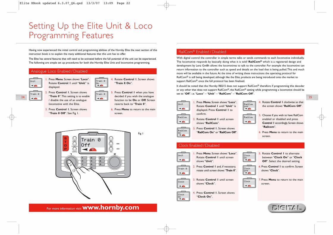
Setting Up the Elite Unit & LocoProgramming Features
Analogue Loco Enabled / Disabled
1. Press Menu. Screen shows “Loco”.Rotate Control 1 until “Unit” isdisplayed.
2. Press Control 1. Screen shows“Train 0”.This setting is to enable/ disable the use of an analoguelocomotive with the Elite.
3. Press Control 1. Screen shows“Train 0 Off”. See Fig 1.
4. Rotate Control 1. Screen shows“Train 0 On”.
5. Press Control 1 when you havedecided if you wish the analoguefunction to be On or Off. Screenreverts back to “Train 0”.
6. Press Menu to return to the mainscreen.
Fig 1
With digital control the controller in simple terms talks or sends commands to each locomotive individually.The locomotive responds by basically doing what it is told! RailCom® which is a registered design anddevelopment by Lenz GmBh allows the locomotives to talk to the controller. For example the locomotive canreturn information to the controller such as speed and details on the load that is being pulled.This and muchmore will be available in the future.At the time of writing these instructions the operating protocol forRailCom® is still being developed, although like the Elite, products are being introduced onto the market tosupport RailCom® once the full protocol has been finalised.
It should be noted that the Hornby R8215 does not support RailCom® therefore if programming this decoderor any other that does not support RailCom®, the RailCom® setting while programming a locomotive should beset to “Off”. i.e.“Loco” – “Unit” – “RailCom” – “RailCom Off”.
RailCom® Enabled / Disabled
1. Press Menu. Screen shows “Loco”.Rotate Control 1 until “Unit” isdisplayed. Press Control 1 toconfirm.
2. Rotate Control 1 until screenshows “RailCom”.
3. Press Control 1. Screen shows“RailCom On” or “RailCom Off”.
Clock Enabled / Disabled
1. Press Menu. Screen shows “Loco”.Rotate Control 1 until screenshows “Unit”.
2. Press Control 1 and, if necessary,rotate until screen shows “Train 0”.
3. Rotate Control 1 until screenshows “Clock”.
4. Press Control 1. Screen shows“Clock On”.
5. Rotate Control 1 to alternatebetween “Clock On” or “ClockOff”. Select the desired setting.
6. Press Control 1 to confirm. Screenshows “Clock”.
7. Press Menu to return to the mainscreen.
4. Rotate Control 1 clockwise so thatthe screen shows “RailCom Off”.
5. Choose if you wish to have RailComenabled or disabled and pressControl 1 accordingly. Screen shows“Railcom”.
6. Press Menu to return to the mainscreen.
Elite HBook updated 6.3.07_Q6.qxd 13/3/07 13:09 Page 22
Set Clock in Scale Time
1. Press Menu. Screen shows “Loco”.Rotate Control 1 until “Unit” isdisplayed.
2. Press Control 1 and, if necessary,rotate until screen shows “Train 0”.
3. Rotate Control 1 until screenshows “Clock X”.
4. Press Control 1. Screen shows“Clock X 00”.
5. Rotate Control 1 until the speedlevel required is shown on thescreen and press to confirm. Screenshows “Clock X”.
6. Press Menu to return to mainscreen.
For more information visit:www.hornby.com
26
Clock Setting
27
The Clock has the ability to be set at the actual time level or up to 10 times faster, 10 being the fastest. Havingset the time you may now wish to increase the speed of the clock.
Please note that the clock will immediately start functioning as soon as the Elite is powered up, therefore someof the clock times that you see on the main screen may not correspond with the graphic interpretations of themain screen shown throughout these instructions.
Set Clock in Real Time
1. Press Menu. Screen shows “Loco”.Rotate Control 1 until “Unit” isdisplayed.
2. Press Control 1 and, if necessary,rotate until screen shows “Train 0”.
3. Rotate Control 1 until “Set Clk”is displayed.
4. Press Control 1. “Set Clk 00:00”is displayed.
5. To set the hours rotate Control 1clockwise until the desired hourhas been reached.
6.To set the hours rotate Control 2clockwise.The hour is now set andthe minutes will flash.
7. Rotate Control 1 to the minutesrequired and press to confirm.Screen shows “Set Clk”.
8. If the hour setting is incorrect,rotate Control 2 anti-clockwiseuntil the hours flash and reset.
9. Press Menu to return to the mainscreen.
RailCom® is a registered trade mark of Lenz Systems.
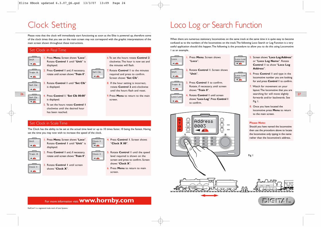
Loco Log or Search Function When there are numerous stationary locomotives on the same track at the same time it is quite easy to becomeconfused as to the numbers of the locomotives on the track.The following Loco Search or Log Function is a veryuseful application should this happen.The following is the procedure to allow you to do this using Locomotive1 as an example.
1. Press Menu. Screen shows“Loco”.
2. Rotate Control 1. Screen shows“Unit”.
3. Press Control 1 to confirm.Rotate, if necessary, until screenshows “Train 0”.
4. Rotate Control 1 until screenshows “Loco Log”. Press Control 1to confirm.
Please Note:Should you have named the locomotivethen use the procedure above to locatethe locomotive only typing in the namerather than the locomotive’s address.
5. Screen shows “Loco Log Address”or “Loco Log Name”. RotateControl 1 to show “Loco LogAddress”.
6. Press Control 1 and type in thelocomotive number you are lookingfor and press Control 1 to confirm.
7. Watch for movement on yourlayout.The locomotive that you aresearching for will move slightlyforwards and/or backwards. SeeFig 1.
8. Once you have located thelocomotive press Menu to returnto the main screen.
Fig 1
Elite HBook updated 6.3.07_Q6.qxd 13/3/07 13:09 Page 24
29
For more information visit:www.hornby.com
28
Alternative Programming Modes
Register Programming Mode
1. Press Menu. Screen shows “Loco”.Press Control 1 to confirm. Screenshows “Direct”.
2. Rotate Control 1 until screenshows “Reg” and press Control 1to confirm.
3. Screen shows “Address”. PressControl 1 to confirm.
4. Screen shows “Address Write”.
5. Press Control 1 to confirm. Screenshows “Address Adr:0003” or
As well as supporting the more common Direct Programming Mode, the Elite also supports RegisterProgramming Mode, Paged Programming Mode and Operate Programming Mode.The followingdescribes how each mode can be accessed with the Elite Digital unit.
Paged Programming Mode
1. Press Menu. Screen shows “Loco”.Press Control 1 to confirm. Screenshows “Direct”.
2. Rotate Control 1 until screenshows “Paged” and press Control1 to confirm.
3. Screen shows “Address”. PressControl 1 to confirm.
4. Screen shows “Address Write”.
5. Press Control 1 to confirm. Screenshows “Address Adr:0003” or
The Operate Mode can be used to change a locomotive’s CVs, i.e.Acceleration/Deceleration, etc. while thelocomotive is on the main line, i.e. not on Programming Track. However the Operate Mode will not allow youto change the locomotive’s address (CV 1) either on the main line or on a Programming Track. See pages 37/39.
Please Note:Use on Programming Track only.
Please Note:Use on Programming Track only.
Operate Programming Mode
the last locomotive selected. Enterthe locomotive number you wish toprogramme. Press Control 1 toconfirm. Red LED flashes up to seventimes. Screen shows “Address”.
6. Return the loco to the main track.To operate the locomotive pressMenu. Screen shows “00:00 10003” or the locomotive thatwas programmed.
Using the Locomotive FavouritesSetting
1. Press Menu. Screen shows “Loco”.
2. Rotate Control 1 until screenshows “Unit”.
3. Press Control 1 to confirm. Screenshows “Train 0”.This may varydepending on the last action takenin this mode. However, rotateControl 1 until “Fav” is displayed.
4. Press Control 1. Screen shows“Fav Off” or “Fav On”.
5. Rotate Control 1 to either “FavOn” or “Fav Off”.
6. Press Control 1 to confirm. Screenshows “Fav”.
7. Press Menu to return to the mainscreen.
Please Note:“Fav On” means that only thoselocomotives that are on your favouriteslist will be able to be called up andoperated.
“Fav Off” means that all locomotivesare available for operation.
The Favourites setting on the Hornby Elite is an extremely useful function for those who have a large stableof locomotives or who use an array of 4 digit ID numbers. Most modellers have special locomotives that theyalways use (Favourites) and these can be ‘marked’ accordingly when first programmed to the Hornby Elite withup to 254 locomotives being able to be listed as Favourites.
For the Elite to show just those locomotives that are on the Favourites list the “Fav” setting should be set to“On”.To do this the following procedure should be followed.
Please Note: Before any additional locomotives can be programmed the Favourites setting should be switchedto “Off”.
Locomotive Favourite Listing and Enable /Disable Setting
the last locomotive selected. Enterthe locomotive number you wish toprogramme. Press Control 1 toconfirm. Red LED flashes up to seventimes. Screen shows “Address”.
6. Return the loco to the main track.To operate the locomotive pressMenu. Screen shows “00:00 10003” or the locomotive that wasprogrammed.
Elite HBook updated 6.3.07_Q6.qxd 13/3/07 13:09 Page 26

31
For more information visit:www.hornby.com
30
Locomotive Favourite Programming
1. Press Menu. Screen shows“Loco”.
2. Press Control 1. Screen shows“Direct”.
3. Rotate Control 1 until screenshows “Features”.
4. Press Control 1. Screen shows“Features Adr: 0003” or the lastused locomotive address.
5. Enter the locomotive address youwish to add as a favourite usingControl 1 or the numeric keypad.
6. Press Control 1. Screen shows“Name”.
Please Note:To call up locomotives that are not onthe Favourite list the Favourite settingmust be switched off. See page 29.
7. Rotate Control 1 until screenshows “Fav”.
8. Press Control 1. Screen shows“Fav No”. See Fig 1.
9. If you wish the locomotive to beadded to your Favourite list rotateControl 1 until “Fav Yes” isshown. Press Control 1 to confirm.Screen shows “Fav”.
10. Press Menu to return to the mainscreen.
Now that the Favourite (Fav) function has been enabled locomotives required to be placed on the FavouriteList can be programmed as follows using Locomotive 1 as an example:
Using the Locomotive FavouritesSetting (continued)
Fig 1
It is a commonly accepted practice in the United Kingdom that when a locomotive is in operation,other than when shunting, the front of the locomotive normally faces left.This is easy to determinewhen operating steam locomotives but not quite so obvious when a diesel or electric locomotivehas double cabs.As a rough guide the front of a diesel has the roof fan closest to the front, whilean electric locomotive’s front is determined by having the pantograph furthest away.These aregeneral guides but are not necessarily absolute.
After assigning an address to a locomotive, it may not move in the direction indicated by the arrowshown on the main screen.This can be corrected by the following procedure.Although the followinginstructions show the programming in Direct mode changing direction can be done on the mainline using the Operate mode.
Advanced Locomotive ProgrammingSettings
Step 2: Power
6. Screen shows “Power DCCOnly” or “Power DCC & DC”.Please note that “DCC Only”means that the Elite will supportonly digital equipped locomotives.(This is a default setting).
“DCC & DC” means that the Elitesupports digital or analogue locos.
7. For this example rotate Control 1so that screen shows “PowerDCC Only”. Press Control 1 toconfirm.
Step 1: Direction
1. Press Menu. Screen shows“Loco”.
2. Press Control 1. Screen shows“Direct”.
3. Press Control 1. Screen shows“Address”.
4. Rotate Control 1 until screenshows “Config”.
5. Press Control 1. Screen shows“Dir Normal”. By rotatingControl 1 the screen shows either“Dir Normal” or “Dir Reversed”.For this example rotate the Control1 until screen shows “Dir Normal”and press Control 1 to confirm.
The following describes and provides direction for the overall programming of a locomotive as well as providinginstruction on programming Direct CV settings to both locomotives and accessories.
It is important to note the Elite is capable of changing the CVs on decoders, however not all decoders havethe facility for their CVs to be changed.Therefore it is important to check the specifications of the decoderfirst before trying to change any of the CVs.
Elite HBook updated 6.3.07_Q6.qxd 13/3/07 13:09 Page 28
33
For more information visit:www.hornby.com
32
Step 3: RailCom® See pages 24 and 38 for further explanation of RailCom®
8. Screen will now show as a default“RailCom Disable”.
9. Rotate Control 1 until screenshows “RailCom Enable”.
Please Note:If the decoder used is RailCom®
equipped then press Control 1 toconfirm. If not rotate Control 1 until“RailCom Disable” is displayed andpress Control 1 to confirm.
Step 5: Short /Extended Addresses
Step 4: Speed Curve Settings See page 36 for further details on adjusting the speed curve
10. Having pressed Control 1 toconfirm the screen will now show“SP.Table CV#2#5#6”. RotateControl 1 until screen shows“SP.Table CV#67–94”.
Please Note:CV#2 #5 #6: Some decoders use CV2,CV5 and CV6 as speed curve.CV#67 – 94: Some decoders use CV67– CV94 as speed curve. Check theinformation provided with your decoderfor the appropriate CV numbers.Choose the correct setting and pressControl 1 to confirm.
RailCom® is a registered trade mark of Lenz Systems.
Step 6: Decoder Type
12. Having pressed Control 1 toconfirm the screen shows“Decoder Multi”.
13. Rotate Control 1 until “DecoderAcc” is shown.
Please Note:“Decoder Multi” – specific to locomotives.“Decoder Acc” – specific toaccessory decoders.
14. For this example choose “DecoderMulti” and press Control 1.Thered LED will flash five times and thescreen will show “Config”.
15. Press Menu to return to the mainscreen.
Please Note:Should you use Operate mode the LED will not flash.
11. Having pressed Control 1 toconfirm the screen shows “AddressShort”. Rotate Control 1 untilscreen shows“Address Extended”.
Please Note:A Short Addressed locomotive usesCV1 as addresses from 1 – 127. AnExtended Addressed locomotive usesCV17 & CV18 as addresses from 128– 9999. Check the information suppliedwith the decoder for the correctsetting. Choose the correct settingand press Control 1 to confirm.
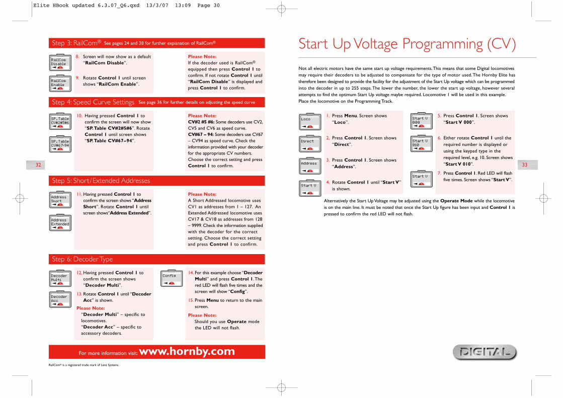
Start Up Voltage Programming (CV)
1. Press Menu. Screen shows“Loco”.
2. Press Control 1. Screen shows“Direct”.
3. Press Control 1. Screen shows“Address”.
4. Rotate Control 1 until “Start V”is shown.
5. Press Control 1. Screen shows“Start V 000”.
6. Either rotate Control 1 until therequired number is displayed orusing the keypad type in therequired level, e.g. 10. Screen shows“Start V 010”.
7. Press Control 1. Red LED will flashfive times. Screen shows “Start V”.
Alternatively the Start Up Voltage may be adjusted using the Operate Mode while the locomotiveis on the main line. It must be noted that once the Start Up figure has been input and Control 1 ispressed to confirm the red LED will not flash.
Not all electric motors have the same start up voltage requirements.This means that some Digital locomotivesmay require their decoders to be adjusted to compensate for the type of motor used.The Hornby Elite hastherefore been designed to provide the facility for the adjustment of the Start Up voltage which can be programmedinto the decoder in up to 255 steps.The lower the number, the lower the start up voltage, however severalattempts to find the optimum Start Up voltage maybe required. Locomotive 1 will be used in this example.Place the locomotive on the Programming Track.
Elite HBook updated 6.3.07_Q6.qxd 13/3/07 13:09 Page 30

35
For more information visit:www.hornby.com
34
Adjusting the Speed Curve
Decide on which CV grouping is best suited to the decoder being programmed. For this example CV#67 – 94will be used.
To Alter CV Settings
1. Press Menu. Screen shows“Loco”.
2. Press Control 1. Screen shows“Direct”.
3. Press Control 1. Screen shows“Address”.
4. Rotate Control 1 until screenshows “CV”.
5. Press Control 1. Screen shows“CV Write”.
6. Press Control 1. Screen shows“CV 0001 W”.
7. Rotate Control 1 until screenshows “CV 0067 W”. PressControl 1 to confirm.
8. Screen shows “CV 0067 W 000”.Rotate Control 1 to choose thevalue of the CV setting (0 – 255)and press to confirm.
9. The red LED will flash confirmingthat the change has been accepted.Should the LED flash eight times thiswill denote that the programminghas not been accepted.Try again.
10. Follow the above procedure workinggradually through the CV settings.
Please Note:It is advisable that before changing thefactory settings that you plot the speedcurve you require on graph paper or asuitable computer programme to avoiduncharacteristic acceleration /deceleration levels.
The speed curve on both the CV#2#5#6 and CV#67-94 are factory set and therefore the acceleration anddeceleration will be consistent, however it is possible to adjust each CV to allow for a different acceleration /deceleration progression providing the decoder being used is suitable for adjustment. Please note that CV#2#5#6provides a more basic acceleration / deceleration progression while the CV#67 – 94 allows for a much finerspeed curve adjustment. Before adjusting any of the Speed Curve CVs it is advisable to produce a graph particularto the locomotive you wish to programme showing how you see the speed curve progressing.This can be achieved by using graph paper and breaking each CV value into 255 segments. Once this has beendrawn plot the speed curve making a note of each of the revised CV settings. Once you have drawn on thegraph the speed curve you require you can then start to install the CVs onto the locomotive decoder via the“CV Write” facility on the Elite. It is worth noting that there are several third party ‘software’ packages whichcan help plot a Speed Curve which may be more preferable than using graph paper.
There may occasions when a decoder CVs may need to be altered.This can be achieved by following thedirections below.
Please Note: Not all decoders have the ability to have their CVs changed. Please refer to the specification sheetsupplied with the decoder which will show which CVs can be adjusted.
For simplicity the following example shows the adjustment of CV4 (Deceleration).
Changing and Reading CVs
1. Press Menu. Screen shows“Loco”.
2. Press Control 1. Screen shows“Direct”.
3. Press Control 1. Screen shows“Address”.
4. Rotate Control 1 until screenshows “CV”.
5. Press Control 1. Screen shows“CV Write”.
6. Press Control 1. Screen shows“CV 0001 W”.
7. Rotate Control 1 until screenshows “CV 0004 W”.
8. Press Control 1 to confirm.Screen shows “CV 0004 W 000”.
9. Rotate Control 1 to adjust thesetting of your choice 1 – 255.Press Control 1 to confirm. RedLED flashes five times. Screenreturns to show “CV”.
10. Press Menu to return to the mainscreen.
Please Note:To read a decoder’s CVs it isimportant that RailCom® is enabledon both the Elite and the decoder.
Note that not all decoders are capableof having their CVs read. Please refer tothe specification sheet supplied withthe decoder.
Elite HBook updated 6.3.07_Q6.qxd 13/3/07 13:09 Page 32

37
For more information visit:www.hornby.com
36
1. Press Menu. Screen shows“Loco”.
2. Press Control 1. Screen shows“Direct”.
3. Rotate Control 1 until screenshows “Operate”.
4. Press Control 1 to confirm.Screen shows “OperateAdr:0003” or the last locomotivenumber operated.
5. Rotate Control 1 until screenshows the number of the locomotivewhose CV you wish to adjust. In thisexample number 10 has beenchosen. Press Control 1 to confirm.
6. Screen shows “Config”. RotateControl 1 until “CV” is shown andpress Control 1 to confirm.
7. Screen shows “CV Write”. PressControl 1 to confirm. Screen shows“CV 0001 W”.
8. Rotate Control 1 until “CV 0003”is shown.
9. Press Control 1 to confirm. Screenshows “CV 0003 W 000”.
10. Rotate Control 1 to adjust thesetting of your choice 1 – 255.
11. Press Control 1 to confirm. Screenshows “CV”.
12. Press Menu to return to the mainscreen.
Please Note:The red LED will not flash.
Some CVs can be altered or read in Operate Mode which means that the locomotive can be left on the mainline.The procedure to do this is as follows.As an example the Acceleration CV (CV3) will be adjusted.
Changing CVs on the Main Line
1. Press Menu. Screen shows“Loco”.
2. Press Control 1. Screen shows“Direct”.
3. Press Control 1. Screen shows“Address”.
4. Rotate Control 1 until screenshows “CV”.
5. Press Control 1. Screen shows“CV Write”.
6. Rotate Control 1 until screenshows “CV Read”.
7. Press Control 1. Screen shows“CV 0001 R”.
8. Rotate Control 1 until thescreen shows “CV 0003 R”.Should the screen show “XXX”this will denote that the CV couldnot be read. If this occurs refer tothe decoder’s specification sheet.
9. Press Control 1.The red LED willlight while the decoder is beingread. Screen shows “CV 0003 R”and the number that CV3 wasprogrammed as.
The following example is for the reading of CV3 (Acceleration) and must be executed with the locomotive on aProgramming Track.
Reading CVs on Programming Track
Changing and Reading CVs (continued)
Please Note:To read CVs it is important thatRailCom® is enabled on both the Eliteand the decoder you wish to read.
Note that not all decoders are capableof having their CVs read. Please refer tothe specification sheet supplied withthe decoder.
Elite HBook updated 6.3.07_Q6.qxd 13/3/07 13:09 Page 34

39
For more information visit:www.hornby.com
38
1. Press Menu. Screen shows“Loco”.
2. Press Control 1. Screen shows“Direct”.
3. Rotate Control 1 until screenshows “Operate”.
4. Press Control 1 to confirm.Screen shows “OperateAdr:0003” or the last locomotivenumber operated.
5. Rotate Control 1 until screenshows the number of the locomotivewhose CV you wish to adjust. Inthis example number 20 has beenchosen. Press Control 1 toconfirm.
6. Screen shows “Config”. RotateControl 1 until “CV” is shownand press Control 1 to confirm.
7. Screen shows “CV Write”.
8. Rotate Control 1 until “CV Read”is shown and press Control 1 toconfirm.
9. Screen shows “CV 0001 R”.
10. Rotate Control 1 until screenshows “CV 0004 R” and pressControl 1 to confirm.
11.The red LED will light while thedecoder is being read. Screen shows“CV 0004 R” and the numberthat CV4 was programmed as.
12. Press Menu to return to the mainscreen.
The following example is for the reading of CV4 (Deceleration) using Operate Mode, i.e. on the main line.
Reading CVs on the Main Line
Changing and Reading CVs (continued)
Please Note:To read CVs it is important thatRailCom® is enabled on both the Eliteand the decoder you wish to read.
Note that not all decoders are capableof having their CVs read. Please refer tothe specification sheet supplied withthe decoder.
Step 1: Allocation of Programming Numbers
1. Press Menu and rotate Control 1until “Acc” is displayed.
2. Press Control 1 to confirm. Screenshows “Direct”.
3. Rotate Control 1 until “Reg” isshown and press Control 1 toconfirm. Screen shows“Address”.
4. Press Control 1 to confirm.Screen shows “Address Write”.
5. Press Control 1 to confirm. Screenshows “Address Adr:0000”.
6. Rotate Control 1 until the addressyou wish to use is displayed. If youare setting up your layout it is bestto start with “1”.
7. Press Control 1 to confirm.Thered LED will flash several times todenote acceptance. (If the LEDflashes eight times or more thenumber has not been accepted.)Screen shows “Address”.
8. Should you wish not to name thepoint / accessory press Menu toreturn the main screen, however ifyou do, follow instructions as shownin Step 2 on page 23.
Accessory Programming (Acc)
Please Note:If using a Hornby Points / AccessoryDecoder it is advisable for consistencythat the first point motor / accessoryis addressed as number 1. Onceaddressed the other three outlets willbe automatically programmed 2, 3, 4.Thereafter all further Hornby accessory/ point decoders should be programmedin consecutive blocks of 4 (i.e. 5, 6, 7, 8).
To programme a Hornby R8216 Accessory/Point Decoder the Register Mode must be selected. For thirdparty Accessory/Point Decoders an alternative programming mode may be required. In this instance please referto the programming information supplied with the third party Accessory/Point Decoder.
Elite HBook updated 6.3.07_Q6.qxd 13/3/07 13:09 Page 36
RailCom® is a registered trade mark of Lenz Systems.
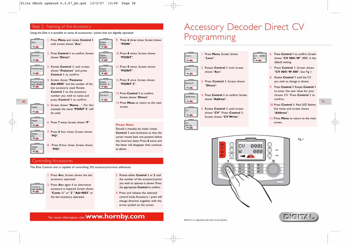
1. Press Menu. Screen shows“Loco”.
2. Rotate Control 1 until screenshows “Acc”.
3. Press Control 1. Screen shows“Direct”.
4. Press Control 1 to confirm. Screenshows “Address”.
5. Rotate Control 1 until screenshows “CV”. Press Control 1.Screen shows “CV Write”.
6. Press Control 1 to confirm. Screenshows “CV 0001 W”. 0001 is thedefault setting.
7. Press Control 1. Screen shows“CV 0001 W 000”. See Fig 1.
8. Rotate Control 1 until the CVyou wish to change is shown.
9. Press Control 1. Rotate Control 1to enter the new value for yourchosen CV. Press Control 1 toconfirm.
10. Press Control 1. Red LED flashesfive times and screen shows“Address”.
11. Press Menu to return to the mainscreen.
Accessory Decoder Direct CVProgramming
Fig 1
41
For more information visit:www.hornby.com
40
Step 2: Naming of the Accessory
Controlling Accessories
1. Press Acc. Screen shows the lastaccessory operated.
2. Press Acc again if an alternativeaccessory is required. Screen shows“Contr. :1” or “2” “Adr:0003” orthe last accessory operated.
3. Rotate either Control 1 or 2 untilthe number of the accessory/pointyou wish to operate is shown. Pressthe appropriate Control to confirm.
4. Press and release the selectedcontrol knob.Accessory / point willchange direction together with thearrow symbol on the screen.
Using the Elite it is possible to name all accessories / points that are digitally operated.
The Elite Control unit is capable of controlling 252 accessory/turnout addresses.
1. Press Menu and rotate Control 1until screen shows “Acc”.
2. Press Control 1 to confirm. Screenshows “Direct”.
3. Rotate Control 1 until screenshows “Features” and pressControl 1 to confirm.
4. Screen shows “FeaturesAdr:0000” and the number of thelast accessory used. RotateControl 1 to the accessorynumber you wish to name andpress Control 1 to confirm.
5. Screen shows “Name _”. For thisexample the name “POINT 5” willbe used.
6. Press 7 twice. Screen shows “P”.
7. Press 6 four times. Screen shows“PO”.
8. Press 4 four times. Screen shows“POI”.
9. Press 6 three times. Screen shows“POIN”.
10. Press 8 twice. Screen shows“POINT”.
11. Press 0 twice. Screen shows“POINT”.
12. Press 5 once. Screen shows“POINT 5”.
13. Press Control 1 to confirm.Screen shows “Direct”.
14. Press Menu to return to the mainscreen.
Please Note:Should a mistake be made rotateControl 1 anti-clockwise so that thecursor moves back one position belowthe incorrect letter. Press 0 twice andthe letter will disappear then continueas above.
Elite HBook updated 6.3.07_Q6.qxd 13/3/07 13:09 Page 38
The Elite has the ability to have the screen instructions shown in four alternative languages other than English.The languages concerned are French, Italian, Spanish and German.
To change from the factory set English screen instructions, the following procedure will be required.
1. Press Menu. Screen shows“Loco”.
2. Rotate Control 1. Screen shows“Unit”.
3. Press Control 1 to confirm. Screenshows “Train 0”. This may varydepending on the last action takenin this mode. However, rotateControl 1 until “Language” isshown. Press Control 1.
4. Screen shows “Language English”.Rotate Control 1 until the languageyou require is shown.Press Control 1 to confirm. Allinstructions will then be shown inthe chosen language.
5. Press Menu to return to the mainscreen.
Language
1. Press Menu. Screen shows“Loco”.
2. Rotate Control 1. Screen shows“Unit”.
3. Press Control 1 to confirm. Screenshows “Train 0”.This may varydepending on the last action takenin this mode. However, rotateControl 1 until “Reset” isdisplayed.
4. Press Control 1 to confirm.Screen shows “Reset Confirm”.
5. If you do not wish to reset pressMenu to return to the main screen.However, if you wish to Reset pressControl 1.The red LED will lightand then start to flash for severalseconds.The screen will then goblank while the unit resets.The screen will return showing“00:00 1 0003”.The unit is nowreset. All information previouslystored has now been deleted.
The Elite unit can be returned to its original factory settings by utilising the Reset function.
Reset
43
For more information visit:www.hornby.com
42
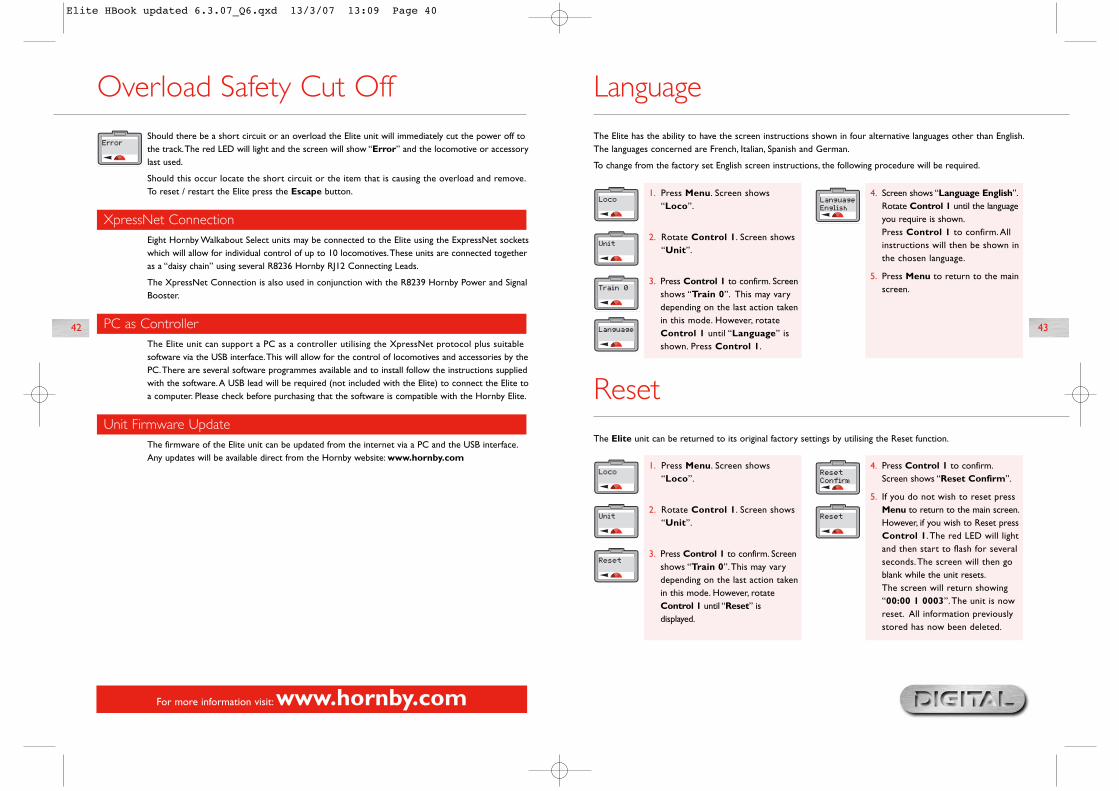
Overload Safety Cut OffShould there be a short circuit or an overload the Elite unit will immediately cut the power off tothe track.The red LED will light and the screen will show “Error” and the locomotive or accessorylast used.
Should this occur locate the short circuit or the item that is causing the overload and remove.To reset / restart the Elite press the Escape button.
PC as ControllerThe Elite unit can support a PC as a controller utilising the XpressNet protocol plus suitablesoftware via the USB interface.This will allow for the control of locomotives and accessories by thePC.There are several software programmes available and to install follow the instructions suppliedwith the software.A USB lead will be required (not included with the Elite) to connect the Elite toa computer. Please check before purchasing that the software is compatible with the Hornby Elite.
Unit Firmware UpdateThe firmware of the Elite unit can be updated from the internet via a PC and the USB interface.Any updates will be available direct from the Hornby website: www.hornby.com
XpressNet ConnectionEight Hornby Walkabout Select units may be connected to the Elite using the ExpressNet socketswhich will allow for individual control of up to 10 locomotives.These units are connected togetheras a “daisy chain” using several R8236 Hornby RJ12 Connecting Leads.
The XpressNet Connection is also used in conjunction with the R8239 Hornby Power and SignalBooster.
Elite HBook updated 6.3.07_Q6.qxd 13/3/07 13:09 Page 40
For more information visit:www.hornby.com
44 45
GlossaryAcceleration DelayThe delay between the locomotive being stationary and reaching the desired speed.
Accessory DecoderAn electronic decoder designed for use in track side accessories such as points or signals.An accessory decoder
is not for use in a locomotive.
AddressA number used to identify a locomotive or accessory that is either equipped or linked to a Decoder.
BusTechnical term for wires that carry electrical signals around a model layout.
Command StationThe Command Station is the ‘brains’ of a DCC system.A Command Station is in essence a micro-computer/
controller that communicates with the decoders that are located either in a locomotive or connected to
accessories.The computer transmits signals to the decoders instructing them what to do, such as accelerate,
decelerate, brake or switch lights on or off.
Configuration Variable (CV)A technical term referring to the operating information of the particular locomotive or accessory that is stored
on the specific decoder.This information will remain “set” until changed using the Command Station.
Consist/ConsistingConsist is an American term, but in the UK it is known by Double or Triple Heading.This is where two or more
locomotives are brought together and function as one.
There are three types of Consisting (1) Basic consisting where the locomotive decoders in the Consist have the
same address. (2) Universal Consisting where the Consist information is stored in the Command Station.
(3) Advanced Consisting is where the Consist information is stored inside the decoder.
DCCDigital Command Control.The application of computer technology to control the movements of locomotives.
Each locomotive is fitted with a decoder (or ‘chip’) which is uniquely programmed and recognises its own
identity and responds only to those control signals which are addressed to it.
DCC also allows a wide range of extras including controllable lighting and on-board sound.The accepted
standards have been laid down by the NMRA (National Model Railroad Association) an American Association.
Programming Definitions As with most innovations the control of model railways using digital signals has developed over theyears. The technical process of programming a locomotive or accessory has also developed andchanged. At present there are in general terms 4 programming systems: Register, Paged,Operate and Direct.
Both Register and Paged were amongst the first systems used and are therefore more suitable foruse with the much older type of decoders.The Operate programme is a newer form of programmingand does offer certain benefits over Direct, the chosen system for the Elite.These benefits are thatcertain programming actions can be accomplished on the Main, i.e. acceleration / decelerationadjustments while the locomotive(s) is / are operating on the circuit.
Direct is the newest and fastest programming mode available at present and it is therefore therecommended mode of programming when using any of the new generation decoders availableincluding those produced by Hornby.
RailCom®
With digital control the controller in simple terms talks or sends commands to each locomotiveindividually. The locomotive responds by basically doing what it is told! RailCom® which is aregistered design and development by Lenz GmBh allows the locomotives to talk to the controller.For example the locomotive can return information to the controller such as speed and details onthe load that is being pulled.
This and much more will be available in time. At the time of writing these instructions the operatingprotocol for RailCom® is still being developed, although like the Elite, products are being introducedonto the market to support RailCom® once the full protocol has been finalised.
It should be noted that the Hornby R8215 Decoder does not support RailCom® therefore ifprogramming this decoder or any other that does not support RailCom®, the RailCom® settingwhile programming a locomotive should be set to “Off” – i.e. “Loco” – “Unit” – “RailCom”– “RailCom Off”.
RailCom® is a registered trade mark of Lenz Systems.
Elite HBook updated 6.3.07_Q6.qxd 13/3/07 13:09 Page 42
47
For more information visit:www.hornby.com
46
Glossary (continued)
Deceleration DelayThe delay of a locomotive slowing down to a standstill.
Feedback (Load Compensating)This allows a locomotive to remain at a constant speed regardless of loads being pulled or incline being
negotiated.
Locomotive DecoderA small PC board which contains a ‘chip’ that stores control information; normally fitted in locomotives.The
Command Station sends coded information to the decoder which can then control the locomotives speed,
direction and any operating functions that the locomotive may have eg lights.
Locomotive Decoders can be fitted to accessories that have a motor as a drive for example the R8131 Hornby
Operating Conveyor or the R8132 Hornby Tipper set.
Occupancy DecoderA unit that can detect the presence of a locomotive on a specific section of track and can provide the appropriateinformation as ‘return’ data.
Power BusCopper strip or wires that can relay power from a Power Booster to the track.
Power Booster/Power StationA Power Booster or Power Station is as the name implies there to provide a boost of power to the track.Thiscan occur if a larger than normal quantity of locomotives are required to be running on the track at the sametime. If the transformer already fitted cannot handle this number then it will be necessary to section the layoutand fit a Power Booster.
This Booster will not only provide more ampage to the drive locomotives but also boost the signals to theDecoders.All Boosters fitted must still be connected to the Power Station.
ProgrammingThe process of assigning an Address to a locomotive or accessory (points or signals).The process of programmingsends a signal containing a numerical identifier to the locomotive being programmed.
Programming TrackA section of track isolated from the main layout purposely for programming locomotives. Programming on aProgramming Track negates the requirement of removing other locomotives from the main layout.
Speed StepsA variable voltage increase used to control motor speeds. Decoders can set the output power for each
speed step.
Stall CurrentStall Current is the maximum current draw in amperes that a locomotive is capable of when stalled. If the
armature of a motor is prevented from turning and the maximum voltage is applied the current draw of the
motor is known as the ‘Stall Current’.
Throttle NotchesDetermines whether a locomotive is controlled with 14, 27, 28 or 128 speed steps.
XpressNetA high-speed communication protocol used for connecting Digital input devices together.
XpressNet (XBUS) Input DevicesDevices using the XpressNet protocol to Control 1 digital layout.
Elite HBook updated 6.3.07_Q6.qxd 13/3/07 13:09 Page 44
4948
For more information visit:www.hornby.com
Safety Notes� This product is not suitable for children under 3 years because of small parts which can present a choking hazard.
Some components have functional sharp points and edges. Handle with care.
� This product is intended for indoor use only.
� This Elite Digital Control system is only to be operated with the Hornby recommended transformers.
� The transformer included is not a toy; it is a “Transformer for Toys”.
� Before use the transformer should be examined for damage to the casing, plug pins and cables. In the event of suchdamage, the Elite unit should not be used until the transformer is replaced with a new Hornby recommended unit.Never attempt to open the unit yourself.
� Before cleaning any part, disconnect the transformer from the mains electricity supply.
� Do not use liquid for cleaning.
� Wires without a connecting means are not to be inserted into outlets.
� The output terminals of the transformers must not be connected directly, or indirectly, to the output of any other mains power supply.
� Please retain these details and the address for future reference.
GuaranteeAll Hornby products are guaranteed against defects in materials and workmanship for a period of 6 months and HornbyDigital electronics for 1 year from the date of purchase.
To qualify for the guarantee, the product must have been used and maintained according to the manufacturersinstructions, and will only be covered when used in conjunction with officially approved Hornby accessories andcomponents.While every possible care and attention has been taken by Hornby to ensure that the product arrives toyou in pristine condition, we cannot accept liability for any subsequent misuse of the product. It is the responsibilityof the consumer to ensure that the product is maintained as per the servicing details provided.
For reliable programming it is important that the track and wheels of all locomotives and wagons used with the EliteDigital system are kept clean. If any defect occurs during the guarantee period, then the item in the first instance shouldbe returned to the place of original purchase.Alternatively, if any such defect occurs during the period of guarantee,then please contact your Hornby Service dealer for advice. Or, the product (or component), may be forwarded toHornby Hobbies Ltd, carefully packed, with a covering letter enclosed giving full details to:
Repairs Department, Hornby Hobbies Ltd,Westwood, Margate, Kent CT9 4JX. UK.
Please include a copy of the original sales document showing the product reference number, date of purchase andfrom where purchased and any other requested information relating to the product. Please obtain a Certificate ofPosting at the time of despatch.
Waste electrical products should not be disposed of with household waste. Please recycle wherefacilities exist. Check with your Local Authority or retailer for recycling advice.
ExclusionsSubject to the exclusions below, the product will be repaired or replaced free of charge, if the problem is found tobe due to either workmanship or materials.The repair/replacement will be provided as promptly as possible withoutsignificant inconvenience to the consumer:
� The fault has been caused or is attributable to mis-use, negligent use or used contrary to the manufacturersrecommendations.
� Accidental physical damage.
This guarantee is valid for products purchased in the United Kingdom and is in addition to, and does not diminish,your statutory rights. For further advice about your statutory rights contact your local authority Trading StandardsDepartment or Citizens Advice Bureau.
This warranty only covers Hornby manufactured items. Please retain these details and address for future reference.
Locomotive will not runCheck that all the wiring is correctly connected to the track and Controller and that the transformer is pluggedinto the wall socket and is switched on.
Ensure that the correct loco address is displayed on the LCD.
Check that the “STOP” button has not been pressed accidentally.
The trains do not run smoothlyThe locomotives require a clean track so that they can receive their information from the Elite, thereforeensure that the track is clean. Use an R8087 Track Rubber to remove dirt from the track and wheels of thelocomotive. Do not use any other abrasive material as this will permanently damage the track and/or wheels.
All locomotives move off togetherMake sure that a locomotive has not been given a new address while other locomotives have been on the sametrack.To avoid this it is advisable to use a Programming Track to add new addresses to locomotives and HornbyPoint/Accessory Decoders. See page 22
All locomotives appear to have the same Acceleration/Deceleration levelsMake sure that a locomotive has not been programmed using Direct, Paged or Register modes with accelerationand deceleration levels while other locomotives have been on the same track.To avoid this happening it isadvisable to use a Programming Track to add new addresses to locomotives and Hornby Point / AccessoryDecoders. See page 22.To programme acceleration and deceleration on the main track use the Operate mode.
System keeps cutting outCheck that there is no metal across the track that may be causing a short circuit.Also check that the system isnot being overloaded by too many locomotives trying to run at the same time.
The 4 amp transformer included with the Elite should within reason be capable of providing enough power torun nine locomotives. If in doubt consult your local dealer or the Hornby DCC Helpline.
Trouble Shooting
Do not connect any other controller to the Hornby Elite other than a Hornby Walkabout Select.Whenusing a Select with the Elite ensure that the Select is not connected directly to a mains transformer.
Do not run coreless motored locomotives on a DCC layout without them having a decoder fitted.
If in doubt please contact Hornby or your local dealer for advice.Tel. +44 (0)1843 233525 Email. [email protected] Web. http://www.hornby.comHornby PLC,Westwood Industrial Estate, Margate, Kent CT9 4JX.
Elite HBook updated 6.3.07_Q6.qxd 13/3/07 13:09 Page 46
50
For more information visit:www.hornby.com
Notes LocomotiveAddress
Elite HBook updated 6.3.07_Q6.qxd 13/3/07 13:09 Page 48