horizontalflowabilityreportn°21, version 29803
TRANSCRIPT
HORIZONTAL –Report N° 21 (WP7 Part A)
Draft
Physical Properties
- Flowability -
Desk study
P. Battistoni*, L. Spinosa ***, E. Carniani *, K. Wichmann**, C. Thormählen**, E. Pasqualini*, E. Fratalocchi*,
*Contractor: Polytechnic University of Marche Region, Italy, Email [email protected] Cooperation: ** Technical University Hamburg-Harburg (TUHH), Germany, *** CNR c/o Commissariat for Env. Emerg. in Puglia Region, Italy

2 HORIZONTAL – Report n°21
Acknowledgement
This work has been carried out with financial support from the following EU Member States:
UK, Germany, France, Italy, Spain, Nordic countries, Netherlands, Denmark, Austria, EU DG
XI and JRC, Ispra.

HORIZONTAL – Report n° 21 3
CONTENTS
LIST OF TABLES ....................................................................................................................................................5
SUMMARY..................................................................................................................................................................6
1. INTRODUCTION ............................................................................................................................................7 1.1 THE HORIZONTAL PROJECT ...................................................................................................................... 7 1.2 THE WORK PACKAGE 7............................................................................................................................. 7 1.3 DESK STUDIES SUBJECT............................................................................................................................. 8 1.4 EVALUATION OF NEEDS FOR CONTROL OF OPERATION AND MATERIAL CHARACTERISTICS.......... 9 1.5 EVALUATION OF NEEDS FOR CONTROL OF OPERATION......................................................................... 9
1.5.1 Material characteristics....................................................................................................................10 1.5.1.1 Sewage sludge ............................................................................................................................. 10 1.5.1.2 Water work sludge ....................................................................................................................... 11 1.5.1.3 Treated bio-waste......................................................................................................................... 13 1.5.1.4 Soil ............................................................................................................................................... 15
1.6 SEARCH FOR EXISTING STANDARDS AND METHODS........................................................................... 16 1.7 BASIC INFORMATION............................................................................................................................... 17
1.7.1 Flowability and rheology..................................................................................................................17 1.7.2 Rheology and sludge management..................................................................................................17 1.7.3 Rheological measurements ...............................................................................................................18
2. EXISTING STANDARDS OR DRAFT STANDARDS .......................................................................19 2.1 FLOWABILITY........................................................................................................................................... 19 2.2 SOLIDITY................................................................................................................................................... 19 2.3 THIXOTROPIC BEHAVIOUR...................................................................................................................... 20 2.4 PILING BEHAVIOUR.................................................................................................................................. 20
3. EVALUATION OF DRAFTING A HORIZONTAL STANDARD ..................................................21 3.1 CAPILLARY VISCOMETERS...................................................................................................................... 21
3.1.1 Standards analysed............................................................................................................................21 3.1.2 Laboratory or field test feasibility...................................................................................................24 3.1.3 Apparatus.............................................................................................................................................24 3.1.4 What is measured and how...............................................................................................................25 3.1.5 Material to be examined....................................................................................................................26 3.1.6 Feasibility of the methods to the materials for Horizontal project............................................26
3.2 PENETROMETER....................................................................................................................................... 26 3.2.1 Standards analysed............................................................................................................................27 3.2.2 Laboratory or field test feasibility...................................................................................................29 3.2.3 Apparatus.............................................................................................................................................30 3.2.4 What is measured and how...............................................................................................................31 3.2.5 Material to be examined....................................................................................................................32 3.2.6 Feasibility of the methods to the materials for Horizontal project............................................33
3.3 ROTATIONAL VISCOMETERS................................................................................................................... 33 3.3.1 Standards analysed............................................................................................................................33 3.3.2 Laboratory or field test feasibility...................................................................................................36 3.3.3 Apparatus.............................................................................................................................................36 3.3.4 What is measured and how...............................................................................................................39 3.3.5 Material to be examined....................................................................................................................40 3.3.6 Feasibility of the methods to the materials for Horizontal project............................................40
3.4 “FLOW” APPARATUS................................................................................................................................ 41 3.4.1 Standards analysed............................................................................................................................41 3.4.2 Laboratory or field test feasibility...................................................................................................46 3.4.3 Apparatus.............................................................................................................................................46 3.4.4 What is measured and how...............................................................................................................49 3.4.5 Material to be examined....................................................................................................................49 3.4.6 Feasibility of the methods to the materials for Horizontal project............................................50

4 HORIZONTAL – Report n°21
4. CRITICAL POINT AND RECOMMENDATIONS ............................................................................ 51 4.1 FLOWABILITY............................................................................................................................................51
4.1.1 Comparison (discussion: pro/contra)............................................................................................ 51 4.1.2 Recommendations.............................................................................................................................. 52
4.1.2.1 Laboratory reference ....................................................................................................................52 4.1.2.2 Field test.......................................................................................................................................52
4.2 SUMMARY OF RECOMMENDED METHODS.............................................................................................53 4.3 RESEARCH NEEDS.....................................................................................................................................53
4.3.1 Basics of methods............................................................................................................................... 53 4.3.2 Applicability of methods to Horizontal materials........................................................................ 53 4.3.3 Questions to be answered (precision, repeatability, reliability, etc.) ....................................... 54 4.3.4 Route, how to answer them.............................................................................................................. 54 4.3.5 Steps to be taken................................................................................................................................. 54
4.4 CONTACTS WITH CEN/TC'S/WG' S........................................................................................................54 4.4.1 Actions................................................................................................................................................. 54 4.4.2 Official meetings................................................................................................................................ 55
5. DRAFT STANDARD (CEN TEMPLATE)............................................................................................. 55 5.1 FLOWABILITY............................................................................................................................................55
5.1.1 Laboratory reference......................................................................................................................... 55 5.1.1.1 Method 1......................................................................................................................................55
5.1.2 Field test.............................................................................................................................................. 55 5.1.2.1 Method 1......................................................................................................................................55 5.1.2.2 Method 2......................................................................................................................................55 5.1.2.3 Method 3......................................................................................................................................55
REFERENCES ......................................................................................................................................................... 56
ANNEX 1 .................................................................................................................................................................... 58
ANNEX 2 .................................................................................................................................................................... 58
ANNEX 3 .................................................................................................................................................................... 58
ANNEX 4 .................................................................................................................................................................... 58
ANNEX 5 .................................................................................................................................................................... 58
ANNEX 6 .................................................................................................................................................................... 58
ANNEX 7 .................................................................................................................................................................... 58

HORIZONTAL – Report n° 21 5
LIST OF TABLES
Table 1: Particle size distribution of sewage sludges .............................................................10 Table 2: Rheological properties of sewage sludges................................................................11 Table 3: Determination of the composition of sludge.............................................................12 Table 4: Particle size distribution of OFMSW.......................................................................14 Table 5: Rheological properties of OFMSW aerobically or anaerobically treated....................14 Table 6 : Grain size of soils according to different classification systems................................16 Table 7: Importance of the sludge physical states in its management. .....................................18 Table 8: Standards examined for capillary viscosimeters .......................................................23 Table 9: Standards examined for penetrometer .....................................................................29 Table 10: Standards examined for rotational viscosimeters....................................................36 Torsion strain oscillating rheo Table 11 Standards examined for rotational viscosimeters........37 Table 12: Standards examined for flow apparatus .................................................................46 Table 13 Overview of recommendations ..............................................................................53
LIST OF FIGURES
Figure 1: Correlation between shearing strength and dry solid method [9] ..............................11 Figure 2: Comparison dry solid contents vs. laboratory vane shear strength [12] .....................13 Figure 3- Rheogram types ...................................................................................................17 Figure 4: Gravity flow capillary viscometer (Modified Ubbelohde type) ................................25 Figure 5: Vicat apparatus ....................................................................................................30 Figure 6: Laboratory soil penetrometer................................................................................31 Figure 7: Magnesium Cone Penetrometer.............................................................................31 Figure 8: Brookfield viscometer..........................................................................................37 Figure 9: Coaxial cylinder viscometer..................................................................................38 Figure 10: Stormer viscometer.............................................................................................38 Figure 11: Flow cone (dimensions in mm) ............................................................................47 Figure 12: Hollow perforated tube for flow tests ...................................................................48 Figure 13: Tube extrusion viscometer (kasumeter)................................................................48

6 HORIZONTAL – Report n°21
SUMMARY
The “Horizontal” project has the objective to develop horizontal and harmonised European standards in the fields of sludge, soil and treated bio-waste to facilitate regulation of these major streams in the multiple decisions related to different uses and disposal governed by EU Directives. The Horizontal Project includes the Work Package 7 “Mechanical properties” consisting in the development of Desk Studies on physical consistency, because it is recognized that this property is very important for the characterization of sludge, since it affects almost all treatment, utilization and disposal operations, such as storage, pumping, transportation, handling, land-spreading, dewatering, drying and land-filling. The importance of the physical consistency is also true for the characterization of treated bio-waste and soil. Also handling and utilization of many other materials, such as cement and asphalt, are strictly depending on their physical consistency. The needs for operation and also materia l characteristics are described. The first action carried out is consisted in searching for existing standards to be possibly used or adapted for utilisation in the specific field of consistency evaluation. The complete list of standards is reported in Annex 1, divided into four parameter groups: solidity, flowability, thixotropy and piling from which it can be seen that more than 250 standards and non standardized methods are potentially applicable to consistency evaluation. On the basis of the selected list for further consideration the methods for the determination of flowability of sludge, treated bio-waste and soil, have been divided into four groups, according to the instruments used for measuring: capillary viscometers, penetrometer, rotational viscometers and flow apparatus. For each group it was evaluated the laboratory or field test feasibility. Apparatuses of the measuring procedure and existing application to different materials were described. On these basis the applicability of the described methods to the materials for the Horizontal project was evaluated and documented in the list of analized standards. The recommended methods for further investigation can be divided in two groups. The first group includes methods and instruments suitable to characterise Horizontal materials in the field. The second group includes methods and instruments suitable to characterise Horizontal materials in laboratory scale . The laboratory apparatus is the coaxial cylinder viscometer while field apparatus are flow cone, magnesium penetration cone and extrusion tube viscometer. They must be tested and optimized to adapt design and part dimensions to Horizontal material in a future experimental activity. For the research needs first the basics of methods are explicated and o the applicability of methods to Horizontal materials is clarified. The questions to be answered (precision, repeatability, reliability, etc.), the route how to answer them and finally the steps to be taken are defined since they are important for following procedures within the Horizontal project. The results of the circulation within the consulting CEN/TC’s/WG1’s/TG’s – Committee’s are documented by means of listed actions, received comments, and official meetings ( four WP7 meetings , two CEN/TC308/WG1 meetings , one CEN/TC308/WG1/TG3, one CEN/TC292/WG2). In the Horizontal Report N° 21 a total of 4 proposals for draft standards are given, whereby one laboratory method and three field tests exists.

HORIZONTAL – Report n° 21 7
1. INTRODUCTION
1.1 The Horizontal project
The revision of the sewage Sludge Directive 86/278/EEC, the upcoming Directive on the biological treatment of biodegradable waste and the Soil Monitoring Directive call for standards on sampling, hygienic and biological parameters, methods for inorganic and organic contaminants, and for mechanical properties of these materials. In addition, when materials cannot be utilized, land-filling becomes important, in which case leaching becomes an issue as stipulated by the Council Directive 1999/31/EC on the landfill of waste. More recently, a Council Directive establishing criteria and procedures for the acceptance of waste at landfills, pursuant to Article 16 and Annex II of mentioned Directive on waste landfilling was issued (16/12/02). The “Horizontal” project has the objective to develop horizontal and harmonised European standards in the fields of sludge, treated bio-waste and soil to facilitate regulation of these major streams in the multiple decisions related to different uses and disposal governed by EU Directives. Part of the work to be carried out will focus on co-normative work with an emphasis on Horizontal standardization starting from existing standards developed for the same parameter in the fields of sludge, treated bio-waste and soil. Another part of the work will focus on pre-normative research required to develop standards lacking at this point and needed in the next revision of the regulations in these fields.
1.2 The Work Package 7
The Horizontal Project includes the Work Package 7 “Mechanical properties” consisting in the development of Desk Studies on physical consistency, because it is recognized that this property is very important for the characterization of sludge, since it affects almost all treatment, utilization and disposal operations, such as storage, pumping, transportation, handling, land-spreading, dewatering, drying, land-filling. In fact, the selection of the most suitable equipment and procedure for land application, storage and transportation of sludge, is strongly connected to its consistency. Similarly, compacting sludge in a landfill or forming a pile in composting is depending on sludge shear strength rather than on its solids concentration . In particular, with reference to the regulations requirements, according to the Sludge Directive 278/86, agricultural reused sludge must have agronomic interest, be healthy and easily usable, i.e. easily stored, transported, handled, and spread. In Council Directive 1999/31/EC (Landfill Directive), Article 2 (q) gives a definition of “liquid waste”, and Article 5 (3.a) does not allow a liquid waste to be land-filled, but a standardized method for this evaluation has to be developed yet. Further, Annex II (2. General principles) requires that “The composition, ... and general properties of a waste to be land-filled must be known as precisely as possible”, and Annex I (6. Stability) is referring to “... ensure stability of the mass of waste ... particularly in respect of avoidance of slippage”, so the shear strength and piling behaviour must be known. Article 2 (h) says, that “treatment means ... processes ... in order to … facilitate its handling”. Finally, Article 11 (1.b) asks for: “ – visual inspection of the waste at the entrance and at the point of deposit and, as appropriate, verification of conformity with the description provided in the document submitted by the holder”, so simple and easy tests to be carried out on the field and followed by the operator must be defined.

8 HORIZONTAL – Report n°21
Further, the Council Directive establishing criteria and procedures for the acceptance of waste at landfills, pursuant to Article 16 and Annex II of mentioned Directive on waste landfilling included “consistency” among the basic parameters to be evaluated for waste characterization before land-filling; for specific cases it is also demanded, that EU Member States must set criteria to ensure a sufficient physical stability and bearing capacity of waste. It is also to be pointed out that in many analytical methods for sludge characterization (e.g. pH, dry matter, leachability, etc.) different procedures are indicated depending on whether the sample to be examined is liquid or not, is solid or not, but no procedures are given for evaluating such properties. The importance of the physical consistency is also true for the characterization of treated bio-waste and soil. Also handling and utilization of many other materials, such as cement and asphalt, are strictly depending on their physical consistency. For WP7 two desk studies were performed - n° 21 for the parameter “Flowability” and n° 22 for parameter “Solidity”, “Thixotropic behaviour” and “Piling behaviour”. The work was coordinated in WP7 and done in cooperation of the involved teams. Therefore, the reports n° 21 and n° 22 contain some chapters (from 1.1 to 1.5, and 2) and the lists of standards and non standardized methods (Annex 1) in common.
1.3 Desk studies subject
The Task Group 3 (TG3) of CEN/TC308/WG1 defined 3 physical states for sludge (CEN/TC308/WG1/TG3, 2000): a) Liquid: sludge flowing under the effect of gravity or pressure below a certain threshold. b) Paste-like: sludge capable of continuous flow under the effect of pressure above a certain
threshold and having a shear resistance below a certain threshold. c) Solid: sludge having a shear resistance above a certain threshold. This firstly involves the necessity to set up methods to define the boundary area between liquid and paste-like behaviours (limit of flowability) and that between solid and paste-like (limit of solidity ). Further, the thixotropic behaviour from “the solid to the liquid state and vice versa” must be evaluated, together with the piling behaviour referred both to “compaction and physical stability”. Also the CEN/TC292/WG2, in the method prEN 12457 for the characterisation of waste included in Annex B (Informative) the description of a test for determining whether waste is in the liquid state (CEN/TC292/WG2, 2002). Unless the methods to be developed are partly known and used in other technology fields, e.g. soil mechanics, materials for construction works (concrete, suspensions), etc., widely accepted methodologies for the evaluation of above properties, able to give comparable and reliable results, are not available yet. It therefore follows the necessity to define simple and reliable measurement procedures to be applied in the field, together with those to be used as reference in laboratory. Standardisation procedures for Horizontal material examination will consist of :
o sampling, transport, preservation, storage, o pre-treatment, o measurement and evaluation of results.

HORIZONTAL – Report n° 21 9
1.4 Evaluation of needs for control of operation and material
characteristics
1.5 Evaluation of needs for control of operation
The purpose of using characterisation standards is to control and ascertain the material amenability to handling and different operations. Material considered are:
o sewage sludge, o water works sludges, o treated bio-waste and o soils.
For handling and operation of these materials many parameters should have to be known; they include homogeneity, particles sizes and shape, solids (total, suspended, volatile) that, if available, could define the range of variation of variable considered (i.e. viscosity, etc.). The parameters flowability is an overall parameters taking into account all above materia l properties or characteristics. In particular, the flowability evaluation for sludges, including wastewater, waterworks and similar sludges, is of fundamental importance in many operations such as pumping, transportation, storage, dewatering, stabilisation, spreading, etc.. also considering the possible formation from a gel to a liquid and vice versa. Similarly, for treated bio-waste, including the shredded organic fraction of municipal solid waste (OFMSW), in operations such as handling, digestion, reuse, etc. the measure of the parameter flowability has to be considered. Finally, for fine grained soils, the water content (and therefore consistency and flowability) have always been considered an important indication of their mechanical properties. Moreover, in case of soil slurries it is very important to verify flowability as a measurement of their workability and time of setting. The solidity is also a parameter, which concerns all the material properties or characteristics mentioned above. The determination of this parameter is getting more important for handling of solid materials like dewatered sludge, other treated bio-waste – e.g. in terms of pieces (compost) – and soil, where the grain size distribution and water content have to be considered, during operations like pumping, transportation, storage, etc.
The measurement of thixotropic behaviour for solids materials is especially for dewatered sludges like sewage, water works and related sludges relevant. By dewatering and storage the sludge will become solid. During operation such as transportation the sludge is getting due to the vibration in a liquid state. The piling behaviour evaluation is for dewatered sludge particular treated by-waste and soil of importance.
The determination of the piling angle is a useful instrument to characterize the storage properties and calculate the space, which is needed for e.g. storage and transportation of the above materials. Together with the thixotropic behaviour the piling behaviour referred to the compaction and stability.
However, the development of reliable measurement procedures of all parameters is not a simple matter, just because measurements are influenced by above listed properties or characteristics. This means that those factors must be considered with great attention and methods defined by avoiding any negative interference of them on the measure. For this reason, it is first necessary to select, if any, the most adapted standards or non standardized methods applicable to sludges, treated bio-waste and soil, or to develop a new one, and then to carry out parallel tests to evaluate how they are affected by the other specific characteristics.

10 HORIZONTAL – Report n°21
In addition, these aspects require to be investigated for both laboratory methods, to be adopted as a reference, and simple tests to be applied in the field.
1.5.1 Material characteristics
1.5.1.1 Sewage sludge Sewage sludge can be produced from several process (primary sedimentation, activated sludge process, aerobic or anaerobic digestion, etc…). Their solid content cover a wide range from minus 1 to 30%, while total volatile solids content on dry matter can vary from 75% to 45%. The presence of coarse particles is strongly related to the sieve adopted in head-works or external material used in some processes (anaerobic co-digestion, etc.). Sewage sludge cover a wide range of physical state from liquid to solid. Bibliography does not offer a characterization of particle size distribution of sewage sludge, a wide range of these characteristics is forecasting in relation to the process adopted (opening of sieves, etc..) and different type of sewage sludge treated. Some indications are found in Table 1 [1]).
TS basis % cumulative retained w.w.
TVS basis % cumulative retained
w.w.
Material
Process
5 mm 2 mm 0.84 mm 5 mm 2 mm 0.84 mm
Sewage sludges WTS
Aerobic process
0
3,7
9,4
0
4,7
8,4
Mixed primary sludges ADS
Mesophilic anaerobic digestion
0 10,5 18,5 0 15,5 30,5
Table 1: Particle size distribution of sewage sludges
Each kind of sludge was analysed for its particle size distribution by wet sieving, using three sieves with openings of 5, 2 and 0.82 mm. According to these data the samples can be divided into four conventional classes: coarse (>5 mm), medium (from 5 to 2 mm), medium-fine (from 2 mm to 0.84 mm) and fine (<0.84 mm). It can be noted that the sewage sludges have no coarse particles but a different percentage of medium and fine particles. The most diffuse sludge characterization is that rheological, beside CST – capillary suction time, R specific resistance to filtration etc.. Rheological parameters (yield stress, viscosity and thixotropy) were originally applied to calculation of the head losses in sludge pumping operations, recently it has been shown that they can affect filtration, thickening [2], pumping [3,4] and constitute useful on line control parameters for sludge conditioning and dewatering [5,6,7]. Rheological measurements of sewage sludges have been performed using commercial rotational viscometer . The rheological properties normally determined by using the Bingham plastic model are the yield stress (YS) (that is the stress required to start the material flowing) the plastic viscosity (that is the internal resistance to flow under defined shear rate). The thixotropy, determined by the hysteresis area, is only sometimes observed (Table 2) [8]. Mechanical properties of sewage sludge in solid state were studied with the aim to define the feasibility of landfill disposal; a correlation between shear strength and dry solid matter for sewage sludge was done using a Vane apparatus ( Figure 1 ) [9], sludges are suitable for land-filling if their shear strength is of 10 kN/m2 at least (limit valid in Italy).

HORIZONTAL – Report n° 21 11
Sludge Process TS range TVS/TS YS Plastic viscosity
% Pa mPa.s Mixed 3.0-14 0.52 1.90-185 30-630 Primary 7.0-16 0.43 1.0-49 20-320 Activated 3.0-9 0,73 5.0-214 70-1110 Mixe Sludges Aerobically
stabilized 4.0-10 0.53 0.07-58 10-410
Mixed Sludges Anaerobically digested
4.0-9 0.59 1.0-112 20-390
Mixed sludges Mesophilic anaerobic digestion
3.5-5.0 0.5-0.6 0.4-1.6 8.0-24
Mixed sludges Thermophilic anaerobic digestion
3.5-5.0 0.5-0.6 0.1-0.5 11.0-17
Table 2: Rheological properties of sewage sludges
Figure 1: Correlation between shearing strength and dry solid method [9]
1.5.1.2 Water work sludge In general sludges are defined as capable of flowing solid-water suspensions after sedimentation, flotation or thixotropy of solids contained water, in which un-dissolved components are accumulated. Dewatered sludges are sludges, which were dewatered by natural or mechanical treatments until they are no longer able to flow.

12 HORIZONTAL – Report n°21
Sludges from water treatment contain several phases differing by their physical state and/or chemical nature. The space ordering of these phases, as well as the physical-chemical interactions between them, give to sludges their cohesion. A too low cohesion of sludges and/or its high fluctuation in the time commonly generates handling (shovelling- and spreading- ability) and storing difficulties.
Parameter Fraction [g/kg DS] (Fictive value)
Conversion in: Fraction [g/kg DS]
Acid insoluble (= HClins.)
40 Insoluble components (e.g. sand, activated carbon)
40
TOC 30 Total organ. content (Factor: 2)
60
Mn 20 MnO2
(Factor: 1.58) 31.6
Mg 5 Mn(OH)2 (Factor: 2.,4)
12.0
Al 20 Al2O3 x H2O (Factor: 2.22)
44.4
SO4 5 CaSO4 (Factor: 1.42)
7.1 (Ca: 2.1)
CO3 (= TIC) 80 CaSO3 (Factor: 1.67)
138.6 (Ca: 57.6)
Ca –total- 65 - Residual-Ca 5.3 Ca3(PO4)2
(Factor: 2.58) 13.7
(PO4: 8.4) PO4 –total- 10 -
Residual-PO4 1.6 Fe(PO4) (Factor: 1.59)
2.5 (Fe: 0.94)
Fe –total- 415,7 - Residual-Fe 414.8 Fe2O3 x 1,5 H2O
(Factor: 1.67) 692.6
Total 1042.5 Table 3: Determination of the composition of sludge An orderly utilisation and disposal of waterworks sludges needs the control of the mechanical properties in order to ensure a quality that is demanded for storage, transport and handling. The mechanical measurements are to be seen and done in connection with other measurements that have been or will be standardised. There are to be mentioned methods for chemical and physical parameters (chemical elements, dry solids, loss on ignit ion, pH-value) and operational methods (capillary suction time CST, specific filtration resistance). The different composition of waterworks sludges with inorganic (Fe, Ca, Al etc.) and organic (Algae, humid substances, powdered activated carbon etc.) substances depending on the source of raw water and water treatment processes must be considered. An inquiry from Wichmann et al (2002) [10] showed, that the waterworks sludges of different types in Germany amounted in 1998 to ca. 181.000 t DS (Lime sludge 40%, Iron sludge 14%, Fe-/Al-Flocculation sludge 13% and other 33%). The composition of the sludge can be determined using ten different parameters as shown in Table 3 [11]

HORIZONTAL – Report n° 21 13
Figure 2: Comparison dry solid contents vs. laboratory vane shear strength [12] The range of 0.2 to 80 % dry solid contents of waterworks sludges to be utilized is quiet wide, so that several different mechanical properties have to be measured. Possible measuring methods are coming mainly from the soil mechanical or Rheological working fields. There are only few data on mechanical properties of waterworks sludges published. In Figure 2 after Mc Tigue et al. 1990 [12] e.g. the result of 72 measurement data of different waterworks sludge types and dewatering processes are shown. A laboratory vane shear apparatus was used. The vertical line marks the dry solids concentration of 35 % that was given from LAGA (1979) [13]) as a minimum value for disposal of wastes in landfills. Sludges with more than 35 % DS were than be considered to be qualified for landfilling. The horizontal line marks the minimum value of 25 kN/m2 for the vane shear strength that is now demanded from new regulations in the TA Siedlungsabfall (1993, [14]). Approximately 90 % of the waterworks sludges tested after mechanical dewatering could not fulfil the required minimum value.
1.5.1.3 Treated bio-waste Organic fraction of municipal solid waste (OFMSW) is utilized for anaerobic and composting treatment. Anaerobic digestion or co-digestion with sewage sludges is a well known process where rheological parameters have been studied to process control. The OFMSW was analysed for its particle size distribution by wet sieving, using three sieves with openings of 5, 2 and 0.82 mm (Table 4). According to these data the samples can be divided into four conventional classes: coarse (>5 mm), medium (from 5 to 2 mm), medium-fine (from 2 mm to 0.84 mm) and fine (<0.84 mm). The fresh mechanical sorted OFMSW show up to 18 and 24% of particles greater than fines for TS and TVS, respectively. The coarse particles are mainly extraneous materials (plastics, baggage, etc.), which have no influence on digester fluid-dynamic [15,16].
0
5
10
15
20
25
30
35
40
0 5 10 15 20 25 30 35 40 45 50 55 60
Dry Solid [% w/w]
Van
e S
hear
Str
engt
h [k
N/m
2 ]

14 HORIZONTAL – Report n°21
TS basis % cumulative retained w.w.
TVS basis % cumulative retained
w.w.
Material
Process
5 mm 2 mm 0.84 mm 5 mm 2 mm 0.84 mm
Fresh mechanically sorted OFMSW
Mesophilic anaerobic digestion
8,2 11,1 18,3 6,7 21 23,5
Pre-composted mechanically sorted OFMSW
Mesophilic anaerobic digestion
19,7 26,1
Blend of source sorted and mechanically sorted OFMSW
Mesophilic anaerobic digestion
6,6 11,5 18,3 12,7 16,8 24,2
Table 4: Particle size distribution of OFMSW
Rheological measurements of OFMSW aerobically and anaerobically treated have been performed using commercial rotational viscometer. The rheological properties normally determined by using the Bingham plastic model are the yield stress (YS) (that is the stress required to start the material flowing) and the plastic viscosity (that is the internal resistance to flow under defined shear rate). The thixotropy, determined by the hysteresis area, is only sometimes observed (Table 5) [15,16].
Sludge Process TS range TVS/TS YS Plastic viscosity
Thixotropy
% Pa mPa.s Pa/s OFMSW mechanically sorted and pre-composted
Thermophilic anaerobic digestion
4.8-32.7 0.43-0.49 0.4-63 9-840
Fresh OFMSW mechanically sorted
Thermophilic anaerobic digestion
6.8-25.2 0.47-0.50 0.1-102 17-1660
OFMSW mechanically sorted enriched with source sorted fraction
Thermophilic anaerobic digestion
5.8-35.1 0.46-0.56 0.2-61 6-560
OFMSW Anaerobically digested under mesophilic and semi-dry conditions
4.4-18 0.52 0.25-1.2 8.0-54 12-125
OFMSW Anaerobically digested under thermophilic and semi-dry conditions
5.0-32.7 0.48 0.26-37.7 10-420 36-161
Table 5: Rheological properties of OFMSW aerobically or anaerobically treated

HORIZONTAL – Report n° 21 15
1.5.1.4 Soil Soils are particulate systems and can cover a wide range of physical state from liquid to solid, depending mainly on the size and mineralogy of the particles and on the water content. In particular, soils are divided into coarse grained soils and fine grained soils. The surface of the particles has a negative electrical charge, whose intensity depends on the soil mineral. This surface forces exist in addition to the volume forces of the particles and in fine grained soils they play a dominant role in the mechanical and rheological behaviour. The surface forces strongly depend on the water content and more in general on the chemical composition of the interstitial fluid.
For this reason, it is very important to set up standards that can define different physical states considering not only the water content but also the chemical composition of the pore fluid. The classification of a granular soil is completely defined by the grain distribution curve (Table 6), the shape of particle and its specific volume. Whereas the procedure for particle size analysis is well defined and easy to perform (by a simple sieve analysis), a procedure for characterising the particle shape is not available and it should be defined as the particle shape strongly influence the mechanical behaviour of these type of soils.
The behaviour of cohesive soils depends on its mineral composition, the water content, the degree of saturation and its structure. A fine grained soil can be in a liquid, plastic, semi-solid or solid state, depending on its water content and this physical state is called consistency. The upper and lower limits of water content within which a clay element exhibits plastic behaviour are defined as liquid limit and plastic limit. The procedure is standardised (ASTM D 4318) but it is recognised to be strongly affected by the operator experience. Typical values of liquid limit for natural fine grained soils ranges from 40% up to 90% of water content and the plastic limit from 10%-50%. Many correlations have been proposed relating the mechanical characteristics of cohesive soils and the consistency limit, each of them is valid for the specific type of soil for which it was verified.

16 HORIZONTAL – Report n°21
Table 6 : Grain size of soils according to different classification systems.
1.6 Search for existing standards and methods
The first action carried out is consisted in searching for existing standards to be possibly used or adapted for utilisation in the specific field of consistency evaluation.
To this purpose, the following standardisation organisations were contacted: • ISO at www.iso.ch • ASTM at www.astm.org • CEN at www.cenorm.be • UNI at www.uni.com • DIN at www.beuth.de • AFNOR at www.afnor.fr/portail.asp • BSI at www.bsi.org.uk • ASAE at webstore.ansi.org Other information was obtained through personal contacts with experts in the field. In addition, to obtain selected information, the following keywords were used for research in each web site: consistency, viscosity, flowability, shearing, sludge, soil, physical properties, flow properties, suspensions, compactibility. The different materials resulted from the research were resins, plastic, lubricant, cement, asphalts/bitumens, soil, solid waste, etc.. The complete list of standards is reported in Annex 1, divided into four keyword groups: solidity, flowability, thixotropy and piling; from which it can be seen that more than 250 standards and non standardized methods are potentially applicable to consistency evaluation.

HORIZONTAL – Report n° 21 17
1.7 Basic information
1.7.1 Flowability and rheology
Flowability is the state in which a material is able to “flow”, i.e. it behaves as a liquid. This characteristics is, therefore, strictly connected to rheological properties, as rheology is the science of deformation studying the relationship between shear stress (internal stress) and shear rate (velocity of deformation) which can be depicted in a rheogram. The rheological behaviour of very thin sludges is Newtonian, like water, i.e. the viscosity is independent of the flow rate (shear rate) and no initial resistance is shown if a force is applied at rest (yield stress). This is shown in Figure 1, as T=µD, where T is the shear stress, D the shear rate and µ the viscosity. Instead, the behaviour of more concentrated suspensions is described as non-Newtonian: they may exhibit a yield stress and the viscosity may vary with the shear rate. As shown in Figure 1, many models are applicable: a general equation is T=T0+µDn, where T0 is the yield stress, µ the plastic viscosity or fluid consistency index, and n the fluid behaviour index). The Bingham plastic model, with n=1, so no curvature of the rheogram is exhibited, should seem to be preferable, as it allows to define a unique viscosity-type coefficient, plastic viscosity, measured by the slope of the line of shear stress vs. shear rate [17].
Shear rate
She
ar s
tres
s
a
b
c
d
Figure 3- Rheogram types
(a=Newtonian; b=Dilatant; c=Ostwald pseudoplastic; d=Bingham plastic)
1.7.2 Rheology and sludge management
The use of rheological parameters for sludge flow, in particular for suitability to pumping, is well known, but the existence of some correlations between the rheological properties and other material characteristics have also been evidenced. To this purpose, the usefulness of rheological measurements in sludge management in relation to treatments (biological, physical-chemical), utilisation/disposal (agricultural use,

18 HORIZONTAL – Report n°21
landfilling), and handling (pumping, storage, transportation) has been extensively discussed in CEN/TC308/WG2-N25 (1995).
Operation Liquid Paste- like Solid
Stabilization H M L Dewatering H M/L L Storage/Transportation H H H Agricultural use H H H Landfilling L M/H H Incineration L M/H H
Table 7: Importance of the sludge physical states in its management. (L=Low; M=Medium; H=High) Table 7 shows the applicability of different treatment/disposal options on sludges having different physical state [18].
1.7.3 Rheological measurements A lot of viscometers are available. They generally fall into two general categories: • tube type (often referred to as capillary viscometer); • rotating type . The use of a tube viscometer is a good approach to completely define the sludge flow characteristics, but a quite complicate procedure is needed and only a poor control of operative parameters is possible. Moreover, the tube diameter must be large enough to prevent any clogging phenomenon, which means that the tube has to be quite long in order to obtain measurable head losses. Rotational viscometers are generally conside red to be more useful. They may have (i) coaxial cylinders with moving inner or outer cylinder, (ii) rotating blades and (iii) cone-plate geometry. The drawback of coaxial cylinder types is that cylinders have to be very close together when studying low concentrated and/or not very viscous sludges. Consequently, there is a risk of obstructions by grains of sand, fibres and other solid materials. Other drawbacks are the separation of particles due to the gravitational and centrifugal fields and the phenomenon of slip occurring at the cylinder/liquid interface, which can be overcome by artificially increasing the roughness of the moving cylinder. In the case of viscometers with blades, or vane apparatus, the velocity gradient is less well defined, so only a mean value based on the mechanical energy dissipated in the medium, calcu-lated from measuring the drive torque of the mover, can be obtained. The cone-plate geometry rheometers can be excluded on the basis of both the large size of sludge particles relative to the gap and the poor liquid sludge consistency. It must also be pointed out that different conclusion can be drawn from using different equipment and procedures, so standardised procedures are required to allow comparable and reliable results to be obtained. Moreover, the development of simple and reliable methods to be applied in the field is necessary.

HORIZONTAL – Report n° 21 19
2. EXISTING STANDARDS OR DRAFT STANDARDS
The research of existing and draft standards to be utilized as laboratory and field methods for Horizontal standardization has been carried out by consulting the web sites of standardization boards (cp. section 1.4). Besides these standards some non-standardised methods, which are also used in practice, were acquired. The keywords used for the research have included the possible field and relevant properties for which the standards may be applicable. The expert's committee has submitted titles to a preliminary examination and the selected standards (considered for further discussion) have been acquired. They can be divided generally in to four parameter groups: flowability, solidity, thixotropic behaviour and piling behaviour.
2.1 Flowability Keywords beside the item flowability: Ø Bitumen Ø Cement/concrete Ø Consistency Ø Plasticity Ø Plastics Ø Sludge (sewage) Ø Soil Ø Slurry Ø Thixotropy Ø Viscosity Ø Waste (solid)
In this group 129 standards and non-standardised methods have been found and 90 standards and non-standardised methods have been considered for further discussion.
2.2 Solidity Keywords beside the item solidity: Ø Cement Ø Concrete Ø Cone Ø Consistency Ø Mechanical properties Ø Needle Ø Penetrometer Ø Plasticity Ø Road materials Ø Shearing strength Ø Sludge (sewage) Ø Soil Ø Soil properties Ø Vane Ø Waste (solid)
In this group 68 standards and non-standardised methods have been found and 32 standards and non-standardised methods have been considered for further discussion.

20 HORIZONTAL – Report n°21
2.3 Thixotropic behaviour Keywords beside the item thixotropic behaviour: Ø Cementitious & concrete materials Ø Concrete Ø Consistency Ø Fluidity Ø Penetration ball Ø Road material Ø Sludge (sewage)
In this group 15 standards have been found and 9 standards have been considered for further discussion.
2.4 Piling behaviour Keywords beside the item piling behaviour:
Ø Cement Ø Cementitious & concrete materials Ø Concrete Ø Consistency Ø Flowability Ø Oedometer Ø Piling box Ø Plasticity Ø Soil Ø Waste (solid)
In this group 13 standards and non-standardised methods have been found and 8 standards and non-standardised methods have been considered for further discussion. The list of the collected titles has been reported in Annex 1. The list of standards considered for further discussion is presented in chapter 3.

HORIZONTAL – Report n° 21 21
3. EVALUATION OF DRAFTING A HORIZONTAL
STANDARD
On the basis of the selected list the methods for the determination of flowability of sewage sludges, water works sludge , treated bio-waste and soil, have been divided into four groups, according to the instruments used for the measure: ü capillary viscometers ü penetrometer ü rotational viscometers ü flow apparatus
3.1 Capillary viscometers The use of capillary viscometers is suggested in a lot of standard methods for different materials; they are generally laboratory tests since include complex apparatus that enables the field application of the test, furthermore they can be applied only to Newtonian fluid.
3.1.1 Standards analysed The list of standards methods analysed for flowability of different materials is summarized in the following Table 8. Method Material Parameter Apparatus Stand
ard range
Physical meaning/purpose
Utility / field Comments
ASTM D 1238 - 98 Flow Rates of Thermoplastics by Extrusion Plastometer
Molten resins Melt flow index
Extrusion plastometer
0,15-50 g/10 min
Flow rate of extrusion of the molten sample through a die by a weighted piston at controlled temperature
Quality control tests of thermoplastics. The rate of extrusion is critically influenced by the physical properties
-
ASTM D 1601 - 86 Dilute Solution Viscosity of Ethylene Polymers
Ethylene Polymers Solutions
Viscosity Mod. Ubbelohde viscometer
Viscosity at 135°C
Directions are given for the determination of relative viscosity, inherent viscosity and intrinsic viscosity
Characterisation and prediction of process behaviour of polymers
-
ASTM D 2170 - 95 Kinematic Viscosity of Asphalts (Bitumens)
Road oils and bitumens
Kinematic viscosity
Reverse flow capillary viscometers
6-100000 cSt
Time for a fixed volume of the liquid to flow under gravity through calibrated glass capillary viscometer at a closely controlled temperature (usually at 60 and 135°C)
To establish the uniformity of shipments or sources of supply
-
ASTM D 2171 - 94 Viscosity of Asphalts by Vacuum Capillary Viscometer
Bitumen Viscosity at 60°C
Vacuum capillary viscometer
0.036-200000 P
Time for a fixed volume of the liquid to be drawn up through a capillary tube by means of vacuum at closely controlled conditions of vacuum and temperature
The viscosity characterises flow behaviour and may be used for control requirements for cutbacks and asphalt cements
-

22 HORIZONTAL – Report n°21
ASTM D 2270 - 79 Calculating Viscosity Index from Kinematic Viscosity at 40 and 100 °C
Petroleum products
Viscosity Index
Tables Calculation procedures
2 >70 cSt at 100°C
Procedures and tables to calculate the viscosity index of petroleum products from kinematic viscosity at 40 and 100°C
The viscosity index characterises the variation of kinematic viscosity with temperature
-
ASTM D 2857 - 95 Dilute Solution Viscosity of Polymers
Dilute polymer solutions
Relative viscosity Inherent viscosity Intrinsic viscosity
Glass capillary viscometer
Time for a fixed volume of the liquid to flow under gravity through calibrated glass capillary viscometer at a closely controlled temperature
Molecular characteristics of polymers (molecular weight, chain length, ..)
-
ASTM D 445 - 79 Kinematic Viscosity of Transparent and Opaque Liquids
Liqud petroleum products
Kinematic and dynamic viscosities
Glass capillary viscometer
Time for a volume of a liquid to flow under gravity through a calibrated capillary viscometer
Applicable to opaque and transparent fluids
-
ASTM D 446 - 74 Glass Capillary Kinematic Viscometers
Liquids Kinematic viscosity
Gravity flow glass capillary viscometers
Specifications and operating instructions for various types of gravity flow glass capillary viscometers
-
-
ASTM D 5225 - 98 Measuring Solution Viscosity of Polymers with a Differential Viscometer
Solutions of polymers
Relative viscosity Inherent viscosity Intrinsic viscosity
Differential pressure stainless steel capillary viscometer
This method differs from the glass capillary in that the solvent and the solution are compared at the same time that a test is run. The pressure difference is proportional to specific viscosity of the solution
Solution viscosities are related to molecolar size of soluble polymers
-
ASTM D 5422 - 93 Measurement of Properties of Thermoplastic Material by Screw - Extrusion Capillary Rheometer
Thermoplastics and thermoplastic compounds
Apparent viscosity
Screw -extrusion capillary rheometer
The material is forced through a capillary die. The temperature, pressure entering the die, and flow rate through the die is measured. The viscos ity of the sample is calculated by the extruded volume in a certain time interval
The data produced are useful in both quality-control testing and compound development
-
UNI EN ISO 3104 Petroleum products. Determination of Kinematic Viscosity and Calculation of Dynamic Viscosity
Petroleum products
Kinematic and dynamic viscosity
Glass capillary viscometer
0,5 - 100000 cSt
Time for a volume of a liquid to flow under gravity through a calibrated capillary viscometer
Applicable to opaque and transparent fluids
-
ASTM D 4624 - 93 Measuring Apparent Viscosity by Capillary Viscometer at High-Temperature and High-Shear Rates
Lubricant Kinematic and dynamic viscosity
Met. A: Constant pressure capillary viscometer Met. B: Constant flow -rate capillary viscometer
Temp. 150°C Shear rate 106 s-1
Capillary diameters 0,1-0,2 mm
Met. A: the pressure is set and the resulting flow rate is measured Met. B: the flow rate is set and the resulting pressure is measured The viscosity is calculated by a calibration curve.
Viscosity of engine oils at the high shear rates and high temperatures that occur in engine Applicable to opaque and transparent fluids
-

HORIZONTAL – Report n° 21 23
ASTM D 4957 - 95 Apparent Viscosity of Asphalt Emulsion Residues and Non-Newtonian Bitumens by Vacuum Capillary Viscometer
Asphalt emulsion residues and bitumens
Kinematic and dynamic viscosity
Vacuum capillary viscometer
5 - 50000 Pa.s Capillary radius 0,25-2,0 mm
Time required for the meniscus to pass between successive pairs of timing marks
Flow behaviour of asphalt emulsion residues and bitumens
-
ASTM D 5099 - 93 Rubber-Measurement of Processing Properties Using Capillary Rheometry
Rubber Kinematic and dynamic viscosity
Met. A: piston type capillary rheometer Met. B: screw extrusion type capillary rheometerr
Shear rates 300-1000 s-1
Temp.:100-125°C
Met. A: the shear rate is calculated from the speed of the piston and the shear stress from the pressure transducer at the die entrance Met. B: the shear rate is calculated from the volumetric flow and the shear stress from the pressure transducer at the die entrance
Resistance to flow of raw or compounded unvulcanised rubber. Data useful for both quality control and compound development
-
ISO/DIS 11443 Plastics - Determination of the Fluidity of Plastics Using Capillary and Slit-Die Rheometers
Melt plastics Viscosity Heatable extrusion rheometer with capillary die or slit die
Viscosities 10-107 Pa.s Shear rates from 1s-1 to 106 s-1 Temp: 150-400°C
Met. 1: the volume flow rate is measured at a specified constant test pressure Met 2: the test pressure is measured at a specified constant volume flow rate.
Fluidity of plastic melts at shear stresses, shear rates and temperatures approximating to those arising in plastic processing
-
ISO 1599 Plastics - Cellulose Acetate - Determination of Viscosity Loss on Moulding
Moulded cellulose acetate
Viscosity Hydraulic press Mould Apparatus for the determination of viscosity ratio according to ISO 1157:1990
Determination of viscosity ratio of 5 g/l solutions of cellulose acetate
Reduction in viscosity due to depolymerization which occur when cellulose acetate is moulded
-
ISO 3104:1994 Petroleum Products - Transparent and Opaque Liquids - Determination of Kinematic Viscosity and Calculation of Dynamic Viscosity
Liquid petroleum products
Kinematic viscosity
Glass capillary viscometer
Viscosities 0,2-3x10⁵ cSt Temp: 40-150°C
The kinematic viscosity is determined by measuring the time for a volume of liquid to flow under gravity through a calibrated glass capillary viscometer at closely controlled temperature.
Applicable to opaque and transparent fluids
-
+ considered for further investigation; - considered not appropriate Table 8: Standards examined for capillary viscosimeters

24 HORIZONTAL – Report n°21
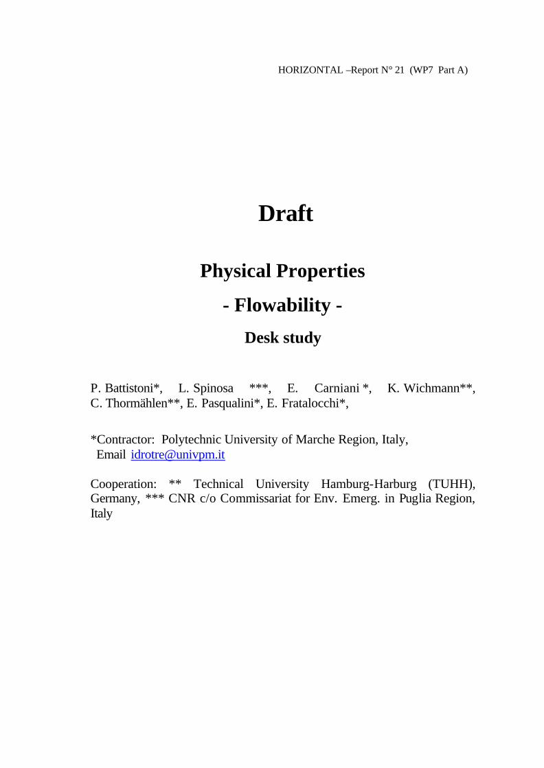
3.1.2 Laboratory or field test feasibility All capillary viscometer tests are laboratory tests; this condition derives by the fact that the tests analysed require the use of a thermostatic condition of material, for this reason capillary viscometers non-well usable in field condition.
3.1.3 Apparatus The tests examined use five types of viscometers:
• Gravity flow capillary viscometers (see Figure 4); • Vacuum capillary viscometers; • Reverse flow capillary viscometers; • Differential pressure stainless steel capillary viscometers; • Screw extrusion capillary rheometers;
Each of them has different geometric dimensions to perform the measurement of rheological parameter in the range of interest; they require a temperature control bath for the material and the apparatus employed.
HORIZONTAL – Report n° 21 25
Figure 4: Gravity flow capillary viscometer (Modified Ubbelohde type)
3.1.4 What is measured and how Normally the test examined measures the following different type of viscosity for Newtonian fluids:
• Apparent viscosity; • Dynamic viscosity; • Kinematic viscosity;
In these cases the kinematic viscosity (the resistance of a fluid to flow under gravity) is determined by measuring the time for a fixed volume of fluid to flow through the capillary calibrated glass viscometers and multiplying it by the viscometer calibration factor. The viscosity or coefficient of viscosity is obtained multiplying the kinematic viscosity for the density of the fluid. Dynamic viscosity is the same of viscosity or coefficient of viscosity. Apparent viscosity is the ratio between apparent shear stress to apparent shear rate. Where apparent shear stress may be determined by measuring the die entrance pressure for a specific

26 HORIZONTAL – Report n°21
die, then applying appropriate geometric factors; apparent shear rate is the shear rate of the material passing through the capillary die. Only in some methods are measured:
• Relative, inherent, intrinsic viscosity • Viscosity index;
All these parameters are related to mass concentration of material:
• relative viscosity the ratio of the viscosity of the solution to the viscosity of the solvent;
• inherent viscosity the ratio of the natural logarithm of the relative viscosity to the mass concentration of the material;
• intrinsic viscosity the limiting value of the reduced viscosity of the inherent viscosity at a infinite dilution of the material examined;
The range of Kinematic viscosity is 0,5-100.000 cSt (centistokes) Where cSt = 1 mm2/s
3.1.5 Material to be examined The test are mainly employed for the following materials:
• Transparent and opaque liquids; • Road oils and bitumens; • Petroleum products; • Dilute polymers solutions • Solutions of polymers; • Thermoplastic compounds;
3.1.6 Feasibility of the methods to the materials for Horizontal project None of the methods examined or of the apparatus used can be transferred to the materials for horizontal project, it can be due to two main factors:
• Materials for horizontal project are o treated bio-waste; o sludges; o soils
None of them have a Newtonian behaviour and the dimension is not feasible with those of gravity or glass capillary rheometers;
• The methods examined are related to laboratory tests not well accepted in a horizontal strategy where the widest diffusion of methods is preferred.
On conclusion all the methods of capillary rheometers section cannot be adopted for Horizontal.
3.2 Penetrometer A lot of standard methods are provided for testing the consistency of a wide range of materials from fluid fresh mortars to solid soils by measuring the resistance to penetration of cylindrical or conical tips. The methods can also be used to establish a relationship between penetrometer resistance and water content of the sample.
HORIZONTAL – Report n° 21 27
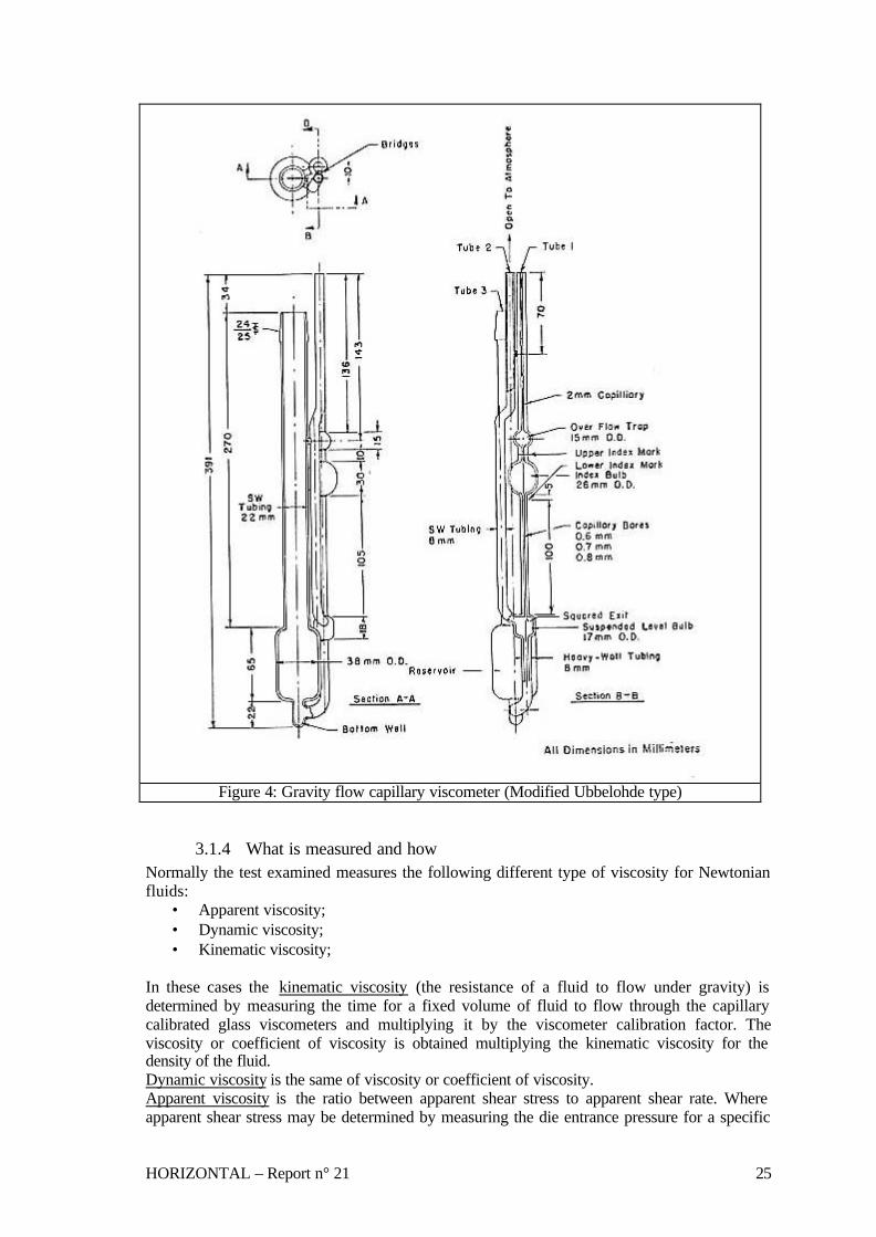
3.2.1 Standards analysed The list of the examined standard methods for the determination of flowability of different materials by penetration tests is summarised in the following table: Method Material Parameter Apparatus Standar
d range Physical meaning/purpose
Utility / field Comments
ASTM C 405 - 82 Standard Practice for Estimating Consistency of Wet-Mixed Thermal Insulating Cement
Thermal insulating cement
Consistency Method A: Dead load tester Method B: Penetration tester
Percentage of deformation of sample under a loading arm Rod penetration in mm after 30 s
The consistency of cement affects such properties as ease of trowelling, wet adhesion, drying shrinkage, dry density and thermal conductivity
-
ASTM C 472-84 Physical Testing of Gypsum Plasters and Gypsum Concrete
Gypsum plasters Gypsum concrete
Physical testing
Modified Vicat apparatus Consistometer
ml of water added to 100 g of the sample to obtain a penetration of 20 mm Resulting patty from conical vessel
-
+
ASTM D 1558 - 84 Moisture Content Penetration Resistance Relationships of Fine-Grained Soils
Fine-grained soil
Penetration resistance
Laboratory soil penetrometer
Pressure necessary to penetrate the soil with a needle of known end area
Relationship between moisture content, density and penetration resistence of a soil
-
ASTM D 3441 - 79 Deep, Quasi-Static, Cone and Friction-Cone Penetration Tests of Soils
Soil and soft rocks
Penetration resistance
Field cone and friction cone penetrometer Mechanical and electric types
Penetration resistance with depth during the steady slow penetration of a pointed rod into soil
Engineering properties of soil related to design and construction of earthworks and foundations for structures
-
UNI EN 1015 - 4 Determination of Consistence of Fresh Mortar
Fresh mortar
Consistency Plunger penetration
Free penetration of a plunger released from a determined height
The result is related to the fluidity or water content of fresh mortar and measures the workability of the product
+
ASTM C 807 - 99 Time of Setting of Hydraulic Cement Mortar by Modified Vicat Needle
Hydraulic Cement Mortar
Consistency Mod. Vicat apparatus
Time required to obtain the stipulate penetration of the sample
Determination of the time of setting of cement expansive
+
ASTM D 2884 - 93 Yield Stress of Heterogeneous Propellants by Cone Penetration Method
Heterogeneous propellants
Yield stress Magnesium penetration cone and cup
42-60 mm of cone penetration at 20°C
Penetration of the cone after 5 s The yield stress is calculated by the use of a proper equation
The yield stress is a measure of the forces required to initiate and maintain flow
+

28 HORIZONTAL – Report n°21
ASTM D 5478 - 98 Viscosity of Materials by Falling Needle Viscometer
Newtonian and non-Newtonian liquids
Viscosity and yield stress
Falling needle viscometer with automatic sensing device. Thermostatic bath
Viscosity range: 5x10⁻⁴ to 103 Pa.s Shear rate range: 10-4 to 103 s-1
The liquid viscosity is determined by measuring the steady -state or terminal velocity of cylindrical needles as they fall through the tests liquid under gravity
Clear and opaque liquids. Rheological properties of varnishes and paints provide information to sag resistance, levelling, etc.
-
ISO/DIS 12058-2.2 Plastics - Determination of Viscosity Using a Falling-ball Viscometer Part 2: Free-Falling Ball Method
Polymers and resins in the liquid emulsified or dispersed
Dynamic viscosity
Vertical-tube falling ball viscometer
700 to 600000 mPs.s
The viscosity is determined by measuring the time taken for a ball to fall between an upper and lower marks at controlled temperature
Used for the determination of relatively high values of viscosity of transparent liquids
-
ISO/DIS 12058-1 1997 Plastics - Determination of Viscosity Using a Falling-Ball Viscometer Part 1: Inclined-tube Method
Polymers and resins in liquid emulsified or dispersed state
Dynamic viscosity
Inclined-tube falling ball viscometer
0,6-250000 mPa.s -20-+120°C
The viscosity is determined by measuring the time taken for a ball to fall between an upper and lower marks in an inclined tube filled with the liquid at controlled temperature
Used for the determination of dynamic viscosity of Newtonian fluids at controlled temperature
-
ISO 12115 1997 Fibre-Reiforced Plastics - Thermosetting Moulding Compounds and Prepregs - Determination of Flowability, Maturation and Shelf Life
Fibre reinforced thermosetting moulding compounds and prepregs
Flowability Method 1: apparatus for applying a constant load to the tests specimen Method 2: Hydraulic moulding press
Method. 1: The sample is subjected to a constant load by a punch at room temperature. The change in height of the punch as it sinks is measured Method 2: The sample is pressed under the commonly used moulding conditions.The force necessary to spread out the sample and to fill the mould within a certain time is measured
Used to assess the influence of individual components of the moulding compound on the moulding behaviour by determining the flowability of the compound
-
BS 2000: Part 49:1993 Petroleum and its Products Part 49. Determination of Needle Penetration of Bituminous Material
Solid and semisolid bituminous material
Consistency Penetration apparatus with conical tip needle Water bath
Usual test conditions: Temp: 25°C Load: 100g Time: 5s
The consistency is expressed as the distance in tenths of mm that a standard needle penetrates vertically into the material under specified conditions of temperature, load and duration of loading
Consistency of bituminous material for road pavements and industrial applications
+

HORIZONTAL – Report n° 21 29
BS 3712: Part 1: 1991 Building and Construction Sealant Part 1. Methods of test for homogeneity, relative density and penetration
Construction sealant
Consistency Penetrometer with penetration needles and penetration cones Thermostatic bath
Usual test conditions: Temp: 25°C Load: from 50 to 150g Time: 5s
The penetration is expressed as the distance in tenths of mm that a standard needle penetrates vertically into the material under specified conditions of temperature, load and duration of loading
Properties of sealant particularly in relation to their compatibility with other materials and to their suitability for application to building joints
-
BS EN 196-3 : 1995 Methods of Testing Cements Part 3. Determination of Setting Time and Soundness
Cement Water corresponding to standard consistence, setting time and soundness
Vicat apparatus with plunger. Le Chatelier apparatus Water bath
The standard consistence of the cement paste corresponds to a sample which produces a distance between plunger and base-plate of 6 mm The setting time corresponds to a needle penetration of only 0,5 mm
The setting time is determined by observing the penetration of a needle into cement paste of standard consistence until it reaches a specified value. The soundness is determined by the volume expansion of cement as indicated by the relative movement of two needles. The water required to obtain a standard consistence of the cement paste is determined by trial penetration tests with different water contents.
Setting time and soundness of cements
-
AFNOR XP T 51-213 Nov. 1995 Plastics- Polymers, Resins in Liquid, Emulsion or Dispersion State, Varnishes, Paints, Oils- Determination of the Dynamic Viscosity Under Low Shear Rate by Vertical Ball Falling
Emulsions or dispersions of various materials
Dynamic Viscosity
Vertical-tube falling ball viscometer Thermostatic bath
0,05-200 Pa.s
The viscosity is determined by measuring the time taken for a ball to fall between an upper and lower marks at controlled temperature
Dynamic viscosity of Newtonian fluids. Apparent viscosity of non-Newtonian fluids. Applicable for production control
-
+ considered for further investigation; - considered not appropriate Table 9: Standards examined for penetrometer
3.2.2 Laboratory or field test feasibility Laboratory penetrometer are quite simple instruments that could also be used for field tests as they do not request electric power supply and can operate at room temperature. The field soil penetrometer are specific apparatus designed to supply data on engineering properties of soil and include cone and friction-cone penetrometer of both mechanical and electric types.

30 HORIZONTAL – Report n°21
3.2.3 Apparatus In the examined methods the following seven apparatus are described: • Laboratory penetration tester with pointed steel rods • Vicat apparatus with cylindrical or conical plunger (see Figure 5) • Laboratory soil penetrometer consisting of specific spring dynamometer and a set of needles
of various end area (see Figure 6) • Field soil penetrometer • Magnesium cone penetrometer for yield stress measurements (see Figure 7) • Falling needle viscometer • Vertical tube falling ball viscometer
Figure 5: Vicat apparatus

HORIZONTAL – Report n° 21 31
Figure 6: Laboratory soil penetrometer
Figure 7: Magnesium Cone Penetrometer
3.2.4 What is measured and how Laboratory apparatus for cement and gypsum consistency tests consist of a frame bearing a movable rod of fixed diameter, loaded with variable weights, with the lower end cylindrical or conical. The standard cone or needle is released from a certain height and allowed to drop freely into the sample. The depth of penetration in a fixed time interval is measured at constant temperature. A graduated scale attached to the frame permits to measure the penetration of the plunger. The results are expressed as mm of rod penetration at the test conditions. The consistency can also be expressed as the number of ml of water to be added to 100 g of the sample to obtain a determined rod penetration.

32 HORIZONTAL – Report n°21
The laboratory soil penetrometer consists of a special spring dynamometer with pressure-indicating scale graduated in kg and an attached needle of known terminal area, selectable among a set of different needles according to the consistency of the sample. The operator shall measure the resistance to penetration of a mixture of soil, sieved at 4,75 mm and compacted with water, by use of the soil penetrometer with attached needle of known area. The results calculated by the ratio between the penetrating force and the needle terminal area are expressed in kPa. The field soil penetrometer measures the end bearing and side friction component penetration resistance, which are developed during the steady slow penetration of pointed rod into soil. The apparatus uses both cone and friction-cone tips and may be mechanical or electric type. The mechanical penetrometer uses a set of inner rods to operate a telescoping penetrometer tips and to transmit the components of penetration resistance to the surface for measurements. The electric penetrometer uses electric -force transducers built into a non-telescoping penetrometer tip for measuring the components of penetration resistance. The results are reported as cone and friction-cone resistance expressed in 100 kPa with depth in metres. The method for yield stress measurement of heterogeneous propellant makes use of a standard magnesium cone penetrometer. The penetration is determined at 25°C by releasing the cone-test rod assembly from the penetrometer and allowing the assembly to drop for 5 s. The cone will be essentially at the rest in less than this time, so the exact timing is not critical. The yield stress is the measure of the maximum shear stress that can be applied without causing permanent deformation and is expressed in Pa. This value is calculated by measuring the cone penetration depth and by using a proper equation that takes into consideration the balance of the involved forces. Both falling needle and falling ball viscometer methods consist of determining the liquid viscosity of fluids by measuring the velocity of cylindrical needles or steel balls as they fall through the test liquid under the influence of gravity. In the falling needle method it is possible to measure the apparent viscosity and the yield stress of non-Newtonian liquids by using a series of needles of the same geometry but different densities.
3.2.5 Material to be examined The methods are utilised to test the following materials: • Thermal insulating cement • Gypsum plaster and concrete • Fine-grained soil • Soil and soft rocks • Fresh mortar and cement • Heterogeneous propellants both of the gel and emulsion type • Polymers and resins emulsified or dispersed in the liquid • Thermosetting moulding compounds and prepregs • Bituminous materials • Construction sealant Generally the materials are in the solid form or as concentrated water suspensions.

HORIZONTAL – Report n° 21 33
3.2.6 Feasibility of the methods to the materials for Horizontal project The laboratory penetrometer designed to test the consistency of fresh mortar, gypsum and concrete could be used to test the flowability of concentrated sludge or sludges at higher dry content as these materials may assume a paste -like consistency. The yield stress determination by cone penetrometer, described in ASTM D 2884 method, could also be applied to test the flowability of concentrated sludge. In fact the yield stress is considered a reliable parameter to test the flowability of non-Newtonian materials. These instruments could also be used for field tests, as they are very simple to operate and do not request electric power supply or accessory apparatus. The soil laboratory penetrometer that is used to test the consistency of compact mixtures of soil and water cannot be used for flowability tests, but it could be utilised to measure the solidity limit. The field soil penetrometer is a special apparatus designed to test very compact material and cannot be used for the scope of the Horizontal project. The falling needle and falling ball viscometers are laboratory devices that can measure the absolute viscosity of various liquids. Their use is not recommended with non-homogeneous fluids due to the uneven falling velocity of the ball or of the needle caused by the presence of coarse particles. Therefore these instruments are not suitable for analyses of Horizontal materials.
3.3 Rotational viscometers Rotational viscometers are commonly used to measure the absolute viscosity of liquids of different physical and chemical characteristics in a wide range of viscosity values. A lot of standard methods are proposed by using different apparatus and procedures according to material and properties to be analysed.
3.3.1 Standards analysed The examined standard methods for the determination of flowability of different substances by rotational viscometers are reported in the following table: Method Material Parameter Apparatus Standard
range Physical meaning/purpose
Utility / field Comments
ASTM D 1084 - 63 Viscosity of Adhesives
Free- flowing adhesives
Viscosity Met. A: consistency cup Met. B: Brookfield viscometer Met. C: Stormer viscometer Met. D: Zahn viscosity cups
50-200000 cP <3000 cP
Time for gravity flow through a calibrated orifice in a consistency cup Viscosity in cP measured with a Brookfield viscometer Time for 100 revolutions in a Stormer viscometer Time for gravity flow through a calibrated orifice in Zahn cups
For newtonian fluid For newtonian fluid For newtonian fluid
-
ASTM D 2196 - 81 Rheological Properties of Non-Newtonian Materials by Rotational Viscometer
Non-newtonian liquids
Rheological properties
Met. A: Brookfield viscometer Met. B: Brookfield viscometer Met. C:
Shear rate 0.1-50 s -1 Shear rate 0.1-50 s -1 Shear rate
Apparent viscosity Shear thinning and thixotropy Shear thinning of sheared mat.
Time dependent materials Time dependent materials
-

34 HORIZONTAL – Report n°21
Brookfield viscometer
0.1-50 s -1
ASTM D 2556 - 69 Apparent Viscosity of Adhesives Having Shear-rate Dependent Flow Properties
Adhesives Apparent viscosity
Rotational viscometer
100-2000000 Cp
Viscosities measured at different shear rates
Non-Newtonian materials
+
ASTM D 2983 - 87 Low-Temperature Viscosity of Automotive Fluid Lubricants Measured by Brookfield Viscometer
Automotive fluid lubricants
Viscosity Brookfield viscometer
1000-1000000 mPa.s -5 to -40°C
Low shear rate viscosity of automotive oils at low temperatures
Fluid lubricants are non-Newtonian at low temperatures
-
ASTM D562 Consistency of Paints Using the Stormer Viscometer
Paints Consistency
Stormer viscometer
Normal range 4 to 14 P at 25°C
Consistency is related to the load in grams required to produce a rotational frequency of 200 rpm for an off-set paddle rotor immersed in the paint
Product control
-
prEN 13702 - 2 Bitumen and Bituminous Binders - Determination of Dynamic Viscosity of Modified Bitumen - Part 2 : Coaxial Cylinders Method
Bitumens Dynamic viscosity
Coaxial cylinder viscometer
Viscosity range 10-1 to 106 Pa.s Shear rate range 1s -1 to 104s-1 Temperature range 60 to 150°C
The viscosities are measured at different shear rates in a coaxial cylinder viscometer with the ratio of radius R1/R2<1,1
Service condidtions of asphalt Conditions at the end of compaction asphalt Conditions during mixing of asphalt
+
prEN 13302 Bitumen and Bituminous Binders - Determination of Viscosity of Bitumen Using a Rotational Spindle Apparatus
Bitumen and bituminous binders
Viscosity Rotating spindle apparatus
50 to 250°C Apparent viscosity at application temperatures
-
UNI 8701 Part 3 Epoxy Resins. Determination of Viscosity by Means of Rotational Viscometer
Epoxy resins Dynamic viscosity
Brookfield viscometer Syncro - Lectric mod. LVF
0,001 - 100 Pa.s
Viscosity of epoxide resin solutions in sutable solvents
-
ASTM D 4016 -93 Viscosity of Chemical Grouts by Brookfield Viscometer (Laboratory Method)
Catalysed chemical grouts
Viscosity Brookfield viscometer
0,001 - 1 Pa.s at 20°C
Resistance to flow of grouts
Penetrability of grouts in soil voids and rock fissures
-
ASTM D 4648 - 00 Laboratory Miniature Vane Shear Test for Saturated Fine- Grained Clayey Soil
Saturated fine-grained clayey soil
Shear strength
Vane blade Vane device with torque measuring system
60-90°/min <100kPa
Determination of torque required causing a cylindrical surface to be sheared by vane. The torque is converted in shear resistance by a calibration constant
Testing consistency and shear strength of clay soils for engineering design and construction
-

HORIZONTAL – Report n° 21 35
ASTM D 4684 - 02a Determination of Yield Stress and Apparent Viscosity of Engine Oils at Low Temperature
Engine oils Yield stress Apparent viscosity
Concentric cylinder mini-rotary viscometer with temperature control system usable at controlled shear stress and controlled shear rate
-10 to -40°C Viscosity measurements at > = 525 Pa and shear rate from 0.4 to 15 s -1
Yield stress and viscosity of oils are measured after cooling at controlled rates over a period exceeding 45 h
Effect of cooling on oil yield stress and viscosity
-
ASTM D 6080 - 97 Defining the Viscosity Characteristics of Hydraulic Fluids
Hydraulic Fluids
Dynamic viscosity at low temperatures Kinematic viscosity at high temperatures
Brookfield viscometer
750 mPa.s from -50 to +16°C from 4 to 150 cSt at 40°C
Provide a better description of the viscosity characteristics of lubricants used as hydraulic fluids
Relationship between viscosity and hydraulic fluid performance
-
ASTM D 6204 - 01 Rubber- Measurement of Unvulcanized Rheological Properties Using Rotorless Shear Rheometers
Raw rubber and unvulcanized rubber compounds
Viscoelastic properties
Torsion strain rotorless oscillating rheometer with a sealed cavity
100 and 125°C Loss modulus G'' Storage modulus G' Dynamic viscosity
Measurement of the viscous torque and elastic torque produced by oscillating angular strain of set amplitude and frequency in a completely closed and sealed test cavity
The rheological properties are related to factory processing
-
ASTM D 6243 - 98 Determining the Internal and Interface Shear Resistance of Geo synthetic Clay Liner by the Direct Shear Method
Geosynthetic clay liner (GCL)
Internal shear resistance
Shear device Normal stress loading device Shear force loading device Displacement indicator
A constant normal stress is applied to the specimen placed in a shear box and a tangential shear force is applied to the apparatus so that one section of the box moves in relation to the other section. The shear force is recorded as a function of the horizontal displacement of the box.
The method is intended to indicate the performance of the selected specimen by attempting to model certain field conditions
-
ASTM D 6821 - 02 Low Temperature Viscosity of Drive Line Lubricants in a Constant Shear Stress Viscometer
Drive line lubricants
Viscosity Yield stress
Mini-rotary constant shear stress viscometer
-40 to 10°C Rotation of the rotor is achieved by applying load acting through a string wound around the rotor shaft. Time of rotation is measured electronically
Evaluate the low temperature performance of driveline lubricant as gear oils, automatic transmission fluids, etc.
+
ISO 2555 1989 Plastics - Resins in the Liquid State or as Emulsions or Dispersions - Determination of Apparent Viscosity by the Brookfield Test Method
Resins in a liquid state
Apparent viscosity
Brookfield- type viscometer
0,02-60000 Pa.s
The viscosity is determined by the torque exerted on the spindle rotating in the product at a fixed rotational frequency.
Applicable to non-Newtoninan fluids The viscosity depends on the velocity gradient to which the product is subjected during the measurement
-

36 HORIZONTAL – Report n°21
ISO 2884-1 1999 Paints and Varnishes - Determination of Viscosity Using Rotary Viscometers- Part 1: Cone and Plate Viscometer Operated at a High Rate of Shear
Paints, varnishes and related products
Dynamic viscosity
Cone and plate viscometer
0,1-1 Pa.s 9000-12000 s-
1
The viscosity is determined by the torque exerted on the cone rotating on a plate where the test liquid is placed. Used for routine high-shear viscosity measurements
The value obtained gives information about the resistance offered by the material to brushing, spraying and roller coating during application
-
ISO 3219 1993 Plastics - Polymers/Resins in the Liquid State or as Emulsions or Dispersions - Determination of Viscosity Using a Rotational Viscometer with Defined Shear Rate
Polymer and resin dispersions or emulsions
Dynamic viscosity
Rotational viscometer with standard geometry operating at defined shear rates and controlled temperature
10-2-103 Pa.s The viscosity is determined by the torque, proportional to the shear stress, measured at defined shear rate
Applicable to Newtonian and non-Newtonian fluids
+
ISO/FDIS 2884-2 2002 Final Draft Paints and Varnishes - Determination of Viscosity Using Rotary Viscometers Part 2: Disc or Ball Viscometer Operated at a Specified Speed
Paints, varnishes and related products
Dynamic viscosity
Rotary viscometer with disc and ball spindles operating at controlled temperature
Up to 34 Pa.s The methods gives only relative test results due to undefined velocity gradients
Applicable mainly during production and thinning
-
NF T 30-029 Oct. 1980 Paints - Method of Use a Rotational Viscometer for Measuring the Apparent Dynamic Viscosity of Varnishes, Paints and Similar Preparations
Paints, varnishes
Apparent dynamic viscosity
Rotational viscometer with standard geometry operating at defined shear rates and controlled temperature
from 25x10-3
to 8x10³ Pa.s The viscosity is determined by measuring the torque, proportional to the shear stress, at defined shear rate
Applicable to production control
+
+ considered for further investigation; - considered not appropriate Table 10: Standards examined for rotational viscosimeters
3.3.2 Laboratory or field test feasibility As a small variation of sample temperature will result in a significant change in viscosity, all the tests must to be carried out in laboratory using a thermostatic bath or at carefully controlled room temperature.
3.3.3 Apparatus Different types of rotational viscometers are reported in the methods: • Brookf ield viscometers (see Figure 8) • Coaxial cylinder viscometers (see Figure 9) • Stormer viscometers (see Figure 10) • Vane device with torque measuring system • Controlled shear stress and controlled shear rate mini-rotary viscometer
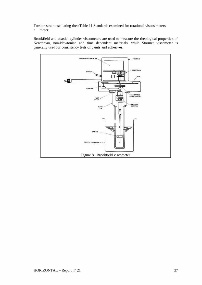
HORIZONTAL – Report n° 21 37
Torsion strain oscillating rheo Table 11 Standards examined for rotational viscosimeters • meter Brookfield and coaxial cylinder viscometers are used to measure the rheological propertie s of Newtonian, non-Newtonian and time dependent materials, while Stormer viscometer is generally used for consistency tests of paints and adhesives.
Figure 8: Brookfield viscometer
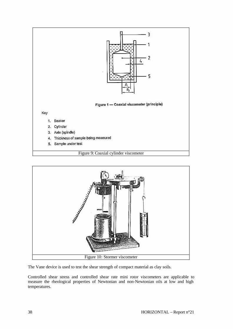
38 HORIZONTAL – Report n°21
Figure 9: Coaxial cylinder viscometer
Figure 10: Stormer viscometer
The Vane device is used to test the shear strength of compact material as clay soils. Controlled shear stress and controlled shear rate mini rotor viscometers are applicable to measure the rheological properties of Newtonian and non-Newtonian oils at low and high temperatures.

HORIZONTAL – Report n° 21 39
To test the viscoelastic properties of materials as rubber compounds a torsion strain oscillating rheometer is proposed.
3.3.4 What is measured and how In rotational viscometers the fluid sample contained in a cylindrical cup is sheared as a result of the rotation of an internal cylinder or paddle -type rotor. Brookfield and coaxial cylinder viscometers utilise an apparatus that consists of an internal cylinder (bob) rotating in a static outer cylinder (cup) filled with the liquid to be examined immersed in a thermostatic bath at controlled temperature. The rotor is driven at fixed or programmed speeds by a DC motor. The resistance of the sample to flow is defined by measuring the torque applied to the rotor at the set speed. Signals proportional to the speed and torque are transmitted to a control unit for processing and display. By using a set of spindles and different rotational speeds a variety of viscosity range can be examined. For Newtonian liquids the results are expressed as dynamic viscosity in Pa.s. The dynamic viscosity is defined as the ratio between the applied shear stress (Pa) proportional to the torque and the shear rate (s-1) proportional to the rotating speed. For non-Newtonian liquids the following additional information can be obtained: • Shear thinning index
This index is calculated dividing the apparent viscosity at low rotational speed by the viscosity at a speed ten times higher. The higher the ratio the greater the shear thinning index.
• Degree of thixotropy The degree of thixotropy is measured by increasing and decreasing the viscometer speed stepwise and recording the viscosity values after ten revolutions at each speed. The degree of thixotropy is calculated from the ratio of the slowest speed viscosity taken with increasing speed to that with decreasing speed. The degree of thixotropy can also be calculated by the ratio of the slowest speed viscosity taken after rest period to that before the rest period. The higher the ratio the greater is the thixotropy.
Stormer viscometer consists of a double flag paddle -type rotor immersed in a cylindrical cup containing the sample. The rotor is driven (via a cord and pulley arrangement) by a falling weight. The standard defines the consistency as the weight required to producing a rotation frequency of 200 rpm. The consistency of paints applied to brush or rollers is generally expressed in Krebs Units (KU). This scale is the log function of the load necessary to produce 200 rpm. A calibration of the viscometer with different standard oils having assigned value of load to produce 200 rpm permits the conversion of load in grams to absolute viscosity in P. The normal range of the Stormer is covered by standard oils having a viscosity from 4 to 14 P (from 400 to 1400 mPa.s). The miniature vane shear test may be used to obtain estimates of the shear strength of fine-grained soils.The vane assembly shall consist of four rectangular blades vane inserted in a cylindrical tube containing the sample that is rotated at a constant rate of 60 to 90°/min by a motorised vane device. The torque required to cause a cylindrical surface to be sheared by the vane is measured by a torque transducer. The torque is then converted to a unit shearing resistance (Pa) of the cylindrical surface area by means of a vane blade calibration constant. The rheological properties of viscoelastic material are measured by torsion strain oscillating rheometers. The elasticity of the sample is proportional to the delayed response between preset
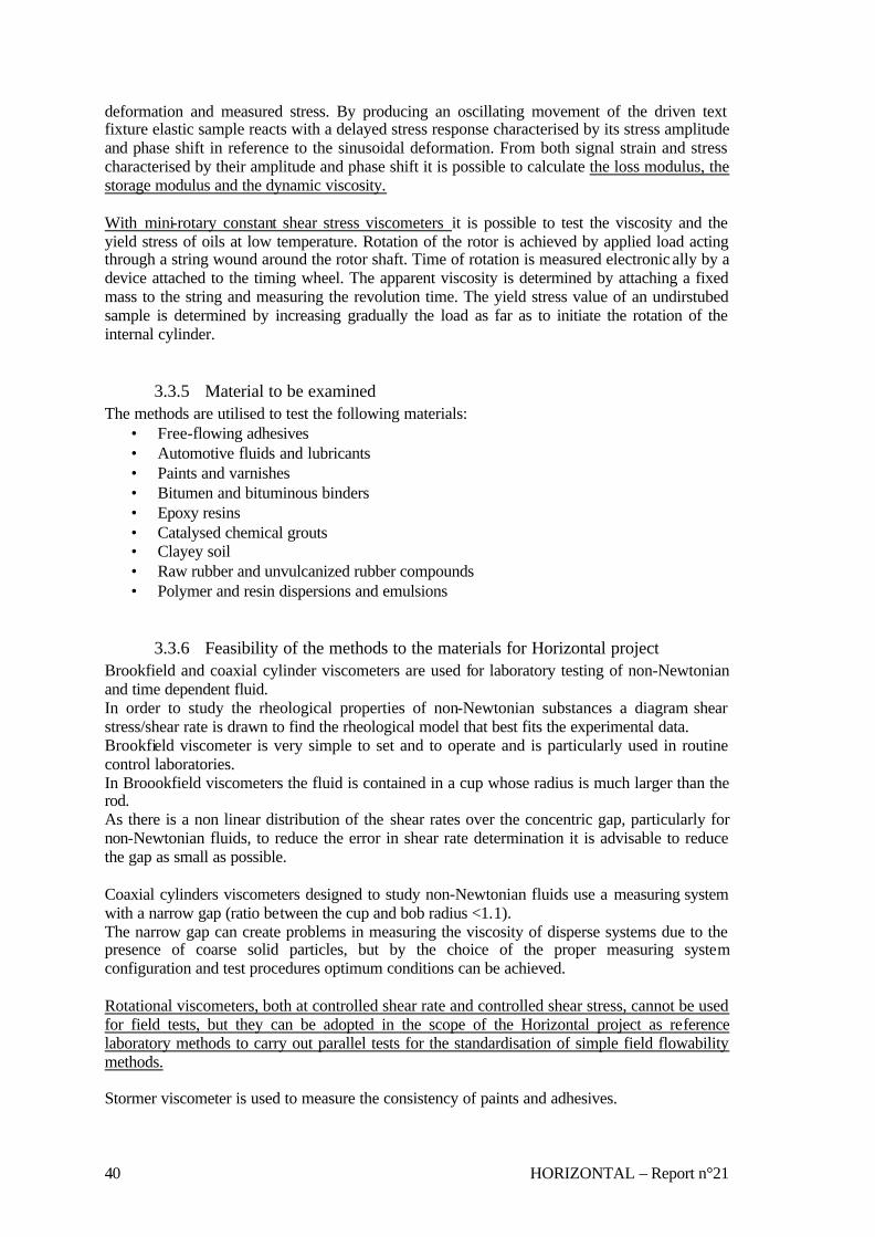
40 HORIZONTAL – Report n°21
deformation and measured stress. By producing an oscillating movement of the driven text fixture elastic sample reacts with a delayed stress response characterised by its stress amplitude and phase shift in reference to the sinusoidal deformation. From both signal strain and stress characterised by their amplitude and phase shift it is possible to calculate the loss modulus, the storage modulus and the dynamic viscosity. With mini-rotary constant shear stress viscometers it is possible to test the viscosity and the yield stress of oils at low temperature. Rotation of the rotor is achieved by applied load acting through a string wound around the rotor shaft. Time of rotation is measured electronic ally by a device attached to the timing wheel. The apparent viscosity is determined by attaching a fixed mass to the string and measuring the revolution time. The yield stress value of an undirstubed sample is determined by increasing gradually the load as far as to initiate the rotation of the internal cylinder.
3.3.5 Material to be examined The methods are utilised to test the following materials:
• Free-flowing adhesives • Automotive fluids and lubricants • Paints and varnishes • Bitumen and bituminous binders • Epoxy resins • Catalysed chemical grouts • Clayey soil • Raw rubber and unvulcanized rubber compounds • Polymer and resin dispersions and emulsions
3.3.6 Feasibility of the methods to the materials for Horizontal project Brookfield and coaxial cylinder viscometers are used for laboratory testing of non-Newtonian and time dependent fluid. In order to study the rheological properties of non-Newtonian substances a diagram shear stress/shear rate is drawn to find the rheological model that best fits the experimental data. Brookfield viscometer is very simple to set and to operate and is particularly used in routine control laboratories. In Broookfield viscometers the fluid is contained in a cup whose radius is much larger than the rod. As there is a non linear distribution of the shear rates over the concentric gap, particularly for non-Newtonian fluids, to reduce the error in shear rate determination it is advisable to reduce the gap as small as possible. Coaxial cylinders viscometers designed to study non-Newtonian fluids use a measuring system with a narrow gap (ratio between the cup and bob radius <1.1). The narrow gap can create problems in measuring the viscosity of disperse systems due to the presence of coarse solid particles, but by the choice of the proper measuring system configuration and test procedures optimum conditions can be achieved. Rotational viscometers, both at controlled shear rate and controlled shear stress, cannot be used for field tests, but they can be adopted in the scope of the Horizontal project as reference laboratory methods to carry out parallel tests for the standardisation of simple field flowability methods. Stormer viscometer is used to measure the consistency of paints and adhesives.

HORIZONTAL – Report n° 21 41
This equipment operates at a fixed shear rate and can be utilised, by calibration with standard oils, for measuring the viscosity of Newtonian substances in the limited range between about 200 to 5000 mPa.s. The Stormer viscometer method is not usable with non-Newtonian or thixotropic fluids where viscosity is a function of the shear rate and previous history of the sample. Therefore Stormer viscometer cannot be adopted for the purpose of Horizontal project. The miniature vane shear test method is applied to measure the shear strength of fine-grained soils but cannot be used to test the flowability of sludges.
3.4 “Flow” apparatus Flow analysers described in the selected methods are quite simple devices used in empirically way to test the fluidity or consistency of various materials for quality control purpose. Generally the time for fluid material to flow under gravity from a standardised vessel through an orifice or through a tube is measured. For paste-like substances the consistency is expressed as the diameter occupied by a cone shaped sample after it has been spread on a vibrating table or by the measure of the compactability time. For pourable fluids the consistency may be determined by measuring the distance covered by the sample freely flowing along a horizontal channel. The disadvantage with many of these simple instruments is their inability to generate more than one value to characterise the fluid.
3.4.1 Standards analysed The list of standards methods examined for flow tests of different materials is reported in the following table. Method Material Parameter Apparatus Standard
range Physical meaning/purpose
Utility / field Comment
s C 230 - 83 Flow table for Use in Tests of Hydraulic Cement
Mortars Flow properties
Flow table and frame Mold for casting the flow specimen
Measure of the diameter of the mortar after it has been spread by operation of the table
Flow test for consistency of mortars
-
ASTM C 639 Rheological (Flow) Properties of Elastomeric Sealants
Single-component and multi-component joint sealants
Flow properties
Flow channels Refrigerator Oven
4.4 and 50 °C
Measure of the degree of horizontal or vertical flow of sealants at two pre-determined temperatures
Rheological properties of single and multicomponent chemically curing sealants for use in building construction
-
ASTM C 939 - 81 Flow of Grout for Preplaced-Aggregate Concrete
Grout mixtures
Flow properties
Flow cone Efflux time of 35 s or less
The fluidity of the concrete is measured by the time of efflux of a specified volume of grout from a standardised cone
Determination of the fluidity of grout mixtures to be used for the production of PA concrete
+

42 HORIZONTAL – Report n°21
ASTM D 1084 - 63 Viscosity of Adhesives
Free- flowing adhesives
Viscosity Met. A: consistency cup Met. B: Brookfield viscometer Met. C: Stormer viscometer Met. D: Zahn viscosity cups
50-200000 cP <3000 cP
Time for gravity flow through a calibrated orifice in a consistency cup Viscosity in cP measured with a Brookfield viscometer Time for 100 revolutions in a Stormer viscometer Time for gravity flow through a calibrated orifice in Zahn cups
For newtonian fluid For newtonian fluid For newtonian fluid
-
ASTM D 1725 - 62 Viscosity of Resin Solutions
Resin solution
Viscosity Viscosity tubes and holder
Time for mean bubble travel
Bubble sec. is appr. equal to stokes
-
ASTM D 4318 - 84 Liquid Limit, Plastic Limit, and Plasticity Index of Soils
Soils Water content corresponding to: Liquid limit Plastic limit Plasticity index
Liquid limit device consisting of a cup and a carriage designed to drop it onto a hard base
The liquid limit is determined by dividing the sample in the cup in two parts and then allowing to flow together by repeatedly dropping the cup. The plastic limit is determined by rolling the sample until its water content cause the thread to cramble
The method is used for engineering classification of the fine-grained fraction of the soil
-
prEN 14117 DRAFT Products and System for the Protection and Repair of Concrete Structures - Test Methods - Determination of Viscosity of Cementitious Injection Products
Cementitious injection products
Viscosity Flow cone 21°C 60% relative humidity
The fluidity of cementitious products is measured from the time of efflux of a certain volume of the sample from a standardised cone
Determination of the technical characteristics of the product
+
prEN 13880 - 5 Hot Applied Joint Sealants - Part 5: Test Method for the Determination of Flow Resistance
Road material
Flow Resistance
Metal frame, metal plate, metal stand
60°C The flow resistance is calculated by measuring the movement along the lower transverse edge of a sample positioned on a metal plate inclined at an angle of 75° at a test temperature of 60°C
Control of the technical properties of the product
-
UNI 20065 Petroleum Products and Lubricants Determination of Pour Point
Petroleum products and lubricants
Pour point Test jar + cooling bath
Normal range -38 to +50°C
Lowest temperature at which movement of oil is observed
Lowest temperature at which the oil is usable
-
UNI 5656 - 65 Waterproofing of Roof - Asphalt Mastics - Determination of the Flow on a Sloping Plane
Asphalt mastics
Fluidity Sloping plane Oven
65°C Measure of flow of asphalt mastics placed on specimens inclined of 45° at 65°C for 8 hours
Measure of resistance of asphalt mastics to move by flow on a sloping plane at the test temperature
-

HORIZONTAL – Report n° 21 43
UNI 5662 - 65 Waterproofing of Roof - Asphalt Grouts - Determination of the Flow on a Sloping Plane
Asphalt grouts
Fluidity Sloping plane Oven
65°C Measure of flow of asphalt grouts placed on specimens inclined of 45° at 65°C for 8 hours
Measure of resistance of asphalt grouts to move by flow on a sloping plane at the test temperature
-
UNI 8997 Superplastic Mortars Determination of Consistency by a Flow Apparatus
Preblended Expansive Mortars for Grouting
Consistency Funnel and flow channel
Consistency is expressed in cm of flow of the sample in a horizontal channel
The method is applicable to fluid products
-
UNI 9417 Fresh Concrete Classification of Consistency
Fresh Concrete
Classification of Consistency
Slump test Vebè test Compactability Flow Index
Subsidence of the cone Vebè time (s) Compactability Index Spreading in % and in mm
-
UNI EN 12350 - 3 Testing Fresh Concrete Vebè Test
Concrete Consistency Vebe meter (Consistometer) Mould
5 to 30 s Measure of deformation of concrete slump in static conditions. Time in seconds for a transparent disc lowered in contact with the surface of the concrete slump to be fully in contact with it under vibrating conditions. (Vebe time)
Consistency of fresh concrete to measure its workability
-
UNI EN 445 Grout for Prestressing Tendons Test Methods
Grout Fluidity Tube and plunger Flow cone
Method 1 (penetrometer): the fluidity is measured by the time of free penetration of a piston in the grout Method 2 (flow cone): the fluidity is measured by the time of efflux of a specified volume of grout from a standardised cone
Injection of grout in prestressed concrete constructions
+
UNI EN ISO 12115 Fibre-Reinforced Plastics Thermosetting Moulding Compounds and Prepregs Determination of Flowability, Maturation and Shelf Life
Fibre-reinforced plastics
Flowability, maturation and shelf life
Apparatus for the application of a constant load on the test tube. Hydraulic press for moulding
Method 1: Deformation of the sample under a loaded punch Method 2: Determination of hydraulic pressure for moulding at test temperature
Properties influencing the moulding process
-
UNI EN ISO 7808 - 2000 Plastics Thermosetting Moulding Materials Determination of Transfer Flow
Plastics Fluididy Hydraulic press Mold
165°C The transfer fluidity is calculated by the mass of material passed through the piston during hot moulding
Production control
-
UNI ISO 4534 Vitreous and Porcelain Enamels - Determination of Fluidity Behaviour - Fusion Flow Test
Molten enamel
Fluidity Press Flow plate and tilting frame Oven
Measure of the length and the maximum breadth of melted specimens permitted to flow at an angle of 45° for an agreed
Fluidity behaviour of vitreous and porcelain enamels
-

44 HORIZONTAL – Report n°21
period
ASTM C 1362 - 97 Flow of Freshly Mixed Hydraulic Cement Concrete
Concrete Fluidity Perforated hollow tube and Inner calibrating rod
Up to 37,5 mm in size
The concrete is allowed to flow into the hollow tube through its perforations. An inner-calibrating rod measures the height of penetrated concrete.
Laboratory and field method to test the flow and consistency of freshly mixed concrete and its change with time
-
ASTM C 143/C 143M - 00 Slump of Hydraulic -Cement Concrete
Concrete Consistency Mold Up to 37,5 mm in size
The height of a cone shaped sample is measured after subsidence. The result is reported as slump test.
Laboratory and field method to test the consistency of hydraulic cement concrete
-
ASTM C 1437 - 01 Flow of Hydraulic Cement Mortar
Hydraulic cement mortar
Fluidity Consistency
Flow table Flow mold Calliper
A cone shaped sample is submitted to operation of a vibrating table The spread is measured and the consis tency of the sample is expressed as percentage of the original base diameter
Determination of the water content that provides a specified flow level
-
ASTM C 1445 - 99 Measuring Consistency of Castable Refractory Using a Flow Table
Castable refractory
Fluidity Consistency
Flow table Flow mold Calliper
A cone shaped sample is submitted to operation of a vibrating table The spread is measured and the consistency of the sample is expressed as percentage of the original base diameter
Determination of the correct water amount to obtain the required consistency of refractory castable
-
ASTM D 6103 - 97 Flow Consistency of Controlled Low Strength Material (CLSM)
CLSM Flow consistency
Flow cylinder
Up to 19 mm in size
An open-ended cylinder is filled with fresh CLSM. The cylinder is raised so the sample will flow into a patty. The average diameter is reported as the consistency of the CLSM.
Determination of the flow consistency of CSLM mixtures for use as backfill or structural fill
-
ASTM D 6351 - 99 Determination of Low Temperature Fluidity and Appearance of Hydraulic Fluids
Hydraulic fluids
Fluidity after storage at low temperature
Test jar + cooling bath
Lowest temperature at which the oil remains fluid and homogeneous after seven days
Oil ability to withstand prolonged exposure to cold temperature
-
ASTM F 1080 - 93 Determination the Consistency of Viscous Liquids Using a Consistometer
Viscous liquids
Consistency Consistometer
The consistency is expressed as the distance of flow of the sample in a horizontal direction
Flow performance of viscous materials
-

HORIZONTAL – Report n° 21 45
BS EN 12350-3:2000 Testing Fresh Concrete Part 3: Vebe test
Fresh concrete
Consistency Vebe meter (Consistometer) Mould
5-30 s
Measure of deformation of concrete slump in static conditions. Time in seconds for a transparent disc lowered in contact with the surface of the concrete slump to be fully in contact with it under vibrating conditions (Vebe time)
Consistency of fresh concrete with low/medium workability
-
ISO 2431 1993-02-15 Paints and Varnishes - Determination of Flow Time by Use of Flow Cups
Paints, varnishes and related products
Consistency Flow cups with orifice diameters of 3, 4, 5 and 6 mm
Flow time 30 - 100 s Kinematic viscosity up to 700 cSt
Time in seconds required for the material under test to flow from the orifice of the filled cup at controlled temperature.
Determination of flow properties of Newtonian or near-Newtonian materials for quality control and development of products.
+
ISO 4103 1979 Concrete - Classification of Consistency
Concrete Classification of Consistency
Vebe test Slump test Compactability
Vebe time Subsidence of the cone Compactability Index
-
NF P 94-052-1 November 1995 Soil: Investigation and Testing - Atterberg Limit Determination - Part 1: Liquid Limit - Cone Penetrometer Method
Soil Liquid limit Cone penetrometer
The liquid limit is the water content of soil to which correspond a cone penetration of 17 mm
The liquid limit charac terizes the geotechnical properties of the soil
-
BS 1881: Part 102 : 1983 Testing Concrete Part 102. Method for Determination of Slump
Concrete of medium to high workability
Consistency Mould made of metal
Suitable for concrete with slump between 5 and 175 mm and aggregates less than 40 mm
The height of a cone shaped sample is measured after subsidence. The result is reported as slump test.
Determination of cohesiveness and workability of concrete
-
BS 1881: Part 105 : 1984 Testing Concrete Part 105. Method for Determination of Flow
Concrete Fluidity Consistency
Flow table that can be lifted manually and let to fall freely from a fixed height. Mould made of metal
Suitable for concrete with aggregates not exceeding 20 mm
The test determines the consistency of fresh concrete by measuring the spread of concrete on a flat plate which is subjected to jolting
Consistency of concrete of very high workability
-
BS EN 1015-3:1999 Methods of Test for Mortar for Masonry Part 3: Determination of Consistence of Fresh Mortar(by Flow Table)
Fresh mortar
Fluidity Consistency
Flow table with horizontal shaft and lifting cam. Mould made of metal
The test determines the consistency of fresh concrete by measuring the spread of concrete on a flat plate which is subjected to jolting
Consistency of freshly mixed mortar that gives a measure of its deformability when subjected to stress
-
BS EN 12274-3:2002 Slurry Surfacing- Test Methods Part 3: Consistency
Slurry surfacing mixtures
Consistency Mould made of metal or hard plastic in the form of a frustum of a cone Table Measuring
The slurry mixture previously supported by the mould is allowed to flow on the table. The outflow is measured on the sheet after 10
The method is used as a mix design aid to determine the amount of water required forming a stable workable
-

46 HORIZONTAL – Report n°21
sheet with eight concentric circles each increasing in radius by 10 mm
s at four points 90° apart from the "0" circle, averaged and recorded as mm flow and % by mass of pre-wetting water
mixture for roads, airfields etc.
BS EN 12350-5:2000 Testing Fresh Concrete Part 5:Flow Table Test
Fresh concrete
Fluidity Consistency
Flow table that can be lifted manually and let to fall freely from a fixed height. Mould made of metal
Suitable for concrete with aggregates up to 63 mm in size
The test determines the consistency of fresh concrete by measuring the spread of concrete on a flat plate which is subjected to jolting.
Consistency of freshly mixed concrete with very high workability
-
BS EN 12350-4:2000 Testing Fresh Concrete Part 4:Degree of Compactability
Fresh concrete
Compactability
Container Trowel Means of compacting the concrete
Suitable for concrete with aggregates up to 63 mm in size
The degree of compactability is determined by completely filling a container with the sample and measuring the distance from the top of the surface of the concrete compacted by vibration
Consistency of freshly mixed concrete with medium/high workability
-
NF P 18-507 Nov. 1992 Additions for Concrete-Water Retention--Method for Measurement of Fluidity by Flowing with the "Cone de MARSH"
Additives (fillers or fly ash) for concrete
Flow properties % water request
Flow cone with a stem with orifice diameter of 8 mm
Determination of water request in % of solid material necessary to obtain an efflux time of 20 seconds
Determination of the fluidity of concrete mixtures
+
NF P 18-358 Jul. 1985 Admixtures for Concretes, Mortars, and Grouts-Routine Grouts for Prestressing Ducts -Measurement of Fluidity and Water Reduction
Mixtures for concrete, mortar and grout
Flow properties Water reduction
Flow cone with a stem with orifice diameter of 10 mm and a length of 60 mm Sieve with openings of 3 mm
Determination of water reduction of a additivated sample with respect to a non-additivated sample having the same fluidity (the same efflux time)
Determination of the fluidity of concrete mixtures
+
Schulze von B., et al., 1991
Sintetic sludges
Tube extrusion viscometer Kasumeter
Determination of the height of the sludge suspension remaining in the container at the end of continuous flow
+
+ considered for further investigation; - considered not appropriate Table 12: Standards examined for flow apparatus
3.4.2 Laboratory or field test feasibility Many of the selected flow methods may be utilised for field tests as they make use of simple equipment and analytical procedures.
3.4.3 Apparatus In the examined methods the following main types of apparatus are described: • Flow table
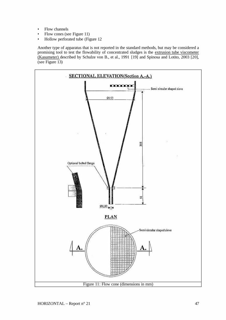
HORIZONTAL – Report n° 21 47
• Flow channels • Flow cones (see Figure 11) • Hollow perforated tube (Figure 12 Another type of apparatus that is not reported in the standard methods, but may be considered a promising tool to test the flowability of concentrated sludges is the extrusion tube viscometer (Kasumeter) described by Schulze von B., et al., 1991 [19] and Spinosa and Lotito, 2003 [20], (see Figure 13)
Figure 11: Flow cone (dimensions in mm)

48 HORIZONTAL – Report n°21
Figure 12: Hollow perforated tube for flow tests
Figure 13: Tube extrusion viscometer (kasumeter)

HORIZONTAL – Report n° 21 49
3.4.4 What is measured and how Flow tables are used to test the consistency of mortar and fresh concrete by submitting a conical sample to operation of a vibrating table. The consistency is expressed as % or mm of sample spread on the table after vibration. In the Vebè test the time necessary for the compactability of a conical sample put on a vibrating table is measured. Flow channel apparatus is used to test the consistency of pre-blended expansion mortars for grouting and other pourable fluid substances. A determined volume of the sample is introduced in a funnel placed upright over a horizontal channel. The sample is let to flow from the funnel into the channel and the consistency is determined by measuring the distance covered by the sample along the channel. The fluidity of cementitiuos injection products and other fluid substances is often measured by the flow cone method. A specified volume of the sample is introduced in a standardised cone put in a stand in vertical steady position. The sample is let to flow from the cone into a receiving container through a calibrated discharge tube. The fluidity of the product is expressed as efflux time measured in seconds. To avoid unevenly flow or a complete stop of the flow due to the presence of course solid particles or lumps of unmixed material, the flow cone is provided with a semicircular shaped sieve for a pre-treatment of the sample. The accuracy of the apparatus is periodically tested by using water as reference fluid. Flow test method in accordance with ASTM C 1362 measures the flow of concrete or mortar into a perforated tube. This method is applicable for concrete with coarse aggregates less than 37,5 mm in diameter. The instrument consists of hollow perforated tube that is inserted in the concrete sample, after which the material is allowed to flow into the hollow tube. The height of sample in the hollow tube measured by a calibrating rod is considered a measure of the flow properties of the concrete. The extrusion tube viscometer (Kasumeter) consists of a cylindrical container to which calibrated pipes of different diameters can be fixed at the bottom. By measuring the height of the sludge suspension remaining in the container at the end of continuous flow, the yield stress can be calculated. The yield stress value is considered a reliable parameter to define the flowability of non-Newtonian fluid as sludges at different total solid content.
3.4.5 Material to be examined The methods are used to test the following materials: • Mortar and grout mixtures • Free-flowing adhesives • Soil • Cementitious injection products • Fresh concrete • Castable refractory • Hydraulic fluids • Sludges • Paints and varnishes

50 HORIZONTAL – Report n°21
3.4.6 Feasibility of the methods to the materials for Horizontal project Flow table methods cannot be used for the evaluation of flowability of sludges as they are designed to test the consistency of high concentrated materials with none or poor tendency to flow. Flow channels are used as laboratory and field tests to analyse the flow properties of pourable fluids. The results obtained with this empirical equipment are utilised only for quality control purpose and are not comparable with viscosity values measured by reference laboratory methods. It follows that flow channel methods cannot be applied for the determination of flowability of Horizontal materials. Flow cones are simple devices commonly used for laboratory and field analyses of relative viscosity of fluid substances. Often for Newtonian fluids the results can be converted into absolute viscosity values by calibration with standards. For non-Newtonian and time dependent fluids the use of flow cone is not recommended. In fact Newtonian fluids flow out from the cone at constant rate because their flow rate is independent of shear rate. On the contrary non-Newtonian fluid flow out at different initial and final velocity due to the decrease of shear rate caused by the decreasing hydrostatic force. Hence for such substances the efflux time is not linearly dependent on viscosity. Materials that are highly thixotropic generate flow time that are much longer than that predicted by steady-state concentric cylinder data because the total shear in flow cones is small compared with that of rotational viscometers. The hollow perforated tube is a specific device for laboratory and field testing of concrete consistency. For field analyses of higher concentrated sludges, for which the value of yield stress can be considered a good indicator of their flowability, the application of a simple specific apparatus as extrusion tube viscometer (Kasumeter) should be evaluated. In conclusion both flow cone and extrusion tube viscometer seem to be the most interesting devices to be utilised as field-tests for the determination of flowability of Horizontal materials. In particular flow cone could be used with diluted sludges that show an approximately Newtonian behaviour, while the extrusion tube viscometer could be applied to the analysis of yield stress of non-Newtonian concentrated sludges. The yield stress can be also measured by a slump test for evaluating materials that can change from paste-like to liquid behaviour with time due to their elasticity. In any case the development of reliable analytical procedures and the validation of the obtained results should be confirmed by parallel reference laboratory tests performed with rotational viscometers.

HORIZONTAL – Report n° 21 51
4. CRITICAL POINT AND RECOMMENDATIONS
In this section mainly the methods with the expression “Considered for further investigation” in the column “Evaluation” in chapter 3 are discussed. Standardization procedures for Horizontal material examination will consist of:
o sampling, transport, preservation and storage, o pre-treatment, o measurement and evaluation of results
4.1 Flowability
4.1.1 Comparison (discussion: pro/contra) Flow cone apparatus (existing method/parameter) Water and wastewater sludges, treated bio-waste and soil can have a rheological behaviour similar to Newtonian fluids, non reference number of rheological properties and time flow are suggested or recommended, this simple measurement apparatus allows to have information useful in sludges, soil, mixture of cement and soil handling and managing; Contra: The flow cone apparatus is suitable only for Newtonian fluids like soil. The use for other Horizontal material of commercial apparatus or the best geometrical dimension must be investigated in further experimental work. Sludges and treated bio-waste can contain coarse particles that can occlude the discharge orifice, a sieving pre-treatment is necessary, flow cone apparatus has been already modified to absolve also this function using for soil but it must be verified for sludge and treated bio-waste. Pro: flow cone is a simple, not expensive and easy to use apparatus, it does not require electrical power supply and specialized personnel for its use. Vicat and Magnesium Cone penetrometers (-existing method/parameter) The test measures the consistency in samples at high solid concentration, the measurement is used to characterize sewage and water works sludges. Contra: :”penetration cone”, Vicat apparatus (ASTMC 472-84; ASTMC 807-99) measures only the sample deformation. An absolute value of yield stress is obtained with magnesium penetrometer (ASTMD 2884-93); for field application a stable plane is necessary. Pro: Magnesium cone penetrometer is a simple apparatus easy to use suitable for testing in both laboratory and field, the measure is very fast ( 5 sec) and the yield stress obtained can be compared with results of reference laboratory method. Extrusion tube viscometer (Kasumeter) The apparatus is not standardized, by measuring the height of the sludge suspension remaining in the container at the end of continuous flow, the yield stress can be calculated.

52 HORIZONTAL – Report n°21
Contra: A pre-treatment of sample is required almost using calibrated pipes at lower diameters; the pipe diameter and time required to execute the test must be optimized. Pro: the apparatus is simple and offers a direct measure of yield stress, it constitutes a field apparatus easy to use; previous investigation of its employment for mineral sludges [18] showed a good correlation with laboratory results of yield stress up to 40 Pa. Further experimental work is needed to clarify the suitability for Horizontal materials. Rotational viscometer Rotational viscometers are commonly used to measure the absolute viscosity of liquids of different physical and chemical characteristics in a wide range of viscosity values. Pro: “rotational viscometer” (existing method/parameter) The apparatus can be used for every flow curve of the fluid, or time depending fluids to determine the absolute viscosity and rheological properties. Contra: (existing method/parameter) The narrow gap between rotational and fixed cylinders, concentration gradient of samples and the high investment cost limit the use of this apparatus only for a laboratory use. In addition the shear rate is highly dependant of velocity profile inside the gap and consequently, the data given by the rheometer are false (the sheared thickness of the material is smaller than expected). All apparatus used Contra: The fluid which gradually changes its physical state from liquid to gel cannot be measured with methods proposed; a simple apparatus energy spending must be employed together with the selected methods.
4.1.2 Recommendations
4.1.2.1 Laboratory reference Laboratory test (method 1): Rotational viscometer apparatus must be used Controlled shear rate rotational viscometers are laboratory devices for determining absolute viscosity of Newtonian and non-Newtonian substances in a wide range of viscosity values. They can be used to test the viscosity of sludges or to correlate rheological properties with field test results. In order to avoid the problems connected with unsheared regions a comparison between rotational and torque viscometers will be performed. Recommendations: pre-treatment of samples for cell narrow gaps, temperature control.
4.1.2.2 Field test Field Test (method 1): “flow cone apparatus” Viscosity is related to the time for a determined volume of sample to empty the cone by flowing under gravity though a calibrated discharge tube. Recommendations: pre-treatment of samples, optimization of geometric dimensions and devices. Field Test (method 2): “Magnesium penetration cone”

HORIZONTAL – Report n° 21 53
Magnesium penetration cone method, as reported in ASTM D2884, allows the yield stress to be quantitatively determined. Recommendation: a stable stand, free of vibration must be supplied. Field test (method 3): “Extrusion tube viscometer” (Kasumeter) The use of an extrusion tube viscometer is a promising method for field determination of the yield stress of high concentrated slurries. The method is not standardised. The apparatus consists of a calibrated pipe 200 mm long of different diameters placed at the bottom of a cylindrical vessel filled with the sample. Measuring the time of flow until it is continuous and the height of the suspension remaining in the cylinder at the end of the continuous flow, the yield stress can be calculated. This method allows to determine the quantitative value of the yield stress. Recommendations: optimization of geometric dimensions of apparatus and devices, pre-treatment especially for Horizontal materials with gel-sol or sol-gel transformation.
4.2 Summary of recommended methods The methods selected for further investigation are reported in Table 13 and can be divided in two groups: laboratory and field methods. Table 13 Overview of recommendations Method Employment Shear controlled coaxial cylinders viscometer Laboratory test Flow cone Field test Penetration cone for yield stress measurement Field test Extrusion tube viscometer (Kasumeter) Field test
4.3 Research needs
4.3.1 Basics of methods Methods proposed will measure the flowability (yield stress, viscosity) of materials using apparatus already available, also if an optimization of methodology and apparatus must be performed to be adapted to Horizontal material. The field test results will be compared with laboratory ones used as reference.
4.3.2 Applicability of methods to Horizontal materials To apply the proposed methods to Horizontal materials, some aspects regarding the pre-treatment of sample before to perform the measure and the optimization of apparatus (dimension, tube diameter, weight of cone etc.) and procedure must be studied. For example using rotational viscometers or flow cone it will be studied how to pre-treat the sample by wet sieving to eliminate the coarse particles that can cause severe interference in the measure or the obstruction of the discharge tube. In all apparatus pipe diameter, tube length and diameters must me optimized. For thixotropic material (liquid-gel and gel-liquid) a vibration table pre-treatment or similar apparatus must be studied to pre-treat the sample and optimize the measure.

54 HORIZONTAL – Report n°21
4.3.3 Questions to be answered (precision, repeatability, reliability, etc.) Research must define, through interlaboratory test, precision, repeatability and reliability of methods proposed, where: • Repeatability is defined as the ability of a method to reproduce a measurement while
being tested under an unchanging set of conditions. This does not imply that the obtained value is correct, but rather that it is the same every time;
• Reproducibility is the same as repeatability, but at a different set of conditions. It is therefore a more realistic indication of a method to reproduce a measurement, whenever a predefined set of conditions is recreated.
However, as far as these methods are concerned the use of fresh sludge could be required, so the following problems arise: Ø the sludge characteristics change with time of storage, also considered that any
preservation practice (e.g. freezing) makes things worse; Ø the sludge characteristics are strongly affected by transport and handling; Ø fresh sludge requires particular precautions and authorization for transport by
ordinary delivering systems.
4.3.4 Route, how to answer them A protocol of validation of physical parameters will be prepared (Protocol for validation of physical parameter methods – CEN/TC308/WG1/TG3 – N29 (ref. [21] to be followed).
4.3.5 Steps to be taken Ø Laboratory tests (cp. 4.3.4) Ø Evaluation (cp. 4.3.4) Ø Final proposal methods to be standardised (Research Report, Version 1) Ø Consulting with CEN/TC's/WG's, etc. Ø Revision of proposal for methods to be standardised (Research Report, Version 2) Ø Interlaboratory tests included evaluation Ø Final draft for methods to be standardised
4.4 Contacts with CEN/TC's/WG's
4.4.1 Actions A circulation letter (Annex 6) was sent at 31July 2003 to:
o Experts of TG3 o Secretary of WG1 o To Aldo Giove for WG2
together with the First Draft of Physical Properties desktop study report on Flowability and asking the comments until Wednesday, 20 August 2003 with e-mail. The comments received by Email are reported in the Annex 7: All the comments received were discussed at the Hamburg meeting of CEN/TC 308 WG1 TG3 on 28.8.03 and of CEN/TC 308 WG1 on 29.8.03 to prepare the final version of the Report N° 21.
HORIZONTAL – Report n° 21 55
4.4.2 Official meetings WP7-Meetings 02/14/2003 in Bergamo: […] 04/04/2003 in Ancona: […] 07/03-06/2003 in Ancona: [...] 07/24-28/2003 in Bari: […] CEN/TC308/WG1 – Meetings 03/26-28/2003 in Oslo: […] 05/22-23/2003 in Helsinki: […] CEN/TC308/WG1/TG3 – Meetings 03/26-28/2003 in Oslo: […] 05/22-23/2003 in Helsinki: […]
5. DRAFT STANDARD (CEN TEMPLATE)
5.1 Flowability
5.1.1 Laboratory reference
5.1.1.1 Method 1 “Physical properties – Determination of flowability – Laboratory reference method by ”Laboratory rotational viscometer” The proposal for this standard is documented in Annex 2.
5.1.2 Field test
5.1.2.1 Method 1 “Physical properties – Determination of flowability – Field test by “Flow cone apparatus” The proposal for this standard is documented in Annex 3.
5.1.2.2 Method 2 “Physical properties – Determination of flowability – Field test by “Penetration cone apparatus” The proposal for this standard is documented in Annex 4.
5.1.2.3 Method 3 “Physical properties – Determination of flowability – Field test by “Extrusion tube viscometer- Kasumeter apparatus” The proposal for this standard is documented in Annex 5.

56 HORIZONTAL – Report n°21
REFERENCES
1. P. Battistoni, Pre-treatment, measurements execution procedures and waste characteristics in the rheology of sewage sludges and the digested organic fraction of municipal solid wastes. Water Science and Technology, Vol. 36. N°11, pp 33-41, 1997.
2. G.A. Carthew, C.A. Goehring, J.E. Teylingen, Development od dynamic head loss criteria for raw sludge pumping. Journal of the water Poll. Contr. Fed., 55, 472 (1983).
3. M.C. Mulbarger, S.R. Copas,J.R. . Kordic, F.M. Cash, Pipeline friction losses for
wastewater sludges, J. Wat. Poll. Con. Fed., 53, 1303 (1981).
4. R.C. Frost, J.A. Ovens. A method of estimating viscosity and designing pumping system for thickned heterogeneous sludges. 8th Int. Conf. on the Hydraulic Transport of Solids in Pipes, Johannesburg 25-27 August, 1982, 485.
5. A. Valioulis. Relationship between settling, dewatering and rheology properties of
activated sludges. Master thesis. Cornell University, Ithaca, N.Y., 1985, USA.
6. H.W.Campbell, P.J. Crescuolo. The use of rheology for sludge characterization, Wat. Sc. And Techn., 14, 475, (1982).
7. CEN/TC308/WG1/TG3, Usefulness of rheological measurement. - Report N°02, (1999).
8. P. Battistoni, G. Fava, M. L. Ruello. Rheology of sewage sludge (1): Development of a
standardised methodology for rheological properties measurements. Ingegneria Sanitaria, N°2, 10-19 (1990).
9. U.Loll, Measurement of laboratory vane shear strength as community standard of
reference method for testing the suitability of dewatered sludges for use as landfill. Recycling Int., Thomè-Kozmiensky (ed.),2, 855-860,(1989).
10. K.Wichmann, and A. Riehl. Mechanical properties of waterwork sludges - shear
strength, Wat. Sci. Tech., 36, (11), 43-50, (1997).
11. Wichmann K., Akkiparambath A., Schneider S. (2002): Mengen, Zusammensetzung und Entsorgung von Wasserwerksrückständen im Jahr 1998 sowie zukünftige Datenerfassung (Auswertung der Umfrage von 1999); GWF, Wasser Abwasser, 143 Nr. 10
12. N. E. McTigue, H. M. M. Koppers, and D. A. Cornwell Regulations, Characteristics, and Analytical Considerations, in: Slib, Schlamm, Sludge. Cornwall, D. A. (ed.), Koppers, H.M.M. (ed.) American Water Works Association Research Foundation (AWWARF) und Keuringsinstituut voor Waterleidingartikelen (KIWA), Denver (1990).
13. Laga. Die geordnete Ablagerung von Abfällen, Merkblatt. (1979).
14. TA Siedlungsabfall. Dritte allgemeine Verwaltungsvorschrift zum Abfallgesetz, Bundesanzeiger. (1993).

HORIZONTAL – Report n° 21 57
15. P. Battistoni, G. Fava, F. Cecchi and P. Pavan, "Rheology of sludge from semi-dry anaerobic digestion of municipal solid waste". Environmental Technology, Vol. 12, pp 897-905, 1991.
16. P. Battistoni, G. Fava, C. Stanzini, F. Cecchi and A. Bassetti, "Feed characteristics and digester operative conditions as parameters affecting the rheology of digested municipal solid wastes". Water Science Technology, Vol. 27, N°2, pp 37-45, (1993).
17. Spinosa L., Lotito V., Rheological measurements and their application in biosolids management. Water 21, Sep.-Oct-, 28-29, (1999)
18. Spinosa L., Wichmann K., (2003), Sludge characterization: the role of physical consistency. In proc. of the IWA Specialist Conference BIOSOLIDS 2003 Wastewater sludge as a Resource, 23-25 June, 2003 Throndheim, Norway.
19. Schulze von B., Brauns J., Schwalm I., 1991. Neuartiges baustellen-mebgerat zur bestimmung der fiebgrenze von suspensionen. Geotechnik 14, 125-131.
20. L. Spinosa and V.Lotito, A simple method for evaluating sludge yield stress, Advanced in Environmental Research, 7, 655-659. (2003),
21. CEN/TC308/WG1/TG3, Validation of physical parameters methods. - Report N°29 (2003)

58 HORIZONTAL – Report n°21
ANNEX 1
Annex 1 is the complete list of standards and non standardized methods. It is a common file for Report N° 21 and 22. The file name is: ANNEX 1 Report 21 – 22.
ANNEX 2
ANNEX 3
ANNEX 4
ANNEX 5
ANNEX 6
ANNEX 7