horizontal centre-break disconnector
TRANSCRIPT

INSTALLATION AND SERVICE MANUALZakład Wytwórczy Aparatów Elektrycznych Sp. z o.o.
ONIIIHorizontal centre-break disconnector
Manual No DTR.01.02.09.EN

Zakład Wytwórczy Aparatów Elektrycznych Sp. z o.o.
2zwae.com.pl
WARNING!
During the operation of electrical equipment, certain parts of these devices are normally under dangerous voltage, and me-chanical parts, also remotely controlled, can move quickly.
Failure to follow the warning instructions can result in serious personal injury or material damage.
Only suitably qualified personnel can work on or near the device. This personnel must know exactly all safety rules and rules for maintaining the device in accordance with these instructions.The problem-free and safe operation of this device requires proper transport, proper storage, construction and assembly as well as careful service and maintenance.
Zakład Wytwórczy Aparatów Elektrycznych Sp. z o.o.
3
Table of Contents1. TRANSPORT . . . . . . . . . . . . . . . . . . . . . . . . . . . . . . . . . . . . . . . . . 4
1.1. Unpacking and inspection . . . . . . . . . . . . . . . . . . . . . . . . . . . . . . 4
1.2. Storage and transport . . . . . . . . . . . . . . . . . . . . . . . . . . . . . . . . . . 4
2. DESCRIPTION . . . . . . . . . . . . . . . . . . . . . . . . . . . . . . . . . . . . . . . . 6
2.1. Construction and principle of operation . . . . . . . . . . . . . . . . . . . 6
2.2. Climatic conditions . . . . . . . . . . . . . . . . . . . . . . . . . . . . . . . . . . . . 7
2.3. Nameplate . . . . . . . . . . . . . . . . . . . . . . . . . . . . . . . . . . . . . . . . . . . 7
2.4. Basic technical parameters . . . . . . . . . . . . . . . . . . . . . . . . . . . . . 8
3. INSTALLATION AND ADJUSTMENT . . . . . . . . . . . . . . . . . . . . . . 9
3.1. Preparing contact surfaces . . . . . . . . . . . . . . . . . . . . . . . . . . . . . 9
3.2. Poles installation . . . . . . . . . . . . . . . . . . . . . . . . . . . . . . . . . . . . . . 10
3.3. Disassembly of the transportation blockade . . . . . . . . . . . . . . . 11
3.4. Operating mechanism installation . . . . . . . . . . . . . . . . . . . . . . . 12
3.5. Pole coupling and adjustment . . . . . . . . . . . . . . . . . . . . . . . . . . . 13
3.6. Earthing switches coupling . . . . . . . . . . . . . . . . . . . . . . . . . . . . . 16
3.7. Earthing switches operating regulation . . . . . . . . . . . . . . . . . . . 17
3.8. Grounding of the base frames . . . . . . . . . . . . . . . . . . . . . . . . . . . 18
4. OPERATING MANUAL . . . . . . . . . . . . . . . . . . . . . . . . . . . . . . . . . 19
4.1. Notes about connecting activities . . . . . . . . . . . . . . . . . . . . . . . 19
5. INSPECTIONS AND MAINTENANCE . . . . . . . . . . . . . . . . . . . . . . 19
5.1. Visual inspections . . . . . . . . . . . . . . . . . . . . . . . . . . . . . . . . . . . . 19
5.2. Periodic check-ups . . . . . . . . . . . . . . . . . . . . . . . . . . . . . . . . . . . . 19
5.3. Spare parts and recommended maintenance materials . . . . . 21
6. UTILIZATION . . . . . . . . . . . . . . . . . . . . . . . . . . . . . . . . . . . . . . . . . 21

Zakład Wytwórczy Aparatów Elektrycznych Sp. z o.o.
4
1. TRANSPORT
1.1. Unpacking and inspection Immediately after receiving the disconnector one should check the delivery compliance with the packing list. Then should be checked whether the disconnector has not been mechanically damaged during transport and the data on the nameplate match the order.
1.2. Storage and transportDisconnector poles are transported in assembled condition (ONIII-72, ONIII-123, ONIII-145, ONIII-172) or partially assembled condition (ONIII-245, ONIII-363). During unloading and installation process, the discon-nector poles should be lifted using transport belts, placed in the manner shown in the following graphics.
During transport, disconnector poles are placed on wooden beams, which should be removed immediately before placing the pole on the supporting structure. For this purpose 4 screws should be unscrewed using a wrench size 13.

Zakład Wytwórczy Aparatów Elektrycznych Sp. z o.o.
5
During transport, the poles must be secured against tipping over and the central contact should be open. The disconnector can be transported by means of transport with open cargo area. On flat, hard, even surfaces it is allowed to move the disconnector’s poles with a pallet truck in the manner shown below, with particular care to prevent the pole from tipping over.
Disconnector poles can be stored in the open area, but poles should be set so that the base frame does not stand directly on the ground.
8x70 (4 pcs)

Zakład Wytwórczy Aparatów Elektrycznych Sp. z o.o.
6
2. DESCRIPTION2.1. Construction and principle of operationOutdoor disconnector type ONIII- ... is an insulating, two-column switch, with rotating and horizontal contacts movement. It is intended to work in networks with voltage corresponding to the rated voltage, at frequencies up to 60 Hz inclusive. The disconnector can be used as a single-pole switch with an individual operating mechanism or in three-pole set with one common operating mechanism. Disconnector’s poles can be set in parallel or in serial connection. Disconnector’s sketch in parallel configuration is shown below.
Current path
Base frame
Rotating base
Earthing switches coupling mechanism
Poles coupling mechanism
Right-sided earthing switch
Left-sided earthing switch
Operating mechanism's supporting structure
Operating mechanism

Zakład Wytwórczy Aparatów Elektrycznych Sp. z o.o.
7
2.2. Climatic conditionsThe disconnector is designed for outdoor operation, at ambient temperature from -50 to +40 ° C and relative humidity up to 100%.
2.3. Nameplate
Zakład Wytwórczy Aparatów Elektrycznych Sp. z o.o.
8
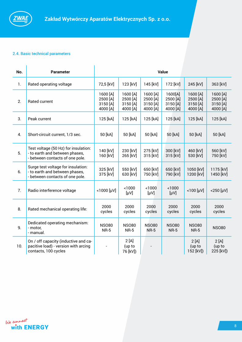
2.4. Basic technical parameters
No. Parameter Value
1. Rated operating voltage 72,5 [kV] 123 [kV] 145 [kV] 172 [kV] 245 [kV] 363 [kV]
2. Rated current
1600 [A]2500 [A]3150 [A]4000 [A]
1600 [A]2500 [A]3150 [A]4000 [A]
1600 [A]2500 [A]3150 [A]4000 [A]
1600[A]2500 [A]3150 [A]4000 [A]
1600 [A]2500 [A]3150 [A]4000 [A]
1600 [A]2500 [A]3150 [A]4000 [A]
3. Peak current 125 [kA] 125 [kA] 125 [kA] 125 [kA] 125 [kA] 125 [kA]
4. Short-circuit current, 1/3 sec. 50 [kA] 50 [kA] 50 [kA] 50 [kA] 50 [kA] 50 [kA]
5.Test voltage (50 Hz) for insulation:- to earth and between phases,- between contacts of one pole.
140 [kV]160 [kV]
230 [kV]265 [kV]
275 [kV]315 [kV]
300 [kV]315 [kV]
460 [kV]530 [kV]
560 [kV]750 [kV]
6.Surge test voltage for insulation:- to earth and between phases,- between contacts of one pole.
325 [kV]375 [kV]
550 [kV]630 [kV]
650 [kV]750 [kV]
650 [kV]790 [kV]
1050 [kV]1200 [kV]
1175 [kV]1450 [kV]
7. Radio interference voltage <1000 [µV] <1000 [µV]
<1000 [µV]
<1000 [µV] <100 [µV] <250 [µV]
8. Rated mechanical operating life: 2000 cycles
2000 cycles
2000 cycles
2000 cycles
2000 cycles
2000 cycles
9.Dedicated operating mechanism:- motor,- manual.
NSO80NR-5
NSO80NR-5
NSO80NR-5
NSO80 NR-5
NSO80NR-5 NSO80
10. On / off capacity (inductive and ca-pacitive load) - version with arcing contacts, 100 cycles
-2 [A]
(up to 76 [kV])
-2 [A]
(up to 152 [kV])
2 [A] (up to
225 [kV])

Zakład Wytwórczy Aparatów Elektrycznych Sp. z o.o.
9
3. INSTALLATION AND ADJUSTMENTThe delivered disconnector is completely regulated and ready to work. Installation is reduced to:a) installing poles on a supporting structure,b) attaching supporting constructions for the operating mechanisms,c) installing of operating mechanisms,d) poles coupling and its regulation,e) earthing switches coupling,f) earthing switches regulation,g) grounding the base frame and the operating mechanism.
3.1. Preparing contact surfacesThe contact resistance of touching each other elements depends primarily on the quality and cleanliness of the contacting surfaces. These surfaces should be very precisely prepared. The method of preparing alumini-um and silver contact surfaces is described below:
• aluminium – aluminium connectionthe oxide layer from the contact surface should be removed by using a wire brush. After this treatment, the sur-face should be matt gray, devoid of shiny areas. Any chips and aluminum dust should be thoroughly removed from the surface, eg by lubricating with acid-free grease and then removing it. After this treatment, the surface should be greased with acid-free grease to protect it from oxidation of aluminum. The prepared surface should not be exposed to the atmosphere longer than the time needed to prepare the cooperating surface.
• Copper – silver connectionThe copper surfaces should be cleaned of oxides by using a brass wire brush and then should be proceeded as for the aluminum surface. Silver surfaces do not need to be cleaned with a brush, but they can be cleaned with a delicate abrasive material, eg steel wool. After cleaning the surface should be covered with a thin layer of acid-free grease.
Zakład Wytwórczy Aparatów Elektrycznych Sp. z o.o.
10
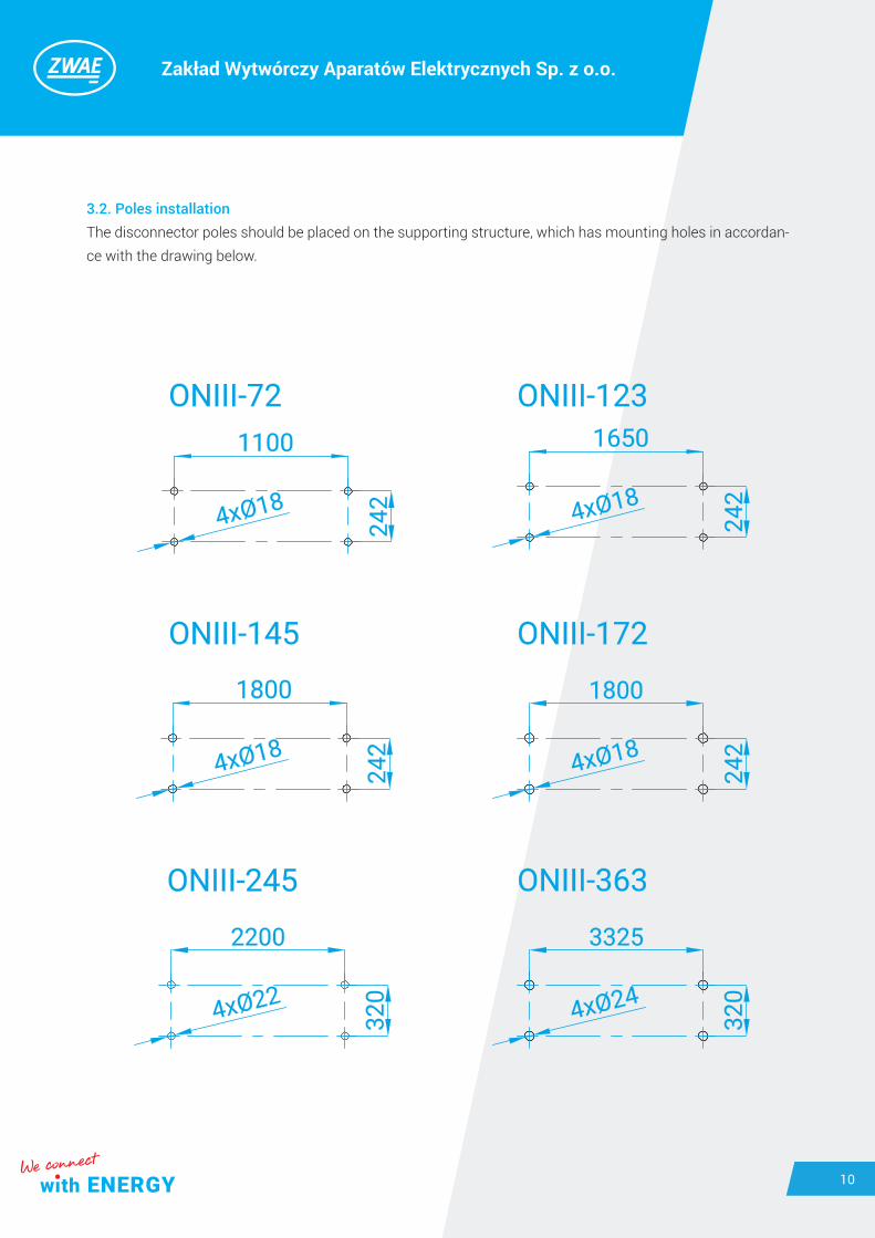
3.2. Poles installationThe disconnector poles should be placed on the supporting structure, which has mounting holes in accordan-ce with the drawing below.
Zakład Wytwórczy Aparatów Elektrycznych Sp. z o.o.
11
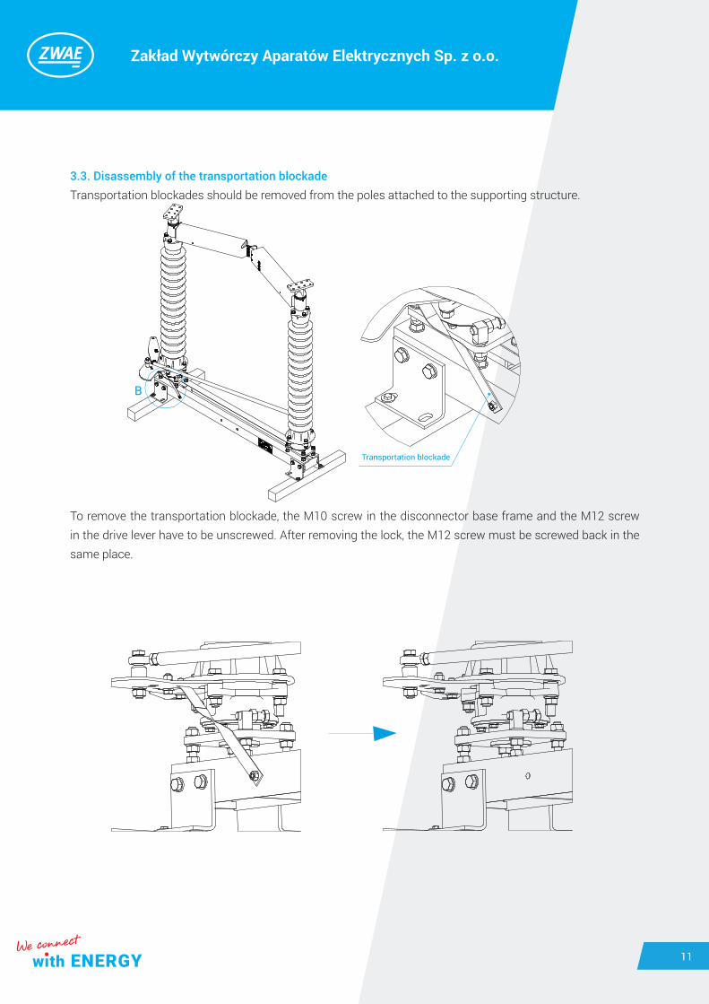
3.3. Disassembly of the transportation blockadeTransportation blockades should be removed from the poles attached to the supporting structure.
To remove the transportation blockade, the M10 screw in the disconnector base frame and the M12 screw in the drive lever have to be unscrewed. After removing the lock, the M12 screw must be screwed back in the same place.
Transportation blockade
Zakład Wytwórczy Aparatów Elektrycznych Sp. z o.o.
12
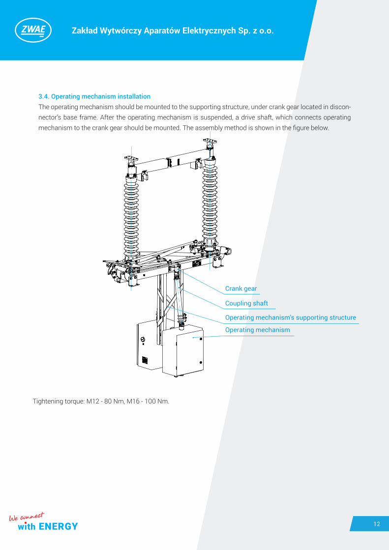
3.4. Operating mechanism installationThe operating mechanism should be mounted to the supporting structure, under crank gear located in discon-nector’s base frame. After the operating mechanism is suspended, a drive shaft, which connects operating mechanism to the crank gear should be mounted. The assembly method is shown in the figure below.
Crank gear
Coupling shaft
Operating mechanism's supporting structure
Operating mechanism
Tightening torque: M12 - 80 Nm, M16 - 100 Nm.

Zakład Wytwórczy Aparatów Elektrycznych Sp. z o.o.
13
3.5. Pole coupling and adjustmentAfter setting the poles on the supporting structure, one should check the limit positions of the current paths and, if necessary, correct the position of the bumpers and the lengths of the coupling tie rods of the discon-nector’s kinematic system. After checking the correctness of operation of the poles the coupling rods can be assembled.
Tightening torque of M16 screws - 100 Nm.
Current path position adjustment screws
Current path rotation angle limit bumper
Coupling tie rod

Zakład Wytwórczy Aparatów Elektrycznych Sp. z o.o.
14
Poles coupling regulation lies in such a setting of the length of the tie rod and coupling lever location adjust-ment so that the current paths at each pole reach the limit positions according to the following requirements.
Regulation process should be performed in following way:a) initially coupling tie rods should be installed in such a way that one pole would not be connected (tie rod ending hang on a line, below coupling lever),b) coupling tie rod should be extended or shortened in such a way that current path in driving pole would achieve require limit positions. If tie rod length change forecloses achievement of the limit positions driving lever position should be changed on driving pole. The next figure presents the behavior of the disconnector’s poles when changing the position of the drive lever while maintening the same length of tie rod. After changing the position of the lever it is necessary to correct the length of the tie rod and check the limit positions of the current path. c) after finishing one pole’s coupling regulation it is permitted to tighten up tie rod to the last pole and repeat steps from subpoint b.
Typ A B C D E
ONIII-72 1300 900 632 710 798
ONIII-123 1900 1450 1020 1090 1320
ONIII-145 2100 1600 1160 1365 1498
ONIII-172 2500 1600 1560 1365 1498
ONIII-245 3500 2295 2090 2100 1960
ONIII-363 5000 3420 2920 2700 3310

Zakład Wytwórczy Aparatów Elektrycznych Sp. z o.o.
15
Regulation lever – Left position. Regulation lever – Right position. Regulation lever – Neutral position.

Zakład Wytwórczy Aparatów Elektrycznych Sp. z o.o.
16
3.6. Earthing switches couplingEarthing switches have to be coupled using coupling shafts, which lenght is presented in the table below.
Left earthing switch shaft
Right earthing switch shaft
Type
Application
Disconnector’s and earthing switches driving
shaft
Coupling shaft – left earthing switch
Coupling shaft – right earthing switch
ONIII-72 A = 615 A = 700 A = 765
ONIII-123 A = 615 A = 1300 A = 1360
ONIII-145 A = 615 A = 1500 A = 1560
ONIII-172 A=615 A=1500 A=1560
ONIII-245 A = 750 A = 2777 A = 2855
ONIII-363 A = 750 A = 4277 A = 4355

Zakład Wytwórczy Aparatów Elektrycznych Sp. z o.o.
17
In lower end position, the earthing blade's ending can not be located over insulators coupling tie rod. (Apply to ONIII-72 and ONIII-123)
3.7. Earthing switches operating regulationEarthing switches regulation lies in such setting of coupling shafts that earthing knives on each pole should achieve limit positions in accordance with requirements presented in the drawing below and earthing circuit closing occur simultaneously.
On earthing switches coupling shaft should be set earthing switch’s locking, in order to enable earthing switch to work only with open disconnector. Figure below shows way of fit-ting of the locking.
Contacts points of contacts location

Zakład Wytwórczy Aparatów Elektrycznych Sp. z o.o.
18
3.8. Grounding of the base framesAfter disconnector’s and earthing switches regulation, apparatus base frames have to be grounded. Earthing terminals are marked on disconnector’s base frame. In case of grounding of disconnector with built- up ear-thing switch, an earthing wire should be connected as close as possible to line linking earthing switch knife with base frame. Terminals location is presented in figure below.

Zakład Wytwórczy Aparatów Elektrycznych Sp. z o.o.
19
4. OPERATING MANUALDisconnector’s switching is achieved by using an appropriate motor or manual operating mechanisms.
4.1. Notes about connecting activitiesa) While disconnector’s or its earthing switch’s manoeuvring all safety at work rules applicable in installation’s location should be respected.b) Energized disconnector can be manoeuvred only when capacity of intermittent current will have negligible value or any significant voltage change between any pole’s contact elements would not appear. Disconnector equipped with commutating contacts is ready to switch off currents specified in technical data.c) The disconnector must not be closed until its earthing switch has been opened.d) Disconnector’s earthing switch can be manoeuvred from open to close position only:• If the disconnector is in open position, • After ensuring that earthing switch will be working under discharging current of the bushings, rails, incoming supplies, short cables and power lines capacities, with current and voltage parameters specified in technical data.
5. INSPECTIONS AND MAINTENANCE
5.1. Visual inspections It is recommended to carry out visual inspections in accordance with rules being in force in switchgear or after each failure or short circuit. Check in particular:
a) condition of current path’s central contacts,b) condition of earthing switch’s contacts.
5.2. Periodic check-ups In order to ensure continuous and failure-free operation of the disconnector, it is necessary to perform periodic check-ups. While the internal regulations in force in the distribution centre do not oblige to more frequent main-tenance, inspections are required in accordance with the following schedule:• Periodic inspection - after 5 years of operation or after 1000 operation cycles;• General inspection - after 10 years of operation or after 2000 operation cycles.
During inspection and maintenance, the applicable regulations for the operation of energy devices and the requirements determining the safety of work of the inspectors must be obeyed.

Zakład Wytwórczy Aparatów Elektrycznych Sp. z o.o.
20
The scope of activities to be performed during each maintenance is as follows:
a) Periodic inspection: • check the condition of the current path contacts;• check the condition of the earthing switch contacts;• check the correctness of taking the end positions;• check the condition of mechanisms and bearings;• check tightness of screw connections and fasteners;• clean the outer surfaces of insulators;• check the condition of protective coatings and parts protecting against corrosion;• lubricate the current path contacts and the earthing switch contacts (not required for disconnectors equipped with graphite AgC contacts) 1);• perform thermal inspection of the disconnector at rated current 2).
b) General inspection:• perform the complete set of activities described above for the periodic inspection;• clean all moving parts;• measure the voltage drop of the disconnector’s main circuits at currentI = 100A DC 3);• check dimensional compliance of the disconnector with the dimensional drawing, in particular insulation gaps and spaces between live parts;• check the condition of anti-interference screens (if installed);• check technical condition of insulators 4);• check the operation and condition of arcing contacts (if installed) 5);• check earthing of the disconnector bases.
When assessing condition of the disconnector’s contacts, check if the silver coating on the contact surfaces has not been permanently damaged. If necessary, replace damaged contacts with new ones.
2) In case of thermal imaging tests, the permissible temperature values given in Table 14 of the PN-EN 62271-1: 2018-02 standard should be adopted as a criterion for assessing the correct operation of the disconnector.
3) In case of measuring the voltage drop of the main circuits of a disconnector not connected to the busbar system, the acceptable values indicated in the factory test report of the finished product should be taken as the criterion for assessing the correct operation of the disconnector. In the case of a disconnector connected to the busbar system, the voltage drop should not exceed 250 µΩ.
4) When assessing the condition of insulators, it is necessary to check if there are no losses or damage to the insulators, with particular emphasis on the surface of the shade. If necessary, replace damaged insulators with new ones.

Zakład Wytwórczy Aparatów Elektrycznych Sp. z o.o.Gdańska 60, 84-300 LęborkPOLAND
Correspondence addressKębłowo Nowowiejskie, ul. Łąkowa 284-351 Nowa Wieś LęborskaPOLAND
[email protected].: +48 59 863 36 15
www.zwae.com.pl
Zakład Wytwórczy Aparatów Elektrycznych Sp. z o.o.
5) When assessing the condition of the apparatus’ arcing contacts, it is necessary to check whether there are no cavities or pits on the contact surfaces. If necessary, replace damaged contacts with new ones.
5.3. Spare parts and recommended service materialsThe use of high quality components and operational experience indicate long live service of disconnectors (not less than 40 years). If the disconnector is damaged due to improper assembly or operation, it is possible for the manufacturer to repair it for a fee. Disconnector type ONIII does not possess any parts, which should be replaced during normal operation in service life.
For disconnectors maintenance, materials listed below have to be used:
a) WHITE PHARMACEUTICAL PETROLEUM JELLY (acid-free) used for lubrication electric contacts (earthings, contacts of HV switches),b) LUBRICANT for bearings, for example LT4 or similar, used for lubricating ball joints.
6. UTILIZATION
The ONIII disconnectors are made of materials that are recyclable.The main materials from which the disconnectors are built are:• steel (hot-dip galvanized);• aluminum;• copper.
The disconnectors do not contain any dangerous substances. In accordance with applicable regulations, it is possible to return a worn-out, complete disconnector to the manufacturer.