homogenous charge combustion ignition
TRANSCRIPT

HOMOGENOUS CHARGE COMBUSTION IGNITION
Cesario Mendez
HOW THE TYPICAL ENGINE WORKS Pulls air and fuel into the cylinder Closes the cylinder and compresses the air
and fuel mixture to around 150 psi at “top dead center”.
A spark plug ignites the pressurized mixture which causes a small explosion to push down on a piston turning the crankshaft.
The remaining CO2 gases exit through the exhaust and the cycle repeats.
CONCEPT: WHAT IS HCCI? HCCI stands for Homogenous Charge Combustion
Ignition and how this works is when you heat a fuel air mixture in a chamber to a certain temperature it will auto-ignite. This process is similar to the “knocking” of an engine. The difference between knocking and HCCI is the rate of energy release. Knocking is more spontaneous and has a higher peak pressure in a Pressure vs. Volume diagram. HCCI has a slower and more controlled auto ignition.

GOAL Successfully convert a standard
gasoline operated engine to work with Compressed natural gas.
Transition the engine to operate with compressed natural gas without the aid of a spark plug i.e. auto-combustion.

CONCEPT Lower the U.S dependency of oil products
from foreign countries Natural Gas Abundance Cut loses to make natural gas cheaper than
it already is Put power plant in car Power plants already use natural gas t o
power generators that supply electricity Modeling

HARDWARE DEVELOPMENTEngineIntakeTest Bench (Cage , Dynamometer, Engine
installation etc.) EGR

INSTRUMENTATION Air flow meter Thermocouples Pressure transducer Encoder Dampener

AIR FLOW METER Air Flow Meter: Used to find the flow
rate of the air that is going into the intake system after the flow Straightener

THERMOCOUPLES Monitor the temperatures of all
different parts of the engine. They are places on
Exhaust ports, The intake manifold, Measure oil tem through dipstick,
ambient air temp, Intake air temp

PRESSURE TRANSDUCER Monitors the pressures during the
combustion process in the chamber to create a PV diagram
ENCODER Reads out all the crank angles and
rpm’s of the engine to the third decimal place. With the encoder we can tell exactly where the piston in the chamber.

DAMPENER Being that this engine is a V twin there
are a lot of pressure pulsations coming through the intake system. The dampener resonates the pulsations over a larger area.

EGR (EXHAUST GAS RECIRCULATION) Re-circulating exhaust gas back into
the intake manifold then mixing it with fresh air and fuel steadies the rate of release during auto ignition.

WHAT WE ACCOMPLISHEDOver the course of the last 2 months we
have successfully instrumented the engine debugged it and everything is now currently operational, with all sensors, meters working, the engine is running smoothly and our software is showing reading accurate readings.
DIFFICULTIES Working in an engine that has many sensors and
meters attached to it is a very difficult task because things have to be constantly changed, takes off, drilled, welded, machined, dimensioned etc. With a group of 8 people, in the beginning it was a shoving match of elbows and tools.
Ordering parts gave us a great deal of difficulty because they were either high precision parts that can not be bought in store or communication issues between departments.

MODELING AND FLUENT ANALYSIS
Theoretical Properties of an NGE
combustion chamber Intake and Exhaust
valves are closed Looking at different
stages of piston Air compressed inside
the chamber

STEP PROCESS Step 1. Compression of air in closed chamber Provided some insight into modeling.
Step 2. Compression of methane and air closed chamber This will provide information on mixture interaction during compression.
Step 3. Develop thermal model (temperature distribution on walls and volume) for methane/air mixture along with pressure and temperature.
Very important step as will provide information on our computing capabilities and temperature distribution within the chamber (hot spots)
Step 4. Redo the step 3 with EGR and heated air as inputs. This will change all the dynamics of the modeling that we will have done thus far and
will require high computing power.
Step 5. Use thermal model from step 4 as initial conditions and run the simulation again. The final step before combustion modeling. Results will give some approximation on
developing HCCI combustion.
MODELING Achievements Worked with
previous team member’s parts
Model Head Piston Gasket Cylinder
Future Converting UG files
to Solid works files Add missing material
to detailed model
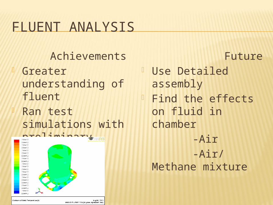
FLUENT ANALYSIS Achievements Greater
understanding of fluent
Ran test simulations with preliminary assembly
Future Use Detailed
assembly Find the effects on
fluid in chamber -Air -Air/ Methane
mixture