homemade electric hydrofoil e-foil (hiorth)
TRANSCRIPT

instructables
Homemade ELECTRIC Hydrofoil E-foil (Hiorth)
by sabladask
We decided to share our progress on building anelectrical hydrofoil. Here you will find our V1 design,part list and 3d files.
We want to make it easier for everyone to build theirown, as its a lot of fun building and riding :), and thatis why we are sharing our progress. We will split theinstructable in two parts. Part 1 (board, hydrofoil andpropulsion unit) and part 2 (battery and controller)which is still under development. We will show thebattery and controller setup for the first prototype, but
more pictures at. https://www.facebook.com/nikolai.hiorth/media_set?...
The main components:
Part 1:
//www.youtube.com/embed/72JACM-3Hls
Homemade ELECTRIC Hydrofoil E-foil (Hiorth): Page 1

we do not recommend it because of fire hazard andthere is no safety features implemented, do at yourown risk!. We will post Part 2 with a more thoroughbuilt battery and controller unit with included safetyfeatures once developed.
The video is from the first day testing.
//www.youtube.com/embed/oPcYad5fXiU
//www.youtube.com/embed/C0laEi8YHUU
Part 1:
Board
Hydrofoil
propulsion unit
Part 2
Battery
Controller.
Homemade ELECTRIC Hydrofoil E-foil (Hiorth): Page 2

Homemade ELECTRIC Hydrofoil E-foil (Hiorth): Page 3

https://youtu.be/jajsR_gye88
https://www.youtube.com/watch?v=z_CzsT2U8W0&feature=youtu.be
https://www.youtube.com/watch?v=C0laEi8YHUU
https://www.instructables.com/ORIG/FI0/YONP/J9SVNBO5/FI0YONPJ9SVNBO5.mp4…Download
Step 1: What Parts Do You Need?
Hydrofoil,
Can be bought, or made custom. In this case thehydrofoil is bought from a supplier.
Propulsion unit
Standard part: Motor, Gearbox Aluminium tube,bearings, shaft seals, shaft + nuts and bolts
Custom parts: Motor mount, propeller, duct andstructural components (3d printed)
Control unit --> PART 2
A more detailed instruction will come.
Battery pack --> PART 2
A more detailed instruction will come.
Part list.
The part list includes the most important components.But does not include everything.
Homemade ELECTRIC Hydrofoil E-foil (Hiorth): Page 4

https://www.instructables.com/ORIG/FAN/ORXH/J6IF1AKR/FANORXHJ6IF1AKR.xlsx…Download
https://www.instructables.com/ORIG/FT6/9JY0/J7MFFSCI/FT69JY0J7MFFSCI.pdf…Download
Step 2: Hydrofoil
Originally we were planning to build over own. But tosave time we bought a new one (NOBILE). We thinka SUP hydrofoil might be better, as they have a largerfront wing which will give more lift at lower speeds.
Having a hydrofoil with detachable wings Is highlyrecommended, it makes it very easy to trim the angleof attack by adding washers. Especially changing theangle of the rear wing is important to get a smoothride. It also helps to make the board more compact
during transportation.
Our 3d parts are made for the Nobile foil Mast. Butthey can easily be changed to fit other types of mast,as long as you know the cross section of your mast.
The Nobile mast we bought is 85mm long, and thefront wing is the largest type.
Homemade ELECTRIC Hydrofoil E-foil (Hiorth): Page 5

Step 3: Propulsion Unit (Thruster) Overview
The thruster consist of a motor, gearbox, propeller,duct and housing. The gearbox reduces the RPM ofthe motor by 5:1 thereby increasing the torque andallowing a larger propeller --> higher efficiency.
The majority of the structural components are 3dprinted, in SLS nylon (super strong and watertight)
and FDM PLA (not that strong).
The gearbox and motor assembly is glued inside analuminium tube with epoxy, so it is not possible todisassemble. So take extra precaution and use stronglocktite when putting these parts together.
Homemade ELECTRIC Hydrofoil E-foil (Hiorth): Page 6

Step 4: Propulsion Unit 3D Print
The Propulsion unit have structural parts made fromSLS nylon and FDM pla.
SLS Nylon is thin layers of powder that are meltedtogether with a laser layer by layer. A thin layer on thesurface is porous, which makes it ideal for liquidepoxy gluing without any prepping, as the epoxy ispulled inside the outer layer of the part making astrong bond. Epoxy or grease can also be used toseal the porous surface of the part, such as in O-ringgroves (We would recommend grease for this). If theparts are sanded, the porous layer will be removed,and a solid surface appear, this surface is harder tobond with epoxy.
We ordered the SLS nylon parts from 3Dprint-UK. https://www.3dprint-uk.co.uk/
Specify that you want a mesh structure inside the
parts, or they will print solid sections greater than8mm with 4mm walls. Total solid parts needs to bespecified.
The duct and Prop was printed on our own FDMprinter in PLA (wanhao i3 plus), to allow optimizingchanges. You might think that a PLA prop wouldbreak, but is actually really rigid. There is no sign todamage on our prop or duct, which we have used onseveral tests already. We tested with ABS as well,but we would say that PLA is better, as the finaldimensions of solid parts are more accurate than withABS.
The propeller, duct and structural components areincluded. Note that the shaft, and motor mount mustbe custom made, based on your gearbox/motorsetup.
Homemade ELECTRIC Hydrofoil E-foil (Hiorth): Page 7

https://www.instructables.com/ORIG/FGM/ZQ9E/J6IF23ZT/FGMZQ9EJ6IF23ZT.step…Download
https://www.instructables.com/ORIG/FHC/MYNF/J6IF2416/FHCMYNFJ6IF2416.stl…DownloadView in 3D
https://www.instructables.com/ORIG/F2P/HQSU/J6IF244P/F2PHQSUJ6IF244P.stl…Download
https://www.instructables.com/ORIG/F9M/KZM9/J6IF244S/F9MKZM9J6IF244S.step…Download
https://www.instructables.com/ORIG/FUH/KI34/J6IF2475/FUHKI34J6IF2475.stl…DownloadView in 3D
https://www.instructables.com/ORIG/FFU/LI1E/J6IF2476/FFULI1EJ6IF2476.step…Download
Homemade ELECTRIC Hydrofoil E-foil (Hiorth): Page 8

Step 5: Propeller and Duct Design Considerations
An optimal propeller and duct may greatly increasethe efficiency. There are however several factor thatmus be taken into account:
- Propeller size--> bigger is better, but bigger maymake it harder to ride. (as the propeller may reach thesurface)
- Propeller pitch, blade area, sweep and so on.. Thereare many!! parameters that can be optimized
- Duct design, improves safety and may also greatlyimproves thrust at low speeds
- Safety, small propeller is "safer" as its harder toplace your fingers/toes inside
The ducts main purpose is to protect body parts fromentering the propeller, and increase thrust. We usedan airfoil profile (NACA 6721, AOA 5 degrees) toincrease the propeller efficiency at speeds up toabout 15knots (which is proven to be efficient for
large ships). Notice the twisted foil stators (“arms”holding the duct) they rotate the water stream prior tothe propeller, the propeller rotates the water in theopposite direction, the result is less rotational energyloss to the water downstream of the propeller andthereby increasing its efficiency. Our next iteration ofthe duct will include twisted stators down-stream ofthe propeller, to further increase safety.
The propeller is optimized for 3d printing. The pitchblade area and sweep is not calculated, but it workswell with our setup. The propeller cross section isnow a B-troost, which is good for forward motion.Note that the distance between the propeller tip andduct is tight, this improves efficiency!.
We will try to do some calculations and/or CFDanalyses to figure out the optimal shape of propellerand duct, this can give Lots of extra speed and longerrides!. But this is something we will do once we haveeverything up and running.
Homemade ELECTRIC Hydrofoil E-foil (Hiorth): Page 9
Step 6: Propulsion Unit Assembly
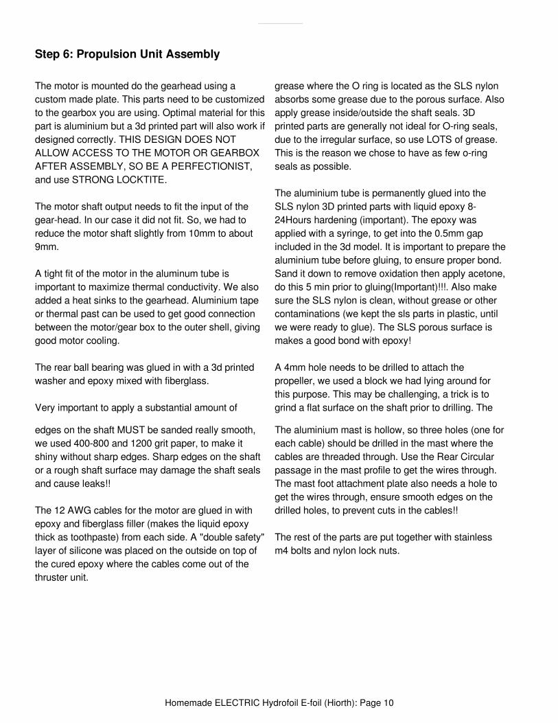
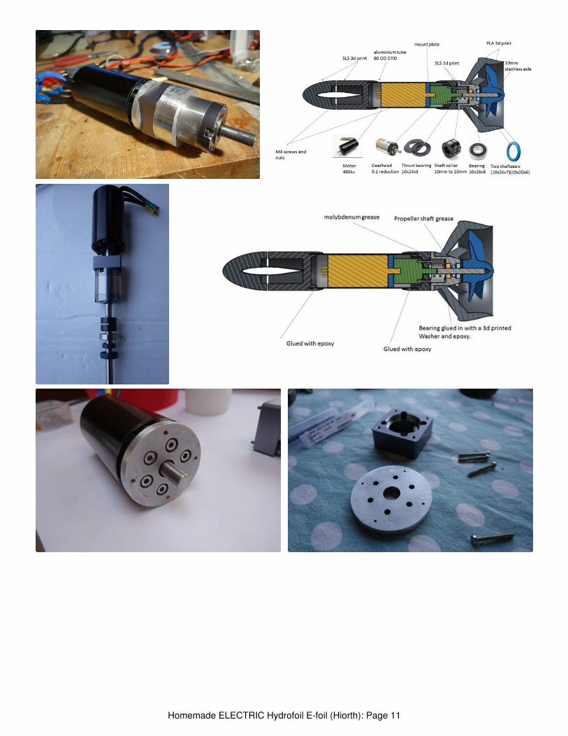
The motor is mounted do the gearhead using acustom made plate. This parts need to be customizedto the gearbox you are using. Optimal material for thispart is aluminium but a 3d printed part will also work ifdesigned correctly. THIS DESIGN DOES NOTALLOW ACCESS TO THE MOTOR OR GEARBOXAFTER ASSEMBLY, SO BE A PERFECTIONIST,and use STRONG LOCKTITE.
The motor shaft output needs to fit the input of thegear-head. In our case it did not fit. So, we had toreduce the motor shaft slightly from 10mm to about9mm.
A tight fit of the motor in the aluminum tube isimportant to maximize thermal conductivity. We alsoadded a heat sinks to the gearhead. Aluminium tapeor thermal past can be used to get good connectionbetween the motor/gear box to the outer shell, givinggood motor cooling.
The rear ball bearing was glued in with a 3d printedwasher and epoxy mixed with fiberglass.
Very important to apply a substantial amount of
grease where the O ring is located as the SLS nylonabsorbs some grease due to the porous surface. Alsoapply grease inside/outside the shaft seals. 3Dprinted parts are generally not ideal for O-ring seals,due to the irregular surface, so use LOTS of grease.This is the reason we chose to have as few o-ringseals as possible.
The aluminium tube is permanently glued into theSLS nylon 3D printed parts with liquid epoxy 8-24Hours hardening (important). The epoxy wasapplied with a syringe, to get into the 0.5mm gapincluded in the 3d model. It is important to prepare thealuminium tube before gluing, to ensure proper bond.Sand it down to remove oxidation then apply acetone,do this 5 min prior to gluing(Important)!!!. Also makesure the SLS nylon is clean, without grease or othercontaminations (we kept the sls parts in plastic, untilwe were ready to glue). The SLS porous surface ismakes a good bond with epoxy!
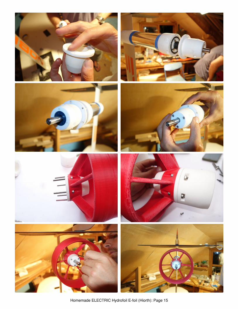
A 4mm hole needs to be drilled to attach thepropeller, we used a block we had lying around forthis purpose. This may be challenging, a trick is togrind a flat surface on the shaft prior to drilling. The
edges on the shaft MUST be sanded really smooth,we used 400-800 and 1200 grit paper, to make itshiny without sharp edges. Sharp edges on the shaftor a rough shaft surface may damage the shaft sealsand cause leaks!!
The 12 AWG cables for the motor are glued in withepoxy and fiberglass filler (makes the liquid epoxythick as toothpaste) from each side. A "double safety"layer of silicone was placed on the outside on top ofthe cured epoxy where the cables come out of thethruster unit.
The aluminium mast is hollow, so three holes (one foreach cable) should be drilled in the mast where thecables are threaded through. Use the Rear Circularpassage in the mast profile to get the wires through.The mast foot attachment plate also needs a hole toget the wires through, ensure smooth edges on thedrilled holes, to prevent cuts in the cables!!
The rest of the parts are put together with stainlessm4 bolts and nylon lock nuts.
Homemade ELECTRIC Hydrofoil E-foil (Hiorth): Page 10
Homemade ELECTRIC Hydrofoil E-foil (Hiorth): Page 11

Homemade ELECTRIC Hydrofoil E-foil (Hiorth): Page 12

Homemade ELECTRIC Hydrofoil E-foil (Hiorth): Page 13

Homemade ELECTRIC Hydrofoil E-foil (Hiorth): Page 14
Homemade ELECTRIC Hydrofoil E-foil (Hiorth): Page 15
https://www.youtube.com/watch?v=Vvb6NUnNSm8
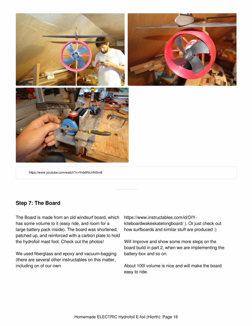
Step 7: The Board
The Board is made from an old windsurf board, whichhas some volume to it (easy ride, and room for alarge battery pack inside). The board was shortened,patched up, and reinforced with a carbon plate to holdthe hydrofoil mast foot. Check out the photos!
We used fiberglass and epoxy and vacuum-bagging(there are several other instructables on this matter,including on of our own
https://www.instructables.com/id/DIY-kiteboardwakeskatelongboard/ ). Or just check outhow surfboards and similar stuff are produced :)
Will Improve and show some more steps on theboard build in part 2, when we are implementing thebattery-box and so on.
About 100l volume is nice and will make the boardeasy to ride.
Homemade ELECTRIC Hydrofoil E-foil (Hiorth): Page 16

Homemade ELECTRIC Hydrofoil E-foil (Hiorth): Page 17

Homemade ELECTRIC Hydrofoil E-foil (Hiorth): Page 18
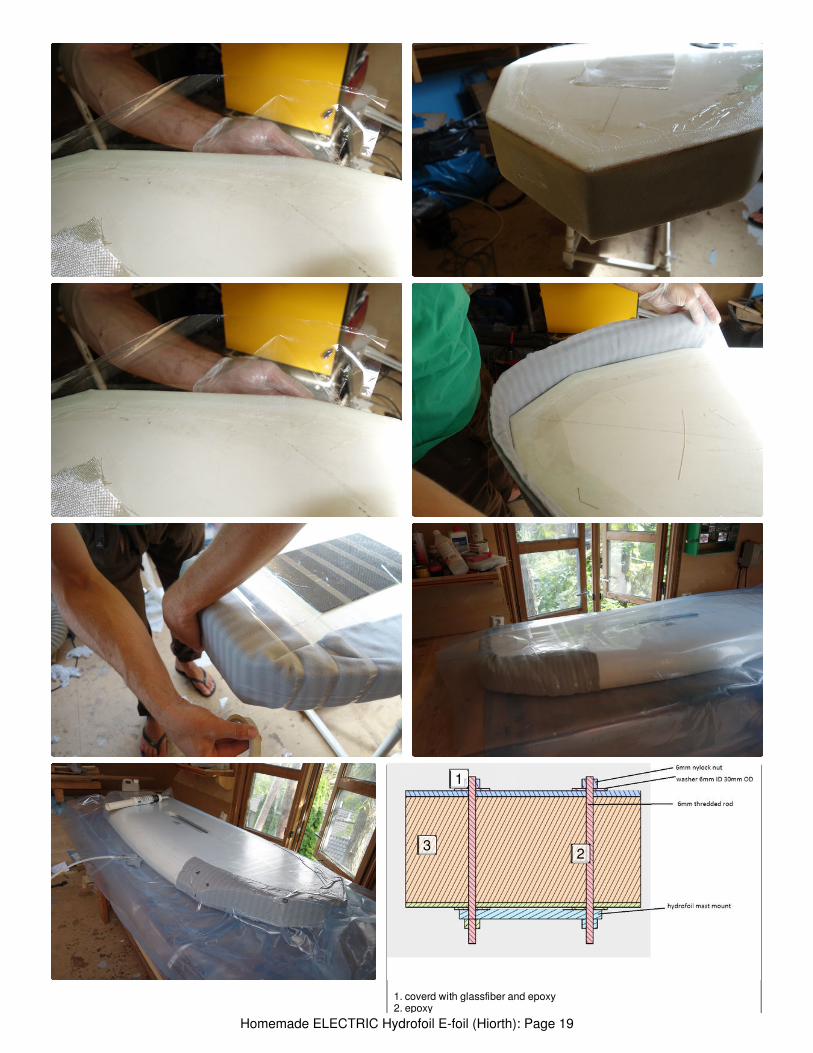
1. coverd with glassfiber and epoxy2. epoxy
1
23
Homemade ELECTRIC Hydrofoil E-foil (Hiorth): Page 19

2. epoxy
3. core of board
Homemade ELECTRIC Hydrofoil E-foil (Hiorth): Page 20

Step 8: Battery and Controller Unit (Dangerous Prototype, Not Recommended!!!).
The batterypack consists of 2x 6s 5000mah battery’s.running in series. Total 12s. we also tried with a 8sbattery. it works with 8s but we want more power!
2x 6s battery’s gives us about 10min ride time.
This version has no water-cooling so the ESC getsvery hot. As of now we are building a bigger batterywith about 1.5-2kwh capacity. It should give us 1-hourride time. We recommend using an aluminum ( box
due to easy heat transfer. The controller has nowaterproofing. We had it in a plastic bag each timewe used it.
Battery pack and controller will be greatly improvedfor next version.
Stay tuned for next PART 2.
Homemade ELECTRIC Hydrofoil E-foil (Hiorth): Page 21
awsome :)
Hello,Do you have files concerning the machining of the V2?Thank youManu
Do you sell this kit? Could you ship to Brazil?
Thank you for sharing 3D files!! Great help. And all the pictures and instruction! Already started theproject.
nice build! alsosame colors that’s awesome. Did you get SLS print for the White parts aswell?
nice!
How many motor rpm?
Good days guys,
I love your project so much... I have already printed Pacificm... parts, I have the metal tube, sameSSS motor etc... but your parts here look slightly different, and for some reasons I think that theSTL assembly and structural pieces you uploaded are not accepted by Solidworks. Also, structuralparts set-up also does not show up correctly in 3D on Chrome (front part position in the placed inthe middle of the assembly, etc...) Do you think that you could upload the STEP version of each ofthose structural parts please ? Many thanks. Philippe
Step 9:
Homemade ELECTRIC Hydrofoil E-foil (Hiorth): Page 22

Hi Guys! i really like your project it's amazing and i'm looking do build one by myself !! I just want toknow if you got all the informatin for the new propeller, duct and also the new improvement you didon your project.
yes, we know alot more now been building since this instructable. if i get the time i will post mordrawings and designs, including remote.
thx about 25km/h.
Hi
Thanks for the drawing and the instruction to build this electric hydrofoil.
I wonder if it is possible to get the latest update for the propeller and duct?
I can only use stl file.
my best regards
You guys are doing a great job here ! Thank you very much for sharing all that progress ! I amgoing to try to make my own thruster with your tutorial.
Before making it, I wanted to understand a bit better your design choices in relation withperformances. I wanted to estimate the speed and the thrust that this prop could generate. How didyou get the profile of this prop ? Could you share its caracteristics? I measured roughly the pitchwhich I found of 234mm, and the diameter of 150 mm, but I don't know about the efficiency of thistype of prop. I would need it to find the relationship between Torque and Thrust ?
Could you guys help me on this ? Thanks a lot again for all this work ! Cheers.
We areworking on improving the propeller, we are now on the 3. Iteration propeller/duct.The one posted is 1. Iteration. A test rig is on its way. This way we can measurethrust, rpm and power consumption. Then we will use results combined with computeranalysis to make improvements.
Thank you for this answer !
I wish you good luck with next test.
Great Job!! Thanks a lot for sharing! You mention in your propeller description:https://grabcad.com/library/propeller-hydrofoil-1 ideal prop RPM 1800-2500. But. Your 480kv Motorwith 12s lipo so 480*44,4 reduced by the 1:5 gear is about 4224 rpm, so what rpm do yourecommend for the Prop?
You have totake account that the 440kv rating is under no load. The actual prop speedunder load is within this 1800-2500.
thats very nifty
thnx!
awesome! i'll build one like this. Wondering when you will post 2nd version of your battery pack?
work in progress, probably within 3 months. :)controller is also on the way.
Looks like a nice first iteration. Projects like these can be difficult when you are starting fromscratch, making the system work, and then trying to keep the water out.
What motor are you using? On my electric boat the motors from 12 volt winchs always get quitehot unless I run them at 6 volts. providing much less power.
I am using Ray Vellinga's book on hydrofoils to design my hydrofoil board. Nothing on motorsthere, but great hydrofoil design info.
Homemade ELECTRIC Hydrofoil E-foil (Hiorth): Page 23

The motor spesifications Are provided i the list of materials.
This is looking awesome so far. Can't wait to see the rest :)
Homemade ELECTRIC Hydrofoil E-foil (Hiorth): Page 24