hmt/hdt pneumatic three-way control valve€¦ · no. tt2018-01-0805 hmt/hdt pneumatic three-way...
TRANSCRIPT
NO. TT2018-01-0805
HMT/HDT Pneumatic Three-Way Control Valve
Page � of �1 11
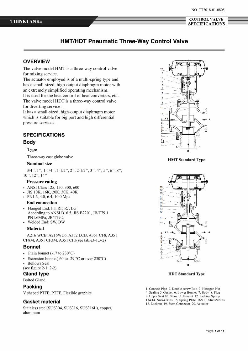
OVERVIEWThe valve model HMT is a three-way control valve for mixing service.The actuator employed is of a multi-spring type and has a small-sized, high-output diaphragm motor with an extremely simplified operating mechanism.It is used for the heat control of heat converters, etc.The valve model HDT is a three-way control valve for diverting service. It has a small-sized, high-output diaphragm motor which is suitable for big port and high differential pressure services.
SPECIFICATIONSBody Type Three-way cast globe valve
Nominal size 3/4’’, 1’’, 1-1/4’’, 1-1/2’’, 2’’, 2-1/2’’, 3’’, 4’’, 5’’, 6’’, 8’’, 10’’, 12’’, 14’’ Pressure rating• ANSI Class 125, 150, 300, 600 • JIS 10K, 16K, 20K, 30K, 40K • PN1.6, 4.0, 6.4, 10.0 Mpa End connection• Flanged End: FF, RF, RJ, LG
According to ANSI B16.5, JIS B2201, JB/T79.1 PN1.6MPa, JB/T79.2
• Welded End: SW, BW Material A216 WCB, A216WC6, A352 LCB, A351 CF8, A351 CF8M, A351 CF3M, A351 CF3(see table3-1,3-2)
Bonnet • Plain bonnet (-17 to 230°C) • Extension bonnet(-60 to -29 ℃ or over 230°C) • Bellows Seal (see figure 2-1, 2-2) Gland typeBolted Gland
PackingV shaped PTFE, PTFE, Flexible graphite
Gasket materialStainless steel(SUS304, SUS316, SUS316L), copper, aluminum
HMT Standard Type
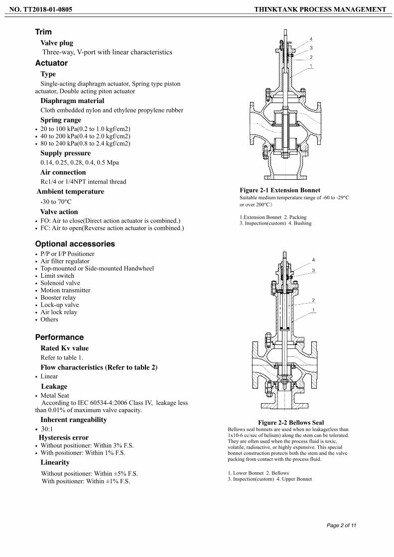
1. Connect Pipe 2. Double-screw Bolt 3. Hexagon Nut 4. Sealing 5. Gasket 6. Lower Bonnet 7. Body 8. Plug 9. Upper Seat 10. Stem 11. Bonnet 12. Packing Spring 13&14. Nuts&Bolts 15. Spring Plate 16&17. Studs&Nuts 18. Locknut 19. Stem Connector 20. Actuator
HDT Standard Type
Page � of �2 11
Trim Valve plug Three-way, V-port with linear characteristics Actuator Type Single-acting diaphragm actuator, Spring type piston actuator, Double acting piton actuator Diaphragm material Cloth embedded nylon and ethylene propylene rubber Spring range• 20 to 100 kPa(0.2 to 1.0 kgf/cm2) • 40 to 200 kPa(0.4 to 2.0 kgf/cm2) • 80 to 240 kPa(0.8 to 2.4 kgf/cm2) Supply pressure 0.14, 0.25, 0.28, 0.4, 0.5 Mpa Air connection Rc1/4 or 1/4NPT internal thread Ambient temperature -30 to 70℃ Valve action• FO: Air to close(Direct action actuator is combined.) • FC: Air to open(Reverse action actuator is combined.)
Optional accessories• P/P or I/P Positioner • Air filter regulator • Top-mounted or Side-mounted Handwheel • Limit switch • Solenoid valve • Motion transmitter • Booster relay • Lock-up valve • Air lock relay • Others
Performance Rated Kv value Refer to table 1. Flow characteristics (Refer to table 2)• Linear Leakage• Metal Seat According to IEC 60534-4:2006 Class IV, leakage less than 0.01% of maximum valve capacity. Inherent rangeability • 30:1 Hysteresis error • Without positioner: Within 3% F.S. • With positioner: Within 1% F.S. Linearity Without positioner: Within ±5% F.S. With positioner: Within ±1% F.S.
Figure 2-1 Extension Bonnet Suitable medium temperature range of -60 to -29℃ or over 200℃)
1.Extension Bonnet 2. Packing 3. Inspection(custom) 4. Bushing
Figure 2-2 Bellows Seal Bellows seal bonnets are used when no leakage(less than 1x10⁻⁶ cc/sec of helium) along the stem can be tolerated. They are often used when the process fluid is toxic, volatile, radioactive, or highly expensive. This special bonnet construction protects both the stem and the valve packing from contact with the process fluid.
1. Lower Bonnet 2. Bellows 3. Inspection(custom) 4. Upper Bonnet
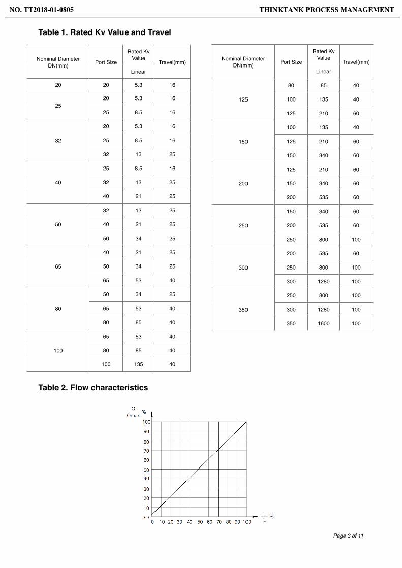
Table 1. Rated Kv Value and Travel
Table 2. Flow characteristics
Page � of �3 11
Nominal Diameter DN(mm) Port Size
Rated Kv Value
Travel(mm)Linear
20 20 5.3 16
2520 5.3 16
25 8.5 16
32
20 5.3 16
25 8.5 16
32 13 25
40
25 8.5 16
32 13 25
40 21 25
50
32 13 25
40 21 25
50 34 25
65
40 21 25
50 34 25
65 53 40
80
50 34 25
65 53 40
80 85 40
100
65 53 40
80 85 40
100 135 40
Nominal Diameter DN(mm) Port Size
Rated Kv Value
Travel(mm)Linear
125
80 85 40
100 135 40
125 210 60
150
100 135 40
125 210 60
150 340 60
200
125 210 60
150 340 60
200 535 60
250
150 340 60
200 535 60
250 800 100
300
200 535 60
250 800 100
300 1280 100
350
250 800 100
300 1280 100
350 1600 100
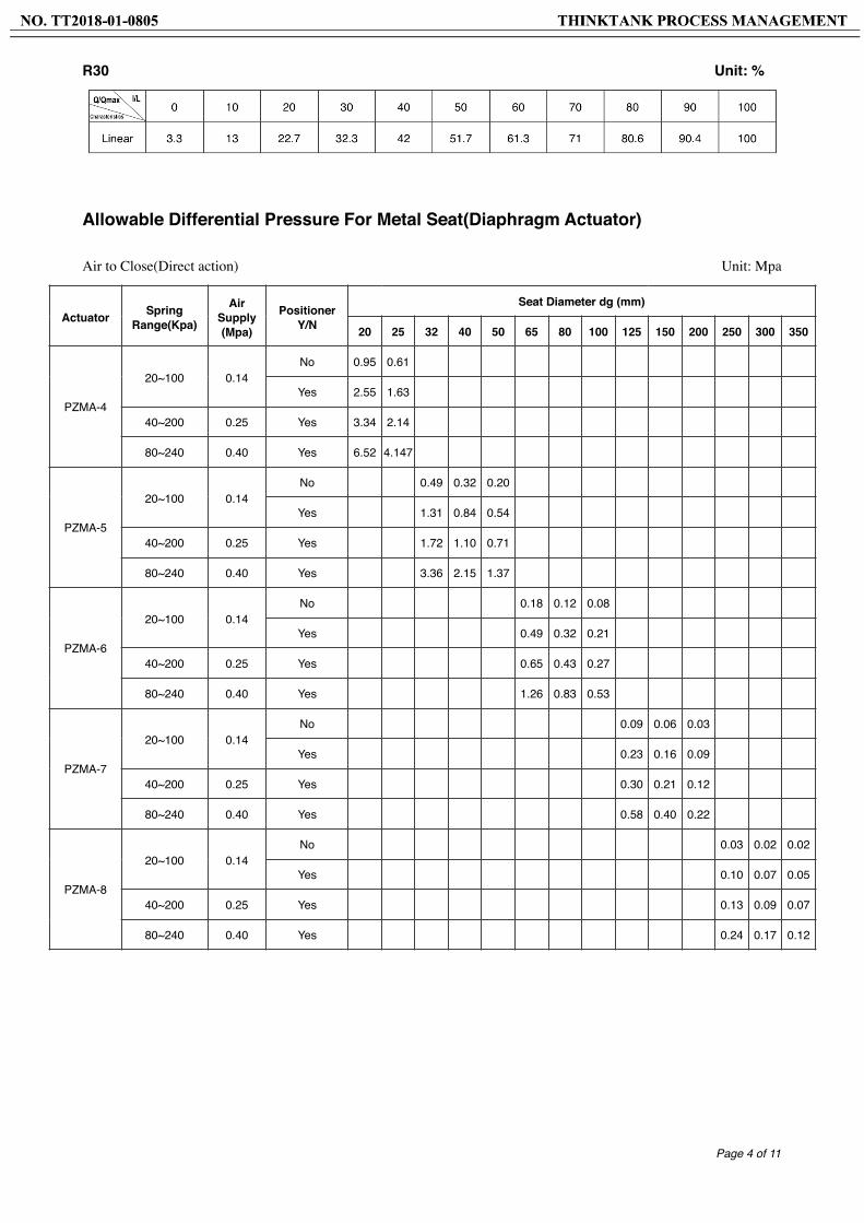
R30 Unit: %
Allowable Differential Pressure For Metal Seat(Diaphragm Actuator)
Air to Close(Direct action) Unit: Mpa
Page � of �4 11
Actuator Spring Range(Kpa)
Air Supply (Mpa)
Positioner Y/N
Seat Diameter dg (mm)
20 25 32 40 50 65 80 100 125 150 200 250 300 350
PZMA-4
20~100 0.14No 0.95 0.61
Yes 2.55 1.63
40~200 0.25 Yes 3.34 2.14
80~240 0.40 Yes 6.52 4.147
PZMA-5
20~100 0.14No 0.49 0.32 0.20
Yes 1.31 0.84 0.54
40~200 0.25 Yes 1.72 1.10 0.71
80~240 0.40 Yes 3.36 2.15 1.37
PZMA-6
20~100 0.14No 0.18 0.12 0.08
Yes 0.49 0.32 0.21
40~200 0.25 Yes 0.65 0.43 0.27
80~240 0.40 Yes 1.26 0.83 0.53
PZMA-7
20~100 0.14No 0.09 0.06 0.03
Yes 0.23 0.16 0.09
40~200 0.25 Yes 0.30 0.21 0.12
80~240 0.40 Yes 0.58 0.40 0.22
PZMA-8
20~100 0.14No 0.03 0.02 0.02
Yes 0.10 0.07 0.05
40~200 0.25 Yes 0.13 0.09 0.07
80~240 0.40 Yes 0.24 0.17 0.12
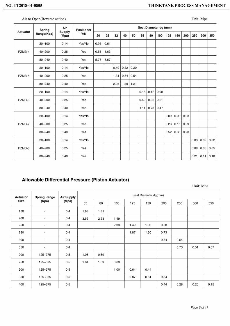
Air to Open(Reverse action) Unit: Mpa
Allowable Differential Pressure (Piston Actuator)Unit: Mpa
Page � of �5 11
Actuator Spring Range(Kpa)
Air Supply (Mpa)
Positioner Y/N
Seat Diameter dg (mm)
20 25 32 40 50 65 80 100 125 150 200 250 300 350
PZMB-4
20~100 0.14 Yes/No 0.95 0.61
40~200 0.25 Yes 0.55 1.63
80~240 0.40 Yes 5.73 3.67
PZMB-5
20~100 0.14 Yes/No 0.49 0.32 0.20
40~200 0.25 Yes 1.31 0.84 0.54
80~240 0.40 Yes 2.95 1.89 1.21
PZMB-6
20~100 0.14 Yes/No 0.18 0.12 0.08
40~200 0.25 Yes 0.49 0.32 0.21
80~240 0.40 Yes 1.11 0.73 0.47
PZMB-7
20~100 0.14 Yes/No 0.09 0.06 0.03
40~200 0.25 Yes 0.23 0.16 0.09
80~240 0.40 Yes 0.52 0.36 0.20
PZMB-8
20~100 0.14 Yes/No 0.03 0.02 0.02
40~200 0.25 Yes 0.09 0.06 0.05
80~240 0.40 Yes 0.21 0.14 0.10
Actuator Size
Spring Range (Kpa)
Air Supply (Mpa)
Seat Diameter dg(mm)
65 80 100 125 150 200 250 300 350
150 - 0.4 1.98 1.31
200 - 0.4 3.53 2.33 1.49
250 - 0.4 2.33 1.49 1.03 0.58
280 - 0.4 1.87 1.30 0.73
300 - 0.4 0.84 0.54
350 - 0.4 0.73 0.51 0.37
200 125~375 0.5 1.05 0.69
250 125~375 0.5 1.64 1.09 0.69
300 125~375 0.5 1.00 0.64 0.44
350 125~375 0.5 0.87 0.61 0.34
400 125~375 0.5 0.44 0.28 0.20 0.15
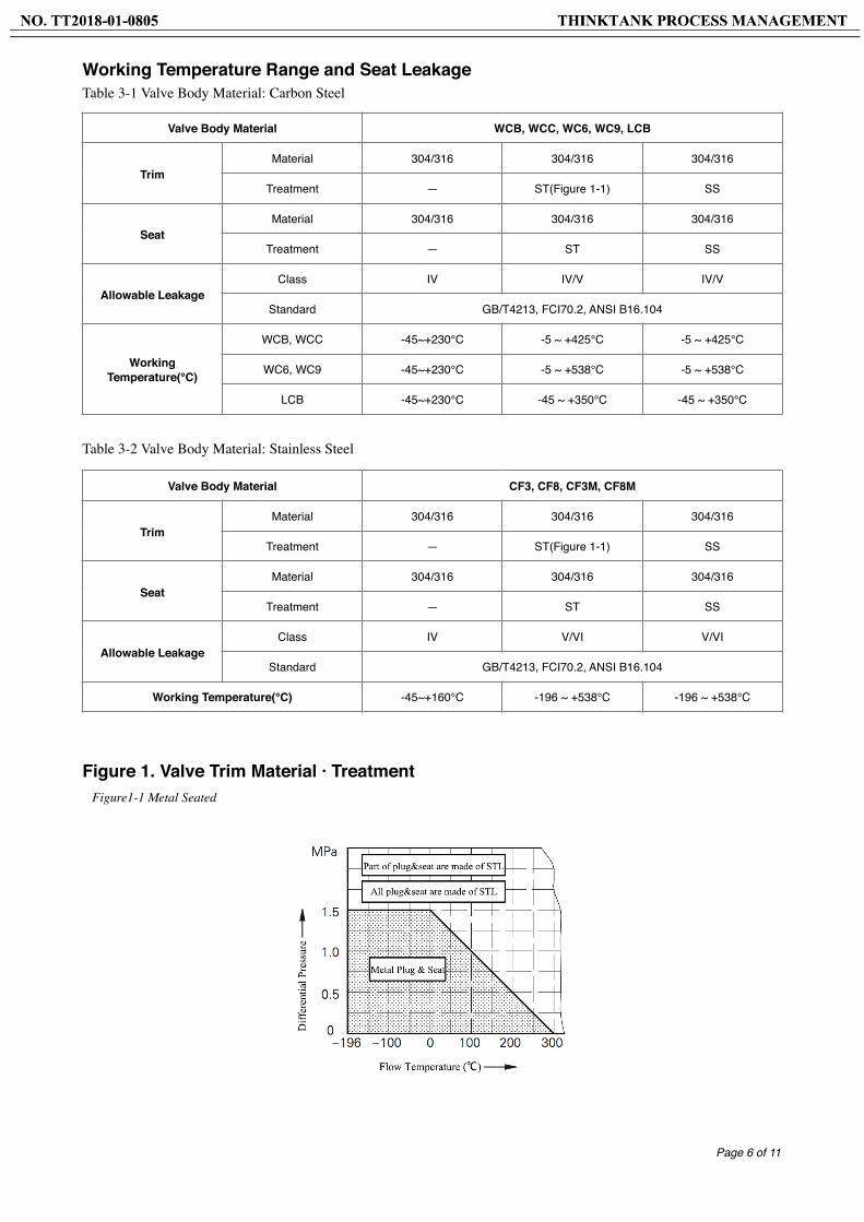
Working Temperature Range and Seat LeakageTable 3-1 Valve Body Material: Carbon Steel
Table 3-2 Valve Body Material: Stainless Steel
Figure 1. Valve Trim Material · Treatment Figure1-1 Metal Seated
Page � of �6 11
Valve Body Material CF3, CF8, CF3M, CF8M
TrimMaterial 304/316 304/316 304/316
Treatment — ST(Figure 1-1) SS
SeatMaterial 304/316 304/316 304/316
Treatment — ST SS
Allowable LeakageClass IV V/VI V/VI
Standard GB/T4213, FCI70.2, ANSI B16.104
Working Temperature(℃) -45~+160℃ -196 ~ +538℃ -196 ~ +538℃
Valve Body Material WCB, WCC, WC6, WC9, LCB
TrimMaterial 304/316 304/316 304/316
Treatment — ST(Figure 1-1) SS
SeatMaterial 304/316 304/316 304/316
Treatment — ST SS
Allowable LeakageClass IV IV/V IV/V
Standard GB/T4213, FCI70.2, ANSI B16.104
Working Temperature(℃)
WCB, WCC -45~+230℃ -5 ~ +425℃ -5 ~ +425℃
WC6, WC9 -45~+230℃ -5 ~ +538℃ -5 ~ +538℃
LCB -45~+230℃ -45 ~ +350℃ -45 ~ +350℃

Figure 2. Working Temperature of Packing Material · Pressure Ranges Figure 2-1 V-Type RPTFE Figure 2-2 PTFE+Carbon Fiber/PTFE+Asbestos Figure 2-3 Flexible Graphite
The Principle of Action
Description:
The plug structure of Three-way control valve is designed flow to open. If valve plug in the valve seat that is mixing service control valve. There are two input port and one outlet port(see Figure a, b). The valve plug is located on the outside of the valve seat that is diverting service control valve. There is one inlet port and two outlet ports (see Figure c, d). Due to three-way control valve have opening and closing operation at the same time, so three-way control valve don't have air to open or air to close such type.
• For Direct Action Mixing Service, air failure means vertical pass(B → AB). But for Reverse Action Mixing Service, air failure means flow is horizontal pass (A → AB)
• For Direct Action Diverting Service, air failure means horizontal pass (AB → A). But for Reverse Action Diverting Service, air failure means flow is vertical pass(AB → B)
Page � of �7 11
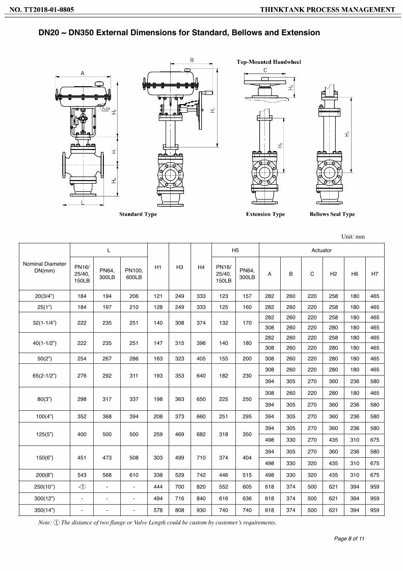
DN20 ~ DN350 External Dimensions for Standard, Bellows and Extension
Unit: mm
Note: ① The distance of two flange or Valve Length could be custom by customer’s requirements.
Page � of �8 11
Nominal Diameter DN(mm)
L
H1 H3 H4
H5 Actuator
PN16/25/40, 150LB
PN64, 300LB
PN100, 600LB
PN16/25/40, 150LB
PN64, 300LB A B C H2 H6 H7
20(3/4”) 184 194 206 121 249 333 123 157 282 260 220 258 180 465
25(1”) 184 197 210 128 249 333 125 160 282 260 220 258 180 465
32(1-1/4”) 222 235 251 140 308 374 132 170282 260 220 258 180 465
308 260 220 280 180 465
40(1-1/2”) 222 235 251 147 315 396 140 180282 260 220 258 180 465
308 260 220 280 180 465
50(2”) 254 267 286 163 323 405 155 200 308 260 220 280 180 465
65(2-1/2”) 276 292 311 193 353 640 182 230308 260 220 280 180 465
394 305 270 360 236 580
80(3”) 298 317 337 198 363 650 225 250308 260 220 280 180 465
394 305 270 360 236 580
100(4”) 352 368 394 208 373 660 251 295 394 305 270 360 236 580
125(5”) 400 500 500 259 469 682 318 350394 305 270 360 236 580
498 330 270 435 310 675
150(6”) 451 473 508 303 499 710 374 404394 305 270 360 236 580
498 330 320 435 310 675
200(8”) 543 568 610 338 529 742 446 515 498 330 320 435 310 675
250(10’’) -① - - 444 700 820 552 605 618 374 500 621 394 959
300(12”) - - - 494 716 840 616 636 618 374 500 621 394 959
350(14”) - - - 578 808 930 740 740 618 374 500 621 394 959
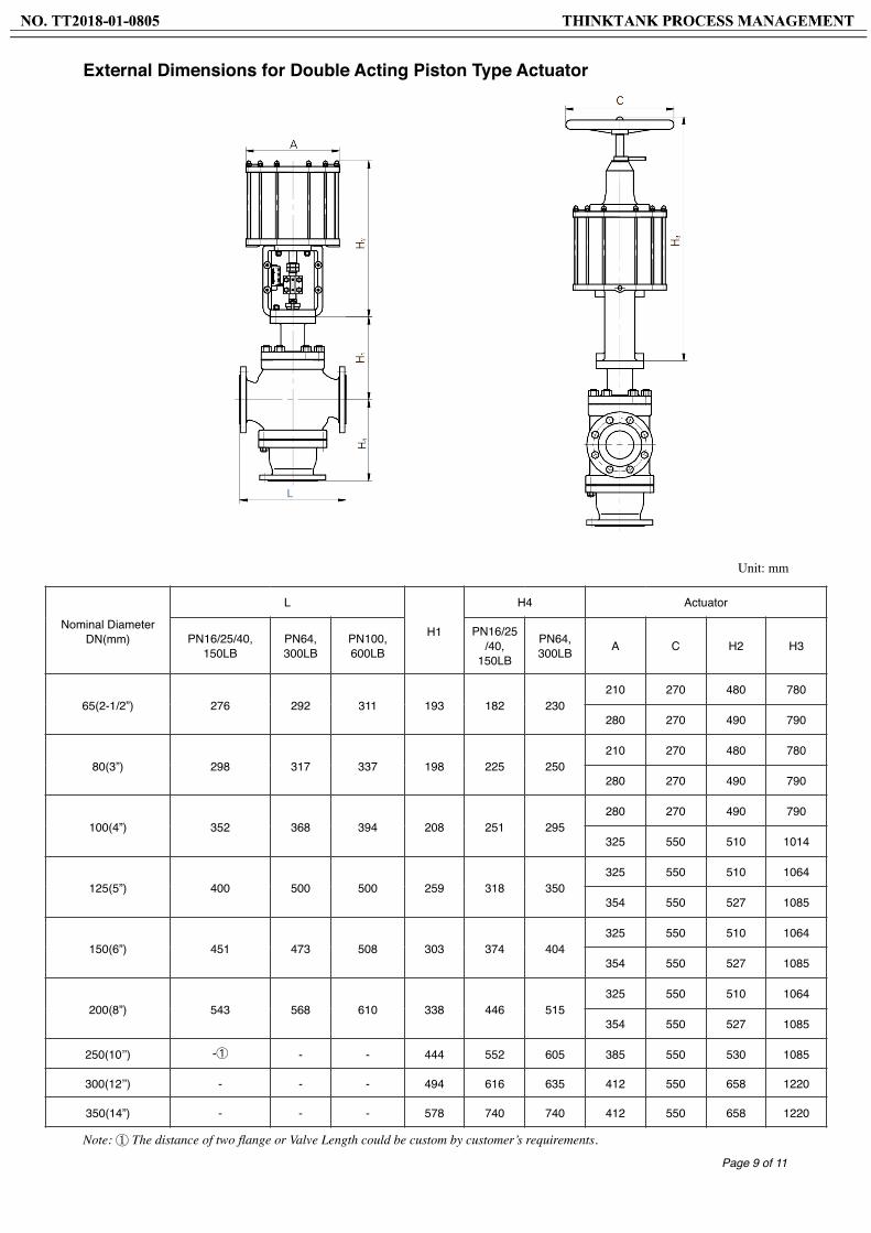
External Dimensions for Double Acting Piston Type Actuator
Unit: mm
Note: ① The distance of two flange or Valve Length could be custom by customer’s requirements.
Page � of �9 11
Nominal Diameter DN(mm)
L
H1
H4 Actuator
PN16/25/40, 150LB
PN64, 300LB
PN100, 600LB
PN16/25/40,
150LB
PN64, 300LB A C H2 H3
65(2-1/2”) 276 292 311 193 182 230210 270 480 780
280 270 490 790
80(3”) 298 317 337 198 225 250210 270 480 780
280 270 490 790
100(4”) 352 368 394 208 251 295280 270 490 790
325 550 510 1014
125(5”) 400 500 500 259 318 350325 550 510 1064
354 550 527 1085
150(6”) 451 473 508 303 374 404325 550 510 1064
354 550 527 1085
200(8”) 543 568 610 338 446 515325 550 510 1064
354 550 527 1085
250(10’’) -① - - 444 552 605 385 550 530 1085
300(12’’) - - - 494 616 635 412 550 658 1220
350(14”) - - - 578 740 740 412 550 658 1220
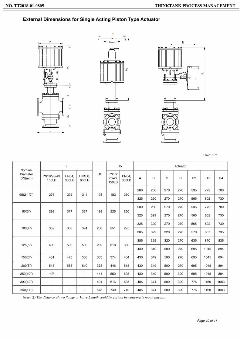
External Dimensions for Single Acting Piston Type Actuator
Unit: mm
Note: ① The distance of two flange or Valve Length could be custom by customer’s requirements.
Page � of �10 11
Nominal Diameter DN(mm)
L
H1
H5 Actuator
PN16/25/40, 150LB
PN64, 300LB
PN100, 600LB
PN16/25/40, 150LB
PN64, 300LB A B C D H2 H3 H4
65(2-1/2”) 276 292 311 193 182 230280 250 270 270 535 772 700
325 250 270 270 565 802 730
80(3”) 298 317 337 198 225 250280 250 270 270 535 772 700
325 329 270 270 565 802 730
100(4”) 352 368 394 208 251 295325 329 270 270 565 802 730
385 329 320 270 570 807 735
125(5”) 400 500 500 259 318 350385 329 320 270 635 870 835
430 349 500 270 695 1045 894
150(6”) 451 473 508 303 374 404 430 349 500 270 695 1045 894
200(8”) 543 568 610 338 446 515 430 349 500 270 695 1045 894
250(10’’) -① - - 444 552 605 430 349 500 320 695 1045 894
300(12’’) - - - 494 616 635 485 374 500 320 775 1169 1083
350(14”) - - - 578 740 740 485 374 500 320 775 1169 1083
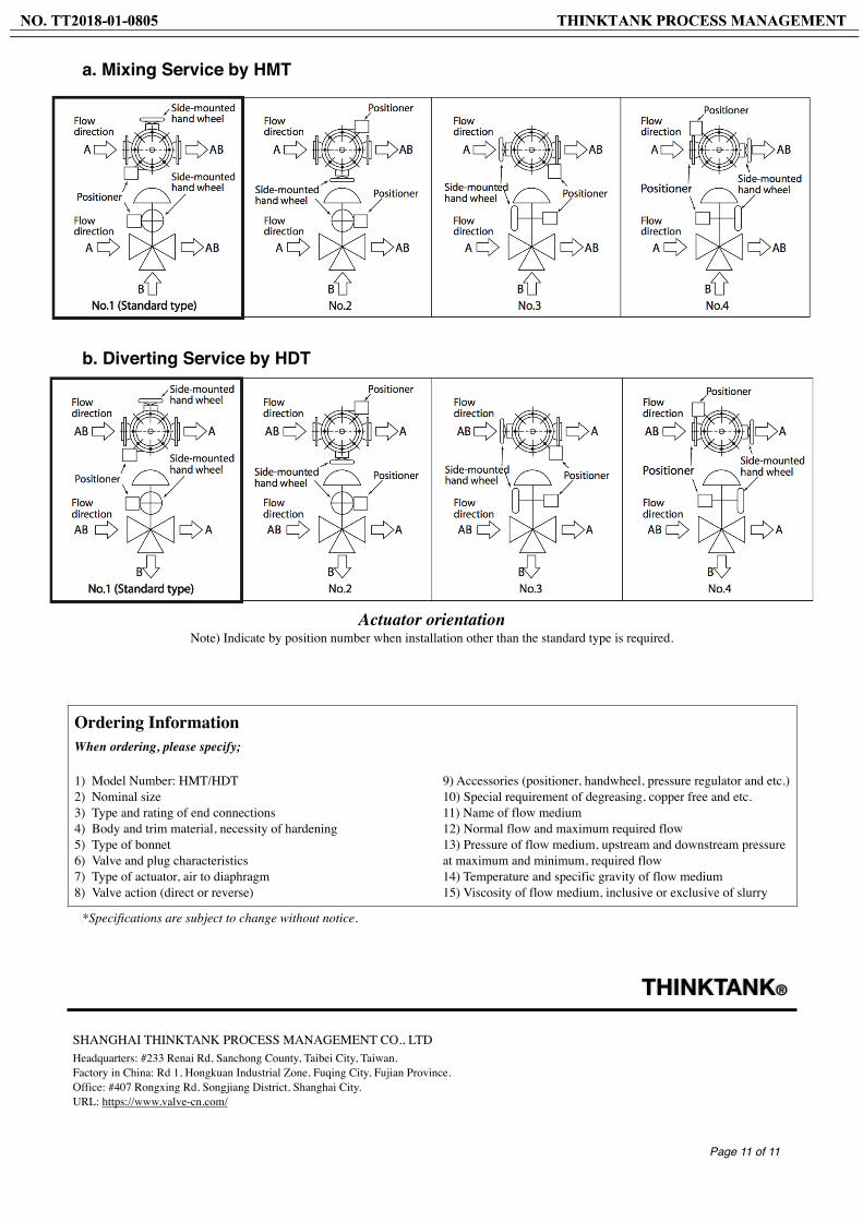
a. Mixing Service by HMT
b. Diverting Service by HDT
Actuator orientationNote) Indicate by position number when installation other than the standard type is required.
*Specifications are subject to change without notice.
Page � of �11 11
SHANGHAI THINKTANK PROCESS MANAGEMENT CO., LTDHeadquarters: #233 Renai Rd, Sanchong County, Taibei City, Taiwan.Factory in China: Rd 1, Hongkuan Industrial Zone, Fuqing City, Fujian Province. Office: #407 Rongxing Rd, Songjiang District, Shanghai City.URL: https://www.valve-cn.com/
Ordering Information When ordering, please specify;
1) Model Number: HMT/HDT 2) Nominal size 3) Type and rating of end connections 4) Body and trim material, necessity of hardening 5) Type of bonnet 6) Valve and plug characteristics 7) Type of actuator, air to diaphragm8) Valve action (direct or reverse)
9) Accessories (positioner, handwheel, pressure regulator and etc.)10) Special requirement of degreasing, copper free and etc. 11) Name of flow medium 12) Normal flow and maximum required flow 13) Pressure of flow medium, upstream and downstream pressure at maximum and minimum, required flow 14) Temperature and specific gravity of flow medium 15) Viscosity of flow medium, inclusive or exclusive of slurry
THINKTANK®