h.m.s. glamorgan - atlantic modelsatlanticmodels.net/onewebmedia/glamorgan350.pdf · ·...
TRANSCRIPT

County Class Destroyer (DLG)
H.M.S. Glamorgan1978
1/350 Scale
HMS Glamorgan was one of eight ships of the County Class Guided Missile Destroyers that were designed for the Royal Navy around the Sea Slugmissile system.Laid down in September 1962 at Vickers- Armstrong’s shipyards on the Tyne, she was launched two years later on 9th July 1964, by Lady Brecon.Commissioning day was Friday 14th of October 1966 at Tynside, where again Lady Brecon welcomed the first HMS Glamorgan in to the RoyalNavy.A lengthy period of trials followed by work ups to get all the ships systems working and the ships company settled in and familiar with their newsurroundings, after the long period in temporary accommodation whilst the building was in progress, but finally in May 1967 HMS Glamorgan wasgiven her first foreign visits to Denmark and Holland.Also in May 1967, her first helicopter flight was formed at RNAS Portland with a Westland Wessex HAS 1 anti submarine helicopter, which workedup and joined the ship in April 1968 for her first deployment to the Far East via the Caribbean, USA and west coast of Canada after transiting thePanama canal.From there she transited the Pacific Ocean calling in Hawaii and on to Singapore, The Phillipines and Australia before starting the homeward legacross the Indian Ocean to South Africa. Then back up the Atlantic Ocean to Barbados and Puerto Rico before arriving back home to completea circumnavigation of the globe in 355 days.
In the period 1977 to 1979 Glamorgan had a major refit during which time her gun turret in ‘B’ position was removed to facilitate the fitting of aquadruple bank of Exocet missile launchers. She also had her middle pair of boats removed and a triple STWS torpedo launcher fitted to the maindeck on each side in their place. A large platform was added to the front of the main mast that spanned across the entire width of the ship, to whichwas added a pair of SCOT radomes for long range communications.
In 1982, HMS Glamorgan along with her sister ship HMS Antrim became involved in the Falkland Islands campaign in the South Atlantic in whichthe Argentine forces pre emptively invaded the islands after Argentina had claimed sovereignty.Glamorgan was already at sea at the time and was soon diverted to take up station with the British task force that had sailed south. She initially wasthe flagship of Rear Admiral Sandy Woodward until the 15th April when he transferred his flag to HMS Hermes.From then, Glamorgan proved that her most useful tool was her remaining 4.5 inch twin gun mounting which she used to bombard Argentine shorepositions around Port Stanley. In early May HMS Glamorgan was slightly damaged in an air raid by Argentine air force Daggers, after two 500lbbombs fell close by.During mid May Glamorgan was again bombarding Argentine positions on the east of the islands, helping divert attention from the landings inSan Carlos water. She was also directing her fire against the airfield at Port Stanley, and at one point fired a Sea Slug missile at the airfield.In early June, Glamorgan was tasked with protecting shipping away from the islands, as the campaign built up to it’s final offensives, she was calledin again on the 11th, to provide support to the Royal Marines fighting the Battle of Two Sisters.The following morning HMS Glamorgan was attacked by an Exocet missile launched from an Argentine position using an improvised shore basedlauncher. The incoming missile was tracked visually and by Glamorgan’s Ops room . The ship executed an evasive turn away from the missile butnot enough time was available and the missile struck Glamorgan on the port side aft, bouncing across the deck before exploding against the hangar,destroying the ship’s helicopter and starting a major fire.Sadly, 14 of the ships company were killed and many more wounded, but Glamorgan survived the attack. The fire was extinguished and the damagerepaired temporarily. Two days later the Argentine forces surrendered and she was able to make more substantial repairs that would allow her tosail for home. HMS Glamorgan arrived back in Portsmouth on 10th July 1982 after being at sea for 104 days.
HMS Glamorgan spent the rest of 1982 in refit, but was back at sea again in early 1983. Her last active deployment for the Royal Navy was off thecoast of Lebanon assisting peacekeeping forces there in 1984.She was decommissioned in 1986 and sold to the Chilean Navy who re-named her the Almirante Latorre. She served with the Chilean Navy until1998 when she was decommissioned again and laid up. On April 11th 2005 she sank in the South Pacific whilst being towed to the breakers .
General PrecautionsWhen assembling a Resin / Photoetched metal kit, certain precautions must first be taken.1. Resin dust can be harmful if inhaled. It is recommended that you wear a suitable dust mask when drilling or sanding resin parts.2. Cyano adhesives (super glues ) are generally used to assemble this type of kit. Care must be taken when using this type of adhesive as it will bond inseconds. Follow the advice on the container.3.Wash resin parts in a solution of warm soapy water before assembly. This will remove any residual mold release agents and ensure a good key forpainting.4. Soak photoetch parts in a suitable solvent, such as white spirit, to degrease the surfaces prior to painting.
SpecificationsLength: 520 feet (160 m) Beam: 53 feet (16 m) Displacement: 6,200 tonnes full load Propulsion: COSAG (Combined Steam and Gas Turbine)
Speed: 30 knots maximum Range: 4000 nautical miles at 28 knots Crew: 471
History
Armament
2 x Twin 4.5inch Mk 6 Gun Turrets mounted forward. Later B Turret was replaced by 4 x MM40 Exocet Missile Box Launchers2 x 20mm Single Oerlikon Mountings 1 x Sea Slug GWS 2 SAM Twin Launcher (24 Missiles) 2 x Quad Sea Cat GWS 22 SAM
2 x STWS Triple Tube Torpedo Launchers 1 x Wessex HAS Mk 3 Anti Submarine Helicopter

Ph
oto-
Etc
hed
Met
al P
arts
1
2
3 4
5
6 7
8
9
10
11
1213
14 15
16
17
1819
20
21
22
23
24 25
2627
2829 30
31
3233
34
35
36
37
3839
40
41
42
43
4445
46
48 49
50 51
52 53
5455
56
57
58
59
60
6162
6364
65
66
6768
69
7071
7274
75
7677
78
7980
8182
7383
8485
86
8788
8990
91 92
93
94
9596
97
98
9910
010
1
102
103 10
410
510
6
107
108
109
110
111
112
113
114
115
116
117
118
119
120
1.R
ailin
gs (3
Bar
Off
set S
tock
)2.
Rai
lings
(Qua
rterd
eck)
3.R
ailin
gs (F
ocsl
e)4.
Rai
lings
(Fw
d Su
pers
truct
ure
Dec
k St
bd)
5.R
ailin
gs (F
wd
Supe
rstru
ctur
e D
eck
Port)
6.R
ailin
gs (F
wd
Dire
ctor
Pla
tform
)7.
Rai
lings
(901
Rad
ar P
latfo
rms)
8.R
ailin
gs (
Mai
n M
ast P
latfo
rm)
9.R
ailin
gs (
Fore
Mas
t Pla
tform
)10
.R
ailin
gs (M
ain
Mas
t Pla
tform
s)11
.R
ailin
gs (
992
Plat
form
)
12.
Rai
lings
(901
Dec
k)13
.R
ailin
gs (P
ort B
oat L
adde
rway
)14
.R
ailin
gs (H
anga
r Roo
f)15
.R
ailin
gs (S
CO
T P
latfo
rm)
16.
Rai
lings
(Aft
Funn
el D
eck)
17.
Rai
lings
( Fo
re D
eck
Step
)18
.R
ailin
gs (M
ain
Mas
t Dec
k)19
.H
anga
r Ven
t Gril
ls20
.Fl
ight
Dec
k L
ight
Clu
ster
21.
Mai
n M
ast G
aff
22.
Flig
ht D
eck
Safe
ty N
ets
23.
Boa
t Dav
it T
ops
24.
Sea
Cat
Mis
sle
Win
gs25
.Se
a C
at M
issi
le B
odie
s26
.A
ncho
r Cha
in27
.Se
a Sl
ug T
elem
etry
Ant
enna
28.
Yar
darm
(For
e M
ast F
ront
)29
.Y
arda
rms (
Fore
Mas
t Sid
es)
30.
Swee
p B
uoy
Cra
ne31
.Y
arda
rms (
Mai
n M
ast S
ides
)32
.Y
arda
rms (
Mai
n M
ast R
ear)
33.
Swor
d an
d Sh
ield
Ant
enna
34.
Fore
Mas
t Gaf
f35
.Y
arda
rms (
Low
er E
CM
Sen
sors
)36
.Sh
ips N
ame
Plat
es37
.Y
arda
rms (
Fore
Fun
nel S
ides
)38
.E
CM
Sen
sor T
op S
tays
39.
GD
P B
ulw
ark
Lig
hts
40.
Ven
t Gril
ls (M
ain
Mas
t Dec
k St
ep)
41.
Flig
ht D
eck
Aft
Safe
ty N
ets
42.
Ven
t Gril
ls (
Aft
Funn
el S
ides
)43
.V
ent G
rill (
Aft
Funn
el R
ear)
44.
Ven
t Gril
ls (
Fwd
Funn
el S
ides
)
45.
Ven
t Gril
ls46
.V
ent G
rills
(Aft
Supe
rst S
ides
)47
.E
CM
Sen
sor T
rays
48 to
64
Sea
Slu
g L
aunc
her A
ssem
bly
65.
Jack
Sta
ff66
.H
untre
ss B
ow R
ail
67.
277
Rad
ar A
nten
na68
.D
F A
nten
na (R
ecta
ngul
ar)
69.
DF
Ant
enna
(Circ
ular
)70
.D
F A
nten
na M
ast
71.
Hel
icop
ter R
otor
s (Fo
lded
)
72.
Hel
icop
ter R
otor
s (Sp
read
)73
.L
ife R
aft R
ack
(Dou
ble)
74.
Hel
icop
ter T
ail W
heel
75.
Hel
icop
ter T
ail R
otor
76.
Hel
icop
ter T
ail S
tabi
liser
77.
Hel
icop
ter R
otor
Hub
Dou
bler
s78
.H
anga
r Doo
rs79
.Fu
nnel
Bad
ges (
Ham
pshi
re)
80.
Boa
t Dav
it B
ase
(For
war
d)81
.B
oat D
avit
Bas
e (A
ft)82
.B
oat D
avit
Bas
e (M
id B
oats
)
47a
47b

Photo-Etched Metal Parts (Continued)
83. Corvus Sights84. Funnel Badges (Antrim)85. RAS Mast86. Funnel Badges (Glamorgan)87. Funnel Badges (Norfolk)88. Funnel Badges (London)89. Funnel Badges (Kent)90. Funnel Badges (Fife)
99. Accommodation Ladders (Stowed)100. Fore Mast Sensors101. Torpedo Loading Arms102. Fore Mast Gaff (Upper)103. 20mm Oerlikon Mountings104. GDP Rangefinder Sights105. Inclined Ladder (Spare)106. Inclined Ladder (Port Boats)
91. Life Belts92. Life Belt Ejector Rack93. Funnel Badges (Devonshire)94. Sea Cat Loading Cranes95. Exocet Launcher Shields (Inner)96. Exocet Launcher Shields (Outer)97. Boat Fuel Can Racks98. Dan Bouys
107. Sea Slug Loading Frame108. Life Raft Racks (Double)109. Inclined Ladders (Aft Hull Step)110. Inclined Ladder (Fwd Director)111. Vertical Ladder Stock112. to119. 965 Radar Antenna Assembly120. Sea Cat Launcher Rails
15
22 23
16
25 2927 28 3121
35
17
24
38
2630
1 23
4
5
6
78 9
1011 12
13 14
1. Aft Funnel2. Fore Funnel3. Gun Direction Platform (GDP)4. Fore Mast5. Main Mast
6. SCOT Platform7. 901 Radar Dish Yolk8. 901 Radar Dish9. Exocet Blast Shield10. Exocet Missile Box Mounting
11. Sonar Dome12. 4.5” Mk 6 Gun Turret13. Sea Cat Director Platform (Port)14. Sea Cat Director Platform (Stbd)15. Wessex HAS Mk3 Helicopter.
Resin Parts
White Metal Parts
21. Sea Slug Missile Launcher Yoke22. 992 Radar Antenna23. 1006 Radar Antenna24. Deck Winch
25. GWS22/904 Fire Control Director x 326. 903 Director Tubs x 227. Sea Cat Missile Launcher x 228. Corvus Chaff Rocket Launcher x 229. SCOT Comms House
30. Anchors x 231. STWS Torpedo tubes x 232. Life Raft Cannisters x 1833. 4.5” Gun Barrels x 234. Propellers x 1 pair
35. Propeller A Frame x 236. Rudder x 237. Stabiliser Fins x 838. Main Mast ECM Array x 2
Large Resin Parts
Forward Superstructure and Bridge Aft Superstructure and Hangar
33 36
32
37
18 19 20
16. Exocet Missile Box Launcher x 417. SCOT Radomes x 218. Fairey Huntress Power Boat19. Cheverton Motor Boat x 220. 27” Whaler
34

Main Parts Location
4.5” Gun TurretAssembly
ForwardSuperstructure
AftSuperstructure
10
9
25
4
22
2
1
56
13
25
3
It is recommended that if the ship is to be modelled in full hull form, thatthe lower hull be joined to the upper hull first of all. Any seam along thejoin line may then be filled and blended in, before any construction ofthe smaller parts takes place.
Fitting of the larger parts such as the Fore and Aft Superstructure, may take placeat an early stage so that the smaller parts and details may be added aroundthem.
When the model has been constructed to the stage of fittingthe masts into place, assemble the masts according to thediagrams in further sections.Fit the assembled fore mast down to the deck over a locatingpeg at the rear of the GDP.
The main mast locates centrally on the aft superstructuredeck over two locating pegs. Fit the Funnels and GDP intoplace before spray painting. This is so that any seams in thejoints may be filled and smoothed prior to painting.....

Sea Slug Missile Launcher Assembly
50
61
61
48
49
51
52
53
60
59
57
55
58
54
62
63
5664
57
The Sea Slug missile launcher is a very complex piece ofequipment, so the assembly of the photo etched parts hasbeen designed to be as easy as possible and give the bestamount of strength to the finished article.It is best to spray the etched parts with an auto motiveprimer paint before assembly.
First assemble etched parts 50 and 51, the outer vertical frames,to the central horizontal plates, etched parts 48 and 49. Shapethe vertical frames to match the etched lines on the horizontalplates and fit them in place. Fit the small forward angular frameetched part 61 to the front vertical bar of each of the verticalframes.
Next fit the inner vertical frames, etched parts 52 and 53 in thesame way by shaping to fit into the etched lines on parts on theupper and lower horizontal plates.Note..DO NOT remove the thin joiner lines from the horizontalplates, etched parts 48 and 49 at this stage.
Fit the upper and lower horizontal frames, etched parts 59 and60 to the top edges of the vertical frames, which should matchup to the long bars running fore and aft. Fold down the smallside braces so that they fit against the outer edges of the centrehorizontal plates.Join the upper and lower halves of the launcher together so thatthe shapes of the flat surfaces of the central plates mate exactly.
The thin joiner bars on the central plates may now be cut away.
Fit the top angled braces, etched parts 57, into place on the spanwisebars as shown below. Retain the very rear most frame for fitting ata later stage.
Fit the fore and aft frames, etched parts 54 and 55 as shown below sothat they fit on to a fore and aft bar and 55 fits between the verticalson parts 57.
Fit etched part 62, to the very front spanwise bar on the underside ofthe launcher, followed by etched parts 56, which fit to a fore and aftrunning bar on the underside and also fit against the verticals of 62.Fit frames, etched parts 63, so that the verticals of the front frame fitto the rear of etched parts 56. All these frames fit on to spanwise barson the underside of the launcher.
Fit etched part 64 to the rear most spanwise bar, after first cutting offthe small relief etched square, which is then fitted to the rear of theextension piece as shown below.
Fit the flat horizontal plate of the mechanism etched parts 58, so thatthe forward ends of the longerons fit against the rear of the centrespanwise frame 57. The outer prongs if you like, fit out away fromthe launcher and attach to the top of the mounting yolk forks.Fit the long vertical plates to the longerons as shown below.Fit the retained frame from etched parts 57 so that the verticals fitagainst the rear of the vertical plates. Fit the small fillets to the rearof the frame.

Twin 4.5” Mk6 Gun Turret Assembly
Clean off any excess material from the gun barrels, parts 33, so that thebarrels and the elevation discs are clean and smooth.Fit the elevation discs on both barrels into the recesses in the front ofgun turret, resin part 12. Elevate the barrels to the desired position andsecure into place.
Missile Launcher Yoke Location Sea Slug Missile Launcher Assembly Location
20mm Oerlikon Mounting Sea Cat Missile Launcher
965 AKE-2 Double Bedstead Radar Antenna
103
25
24
120
115119
119
118
118
117
116
113
112
114
112
21
21
24
12
33
Trim down the spidles inside the top of the yoke forks until the launcherassembly slides in between with a tight fit.Secure into place at the desired angle of elevation.
Fit the Sea Slug missile launcher assembly intoplace on the mounting spindle on the quarter-deck.The assembly may be trained in whatever directiondesired and fixed in place.
Fold the shoulder rests on the rear of the gun around to 90ºso that they are parallel, then fold them up to 90º to fitagainst the back of the gun. Twist the gun sight to 90º.Fit the 20mm gun mounting to the tops of the pintles thatare situated on each side of the forward superstructure topdeck just behind the fore mast.Fit the gun shield centrally to the locating lug just belowthe mid point on the gun.
Assemble the Sea Cat missiles using etched parts 24 and 25 as shownabove. These can be fitted to the launcher as desired.Fit the side rails, etched parts 120, to the short sides of the launcher.
To assemble the 965 Antenna, first fit the Mesh Screens, etched parts 118 tothe vertical bars on the Front Face Plate, etched part 115 as shown above left.Make sure that the Mesh Screens parts 119 fit to the central position of thelower row as they have the mounting base attachments fitted to them.Fit the Rear Face Plate, etched part 117, to the rear of the mesh screens usingthe vertical bars as location points.Note that the mesh screens narrow together when viewed from above. See thediagram on the next page.
Fit Tie Bars, etched parts 113 across the top and bottom of the antenna as shownright. Fit the Counter Frames etched parts 114, to the underside of the antenna.Fit the small mounting plate 22, if desired, to the lugs on the centre mesh screens.Alternatively the lugs on the centre screens can be located over the spindle on topof the main mast and secure in to place.

Top View
Bottom View
965 Plan Views
The above views show the alignment of the mesh screens in relation to thefront and rear face plates. They also show the positions of the counter framesand the tie bars
117 113
117
113
112 115
115118
119118 67 7
7
8
65
3
3011
17
16
4
5
6
13
25
29
28
32
68
70
10439
37
277 Radar Antenna Assembly 901 Radar Antenna
Fo’c’sle Fittings Exocet Deck Fittings
Forward Superstructure Fittings
70
Fold the forks of the 277 radar mounting in half, sothat the relief etched detail is outermost.Gently curve the antenna dish as shown above, thentrap the lugs on the sides of the antenna dish betweenthe tops of the forks and then secure into place.
Gently curve the sections of railings, etched parts 3, to fitalong the edges of the focsle deck. The forward part of therailings pass inboard of the anchor recess before meetingat the Jack Staff.
To fit the anchors it will be necessary to drill out the hawse-pipeholes further by using a 1.5mm drill bit.
Shape and fit the railing sections, etched part 17, to the edges of the forward hull step.Ensure there is a gap on each side of the centre section to allow for a ladder access.
Fit the four Exocet missile box launchers into the mounting base. The two outboardboxes fit in between the splitter plates. If by any chance these splitter plates have beendamaged by whatever cause, there are replacement parts in the etched detail set, etchedparts 95 and 96.
Fold the four side frames on etched part 70 downuntil the edges touch, then secure in to place.Two different shapes of DF antenna have beensupplied in the etched parts, items 68 and 69.Both are assembled as shown left, and fitted tothe top of the short mast, part 70, as desired forthe ship being modelled.
Shape and fit the railing sections to the edges of the top deck on the Forward Superstructure,etched parts 4 and 5. Note that the short sections of railing at the rear part of the deck aredifferent lengths to fit around differing shaped deck edges.Shape and fit the railing sections, etched parts 6 and 13 to the platforms as shown above.
Fit the forward 904 Fire Control Director, metal part 25, to the platform behind the bridge asshown right.Fit the DF antenna mast, etched part 70, centrally to the top deck, half way between the 904platform and the GDP housing.Fold the rangefinder sights, etched parts 104, in half so that the relief detail is outermost. Fitto the small raised platforms inside the GDP enclosure. Fit the small light fittings, etchedparts 39, to the outside of the GDP bulwarks as shown right.Fit the funnel yardarms, etched parts 37, to the sides of the forward funnel. Fit the SCOTcommunications house, metal part 29, to the raised rectangle on the deck, aft of the forwardfunnel.Fit life raft canisters, metal parts 32, to the raised bases moulded on to the deck around therear edges of the superstructure as shown right.
22
23
4
11
9
9
29
29
28
100
102
34
108
108
101
101
40
32
18
18
16
16
32
31
31
5
38
47b
47a
38
38
Main Mast Yardarms and ECM Antenna Assembly
Aft Superstructure Fittings
Fore Mast Assembly
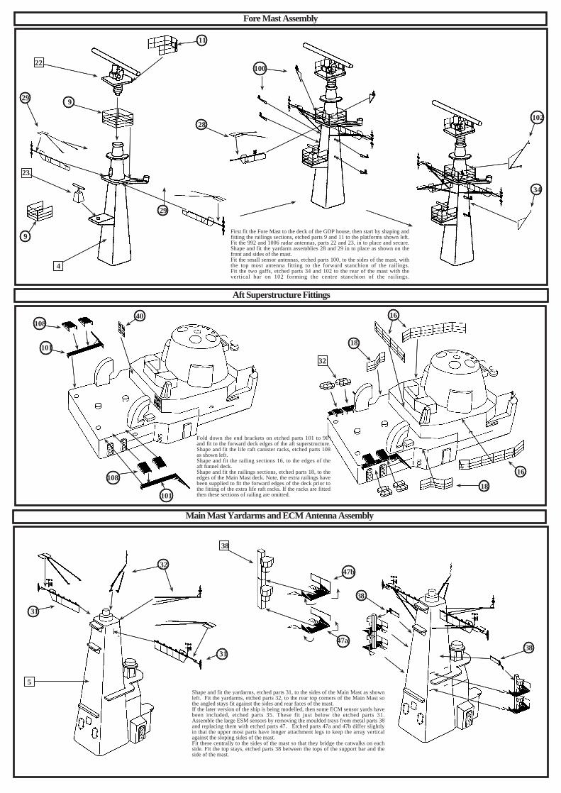
First fit the Fore Mast to the deck of the GDP house, then start by shaping andfitting the railings sections, etched parts 9 and 11 to the platforms shown left.Fit the 992 and 1006 radar antennas, parts 22 and 23, in to place and secure.Shape and fit the yardarm assemblies 28 and 29 in to place as shown on thefront and sides of the mast.Fit the small sensor antennas, etched parts 100, to the sides of the mast, withthe top most antenna fitting to the forward stanchion of the railings.Fit the two gaffs, etched parts 34 and 102 to the rear of the mast with thevertical bar on 102 forming the centre stanchion of the railings.
Fold down the end brackets on etched parts 101 to 90ºand fit to the forward deck edges of the aft superstructure.Shape and fit the life raft canister racks, etched parts 108as shown left.Shape and fit the railing sections 16, to the edges of theaft funnel deck.Shape and fit the railings sections, etched parts 18, to theedges of the Main Mast deck. Note, the extra railings havebeen supplied to fit the forward edges of the deck prior tothe fitting of the extra life raft racks. If the racks are fittedthen these sections of railing are omitted.
Shape and fit the yardarms, etched parts 31, to the sides of the Main Mast as shownleft. Fit the yardarms, etched parts 32, to the rear top corners of the Main Mast sothe angled stays fit against the sides and rear faces of the mast.If the later version of the ship is being modelled, then some ECM sensor yards havebeen included, etched parts 35. These fit just below the etched parts 31.Assemble the large ESM sensors by removing the moulded trays from metal parts 38and replacing them with etched parts 47. Etched parts 47a and 47b differ slightlyin that the upper most parts have longer attachment legs to keep the array verticalagainst the sloping sides of the mast.Fit these centrally to the sides of the mast so that they bridge the catwalks on eachside. Fit the top stays, etched parts 38 between the tops of the support bar and theside of the mast.
67
8
10
5
21
33
17
6
18
66
80
81
23
80 81
15
&
Main Mast Radar Antenna Location
SCOT Platform Assembly Boat Davit Assembly
Aft Boat and Davit Positions
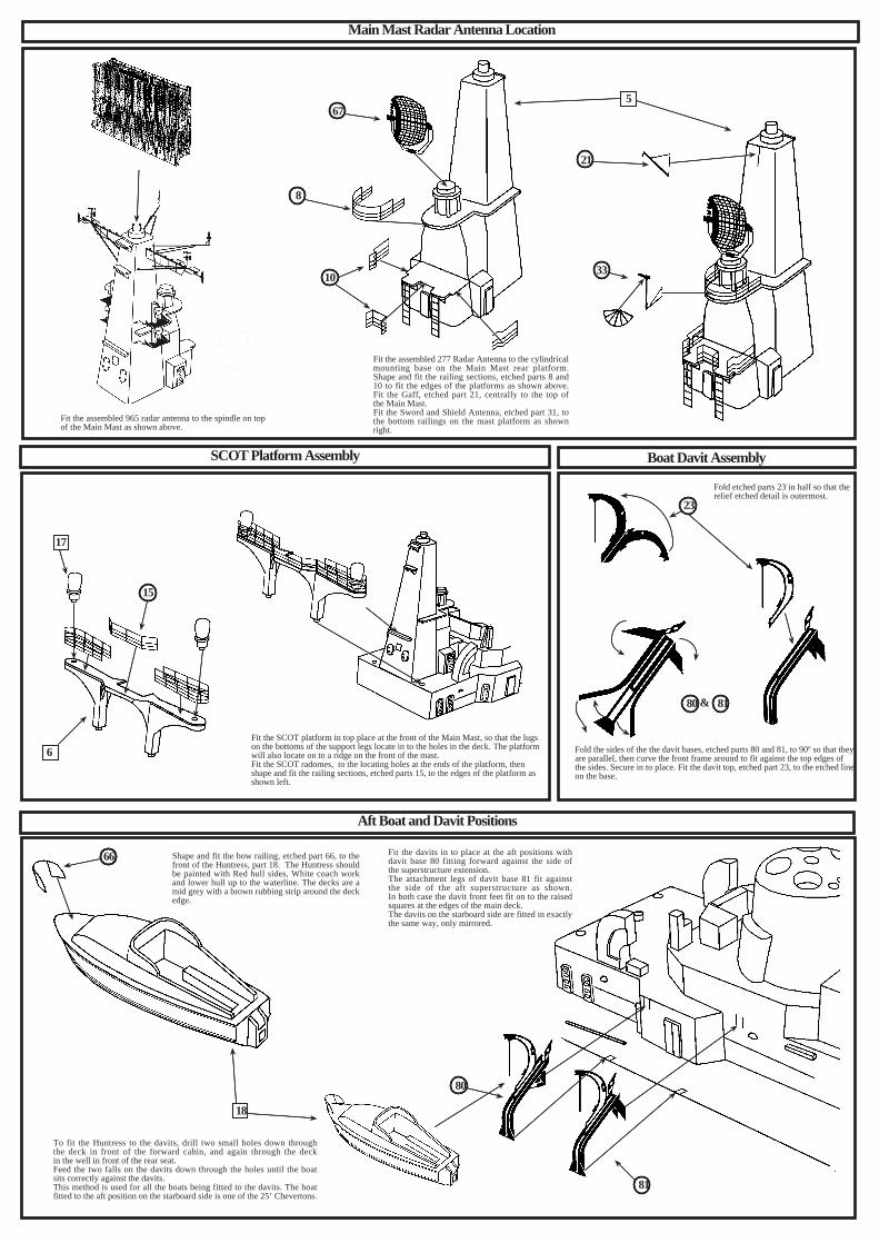
Fit the assembled 965 radar antenna to the spindle on topof the Main Mast as shown above.
Fit the assembled 277 Radar Antenna to the cylindricalmounting base on the Main Mast rear platform.Shape and fit the railing sections, etched parts 8 and10 to fit the edges of the platforms as shown above.Fit the Gaff, etched part 21, centrally to the top ofthe Main Mast.Fit the Sword and Shield Antenna, etched part 31, tothe bottom railings on the mast platform as shownright.
Fit the SCOT platform in top place at the front of the Main Mast, so that the lugson the bottoms of the support legs locate in to the holes in the deck. The platformwill also locate on to a ridge on the front of the mast.Fit the SCOT radomes, to the locating holes at the ends of the platform, thenshape and fit the railing sections, etched parts 15, to the edges of the platform asshown left.
Fold etched parts 23 in half so that therelief etched detail is outermost.
Fold the sides of the the davit bases, etched parts 80 and 81, to 90º so that theyare parallel, then curve the front frame around to fit against the top edges ofthe sides. Secure in to place. Fit the davit top, etched part 23, to the etched lineon the base.
Shape and fit the bow railing, etched part 66, to thefront of the Huntress, part 18. The Huntress shouldbe painted with Red hull sides, White coach workand lower hull up to the waterline. The decks are amid grey with a brown rubbing strip around the deckedge.
Fit the davits in to place at the aft positions withdavit base 80 fitting forward against the side ofthe superstructure extension.The attachment legs of davit base 81 fit againstthe side of the aft superstructure as shown.In both case the davit front feet fit on to the raisedsquares at the edges of the main deck.The davits on the starboard side are fitted in exactlythe same way, only mirrored.
To fit the Huntress to the davits, drill two small holes down throughthe deck in front of the forward cabin, and again through the deckin the well in front of the rear seat.Feed the two falls on the davits down through the holes until the boatsits correctly against the davits.This method is used for all the boats being fitted to the davits. The boatfitted to the aft position on the starboard side is one of the 25’ Chevertons.

13 14&
1
86
97
94
27
25
78
27
20
12
12
19
46
42
4314
83
28
19
81
80
Sea Cat Director and Launcher Location
Aircraft Hangar Fittings
Forward Boat and Davit Positions Corvus Chaff Launcher
Assemble the davits to the forward positions on the forward superstructurein the same manner as used on the aft davits, except that the attachment legson part 81 will need to be trimmed so that the forward leg is shorter to allowfor the angled superstructure side.When the davits have been fitted in all positions, a drive shaft may be addedto fit between the two davits, made from plastic rod or stretched sprue ifdesired. The boat on the forward port position is a 25’ Cheverton and on thestarboard forward position is a 27’ Whaler. These positions changed fromship to ship and indeed at various time frames too.An extra set of davits, etched parts 82 has been included to fit to the midposition on some ships, that had their boats located differently.
Fold the Corvus sight, etched part 83 in half so that the reliefetched detail is outermost and fix in to place on top of thelauncher barrels as shown above.
Fit the Corvus Chaff Launchers, parts 28,to the locating hole in the deck inside theenclosures on each side of the forwardfunnel
To fit the ventilator grills, etched parts 19 and 43, they must firstbe gently curved by rolling around a cylindrical object such as aknife handle or drill bit. Fit etched parts 19 around the curvedpillars on both port and starboard sides of the aircraft hangar,along with the vent grills, etched parts 46.Shape and fit the railing sections, etched parts 12 and 14 to fitaround the deck edges as shown. The shorter length of 12 fitson the starboard side.
Shape the starboard end of the Floodlight Frame,etched part 20, to form a step that will meet up tothe shorter length of railing on the starboard side,when fixed in place.
Fold the Telemetry Antenna pole, etched part 27, in half and fixwith the etched detail outermost. Fit the small disc by slotting iton to the base of the dipole, at the top of the antenna.
The Hangar Doors, etched part 78, may be fitted in either the open or closed position.To open the doors, concertina them by folding the sections between the etched linesalternately. Fix to the forward pillar as shown above.
Fit the Sea Cat Director Platforms, parts 14 to port and 15 to starboard, to the ridge on the sideof the aft superstructure. The foot of the vertical support should fit right against the edge of thedeck. Shape and fit some stock railing around the edge of the platform.Fit he ships funnel badges, etched part 86, to each side of the funnel. These are mirrored images.
Fold the Fuel Can Racks, etched parts 97, to shape and fit in place justforward of the director platform supports on both sides of the ship.Fit the Sea Cat Loading Cranes, etched parts 94, to the molded bracketon the aft side of the director platform supports.Fit the Sea Cat Missile Launchers to the locating holes in the deck asshown on both sides of the ship.
37
36
3534
109
107
2
22
41
30
Quarterdeck Railings and Ladders
Flight Deck Safety Net Location
Lower Hull Running Gear Location
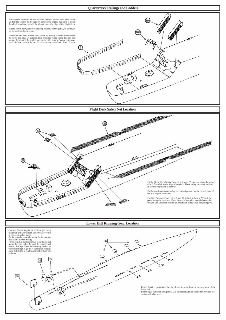
Fold up the handrails on the inclined ladders, etched parts 109, to 90ºand fit the ladders to the support bars on the angled hull step. The tophandrail stanchions should then locate over the edge of the flight deck,
Shape and fit the Quarterdeck railing section, etched part 2, to the edgesof the deck as shown right.
Shape the Sea Slug Missile door frame by folding the side frames downto 90º so that they are parallel, then bring the centre frame down so thatouter edges match the angled stay on the side frames. Secure in to placeand fit the assembly to fit above the moulded door frame.
Fit the Flight Deck Safety Nets, etched parts 22, to a line along the shipsside, 2.5mm below the edge of the deck. These safety nets may be fittedin the raised position if desired.
Fit the small sections of safety net, etched parts 41 to the curved sides ofthe hull step as shown left.
Fold the Paravane Crane, etched part 30, in half to form a ‘V’ with thepoint being the outer end. Fit to the top of the pillar moulded on to thedeck so that the inner end fits on either side of the small mounting post.
Fit the Rudders, parts 36 so that they locate in to the holes at the very stern of thelower hull.Fit the eight stabiliser fins, parts 37, to the locating holes situated in between thesections of bilge keel.
Cut two 56mm lengths of 0.75mm (30 thou)diameter brass rod from the stock providedto use as propeller shafts.Fit the propeller, centrally to the flat face on thefront of the A frame bearing.Fit the propeller shaft assemblies to the lower hullso that the open end of the shaft fits in to the hullsleeve. The legs of the A-frame may need to betrimmed in length to get the A-frame to sit correctlyon the hull, but there is sufficient length on both legsto do this.

Humbrol 69Yellow
Westland Wessex HAS 3
Ships Flights Markings
HMS Devonshire 403 / DV HMS Hampshire 402 / HA HMS Kent 401 / KEHMS London 405 / LD HMS Antrim 406 / AN HMS Glamorgan 400 / GL
HMS Fife 404 / FF HMS Norfolk 407 / NF
Humbrol 96RAF Blue Grey
Other Colours Used
Matt Black...... Wheel Tyres, Undersides of Rotor Blades.Olive Green... Top Surfaces of Rotor BladesRed and White .... Tail Rotor Blade TipsMedium Grey.... Tail Rotor Blades
77
72
76
75
74
To assemble the Wessex helicopter, first clean off any castingflash that may be around the extremities, especially the pouringlug that has been situated where the tail wheel should go.Remove this and smooth in the surface.A choice of spread or folded rotors has been given so that themodeller may choose to have the helicopter stowed in the hangarif desired.
Fit the tail rotor, etched part 75, in to place on the tail pylon asshown. To fold the tail a cut will have to be made down thefuselage just aft of the tail wheel and the tail folded along theport side of the fuselage.
Fit the tail wheel etched part 74, in to place. Etched part 76 hasbeen supplied as a replacement in case of any casting damage tothe horizontal stabiliser, and is not essential to fit otherwise.
Fit the main rotor blades, etched part 77, to the spindle on thetop of the fuselage, so the rotation would be in an anti clockwisedirection when viewed from above.If the folded blades, etched parts 71, are fitted, bend the blades atthe root so that they lay flat along side the fuselage. The blades onthe port side lay outboard of the folded tail pylon.
Decals have been supplied on the decal sheet so that the Wessexcan receive markings for any one of the helicopters carried by theeight ships of the class. The locations of these markings are shownbelow.
Other Instructions
1. Stock lengths of railings, etched parts 1, have been supplied to fit between the ends of the forward hull step railings, and the aft director platforms. There are severalgaps in the railing along the ships side where there are life raft canister racks, and the accomodation ladders, so these railings will need to be cut into shorter sections.
2. Life Raft Canister Racks, etched parts 108, have been provided to cover the areas requiring double canister mounting. Some of these have already been covered in thediagrams, but there are some racks fitted to the main deck as well. The locations of these are that there are two racks between each of the boat davits on the starboardside, and another two racks between the aft boat davits on the port side.
3. Accommodation Ladders (Stowed) Etched parts 99, fit to the deck edges on both side of the ship, just forward of the forward boat davits, with the landings positionedat the front.
4. The STWS Triple Torpedo tube mountings, parts 26, are fitted into the locating holes in the main deck, between the fore and aft boat davits.
5. Inclined Ladders have been supplied in different lengths to fit various locations on the ship. The longest ladders have already been covered in a diagram, but the smallones fit as follows. Etched part 105, is a spare and is usually stowed inboard of the port ladder on the angled aft hull step. Etched Part 106, fits from the main deckto the small landing on the port side inboard of the forward boat davits. Etched part 110, fits to the rear of the forward 904 director platform.
6. Stock lengths of vertical ladder, etched parts 111, have been supplied to fit to areas that require them. The rear of the GDP is one such place, on the starboard side ofthe mast base.
7. Anchor chain, etched parts 26, has been supplied to run from the capstans on the focsle to the hawse-pipes. There is also sufficient to run some chain from the hawsepipes to the surface of the water, if the kit is being modelled as a waterline diorama with the ship at anchor.
8. Etched parts 91 and 92, are life belts in their ejector racks. These are located on the rear of the bridge wings.
9. Dan Bouys, etched parts 98, are supplied for fitting to the edges of the deck, outboard of the aft hull step inclined ladders.
10. Etched parts 36, are the name plates for all of the ships in this class. These are located on each side of the forward superstructure just aft of the forward door on thestarboard side, and in a comparable position on the port side.
11. Funnel badges for all of the ships of the class have been provided. These are listed in the parts list as to which ships they belong. The fitment of these badges variedfrom ship to ship, some placed on the fore funnel, some on the aft funnel. Further research will be necessary to estiblish the correct location of these items.
12. Etched part 85, is a Replenishment Jackstay and is fitted to the front deck edge of the forward hull step. The tripod legs are angled aft so that they bridge over theforward railing.
13. Further reference material is available online at a website dedicated to the County Class Destroyers.. http://www.countyclassdestroyers.co.uk/ This site has anexcellent library of colour and black and white photographs, some at a high resolution, that are valuable to the modeller looking for accuracy in their model.
15

1 H
illvi
ew G
rove
, Eas
ingt
on, D
urha
m, S
R8
3NT
. UK
Tel
. 019
1 52
7157
4e.
mai
l: m
inim
arin
er@
talk
talk
.net
W
ebsi
te h
ttp://
ww
w.a
tlant
icm
odel
s.co
.uk
CA
TL
AN
TIC
MO
DE
LS
2013
All
pain
t ref
eren
ces i
n th
is c
olou
r gui
dear
e fo
r the
Hum
brol
Ena
mel
pai
nt ra
nge.
CO
LO
UR
CH
AR
T &
PA
INT
ING
GU
IDE
R.N
.Lig
ht
Wea
ther
wor
kG
rey
Hu
mb
rol 1
27
R.N
. Dec
k G
reen
Hu
mb
rol 8
8A
nti
Fou
lin
g R
edH
um
bro
l 100
Dec
k O
akH
um
bro
l 71
R.N
. Lig
ht
Dec
k G
rey
Hu
mb
rol 1
06
H.M
.S. G
lam
orga
n 1
979
Oth
er C
olou
rs U
sed
Mat
t Bla
ck...
.
Fun
nel C
aps,
Wat
erlin
e B
oot T
oppi
ng, B
ridge
Win
dow
s, G
un B
arre
lls.
Mat
t Whi
te...
Bol
lard
s and
Fai
rlead
s, L
ife R
aft C
anis
ters
, Shi
ps B
oats
Hul
l Bot
tom
s and
Coa
ch T
ops
Dar
k B
lue
or R
ed...
Sh
ips B
oats
Hul
l sid
esN
atur
al W
ood
S
hips
Boa
ts D
ecks
and
Inte
riors
Ship
s of t
he c
lass
Pen
nant
Num
bers
and
Dec
k C
ode
Let
ters
HM
S D
evon
shire
D
02 /
DV
HM
S H
amps
hire
D
06 /
HA
HM
S K
ent
D12
/ K
E
HM
S L
ondo
n
D16
/ L
DH
MS
Ant
rim
D18
/ A
N
HM
S G
lam
orga
n D
19 /
GL
HM
S Fi
fe
D20
/ FF
HM
S N
orfo
lk
D21
/ N
F