hilti’s team of technical support · building rating systemtm is the nationally accepted...
TRANSCRIPT
Hilti, Inc.
7250 Dallas Parkway, Suite 1000 Plano, TX 75024
1-800-879-8000
www.hil ti.com
The following excerpt are pages from the North American Product Technical Guide, Volume 2: Anchor Fastening, Edition 16.1. Please refer to the publication in its entirety for complete details on this product including data development, product specifications, general suitability, installation, corrosion and spacing and edge distance guidelines. US: http://submittals.us.hilti.com/PTGVol2/ CA: http://submittals.us.hilti.com/PTGVol2CA/ To consult directly with a team member regarding our anchor fastening products, contact Hilti’s team of technical support specialists between the hours of 7:00am – 6:00pm CST. US: 877-749-6337 or [email protected] CA: 1-800-363-4458, ext. 6 or [email protected]

Adhesive Anchoring Systems
3.2.5 HIT-ICE Adhesive Anchoring System
200 Hilti, Inc. (US) 1-800-879-8000 | www.us.hilti.com I en español 1-800-879-5000 I Hilti (Canada) Corp. 1-800-363-4458 I www.hilti.ca I Anchor Fastening Technical Guide 2016
3.2.5.1 Product description
3.2.5.2 Material specifications
3.2.5.3 Technical data
3.2.5.4 Installation instructions
3.2.5.5 Ordering information
HIT-ICE cartridge
LEED® Credit 4.1-Low Emitting MaterialsThe Leadership in Energy and Environmental Design (LEED®) Green Building Rating systemTM is the nationally accepted benchmark for the design, construction and operation of high performance green buildings.
HIT-ICE consists of an epoxy acrylate and hardener. It is formulated for fast curing and installation in a wide range of solid base material temperatures. Designed for colder environmental installations, HIT-ICE adhesive is a winter formulation for base material temperatures down to –10°F (–23°C).
The systems consist of adhesive refill packs, a mixing nozzle, a HIT dispenser and either a threaded rod, rebar, HIS-N internally threaded insert or eyebolts. HIT-ICE is specifically designed for fastening into solid base materials such as concrete or grout-filled block.
Product features of HIT-ICE
• Smalledgedistanceandanchorspacing allowance
• Mixingtubeprovidespropermixing and accurate dispensing of mixed resin
• Containsnostyreneandvirtuallyodorless
• Curesquicklyoveralargerangeofbase material temperatures
• Excellentweatheringresistanceand resistance to high tempera-tures
• HighloadcapacitiesGuide specifications
Master format section:
Previous 2004 Format
03250 03 16 00 Concrete anchorsRelated Sections:
03200 03 20 00 Concrete reinforcing 05050 05 50 00 Metal fabrications 05120 05 10 00 Structural metal framing
Injectable adhesive shall be used for installation of all reinforcing steel dowels or threaded anchor rods and inserts into new or existing concrete. Adhesive shall be furnished in containers which keep component A and component B
separate. Containers shall be designed to accept static mixing nozzle which thoroughly blends component A and component B and allows injection directly into drilled hole. Only injection tools and static mixing nozzles as recommended by manufacturer shall be used. Manufacturer’s instructions shall be followed. Injection adhesive shall be formulated to include resin and hardener to provide optimal curing speed as well as high strength and stiffness. Typical curing time at 68°F shall be 1 hour for HIT-ICE. Injection adhesive shall be HIT-ICE, as furnished by Hilti.
Anchor rods shall be end stamped to show the grade of steel and overall rod length. Anchor rods shall be manufactured to meet the following requirements:
1. ISO 898 Class 5.8; 2. ASTM A193, Grade B7 high strength carbon steel anchor; 3. AISI 304 or AISI 316 stainless steel, meeting the requirements of ASTM F593 condition CW.
Special order length HAS Rods may vary from standard product.
Nuts and washers shall be furnished to meet the requirements of the above anchor rod specifications.
3.2.5.1 Product description
3.2.5.2 Material specificationsTable 1 - Material properties of cured HIT-ICE adhesive
Compressive strength 72 MPa 10,440 psiTensile strength 12 MPa 1,740 psiWater absorption DIN 53495 2.4%Electrical resistance DIN/VDE 0303T3 2x10¹¹ OHM/cm 5.1x10¹¹ OHM/in.
For material specifications for anchor rods and inserts, please refer to section 3.2.8.

Adhesive Anchoring Systems
HIT-ICE Adhesive Anchoring System 3.2.5
3.2.5
Hilti, Inc. (US) 1-800-879-8000 | www.us.hilti.com I en español 1-800-879-5000 I Hilti (Canada) Corp. 1-800-363-4458 I www.hilti.ca I Anchor Fastening Technical Guide 2016 201
Table 2 - Hilti HAS/HIT-V Rod installation specifications installed with Hilti HIT-ICE adhesive system Settinginformation Symbol Units
Nominal anchor diameter3/8 1/2 5/8 3/4 7/8 1 1-1/4
Nominal bit diameter do in. 7/16 9/16 11/16 13/16 15/16 1-1/16 1-1/2Standard effective embedment hef,std
in. 3-1/2 4-1/4 5 6-5/8 7-1/2 8-1/4 12(mm) (90) (110) (125) (170) (190) (210) (305)
Installation torqueEmbedment≥hef,std
Tinst
ft-lb 18 30 75 150 175 235 400(Nm) (24) (41) (102) (203) (237) (319) (540)
Installation torqueEmbedment < hef,std
Tinst
ft-lb 15 20 50 105 125 165 280(Nm) (20) (27) (68) (142) (169) (224) (375)
Minimum base material thickness
hef = hnom
in. 5-1/2 6-1/4 7 8-5/8 9-1/2 10-1/2 15(mm) (140) (160) (180) (220) (240) (270) (380)
hef≠hnom
in. 1.0 hef+2 1.0 hef+2 1.0 hef+2 1.0 hef+2 1.0 hef+2 1.0 hef+2-1/4 1.0 hef+3(mm) (51) (51) (51) (51) (51) (57) (76)
Table 3 - Hilti HIS-N and HIS-RN installation specifications
Setting information Symbol UnitsThread size
3/8-16 UNC 1/2-13 UNC 5/8-11 UNC 3/4-10 UNCOutside diameter of insert d in. 0.65 0.81 1.00 1.09Nominal bit diameter do in. 11/16 7/8 1-1/8 1-1/4
Effective embedment hef
in. 4-3/8 5 6-3/4 8-1/8(mm) (110) (125) (170) (205)
Thread engagementminimum
hs
in. 3/8 1/2 5/8 3/4maximum in. 15/16 1-3/16 1-1/2 1-7/8
Installation torque Tinst
ft-lb 15 30 60 100(Nm) (20) (40) (81) (136)
Minimum concrete thickness hmin
in. 5.9 6.7 9.1 10.6(mm) (150) (170) (230) (270)
Table 4 - Rebar installation specifications with Hilti HIT-ICE adhesive systemSettinginformation Symbol Units
Rebar sizeNo. 3 No. 4 No. 5 No. 6 No. 7 No. 8 No. 9 No. 10 No. 11
Nominal bit diameter1 do in. 1/2 5/8 3/4 7/8 1 1-1/8 1-3/8 1-1/2 1-9/16
1 1 Rebar diameters may vary. Use the smallest drill bit which will accomodate the rebar.
Figure 1 — Hilti HAS/HIT-V rod specifications
Figure 2 — Hilti HIS-N and HIS-RN specifications
Table 5 - CA rebar installation specifications with Hilti HIT-ICE c adhesive anchor system
Rebar size 10M 15M 20M 25M 30M 35Mdo Drill bit diameter1,2 14 mm 3/4" 24mm 1-1/8" 37mm 1-9/16"
1 Rebar diameters may vary. Use smallest drill bit which will accommodate rebar.2 Hilti matched tolerance carbide tipped drill bits
Adhesive Anchoring Systems
3.2.5 HIT-ICE Adhesive Anchoring System
202 Hilti, Inc. (US) 1-800-879-8000 | www.us.hilti.com I en español 1-800-879-5000 I Hilti (Canada) Corp. 1-800-363-4458 I www.hilti.ca I Anchor Fastening Technical Guide 2016
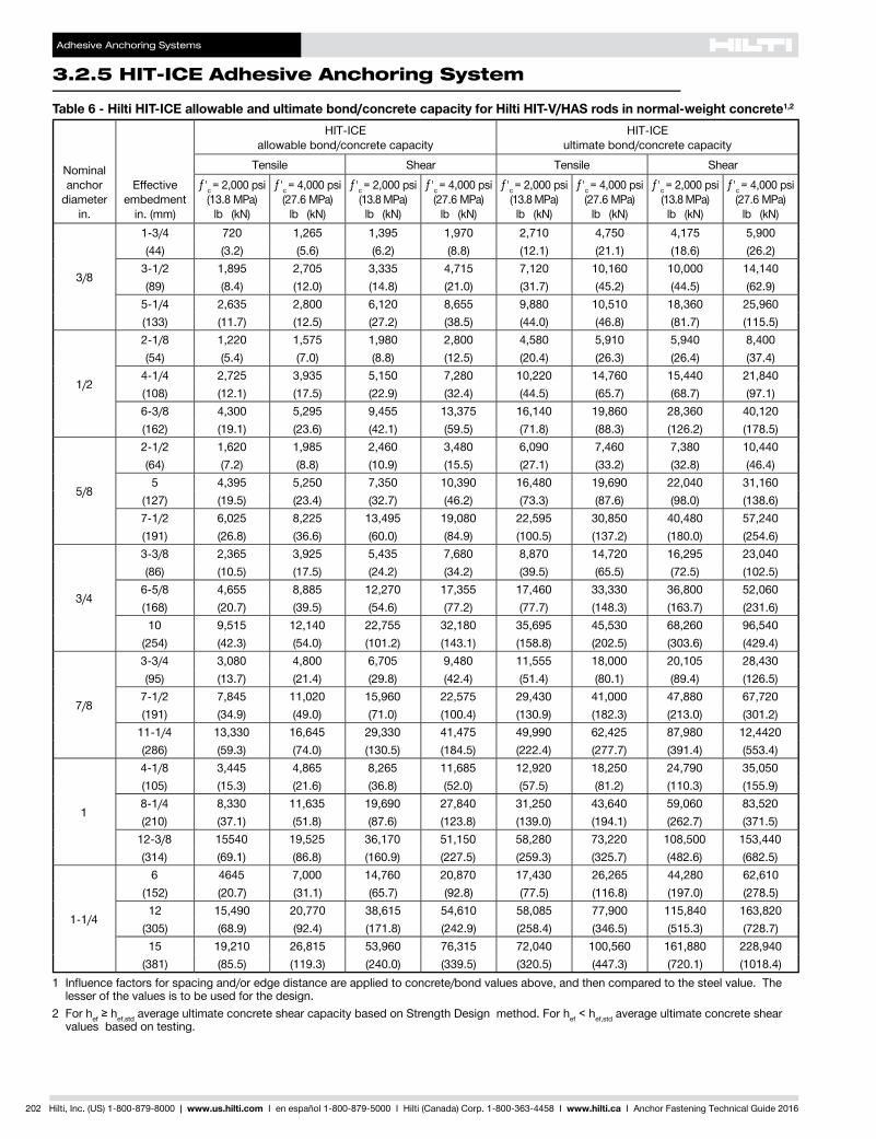
Table 6 - Hilti HIT-ICE allowable and ultimate bond/concrete capacity for Hilti HIT-V/HAS rods in normal-weight concrete1,2
Nominalanchor
diameterin.
Effective embedment
in. (mm)
HIT-ICEallowable bond/concrete capacity
HIT-ICEultimate bond/concrete capacity
Tensile Shear Tensile Shearƒ'c = 2,000 psi
(13.8 MPa)lb (kN)
ƒ'c = 4,000 psi(27.6 MPa)
lb (kN)
ƒ'c = 2,000 psi(13.8 MPa)lb (kN)
ƒ'c = 4,000 psi(27.6 MPa)
lb (kN)
ƒ'c = 2,000 psi(13.8 MPa)lb (kN)
ƒ'c = 4,000 psi(27.6 MPa)
lb (kN)
ƒ'c = 2,000 psi(13.8 MPa)lb (kN)
ƒ'c = 4,000 psi(27.6 MPa)
lb (kN)
3/8
1-3/4 720 1,265 1,395 1,970 2,710 4,750 4,175 5,900(44) (3.2) (5.6) (6.2) (8.8) (12.1) (21.1) (18.6) (26.2)
3-1/2 1,895 2,705 3,335 4,715 7,120 10,160 10,000 14,140(89) (8.4) (12.0) (14.8) (21.0) (31.7) (45.2) (44.5) (62.9)
5-1/4 2,635 2,800 6,120 8,655 9,880 10,510 18,360 25,960(133) (11.7) (12.5) (27.2) (38.5) (44.0) (46.8) (81.7) (115.5)
1/2
2-1/8 1,220 1,575 1,980 2,800 4,580 5,910 5,940 8,400(54) (5.4) (7.0) (8.8) (12.5) (20.4) (26.3) (26.4) (37.4)
4-1/4 2,725 3,935 5,150 7,280 10,220 14,760 15,440 21,840(108) (12.1) (17.5) (22.9) (32.4) (44.5) (65.7) (68.7) (97.1)6-3/8 4,300 5,295 9,455 13,375 16,140 19,860 28,360 40,120(162) (19.1) (23.6) (42.1) (59.5) (71.8) (88.3) (126.2) (178.5)
5/8
2-1/2 1,620 1,985 2,460 3,480 6,090 7,460 7,380 10,440(64) (7.2) (8.8) (10.9) (15.5) (27.1) (33.2) (32.8) (46.4)5 4,395 5,250 7,350 10,390 16,480 19,690 22,040 31,160
(127) (19.5) (23.4) (32.7) (46.2) (73.3) (87.6) (98.0) (138.6)7-1/2 6,025 8,225 13,495 19,080 22,595 30,850 40,480 57,240(191) (26.8) (36.6) (60.0) (84.9) (100.5) (137.2) (180.0) (254.6)
3/4
3-3/8 2,365 3,925 5,435 7,680 8,870 14,720 16,295 23,040(86) (10.5) (17.5) (24.2) (34.2) (39.5) (65.5) (72.5) (102.5)
6-5/8 4,655 8,885 12,270 17,355 17,460 33,330 36,800 52,060(168) (20.7) (39.5) (54.6) (77.2) (77.7) (148.3) (163.7) (231.6)10 9,515 12,140 22,755 32,180 35,695 45,530 68,260 96,540
(254) (42.3) (54.0) (101.2) (143.1) (158.8) (202.5) (303.6) (429.4)
7/8
3-3/4 3,080 4,800 6,705 9,480 11,555 18,000 20,105 28,430(95) (13.7) (21.4) (29.8) (42.4) (51.4) (80.1) (89.4) (126.5)
7-1/2 7,845 11,020 15,960 22,575 29,430 41,000 47,880 67,720(191) (34.9) (49.0) (71.0) (100.4) (130.9) (182.3) (213.0) (301.2)
11-1/4 13,330 16,645 29,330 41,475 49,990 62,425 87,980 12,4420(286) (59.3) (74.0) (130.5) (184.5) (222.4) (277.7) (391.4) (553.4)
1
4-1/8 3,445 4,865 8,265 11,685 12,920 18,250 24,790 35,050(105) (15.3) (21.6) (36.8) (52.0) (57.5) (81.2) (110.3) (155.9)8-1/4 8,330 11,635 19,690 27,840 31,250 43,640 59,060 83,520(210) (37.1) (51.8) (87.6) (123.8) (139.0) (194.1) (262.7) (371.5)
12-3/8 15540 19,525 36,170 51,150 58,280 73,220 108,500 153,440(314) (69.1) (86.8) (160.9) (227.5) (259.3) (325.7) (482.6) (682.5)
1-1/4
6 4645 7,000 14,760 20,870 17,430 26,265 44,280 62,610(152) (20.7) (31.1) (65.7) (92.8) (77.5) (116.8) (197.0) (278.5)12 15,490 20,770 38,615 54,610 58,085 77,900 115,840 163,820
(305) (68.9) (92.4) (171.8) (242.9) (258.4) (346.5) (515.3) (728.7)15 19,210 26,815 53,960 76,315 72,040 100,560 161,880 228,940
(381) (85.5) (119.3) (240.0) (339.5) (320.5) (447.3) (720.1) (1018.4)1 Influencefactorsforspacingand/oredgedistanceareappliedtoconcrete/bondvaluesabove,andthencomparedtothesteelvalue.The
lesser of the values is to be used for the design.2 For hef≥hef,std average ultimate concrete shear capacity based on Strength Design method. For hef < hef,std average ultimate concrete shear
values based on testing.

Adhesive Anchoring Systems
HIT-ICE Adhesive Anchoring System 3.2.5
3.2.5
Hilti, Inc. (US) 1-800-879-8000 | www.us.hilti.com I en español 1-800-879-5000 I Hilti (Canada) Corp. 1-800-363-4458 I www.hilti.ca I Anchor Fastening Technical Guide 2016 203
Table 7 - Allowable steel strength for Hilti HIT-V and HAS threaded rods1
Nominal anchor
diameterin.
HIT-VASTM A307 Grade A2
HAS-E ISO 898 Class 5.82
HAS-E B7 ASTM A193 Grade B7
HAS-R Stainless Steel ASTM F595 - AISI 304/316 SS
Tensile lb (kN)
Shear lb (kN)
Tensile lb (kN)
Shear lb (kN)
Tensile lb (kN)
Shear lb (kN)
Tensile lb (kN)
Shear lb (kN)
3/82,185 1,125 2,640 1,360 4,555 2,345 4,555 2,345(9.7) (5.0) (11.7) (6.0) (20.3) (10.4) (20.3) (10.4)
1/23,885 2,000 4,695 2,420 8,095 4,170 8,095 4,170(17.3) (8.9) (20.9) (10.8) (36.0) (18.5) (36.0) (18.5)
5/86,075 3,130 7,340 3,780 12,655 6,520 12,655 6,520(27.0) (13.9) (32.6) (16.8) (56.3) (29.0) (56.3) (29.0)
3/48,750 4,505 10,570 5,445 18,225 9,390 18,225 9,390(38.9) (20.0) (47.0) (24.2) (81.1) (41.8) (81.1) (41.8)
7/8- - 14,385 7,410 24,805 12,780 24,805 12,780- - (64.0) (33.0) (110.3) (56.8) (110.3) (56.8)
115,550 8,010 18,790 9,680 32,400 16,690 32,400 16,690(69.2) (35.6) (83.6) (43.1) (144.1) (74.2) (144.1) (74.2)
1-1/4- - 29,360 15,125 50,620 26,080 50,620 26,080- - (130.6) (67.3) (225.2) (116.0) (225.2) (116.0)
1 SteelstrengthasdefinedinAISCManualofSteelConstruction(ASD):Tensile = 0.33 x Fu x Nominal Area Shear = 0.17 x Fu x Nominal Area
2 HIT-V and HAS-E threaded rods are considered brittle steel elements. HIT-V does not comply with percent elongation requirements of ASTM A307 Grade A steel. HAS-E does not comply with % elongation requirements of ISO 898-1.
Table 8 - Ultimate steel strength for Hilti HIT-V and HAS threaded rods1
Nominal anchor
diameterin.
HIT-VASTM A307 Grade A2
HAS-E ISO 898 Class 5.82
HAS-E B7 ASTM A193 Grade B7
HAS-R Stainless Steel ASTM F593 - AISI 304/316 SS
Yield lb (kN)
Tensile lb (kN)
Shear lb (kN)
Yield lb (kN)
Tensile lb (kN)
Shear lb (kN)
Yield lb (kN)
Tensile lb (kN)
Shear lb (kN)
Yield lb (kN)
Tensile lb (kN)
Shear lb (kN)
3/82,905 4,970 2,980 4,495 6,005 3,600 8,140 10,350 6,210 5,040 8,280 4,970(12.9) (22.1) (13.3) (20.0) (26.7) (16.0) (36.2) (46.0) (27.6) (22.4) (36.8) (22.1)
1/25,320 8,835 5,300 8,230 10,675 6,405 14,900 18,405 11,040 9,225 14,725 8,835(23.7) (39.3) (23.6) (36.6) (47.5) (28.5) (66.3) (81.9) (49.1) (41.0) (65.5) (39.3)
5/88,475 13,805 8,285 13,110 16,680 10,010 23,730 28,765 17,260 14,690 23,010 13,805(37.7) (61.4) (36.9) (58.3) (74.2) (44.5) (105.6) (128.0) (76.8) (65.3) (102.4) (61.4)
3/412,545 19,880 11,930 19,400 24,025 14,415 35,125 41,420 24,850 15,055 28,165 16,900(55.8) (88.4) (53.1) (86.3) (106.9) (64.1) (156.2) (184.2) (110.5) (67.0) (125.3) (75.2)
7/8- - - 26,780 32,695 19,615 48,480 56,370 33,825 20,775 38,335 23,000- - - (119.1) (145.4) (87.3) (215.6) (250.7) (150.5) (92.4) (170.5) (102.3)
122,715 35,345 21,205 35,130 42,705 25,625 63,600 73,630 44,180 27,255 50,070 30,040(101.0) (157.2) (94.3) (156.3) (190.0) (114.0) (282.9) (327.5) (196.5) (121.2) (222.7) (133.6)
1-1/4- - - 56,210 66,730 40,035 101,755 115,050 69,030 43,610 78,235 46,940- - - (250.0) (296.8) (178.1) (452.6) (511.8) (307.1) (194.0) (348.0) (208.8)
1 SteelstrengthasdefinedinAISCManualofSteelConstruction2ndEd.(LRFD):Yield = Fy x Tensile stress Area Tensile = 0.75 x Fu x Nominal Area Shear = 0.45 x Fu x Nominal Area
2 HIT-V and HAS-E threaded rods are considered brittle steel elements. HIT-V does not comply with percent elongation requirements of ASTM A307 Grade A steel. HAS-E does not comply with % elongation requirements of ISO 898-1.

Adhesive Anchoring Systems
3.2.5 HIT-ICE Adhesive Anchoring System
204 Hilti, Inc. (US) 1-800-879-8000 | www.us.hilti.com I en español 1-800-879-5000 I Hilti (Canada) Corp. 1-800-363-4458 I www.hilti.ca I Anchor Fastening Technical Guide 2016
Table 9 - Hilti HIT-ICE allowable bond or concrete capacity and steel strength for Hilti HIS-N and HIS-RN inserts1
Thread size.
Effective embedment
in. (mm)
HIT-ICE allowablebond/concrete capacity Allowable bolt strength2
Tensilelb (kN)
Shearlb (kN)
ASTM A325carbon steel
ASTM F593stainless steel
Tensile1
lb (kN)Shear1
lb (kN)Tensile1
lb (kN)Shear1
lb (kN)
3/8-16 UNC4-3/8 2,750 1,605 4,370 2,250 3,645 1,875(110) (12.2) (7.1) (19.4) (10.0) (16.2) (8.3)
1/2-13 UNC5 4,195 3,040 7,775 4,005 6,480 3,335
(127) (18.7) (13.5) (34.6) (17.8) (28.8) (14.8)
5/8-11 UNC6-5/8 6,700 4,575 12,150 6,260 10,125 5,215(168) (29.8) (20.4) (54.0) (27.8) (45.0) (23.2)
3/4-10 UNC8-1/4 7,855 6,305 17,495 9,010 12,395 6,385(210) (34.9) (28.0) (77.8) (40.1) (55.1) (28.4)
Table 10 - Hilti HIT-ICE ultimate bond or concrete capacity and steel strength for Hilti HIS-N and HIS-RN inserts1
Thread size.
Effective embedment
in. (mm)
HIT-ICE ultimatebond/concrete capacity2 Ultimate bolt strength2
Tensilelb (kN)
Shearlb (kN)
ASTM A325carbon steel
ASTM F593stainless steel
Tensile1
lb (kN)Shear1
lb (kN)Tensile1
lb (kN)Shear1
lb (kN)
3/8-16 UNC4-3/8 11,000 6,425 9,935 5,960 8,280 4,970(110) (48.9) (28.6) (44.2) (26.5) (36.8) (22.1)
1/2-13 UNC5 16,790 12,170 17,665 10,600 14,720 8,835
(127) (74.7) (54.1) (78.6) (47.2) (65.5) (39.3)
5/8-11 UNC6-5/8 26,795 18,310 27,610 16,565 23,010 13,805(168) (119.2) (81.5) (122.8) (73.7) (102.4) (61.4)
3/4-10 UNC8-1/4 31,430 25,215 39,760 23,855 28,165 16,900(210) (139.8) (112.2) (176.9) (106.1) (125.3) (75.1)
1 Use lower value of either bond, concrete capacity or steel strength. Minimum concrete compressive strength ƒ'c is 2,000 psi.2 Steel values in accordance with AISC
ASTM A325 bolts Fy = 92 ksi , Fu = 120 ksi ASTM F593 (AISI 304/316) Fy = 65 ksi, Fu = 100 ksi for 3/8- through 5/8-in.
Fy = 45 ksi, Fu = 85 ksi for 3/4-in. Allowable load values Ultimate load values
Tension = 0.33 x Fu x Anom Tension = 0.75 x Fu x Anom Shear = 0.17 x Fu x Anom Shear = 0.45 x Fu x Anom

Adhesive Anchoring Systems
HIT-ICE Adhesive Anchoring System 3.2.5
3.2.5
Hilti, Inc. (US) 1-800-879-8000 | www.us.hilti.com I en español 1-800-879-5000 I Hilti (Canada) Corp. 1-800-363-4458 I www.hilti.ca I Anchor Fastening Technical Guide 2016 205
Table 11 - Hilti HIT-ICE allowable and ultimate bond/concrete capacity for Hilti HAS/HIT-V rods installed in 3,000 psi structural sand-lightweight concrete
Nominal anchor diameter
in.
Effective embedment
in. (mm)
Allowable bond/concrete capacity1
lb (kN)Ultimate bond/concrete capacity
lb (kN)Tensile Shear Tensile Shear
3/8
1-3/4(44) 745 (3.3) 1,285 (5.7) 2,980 (13.3) 5,150 (22.9)
3-1/2(89) 1,220 (5.4) 1,580 (7.0) 4,920 (21.9) 6,320 (28.1)
1/2
2-1/8(54) 975 (4.3) 2,130 (9.5) 3,900 (17.3) 8,520 (37.9)
4-1/4(108) 1,210 (5.4) 2,910 (12.9) 4,840 (21.5) 11,640 (51.8)
5/8 2-1/2(63) 1,200 15.3) 2,480 (11.0) 4,800 (21.4) 9,920 (44.1)
3/4 3-3/8(86) 1,760 (7.8) 4,000 (17.8) 7,040 (31.3) 15,985 (71.1)
1 Influencefactorsforspacingand/oredgedistanceareappliedtoallowableconcrete/bondvaluesabove,andthencomparedtotheallowablesteelvalue. The lesser of these values is to be used for design.
Table 12 - Allowable loads for anchorage of exterior sill plates with Hilti HIT-ICE1,2,3,4
Nominal anchor diameter
in.
Effective embedment
in. (mm)
edge distance Tension Shear lb (kN)
in. (mm) lb (kN) Load II to edge Load ⊥ to edge
1/2 4-1/4(108)
1-3/4 (45) 1,280 (5.3) 1,445 (6.4) 400 (1.8)2-3/4 (70) 1,800 (8.1) 2,100 (9.5) 845 (3.8)
5/8 5(127)
1-3/4 (45) 1,700 (7.6) 1,445 (6.4) 400 (1.8)2-3/4 (70) 2,725 (12.1) 2,455 (10.9) 960 (4.3)
1 Allowable loads calculated using a factor of safety of 4.2 Allowable loads are based on concrete capacity. The steel strength must be checked.3 A wood 2x4 exterior plate has a 1-3/4 inch edge distance. A 2x6 has a 2-3/4 inch edge distance.4 Minimum concrete compressive strength is 2,000 psi.
Table 13 - Allowable loads for anchorage to the top of grout-filled block walls with Hilti HIT-ICE1,2,3,4
Nominal anchor diameter
in.
Effective embedment
in. (mm)
Edge distance Tension Shear lb (kN)
in. (mm) lb (kN) Load II to edge Load ⊥ to edge
1/2 4-1/4(108)
1-3/4 (45) 1,120 (5.0) 1,425 (6.3) 560 (2.5)2-3/4 (70) 1,440 (6.4) 2,085 (9.3) 1,110 (4.9)
5/8 5(127)
1-3/4 (45) 1,475 (6.5) 1,800 (8.0) 680 (3.0)2-3/4 (70) 1,630 (7.2) 3,070 (13.7) 1,110 (4.9)
1 Allowable loads calculated using a factor of safety of 5.2 Allowable loads are based on masonry capacity. The steel strength must be checked.3 Minimum edge distance is 1-3/4 inches.4 Minimum masonry prism strength is 1,500 psi.
Adhesive Anchoring Systems
3.2.5 HIT-ICE Adhesive Anchoring System
206 Hilti, Inc. (US) 1-800-879-8000 | www.us.hilti.com I en español 1-800-879-5000 I Hilti (Canada) Corp. 1-800-363-4458 I www.hilti.ca I Anchor Fastening Technical Guide 2016
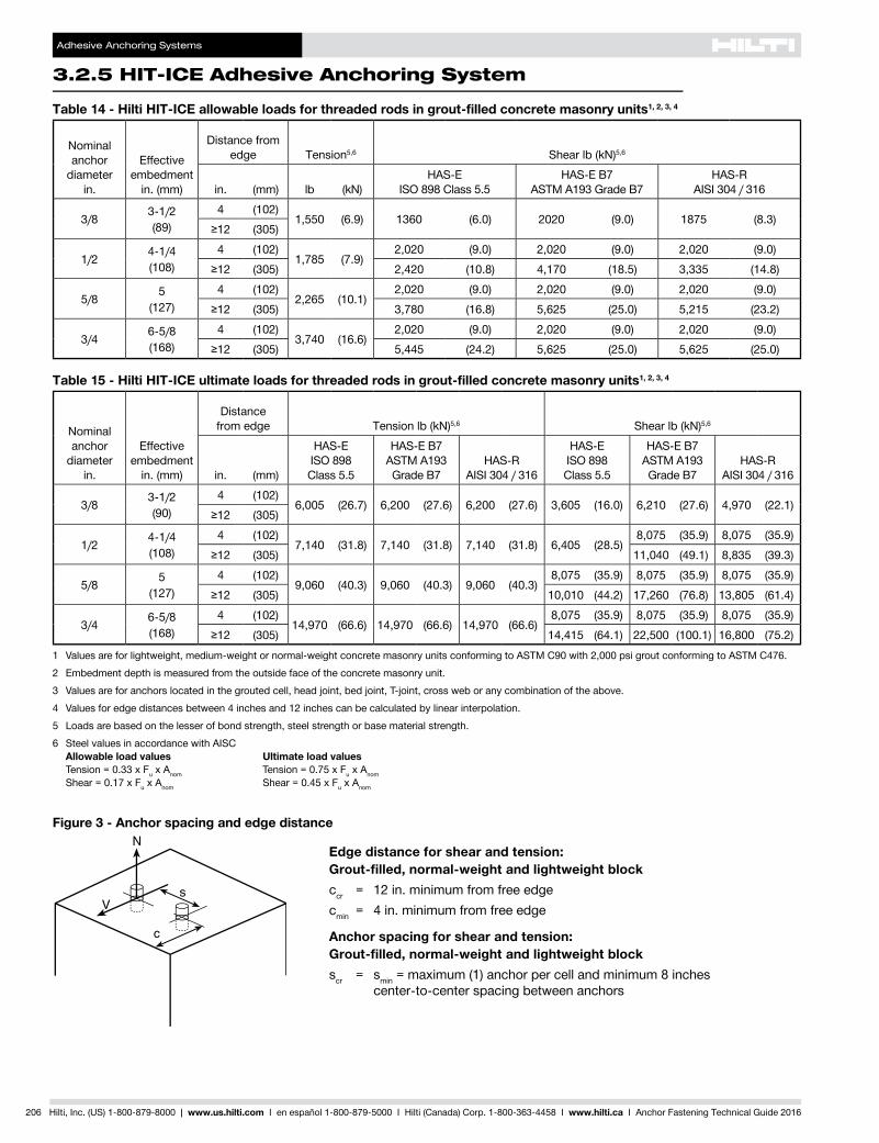
Table 14 - Hilti HIT-ICE allowable loads for threaded rods in grout-filled concrete masonry units1, 2, 3, 4
Nominal anchor
diameterin.
Effective embedment
in. (mm)
Distance from edge Tension5,6 Shear lb (kN)5,6
in. (mm) lb (kN)HAS-E
ISO 898 Class 5.5HAS-E B7
ASTM A193 Grade B7HAS-R
AISI 304 / 316
3/8 3-1/2(89)
4 (102)1,550 (6.9) 1360 (6.0) 2020 (9.0) 1875 (8.3)
≥12 (305)
1/2 4-1/4(108)
4 (102)1,785 (7.9)
2,020 (9.0) 2,020 (9.0) 2,020 (9.0)≥12 (305) 2,420 (10.8) 4,170 (18.5) 3,335 (14.8)
5/8 5(127)
4 (102)2,265 (10.1)
2,020 (9.0) 2,020 (9.0) 2,020 (9.0)≥12 (305) 3,780 (16.8) 5,625 (25.0) 5,215 (23.2)
3/4 6-5/8(168)
4 (102)3,740 (16.6)
2,020 (9.0) 2,020 (9.0) 2,020 (9.0)≥12 (305) 5,445 (24.2) 5,625 (25.0) 5,625 (25.0)
Edge distance for shear and tension: Grout-filled, normal-weight and lightweight blockccr = 12 in. minimum from free edgecmin = 4 in. minimum from free edge
Anchor spacing for shear and tension: Grout-filled, normal-weight and lightweight blockscr = smin = maximum (1) anchor per cell and minimum 8 inches
center-to-center spacing between anchors
Figure 3 - Anchor spacing and edge distance
Table 15 - Hilti HIT-ICE ultimate loads for threaded rods in grout-filled concrete masonry units1, 2, 3, 4
Nominal anchor
diameterin.
Effective embedment
in. (mm)
Distance from edge Tension lb (kN)5,6 Shear lb (kN)5,6
in. (mm)
HAS-E ISO 898 Class 5.5
HAS-E B7 ASTM A193 Grade B7
HAS-R AISI 304 / 316
HAS-E ISO 898 Class 5.5
HAS-E B7 ASTM A193 Grade B7
HAS-R AISI 304 / 316
3/8 3-1/2(90)
4 (102)6,005 (26.7) 6,200 (27.6) 6,200 (27.6) 3,605 (16.0) 6,210 (27.6) 4,970 (22.1)
≥12 (305)
1/2 4-1/4(108)
4 (102)7,140 (31.8) 7,140 (31.8) 7,140 (31.8) 6,405 (28.5)
8,075 (35.9) 8,075 (35.9)≥12 (305) 11,040 (49.1) 8,835 (39.3)
5/8 5(127)
4 (102)9,060 (40.3) 9,060 (40.3) 9,060 (40.3)
8,075 (35.9) 8,075 (35.9) 8,075 (35.9)≥12 (305) 10,010 (44.2) 17,260 (76.8) 13,805 (61.4)
3/4 6-5/8(168)
4 (102)14,970 (66.6) 14,970 (66.6) 14,970 (66.6)
8,075 (35.9) 8,075 (35.9) 8,075 (35.9)≥12 (305) 14,415 (64.1) 22,500 (100.1) 16,800 (75.2)
1 Values are for lightweight, medium-weight or normal-weight concrete masonry units conforming to ASTM C90 with 2,000 psi grout conforming to ASTM C476.2 Embedment depth is measured from the outside face of the concrete masonry unit.3 Values are for anchors located in the grouted cell, head joint, bed joint, T-joint, cross web or any combination of the above.4 Values for edge distances between 4 inches and 12 inches can be calculated by linear interpolation.5 Loads are based on the lesser of bond strength, steel strength or base material strength.6 Steel values in accordance with AISC
Allowable load values Ultimate load values Tension = 0.33 x Fu x Anom Tension = 0.75 x Fu x Anom Shear = 0.17 x Fu x Anom Shear = 0.45 x Fu x Anom

Adhesive Anchoring Systems
HIT-ICE Adhesive Anchoring System 3.2.5
3.2.5
Hilti, Inc. (US) 1-800-879-8000 | www.us.hilti.com I en español 1-800-879-5000 I Hilti (Canada) Corp. 1-800-363-4458 I www.hilti.ca I Anchor Fastening Technical Guide 2016 207
Table 16 - Hilti HIT-ICE ultimate bond capacity and steel strength for rebar in concrete
Rebarsize
Effective embedment
in. (mm)
Concrete compressive strengthGrade 60 rebar
ƒ'c = 2,000 psi (13.8 MPa) ƒ'c = 4,000 psi (27.6 MPa)
Ultimatebond
strengthlb (kN)
Embed. at ultimate load
= to yield strength1
in. (mm)
Embed. at ultimate load = to tensile strength1
in. (mm)
Ultimatebond
strengthlb (kN)
Embed. at ultimate load
= to yield strength1
in. (mm)
Embed. at ultimate load = to tensile strength1
in. (mm)
Yield strengthlb (kN)
Tensile strengthlb (kN)
#3
1-1/2 2,500
3-3/4
(95.3)
5-1/2
(139.7)
3,800
2-3/4
(69.9)
4-1/4
(108.0)
6,600
(29.4)
9,900
(44.0)
(38) (11.1) (16.9)3-1/2 6,300 8,200(89) (28.0) (36.5)7 12,600 16,500
(178) (56.0) (73.4)
#4
2 4,200
5-1/2
(139.7)
8
(203.2)
6,000
4-1/4
(108.0)
6-1/4
(158.8)
12,000
(53.4)
18,000
(80.1)
(51) (18.7) (26.7)4 9,000 11,800
(102) (40.0) (52.5)8 18,000 23,600
(203) (80.1) (105.0)
#5
2-1/2 5,600
7
(177.8)
10-1/4
(260.4)
6,900
5-1/4
(133.4)
8
(203.2)
18,600
(82.7)
27,900
(124.1)
(64) (24.9) (30.7)5 13,500 17,700
(127) (60.1) (78.7)10 27,000 35,300
(254) (120.1) (157.0)
#6
3-1/2 10,200
8-1/2
(215.9)
12-3/4
(323.9)
12,800
6-1/2
(165.1)
9-3/4
(247.7)
26,400
(117.4)
39,600
(176.2)
(90) (45.4) (56.9)7 22,100 28,900
(178) (98.3) (128.6)14 44,200 57,700
(356) (196.6) (256.7)
#7
3-3/4 10,700
10
(254.0)
15
(381)
15,800
7-3/4
(196.9)
11-1/2
(292.1)
36,000
(160.1)
54,000
(240.2)
(95) (47.6) (70.3)7-1/2 27,100 35,300(190) (120.6) (157.0)15 54,200 70,700
(380) (241.1) (314.5)
#8
4 14,100
11-3/4
(298.5)
17-1/2
(444.5)
18,100
9
(228.6)
13-1/2
(342.9)
47,450
(211.1)
71,100
(316.3)
(102) (62.7) (80.5)8 32,500 42,400
(204) (144.6) (188.6)16 65,000 84,800
(408) (289.1) (377.2)
#9
5 16,700
12-3/4
(323.9)
19
(482.6)
21,800
10
(254.0)
15-3/4
(400.1)
60,000
(266.9)
90,000
(400.4)
(127) (74.3) (97.0)10 47,400 61,800
(254) (210.9) (274.9)18 85,300 111,300
(457) (379.4) (495.1)
#10
6 23,300
15-1/2
(393.7)
23
(584.2)
32,400
12
(304.8)
17-3/4
(450.9)
76,200
(339.0)
114,300
(508.5)
(152) (103.6) (144.1)12 59,600 77,700
(304) (265.1) (345.6)20 99,300 129,600
(508) (441.7) (576.5)
#11
7 32,000
17-1/4
(438.2)
26
(660.4)
41,300
13-1/2
(342.9)
20
(508.0)
93,600
(416.4)
140,400
(624.6)
(178) (142.3) (183.7)14 75,800 99,000
(356) (337.2) (440.4)20 108,400 141,400
(508) (482.2) (629.0)1 Based on comparison of average ultimate adhesive bond test values versus minimum yield and ultimate tensile strength of rebar with no
consideration of spacing or edge distance; for more information, contact Hilti.

Adhesive Anchoring Systems
3.2.5 HIT-ICE Adhesive Anchoring System
208 Hilti, Inc. (US) 1-800-879-8000 | www.us.hilti.com I en español 1-800-879-5000 I Hilti (Canada) Corp. 1-800-363-4458 I www.hilti.ca I Anchor Fastening Technical Guide 2016
Table 17 - Hilti HIT-ICE bond capacity and steel strength for CA rebar in concrete1,2 c
RebarSize
HIT-ICE Tensile Bond Strength2,3,4Strength Propertiesof Metric Rebar 2,3
EmbedmentDepth(mm)
ƒ'c = 14 MPa ƒ'c = 28 MPa ƒy = 400 MPa
UltimateBond(kN)
AllowableBond(kN)
UltimateBond(kN)
AllowableBond(kN)
YieldStrength
(kN)
TensileStrength
(kN)
10M40 11.1 2.8 16.9 4.290 28.0 7.0 36.5 9.1 40 60180 56.0 14.0 73.4 18.3
15M65 24.9 6.2 30.7 7.7130 60.1 15.0 78.7 19.7 80 120250 120 30.0 157 39.2
20M90 45.4 11.3 56.9 14.2180 98.3 24.6 129 32.2 120 180355 197 49.2 257 64.2
25M100 62.7 15.7 80.5 20.1200 145 36.2 189 47.2 200 300405 289 72.2 377 94.2
30M125 74.3 18.6 97.0 24.2250 211 52.8 275 68.8 280 420455 379 94.8 495 124
35M180 142 35.5 184 46.0355 337 84.2 440 110 400 600510 482 120 629 157
1 Use lesser value of bond strength or rebar’s steel strength for tensile capacity.2 For anchoring spacing and edge distance guidelines, please refer to the following pages of this HIT-ICE Injection Adhesive Anchor section.
Adhesive Anchoring Systems
HIT-ICE Adhesive Anchoring System 3.2.5
3.2.5
Hilti, Inc. (US) 1-800-879-8000 | www.us.hilti.com I en español 1-800-879-5000 I Hilti (Canada) Corp. 1-800-363-4458 I www.hilti.ca I Anchor Fastening Technical Guide 2016 209
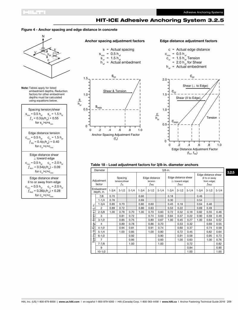
Anchor spacing adjustment factors
s = Actual spacing smin = 0.5 hef scr = 1.5 hef hef = Actual embedment
Edge distance adjustment factors
c = Actual edge distance cmin = 0.5 hef ccr = 1.5 hef Tension = 2.0 hef for Shear hef = Actual embedment
Table 18 - Load adjustment factors for 3/8-in. diameter anchorsDiameter 3/8-in.
Adjustmentfactor
Spacingtension/shear
ƒA
Edge distancetension
ƒRN
Edge distance shear (⊥ toward edge)
ƒRV1
Edge distance shear(II to or away from edge)
ƒRV2
Embedmentdepth, in. 1-3/4 3-1/2 5-1/4 1-3/4 3-1/2 5-1/4 1-3/4 3-1/2 5-1/4 1-3/4 3-1/2 5-1/4
Spac
ing
(s)/E
dge
dist
ance
(c),
in.
7/8 0.70 0.60 0.18 0.461-1/4 0.76 0.69 0.30 0.541-3/4 0.85 0.70 0.80 0.60 0.45 0.18 0.64 0.46
2 0.89 0.72 0.86 0.63 0.53 0.22 0.69 0.492-5/8 1.00 0.78 0.70 1.00 0.70 0.60 0.72 0.32 0.18 0.82 0.55 0.46
3 0.81 0.72 0.74 0.63 0.84 0.37 0.22 0.90 0.59 0.493-1/2 0.85 0.75 0.80 0.67 1.00 0.45 0.27 1.00 0.64 0.52
4 0.89 0.78 0.86 0.70 0.53 0.32 0.69 0.554-1/2 0.94 0.81 0.91 0.74 0.60 0.37 0.74 0.595-1/4 1.00 0.85 1.00 0.80 0.72 0.45 0.82 0.646-1/2 0.92 0.90 0.91 0.58 0.95 0.73
7 0.95 0.93 1.00 0.63 1.00 0.767-7/8 1.00 1.00 0.72 0.82
9 0.84 0.9010-1/2 1.00 1.00
Spacing tension/shear smin = 0.5 hef scr = 1.5 hef
ƒA = 0.3(s/hef) + 0.55 for scr>s>smin
Edge distance tension cmin = 0.5 hef ccr = 1.5 hef
ƒRN = 0.4(c/hef) + 0.40 for ccr>c>cmin
Edge distance shear ⊥ toward edge
cmin = 0.5 hef ccr = 2.0 hef ƒRV1 = 0.54(c/hef) – 0.09
for ccr>c>cmin
Edge distance shear II to or away from edge
cmin = 0.5 hef ccr = 2.0 hef ƒRV2 = 0.36(c/hef) + 0.28
for ccr>c>cmin
Figure 4 - Anchor spacing and edge distance in concrete
Note: Tables apply for listed embedment depths. Reduction factors for other embedment depths must be calculated using equations below.

Adhesive Anchoring Systems
3.2.5 HIT-ICE Adhesive Anchoring System
210 Hilti, Inc. (US) 1-800-879-8000 | www.us.hilti.com I en español 1-800-879-5000 I Hilti (Canada) Corp. 1-800-363-4458 I www.hilti.ca I Anchor Fastening Technical Guide 2016
Table 20 - Load adjustment factors for 5/8-in. and 3/4-in. diameter anchorsDiameter 5/8-in. 3/4-in.
Adjustmentfactor
Spacingtension/shear
ƒA
Edge distancetension
ƒRN
Edge distance shear
(⊥ toward edge)ƒRV1
Edge distance shear
(II to or away from edge)
ƒRV2
Spacingtension/shear
ƒA
Edge distancetension
ƒRN
Edge distance shear
(⊥ toward edge)ƒRV1
Edge distance shear
(II to or away from edge)
ƒRV2
Embedmentdepth, in. 2-1/2 5 7-1/2 2-1/2 5 7-1/2 2-1/2 5 7-1/2 2-1/2 5 7-1/2 3-3/8 6-5/8 10 3-3/8 6-5/8 10 3-3/8 6-5/8 10 3-3/8 6-5/8 10
Spac
ing
(s)/E
dge
dist
ance
(c),
in.
1-1/4 0.70 0.60 0.18 0.461-11/16 0.75 0.67 0.27 0.52 0.70 0.60 0.18 0.46
2 0.79 0.72 0.34 0.57 0.73 0.64 0.23 0.492-1/2 0.85 0.70 0.80 0.60 0.45 0.18 0.64 0.46 0.77 0.70 0.31 0.55
3 0.91 0.73 0.88 0.64 0.56 0.23 0.71 0.50 0.82 0.76 0.39 0.603-5/16 0.95 0.75 0.93 0.67 0.63 0.27 0.76 0.52 0.84 0.70 0.79 0.60 0.44 0.18 0.63 0.463-3/4 1.00 0.78 0.70 1.00 0.70 0.60 0.72 0.32 0.18 0.82 0.55 0.46 0.88 0.72 0.84 0.63 0.51 0.22 0.68 0.48
4 0.79 0.71 0.72 0.61 0.77 0.34 0.20 0.86 0.57 0.47 0.91 0.73 0.87 0.64 0.55 0.24 0.71 0.504-1/2 0.82 0.73 0.76 0.64 0.88 0.40 0.23 0.93 0.60 0.50 0.95 0.75 0.93 0.67 0.63 0.28 0.76 0.52
5 0.85 0.75 0.80 0.67 1.00 0.45 0.27 1.00 0.64 0.52 0.99 0.78 0.70 0.99 0.70 0.60 0.71 0.32 0.18 0.81 0.55 0.465-1/16 0.85 0.75 0.81 0.67 0.46 0.27 0.64 0.52 1.00 0.78 0.70 1.00 0.71 0.60 0.72 0.32 0.18 0.82 0.56 0.465-1/2 0.88 0.77 0.84 0.69 0.50 0.31 0.68 0.54 0.80 0.72 0.73 0.62 0.79 0.36 0.21 0.87 0.58 0.48
6 0.91 0.79 0.88 0.72 0.56 0.34 0.71 0.57 0.82 0.73 0.76 0.64 0.87 0.40 0.23 0.92 0.61 0.506-3/4 0.96 0.82 0.94 0.76 0.64 0.40 0.77 0.60 0.86 0.75 0.81 0.67 1.00 0.46 0.27 1.00 0.65 0.527-1/2 1.00 0.85 1.00 0.80 0.72 0.45 0.82 0.64 0.89 0.78 0.85 0.70 0.52 0.32 0.69 0.55
8 0.87 0.83 0.77 0.49 0.86 0.66 0.91 0.79 0.88 0.72 0.56 0.34 0.71 0.578-1/2 0.89 0.85 0.83 0.52 0.89 0.69 0.93 0.81 0.91 0.74 0.60 0.37 0.74 0.59
9 0.91 0.88 0.88 0.56 0.93 0.71 0.96 0.82 0.94 0.76 0.64 0.40 0.77 0.609-15/16 0.95 0.93 0.98 0.63 1.00 0.76 1.00 0.85 1.00 0.80 0.72 0.45 0.82 0.64
10 0.95 0.93 1.00 0.63 0.76 0.85 0.80 0.73 0.45 0.82 0.6411-1/4 1.00 1.00 0.72 0.82 0.89 0.85 0.83 0.52 0.89 0.69
12 0.77 0.86 0.91 0.88 0.89 0.56 0.93 0.7113-1/4 0.86 0.92 0.95 0.93 1.00 0.63 1.00 0.76
14 0.92 0.95 0.97 0.96 0.67 0.7815 1.00 1.00 1.00 1.00 0.72 0.8216 0.77 0.8618 0.88 0.9320 1.00 1.00
Table 19 - Load adjustment factors for 1/2-in. diameter anchorsDiameter 1/2-in.
Adjustmentfactor
Spacingtension/shear
ƒA
Edge distancetension
ƒRN
Edge distance shear (⊥ toward edge)
ƒRV1
Edge distance shear(II to or away from edge)
ƒRV2
Embedmentdepth, in. 2-1/8 4-1/4 6-3/8 2-1/8 4-1/4 6-3/8 2-1/8 4-1/4 6-3/8 2-1/8 4-1/4 6-3/8
Spac
ing
(s)/E
dge
dist
ance
(c),
in.
1-1/16 0.70 0.60 0.18 0.461-1/2 0.76 0.68 0.29 0.53
2 0.83 0.78 0.42 0.622-1/8 0.85 0.70 0.80 0.60 0.45 0.18 0.64 0.462-3/4 0.94 0.74 0.92 0.66 0.61 0.26 0.75 0.51
3 0.97 0.76 0.96 0.68 0.67 0.29 0.79 0.533-3/16 1.00 0.78 0.70 1.00 0.70 0.60 0.72 0.32 0.18 0.82 0.55 0.46
4 0.83 0.74 0.78 0.65 0.93 0.42 0.25 0.96 0.62 0.514-1/4 0.85 0.75 0.80 0.67 1.00 0.45 0.27 1.00 0.64 0.52
5 0.90 0.79 0.87 0.71 0.55 0.33 0.70 0.566 0.97 0.83 0.96 0.78 0.67 0.42 0.79 0.62
6-3/8 1.00 0.85 1.00 0.80 0.72 0.45 0.82 0.647 0.88 0.84 0.80 0.50 0.87 0.68
7-1/2 0.90 0.87 0.86 0.55 0.92 0.708-1/2 0.95 0.93 1.00 0.63 1.00 0.76
9 0.97 0.96 0.67 0.799-9/16 1.00 1.00 0.72 0.82
10 0.76 0.8411 0.84 0.90
12-3/4 1.00 1.00
Note: Tables apply for listed embedment depths. Reduction factors for other embedment depths must be calculated using equations below.
Spacing tension/shear smin = 0.5 hef scr = 1.5 hef
ƒA = 0.3(s/hef) + 0.55 for scr>s>smin
Edge distance tension cmin = 0.5 hef ccr = 1.5 hef
ƒRN = 0.4(c/hef) + 0.40 for ccr>c>cmin
Edge distance shear ⊥ toward edge
cmin = 0.5 hef ccr = 2.0 hef ƒRV1 = 0.54(c/hef) – 0.09
for ccr>c>cmin
Edge distance shear II to or away from edge
cmin = 0.5 hef ccr = 2.0 hef ƒRV2 = 0.36(c/hef) + 0.28
for ccr>c>cmin
Adhesive Anchoring Systems
HIT-ICE Adhesive Anchoring System 3.2.5
3.2.5
Hilti, Inc. (US) 1-800-879-8000 | www.us.hilti.com I en español 1-800-879-5000 I Hilti (Canada) Corp. 1-800-363-4458 I www.hilti.ca I Anchor Fastening Technical Guide 2016 211
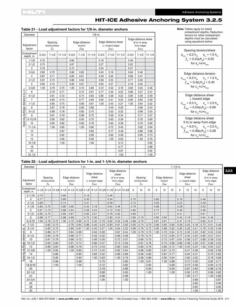
Table 21 - Load adjustment factors for 7/8-in. diameter anchorsDiameter 7/8-in.
Adjustmentfactor
Spacingtension/shear
ƒA
Edge distancetension
ƒRN
Edge distance shear (⊥ toward edge)
ƒRV1
Edge distance shear(II to or away from edge)
ƒRV2
Embedmentdepth, in. 3-3/4 7-1/2 11-1/4 3-3/4 7-1/2 11-1/4 3-3/4 7-1/2 11-1/4 3-3/4 7-1/2 11-1/4
Spac
ing
(s)/E
dge
dist
ance
(c),
in.
1-7/8 0.70 0.60 0.18 0.462-1/2 0.75 0.67 0.27 0.52
3 0.79 0.72 0.34 0.573-3/4 0.85 0.70 0.80 0.60 0.45 0.18 0.64 0.46
4 0.87 0.71 0.83 0.61 0.49 0.20 0.66 0.474-1/2 0.91 0.73 0.88 0.64 0.56 0.23 0.71 0.50
5 0.95 0.75 0.93 0.67 0.63 0.27 0.76 0.525-5/8 1.00 0.78 0.70 1.00 0.70 0.60 0.72 0.32 0.18 0.82 0.55 0.46
6 0.79 0.71 0.72 0.61 0.77 0.34 0.20 0.86 0.57 0.476-1/2 0.81 0.72 0.75 0.63 0.85 0.38 0.22 0.90 0.59 0.49
7 0.83 0.74 0.77 0.65 0.92 0.41 0.25 0.95 0.62 0.507-1/2 0.85 0.75 0.80 0.67 1.00 0.45 0.27 1.00 0.64 0.52
8 0.87 0.76 0.83 0.68 0.49 0.29 0.66 0.548-1/2 0.89 0.78 0.85 0.70 0.52 0.32 0.69 0.55
9 0.91 0.79 0.88 0.72 0.56 0.34 0.71 0.579-15/16 0.95 0.82 0.93 0.75 0.63 0.39 0.76 0.60
10 0.95 0.82 0.93 0.76 0.63 0.39 0.76 0.6011-1/4 1.00 0.85 1.00 0.80 0.72 0.45 0.82 0.64
12 0.87 0.83 0.77 0.49 0.86 0.6614 0.92 0.90 0.92 0.58 0.95 0.7315 0.95 0.93 1.00 0.63 1.00 0.76
16-7/8 1.00 1.00 0.72 0.8218 0.77 0.8620 0.87 0.92
22-1/2 1.00 1.00
Table 22 - Load adjustment factors for 1-in. and 1-1/4-in. diameter anchorsDiameter 1-in. 1-1/4-in.
Adjustmentfactor
Spacingtension/shear
ƒA
Edge distancetension
ƒRN
Edge distance shear
(⊥ toward edge)ƒRV1
Edge distance shear
(II to or awayfrom edge)
ƒRV2
Spacingtension/shear
ƒA
Edge distancetension
ƒRN
Edge distance shear
(⊥ toward edge)ƒRV1
Edge distance shear
(II to or awayfrom edge)
ƒRV2
Embedmentdepth, in. 4-1/8 8-1/4 12-3/8 4-1/8 8-1/4 12-3/8 4-1/8 8-1/4 12-3/8 4-1/8 8-1/4 12-3/8 6 12 15 6 12 15 6 12 15 6 12 15
Spac
ing
(s)/E
dge
dist
ance
(c),
in.
2-1/16 0.70 0.60 0.18 0.463 0.77 0.69 0.30 0.54 0.70 0.60 0.18 0.46
3-1/2 0.80 0.74 0.37 0.59 0.73 0.63 0.23 0.494-1/8 0.85 0.70 0.80 0.60 0.45 0.18 0.64 0.46 0.76 0.68 0.28 0.53
5 0.91 0.73 0.88 0.64 0.56 0.24 0.72 0.50 0.80 0.73 0.36 0.585-1/2 0.95 0.75 0.93 0.67 0.63 0.27 0.76 0.52 0.83 0.77 0.41 0.61
6 0.99 0.77 0.98 0.69 0.70 0.30 0.80 0.54 0.85 0.70 0.80 0.60 0.45 0.18 0.64 0.466-3/16 1.00 0.78 0.70 1.00 0.70 0.60 0.72 0.32 0.18 0.82 0.55 0.46 0.86 0.70 0.81 0.61 0.47 0.19 0.65 0.477-1/2 0.82 0.73 0.76 0.64 0.89 0.40 0.24 0.93 0.61 0.50 0.93 0.74 0.70 0.90 0.65 0.60 0.59 0.25 0.18 0.73 0.51 0.468-1/4 0.85 0.75 0.80 0.67 1.00 0.45 0.27 1.00 0.64 0.52 0.96 0.76 0.72 0.95 0.68 0.62 0.65 0.28 0.21 0.78 0.53 0.48
9 0.88 0.77 0.84 0.69 0.50 0.30 0.67 0.54 1.00 0.78 0.73 1.00 0.70 0.64 0.72 0.32 0.23 0.82 0.55 0.509-1/2 0.90 0.78 0.86 0.71 0.53 0.32 0.69 0.56 0.79 0.74 0.72 0.65 0.77 0.34 0.25 0.85 0.57 0.51
10 0.91 0.79 0.88 0.72 0.56 0.35 0.72 0.57 0.80 0.75 0.73 0.67 0.81 0.36 0.27 0.88 0.58 0.5210-1/2 0.93 0.80 0.91 0.74 0.60 0.37 0.74 0.59 0.81 0.76 0.75 0.68 0.86 0.38 0.29 0.91 0.60 0.53
12 0.99 0.84 0.98 0.79 0.70 0.43 0.80 0.63 0.85 0.79 0.80 0.72 1.00 0.45 0.34 1.00 0.64 0.5712-3/8 1.00 0.85 1.00 0.80 0.72 0.45 0.82 0.64 0.86 0.80 0.81 0.73 0.47 0.36 0.65 0.58
14 0.89 0.85 0.83 0.52 0.89 0.69 0.90 0.83 0.87 0.77 0.54 0.41 0.70 0.6216-1/2 0.95 0.93 1.00 0.63 1.00 0.76 0.96 0.88 0.95 0.84 0.65 0.50 0.78 0.68
18 0.99 0.98 0.70 0.80 1.00 0.91 1.00 0.88 0.72 0.56 0.82 0.7118-9/16 1.00 1.00 0.72 0.82 0.92 0.90 0.75 0.58 0.84 0.73
20 0.78 0.86 0.95 0.93 0.81 0.63 0.88 0.7622-1/2 0.89 0.93 1.00 1.00 0.92 0.72 0.96 0.82
24 0.96 0.98 1.00 0.77 1.00 0.8624-3/4 1.00 1.00 0.80 0.87
26 0.85 0.9028 0.92 0.9530 1.00 1.00
Note: Tables apply for listed embedment depths. Reduction factors for other embedment depths must be calculated using equations below.
Spacing tension/shear smin = 0.5 hef scr = 1.5 hef
ƒA = 0.3(s/hef) + 0.55 for scr>s>smin
Edge distance tension cmin = 0.5 hef ccr = 1.5 hef
ƒRN = 0.4(c/hef) + 0.40 for ccr>c>cmin
Edge distance shear ⊥ toward edge
cmin = 0.5 hef ccr = 2.0 hef ƒRV1 = 0.54(c/hef) – 0.09
for ccr>c>cmin
Edge distance shear II to or away from edge
cmin = 0.5 hef ccr = 2.0 hef ƒRV2 = 0.36(c/hef) + 0.28
for ccr>c>cmin
Adhesive Anchoring Systems
3.2.5 HIT-ICE Adhesive Anchoring System
212 Hilti, Inc. (US) 1-800-879-8000 | www.us.hilti.com I en español 1-800-879-5000 I Hilti (Canada) Corp. 1-800-363-4458 I www.hilti.ca I Anchor Fastening Technical Guide 2016
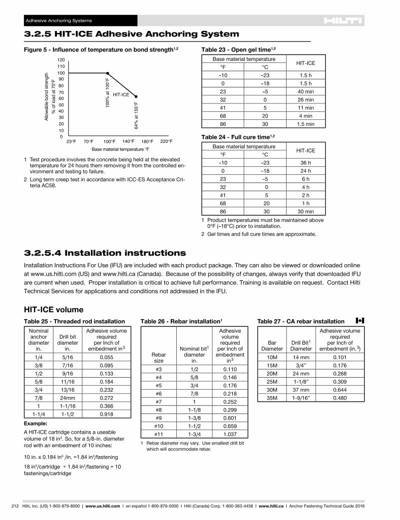
Table 23 - Open gel time1,2
Base material temperatureHIT-ICE
°F °C–10 –23 1.5 h0 –18 1.5 h23 –5 40 min32 0 26 min41 5 11 min68 20 4 min86 30 1.5 min
Table 24 - Full cure time1,2
Base material temperatureHIT-ICE
°F °C–10 –23 36 h0 –18 24 h23 –5 6 h32 0 4 h41 5 2 h68 20 1 h86 30 30 min
1 Product temperatures must be maintained above 0°F (–18°C) prior to installation.
2 Gel times and full cure times are approximate.
Base material temperature °F
Allo
wab
le b
ond
stre
ngth
% o
f loa
d at
70°
FFigure 5 - Influence of temperature on bond strength1,2
1 Test procedure involves the concrete being held at the elevated temperature for 24 hours them removing it from the controlled en-vironment and testing to failure.
2 Long term creep test in accordance with ICC-ES Acceptance Cri-teria AC58.
3.2.5.4 Installation instructionsInstallation Instructions For Use (IFU) are included with each product package. They can also be viewed or downloaded online at www.us.hilti.com (US) and www.hilti.ca (Canada). Because of the possibility of changes, always verify that downloaded IFU are current when used. Proper installation is critical to achieve full performance. Training is available on request. Contact Hilti Technical Services for applications and conditions not addressed in the IFU.
HIT-ICE volumeTable 25 - Threaded rod installation
Nominal anchor
diameterin.
Drill bitdiameter
in.
Adhesive volumerequired
per Inch of embedment in 3
1/4 5/16 0.0553/8 7/16 0.0951/2 9/16 0.1335/8 11/16 0.1843/4 13/16 0.2327/8 24mm 0.2721 1-1/16 0.366
1-1/4 1-1/2 0.918
Example:A HIT-ICE cartridge contains a useable volume of 18 in3. So, for a 5/8-in. diameter rod with an embedment of 10 inches:
10 in. x 0.184 in3 /in. =1.84 in3/fastening
18 in3/cartridge ÷ 1.84 in3/fastening = 10 fastenings/cartridge
Table 26 - Rebar installation1
Rebarsize
Nominal bit1diameter
in.
Adhesive volumerequired
per Inch of embedment
in 3
#3 1/2 0.110#4 5/8 0.146#5 3/4 0.176#6 7/8 0.218#7 1 0.252#8 1-1/8 0.299#9 1-3/8 0.601#10 1-1/2 0.659#11 1-3/4 1.037
1 Rebar diameter may vary. Use smallest drill bit which will accommodate rebar.
Table 27 - CA rebar installation c
BarDiameter
Drill Bit1Diameter
Adhesive volumerequired
per Inch of embedment (in. 3)
10M 14 mm 0.10115M 3/4” 0.17620M 24 mm 0.26825M 1-1/8” 0.30930M 37 mm 0.64435M 1-9/16” 0.480

Adhesive Anchoring Systems
HIT-ICE Adhesive Anchoring System 3.2.5
3.2.5
Hilti, Inc. (US) 1-800-879-8000 | www.us.hilti.com I en español 1-800-879-5000 I Hilti (Canada) Corp. 1-800-363-4458 I www.hilti.ca I Anchor Fastening Technical Guide 2016 213
HIT-ICE DispenserHIT-ICE CartridgeHIT-ICE Mixer
3.2.5.5 Ordering information1
HIT-ICE Cartridge
Description ContentsHIT-ICE Cartridge 10 oz (297 ml) 24 Cartridges, 24 Mixers
HIT Filler Tube
HIT-ICE MixerDescription Notes Qty/PkgHIT-M2 Mixer for HIT-ICE only For use with HIT-ICE cartridges 1
MD 1000 Dispenser
Description Notes Qty/PkgMD 1000 Dispenser For use with HIT-ICE cartridges 1
For ordering information on anchor rods and inserts, dispensers, hole cleaning equipment and other accessories, see section 3.2.9.