higher-order mode suppression in twisted single-ring ... · single-ring hollow-core photonic...
TRANSCRIPT
Higher-order mode suppression in twistedsingle-ring hollow-core photonic crystal fibersN. N. EDAVALATH,* M. C. GÜNENDI, R. BERAVAT, G. K. L. WONG, M. H. FROSZ,J.-M. MÉNARD, AND P. ST.J. RUSSELL
Max Planck Institute for the Science of Light, Staudtstr. 2, 91058 Erlangen, Germany*Corresponding author: [email protected]
Received 10 January 2017; revised 24 April 2017; accepted 26 April 2017; posted 3 May 2017 (Doc. ID 293271); published 17 May 2017
A hollow-core single-ring photonic crystal fiber (SR-PCF)consists of a ring of capillaries arranged around a centralhollow core. Spinning the preform during drawing introdu-ces a continuous helical twist, offering a novel means ofcontrolling the modal properties of hollow-core SR-PCF.For example, twisting geometrically increases the effectiveaxial propagation constant of the LP01-like modes of thecapillaries, providing a means of optimizing the suppres-sion of HOMs, which occurs when the LP11-like core modephase-matches to the LP01-like modes of the surroundingcapillaries. (In a straight fiber, optimum suppression occursfor a capillary-to-core diameter ratio d∕D � 0.682.)Twisting also introduces circular birefringence (to be stud-ied in a future Letter) and has a remarkable effect on thetransverse intensity profiles of the higher-order core modes,forcing the two-lobed LP11-like mode in the untwisted fiberto become three-fold symmetric in the twisted case. Thesephenomena are explored by means of extensive numericalmodeling, an analytical model, and a series of experiments.Prism-assisted side-coupling is used to measure the losses,refractive indices, and near-field patterns of individual fibermodes in both the straight and twisted cases. © 2017Optical Society of America
OCIS codes: (060.2280) Fiber design and fabrication; (060.2430)
Fibers, single-mode; (060.2310) Fiber optics; (060.2270) Fiber char-
acterization; (060.2300) Fiber measurements; (060.5295) Photonic
crystal fibers.
https://doi.org/10.1364/OL.42.002074
A hollow-core photonic crystal fiber (HC-PCF) has opened upa wide range of new applications for optical fibers, for example,in the delivery of high-power laser light [1], pulse compression[2], and enhanced gas-light interactions [3,4]. HC-PCFs areprimarily divided into two types based on their guidancemechanism, namely, photonic bandgap and anti-resonant re-flection (ARR) [5]. A common example of an ARR-PCF iskagomé-PCF [6], which offers relatively low transmission lossover broad spectral ranges in the visible and near-infrared.Stacking a kagomé-PCF preform requires a large number of
capillaries, but renders the production cumbersome andtime-consuming. In addition, optical resonances in the manystruts and junctions in the extended kagomé-PCF claddingphase-match to the core mode at certain wavelengths, givingrise to loss peaks that degrade the flatness of the transmissionspectrum.
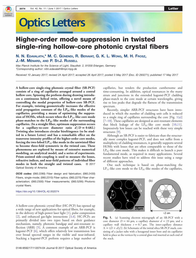
Recently, simpler ARR-PCF structures have been intro-duced in which the number of cladding unit cells is reducedto a single ring of capillaries surrounding the core [Fig. 1(a)][7–10]. These capillaries are designed as anti-resonant elementsthat block leakage of the LP01-like core mode [10,11].Impressively low losses can be reached with these very simplestructures [9].
Although an SR-PCF is easier to fabricate than the structur-ally more complex kagomé-PCF, and does not suffer from amultiplicity of cladding resonances, it generally supports severalHOMs with losses that are often comparable to those of theLP01-like core mode. This makes it difficult to launch a purefundamental mode, as required in many applications. Severalrecent studies have tried to address this issue using a rangeof different approaches.
One such technique is based on phase-matching theLP11-like core mode to the LP01-like modes of the capillaries,
Fig. 1. (a) Scanning electron micrograph of an SR-PCF with acore diameter D � 44 μm, a capillary diameter d � 23 μm, and acapillary wall thickness t � 0.7 μm. The inter-capillary distanceΛ � �D� d�∕2. (b) Schematic of the initial silica SR-PCF stack, con-sisting of a jacket tube with a hexagonal inner bore and six capillariesheld in place at the vertices by a central glass rod inserted at each end ofthe stack.
2074 Vol. 42, No. 11 / June 1 2017 / Optics Letters Letter
0146-9592/17/112074-04 Journal © 2017 Optical Society of America

thus providing a leakage channel for HOMs. Optimum HOMsuppression for hollow core fibers turns out to occur atd∕D � 0.682, where d is the inner diameter of the capillaries,and D is the core diameter [12]. The fabrication tolerances forreaching this condition, however, are very stringent—often thecapillaries end up being too small. It is also important to sup-press phase-matching to resonances in the capillary walls,which give rise to bands of high loss in the transmission spec-trum. The fundamental (longest wavelength) band occurs atλ0 � 2h�n2g − 1�0.5, where ng is the refractive index of the glass(∼1.46), and h is the wall thickness. For example, if it is desiredto guide light down to 400 nm, h must be thinner than188 nm. The requirement for very thin capillary walls makesit even more challenging to reach d∕D � 0.682. When d∕D issub-optimal, the modal refractive index of the LP11-like coremode is higher than the index of the LP01-like capillary modes.
Here we report that this difficulty can be overcome by intro-ducing a helical twist, with a precise pitch, during the drawingprocess. A similar procedure has been used to strip off HOMsin solid-core fibers, using one or more satellite cores that spiralaround a straight central core, rendering the core effectively sin-gle mode [13]. For an off-axis field lobe that is forced by themicrostructure to follow a spiral path, twisting has the effect ofgeometrically increasing its effective path length (and, thus, itsmodal index) along the fiber axis by a factor �1� α2ρ2�0.5,where α � 2π∕L is the twist rate, L is the helical pitch,and ρ is the distance from the fiber axis [14,15]. As a result,the index of the capillary modes is increased by a factor�1� α2�d � D�2∕4�0.5 and that of the LP11-like core modeby a factor �1� α2ρ2L�0.5, where ρL � γD is the radial positionof the lobes, and γ is a numerical factor (see below).
In addition, because its individual field lobes are stronglycoupled to each other, the LP11-like core mode will transforminto a helical Bloch mode in the twisted fiber, with azimuthalharmonics of the orbital angular momentum (OAM) orderl�m� � l0 � mN , where l0 is the order of the principal(strongest) harmonic, m is the harmonic order, and N is thenumber of field lobes [16]. The mth harmonic will have anaxial refractive index greater by an amount l�m�αλ∕2π thanin the straight fiber. (This does not occur in the ring of capil-laries because they are only very weakly coupled, if at all.)
Combining all these effects yields a condition at which theindices of the higher-order core mode and capillary modematch:
n01ffiffiffiffiffiffiffiffiffiffiffiffiffiffiffiffiffiffiffiffiffiffiffiffiffiffiffiffiffiffiffiffiffiffiffiffi1� α2�d � D�2∕4
q� l�m�αλ∕�2π�
� n11ffiffiffiffiffiffiffiffiffiffiffiffiffiffiffiffiffiffiffiffiffiffiffi1� α2γ2D2
p; (1)
where
n01 �ffiffiffiffiffiffiffiffiffiffiffiffiffiffiffiffiffiffiffiffiffiffiffiffiffiffiffiffiffiffiffiffiffiffiffiffiffiffiffi1 − �u01λ∕�πf 01d ��2
qand
n11 �ffiffiffiffiffiffiffiffiffiffiffiffiffiffiffiffiffiffiffiffiffiffiffiffiffiffiffiffiffiffiffiffiffiffiffiffiffiffiffiffi1 − �u11λ∕�πf 11D��2
q; (2)
are the modal indices of the LP01 and LP11 modes in a straightcapillary, and ukl is the l th zero of a Bessel function of order kand the correction factors f 11 � 1.077 and f 01 � 0.991(these values remain valid for all the d∕D values reported inthis Letter) [12,17]. Recognizing that the second terms underthe square-roots are all much less than unity, and taking termsup to the first order, Eq. (1) can be re-cast in the form
q2 −q�
2f 01l�m�
u01��ξ�1�2 −4γ2�
�−
�ξ20 − ξ
2
ξ2ξ20��ξ�1�2 −4γ2�
�� 0;
(3)
where
q � π αf 01D2∕�2λ u01�; (4)
and ξ0 � u01f 11∕�u11f 01� is the optimal value of ξ � d∕D ata zero twist rate.
Figure 2 plots the positive-valued solution of Eq. (3),together with the results of finite element modeling for astructure with six identical circular capillaries placed 60°apart (d∕D � 0.533, D∕λ � 41.6, capillary wall thicknesst � 700 nm). Excellent agreement is obtained for γ �0.175 and l�m� � −1, i.e., for the lowest index Bloch harmonicthat has an appreciable amplitude. The optimum twist rate forthe experimental parameters (λ � 1064 nm and D � 44 μm)is 0.524 rad/mm, as shown on the right-hand axis.
Armed with this analytical model as a guide, we carried out aseries of experiments and numerical simulations, comparing theproperties of the modes in the twisted and untwisted versions ofthe same single-ring HC-PCF structure.
The fibers were fabricated using a modified version of thetwo-step stack-and-draw technique. The structure was firststacked by placing capillaries at the vertices of a jacket tube witha hexagonal inner profile and holding them in place by twocentral support rods, one at each end of the stack [Fig. 1(b)].This structure was first drawn down to an intermediate cane ofouter diameter ∼2 mm, which was then spun around its axiswhile being drawn down to the fiber [16]. The twist rate is setby the drawing and rotation speeds, and long lengths (limitedonly by size of the cane) of a twisted single-ring HC-PCF couldbe drawn with minimal structural distortion. Twisted and un-twisted SR-PCFs were drawn with the structural parameterslisted in Fig. 1, yielding d∕D � 0.533, which is sub-optimal for HOM suppression in the an untwisted fiber at1064 nm. The twisted fiber had α � 0.505 rad∕mm, whichis within 4% of the optimum value for HOM suppression
Fig. 2. Left-hand axis: the value of ξ � d∕D that provides optimalHOM suppression, plotted against the parameter q (see the text). Theopen circles are FEM calculations, and the full curve is a solution ofEq. (3). The agreement is excellent. Right-hand axis: α plotted againstq for the experimental parameters. The dot surrounded by a squarecorresponds to the experimental value ξ � 0.533, showing that theexperimental twist rate (0.505 rad/mm) lies quite close to the optimalvalue of 0.524 rad/mm for this value of ξ.
Letter Vol. 42, No. 11 / June 1 2017 / Optics Letters 2075

(0.514 rad/mm). With further technical development, itshould be possible to hit the exact twist rate by precisely meas-uring d∕D during drawing and adjusting the rotation rateaccordingly.
The fiber modes were characterized using prism-assistedside-coupling, which allows light to be fed precisely into a se-lected individual fiber mode, provided it is leaky enough [18].The effective modal refractive indices, losses, and associatedmodal patterns of the HOMs can then be studied in detail.The experiment involves placing a wedge prism (face slantedat 1.1°) on the side of the SR-PCF with a layer of index-matching fluid in between. Light from a 1064 nm diode laserwas coupled into a commercially available single-mode fiber(SMF), the output of which was collimated to a full-widthat half-maximum beam width of 2 mm. This beam was thenarranged to be incident on the slanted face of the wedge prism,at an angle ψ to its face normal, and focused on a line parallel tothe fiber axis using a cylindrical lens (focal length of 30 mm).The SMF and the lens were mounted together on a rotationstage so as to allow ψ to be precisely varied.
As ψ is increased, successive HOMs are excited when thewavevector component along the fiber axis matches the wave-vector of a mode. The near-field intensity profiles of the modescan then be imaged at the fiber end using a CCD camera.Unlike end-fire coupling, where precise matching of the modalprofile is essential if excitation of unwanted modes is to beavoided, prism-assisted side-coupling allows pure HOMs tobe selectively excited without prior knowledge of their field pro-file. Once a mode is optimally excited, its modal refractive in-dex can be calculated [18] from the measured beam angle,taking careful account of refractive indices at 1064 nm(1.4496 for the silica glass prism at 1064 nm and 1.0003for air). The procedure is then repeated for different fiberlengths, allowing the loss of each mode to be evaluated withgood accuracy.
Figure 3 plots the measured propagation losses and modalrefractive indices of the modes in the twisted and untwisted SR-PCF, and the corresponding near-field mode profiles areshown in Figs. 4(a) and 4(b). In the untwisted case, it is fairly
straightforward to identify the modes and label them using theLPkl notation, where k and l are the azimuthal and radial or-ders, respectively [Figs. 3(a) and 4(a)].
In the twisted case, however, it is more difficult to identifythe HOMs using the LP notation, because they are stronglyaffected by the twist. Nevertheless, it is possible to arrange themin groups with similar-looking field profiles, as is done inFig. 4(b). Group 1 (containing 1a, 1b, and 1c) modes havethree-fold symmetry, whereas Group 2 (2a and 2b) modes havesix-fold symmetry. Mode 3 is somewhat difficult to identify, butmode 4 clearly has some similarity with an LP32 mode.
The evolution of the modal Poynting vector distribution ofthe first HOM [Group 1 in Fig. 3(b)] with an increasing twistrate is explored numerically in Fig. 4(c). It evolves from a dou-ble-lobed pattern through a doughnut shape at 0.150 rad/mmto a triple-lobed mode at 0.505 rad/mm. The fundamentalLP01-like mode remains unaffected.
To understand the results in Fig. 3(b), it is necessary first torealize that the both axial and azimuthal phase-matching mustbe satisfied for prism coupling to work. The additional azimu-thal component of momentum comes from the slanted capil-laries, which act as a long-period grating (Fig. 5). Theazimuthal component of the refractive index at point P canbe written in the form
nmaz �mλΛ
cos θ − nprism sin ϕ ≃mλΛ
− nprism sin ϕ; (5)
where m is the diffracted order, nprism the index set by theprism, θ ≃ αΛ is the slant angle of the capillaries, and ϕ is apossible angular deviation of the incident rays from thefiber axis, caused by prism misalignment or the angularspread of the incident beam. In order to excite an OAMmode of order l, m and ϕ must satisfy the equationl � NΛ 0��nprism∕λ� sin ϕ� m∕Λ�, where Λ 0 is the distancebetween the adjacent field lobes of a core mode with N -foldrotational symmetry, i.e., NΛ 0 ≈ 2πγD. The axial refractiveindex component of the mode is then given by
Fig. 3. HOM losses, measured using prism coupling, plotted versusa modal refractive index for an SR-PCF with d∕D � 0.533.(a) Untwisted case; the labels next to the data-points (red circles) in-dicate the azimuthal k and radial l orders of the LPkl -like modes. (b) Ata twist rate of 0.505 rad/mm. Modes with similar near-field distribu-tions (see Fig. 4) are grouped together. The spacing between successivemodes is approximately equal to a multiple of αλ (see the text). Theloss of HOMs is increased by at least 12 dB/m in the twisted fiber.
Fig. 4. (a) and (b) Measured optical near-field distributions ofmodes excited by prism-assisted side-coupling at 1064 nm in60 cm lengths of (a) an untwisted and (b) a twisted (α �0.505 rad∕mm) SR-PCF. The mode profiles are superimposed ona scanning electron micrograph of the fiber structure. The correspond-ing modal losses and refractive indices are plotted in Fig. 3.(c) Numerically modeled Poynting vector distributions showinghow the double-lobed LP11-like mode of the untwisted fiber evolvesinto a triple-lobed pattern in the twisted fiber as the twist rate in-creases. (The values correspond to rad/mm.) The structural parametersare d∕D � 0.533, D∕λ � 41.6, and t � 700 nm.
2076 Vol. 42, No. 11 / June 1 2017 / Optics Letters Letter
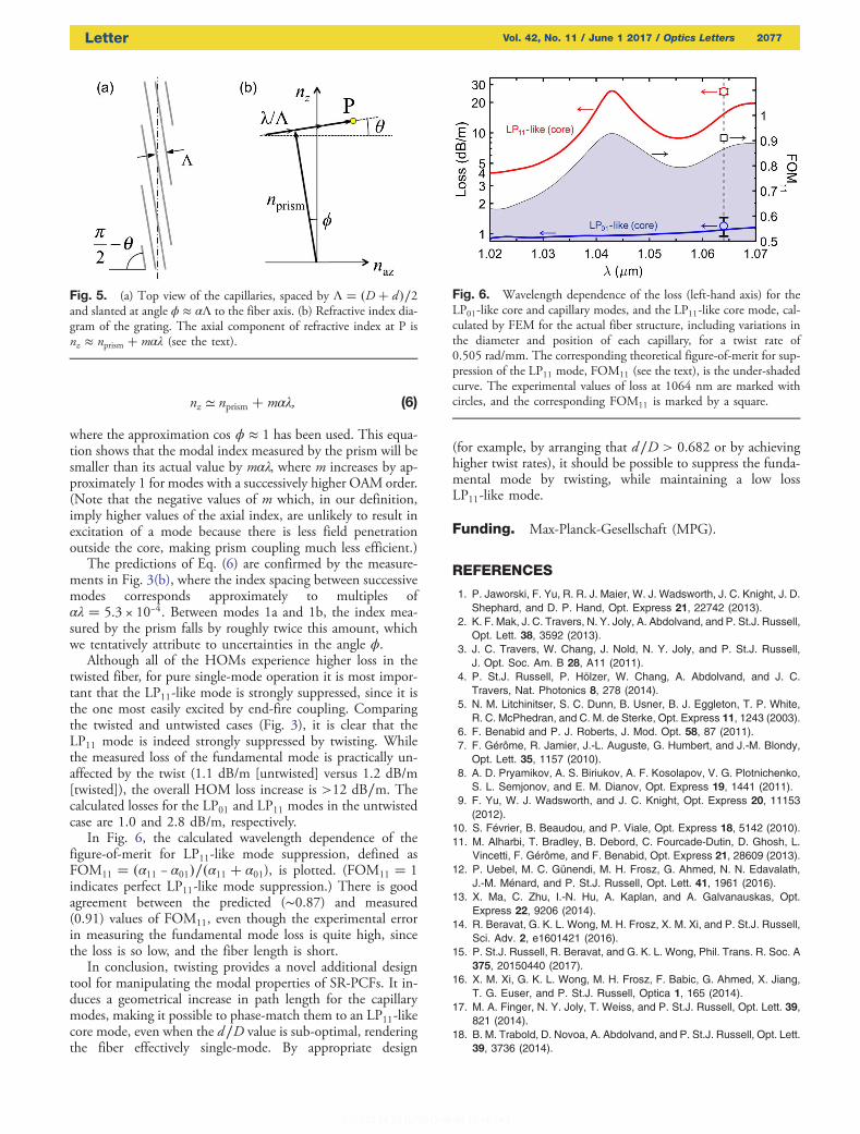
nz ≃ nprism � mαλ; (6)
where the approximation cos ϕ ≈ 1 has been used. This equa-tion shows that the modal index measured by the prism will besmaller than its actual value by mαλ, where m increases by ap-proximately 1 for modes with a successively higher OAM order.(Note that the negative values of m which, in our definition,imply higher values of the axial index, are unlikely to result inexcitation of a mode because there is less field penetrationoutside the core, making prism coupling much less efficient.)
The predictions of Eq. (6) are confirmed by the measure-ments in Fig. 3(b), where the index spacing between successivemodes corresponds approximately to multiples ofαλ � 5.3 × 10⁻⁴. Between modes 1a and 1b, the index mea-sured by the prism falls by roughly twice this amount, whichwe tentatively attribute to uncertainties in the angle ϕ.
Although all of the HOMs experience higher loss in thetwisted fiber, for pure single-mode operation it is most impor-tant that the LP11-like mode is strongly suppressed, since it isthe one most easily excited by end-fire coupling. Comparingthe twisted and untwisted cases (Fig. 3), it is clear that theLP11 mode is indeed strongly suppressed by twisting. Whilethe measured loss of the fundamental mode is practically un-affected by the twist (1.1 dB/m [untwisted] versus 1.2 dB/m[twisted]), the overall HOM loss increase is >12 dB∕m. Thecalculated losses for the LP01 and LP11 modes in the untwistedcase are 1.0 and 2.8 dB/m, respectively.
In Fig. 6, the calculated wavelength dependence of thefigure-of-merit for LP11-like mode suppression, defined asFOM11 � �α11 − α01�∕�α11 � α01), is plotted. (FOM11 � 1indicates perfect LP11-like mode suppression.) There is goodagreement between the predicted (∼0.87) and measured(0.91) values of FOM11, even though the experimental errorin measuring the fundamental mode loss is quite high, sincethe loss is so low, and the fiber length is short.
In conclusion, twisting provides a novel additional designtool for manipulating the modal properties of SR-PCFs. It in-duces a geometrical increase in path length for the capillarymodes, making it possible to phase-match them to an LP11-likecore mode, even when the d∕D value is sub-optimal, renderingthe fiber effectively single-mode. By appropriate design
(for example, by arranging that d∕D > 0.682 or by achievinghigher twist rates), it should be possible to suppress the funda-mental mode by twisting, while maintaining a low lossLP11-like mode.
Funding. Max-Planck-Gesellschaft (MPG).
REFERENCES
1. P. Jaworski, F. Yu, R. R. J. Maier, W. J. Wadsworth, J. C. Knight, J. D.Shephard, and D. P. Hand, Opt. Express 21, 22742 (2013).
2. K. F. Mak, J. C. Travers, N. Y. Joly, A. Abdolvand, and P. St.J. Russell,Opt. Lett. 38, 3592 (2013).
3. J. C. Travers, W. Chang, J. Nold, N. Y. Joly, and P. St.J. Russell,J. Opt. Soc. Am. B 28, A11 (2011).
4. P. St.J. Russell, P. Hölzer, W. Chang, A. Abdolvand, and J. C.Travers, Nat. Photonics 8, 278 (2014).
5. N. M. Litchinitser, S. C. Dunn, B. Usner, B. J. Eggleton, T. P. White,R. C. McPhedran, and C. M. de Sterke, Opt. Express 11, 1243 (2003).
6. F. Benabid and P. J. Roberts, J. Mod. Opt. 58, 87 (2011).7. F. Gérôme, R. Jamier, J.-L. Auguste, G. Humbert, and J.-M. Blondy,
Opt. Lett. 35, 1157 (2010).8. A. D. Pryamikov, A. S. Biriukov, A. F. Kosolapov, V. G. Plotnichenko,
S. L. Semjonov, and E. M. Dianov, Opt. Express 19, 1441 (2011).9. F. Yu, W. J. Wadsworth, and J. C. Knight, Opt. Express 20, 11153
(2012).10. S. Février, B. Beaudou, and P. Viale, Opt. Express 18, 5142 (2010).11. M. Alharbi, T. Bradley, B. Debord, C. Fourcade-Dutin, D. Ghosh, L.
Vincetti, F. Gérôme, and F. Benabid, Opt. Express 21, 28609 (2013).12. P. Uebel, M. C. Günendi, M. H. Frosz, G. Ahmed, N. N. Edavalath,
J.-M. Ménard, and P. St.J. Russell, Opt. Lett. 41, 1961 (2016).13. X. Ma, C. Zhu, I.-N. Hu, A. Kaplan, and A. Galvanauskas, Opt.
Express 22, 9206 (2014).14. R. Beravat, G. K. L. Wong, M. H. Frosz, X. M. Xi, and P. St.J. Russell,
Sci. Adv. 2, e1601421 (2016).15. P. St.J. Russell, R. Beravat, and G. K. L. Wong, Phil. Trans. R. Soc. A
375, 20150440 (2017).16. X. M. Xi, G. K. L. Wong, M. H. Frosz, F. Babic, G. Ahmed, X. Jiang,
T. G. Euser, and P. St.J. Russell, Optica 1, 165 (2014).17. M. A. Finger, N. Y. Joly, T. Weiss, and P. St.J. Russell, Opt. Lett. 39,
821 (2014).18. B. M. Trabold, D. Novoa, A. Abdolvand, and P. St.J. Russell, Opt. Lett.
39, 3736 (2014).
Fig. 5. (a) Top view of the capillaries, spaced by Λ � �D� d�∕2and slanted at angle ϕ ≈ αΛ to the fiber axis. (b) Refractive index dia-gram of the grating. The axial component of refractive index at P isnz ≈ nprism � mαλ (see the text).
Fig. 6. Wavelength dependence of the loss (left-hand axis) for theLP01-like core and capillary modes, and the LP11-like core mode, cal-culated by FEM for the actual fiber structure, including variations inthe diameter and position of each capillary, for a twist rate of0.505 rad/mm. The corresponding theoretical figure-of-merit for sup-pression of the LP11 mode, FOM11 (see the text), is the under-shadedcurve. The experimental values of loss at 1064 nm are marked withcircles, and the corresponding FOM11 is marked by a square.
Letter Vol. 42, No. 11 / June 1 2017 / Optics Letters 2077