high voltage ceramic disc capacitors (low loss type)...
TRANSCRIPT

Design and specifi cations are each subject to change without notice. Ask factory for the current technical specifi cations before purchase and/or use.Should a safety concern arise regarding this product, please be sure to contact us immediately.
High Voltage Ceramic Disc Capacitors (Low loss type)
E
1
C
2
K
3 4 5 6 7 8 9 10 11 12
Product CodeClass
Class 1Class 2
CodeECCECK
SuffixRated VoltageCode
3A3D3F3J
Rated Volt.1 kVDC2 kVDC3 kVDC6 kVDC
CodeGBR
Char.SL/GPB/Y5PR/Y5R
Temp. Char.Lead StyleCode
A
N
StyleKinked LeadBulkKinked LeadTaped
Cap.47 pF
100 pF1000 pF2200 pF4700 pF
Nominal CapacitanceCap. Tol.±0.5 pF±1.0 pF±5 %±10 %
Cap. Tolerance
N 3 A 1 0 2 K B
Ex.470101102222472
CodeDFJK
P
High Voltage Ceramic Disc Capacitors (Low loss type)
Series:KGE/Char. SL/GP, 1 to 6 kVDCSeries:KBP/Char. B/Y5P, 1 to 3 kVDCSeries:KRP/Char. R/Y5R, 1 to 3 kVDC
■ Features● Wide operating temperature range: (–25 to 105 °C or –25 to 125 °C)● Improved Voltage vs.Temperature Rise● Flame-retardant insulated coating● Easy mounting through kinked leads and radial tap ing
■ Recommended Applications● Snubber circuit for switching power supply● Horizontal resonance circuitry for TVs and CRT displays● Inverter type lighting apparatus● Ballast circuit for LCD backlighting inverter (For series KGE)● Other high voltage pulse and DC circuitry
■ Explanation of Part Numbers
■ Specifi cations
Characteristic Series KGE Series KBP, KRP
OperatingTemperature Range –25 to 105 °C –25 to 125 °C
Rated Voltage 1 kVDC to 6 kVDC 1 kVDC to 3 kVDC
DielectricWithstandingVoltage
Rated Voltage 1 to 3 kVDC: 200 % of Rated Voltage for 1 to 5 secondsRated Voltage 6 kVDC: 150 % of Rated Voltage for 1 to 5 seconds
Rated Voltage 1 to 3 kVDC:200 % of Rated Voltage for 1 to 5 seconds
CapacitanceWithin the specifi ed tolerance, when measured at 1 MHz ± 20 %,1 to 5 Vrms, and 20 °C
Within the specifi ed tolerance,when measured at 1 kHz ± 20 %,1 to 5 Vrms, and 20 °C
Q orDissipation Factor(tand)
30 pF or under Q > 400+20 C (C:Cap.pF)over 30 pF Q > 1000 at 1 MHz ± 20 %,1 to 5 Vrms. and 20 °C
Series KBP : tand > 0.025Series KRP : tand > 0.002at 1 kHz ± 20 %,1 to 5 Vrms. and 20 °C
InsulationResistance
10000 M � min.at 500 VDC 1 minute electrifi cation
TemperatureCharacteristics
Temperature Coeffi cient:+350 to –1000 ppm/°C(Temperature Range:20 to 85°C)
Series Temp.Char max.Cap.Change Temp. RangeKBP B/Y5P ±10 % –25 to 85 °CKRP R/Y5R ±15 % –25 to 85 °C
Feb. 2006
[参考資料]

Design and specifi cations are each subject to change without notice. Ask factory for the current technical specifi cations before purchase and/or use.Should a safety concern arise regarding this product, please be sure to contact us immediately.
High Voltage Ceramic Disc Capacitors (Low loss type)
■ Rated Voltage and Capacitance Range
Series NameTemp.Char.
RatedVoltage
Capacitance Range in pF10 100 1000 10000
Typical Applications
Series KGE SL
1 kVDC
Ballast circuit of LCDbacklighting inverter
Snubber circuit of switching power supply
2 kVDC
3 kVDC
6 kVDC
Series KBP B
1 kVDC Snubber circuit of switching power supply
Horizontal resonancecircuit of TV and CRT display
2 kVDC
3 kVDC
Series KRP R
1 kVDC
Snubber circuit of switching power supply
2 kVDC
3 kVDC
470
220
150
150
5600
5600
2700
4700
4700
2200
■ Dimensions “D” (Body Diameter)
Cap.in pF
KGE KBP KRP
1 kV 2 kV 3 kV 6 kV 1 kV 2 kV 3 kV 1 kV 2 kV 3 kV
12 to 22 6.0 7.0 7.0 7.022 to 33 6.0 7.0 7.0 8.0
39 6.0 7.0 7.0 9.047 6.0 7.0 7.0 9.056 6.0 7.0 8.0 10.068 6.0 7.0 8.0 11.082 6.0 7.0 9.0 11.0
100 7.0 8.0 10.0 13.0 6.0 7.0 7.5 6.0 7.0 7.5120 7.0 8.0 10.0 13.0 6.0 7.0 7.5 6.0 7.0 7.5150 8.0 9.0 11.0 15.0 6.0 7.0 7.5 6.0 7.0 7.5180 8.0 10.0 6.0 7.0 7.5 6.0 7.0 7.5220 9.0 10.0 6.0 7.0 7.5 6.0 7.0 8.0270 9.0 6.0 7.0 7.5 6.0 7.0 8.0330 11.0 6.0 7.0 8.0 6.0 7.5 8.5390 11.0 6.0 7.0 9.0 7.0 7.5 9.5470 13.0 6.0 7.5 9.5 7.0 9.0 9.5560 7.0 8.0 10.0 7.0 9.0 10.5680 7.0 9.0 11.0 7.5 10.0 10.5820 7.5 9.0 11.0 7.5 10.0 12.5
1000 9.0 10.0 12.5 9.0 12.0 12.51200 9.0 10.5 14.5 9.0 12.0 14.51500 9.5 12.0 14.5 10.5 12.0 14.51800 12.0 12.5 16.0 10.5 14.0 16.52200 12.0 14.0 17.0 11.5 16.0 17.02700 13.5 16.0 18.5 13.0 16.03300 13.5 17.0 13.0 19.03900 15.5 18.0 14.0 20.04700 15.5 25.0 16.5 21.05600 17.0 25.0
unit : mm
Feb. 2006
[参考資料]
Design and specifi cations are each subject to change without notice. Ask factory for the current technical specifi cations before purchase and/or use.Should a safety concern arise regarding this product, please be sure to contact us immediately.
High Voltage Ceramic Disc Capacitors (Low loss type)
D T
4.0
max
.
F
d±0.05
20.0
min
.
D
fd fD0
W2
t2
t1
H0
L
WW0 W
1
∆h1 ∆h2
T
e
P
P0
P2
P1 F fd
PD
P1
P2
P0
F
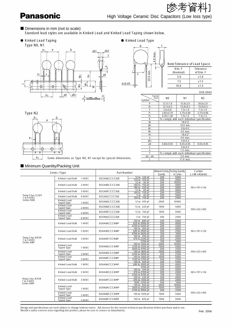
■ Dimensions in mm (not to scale) Standard lead styles are available in Kinked Lead and Kinked Lead Taping shown below.
● Kinked Lead Type
Note:Tolerance of Lead Space
Dim. F(Nominal)
Toleranceof Dim. F
5.0 ±1.0
7.5 ±1.5
10.0 ±1.5
● Kinked Lead Taping Type N0, N1
Type N2
Same dimensions as Type N0, N1 except for special dimensions.
TapingType
SymbolN0 N1 N2
P 12.7±1.0 15.0±2.0 30.0±2.0P0 12.7±0.3 15.0±0.3 15.0±0.3F 5.0±0.8 7.5±1.0 7.5±1.0P1 3.85±0.70 3.75±0.80 3.75±0.80P2 6.35±1.30 7.5±1.5 7.5±1.5D To comply with each individual spec i fi ca tionW 18.0+1.0
W0 10.0 min.W1 9.0±0.5W2 3.0 max.H0 18.0+2.0
e 4.0 max.fD0 4.0±0.2fd 0.60±0.05 0.65±0.05 0.65±0.05t1 0.6±0.3t2 1.5 max.T To comply with each individual specifi cation
∆h1, ∆h2 2.0 max.L 11.0 max.
–0
–0.5
Series / Type Part Number Minimum Packing Quantity
Packing Quantity in Carton
CartonL�W�H(mm)
Temp.Char. SL/GP1 to 6 kVDCSeries KGE
Kinked Lead Bulk 1 kVDC ECCA3A����GE 12 to 120 pF 200 5000
365�197�126
150 to 470 pF 200 4000
Kinked Lead Bulk 2 kVDC ECCA3D����GE12 to 82 pF 200 10000
100 to 150 pF 200 4000180 to 220 pF 200 3000
Kinked Lead Bulk 3 kVDC ECCA3F����GE 12 to 82 pF 200 4000100 to 150 pF 200 2000
Kinked Lead Bulk 6 kVDC ECCA3J����GE 5 to 82 pF 200 3000100 to 150 pF 200 2000
Kinked LeadTaped Type 1 kVDC ECCN3A����GE 12 to 470 pF 2000 10000
358�232�305
Kinked LeadTaped Type 2 kVDC ECCN3D����GE 12 to 220 pF 1000 5000
Kinked LeadTaped Type 3 kVDC ECCN3F����GE 12 to 150 pF 1000 5000
Kinked LeadTaped Type 6 kVDC ECCN3J����GE 5 to 150 pF 500 2500
Temp.Char. B/Y5P1 to 3 kVDCSeries KBP
Kinked Lead Bulk 1 kVDC ECKA3A���KBP100 to 680 pF 200 5000
365�197�126
820 to 3900 pF 200 40004700 to 5600 pF 200 2000
Kinked Lead Bulk 2 kVDC ECKA3D���KBP100 to 560 pF 200 4000680 to 3900 pF 200 2000
4700 to 5600 pF 100 1000
Kinked Lead Bulk 3 kVDC ECKA3F���KBP100 to 390 pF 200 4000470 to 2200 pF 200 2000
2700 pF 100 1000
Kinked LeadTaped Type 1 kVDC ECKN3A���KBP
100 to 1000 pF 2000 10000
358�232�305
1200 to 3300 pF 1000 50003900 to 4700 pF 500 2500
Kinked LeadTaped Type 2 kVDC ECKN3D���KBP 100 to 1800 pF 1000 5000
2200 to 3900 pF 500 2500Kinked LeadTaped Type 3 kVDC ECKN3F���KBP 100 to 1000 pF 1000 5000
1200 to 2700 pF 500 2500
Temp.Char. R/Y5R1 to 3 kVDCSeries KRP
Kinked Lead Bulk 1 kVDC ECKA3A���KRP100 to 560 pF 200 5000
365�197�126
680 to 3900 pF 200 40004700 pF 200 2000
Kinked Lead Bulk 2 kVDC ECKA3D���KRP100 to 390 pF 200 4000470 to 2700 pF 200 2000
3300 to 4700 pF 100 1000
Kinked Lead Bulk 3 kVDC ECKA3F���KRP100 to 330 pF 200 4000390 to 1500 pF 200 20001800, 2200 pF 200 1000
Kinked LeadTaped Type 1 kVDC ECKN3A���KRP
100 to 820 pF 2000 10000
358�232�305
1000 to 2200 pF 1000 50002700 to 3900 pF 500 2500
Kinked LeadTaped Type 2 kVDC ECKN3D���KRP 100 to 1500 pF 1000 5000
Kinked LeadTaped Type 3 kVDC ECKN3F���KRP 100 to 820 pF 1000 5000
■ Minimum Quantity/Packing Unit
Unit (mm)
Feb. 2006
[参考資料]
Design and specifi cations are each subject to change without notice. Ask factory for the current technical specifi cations before purchase and/or use.Should a safety concern arise regarding this product, please be sure to contact us immediately.
High Voltage Ceramic Disc Capacitors (Low loss type)
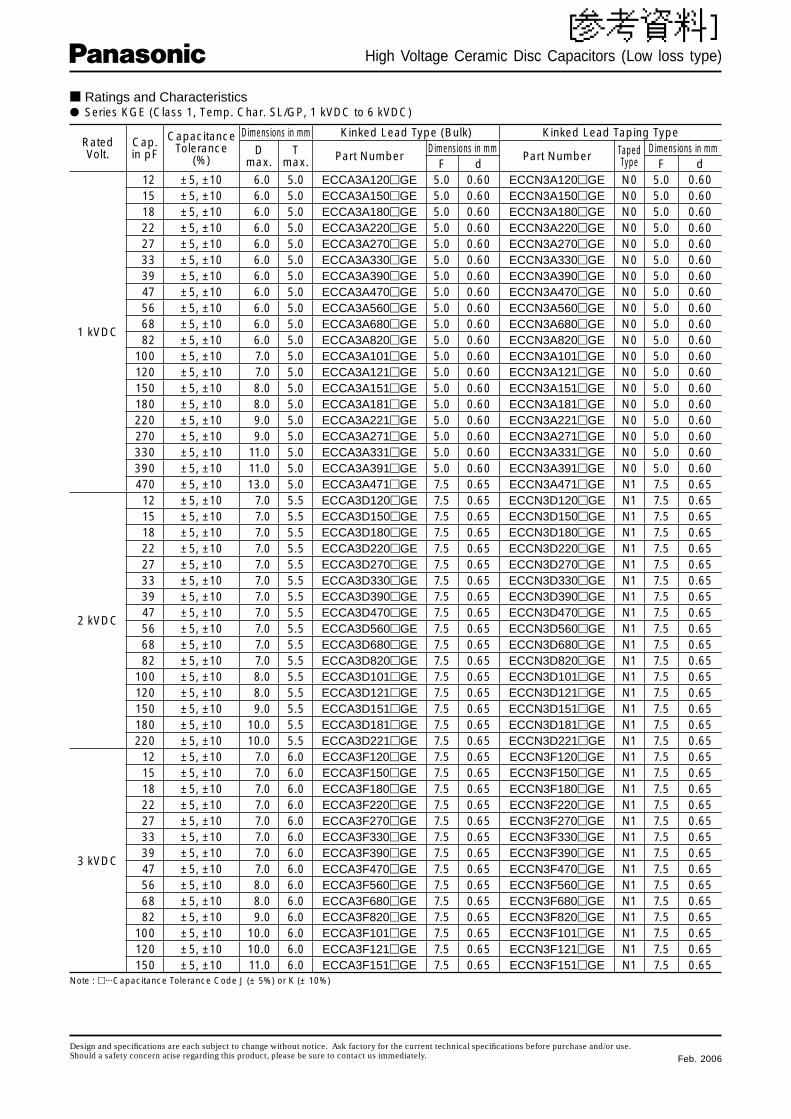
■ Ratings and Characteristics● Series KGE (Class 1, Temp. Char. SL/GP, 1 kVDC to 6 kVDC)
RatedVolt.
Cap.in pF
CapacitanceTolerance
(%)
Dimensions in mm Kinked Lead Type (Bulk) Kinked Lead Taping TypeD
max.T
max. Part NumberDimensions in mm
Part Number TapedType
Dimensions in mmF d F d
1 kVDC
12 ±5, ±10 6.0 5.0 ECCA3A120�GE 5.0 0.60 ECCN3A120�GE N0 5.0 0.6015 ±5, ±10 6.0 5.0 ECCA3A150�GE 5.0 0.60 ECCN3A150�GE N0 5.0 0.6018 ±5, ±10 6.0 5.0 ECCA3A180�GE 5.0 0.60 ECCN3A180�GE N0 5.0 0.6022 ±5, ±10 6.0 5.0 ECCA3A220�GE 5.0 0.60 ECCN3A220�GE N0 5.0 0.6027 ±5, ±10 6.0 5.0 ECCA3A270�GE 5.0 0.60 ECCN3A270�GE N0 5.0 0.6033 ±5, ±10 6.0 5.0 ECCA3A330�GE 5.0 0.60 ECCN3A330�GE N0 5.0 0.6039 ±5, ±10 6.0 5.0 ECCA3A390�GE 5.0 0.60 ECCN3A390�GE N0 5.0 0.6047 ±5, ±10 6.0 5.0 ECCA3A470�GE 5.0 0.60 ECCN3A470�GE N0 5.0 0.6056 ±5, ±10 6.0 5.0 ECCA3A560�GE 5.0 0.60 ECCN3A560�GE N0 5.0 0.6068 ±5, ±10 6.0 5.0 ECCA3A680�GE 5.0 0.60 ECCN3A680�GE N0 5.0 0.6082 ±5, ±10 6.0 5.0 ECCA3A820�GE 5.0 0.60 ECCN3A820�GE N0 5.0 0.60
100 ±5, ±10 7.0 5.0 ECCA3A101�GE 5.0 0.60 ECCN3A101�GE N0 5.0 0.60120 ±5, ±10 7.0 5.0 ECCA3A121�GE 5.0 0.60 ECCN3A121�GE N0 5.0 0.60150 ±5, ±10 8.0 5.0 ECCA3A151�GE 5.0 0.60 ECCN3A151�GE N0 5.0 0.60180 ±5, ±10 8.0 5.0 ECCA3A181�GE 5.0 0.60 ECCN3A181�GE N0 5.0 0.60220 ±5, ±10 9.0 5.0 ECCA3A221�GE 5.0 0.60 ECCN3A221�GE N0 5.0 0.60270 ±5, ±10 9.0 5.0 ECCA3A271�GE 5.0 0.60 ECCN3A271�GE N0 5.0 0.60330 ±5, ±10 11.0 5.0 ECCA3A331�GE 5.0 0.60 ECCN3A331�GE N0 5.0 0.60390 ±5, ±10 11.0 5.0 ECCA3A391�GE 5.0 0.60 ECCN3A391�GE N0 5.0 0.60470 ±5, ±10 13.0 5.0 ECCA3A471�GE 7.5 0.65 ECCN3A471�GE N1 7.5 0.65
2 kVDC
12 ±5, ±10 7.0 5.5 ECCA3D120�GE 7.5 0.65 ECCN3D120�GE N1 7.5 0.6515 ±5, ±10 7.0 5.5 ECCA3D150�GE 7.5 0.65 ECCN3D150�GE N1 7.5 0.6518 ±5, ±10 7.0 5.5 ECCA3D180�GE 7.5 0.65 ECCN3D180�GE N1 7.5 0.6522 ±5, ±10 7.0 5.5 ECCA3D220�GE 7.5 0.65 ECCN3D220�GE N1 7.5 0.6527 ±5, ±10 7.0 5.5 ECCA3D270�GE 7.5 0.65 ECCN3D270�GE N1 7.5 0.6533 ±5, ±10 7.0 5.5 ECCA3D330�GE 7.5 0.65 ECCN3D330�GE N1 7.5 0.6539 ±5, ±10 7.0 5.5 ECCA3D390�GE 7.5 0.65 ECCN3D390�GE N1 7.5 0.6547 ±5, ±10 7.0 5.5 ECCA3D470�GE 7.5 0.65 ECCN3D470�GE N1 7.5 0.6556 ±5, ±10 7.0 5.5 ECCA3D560�GE 7.5 0.65 ECCN3D560�GE N1 7.5 0.6568 ±5, ±10 7.0 5.5 ECCA3D680�GE 7.5 0.65 ECCN3D680�GE N1 7.5 0.6582 ±5, ±10 7.0 5.5 ECCA3D820�GE 7.5 0.65 ECCN3D820�GE N1 7.5 0.65
100 ±5, ±10 8.0 5.5 ECCA3D101�GE 7.5 0.65 ECCN3D101�GE N1 7.5 0.65120 ±5, ±10 8.0 5.5 ECCA3D121�GE 7.5 0.65 ECCN3D121�GE N1 7.5 0.65150 ±5, ±10 9.0 5.5 ECCA3D151�GE 7.5 0.65 ECCN3D151�GE N1 7.5 0.65180 ±5, ±10 10.0 5.5 ECCA3D181�GE 7.5 0.65 ECCN3D181�GE N1 7.5 0.65220 ±5, ±10 10.0 5.5 ECCA3D221�GE 7.5 0.65 ECCN3D221�GE N1 7.5 0.65
3 kVDC
12 ±5, ±10 7.0 6.0 ECCA3F120�GE 7.5 0.65 ECCN3F120�GE N1 7.5 0.6515 ±5, ±10 7.0 6.0 ECCA3F150�GE 7.5 0.65 ECCN3F150�GE N1 7.5 0.6518 ±5, ±10 7.0 6.0 ECCA3F180�GE 7.5 0.65 ECCN3F180�GE N1 7.5 0.6522 ±5, ±10 7.0 6.0 ECCA3F220�GE 7.5 0.65 ECCN3F220�GE N1 7.5 0.6527 ±5, ±10 7.0 6.0 ECCA3F270�GE 7.5 0.65 ECCN3F270�GE N1 7.5 0.6533 ±5, ±10 7.0 6.0 ECCA3F330�GE 7.5 0.65 ECCN3F330�GE N1 7.5 0.6539 ±5, ±10 7.0 6.0 ECCA3F390�GE 7.5 0.65 ECCN3F390�GE N1 7.5 0.6547 ±5, ±10 7.0 6.0 ECCA3F470�GE 7.5 0.65 ECCN3F470�GE N1 7.5 0.6556 ±5, ±10 8.0 6.0 ECCA3F560�GE 7.5 0.65 ECCN3F560�GE N1 7.5 0.6568 ±5, ±10 8.0 6.0 ECCA3F680�GE 7.5 0.65 ECCN3F680�GE N1 7.5 0.6582 ±5, ±10 9.0 6.0 ECCA3F820�GE 7.5 0.65 ECCN3F820�GE N1 7.5 0.65
100 ±5, ±10 10.0 6.0 ECCA3F101�GE 7.5 0.65 ECCN3F101�GE N1 7.5 0.65120 ±5, ±10 10.0 6.0 ECCA3F121�GE 7.5 0.65 ECCN3F121�GE N1 7.5 0.65150 ±5, ±10 11.0 6.0 ECCA3F151�GE 7.5 0.65 ECCN3F151�GE N1 7.5 0.65
Note : �···Capacitance Tolerance Code J (± 5%) or K (± 10%)
Feb. 2006
[参考資料]

Design and specifi cations are each subject to change without notice. Ask factory for the current technical specifi cations before purchase and/or use.Should a safety concern arise regarding this product, please be sure to contact us immediately.
High Voltage Ceramic Disc Capacitors (Low loss type)
■ Ratings and Characteristics● Series KGE (Class 1, Temp. Char. SL/GP, 1 to 6 kVDC) (Continuation)
RatedVolt.
Cap.in pF
CapacitanceTolerance
(%)
Dimensions in mm Kinked Lead Type (Bulk) Kinked Lead Taping TypeD
max.T
max. Part NumberDimensions in mm
Part Number TapedType
Dimensions in mmF d F d
6 kVDC
5 ±0.5pF or ±1pF 7.0 6.0 ECCA3J050�GE 7.5 0.65 ECCN3J050�GE N1 7.5 0.656 ±0.5pF or ±1pF 7.0 6.0 ECCA3J060�GE 7.5 0.65 ECCN3J060�GE N1 7.5 0.657 ±0.5pF or ±1pF 7.0 6.0 ECCA3J070�GE 7.5 0.65 ECCN3J070�GE N1 7.5 0.658 ±0.5pF or ±1pF 7.0 6.0 ECCA3J080�GE 7.5 0.65 ECCN3J080�GE N1 7.5 0.659 ±0.5pF or ±1pF 7.0 6.0 ECCA3J090�GE 7.5 0.65 ECCN3J090�GE N1 7.5 0.65
10 ±0.5pF or ±1pF 7.0 6.0 ECCA3J100�GE 7.5 0.65 ECCN3J100�GE N1 7.5 0.6512 ±5 or ±10 7.0 6.0 ECCA3J120�GE 7.5 0.65 ECCN3J120�GE N1 7.5 0.6515 ±5 or ±10 7.0 6.0 ECCA3J150�GE 7.5 0.65 ECCN3J150�GE N1 7.5 0.6518 ±5 or ±10 7.0 6.0 ECCA3J180�GE 7.5 0.65 ECCN3J180�GE N1 7.5 0.6522 ±5 or ±10 7.0 6.0 ECCA3J220�GE 7.5 0.65 ECCN3J220�GE N1 7.5 0.6527 ±5 or ±10 8.0 6.0 ECCA3J270�GE 7.5 0.65 ECCN3J270�GE N1 7.5 0.6533 ±5 or ±10 8.0 6.0 ECCA3J330�GE 7.5 0.65 ECCN3J330�GE N1 7.5 0.6539 ±5 or ±10 9.0 6.0 ECCA3J390�GE 7.5 0.65 ECCN3J390�GE N1 7.5 0.6547 ±5 or ±10 9.0 6.0 ECCA3J470�GE 7.5 0.65 ECCN3J470�GE N1 7.5 0.6556 ±5 or ±10 10.0 6.0 ECCA3J560�GE 7.5 0.65 ECCN3J560�GE N1 7.5 0.6568 ±5 or ±10 11.0 6.0 ECCA3J680�GE 7.5 0.65 ECCN3J680�GE N1 7.5 0.6582 ±5 or ±10 11.0 6.0 ECCA3J820�GE 7.5 0.65 ECCN3J820�GE N1 7.5 0.65
100 ±5 or ±10 13.0 6.0 ECCA3J101�GE 7.5 0.65 ECCN3J101�GE N1 7.5 0.65120 ±5 or ±10 13.0 6.0 ECCA3J121�GE 7.5 0.65 ECCN3J121�GE N1 7.5 0.65150 ±5 or ±10 15.0 6.0 ECCA3J151�GE 7.5 0.65 ECCN3J151�GE N2 7.5 0.65
Note : �···Capacitance Tolerance Code D (± 0.5pF) or F (± 1pF) or J (± 5%) or K (± 10%)
RatedVolt.
Cap.in pF
CapacitanceTolerance
(%)
Dimensions in mm Kinked Lead Type (Bulk) Kinked Lead Taping TypeD
max.T
max. Part NumberDimensions in mm
Part Number TapedType
Dimensions in mmF d F d
1 kVDC
100 ±10 6.0 4.5 ECKA3A101KBP 5.0 0.60 ECKN3A101KBP N0 5.0 0.60120 ±10 6.0 4.5 ECKA3A121KBP 5.0 0.60 ECKN3A121KBP N0 5.0 0.60150 ±10 6.0 4.5 ECKA3A151KBP 5.0 0.60 ECKN3A151KBP N0 5.0 0.60180 ±10 6.0 4.5 ECKA3A181KBP 5.0 0.60 ECKN3A181KBP N0 5.0 0.60220 ±10 6.0 4.5 ECKA3A221KBP 5.0 0.60 ECKN3A221KBP N0 5.0 0.60270 ±10 6.0 4.5 ECKA3A271KBP 5.0 0.60 ECKN3A271KBP N0 5.0 0.60330 ±10 6.0 4.5 ECKA3A331KBP 5.0 0.60 ECKN3A331KBP N0 5.0 0.60390 ±10 6.0 4.5 ECKA3A391KBP 5.0 0.60 ECKN3A391KBP N0 5.0 0.60470 ±10 6.0 4.5 ECKA3A471KBP 5.0 0.60 ECKN3A471KBP N0 5.0 0.60560 ±10 7.0 4.5 ECKA3A561KBP 5.0 0.60 ECKN3A561KBP N0 5.0 0.60680 ±10 7.0 4.5 ECKA3A681KBP 5.0 0.60 ECKN3A681KBP N0 5.0 0.60820 ±10 7.5 4.5 ECKA3A821KBP 5.0 0.60 ECKN3A821KBP N0 5.0 0.60
1000 ±10 9.0 4.5 ECKA3A102KBP 5.0 0.60 ECKN3A102KBP N0 5.0 0.601200 ±10 9.0 4.5 ECKA3A122KBP 5.0 0.60 ECKN3A122KBP N0 5.0 0.601500 ±10 9.5 4.5 ECKA3A152KBP 5.0 0.60 ECKN3A152KBP N0 5.0 0.601800 ±10 10.0 4.5 ECKA3A182KBP 5.0 0.60 ECKN3A182KBP N0 5.0 0.602200 ±10 12.0 4.5 ECKA3A222KBP 5.0 0.60 ECKN3A222KBP N0 5.0 0.602700 ±10 12.0 4.5 ECKA3A272KBP 5.0 0.60 ECKN3A272KBP N0 5.0 0.603300 ±10 13.5 4.5 ECKA3A332KBP 10.0 0.65 ECKN3A332KBP N1 7.5 0.653900 ±10 13.5 4.5 ECKA3A392KBP 10.0 0.65 ECKN3A392KBP N1 7.5 0.654700 ±10 15.5 4.5 ECKA3A472KBP 10.0 0.65 ECKN3A472KBP N2 7.5 0.655600 ±10 17.0 4.5 ECKA3A562KBP 10.0 0.65 ECKN3A562KBP N2 7.5 0.65
● Series KBP (Class 2, Temp. Char. B/Y5P, 1 to 3 kVDC)
Feb. 2006
[参考資料]

Design and specifi cations are each subject to change without notice. Ask factory for the current technical specifi cations before purchase and/or use.Should a safety concern arise regarding this product, please be sure to contact us immediately.
High Voltage Ceramic Disc Capacitors (Low loss type)
RatedVolt.
Cap.in pF
CapacitanceTolerance
(%)
Dimensions in mm Kinked Lead Type (Bulk) Kinked Lead Taping TypeD
max.T
max. Part NumberDimensions in mm
Part Number TapedType
Dimensions in mmF d F d
2 kVDC
100 ±10 7.0 5.0 ECKA3D101KBP 7.5 0.65 ECKN3D101KBP N1 7.5 0.65120 ±10 7.0 5.0 ECKA3D121KBP 7.5 0.65 ECKN3D121KBP N1 7.5 0.65150 ±10 7.0 5.0 ECKA3D151KBP 7.5 0.65 ECKN3D151KBP N1 7.5 0.65180 ±10 7.0 5.0 ECKA3D181KBP 7.5 0.65 ECKN3D181KBP N1 7.5 0.65220 ±10 7.0 5.0 ECKA3D221KBP 7.5 0.65 ECKN3D221KBP N1 7.5 0.65270 ±10 7.0 5.0 ECKA3D271KBP 7.5 0.65 ECKN3D271KBP N1 7.5 0.65330 ±10 7.0 5.0 ECKA3D331KBP 7.5 0.65 ECKN3D331KBP N1 7.5 0.65390 ±10 7.0 5.0 ECKA3D391KBP 7.5 0.65 ECKN3D391KBP N1 7.5 0.65470 ±10 7.5 5.0 ECKA3D471KBP 7.5 0.65 ECKN3D471KBP N1 7.5 0.65560 ±10 8.0 5.0 ECKA3D561KBP 7.5 0.65 ECKN3D561KBP N1 7.5 0.65680 ±10 9.0 5.0 ECKA3D681KBP 7.5 0.65 ECKN3D681KBP N1 7.5 0.65820 ±10 9.0 5.0 ECKA3D821KBP 7.5 0.65 ECKN3D821KBP N1 7.5 0.65
1000 ±10 10.0 5.0 ECKA3D102KBP 7.5 0.65 ECKN3D102KBP N1 7.5 0.651200 ±10 10.5 5.0 ECKA3D122KBP 7.5 0.65 ECKN3D122KBP N1 7.5 0.651500 ±10 12.0 5.0 ECKA3D152KBP 7.5 0.65 ECKN3D152KBP N1 7.5 0.651800 ±10 12.5 5.0 ECKA3D182KBP 7.5 0.65 ECKN3D182KBP N1 7.5 0.652200 ±10 14.0 5.0 ECKA3D222KBP 10.0 0.65 ECKN3D222KBP N2 7.5 0.652700 ±10 16.0 5.0 ECKA3D272KBP 10.0 0.65 ECKN3D272KBP N2 7.5 0.653300 ±10 17.0 5.0 ECKA3D332KBP 10.0 0.65 ECKN3D332KBP N2 7.5 0.653900 ±10 18.0 5.0 ECKA3D392KBP 10.0 0.65 ECKN3D392KBP N2 7.5 0.654700 ±10 25.0 5.0 ECKA3D472KBP 10.0 0.65 —— — — —5600 ±10 25.0 5.0 ECKA3D562KBP 10.0 0.65 —— — — —
3 kVDC
100 ±10 7.5 6.0 ECKA3F101KBP 7.5 0.65 ECKN3F101KBP N1 7.5 0.65120 ±10 7.5 6.0 ECKA3F121KBP 7.5 0.65 ECKN3F121KBP N1 7.5 0.65150 ±10 7.5 6.0 ECKA3F151KBP 7.5 0.65 ECKN3F151KBP N1 7.5 0.65180 ±10 7.5 6.0 ECKA3F181KBP 7.5 0.65 ECKN3F181KBP N1 7.5 0.65220 ±10 7.5 6.0 ECKA3F221KBP 7.5 0.65 ECKN3F221KBP N1 7.5 0.65270 ±10 7.5 6.0 ECKA3F271KBP 7.5 0.65 ECKN3F271KBP N1 7.5 0.65330 ±10 8.0 6.0 ECKA3F331KBP 7.5 0.65 ECKN3F331KBP N1 7.5 0.65390 ±10 9.0 6.0 ECKA3F391KBP 7.5 0.65 ECKN3F391KBP N1 7.5 0.65470 ±10 9.5 6.0 ECKA3F471KBP 7.5 0.65 ECKN3F471KBP N1 7.5 0.65560 ±10 10.0 6.0 ECKA3F561KBP 7.5 0.65 ECKN3F561KBF N1 7.5 0.65680 ±10 11.0 6.0 ECKA3F681KBP 7.5 0.65 ECKN3F681KBP N1 7.5 0.65820 ±10 11.0 6.0 ECKA3F821KBP 7.5 0.65 ECKN3F821KBP N1 7.5 0.65
1000 ±10 12.5 6.0 ECKA3F102KBP 7.5 0.65 ECKN3F102KBP N1 7.5 0.651200 ±10 14.5 6.0 ECKA3F122KBP 10.0 0.65 ECKN3F122KBP N1 7.5 0.651500 ±10 14.5 6.0 ECKA3F152KBP 10.0 0.65 ECKN3F152KBP N1 7.5 0.651800 ±10 16.0 6.0 ECKA3F182KBP 10.0 0.65 ECKN3F182KBP N2 7.5 0.652200 ±10 17.0 6.0 ECKA3F222KBP 10.0 0.65 ECKN3F222KBP N2 7.5 0.652700 ±10 18.5 6.0 ECKA3F272KBP 10.0 0.65 ECKN3F272KBP N2 7.5 0.65
■ Ratings and Characteristics● Series KBP (Class 2, Temp. Char. B/Y5P, 1 to 3 kVDC) (Continuation)
Feb. 2006
[参考資料]

Design and specifi cations are each subject to change without notice. Ask factory for the current technical specifi cations before purchase and/or use.Should a safety concern arise regarding this product, please be sure to contact us immediately.
High Voltage Ceramic Disc Capacitors (Low loss type)
RatedVolt.
Cap.in pF
CapacitanceTolerance
(%)
Dimensions in mm Kinked Lead Type (Bulk) Kinked Lead Taping TypeD
max.T
max. Part NumberDimensions in mm
Part Number TapedType
Dimensions in mmF d F d
1 kVDC
100 ±10 6.0 4.5 ECKA3A101KRP 5.0 0.60 ECKN3A101KRP N0 5.0 0.60120 ±10 6.0 4.5 ECKA3A121KRP 5.0 0.60 ECKN3A121KRP N0 5.0 0.60150 ±10 6.0 4.5 ECKA3A151KRP 5.0 0.60 ECKN3A151KRP N0 5.0 0.60180 ±10 6.0 4.5 ECKA3A181KRP 5.0 0.60 ECKN3A181KRP N0 5.0 0.60220 ±10 6.0 4.5 ECKA3A221KRP 5.0 0.60 ECKN3A221KRP N0 5.0 0.60270 ±10 6.0 4.5 ECKA3A271KRP 5.0 0.60 ECKN3A271KRP N0 5.0 0.60330 ±10 6.0 4.5 ECKA3A331KRP 5.0 0.60 ECKN3A331KRP N0 5.0 0.60390 ±10 7.0 4.5 ECKA3A391KRP 5.0 0.60 ECKN3A391KRP N0 5.0 0.60470 ±10 7.0 4.5 ECKA3A471KRP 5.0 0.60 ECKN3A471KRP N0 5.0 0.60560 ±10 7.0 4.5 ECKA3A561KRP 5.0 0.60 ECKN3A561KRP N0 5.0 0.60680 ±10 7.5 4.5 ECKA3A681KRP 5.0 0.60 ECKN3A681KRP N0 5.0 0.60820 ±10 7.5 4.5 ECKA3A821KRP 5.0 0.60 ECKN3A821KRP N0 5.0 0.60
1000 ±10 9.0 4.5 ECKA3A102KRP 5.0 0.60 ECKN3A102KRP N0 5.0 0.601200 ±10 9.0 4.5 ECKA3A122KRP 5.0 0.60 ECKN3A122KRP N0 5.0 0.601500 ±10 10.5 4.5 ECKA3A152KRP 5.0 0.60 ECKN3A152KRP N0 5.0 0.601800 ±10 10.5 4.5 ECKA3A182KRP 5.0 0.60 ECKN3A182KRP N0 5.0 0.602200 ±10 11.5 4.5 ECKA3A222KRP 5.0 0.60 ECKN3A222KRP N0 5.0 0.602700 ±10 13.0 4.5 ECKA3A272KRP 7.5 0.65 ECKN3A272KRP N1 7.5 0.653300 ±10 13.0 4.5 ECKA3A332KRP 7.5 0.65 ECKN3A332KRP N1 7.5 0.653900 ±10 14.0 4.5 ECKA3A392KRP 7.5 0.65 ECKN3A392KRP N1 7.5 0.654700 ±10 16.5 4.5 ECKA3A472KRP 7.5 0.65 —— — — —
2 kVDC
100 ±10 7.0 5.0 ECKA3D101KRP 7.5 0.65 ECKN3D101KRP N1 7.5 0.65120 ±10 7.0 5.0 ECKA3D121KRP 7.5 0.65 ECKN3D121KRP N1 7.5 0.65150 ±10 7.0 5.0 ECKA3D151KRP 7.5 0.65 ECKN3D151KRP N1 7.5 0.65180 ±10 7.0 5.0 ECKA3D181KRP 7.5 0.65 ECKN3D181KRP N1 7.5 0.65220 ±10 7.0 5.0 ECKA3D221KRP 7.5 0.65 ECKN3D221KRP N1 7.5 0.65270 ±10 7.0 5.0 ECKA3D271KRP 7.5 0.65 ECKN3D271KRP N1 7.5 0.65330 ±10 7.5 5.0 ECKA3D331KRP 7.5 0.65 ECKN3D331KRP N1 7.5 0.65390 ±10 7.5 5.0 ECKA3D391KRP 7.5 0.65 ECKN3D391KRP N1 7.5 0.65470 ±10 9.0 5.0 ECKA3D471KRP 7.5 0.65 ECKN3D471KRP N1 7.5 0.65560 ±10 9.0 5.0 ECKA3D561KRP 7.5 0.65 ECKN3D561KRP N1 7.5 0.65680 ±10 10.0 5.0 ECKA3D681KRP 7.5 0.65 ECKN3D681KRP N1 7.5 0.65820 ±10 10.0 5.0 ECKA3D821KRP 7.5 0.65 ECKN3D821KRP N1 7.5 0.65
1000 ±10 12.0 5.0 ECKA3D102KRP 7.5 0.65 ECKN3D102KRP N1 7.5 0.651200 ±10 12.0 5.0 ECKA3D122KRP 7.5 0.65 ECKN3D122KRP N1 7.5 0.651500 ±10 12.0 5.0 ECKA3D152KRP 7.5 0.65 ECKN3D152KRP N1 7.5 0.651800 ±10 14.0 5.0 ECKA3D182KRP 10.0 0.65 —— — — —2200 ±10 16.0 5.0 ECKA3D222KRP 10.0 0.65 —— — — —2700 ±10 16.0 5.0 ECKA3D272KRP 10.0 0.65 —— — — —3300 ±10 19.0 5.0 ECKA3D332KRP 10.0 0.65 —— — — —3900 ±10 20.0 5.0 ECKA3D392KRP 10.0 0.65 —— — — —4700 ±10 21.0 5.0 ECKA3D472KRP 10.0 0.65 —— — — —
■ Ratings and Characteristics● Series KRP (Class 2, Temp. Char. R/Y5R, 1 to 3 kVDC)
Feb. 2006
[参考資料]

Design and specifi cations are each subject to change without notice. Ask factory for the current technical specifi cations before purchase and/or use.Should a safety concern arise regarding this product, please be sure to contact us immediately.
High Voltage Ceramic Disc Capacitors (Low loss type)
–15–10
–50
+5+10
–20 0 20 40 60 80 100 120
Series KGE (Char. SL/GP)(Temp. Coeff. : +350 to –1000 ppm/˚C)
Cap
acita
nce
Cha
nge
(%)
Temperature (°C)
–30–20–10
0+10+20
–20 0 20 40 60 80 100 120
( )Series KBP (Char. B/Y5P)
Temp. Range : –25 to 85 °Cmax. Cap. Change : ±10 %
Cap
acita
nce
Cha
nge
(%)
Temperature (°C)
–30–20–10
0+10+20
–20 0 20 40 60 80 100 120
Series KRP (Char. R/Y5R)
Cap
acita
nce
Cha
nge
(%)
Temperature (°C)
( )Temp. Range : –25 to 85 °Cmax. Cap. Change : ±15 %
RatedVolt.
Cap.in pF
CapacitanceTolerance
(%)
Dimensions in mm Kinked Lead Type (Bulk) Kinked Lead Taping TypeD
max.T
max. Part NumberDimensions in mm
Part Number TapedType
Dimensions in mmF d F d
3 kVDC
100 ±10 7.5 5.5 ECKA3F101KRP 7.5 0.65 ECKN3F101KRP N1 7.5 0.65120 ±10 7.5 5.5 ECKA3F121KRP 7.5 0.65 ECKN3F121KRP N1 7.5 0.65150 ±10 7.5 5.5 ECKA3F151KRP 7.5 0.65 ECKN3F151KRP N1 7.5 0.65180 ±10 7.5 5.5 ECKA3F181KRP 7.5 0.65 ECKN3F181KRP N1 7.5 0.65220 ±10 8.0 5.5 ECKA3F221KRP 7.5 0.65 ECKN3F221KRP N1 7.5 0.65270 ±10 8.0 5.5 ECKA3F271KRP 7.5 0.65 ECKN3F271KRP N1 7.5 0.65330 ±10 8.5 5.5 ECKA3F331KRP 7.5 0.65 ECKN3F331KRP N1 7.5 0.65390 ±10 9.5 5.5 ECKA3F391KRP 7.5 0.65 ECKN3F391KRP N1 7.5 0.65470 ±10 9.5 5.5 ECKA3F471KRP 7.5 0.65 ECKN3F471KRP N1 7.5 0.65560 ±10 10.5 5.5 ECKA3F561KRP 7.5 0.65 ECKN3F561KRP N1 7.5 0.65680 ±10 10.5 5.5 ECKA3F681KRP 7.5 0.65 ECKN3F681KRP N1 7.5 0.65820 ±10 12.5 5.5 ECKA3F821KRP 7.5 0.65 ECKN3F821KRP N1 7.5 0.65
1000 ±10 12.5 5.5 ECKA3F102KRP 10.0 0.65 —— — — —1200 ±10 14.5 5.5 ECKA3F122KRP 10.0 0.65 —— — — —1500 ±10 14.5 5.5 ECKA3F152KRP 10.0 0.65 —— — — —1800 ±10 16.5 5.5 ECKA3F182KRP 10.0 0.65 —— — — —2200 ±10 17.0 5.5 ECKA3F222KRP 10.0 0.65 —— — — —
■ Ratings and Characteristics● Series KRP (Class 2, Temp. Char. R/Y5R, 1 to 3 kVDC) (Continuation)
■ Typical Temperature Characteristics
Feb. 2006
[参考資料]

Design and specifi cations are each subject to change without notice. Ask factory for the current technical specifi cations before purchase and/or use.Should a safety concern arise regarding this product, please be sure to contact us immediately.
High Voltage Ceramic Disc Capacitors (Low loss type)
5
10
15
20
25
0 20 40 60 80 100 120
Per
mis
sion
self
gen
erat
ion
ofhe
atte
mp
erat
ure
(˚C
)
ambient temperature (˚C)
10
50
100
500
1000
10 50 100 500 1000
Vol
tag
e(V
p- p
)
Frequency (kHZ)
470 pF1000 pF2200 pF
4700 pF
220 pF
10
50
100
500
1000
10 50 100 500 1000
470 pF
1000 pF
2200 pF
4700 pF
220 pF
Vol
tag
e(V
p- p
)
Frequency (kHZ)
100
500
1000
5000
10 50 100 500 1000
470 pF1000 pF2200 pF
4700 pF
220 pF
Vol
tag
e(V
p- p
)
Frequency (kHZ)
100
500
1000
5000
10 50 100 500 1000
470 pF1000 pF
2200 pF4700 pF
220 pF
Vol
tag
e(V
p- p
)
Frequency (kHZ)
100
500
1000
5000
10 50 100 500 1000
470 pF1000 pF
2200 pF
220 pF
Vol
tag
e(V
p- p
)
Frequency (kHZ)
100
500
1000
5000
10 50 100 500 1000
470 pF1000 pF2200 pF
220 pF
Vol
tag
e(V
p- p
)
Frequency (kHZ)
■ Characteristics of Voltage – Frequency
Permission self generation of heat tem per a turevs. ambient temperature
The graphs above show the maximum permissable voltage when using a capacitor with an AC sine wave voltage.When measuring this voltage in room temperature (25 °C), the capacitor self-heat generation will rise a maximum of 20 °C.When using a pulse voltage or an AC voltage other than a sine wave, con fi rm that the capacitor self-heat generation is less than 20 °C in an ambient room temperature of 25 °C.The self-heat generation temperature is the difference be tween the surface temperature and the ambient room temperature.As for the situation when the self-heat generation temperature is more than 25 °C, refer to the fi gure on the right.
Series KBP 1 kVDC Series KRP 1 kVDC
Series KBP 2 kVDC Series KRP 2 kVDC
Series KBP 3 kVDC Series KRP 3 kVDC
Feb. 2006
[参考資料]