high vacuum, high airflow blower testing and design for...
TRANSCRIPT

High Vacuum, High Airflow Blower Testing and Design for Soil Vapor Intrusionand Design for Soil Vapor Intrusion Mitigation in Commercial Buildings
William BrodheadWPB Enterprises, [email protected] www.wpb-radon.com
Thomas E. HattonClean Vapor, [email protected] www.cleanvapor.com

1920’s Brick and Wood Building9 g
Front Back
mpacted by Trichlorethene (TCE) and other chlorinated solventsp y ( )
• Soil gas 182,000 ug/m3 * NJ Screening Level 27 ug/m3 • Indoor Air 245 ug/m3 * NJ Screening Level 3 ug/m3
* Actual concentrations confidential

Soil Depressurization Complicated by:• High Ground Water• 18 inches of Compacted Clay and Broken Concrete
Soil Depressurization Complicated by:
18 inches of Compacted Clay and Broken Concrete Between Finish Floor and Lower Slab
• Unsealed Areas Behind Finished WallsFl D i N t k d B kfill d W t Pit• Floor Drain Network and Backfilled Waste Pit

Stack Effect Contributors
No Insulation Above Drop Ceiling
BrokenWi d
Wind Driven V til tDrop Ceiling WindowsVentilator
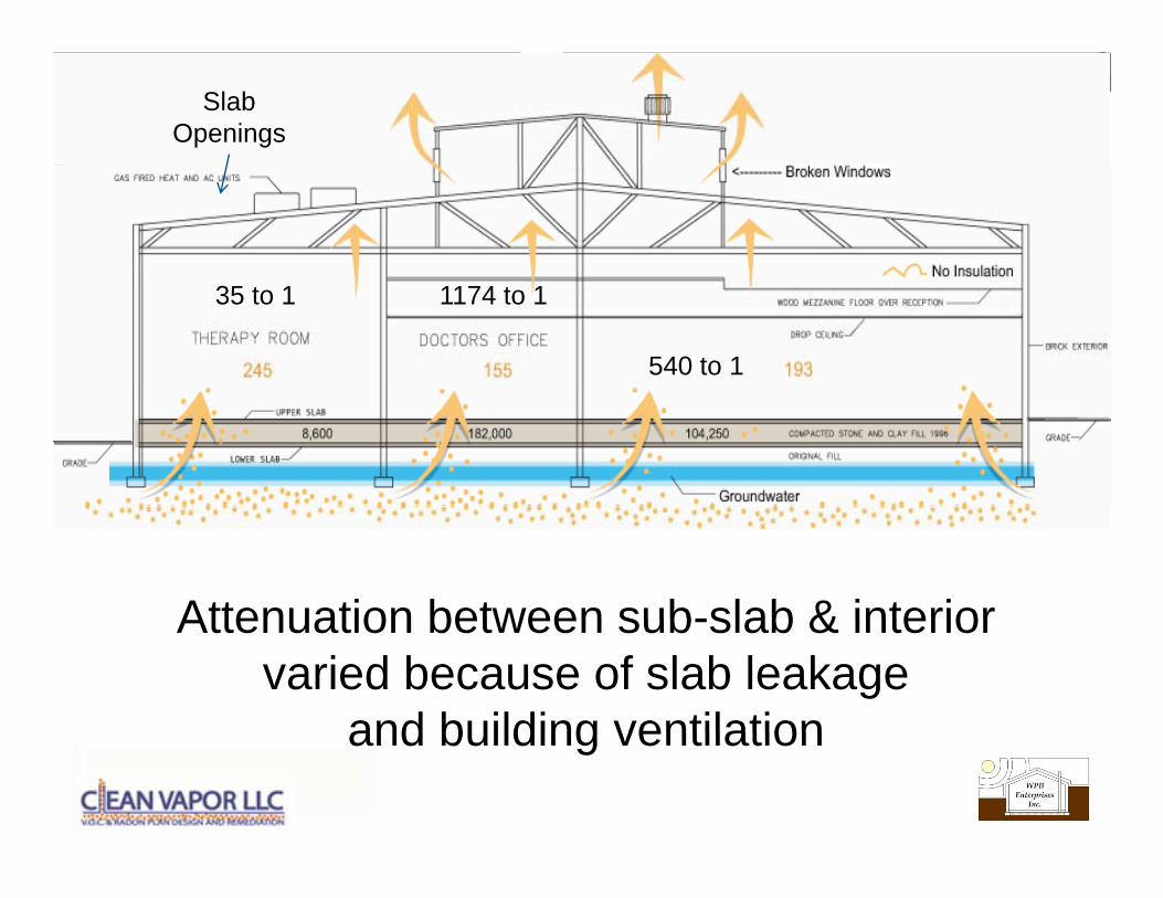
Slab Openings
540 to 1
1174 to 135 to 1
Attenuation between sub-slab & interiorAttenuation between sub-slab & interior varied because of slab leakage
and building ventilationand building ventilation

Diagnostic Investigation g g
2.5 inchDiagnostic Suction Point
Measuring Airflow andSub Slab Static VacuumDiagnostic Suction Point Sub Slab Static Vacuum
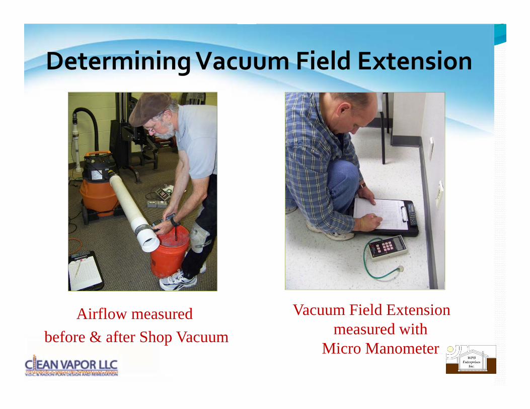
Determining Vacuum Field Extension g
Airflow measuredb f & ft Sh V
Vacuum Field Extension measured withbefore & after Shop Vacuum measured with
Micro Manometer

50 0
Bench Test of 6.5 HP Shop Vacuum versus Common Fans
40.0
45.0
50.0
)
Max.Vacuum 47.5"
Test date
25.0
30.0
35.0
uum
(in
H2 O
) Test date08/31/10
ShopVac
HS5000
10.0
15.0
20.0
Sta
tic V
acu
Max.159 CFM
HS5000
HS2000
Force
0.0
5.0
0 20 40 60 80 100 120 140 160
Flow Rate SCFM
Force Fan
Shop Vacuum may Over Predict System Performance
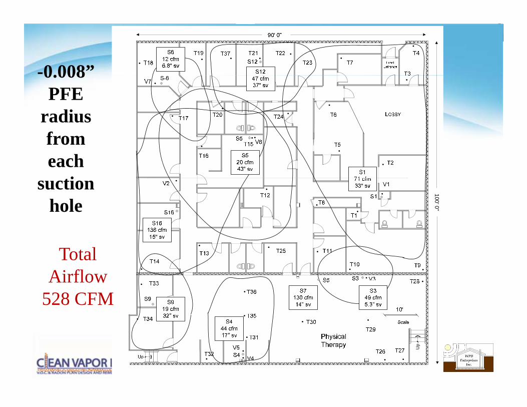
-0.008”0.008 PFE
radius from each
tisuctionhole
100' 0"
Total AirflowAirflow
528 CFM
Up

Choosing Blowersg
Group Convention Blowers OR Experiment with Radial Blowers
Building required 600+ CFM

Blowers were Benched Tested to Develop Performance Curvesp
•Resistance is applied as:Static VacuumAirflowElectrical Power Consumption
is measuredis measured.
Results are available at ww.WPB-Radon.com

400020 0
Flow Tech Fan 40/75 with 1.5 HP Single Phase Motor 40/75 1.5 HP fan wattageTest date12/1/09
2800
3200
3600
4000
14 0
16.0
18.0
20.0 FTF 40/75
Motor OverMotor Service Range
1600
2000
2400
2800
8 0
10.0
12.0
14.0
Wat
tage
uum
(In.
H2 O
)
Max
Motor Over Amperage
Motor Service Range
400
800
1200
1600
2 0
4.0
6.0
8.0 W
Sta
tic V
acu Max.
750 CFMw/20' of 4" pipe
1900 watts300 cfm
1.15 service factor = 2185 watts @ 375 CFM
0
400
0.0
2.0
0 50 100 150 200 250 300 350 400 450 500 550 600 650 700 750 800
Flow Rate CFM
300 cfm17" VACUUM
Bench Test of FTF 40/75Note: Service Factor Limitation

CFM01/13/2010
S7 Soil resistance versus Fan Airflow
1000CFM
600
Maximum airflow FT 40/75 350 cfm
100Force 120 ÷ 4 = 30 cfm
200
3007 suctions 4 suctions
FT 40/75
FT 40/75 350 ÷ 7 = 57 cfm
100
40
Force 120 ÷ 4 = 30 cfm
2 suctionsHS2000 68 ÷ 2 = 34 cfm
102" " 6 " 8 ""
2 suctions
"6""
HS2000Force
HS5000131 cfm during
PFE test1 10 100
Pressure drop in inches of water versus airflow
2 40 60" 80"8" 20"6"4"
S7 Therapy Rm = High Flow Suction Hole

01/13/2010
S1 Soil resistance versus Fan Airflow
100
CFM
HS 2000
80FT 40/75 88 ÷ 2 = 44 cfm
01/13/2010
ForceHS 2000 FT 4075
40
60
HS2000 50 ÷ 2 = 25 cfmHS 5000
2 suctions
30HS fans 35 ÷ 1 = 35 cfm
20
1 suctionForce 19 ÷ 1 = 19 cfm
71 cfm duringPFE test
101 10 100
Pressure drop in inches of water versus airflow2" 40" 60" 80"8" 20"4" 6"
PFE test
S1 = Medium Flow Suction Hole
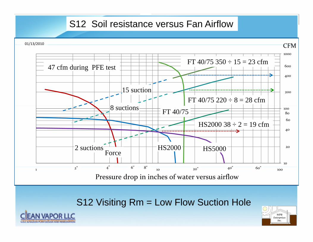
S12 Soil resistance versus Fan Airflow
CFM01/13/2010
1000
CFM
600
400
FT 40/75 350 ÷ 15 = 23 cfm
01/13/2010
47 cfm during PFE test
20015 suction
400
8 iFT 40/75 220 ÷ 8 = 28 cfm
100
40
60
80FT 40/758 suctions
HS2000 38 ÷ 2 = 19 cfm
10
20
6"
HS2000Force
" 6 "8"
2 suctions
4""
HS5000
1 10 100
Pressure drop in inches of water versus airflow6 20" 40" 60"8"42"
S12 Visiting Rm = Low Flow Suction Hole
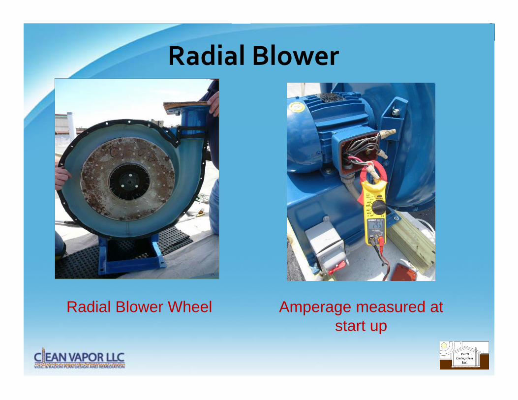
Radial Blower
Radial Blower Wheel Amperage measured at start upstart up
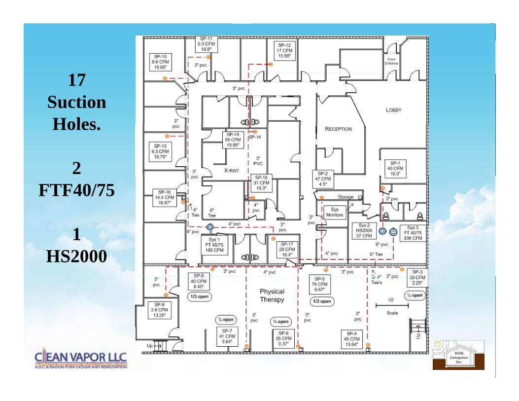
1717SuctionHolesHoles.
2 FTF40/75
1HS2000

Building Interiorg
Patient Exam RoomPi d
Therapy Room:Pipe left exposed
Pipe encasedPerimeter was sealed
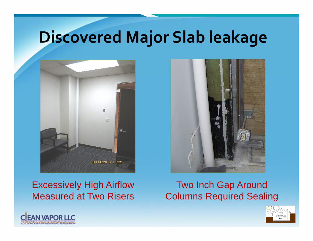
Discovered Major Slab leakagej g
Excessively High Airflow Measured at Two Risers
Two Inch Gap Around Columns Required SealingMeasured at Two Risers Columns Required Sealing

Maximizing Vacuum by Adjusting Airflowg y j g
Measuring Riser Pipe Airflow with a Pitot Tube
Slide Valves Regulate Riser Pipe Airflowwith a Pitot Tube Riser Pipe Airflow
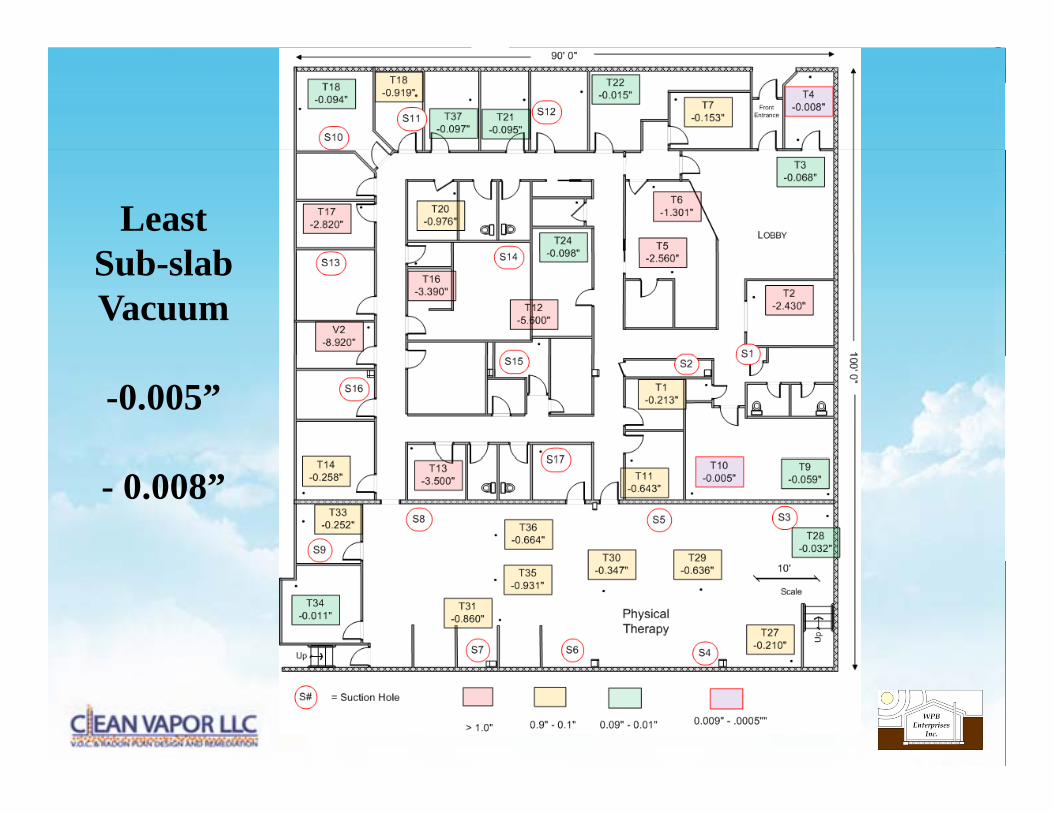
LeastS b l bSub-slabVacuum
-0.005”
- 0.008”

Fan & Energy Consumption ComparisonRadial Blowers
Fan CFM amps Amps amp volts watts $/KwHr Cost/YrSys 2 HS2000 40 1.82 115 209.3 0.18 $330Sys 1 FTF4075 160 3 26 3 11 2 99 230 1076 4 0 18 $1 697
Radial Blowers
Sys 1 FTF4075 160 3.26 3.11 2.99 230 1076.4 0.18 $1,697Sys 3 FTF4075 352 4.23 4.01 4.51 230 1466.25 0.18 $2,312
Total CFM 552 Fan cost $5800 Yearly Elec $ $4,339
C h $362Conventional Blowers Cost per month = $362Typical ASD Fans
Fan CFM amp Volts watts $/KwHr Cost/Yr # Fans Cost/Yr
Conventional Blowers
HS5000 30 3.8 115 437 0.18 $689 4 $2,756HS2000 40 1.8 115 207 0.18 $326 3 $979
Force 100 2 115 230 0.18 $363 3 $1,087T t l CFM 540 F t $9600 Y l El $ $4 823Total CFM 540 Fan cost $9600 Yearly Elec $ $4,823
Cost per month = $402
• Building Evaluation and Vacuum Field Extension Testing is Critical to Optimizing a Vapor Mitigation System p g p g y
• Using Fewer Blowers Reduces Energy and Installation cost
• Soil Resistance vs Blower Performance graphs help determine g p pOptimum Blower & Maximum # of Suctions
• System Optimized by Retesting Soil Resistance after Pit Excavation
• Sealing is Critical to System Performance
• Must NOT exceed Motor Service Factor
• Radial Blowers are an Effective Alternative to Multiple Regenerative Blowers for Low Permeability Soils