high-precision, high-accuracy timekeeping in distributed
TRANSCRIPT

INTERNATIONAL HYDROGRAPHIC REVIEW Vol. 9, No. 1 April 2008
High-Precision, High-Accuracy Timekeeping in Distributed Survey Systems
B. R. Calder, LCDR R. T. Brennan, J. Marcus, C. Malzone, and P. Canter
Abstract
_J___.r- Article
Accurate and precise timekeeping between computers in a distrib
uted survey system is essential to ensure adequate data quality,
especially with Multibeam Echosounders (MBES) which can otherwise suffer from significant motion artefacts. We show that clock synchronisation on the order of
100-150ns (rms) is readily achievable in a modern MBES-based survey system utilising an Ethernet-based time synchronisation mechanism and some custom time
keeping software. We also show that improving the timekeeping eliminates motion
artefacts in the observed bathymetry, and simplifies the patch-test procedure.
Resume II est essentiel d'avoir un chronometrage exact et precis entre ordi
nateurs dans un systeme integre pour les /eves hydrographiques afin d'assurer une qualite des donnees appropriee notamment pour les sondeurs multi
faisceaux (MBES) qui, dans le cas contraire, peuvent patir de perturbations significatives /iees au mouvement. Nous montrons qu'une synchronisation des horloges de
/'ordre de 100 a 150ns (valeur quadratique moyenne) est facilement obtenue dans un systeme de /eves moderne reposant sur les MBES et utilisant un mecanisme
de synchronisation du temps dans un reseau Ethernet et un logiciel specifique de chronometrage. Nous demontrons egalement que /'amelioration du chronometrage permet de supprimer certaines perturbations /iees au mouvement dans Ia bath
ymetrie observee et de simplifier Ia procedure d'essai par plage.
Resumen Para asegurar una calidad adecuada de los datos es esencia/ una exacta y precisa mantenci6n de Ia hora entre ordenadores en un
sistema de levantamiento distribuido, especia/mente con Sondadores Acusticos Multihaz (MBES), que sino pueden experimentar /as consecuencias de un significativo movimiento de sus artefactos. Mostramos que Ia sincronizaci6n de un reloj en e/
orden de 100-150ns (rms) puede 1/evarse a cabo facilmente en un sistema moderno de levantamientos efectuados mediante MBES, utilizando un mecanismo Ethernet basado en Ia sincronizaci6n del tiempo yen a/gun programa de mantenci6n de Ia hora adaptado. Tambien mostramos que mejorando Ia mantenci6n de Ia hora se
elimina el movimiento de los artefactos en Ia batimetrfa observada, y simplifica el procedimiento de pruebas en parches.
9

INTERNATIONAL HYDROGRAPHIC REVIEW
All modern hydrographic survey systems are distributed: data is generated in multiple instruments and then integrated to generate the final depth estimates. For this integration to operate correctly the data must share a common time epoch or at the very least the various data streams must have time epochs with a fixed relationship (i.e., a known, constant offset between indicated times). Failure to generate a stable time epoch within the system results in data artefacts, frequently motion-related.
There are two options for epoch generation in current use: transfer all data to one computer system, and apply the local clock's sense of time at reception; or synchronise the local clock at each computer in the survey system to a uniform epoch and apply timestamps to data as they are created. The former Single Global Clock (SGC) scheme guarantees a uniform epoch (since there is only one in use), but suffers significantly from variable delays in data transfer. It has now largely been superseded by schemes of the latter 'distributed timebase' form due to increasing accuracy and precision requirements in modern shallow-water ultra-high resolution survey systems.
Distributed time base schemes are technically more difficult to achieve, but provide significant improvements in performance. These schemes have two essential components: a
(a) Distributed
Serial Message
(b) Hybrid
Local Clock
IMU
IMU
high-resolution 'now' signal to indicate a par- Figure 1: Models of timekeeping. The Distributed Serial Message,
ticular time (typically the start of a second); (a), avoids transmission latency by timestamping all data locally,
and a reference message containing the absolute time information (i.e., which second has been, or is going to be, ticked at the sig-
but suffers from latency in distribution of the timestamps and does
not scale well; the Hybrid Local Clock, (b), achieves high accuracy
through custom hardware clocks, but can have significant complex-
nal). The simplest such scheme is the Dis- ity and cost in wiring and scaling.
tributed Serial Message, Figure 1(a). Here, the 'now' signal is implied from the start of the serial message being sent from a master time source (typically a GPS receiver or GPS-integrated motion sensor), with the absolute reference encoded in this signal. Properly implemented (D. Lockhart, personal communication, 2005), this message should have fixed latency with respect to the true 'now' instant, which can be estimated and corrected by (modified) patch-test procedures (NOAA, 2006). Ensuring that this is the case is difficult in practice, and requires very careful control of the messaging priority from
10
the time source, distribution of the messages, and reception contro~ at the receivers. Cabling con-straints limit the scalability of this solution.
A more complex scheme is the Hybrid Local Clock (HLC), Figure 1(b). Here, the 'now' signal is provided by the 1PPS (Pulse Per Second) hardware signal available from most GPS receivers (or GPS-integrat-ed motion sensors), and is used to discipline both the computer's local clock and a separate high-resolution hardware counter that provides millisecond
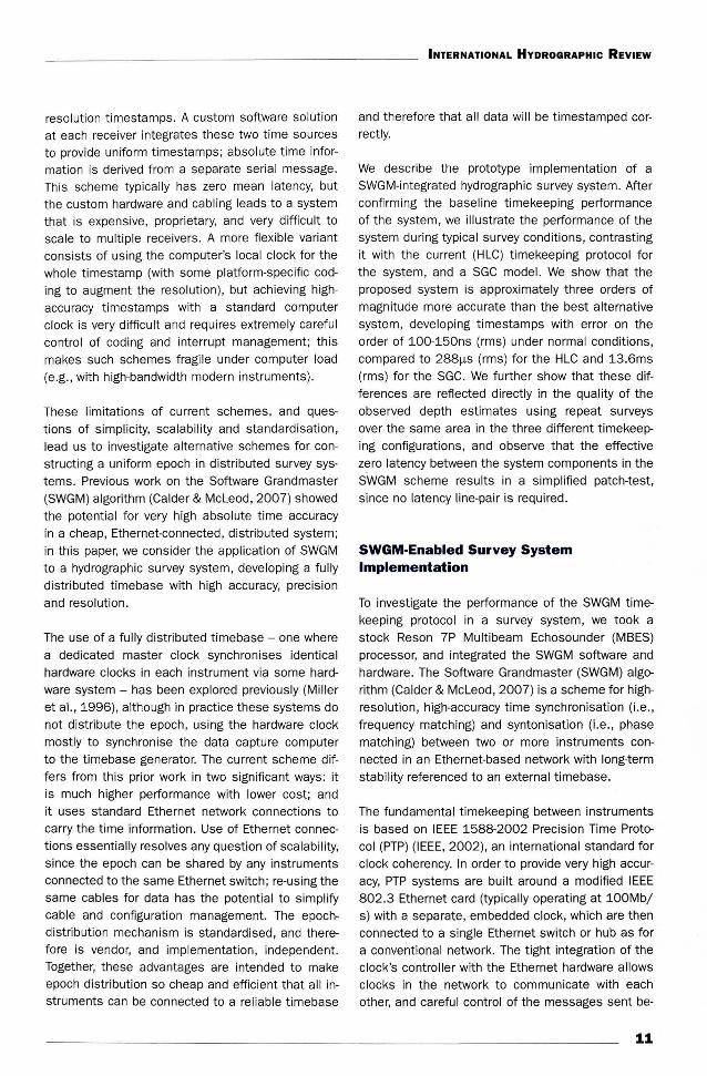
resolution timestamps. A custom software solution at each receiver integrates these two time sources to provide uniform timestamps; absolute time information is derived from a separate serial message . This scheme typically has zero mean latency, but the custom hardware and cabling leads to a system that is expensive, proprietary, and very difficult to scale to multiple receivers . A more flexible variant consists of using the computer's local clock for the who le timestamp (with some platform-specific coding to augment the resolution}, but achieving highaccuracy timestamps with a standard computer clock is very difficult and requires extremely careful control of coding and interrupt management; this makes such schemes fragile under computer load (e.g., with high-bandwidth modern instruments).
These limitations of current schemes, and questions of simplicity, scalability and standardisation, lead us to investigate alternative schemes for constructing a uniform epoch in distributed survey systems. Previous work on the Software Grandmaster (SWGM) algorithm (Calder & Mcleod , 2007) showed the potential for very high absolute time accuracy in a cheap, Ethernet-connected, distributed system; in this paper, we consider the application of SWGM to a hydrographic survey system, developing a fully distributed timebase with high accuracy, precision and resolution.
The use of a fully distributed timebase- one where a dedicated master clock synchronises identical hardware clocks in each instrument via some hardware system - has been explored previously (Miller et al., 1996), although in practice these systems do not distribute the epoch, using the hardware clock mostly to synchronise the data capture computer to the timebase generator. The current scheme differs from this prior work in two significant ways: it is much higher performance with lower cost; and it uses standard Ethernet network connections to carry the time information. Use of Ethernet connections essentially resolves any question of scalability, since the epoch can be shared by any instruments connected to the same Ethernet switch; re-using the same cables for data has the potential to simplify cable and configuration management. The epochdistribution mechanism is standardised, and therefore is vendor, and implementation, independent. Together, these advantages are intended to make epoch distribution so cheap and efficient that all instruments can be connected to a reliable timebase
INTERNATIONAL HYDROGRAPHIC REVIEW
and therefore that all data will be timestamped correctly.
We describe the prototype implementation of a SWGM-integrated hydrographic survey system. After confirming the baseline timekeeping performance of the system, we illustrate the performance of the system during typical survey conditions, contrasting it with the current (HlC) timekeeping protocol for the system, and a SGC model. We show that the proposed system is approximately three orders of magnitude more accurate than the best alternative system, developing timestamps with error on the order of 100-150ns (rms) under normal conditions, compared to 288f.lS (rms) for the HlC and 13.6ms (rms) for the SGC. We further show that these differences are reflected directly in the quality of the observed depth estimates using repeat surveys over the same area in the three different timekeeping configurations, and observe that the effective zero latency between the system components in the SWGM scheme results in a simplified patch-test, since no latency line-pair is required.
SWGM-Enabled Survey System Implementation
To investigate the performance of the SWGM timekeeping protocol in a survey system, we took a stock Reson 7P Multibeam Echosounder (MBES) processor, and integrated the SWGM software and hardware. The Software Grandmaster (SWGM) algorithm (Calder & Mcleod, 2007) is a scheme for highresolution, high-accuracy time synchronisation (i.e., frequency matching) and syntonisation (i.e., phase matching) between two or more instruments connected in an Ethernet-based network with long-term stability referenced to an external timebase.
The fundamental timekeeping between instruments is based on IEEE 1588-2002 Precision Time Protocol (PTP) (IEEE, 2002), an international standard for clock coherency. In order to provide very high accuracy, PTP systems are built around a modified IEEE 802 .3 Ethernet card (typically operating at 100Mb/ s) with a separate, embedded clock, which are then connected to a single Ethernet switch or hub as for a conventional network. The tight integration of the clock's controller with the Ethernet hardware allows clocks in the network to communicate with each other, and careful control of the messages sent be-
11

INTERNATIONAL HYDROGRAPHIC REVIEW
(a) 'Pure ' PTP time
base distribution
from IMU's GPS
(b) Software
Grandmaster
timebase
distribution
sss
IMU
CAPTURE
IMU
MBES
manded to start participating in PTP. automatically electing a master clock, and reconfigure themselves if the master becomes unavailable or if a better clock appears in the group. The network is therefore self-configuring and selfhealing, and runs using cheap (<USD500 in 2007 ) hardware that utilise standard Ethernet cables and switches, and which can double as data channels : to the host instrument, the card appears as just another Ethernet adapter.
The PTP system does not guarantee any relationship to an external timebase, or long-term stability of the master clock without extra hardware and/ or software. Ideally, a GPS receiver in the system, or a GPS-integrated motion sensor would provide this service, disciplining its local PTP clock to GPS time which is then automatically distributed through the network by PTP, Figure 2(a). No such system currently exists for survey, however. To resolve this, the SWGM algorithm adds reference to a given timebase by arranging for the 1PPS edge event generated by a GPS-receiver (or GPS-integrated motion sensor) on the UTC seconds tick to be timestamped by the PTP hardware, Figure 2(b) . This very high accuracy timestamp (with uncertainty typically -5ns (rms) in the trial implementation) allows the development of correspondences between PTP master clock time and UTC t ime and hence correction of longterm PTP drift, keeping the PTP clocks locked to UTC t ime. (Absolute reference is provided by
Figure 2: Timebase distribution models for PTP in a hydrographic
survey system. The 'pure' model, (a), distributes UTC from the
an ASCII NMEA message (NMEA, 2002), which has no strong latency requirements save that it should occur isochronously with the 1PPS events to avoid confusion over the correspondence between event ticks and NMEA labels.)
IMU's PTP clock, which is disciplined to the IMU's GPS receiver
clocks. (Crosses indicate local clocks that are disabled in the
configuration.) Until /MUs have this facility, a modified Distributed
Timebase Model is used, (b), with PTP aiding to distribute the
time bases, and Software Grandmaster corrections to provide
UTC timestamps at all component systems.
The correspondences observed at the master clock are distributed to the other clocks over the network so that high-accuracy timestamps can be generated at any clock simply by hav-
tween clocks (which contain timestamps indicating the time that the message was sent according to the local clock) allows the clocks to determine which peer is most reliable, what their relative error is with respect to this peer, and how to correct their local sense of t ime in order to synchronise and syntonise to the peer's timebase. Synchronisations on the order of 75ns (rms) have been reported using standard switches and cabling (National Instruments, 2005). The clocks are essentially autonomous once com-
12
ing the host instrument request timestamps from the SWGM algorithm rather than the host's built-in clock. In previous experiments, timestamps for the same event at different machines with variability on the order of 85ns (rms) were observed (Calder & McLeod, 2007 ).
The test system added a National Instruments (Austin , TX) PCI-1588 PTP Ethernet card (National Instruments, 2005) to the stock Reson 7P processor

to implement PTP; a second 1/0 Module was also added to the 7P processor so that a hardware trigger signal could be generated whenever the sonar emitted acoustic energy (to facilitate high-accuracy timestamping of ping times). We then integrated the SWGM software with Reson's 7kCenter MBES control software, so that differing versions of 7kCenter could be used to implement different timekeep·mg configurations, facilitating comparison of their rela-
(a) SWGM & SGC Modes
DATA CAPnJRE
DB-9 Q---1--'Z""DA"!J
RI-4S DATA
POS/MV 320 PCS
DATA RI-4S
INTERNATIONAL HYDROGRAPHIC REVIEW
tive abilities to maintain a common epoch between different components of the system. The only modification to the stock 7kCenter software other than interfacing the SWGM Application Programming Interface (API) was to generate a separate file with timestamps from the SWGM algorithm: the internal representation of times in the Reson 7000-series datagrams (Reson, 2006) cannot preserve the nanosecond resolution of the SWGM timestamps. These
data were re-integrated in post-processing.
TRIGGER PING _F
With these modifications, the survey system had two basic configurations, Figure 3. For SWGM-based timekeeping, Figure 3(a) was used; by ignoring the data tiles' embedded timestamps and using those applied at the capture computer this can also be used to simulate SGC timekeeping (although this is an atypical configuration for this equipment, and not recommended by the manufacturer). Note that a second hardware input on the Reson 7P processor's PCI-1588 card was used to hardware timestamp the ping events from the sonar, providing highaccuracy groundtruth for when the ping actually occurred; these timestamps are stored internally in the card and later are recovered by the modified 7kCenter control software. For testing purposes, we also monitored the 1PPS event at the 7P processor and the data capture computer (independent of the SWGM algorithm), since it allowed us to monitor baseline performance of the clocks.
!l---.1'--------------\J! PCI-1588ru
~-~~= PTP
(b) HLC Mode
DATA CAPnJRE
TIME DEJ..g
RJ.4S DATA DATA RI-4S
Figure 3: Survey suite configurations for the experiments: (a) Nominal
performance of the integrated Reson/SWGM software, and Baseline
petformance in SGC mode; and (b) Baseline petformance in HLC mode.
The conventional timing mode for Reson 7P systems is a hybrid hardware; software system, Figure 3(b), where the 1PPS signal is used to synchronise the 7P's local clock and a separate millisecond hardware timer. In this configuration, we used the PCI-1588 hardware to provide groundtruth ping times, but otherwise ran stock hardware and software. Note that no redundant monitoring of the 1PPS events at the 7P was carried out in this configuration due to fan-out limitations on the 1PPS signal under load from the two inputs of the 7P processor.
13
INTERNATIONAL HYDROGRAPHIC REVIEW
Device Make Model Serial /Version Number
Multibeam Topside Processor Reson 7P 51515
Multibeam Topside Software Res on N/ A 2.13.8.2
Multibeam Sonar Head Reson 7125 (400kHz) 5004346
Multibeam Sonar Head Firmware Reson N/ A MR3
Data Capture Computer Dell Dimension 9150 EM8FM91
Data Capture Software Triton Imaging ISIS/SONAR 7.0.41
Motion Sensor Applanix POS/ MV 320 V4 2084
Motion Sensor Firmware Applanix N/ A 2.8-6
GPS Differential Corrections Receiver Trimble DSM212L -
Sound Speed Profiler SeaBird SBE19 19P37217-4677
Sonar Head Sound Speed ODOM Digibar 98376
Timing Ethernet Switch LinkSys EG008W RDV004100759
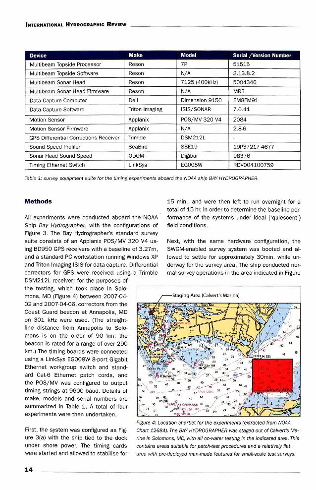
Table 1: survey equipment suite for the timing experiments aboard the NOAA ship BAY HYDROGRAPHER.
Methods
All experiments were conducted aboard the NOAA Ship Bay Hydrographer, with the configurations of Figure 3. The Bay Hydrographer's standard survey suite consists of an Applanix POS/MV 320 V4 using BD950 GPS receivers with a baseline of 3 .27m, and a standard PC workstation running Windows XP and Triton Imaging ISIS for data capture. Differential correctors for GPS were received using a Trimble DSM212L receiver ; for the purposes of the testing, which took place in Solomons, MD (Figure 4) between 2007-04-02 and 2007-04-06, correctors from the Coast Guard beacon at Annapolis, MD on 301 kHz were used. (The straightline distance from Annapolis to Solomons is on the order of 90 km; the beacon is rated for a range of over 290 km.) The timing boards were connected using a LinkSys EG008W 8-port Gigabit Ethernet workgroup switch and standard Cat-6 Ethernet patch cords, and the POS/ MV was configured to output timing strings at 9600 baud . Details of make, models and serial numbers are summarized in Table 1. A total of four experiments were then undertaken.
15 min ., and were then left to run overnight for a total of 15 hr. in order to determine the baseline performance of the systems under ideal ('quiescent') field conditions.
Next, with the same hardware configuration, the SWGM-enabled survey system was booted and allowed to settle for approximately 30min. while underway for the survey area. The ship conducted normal survey operations in the area indicated in Figure
First, the system was configured as Figure 3(a) with the ship tied to the dock under shore power. The timing cards were started and allowed to stabilise for
Figure 4: Location chartlet for the experiments (extracted from NOAA
Chart 12684). The BAY HYDROGRAPHER was staged out of Calvert's Ma
rine in Solomons, MD, with all on-water testing in the indicated area. This
contains areas suitable for patch-test procedures and a relatively flat
area with pre-deployed man-made features for small-scale test surveys.
14

INTERNATIONAL HYDROGRAPHIC REVIEW
0.02 ~----,--..,-----,----.,--~:-----,---o;:::====:::!:::=====r::::==::;-J 0 Quiescent Master
O.DI B
0.016
0.01 4
"" 0.012 -,;
~ .~ O.D\ :5 2 0 0: 0.008
0.006
0.004
: - e- Quiescent Subordinate - Active Master
u Active Subordinate
UTC Second Prediction Error (ns)
Figure 5: Probability density estimates for the observed error in UTC seconds prediction for master and subordinate clocks
in quiescent and active tests. The master clock behavior appears to be significantly better due to the focal scheduling ef
fect; the subordinate clock behavior is more indicative of the actual performance of the timing scheme.
4, starting with a sound speed profile (SSP) cast and a conventional patch-test, for a total of approximately 3 hr. This data allows testing of baseline performance under typical ('active ') field conditions, and assessment of the accuracy of SWGM-based timestamping in the Reson 7P processor.
Next, the Reson 7P processor was configured with stock 7kCenter controller software, all time synchronisation was removed, forming a SGC system. The systems were allowed to settle for over 30 min . and the previous experiment was repeated (SSP cast, patch-test, area survey) for a total of approximately 1.5 hr. of survey time . A stand-alone version of the SWGM algorithm was run on both 7P processor and data capture computer to provide groundtruth timestamps and performance monitoring.
Finally, the system was configured as Figure 3(b), the Reson 7P processor's conventional timing mode. Stock 7kCenter software was utilised, and stand-alone SWGM processes were run on the 7P and data capture computer as before; the same synchronisation and survey procedures were repeated . Total survey operations time was approximately 1.5hr.
Results Baseline Performance
The baseline performance data was summarised by computing the difference between the observed time of the 1PPS events and the (known, ideal) UTC time for the event, taking care to preserve the nanosecond resolution of the data throughout, and then computing the probability density of the errors, Figure 5. (Note that these are true errors, since the actual UTC time is known, rather than uncertainty estimates.) The difference in performance between master (data capture computer) and subordinate (7P processor) clocks is due to a scheduling anomaly within the master clock system: on occasion, the SWGM correspondence packet is incorporated into the algorithm's notion of the current time ahead of the software 's request to correct the PTP times to UTC. This leads to anomalously low correction errors (the algorithm has, in essence, 'perfect' knowledge of the timestamp required). The performance of the subordinate clock is more important, and more typical of the performance for randomly distributed timestamp requests.
The quiescent performance (i.e., while tied to the dock under shore power) is 36 ns (rms) and 144 ns (rms) for master and subordinate clocks, respect-
15

INTERNATIONAL HYDROGRAPHIC REVIEW
ively; for active performance (i.e., underway with the engines, genset and sonar operating), it is 30 ns (rms) and 107 ns (rms). Some 'bursty' performance of error in the master clock is observed in timeseries plots of error; this is most like ly due to loca l thermal shock with in the data capture computer: due to space limitations, the PCI-1588 card was installed next to the graphics ca rd , which generates a lot of heat and employs active cooling during operations. The effect is small, however, and massively overwhelmed by the natural variability of the cards at the subord inate clock and therefore is not observed there. The small difference between quiescent and active performance in the subordinate clock is most likely due to statistica l fluctuation of the estimates (i.e ., standard error) and the difference in run-time of the tests, rather than any true difference in the behaviour of the algorithm while quiescent and active.
The long-term stability of the clocks and their driving noise performance can be determined from the Allan variance (Allan, 1987), a common measure of clock stabi lity. In principle, the Allan variance describes the expected difference between true and indicated time over specified time duration , averaged for the time between observations:
(1)
of the clock 's indicated time over the given duration and hence of its stability. (Note that although equation 1 computes the Allan variance, the Allan deviation - defined as the positive square root of the variance - is more commonly used in practice, and is the norm through the remainder of thi s work.) Figure 6 shows the performance of the clocks in quiescent and active modes, based on the PTP and corrected UTC t imes. The base performance of the clocks is indicated by the PTP times, which clearly shows the expected long-term drift. (Note that the Allan deviation shows drift averaged over the observation period; similar deviations over longer periods therefore imply larger absolute drift.) The subordinate clock follows the master and therefore has slightly elevated Allan deviation. The UTC Allan deviation shows significantly improved performance with lower drift: in effect, the clocks now fo llow the 1PPS signals from the POS/MV exactly. This does not imply that they are now perfect, just that they follow the 1PPS signals without significant drift over
·the observation period.
SWGM-Enabled Timekeeping
There are two modes for timestamp generation in any survey system: a hardware trigger causes a timestamp to be generated , or some data 's generation is noted in software, and a timestamp is requested from the loca l clock (e.g. , the SWGMwrapped PTP hardware) . We call these hardware and software timestamps, respectively; they have
(where there are N observations of time, xk, at in- very different performance characteristics which tervals of -rs .) which is a measure of the likely drift are summarised in Figure 7.
1 0 '~';-,. --~-',,.,------,'7,. --~~,.,...--~-,..,.,. ---' ... ~Thwl.•!•)
(a) Quiescent Testing
j,. ··~
j
IO ~cf~---~ .. ;-, ---~,1,-------=o,,----' "-~l'lrM.1!1)
(b) Active Testing
Figure 6: Allan deviation estimates for the quiescent and active tests, showing the long-term stability of the clocks. The PTP
performance is the base performance of the hardware oscillators in the PCI-1588 cards; the UTC performance shows that
the long-term drift of the oscillators has been effectively cancelled by the SWGM.
16

-------------- _ INTERNATIONAL HYDROGRAPHIC REVIEW
The SWGM clock is the best available t imekeeper, and therefore there is no absolute reference to which the hardware timestamps can be compared. We have therefore summarised the performance using the uncertainties estimated by the SWGM algorithm for these timestamps, Figure 7(a), which have previously been shown (Calder & Mcleod , 2007 ) to correspond we ll to the observed errors in timestamps (where such errors are observable). The results here show a spread of 100-300ns (rms) wi th moda l value of 150ns (rms). The slight increase over the baseline performance occurs because the timestamps being generated are distributed randomly with respect to the 1PPS
timebase.
(a) Estimated Hardware Latency PDF
(c) Ping Frequency
The true error of the software t imestamps can be computed by comparison against the hardware timestamps for the same pings, Figure 7(b). A mean error of 5.007ms has been removed to compensate for the (intentional) delay between ping and generation of the hardware trigger imposed by the current Reson 7P hardware. The observed errors, standard deviation 28)lS (rms), are significantly higher than hardware timestamps because in this mode t he 7P processor can spend a significant amount of time between the instant that the 7kCenter software sends the 'ping now' command to the MBES hardware and when it final ly executes the request for timestamp from the SWGM algorithm, depending on loading of the CPU , higher priority tasks (e.g., disc
I f
(b) Observed Software Latency PDF
(d) Estimated Software Latency PDF
Figure 7: Active performance for the SWGM-enabled Reson 7P Processor. The hardware timestamp latency, (a), is in the
range 100-300ns (rms) with modal value of approximately 150ns (rms), corresponding to the performance of the underly
ing SWGM algorithm in distributing the timebase. The observed software timestamp error, however, is approximately 28 ps
(rms), (b), with asymmetry probably due to differences in loading at different ping frequencies, (c); the magnitude with re
spect to the hardware values implies that the increase is due to scheduling and priority issues within the 7P processor. The
uncertainties predicted for the software timestamps, (d), match the errors observed in practice and indicate that although
the long-term performance might be higher, the instantaneous uncertainty is likely somewhat smaller.
17

INTERNATIONAL HYDROGRAPHIC REVIEW
\ ~ (\'i0/~4 . .. "'
~~~- - ~-~·ol'-·' --:-, --=7..,."'-'-"-'-~-:-!;;"'---.j, btltN\fd Z--~U~!,.I
(a) SGC Mode
1.2 • 10 ..
f r
{b) HLC Mode
I
J
Figure 8: Estimates of latency pdf for the SGC, (a), and HLC, (b), models. The scale of latency is significantly higher for
the SGC model than for the HLC model, as expected, and both are significantly higher than the SWGM-enabled Reson 7P
Processor, as expected. The shape of the HLC mode pdf suggests that the majority of the error is quantization noise, rather
than true clock error.
access) or other OS housekeeping requirements. The SWGM-enabled 7kCenter software was designed to minimise these effects as much as possible, but they are an inevitable consequence of working with a general purpose, non-realtime computer system. The asymmetry of the distribution of errors is primarily due to CPU loading effects caused by variability of ping rates, Figure 7(c): higher ping rates require more CPU/ disc effort, increase the probability of a load-induced latency in obtaining the timestamp, and therefore on average increase the potential for error in timestamp generation.
Conventional Timekeeping
The error in timestamping for the SGC and HLC experiments were computed by comparison against the SWGM hardware timestamps for the corresponding ping events, and are summarised in Figure 8 . The SGC system was found to have no stable mean error as outlined above, and therefore a simple mean offset was applied; the estimate is therefore an estimate of va riability rather than true error. An approximately symmetric distribution of error is observed , Figure 8(a), with standard deviation 13.6ms, indicating very significant variability in timestamping caused by local clock drift, interrupt latency at the data capture computer, and loading effects.
The HLC system, Figure 8(b), shows an essentially uniform distribution of error with magnitude ±0.5ms which is caused by truncation of the timestamp to 1ms resolution by the hardware counter in the system: the system is quantisation noise limited . The actual timekeeping performance of the system
18
is unknown and unknowable; it is certainly sub-millisecond, however, and possibly on the scale of a few tens of microseconds since otherwise greater variabil ity than just the quantisation noise should be observed. (The theoretica l standard deviation of quantisation noise is 288.71-J.S; the estimated sample standard deviation is 2881-J.S.)
Timestamp Error Stability
The stability of the errors in timestamps was estimated by removing the global mean from each of the three experimental signals and then computing the root mean square value of the residual in windows throughout the signal. For the SWGM-enabled system using software timestamps (so that true errors can be observed), the windows were 10 min. in duration, Figure 9(a); for SGC and HLC systems (Figure 9(b) and (c) respectively) a continuous record was not available, so the estimates were computed for each contiguous segment of available data. This ana lysis approximates the effect of removing a fixed latency through a patch-test, and it is evident that the SWGM and HLC systems are stable at the values observed globally, but the SGC system varies significantly with time. The potential for uncorrectable latency-driven motion artefacts is therefore significantly higher for the SGC model of timekeeping.
Observed Bathymetry Bathymetric data were recorded in the field in XTF format (Triton Imaging, 2007). Hardware timestamps for the SWGM-enabled system were re-inserted into the XTF data from the higher-resolution raw timestamp files in post-processing. The data were

INTERNATIONAL HYDROGRAPHIC REVIEW
60
\ \
~ li 10
I -10
-20 L_-::10'::-oo ----:,ooo::::-----:3000:::!=---::,ooo'::-----:,ooo::::-----:eooo:::!=---::,ooo'::-----:aooo;!;;;;-- oooo::;!;:;;-____J Time alnce elan or tuperlment {s)
(a) SWGM-enabled Software Mode
35 ,---.--.--~--,---.---.--.---,
(b) SGC Mode
~ \
~~-~m~~1000~-~1m~----:2000=-~,m~-3000=-~~=---::~'::-~,m· Time line. •tert ol txptrlment (1)
(c) HLC Mode
Figure 9: Variability of latency standard deviation across experiments. The vari
ability of latency can change considerably as a function of time for the SGC mode,
leading to difficulties with correction, although SWGM and HLC modes of timekeep
ing are essentially stable at their globally estimated error level.
processed using CARIS HIPS software, v6.0, in a conventional hydrographic processing chain. A standard data-driven patch test (Godin, 1997) was implemented save that for the SWGM-enabled system we assumed a priori that the latency was zero and did not attempt to determine it from the data.
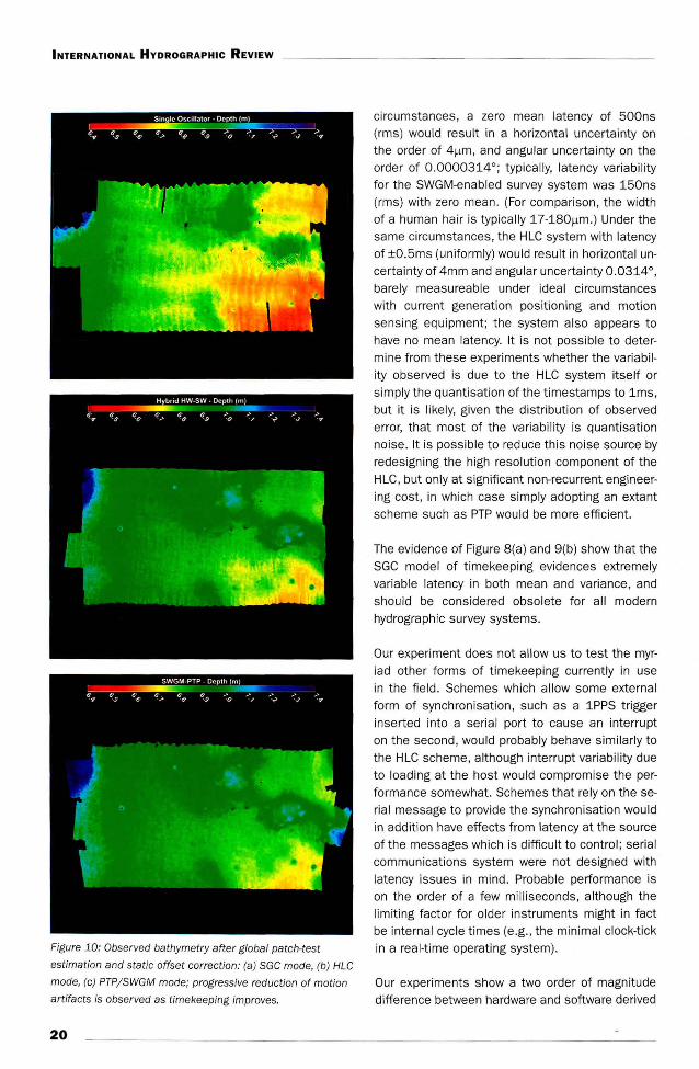
To illustrate the effects of improved timekeeping, the data were formed into bathymetric surfaces at a resolution of 0.25m in -7m depth over an area of approximately 465x300m (projected in UTM zone 18N) and are shown sun
illuminated from the northeast (at vertical exaggeration of 3) in Figure 10. It is clear that the significant motion artefacts observed in the SGC system are heavily reduced with HLC
timing, and virtually eliminated with SWGM timing. There is a small residual effect in the SWGM data that is barely visible with close inspection, but this may be caused by, e.g.,
residual differential motion of IMU and MBES due to the Bay
Hydrographer's knuckle-boom over-the-side deployment system. Subjectively, determination of patch-test parameters appeared to be simpler with the SWGM timing system, since there are fewer unknowns to be adjusted.
Discussion
Consider an , admittedly extreme, survey scenario of a launch travelling at 15 kts while undergoing roll/pitch motion with amplitude 10° and period 1Hz; an uncomfortable day's surveying. Under these
19
INTERNATIONAL HYDROGRAPHIC REVIEW
Figure 10: Observed bathymetry after global patch-test
estimation and static offset correction: (a) SGC mode, (b) HLC
mode, (c) PTPjSWGM mode; progressive reduction of motion
artifacts is observed as timekeeping improves.
20
circumstances, a zero mean latency of 500ns (rms) would result in a horizontal uncertainty on the order of 4f.Lm, and angular uncertainty on the order of 0.0000314°; typically, latency variability for the SWGM-enabled survey system was 150ns (rms) with zero mean. (For comparison, the width of a human hair is typically 17-180f.Lm.) Under the same circumstances, the HLC system with latency of ±0.5ms (uniformly) would result in horizontal uncertainty of 4mm and angular uncertainty 0.0314°, barely measureable under ideal circumstances with current generation positioning and motion sensing equ ipment; the system also appears to have no mean latency. It is not possible to determine from these experiments whether the variability observed is due to the HLC system itself or simply the quantisation of the timestamps to 1ms, but it is likely, given the distribution of observed error, that most of the variability is quantisation noise. It is possible to reduce this noise source by redesigning the high resolution component of the HLC, but only at significant non-recurrent engineering cost, in which case simply adopting an extant scheme such as PTP would be more efficient.
The evidence of Figure 8(a) and 9(b) show that the SGC model of timekeeping evidences extremely variable latency in both mean and variance, and should be considered obsolete for all modern hydrographic survey systems.
Our experiment does not allow us to test the myriad other forms of timekeeping currently in use in the field . Schemes which allow some external form of synchronisation, such as a 1PPS trigger inserted into a serial port to cause an interrupt on the second , would probably behave similarly to the HLC scheme, although interrupt variabil ity due to loading at the host would compromise the performance somewhat. Schemes that rely on the serial message to provide the synchronisation would in addition have effects from latency at the source of the messages which is difficult to control; serial communications system were not designed with latency issues in mind . Probable performance is on the order of a few milliseconds, although the limiting factor for older instruments might in fact be internal cyc le times (e.g. , the minimal clock-tick in a real-time operating system).
Our experiments show a two order of magnitude difference between hardware and software derived

timestamps in the SWGM-enabled system. Clearly, for 'dumb' sensors that do not generate a trigger pulse that can be hardware timestamped , this is likely to be the most significant limitation in timestamp uncertainty. (This is also the case for other instruments interfaced to a data capture computer, e.g. , cable counters, or sound speed sensors.) This effect can be somewhat mitigated by careful coding at the capture system, but is li kely to remain at the microseconds leve l. The significance of thi s effect will depend strongly on the type of sensor and the time variability of the measurand.
INTERNATIONAL HYDROGRAPHIC REVIEW
synthesisable IP-cores (MorethaniP. 2007) for creating complete ly custom hardware devices, or even completely in software (Correll et al., 2005). The first two choices provide for methods to routinely construct PTP /SWGM-enabled instruments, while the last would allow simpler instruments to participate in the timekeeping protocol with extremely low cost per unit. The actual performance of a software-only PTP protocol stack will depend critically on how tightly loca l timestamps can be associated with the PTP packets being distributed. Reported performance in non-Microsoft Windows systems can approach the microsecond range, although performance in Micro-
The performance of all oscillators is affected by soft Windows-based systems is likely to be some-many factors in the local environment (e .g., voltage what worse since modifications to the kernel stack stability, local pressure changes, vibration, etc.), but to apply timestamps close to the hardware Ethernet particularly the temperature stability of the system. interface cannot be made. During the experiment the ambient temperature varied from 25-30°C depending on diurnal effects and functionality of the air conditioning system, but we Conclusions observed no significant differences in the performance of the system that were correlated to environmental effects. A small effect was observed in the data capture computer, but this appears to be related to the local environment inside the computer, possibly due to active cooling of the graphics card adjacent to the timing card . Best practice would mandate carefu l arrangement of the computing environment, although the difference due to th is effect is likely to be small and readily outweighed by other effects .
PTP-enabled Ethernet cards can be used for data transport in addition to timing signals, although high-rate data throughput will inevitably cause higher variability in message transmission latency for the timing messages, and will consequently affect the synchronisation performance of the system. In practice, the potential for this to become a problem is small: most current PTP cards run at 100Mb/ s and are therefore inadequate for high-density data transport in many modern survey systems. It is therefore, unfortunately, un likely that PTP cards will carry anything except low-rate command-and-control traffic until they improve to gigabit performance, at which stage the degradation will be smaller, potentially small enough to be insignificant.
We have focused here on systems using full-sized PCI Ethernet cards, but a PTP system can be implemented in much more compact form in embeddable Ethernet controllers (Intel Corp., 2005), or as VHDL-
We have shown that under typical survey conditions, the proposed PTP/ SWGM time distribution scheme can synchronise multiple instruments to UTC derived from a GPS receiver with zero mean latency and error on the order of 150ns (rms) and therefore can reliably hardware timestamp at any participating instrument with zero mean latency and latency variability on the order of 100-300ns (rms) with modal variability of -150ns (rms) . In software, the latency variability can be up to -28~s (rms) in the long term due to loading in the host CPU, although it is more likely in the 10-15~s (rms) range instantaneously.
We have also shown that timestamps to within ±0.5ms are possible with a current HLC scheme, limited primarily by quantization of timestamps to 1ms levels; the true latency variability is indeterminate (and essentially irrelevant since it cannot be observed at the user level) but likely lower than this. Conventional SGC timestamps were shown to have latency variabilities of up to 14ms (rms) and should therefore be considered inadequate for modern high resolution survey systems.
The proposed system, in addition to significantly better performance than contemporary equivalents, greatly reduces the complexity of integration of the timekeeping components with the survey system. In the ideal case only an Ethernet connection is required. PTP systems that are embeddable (e.g., within Ethernet chipsets) or integrable (e.g., as VHDL
21

INTERNATIONAL HYDROGRAPHIC REVIEW
cores) are readily available ; COTS Ethernet cards with PTP support are also ava ilable at low cost from a number of manufacturers, making this a very attractive solution for high precision and high accuracy timekeeping within hydrographic survey systems .
Acknowledgements
The authors would like to thank NOAA (NMAO and HSTP) for allowing us the use of the Bay Hydrogra
pher to conduct these experiments, LT/ JG Michael Davidson , NOAA (OIC Bay Hydrographer) and Steve Brodet (HSTP) for their skilled , enthusiastic and diligent assistance in running the ship, and Michael Mutschler (Reson) for his dedicated, talented and sustained effort configuring and running the equipment du ring the tests . Use of particular hardware or software does not imply endorsement on the part of the authors or their respective institutions and companies; all relevant trademarks are acknowledged even if not expl icitly ind icated in the text.
References
- Allan , D. W. (1987). Time and frequency (time-domain) characterization, estimation and prediction of precision clocks and oscillators, IEEE Trans.
Ultrasonics, Ferroelectrics and Frequency Control,
34(6):64 7-654. Calder, B. R. and Mcleod, A. (2007). Ultra-Precise Absolute Time Synchronization for Distributed Acquisition Systems. IEEE J. Oceanic Eng. , 32(4) . Correll , K., Barendt, N., and Branicky, M. (2005) . Design Considerations for Software Only Implementations of the IEEE-1588 Precision Time Protocol , in Proc. IEEE 1588 Conference, Zurich: National Institute of Standards and Techno logy. (online: http:/ / ieee1588.nist.gov] . Godin, A. (1997). The Calibration of Shallow Water Multibeam Echo-sounding Systems, MS Thesis, University of New Brunswick. Institute of Electrical and Elect ronic Engineers Instrumentation and Measurement Society (2002). IEEE Standard for a Precision Clock Synchronization
Protocol for Networked Measurement and Control
Systems , ISBN: 0-7381-3370-1. Intel Corporation , (2005). Hardware-Assisted IEEE 1588 Implementation in Intel IXP46X Product Line.
Miller, J. E., Fergusson , J. S., Byrne, J. S. and Simmons, W. S. (1996). Shallow Water Multibeam Hydrography to IHO Standards, Sea Tech ., 37(6): 81-86 . MorethaniP GmbH (2007). A 1588 Tri-Speed Ethernet MAC Core (Product Brief) , Muenchner Strasse 199 , D-85757 , Karlsfeld, Germany [online: http:/ 1 www.morethanip .com/ieee_10_100_1000.htm] . National Instruments, Inc. (2005). PCI-1588 User
Manual . [online : http:j ; www.ni.comj pdfj manuals/ 371670a.pdf].
National Marine Electronics Association (2002). NMEA 0183 Standard for Interfacing Marine Elec
tronic Devices, 3rd Ed . National Oceanographic and Atmospheric Administration (2006). NOAA/ OCS Field Procedures Manu
al , 2nd Ed . Reson, Inc. (2006). SeaBat 7k Data Format, Vol
ume 1, Rev. E. 100 Lopez Road, Goleta, CA, USA. Triton Imaging, Inc. (2007). eXtended Triton Format (XTF), Rev. 21. 125 Westridge Drive, Watsonville , CA.
Biography and Affiliations
Dr. Brian Calder is a Research Assistant Professor at the Center for Coastal and Ocean Mapping and NOAA/ UNH Joint Hydrographic Center at the University of New Hampshire. He graduated MEng and PhD in Electrical and Electronic Engineering from HeriotWatt University in Edinburgh, Scotland in 1994 and 1997 respectively, but was subsequently seduced into sonar signal processing for reasons that are now
obscure. He is a member of the lEE, IEEE, AGU and Hydrographic Society of America, and an Associate Editor for the IEEE Journal of Oceanic Engineering.
Brian Calder Center for Coastal and Ocean Mapping
and NOAA/ UNH Joint Hydrographic Center, University of New Hampshire, Durham NH 03824, USA (brc@ ccom .unh .edu). [Corresponding] Richard Brennan: Hydrographic Systems and Technology Program, NOAA's National Ocean Service, 1315 East West Highway N/ CS11, Silver Spring, MD 20910, USA (richard .t .brennan@noaa .gov). J_ Marcus, C. Malzone: Reson, Inc., 100 Lopez Road , Goleta , CA 93117 , USA Umarcus@reson .com, malzonec@reson .com). Peter Canter: Applanix Corporation , 85 Leek Cres-
[online: http:j / dowload .intel.com/ design; net- cent, Richmond Hill, Ontario, Canada L4B 3B3 work/ papers/30506801.pdf] ([email protected]).
22