high performance hlr preliminary design document · 1.1 high performance gsm/umts gprs hlr::::: 7...
TRANSCRIPT
High Performance HLR Preliminary Design Document

High Performance HLR
Preliminary Design DocumentVersion 1.1 Edition 7.20141001
Updated October 25, 2014Distributed with Package openss7-1.1.7.20141001
Copyright c© 2008-2009 Monavacon LimitedAll Rights Reserved.
Abstract:
This document provides a High-Level Design and Project Proposal for a High Perfor-mance HLR (Home Location Register) for 3GPP GSM/UMTS GPRS.
Brian Bidulock <[email protected]> for
The OpenSS7 Project <http://www.openss7.org/>
Published by:
OpenSS7 Corporation1469 Jefferys CrescentEdmonton, Alberta T6L 6T1Canada
Copyright c© 2008-2009 Monavacon LimitedCopyright c© 2001-2008 OpenSS7 CorporationCopyright c© 1997-2000 Brian F. G. Bidulock
All Rights Reserved.
Unauthorized distribution or duplication is prohibited.
Permission is granted to copy, distribute and/or modify this document under the terms of theGNU Free Documentation License, Version 1.3 or any later version published by the Free SoftwareFoundation; with no Invariant Sections, no Front-Cover Texts, and no Back-Cover Texts. A copy ofthe license is included in the section entitled 〈undefined〉 [〈undefined〉], page 〈undefined〉.Permission to use, copy and distribute this documentation without modification, for any purposeand without fee or royalty is hereby granted, provided that both the above copyright notice andthis permission notice appears in all copies and that the name of OpenSS7 Corporation not beused in advertising or publicity pertaining to distribution of this documentation or its contentswithout specific, written prior permission. OpenSS7 Corporation makes no representation aboutthe suitability of this documentation for any purpose. It is provided “as is” without express orimplied warranty.
Notice:
OpenSS7 Corporation disclaims all warranties with regard to this documentation including all im-plied warranties of merchantability, fitness for a particular purpose, non-infringement, or title; thatthe contents of the document are suitable for any purpose, or that the implementation of suchcontents will not infringe on any third party patents, copyrights, trademarks or other rights. In noevent shall OpenSS7 Corporation be liable for any direct, indirect, special or consequential dam-ages or any damages whatsoever resulting from loss of use, data or profits, whether in an action ofcontract, negligence or other tortious action, arising out of or in connection with any use of thisdocument or the performance or implementation of the contents thereof.
i
Short Contents
Executive Overview . . . . . . . . . . . . . . . . . . . . . . . . . . . . . . . . . . . . . . . . . . . . . . . 1
Preface . . . . . . . . . . . . . . . . . . . . . . . . . . . . . . . . . . . . . . . . . . . . . . . . . . . . . . . . . . . 3
1 Introduction . . . . . . . . . . . . . . . . . . . . . . . . . . . . . . . . . . . . . . . . . . . . . . . . . . 7
2 Application Architecture . . . . . . . . . . . . . . . . . . . . . . . . . . . . . . . . . . . . 11
3 Network Architecture . . . . . . . . . . . . . . . . . . . . . . . . . . . . . . . . . . . . . . . . 19
4 System Architecture . . . . . . . . . . . . . . . . . . . . . . . . . . . . . . . . . . . . . . . . . 25
5 Platform Architecture . . . . . . . . . . . . . . . . . . . . . . . . . . . . . . . . . . . . . . . 27
6 Protocol Architecture . . . . . . . . . . . . . . . . . . . . . . . . . . . . . . . . . . . . . . . . 29
7 Software Architecture . . . . . . . . . . . . . . . . . . . . . . . . . . . . . . . . . . . . . . . 39
8 Hardware Architecture . . . . . . . . . . . . . . . . . . . . . . . . . . . . . . . . . . . . . . 43
9 Logistics . . . . . . . . . . . . . . . . . . . . . . . . . . . . . . . . . . . . . . . . . . . . . . . . . . . . 49
A Optional Application Support . . . . . . . . . . . . . . . . . . . . . . . . . . . . . . . 55
B Optional Network Support . . . . . . . . . . . . . . . . . . . . . . . . . . . . . . . . . . . 57
C Optional Protocol Support . . . . . . . . . . . . . . . . . . . . . . . . . . . . . . . . . . . 65
D Optional Software Support . . . . . . . . . . . . . . . . . . . . . . . . . . . . . . . . . . 67
E Optional Hardware Support . . . . . . . . . . . . . . . . . . . . . . . . . . . . . . . . . 69
F Programmatic Interfaces . . . . . . . . . . . . . . . . . . . . . . . . . . . . . . . . . . . . . 73
G Platform Sizing . . . . . . . . . . . . . . . . . . . . . . . . . . . . . . . . . . . . . . . . . . . . . 77
Index . . . . . . . . . . . . . . . . . . . . . . . . . . . . . . . . . . . . . . . . . . . . . . . . . . . . . . . . . . . . 83

iii
Table of Contents
Executive Overview . . . . . . . . . . . . . . . . . . . . . . . . . . . . . . . . . . . . . . . . . . . . 1
Preface . . . . . . . . . . . . . . . . . . . . . . . . . . . . . . . . . . . . . . . . . . . . . . . . . . . . . . . . . . 3Document Information . . . . . . . . . . . . . . . . . . . . . . . . . . . . . . . . . . . . . . . . . . . . . . . . . . . . . 3
Abstract . . . . . . . . . . . . . . . . . . . . . . . . . . . . . . . . . . . . . . . . . . . . . . . . . . . . . . . . . . . . . . . . 3Objective . . . . . . . . . . . . . . . . . . . . . . . . . . . . . . . . . . . . . . . . . . . . . . . . . . . . . . . . . . . . . . . 3Intent . . . . . . . . . . . . . . . . . . . . . . . . . . . . . . . . . . . . . . . . . . . . . . . . . . . . . . . . . . . . . . . . . . 3Audience . . . . . . . . . . . . . . . . . . . . . . . . . . . . . . . . . . . . . . . . . . . . . . . . . . . . . . . . . . . . . . . 3Revisions . . . . . . . . . . . . . . . . . . . . . . . . . . . . . . . . . . . . . . . . . . . . . . . . . . . . . . . . . . . . . . . 3
Version Control . . . . . . . . . . . . . . . . . . . . . . . . . . . . . . . . . . . . . . . . . . . . . . . . . . . . . 3ISO 9000 Compliance . . . . . . . . . . . . . . . . . . . . . . . . . . . . . . . . . . . . . . . . . . . . . . . 4
Disclaimer . . . . . . . . . . . . . . . . . . . . . . . . . . . . . . . . . . . . . . . . . . . . . . . . . . . . . . . . . . . . . . 4Document Organization . . . . . . . . . . . . . . . . . . . . . . . . . . . . . . . . . . . . . . . . . . . . . . . . . . . . 4
1 Introduction . . . . . . . . . . . . . . . . . . . . . . . . . . . . . . . . . . . . . . . . . . . . . . . . 71.1 High Performance GSM/UMTS GPRS HLR . . . . . . . . . . . . . . . . . . . . . . . . . . . 71.2 Project Drivers . . . . . . . . . . . . . . . . . . . . . . . . . . . . . . . . . . . . . . . . . . . . . . . . . . . . . . . 71.3 Scope . . . . . . . . . . . . . . . . . . . . . . . . . . . . . . . . . . . . . . . . . . . . . . . . . . . . . . . . . . . . . . . . . 7
1.3.1 Phases . . . . . . . . . . . . . . . . . . . . . . . . . . . . . . . . . . . . . . . . . . . . . . . . . . . . . . . . . . . 71.3.2 Gates . . . . . . . . . . . . . . . . . . . . . . . . . . . . . . . . . . . . . . . . . . . . . . . . . . . . . . . . . . . . 8
2 Application Architecture . . . . . . . . . . . . . . . . . . . . . . . . . . . . . . . . . 112.1 Application Requirements . . . . . . . . . . . . . . . . . . . . . . . . . . . . . . . . . . . . . . . . . . . . 11
2.1.1 Phase 1 Requirements . . . . . . . . . . . . . . . . . . . . . . . . . . . . . . . . . . . . . . . . . . 112.1.2 Phase 2 Requirements . . . . . . . . . . . . . . . . . . . . . . . . . . . . . . . . . . . . . . . . . . 112.1.3 Phase 3 Requirements . . . . . . . . . . . . . . . . . . . . . . . . . . . . . . . . . . . . . . . . . . 112.1.4 Phase 4 Requirements . . . . . . . . . . . . . . . . . . . . . . . . . . . . . . . . . . . . . . . . . . 112.1.5 Phase 5 Requirements . . . . . . . . . . . . . . . . . . . . . . . . . . . . . . . . . . . . . . . . . . 11
2.2 Solution Architecture . . . . . . . . . . . . . . . . . . . . . . . . . . . . . . . . . . . . . . . . . . . . . . . . 112.2.1 HLR Implementation for Testing . . . . . . . . . . . . . . . . . . . . . . . . . . . . . . . . 12
2.3 Transaction Flows . . . . . . . . . . . . . . . . . . . . . . . . . . . . . . . . . . . . . . . . . . . . . . . . . . . 142.3.1 Attach Transaction Flow . . . . . . . . . . . . . . . . . . . . . . . . . . . . . . . . . . . . . . . . 142.3.2 Detach Transaction Flow . . . . . . . . . . . . . . . . . . . . . . . . . . . . . . . . . . . . . . . 152.3.3 Purge Transaction Flow . . . . . . . . . . . . . . . . . . . . . . . . . . . . . . . . . . . . . . . . . 152.3.4 Authentication Transaction Flow . . . . . . . . . . . . . . . . . . . . . . . . . . . . . . . . 162.3.5 Insert Subscriber Data Transaction Flow . . . . . . . . . . . . . . . . . . . . . . . . 162.3.6 Delete Subscriber Data Transaction Flow . . . . . . . . . . . . . . . . . . . . . . . 172.3.7 Mobile Terminated SM Transaction Flow . . . . . . . . . . . . . . . . . . . . . . . 17
3 Network Architecture . . . . . . . . . . . . . . . . . . . . . . . . . . . . . . . . . . . . 193.1 HLR Reference Interfaces . . . . . . . . . . . . . . . . . . . . . . . . . . . . . . . . . . . . . . . . . . . . 19
3.1.1 C Interface . . . . . . . . . . . . . . . . . . . . . . . . . . . . . . . . . . . . . . . . . . . . . . . . . . . . . 203.1.2 D Interface . . . . . . . . . . . . . . . . . . . . . . . . . . . . . . . . . . . . . . . . . . . . . . . . . . . . . 213.1.3 Gr Interface . . . . . . . . . . . . . . . . . . . . . . . . . . . . . . . . . . . . . . . . . . . . . . . . . . . . 223.1.4 Gc Interface . . . . . . . . . . . . . . . . . . . . . . . . . . . . . . . . . . . . . . . . . . . . . . . . . . . . 223.1.5 Signalling Bearers . . . . . . . . . . . . . . . . . . . . . . . . . . . . . . . . . . . . . . . . . . . . . . 243.1.6 Other Interfaces . . . . . . . . . . . . . . . . . . . . . . . . . . . . . . . . . . . . . . . . . . . . . . . . 24
iv High Performance HLR
4 System Architecture . . . . . . . . . . . . . . . . . . . . . . . . . . . . . . . . . . . . . . 25
5 Platform Architecture . . . . . . . . . . . . . . . . . . . . . . . . . . . . . . . . . . . . 275.1 Platform Capacity . . . . . . . . . . . . . . . . . . . . . . . . . . . . . . . . . . . . . . . . . . . . . . . . . . . 27
6 Protocol Architecture . . . . . . . . . . . . . . . . . . . . . . . . . . . . . . . . . . . . 296.1 Protocol Components . . . . . . . . . . . . . . . . . . . . . . . . . . . . . . . . . . . . . . . . . . . . . . . . 29
6.1.1 High Performance HLR 3GPP TS 23.060 GPRS Application . . . . 296.1.2 High Performance HLR 3GPP TS 29.002 Mobile Application Part
Application . . . . . . . . . . . . . . . . . . . . . . . . . . . . . . . . . . . . . . . . . . . . . . . . . . . . . . . 306.1.3 SS7 Stack Manager . . . . . . . . . . . . . . . . . . . . . . . . . . . . . . . . . . . . . . . . . . . . . 306.1.4 MAP 3GPP TS 29.002 Mobile Application Part (MAP) Driver . . 316.1.5 Transaction Capabilities Application Part (TCAP) Driver . . . . . . . 316.1.6 Signalling Connection Control Part (SCCP) Driver . . . . . . . . . . . . . . 32
6.1.6.1 Global Title Translations (GTT) . . . . . . . . . . . . . . . . . . . . . . . . . . . 336.1.7 Message Transfer Part (MTP) Driver . . . . . . . . . . . . . . . . . . . . . . . . . . . 346.1.8 MTP Level 3 User Adaptation Layer (M3UA) Driver . . . . . . . . . . . . 366.1.9 Signalling Link (SL) Module . . . . . . . . . . . . . . . . . . . . . . . . . . . . . . . . . . . . 366.1.10 Signalling Data Terminal (SDT) Module . . . . . . . . . . . . . . . . . . . . . . . 376.1.11 Stream Control Transmission Protocol (SCTP) Driver . . . . . . . . . . 38
7 Software Architecture . . . . . . . . . . . . . . . . . . . . . . . . . . . . . . . . . . . . 397.1 Linux Operating System . . . . . . . . . . . . . . . . . . . . . . . . . . . . . . . . . . . . . . . . . . . . . 397.2 STREAMS Facility . . . . . . . . . . . . . . . . . . . . . . . . . . . . . . . . . . . . . . . . . . . . . . . . . . 397.3 OpenSS7 SS7 and SIGTRAN Stack . . . . . . . . . . . . . . . . . . . . . . . . . . . . . . . . . . 39
8 Hardware Architecture . . . . . . . . . . . . . . . . . . . . . . . . . . . . . . . . . . . 438.1 Interface Devices . . . . . . . . . . . . . . . . . . . . . . . . . . . . . . . . . . . . . . . . . . . . . . . . . . . . . 44
8.1.1 T400P/E400P-SS7 . . . . . . . . . . . . . . . . . . . . . . . . . . . . . . . . . . . . . . . . . . . . . . 448.1.2 TE405/410-SS7 . . . . . . . . . . . . . . . . . . . . . . . . . . . . . . . . . . . . . . . . . . . . . . . . . 458.1.3 A101/102/104c . . . . . . . . . . . . . . . . . . . . . . . . . . . . . . . . . . . . . . . . . . . . . . . . . 478.1.4 Other Interface Cards . . . . . . . . . . . . . . . . . . . . . . . . . . . . . . . . . . . . . . . . . . . 48
9 Logistics . . . . . . . . . . . . . . . . . . . . . . . . . . . . . . . . . . . . . . . . . . . . . . . . . . . 499.1 Hardware . . . . . . . . . . . . . . . . . . . . . . . . . . . . . . . . . . . . . . . . . . . . . . . . . . . . . . . . . . . . 49
9.1.1 Sizing Considerations . . . . . . . . . . . . . . . . . . . . . . . . . . . . . . . . . . . . . . . . . . . 499.2 Software . . . . . . . . . . . . . . . . . . . . . . . . . . . . . . . . . . . . . . . . . . . . . . . . . . . . . . . . . . . . . 499.3 Consulting . . . . . . . . . . . . . . . . . . . . . . . . . . . . . . . . . . . . . . . . . . . . . . . . . . . . . . . . . . . 499.4 Schedule . . . . . . . . . . . . . . . . . . . . . . . . . . . . . . . . . . . . . . . . . . . . . . . . . . . . . . . . . . . . . 49
9.4.1 Gate 0 — Concept . . . . . . . . . . . . . . . . . . . . . . . . . . . . . . . . . . . . . . . . . . . . . . 509.4.2 Gate 1 — High-Level Design . . . . . . . . . . . . . . . . . . . . . . . . . . . . . . . . . . . . 519.4.3 Gate 2 — Detailed Design . . . . . . . . . . . . . . . . . . . . . . . . . . . . . . . . . . . . . . 519.4.4 Gate 3 — Development and Implementation . . . . . . . . . . . . . . . . . . . . 529.4.5 Gate 4 — System Test . . . . . . . . . . . . . . . . . . . . . . . . . . . . . . . . . . . . . . . . . . 529.4.6 Gate 5 — Acceptance Testing . . . . . . . . . . . . . . . . . . . . . . . . . . . . . . . . . . . 529.4.7 Gate 6 — Support Complete . . . . . . . . . . . . . . . . . . . . . . . . . . . . . . . . . . . . 53
9.5 Cost . . . . . . . . . . . . . . . . . . . . . . . . . . . . . . . . . . . . . . . . . . . . . . . . . . . . . . . . . . . . . . . . . 53
v
Appendix A Optional Application Support . . . . . . . . . . . . . . 55A.1 Other Solution Architecture . . . . . . . . . . . . . . . . . . . . . . . . . . . . . . . . . . . . . . . . . 55
A.1.1 Ferry Clip Testing . . . . . . . . . . . . . . . . . . . . . . . . . . . . . . . . . . . . . . . . . . . . . . 55
Appendix B Optional Network Support . . . . . . . . . . . . . . . . . . 57B.1 SGSN Reference Interfaces . . . . . . . . . . . . . . . . . . . . . . . . . . . . . . . . . . . . . . . . . . 57
B.1.1 Iu Interface . . . . . . . . . . . . . . . . . . . . . . . . . . . . . . . . . . . . . . . . . . . . . . . . . . . . 58B.1.2 Gb Interface . . . . . . . . . . . . . . . . . . . . . . . . . . . . . . . . . . . . . . . . . . . . . . . . . . . 59B.1.3 Gd Interface . . . . . . . . . . . . . . . . . . . . . . . . . . . . . . . . . . . . . . . . . . . . . . . . . . . 60B.1.4 Ge Interface . . . . . . . . . . . . . . . . . . . . . . . . . . . . . . . . . . . . . . . . . . . . . . . . . . . . 61B.1.5 Gf Interface . . . . . . . . . . . . . . . . . . . . . . . . . . . . . . . . . . . . . . . . . . . . . . . . . . . . 61B.1.6 Gn Interface . . . . . . . . . . . . . . . . . . . . . . . . . . . . . . . . . . . . . . . . . . . . . . . . . . . 62B.1.7 Gp Interface . . . . . . . . . . . . . . . . . . . . . . . . . . . . . . . . . . . . . . . . . . . . . . . . . . . 62B.1.8 Gs Interface . . . . . . . . . . . . . . . . . . . . . . . . . . . . . . . . . . . . . . . . . . . . . . . . . . . . 63
Appendix C Optional Protocol Support . . . . . . . . . . . . . . . . . . 65C.1 Other Protocol Components . . . . . . . . . . . . . . . . . . . . . . . . . . . . . . . . . . . . . . . . . 65
C.1.1 SCCP User Adaptation Layer (SUA) Driver . . . . . . . . . . . . . . . . . . . . 65C.1.2 MTP Level 3 Broadband (MTP3b) Module . . . . . . . . . . . . . . . . . . . . . 65C.1.3 Service Specific Connection Oriented Protocol (SSCOP) Driver . . 65C.1.4 MTP Level 2 User Adaptation Layer (M2UA) Driver . . . . . . . . . . . 65
Appendix D Optional Software Support . . . . . . . . . . . . . . . . . . 67D.1 Operating System Options . . . . . . . . . . . . . . . . . . . . . . . . . . . . . . . . . . . . . . . . . . 67D.2 STREAMS Options . . . . . . . . . . . . . . . . . . . . . . . . . . . . . . . . . . . . . . . . . . . . . . . . . 67
D.2.1 Linux Fast-STREAMS (LfS) . . . . . . . . . . . . . . . . . . . . . . . . . . . . . . . . . . . 67
Appendix E Optional Hardware Support . . . . . . . . . . . . . . . . 69E.1 Other Interface Devices . . . . . . . . . . . . . . . . . . . . . . . . . . . . . . . . . . . . . . . . . . . . . . 69
E.1.1 ACB56 . . . . . . . . . . . . . . . . . . . . . . . . . . . . . . . . . . . . . . . . . . . . . . . . . . . . . . . . . 69E.1.2 PCA 200E . . . . . . . . . . . . . . . . . . . . . . . . . . . . . . . . . . . . . . . . . . . . . . . . . . . . . 70E.1.3 BRI . . . . . . . . . . . . . . . . . . . . . . . . . . . . . . . . . . . . . . . . . . . . . . . . . . . . . . . . . . . . 71
Appendix F Programmatic Interfaces . . . . . . . . . . . . . . . . . . . . 73F.1 Transaction Component Interface . . . . . . . . . . . . . . . . . . . . . . . . . . . . . . . . . . . . 73
F.1.1 Common Transaction Primitives . . . . . . . . . . . . . . . . . . . . . . . . . . . . . . . . 73F.1.1.1 User-Originated Primitives . . . . . . . . . . . . . . . . . . . . . . . . . . . . . . . . 73TC_INFO_REQ - get transaction protocol parameter sizes . . . . . . . . . . . . . 73
F.1.2 TCI Model . . . . . . . . . . . . . . . . . . . . . . . . . . . . . . . . . . . . . . . . . . . . . . . . . . . . . 73F.1.3 TC Interface Local Management Primitives . . . . . . . . . . . . . . . . . . . . . 74F.1.4 TC Interface Dialogue Handling Primitives . . . . . . . . . . . . . . . . . . . . . 74F.1.5 TC Interface Component Handling Primitives . . . . . . . . . . . . . . . . . . . 75
F.2 Mobile Application Part Interface . . . . . . . . . . . . . . . . . . . . . . . . . . . . . . . . . . . . 75F.2.1 MAP Interface Common Primitives . . . . . . . . . . . . . . . . . . . . . . . . . . . . . 75F.2.2 MAP Interface User-Specific Primitives . . . . . . . . . . . . . . . . . . . . . . . . . 76
vi High Performance HLR
Appendix G Platform Sizing . . . . . . . . . . . . . . . . . . . . . . . . . . . . . . 77G.1 HLR Sizing . . . . . . . . . . . . . . . . . . . . . . . . . . . . . . . . . . . . . . . . . . . . . . . . . . . . . . . . . 77G.2 MAP/TCAP Sizing . . . . . . . . . . . . . . . . . . . . . . . . . . . . . . . . . . . . . . . . . . . . . . . . . 77G.3 SCCP Sizing . . . . . . . . . . . . . . . . . . . . . . . . . . . . . . . . . . . . . . . . . . . . . . . . . . . . . . . . 78G.4 MTP Sizing . . . . . . . . . . . . . . . . . . . . . . . . . . . . . . . . . . . . . . . . . . . . . . . . . . . . . . . . . 79G.5 M3UA Sizing . . . . . . . . . . . . . . . . . . . . . . . . . . . . . . . . . . . . . . . . . . . . . . . . . . . . . . . 81G.6 SCTP Sizing . . . . . . . . . . . . . . . . . . . . . . . . . . . . . . . . . . . . . . . . . . . . . . . . . . . . . . . . 81G.7 IP/Ethernet Sizing . . . . . . . . . . . . . . . . . . . . . . . . . . . . . . . . . . . . . . . . . . . . . . . . . . 82
Index . . . . . . . . . . . . . . . . . . . . . . . . . . . . . . . . . . . . . . . . . . . . . . . . . . . . . . . . . . 83
High Performance HLR Executive Overview
Executive Overview
This document provides a High Level Design and development proposal for a High Performance3GPP GSM/UMTS Home Location Register (HLR). The initial an primary purpose of this equip-ment is to perform high-volume load testing in the laboratory environment. As such, the data setsthat are used to populate the HLR can be constrained to a degree permitting high performance froma small footprint, open source software and commodity hardware solution.
The OpenSS7 Project
The OpenSS7 Project is an open source software project that has developed many protocol com-ponents within the SS7, SIGTRAN, ISDN and VoIP protocol stacks. Intellectual property rightsfor the OpenSS7 Project are held by OpenSS7 Corporation. All OpenSS7 Project software is even-tually licensed under the GNU Affero General Public License. OpenSS7 Corporation also providecommercial licensing of OpenSS7 Project software under terms less restrictive than the AGPL.
High Performance 3GPP GSM/UMTS GPRS HLR
OpenSS7 can provide 3GPP GSM/UMTS HLR capabilities in a high-performance, low-cost, small-footprint platform leveraging the GNU/Linux operating system distributions and tools, and utilizinglow-cost commodity hardware.
For details on platform applications, see Chapter 2 [Application Architecture], page 11, Chapter 3[Network Architecture], page 19, Appendix A [Optional Application Support], page 55, andAppendix B [Optional Network Support], page 57.
Open Source Software
The OpenSS7 Project leverages the widespread use of GNU/Linux operation systems, distributions,and FSF tools such as ‘autoconf’ and RPM. For example, this document was formatted for PDF,HTML, info and plain text using the GNU texinfo system, ‘autoconf’, and the TEX formattingsystem.
The open source model avoids proprietary lock-in and permits in-house or outsourced development.All source code is available for use and modification by the end customer. All build tools, docu-mentation and associated resources are generally available. The availability of the source code andcomplete documentation eases problem resolution and can offer upgrades and fixes even in advanceof client problem reports.
For details on software solutions, see Chapter 6 [Protocol Architecture], page 29, Chapter 7 [SoftwareArchitecture], page 39, Appendix C [Optional Protocol Support], page 65, and Appendix D [OptionalSoftware Support], page 67.
Commodity Hardware
By best utilizing commodity PC or standardized CompactPCI hardware, OpenSS7 makes availablethe highest performance platforms available on the market at back-to-school prices. When carrier-grade is not essential, 3GHz Pentium class servers in hardened rack mount chassis can be usedat a fraction of the cost, and yet outperform, other solutions. Where carrier-grade is necessary,embedded Linux on standardized CompactPCI NEBS compliant chassis make for a higher cost, butmore reliable alternative.
For details on hardware solutions, see Chapter 5 [Platform Architecture], page 27, Chapter 8 [Hard-ware Architecture], page 43, and Appendix E [Optional Hardware Support], page 69.
2014-10-25 1
Executive Overview
Rapid Development
The OpenSS7 Project has already developed protocol components completing the SS7 and SIGTRANsignalling stacks including MTP Level 2 and Level 3, ISUP, SCCP, TCAP; and SCTP, M2PA, M2UA,M3UA, SUA and TUA. Development of an HLR to meet laboratory testing requirements needs onlythe development of an intermediate module for 3GPP TS 29.002 MAP and an rule-based, templatedriven database for HLR records.
For details on scheduling, see Chapter 9 [Logistics], page 49.
An Evolving Solution
The OpenSS7 Project is evolving to support more protocol stacks including ISDN and VoIP. Supportfor an ever expanding capability is demonstrated by the additional options available as describedin Appendix A [Optional Application Support], page 55, Appendix B [Optional Network Support],page 57, Appendix C [Optional Protocol Support], page 65, Appendix D [Optional Software Support],page 67, and Appendix E [Optional Hardware Support], page 69.
Conclusions
In summary, a high-performance HLR for testing GPRS SGSN platforms in the laboratory is anexcellent application of the OpenSS7 SS7 and SIGTRAN stacks and can be provided at a affordableprice on short time-lines, while offering an evolution path for future test or deployment applications.
Brian BidulockThe OpenSS7 Project
2 Version 1.1 Rel. 7.20141001
High Performance HLR Preface
Preface
Document Information
Abstract
This document provides a High-Level Design and Project Proposal for a High Performance HLR(Home Location Register) for 3GPP GSM/UMTS GPRS.
Objective
The objective of this document is to provide a High-Level Design and Project Proposal for thedevelopment of a low cost, high-performance, Home Location Register (HLR) for GSM/UMTSusing OpenSS7 SS7 stack components, software, and compatible systems and hardware.
Intent
The intent of this document is to act as a High-Level Design and Proposal for an OpenSS7 projectfor a High Performance Home Location Register (HLR). As a High-Level Design and Proposal,this document discusses components and systems which are not necessarily complete. OpenSS7Corporation is under no obligation to provide any software, system or feature listed herein.
Audience
This document is intended for a technical audience. The reader should be familiar with most ETSIand 3GPP specifications regarding GSM and UMTS. In addition, the reader should be familiar withANSI-41 and North American Digital Cellular. Because much of the focus of a Home LocationRegister (HLR) is on SS7 signalling, the reader should also be familiar with ITU-T, ETSI and ANSIstandards regarding Signalling System No. 7.
Revisions
Take care that you are working with a current version of this document: you will not be notified ofupdates. To ensure that you are working with a current version, contact the Author, or check TheOpenSS7 Project website for a current version.
Version Control
$Log: hlr.texi,v $
Revision 1.1.2.4 2011-08-07 11:14:29 brian
- mostly mandriva and ubuntu build updates
Revision 1.1.2.3 2011-07-27 07:52:15 brian
- work to support Mageia/Mandriva compressed kernel modules and URPMI repo
Revision 1.1.2.2 2011-02-07 02:21:35 brian
- updated manuals
Revision 1.1.2.1 2009-06-21 10:46:24 brian
- added files to new distro
2014-10-25 3
Preface
ISO 9000 Compliance
Only the TEX, texinfo, or roff source for this document is controlled. An opaque (printed or post-script) version of this document is an UNCONTROLLED VERSION.
Disclaimer
OpenSS7 Corporation disclaims all warranties with regard to this documentation including all im-plied warranties of merchantability, fitness for a particular purpose, non-infringement, or title; thatthe contents of the document are suitable for any purpose, or that the implementation of such con-tents will not infringe on any third party patents, copyrights, trademarks or other rights.. In noevent shall OpenSS7 Corporation be liable for any direct, indirect, special or consequential dam-ages or any damages whatsoever resulting from loss of use, data or profits, whether in an actionof contract, negligence or other tortious action, arising out of or in connection with any use of thisdocument or the performance or implementation of the contents thereof.
OpenSS7 Corporation reserves the right to revise this software and documentation for any reason,including but not limited to, conformity with standards promulgated by various agencies, utilizationof advances in the state of the technical arts, or the reflection of changes in the design of anytechniques, or procedures embodied, described, or referred to herein. OpenSS7 Corporation is underno obligation to provide any feature listed herein.
Document Organization
This document is organized as follows:
Chapter 1 [Introduction], page 7Introduction to the High Performance HLR application.
Chapter 2 [Application Architecture], page 11The application requirements and architecture.
Chapter 3 [Network Architecture], page 19The network architecture for the application.
Chapter 4 [System Architecture], page 25The architecture of the HLR system.
Chapter 5 [Platform Architecture], page 27The architecture of the HLR platform.
Chapter 6 [Protocol Architecture], page 29The protocol architecture supporting the application.
Chapter 7 [Software Architecture], page 39The software architecture supporting the protocol stack and application.
Chapter 8 [Hardware Architecture], page 43The hardware architecture supporting the protocol stack and application.
Chapter 9 [Logistics], page 49Project logistics for completion of the HLR application.
Appendix A [Optional Application Support], page 55Additional application support not directly contributing to the current objective.
Appendix B [Optional Network Support], page 57Additional network interface support not directly contributing to the current objective.
4 Version 1.1 Rel. 7.20141001
High Performance HLR Preface
Appendix C [Optional Protocol Support], page 65Additional protocol component support not directly contributing to the current objec-tive.
Appendix D [Optional Software Support], page 67Additional software support not directly contributing to the current objective.
Appendix E [Optional Hardware Support], page 69Additional hardware support not directly contributing to the current objective.
Appendix F [Programmatic Interfaces], page 73Programmatic interfaces to selected protocol components.
Appendix G [Platform Sizing], page 77Detailed platform sizing considerations.
[Index], page 83Index of concepts.
2014-10-25 5

High Performance HLR Introduction
1 Introduction
This document provides a High-Level Design and Project Proposal for an OpenSS7 platform toprovide high performance GSM/UMTS GPRS HLR capabilities. The primary driver for this High-Performance HLR to provide a system for load testing 3GPP GSM/UMTS GPRS platforms, partic-ularly the SGSN. The document provides a high-level design and proposal for a production systemto provide this capability.
The proposal utilizes, where possible, existing OpenSS7 SS7 and SIGTRAN stack componentsand provides a development plan for components that are specific to the High Performance 3GPPGSM/UMTS GPRS HLR requirements.
This document discusses the resulting software configuration that will be put in place on the produc-tion system, the platform configuration for the production system, and a lab network configurationfor evaluation. Also discussed is an overview of the project management logistics for successfulcompletion over the course of this development project.
It is intended that this document be a “living” document, that is updated over the course of thisdevelopment project.
1.1 High Performance GSM/UMTS GPRS HLR
This project provides an High Performance GSM/UMTS GPRS HLR load testing platform thataccepts and responds to high volume location update and authentication requests from SGSN (andGGSN) nodes over of the Gr (and Gc) interface.
1.2 Project Drivers
The lead purpose of the High Performance GSM/UMTS GPRS HLR is to provide a high-performancetransaction engine to provide a GSM/UMTS GPRS HLR function for high-volume load testing ofSGSN/VLR/GGSN equipment in client laboratories.
1.3 Scope
Because of its laboratory installation, initially the HLR platform is constructed using commoditycomputing platforms and PCI based hardware cards. This will initially result in a non-carrier gradesystem for low cost in the test lab environment. For production HLRs, carrier grade options areavailable but are not pursued until completion of the initial phases.
1.3.1 Phases
The longer term project is broken into the following phases:
Phase 11 The initial phase of the project is intended to provide the capabilities of a 3GPPGSM/UMTS HLR for GPRS operation.
Phase 2 The second phase of the project is intended to add the capabilities of M3UA/SCTPsignalling bearer per 3GPP TS 29.202 and the C and D interfaces.
Phase 3 The third phase of the project is intended to provide the capabilities of a 3GPPGSM/UMTS HLR for CN (CS) operation.
1 Although some reference is made to capabilities supporting other phases, Phase 1 and Phase 2 are the focusof this document.
2014-10-25 7
Chapter 1: Introduction
Phase 4 The fourth phase of the project is intended to provide a complete 3GPP GSM/UMTSHLR.
Phase 5 The fifth phase of the project is intended to provide a complete NADC (ANSI-41)HLR.
Although some reference is made to capabilities supporting other phases, Phase 1 and Phase 2 arethe focus of this document.
1.3.2 Gates
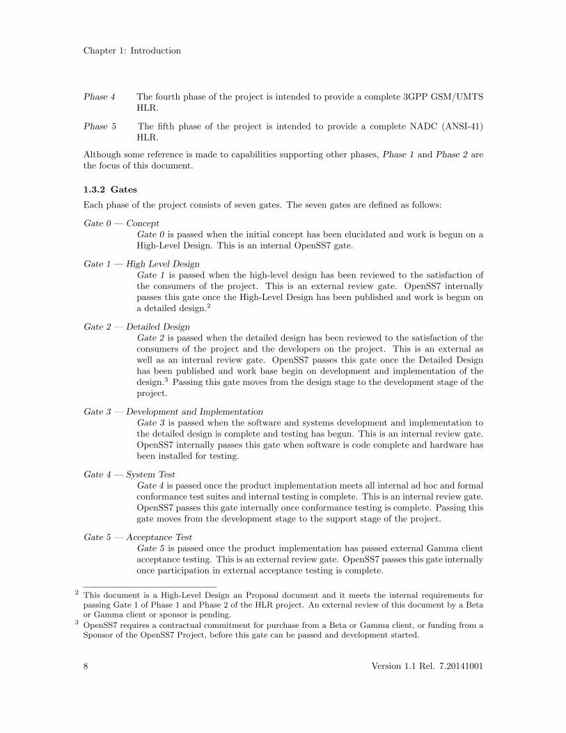
Each phase of the project consists of seven gates. The seven gates are defined as follows:
Gate 0 — ConceptGate 0 is passed when the initial concept has been elucidated and work is begun on aHigh-Level Design. This is an internal OpenSS7 gate.
Gate 1 — High Level DesignGate 1 is passed when the high-level design has been reviewed to the satisfaction ofthe consumers of the project. This is an external review gate. OpenSS7 internallypasses this gate once the High-Level Design has been published and work is begun ona detailed design.2
Gate 2 — Detailed DesignGate 2 is passed when the detailed design has been reviewed to the satisfaction of theconsumers of the project and the developers on the project. This is an external aswell as an internal review gate. OpenSS7 passes this gate once the Detailed Designhas been published and work base begin on development and implementation of thedesign.3 Passing this gate moves from the design stage to the development stage of theproject.
Gate 3 — Development and ImplementationGate 3 is passed when the software and systems development and implementation tothe detailed design is complete and testing has begun. This is an internal review gate.OpenSS7 internally passes this gate when software is code complete and hardware hasbeen installed for testing.
Gate 4 — System TestGate 4 is passed once the product implementation meets all internal ad hoc and formalconformance test suites and internal testing is complete. This is an internal review gate.OpenSS7 passes this gate internally once conformance testing is complete. Passing thisgate moves from the development stage to the support stage of the project.
Gate 5 — Acceptance TestGate 5 is passed once the product implementation has passed external Gamma clientacceptance testing. This is an external review gate. OpenSS7 passes this gate internallyonce participation in external acceptance testing is complete.
2 This document is a High-Level Design an Proposal document and it meets the internal requirements forpassing Gate 1 of Phase 1 and Phase 2 of the HLR project. An external review of this document by a Betaor Gamma client or sponsor is pending.
3 OpenSS7 requires a contractual commitment for purchase from a Beta or Gamma client, or funding from aSponsor of the OpenSS7 Project, before this gate can be passed and development started.
8 Version 1.1 Rel. 7.20141001

High Performance HLR Introduction
Gate 6 — Project CompleteGate 6 is passed once all support obligations for the product implementation have beendischarged. This is an internal review gate. OpenSS7 passes this gate once supportagreements have terminated.
For more details on Gate scheduling for Phase 1 and Phase 2 of the HLR project, see Section 9.4[Schedule], page 49.
2014-10-25 9

High Performance HLR Application Architecture
2 Application Architecture
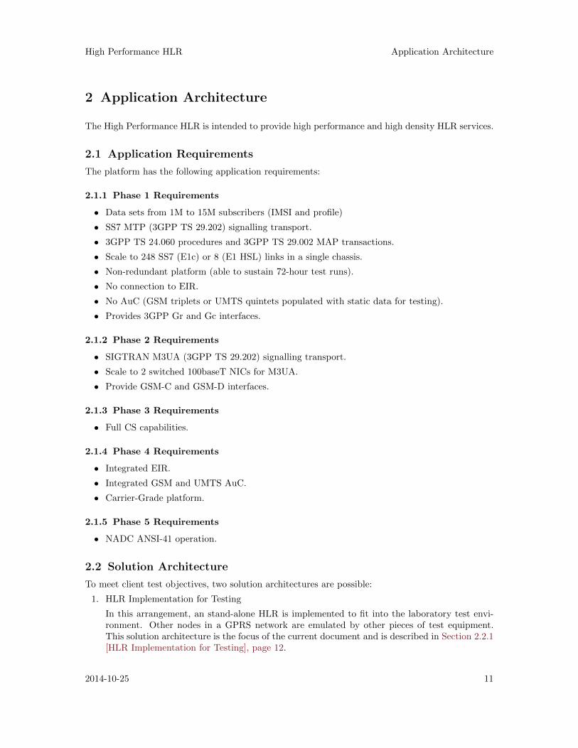
The High Performance HLR is intended to provide high performance and high density HLR services.
2.1 Application Requirements
The platform has the following application requirements:
2.1.1 Phase 1 Requirements
• Data sets from 1M to 15M subscribers (IMSI and profile)
• SS7 MTP (3GPP TS 29.202) signalling transport.
• 3GPP TS 24.060 procedures and 3GPP TS 29.002 MAP transactions.
• Scale to 248 SS7 (E1c) or 8 (E1 HSL) links in a single chassis.
• Non-redundant platform (able to sustain 72-hour test runs).
• No connection to EIR.
• No AuC (GSM triplets or UMTS quintets populated with static data for testing).
• Provides 3GPP Gr and Gc interfaces.
2.1.2 Phase 2 Requirements
• SIGTRAN M3UA (3GPP TS 29.202) signalling transport.
• Scale to 2 switched 100baseT NICs for M3UA.
• Provide GSM-C and GSM-D interfaces.
2.1.3 Phase 3 Requirements
• Full CS capabilities.
2.1.4 Phase 4 Requirements
• Integrated EIR.
• Integrated GSM and UMTS AuC.
• Carrier-Grade platform.
2.1.5 Phase 5 Requirements
• NADC ANSI-41 operation.
2.2 Solution Architecture
To meet client test objectives, two solution architectures are possible:
1. HLR Implementation for Testing
In this arrangement, an stand-alone HLR is implemented to fit into the laboratory test envi-ronment. Other nodes in a GPRS network are emulated by other pieces of test equipment.This solution architecture is the focus of the current document and is described in Section 2.2.1[HLR Implementation for Testing], page 12.
2014-10-25 11
Chapter 2: Application Architecture
2. Ferry Clip Testing
In this arrangement, the one test platform emulates all nodes in the GPRS network to performfull ferry-clip testing of the Implementation Under Test. This solution architecture wouldbe a better arrangement for systematic testing with a single test harness and is described inSection A.1.1 [Ferry Clip Testing], page 55. Development of such an arrangement is outsidethe scope of the current proposal.
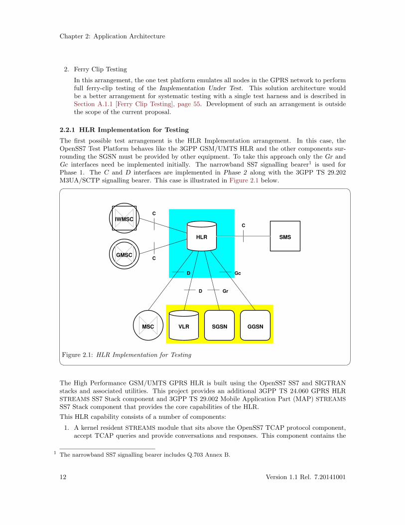
2.2.1 HLR Implementation for Testing
The first possible test arrangement is the HLR Implementation arrangement. In this case, theOpenSS7 Test Platform behaves like the 3GPP GSM/UMTS HLR and the other components sur-rounding the SGSN must be provided by other equipment. To take this approach only the Gr andGc interfaces need be implemented initially. The narrowband SS7 signalling bearer1 is used forPhase 1. The C and D interfaces are implemented in Phase 2 along with the 3GPP TS 29.202M3UA/SCTP signalling bearer. This case is illustrated in Figure 2.1 below.� �
HLR
VLR GGSN
SMS
SGSNMSC
GMSC
IWMSC
Gc
GrD
D
C
C
C
Figure 2.1: HLR Implementation for Testing The High Performance GSM/UMTS GPRS HLR is built using the OpenSS7 SS7 and SIGTRANstacks and associated utilities. This project provides an additional 3GPP TS 24.060 GPRS HLRSTREAMS SS7 Stack component and 3GPP TS 29.002 Mobile Application Part (MAP) STREAMS
SS7 Stack component that provides the core capabilities of the HLR.
This HLR capability consists of a number of components:
1. A kernel resident STREAMS module that sits above the OpenSS7 TCAP protocol component,accept TCAP queries and provide conversations and responses. This component contains the
1 The narrowband SS7 signalling bearer includes Q.703 Annex B.
12 Version 1.1 Rel. 7.20141001
High Performance HLR Application Architecture
3GPP TS 29.002 message encoder and decoders and mapping to and from the TC interface2
primitives of the TCAP component below. This module implements a new GSMMAP primitiveinterface providing 3GPP TS 29.002 defined primitives.3
2. A kernel resident STREAMS module that sits above the OpenSS7 MAP protocol component.This component exchanges 3GPP TS 29.002 MAP primitives with the module beneath andimplements the 3GPP TS 24.060 Release 4 state machines for a GPRS HLR. This module alsoprovides rule-based, template, and cached subscriber profile requests.
3. A user-space daemon that services cache miss IMSI profile requests against an external database.
4. User application programs used to configure and provision rules, templates and the externaldatabase.
The solution architecture reuses where possible OpenSS7 SS7 and SIGTRAN stack components,drivers and hardware. The solution starts as a hardened chassis non-redundant PC-based PCIplatform. A carrier grade redundant and network protection switched CompactPCI NEBS chassisis made available in Phase 3.
2 OpenSS7 implements the Q.771 TC interface with the Transaction Component Interface. See Section “In-troduction” in Transaction Component Interface Specification. See also tci(7).
3 OpenSS7 implements the 3GPP TS 29.002 MAP interface with the Mobile Application Part Interface. SeeSection “Introduction” in Mobile Application Part Interface Specification. See also mapi(8).
2014-10-25 13
Chapter 2: Application Architecture
2.3 Transaction Flows
This section provides some illustrative transaction flows.1
2.3.1 Attach Transaction Flow
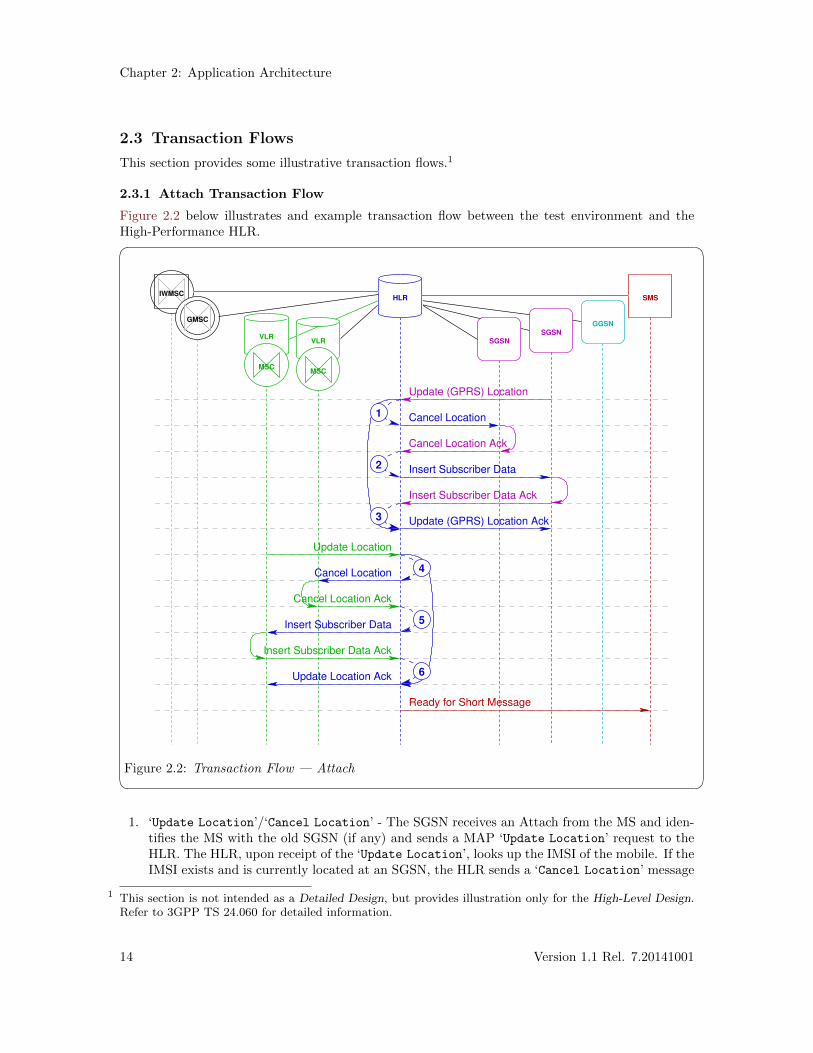
Figure 2.2 below illustrates and example transaction flow between the test environment and theHigh-Performance HLR.� �
HLR
VLRVLR
IWMSC
GMSC
SGSN
SGSN
MSCMSC
SMS
GGSN
Cancel Location
Insert Subscriber Data
Update (GPRS) Location Ack
Cancel Location
Insert Subscriber Data
Update Location Ack
Update (GPRS) Location
Cancel Location Ack
Insert Subscriber Data Ack
Update Location
Cancel Location Ack
Insert Subscriber Data Ack
Ready for Short Message
2
1
3
4
5
6
Figure 2.2: Transaction Flow — Attach 1. ‘Update Location’/‘Cancel Location’ - The SGSN receives an Attach from the MS and iden-
tifies the MS with the old SGSN (if any) and sends a MAP ‘Update Location’ request to theHLR. The HLR, upon receipt of the ‘Update Location’, looks up the IMSI of the mobile. If theIMSI exists and is currently located at an SGSN, the HLR sends a ‘Cancel Location’ message
1 This section is not intended as a Detailed Design, but provides illustration only for the High-Level Design.Refer to 3GPP TS 24.060 for detailed information.
14 Version 1.1 Rel. 7.20141001
High Performance HLR Application Architecture
to the old SGSN. If the MS is not located at an existing SGSN (first attach), step (2) is skippedand an ‘Insert Subscriber Data’ message is sent from the HLR to the updating SGSN.
The existing SGSN is determined by maintaining the SS7 point code of the SGSN at which theMS was last located and whether the MS is currently attached.
2. ‘Cancel Location Ack’/‘Insert Subscriber Data’ - Upon receiving a ‘Cancel Location Ack’from the old SGSN, the HLR sends a ‘Insert Subscriber Data’ message to the updatingSGSN.
3. ‘Insert Subscriber Data Ack’/‘Update Location Ack’ - Upon receiving a ‘InsertSubscriber Data Ack’, the HLR sends a ‘Update Location Ack’ to the updating SGSN.
4. ‘Update Location’/‘Cancel Location’ -
5. ‘Cancel Location Ack’/‘Insert Subscriber Data’ -
6. ‘Insert Subscriber Data Ack’/‘Update Location Ack’ -
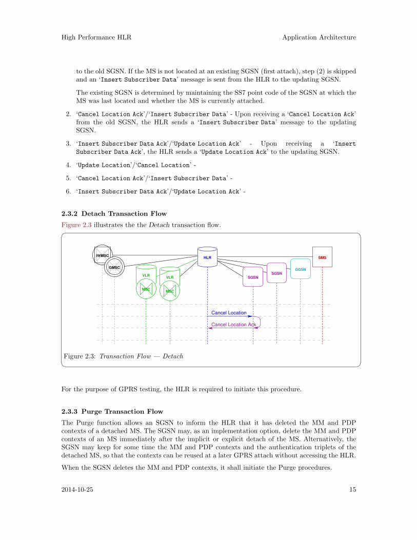
2.3.2 Detach Transaction Flow
Figure 2.3 illustrates the the Detach transaction flow.� �HLR
VLRVLR
IWMSC
GMSC
SGSN
SGSN
MSCMSC
SMS
GGSN
Cancel Location
Cancel Location Ack
Figure 2.3: Transaction Flow — Detach For the purpose of GPRS testing, the HLR is required to initiate this procedure.
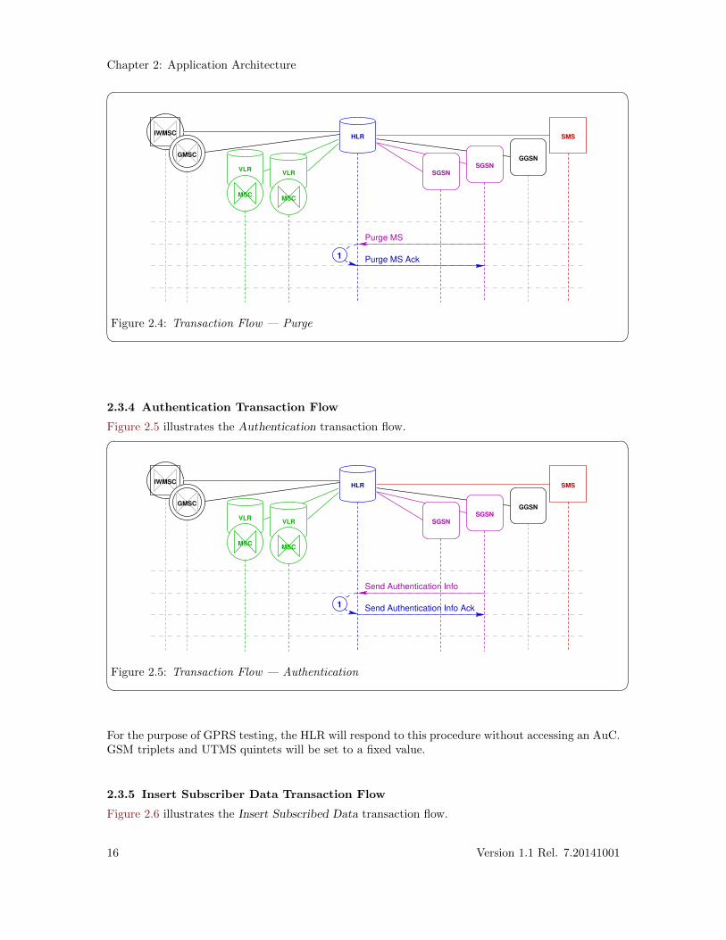
2.3.3 Purge Transaction Flow
The Purge function allows an SGSN to inform the HLR that it has deleted the MM and PDPcontexts of a detached MS. The SGSN may, as an implementation option, delete the MM and PDPcontexts of an MS immediately after the implicit or explicit detach of the MS. Alternatively, theSGSN may keep for some time the MM and PDP contexts and the authentication triplets of thedetached MS, so that the contexts can be reused at a later GPRS attach without accessing the HLR.
When the SGSN deletes the MM and PDP contexts, it shall initiate the Purge procedures.
2014-10-25 15
Chapter 2: Application Architecture
� �HLR
VLRVLR
IWMSC
GMSCGGSN
SGSN
SGSN
MSCMSC
SMS
Purge MS Ack
Purge MS
1
Figure 2.4: Transaction Flow — Purge
2.3.4 Authentication Transaction Flow
Figure 2.5 illustrates the Authentication transaction flow.� �HLR
VLRVLR
IWMSC
GMSCGGSN
SGSN
SGSN
MSCMSC
SMS
Send Authentication Info Ack
Send Authentication Info
1
Figure 2.5: Transaction Flow — Authentication For the purpose of GPRS testing, the HLR will respond to this procedure without accessing an AuC.GSM triplets and UTMS quintets will be set to a fixed value.
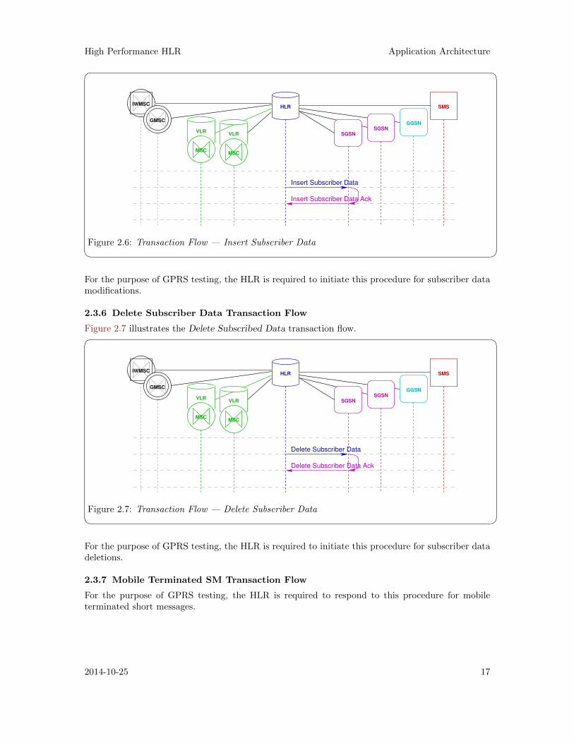
2.3.5 Insert Subscriber Data Transaction Flow
Figure 2.6 illustrates the Insert Subscribed Data transaction flow.
16 Version 1.1 Rel. 7.20141001
High Performance HLR Application Architecture
� �HLR
VLRVLR
IWMSC
GMSC
SGSN
SGSN
MSCMSC
SMS
GGSN
Insert Subscriber Data
Insert Subscriber Data Ack
Figure 2.6: Transaction Flow — Insert Subscriber Data For the purpose of GPRS testing, the HLR is required to initiate this procedure for subscriber datamodifications.
2.3.6 Delete Subscriber Data Transaction Flow
Figure 2.7 illustrates the Delete Subscribed Data transaction flow.� �HLR
VLRVLR
IWMSC
GMSC
SGSN
SGSN
MSCMSC
SMS
GGSN
Delete Subscriber Data
Delete Subscriber Data Ack
Figure 2.7: Transaction Flow — Delete Subscriber Data For the purpose of GPRS testing, the HLR is required to initiate this procedure for subscriber datadeletions.
2.3.7 Mobile Terminated SM Transaction Flow
For the purpose of GPRS testing, the HLR is required to respond to this procedure for mobileterminated short messages.
2014-10-25 17

High Performance HLR Network Architecture
3 Network Architecture
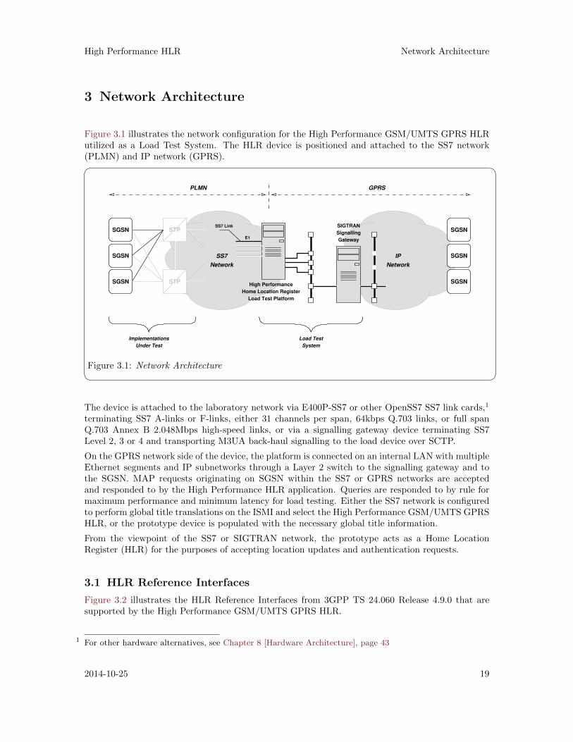
Figure 3.1 illustrates the network configuration for the High Performance GSM/UMTS GPRS HLRutilized as a Load Test System. The HLR device is positioned and attached to the SS7 network(PLMN) and IP network (GPRS).� �
SS7
Network
IP
Network
STP
STP
SGSN
SGSN
SGSNHigh Performance
Home Location Register
Load Test Platform
SIGTRAN
Signalling
Gateway
SGSN
SGSN
SGSN
E1
SS7 Link
GPRSPLMN
Implementations
Under Test
Load Test
System
Figure 3.1: Network Architecture The device is attached to the laboratory network via E400P-SS7 or other OpenSS7 SS7 link cards,1
terminating SS7 A-links or F-links, either 31 channels per span, 64kbps Q.703 links, or full spanQ.703 Annex B 2.048Mbps high-speed links, or via a signalling gateway device terminating SS7Level 2, 3 or 4 and transporting M3UA back-haul signalling to the load device over SCTP.
On the GPRS network side of the device, the platform is connected on an internal LAN with multipleEthernet segments and IP subnetworks through a Layer 2 switch to the signalling gateway and tothe SGSN. MAP requests originating on SGSN within the SS7 or GPRS networks are acceptedand responded to by the High Performance HLR application. Queries are responded to by rule formaximum performance and minimum latency for load testing. Either the SS7 network is configuredto perform global title translations on the ISMI and select the High Performance GSM/UMTS GPRSHLR, or the prototype device is populated with the necessary global title information.
From the viewpoint of the SS7 or SIGTRAN network, the prototype acts as a Home LocationRegister (HLR) for the purposes of accepting location updates and authentication requests.
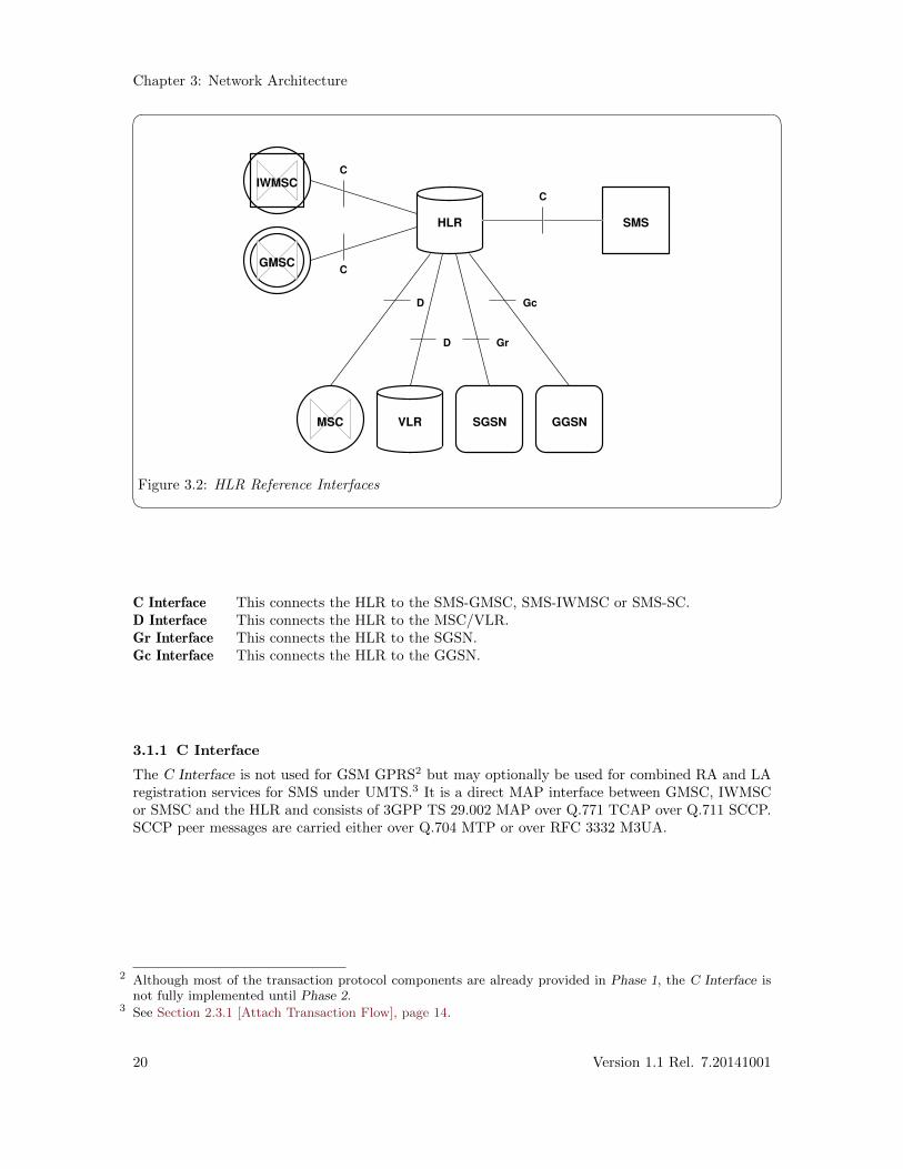
3.1 HLR Reference Interfaces
Figure 3.2 illustrates the HLR Reference Interfaces from 3GPP TS 24.060 Release 4.9.0 that aresupported by the High Performance GSM/UMTS GPRS HLR.
1 For other hardware alternatives, see Chapter 8 [Hardware Architecture], page 43
2014-10-25 19
Chapter 3: Network Architecture
� �
HLR
VLR GGSN
SMS
SGSNMSC
GMSC
IWMSC
Gc
GrD
D
C
C
C
Figure 3.2: HLR Reference Interfaces
C Interface This connects the HLR to the SMS-GMSC, SMS-IWMSC or SMS-SC.D Interface This connects the HLR to the MSC/VLR.Gr Interface This connects the HLR to the SGSN.Gc Interface This connects the HLR to the GGSN.
3.1.1 C Interface
The C Interface is not used for GSM GPRS2 but may optionally be used for combined RA and LAregistration services for SMS under UMTS.3 It is a direct MAP interface between GMSC, IWMSCor SMSC and the HLR and consists of 3GPP TS 29.002 MAP over Q.771 TCAP over Q.711 SCCP.SCCP peer messages are carried either over Q.704 MTP or over RFC 3332 M3UA.
2 Although most of the transaction protocol components are already provided in Phase 1, the C Interface isnot fully implemented until Phase 2.
3 See Section 2.3.1 [Attach Transaction Flow], page 14.
20 Version 1.1 Rel. 7.20141001
High Performance HLR Network Architecture
� �MAP
TCAP
SCCP
Signalling
Bearer
MAP
TCAP
SCCP
Signalling
Bearer
SMS−GMSC/IWMSC HLRC
TS 29.002
TS 29.202 TS 29.202
TS 29.002
Network Specific
Network Specific
Network Specific
Network Specific
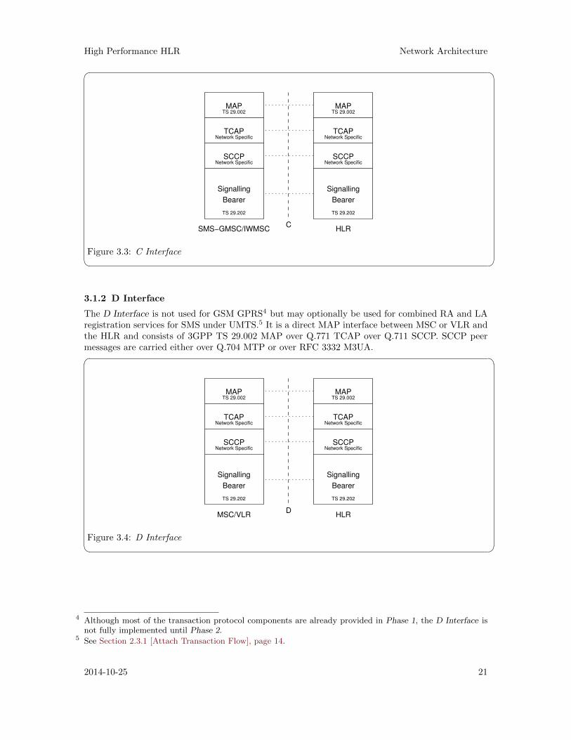
Figure 3.3: C Interface 3.1.2 D Interface
The D Interface is not used for GSM GPRS4 but may optionally be used for combined RA and LAregistration services for SMS under UMTS.5 It is a direct MAP interface between MSC or VLR andthe HLR and consists of 3GPP TS 29.002 MAP over Q.771 TCAP over Q.711 SCCP. SCCP peermessages are carried either over Q.704 MTP or over RFC 3332 M3UA.� �
MAP
TCAP
SCCP
Signalling
Bearer
MAP
TCAP
SCCP
Signalling
Bearer
HLRD
MSC/VLR
TS 29.002
TS 29.202
TS 29.002
TS 29.202
Network Specific Network Specific
Network SpecificNetwork Specific
Figure 3.4: D Interface
4 Although most of the transaction protocol components are already provided in Phase 1, the D Interface isnot fully implemented until Phase 2.
5 See Section 2.3.1 [Attach Transaction Flow], page 14.
2014-10-25 21
Chapter 3: Network Architecture
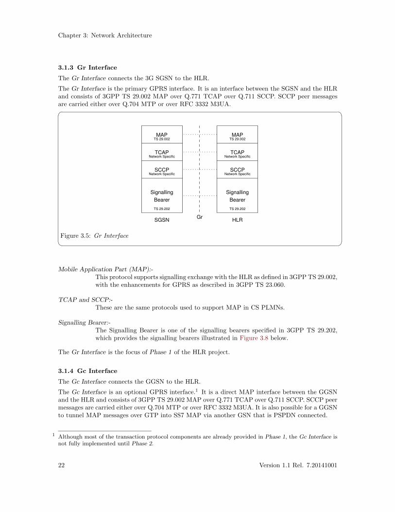
3.1.3 Gr Interface
The Gr Interface connects the 3G SGSN to the HLR.
The Gr Interface is the primary GPRS interface. It is an interface between the SGSN and the HLRand consists of 3GPP TS 29.002 MAP over Q.771 TCAP over Q.711 SCCP. SCCP peer messagesare carried either over Q.704 MTP or over RFC 3332 M3UA.� �
MAP
TCAP
SCCP
Signalling
Bearer
MAP
TCAP
SCCP
Signalling
Bearer
HLRSGSNGr
TS 29.002
TS 29.202
TS 29.002
TS 29.202
Network Specific Network Specific
Network SpecificNetwork Specific
Figure 3.5: Gr Interface Mobile Application Part (MAP):-
This protocol supports signalling exchange with the HLR as defined in 3GPP TS 29.002,with the enhancements for GPRS as described in 3GPP TS 23.060.
TCAP and SCCP:-These are the same protocols used to support MAP in CS PLMNs.
Signalling Bearer:-The Signalling Bearer is one of the signalling bearers specified in 3GPP TS 29.202,which provides the signalling bearers illustrated in Figure 3.8 below.
The Gr Interface is the focus of Phase 1 of the HLR project.
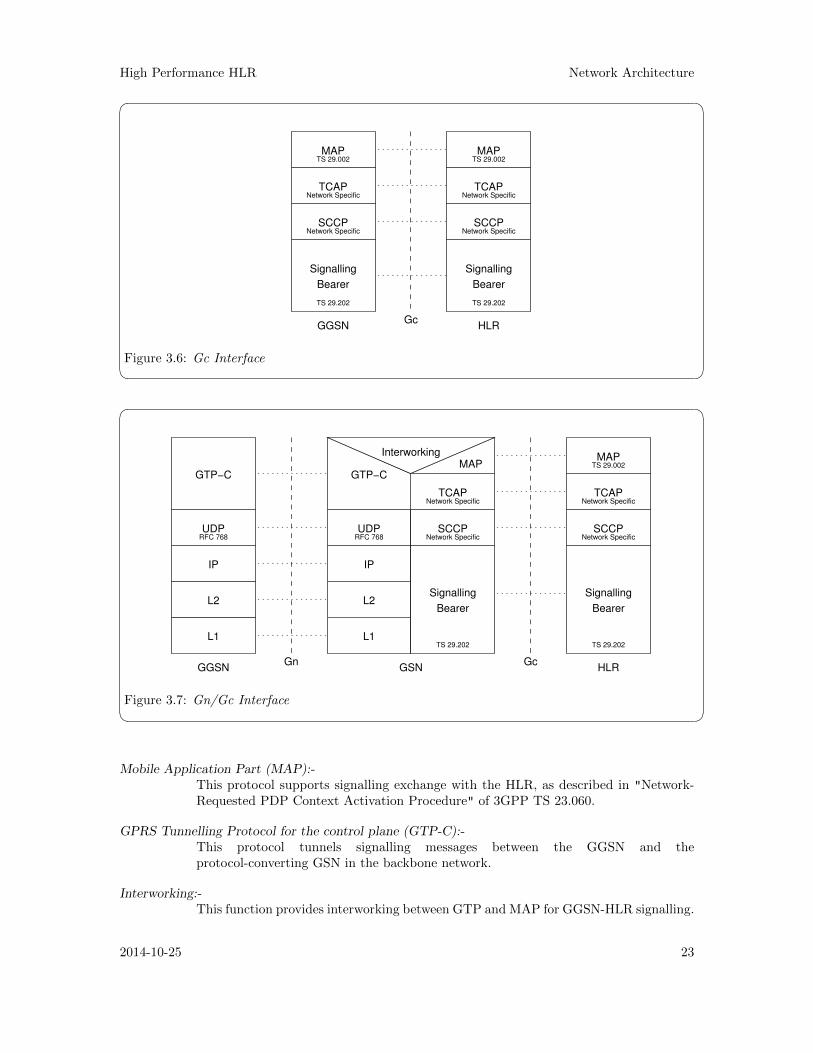
3.1.4 Gc Interface
The Gc Interface connects the GGSN to the HLR.
The Gc Interface is an optional GPRS interface.1 It is a direct MAP interface between the GGSNand the HLR and consists of 3GPP TS 29.002 MAP over Q.771 TCAP over Q.711 SCCP. SCCP peermessages are carried either over Q.704 MTP or over RFC 3332 M3UA. It is also possible for a GGSNto tunnel MAP messages over GTP into SS7 MAP via another GSN that is PSPDN connected.
1 Although most of the transaction protocol components are already provided in Phase 1, the Gc Interface isnot fully implemented until Phase 2.
22 Version 1.1 Rel. 7.20141001
High Performance HLR Network Architecture
� �MAP
TCAP
SCCP
Signalling
Bearer
MAP
TCAP
SCCP
Signalling
Bearer
HLRGGSNGc
TS 29.202TS 29.202
TS 29.002 TS 29.002
Network Specific
Network Specific Network Specific
Network Specific
Figure 3.6: Gc Interface � �
GTP−C
UDP
IP
L2
L1
Signalling
Bearer
TCAP
SCCP
MAP
Signalling
Bearer
UDP
IP
L2
L1
Gn
GTP−C
SCCP
TCAP
MAPInterworking
GcHLRGSNGGSN
TS 29.002
TS 29.202TS 29.202
RFC 768 RFC 768
Network Specific
Network Specific Network Specific
Network Specific
Figure 3.7: Gn/Gc Interface Mobile Application Part (MAP):-
This protocol supports signalling exchange with the HLR, as described in "Network-Requested PDP Context Activation Procedure" of 3GPP TS 23.060.
GPRS Tunnelling Protocol for the control plane (GTP-C):-This protocol tunnels signalling messages between the GGSN and theprotocol-converting GSN in the backbone network.
Interworking:-This function provides interworking between GTP and MAP for GGSN-HLR signalling.
2014-10-25 23
Chapter 3: Network Architecture
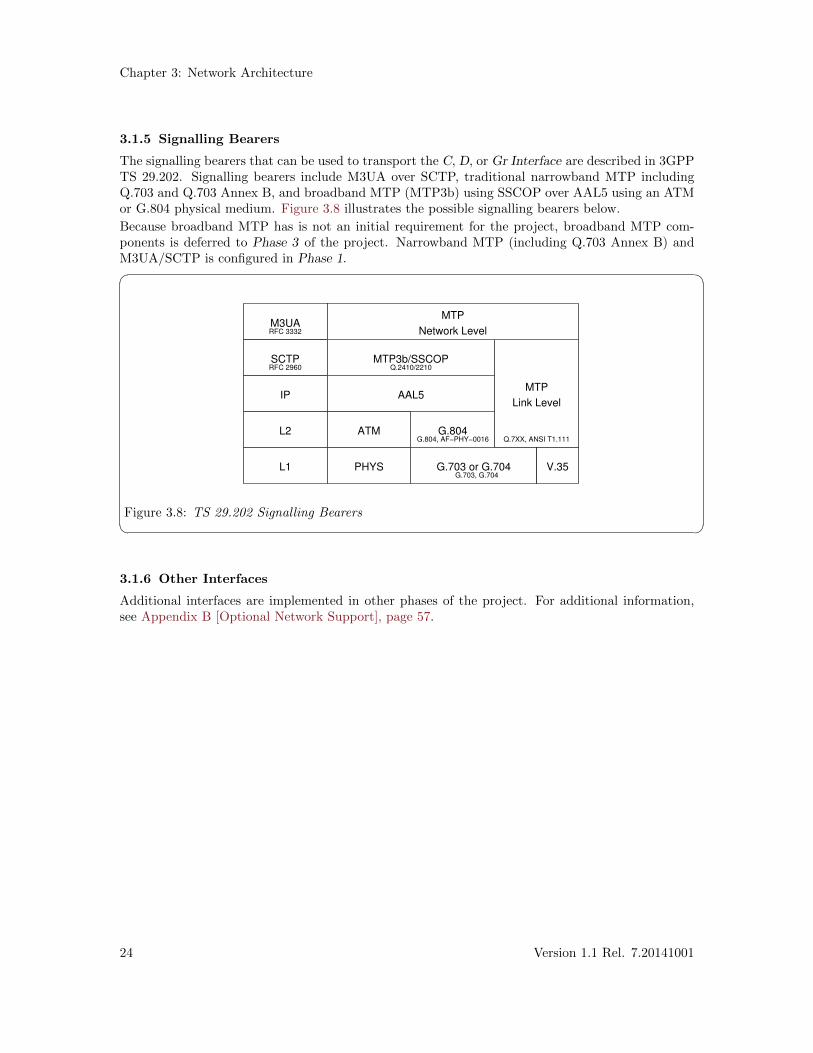
3.1.5 Signalling Bearers
The signalling bearers that can be used to transport the C, D, or Gr Interface are described in 3GPPTS 29.202. Signalling bearers include M3UA over SCTP, traditional narrowband MTP includingQ.703 and Q.703 Annex B, and broadband MTP (MTP3b) using SSCOP over AAL5 using an ATMor G.804 physical medium. Figure 3.8 illustrates the possible signalling bearers below.
Because broadband MTP has is not an initial requirement for the project, broadband MTP com-ponents is deferred to Phase 3 of the project. Narrowband MTP (including Q.703 Annex B) andM3UA/SCTP is configured in Phase 1.� �
RFC 2960
RFC 3332
Q.2410/2210
Q.7XX, ANSI T1.111G.804, AF−PHY−0016
G.703, G.704
M3UA
SCTP
IP
L2
L1
MTP
Network Level
Link Level
MTP
V.35G.703 or G.704
G.804
AAL5
MTP3b/SSCOP
ATM
PHYS
Figure 3.8: TS 29.202 Signalling Bearers 3.1.6 Other Interfaces
Additional interfaces are implemented in other phases of the project. For additional information,see Appendix B [Optional Network Support], page 57.
24 Version 1.1 Rel. 7.20141001
High Performance HLR System Architecture
4 System Architecture
This section details the solution system architecture. The solution system architecture consists ofthe computing platform and its placement within the locale installation environment.
The solution system has the following requirements:
— 19" rack.
— 110 VAC electrical power.
— Commercial cooling.
— Bantam to RJ-48c patch panel.
2014-10-25 25

High Performance HLR Platform Architecture
5 Platform Architecture
This section details the platform architecture. The solution platform architecture consists of thecomputing platform and associated hardware, interfaces and peripherals.
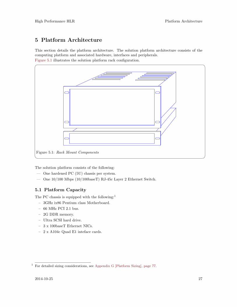
Figure 5.1 illustrates the solution platform rack configuration.� �
Figure 5.1: Rack Mount Components The solution platform consists of the following:
— One hardened PC (5U) chassis per system.
— One 10/100 Mbps (10/100baseT) RJ-45c Layer 2 Ethernet Switch.
5.1 Platform Capacity
The PC chassis is equipped with the following:1
– 3GHz ix86 Pentium class Motherboard.
– 66 MHz PCI 2.1 bus.
– 2G DDR memory.
– Ultra SCSI hard drive.
– 3 x 100baseT Ethernet NICs.
– 2 x A104c Quad E1 inteface cards.
1 For detailed sizing considerations, see Appendix G [Platform Sizing], page 77.
2014-10-25 27

High Performance HLR Protocol Architecture
6 Protocol Architecture
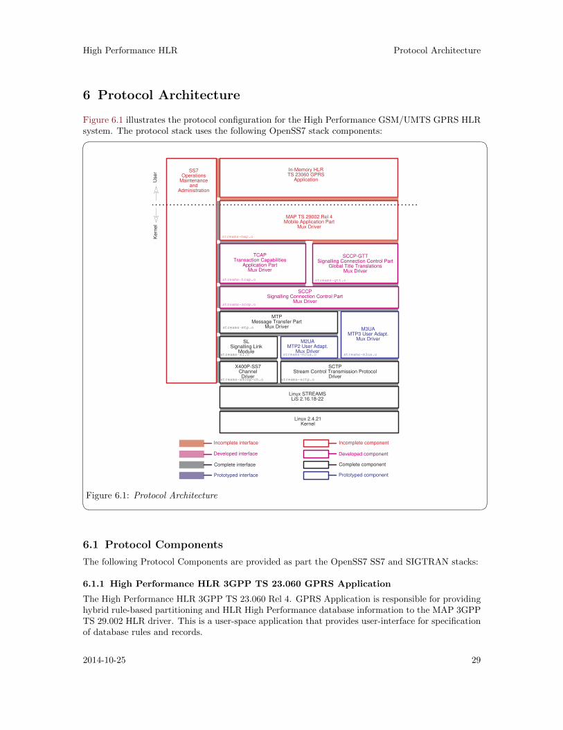
Figure 6.1 illustrates the protocol configuration for the High Performance GSM/UMTS GPRS HLRsystem. The protocol stack uses the following OpenSS7 stack components:� �
Linux 2.4.21Kernel
Linux STREAMSLiS 2.16.18-22
X400P-SS7ChannelDriver
SLSignalling Link
Module
MTPMessage Transfer Part
Mux Driver
TCAPTransaction Capabilities
Application PartMux Driver
SS7Operations
Maintenanceand
Administration
User
Kern
el
SCCPSignalling Connection Control Part
Mux Driver
SCTPStream Control Transmission Protocol
Driver
M2UAMTP2 User Adapt.
Mux Driver
M3UAMTP3 User Adapt.
Mux Driver
In-Memory HLRTS 23060 GPRS
Application
streams-tcap.o
streams-mtp.o
streams-sccp.o
streams-m3ua.ostreams-m2ua.ostreams-sl.o
streams-x400p-ch.o streams-sctp.o
Incomplete interface Incomplete component
Developed interface Developed component
Complete interface Complete component
Prototyped interface Prototyped component
MAP TS 29002 Rel 4Mobile Application Part
Mux Driver
streams-map.o
SCCP-GTTSignalling Connection Control Part
Global Title TranslationsMux Driver
streams-gtt.o
Figure 6.1: Protocol Architecture 6.1 Protocol Components
The following Protocol Components are provided as part the OpenSS7 SS7 and SIGTRAN stacks:
6.1.1 High Performance HLR 3GPP TS 23.060 GPRS Application
The High Performance HLR 3GPP TS 23.060 Rel 4. GPRS Application is responsible for providinghybrid rule-based partitioning and HLR High Performance database information to the MAP 3GPPTS 29.002 HLR driver. This is a user-space application that provides user-interface for specificationof database rules and records.
2014-10-25 29
Chapter 6: Protocol Architecture
The High Performance GSM/UMTS GPRS HLR Application is made up from a User-space applica-tion combined with the OpenSS7 SS7 and SIGTRAN stacks. The High Performance GSM/UMTSGPRS HLR application communicates only with the top of the SS7 stack, that is, the MAP andSCCP-GTT modules.
The High Performance GSM/UMTS GPRS HLR Application is responsible for providing data con-figuration instructions to the MAP and GTT modules. MAP and GTT modules accept both rulebased and indexed record entries for responding to transactions and translations; any transaction ortranslation which neither matches a rule nor matches an indexed entry results in a transaction ortranslation indication to the attached High Performance GSM/UMTS GPRS HLR Application.
This protocol component is developed as part of Phase 1 of this project.
6.1.2 High Performance HLR 3GPP TS 29.002 Mobile Application Part Application
The High Performance HLR 3GPP TS 29.002 Mobile Application Part Application is responsible foraccepting location update and authentication requests from the back end AC gateway and turningthose requests into GSM MAP queries to an Authentication centre and propagating the response.This is a straightforward application that converts between ONC RPC queries and responses andGSM MAP TCAP queues and responses using the published Transaction Component Interface(TCI).
The Mobile Application Part (MAP) Home Location Register (HLR) module is responsible forresponding to MAP-HLR transactions originating from the TCAP module beneath (e.g. MapLoca-tionUpdate) and is responsible for generating outgoing MAP-HLR transactions to the TCAP modulebeneath (e.g. MapInsertSubscriber). To perform its function, the MAP-HLR indexes all informationbased on the IMSI of the MS, including dynamic (state) and provisioned (subscriber) information.For performance in both a testing and production environment, the module provides three levels ofdatabase partitioning and caching:
Rules Rules can be provided that is used to determine provisioned information based oncomponents of the index (IMSI). These rules can be used to generate a rather largesimulated database without maintaining or accessing large database record areas. Therule base provides a simulated partitioned database. Each rule refers to a template orpartial template of provisioned data.
Templates Templates can be provided that specify a profile of provisioned information for a classof indexes (IMSI). Templates provide a compact local in-kernel cache of templates.Indexes reference templates rather than complete records.
Records Records can be provided that specify the provisioned information for the specific index(IMSI). Records provide a local in-kernel cache of specified records. Records are uniquefor each index.
TransactionsThe application can be queried by indicating the index IMSI and the module awaitsa response containing the provisioned information. Transactions provide access to anexternal database.
This protocol component is developed as part of Phase 1 of this project.
6.1.3 SS7 Stack Manager
The SS7 stack manager is responsible for configuration of the SS7 stack, maintenance, statisticscollection, operational measurements, management events and controls, log and alarm generation.This is daemon process that is typically customized to meet a specific application.
30 Version 1.1 Rel. 7.20141001
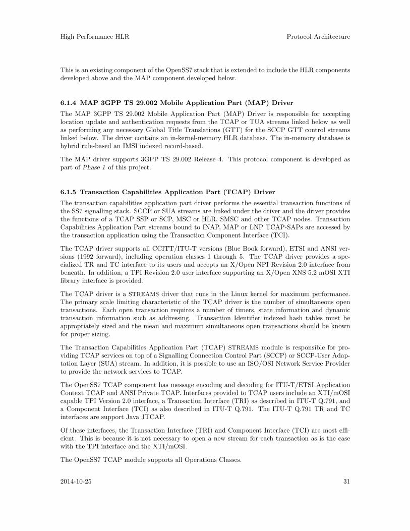
High Performance HLR Protocol Architecture
This is an existing component of the OpenSS7 stack that is extended to include the HLR componentsdeveloped above and the MAP component developed below.
6.1.4 MAP 3GPP TS 29.002 Mobile Application Part (MAP) Driver
The MAP 3GPP TS 29.002 Mobile Application Part (MAP) Driver is responsible for acceptinglocation update and authentication requests from the TCAP or TUA streams linked below as wellas performing any necessary Global Title Translations (GTT) for the SCCP GTT control streamslinked below. The driver contains an in-kernel-memory HLR database. The in-memory database ishybrid rule-based an IMSI indexed record-based.
The MAP driver supports 3GPP TS 29.002 Release 4. This protocol component is developed aspart of Phase 1 of this project.
6.1.5 Transaction Capabilities Application Part (TCAP) Driver
The transaction capabilities application part driver performs the essential transaction functions ofthe SS7 signalling stack. SCCP or SUA streams are linked under the driver and the driver providesthe functions of a TCAP SSP or SCP, MSC or HLR, SMSC and other TCAP nodes. TransactionCapabilities Application Part streams bound to INAP, MAP or LNP TCAP-SAPs are accessed bythe transaction application using the Transaction Component Interface (TCI).
The TCAP driver supports all CCITT/ITU-T versions (Blue Book forward), ETSI and ANSI ver-sions (1992 forward), including operation classes 1 through 5. The TCAP driver provides a spe-cialized TR and TC interface to its users and accepts an X/Open NPI Revision 2.0 interface frombeneath. In addition, a TPI Revision 2.0 user interface supporting an X/Open XNS 5.2 mOSI XTIlibrary interface is provided.
The TCAP driver is a STREAMS driver that runs in the Linux kernel for maximum performance.The primary scale limiting characteristic of the TCAP driver is the number of simultaneous opentransactions. Each open transaction requires a number of timers, state information and dynamictransaction information such as addressing. Transaction Identifier indexed hash tables must beappropriately sized and the mean and maximum simultaneous open transactions should be knownfor proper sizing.
The Transaction Capabilities Application Part (TCAP) STREAMS module is responsible for pro-viding TCAP services on top of a Signalling Connection Control Part (SCCP) or SCCP-User Adap-tation Layer (SUA) stream. In addition, it is possible to use an ISO/OSI Network Service Providerto provide the network services to TCAP.
The OpenSS7 TCAP component has message encoding and decoding for ITU-T/ETSI ApplicationContext TCAP and ANSI Private TCAP. Interfaces provided to TCAP users include an XTI/mOSIcapable TPI Version 2.0 interface, a Transaction Interface (TRI) as described in ITU-T Q.791, anda Component Interface (TCI) as also described in ITU-T Q.791. The ITU-T Q.791 TR and TCinterfaces are support Java JTCAP.
Of these interfaces, the Transaction Interface (TRI) and Component Interface (TCI) are most effi-cient. This is because it is not necessary to open a new stream for each transaction as is the casewith the TPI interface and the XTI/mOSI.
The OpenSS7 TCAP module supports all Operations Classes.
2014-10-25 31
Chapter 6: Protocol Architecture
� �STREAMHead
STREAMHead
isup(ISDN User Part)
Module
<RPC,CIC-Range> <RPC,CIC-Range>
sccp(Signalling Connection Control Part)
Module
tcap(Transaction Capabilities Application Part)
Module
<Application-Part> <Application Part>
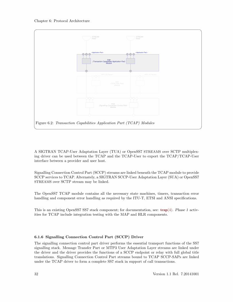
Figure 6.2: Transaction Capabilities Application Part (TCAP) Modules
A SIGTRAN TCAP-User Adaptation Layer (TUA) or OpenSS7 STREAMS over SCTP multiplex-ing driver can be used between the TCAP and the TCAP-User to export the TCAP/TCAP-Userinterface between a provider and user host.
Signalling Connection Control Part (SCCP) streams are linked beneath the TCAP module to provideSCCP services to TCAP. Alternately, a SIGTRAN SCCP-User Adaptation Layer (SUA) or OpenSS7STREAMS over SCTP stream may be linked.
The OpenSS7 TCAP module contains all the necessary state machines, timers, transaction errorhandling and component error handling as required by the ITU-T, ETSI and ANSI specifications.
This is an existing OpenSS7 SS7 stack component; for documentation, see: tcap(4). Phase 1 activ-ities for TCAP include integration testing with the MAP and HLR components.
6.1.6 Signalling Connection Control Part (SCCP) Driver
The signalling connection control part driver performs the essential transport functions of the SS7signalling stack. Message Transfer Part or MTP3 User Adaptation Layer streams are linked underthe driver and the driver provides the functions of a SCCP endpoint or relay with full global titletranslations. Signalling Connection Control Part streams bound to TCAP SCCP-SAPs are linkedunder the TCAP driver to form a complete SS7 stack in support of call transactions.
32 Version 1.1 Rel. 7.20141001
High Performance HLR Protocol Architecture
� �
sccp(Signalling Connection Control Part)
Module
SCCP SCCPISUP ISUP
isup(ISDN User Part)
Module
<RPC,CIC-Range> <RPC,CIC-Range>
tcap(Transaction Capabilities Application Part)
Module
<Application-Part> <Application Part>
mtp(Message Transfer Part)
Module
<PC,MTP-User> <PC,MTP-User>
<LPC,APC> <LPC,APC> <LPC,APC>
Per-muxSS7 Leve 3 (MTP)State Machine
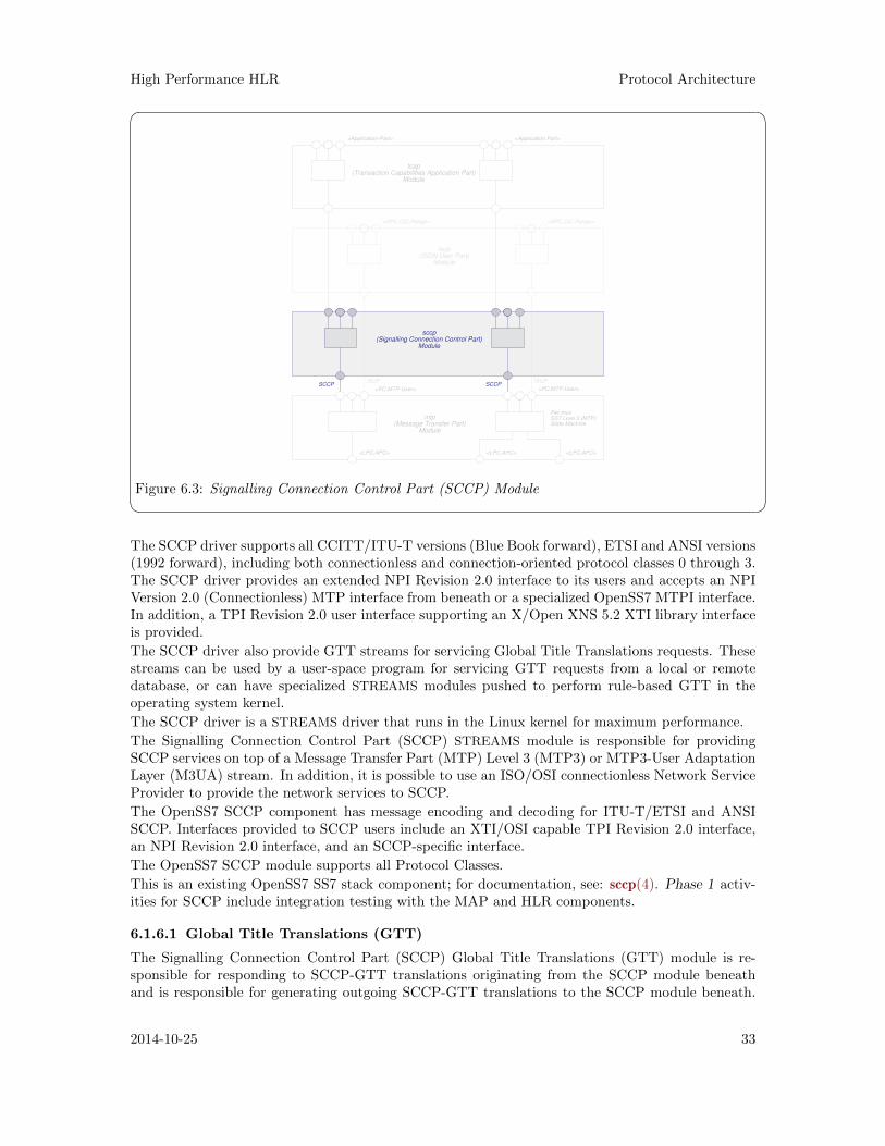
Figure 6.3: Signalling Connection Control Part (SCCP) Module The SCCP driver supports all CCITT/ITU-T versions (Blue Book forward), ETSI and ANSI versions(1992 forward), including both connectionless and connection-oriented protocol classes 0 through 3.The SCCP driver provides an extended NPI Revision 2.0 interface to its users and accepts an NPIVersion 2.0 (Connectionless) MTP interface from beneath or a specialized OpenSS7 MTPI interface.In addition, a TPI Revision 2.0 user interface supporting an X/Open XNS 5.2 XTI library interfaceis provided.
The SCCP driver also provide GTT streams for servicing Global Title Translations requests. Thesestreams can be used by a user-space program for servicing GTT requests from a local or remotedatabase, or can have specialized STREAMS modules pushed to perform rule-based GTT in theoperating system kernel.
The SCCP driver is a STREAMS driver that runs in the Linux kernel for maximum performance.
The Signalling Connection Control Part (SCCP) STREAMS module is responsible for providingSCCP services on top of a Message Transfer Part (MTP) Level 3 (MTP3) or MTP3-User AdaptationLayer (M3UA) stream. In addition, it is possible to use an ISO/OSI connectionless Network ServiceProvider to provide the network services to SCCP.
The OpenSS7 SCCP component has message encoding and decoding for ITU-T/ETSI and ANSISCCP. Interfaces provided to SCCP users include an XTI/OSI capable TPI Revision 2.0 interface,an NPI Revision 2.0 interface, and an SCCP-specific interface.
The OpenSS7 SCCP module supports all Protocol Classes.
This is an existing OpenSS7 SS7 stack component; for documentation, see: sccp(4). Phase 1 activ-ities for SCCP include integration testing with the MAP and HLR components.
6.1.6.1 Global Title Translations (GTT)
The Signalling Connection Control Part (SCCP) Global Title Translations (GTT) module is re-sponsible for responding to SCCP-GTT translations originating from the SCCP module beneathand is responsible for generating outgoing SCCP-GTT translations to the SCCP module beneath.
2014-10-25 33
Chapter 6: Protocol Architecture
To perform its function, the SCCP-GTT indexes all information based on the SCCP Address, in-cluding dynamic (state) and provisioned (result) information. For performance in both a testingand production environment, the module provides three levels of database partitioning and caching:
Rules Rules can be provided that are used to determine provisioned information based oncomponents of the index (GT). These rules can be used to generate a rather largesimulated database without maintaining or accessing large database record areas. Therule base provides a simulated partitioned database. Each rule refers to a template orpartial template of provisioned data.
Templates Templates can be provided that specify a profile of provisioned information for a class ofindexes (GT). Templates provide a compact local in-kernel cache of templates. Indexesreference templates rather than complete records.
Records Records can be provided that specify the provisioned information for the specific index(GT). Records provide a local in-kernel cache of specified records. Records are uniquefor each index.
TranslationsThe application can be queried by indicating the index (GT) and the module awaitsa response containing the provisioned information. Translations provide access to anexternal database or algorithm.
For the High Performance GSM/UMTS GPRS HLR application, messages can berouted on Translation Type or on the basis of the Subsystem Number alone, resultingin a simple rule provided to the SCCP-GTT. If the High Performance GSM/UMTSGPRS HLR application is not expected to perform in any other role, the High Perfor-mance GSM/UMTS GPRS HLR application can bind as the "Default Destination" forall SCCP Unitdata messages, obviating the need for GTT.
This is an existing OpenSS7 SS7 stack component; for documentation, see: sccp(4). Phase 1 activ-ities for SCCP include integration testing with the MAP and HLR components.
6.1.7 Message Transfer Part (MTP) Driver
The message transfer part driver performs the essential network functions of the SS7 signalling stack.M2UA streams (see below) may be linked under the driver and the driver provides the functions ofa Signalling End Point (SEP) or Signalling Transfer Point (STP).1
1 Message Transfer Part streams bound to ISUP MTP-SAPs are linked under the ISUP driver above to form acomplete SS7 stack in support of call switching. Message Transfer Part streams bound to SCCP MTP-SAPsare linked under the SCCP driver above to form a complete SS7 stack in support of transaction services.
34 Version 1.1 Rel. 7.20141001
High Performance HLR Protocol Architecture
� �
sccp(Signalling Connection Control Part)
Module
SCCP SCCP
Per-muxSS7 Link Set
State Machine
SLSI
Signalling Link SetModule
SLSI SLSI
Message Transfer PartModule
<PC,MTP-User> <PC,MTP-User>
<LPC,APC> <LPC,APC> <LPC,APC>
<LPC,APC,SLC>
Per-muxSS7 Leve 3 (MTP)State Machine
isup(ISDN User Part)
Module
<RPC,CIC-Range> <RPC,CIC-Range>
MTPI MTPI
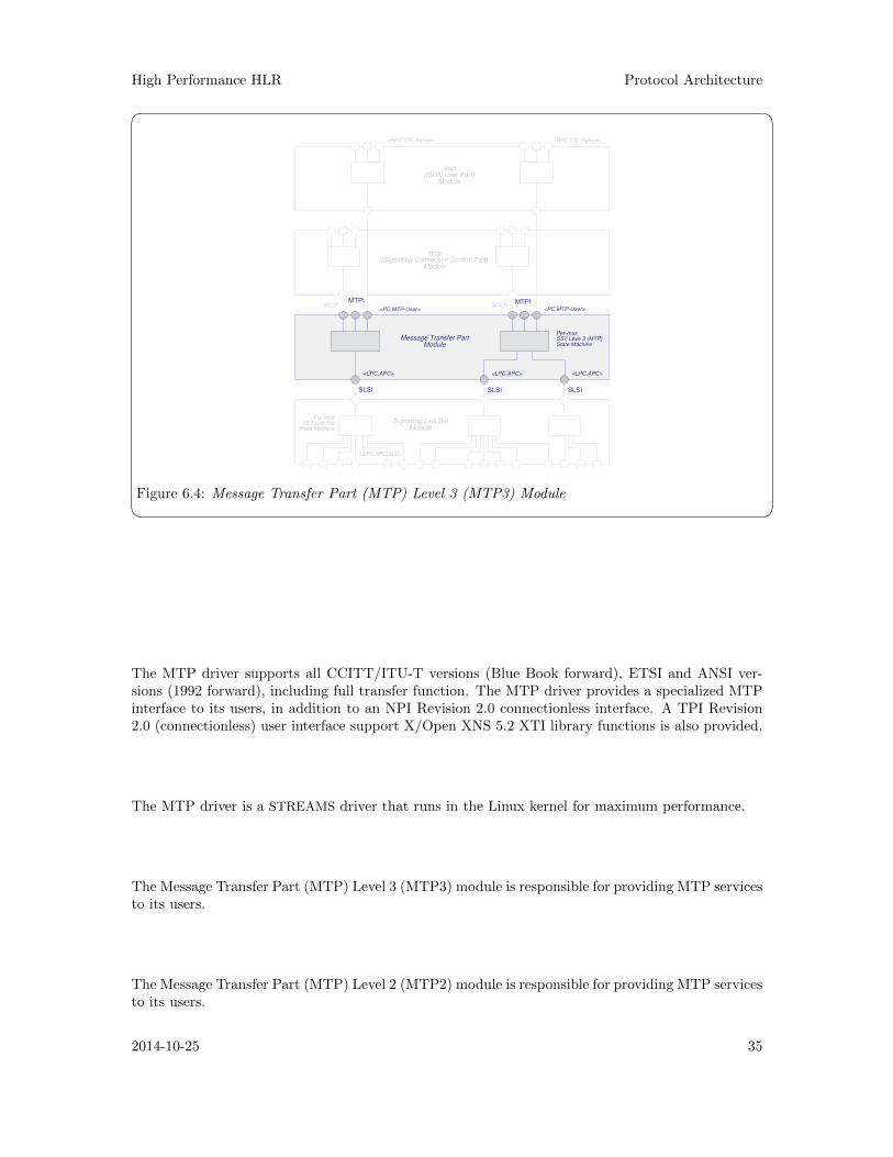
Figure 6.4: Message Transfer Part (MTP) Level 3 (MTP3) Module
The MTP driver supports all CCITT/ITU-T versions (Blue Book forward), ETSI and ANSI ver-sions (1992 forward), including full transfer function. The MTP driver provides a specialized MTPinterface to its users, in addition to an NPI Revision 2.0 connectionless interface. A TPI Revision2.0 (connectionless) user interface support X/Open XNS 5.2 XTI library functions is also provided.
The MTP driver is a STREAMS driver that runs in the Linux kernel for maximum performance.
The Message Transfer Part (MTP) Level 3 (MTP3) module is responsible for providing MTP servicesto its users.
The Message Transfer Part (MTP) Level 2 (MTP2) module is responsible for providing MTP servicesto its users.
2014-10-25 35
Chapter 6: Protocol Architecture
� �
Per-streamSS7 Level 2State Machine
Signalling LinkModule
<PPA>
SLI SLI SLI SLI
Per-muxSS7 Link Set
State Machine
SLSI
Signalling Link SetModule
SLSI SLSI
Message Transfer PartModule
<PC,MTP-User> <PC,MTP-User>
<LPC,APC> <LPC,APC> <LPC,APC>
<LPC,APC,SLC>
Per-muxSS7 Leve 3 (MTP)State Machine
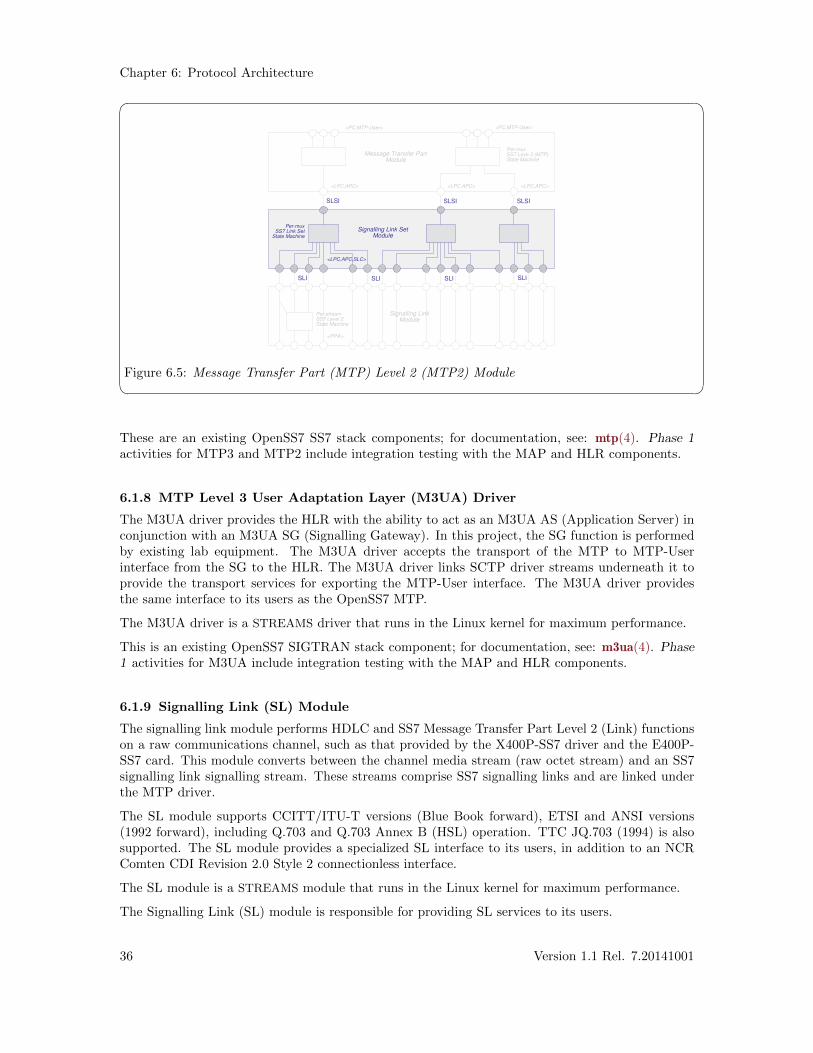
Figure 6.5: Message Transfer Part (MTP) Level 2 (MTP2) Module These are an existing OpenSS7 SS7 stack components; for documentation, see: mtp(4). Phase 1activities for MTP3 and MTP2 include integration testing with the MAP and HLR components.
6.1.8 MTP Level 3 User Adaptation Layer (M3UA) Driver
The M3UA driver provides the HLR with the ability to act as an M3UA AS (Application Server) inconjunction with an M3UA SG (Signalling Gateway). In this project, the SG function is performedby existing lab equipment. The M3UA driver accepts the transport of the MTP to MTP-Userinterface from the SG to the HLR. The M3UA driver links SCTP driver streams underneath it toprovide the transport services for exporting the MTP-User interface. The M3UA driver providesthe same interface to its users as the OpenSS7 MTP.
The M3UA driver is a STREAMS driver that runs in the Linux kernel for maximum performance.
This is an existing OpenSS7 SIGTRAN stack component; for documentation, see: m3ua(4). Phase1 activities for M3UA include integration testing with the MAP and HLR components.
6.1.9 Signalling Link (SL) Module
The signalling link module performs HDLC and SS7 Message Transfer Part Level 2 (Link) functionson a raw communications channel, such as that provided by the X400P-SS7 driver and the E400P-SS7 card. This module converts between the channel media stream (raw octet stream) and an SS7signalling link signalling stream. These streams comprise SS7 signalling links and are linked underthe MTP driver.
The SL module supports CCITT/ITU-T versions (Blue Book forward), ETSI and ANSI versions(1992 forward), including Q.703 and Q.703 Annex B (HSL) operation. TTC JQ.703 (1994) is alsosupported. The SL module provides a specialized SL interface to its users, in addition to an NCRComten CDI Revision 2.0 Style 2 connectionless interface.
The SL module is a STREAMS module that runs in the Linux kernel for maximum performance.
The Signalling Link (SL) module is responsible for providing SL services to its users.
36 Version 1.1 Rel. 7.20141001
High Performance HLR Protocol Architecture
� �
SignallingData Terminals(Interface cards)
SignallingData Terminals(Interface cards)
SignallingData Terminals(Interface cards)
SignallingData Terminals(Interface cards)
Driver Driver Driver Driver
SDTI SDTI SDTI SDTI
Per-streamSS7 Level 2State Machine
SLI SLI SLII SLI
Signalling LinkModule
Per-muxSS7 Level LinkState Machine
SLSI
Signalling LinkModule
SLSI SLSI
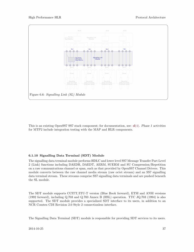
Figure 6.6: Signalling Link (SL) Module
This is an existing OpenSS7 SS7 stack component; for documentation, see: sl(4). Phase 1 activitiesfor MTP2 include integration testing with the MAP and HLR components.
6.1.10 Signalling Data Terminal (SDT) Module
The signalling data terminal module performs HDLC and lower level SS7 Message Transfer Part Level2 (Link) functions including DAEDR, DAEDT, AERM, SUERM and SU Compression/Repetitionon a raw communications channel or span, such as that provided by OpenSS7 Channel Drivers. Thismodule converts between the raw channel media stream (raw octet stream) and an SS7 signallingdata terminal stream. These streams comprise SS7 signalling data terminals and are pushed beneaththe SL module.
The SDT module supports CCITT/ITU-T version (Blue Book forward), ETSI and ANSI versions(1992 forward), including Q.703 and Q.703 Annex B (HSL) operation. TTC JQ.703 (1994) is alsosupported. The SDT module provides a specialized SDT interface to its users, in addition to anNCR Comten CDI Revision 2.0 Style 2 connectionless interface.
The Signalling Data Terminal (SDT) module is responsible for providing SDT services to its users.
2014-10-25 37
Chapter 6: Protocol Architecture
� �
SignallingData Terminals(Interface cards)
SignallingData Terminals(Interface cards)
SignallingData Terminals(Interface cards)
SignallingData Terminals(Interface cards)
SignallingData Links(Channel)
SignallingData Links(Channel)
SignallingData Links(Channel)
SignallingData Links(Channel)
Driver Driver Driver Driver
SDTI SDTI SDTI SDTI
Per-streamSS7 Level 2State Machine
SLI SLI SLI SLI
Signalling LinkModule
A B C D
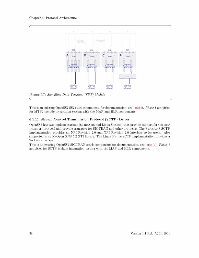
Figure 6.7: Signalling Data Terminal (SDT) Module This is an existing OpenSS7 SS7 stack component; for documentation, see: sdt(4). Phase 1 activitiesfor MTP2 include integration testing with the MAP and HLR components.
6.1.11 Stream Control Transmission Protocol (SCTP) Driver
OpenSS7 has two implementations (STREAMS and Linux Sockets) that provide support for this newtransport protocol and provide transport for SIGTRAN and other protocols. The STREAMS SCTPimplementation provides an NPI Revision 2.0 and TPI Revision 2.0 interface to its users. Alsosupported is an X/Open XNS 5.2 XTI library. The Linux Native SCTP implementation provides aSockets interface.
This is an existing OpenSS7 SIGTRAN stack component; for documentation, see: sctp(4). Phase 1activities for SCTP include integration testing with the MAP and HLR components.
38 Version 1.1 Rel. 7.20141001
High Performance HLR Software Architecture
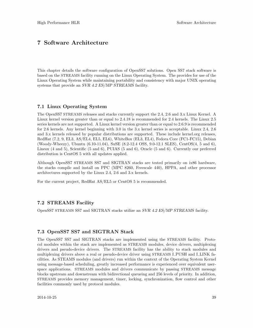
7 Software Architecture
This chapter details the software configuration of OpenSS7 solutions. Open SS7 stack software isbased on the STREAMS facility running on the Linux Operating System. The provides for use of theLinux Operating System while maintaining portability and consistency with major UNIX operatingsystems that provide an SVR 4.2 ES/MP STREAMS facility.
7.1 Linux Operating System
The OpenSS7 STREAMS releases and stacks currently support the 2.4, 2.6 and 3.x Linux Kernel. ALinux kernel version greater than or equal to 2.4.18 is recommended for 2.4 kernels. The Linux 2.5series kernels are not supported. A Linux kernel version greater than or equal to 2.6.9 is recommendedfor 2.6 kernels. Any kernel beginning with 3.0 in the 3.x kernel series is acceptable. Linux 2.4, 2.6and 3.x kernels released by popular distributions are supported. These include kernel.org releases,RedHat (7.2, 9, EL3, AS/EL4, EL5, EL6), WhiteBox (EL3, EL4), Fedora Core (FC1-FC15), Debian(Woody-Wheezy), Ubuntu (6.10-11.04), SuSE (8.2-12.4 OSS, 9.0-12.1 SLES), CentOS(4, 5 and 6),Lineox (4 and 5), Scientific (5 and 6), PUIAS (5 and 6), Oracle (5 and 6). Currently our preferreddistribution is CentOS 5 with all updates applied.
Although OpenSS7 STREAMS SS7 and SIGTRAN stacks are tested primarily on ix86 hardware,the stacks compile and install on PPC (MPC 8260, Freescale 440), HPPA, and other processorarchitectures supported by the Linux 2.4, 2.6 and 3.x kernels.
For the current project, RedHat AS/EL5 or CentOS 5 is recommended.
7.2 STREAMS Facility
OpenSS7 STREAMS SS7 and SIGTRAN stacks utilize an SVR 4.2 ES/MP STREAMS facility.
7.3 OpenSS7 SS7 and SIGTRAN Stack
The OpenSS7 SS7 and SIGTRAN stacks are implemented using the STREAMS facility. Proto-col modules within the stack are implemented as STREAMS modules, device drivers, multiplexingdrivers and pseudo-device drivers. The STREAMS facility has the ability to stack modules andmultiplexing drivers above a real or pseudo-device driver using STREAMS I PUSH and I LINK fa-cilities. As STEAMS modules (and drivers) run within the context of the Operating System Kernelusing message-based scheduling, greatly increased performance is experienced over equivalent user-space applications. STREAMS modules and drivers communicate by passing STREAMS messageblocks upstream and downstream with bidirectional queueing and 256 levels of priority. In addition,STREAMS provides memory management, timer, locking, synchronization, flow control and otherfacilities commonly used by protocol modules.
2014-10-25 39
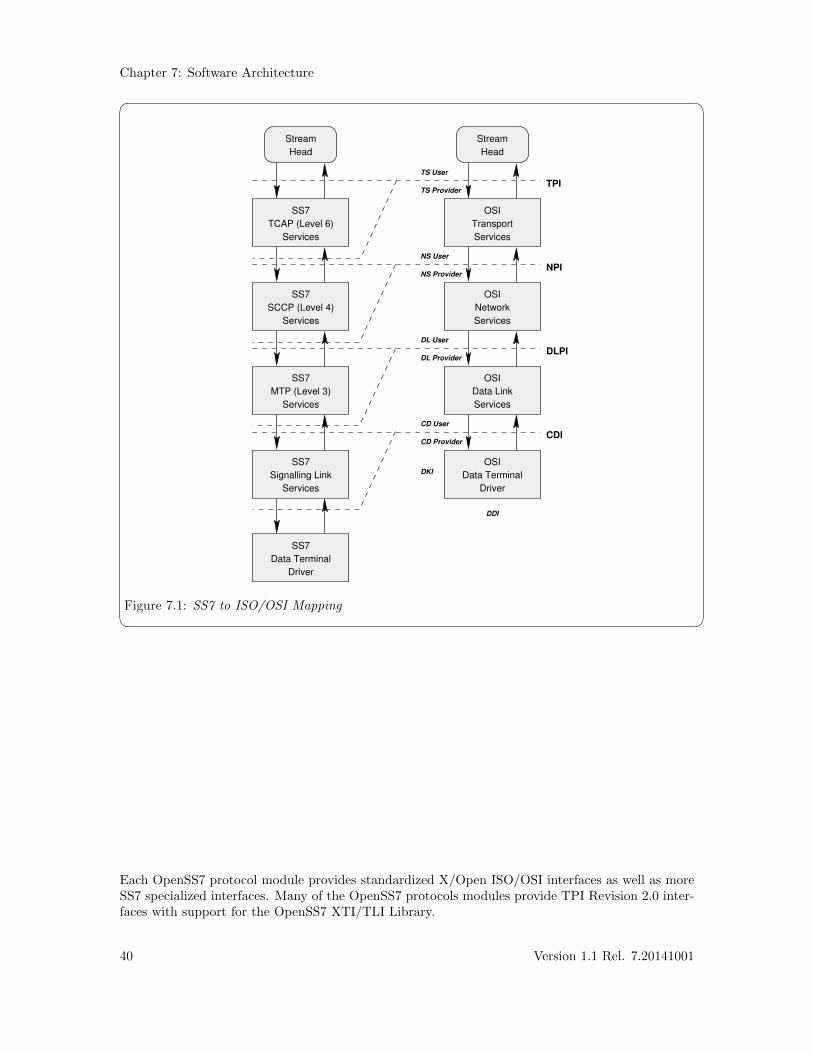
Chapter 7: Software Architecture
� �
SS7
TCAP (Level 6)
Services
SS7
SCCP (Level 4)
Services
SS7
MTP (Level 3)
Services
SS7
Signalling Link
Services
SS7
Data Terminal
Driver
OSI
Data Terminal
Driver
OSI
Data Link
Services
OSI
Network
Services
OSI
Transport
Services
Stream
Head
Stream
Head
TS User
TS Provider
NS User
NS Provider
DL User
DL Provider
CD User
CD Provider
DKI
DDI
TPI
NPI
DLPI
CDI
Figure 7.1: SS7 to ISO/OSI Mapping
Each OpenSS7 protocol module provides standardized X/Open ISO/OSI interfaces as well as moreSS7 specialized interfaces. Many of the OpenSS7 protocols modules provide TPI Revision 2.0 inter-faces with support for the OpenSS7 XTI/TLI Library.
40 Version 1.1 Rel. 7.20141001
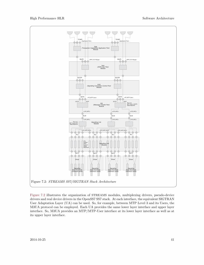
High Performance HLR Software Architecture
� �
tcap(Transaction Capabilities Application Part)
Module
<Application-Part> <Application Part>
mtp(Message Transfer Part)
Module
<LPC,APC> <LPC,APC> <LPC,APC>
Per-muxSS7 Leve 3 (MTP)State Machine
SLSI SLSI SLSI
SignallingData Terminals(Interface cards)
SignallingData Terminals(Interface cards)
SignallingData Terminals(Interface cards)
SignallingData Terminals(Interface cards)
Driver Driver Driver Driver
SDTI SDTI SDTI SDTI
PerstreamSS7Level 2StateMachine
SLI SLI SLI SLI
Signalling LinkModule
Per-muxSS7 Level LinkState Machine
Signalling LinkModule
sccp(Signalling Connection Control Part)
Module
SCCP SCCP
isup(ISDN User Part)
Module
<RPC,CIC-Range> <RPC,CIC-Range>
<PC,MTP-User> <PC,MTP-User>MTPI MTPI
SCCPI SCCPI
ISUPI ISUPI
TCAPI TCAPI
ISUP ISUP
<LPC,APC> <LPC,APC> <LPC,APC>
<LPC,APC,SLS> <LPC,APC,SLS> <LPC,APC,SLS>
Figure 7.2: STREAMS SS7/SIGTRAN Stack Architecture Figure 7.2 illustrates the organization of STREAMS modules, multiplexing drivers, pseudo-devicedrivers and real device drivers in the OpenSS7 SS7 stack. At each interface, the equivalent SIGTRANUser Adaptation Layer (UA) can be used. So, for example, between MTP Level 3 and its Users, theM3UA protocol can be employed. Each UA provides the same lower layer interface and upper layerinterface. So, M3UA provides an MTP/MTP-User interface at its lower layer interface as well as atits upper layer interface.
2014-10-25 41

High Performance HLR Hardware Architecture
8 Hardware Architecture
Figure 8.1 illustrates the hardware configuration for the High Performance GSM/UMTS GPRS HLRevaluation platform.� �
4 x 10/100 baseTNIC
AdministrativeWorkstation
1 x 10/100 baseTNIC
ix86Uni Processor
In-Memory HLREvaluationPlatform
SS7Signalling
Network
M3UAM3UA
SignallingGateway
Appache1.3.22
Perl5.6.1
LiS STREAMS2.16.18
Linux Kernel2.4.21
LinuxDistributionWhiteBox
EL3
4 x E1 SS7
E400P-SS7
4 x E1 SS7
E400P-SS7
8 E1 spans. Spans can be run fully channelized with 31 64kbps Q.703 signalling links or 1 2.048Mbps Q.703 Annex B high-speed signalling links. Each T1 span can be configured fully channelized or unchannelized.
4 10/100 baseT NICs. Each NIC can be multihomed on a different Ethernet segment and IP subnetwork for redundancy. These NICs are not required until M3UA is to be deployed in the test environment.
Figure 8.1: Platform Architecture The High Performance GSM/UMTS GPRS HLR prototype platform consists of a medium end ix86single processor PC in a hardened 19" rack mount chassis, loaded with WBEL3 Linux runninga 2.4.21 kernel, openss7-1.1.7.20141001, the OpenSS7 stack (strss7-0.9.2-1) software and the HighPerformance GSM/UMTS GPRS HLR application.
SS7 or SIGTRAN signalling links are terminated either on E400P-SS7 cards (or other OpenSS7compatible E1 cards) directly attached to the test platform, or via Signalling Gateway devicesback-hauling M2UA, M3UA or SUA to the test platform over an internal LAN connection.
OAM&P of the prototype platform is performed over an internal LAN connection.
Hardware requirements are as follows:
• 1 x medium end (2.0 GHz) single processor, 19" rack mount, hardened chassis PC, 110 VACcommercial power.
• 2 x E400-SS7 Cards (or equivalent).
• 4 x 100baseT Ethernet NICs (3com 905B or equivalent).
For a redundant configuration (two hosts serving the same gateway), twice the hardware is required.
2014-10-25 43
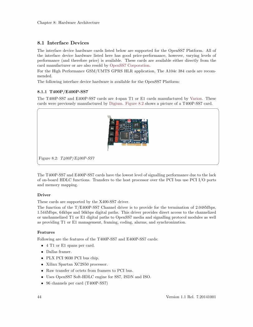
Chapter 8: Hardware Architecture
8.1 Interface Devices
The interface device hardware cards listed below are supported for the OpenSS7 Platform. All ofthe interface device hardware listed here has good price-performance, however, varying levels ofperformance (and therefore price) is available. These cards are available either directly from thecard manufacturer or are also resold by OpenSS7 Corporation.
For the High Performance GSM/UMTS GPRS HLR application, The A104c 384 cards are recom-mended.
The following interface device hardware is available for the OpenSS7 Platform:
8.1.1 T400P/E400P-SS7
The T400P-SS7 and E400P-SS7 cards are 4-span T1 or E1 cards manufactured by Varion. Thesecards were previously manufactured by Digium. Figure 8.2 shows a picture of a T400P-SS7 card.� �
Figure 8.2: T400P/E400P-SS7 The T400P-SS7 and E400P-SS7 cards have the lowest level of signalling performance due to the lackof on-board HDLC functions. Transfers to the host processor over the PCI bus use PCI I/O portsand memory mapping.
Driver
These cards are supported by the X400-SS7 driver.
The function of the T/E400P-SS7 Channel driver is to provide for the termination of 2.048Mbps,1.544Mbps, 64kbps and 56kbps digital paths. This driver provides direct access to the channelizedor unchannelized T1 or E1 digital paths to OpenSS7 media and signalling protocol modules as wellas providing T1 or E1 management, framing, coding, alarms, and synchronization.
Features
Following are the features of the T400P-SS7 and E400P-SS7 cards:
• 4 T1 or E1 spans per card.
• Dallas framer.
• PLX PCI 9030 PCI bus chip.
• Xilinx Spartan XC2S50 processor.
• Raw transfer of octets from framers to PCI bus.
• Uses OpenSS7 Soft-HDLC engine for SS7, ISDN and ISO.
• 96 channels per card (T400P-SS7)
44 Version 1.1 Rel. 7.20141001
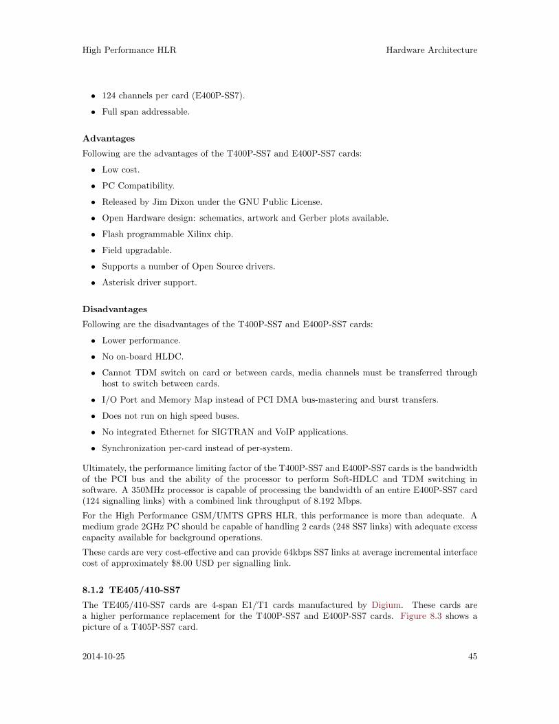
High Performance HLR Hardware Architecture
• 124 channels per card (E400P-SS7).
• Full span addressable.
Advantages
Following are the advantages of the T400P-SS7 and E400P-SS7 cards:
• Low cost.
• PC Compatibility.
• Released by Jim Dixon under the GNU Public License.
• Open Hardware design: schematics, artwork and Gerber plots available.
• Flash programmable Xilinx chip.
• Field upgradable.
• Supports a number of Open Source drivers.
• Asterisk driver support.
Disadvantages
Following are the disadvantages of the T400P-SS7 and E400P-SS7 cards:
• Lower performance.
• No on-board HLDC.
• Cannot TDM switch on card or between cards, media channels must be transferred throughhost to switch between cards.
• I/O Port and Memory Map instead of PCI DMA bus-mastering and burst transfers.
• Does not run on high speed buses.
• No integrated Ethernet for SIGTRAN and VoIP applications.
• Synchronization per-card instead of per-system.
Ultimately, the performance limiting factor of the T400P-SS7 and E400P-SS7 cards is the bandwidthof the PCI bus and the ability of the processor to perform Soft-HDLC and TDM switching insoftware. A 350MHz processor is capable of processing the bandwidth of an entire E400P-SS7 card(124 signalling links) with a combined link throughput of 8.192 Mbps.
For the High Performance GSM/UMTS GPRS HLR, this performance is more than adequate. Amedium grade 2GHz PC should be capable of handling 2 cards (248 SS7 links) with adequate excesscapacity available for background operations.
These cards are very cost-effective and can provide 64kbps SS7 links at average incremental interfacecost of approximately $8.00 USD per signalling link.
8.1.2 TE405/410-SS7
The TE405/410-SS7 cards are 4-span E1/T1 cards manufactured by Digium. These cards area higher performance replacement for the T400P-SS7 and E400P-SS7 cards. Figure 8.3 shows apicture of a T405P-SS7 card.
2014-10-25 45
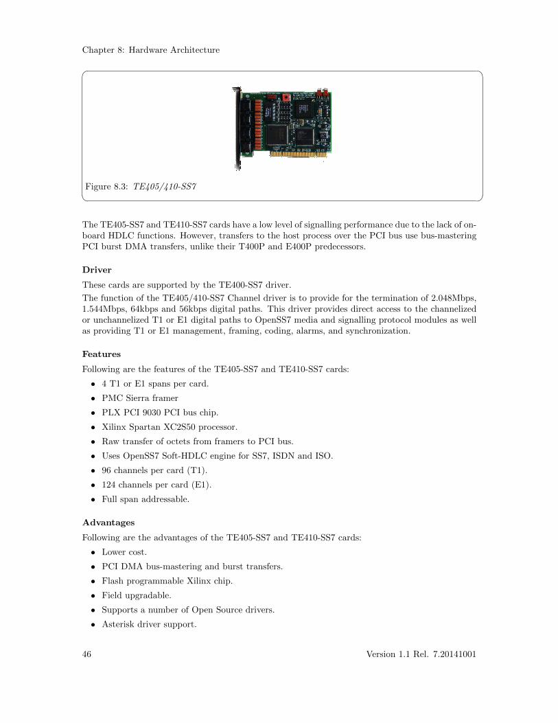
Chapter 8: Hardware Architecture
� �
Figure 8.3: TE405/410-SS7 The TE405-SS7 and TE410-SS7 cards have a low level of signalling performance due to the lack of on-board HDLC functions. However, transfers to the host process over the PCI bus use bus-masteringPCI burst DMA transfers, unlike their T400P and E400P predecessors.
Driver
These cards are supported by the TE400-SS7 driver.
The function of the TE405/410-SS7 Channel driver is to provide for the termination of 2.048Mbps,1.544Mbps, 64kbps and 56kbps digital paths. This driver provides direct access to the channelizedor unchannelized T1 or E1 digital paths to OpenSS7 media and signalling protocol modules as wellas providing T1 or E1 management, framing, coding, alarms, and synchronization.
Features
Following are the features of the TE405-SS7 and TE410-SS7 cards:
• 4 T1 or E1 spans per card.
• PMC Sierra framer
• PLX PCI 9030 PCI bus chip.
• Xilinx Spartan XC2S50 processor.
• Raw transfer of octets from framers to PCI bus.
• Uses OpenSS7 Soft-HDLC engine for SS7, ISDN and ISO.
• 96 channels per card (T1).
• 124 channels per card (E1).
• Full span addressable.
Advantages
Following are the advantages of the TE405-SS7 and TE410-SS7 cards:
• Lower cost.
• PCI DMA bus-mastering and burst transfers.
• Flash programmable Xilinx chip.
• Field upgradable.
• Supports a number of Open Source drivers.
• Asterisk driver support.
46 Version 1.1 Rel. 7.20141001
High Performance HLR Hardware Architecture
Disadvantages
Following are the disadvantages of the TE405-SS7 and TE410-SS7 cards:
• Lower performance, although better than predecessor.
• No on-board HLDC.
• Cannot TDM switch on card or between cards, media channels must be transferred throughhost to switch between cards.
• No integrated Ethernet for SIGTRAN and VoIP applications.
• Synchronization per-card instead of per-system.
As with their predecessors, the performance limiting factor of the TE405-SS7 and TE410-SS7 cardsis the bandwidth of the PCI bus and the ability of the processor to perform Soft-HDLC and TDMswitching in software. A 350MHz processor is capable of processing the bandwidth of an entireTE405-SS7 card (124 signalling link) with a combined linke throughput of 8.192 Mbps.
For the High Performance GSM/UMTS HLR, this performance is more than adequate. A mediumgrade 2GHz PC should be capable of handling 2 cards (248 SS7 links) with adequate excess capacityavailable for background operations.
These cards are cost-effective and can provide 64kbps SS7 links at average incremental interface costof approximately $12.00 USD per signalling link.
8.1.3 A101/102/104c
The A101/102/104c cards are 1-, 2- and 4-span E1, T1 or J1 cards manufactured by Sangoma.Figure 8.4 shows a picture of an A101c card.� �
Figure 8.4: A101/102/104c The A10Xc cards have an increased level of signalling performance due to availability of on-boardHDLC processing. Transfers to the host are performed using bus-mastering PCI DMA burst transfersfor lower host processor overhead. These cards do not support direct on-board TDM switching;neither do they have integrated Ethernet.
Driver
These cards are supported by the A100-SS7 driver.
The function of the A100-SS7 Channel driver is to provide for the termination of 2.048Mbps,1.544Mbps, 64kbps and 56kbps digital paths. This driver provides direct access to the channel-ized or unchannelized T1 or E1 digital paths to OpenSS7 media and signalling protocol modules aswell as providing T1 or E1 management, framing, coding, alarms, and synchronization.
2014-10-25 47
Chapter 8: Hardware Architecture
Features
Following are the features of the A101c, A102c and A104c cards:
• 1, 2 or 4 E1 spans per card.
• PMC Comet framer.
• Xilinx Spartan XC2S50 processor.
• Raw transfer of octets from framers to PCI bus.
• Can use OpenSS7 Soft-HDLC engines for SS7, ISDN and ISO.
• Also provides for onboard HLDC (SS7 DAEDR/DAEDT AERM/SUERM).
• 24, 48 and 96 channels per card (T1 A101, A102 and A104).
• 31, 62 and 124 channels per card (E1 A101, A102 and A104).
• Full span addressable.
Advantages
Following are the advantages of the A101, A102 and A104 cards:
• Low cost.
• PC Comaptibility.
• Homolgomation and world-wide support.
• Flash programmable Xilinx chip.
• Field upgradable.
• Supports a wide range of Open Source drivers.
• Linux kernel WAN support.
• Asterisk driver support.
Disadvantages
Following are the disadvantages of the A101, A102 and A104 cards:
• Cannot TDM switch on card or between cards, media channels must be transferred throughhost to switch between cards.
• No integrated Ethernet for SIGTRAN and VoIP applications.
• Synchronization per-card instead of per-system.
The performance limiting factor of the A101c, A102c and A104c cards is the bandwidth of the PCIbus and the ability of the processor to perform TDM switching is software.
For the High Performance GMS/UMTS GPRS HLR, this performance is more than adequate, par-ticularly as TDM switching is not a requirement for this pure signalling application. Althoughthese cards lack integrated Ethernet support, for the non-redundant HLR application, and whereinterworking between SIGTRAN and SS7 is not required, this is not a limitation.
These cards have excellent price-performance and can provide 64kbps SS7 links at average incre-mental interface cost of approximately $12.00 USD per signalling link.
8.1.4 Other Interface Cards
Additional interface cards could be implemented in other phases of the project. For additionalinformation, see Appendix E [Optional Hardware Support], page 69.
48 Version 1.1 Rel. 7.20141001
High Performance HLR Logistics
9 Logistics
Following are estimates of hardware, software, consulting, schedule and costs:
9.1 Hardware
Prototype hardware sufficient for trial of all projects consists of the following:
• 2 x high-end (2.0 GHz) PCs
• 6 x NICs (3 for each PC)
• 4 x A104 Cards (2 for each PC)
9.1.1 Sizing Considerations
Sizing provided here is adequate to meet the scale requirements under Chapter 4 [System Architec-ture], page 25. For detail on sizing, see Appendix G [Platform Sizing], page 77.
9.2 Software
Prototype software sufficient for trial of all projects consists of the following:
• WhiteBox EL3 Linux distribution (or equivalent)
• Linux 2.4.21 kernel (GPL, download)
• Linux Fast-STREAMS (openss7-1.1.7.20141001 or equivalent, GPL download)
• OpenSS7 CVS access
• OpenSS7 components listed under project
9.3 Consulting
Consulting consists of the following:
• Completion of OpenSS7 components marked as "incomplete" under project description suitablefor use for prototype.
• Development and documentation of "application" components under project descriptions.
• Loading and configuring software for evaluation platforms.
• Participating in evaluation testing.
• Answering questions and providing guidance to client staff on the use and testing of the evalu-ation platform.
9.4 Schedule
Below is an estimated schedule. The estimate considers that OpenSS7 staff would be performingall development work and that Gamma client or Sponsor would participate in external gate reviewsand acceptance testing in a timely manner.
Table 9.1 lists the initial (Gate 0) schedule estimates.
2014-10-25 49
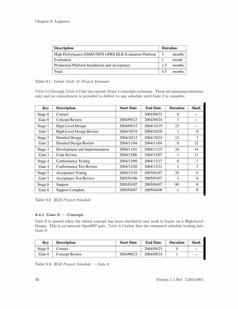
Chapter 9: Logistics
Description Duration
High Performance GSM/UMTS GPRS HLR Evaluation Platform 2 months
Evaluation 1 month
Production Platform Installation and Acceptance 1.5 months
Total 4.5 months
Table 9.1: Initial (Gate 0) Project Estimate
Table 9.2 through Table 9.9 list the current (Gate 1) schedule estimates. These are planning estimatesonly and no commitment is provided to deliver to any schedule until Gate 2 is complete.
Key Description Start Date End Date Duration Slack
Stage 0 Contact 2004/09/23 0 −
Gate 0 Concept Review 2004/09/23 2004/09/24 1 −
Stage 1 High-Level Design 2004/09/23 2004/10/19 23 −
Gate 1 High-Level Design Review 2004/10/19 2004/10/20 1 -4
Stage 2 Detailed Design 2004/10/12 2004/10/24 12 7
Gate 2 Detailed Design Review 2004/11/04 2004/11/04 0 12
Stage 3 Development and Implementation 2004/11/01 2004/11/25 24 14
Gate 3 Code Review 2004/12/06 2004/12/07 1 11
Stage 4 Conformance Testing 2004/12/09 2004/12/17 6 -7
Gate 4 Conformance Test Review 2004/12/20 2004/12/21 1 3
Stage 5 Acceptance Testing 2004/12/10 2005/01/07 28 0
Gate 5 Acceptance Test Review 2005/01/06 2005/01/07 1 0
Stage 6 Support 2005/01/07 2005/04/07 90 0
Gate 6 Support Complete 2005/04/07 2005/04/08 1 0
Table 9.2: HLR Project Schedule
9.4.1 Gate 0 — Concept
Gate 0 is passed when the initial concept has been elucidated and work is begun on a High-LevelDesign. This is an internal OpenSS7 gate. Table 9.3 below lists the estimated schedule leading intoGate 0.
Key Description Start Date End Date Duration Slack
Stage 0 Contact 2004/09/23 0 −
Gate 0 Concept Review 2004/09/23 2004/09/24 1 −
Table 9.3: HLR Project Schedule — Gate 0
50 Version 1.1 Rel. 7.20141001
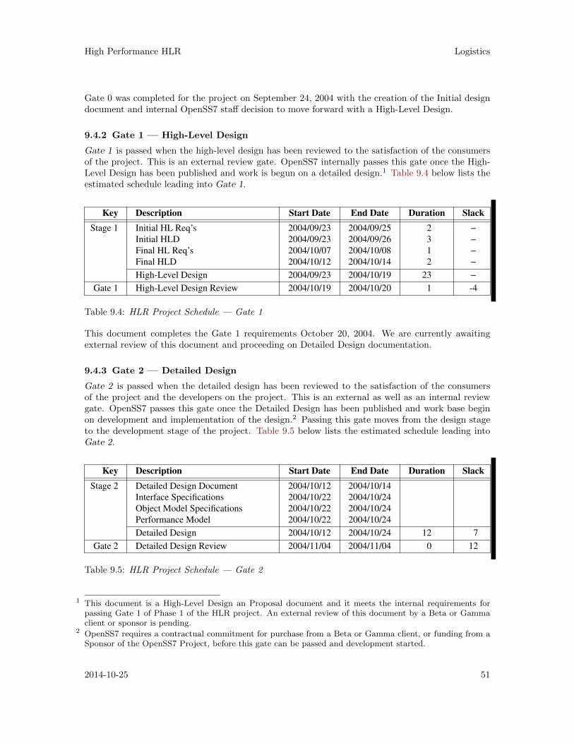
High Performance HLR Logistics
Gate 0 was completed for the project on September 24, 2004 with the creation of the Initial designdocument and internal OpenSS7 staff decision to move forward with a High-Level Design.
9.4.2 Gate 1 — High-Level Design
Gate 1 is passed when the high-level design has been reviewed to the satisfaction of the consumersof the project. This is an external review gate. OpenSS7 internally passes this gate once the High-Level Design has been published and work is begun on a detailed design.1 Table 9.4 below lists theestimated schedule leading into Gate 1.
Key Description Start Date End Date Duration Slack
Stage 1 Initial HL Req’s 2004/09/23 2004/09/25 2 −
Initial HLD 2004/09/23 2004/09/26 3 −
Final HL Req’s 2004/10/07 2004/10/08 1 −
Final HLD 2004/10/12 2004/10/14 2 −
High-Level Design 2004/09/23 2004/10/19 23 −
Gate 1 High-Level Design Review 2004/10/19 2004/10/20 1 -4
Table 9.4: HLR Project Schedule — Gate 1
This document completes the Gate 1 requirements October 20, 2004. We are currently awaitingexternal review of this document and proceeding on Detailed Design documentation.
9.4.3 Gate 2 — Detailed Design
Gate 2 is passed when the detailed design has been reviewed to the satisfaction of the consumersof the project and the developers on the project. This is an external as well as an internal reviewgate. OpenSS7 passes this gate once the Detailed Design has been published and work base beginon development and implementation of the design.2 Passing this gate moves from the design stageto the development stage of the project. Table 9.5 below lists the estimated schedule leading intoGate 2.
Key Description Start Date End Date Duration Slack
Stage 2 Detailed Design Document 2004/10/12 2004/10/14
Interface Specifications 2004/10/22 2004/10/24
Object Model Specifications 2004/10/22 2004/10/24
Performance Model 2004/10/22 2004/10/24
Detailed Design 2004/10/12 2004/10/24 12 7
Gate 2 Detailed Design Review 2004/11/04 2004/11/04 0 12
Table 9.5: HLR Project Schedule — Gate 2
1 This document is a High-Level Design an Proposal document and it meets the internal requirements forpassing Gate 1 of Phase 1 of the HLR project. An external review of this document by a Beta or Gammaclient or sponsor is pending.
2 OpenSS7 requires a contractual commitment for purchase from a Beta or Gamma client, or funding from aSponsor of the OpenSS7 Project, before this gate can be passed and development started.
2014-10-25 51
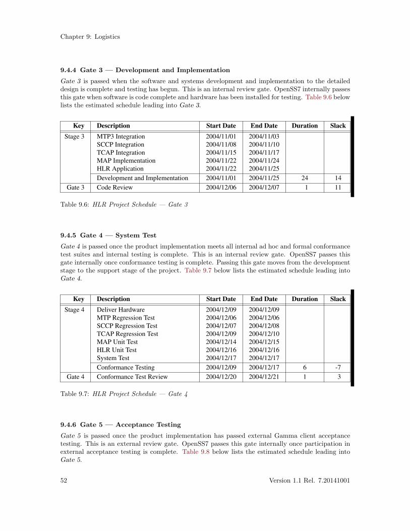
Chapter 9: Logistics
9.4.4 Gate 3 — Development and Implementation
Gate 3 is passed when the software and systems development and implementation to the detaileddesign is complete and testing has begun. This is an internal review gate. OpenSS7 internally passesthis gate when software is code complete and hardware has been installed for testing. Table 9.6 belowlists the estimated schedule leading into Gate 3.
Key Description Start Date End Date Duration Slack
Stage 3 MTP3 Integration 2004/11/01 2004/11/03
SCCP Integration 2004/11/08 2004/11/10
TCAP Integration 2004/11/15 2004/11/17
MAP Implementation 2004/11/22 2004/11/24
HLR Application 2004/11/22 2004/11/25
Development and Implementation 2004/11/01 2004/11/25 24 14
Gate 3 Code Review 2004/12/06 2004/12/07 1 11
Table 9.6: HLR Project Schedule — Gate 3
9.4.5 Gate 4 — System Test
Gate 4 is passed once the product implementation meets all internal ad hoc and formal conformancetest suites and internal testing is complete. This is an internal review gate. OpenSS7 passes thisgate internally once conformance testing is complete. Passing this gate moves from the developmentstage to the support stage of the project. Table 9.7 below lists the estimated schedule leading intoGate 4.
Key Description Start Date End Date Duration Slack
Stage 4 Deliver Hardware 2004/12/09 2004/12/09
MTP Regression Test 2004/12/06 2004/12/06
SCCP Regression Test 2004/12/07 2004/12/08
TCAP Regression Test 2004/12/09 2004/12/10
MAP Unit Test 2004/12/14 2004/12/15
HLR Unit Test 2004/12/16 2004/12/16
System Test 2004/12/17 2004/12/17
Conformance Testing 2004/12/09 2004/12/17 6 -7
Gate 4 Conformance Test Review 2004/12/20 2004/12/21 1 3
Table 9.7: HLR Project Schedule — Gate 4
9.4.6 Gate 5 — Acceptance Testing
Gate 5 is passed once the product implementation has passed external Gamma client acceptancetesting. This is an external review gate. OpenSS7 passes this gate internally once participation inexternal acceptance testing is complete. Table 9.8 below lists the estimated schedule leading intoGate 5.
52 Version 1.1 Rel. 7.20141001
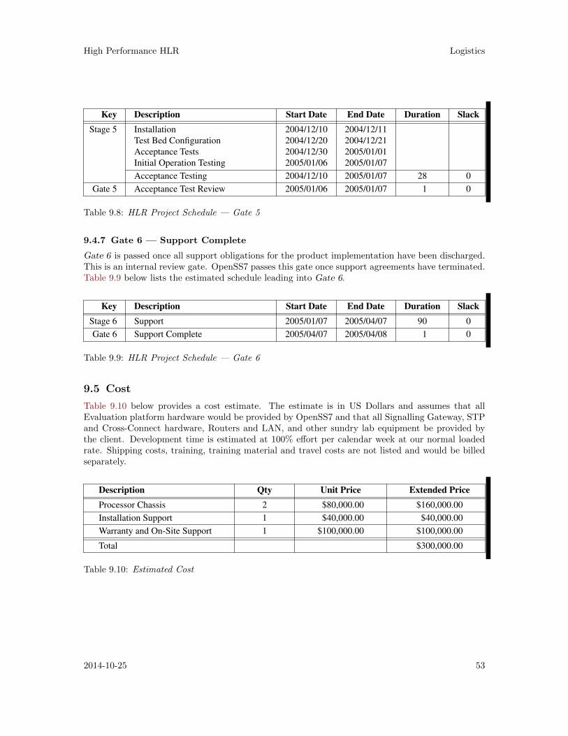
High Performance HLR Logistics
Key Description Start Date End Date Duration Slack
Stage 5 Installation 2004/12/10 2004/12/11
Test Bed Configuration 2004/12/20 2004/12/21
Acceptance Tests 2004/12/30 2005/01/01
Initial Operation Testing 2005/01/06 2005/01/07
Acceptance Testing 2004/12/10 2005/01/07 28 0
Gate 5 Acceptance Test Review 2005/01/06 2005/01/07 1 0
Table 9.8: HLR Project Schedule — Gate 5
9.4.7 Gate 6 — Support Complete
Gate 6 is passed once all support obligations for the product implementation have been discharged.This is an internal review gate. OpenSS7 passes this gate once support agreements have terminated.Table 9.9 below lists the estimated schedule leading into Gate 6.
Key Description Start Date End Date Duration Slack
Stage 6 Support 2005/01/07 2005/04/07 90 0
Gate 6 Support Complete 2005/04/07 2005/04/08 1 0
Table 9.9: HLR Project Schedule — Gate 6
9.5 Cost
Table 9.10 below provides a cost estimate. The estimate is in US Dollars and assumes that allEvaluation platform hardware would be provided by OpenSS7 and that all Signalling Gateway, STPand Cross-Connect hardware, Routers and LAN, and other sundry lab equipment be provided bythe client. Development time is estimated at 100% effort per calendar week at our normal loadedrate. Shipping costs, training, training material and travel costs are not listed and would be billedseparately.
Description Qty Unit Price Extended Price
Processor Chassis 2 $80,000.00 $160,000.00
Installation Support 1 $40,000.00 $40,000.00
Warranty and On-Site Support 1 $100,000.00 $100,000.00
Total $300,000.00
Table 9.10: Estimated Cost
2014-10-25 53

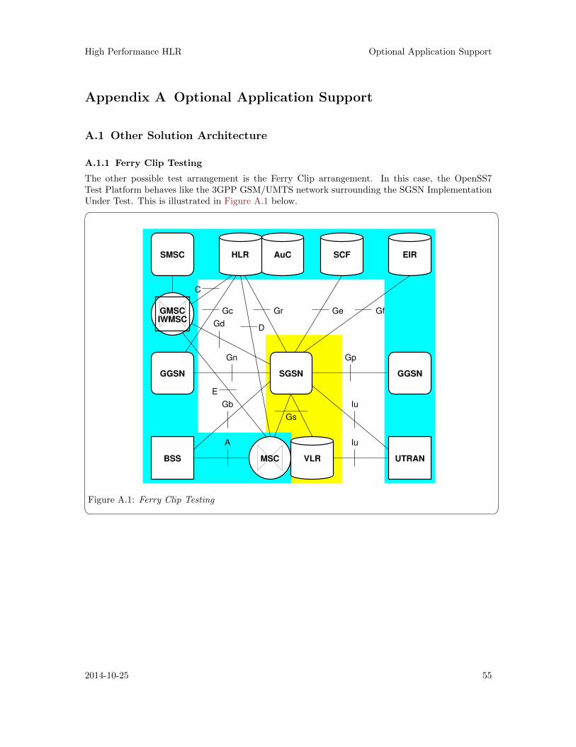
High Performance HLR Optional Application Support
Appendix A Optional Application Support
A.1 Other Solution Architecture
A.1.1 Ferry Clip Testing
The other possible test arrangement is the Ferry Clip arrangement. In this case, the OpenSS7Test Platform behaves like the 3GPP GSM/UMTS network surrounding the SGSN ImplementationUnder Test. This is illustrated in Figure A.1 below.� �
MSC UTRAN
GGSN
GMSC
IWMSC
SMSC
GGSN SGSN
BSS
Gs
GeGrGc
Gb
A
Iu
Iu
E
GpGn
GdD
C
Gf
EIRSCFAuCHLR
VLR
Figure A.1: Ferry Clip Testing
2014-10-25 55

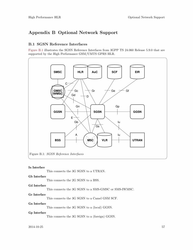
High Performance HLR Optional Network Support
Appendix B Optional Network Support
B.1 SGSN Reference Interfaces
Figure B.1 illustrates the SGSN Reference Interfaces from 3GPP TS 24.060 Release 5.9.0 that aresupported by the High Performance GSM/UMTS GPRS HLR.� �
MSC UTRAN
GGSN
GMSC
IWMSC
SMSC
GGSN SGSN
BSS
Gs
GeGrGc
Gb
A
Iu
Iu
E
GpGn
GdD
C
Gf
EIRSCFAuCHLR
VLR
Figure B.1: SGSN Reference Interfaces Iu Interface
This connects the 3G SGSN to a UTRAN.
Gb InterfaceThis connects the 2G SGSN to a BSS.
Gd InterfaceThis connects the 3G SGSN to a SMS-GMSC or SMS-IWMSC.
Ge InterfaceThis connects the 3G SGSN to a Camel GSM SCF.
Gn InterfaceThis connects the 3G SGSN to a (local) GGSN.
Gp InterfaceThis connects the 3G SGSN to a (foreign) GGSN.
2014-10-25 57
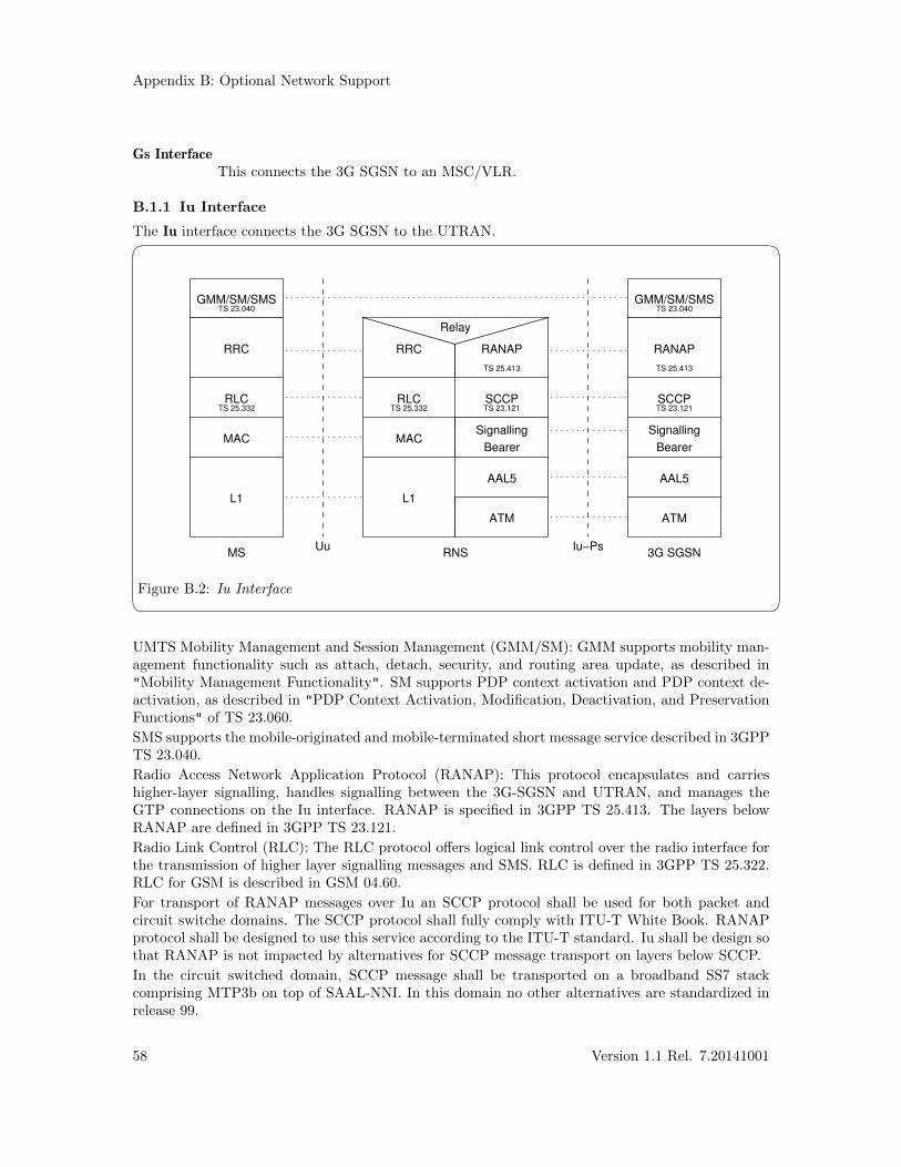
Appendix B: Optional Network Support
Gs InterfaceThis connects the 3G SGSN to an MSC/VLR.
B.1.1 Iu Interface
The Iu interface connects the 3G SGSN to the UTRAN.� �
AAL5AAL5
L1 L1
MS
SCCP
MAC
RLC
RRC
MAC
RLC
Relay
RRC RANAP
Signalling
Bearer
Signalling
Bearer
SCCP
RANAP
RNSUu Iu−Ps
ATM ATM
3G SGSN
GMM/SM/SMSGMM/SM/SMS
TS 25.413
TS 25.332 TS 23.121
TS 23.040
TS 25.332
TS 25.413
TS 23.121
TS 23.040
Figure B.2: Iu Interface UMTS Mobility Management and Session Management (GMM/SM): GMM supports mobility man-agement functionality such as attach, detach, security, and routing area update, as described in"Mobility Management Functionality". SM supports PDP context activation and PDP context de-activation, as described in "PDP Context Activation, Modification, Deactivation, and PreservationFunctions" of TS 23.060.
SMS supports the mobile-originated and mobile-terminated short message service described in 3GPPTS 23.040.
Radio Access Network Application Protocol (RANAP): This protocol encapsulates and carrieshigher-layer signalling, handles signalling between the 3G-SGSN and UTRAN, and manages theGTP connections on the Iu interface. RANAP is specified in 3GPP TS 25.413. The layers belowRANAP are defined in 3GPP TS 23.121.
Radio Link Control (RLC): The RLC protocol offers logical link control over the radio interface forthe transmission of higher layer signalling messages and SMS. RLC is defined in 3GPP TS 25.322.RLC for GSM is described in GSM 04.60.
For transport of RANAP messages over Iu an SCCP protocol shall be used for both packet andcircuit switche domains. The SCCP protocol shall fully comply with ITU-T White Book. RANAPprotocol shall be designed to use this service according to the ITU-T standard. Iu shall be design sothat RANAP is not impacted by alternatives for SCCP message transport on layers below SCCP.
In the circuit switched domain, SCCP message shall be transported on a broadband SS7 stackcomprising MTP3b on top of SAAL-NNI. In this domain no other alternatives are standardized inrelease 99.
58 Version 1.1 Rel. 7.20141001
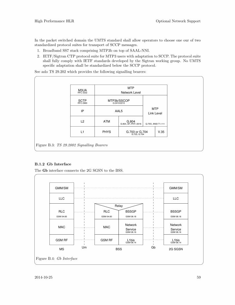
High Performance HLR Optional Network Support
In the packet switched domain the UMTS standard shall allow operators to choose one our of twostandardized protocol suites for transport of SCCP messages.
1. Broadband SS7 stack comprising MTP3b on top of SAAL-NNI.
2. IETF/Sigtran CTP protocol suite for MTP3 users with adaptation to SCCP. The protocol suiteshall fully comply with IETF standards developed by the Sigtran working group. No UMTSspecific adaptation shall be standardized below the SCCP protocol.
See aslo TS 29.202 which provides the following signalling bearers:� �
RFC 2960
RFC 3332
Q.2410/2210
Q.7XX, ANSI T1.111G.804, AF−PHY−0016
G.703, G.704
M3UA
SCTP
IP
L2
L1
MTP
Network Level
Link Level
MTP
V.35G.703 or G.704
G.804
AAL5
MTP3b/SSCOP
ATM
PHYS
Figure B.3: TS 29.2002 Signalling Bearers B.1.2 Gb Interface
The Gb interface connects the 2G SGSN to the BSS.� �
RLC
MAC
GSM RF
Network
Service
L1bis
BSSGP
MACNetwork
Service
GMM/SM
LLC LLC
GMM/SM
Gb2G SGSNBSS
UmMS
GSM RF
RLC
L1bis
BSSGP
Relay
GSM 08.18 GSM 08.18GSM 04.60GSM 04.60
GSM 08.16 GSM 08.16
GSM 08.14 GSM 08.14
Figure B.4: Gb Interface 2014-10-25 59
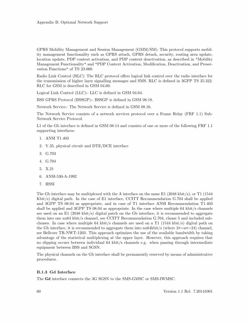
Appendix B: Optional Network Support
GPRS Mobility Management and Session Management (GMM/SM): This protocol supports mobil-ity management functionality such as GPRS attach, GPRS detach, security, routing area update,location update, PDP context activation, and PDP context deactivation, as described in "MobilityManagement Functionality" and "PDP Context Activation, Modification, Deactivation, and Preser-vation Functions" of TS 23.060.
Radio Link Control (RLC): The RLC protocol offers logical link control over the radio interface forthe transmission of higher layer signalling messages and SMS. RLC is defined in 3GPP TS 25.322.RLC for GSM is described in GSM 04.60.
Logical Link Control (LLC):- LLC is defined in GSM 04.64.
BSS GPRS Protocol (BSSGP):- BSSGP is defined in GSM 08.18.
Network Service:- The Network Service is defined in GSM 08.16.
The Network Service consists of a network services protocol over a Frame Relay (FRF 1.1) Sub-Network Service Protocol.
L1 of the Gb interface is defined in GSM 08.14 and consists of one or more of the following FRF 1.1supporting interfaces:
1. ANSI T1.403
2. V.35, physical circuit and DTE/DCE interface
3. G.703
4. G.704
5. X.21
6. ANSI-530-A-1992
7. HSSI
The Gb interface may be multiplexed with the A interface on the same E1 (2048 kbit/s), or T1 (1544Kbit/s) digital path. In the case of E1 interface, CCITT Recommendation G.704 shall be appliedand 3GPP TS 08.04 as appropriate, and in case of T1 interface ANSI Recommendation T1.403shall be applied and 3GPP TS 08.04 as appropriate. In the case where multiple 64 kbit/s channelsare used on an E1 (2048 kbit/s) digital patch on the Gb interface, it is recommended to aggregatethem into one nx64 kbit/s channel, see CCITT Recommendation G.704, clause 5 and included sub-clauses. In case where multiple 64 kbit/s channels are used on a T1 (1544 kbit/s) digital path onthe Gb interface, it is recommended to aggregate them into nx64kbit/s (where 2<=n<=24) channel,see Bellcore TR-NWT-1203. This approach optimizes the use of the available bandwidth by takingadvantage of the statistical multiplexing at the upper layer. However, this approach requires thatno slipping occurs between individual 64 kbit/s channels e.g. when passing through intermediateequipment between BSS and SGSN.
The physical channels on the Gb interface shall be permanently reserved by means of administrativeprocedures.
B.1.3 Gd Interface
The Gd interface connects the 3G SGSN to the SMS-GMSC or SMS-IWMSC.
60 Version 1.1 Rel. 7.20141001
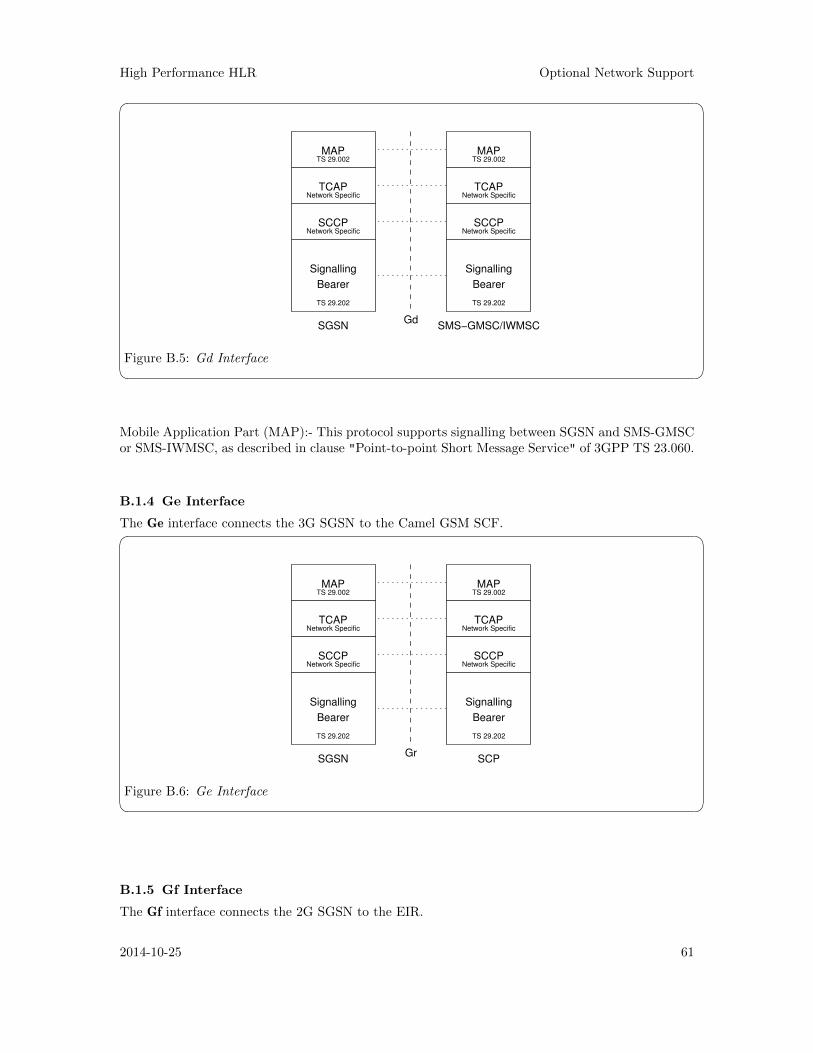
High Performance HLR Optional Network Support
� �MAP
TCAP
SCCP
Signalling
Bearer
MAP
TCAP
SCCP
Signalling
Bearer
SMS−GMSC/IWMSCSGSNGd
TS 29.002
TS 29.202
TS 29.002
TS 29.202
Network Specific Network Specific
Network SpecificNetwork Specific
Figure B.5: Gd Interface Mobile Application Part (MAP):- This protocol supports signalling between SGSN and SMS-GMSCor SMS-IWMSC, as described in clause "Point-to-point Short Message Service" of 3GPP TS 23.060.
B.1.4 Ge Interface
The Ge interface connects the 3G SGSN to the Camel GSM SCF.� �MAP
TCAP
SCCP
Signalling
Bearer
MAP
TCAP
SCCP
Signalling
Bearer
SCPSGSNGr
TS 29.002
TS 29.202 TS 29.202
TS 29.002
Network Specific Network Specific
Network SpecificNetwork Specific
Figure B.6: Ge Interface
B.1.5 Gf Interface
The Gf interface connects the 2G SGSN to the EIR.
2014-10-25 61
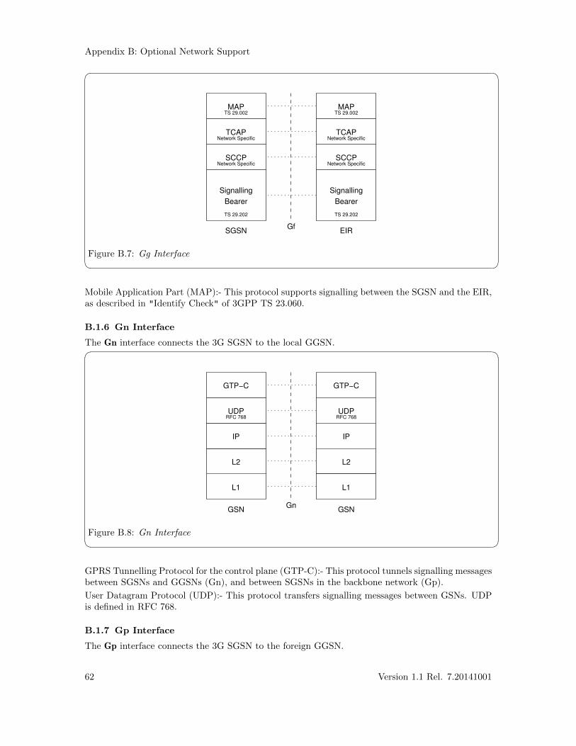
Appendix B: Optional Network Support
� �MAP
TCAP
SCCP
Signalling
Bearer
MAP
TCAP
SCCP
Signalling
Bearer
GfEIRSGSN
TS 29.002
TS 29.202 TS 29.202
TS 29.002
Network Specific Network Specific
Network SpecificNetwork Specific
Figure B.7: Gg Interface Mobile Application Part (MAP):- This protocol supports signalling between the SGSN and the EIR,as described in "Identify Check" of 3GPP TS 23.060.
B.1.6 Gn Interface
The Gn interface connects the 3G SGSN to the local GGSN.� �GTP−C
UDP UDP
IP IP
L2 L2
L1 L1
GSNGSNGn
GTP−C
RFC 768 RFC 768
Figure B.8: Gn Interface GPRS Tunnelling Protocol for the control plane (GTP-C):- This protocol tunnels signalling messagesbetween SGSNs and GGSNs (Gn), and between SGSNs in the backbone network (Gp).
User Datagram Protocol (UDP):- This protocol transfers signalling messages between GSNs. UDPis defined in RFC 768.
B.1.7 Gp Interface
The Gp interface connects the 3G SGSN to the foreign GGSN.
62 Version 1.1 Rel. 7.20141001
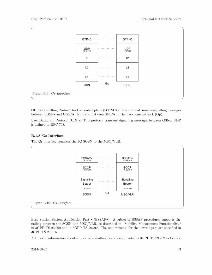
High Performance HLR Optional Network Support
� �GTP−C
UDP UDP
IP IP
L2 L2
L1 L1
GSNGSNGp
GTP−C
RFC 768 RFC 768
Figure B.9: Gp Interface GPRS Tunnelling Protocol for the control plane (GTP-C):- This protocol tunnels signalling messagesbetween SGSNs and GGSNs (Gn), and between SGSNs in the backbone network (Gp).
User Datagram Protocol (UDP):- This protocol transfers signalling messages between GSNs. UDPis defined in RFC 768.
B.1.8 Gs Interface
The Gs interface connects the 3G SGSN to the MSC/VLR.� �BSSAP+
SCCP
Signalling
Bearer
BSSAP+
SCCP
Signalling
Bearer
SGSN MSC/VLRGs
TS 29.016
TS 29.018
TS 29.202
TS 29.018
TS 29.016
TS 29.202
Figure B.10: Gs Interface Base Station System Application Part + (BSSAP+):- A subset of BSSAP procedures supports sig-nalling between the SGSN and MSC/VLR, as described in "Mobility Management Functionality"in 3GPP TS 23.060 and in 3GPP TS 29.018. The requirements for the lower layers are specified in3GPP TS 29.016.
Additional information about supported signalling bearers is provided in 3GPP TS 29.202 as follows:
2014-10-25 63
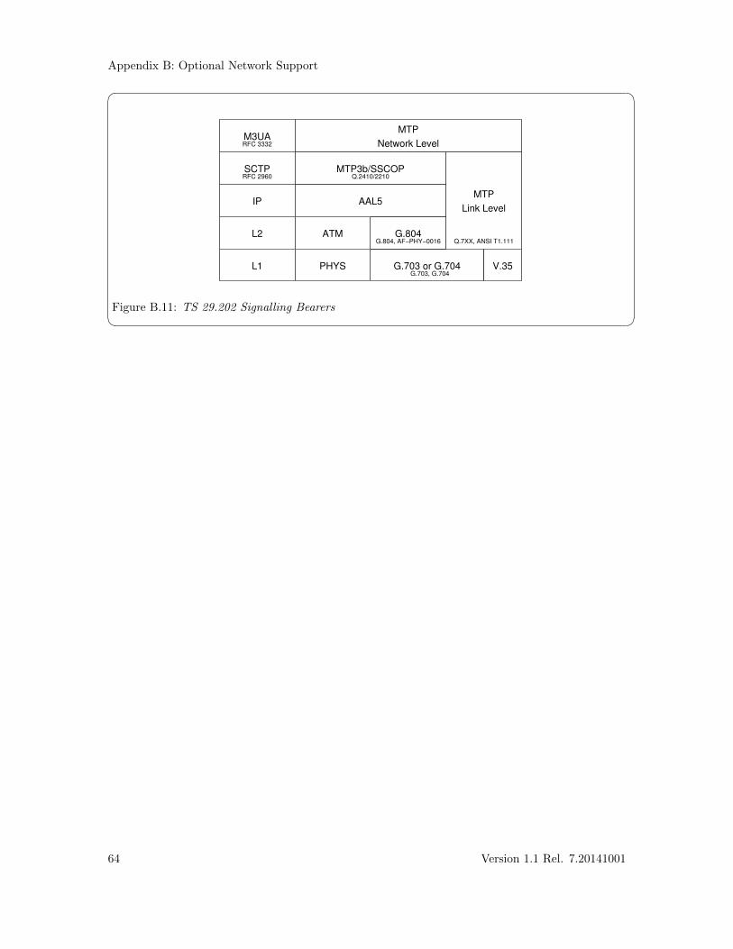
Appendix B: Optional Network Support
� �
RFC 2960
RFC 3332
Q.2410/2210
Q.7XX, ANSI T1.111G.804, AF−PHY−0016
G.703, G.704
M3UA
SCTP
IP
L2
L1
MTP
Network Level
Link Level
MTP
V.35G.703 or G.704
G.804
AAL5
MTP3b/SSCOP
ATM
PHYS
Figure B.11: TS 29.202 Signalling Bearers
64 Version 1.1 Rel. 7.20141001
High Performance HLR Optional Protocol Support
Appendix C Optional Protocol Support
C.1 Other Protocol Components
C.1.1 SCCP User Adaptation Layer (SUA) Driver
The SUA driver provides the HLR with the ability to act as an SUA AS (Application Server) inconjunction with an SUA SG (Signalling Gateway). In this project, the SG function is performed byexisting lab equipment. The SUA driver accepts the transport of the SCCP to SCCP-User interfacefrom the SG to the HLR. The SUA driver links SCTP driver streams underneath it to providethe transport services for exporting the SCCP-User interface. The SUA driver provides the sameinterfaces to its users as the OpenSS7 SCCP.
The SUA driver is a STREAMS driver that runs in the Linux kernel for maximum performance.
C.1.2 MTP Level 3 Broadband (MTP3b) Module
C.1.3 Service Specific Connection Oriented Protocol (SSCOP) Driver
C.1.4 MTP Level 2 User Adaptation Layer (M2UA) Driver
The M2UA driver provides the HLR with the ability to act as an M2UA AS (Application Server) inconjunction with an M2UA SG (Signalling Gateway). In this project, the SG function is performedby existing lab equipment. The M2UA driver accepts the transport of the SL to SL-User interfacefrom the SG to the HLR. The M2UA driver links SCTP driver streams underneath it to providethe transport services for exporting the SL-User interface. The M2UA driver provides the sameinterface to its users as the OpenSS7 SL module.
2014-10-25 65

High Performance HLR Optional Software Support
Appendix D Optional Software Support
D.1 Operating System Options
OpenSS7 components and applications support the following additional Linux Distributions:
RedHat Linux 7.2 (rh7.2)RedHat Linux 9 (rh9)RedHat Linux EL3 (el3)Fedora Core 1 (fc1)Debian (Woody)SuSE 8.0
D.2 STREAMS Options
D.2.1 Linux Fast-STREAMS (LfS)
Linux Fast-STREAMS (LfS) is a dual licensed original work of OpenSS7 Corporation. It was de-signed an implemented as a directly replacement for inferior implementations for use with OpenSS7stack releases. This complete reimplementation of an SVR 4.2 ES/MP compatible STREAMS facil-ity exhibits simplified debugging and management, greatly increased performance, smaller memoryfootprint, wider compatibility. Production releases with Linux Fast-STREAMS are currently avail-able.
2014-10-25 67

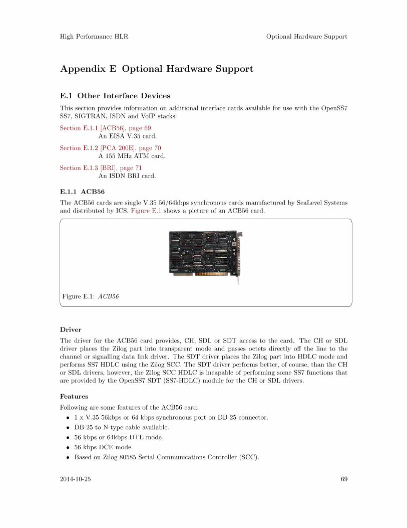
High Performance HLR Optional Hardware Support
Appendix E Optional Hardware Support
E.1 Other Interface Devices
This section provides information on additional interface cards available for use with the OpenSS7SS7, SIGTRAN, ISDN and VoIP stacks:
Section E.1.1 [ACB56], page 69An EISA V.35 card.
Section E.1.2 [PCA 200E], page 70A 155 MHz ATM card.
Section E.1.3 [BRI], page 71An ISDN BRI card.
E.1.1 ACB56
The ACB56 cards are single V.35 56/64kbps synchronous cards manufactured by SeaLevel Systemsand distributed by ICS. Figure E.1 shows a picture of an ACB56 card.� �
Figure E.1: ACB56 Driver
The driver for the ACB56 card provides, CH, SDL or SDT access to the card. The CH or SDLdriver places the Zilog part into transparent mode and passes octets directly off the line to thechannel or signalling data link driver. The SDT driver places the Zilog part into HDLC mode andperforms SS7 HDLC using the Zilog SCC. The SDT driver performs better, of course, than the CHor SDL drivers, however, the Zilog SCC HDLC is incapable of performing some SS7 functions thatare provided by the OpenSS7 SDT (SS7-HDLC) module for the CH or SDL drivers.
Features
Following are some features of the ACB56 card:
• 1 x V.35 56kbps or 64 kbps synchronous port on DB-25 connector.
• DB-25 to N-type cable available.
• 56 kbps or 64kbps DTE mode.
• 56 kbps DCE mode.
• Based on Zilog 80585 Serial Communications Controller (SCC).
2014-10-25 69
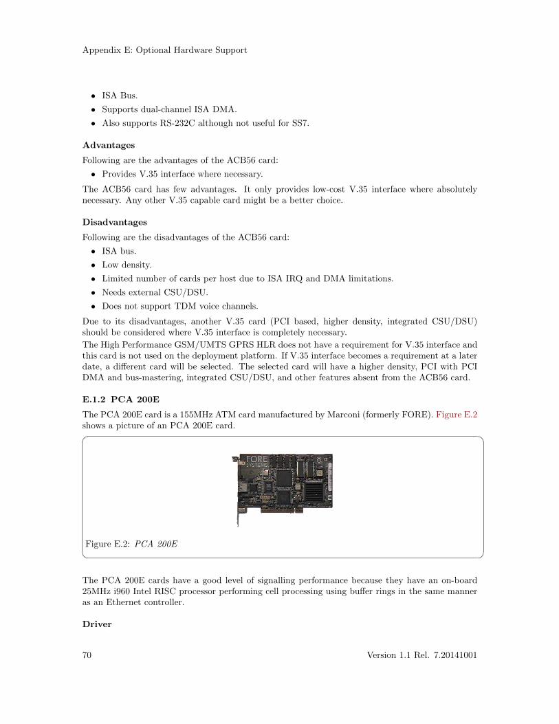
Appendix E: Optional Hardware Support
• ISA Bus.
• Supports dual-channel ISA DMA.
• Also supports RS-232C although not useful for SS7.
Advantages
Following are the advantages of the ACB56 card:
• Provides V.35 interface where necessary.
The ACB56 card has few advantages. It only provides low-cost V.35 interface where absolutelynecessary. Any other V.35 capable card might be a better choice.
Disadvantages
Following are the disadvantages of the ACB56 card:
• ISA bus.
• Low density.
• Limited number of cards per host due to ISA IRQ and DMA limitations.
• Needs external CSU/DSU.
• Does not support TDM voice channels.
Due to its disadvantages, another V.35 card (PCI based, higher density, integrated CSU/DSU)should be considered where V.35 interface is completely necessary.
The High Performance GSM/UMTS GPRS HLR does not have a requirement for V.35 interface andthis card is not used on the deployment platform. If V.35 interface becomes a requirement at a laterdate, a different card will be selected. The selected card will have a higher density, PCI with PCIDMA and bus-mastering, integrated CSU/DSU, and other features absent from the ACB56 card.
E.1.2 PCA 200E
The PCA 200E card is a 155MHz ATM card manufactured by Marconi (formerly FORE). Figure E.2shows a picture of an PCA 200E card.� �
Figure E.2: PCA 200E The PCA 200E cards have a good level of signalling performance because they have an on-board25MHz i960 Intel RISC processor performing cell processing using buffer rings in the same manneras an Ethernet controller.
Driver
70 Version 1.1 Rel. 7.20141001
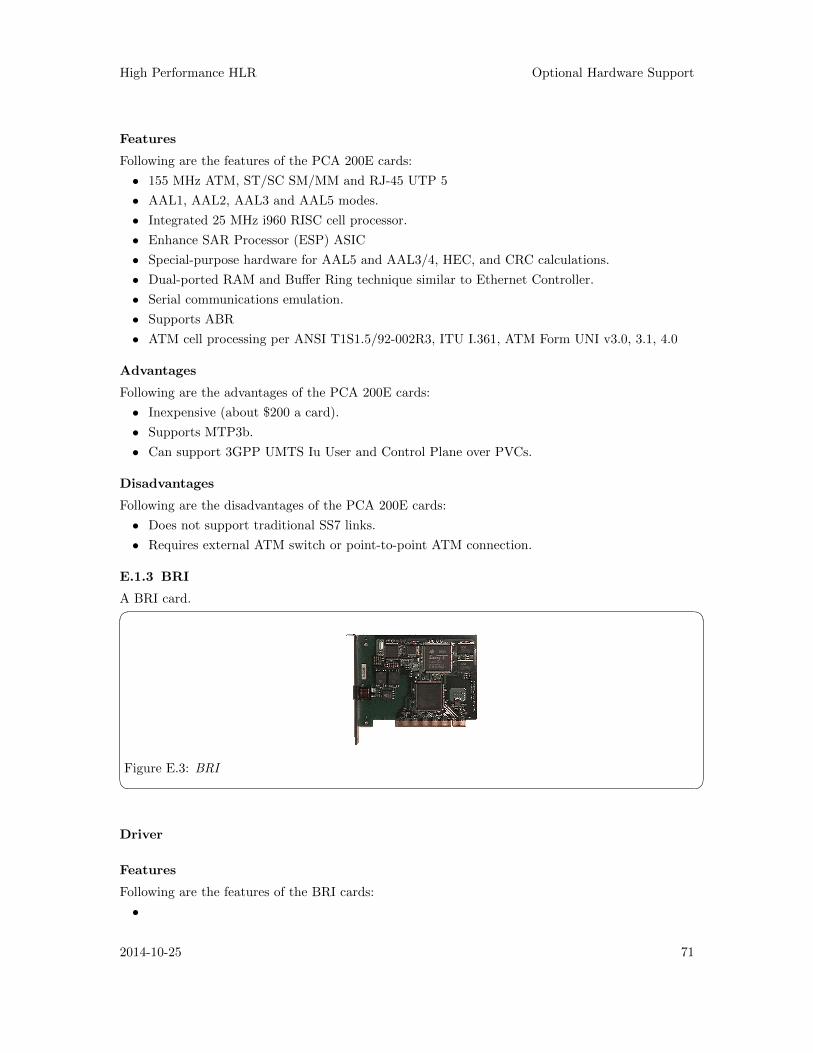
High Performance HLR Optional Hardware Support
Features
Following are the features of the PCA 200E cards:
• 155 MHz ATM, ST/SC SM/MM and RJ-45 UTP 5
• AAL1, AAL2, AAL3 and AAL5 modes.
• Integrated 25 MHz i960 RISC cell processor.
• Enhance SAR Processor (ESP) ASIC
• Special-purpose hardware for AAL5 and AAL3/4, HEC, and CRC calculations.
• Dual-ported RAM and Buffer Ring technique similar to Ethernet Controller.
• Serial communications emulation.
• Supports ABR
• ATM cell processing per ANSI T1S1.5/92-002R3, ITU I.361, ATM Form UNI v3.0, 3.1, 4.0
Advantages
Following are the advantages of the PCA 200E cards:
• Inexpensive (about $200 a card).
• Supports MTP3b.
• Can support 3GPP UMTS Iu User and Control Plane over PVCs.
Disadvantages
Following are the disadvantages of the PCA 200E cards:
• Does not support traditional SS7 links.
• Requires external ATM switch or point-to-point ATM connection.
E.1.3 BRI
A BRI card.� �
Figure E.3: BRI Driver
Features
Following are the features of the BRI cards:
•
2014-10-25 71
Appendix E: Optional Hardware Support
••
Advantages
Following are the advantages of the BRI cards:
•••
Disadvantages
Following are the disadvantages of the BRI cards:
•••
72 Version 1.1 Rel. 7.20141001
High Performance HLR Programmatic Interfaces
Appendix F Programmatic Interfaces
To support a framework for providing transaction products in the UNIX system, an effort is underwayto define service interfaces to map to strategic levels of the Signalling System Number 7 (SS7) model.These service interfaces hide implementation details of a particular service from the consumer ofthe service. This enables system programmers to develop software independent of the particularprotocol that provides a specific service. The interfaces being specified for UNIX System V aredefined within the STREAMS environment. This document specifies a kernel-level interface thatsupports the services of the Transaction Capabilities Application Part for Operation Class 1, 2, 3and 4 services.
This specification applies to System V Release 4.2 ES/MP STREAMS.
F.1 Transaction Component Interface
The transaction component interface defines a message interface to a transaction provider imple-mented under STREAMS.1 A user communicates to a transport provider via a full duplex pathknown as a stream (see Figure F-1 ). This stream provides a mechanism in which messages may bepassed to the transaction provider from the transaction user and visa versa.� �
Figure F-1 - Example of a stream from a user to a transaction provider The STREAMS messages that are used to communicate transaction service primitives between thetransaction user and the transaction provider may have one of the following formats:
1. A M_PROTO message block followed by zero or more M_DATA message blocks. The M_PROTO
message block contains the type of transaction service primitive and all the relevant argumentsassociated with the primitive. The M_DATA blocks contain transaction user data associated withthe transaction service primitive.
F.1.1 Common Transaction Primitives
The following transaction primitives are common to all operation classes:
F.1.1.1 User-Originated Primitives
The following describes the format of the transaction primitives which are generated by the trans-action user.
TC_INFO_REQ - get transaction protocol parameter sizes
This primitive requests the transaction provider to return sizes of all relevant protocol parameters,plus the current state of the provider.2. The format of the message is one M_PCPROTO message block.The format of the M_PCPROTO message block is as follows:
struct TC_info_req {
long PRIM_type; /* always TC_INFO_REQ */
};
F.1.2 TCI Model
1 It is assumed that the reader of this document is familiar with the concept STREAMS.2 The TC_INFO_REQ and TC_INFO_ACK primitives have no effect on the state of the transaction provider and
do not appear in state tables
2014-10-25 73
Appendix F: Programmatic Interfaces
F.1.3 TC Interface Local Management Primitives
The following local management primitives provide local management functions within theSTREAMS environment that are not standardized (implementation dependent). Some of thefunctions are informatively described in ITU-T Recommendation Q.771.
Local Management primitives:
TC_INFO_REQ, TC_INFO_ACK
Information request and acknowledgement. Returns the maximum dialogue SDU sizefor begin, continue and end, the interface SDU size, the maximum address size, maxi-mum options size, service type, current state, provider flags and version.
TC_OPTMGMT_REQ, TC_OPTMGMT_ACK
Options management request and acknowledgement. Negotiates options according tomanagement flags.
TC_BIND_REQ, TC_BIND_ACK
Bind to transport address request and acknowledgement. Contains the transport ad-dress for the bind and the maximum negotiated number of outstanding transactions.
TC_SUBS_BIND_REQ, TC_SUBS_BIND_ACK
Subsequent bind to transport address request and acknowledgement.
TC_SUBS_UNBIND_REQ
Subsequent unbind from transport address request.
TC_UNBIND_REQ
Unbind from transport address request.
TC_OK_ACK Success acknowledgement. Returns the primitive that was successful.
TC_ERROR_ACK
Error acknowledgement. Returns the primitive that was unsuccessful, the error code(transport or UNIX), dialogue identifier and component identifier.
F.1.4 TC Interface Dialogue Handling Primitives
The following dialogue handling primitives correspond to the primitives described in ITU-T Recom-mendation Q.771.
Dialogue Handling primitives:
TC_UNI_REQ, TC_UNI_IND
Unidirectional dialogue request and indication. Includes the source transport address,the destination transport address, associated negotiated options, dialogue identifier andcomponent flags.
TC_BEGIN_REQ, TC_BEGIN_IND, TC_BEGIN_RES, TC_BEGIN_CON
Begin dialogue request, indication, response and confirmation. Includes the sourcetransport address, the destination transport address, associated negotiated options,dialogue identifier and component flags.
TC_CONT_REQ, TC_CONT_IND
Continue dialogue request and indication. Includes the associated negotiated options,dialogue identifier and component flags.
TC_END_REQ, TC_END_IND
End dialogue request and indication. Includes the associated options, dialogue identi-fier, component flags and termination scenario.
74 Version 1.1 Rel. 7.20141001
High Performance HLR Programmatic Interfaces
TC_ABORT_REQ, TC_ABORT_IND
Abort dialogue request and indication. Includes the associated negotiated options,dialogue identifier, abort reason and originator.
TC_NOTICE_IND
Notice indication. Includes the report cause.
F.1.5 TC Interface Component Handling Primitives
The following component handling primitives correspond to the primitives described in ITU-T Rec-ommendation Q.771.
Component Handling primitives:
TC_INVOKE_REQ, TC_INVOKE_IND
Invoke operation request and indication. Includes the dialogue identifier, applicationprotocol class, invoke identifier, linked invoke identifier, invoke operation, segmentationflag, and requested timeout.
TC_RESULT_REQ, TC_RESULT_IND
Return result to operation request and indication. Includes the dialogue identifier,invoke identifier, invoke operation, and segmentation flag.
TC_ERROR_REQ, TC_ERROR_IND
Error of operation request and indication. Includes the dialogue identifier, invokeidentifier, error code and segmentation flag.
TC_REJECT_REQ, TC_REJECT_IND
Reject operation request and indication. Includes the dialogue identifier, invoke iden-tifier, originator, and problem code.
TC_CANCEL_REQ, TC_CANCEL_IND
Cancel component request and indication. Includes the dialogue identifier and invokeidentifier.
F.2 Mobile Application Part Interface
F.2.1 MAP Interface Common Primitives
For a mapping of Common MAP primitives onto TC primitives, see 3GPP TS 29.002 Table 7.5/1and Table 7.5/2.
MAP_OPEN_REQ, MAP_OPEN_IND, MAP_OPEN_RES, MAP_OPEN_CON
Opens a MAP dialogue. Contains application context name, destination address andreference; originating address and reference; specific information, responding address,result, refusal-reason, provider error.
MAP_DELIMITER
Delimits a sequence of components in a MAP dialogue.
MAP_CLOSE_REQ, MAP_CLOSE_IND
Closes a MAP dialogue. Contains release method and specific information.
MAP_ABORT_REQ, MAP_ABORT_IND
Aborts a MAP dialogue. Include user reason, diagnostic information and specific in-formation; or, provider reason and source.
2014-10-25 75
Appendix F: Programmatic Interfaces
MAP_NOTICE
Protocol problem notice. Includes the problem diagnostic.
MAP_SXPORT_REQ, MAP_SXPORT_IND, MAP_SXPORT_RES, MAP_SXPORT_CON
MAP secure transport. Includes operation class, security header, protected payload,user error or provider error.
F.2.2 MAP Interface User-Specific Primitives
For a mapping of User-Specific primitives onto TC primitives, see 3GPP TS 29.002 Table 7.5/3 andTable 7.5/4.
76 Version 1.1 Rel. 7.20141001
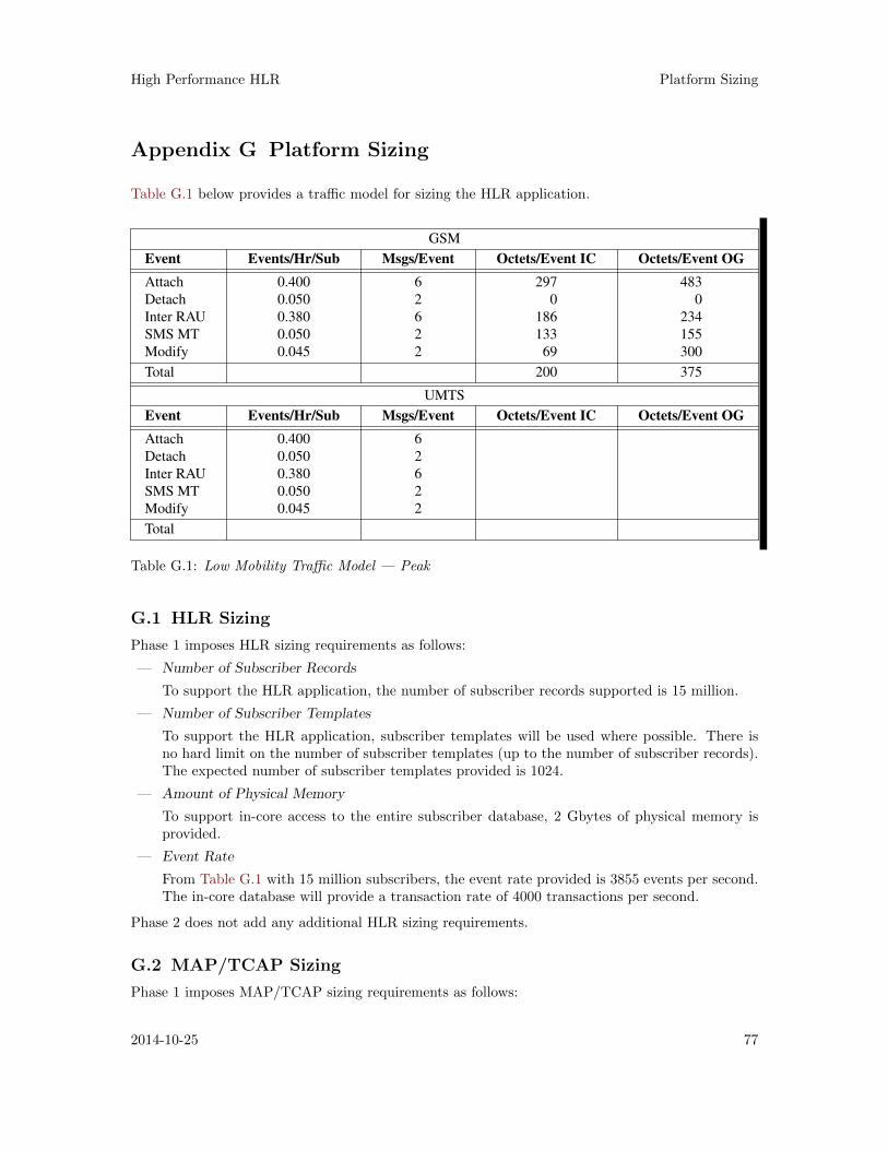
High Performance HLR Platform Sizing
Appendix G Platform Sizing
Table G.1 below provides a traffic model for sizing the HLR application.
GSM
Event Events/Hr/Sub Msgs/Event Octets/Event IC Octets/Event OG
Attach 0.400 6 297 483
Detach 0.050 2 0 0
Inter RAU 0.380 6 186 234
SMS MT 0.050 2 133 155
Modify 0.045 2 69 300
Total 200 375
UMTS
Event Events/Hr/Sub Msgs/Event Octets/Event IC Octets/Event OG
Attach 0.400 6
Detach 0.050 2
Inter RAU 0.380 6
SMS MT 0.050 2
Modify 0.045 2
Total
Table G.1: Low Mobility Traffic Model — Peak
G.1 HLR Sizing
Phase 1 imposes HLR sizing requirements as follows:
— Number of Subscriber Records
To support the HLR application, the number of subscriber records supported is 15 million.
— Number of Subscriber Templates
To support the HLR application, subscriber templates will be used where possible. There isno hard limit on the number of subscriber templates (up to the number of subscriber records).The expected number of subscriber templates provided is 1024.
— Amount of Physical Memory
To support in-core access to the entire subscriber database, 2 Gbytes of physical memory isprovided.
— Event Rate
From Table G.1 with 15 million subscribers, the event rate provided is 3855 events per second.The in-core database will provide a transaction rate of 4000 transactions per second.
Phase 2 does not add any additional HLR sizing requirements.
G.2 MAP/TCAP Sizing
Phase 1 imposes MAP/TCAP sizing requirements as follows:
2014-10-25 77
Appendix G: Platform Sizing
— Transaction Rate
From Table G.1 with 15 million subscribers, the MAP/TCAP transaction rate provided is10,000 MAP/TCAP transactions per second.
— Number of Simultaneous open Transactions
Although the OpenSS7 TCAP component does not have a hard limit on the number of openTCP transactions, the component can be optimized for an expected maximum number of opentransactions. To meet the expected transaction rate and MAP loading, the TCAP componentis optimized for a maximum of 4096 open transactions. If open transactions exceed 4096, per-formance is degraded. Open transactions fewer than 4096 wil have no impact on the platform.
G.3 SCCP Sizing
Phase 1 imposes SCCP sizing requirements as follows:
— Number of Protocol Variants
The OpenSS7 SCCP component provides simultaneous support for ITU-T, ETSI and ANSIprotocol variants in a single protocol module. To support the Phase 1 HLR application, threeprotocol variants will be provided:
1. ITU-T SCCP Q.713 1988/93
2. ETSI SCCP Q.713 1988/93
3. ANSI T1.112/1996
— SCCP Routing
Although the OpenSS7 SCCP component supports a wide range of routing, including localGTT, to meet the HLR application requirements, routing will be performed on PC only.
— Number of Local Subsystems
Although there is no hard limit on the number of local subsystems that can be supported bythe OpenSS7 SCCP protocol component, to support the HLR application, two local subsystemsare provided:
1. One HLR subsystem is provided associated with an ITU-T/ETSI point code in the ITU-T/ETSI domain.
2. Another HLR subsystem is provided associated with an ANSI point code in the ANSIdomain.
— Number of Remote Signalling Points
Although there is no hard limit on the number of remote signalling points that can be supportedby the OpenSS7 SCCP protocol component, to support the HLR application, six (6) remotesignalling points are provided:
1. One (1) remote signalling point codes for one SGSN in the ITU-T/ETSI domain.
2. One (1) remote signalling point codes for one SGSN in the ANSI domain.
3. One (1) remote signalling point codes for another SGSN in the ITU-T/ETSI domain.
4. One (1) remote signalling point codes for another SGSN in the ANSI domain.
5. One (1) remote signalling point codes for a SMS-IWMSC/GMSC platform in the ITU-T/ETSI domain.
6. One (1) remote signalling point codes for a SMS-IWMSC/GMSC platform in the ANSIdomain.
78 Version 1.1 Rel. 7.20141001
High Performance HLR Platform Sizing
— Number of Remote Subsystems
Although there is no hard limit on the number of remote subsystems that can be supportedby the OpenSS7 SCCP protocol component, to support the HLR application, six (6) remotesubsystems are provided:
1. One (1) remote SGSN subsystems for one SGSN in the ITU-T/ETSI domain.
2. One (1) remote SGSN subsystems for one SGSN in the ANSI domain.
3. One (1) remote SGSN subsystems for another SGSN in the ITU-T/ETSI domain.
4. One (1) remote SGSN subsystems for another SGSN in the ANSI domain.
5. One (1) remote MSC subsystems for a SMS-IWMSC/GMSC platform in the ITU-T/ETSIdomain.
6. One (1) remote MSC subsystems for a SMS-IWMSC/GMSC platform in the ANSI domain.
Phase 2 does not add any additional MAP/TCAP sizing requirements.
G.4 MTP Sizing
Phase 1 imposes MTP Level 3 sizing requirements as follows:
— Number of Protocol Variants
The OpenSS7 MTP component provides simutaneous support for ITU-T, ETSI and ANSIprotocol variants in a single protocol module. To support the Phase 1 HLR application, threeprotocol variants will be provided:
1. ITU-T MTP Q.703/Q.704 1988/93
2. ETSI MTP Q.703/Q.704 1988/93
3. ANSI MTP T1.111/1996
— Number of Signalling Points
Although there is no hard limit on the number of local signalling points that can be supportedby the OpenSS7 MTP protocol component, to support the HLR application, two (2) localsignalling points are provided:
1. One local signalling point in the ITU-T/ETSI domain.
2. One local signalling point in the ANSI domain.
— Number of Point Codes
Although there is no hard limit on the number of signalling point codes per local signallingpoint that can be supported by the OpenSS7 MTP protocol component, to support the HLRapplication, two (2) signalling point codes are provided:
1. One signalling point code in the ITU-T/ETSI domain.
2. One signalling point code in the ANSI domain.
— Number of Route Sets
Although there is no hard limit on the number of remote signalling points (routesets) that canbe supported by the OpenSS7 MTP protocol component, to support the HLR application, six(10) routesets are provided:
1. One (1) routeset for one SGSN in the ITU-T/ETSI domain.
2. One (1) routeset for one SGSN in the ANSI domain.
3. One (1) routeset for another SGSN in the ITU-T/ETSI domain.
4. One (1) routeset for another SGSN in the ANSI domain.
2014-10-25 79
Appendix G: Platform Sizing
5. One (1) routeset for an SMS-IWMSC/GMSC in the ITU-T/ETSI domain.
6. One (1) routeset for an SMS-IWMSC/GMSC in the ANSI domain.
7. Two (2) routesets, one for each mated pair of STPs in the ITU-T/ETSI domain.
8. Two (2) routesets, one for each mated pair of STPs in the ANSI domain.
— Number of Signalling Link Sets
Although there is no hard limit on the number of signalling link sets that can be supported bythe OpenSS78 MTP protocol component, to support the HLR application, two (2) combinedlinksets for a total of four (4) linksets are provided:
1. One (1) combined A-linkset or two (2) A-linksets, one for each mated pair of STPs in theITU-T/ETSI domain.
2. One (1) combined A-linkset or two (2) A-linksets, one for each mated pair of STPs in theANSI domain.
— Number of Signalling Links
Table G.1 provides a traffic model for the required number of signalling links. Worst casetraffic at 15 million subscribers is as follows: 375 octets per subscriber per hour, or 12.5 Mbpsof signalling links. This will require 195 low speed signalling links, or 6.3 Q.703 Annex Bhigh-speed signalling links.
To support the HLR application, signalling links will be provided as follows:
– Eight high-speed (2.048 Mbps) signalling links (E1), alternately in the ITU-T/ETSI do-main or in the ANSI domain.
– Because the number of low-speed signalling links would far exceed the ANSI maximum of32, low-speed signalling links cannot be used for 15 million subscriber tests.
— Numebr of Interface Cards
To support the SS7 signalling links will require:
– Two E400P-SS7 card; or,
– Two TE410-SS7 card; or,
– Two A104c card; or,
– Two PCI 384 card.
Phase 2 imposes SCCP sizing requirements as follows:
— SCCP Protocol Variants
The OpenSS7 SCCP component provides simultaneous support for ITU-T, ETSI and ANSIprotocol variants in a single protocol module, and is unaffected by whether the underlyingmessage transfer part is SS7 MTP Level 3 or M3UA.
— SCCP Routing
Phase 2 does not impose any new SCCP routing requirements and routing will still be performedon PC only.
— Number of Local Subsystems
To support M3UA, two additional subsystems are provided:
1. One HLR subsystem for the ITU-T M3UA ASP.
2. Another HLR subsystem for the ANSI M3UA ASP.
— Number of Remote Signalling Points
Phase 2 does not impose any new requirements on the number of remote signalling points.
— Number of Remote Subsystems
Phase 2 does not impose any new requirements on the number of remote signalling subsystems.
80 Version 1.1 Rel. 7.20141001
High Performance HLR Platform Sizing
G.5 M3UA Sizing
Phase 2 adds requirements for M3UA sizing as follows:
— Number of Protocol Variants
The OpenSS7 M3UA component provides simultaneous support for ITU-T, ETSI and ANSIprotocol variants in a single protocol module. To support the Phase 1 HLR application, threeprotocol variants will be provided:
1. ITU-T MTP Q.703/Q.704 1988/93
2. ETSI MTP Q.703/Q.704 1988/93
3. ANSI MTP T1.111/1996
These protocol variants will be provided in two (2) Network Appearances:
1. One network appearance in the ITU-T/ETSI domain.
2. One network appearance in the ANSI domain.
— Number of Signalling Points
Phase 2 adds the requirement for two (2) additional signalling points:
1. One local signalling point in the ITU-T/ETSI domain.
2. One local signalling point in the ANSI domain.
— Number of Point Codes
Phase 2 adds the requirement for two (2) additional signalling point codes:
1. One signalling point code in the ITU-T/ETSI domain.
2. One signalling point code in the ANSI domain.
— Number of Application Server Processes
Provision for 1 Application Server Process. The HLR will represent a single Application ServerProcess within the M3UA domain.
— Number of Application Servers
Provision for 2 M3UA Application Servers:
1. One M3UA ASP is provisioned on the HLR within an ITU-T/ETSI network appearancerequiring 1 ITU-T SS7 Signalling Point Code. This ASP utilizes a Routing Key thatconsists of the ITU-T Network Appearance, ITU-T DPC, and SI value for SCCP (3).
2. Another M3UA ASP is provisioned on the HLR within an ANSI network appearancerequiring 1 ANSI SS7 Signalling Point Code. This ASP utilizes a Routing Key thatconsists of the ANSI Network Appearance, ANSI DPC, and SI value for SCCP (3).
Each ASP is an Override AS that has only one active ASP within the AS.
G.6 SCTP Sizing
Phase 2 adds requirement for SCTP sizing as follows:
— Number of Associations
Although there is no hard limit to the number of SCTP associations that can be supported bythe OpenSS7 SCTP component, to meet the HLR requirements, two (2) associations will beprovided:
1. One association between the HLR and one SG acting as an STP mated pair.
2. One association between the HLR and another SG acting as an STP mated pair.
These two associations will each support the two Application Servers listed above under M3UAsizing.
2014-10-25 81
Appendix G: Platform Sizing
G.7 IP/Ethernet Sizing
Phase 2 adds requirement for IP/Ethernet sizing as follows:
— IP Addresses
Two additional IP addresses and interfaces will be provided to accommodate SCTP multihomedassociations.
— Ethernet Interfaces
Two additional Ethernet 100baseT NICs will be provided to accommodate M3UA traffic. Be-cause worst case traffic is estimated per Table G.1 at 15 millions subscribers at 25 Mbps, theseadditional NICs should accommodate full M3UA traffic.
— Ethernet Switch
A 100baseT Layer 2 switch is provided to ensure that M3UA/SCTP traffic is not hubbed.
82 Version 1.1 Rel. 7.20141001
High Performance HLR Index
Index
AA101c . . . . . . . . . . . . . . . . . . . . . . . . . . . . . . . . . . . . . . . . . 47A102c . . . . . . . . . . . . . . . . . . . . . . . . . . . . . . . . . . . . . . . . . 47A104c . . . . . . . . . . . . . . . . . . . . . . . . . . . . . . . . . . . . . . . . . 47ACB56 . . . . . . . . . . . . . . . . . . . . . . . . . . . . . . . . . . . . . . . . 69Application architecture . . . . . . . . . . . . . . . . . . . . . . . 11Application requirements . . . . . . . . . . . . . . . . . . . . . . 11Attach transaction flow . . . . . . . . . . . . . . . . . . . . . . . . 14Authentication transaction flow . . . . . . . . . . . . . . . . 16
BBRI . . . . . . . . . . . . . . . . . . . . . . . . . . . . . . . . . . . . . . . . . . . 71
CC Interface . . . . . . . . . . . . . . . . . . . . . . . . . . . . . . . . . . . . 20carrier grade . . . . . . . . . . . . . . . . . . . . . . . . . . . . . . . . . . . 13Comet framer . . . . . . . . . . . . . . . . . . . . . . . . . . . . . . . . . 48Consulting . . . . . . . . . . . . . . . . . . . . . . . . . . . . . . . . . . . . 49Cost . . . . . . . . . . . . . . . . . . . . . . . . . . . . . . . . . . . . . . . . . . . 53
DD Interface . . . . . . . . . . . . . . . . . . . . . . . . . . . . . . . . . . . . 21Dallas framer . . . . . . . . . . . . . . . . . . . . . . . . . . . . . . . . . . 44Debian . . . . . . . . . . . . . . . . . . . . . . . . . . . . . . . . . . . . . . . . 67Delete subscriber data transaction flow . . . . . . . . . 17Detach transaction flow . . . . . . . . . . . . . . . . . . . . . . . . 15Document abstract . . . . . . . . . . . . . . . . . . . . . . . . . . . . . 3Document audience . . . . . . . . . . . . . . . . . . . . . . . . . . . . . 3Document disclaimer . . . . . . . . . . . . . . . . . . . . . . . . . . . 4Document information . . . . . . . . . . . . . . . . . . . . . . . . . . 3Document intent . . . . . . . . . . . . . . . . . . . . . . . . . . . . . . . . 3Document objective . . . . . . . . . . . . . . . . . . . . . . . . . . . . . 3Document organization . . . . . . . . . . . . . . . . . . . . . . . . . 4Document revisions . . . . . . . . . . . . . . . . . . . . . . . . . . . . . 3
EE400P-SS7 . . . . . . . . . . . . . . . . . . . . . . . . . 19, 36, 43, 44
FFedora . . . . . . . . . . . . . . . . . . . . . . . . . . . . . . . . . . . . . . . . 67Ferry clip testing . . . . . . . . . . . . . . . . . . . . . . . . . . . . . . 55
GGb Interface . . . . . . . . . . . . . . . . . . . . . . . . . . . . . . . . . . . 59Gc Interface . . . . . . . . . . . . . . . . . . . . . . . . . . . . . . . . . . . 22Gd Interface . . . . . . . . . . . . . . . . . . . . . . . . . . . . . . . . . . . 60
Ge Interface . . . . . . . . . . . . . . . . . . . . . . . . . . . . . . . . . . . 61Gf Interface . . . . . . . . . . . . . . . . . . . . . . . . . . . . . . . . . . . 61Gn Interface . . . . . . . . . . . . . . . . . . . . . . . . . . . . . . . . . . . 62Gp Interface . . . . . . . . . . . . . . . . . . . . . . . . . . . . . . . . . . . 62Gr Interface . . . . . . . . . . . . . . . . . . . . . . . . . . . . . . . . . . . 22Gs Interface . . . . . . . . . . . . . . . . . . . . . . . . . . . . . . . . . . . 63
HHardware . . . . . . . . . . . . . . . . . . . . . . . . . . . . . . . . . . 43, 49Hardware architecture . . . . . . . . . . . . . . . . . . . . . . . . . 43High performance GSM/UMTS GPRS HLR . . . . . 7High Performance HLR 3GPP TS 23.060 GPRS
Application . . . . . . . . . . . . . . . . . . . . . . . . . . . . . . . 29High Performance HLR 3GPP TS 29.002 Mobile
Application Part Application . . . . . . . . . . . . . . 30HLR implementation for testing . . . . . . . . . . . . . . . 12HLR reference interfaces . . . . . . . . . . . . . . . . . . . . . . . 19HLR Sizing . . . . . . . . . . . . . . . . . . . . . . . . . . . . . . . . . . . . 77
IInsert subscriber data transaction flow . . . . . . . . . 16Interface devices . . . . . . . . . . . . . . . . . . . . . . . . . . . . . . . 44Introduction . . . . . . . . . . . . . . . . . . . . . . . . . . . . . . . . . . . . 7IP/Ethernet Sizing . . . . . . . . . . . . . . . . . . . . . . . . . . . . 82Iu Interface . . . . . . . . . . . . . . . . . . . . . . . . . . . . . . . . . . . . 58
LLinux Fast-STREAMS . . . . . . . . . . . . . . . . . . . . . 43, 49Linux Fast-STREAMS (LfS) . . . . . . . . . . . . . . . . . . . 67Linux operating system . . . . . . . . . . . . . . . . . . . . . . . . 39Logistics . . . . . . . . . . . . . . . . . . . . . . . . . . . . . . . . . . . . . . 49
MM2UA . . . . . . . . . . . . . . . . . . . . . . . . . . . . . . . . . . . . . . . . 65M3UA . . . . . . . . 11, 19, 20, 21, 22, 24, 33, 36, 41, 43M3UA Sizing . . . . . . . . . . . . . . . . . . . . . . . . . . . . . . . . . . 81MAP 3GPP TS 29.002 Mobile Application Part
(MAP) Driver . . . . . . . . . . . . . . . . . . . . . . . . . . . . . 31MAP Interface Common Primitives . . . . . . . . . . . . 75MAP Interface User-Specific Primitives . . . . . . . . 76MAP/TCAP Sizing . . . . . . . . . . . . . . . . . . . . . . . . . . . . 77Message Transfer Part (MTP) Driver . . . . . . . . . . 34Mobile application part interface . . . . . . . . . . . . . . . 75Mobile terminated SM transaction flow . . . . . . . . 17MTP Level 2 User Adaptation Layer (M2UA)
Driver . . . . . . . . . . . . . . . . . . . . . . . . . . . . . . . . . . . . 65MTP Level 3 Broadband (MTP3b) Module . . . . 65
2014-10-25 83
Index
MTP Level 3 User Adaptation Layer (M3UA)Driver . . . . . . . . . . . . . . . . . . . . . . . . . . . . . . . . . . . . 36
MTP Sizing . . . . . . . . . . . . . . . . . . . . . . . . . . . . . . . . . . . 79MTP3b . . . . . . . . . . . . . . . . . . . . . . . . . . . . . . . . . . . . . . . 65
NNetwork architecture . . . . . . . . . . . . . . . . . . . . . . . . . . 19
OOpenSS7 SS7 and SIGTRAN stack . . . . . . . . . . . . 39Operating system options . . . . . . . . . . . . . . . . . . . . . . 67Other Interface Cards . . . . . . . . . . . . . . . . . . . . . . . . . 48Other interface devices . . . . . . . . . . . . . . . . . . . . . . . . 69Other interfaces . . . . . . . . . . . . . . . . . . . . . . . . . . . . . . . 24Other protocol components . . . . . . . . . . . . . . . . . . . . 65Other solution architecture . . . . . . . . . . . . . . . . . . . . 55
PPCA 200E . . . . . . . . . . . . . . . . . . . . . . . . . . . . . . . . . . . . . 70Platform architecture . . . . . . . . . . . . . . . . . . . . . . . . . . 27Platform sizing . . . . . . . . . . . . . . . . . . . . . . . . . . . . . . . . 77PMC Sierra framer . . . . . . . . . . . . . . . . . . . . . . . . . . . . 46Project drivers . . . . . . . . . . . . . . . . . . . . . . . . . . . . . . . . . . 7Project gates . . . . . . . . . . . . . . . . . . . . . . . . . . . . . . . . . . . 8Project phase 1, requirements . . . . . . . . . . . . . . . . . . 11Project phase 2, requirements . . . . . . . . . . . . . . . . . . 11Project phase 3, requirements . . . . . . . . . . . . . . . . . . 11Project phase 4, requirements . . . . . . . . . . . . . . . . . . 11Project phase 5, requirements . . . . . . . . . . . . . . . . . . 11Project phases . . . . . . . . . . . . . . . . . . . . . . . . . . . . . . . . . . 7Protocol architecture . . . . . . . . . . . . . . . . . . . . . . . . . . 29Protocol components . . . . . . . . . . . . . . . . . . . . . . . . . . 29Purge transaction flow . . . . . . . . . . . . . . . . . . . . . . . . . 15
QQ.703 Annex B . . . . . . . . . . . . . . . . . . . . . 19, 24, 36, 37
RRedHat . . . . . . . . . . . . . . . . . . . . . . . . . . . . . . . . . . . . . . . 67
SSCCP Sizing . . . . . . . . . . . . . . . . . . . . . . . . . . . . . . . . . . 78SCCP User Adaptation Layer (SUA) Driver . . . . 65Schedule . . . . . . . . . . . . . . . . . . . . . . . . . . . . . . . . . . . . . . 49Scope . . . . . . . . . . . . . . . . . . . . . . . . . . . . . . . . . . . . . . . . . . 7SCTP . . . . . . . . . . . . . . . . . . . . . . . 19, 24, 32, 36, 38, 65SCTP Sizing . . . . . . . . . . . . . . . . . . . . . . . . . . . . . . . . . . 81Service Specific Connection Oriented Protocol
(SSCOP) Driver . . . . . . . . . . . . . . . . . . . . . . . . . . 65SGSN reference interfaces . . . . . . . . . . . . . . . . . . . . . . 57Signalling Connection Control Part (SCCP) Driver
. . . . . . . . . . . . . . . . . . . . . . . . . . . . . . . . . . . . . . . . . . . 32Signalling Data Terminal (SDT) Module . . . . . . . 37Signalling Link (SL) Module . . . . . . . . . . . . . . . . . . . 36Sizing considerations . . . . . . . . . . . . . . . . . . . . . . . . . . . 49Software . . . . . . . . . . . . . . . . . . . . . . . . . . . . . . . . . . . . . . . 49Software architecture . . . . . . . . . . . . . . . . . . . . . . . . . . 39Solution architecture . . . . . . . . . . . . . . . . . . . . . . . . . . 11SS7 Stack Manager . . . . . . . . . . . . . . . . . . . . . . . . . . . . 30SSCOP . . . . . . . . . . . . . . . . . . . . . . . . . . . . . . . . . . . . . . . . 65Stream Control Transmission Protocol (SCTP)
Driver . . . . . . . . . . . . . . . . . . . . . . . . . . . . . . . . . . . . 38STREAMS facility . . . . . . . . . . . . . . . . . . . . . . . . . . . . . 39STREAMS options . . . . . . . . . . . . . . . . . . . . . . . . . . . . 67SUA . . . . . . . . . . . . . . . . . . . . . . . . . . . . . . . . . . . . . . . . . . 65SuSE . . . . . . . . . . . . . . . . . . . . . . . . . . . . . . . . . . . . . . . . . . 67System architecture . . . . . . . . . . . . . . . . . . . . . . . . . . . . 25
TT400P-SS7 . . . . . . . . . . . . . . . . . . . . . . . . . . . . . . . . . . . . 44TC Interface Component Handling Primitives . . 75TC Interface Dialogue Handling Primitives . . . . . 74TC Interface Local Management Primitives . . . . 74TCI Model . . . . . . . . . . . . . . . . . . . . . . . . . . . . . . . . . . . . 73TE405-SS7 . . . . . . . . . . . . . . . . . . . . . . . . . . . . . . . . . . . . 45TE410-SS7 . . . . . . . . . . . . . . . . . . . . . . . . . . . . . . . . . . . . 45Transaction Capabilities Application Part (TCAP)
Driver . . . . . . . . . . . . . . . . . . . . . . . . . . . . . . . . . . . . 31Transaction component interface . . . . . . . . . . . . . . . 73Transaction flows . . . . . . . . . . . . . . . . . . . . . . . . . . . . . . 14
XXilinx . . . . . . . . . . . . . . . . . . . . . . . . . . . . . . . . . . 44, 46, 48
84 Version 1.1 Rel. 7.20141001