high-energy nd:glass laser facility for collisionless...
TRANSCRIPT
2012 JINST 7 P03010
PUBLISHED BY IOP PUBLISHING FOR SISSA MEDIALAB
RECEIVED: February 7, 2012
ACCEPTED: February 27, 2012
PUBLISHED: March 23, 2012
High-energy Nd:glass laser facility for collisionless
laboratory astrophysics
C. Niemann,a,1 C.G. Constantin,a D.B. Schaeffer,a A. Tauschwitz,b T. Weiland,c
Z. Lucky,a W. Gekelman,a E.T. Eversona and D. Winsked
aDepartment of Physics and Astronomy, University of California Los Angeles,
1040 Veteran Ave., Los Angeles, CA 90095, U.S.A.bGesellschaft fuer Schwerionenforschung,
Planckstr. 1, 64291 Darmstadt, GermanycLawrence Livermore National Laboratory,
7000 East Ave., Livermore, CA 94550, U.S.A.dLos Alamos National Laboratory,
Bikini Atoll Rd., Los Alamos, NM 87545, U.S.A.
E-mail: [email protected]
ABSTRACT: A kilojoule-class laser (Raptor) has recently been activated at the Phoenix-laser-
facility at the University of California Los Angeles (UCLA) for an experimental program on labo-
ratory astrophysics in conjunction with the Large Plasma Device (LAPD). The unique combination
of a high-energy laser system and the 18 meter long, highly-magnetized but current-free plasma
will support a new class of plasma physics experiments, including the first laboratory simulations
of quasi-parallel collisionless shocks, experiments on magnetic reconnection, or advanced laser-
based diagnostics of basic plasmas. Here we present the parameter space accessible with this new
instrument, results from a laser-driven magnetic piston experiment at reduced power, and a detailed
description of the laser system and its performance.
KEYWORDS: Plasma generation (laser-produced, RF, x ray-produced); Pulsed power; Plasma di-
agnostics - probes
1Corresponding author.
c© 2012 IOP Publishing Ltd and Sissa Medialab srl doi:10.1088/1748-0221/7/03/P03010
2012 JINST 7 P03010
Contents
1 Introduction 1
2 Laboratory simulations of collisionless shocks 2
2.1 The physics of heliospheric shocks 2
2.2 Scaling to the laboratory 3
2.3 Collisionless shocks in the LAPD 4
2.4 Initial results and simulations 6
3 High-energy laser system 8
3.1 Laser architecture 9
3.2 Pulsed power 12
3.3 Laser control and diagnostics systems 15
4 Conclusion 16
1 Introduction
Situations where a dense plasma-cloud explodes at high speed into an ionized, magnetized medium
are ubiquitous in space and astrophysical environments. Examples include supernova remnants [1],
coronal mass ejections [2], meteor impacts [3], and man-made explosions in the upper atmo-
sphere [4]. Most of these phenomena launch ”collisionless” shockwaves in the tenuous plasmas,
in the absence of binary collisions. These shocks are mediated by self-generated electromagnetic
fields due to plasma turbulence on scale-lengths far shorter than the classical mean-free-path, and
are important mechanisms for decelerating super-Alfvenic flows while converting ram-pressure
into thermal energy [5]. The physics that determines the structure and evolution of a shock in space
depends strongly on the geometry, i.e. the shock-normal with respect to the magnetic field. While
quasi-perpendicular shocks are based on fast magnetosonic modes, quasi-parallel shocks are based
on whistler waves or ion waves. The physics of quasi-parallel shocks is much more complex and
not as well understood [6].
Laboratory experiments can contribute to our understanding of extraterrestrial shocks by doing
well scaled physics despite orders of magnitude differences in temporal and spatial scales [7–10].
In particular, the formation of a shock, the nature of micro-instabilities, and the transport of debris
ions across the shock ramp can only be limitedly studied in space. In the late sixties and early seven-
ties, before the advent of spacecraft for in situ measurements of the Earth’s bow shock [11], much
of our knowledge of collisionless shocks was derived from laboratory experiments on magnetic
pinches [12]. These experiments were based on current-driven magnetic pistons and were limited
to strictly perpendicular geometries. Laser-driven pistons, on the other hand, are intrinsically more
flexible and could potentially be used to design shock experiments in arbitrary geometries. While
– 1 –
2012 JINST 7 P03010
attempts have been made to simulate collisionless shocks using lasers to produce a miniature ex-
ploding debris cloud [7, 10, 13–15], such experiments were generally too small and short-lived,
resulting in sub-Alfvenic explosion velocities or insufficient magnetization.
A high-energy Nd:glass laser system has recently been commissioned at UCLA to support
a new class of experiments on collisionless shocks in a large, magnetized plasma produced by
the Large Plasma Device (LAPD) [16]. The new laser system can deliver an energy up to 500
J in a 25 ns pulse at 1053 nm to a target inside the preformed plasma, and potentially up to 1
kJ at longer pulses (∼0.1-1 µs). The ambient plasma (2 × 1012 cm−3, 5 eV) is homogeneous,
highly reproducible, quiescent, current-free, and large enough (18 m x 0.6 m) to support Alfven
waves [17]. This unique combination of super-Alfvenic, exploding laser-plasmas and the large,
highly-magnetized ambient plasma will support novel experiments on collisionless laboratory as-
trophysics, including the very first experiments on quasi-parallel shocks.
Similarly, the new facility will support experiments on a number of related topics, including
laboratory simulations of magnetized jets [18, 19], magnetic reconnection [20], and the genera-
tion of highly-nonlinear Alfven waves [21]. The energy in the exploding debris-plasma is initially
much higher than the energy stored in the ambient plasma. At these conditions the blow-off plume
can live for hundreds of microseconds and expand to sizes of several meters, forming large-scale
structures with complicated three-dimensional magnetic field topologies [22]. The laser can be
frequency-doubled to the green (527 nm, 400 J) to serve as a high-energy probe-beam for Thom-
son scattering in the LAPD. Since scattering measurements are challenging at these low densities
due to the small scattering cross-section, complex low-energy (10 J) multi-passing schemes have
been used in the past to increase the effective energy delivered to the scattering volume [23]. Two-
dimensional imaging scattering measurements of plasma density turbulence in magnetized plasmas
are potentially possible with the new laser for the first time [24–26]. The laser will also support var-
ious high-energy density physics experiments that do not require the magnetized plasma, such as
the development of efficient laser-plasma based x-ray sources [27] and their application to probing
matter under extreme conditions [28–30].
The plan of the paper is as follows. In section 2 we review some of the physics of colli-
sionless shocks (2.1) and discuss in detail how certain aspects can be reproduced in a controlled
laboratory setting (2.2). We present specific point designs for shock experiments in the LAPD at
quasi-perpendicular and quasi-parallel geometry (2.3), and show results from two-dimensional hy-
brid simulations on a quasi-perpendicular shock in the LAPD at the projected parameters (2.4). In
section 2.4 we also show some data from experiments at reduced power and density that reproduce
the basic features of the simulation very well, although in a regime where shocks cannot form.
In section 3 we give a detailed description of the laser system and its performance, including the
optical design (3.1), the pulsed power conditioning (3.2), and the diagnostics and controls (3.3).
Section 4 is a conclusion.
2 Laboratory simulations of collisionless shocks
2.1 The physics of heliospheric shocks
Collisionless shocks, like their collisional counterparts, decelerate a super-magnetosonic flow while
heating and compressing the plasma in the downstream region (i.e. the heated region behind the
– 2 –

2012 JINST 7 P03010
shock). Heliospheric collisionless shocks form in strongly-magnetized plasmas and are mediated
by magnetic reflection [5]. The properties of these shocks depend strongly on the orientation
of the magnetic field upstream (i.e. the shock-normal with respect to the magnetic field ahead
of the shock), and the strength of the shock (i.e. the Alfvenic Mach number MA = vshock/vA,
where vA = B/√
µ0nimi is the Alfven speed, B is the magnetic-flux-density, and ni and mi are
the ion-density and ion-mass, respectively). Quasi-perpendicular shocks have a well-defined ramp
with a thickness around ten collisionless skin-depths (10 c/ωpe, where ωpe = (nee2/(meε0))1/2
is the electron-plasma frequency, ne is the electron density, and c is the speed of light), which
is much smaller than the ion-gyroradius [31]. Inside the shock-ramp, charge separation of the
highly-magnetized electrons and unmagnetized ions leads to a cross-shock potential and an elec-
tron E×B-drift along the shock-surface [32]. The free energy provided by this cross-field current
drives microscopic plasma-instabilities and associated plasma-waves to a level where they begin to
interact back on the particles. These wave-particle interactions give rise to a frictional force that
leads to plasma heating and resistivity on scales much smaller than the classical mean-free-path.
A detailed study of the nature of these instabilities is one of the goals of the experiments proposed
here and can presently be done nowhere else.
In sub-critical shocks (i.e. shocks with MA < Mcrit, where Mcrit is the critical Mach number and
around 3 depending on the conditions) the two most important wave modes and their instabilities
are believed to be the lower-hybrid-drift instability (LHDI) and the modified two-stream instability
(MTSI) [5, 33]. The LHDI arises if the transition layer is comparable to the ion-inertial length
(c/ωpi, where ωpi = (nie2Z2/(miε0))
1/2 is the ion-plasma frequency and Z the ion charge state),
while the MTSI is directly excited by the cross-field current. Both instabilities yield large collision
frequencies on the order of the lower-hybrid frequency ωLH = ωpi/(1+ω2pe/ω
2ce)
1/2 ≈ (ωceωci)1/2,
where ωce = eB/me and ωci = ZeB/mi are the electron- and ion-cyclotron frequencies, respectively.
In stronger shocks (MA > Mcrit) the cross-shock potential becomes large enough that a sig-
nificant fraction of the ions from the unshocked (upstream) region are reflected. In the upstream
region, these reflected ions cause a distinct ”foot” in the magnetic profile ahead of the shock that
has a thickness comparable to the ion-Larmor-radius rL,i [31]. In a quasi-perpendicular shock
the reflected ions gyrate back downstream and create a large energy-anisotropy behind the shock.
Quasi-parallel shocks are much more complicated and not as well understood. According to theory
and measurements in the Earth’s bow-shock, the transition region is much wider and more diffuse,
characterized by an extended foreshock region with large amplitude magnetic pulsations and ener-
getic ions which have leaked upstream [34]. The magnetic field compression across the ramp and
the cross-shock potential are smaller and are believed to vanish in the exactly parallel case [5].
2.2 Scaling to the laboratory
Reproducing these conditions in the laboratory requires a piston that propagates at super-Alfvenic
speed (MA > 1) through a magnetized plasma long enough for magnetohydrodynamic turbulence
to develop and for reflected ions to participate in the evolution of the shock. In other words, the
shock transit time τ = D/vshock through a plasma of length D must exceed the ion-gyroperiod
(τωci > 1), so that instabilities in the lower-hybrid range have sufficient time to grow (ωLH > ωci).
Simultaneously, shocked ions will then have enough time to travel at least one Larmor-radius in
the downstream region. This is equivalent to providing a system size D large enough to fit in a full
– 3 –

2012 JINST 7 P03010
shock-structure (D > rL,i = MA · c/ωpi, where the ion-gryoradius rL,i is comparable to the width of
the foot-region in a quasi-perpendicular shock). In addition, hybrid simulations have shown that
the width of the piston (transverse to the shock normal) must exceed an ion-inertial length (c/ωpi)
for a shock to form [35].
The magnetic field compression factor Bd/Bu across the shock, which describes the jump from
the upstream (Bu) to the downstream (Bd) values, is given by the Rankine-Hugoniot relations [36].
In quasi-perpendicular geometry, the field-jump increases linearly with Mach-number MA for weak
shocks (MA < 3) but stagnates at around Bd/Bu ≈ 4 for stronger shocks (MA > 4). Higher-Mach-
number shocks (up to MA ≈ 4) thus take advantage of the compressed field downstream, which
keeps the Larmor-radius small even though the shock-speed increases. Strong shocks (MA > 4)
require more space to form, since the field-compression ratio stagnates at around 4. Quasi-parallel
shocks form more slowly, on the order of the growth-time of the firehouse instability (τωci >
10) [37], and require more space (D > 10c/ωpi).
Simultaneously, the proton-mean-free-path λpp = 7.0 · 1014v4/ni for binary collisions [38]
must be larger than the size of the experiment λpp ≫ D so that collisionless mechanisms dominate
the evolution of the shock (here v is the proton velocity in 107 cm/s, ni is the plasma-ion density in
cm−3, and λpp is given in cm). In addition, the electron mean-free-path must be sufficiently long
that the magnetohydrodynamic turbulence is not damped by classical collisions. In other words,
the plasma conductivity σ due to electron-ion collisions must be large enough to avoid significant
dissipation due to Joule heating in the shock-transition layer. In a plasma with upstream densities
on the order of 1014 cm−3, this requires temperatures above 1 eV [39]. At these conditions, the
magnetic Reynolds number Rm = σvshockL will be much larger than unity, so that advection is sig-
nificantly more important than diffusion (L is the relevant scale-length, which is the thickness of
the current layer in this case).
A detailed analysis shows that the conditions above can be satisfied simultaneously in a con-
trolled laboratory setting [7]. Previous laboratory experiments on collisionless shocks were con-
ducted mostly on imploding pinches [12], where an axial current through a plasma column is
ramped-up rapidly to drive a cylindrical implosion and a converging perpendicular shock. Such
experimental configurations are limited to exact perpendicular geometries, and severely constrain
studying the formation and separation of the shock from the magnetic piston. Experiments were
also performed with plasma wind tunnels [40] and laser-produced micro-explosions in a preformed
theta-pinch discharge [10], in static gas-fills [41], in photo-ionized plasmas [15], or in a magnetized
laser-plasma plume [42, 43]. More recent work has focused on counterstreaming plasmas [44].
2.3 Collisionless shocks in the LAPD
The facility described here uniquely combines a kilojoule-laser with the LAPD, and will support
a new class of experiments on laser-driven shocks in a large, magnetized plasma. The ambient
plasma is current free, homogeneous, highly-reproducible, and large enough (18 m x 0.6 m diam-
eter) [16] to allow Alfven waves to participate in the evolution of a shock. The flexibility of the
laser-plasma piston will support experiments in a variety of geometries, including quasi-parallel,
oblique, and quasi-perpendicular. Quasi-parallel shocks, in particular, have never been produced
in a controlled laboratory setting. While laser-experiments have been performed previously at the
LAPD at much lower energy (∼ 1 J) [45–48], the explosion velocities were typically sub-Alfvenic,
– 4 –
2012 JINST 7 P03010
or the piston did not propagate far enough for a shock to form. The new laser can deliver three or-
ders of magnitude more energy at higher intensities, and therefore maintain a super-Alfvenic piston
over several meters and relevant scale-lengths (c/ωpi).
In the experiments, a miniature exploding plasma-cloud is produced by irradiating a solid tar-
get embedded in the preformed magnetoplasma with a high-power laser-pulse [49]. Focusing the
beam to a 500 µm spot on a graphite or polyethylene (CH) target inside the magnetized plasma at
an average intensity around 1013 W/cm2 will ablate more than 1017 debris ions at a bulk velocity of
500 km/s [50]. The plasma-plume blows off perpendicularly to the target surface and can be con-
veniently directed at arbitrary angles relative to the external magnetic field by rotating the target.
The ambient plasma is created once a second by an electric discharge between a cathode and an
anode grid on one side of the machine [46], and is maintained for several ms. The plasma column
is formed by impact ionization of a gas-fill in a steady, axial magnetic field up to 1800 G, and the
plasma is current free. On the hydrodynamic time-scales of the laser-plasma the ambient-plasma
is practically stationary. Plasma densities are currently limited to ni = 2× 1012 cm−3 at tempera-
tures of Te=5 eV by the emissivity of the barium oxide coated cathode in the LAPD [16]. A new
lanthanum-hexaboride (LaB6) cathode will be installed in the near future [51] that will create plas-
mas at higher densities in excess of 1013 cm−3, and thus reduce the Alfven speed and ion-inertial
length while increasing the Mach-number.
The experiments proposed here will employ a fast laser-driven magnetic piston to transfer mo-
mentum to the stationary ambient plasma, even in the absence of collisions. Initially, the ratio of the
laser-plasma energy density to magnetic field energy density is β = nkBT/(B2/2µ0) > 1, and the
Larmor radii of the debris-ions is large compared to the size of the plasma-plume. Therefore, the
dynamics of the exploding laser-plasma is only marginally affected by the background magnetic
field. However, the plasma’s finite conductivity and frozen-in magnetic flux lead to an expulsion
and distortion of the magnetic field lines and the creation of a diamagnetic cavity [52]. Laminar
electric fields at the edge of the bubble decelerate the debris ions and accelerate the ambient ions
via Larmor-coupling [1]. The edge of the exploding field-free cavity thus acts as a magnetic piston
that accelerates the ambient plasma to the piston-velocity within one ion-gyroperiod ω−1ci . Initially,
when the laser-plasma is small and dense, additional momentum transfer may occur through clas-
sical binary collisions. Ambient ions, accelerated by the piston to super-Alfvenic velocities and
streaming relative to the stationary ambient ions, can ultimately lead to the formation of a colli-
sionless shock. This proposed laser-bubble piston is significantly more efficient than a piston based
on shock-breakout from the back of a laser-irradiated target suggested elsewhere [7]. The cavity
expands at near constant velocity, until the kinetic energy in the debris plasma Edebris overruns a vol-
ume with an equivalent energy in the magnetic field Em = V ·B2/(2µ0). The magnetic stopping ra-
dius RB can be calculated from a simple energy balance RB =[
3µ0Edebris/(2πB2)]1/3
(1+M2A)−1/3,
where the (1+MA)−1/3 correction term accounts for the Larmor coupling to the ambient ions. The
size of the piston thus increases with the laser energy (RB ∼E1/3
laser), which shows why a high-energy
laser system is required for such experiments.
The point design for an experiment on perpendicular shocks employs a H+ ambient plasma
at 10 eV and densities of 2× 1013 cm−3 in 500 G. The debris-cloud will contain a total kinetic
energy around 50 J (i.e. 10% coupling from the laser to the blow-off), and explode with a bulk
velocity around 500 km/s, corresponding to MA = 2. The maximum diameter of the diamagnetic
– 5 –
2012 JINST 7 P03010
cavity DB = 2RB = 50 cm is comparable to the transverse size of the ambient plasma. The piston
can thus propagate for ten ion-inertial lengths (c/ωpi= 5 cm) or five shocked Larmor-radii in the
downstream region, considering a field compression of Bd/Bu = 2 in accordance with the jump
conditions. Simultaneously, the shock transit time is around τ = 1 µs and several times the ion-
gyroperiod (τωci = 10), so there is enough time for magnetohydrodynamic turbulence to grow.
The mean-free path for a shocked ion moving at the piston velocity (500 km/s) is more than 200
m, and binary collisions are negligible. Super-critical pistons can be produced and maintained over
fewer scale-lengths using heavier gases (e.g. helium) with a smaller Alfven speed (see table 1). For
example, a 500 km/s piston propagating through a He+ plasma at ni = 2×1013 cm−3 in 300 G will
drive an MA = 7 shock over 5 c/ωpi and 3 ion-gyroperiods (τωci = 3).
Experiments in a quasi-parallel geometry will take advantage of the unsurpassed length of
the ambient plasma column (D = 18 m). Previous experiments at lower power and sub-Alfvenic
velocity [53, 54] have shown that the blow-off from a solid target propagates as a high-density
plasma-cloud over distances of several meters through the ambient plasma, when directed along
the field lines. In H+ at ni = 2× 1013 cm−3 and 350 G, the piston can then propagate over more
than 300 c/ωpi. The piston-transit time for a 500 km/s blow-off (MA = 3) is 34 µs and a hundred
gyroperiods (τωci ≈ 100), so there is enough time for firehose-type instabilities to grow.
2.4 Initial results and simulations
We have already demonstrated the laser-bubble magnetic piston in experiments at reduced energy
(20 J) and limited ambient plasma density (2×1012 cm−3). At these conditions, the piston was sub-
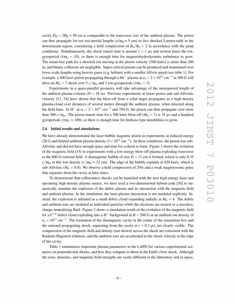
Alfvenic and did not have enough space and time for a shock to form. Figure 1 shows the evolution
of the magnetic field [55] in experiments with a low-energy blow-off plasma exploding transverse
to the 600 G external field. A diamagnetic bubble of size D = 11 cm is formed, which is only 0.35
c/ωpi at this low density (c/ωpi = 32 cm). The edge of the bubble expands at 420 km/s, which is
sub-Alfvenic (MA = 0.8). We observe a field compression of 20% and a weak magnetosonic pulse
that separates from the cavity at later times.
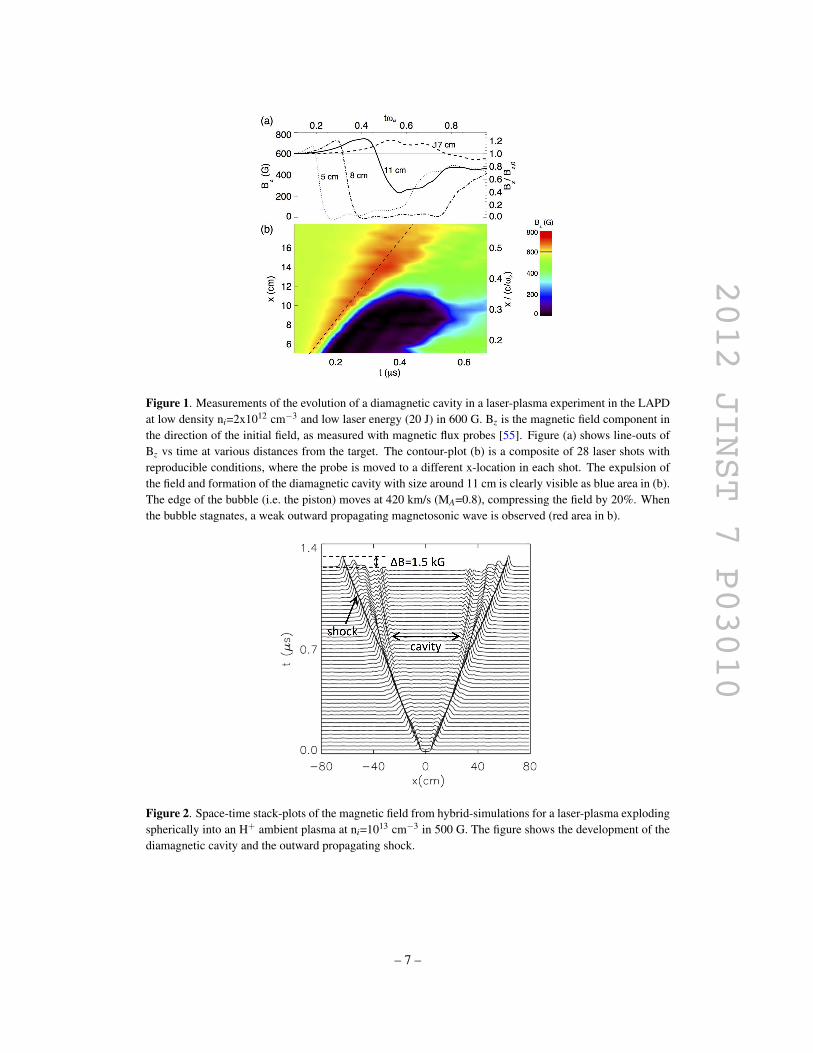
To demonstrate that collisionless shocks can be launched with the new high-energy laser and
upcoming high-density plasma source, we have used a two-dimensional hybrid-code [56] to nu-
merically simulate the explosion of the debris plasma and its interaction with the magnetic field
and ambient plasma. In the simulation, the laser-plasma interaction is not modeled explicitly. In-
stead, the explosion is initiated as a small debris cloud expanding radially at MA = 4. The debris
and ambient ions are modeled as individual particles while the electrons are treated as a massless,
charge-neutralizing fluid. Figure 2 shows a simulation result of the evolution of the magnetic field
for a C+6 debris cloud exploding into a H+ background in B = 500 G at an ambient ion density of
ni = 1013 cm−3. The formation of the diamagnetic cavity in the center of the simulation box and
the outward propagating shock, separating from the cavity at t = 0.3 µs, are clearly visible. The
compression of the magnetic field and density (not shown) across the shock are consistent with the
Rankine-Hugoniot relations, and the ambient ions are accelerated to the shock velocity at the edge
of the cavity.
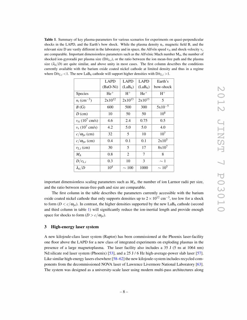
Table 1 summarizes important plasma parameters in the LAPD for various experimental sce-
narios on perpendicular shocks, and how they compare to those in the Earth’s bow shock. Although
the sizes, densities, and magnetic field strengths are vastly different in the laboratory and in space,
– 6 –
2012 JINST 7 P03010
Figure 1. Measurements of the evolution of a diamagnetic cavity in a laser-plasma experiment in the LAPD
at low density ni=2x1012 cm−3 and low laser energy (20 J) in 600 G. Bz is the magnetic field component in
the direction of the initial field, as measured with magnetic flux probes [55]. Figure (a) shows line-outs of
Bz vs time at various distances from the target. The contour-plot (b) is a composite of 28 laser shots with
reproducible conditions, where the probe is moved to a different x-location in each shot. The expulsion of
the field and formation of the diamagnetic cavity with size around 11 cm is clearly visible as blue area in (b).
The edge of the bubble (i.e. the piston) moves at 420 km/s (MA=0.8), compressing the field by 20%. When
the bubble stagnates, a weak outward propagating magnetosonic wave is observed (red area in b).
Figure 2. Space-time stack-plots of the magnetic field from hybrid-simulations for a laser-plasma exploding
spherically into an H+ ambient plasma at ni=1013 cm−3 in 500 G. The figure shows the development of the
diamagnetic cavity and the outward propagating shock.
– 7 –
2012 JINST 7 P03010
Table 1. Summary of key plasma-parameters for various scenarios for experiments on quasi-perpendicular
shocks in the LAPD, and the Earth’s bow shock. While the plasma density ni, magnetic field B, and the
relevant size D are vastly different in the laboratory and in space, the Alfven speed vA and shock-velocity vs
are comparable. Important dimensionless parameters such as the Alfvenic Mach number MA, the number of
shocked ion-gyroradii per plasma size (D/rL,i), or the ratio between the ion mean-free path and the plasma
size (λii/D) are quite similar, and above unity in most cases. The first column describes the conditions
currently available with the barium oxide coated nickel cathode at limited density and thus in a regime
where D/rL,i <1. The new LaB6 cathode will support higher densities with D/rL,i >1.
LAPD LAPD LAPD Earth’s
(BaO-Ni) (LaB6) (LaB6) bow-shock
Species He+ H+ He+ H+
ni (cm−3) 2x10¹² 2x10¹³ 2x10¹³ 5
B (G) 600 500 300 5x10⁻⁵
D (cm) 10 50 50 108
vA (107 cm/s) 4.6 2.4 0.75 0.5
vs (107 cm/s) 4.2 5.0 5.0 4.0
c/ωpi (cm) 32 5 10 107
c/ωpe (cm) 0.4 0.1 0.1 2x10⁵
rL,i (cm) 30 5 17 8x10⁷
MA 0.8 2 7 8
D/rL,i 0.3 10 3 ∼ 1
λii/D 104∼ 100 1000 ∼ 105
important dimensionless scaling parameters such as MA, the number of ion Larmor radii per size,
and the ratio between mean-free-path and size are comparable.
The first column in the table describes the parameters currently accessible with the barium
oxide coated nickel cathode that only supports densities up to 2×1012 cm−3, too low for a shock
to form (D < c/ωpi). In contrast, the higher densities supported by the new LaB6 cathode (second
and third column in table 1) will significantly reduce the ion-inertial length and provide enough
space for shocks to form (D > c/ωpi).
3 High-energy laser system
A new kilojoule-class laser system (Raptor) has been commissioned at the Phoenix laser-facility
one floor above the LAPD for a new class of integrated experiments on exploding plasmas in the
presence of a large magnetoplasma. The laser facility also includes a 35 J (5 ns at 1064 nm)
Nd:silicate rod laser system (Phoenix) [53], and a 25 J / 6 Hz high-average-power slab laser [57].
Like similar high-energy lasers elsewhere [58–62] the new kilojoule-system includes recycled com-
ponents from the decommissioned NOVA laser of Lawrence Livermore National Laboratory [63].
The system was designed as a university-scale laser using modern multi-pass architectures along
– 8 –
2012 JINST 7 P03010
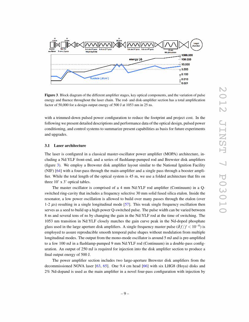
Figure 3. Block diagram of the different amplifier stages, key optical components, and the variation of pulse
energy and fluence throughout the laser chain. The rod- and disk-amplifier section has a total amplification
factor of 50,000 for a design output energy of 500 J at 1053 nm in 25 ns.
with a trimmed-down pulsed power configuration to reduce the footprint and project cost. In the
following we present detailed descriptions and performance data of the optical design, pulsed power
conditioning, and control systems to summarize present capabilities as basis for future experiments
and upgrades.
3.1 Laser architecture
The laser is configured in a classical master-oscillator power amplifier (MOPA) architecture, in-
cluding a Nd:YLF front-end, and a series of flashlamp-pumped rod and Brewster disk amplifiers
(figure 3). We employ a Brewster disk amplifier layout similar to the National Ignition Facility
(NIF) [64] with a four-pass through the main-amplifier and a single pass through a booster ampli-
fier. While the total length of the optical system is 45 m, we use a folded architecture that fits on
three 10’ x 3’ optical tables.
The master oscillator is comprised of a 4 mm Nd:YLF rod amplifier (Continuum) in a Q-
switched ring-cavity that includes a frequency selective 30 mm solid fused silica etalon. Inside the
resonator, a low power oscillation is allowed to build over many passes through the etalon (over
1-2 µs) resulting in a single longitudinal mode [57]. This weak single frequency oscillation then
serves as a seed to build up a high power Q-switched pulse. The pulse width can be varied between
8 ns and several tens of ns by changing the gain in the Nd:YLF rod at the time of switching. The
1053 nm transition in Nd:YLF closely matches the gain curve peak in the Nd-doped phosphate
glass used in the large aperture disk amplifiers. A single frequency master pulse (δ f / f < 10−6) is
employed to assure reproducible smooth temporal pulse shapes without modulation from multiple
longitudinal modes. The output from the mono-mode oscillator is around 5 mJ and is pre-amplified
to a few 100 mJ in a flashlamp-pumped 9 mm Nd:YLF rod (Continuum) in a double-pass config-
uration. An output of 250 mJ is required for injection into the disk amplifier section to produce a
final output energy of 500 J.
The power amplifier section includes two large-aperture Brewster disk amplifiers from the
decommissioned NOVA laser [63, 65]. One 9.4 cm head [66] with six LHG8 (Hoya) disks and
2% Nd-dopand is used as the main amplifier in a novel four-pass configuration with injection by
– 9 –
2012 JINST 7 P03010
far-field separation [67]. A second head with four 15 cm LHG8 disks is used as a single pass
booster amplifier. These disks have an absorbing glass monolithically cladded to the edge to avoid
transverse lasing and increase gain [68]. In NOVA, the 9.4 cm and 15 cm amplifiers were operated
at small signal gains of 6 and 4, respectively. We typically run at lower flashlamp voltages (16
kV) and reduced gains of 4 and 3 but can potentially operate the pulsed power bank at 20% higher
voltages (50% more energy) should higher output energies be required in the future. The laser disks
have a damage threshold of 3.5·∆t0.3 J/cm2 due to micrometer-sized platinum inclusions, where ∆t
is the pulse length in ns. At our design pulse width of 25 ns, the damage threshold is 9 J/cm2.
Longer pulses of 100 ns - 1 µs could support considerably higher fluences of 14 J/cm2 and 28
J/cm2, respectively. A pulse length of 1 µs would thus allow on-target energies up to 1.5 kJ.
The 7 mm diameter beam from the pre-amplifier section is magnified and image relayed onto
a 2.2 cm hard aperture using a Galileo telescope in air. Behind this aperture the beam is image
relayed through the entire system and onto the final focusing lens at the target using multiple vac-
uum spatial filters that maintain a high fill factor and good beam quality. Aspheric f/12 lenses
(NOVA SF3 output lenses) are used in the transport spatial filter from the laser to the target. All
other spatial filters use slow f/20-f/40 plano-convex lenses. Stainless steel pinholes 10-20 times
the diffraction limit remove the fastest growing spatial frequencies but are large enough to permit
nano-second pulses to pass without pinhole closure [69]. We operate the spatial filters at 10 mtorr,
which is sufficiently low to avoid breakdown.
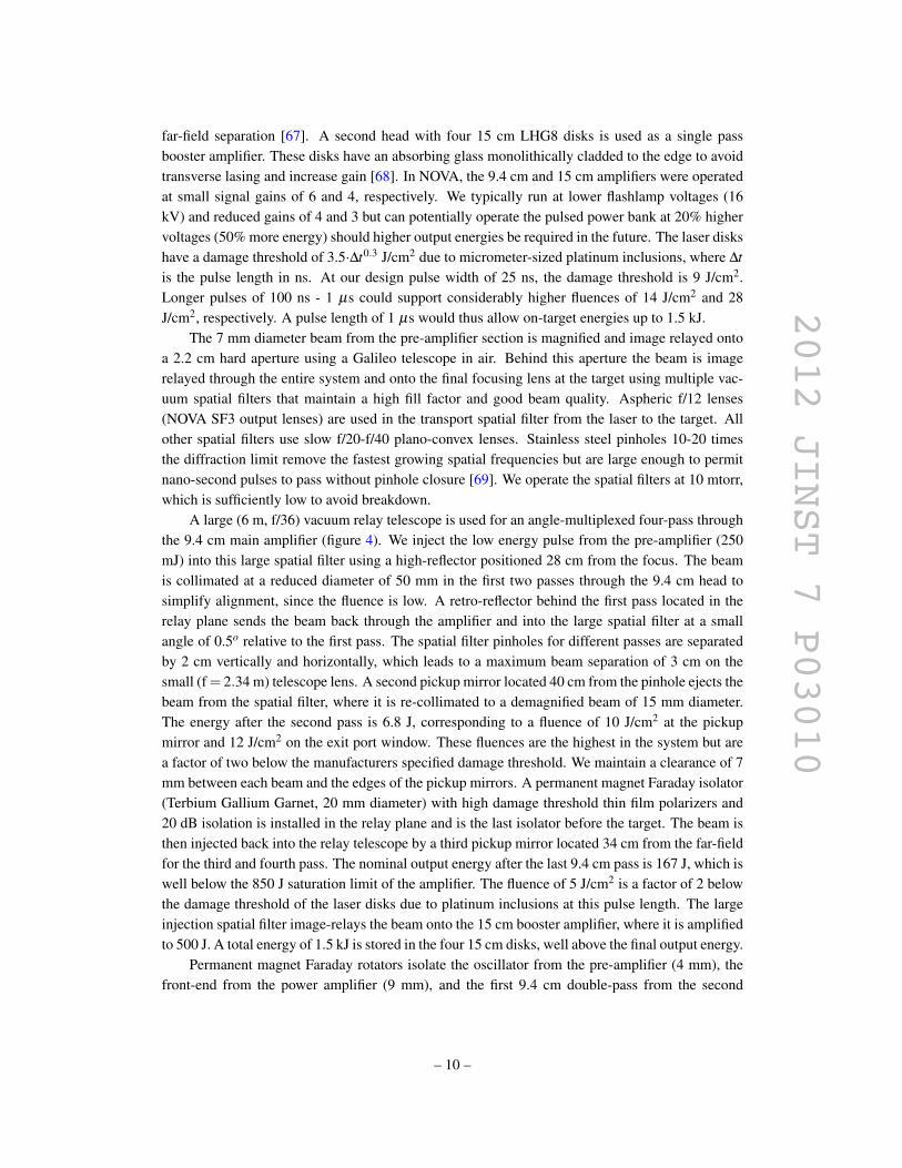
A large (6 m, f/36) vacuum relay telescope is used for an angle-multiplexed four-pass through
the 9.4 cm main amplifier (figure 4). We inject the low energy pulse from the pre-amplifier (250
mJ) into this large spatial filter using a high-reflector positioned 28 cm from the focus. The beam
is collimated at a reduced diameter of 50 mm in the first two passes through the 9.4 cm head to
simplify alignment, since the fluence is low. A retro-reflector behind the first pass located in the
relay plane sends the beam back through the amplifier and into the large spatial filter at a small
angle of 0.5o relative to the first pass. The spatial filter pinholes for different passes are separated
by 2 cm vertically and horizontally, which leads to a maximum beam separation of 3 cm on the
small (f = 2.34 m) telescope lens. A second pickup mirror located 40 cm from the pinhole ejects the
beam from the spatial filter, where it is re-collimated to a demagnified beam of 15 mm diameter.
The energy after the second pass is 6.8 J, corresponding to a fluence of 10 J/cm2 at the pickup
mirror and 12 J/cm2 on the exit port window. These fluences are the highest in the system but are
a factor of two below the manufacturers specified damage threshold. We maintain a clearance of 7
mm between each beam and the edges of the pickup mirrors. A permanent magnet Faraday isolator
(Terbium Gallium Garnet, 20 mm diameter) with high damage threshold thin film polarizers and
20 dB isolation is installed in the relay plane and is the last isolator before the target. The beam is
then injected back into the relay telescope by a third pickup mirror located 34 cm from the far-field
for the third and fourth pass. The nominal output energy after the last 9.4 cm pass is 167 J, which is
well below the 850 J saturation limit of the amplifier. The fluence of 5 J/cm2 is a factor of 2 below
the damage threshold of the laser disks due to platinum inclusions at this pulse length. The large
injection spatial filter image-relays the beam onto the 15 cm booster amplifier, where it is amplified
to 500 J. A total energy of 1.5 kJ is stored in the four 15 cm disks, well above the final output energy.
Permanent magnet Faraday rotators isolate the oscillator from the pre-amplifier (4 mm), the
front-end from the power amplifier (9 mm), and the first 9.4 cm double-pass from the second
– 10 –
2012 JINST 7 P03010
Figure 4. Optical layout of the power-amplifier section, including the injection spatial filter for angular
multiplexing, the two Brewster disk amplifiers, and the transport telescope to the target. The close-up in the
lower-right corner shows the geometry used for far-field separation and the final Faraday rotator.
double-pass (20 mm). There are no large aperture Faraday isolators beyond the third pass. The
final isolator can tolerate a peak reflected energy around 10 J, corresponding to a maximum allow-
able backscatter level from the target of 130 mJ (0.025%) prior to re-amplification in the booster
amplifier and the last 9.4 cm double-pass. We rely on the transport spatial filter between the target
and the booster amplifier to remove accidental back reflections from the target. Baffles around the
pinholes in each spatial filter reduce the acceptance cone of the laser system for back reflections
to less then 0.05o. All optical surfaces beyond the injection spatial filter are slightly tilted (∼ 1o)
to steer low-level back reflections from the anti-reflective coatings outside the spatial filter accep-
tance cone. In experiments the laser beam illuminates the target at an angle of several degrees
relative to the target normal at all times to avoid retro-reflections directly through the pinholes. At
intensities used for a typical shock experiment (1011-1013 W/cm2), backscatter due to stimulated
Brillouin scattering (SBS) from the laser plasma is well below the allowable limit of 130 mJ but
is monitored carefully in each shot (section 3.3). Experiments at higher power will be performed
with a frequency doubled beam (400 J at 527 nm) to move the wavelength of the SBS (∼ 527 nm)
away from the gain-curve of the laser glass. We maintain a p-polarized beam through the system
to simplify mounting of thin film polarizers and Brewster windows.
– 11 –
2012 JINST 7 P03010
The phosphate disks are hygroscopic and had to be resurfaced at 30-10 scratch dig and 1/8
λ since they were not kept in a controlled environment for several years. The cylindrical NOVA
amplifiers were assembled in-house using a vertical assembly station that allows removal of the
flange and blast-shield without damage to the structure that holds the glass (so called bird-cage).
In order to protect the glass from humidity, we purge each amplifier with dry air at 30 standard
cubic feet per hour (SCFH) at all times to maintain a positive pressure in the hermetically sealed
housings. Large aperture Brewster windows are installed at both ends of the amplifier housing for
beam entry. Dry air is produced on site by a compressed air dryer (Parker UDA-300NA), which
delivers 390 SCFH at 200 K dew point at the 60 psig compressed air pressure. The air flow is
temporarily stopped for a laser shot and is increased to 300 SCFH for 15 minutes after the shot to
speed up cooling of the lamps and disks. We measure an increase in temperature of the gas purge
by 1 K per full system shot. Without active cooling the temperature decreases exponentially with
a half-time of 5 hours. Active cooling reduces the half-time to less than one hour. With active
cooling and a 45 minute shot cycle we measure no loss due to thermal wavefront distortions in the
four-pass spatial filter. Faster shot rates cause significant energy loss in the pinholes. Flow rates
through the disk and lamp chambers are adjusted to be identical to avoid stress on the cylindrical
pyrex blast shield that separates the lamp chamber from the disk chamber. We replaced the origi-
nal silver plated reflectors from NOVA that surround the flash-tubes in the amplifier housing (80%
reflectivity) with highly reflective aluminum (Anolux MIRO-SILVER, > 98% reflectivity) which
does not tarnish due to the oxygen in the dry air purge. Instead of the shaped single-cusp reflectors
from the original NOVA design [68], we use a simple cylindrical reflector geometry.
The system incorporates several countermeasures to avoid parasitic oscillations, ghost reflec-
tions, and pencil beams [70]. Baffles around the pinholes in the spatial filters block direct lines of
sight between end mirrors in the four-pass cavity. Faces of the mirrors are not parallel since we use
injection into the multi-pass by far-field separation. We use Brewster windows instead of flat win-
dows to avoid accidental closed-loop oscillation paths. All spatial filter lenses are tilted to remove
parasitic reflections between the injection filter output lens and the 9.4 cm retro-mirror. Tilting the
lenses also steers the beam-cones of ghost reflections in the spatial filters away from the pinholes
and avoids formation of pencil beams. Edges of beam ports into spatial filters and amplifiers have
been sand-blasted to remove accidental specular reflections. All optics have been positioned such
that the foci of converging ghosts do not fall inside optical components, in particular the amplifier
disks. We find no evidence of parasitics or pencil beams with a continuous wave probe laser at
1053 nm when the power amplifier section is fired at full gain (1875).
3.2 Pulsed power
The two disk amplifiers are driven by a 420 kJ capacitor bank with high-current ignitron switches,
configured similarly to the original NOVA design [71]. The 9.4 cm amplifier contains 16 flash-
tubes connected to pulse forming networks (PFN) in 12 pairs of in-series connected lamps. The
15 cm amplifier contains 24 flash-tubes. Each lamp pair is driven by two paralleled 52 µF / 22
kV capacitors in one circuit. The entire bank consists of 20 such circuits with a total capacitance
of 2 mF that stores 40 C at 20 kV. Each PFN includes a 450 µH inductor (Stangeness) connected
in series with the capacitors to stretch the current pulse length to more than 1 ms and limit the
current to 4 kA. The resistivity of the flashlamps (≥ 2 Ω after breakdown) damps the circuit so that
– 12 –

2012 JINST 7 P03010
Figure 5. Schematic of the pulsed power including the PSU protection circuit, dual ignitron switch, and one
circuit with series flashlamp load. The other 19 circuits are connect in parallel to the ignitron HV and ground
distribution plates (not shown).
only a small reverse current appears at the capacitors and the high-current switch. The capacitor
housings are isolated from the support frame by polyvinyl chloride sheets (PVC) and connected to
pulsed power ground via 15 Ω tube resistors. Each frame is electrically isolated from the ground
and connected to pulsed power ground via 100 Ω disc-resistors (22 kV, HVR Advanced Power
Components), which can dissipate 135 kJ in case of accidental arcing. Each circuit includes a high
current fuse (4400 A2s, NOVA 4000 from Pulsed Power Components), 3.9 kΩ charge resistor, and
a shorting switch with 5 Ω dump resistor for overvoltage protection. Each capacitor pair can be
safely discharged in less than a second through a 1 kΩ disc resistor (22 kV, 48 kJ max, 22 kJ/hr,
HVR Advanced Power Components) with a pneumatic dump-switch. Figure 5 shows a schematic
of the pulsed power circuit design, including the protection circuit for the power supply unit (PSU),
high-current ignitron switch, and the PFN for one flashlamp pair.
We employ a separate high current switch for the 9.4 cm bank (8 circuits) and the 15 cm bank
(12 circuits). Thus, each amplifier can be fired independently. Following the original NOVA de-
sign we use a dual-ignitron switch for each bank with two ignitrons (General Electric 37207A) in
series to prevent premature breakdown. A capacitive voltage divider consisting of two 10 MΩ tube
resistors paralleled by 100 nF capacitors (HIVOLT Capacitors Limited, PMR250-104AX, 25 kV)
ensure equal division of the supply voltage across the two ignitrons. The ignitrons are water cooled
to 290 K with a closed loop de-ionized water chiller (300 W, 1 l/m). We monitor and maintain a
conductivity below 20 µS/cm, which corresponds to an additional resistance of 20 MΩ per ignitron
in parallel with the voltage divider caused by the 1.2 m long water hose. Each anode is heated with
a 60 W ceramic emitter (Tempco CRR6) at a distance of 15 cm to prevent condensation of the
mercury. We maintain a minimum temperature difference of 10 K between anode and cathode at
all times to guarantee a hold off voltage of 20 kV. Ignitrons are triggered by a commercial four-
channel trigger generator (3.5 J at 1.9 kV, GBS Elektronik GmbH) using only one of the ignitor
– 13 –

2012 JINST 7 P03010
pins per ignitron. The igniters are galvanically decoupled from the trigger board using high current
transformers (Stangeness).
Pulsed power bank and ignitron switches are installed in a 130 ft2 pulsed power cave, with
the ignitron switches mounted on free-standing support structures (so called NOVA brass giant),
which define pulsed power ground and are electrically insulated from the floor. Power transmission
between the capacitor cave and the amplifiers is facilitated by 15 m long RG-217 coaxial cables
routed on fiber-glass trays. An additional RG217 cable is installed between the laser head inner
reflector of each amplifier and the pulsed power ground at the ignitrons to minimize current though
the building ground in case of explosive flashlamp failure. Pulsed power ground and building
ground are connected through a 100 Ω resistor at only one point near the brass giant.
Both banks for the two amplifiers are charged with the same 8 kJ/s (25 kV) power supply in
45 seconds (General Atomics, CCS8). A freewheeling diode assembly with 100 Ω series resistors
(100 W) protects the PSU from an accidental breakdown. In case of voltage reversal, a high-voltage
diode (8 A at 48 kV, 1.5 kA surge current, CKE) will discharge the entire bank through a high power
100 Ω disc-assembly resistor, which can dissipate close to a MJ of energy. The relatively large
voltage drop across the 3.9 kΩ charging resistor and the 100 Ω resistors in the PSU protection cir-
cuit confuses the PSU controller during the charging process, and the final charging voltage on the
bank is several 100 V below the programmed output voltage of the PSU. This offset is highly repro-
ducible from charge to charge and can be compensated for by charging to a slightly higher voltage.
A small capacitor (150 nF, 25 kV) with 100 MΩ bleeding resistor connected to the PSU output
protects the unit from an accidental open load condition. Three normally open high-voltage relays
(40 kV, Ross Engineering Corporation, E40) isolate the ground and the high-voltage terminals for
both banks when charging is complete, immediately before the discharge trigger. Completely iso-
lating the PSU from the pulsed power bank for the discharge protects the unit from voltage reversal
and ensures controlled separation of the pulsed power and building ground. Once the PSU is dis-
connected, the capacitor banks slowly discharge through the voltage divider and cooling water in
the ignitrons (RC = 3.6 hours). We use a field programmable gate array (FPGA) to automatically
control the charging sequence, including the opening of the relays (see section 3.3), to keep this
time to a minimum (10 ms) and reproducible (± 5 ms) from shot to shot. In the charging sequence
the PSU high-voltage output is disabled upon full charge shortly before the charge relays open.
The peak current through the flash-lamps and the discharge pulse length were measured to be
highly reproducible to better than 1% from shot to shot, since we control the charging and discharge
time with an FPGA. We measure a shot-to-shot reproducibility of the on-target energy better than
10% (figure 6), which is comparable to the accuracy of the pyroelectric detectors, and mostly
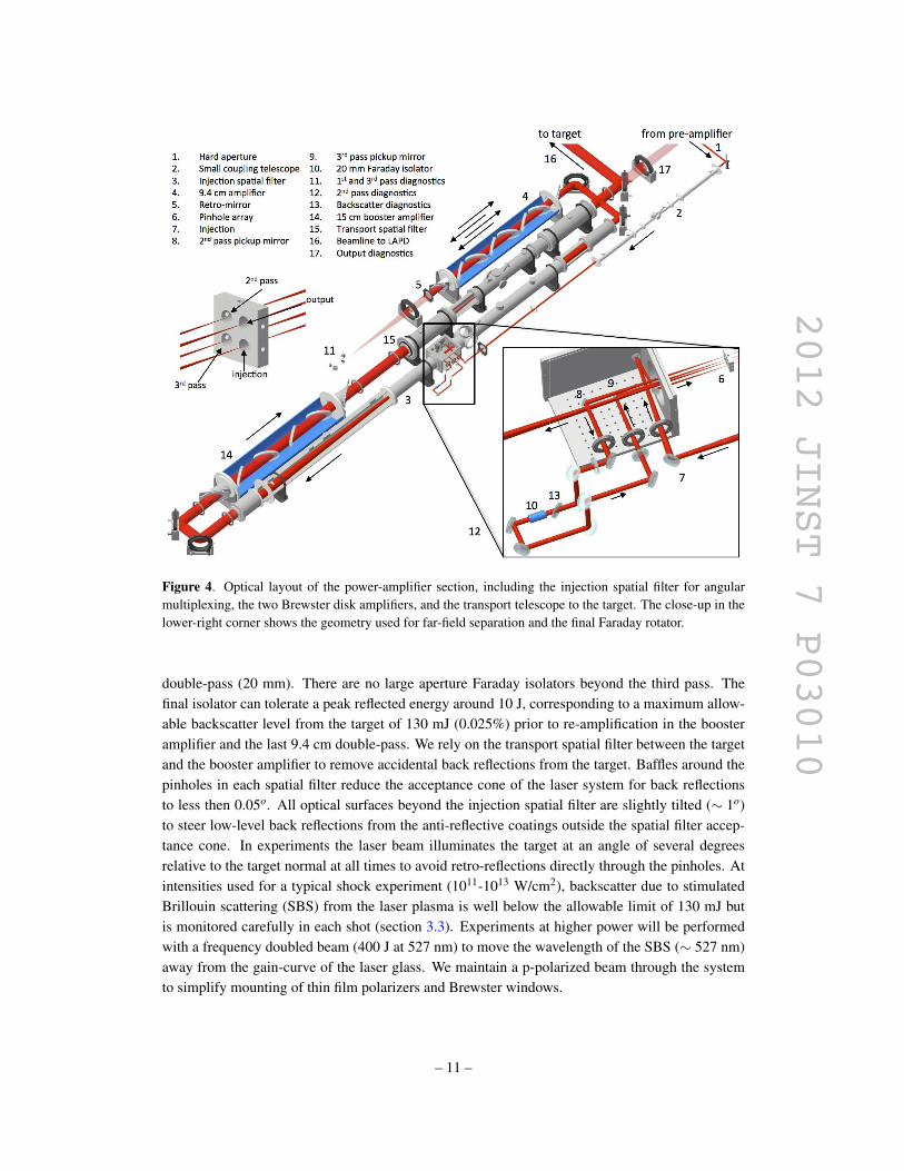
determined by the reproducibility of the flashlamp-pumped oscillator. Figure 6 shows the on-target
energy (relative to the intended energy) as a function of time for a day of laser-shots into the LAPD
with the rod- and disk-amplifiers operating at full gain but the injection energy limited to produce
output energies of 20 J. We maintain a stable output energy with an average shot cycle of 45 minutes
and a minimum time between shots of 30 minutes when the amplifiers are under full thermal load.
We used the original NOVA energy storage capacitors (General Electric type 30F1590), igni-
trons, and charge resistors but replaced the inductors, dump switches and dump resistors, and high
current fuses. We use original NOVA flash-tubes with a length of 44” and xenon fill at 300-700
torr with a light conversion efficiency up to 50%. Although the pulsed power bank and lamps are
– 14 –
2012 JINST 7 P03010
Figure 6. On-target laser-energy (relative to the intended energy) as a function of time for a day of laser-
shots into the LAPD with the Brewster amplifier section operating at full gain but reduced injection energy
(on-target energy limited to 20 J). We maintain a reproducibility better than 10% at an average cooling time
between shots of 45 minutes.
qualified for a nominal bank voltage of 22 kV, the optical system was designed for reduced ampli-
fier gains. We therefore operate the lamps at 16 kV to increase their lifetime without the need of a
low-energy pre-ionization discharge [72].
3.3 Laser control and diagnostics systems
All laser and pulsed power systems are controlled by an array of stand-alone 400 MHz FPGAs (Na-
tional Instruments, CompactRIOTM) connected to each other through a secure 100 Mbps intranet
based on plastic-optical-fiber (POF). Personal computers connected to this intranet only monitor
the FPGA status through network shared variables but do not control any crucial or time sensitive
systems. Areas in the laboratory that are physically separated (pulsed power cave, laser tables, tar-
get area, control room) use individual FPGAs for data acquisition and control. We employ plastic
fiber senders and receivers (IF-D92 & IF-E96 or IF-D96F, Industrial Fiber Optics) for slow triggers
(> 12 ns) from trigger generators centrally located in the control room. Only a few triggers (e.g.
Q-switches) require higher bandwidth and use RG58 coaxial cable in combination with 500 MHz
transformers for ground separation. Besides one dedicated facility ground connection to each area
through a central cable raceway, there is no additional connection through the signal cables to avoid
ground loops. The cable raceway is connect to facility ground at only one point near the PSU.
The control system consists of more than 500 input/output channels, including fast digitizers
for laser-pulse shape, flashlamp current and beam energy measurements, CCD cameras for beam
diagnostics, and stepper motor controllers for spatial filter pinhole and wave plate adjustments. A
separate FPGA is used for a laser-safety interlock that connects to sensors and controls throughout
the laboratory via plastic optical fibers.
Pulsed power diagnostics include a self-powered high-voltage to frequency converter board on
each ignitron switch, coupled to the pulsed-power-FPGA with plastic fiber senders and receivers
to measure the actual voltage on each bank. The discharge current through each lamp pair and the
– 15 –
2012 JINST 7 P03010
reflector return cables are measured with current transformers (Cymatics, 500:1, 3 V/kA) coupled
to 12 bit, 100 kS/s digitizers on the FPGA.
Beam parameters are monitored throughout the system by diagnosing low-power leaks
through the retro-reflector and turning mirrors. Near-field and far-field are recorded on 12-bit
charge-coupled-device (CCD) cameras (AVT Manta or Prosilica GigE cameras). We remove the
protective-glass on the CCDs to avoid fringing due to interference of the nanosecond beam. An
aspheric f/10 lens (original 5” diameter NOVA SF3 input lens) relay-images the retro-mirror plane
onto two cameras for near-field measurements of the first and third pass. The leaks from the two
passes are separated at the far-field, where the beams are offset by 8 mm. Similarly, the second
pass is monitored behind the 20 mm rotator, and the final output behind the transport telescope.
At each location both near-field and far-field are recorded on the same CCD using beam-splitters
to save cost. Beam energy is measured with pyroelectric detectors (Coherent J8LP) coupled to
16 bit, 100 kS/s digitizers on the FPGAs. Single-mode optical fiber (Thorlabs 1060XP FC/FC) is
used to transmit pulse shape information to fast photodetectors (InGaAs, 1.2 GHz) in the control
room 15 m away. Backreflections from the target or misaligned optical surfaces are monitored with
a combination of calorimeters and fiber-coupled photo-diodes at the polarizers of each Faraday
isolator. All pinholes in the spatial filters are installed on three-dimensional motorized stages and
can be easily moved out of the beam for alignment. Low cost stepper motor controllers (Trinamic
TMCM-610) coupled to the FPGA are used with no encoder feedback.
4 Conclusion
In summary, we have commissioned a new kilojoule-class laser at the LAPD to create a unique
instrument for laboratory experiments on collisionless shocks and related phenomena. The
system will deliver 500 J at 1053 nm in 25 ns to a target inside the LAPD-plasma at a shot-rate
of 12-15 shots/day and on-target intensities in excess of 1013 W/cm2. The laser will produce
rapidly-expanding plasma clouds exploding with Alfvenic Mach-numbers up to 7 over more than
10 c/ωpi across the field, and more than 300 c/ωpi along the field. Two-dimensional hybrid
simulations show that collisionless shocks with relevance to space and astrophysical phenomena
can form at these conditions. The large size of the ambient plasma will allow Alfven waves to
participate in the evolution of the shocks. Initial experiments with 20 J on target were performed
at much lower densities than required for a shock to form. These experiments reproduce the basic
features of the simulations and show the formation a diamagnetic cavity that can act as efficient
piston upon the ambient plasma.
Acknowledgments
This work was supported by the Department of Energy (DOE) through the the DOE/NSF Part-
nership in Basic Plasma Science and the American Recovery and Reinvestment Act under con-
tract number DE-FG02-06ER54906. We thank R. Wuerker for additional support through a gen-
erous donation. The experiments were performed at the UCLA Basic Plasma Science Facility
(BaPSF). We thank R. Wuerker1, B. LeGalloudec2, P. Pribyl1, and M. Ringuette3 for help with the
pulsed power, R. Wuerker1, J. Caird4, A. Erlandson4, R. Campbell4, T. Shimada5, R. Johnson5,
– 16 –
2012 JINST 7 P03010
and E. Gaul3 for help with the optical design, J. Bielecki4 and J. Bonlie4 for advise on refurbish-
ing the NOVA amplifiers, R. Richards1, R. Wuerker1, R. Peccei1, G. Fichman1, G. Morales1, F.
Coroniti1, C. Keane4, E. Moses4, S. Samuelson4, R. Ehrlich4, and C. Reaves1 for making the NOVA
laser components available, S. Glenzer4, D. Price4, P. Wiewior1, R. Presura1, A. Covington1, and
D. Montgomery5 for providing additional hardware, H. Lockart1, S. Samaan1, A. Bondarenko1,
M. Weissbart1, M. Drandel1, M. Runkel4, N. Kugland4, and J. Rudnick1 for help with the in-
frastructure, A. Bayramian4 and C. Ebbers4 for help with laser diagnostics, S. Tripathi1, and B.
VanCompernolle1 for help with the experiment, and A. Ng6 for the donation of the Phoenix glass
laser system.
References
[1] D.S. Spicer, R.W. Clark and S.P. Maran, A model of the pre-Sedov expansion phase of supernova
remnant-ambient plasma coupling and X-ray emission from SN 1987A, Astrophys. J. 356 (1990) 549.
[2] L.F. Burlaga et al., Fast ejecta during the ascending phase of solar cycle 23: ACE observations,
1998–1999, J. Geophys. Res. 106 (2001) 20957.
[3] T. Gold and S. Soter, Cometary impact and the magnetization of the moon, Planet. Space Sci. 24
(1976) 45.
[4] P. Dyal, Particle and field measurements of the Starfish diamagnetic cavity, J. Geophys. Res. 111
(2006) A12211.
[5] R.A. Treumann, Fundamentals of collisionless shocks for astrophysical application, 1.
Non-relativistic shocks, Astron. Astrophys. Rev. 17 (2009) 409.
[6] W.P. Wilkinson, The earth’s quasi-parallel bow shock: review of observations and perspectives for
cluster, Planet. Space Sci. 51 (2003) 629.
[7] R.P. Drake, The design of laboratory experiments to produce collisionless shocks of cosmic relevance,
Phys. Plasmas 7 (2000) 4690.
[8] B.A. Remington, R.P. Drake, H. Takabe and D. Arnett, A review of astrophysics experiments on
intense lasers, Phys. Plasmas 7 (2000) 1641.
[9] D.D. Ryutov, B.A. Remington and H.F. Robey, Magnetohydrodynamic scaling: from astrophysics to
the laboratory, Phys. Plasmas 8 (2001) 1804.
[10] Y.P. Zakharov, Collisionless laboratory astrophysics with lasers, IEEE Trans. Plasma Sci. 31 (2003)
1243.
[11] N. Ness, C. Scearce and J. Seek, Initial results of the Imp 1 magnetic field experiment, J. Geophys.
Res. 69 (1964) 3531.
[12] D. Biskamp, Collisionless shock waves in plasmas, Nucl. Fusion 13 (1973) 719.
1Department of Physics and Astronomy, University of California Los Angeles, 1040 Veteran Ave., Los Angeles, CA
90095, U.S.A.2Nevada Terawatt Facility, University of Nevada Reno, 5625 Fox. Ave., Reno, NV 89506, U.S.A.3Department of Physics, University of Texas Austin, 405 W. 25th Street, Austin, TX 78712, U.S.A.4Lawrence Livermore National Laboratory, 7000 East Ave., Livermore, CA 94550, U.S.A.5Los Alamos National Laboratory, Bikini Atoll Rd. , SM 30, Los Alamos, NM 87545, U.S.A.6Department of Physics and Astronomy, University of British Columbia, 2329 West Mall, Vancouver, B.C., Canada.
– 17 –
2012 JINST 7 P03010
[13] A.Y. Cheung, R.R. Goforth and D.W. Koopman, Magnetically induced collisionless coupling between
counterstreaming laser-produced plasmas, Phys. Rev. Lett. 31 (1973) 429.
[14] B. Ripin et al., Sub-Alfvenic plasma expansion, Phys. Fluids B 5 (1993) 3491.
[15] B. Ripin et al., Large-Larmor-radius interchange instability, Phys. Rev. Lett. 59 (1987) 2299.
[16] W. Gekelman et al., Design, construction, and properties of the large plasma research device — the
LAPD at UCLA, Rev. Sci. Instrum. 62 (1991) 2875.
[17] W. Gekelman et al., The many faces of shear Alfven waves, Phys. Plasmas 18 (2011) 055501.
[18] D.R. Farley et al., Radiative jet experiments of astrophysical interest using intense lasers, Phys. Rev.
Lett. 83 (1999) 1982.
[19] J. Grun et al., Laser-plasma simulations of astrophysical phenomena and novel applications to
semiconductor annealing, Laser Part. Beams 21 (2003) 529.
[20] M. Yamada, R. Kulsrud and H. Ji, Magnetic reconnection, Rev. Mod. Phys. 82 (2010) 603.
[21] T.A. Carter, B. Brugman, P. Pribyl and W. Lybarger, Laboratory observation of a nonlinear
interaction between shear Alfven waves, Phys. Rev. Lett. 96 (2006) 155001.
[22] W. Gekelman, A. Collette and S. Vincena, Three-dimensional current systems generated by plasmas
colliding in a background magnetoplasma, Phys. Plasmas 14 (2007) 062109.
[23] D.B. Schaeffer et al., A scalable multipass laser cavity based on injection by frequency conversion for
noncollective Thomson scattering, Rev. Sci. Instrum. 81 (2010) 10D518.
[24] S.J. Zweben, J. Caird, W. Davis, D.W. Johnson and B.P. Le Blanc, Plasma turbulence imaging using
high-power laser Thomson scattering, Rev. Sci. Instrum. 72 (2001) 1151.
[25] G. Gregori et al., Effect of nonlocal transport on heat-wave propagation, Phys. Rev. Lett. 92 (2004)
205006.
[26] J.L. Kline, D.S. Montgomery, R.P. Johnson and T. Shimada, Measuring electron heat conduction in
non-uniform laser-produced plasmas using imaging Thomson scattering, 2010 JINST 5 P11005.
[27] K.B. Fournier et al., Efficient multi-keV X-ray sources from Ti-doped aerogel targets, Phys. Rev. Lett.
92 (2004) 165005.
[28] O.L. Landen et al., Dense matter characterization by X-ray Thomson scattering, J. Quant. Spectrosc.
Radiat. Trans. 71 (2001) 465.
[29] S.H. Glenzer and R. Redmer, X-ray Thomson scattering in high energy density plasmas, Rev. Mod.
Phys. 81 (2009) 1625.
[30] S. LePape et al., X-ray radiography and scattering diagnosis of dense shock-compressed matter,
Phys. Plasmas 17 (2010) 056309.
[31] M.M. Leroy, Structure of perpendicular shocks in collisionless plasma, Phys. Fluids 26 (1983) 2742.
[32] C.S. Wu, Physical mechanisms for turbulent dissipation in collisionless shock waves, Space Sci. Rev.
32 (1982) 83.
[33] C.S. Wu et al., Microinstabilities associated with a high Mach number, perpendicular bow shock,
Space Sci. Rev. 37 (1984) 63.
[34] J.R. Kan, M.E. Mandt and L.H. Lyu, Quasi-parallel collisionless shocks, Space Sci. Rev. 57 (1991)
201.
– 18 –
2012 JINST 7 P03010
[35] N. Omidi, X. Blanco-Cano, C.T. Russell, H. Karimabadi and M. Acuna, Hybrid simulations of solar
wind interaction with magnetized asteroids: general characteristics, J. Geophys. Res. 107 (2002)
1487.
[36] D.A. Tidman and N.A. Krall, Shock waves in collisionless plasmas, S.C. Brown ed., Wiley, New York
U.S.A. (1971).
[37] B.T. Draine, Theory of interstellar shocks, Ann. Rev. Astron. Astrophys. 31 (1993) 373.
[38] L. Spitzer Jr., Physics of fully ionized gases, 2nd ed., Wiley, New York U.S.A. (1962).
[39] H.W. Friedman, L.M. Linson, R.M. Patrick and H.E. Petschek, Collisionless shocks in plasmas, Ann.
Rev. Fluid Mech. 3 (1971) 63.
[40] R.M. Patrick and E.R. Pugh, Plasma wind tunnel studies of collision-free flows and shocks, Phys.
Fluids 10 (1967) 2579.
[41] D. Koopman, Momentum transfer interaction of a laser-produced plasma with a low-pressure
background, Phys. Fluids 15 (1972) 1959.
[42] C. Niemann et al., Collisionless shocks in a large magnetized laser-plasma plume, IEEE Trans.
Plasma Sci. 39 (2011) 2406.
[43] D. Schaeffer et al., Thomson scattering measurements of temperature and density in a low-density,
laser-driven magnetized plasma, 2012 JINST 7 P02002.
[44] Y. Kuramitsu et al., Time evolution of collisionless shock in counterstreaming laser-produced
plasmas, Phys. Rev. Lett. 106 (2011) 175002.
[45] M. VanZeeland, W. Gekelman, S. Vincena and G. Dimonte, Production of Alfven waves by a rapidly
expanding dense plasma, Phys. Rev. Lett. 87 (2001) 105001.
[46] W. Gekelman, M. Van Zeeland, S. Vincena and P. Pribyl, Laboratory experiments on Alfven waves
caused by rapidly expanding plasmas and their relationship to space phenomena, J. Geophys. Res.
108 (2003) 1281.
[47] S. Vincena, W. Gekelman, M.A. Van Zeeland, J. Maggs and A. Collette, Quasielectrostatic whistler
wave radiation from the hot electron emission of a laser-produced plasma, Phys. Plasmas 15 (2008)
072114.
[48] A. Collette and W. Gekelman, Structure of an exploding laser-produced plasma, Phys. Rev. Lett. 105
(2010) 195003.
[49] J.F. Hansen et al., A new method to generate dust with astrophysical properties, 2011 JINST 6
P05010.
[50] B. Meyer and G. Thiell, Experimental scaling laws for ablation parameters in plane target-laser
interaction with 1.06 µm and 0.35 µm laser wavelengths, Phys. Fluids 27 (1984) 302.
[51] C. Cooper, W. Gekelman, P. Pribyl and Z. Lucky, A new large area lanthanum hexaboride plasma
source, Rev. Sci. Instrum. 81 (2010) 083503.
[52] S. Kacenjar et al., Magnetic field compression and evolution in laser-produced plasma expansions,
Phys. Fluids 29 (1986) 2007.
[53] C. Constantin et al., Collisionless interaction of an energetic laser produced plasma with a large
magnetoplasma, Astrophys. Space Sci. 322 (2009) 155.
[54] A. Zylstra et al., Ion velocity distribution measurements in a magnetized laser plasma expansion,
2010 JINST 5 P06004.
– 19 –
2012 JINST 7 P03010
[55] E.T. Everson et al., Design, construction, and calibration of a three-axis, high-frequency magnetic
probe (B-dot probe) as a diagnostic for exploding plasmas, Rev. Sci. Instrum. 80 (2009) 113505.
[56] D. Winske and S.P. Gary, Hybrid simulations of debris-ambient ion interactions in astrophysical
explosions, J. Geophys. Res. 112 (2007) A10303.
[57] C.B. Dane, L.E. Zapata, W.A. Neuman, M.A. Norton and L.A. Hackel Design and operation of a
150 W near diffraction-limited laser amplifier with SBS wavefront correction, IEEE J. Quant.
Electron. 31 (1995) 148.
[58] J.D. Bonlie, F. Patterson, D. Price, B. White and P. Springer, Production of > 1021 W/cm2 from a
large-aperture. Ti:sapphire laser system, Appl. Phys. B 70 (2000) S155.
[59] M. Roth et al., PHELIX: a Petawatt High-Energy Laser for heavy Ion Experiments, Proc. SPIE 4424
(2001) 78.
[60] M. Nostrand et al., A large-aperture high-energy laser system for optics and optical component
testing, Proc. SPIE 5273 (2004) 325.
[61] M. Martinez et al., The Texas petawatt laser, Proc. SPIE 5991 (2005) 59911N.
[62] P.P. Wiewior, V.V. Ivanov and O. Chalyy, Development of the 50 TW laser for joint experiments with
1 MA z-pinches, J. Phys. Conf. Ser. 244 (2010) 032013.
[63] E.M. Campbell, J.T. Hunt, E.S. Bliss, D.R. Speck and R.P. Drake, Nova experimental facility
(invited), Rev. Sci. Instrum. 57 (1986) 2101.
[64] E. Moses and C.R. Wuest, The national ignition facility: laser performance and first experiments,
Fusion Sci. Technol. 47 (2005) 314.
[65] C. Bibeau et al., Power, energy, and temporal performance of the Nova laser facility with recent
improvements to the amplifier system, Appl. Opt. 31 (1992) 5799.
[66] G.F. Albrecht, B. Comaskey and L. Furu, A 1.4 kJ solid-state power oscillator with good beam
quality, IEEE J. Quant. Electron. 31 (1995) 164.
[67] B.M. Van Wonterghem et al., Performance of a prototype for a large-aperture multipass Nd:glass
laser for inertial confinement fusion, Appl. Opt. 36 (1997) 4932.
[68] W.E. Martin, J.B. Trenholme, G.J. Linford, S.M. Yarema and C.A. Hurley, Solid-state disk amplifiers
for fusion-laser systems, IEEE J. Quant. Electron. 17 (1981) 1744.
[69] J.M. Auerbach, N.C. Holmes, J.T. Hunt and G.J. Lindford, Closure phenomena in pinholes irradiated
by Nd laser pulses, Appl. Opt. 18 (1979) 2495.
[70] M.J. Norman et al., Multipass reconfiguration of the HELEN Nd:glass laser at the atomic weapons
establishment, Appl. Opt. 41 (2002) 3497.
[71] K. Whitham, B. Merritt, R. Holloway, D. Gritton and J. Oicles, Nova power. System and energy
storage, in Proceedings of the 9th Symposium on Engineering Problems of Fusion Research, Chicago
U.S.A. October 1981.
[72] S. Semek, B. LeGalloudec and W. McDaniel, A new approach to the preionization of flash lamps in
power lasers, Rev. Sci. Instrum. 78 (2007) 126104.
– 20 –