high-density 802.11ac wi-fi design and deployment for large public venues
TRANSCRIPT

#ATM15 |
Very High Density 802.11ac Networks
Chuck Lukaszewski, CWNE #112
@ArubaNetworks

CONFIDENTIAL © Copyright 2015. Aruba Networks, Inc. All rights reserved2#ATM15 |
Agenda
• Announcing New Very High Density VRD
• 802.11ac vs. 802.11n @VHD
• 80-MHz vs. 40-MHz vs. 20-MHz Channels
• DFS Channels
• New VHD Capacity Planning Methodology
• How 802.11 Channels Behave Under High Load
• Understanding 802.11 TXOP Airtime Usage
• Collision Domains & RF Spatial Reuse

CONFIDENTIAL © Copyright 2015. Aruba Networks, Inc. All rights reserved3#ATM15 |
Announcing New Very High Density VRD
• 100% 802.11ac
• End-to-end system architecture & dimensioning
• New capacity planning methodology
• Addresses a wide range of customer use cases
• Available late March
CONFIDENTIAL © Copyright 2015. Aruba Networks, Inc. All rights reserved4#ATM15 |
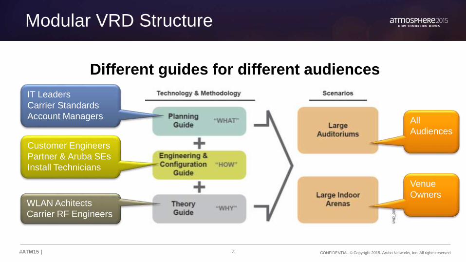
Modular VRD Structure
Different guides for different audiences
IT Leaders
Carrier Standards
Account Managers
Customer Engineers
Partner & Aruba SEs
Install Technicians
WLAN Achitects
Carrier RF Engineers
All
Audiences
Venue
Owners

5#ATM15 |
802.11ac vs. 802.11n @VHD

6 CONFIDENTIAL © Copyright 2015. Aruba Networks, Inc. All rights reserved#ATM15 |
How Far We’ve Come
• “Coverage” WLANs came first
• These evolved into “Capacity” WLANs (with limited HD zones)
– 250m2 / 2500 ft2 = 25 devices per cell
• BYOD made every capacity WLAN a high-density network
– 3 devices/person = 75 per cell
• HD WLANs from 2011 are now very high-density (VHD)
– 100+ devices per “cell”. Devices may be associated to multiple BSS operators in same RF domain.
Waiting for the new Pope in St. Peter’s Square
NBC Today Show, February, 2013, http://instagram.com/p/W2BuMLQLRB/

7 CONFIDENTIAL © Copyright 2015. Aruba Networks, Inc. All rights reserved#ATM15 |
How Do 802.11ac Features Impact VHD Design?
802.11ac Technology Promise VHD Impact
80-MHz & 160-MHz
Channels
Increase burst rates for
individual STAs
None. Stay with 20-MHz
channels for VHD areas
256-QAM New MCS rates up to 33%
faster
Minimal. Rates only usable
within ~5m of AP
8 Spatial Streams Peak data rates up to
6.9Gbps
None. In future, clients will be
mostly capped at 2SS
DL MU-MIMO Transmit to 4 STAs at the
“same” time
TBD until Wave2 in 2016.
Sounding overhead offsets gains
Frame Aggregation
(A-MSDU & A-MPDU)
Enable the MAC to keep up
with the 802.11ac PHY
Minimal. Majority of frames in
VHD areas are bursty & small
802.11ac Technology Promise VHD Impact
80-MHz & 160-MHz
Channels
Increase burst rates for
individual STAs
None. Stay with 20-MHz
channels for VHD areas
256-QAM New MCS rates up to 33%
faster
Minimal. Rates only usable
within ~5m of AP
8 Spatial Streams Peak data rates up to
6.9Gbps
None. In future, clients will be
mostly capped at 2SS
DL MU-MIMO Transmit to 4 STAs at the
“same” time
TBD until Wave2 in 2016.
Sounding overhead offsets gains
802.11ac Technology Promise VHD Impact
80-MHz & 160-MHz
Channels
Increase burst rates for
individual STAs
None. Stay with 20-MHz
channels for VHD areas
256-QAM New MCS rates up to 33%
faster
Minimal. Rates only usable
within ~5m of AP
8 Spatial Streams Peak data rates up to
6.9Gbps
None. In future, clients will be
mostly capped at 2SS
802.11ac Technology Promise VHD Impact
80-MHz & 160-MHz
Channels
Increase burst rates for
individual STAs
None. Stay with 20-MHz
channels for VHD areas
256-QAM New MCS rates up to 33%
faster
Minimal. Rates only usable
within ~5m of AP
802.11ac Technology Promise VHD Impact
80-MHz & 160-MHz
Channels
Increase burst rates for
individual STAs
None. Stay with 20-MHz
channels for VHD areas

8 CONFIDENTIAL © Copyright 2015. Aruba Networks, Inc. All rights reserved#ATM15 |
Why 802.11ac Does Matter for VHD
802.11ac Impact Promise VHD Impact
Broad-based DFS
channel support
Open up 15 channels (FCC
domains)
Add up to 750Mbps of capacity
Faster AP CPUs Process small frames and
collisions faster
Increase channel bandwidth
closer to theoretical max
More AP memory Larger table sizes Better handle very high BSSID
count environments
Clients converge to 2SS Increase per-STA burst rate
even in narrow channels
Get clients off the air faster
TxBF Improve SINRs both
directions
Robustness improvement;
client-side CSI feedback
802.11ac Impact Promise VHD Impact
Broad-based DFS
channel support
Open up 15 channels (FCC
domains)
Add up to 750Mbps of capacity
Faster AP CPUs Process small frames and
collisions faster
Increase channel bandwidth
closer to theoretical max
More AP memory Larger table sizes Better handle very high BSSID
count environments
Clients converge to 2SS Increase per-STA burst rate
even in narrow channels
Get clients off the air faster
802.11ac Impact Promise VHD Impact
Broad-based DFS
channel support
Open up 15 channels (FCC
domains)
Add up to 750Mbps of capacity
Faster AP CPUs Process small frames and
collisions faster
Increase channel bandwidth
closer to theoretical max
More AP memory Larger table sizes Better handle very high BSSID
count environments
802.11ac Impact Promise VHD Impact
Broad-based DFS
channel support
Open up 15 channels (FCC
domains)
Add up to 750Mbps of capacity
Faster AP CPUs Process small frames and
collisions faster
Increase channel bandwidth
closer to theoretical max
802.11ac Impact Promise VHD Impact
Broad-based DFS
channel support
Open up 16 channels (FCC
domains)
Add up to 800 Mbps of capacity
@ 50Mbps/channel

9#ATM15 |
80-MHz vs. 40-MHz vs. 20-MHz Channel Widths

10 CONFIDENTIAL © Copyright 2015. Aruba Networks, Inc. All rights reserved#ATM15 |
Why 20-MHz Channels – Reuse Distance
• More channels = more distance between same-channel APs
11 CONFIDENTIAL © Copyright 2015. Aruba Networks, Inc. All rights reserved#ATM15 |
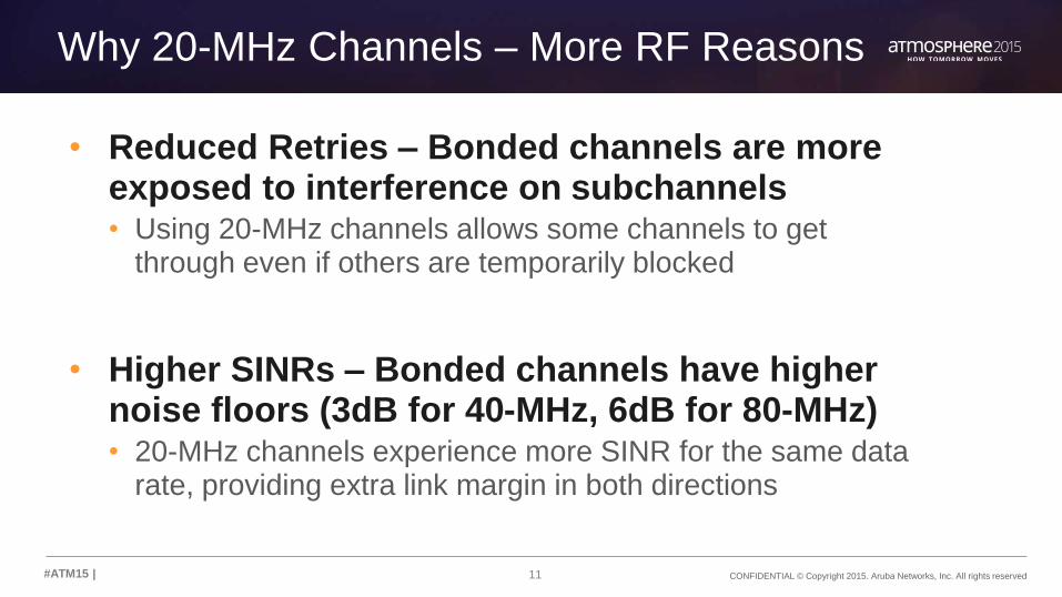
Why 20-MHz Channels – More RF Reasons
• Reduced Retries – Bonded channels are more exposed to interference on subchannels• Using 20-MHz channels allows some channels to get
through even if others are temporarily blocked
• Higher SINRs – Bonded channels have higher noise floors (3dB for 40-MHz, 6dB for 80-MHz)• 20-MHz channels experience more SINR for the same data
rate, providing extra link margin in both directions

12 CONFIDENTIAL © Copyright 2015. Aruba Networks, Inc. All rights reserved#ATM15 |
Why 20-MHz Channels - Performance
Which Chariot test will deliver higher goodput?Each test uses the
exact same 80-MHz
bandwidth
Each test uses the
exact same number
of STAs
Both VHT40 BSS will
victimize each other
with ACI
All four VHT20 BSS
will victimize each
other

13 CONFIDENTIAL © Copyright 2015. Aruba Networks, Inc. All rights reserved#ATM15 |
VHT20 Beats VHT40 & VHT80 – 1SS Clients
0 Mbps
50 Mbps
100 Mbps
150 Mbps
200 Mbps
250 Mbps
300 Mbps
5 10 25 50 75 100
Clients
VHT20x4 Up
VHT20x4 Bidirect
VHT40x2 Up
VHT40x2 Bidirect
VHT80x1 Up
VHT80x1 Bidirect
Down
Up
Bidirect
VHT80 falls off
at 25 STAs
VHT40 falls off
at 75 STAs
14 CONFIDENTIAL © Copyright 2015. Aruba Networks, Inc. All rights reserved#ATM15 |
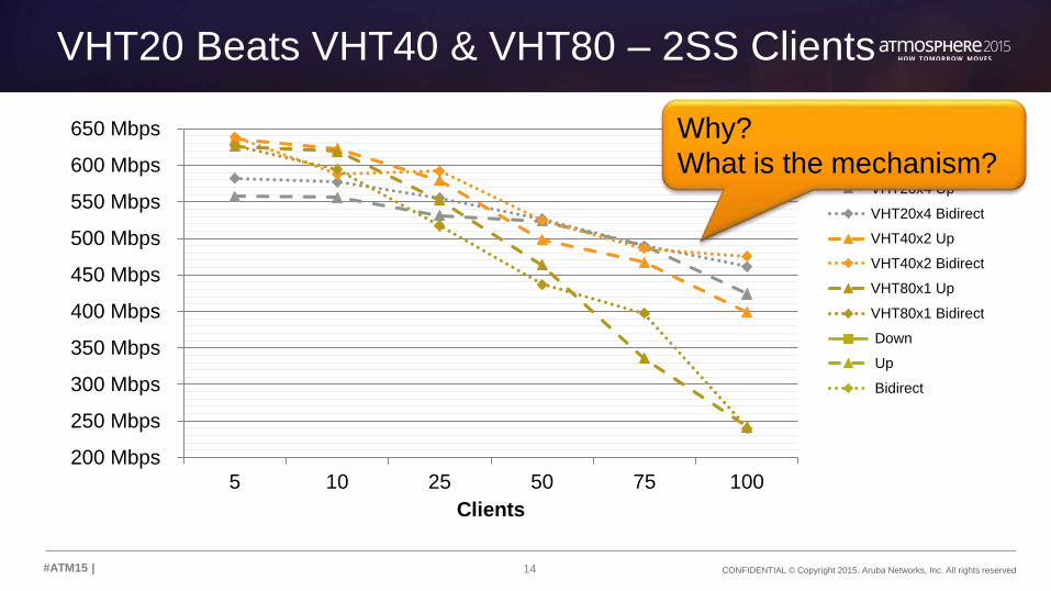
VHT20 Beats VHT40 & VHT80 – 2SS Clients
200 Mbps
250 Mbps
300 Mbps
350 Mbps
400 Mbps
450 Mbps
500 Mbps
550 Mbps
600 Mbps
650 Mbps
5 10 25 50 75 100
Clients
VHT20x4 Up
VHT20x4 Bidirect
VHT40x2 Up
VHT40x2 Bidirect
VHT80x1 Up
VHT80x1 Bidirect
Down
Up
Bidirect
Why?
What is the mechanism?

15#ATM15 |
DFS Channels:
To Use or Not To Use

16 CONFIDENTIAL © Copyright 2015. Aruba Networks, Inc. All rights reserved#ATM15 |
General Rule
Use DFS channels in the USA for VHD areas!!
• The number of collision domains is the primary constraint on VHD capacity
• The number of STAs per collision domain is the second major constraint on capacity
• VHD networks are ultimately about tradeoffs
The benefit of employing DFS channels almost
always* outweighs the cost.

17 CONFIDENTIAL © Copyright 2015. Aruba Networks, Inc. All rights reserved#ATM15 |
DFS Usage Exceptions
1. Client capabilities– If more than 15-20% of the expected clients are proven to be 5-
GHz capable but unable to use DFS
2. Proven, recurring radar events– A DFS survey with the actual APs to be deployed shows regular
events on specific channels.
• Just because certain channels are impacted do not rule out the band
– Survey should be done at multiple locations & elevations
3. Avoid channel 144 until >50% of STAs can see it

18 CONFIDENTIAL © Copyright 2015. Aruba Networks, Inc. All rights reserved#ATM15 |
Balancing the Risks & Rewards
• Client capabilities• As of 2015, the vast majority of mobile devices shipping in USA
support DFS channels
• Non-DFS clients will be able to connect due to stacking of multiple channels (although perhaps at lower rates)
• It is easily worth it to provide a reduced connect speed to a an unpredictable minority of clients, in exchange for higher connect speeds for everyone else all the time
• Radar events• It is worth having a small number of clients occasionally interrupted
in exchange for more capacity for everyone all the time

19#ATM15 |
New Capacity Planning Methodology

20 CONFIDENTIAL © Copyright 2015. Aruba Networks, Inc. All rights reserved#ATM15 |
System vs. Channel vs. Device Throughput
Channel 1
Throughput
Channel 2
Throughput
Channel X
Throughput
Per-Device
Throughput
2.4 GHz 5 GHzTotal
System
Throughput
+
+
+
+
21 CONFIDENTIAL © Copyright 2015. Aruba Networks, Inc. All rights reserved#ATM15 |
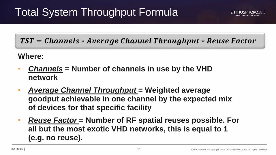
Total System Throughput Formula
Where:
• Channels = Number of channels in use by the VHD network
• Average Channel Throughput = Weighted average goodput achievable in one channel by the expected mix of devices for that specific facility
• Reuse Factor = Number of RF spatial reuses possible. For all but the most exotic VHD networks, this is equal to 1 (e.g. no reuse).
𝑻𝑺𝑻 = 𝑪𝒉𝒂𝒏𝒏𝒆𝒍𝒔 ∗ 𝑨𝒗𝒆𝒓𝒂𝒈𝒆 𝑪𝒉𝒂𝒏𝒏𝒆𝒍 𝑻𝒉𝒓𝒐𝒖𝒈𝒉𝒑𝒖𝒕 ∗ 𝑹𝒆𝒖𝒔𝒆 𝑭𝒂𝒄𝒕𝒐𝒓

22 CONFIDENTIAL © Copyright 2015. Aruba Networks, Inc. All rights reserved#ATM15 |
Step 1 – Choose Channel Count
• US allows:• 9 non-DFS channels
• 13-16 DFS channels*
• Deduct:• Channel 144
• House channel(s)
• Proven radar channels
• AP-specific channel limitations
23 CONFIDENTIAL © Copyright 2015. Aruba Networks, Inc. All rights reserved#ATM15 |
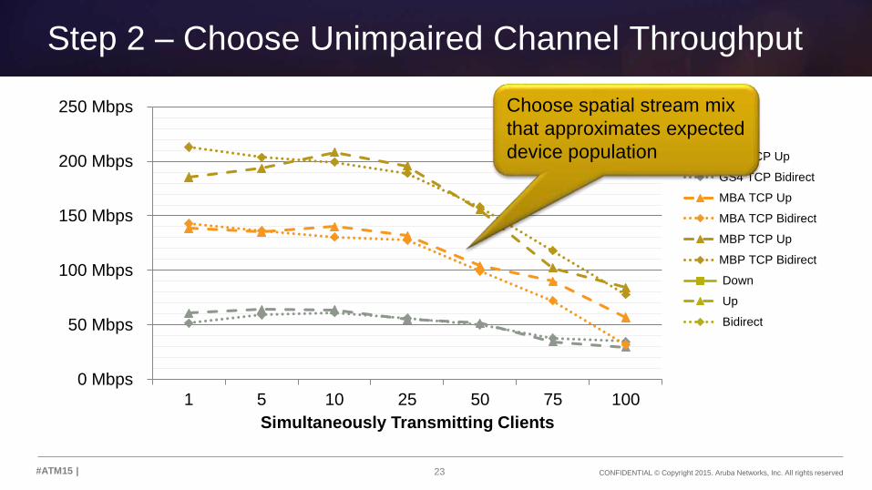
Step 2 – Choose Unimpaired Channel Throughput
0 Mbps
50 Mbps
100 Mbps
150 Mbps
200 Mbps
250 Mbps
1 5 10 25 50 75 100
Simultaneously Transmitting Clients
GS4 TCP Up
GS4 TCP Bidirect
MBA TCP Up
MBA TCP Bidirect
MBP TCP Up
MBP TCP Bidirect
Down
Up
Bidirect
Choose spatial stream mix
that approximates expected
device population
24 CONFIDENTIAL © Copyright 2015. Aruba Networks, Inc. All rights reserved#ATM15 |
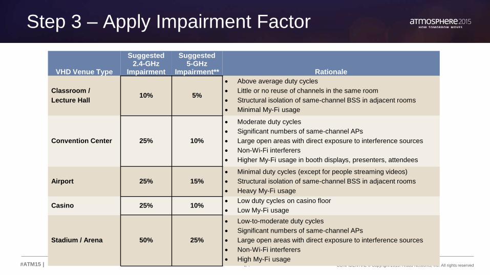
Step 3 – Apply Impairment Factor
VHD Venue Type
Suggested 2.4-GHz
Impairment
Suggested 5-GHz
Impairment** Rationale
Classroom /
Lecture Hall 10% 5%
Above average duty cycles
Little or no reuse of channels in the same room
Structural isolation of same-channel BSS in adjacent rooms
Minimal My-Fi usage
Convention Center 25% 10%
Moderate duty cycles
Significant numbers of same-channel APs
Large open areas with direct exposure to interference sources
Non-Wi-Fi interferers
Higher My-Fi usage in booth displays, presenters, attendees
Airport 25% 15%
Minimal duty cycles (except for people streaming videos)
Structural isolation of same-channel BSS in adjacent rooms
Heavy My-Fi usage
Casino 25% 10% Low duty cycles on casino floor
Low My-Fi usage
Stadium / Arena 50% 25%
Low-to-moderate duty cycles
Significant numbers of same-channel APs
Large open areas with direct exposure to interference sources
Non-Wi-Fi interferers
High My-Fi usage
25 CONFIDENTIAL © Copyright 2015. Aruba Networks, Inc. All rights reserved#ATM15 |
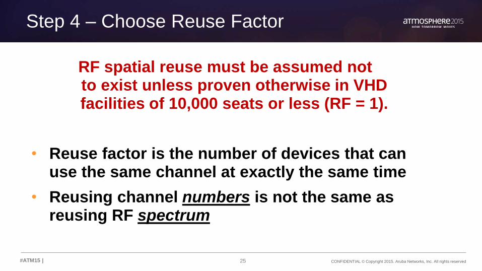
Step 4 – Choose Reuse Factor
RF spatial reuse must be assumed not to exist unless proven otherwise in VHD facilities of 10,000 seats or less (RF = 1).
• Reuse factor is the number of devices that can use the same channel at exactly the same time
• Reusing channel numbers is not the same as reusing RF spectrum

26 CONFIDENTIAL © Copyright 2015. Aruba Networks, Inc. All rights reserved#ATM15 |
Step 5 – Calculate TST By Band
VHD Venue TypeSuggested
5-GHz **Suggested
2.4-GHz
Lecture Hall 5% 10%
Convention Center 10% 25%
Airport 15% 25%
Casino 10% 25%
Stadium / Arena 25% 50%
SpatialStream Mix
50Concurrent
75 Concurrent
100 Concurrent
1SS Device 50 Mbps 38 Mbps 31 Mbps
2SS Device 100 Mbps 72 Mbps 51 Mbps
3SS Device 158 Mbps 118 Mbps 78 Mbps
ChannelType
USA 5-GHzCount
Non-DFS 9
DFS 11
Total 20
Step 1 - Channels Step 2 – Unimpaired Throughput Step 3 – Impairment
# Description ChannelsUnimpaired Throughput
Impaired 5-GHz TP
Impaired2.4-GHz TP Reuse 5-GHz TST 2.4-GHz TST
1Non-DFS Lecture
Hall9 + 3 100Mbps 95Mbps 90Mbps 1 9 * 95Mbps = 855 Mbps 3 * 90Mbps = 270 Mbps
2 DFS Arena 20 + 3 40 Mbps 30 Mbps 20 Mbps 1 20 * 40Mbps = 800 Mbps 3 * 20 Mbps = 60 Mbps
3 DFS Stadium 20 + 3 40 Mbps 30 Mbps 20 Mbps 4 3.2 Gbps 240 Mbps
Step 5 – Calculate TST By Band
# Description ChannelsUnimpaired Throughput
Impaired 5-GHz TP
Impaired2.4-GHz TP Reuse 5-GHz TST 2.4-GHz TST
1Non-DFS Lecture
Hall9 + 3 100Mbps 95Mbps 90Mbps 1 9 * 95Mbps = 855 Mbps 3 * 90Mbps = 270 Mbps
2 DFS Arena 20 + 3 40 Mbps 30 Mbps 20 Mbps 1 20 * 40Mbps = 800 Mbps 3 * 20 Mbps = 60 Mbps
# Description ChannelsUnimpaired Throughput
Impaired 5-GHz TP
Impaired2.4-GHz TP Reuse 5-GHz TST 2.4-GHz TST
1Non-DFS Lecture
Hall9 + 3 100Mbps 95Mbps 90Mbps 1 9 * 95Mbps = 855 Mbps 3 * 90Mbps = 270 Mbps

27 CONFIDENTIAL © Copyright 2015. Aruba Networks, Inc. All rights reserved#ATM15 |
Per-Device Throughput Formula
Where:
• Associated Device Capacity (ADC) = Percentage of seating capacity with an active Wi-Fi device * average number of Wi-Fi devices per person. Typically computed per band.
• Device Duty Cycle = Average percent of time that any given user device attempts to transmit
𝑨𝑷𝑫𝑻 =𝑻𝒐𝒕𝒂𝒍 𝑺𝒚𝒔𝒕𝒆𝒎 𝑻𝒉𝒓𝒐𝒖𝒈𝒉𝒑𝒖𝒕
𝑨𝒔𝒔𝒐𝒄𝒊𝒂𝒕𝒆𝒅 𝑫𝒆𝒗𝒊𝒄𝒆 𝑪𝒂𝒑𝒂𝒄𝒊𝒕𝒚 ∗ 𝑫𝒆𝒗𝒊𝒄𝒆 𝑫𝒖𝒕𝒚 𝑪𝒚𝒄𝒍𝒆
It is generally impossible to guarantee a
specific per-device value in a VHD system.

28 CONFIDENTIAL © Copyright 2015. Aruba Networks, Inc. All rights reserved#ATM15 |
Step 1 – Estimate ADC
• Start with the seating / standing capacity of the VHD area to be covered
• Then estimate the take rate (50% is a common minimum)
• Choose the number of devices expected per person. This varies by venue type. It might be lower in a stadium and higher in a university lecture hall or convention center salon.
– For example, 50% of a 70,000 seat stadium would be 35,000 devices assuming each user has a single device
– 100% of a 1,000 seat lecture hall where every student has an average of 2.5 devices would have an ADC equal to 2,500
• More users should be on 5-GHz than 2.4-GHz. ADC should be computed by frequency band. In general you should target a ratio of 75% / 25%.
• Association demand is assumed to be evenly distributed throughout the coverage space.

29 CONFIDENTIAL © Copyright 2015. Aruba Networks, Inc. All rights reserved#ATM15 |
Step 2 – Choose a Device Duty Cycle
• Subjective decision made by the network architect, based on expected user applications
• This duty cycle is %Time the user or device wants to perform this activity. • It is not the same as the application duty cycle!
Category Duty Cycle User & Device Behavior Examples
Background 5% Network keepalive / App phonehome
Checking In 10% Web browsing / Checking email / Social updates
Semi-Focused 25% Streaming scores / Online exam
Working 50% Virtual desktop
Active 100% Video streaming / Voice streaming / Gaming

30 CONFIDENTIAL © Copyright 2015. Aruba Networks, Inc. All rights reserved#ATM15 |
Examples
# Description SeatsTake Rate
Devices/ Person ADC
3 DFS Stadium 60K 50% 1 30K
# Description SeatsTake Rate
Devices/ Person ADC
1 Lecture Hall 500 75% 2.5 938
# Description SeatsTake Rate
Devices/ Person ADC
2 DFS Arena 20K 50% 1 10K
5-GHz Per-DeviceGoodput
2.4-GHz Per-DeviceGoodput
𝟖𝟓𝟓 𝑴𝒃𝒑𝒔
𝟒𝟔𝟗 ∗ 𝟐𝟎%= 𝟗𝑴𝒃𝒑𝒔
𝟐𝟕𝟎 𝑴𝒃𝒑𝒔
𝟒𝟔𝟗 ∗ 𝟐𝟎%= 𝟐. 𝟗 𝑴𝒃𝒑𝒔
5-GHz Per-DeviceGoodput
2.4-GHz Per-DeviceGoodput
𝟖𝟎𝟎 𝑴𝒃𝒑𝒔
𝟕𝟓𝟎𝟎 ∗ 𝟏𝟎%= 𝟏𝑴𝒃𝒑𝒔
𝟔𝟎 𝑴𝒃𝒑𝒔
𝟐𝟓𝟎𝟎 ∗ 𝟏𝟎%= 𝟐𝟒𝟎 𝑲𝒃𝒑𝒔
5-GHz Per-DeviceGoodput
2.4-GHz Per-DeviceGoodput
𝟑. 𝟐 𝑮𝒃𝒑𝒔
𝟐𝟐. 𝟓𝑲 ∗ 𝟏𝟎%= 𝟏𝑴𝒃𝒑𝒔
𝟐𝟒𝟎 𝑴𝒃𝒑𝒔
𝟕. 𝟓𝑲 ∗ 𝟏𝟎%= 𝟑𝟐𝟎 𝑲𝒃𝒑𝒔
Band Split
DutyCycle
5-GHzTST
2.4-GHzTST
50/50 20% 855 Mbps 270 Mbps
Band Split
DutyCycle
5-GHzTST
2.4-GHzTST
75/25 10% 800 Mbps 60 Mbps
Band Split
DutyCycle
5-GHzTST
2.4-GHzTST
75/25 10% 3.2 Gbps 240 Mbps
500 * 75% * 2.5 = 938 938 / 2 = 469
20,000 * 50% * 1 = 10,000
60,000 * 50% * 1 = 30,000
10K * 75% = 7,500
30K * 75% = 22,500
If only 1 or 2 reuses is
actually achieved, drops
by 50-75%

31#ATM15 |
How 802.11 Channels Work Under High Load

32 CONFIDENTIAL © Copyright 2015. Aruba Networks, Inc. All rights reserved#ATM15 |
Section Agenda
• Introduce the Aruba VHD Lab
• Review client scaling charts out to 100 STAs
• Introduce “contention premium” concept
• Break down contention premium using pcaps

33 CONFIDENTIAL © Copyright 2015. Aruba Networks, Inc. All rights reserved#ATM15 |
Aruba Very High Density Lab

34 CONFIDENTIAL © Copyright 2015. Aruba Networks, Inc. All rights reserved#ATM15 |
VHD Lab Testbed Topology

35 CONFIDENTIAL © Copyright 2015. Aruba Networks, Inc. All rights reserved#ATM15 |
Test SSID Configuration
wlan ssid-profile "hdtest100-ssid"
essid "HDTest-5"
a-basic-rates 24
a-tx-rates 18 24 36 48 54
max-clients 255
wmm
wmm-vo-dscp "56"
wmm-vi-dscp "40"
a-beacon-rate 24
!
wlan ht-ssid-profile "HDtest-htssid-profile"
max-tx-a-msdu-count-be 3
!
rf dot11a-radio-profile "hdtest100-11a-pf"
channel 100E
disable-arm-wids-functions Dynamic
!
Minimum recommended
VHD control rate
Trim out low TX rates
Minimum recommended
VHD beacon rate
Increase A-MSDU
Disable WIDS scanning
Increase client count
36 CONFIDENTIAL © Copyright 2015. Aruba Networks, Inc. All rights reserved#ATM15 |
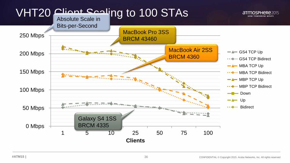
VHT20 Client Scaling to 100 STAs
0 Mbps
50 Mbps
100 Mbps
150 Mbps
200 Mbps
250 Mbps
1 5 10 25 50 75 100
Clients
GS4 TCP Up
GS4 TCP Bidirect
MBA TCP Up
MBA TCP Bidirect
MBP TCP Up
MBP TCP Bidirect
Down
Up
Bidirect
MacBook Pro 3SS
BRCM 43460
MacBook Air 2SS
BRCM 4360
Galaxy S4 1SS
BRCM 4335
Absolute Scale in
Bits-per-Second

37 CONFIDENTIAL © Copyright 2015. Aruba Networks, Inc. All rights reserved#ATM15 |
Straw Poll #1
Is anyone surprised that capacity
is inversely proportional to client count?

38 CONFIDENTIAL © Copyright 2015. Aruba Networks, Inc. All rights reserved#ATM15 |
Straw Poll #2
What is the primary explanation for the drop?
1. Collisions & retries
2. Rate adaptation
3. MAC layer operation
4. Higgs boson

39 CONFIDENTIAL © Copyright 2015. Aruba Networks, Inc. All rights reserved#ATM15 |
MIMO Works!
0%
20%
40%
60%
80%
100%
120%
1 5 10 25 50 75 100
Th
rou
gh
pu
t (%
)
Clients
GS4 TCP Up
GS4 TCP Bidirect
MBA TCP Up
MBA TCP Bidirect
MBP TCP Up
MBP TCP Bidirect
Down
Up
Bidirect
Normalized to
3SS = 1
2SS is about 66%
across the range
1SS is about 33%
across the range
Relative Scale
in Percent
40 CONFIDENTIAL © Copyright 2015. Aruba Networks, Inc. All rights reserved#ATM15 |
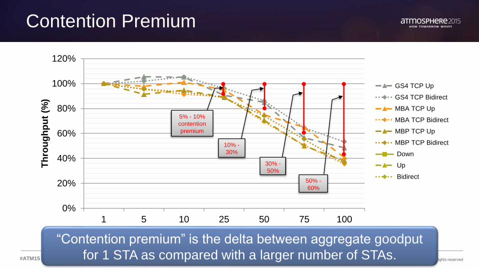
Contention Premium
0%
20%
40%
60%
80%
100%
120%
1 5 10 25 50 75 100
Th
rou
gh
pu
t (%
)
Clients
GS4 TCP Up
GS4 TCP Bidirect
MBA TCP Up
MBA TCP Bidirect
MBP TCP Up
MBP TCP Bidirect
Down
Up
Bidirect
5% - 10%
contention
premium
30% -
50%
50% -
60%
10% -
30%
“Contention premium” is the delta between aggregate goodput
for 1 STA as compared with a larger number of STAs.

41 CONFIDENTIAL © Copyright 2015. Aruba Networks, Inc. All rights reserved#ATM15 |
Is It Inevitable?
• CP is a fundamental property of 802.11• Capacity losses are expected with CSMA-based contention
• Or is it?
• Why should cutting the pie into more slices shrink the pie by nearly 60%?
• Why would there be significantly higher collisions in a clean test environment with a single BSS and a well ordered channel?
• And why is the drop so similar for a 3SS laptop that can move over 3X the data in the same airtime as a 1SS smartphone?

42 CONFIDENTIAL © Copyright 2015. Aruba Networks, Inc. All rights reserved#ATM15 |
Retries Are Not A Major Cause
0%
10%
20%
30%
40%
50%
60%
70%
80%
90%
100%
1 25 50 75 100Retry Packets Non-Retry
MBA 2SS, TCP Up, AP-225, 20-MHz
0%
10%
20%
30%
40%
50%
60%
70%
80%
90%
100%
1 30 50 75 100Retry Packets Non-Retry
MBA 2SS, TCP Down, AP-135, 40-MHz
Retries are well
under 10% of
frames They do not
grow
Same behavior with
802.11n AP, different
channel width, different
direction
43 CONFIDENTIAL © Copyright 2015. Aruba Networks, Inc. All rights reserved#ATM15 |
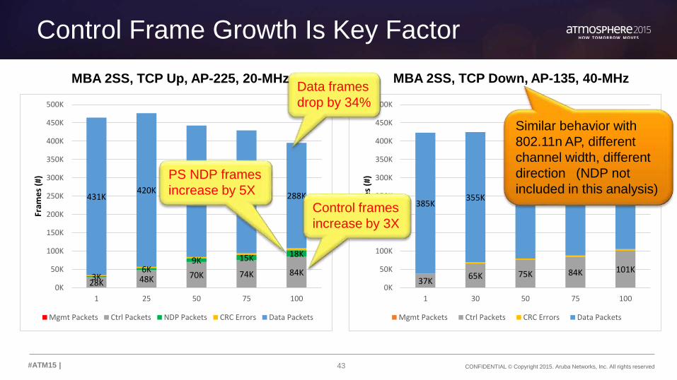
Control Frame Growth Is Key Factor
28K 48K 70K 74K 84K3K6K
9K 15K 18K
431K420K 359K 335K 288K
0K
50K
100K
150K
200K
250K
300K
350K
400K
450K
500K
1 25 50 75 100
Fram
es
(#)
Mgmt Packets Ctrl Packets NDP Packets CRC Errors Data Packets
37K65K 75K 84K 101K
385K355K 352K 338K 326K
0K
50K
100K
150K
200K
250K
300K
350K
400K
450K
500K
1 30 50 75 100
Fram
es
(#)
Mgmt Packets Ctrl Packets CRC Errors Data Packets
Data frames
drop by 34%
MBA 2SS, TCP Up, AP-225, 20-MHz MBA 2SS, TCP Down, AP-135, 40-MHz
Control frames
increase by 3X
PS NDP frames
increase by 5X
Similar behavior with
802.11n AP, different
channel width, different
direction (NDP not
included in this analysis)
44 CONFIDENTIAL © Copyright 2015. Aruba Networks, Inc. All rights reserved#ATM15 |
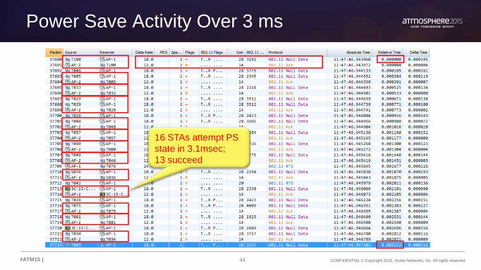
Power Save Activity Over 3 ms
16 STAs attempt PS
state in 3.1msec;
13 succeed

45 CONFIDENTIAL © Copyright 2015. Aruba Networks, Inc. All rights reserved#ATM15 |
Average Frame Size Decreases With Load
0K
50K
100K
150K
200K
250K
300K
350K
400K
450K
500K
1 25 50 75 100
Fra
mes (
#)
>=2347
2048-2346
1024-2047
512-1023
256-511
128-255
64-127
<64
MBA 2SS, TCP Up, AP-225, 20-MHz
TCP Data
TCP Ack
Control Frames
0%
10%
20%
30%
40%
50%
60%
70%
80%
90%
100%
1 25 50 75 100
Fra
mes (
#)
>=2347
2048-2346
1024-2047
512-1023
256-511
128-255
64-127
<64

46 CONFIDENTIAL © Copyright 2015. Aruba Networks, Inc. All rights reserved#ATM15 |
0%
10%
20%
30%
40%
50%
60%
70%
80%
90%
100%
1 25 50 75 100
What Is Driving The Control Frame Growth?
NDP NDP NDPNDP NDPRTS
RTS
RTS
RTSRTS
CTS
CTS
CTS
CTS
CTS
BA
BA
BABA
BA
Ack
Ack
Ack
Ack
Ack
0K
10K
20K
30K
40K
50K
60K
70K
80K
90K
100K
1 25 50 75 100
Fram
es
(#)
MBA 2SS, TCP Up, AP-225, 20-MHz3X more TXOPs =
Poor A-MPDU
packing efficiency
ACKs are for NDPs.
Combined total grows
from 6.4K 34.2K
NDP
RTS
CTS
BA
Ack
Preceded by
SIFS (16usec)
Preceded by full
arbitration (43usec
AIFS + EDCA CW)

47 CONFIDENTIAL © Copyright 2015. Aruba Networks, Inc. All rights reserved#ATM15 |
Rate Adaptation Is Not A Major Contributor
0K
50K
100K
150K
200K
250K
300K
350K
400K
450K
500K
1 25 50 75 100
Fram
es
(#)
173.3 Mbps
130 Mbps
117 Mbps
115.5 Mbps
104 Mbps
86.5 Mbps
78 Mbps
72 Mbps
39 Mbps
24 Mbps
18 Mbps
12 Mbps
6 Mbps
Rate adaptation
on data frames
NDPs @ 18Mbps
Acks @ 12Mbps

48 CONFIDENTIAL © Copyright 2015. Aruba Networks, Inc. All rights reserved#ATM15 |
Contention Premium Summary
• The principal mechanism behind the contention premium is MAC layer overhead growing with STA count.• Decreased A-MPDU packing efficiency
• More TXOPs due to more STAs contending
• Airtime efficiency of each TXOP decreases
• Power save NDP/Ack growth due to elevated TXOP activity level
For any given number of STAs, it is better to divide them
across more small channels to minimize this effect.

49 CONFIDENTIAL © Copyright 2015. Aruba Networks, Inc. All rights reserved#ATM15 |
Contention Premium Explains the 80/40/20 Result
0 Mbps
50 Mbps
100 Mbps
150 Mbps
200 Mbps
250 Mbps
300 Mbps
5 10 25 50 75 100
Clients
VHT20x4 Up
VHT20x4 Bidirect
VHT40x2 Up
VHT40x2 Bidirect
VHT80x1 Up
VHT80x1 Bidirect
Down
Up
Bidirect
Contention
premium for 100
STAs/channel is
50-60%
C.P. for 50 STAs
per channel is
10-30%
C.P. for 25 STAs
per channel is just
5-10%

50#ATM15 |
Understanding 802.11 TXOP Airtime Usage
51 CONFIDENTIAL © Copyright 2015. Aruba Networks, Inc. All rights reserved#ATM15 |
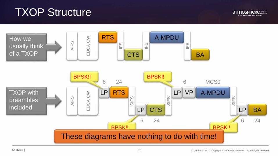
How we
usually think
of a TXOP
TXOP Structure
RTS
CTS
LP
A-MPDU
BA
IFS
IFS
IFS
AIF
S
ED
CA
CW
RTS
CTS
A-MPDU
BA
SIF
S
SIF
S
SIF
S
AIF
S
ED
CA
CW
LP
LP VP
6 24
6 24 6 24
6 MCS9
TXOP with
preambles
included
BPSK!! BPSK!!
BPSK!! BPSK!!
LP
These diagrams have nothing to do with time!

52 CONFIDENTIAL © Copyright 2015. Aruba Networks, Inc. All rights reserved#ATM15 |
TXOP Scaled to Time (173.3 Mbps Rate)
90 byte
A-MPDU
(TCP ack)
Arbitration
49.6%
Payload
13.2%
RTS/CTS
23.7%
BA
13.5%
3,000 byte
A-MPDU
(TCP data)
Even with 3K
frame, payload
is only 27.6%.
VHT preamble
is another 8.8%
Best case scenario with no retries.
Retries & collisions significantly
degrade the payload airtime share.

53 CONFIDENTIAL © Copyright 2015. Aruba Networks, Inc. All rights reserved#ATM15 |
TXOP Time Breakdown (173.3Mbps Rate)
MAC UnitPayload
BytesPayload
BitsData Rate
(Mbps) Usec% Airtimew/CSMA
%AirtimeTXOP Only
AIFS[BE] 43 11.7%
CW[BE] 140 37.9%
Legacy Preamble 20 5.4% 10.8%
RTS 20 160 18 9 2.4% 4.8%
SIFS 16 4.3% 8.6%
Legacy Preamble 20 5.4% 10.8%
CTS 14 112 18 6 1.7% 3.4%
SIFS 16 4.3% 8.6%
VHT Preamble 44 12.0% 23.7%
1st A-MPDU Delimiter 4 32 173.3 0 0.1% 0.1%
1st A-MPDU 90 720 173.3 4 1.1% 2.2%
SIFS 16 4.3% 8.6%
Legacy Preamble 20 5.4% 10.8%
BA 32 256 18 14 3.9% 7.7%
Total Airtime including CSMA 1280 368 100.0% 100.0%
Airtime for TXOP only 186
Effective TXOP Rate (Mbps) including CSMA 3.5
Effective TXOP Rate (Mbps) for TXOP only 6.9
MAC UnitPayload
BytesPayload
BitsData Rate
(Mbps) Usec% Airtimew/CSMA
%AirtimeTXOP Only
AIFS[BE] 43 8.6%
CW[BE] 140 27.8%
Legacy Preamble 20 4.0% 6.2%
RTS 20 160 18 9 1.8% 2.8%
SIFS 16 3.2% 5.0%
Legacy Preamble 20 4.0% 6.2%
CTS 14 112 18 6 1.2% 1.9%
SIFS 16 3.2% 5.0%
VHT Preamble 44 8.8% 13.7%
1st A-MPDU Delimiter 4 32 173.3 0 0.0% 0.1%
1st A-MPDU 3000 24000 173.3 138 27.6% 43.3%
SIFS 16 3.2% 5.0%
Legacy Preamble 20 4.0% 6.2%
BA 32 256 18 14 2.8% 4.4%
Total Airtime including CSMA 24560 503 100.0% 100.0%
Airtime for TXOP only 320
Effective TXOP Rate (Mbps) including CSMA 48.9
Effective TXOP Rate (Mbps) for TXOP only 76.7
90 Byte A-MPDU 3,000 Byte A-MPDU
Payload is
1.2% without
the preamble
Arbitration is 49.6%
using default
CWmin[BE]
The “effective” data
rate for the TXOP
is just 3.5Mbps
Payload
increases to
27.6%
Faster rates
reduce
airtime
TXOP effective rate
is just 28% of the
payload rate!!

54 CONFIDENTIAL © Copyright 2015. Aruba Networks, Inc. All rights reserved#ATM15 |
TXOP Scaled to Time (866.7 Mbps Rate)
- 500 1,000 1,500 2,000 2,500 3,000 3,500
AIFS+CW[BE]183us
RTS+CTS87us
VHT Preamble &A-MPDU2,707us
----BA
50us
A-MPDU of
64 x 4,500B
MPDUs
Arbitration
6%
Payload
89.4%
RTS/CTS
2.9%
BA
1.7%
By design, the 802.11 MAC only achieves
high efficiency with large A-MPDUs

55 CONFIDENTIAL © Copyright 2015. Aruba Networks, Inc. All rights reserved#ATM15 |
Typical Frame Size – Office Environment
30 minute capture, 6 Channels >80% of
frames
under 256B

56 CONFIDENTIAL © Copyright 2015. Aruba Networks, Inc. All rights reserved#ATM15 |
Typical Frame Size – Office Environment
30 minute capture, 6 Channels
>80% of
frames
under 256B
<5% of
frames over
1KB
>80% of
frames
under 256B
<15% of
frames over
512B

57 CONFIDENTIAL © Copyright 2015. Aruba Networks, Inc. All rights reserved#ATM15 |
Typical Frame Sizes – Football Stadium
10 minute capture, 7 Channels

58 CONFIDENTIAL © Copyright 2015. Aruba Networks, Inc. All rights reserved#ATM15 |
Typical Frame Types – Football Stadium
10 minute capture, 7 Channels
60% are
control
frames
23% are
data frames

59 CONFIDENTIAL © Copyright 2015. Aruba Networks, Inc. All rights reserved#ATM15 |
Importance of Maximizing Payload Data Rates
• VHT preambles consume as much or more airtime for common TCP frame sizes
• Even large frames at 80-MHz rates barely equal the VHT preamble time
• Retries are expensive
1SS VHT20
must be >500B
to equal
preamble time
Preamble time
blows away
payload time for
all small packets
MPDU must be
>=3KB to match
preamble time

60 CONFIDENTIAL © Copyright 2015. Aruba Networks, Inc. All rights reserved#ATM15 |
Importance of Reducing Control & Mgmt Rates
• Increasing minimum rate can greatly reduce airtime used by control frames
• Multiplier effect at high STA counts due to control frame growth

61 CONFIDENTIAL © Copyright 2015. Aruba Networks, Inc. All rights reserved#ATM15 |
Effect of Beacon Rates in High-BSSID Facilities
1 2 3
1 0.44% 0.89% 1.33%
5 2.22% 4.44% 6.67%
10 4.44% 8.89% 13.33%
15 6.67% 13.33% 20.00%
20 8.89% 17.77% 26.66%
25 11.11% 22.22% 33.33%
30 13.33% 26.66% 39.99%
35 15.55% 31.10% 46.66%
40 17.77% 35.55% 53.32%
45 20.00% 39.99% 59.99%
50 22.22% 44.43% 66.65%
APs per
Channel
Number of SSIDs
1 2 3
1 0.19% 0.38% 0.57%
5 0.95% 1.90% 2.86%
10 1.90% 3.81% 5.71%
15 2.86% 5.71% 8.57%
20 3.81% 7.62% 11.43%
25 4.76% 9.52% 14.28%
30 5.71% 11.43% 17.14%
35 6.67% 13.33% 20.00%
40 7.62% 15.23% 22.85%
45 8.57% 17.14% 25.71%
50 9.52% 19.04% 28.56%
APs per
Channel
Number of SSIDs
1 2 3
1 0.16% 0.32% 0.48%
5 0.80% 1.59% 2.39%
10 1.59% 3.18% 4.78%
15 2.39% 4.78% 7.16%
20 3.18% 6.37% 9.55%
25 3.98% 7.96% 11.94%
30 4.78% 9.55% 14.33%
35 5.57% 11.14% 16.71%
40 6.37% 12.73% 19.10%
45 7.16% 14.33% 21.49%
50 7.96% 15.92% 23.88%
APs per
Channel
Number of SSIDs
1 2 3
1 0.13% 0.26% 0.38%
5 0.64% 1.28% 1.92%
10 1.28% 2.56% 3.84%
15 1.92% 3.84% 5.76%
20 2.56% 5.12% 7.68%
25 3.20% 6.40% 9.59%
30 3.84% 7.68% 11.51%
35 4.48% 8.96% 13.43%
40 5.12% 10.23% 15.35%
45 5.76% 11.51% 17.27%
50 6.40% 12.79% 19.19%
APs per
Channel
Number of SSIDs
Revolution Wi-Fi Capacity Planner, http://www.revolutionwifi.net/capacity-planner. Reprinted with permission.
6 Mbps Beacon Rate 18 Mbps Beacon Rate 24 Mbps Beacon Rate 36 Mbps Beacon Rate

62#ATM15 |
Collision Domains & RF Spectrum Reuse

63 CONFIDENTIAL © Copyright 2015. Aruba Networks, Inc. All rights reserved#ATM15 |
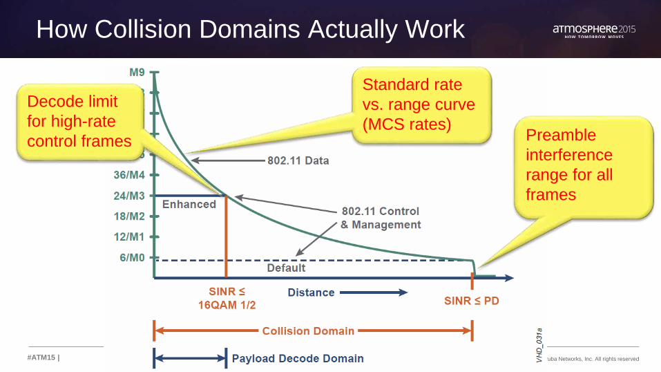
What Is A Collision Domain?
• A physical area in which 802.11 devices attempting to send can decode one another’s frame preambles.
• A moment in time. • Two nearby stations on the same channel will not collide if they
send at different times.
• Dynamic regions that are constantly moving in space and time based on which devices are transmitting
A collision domain is therefore an independent
block of capacity in an 802.11 system.

64 CONFIDENTIAL © Copyright 2015. Aruba Networks, Inc. All rights reserved#ATM15 |
How We Normally Draw Collision Domains
Typical cell diagram showing radius of cell edge
65 CONFIDENTIAL © Copyright 2015. Aruba Networks, Inc. All rights reserved#ATM15 |
How Collision Domains Actually Work
Standard rate
vs. range curve
(MCS rates)
Decode limit
for high-rate
control frames Preamble
interference
range for all
frames

66 CONFIDENTIAL © Copyright 2015. Aruba Networks, Inc. All rights reserved#ATM15 |
Preamble Interference Radius Is HUGE

67#ATM15 |
Summary & Review

68 CONFIDENTIAL © Copyright 2015. Aruba Networks, Inc. All rights reserved#ATM15 |
Summary – Maximizing VHD Capacity
• Use every possible channel
20-MHz channel width + DFS
• Spread the clients evenly across all the channels
RF design / Steering features
• Maximize rates of repetitive frame types
Trim low basic & TX rates / Raise beacon rates / unicast conversion
• Facilitate aggregation
Jumbo frames / Increase A-MSDU / Increase TCP window sizes
• Eliminate unnecessary TX/RX
Broadcast-multicast filters / Probe filtering / RX sensitivity tuning
• Use top-down capacity planning to force a system-level viewpoint

69 CONFIDENTIAL © Copyright 2015. Aruba Networks, Inc. All rights reserved#ATM15 |
Sign up, save $200!
arubanetworks.com/atmosphere2016
Give feedback!
… Before You Go
atmosphere
2016

THANK YOU
70#ATM15 | @ArubaNetworks