high availability wan implementation with mpls to … · 2017-11-06 · associates vrf along to the...
TRANSCRIPT
Abstract—This project was developed to offer high
availability system to headquarter offices of a financial
institution in order to guarantee communication continuity
with their branches. The main objectives was to minimize
service time due to link failures and to provide redundancy in
data links from each branch to the main communication center
with the support of two different providers. A secondary
objective was to use both links providers simultaneously for
symmetrical traffic balance, using them at the same time and by
demand. This project was a useful reference guide for both
links providers for similar requirements of new clients.
Index Terms—EIGRP, HSRP, MPLS, Routing protocols.
I. INTRODUCTION
HE client is a financial institution with branches across a
region, reason why it depends on the
telecommunications links among branches with its main
communication center. The project pursued to reduce at a
minimum level the lost connection to guarantee service
provision.
The proposal consisted in connect every main branches by
two links with different telecommunications providers with
Multiprotocol Label Switching (MPLS) and Enhanced
Interior Gateway Routing Protocol (EIGRP) to perform a
high availability Wide Area Network (WAN). MPLS was
employed for traffic managing in the providers transport
network [1][2]. EIGRP was employed for dynamic routing
in the client network and for traffic balancing among each
branch with the links of the two providers [3][4]. In addition,
Hot Standing Routing Protocol (HSRP) was used to
configure redundancy in both links and devices at the main
communication center [3][5][6].
Manuscript received April 25, 2017.
J. A. Peralta is a network engineer and co-founder of Socio Digital
Services Agency, Guayaquil, Ecuador. Phone: +593-9-87827765, +593-9-
99092329 (e-mail: [email protected]).
V. Sanchez Padilla is with ESPOL Polytechnic University, Escuela
Superior Politécnica del Litoral, ESPOL, Faculty of Electrical and
Computer Engineering, Campus Gustavo Galindo Km 30.5 Vía Perimetral,
P.O. Box 09-01-5863, Guayaquil, Ecuador. Phone: +593-4-2269985 (e-
mail: [email protected]).
J. Rodriguez Espinoza was with ESPOL Polytechnic University,
Escuela Superior Politécnica del Litoral, ESPOL, Telematics Engineering
Program, Campus Gustavo Galindo Km 30.5 Vía Perimetral, P.O. Box 09-
01-5863, Guayaquil, Ecuador. Phone: +593-9-84615430 (e-mail:
II. CLIENT REQUIREMENTS
The Institution decided to engage links with two providers
with the following characteristics:
Definition of a main communication center, an
alternative communication center, and eleven
branches (main branches and secondary branches).
Symmetrical 2 Mbps bandwidth.
A link must connect the main communication center.
In case of failure, a backup option among each
branch with an alternative communication center
should be available with the same symmetrical
bandwidth of 2 Mbps.
Each branch should have a traffic balance between
the two providers symmetrically. This means,
bandwidth consumption graphic of one of the
providers (main provider) must be identical to the
traffic consumption done by the other provider
(secondary provider). This will allow up to have a
maximum traffic consumption of 4 Mbps from each
branch, adding the allowed bandwidth by the
providers.
Configure a dynamic routing protocol to guarantee
faster convergence in case of any incident during
transmission.
In each branch, providers should install one last mile
connected to an interface of the router deployed.
Links deployments by providers at a physical level
were a task of both Logistic and Planning
departments. Deployments run while WAN design is
executing.
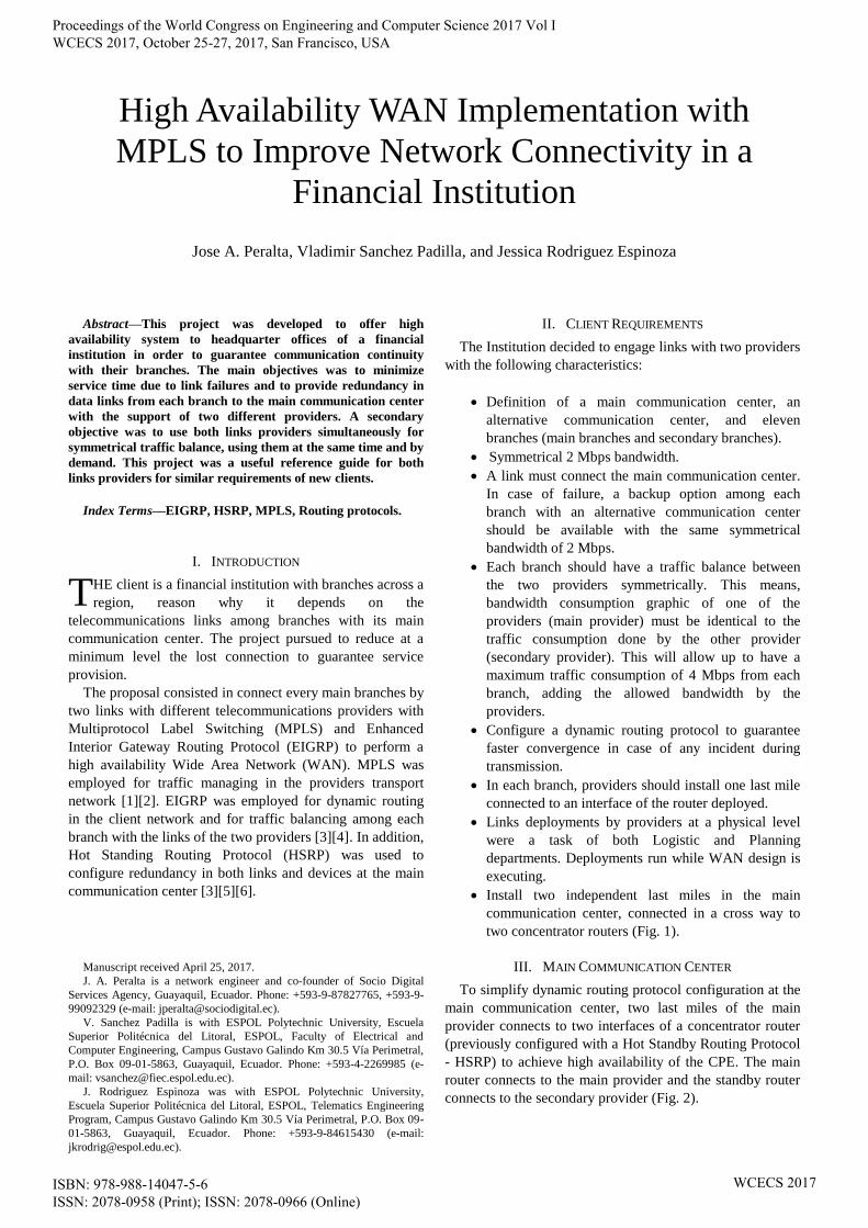
Install two independent last miles in the main
communication center, connected in a cross way to
two concentrator routers (Fig. 1).
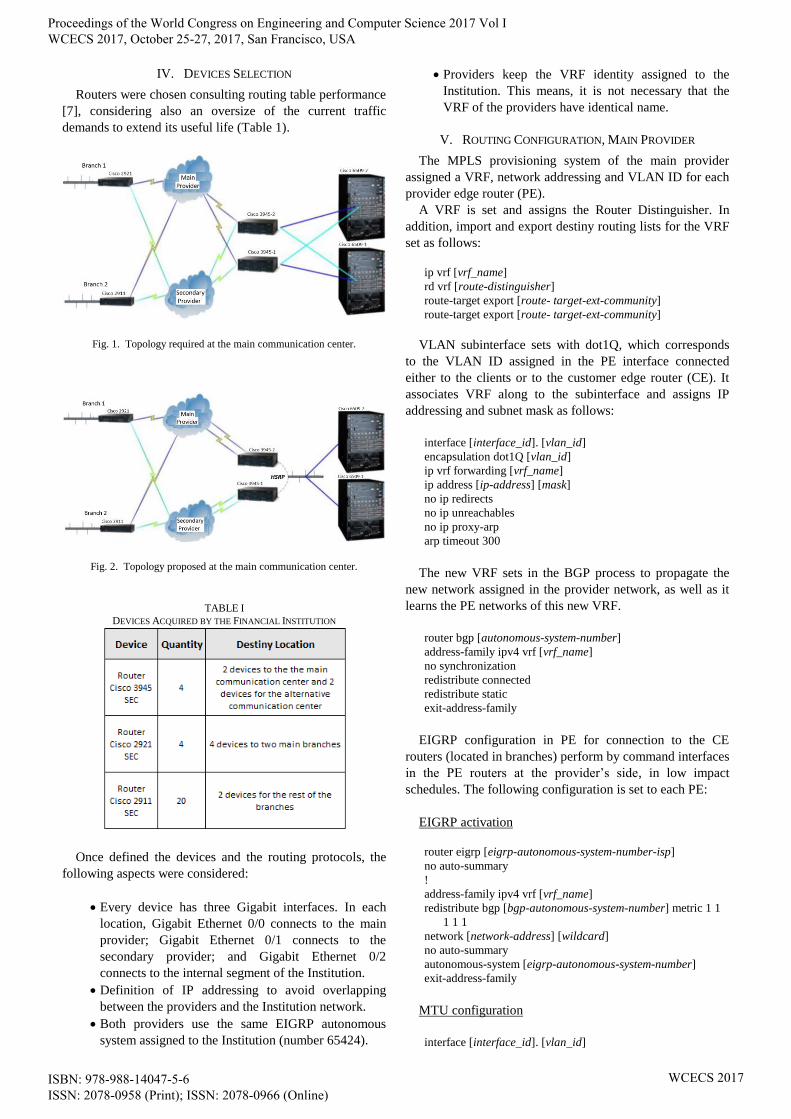
III. MAIN COMMUNICATION CENTER
To simplify dynamic routing protocol configuration at the
main communication center, two last miles of the main
provider connects to two interfaces of a concentrator router
(previously configured with a Hot Standby Routing Protocol
- HSRP) to achieve high availability of the CPE. The main
router connects to the main provider and the standby router
connects to the secondary provider (Fig. 2).
High Availability WAN Implementation with
MPLS to Improve Network Connectivity in a
Financial Institution
Jose A. Peralta, Vladimir Sanchez Padilla, and Jessica Rodriguez Espinoza
T
Proceedings of the World Congress on Engineering and Computer Science 2017 Vol I WCECS 2017, October 25-27, 2017, San Francisco, USA
ISBN: 978-988-14047-5-6 ISSN: 2078-0958 (Print); ISSN: 2078-0966 (Online)
WCECS 2017
IV. DEVICES SELECTION
Routers were chosen consulting routing table performance
[7], considering also an oversize of the current traffic
demands to extend its useful life (Table 1).
Fig. 1. Topology required at the main communication center.
Fig. 2. Topology proposed at the main communication center.
TABLE I
DEVICES ACQUIRED BY THE FINANCIAL INSTITUTION
Once defined the devices and the routing protocols, the
following aspects were considered:
Every device has three Gigabit interfaces. In each
location, Gigabit Ethernet 0/0 connects to the main
provider; Gigabit Ethernet 0/1 connects to the
secondary provider; and Gigabit Ethernet 0/2
connects to the internal segment of the Institution.
Definition of IP addressing to avoid overlapping
between the providers and the Institution network.
Both providers use the same EIGRP autonomous
system assigned to the Institution (number 65424).
Providers keep the VRF identity assigned to the
Institution. This means, it is not necessary that the
VRF of the providers have identical name.
V. ROUTING CONFIGURATION, MAIN PROVIDER
The MPLS provisioning system of the main provider
assigned a VRF, network addressing and VLAN ID for each
provider edge router (PE).
A VRF is set and assigns the Router Distinguisher. In
addition, import and export destiny routing lists for the VRF
set as follows:
ip vrf [vrf_name]
rd vrf [route-distinguisher]
route-target export [route- target-ext-community]
route-target export [route- target-ext-community]
VLAN subinterface sets with dot1Q, which corresponds
to the VLAN ID assigned in the PE interface connected
either to the clients or to the customer edge router (CE). It
associates VRF along to the subinterface and assigns IP
addressing and subnet mask as follows:
interface [interface_id]. [vlan_id]
encapsulation dot1Q [vlan_id]
ip vrf forwarding [vrf_name]
ip address [ip-address] [mask]
no ip redirects
no ip unreachables
no ip proxy-arp
arp timeout 300
The new VRF sets in the BGP process to propagate the
new network assigned in the provider network, as well as it
learns the PE networks of this new VRF.
router bgp [autonomous-system-number]
address-family ipv4 vrf [vrf_name]
no synchronization
redistribute connected
redistribute static
exit-address-family
EIGRP configuration in PE for connection to the CE
routers (located in branches) perform by command interfaces
in the PE routers at the provider’s side, in low impact
schedules. The following configuration is set to each PE:
EIGRP activation
router eigrp [eigrp-autonomous-system-number-isp]
no auto-summary
!
address-family ipv4 vrf [vrf_name]
redistribute bgp [bgp-autonomous-system-number] metric 1 1
1 1 1
network [network-address] [wildcard]
no auto-summary
autonomous-system [eigrp-autonomous-system-number]
exit-address-family
MTU configuration
interface [interface_id]. [vlan_id]
Proceedings of the World Congress on Engineering and Computer Science 2017 Vol I WCECS 2017, October 25-27, 2017, San Francisco, USA
ISBN: 978-988-14047-5-6 ISSN: 2078-0958 (Print); ISSN: 2078-0966 (Online)
WCECS 2017
encapsulation dot1Q [vlan_id]
ip vrf forwarding [vrf_name]
ip address [ip-address] [mask]
no ip redirects
no ip unreachables
no ip proxy-arp
ip mtu 1500
arp timeout 300
The following commands set redistribution of learned
routes by EIGRP inside BGP, and allowed to every PE of
the main provider enabling dynamic routing protocol with
every CE located in the branches:
router bgp [bgp-autonomous-system-number]
address-family ipv4 vrf [vrf_name]
no synchronization
redistribute connected
redistribute static
redistribute eigrp [eigrp-autonomous-system-number]
no auto-summary
no synchronization
exit-address-family
VI. ROUTER INSTALLATION AND CONFIGURATION TESTS IN
THE PILOT BRANCH
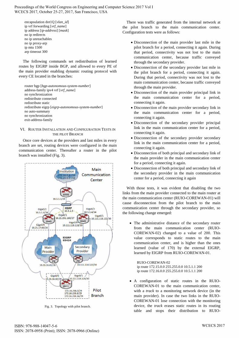
Once core devices at the providers and last miles in every
branch are set, routing devices were configured in the main
communication center. Thereafter a router in the pilot
branch was installed (Fig. 3).
Fig. 3. Topology with pilot branch.
There was traffic generated from the internal network at
the pilot branch to the main communication center.
Configuration tests were as follows:
Disconnection of the main provider last mile in the
pilot branch for a period, connecting it again. During
that period, connectivity was not lost to the main
communication center, because traffic conveyed
through the secondary provider.
Disconnection of the secondary provider last mile in
the pilot branch for a period, connecting it again.
During that period, connectivity was not lost to the
main communication center, because traffic conveyed
through the main provider.
Disconnection of the main provider principal link in
the main communication center for a period,
connecting it again.
Disconnection of the main provider secondary link in
the main communication center for a period,
connecting it again.
Disconnection of the secondary provider principal
link in the main communication center for a period,
connecting it again.
Disconnection of the secondary provider secondary
link in the main communication center for a period,
connecting it again.
Disconnection of both principal and secondary link of
the main provider in the main communication center
for a period, connecting it again.
Disconnection of both principal and secondary link of
the secondary provider in the main communication
center for a period, connecting it again
With those tests, it was evident that disabling the two
links from the main provider connected to the main router at
the main communication center (RUIO-COREWAN-01) will
cause disconnection from the pilot branch to the main
communication center through the secondary provider, so
the following change emerged:
The administrative distance of the secondary router
from the main communication center (RUIO-
COREWAN-02) changed to a value of 200. This
value corresponds to static routes to the main
communication center, and is higher than the ones
learned (value of 170) by the external EIGRP,
learned by EIGRP from RUIO-COREWAN-01.
RUIO-COREWAN-02
ip route 172.15.0.0 255.255.0.0 10.5.1.1 200
ip route 172.16.0.0 255.255.0.0 10.5.1.1 200
A configuration of static routes in the RUIO-
COREWAN-01 to the main communication center,
with a track to a monitoring network device (in the
main provider). In case the two links in the RUIO-
COREWAN-01 lose connection with the monitoring
device, the track erases static routes in its routing
table and stops their distribution to RUIO-
Proceedings of the World Congress on Engineering and Computer Science 2017 Vol I WCECS 2017, October 25-27, 2017, San Francisco, USA
ISBN: 978-988-14047-5-6 ISSN: 2078-0958 (Print); ISSN: 2078-0966 (Online)
WCECS 2017

COREWAN-02, learning static routes with an
administrative distance of 200.
RUIO-COREWAN-01
ip route 172.15.0.0 255.255.0.0 10.5.1.1 track 1
ip route 172.16.0.0 255.255.0.0 10.5.1.1 track 1
¡
ip sla 1
icmp-echo 201.218.38.7
threshold 2
frequency 5
ip sla schedule 1 life forever start-time now
Traffic balance achievement was not possible in the pilot
branch through its two symmetrical links.
GigabitEthernet0/2 assigned a defined metric to incoming
traffic (with an access list command). Adding the following
commands in EIGRP process allowed matching both routing
metrics and administrative distance learned by EIGRP, in
order to achieve symmetrical traffic balance:
router eigrp 65424
distribute-list route-map METRIC in GigabitEthernet0/2
distribute-list route-map METRIC in GigabitEthernet0/0.113
offset-list 50 in 20000000 GigabitEthernet0/1.115
!
access-list 50 permit any
!
route-map METRIC permit 10
match ip address 50
set metric 2048 100 255 1 1500
Once accomplished the requirements, next steps were to
install and configure routers in the other branches, including
remote technical support. Fig. 4 depicts network topology
after configurations.
Fig. 4. Topology with all the branches involved.
VII. ALTERNATIVE COMMUNICATION CENTER
The alternative communication center runs when
connection shutdowns in the main communication center
with both main provider and secondary provider. It has the
same segment of the main communication center
(172.15.0.0/16 and 172.16.0.0/16).
CE router learns EIGRP routes in normal conditions from
both providers’ networks with an administrative distance of
170 and with static routes with administrative distance of
200 to main communication center network, but to a router
of the internal network of the alternative communication
center. Thus, when the router lost connectivity with the
segment 172.15.0.0/16 and 172.16.0.0/16, through the main
communication center learns static routes with
administrative distance of 200 and propagates them to the
EIGRP process through both providers’ networks in order
branches learn automatically a new path to convey
information through the alternative communication center.
VIII. CONCLUSIONS
It was possible to optimize learning processes in
communication links due to an Active-Active configuration,
conveying traffic across branches simultaneously through
both links in each provider.
MPLS improved routing, as traffic between two branches
did not direct towards the main communication center, but
directed toward branches through providers networks.
EIGRP over MPLS providers’ networks allowed
configuring an automatic connection to the alternative
communication center when the EIGRP process stops
propagation from the main communication center networks
and starts learning from the alternative communication
center.
REFERENCES
[1] L.D. Ghein, MPLS Fundamentals. Cisco, 2010.
[2] B. Morgan and N. Lovering, CCNP ISCW Official Exam
Certification Guide. Cisco Press, 2008.
[3] Cisco System Inc., Protocolo de Enrutamiento de Gateway Interior
Mejorado, [Online]. Available:
www.cisco.com/cisco/web/support/LA/7/75/75043_eigrp-toc.pdf
[4] D. Teare and C. Paquet, Building Scalable Cisco Internetworks
(BSCI). Cisco Press, 2010.
[5] K. Ameen, Providing Redundancy Procedure at the Network Layer
using HSRP and VRRP Protocols. S.I.: Authorhouse, 2016.
[6] D. Hucaby, CCNP BCMSN Exam Certification Guide: CCNP Self-
Study. Cisco Press, 2008.
[7] Cisco Systems Inc., Routing Performance, [Online]. Available:
http://www.cisco.com/web/partners/downloads/765/tools/quickrefere
nce/routerperformance.pdf
Proceedings of the World Congress on Engineering and Computer Science 2017 Vol I WCECS 2017, October 25-27, 2017, San Francisco, USA
ISBN: 978-988-14047-5-6 ISSN: 2078-0958 (Print); ISSN: 2078-0966 (Online)
WCECS 2017