high availability implementation of filenet p8
DESCRIPTION
High Availability Implementation Of FileNet P8TRANSCRIPT
ibm.com/redbooks
IBM High Availability Solutionfor IBM FileNet P8 Systems
Provides HA strategies and options for IBM FileNet P8 systems
Includes HA implementation for Content Engine, Process Engine, and Application Engine
Describes HA implementation for Content Search Engine, Image Services, and databases
Front cover
Wei-Dong ZhuWhei-Jen ChenScott BramanAndrea CalfurniJesse F ChenJesse C Clem
Cristina Y. DoiAtul V. GoreJochen KerscherTim MorganAndrei Socoliuc

IBM High Availability Solution for IBM FileNet P8 Systems
August 2009
International Technical Support Organization
SG24-7700-00

© Copyright International Business Machines Corporation 2009. All rights reserved.Note to U.S. Government Users Restricted Rights -- Use, duplication or disclosure restricted by GSA ADPSchedule Contract with IBM Corp.
First Edition (August 2009)
This edition applies to Version 4.0 of IBM FileNet Content Manager (product number 5724-R81), Version 4.0 of IBM FileNet Business Process Manager (product number 5724-R76), and Version 4.1.2 IBM FileNet Image Services (5724-R95).
Note: Before using this information and the product it supports, read the information in “Notices” on page ix.
Contents
Notices . . . . . . . . . . . . . . . . . . . . . . . . . . . . . . . . . . . . . . . . . . . . . . . . . . . . . . . ixTrademarks . . . . . . . . . . . . . . . . . . . . . . . . . . . . . . . . . . . . . . . . . . . . . . . . . . . . x
Preface . . . . . . . . . . . . . . . . . . . . . . . . . . . . . . . . . . . . . . . . . . . . . . . . . . . . . . . xiThe team who wrote this book . . . . . . . . . . . . . . . . . . . . . . . . . . . . . . . . . . . . . xiiBecome a published author . . . . . . . . . . . . . . . . . . . . . . . . . . . . . . . . . . . . . . . xvComments welcome. . . . . . . . . . . . . . . . . . . . . . . . . . . . . . . . . . . . . . . . . . . . . xv
Part 1. Concepts and overview . . . . . . . . . . . . . . . . . . . . . . . . . . . . . . . . . . . . . . . . . . . . . . . . 1
Chapter 1. Introducing high availability . . . . . . . . . . . . . . . . . . . . . . . . . . . . 31.1 High availability . . . . . . . . . . . . . . . . . . . . . . . . . . . . . . . . . . . . . . . . . . . . . . 41.2 Measuring availability . . . . . . . . . . . . . . . . . . . . . . . . . . . . . . . . . . . . . . . . . 4
1.2.1 Planned compared to unplanned outages . . . . . . . . . . . . . . . . . . . . . 51.2.2 Availability matrix . . . . . . . . . . . . . . . . . . . . . . . . . . . . . . . . . . . . . . . . 61.2.3 Total availability of a system . . . . . . . . . . . . . . . . . . . . . . . . . . . . . . . . 7
1.3 Levels of availability . . . . . . . . . . . . . . . . . . . . . . . . . . . . . . . . . . . . . . . . . . 81.4 High availability cost compared to loss . . . . . . . . . . . . . . . . . . . . . . . . . . . 111.5 High availability and continuous availability . . . . . . . . . . . . . . . . . . . . . . . 121.6 IBM FileNet P8 platform infrastructure fundamentals . . . . . . . . . . . . . . . . 13
1.6.1 Application clustering (server farms). . . . . . . . . . . . . . . . . . . . . . . . . 161.6.2 Platform clustering (server clusters) . . . . . . . . . . . . . . . . . . . . . . . . . 171.6.3 Choosing between a farm or a cluster . . . . . . . . . . . . . . . . . . . . . . . 18
Chapter 2. IBM FileNet P8 system architectural overview. . . . . . . . . . . . . 192.1 Architectural overview . . . . . . . . . . . . . . . . . . . . . . . . . . . . . . . . . . . . . . . . 202.2 Content Engine . . . . . . . . . . . . . . . . . . . . . . . . . . . . . . . . . . . . . . . . . . . . . 21
2.2.1 Database. . . . . . . . . . . . . . . . . . . . . . . . . . . . . . . . . . . . . . . . . . . . . . 252.2.2 Communication protocols . . . . . . . . . . . . . . . . . . . . . . . . . . . . . . . . . 25
2.3 Process Engine . . . . . . . . . . . . . . . . . . . . . . . . . . . . . . . . . . . . . . . . . . . . . 262.3.1 Component Integrator . . . . . . . . . . . . . . . . . . . . . . . . . . . . . . . . . . . . 282.3.2 Communication protocols . . . . . . . . . . . . . . . . . . . . . . . . . . . . . . . . . 29
2.4 Application Engine. . . . . . . . . . . . . . . . . . . . . . . . . . . . . . . . . . . . . . . . . . . 292.4.1 Communication protocols . . . . . . . . . . . . . . . . . . . . . . . . . . . . . . . . . 32
2.5 Image Services and CFS-IS . . . . . . . . . . . . . . . . . . . . . . . . . . . . . . . . . . . 322.5.1 Communication protocols . . . . . . . . . . . . . . . . . . . . . . . . . . . . . . . . . 342.5.2 CFS-IS architecture. . . . . . . . . . . . . . . . . . . . . . . . . . . . . . . . . . . . . . 34
2.6 Content Search Engine . . . . . . . . . . . . . . . . . . . . . . . . . . . . . . . . . . . . . . . 362.6.1 Content Search Engine architecture . . . . . . . . . . . . . . . . . . . . . . . . . 37
© Copyright IBM Corp. 2009. All rights reserved. iii
2.6.2 K2 Master Administration Server . . . . . . . . . . . . . . . . . . . . . . . . . . . 392.6.3 K2 Administration Server . . . . . . . . . . . . . . . . . . . . . . . . . . . . . . . . . 392.6.4 K2 Ticket Server . . . . . . . . . . . . . . . . . . . . . . . . . . . . . . . . . . . . . . . . 392.6.5 K2 Index Server . . . . . . . . . . . . . . . . . . . . . . . . . . . . . . . . . . . . . . . . 402.6.6 K2 Broker and Search Servers . . . . . . . . . . . . . . . . . . . . . . . . . . . . . 412.6.7 Communication protocols . . . . . . . . . . . . . . . . . . . . . . . . . . . . . . . . . 42
Chapter 3. High availability strategies for IBM FileNet P8 systems . . . . . 433.1 Component redundancy . . . . . . . . . . . . . . . . . . . . . . . . . . . . . . . . . . . . . . 443.2 Virtualization compared to high availability . . . . . . . . . . . . . . . . . . . . . . . . 453.3 Application Engine. . . . . . . . . . . . . . . . . . . . . . . . . . . . . . . . . . . . . . . . . . . 46
3.3.1 Session affinity for Application Engine . . . . . . . . . . . . . . . . . . . . . . . 483.4 Content Engine . . . . . . . . . . . . . . . . . . . . . . . . . . . . . . . . . . . . . . . . . . . . . 48
3.4.1 Load balancing the EJB transport . . . . . . . . . . . . . . . . . . . . . . . . . . . 493.4.2 Load balancing the WSI transport . . . . . . . . . . . . . . . . . . . . . . . . . . . 493.4.3 Session affinity for Content Engine . . . . . . . . . . . . . . . . . . . . . . . . . . 49
3.5 Process Engine . . . . . . . . . . . . . . . . . . . . . . . . . . . . . . . . . . . . . . . . . . . . . 503.5.1 Session affinity for Process Engine. . . . . . . . . . . . . . . . . . . . . . . . . . 51
3.6 Content Search Engine . . . . . . . . . . . . . . . . . . . . . . . . . . . . . . . . . . . . . . . 513.7 Image Services and CFS-IS . . . . . . . . . . . . . . . . . . . . . . . . . . . . . . . . . . . 553.8 Summary . . . . . . . . . . . . . . . . . . . . . . . . . . . . . . . . . . . . . . . . . . . . . . . . . . 56
Part 2. High availability implementation for IBM FileNet P8 system components . . . . . . 59
Chapter 4. Infrastructure setup: Introducing the case study . . . . . . . . . . 614.1 Case study introduction. . . . . . . . . . . . . . . . . . . . . . . . . . . . . . . . . . . . . . . 624.2 Hardware. . . . . . . . . . . . . . . . . . . . . . . . . . . . . . . . . . . . . . . . . . . . . . . . . . 62
4.2.1 IBM p5 595 features and overview . . . . . . . . . . . . . . . . . . . . . . . . . . 634.2.2 BIG-IP 6800 system features and overview . . . . . . . . . . . . . . . . . . . 66
4.3 Physical architecture . . . . . . . . . . . . . . . . . . . . . . . . . . . . . . . . . . . . . . . . . 664.4 Architecture summary . . . . . . . . . . . . . . . . . . . . . . . . . . . . . . . . . . . . . . . . 69
4.4.1 Scenario A. . . . . . . . . . . . . . . . . . . . . . . . . . . . . . . . . . . . . . . . . . . . . 694.4.2 Scenario B. . . . . . . . . . . . . . . . . . . . . . . . . . . . . . . . . . . . . . . . . . . . . 71
4.5 Installation sequence reference . . . . . . . . . . . . . . . . . . . . . . . . . . . . . . . . 72
Chapter 5. Hardware load balancer implementation (F5 BIG-IP) . . . . . . . 735.1 BIG-IP System overview . . . . . . . . . . . . . . . . . . . . . . . . . . . . . . . . . . . . . . 74
5.1.1 Core modules . . . . . . . . . . . . . . . . . . . . . . . . . . . . . . . . . . . . . . . . . . 745.1.2 Key benefits . . . . . . . . . . . . . . . . . . . . . . . . . . . . . . . . . . . . . . . . . . . 76
5.2 BIG-IP configuration for IBM FileNet P8 . . . . . . . . . . . . . . . . . . . . . . . . . . 775.2.1 Configuring the self IP and virtual local area networks . . . . . . . . . . . 795.2.2 Define the pools for Application Engine, Content Engine, and Process
Engine. . . . . . . . . . . . . . . . . . . . . . . . . . . . . . . . . . . . . . . . . . . . . . . . 845.2.3 Define the virtual servers for Application Engine, Content Engine, and
iv IBM High Availability Solution for IBM FileNet P8 Systems

Process Engine. . . . . . . . . . . . . . . . . . . . . . . . . . . . . . . . . . . . . . . . . 885.2.4 Enable session affinity for Content Engine in BIG-IP . . . . . . . . . . . . 905.2.5 Configure health monitors for Application Engine, Content Engine, and
Process Engine. . . . . . . . . . . . . . . . . . . . . . . . . . . . . . . . . . . . . . . . . 915.2.6 Validate load balancing . . . . . . . . . . . . . . . . . . . . . . . . . . . . . . . . . . . 975.2.7 Test 1: Load balancing on two HTTP nodes . . . . . . . . . . . . . . . . . . . 995.2.8 Test 2: Load balancing on one HTTP node . . . . . . . . . . . . . . . . . . 1005.2.9 Test 3: Load balancing on two CE nodes . . . . . . . . . . . . . . . . . . . . 1015.2.10 Test 4: Load balancing on one CE node. . . . . . . . . . . . . . . . . . . . 1035.2.11 Test 5: Load balancing on two PE nodes . . . . . . . . . . . . . . . . . . . 1045.2.12 Test 6: Load balancing on one PE node . . . . . . . . . . . . . . . . . . . . 106
5.3 Setting up and configuring standby BIG-IP . . . . . . . . . . . . . . . . . . . . . . . 1065.3.1 Configuring the new BIG-IP in a redundant pair . . . . . . . . . . . . . . . 1085.3.2 Configuring the original BIG-IP as a standby system . . . . . . . . . . . 1105.3.3 Synchronizing configurations . . . . . . . . . . . . . . . . . . . . . . . . . . . . . 1115.3.4 Viewing redundancy states and synchronization status . . . . . . . . . 1115.3.5 Validate standby BIG-IP failover . . . . . . . . . . . . . . . . . . . . . . . . . . . 113
5.4 Set up administrative partitions for P8. . . . . . . . . . . . . . . . . . . . . . . . . . . 114
Chapter 6. Web tier implementation . . . . . . . . . . . . . . . . . . . . . . . . . . . . . 1196.1 Introduction . . . . . . . . . . . . . . . . . . . . . . . . . . . . . . . . . . . . . . . . . . . . . . . 1206.2 Hardware components . . . . . . . . . . . . . . . . . . . . . . . . . . . . . . . . . . . . . . 121
6.2.1 Load balancers . . . . . . . . . . . . . . . . . . . . . . . . . . . . . . . . . . . . . . . . 1226.3 Software components . . . . . . . . . . . . . . . . . . . . . . . . . . . . . . . . . . . . . . . 123
6.3.1 IBM HTTP Server system requirements . . . . . . . . . . . . . . . . . . . . . 1236.3.2 HTTP server and plug-in setup and management overview . . . . . . 1236.3.3 Web tier component installation preparation. . . . . . . . . . . . . . . . . . 1246.3.4 IBM HTTP Server installation steps . . . . . . . . . . . . . . . . . . . . . . . . 1266.3.5 Web server plug-ins installation steps. . . . . . . . . . . . . . . . . . . . . . . 1276.3.6 Fix Pack 17 installation steps . . . . . . . . . . . . . . . . . . . . . . . . . . . . . 129
6.4 Failover test at the Web tier level . . . . . . . . . . . . . . . . . . . . . . . . . . . . . . 1306.5 Maintenance recommendations . . . . . . . . . . . . . . . . . . . . . . . . . . . . . . . 131
Chapter 7. Application Engine implementation . . . . . . . . . . . . . . . . . . . . 1337.1 Introduction . . . . . . . . . . . . . . . . . . . . . . . . . . . . . . . . . . . . . . . . . . . . . . . 1347.2 High availability options for Application Engine. . . . . . . . . . . . . . . . . . . . 1347.3 Design for the case study . . . . . . . . . . . . . . . . . . . . . . . . . . . . . . . . . . . . 1357.4 Setup for active/active Application Engine cluster (farm) . . . . . . . . . . . . 136
7.4.1 Procedure for Application Engine cluster setup . . . . . . . . . . . . . . . 1367.5 High availability tests at the Application Engine level . . . . . . . . . . . . . . . 146
7.5.1 Application Engine basic availability test. . . . . . . . . . . . . . . . . . . . . 1467.5.2 Application Engine node availability test 1 . . . . . . . . . . . . . . . . . . . 1487.5.3 Application Engine node availability test 2 . . . . . . . . . . . . . . . . . . . 149
Contents v
Chapter 8. Content Engine implementation . . . . . . . . . . . . . . . . . . . . . . . 1518.1 Introduction . . . . . . . . . . . . . . . . . . . . . . . . . . . . . . . . . . . . . . . . . . . . . . . 1528.2 High availability options for Content Engine . . . . . . . . . . . . . . . . . . . . . . 1528.3 Case study design . . . . . . . . . . . . . . . . . . . . . . . . . . . . . . . . . . . . . . . . . 1538.4 Setting up the active/active Content Engine cluster (farm) . . . . . . . . . . . 154
8.4.1 Procedure for the Content Engine cluster setup . . . . . . . . . . . . . . . 1558.5 High availability tests at the Content Engine level. . . . . . . . . . . . . . . . . . 192
8.5.1 Content Engine basic availability test . . . . . . . . . . . . . . . . . . . . . . . 1938.5.2 Node availability test 1 . . . . . . . . . . . . . . . . . . . . . . . . . . . . . . . . . . 1958.5.3 Node availability test 2 . . . . . . . . . . . . . . . . . . . . . . . . . . . . . . . . . . 1978.5.4 Load balance test . . . . . . . . . . . . . . . . . . . . . . . . . . . . . . . . . . . . . . 199
Chapter 9. Process Engine implementation . . . . . . . . . . . . . . . . . . . . . . . 2039.1 Introduction . . . . . . . . . . . . . . . . . . . . . . . . . . . . . . . . . . . . . . . . . . . . . . . 2049.2 High Availability options for Process Engine . . . . . . . . . . . . . . . . . . . . . . 2049.3 Design for the case study . . . . . . . . . . . . . . . . . . . . . . . . . . . . . . . . . . . . 2059.4 Setup for active/active Process Engine cluster (farm). . . . . . . . . . . . . . . 206
9.4.1 Procedure for PE active/active cluster (farm) setup . . . . . . . . . . . . 2079.5 High availability tests at the Process Engine level . . . . . . . . . . . . . . . . . 214
9.5.1 Process Engine basic availability test . . . . . . . . . . . . . . . . . . . . . . . 2149.5.2 Node availability test 1 . . . . . . . . . . . . . . . . . . . . . . . . . . . . . . . . . . 2169.5.3 Node availability test 2 . . . . . . . . . . . . . . . . . . . . . . . . . . . . . . . . . . 2179.5.4 High availability test . . . . . . . . . . . . . . . . . . . . . . . . . . . . . . . . . . . . 218
Chapter 10. Content Search Engine implementation. . . . . . . . . . . . . . . . 22110.1 Introduction . . . . . . . . . . . . . . . . . . . . . . . . . . . . . . . . . . . . . . . . . . . . . . 22210.2 Content Search Engine high availability strategy . . . . . . . . . . . . . . . . . 22310.3 Design for the case study . . . . . . . . . . . . . . . . . . . . . . . . . . . . . . . . . . . 22410.4 Installing and configuring the CSE components . . . . . . . . . . . . . . . . . . 225
10.4.1 System prerequisites. . . . . . . . . . . . . . . . . . . . . . . . . . . . . . . . . . . 22510.4.2 Installing Autonomy K2 on IBM AIX 5.3.0 . . . . . . . . . . . . . . . . . . . 22910.4.3 Configure an HACMP resource group for CSE. . . . . . . . . . . . . . . 23910.4.4 Configure an HACMP application server for CSE. . . . . . . . . . . . . 24810.4.5 Updating the Content Engine Server farm . . . . . . . . . . . . . . . . . . 25310.4.6 Configuring document classes and properties for CBR . . . . . . . . 25810.4.7 Validate basic indexing and searching operations . . . . . . . . . . . . 266
10.5 High availability tests at the CSE level . . . . . . . . . . . . . . . . . . . . . . . . . 27610.5.1 CSE planned failover and failback procedures . . . . . . . . . . . . . . . 27710.5.2 CSE unplanned failover and failback procedures . . . . . . . . . . . . . 27910.5.3 Content Engine failures: K2 Dispatcher Queue . . . . . . . . . . . . . . 280
10.6 Troubleshooting the Content Search Engine . . . . . . . . . . . . . . . . . . . . 282
Chapter 11. Image Services implementation . . . . . . . . . . . . . . . . . . . . . . 28511.1 High availability options for Image Services . . . . . . . . . . . . . . . . . . . . . 286
vi IBM High Availability Solution for IBM FileNet P8 Systems
11.1.1 High availability for Image Services . . . . . . . . . . . . . . . . . . . . . . . 28611.1.2 IS cluster takeover example . . . . . . . . . . . . . . . . . . . . . . . . . . . . . 28711.1.3 High availability considerations for IS . . . . . . . . . . . . . . . . . . . . . . 288
11.2 Installing IS in a high availability environment. . . . . . . . . . . . . . . . . . . . 29011.2.1 IS HA support and documentation . . . . . . . . . . . . . . . . . . . . . . . . 29011.2.2 Fresh installation of IS on HACMP . . . . . . . . . . . . . . . . . . . . . . . . 29111.2.3 Integrating an existing IS into HACMP . . . . . . . . . . . . . . . . . . . . . 33511.2.4 Connecting optical storage libraries . . . . . . . . . . . . . . . . . . . . . . . 337
11.3 High availability test for IS cluster . . . . . . . . . . . . . . . . . . . . . . . . . . . . . 34111.3.1 Restart and takeover tests . . . . . . . . . . . . . . . . . . . . . . . . . . . . . . 34111.3.2 Database reconnect test . . . . . . . . . . . . . . . . . . . . . . . . . . . . . . . . 352
11.4 IS maintenance in HACMP clusters . . . . . . . . . . . . . . . . . . . . . . . . . . . 35511.4.1 Managing IS as a cluster resource . . . . . . . . . . . . . . . . . . . . . . . . 35511.4.2 Overview of local and shared resources . . . . . . . . . . . . . . . . . . . . 35711.4.3 IS update procedures with HACMP . . . . . . . . . . . . . . . . . . . . . . . 36411.4.4 Troubleshooting and log files . . . . . . . . . . . . . . . . . . . . . . . . . . . . 366
Chapter 12. DB2 implementation . . . . . . . . . . . . . . . . . . . . . . . . . . . . . . . . 36912.1 DB2 high availability strategies for FileNet P8 . . . . . . . . . . . . . . . . . . . 370
12.1.1 Database considerations for FileNet P8 . . . . . . . . . . . . . . . . . . . . 37112.1.2 Scenarios for DB2 high availability . . . . . . . . . . . . . . . . . . . . . . . . 372
12.2 Setting up DB2 high availability for FileNet P8 . . . . . . . . . . . . . . . . . . . 38012.2.1 The lab environment . . . . . . . . . . . . . . . . . . . . . . . . . . . . . . . . . . . 38012.2.2 Prepare the DB2 setup . . . . . . . . . . . . . . . . . . . . . . . . . . . . . . . . . 38312.2.3 Install DB2 server . . . . . . . . . . . . . . . . . . . . . . . . . . . . . . . . . . . . . 38512.2.4 DB2 configuration for FileNet P8. . . . . . . . . . . . . . . . . . . . . . . . . . 39312.2.5 Setting up HADR. . . . . . . . . . . . . . . . . . . . . . . . . . . . . . . . . . . . . . 39612.2.6 Integrating DB2 HADR and IBM Tivoli System Automation for
Multiplatforms . . . . . . . . . . . . . . . . . . . . . . . . . . . . . . . . . . . . . . . . . 40112.3 High availability tests for DB2 . . . . . . . . . . . . . . . . . . . . . . . . . . . . . . . . 413
12.3.1 Test case description . . . . . . . . . . . . . . . . . . . . . . . . . . . . . . . . . . 41312.3.2 Performing the tests . . . . . . . . . . . . . . . . . . . . . . . . . . . . . . . . . . . 416
12.4 Maintenance and upgrade recommendations for DB2 . . . . . . . . . . . . . 42512.4.1 DB2 upgrade for FileNet P8 . . . . . . . . . . . . . . . . . . . . . . . . . . . . . 42512.4.2 DB2 maintenance for FileNet P8. . . . . . . . . . . . . . . . . . . . . . . . . . 427
Chapter 13. System-level failover testing . . . . . . . . . . . . . . . . . . . . . . . . . 43113.1 System-level testing . . . . . . . . . . . . . . . . . . . . . . . . . . . . . . . . . . . . . . . 432
13.1.1 Prerequisites . . . . . . . . . . . . . . . . . . . . . . . . . . . . . . . . . . . . . . . . . 43213.1.2 HTTP servers . . . . . . . . . . . . . . . . . . . . . . . . . . . . . . . . . . . . . . . . 43313.1.3 Application Engine: Workplace . . . . . . . . . . . . . . . . . . . . . . . . . . . 43413.1.4 Content Engine . . . . . . . . . . . . . . . . . . . . . . . . . . . . . . . . . . . . . . . 43513.1.5 Content Search Engine . . . . . . . . . . . . . . . . . . . . . . . . . . . . . . . . . 436
Contents vii
13.1.6 Process Engine server farm . . . . . . . . . . . . . . . . . . . . . . . . . . . . . 43713.1.7 Image Services . . . . . . . . . . . . . . . . . . . . . . . . . . . . . . . . . . . . . . . 43813.1.8 Databases . . . . . . . . . . . . . . . . . . . . . . . . . . . . . . . . . . . . . . . . . . . 439
13.2 Actual testing process and results. . . . . . . . . . . . . . . . . . . . . . . . . . . . . 43913.2.1 HTTP servers . . . . . . . . . . . . . . . . . . . . . . . . . . . . . . . . . . . . . . . . 44013.2.2 Application Engine: Workplace . . . . . . . . . . . . . . . . . . . . . . . . . . . 44213.2.3 Content Engine and Process Engine . . . . . . . . . . . . . . . . . . . . . . 44513.2.4 Database failover . . . . . . . . . . . . . . . . . . . . . . . . . . . . . . . . . . . . . 451
Related publications . . . . . . . . . . . . . . . . . . . . . . . . . . . . . . . . . . . . . . . . . . 455IBM Redbooks publications . . . . . . . . . . . . . . . . . . . . . . . . . . . . . . . . . . . . . . 455Other publications . . . . . . . . . . . . . . . . . . . . . . . . . . . . . . . . . . . . . . . . . . . . . 455Online resources . . . . . . . . . . . . . . . . . . . . . . . . . . . . . . . . . . . . . . . . . . . . . . 456How to get IBM Redbooks publications . . . . . . . . . . . . . . . . . . . . . . . . . . . . . 457Help from IBM . . . . . . . . . . . . . . . . . . . . . . . . . . . . . . . . . . . . . . . . . . . . . . . . 457
Index . . . . . . . . . . . . . . . . . . . . . . . . . . . . . . . . . . . . . . . . . . . . . . . . . . . . . . . 459
viii IBM High Availability Solution for IBM FileNet P8 Systems

Notices
This information was developed for products and services offered in the U.S.A.
IBM may not offer the products, services, or features discussed in this document in other countries. Consult your local IBM representative for information on the products and services currently available in your area. Any reference to an IBM product, program, or service is not intended to state or imply that only that IBM product, program, or service may be used. Any functionally equivalent product, program, or service that does not infringe any IBM intellectual property right may be used instead. However, it is the user's responsibility to evaluate and verify the operation of any non-IBM product, program, or service.
IBM may have patents or pending patent applications covering subject matter described in this document. The furnishing of this document does not give you any license to these patents. You can send license inquiries, in writing, to: IBM Director of Licensing, IBM Corporation, North Castle Drive, Armonk, NY 10504-1785 U.S.A.
The following paragraph does not apply to the United Kingdom or any other country where such provisions are inconsistent with local law: INTERNATIONAL BUSINESS MACHINES CORPORATION PROVIDES THIS PUBLICATION "AS IS" WITHOUT WARRANTY OF ANY KIND, EITHER EXPRESS OR IMPLIED, INCLUDING, BUT NOT LIMITED TO, THE IMPLIED WARRANTIES OF NON-INFRINGEMENT, MERCHANTABILITY OR FITNESS FOR A PARTICULAR PURPOSE. Some states do not allow disclaimer of express or implied warranties in certain transactions, therefore, this statement may not apply to you.
This information could include technical inaccuracies or typographical errors. Changes are periodically made to the information herein; these changes will be incorporated in new editions of the publication. IBM may make improvements and/or changes in the product(s) and/or the program(s) described in this publication at any time without notice.
Any references in this information to non-IBM Web sites are provided for convenience only and do not in any manner serve as an endorsement of those Web sites. The materials at those Web sites are not part of the materials for this IBM product and use of those Web sites is at your own risk.
IBM may use or distribute any of the information you supply in any way it believes appropriate without incurring any obligation to you.
Information concerning non-IBM products was obtained from the suppliers of those products, their published announcements or other publicly available sources. IBM has not tested those products and cannot confirm the accuracy of performance, compatibility or any other claims related to non-IBM products. Questions on the capabilities of non-IBM products should be addressed to the suppliers of those products.
This information contains examples of data and reports used in daily business operations. To illustrate them as completely as possible, the examples include the names of individuals, companies, brands, and products. All of these names are fictitious and any similarity to the names and addresses used by an actual business enterprise is entirely coincidental.
Autonomy materials reprinted with permission from Autonomy Corp. Refer to http://www.f5.com for more information about Autonomy Corp.
F5 materials reprinted with permission from F5 Networks, Inc.
COPYRIGHT LICENSE:
This information contains sample application programs in source language, which illustrate programming techniques on various operating platforms. You may copy, modify, and distribute these sample programs in any form without payment to IBM, for the purposes of developing, using, marketing or distributing application
© Copyright IBM Corp. 2009. All rights reserved. ix

programs conforming to the application programming interface for the operating platform for which the sample programs are written. These examples have not been thoroughly tested under all conditions. IBM, therefore, cannot guarantee or imply reliability, serviceability, or function of these programs.
Trademarks
IBM, the IBM logo, and ibm.com are trademarks or registered trademarks of International Business Machines Corporation in the United States, other countries, or both. These and other IBM trademarked terms are marked on their first occurrence in this information with the appropriate symbol (® or ™), indicating US registered or common law trademarks owned by IBM at the time this information was published. Such trademarks may also be registered or common law trademarks in other countries. A current list of IBM trademarks is available on the Web at http://www.ibm.com/legal/copytrade.shtml
The following terms are trademarks of the International Business Machines Corporation in the United States, other countries, or both:
AIX 5L™AIX®DB2®eServer™FileNet®FlashCopy®HACMP™
IBM®Informix®Passport Advantage®POWER5+™PowerHA™pSeries®Redbooks®
Redbooks (logo) ®System p5®System p®System Storage™Tivoli®TotalStorage®WebSphere®
The following terms are trademarks of other companies:
BIG-IP® is a registered trademark F5 Networks, Inc.
FileNet, and the FileNet logo are registered trademarks of FileNet Corporation in the United States, other countries or both.
Oracle, JD Edwards, PeopleSoft, Siebel, and TopLink are registered trademarks of Oracle Corporation and/or its affiliates.
ACS, JBoss, and the Shadowman logo are trademarks or registered trademarks of Red Hat, Inc. in the U.S. and other countries.
EJB, J2EE, Java, JDBC, JRE, JSP, JVM, Solaris, Sun, and all Java-based trademarks are trademarks of Sun Microsystems, Inc. in the United States, other countries, or both.
Excel, Expression, Internet Explorer, Microsoft, Outlook, SharePoint, SQL Server, Windows Server, Windows, and the Windows logo are trademarks of Microsoft Corporation in the United States, other countries, or both.
UNIX is a registered trademark of The Open Group in the United States and other countries.
Linux is a trademark of Linus Torvalds in the United States, other countries, or both.
Other company, product, or service names may be trademarks or service marks of others.
x IBM High Availability Solution for IBM FileNet P8 Systems

Preface
Many organizations require almost continuous availability of their mission-critical, IBM® FileNet® P8 systems. Loss of system resources and services can translate directly into lost revenue and lost customers. The goal, therefore, is to design and implement IBM FileNet P8 systems, which are highly available by compensating for both planned and unplanned system outages, and therefore to eliminate single points of failure.
IBM FileNet P8 Platform provides availability features that are built into the core components. With these features, the high availability (HA) of an IBM FileNet P8 system can be achieved through redundancy: redundant components, redundant systems, and redundant data. Hardware and software components might fail. With redundancy, the failure can be eliminated or minimized.
This IBM Redbooks® publication covers strategies and options for core IBM FileNet P8 system components. In addition, the book provides detailed, step-by-step procedures that we used to implement high availability for our case study IBM FileNet P8 system. This book serves as both a theoretical and practical reference when you design and implement highly available IBM FileNet P8 systems.
The core components and the high availability implementation that we discuss in the book include:
� Hardware load balancer (F5 BIG-IP®)
� Web tier (Farm)
� Application Engine (Farm)
� Content Engine (Farm)
� Process Engine (Farm, using a hardware load balancer)
� Content Search Engine (High-Availability Cluster Multi-Processing (HACMP™))
� Image Services (HACMP)
� DB2® (Data Server High Availability and Disaster Recovery (HADR) feature with IBM Tivoli System Automation for Multiplatforms (TSA))
This book is intended for IT architects, IT specialists, project managers, and decision makers, who need to identify the best high availability strategies and integrate them into the IBM FileNet P8 system design process.
© Copyright IBM Corp. 2009. All rights reserved. xi

The team who wrote this book
This book was produced by a team of specialists from around the world working at the International Technical Support Organization, San Jose Center.
Wei-Dong Zhu (Jackie) is an Enterprise Content Management (ECM) Project Leader with International Technical Support Organization. She has more than 10 years of software development experience in accounting, image workflow processing, and digital media distribution. Jackie holds a Master of Science degree in Computer Science from the University of the Southern California. Jackie joined IBM in 1996. She is a Certified Solution Designer for IBM Content Manager and has managed and led the production of many Enterprise Content Management IBM Redbooks publications.
Whei-Jen Chen is a Project Leader at the International Technical Support Organization, San Jose Center. She has extensive experience in database design and modeling, DB2 system administration, and application development. Whei-Jen is an IBM Certified Solutions Expert in Database Administration and Application Development, as well as an IBM Certified IT Specialist.
Scott Braman is a Managing Consultant in the IBM ECM Lab Services Group, where he is currently focuses on delivering High Availability and Disaster Recovery solutions for the FileNet P8 platform. Prior to joining IBM, he served in various roles in the arena of midrange systems design and operations. He holds a Bachelor of Science degree from the University of Georgia, is certified in Six Sigma, and has over 10 years experience and technical expertise across a broad range of midrange infrastructure technologies.
Andrea Calfurni is an AMS IT specialist in Italy. He has six years of experience in CM8 fields. He holds a degree in Mathematics from the University of Florence and joined IBM in 1989. His areas of expertise include AIX®, HACMP, WebSphere®, UDB, and MQ.
Jesse F Chen is a Senior Software Engineer in the Information Management group with a focus on software performance and scalability. He has 12 years of IT experience in software development and services. His recent projects include FileNet and DB2 integration and optimization, Master Data Management, and WebSphere Product Center. Jesse is also a frequent contributor and speaker at multiple ECM conferences on topics of performance, scalability, and capacity planning. He earned a Bachelor degree in Electrical Engineering and Computer Science from the University of California, at Berkeley, and a M.S. degree in Management in Information and Systems from New York University.
xii IBM High Availability Solution for IBM FileNet P8 Systems
Jesse C Clem is a Master Certified IT Specialist and Solutions Architect in the IBM Software Group. He has more than 10 years of experience in the Enterprise Content Management field. He holds a degree in Computer Science from Taylor University. His areas of expertise include Enterprise Network Architecture, Enterprise Storage, Disaster Recovery and Continuity Planning, Enterprise Content Management and Collaboration, and Project Management. He has been with IBM since 2004 and holds many industry certifications.
Cristina Yoshimi Doi is an ECM IT Specialist in Brazil. She has ten years of experience in the Information Technology field at Informix® and IBM. Cristina joined IBM in 2001. Her areas of expertise include the IBM Content Management portfolio, from solution design to quality assurance, and technical consulting. She is certified in IBM Content Manager, IBM DB2 Content Manager OnDemand for Multiplatforms, and DB2. She holds a Bachelor degree in Computer Science from the University of Sao Paolo, Brazil.
Atul V. Gore is an IT Professional with IBM Information Management Lab Services and has a total of 15 years of IT experience. He has been working with the IBM Enterprise Content Management portfolio for past six years. Atul is IBM FileNet P8-certified and is an expert in IBM Content Manager Enterprise Edition. Atul has designed, installed, configured, maintained, and supported various IBM Enterprise Content Management client solutions worldwide. He also has extensive experience in application development and experience in the Manufacturing and Telecommunications industries. Atul holds many professional certifications, including IBM DB2 UDB Database, Oracle® Database, Solaris™, and TCP/IP. He holds a Masters degree in Computer Science from the University of Pune, India.
Jochen Kerscher is an ECM High Availability Systems Specialist with the IBM Software Group in Frankfurt/Mainz, Germany. Jochen has 13 years of experience in Information Management at FileNet and IBM. He holds a Masters degree in Computer Science from the University of Applied Sciences Wuerzburg. Jochen has designed, implemented, and upgraded High Availability and Disaster Recovery solutions with FileNet clients worldwide.
Tim Morgan is a Software Architect for the P8 platform, specializing in performance, high availability, and disaster recovery. He has 25 years experience in the computer field, ranging from UNIX system management to designing and implementing call processing software for the telephony industry. Tim joined FileNet in 2004 in the Performance Analysis group. He earned a Bachelor degree in Physics and Computer Science from Vanderbilt University, and M.S. and Ph.D. degrees in Information and Computer Science from the University of California, Irvine.
Preface xiii

Andrei Socoliuc is a technical team leader for Server and Storage group in ITS Romania. He has more than 10 years experience in IT infrastructure. Andrei holds a Master of Science degree in Computer Science from the University Politehnica of Bucharest. Andrei joined IBM in 1998. He is a Certified Advanced Technical Expert IBM System p® and also a Certified Tivoli® Storage Manager Specialist. He has worked extensively on HACMP and Disaster Recovery projects, and he is also a coauthor of various HACMP IBM Redbooks publications.
Special thanks to the following people for their contributions to this project:
Patrick ChesnotChuck FayJean-Marc VergansIBM Software Group, Costa Mesa, US
We also want to thank the following people, who have contributed to this project:
Mohammed AttarKenytt AveryAlan BabichYuan-Hsin ChenKenny H KimEric Fonkalsrud JrDiane LeinweberLinda McDonaldStephen R. (Steve) TimmPat SimpsonIBM Software Group, Costa Mesa, US
Richard HeffelWilliam H. McWherterLeonora WangIBM Software Group, San Jose, US
Bernie SchieferSteve RaspudicIBM Software Group, Canada
Octavian LascuGlobal Technology Services, IBM Romania
Paolo LorenzettiGlobal Services, IBM Italy
xiv IBM High Availability Solution for IBM FileNet P8 Systems
Randy ClevelandMike SchrockF5 Networks, Inc.
Emma JacobsDeanna PolmInternational Technical Support Organization, San Jose Center
Become a published author
Join us for a two- to six-week residency program. Help write a book dealing with specific products or solutions, while getting hands-on experience with leading-edge technologies. You will have the opportunity to team with IBM technical professionals, Business Partners, and Clients.
Your efforts will help increase product acceptance and customer satisfaction. As a bonus, you will develop a network of contacts in IBM development labs, and increase your productivity and marketability.
Find out more about the residency program, browse the residency index, and apply online at:
ibm.com/redbooks/residencies.html
Comments welcome
Your comments are important to us.
We want our books to be as helpful as possible. Send us your comments about this book or other IBM Redbooks publications in one of the following ways:
� Use the online Contact us review IBM Redbooks publication form found at:
ibm.com/redbooks
� Send your comments in an e-mail to:
� Mail your comments to:
IBM Corporation, International Technical Support OrganizationDept. HYTD Mail Station P0992455 South RoadPoughkeepsie, NY 12601-5400
Preface xv

xvi IBM High Availability Solution for IBM FileNet P8 Systems

Part 1 Concepts and overview
Part 1
© Copyright IBM Corp. 2009. All rights reserved. 1

2 IBM High Availability Solution for IBM FileNet P8 Systems

Chapter 1. Introducing high availability
High availability is important to mission-critical applications. Maintaining high levels of access to content within an IBM FileNet P8 environment can be challenging. This chapter provides an introduction to concepts that are critical to high availability and its implementation.
We discuss the following topics:
� High availability� Measuring availability� Levels of availability� High availability cost compared to loss� High availability and continuous availability� IBM FileNet P8 platform infrastructure fundamentals
1
© Copyright IBM Corp. 2009. All rights reserved. 3
1.1 High availability
Availability is a measure of the time that a server or process functions normally for general usage, as well as a measure of the amount of time that the recovery process requires after a component failure.
High availability is system design and implementation that achieves system and data availability almost all of the time, 24 hours a day, 7 days a week, and 365 days a year. High availability does not equate to 100% availability. To achieve 100% availability is not a cost-effective reality for the large majority of implementations today; rather, it is a goal.
Many organizations require almost continuous availability of their mission-critical applications and server resources. Loss of system resources and services, also called a system outage, can translate directly into lost revenue or lost customers. The goal, therefore, is to design and implement systems that are highly available by compensating for both planned and unplanned outages that can be caused by a single point of failure.
Vertical scalability provides availability by using multiple processes. However, the physical machine might become a single point of failure. A highly available system topology, therefore, typically involves both vertical and horizontal scaling with redundancy across multiple processes, servers, and machines.
The IBM FileNet P8 Platform provides availability features that are built into the core components. With these features, high availability of an IBM FileNet P8 system can be achieved through redundancy: redundant components, redundant systems, redundant data, and even redundant people. Hardware and software components might fail. With redundancy, the failure can be eliminated or minimized. Redundancy is the key of a highly available system.
1.2 Measuring availability
Availability is measured in percentage of time. If a system is available 99% of the time for normal business operation, the system’s availability is 99%. This availability percentage translates to the average of the specific amount of downtime per day or per year.
Note: Redundancy is the key to achieve high availability and avoid single points of failure.
4 IBM High Availability Solution for IBM FileNet P8 Systems
To truly measure the availability of a system, we must first differentiate the planned outages and the unplanned outages.
1.2.1 Planned compared to unplanned outages
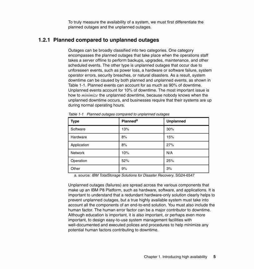
Outages can be broadly classified into two categories. One category encompasses the planned outages that take place when the operations staff takes a server offline to perform backups, upgrades, maintenance, and other scheduled events. The other type is unplanned outages that occur due to unforeseen events, such as power loss, a hardware or software failure, system operator errors, security breaches, or natural disasters. As a result, system downtime can be caused by both planned and unplanned events, as shown in Table 1-1. Planned events can account for as much as 90% of downtime. Unplanned events account for 10% of downtime. The most important issue is how to minimize the unplanned downtime, because nobody knows when the unplanned downtime occurs, and businesses require that their systems are up during normal operating hours.
Table 1-1 Planned outages compared to unplanned outages
Unplanned outages (failures) are spread across the various components that make up an IBM P8 Platform, such as hardware, software, and applications. It is important to understand that a redundant hardware-only solution clearly helps to prevent unplanned outages, but a true highly available system must take into account all the components of an end-to-end solution. You must also include the human factor. The human error factor can be a major contributor to downtime. Although education is important, it is also important, or perhaps even more important, to design easy-to-use system management facilities with well-documented and executed polices and procedures to help minimize any potential human factors contributing to downtime.
Type Planneda
a. source: IBM TotalStorage Solutions for Disaster Recovery, SG24-6547
Unplanned
Software 13% 30%
Hardware 8% 15%
Application 8% 27%
Network 10% N/A
Operation 52% 25%
Other 9% 3%
Chapter 1. Introducing high availability 5

1.2.2 Availability matrix
In an ideal environment, we strive for no unplanned outage, or 100% uptime. In reality, a 100% uptime system is expensive to implement. For certain applications, 99.9% uptime is adequate, leaving a downtime of only 1.4 minutes per day on average or 8.8 hours per year. See the following formula:
With 99.9% uptime, the total downtime= (100% - 99.9%) x 24 hours/day x 60 minutes/hour= 1.4 minutes per day on average OR= 1.4 minutes/day x 365 days = 8.8 hours per year
For certain applications, 99.99% or higher uptime is required. It is common to refer to 99%, 99.9%, 99.99%, and 99.999% as two nines, three nines, four nines, and five nines. The five nines uptime is generally thought of as the most achievable system with reasonable costs, leaving a downtime of less than a second per day on average or 5.26 minutes per year. See the following formula:
With 99.999% uptime, the total downtime= (100% - 99.999%) x 24 hours/day x 60 minutes/hour x 60 seconds/minute= 0.86 second (less than a second) per day on average OR= 0.86 second / 60 seconds/minute x 365 days = 5.26 minutes per year
Table 1-2 shows the relationship of availability in percentages and the actual downtime or time loss per year.
Table 1-2 Availability matrix
Note: The most important issue is minimizing the unplanned downtime, because nobody knows when the unplanned downtime occurs, and this downtime impacts business operations.
Availability in percentage Approximate time loss per year
99.9999% (six nines) 32 seconds
99.999% (five nines) 5 minutes
99.99% (four nines) 53 minutes
99.9% 8.8 hours
99% 87 hours (3.6 days)
90.0% 876 hours (36 days)
6 IBM High Availability Solution for IBM FileNet P8 Systems
1.2.3 Total availability of a system
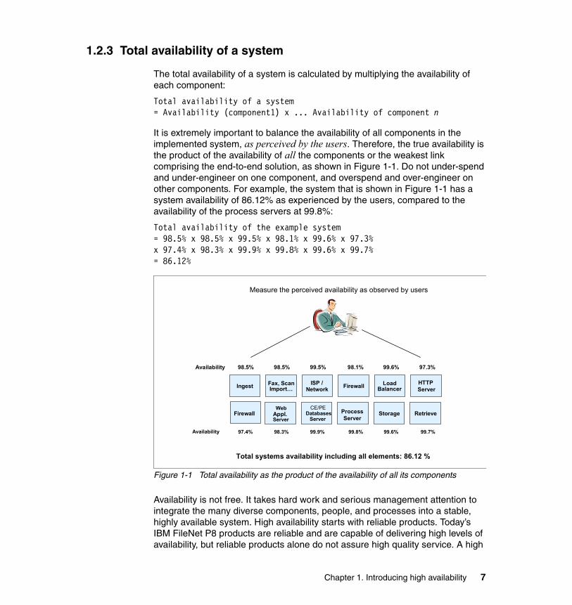
The total availability of a system is calculated by multiplying the availability of each component:
Total availability of a system= Availability (component1) x ... Availability of component n
It is extremely important to balance the availability of all components in the implemented system, as perceived by the users. Therefore, the true availability is the product of the availability of all the components or the weakest link comprising the end-to-end solution, as shown in Figure 1-1. Do not under-spend and under-engineer on one component, and overspend and over-engineer on other components. For example, the system that is shown in Figure 1-1 has a system availability of 86.12% as experienced by the users, compared to the availability of the process servers at 99.8%:
Total availability of the example system= 98.5% x 98.5% x 99.5% x 98.1% x 99.6% x 97.3% x 97.4% x 98.3% x 99.9% x 99.8% x 99.6% x 99.7%= 86.12%
Figure 1-1 Total availability as the product of the availability of all its components
Availability is not free. It takes hard work and serious management attention to integrate the many diverse components, people, and processes into a stable, highly available system. High availability starts with reliable products. Today’s IBM FileNet P8 products are reliable and are capable of delivering high levels of availability, but reliable products alone do not assure high quality service. A high
Measure the perceived availability as observed by users
Total systems availability including all elements: 86.12 %
Availability 98.5% 98.5% 99.5% 98.1% 99.6% 97.3%
Availability 97.4% 98.3% 99.9% 99.8% 99.6% 99.7%
Ingest Fax, ScanImport…
ISP / Network
Load BalancerFirewall HTTP
Server
FirewallWeb
Appl. Server
CE/PEDatabases
ServerProcessServer
Storage Retrieve
Chapter 1. Introducing high availability 7
level of availability relies on an infrastructure and application design that includes availability techniques and careful system integration. A lack of, or failure to follow, careful management and effective systems management procedures is one of the most common causes of an outage. Change management, in particular, requires more emphasis. Effective change and operational management practices that employ defined and repeatable processes contribute significantly to higher levels of availability. In the long run, these practices actually decrease the cost of IT services because of the resulting more effective and efficient use of IT resources.
1.3 Levels of availability
The high availability solutions require up-front planning with continual monitoring. Many areas have to be taken into consideration when designing and implementing a highly available solution. They include:
� Internet Protocol (IP) sprayer/load balancer� Firewall process� HTTP server� Web application server or mid-tier applications� Lightweight Directory Access Protocol (LDAP) server� Databases� Core processes, services, or engines� Disk subsystem� Operating system processes� Cluster or farm setups
Multiple technologies can be deployed to achieve high availability for systems. Figure 1-2 on page 9 shows availability levels and several of the commonly used technologies that are implemented to achieve each level.
8 IBM High Availability Solution for IBM FileNet P8 Systems
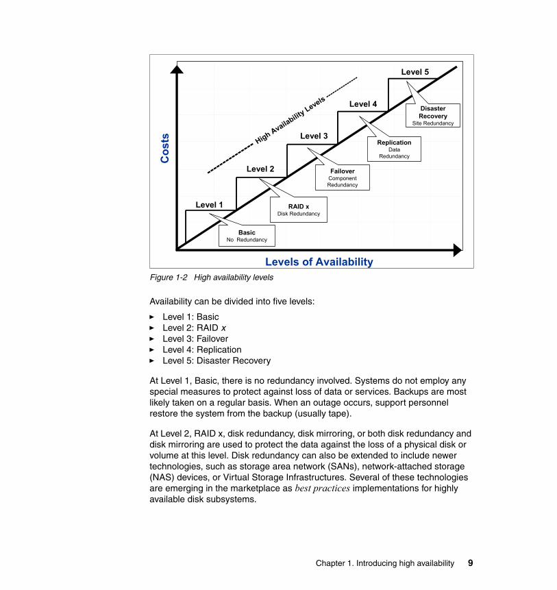
Figure 1-2 High availability levels
Availability can be divided into five levels:
� Level 1: Basic� Level 2: RAID x� Level 3: Failover� Level 4: Replication� Level 5: Disaster Recovery
At Level 1, Basic, there is no redundancy involved. Systems do not employ any special measures to protect against loss of data or services. Backups are most likely taken on a regular basis. When an outage occurs, support personnel restore the system from the backup (usually tape).
At Level 2, RAID x, disk redundancy, disk mirroring, or both disk redundancy and disk mirroring are used to protect the data against the loss of a physical disk or volume at this level. Disk redundancy can also be extended to include newer technologies, such as storage area network (SANs), network-attached storage (NAS) devices, or Virtual Storage Infrastructures. Several of these technologies are emerging in the marketplace as best practices implementations for highly available disk subsystems.
Cos
ts
Levels of Availability
BasicNo Redundancy
RAID xDisk Redundancy
Level 1
Level 2
Level 3
FailoverComponent Redundancy
ReplicationData
Redundancy
Disaster Recovery
Site Redundancy
Level 4
--------
-------
High Availability Levels ---
--------
----Level 5
Chapter 1. Introducing high availability 9
At Level 3, Failover, multiple instances or component redundancy are used to prevent a single-point-of-failure. In a system where multiple components are involved, an outage in any single component can result in service interruption to users. Multiple instances or redundancy for any single component need to be deployed for availability purposes. There are two primary techniques to deploy failover strategies:
� Application clustering, which is also known as farming (for example, WebSphere clustering)
� Platform clustering, for example, IBM PowerHA for AIX (HACMP - formerly IBM High Availability Cluster Multi-Processing)
Both of these methods are fundamental approaches to accomplishing high availability. Components that support application clustering can also take advantage of load balancing in addition to availability benefits. In order to achieve high availability in an IBM FileNet P8 Platform environment, you typically deploy both application clustering and platform clustering, assuming your solution is operating in a multi-tier and multi-server environment. If you run the full IBM FileNet P8 Platform stack on a single server (with all components in one machine), platform clustering or IP-based failover might be the appropriate strategy to deploy.
In a platform clustering environment, a standby or backup system is used to take over for the primary system if the primary system fails. In principle, almost any component can become highly available by employing platform clustering techniques. With IP-based cluster failover, we can configure the systems as active/active mutual takeover or active/standby (hot spare).
At Level 4, Replication or data redundancy, high availability implementation extends the protection by duplicating the database content (metadata and control tables) and file system content to another machine (server, NAS device, or SAN device) in the event of a hardware, software, disk, or data failure. This approach provides another level of protection and high availability in the event of a failure with data and content being replicated compared to a shared disk with failover strategy for Level 3. This type of a high availability implementation (replication) can also be used as a disaster recovery strategy; the difference is whether the servers are located within the same location or are geographically separated.
At Level 5, Disaster recovery, systems are maintained at separate sites. When the primary site becomes unavailable due to a disaster, the remote site (the backup site) becomes operational within a reasonable time to continue business operations. This level of high availability can be achieved through regular data backups in combination with geographical clustering, replication, or mirroring software. Disaster recovery is not addressed in this book.
10 IBM High Availability Solution for IBM FileNet P8 Systems

It is possible and a best practice to combine multiple high availability levels within a single solution. For example, you can have a failover (Level 3) strategy for hardware and a replication strategy (Level 4) for the database content and file system content with all servers using a disk redundancy strategy (Level 2).
IBM high availability solutions for IBM FileNet P8 use multiple strategies and technologies. The strategies and technologies that are used must be weighed against the costs for a particular implementation to meet the business requirements.
1.4 High availability cost compared to loss
Designing high availability solutions always requires you to balance the cost against the loss. Although highly available systems are desirable, an optimum balance between the costs of availability and the costs of unavailability is usually required. Factoring in the intangible consequences of an outage adds to the requirement to invest in extremely high levels of availability.
It is critical to understand the business impact of a failure and what the loss to the business is if an unplanned outage occurs. Too many times, we under design a solution that is too simple for a business and is not adequate to meet the business requirements, or we over design a solution that is too complex to manage and is not necessary for the business. Various businesses have differing costs for downtime. While a certain business might be less impacted when their systems are down, other businesses, such as financial services, might lose millions of dollars for each hour of downtime during business hours. The cost of downtime includes direct dollar losses and potentially reputation losses and bad customer relationships. Understanding the impact of downtime for your business helps you to define the level of high availability that you want to achieve for your business solution.
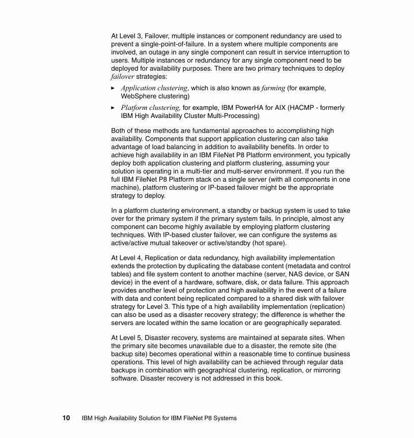
Figure 1-3 on page 12 shows how this balance applies to various operating environments and when the investment in availability can reach the point of diminishing returns. At a certain point, the cost of availability and the loss due to availability reaches an optimum availability investment point. The optimum point can be difficult to calculate with quantifying the losses being the more challenging of the two variables. The concept, though, is to try to reach an optimum balance by designing the most cost-effective, highly available solution
Note: The objective of designing and implementing a high availability solution is to provide an affordable level of availability that supports the business requirements and goals with acceptable system downtime.
Chapter 1. Introducing high availability 11
to support the business environment. As shown in Figure 1-3, high availability becomes increasingly expensive as you approach continuous availability (100%).
Figure 1-3 Cost of availability as opposed to loss due to availability
1.5 High availability and continuous availability
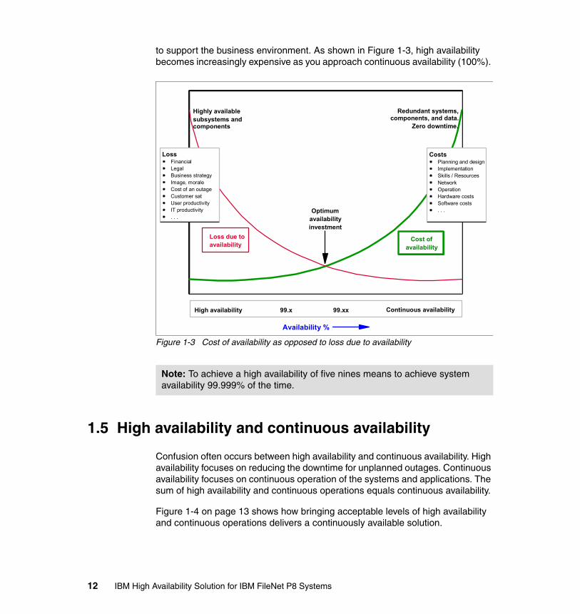
Confusion often occurs between high availability and continuous availability. High availability focuses on reducing the downtime for unplanned outages. Continuous availability focuses on continuous operation of the systems and applications. The sum of high availability and continuous operations equals continuous availability.
Figure 1-4 on page 13 shows how bringing acceptable levels of high availability and continuous operations delivers a continuously available solution.
Note: To achieve a high availability of five nines means to achieve system availability 99.999% of the time.
High availability
Loss due toavailability
Cost ofavailability
LossFinancialLegalBusiness strategyImage, moraleCost of an outageCustomer satUser productivityIT productivity. . .
CostsPlanning and designImplementationSkills / ResourcesNetworkOperationHardware costsSoftware costs. . .Optimum
availabilityinvestment
Highly availablesubsystems and components
Redundant systems, components, and data.
Zero downtime.
99.x Continuous availability99.xx
Availability %
12 IBM High Availability Solution for IBM FileNet P8 Systems
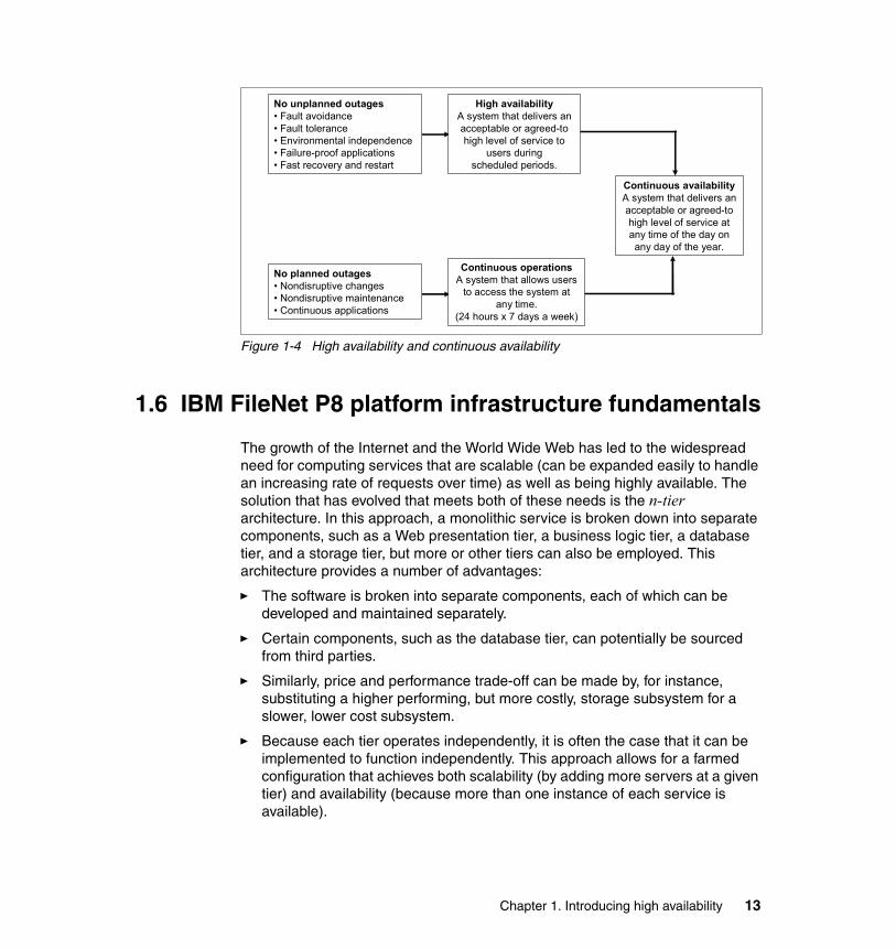
Figure 1-4 High availability and continuous availability
1.6 IBM FileNet P8 platform infrastructure fundamentals
The growth of the Internet and the World Wide Web has led to the widespread need for computing services that are scalable (can be expanded easily to handle an increasing rate of requests over time) as well as being highly available. The solution that has evolved that meets both of these needs is the n-tier architecture. In this approach, a monolithic service is broken down into separate components, such as a Web presentation tier, a business logic tier, a database tier, and a storage tier, but more or other tiers can also be employed. This architecture provides a number of advantages:
� The software is broken into separate components, each of which can be developed and maintained separately.
� Certain components, such as the database tier, can potentially be sourced from third parties.
� Similarly, price and performance trade-off can be made by, for instance, substituting a higher performing, but more costly, storage subsystem for a slower, lower cost subsystem.
� Because each tier operates independently, it is often the case that it can be implemented to function independently. This approach allows for a farmed configuration that achieves both scalability (by adding more servers at a given tier) and availability (because more than one instance of each service is available).
Continuous availabilityA system that delivers an acceptable or agreed-to high level of service at any time of the day on any day of the year.
No unplanned outages• Fault avoidance• Fault tolerance• Environmental independence• Failure-proof applications• Fast recovery and restart
No planned outages• Nondisruptive changes• Nondisruptive maintenance• Continuous applications
High availabilityA system that delivers an acceptable or agreed-to high level of service to
users during scheduled periods.
Continuous operationsA system that allows users
to access the system at any time.
(24 hours x 7 days a week)
Chapter 1. Introducing high availability 13
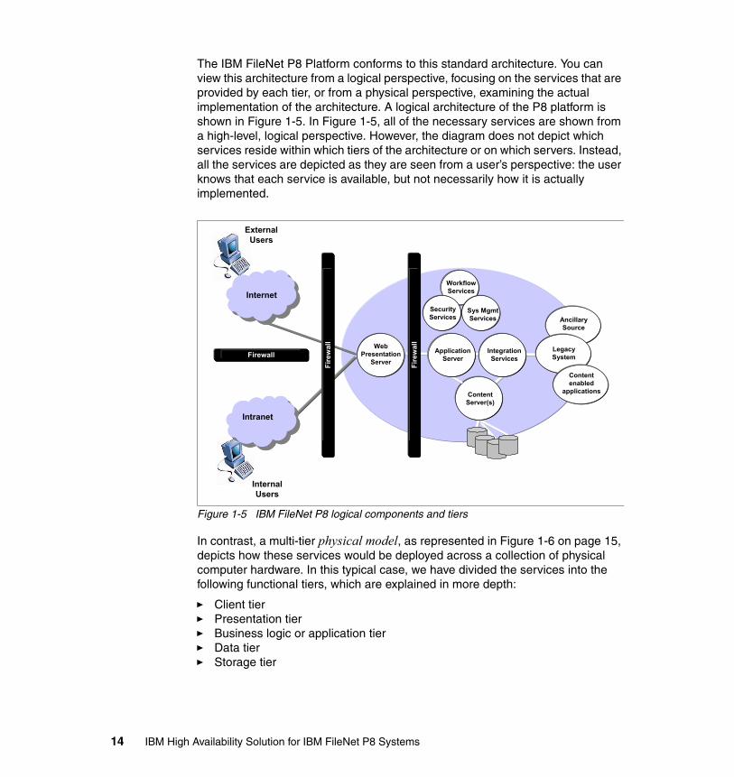
The IBM FileNet P8 Platform conforms to this standard architecture. You can view this architecture from a logical perspective, focusing on the services that are provided by each tier, or from a physical perspective, examining the actual implementation of the architecture. A logical architecture of the P8 platform is shown in Figure 1-5. In Figure 1-5, all of the necessary services are shown from a high-level, logical perspective. However, the diagram does not depict which services reside within which tiers of the architecture or on which servers. Instead, all the services are depicted as they are seen from a user’s perspective: the user knows that each service is available, but not necessarily how it is actually implemented.
Figure 1-5 IBM FileNet P8 logical components and tiers
In contrast, a multi-tier physical model, as represented in Figure 1-6 on page 15, depicts how these services would be deployed across a collection of physical computer hardware. In this typical case, we have divided the services into the following functional tiers, which are explained in more depth:
� Client tier � Presentation tier� Business logic or application tier� Data tier� Storage tier
Ancillary Source
Web Presentation
ServerFire
wal
lFi
rew
all
Fire
wal
lFi
rew
all
Content Server(s)
FirewallFirewall Integration Services
IntranetIntranet
InternetInternet
InternalUsers
ExternalUsers
Application Server
Workflow Services
Security Services
Sys Mgmt Services
Legacy System
Content enabled
applications
14 IBM High Availability Solution for IBM FileNet P8 Systems
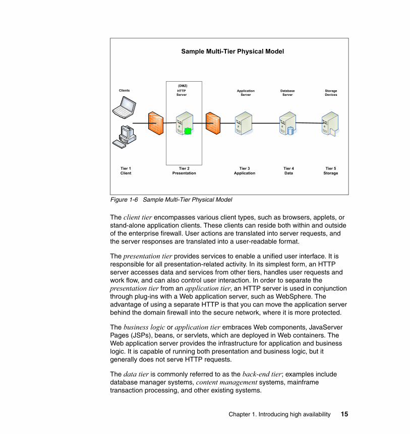
Figure 1-6 Sample Multi-Tier Physical Model
The client tier encompasses various client types, such as browsers, applets, or stand-alone application clients. These clients can reside both within and outside of the enterprise firewall. User actions are translated into server requests, and the server responses are translated into a user-readable format.
The presentation tier provides services to enable a unified user interface. It is responsible for all presentation-related activity. In its simplest form, an HTTP server accesses data and services from other tiers, handles user requests and work flow, and can also control user interaction. In order to separate the presentation tier from an application tier, an HTTP server is used in conjunction through plug-ins with a Web application server, such as WebSphere. The advantage of using a separate HTTP is that you can move the application server behind the domain firewall into the secure network, where it is more protected.
The business logic or application tier embraces Web components, JavaServer Pages (JSPs), beans, or servlets, which are deployed in Web containers. The Web application server provides the infrastructure for application and business logic. It is capable of running both presentation and business logic, but it generally does not serve HTTP requests.
The data tier is commonly referred to as the back-end tier; examples include database manager systems, content management systems, mainframe transaction processing, and other existing systems.
Tier 1Client
Tier 2Presentation
Tier 3Application
Tier 4Data
Sample Multi-Tier Physical Model
Tier 5Storage
(DMZ)Clients Application
ServerHTTP Server
DatabaseServer
Storage Devices
Chapter 1. Introducing high availability 15
In a highly available IBM FileNet P8 solution, there are several components within the tiers that have to be taken into consideration when designing an end-to-end high availability system:
� Client workstations
� The Domain Name System (DNS) server
� IP sprayers/load balancers
� Firewall process
� HTTP servers
� Web application server and mid-tier applications (such as Workplace/WorkplaceXT)
� IBM FileNet P8 applications
� Databases
� Disk subsystems
� LDAP servers
Redundancy of these components can be accomplished through either application clustering, platform clustering, or a combination of both application clustering and platform clustering.
1.6.1 Application clustering (server farms)
A server farm is a group of identical servers, which are accessible through hardware or software load balancing technology. All the servers are actively providing the same set of services and are interchangeable. A load balancer distributes incoming client requests over the servers in the group. For example, there are hardware-based load balancers that automatically spread the incoming client workload across a farm of servers, each providing access to the same content or services. Also available are the software-based load balancing capabilities that are built into products, such as WebSphere Network Deployment Edition. As requests come in from external clients, the software-based load balancer spreads out the requests across the servers to balance the workload evenly. Both software and hardware load balancers offer various algorithms that can be set up to spread requests among multiple servers in a farm.
A load-balanced server farm provides both better availability and better scalability than a single server. When a server fails, the load balancer automatically detects the failure and redirects user requests to another server in the farm, thereby keeping the site available. Administrators can increase system performance and capacity by adding servers to the farm.
16 IBM High Availability Solution for IBM FileNet P8 Systems
With a hardware-based load balancing solution, redundant load balancers are required to avoid a single point of failure. The software-based load balancers are typically designed to avoid a single point of failure by running the network load balancing software on each server in the farm. There are many competing load balancing products that can be considered to find the best combination of price and performance.
Server farms are best suited to server tiers that are processing-centric rather than data-centric, because all the servers in the farm are clones of each other. Processing logic does not change often, so it is feasible to keep all the servers identical in a processing-centric tier. Web servers and application servers that execute business logic are both good candidates for server farms.
Data-centric tiers, such as file servers and data servers, are not well suited for farming, because their data content constantly changes. Keeping this dynamic data identical across a group of cloned file or data servers, and managing the client accesses to the data to protect the integrity of the data in the face of multiple writers, can be difficult in a farm, with a copy of data and file on each server. The better solution for this type of server is the platform clustering.
1.6.2 Platform clustering (server clusters)
Platform clustering, which is sometimes referred to as server clusters, is based on the concept of shared software configuration data storage. The servers have a shared disk that holds the configuration data that is shared between both nodes. In contrast, server farms do not share software configuration data among the servers in the farm. Each server has its own copy of the configurations that it has to run, and in most cases, the configuration is an exact copy of the files that are on the other servers in the farm.
Many server hardware and software vendors offer vendor-specific server clustering products as their high availability offering for these kinds of data-centric servers. These products all have the following general characteristics:
� Two or more servers share a highly available disk array for data storage. The array incorporates redundant copies of the data, but it appears as a single disk resource to the servers, therefore, avoiding the need for data replication between servers. Each server has its own local disk for the static storage of the operating system, utilities, and other software.
� A common set of applications runs on each server.
� Server clients see the cluster as a single virtual server.
� If the active server fails, the other server picks up the workload of the failed server (sometimes referred to as a failover). When the failed server is
Chapter 1. Introducing high availability 17
repaired and is brought back online, the workload is shifted back from the other server to the originally active server (sometimes referred to as a failback). In certain configurations, the repaired server simply becomes the new backup server, and no failback is required.
� The failover feature can mask both planned and unplanned outages from users. For instance, an intentional failover can be done to allow one of the servers to be backed up and then brought back online in a failback.
� In most server clusters, only one server is actively serving clients at a time, which is called an active-passive configuration. Certain cluster server products also support another mode, which is called an active-active configuration. In this mode, all the servers in the cluster can be actively sharing part of the workload at the same time. It typically requires an application that is designed to partition data sets among the servers to avoid data integrity problems resulting from concurrent updates to the same data from multiple servers.
IBM offers IBM PowerHA™ for AIX (HACMP - formerly IBM High Availability Cluster Multi-Processing), as the server cluster product for the AIX environment.
Server clusters typically communicate through a broadcast, or they share a central repository to keep track of cluster information and cluster node status. Each machine in the cluster is referred to as a node. Each node in the cluster monitors the local services that it is running and broadcasts this information on a private network connection. This private network connection allows all nodes in the cluster to know the status of all clustered resources. In the event that a service on one node fails, another node receives this status through the private network connection and in response, can start the service locally to maintain high availability for the service.
1.6.3 Choosing between a farm or a cluster
The technology direction for the IBM FileNet P8 Platform and its products is to support load-balanced server farms wherever possible, in preference to active-passive server clusters.
Load-balanced server farms have a scalability advantage, exhibit better server utilization, and recover more quickly from server failures when compared to active-passive server clusters. Farming support is continually being added to the IBM FileNet P8 Platform and products that previously only supported active-passive server clusters. See Chapter 3, “High availability strategies for IBM FileNet P8 systems” on page 43 for a further description of each component in the IBM FileNet P8 Platform and the type of clustering configuration that it supports.
18 IBM High Availability Solution for IBM FileNet P8 Systems
Chapter 2. IBM FileNet P8 system architectural overview
In this chapter, we provide an overview of the overall IBM FileNet P8 Platform system architecture and its three core components: Content Engine, Process Engine, and Application Engine. In addition, we describe two other important server components: Image Services (IS) and the Content Search Engine (CSE). We discuss the services that these engines provide and the communication protocols that are employed for communication between the various components.
We describe the following topics:
� Architectural overview� Content Engine� Process Engine� Application Engine� Image Services and CFS-IS� Content Search Engine
2
© Copyright IBM Corp. 2009. All rights reserved. 19

2.1 Architectural overview
The IBM FileNet P8 suite of products provides a business-centric Enterprise Content Management (ECM) system. The core components of the IBM FileNet P8 suite of products are Content Engine (CE), Process Engine (PE), and Application Engine (AE). Content Engine stores documents, workflow objects, and custom objects. Process Engine manages business processes, also known as workflows or workflow processes. Application Engine is the ready to use, predefined user interface for the IBM FileNet P8 Platform, which through its layered application, Workplace or WorkplaceXT, provides a general folder-based view of an IBM FileNet P8 content repository. The user interface also provides various Process Engine components for representing objects, such as inboxes, public queues, and step processors.
Together, these core engines provide the IBM FileNet P8 Platform on which many applications are built, including:
� IBM FileNet Content Manager
� IBM FileNet Business Process Manager (BPM)
� Process Analyzer (a tool that is provided with BPM)
� Process Simulator (a tool that is provided with BPM)
� IBM FileNet Capture
� IBM FileNet Email Management (currently replaced by IBM Content Collection for Emails)
� IBM FileNet Records Crawler (currently replaced by IBM Content Collection for File Systems)
� IBM FileNet Records Manager
� IBM FileNet Business Activity Monitoring (BAM)
� IBM FileNet eForms
� IBM FileNet Business Process Framework (BPF)
� Rendition Engine
� Client-developed applications
Content Engine and Process Engine are servers. They can be accessed by client programs, including the Application Engine user interface, but also by stand-alone programs that can be developed by clients or third parties. The CE and PE both provide Application Programming Interfaces (APIs) for accessing all of their features and capabilities. Client programs of these servers are often Java™ programs, so they both offer Java APIs. The Java APIs allow stand-alone or Java 2 Platform, Enterprise Edition (J2EE™)-based applications written in
20 IBM High Availability Solution for IBM FileNet P8 Systems
Java to access all the features of Content Engine and Process Engine. Most of the products that are listed access Content Engine or Process Engine using their Java APIs, which is usually the most efficient method to access the engines.
2.2 Content Engine
In an enterprise content management environment, the content of each document is stored and managed by content management software. In the case of the IBM FileNet P8 suite of products, this function is performed by the Content Engine (CE) server. It is implemented as a J2EE application, and so it runs within a J2EE application server. Content Engine supports WebSphere, WebLogic, and JBoss® application servers.
The properties associated with each document comprise the document’s metadata. Typical metadata properties include: creator of the document, creation time of the document, and the type of the document. The metadata is stored in a database that is known as the document catalog. Content Engine supports DB2, Oracle, and SQL Server® databases. Searching for a particular document consists of querying the Content Engine database, and then retrieving the content corresponding to the matching documents. More than one piece of content, which is called a content element, can be associated with a single document. The content elements can be stored in any of the following locations:
� Database� Conventional file system� Fixed-content device
Although content can be stored in the Content Engine database, customers typically do not use this configuration, because the database can become too large and therefore difficult to manage if it holds all the content. Most customers therefore use one of the other two choices to store content: the file system or a fixed content device. If a file system is used, it is most often stored on a network-attached storage (NAS) or storage-attached network (SAN) device. Implementing a Redundant Array of Independent Disks (RAID) system provides both higher performance and high availability of the data.
Fixed content devices typically include specialized storage subsystems that meet certain compliance requirements, such as the ability to guarantee that content is never modified and that it cannot be deleted until a specified date in the future. These devices are often used to store legal and other documents in the financial, insurance, and related industries.
The architecture of Content Engine allows for a variety of different devices to be used as fixed content devices. Content Engine can also be connected to other
Chapter 2. IBM FileNet P8 system architectural overview 21

content storage systems, using these systems to store the content as conventional fixed content devices do. Content Federated Services (CFS) allows Content Engine to import document metadata and populate its object store while leaving the actual content in the remote content management system. This process, called federation, provides a number of unique benefits:
� New applications, taking advantage of the rich metadata object model provided by Content Engine, can be developed and used with both new content that is stored natively inside Content Engine and with older content that resides in an existing content management system.
� Because the content remains inside the existing system, applications that use interfaces that are provided by that system can continue to be used.
� The time and space required to federate the metadata of existing documents is much less than the time and space required for a full migration of content from the old system to the new one. No downtime is required of either system. Users can continue to use and add new documents to the existing system during the federation process.
� Clients can continue to use the existing systems and related hardware for as long as desired. Conversely, a migration over time can be effected, first by quickly federating the metadata, and then slowly moving content from the existing system into Content Engine as time and storage space permit. When the content of the last documents in the existing system have been moved, then the existing system can be retired.
A single Content Engine domain can manage one or more content repositories, which are called object stores. Each object store consists of a metadata database and one or more content storage locations. Information about object stores and domain configuration information are kept in a database called Global Configuration Data (GCD). By sharing access to the GCD, multiple Content Engines can participate in a single Content Engine domain, allowing these Content Engines to access the same object stores. This feature is the key for both Content Engine’s scalability (more servers can be added as demand grows) and its high availability (if one node fails, the other nodes can still be used to continue processing requests until the failed node can be restored).
Content Engine supports user-extensible document classes, allowing users to define new types of documents that can be stored and what additional metadata these classes of documents will maintain. The CE also supports event processing, that is, the ability to perform a user-defined action whenever a chosen event happens, such as creating, deleting, checking in, and checking out documents. Security can be configured on document classes or on an individual document using an Access Control List (ACL), allowing the owner of a document to define precisely who can access or modify the document. Content can be versioned, that is, revisions to the content of the document can be checked into
22 IBM High Availability Solution for IBM FileNet P8 Systems
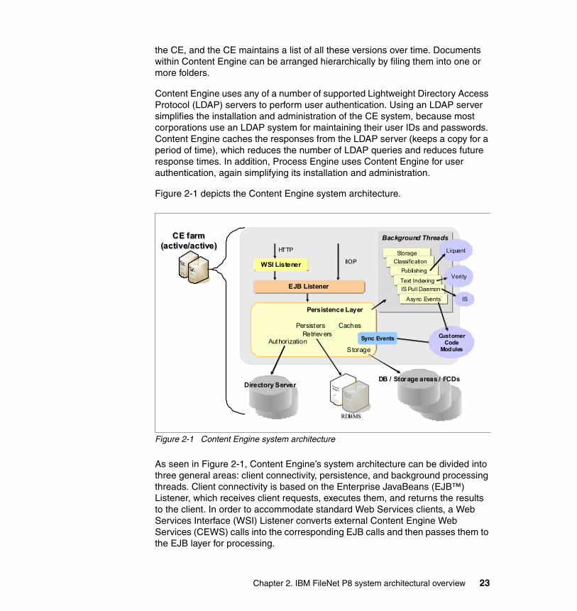
the CE, and the CE maintains a list of all these versions over time. Documents within Content Engine can be arranged hierarchically by filing them into one or more folders.
Content Engine uses any of a number of supported Lightweight Directory Access Protocol (LDAP) servers to perform user authentication. Using an LDAP server simplifies the installation and administration of the CE system, because most corporations use an LDAP system for maintaining their user IDs and passwords. Content Engine caches the responses from the LDAP server (keeps a copy for a period of time), which reduces the number of LDAP queries and reduces future response times. In addition, Process Engine uses Content Engine for user authentication, again simplifying its installation and administration.
Figure 2-1 depicts the Content Engine system architecture.
Figure 2-1 Content Engine system architecture
As seen in Figure 2-1, Content Engine’s system architecture can be divided into three general areas: client connectivity, persistence, and background processing threads. Client connectivity is based on the Enterprise JavaBeans (EJB™) Listener, which receives client requests, executes them, and returns the results to the client. In order to accommodate standard Web Services clients, a Web Services Interface (WSI) Listener converts external Content Engine Web Services (CEWS) calls into the corresponding EJB calls and then passes them to the EJB layer for processing.
RDBMSRDBMS
CE farm(active/active)
CE farm(active/active)
Background ThreadsBackground Threads
Directory Server
Customer Code
Modules
IIOPIIOP
HTTPHTTP
DB / Storage areas / FCDs
Verity
Liquent
IS
WSI ListenerWSI Listener
EJB ListenerEJB Listener
Persistence Layer
Persisters Caches Retrievers
AuthorizationStorage
Persistence Layer
Persisters Caches Retrievers
AuthorizationStorage
Sync Events
StorageStorageClassificationClassification
PublishingPublishing
Text IndexingText Indexing
IS Pull DaemonIS Pull Daemon
Async EventsAsync Events
Chapter 2. IBM FileNet P8 system architectural overview 23
The Persistence Layer is responsible for many of the Content Engine’s basic functions. It handles communications with the supported databases and storage and retrieval of content from storage areas, including the database, FileStore Areas, and Fixed Content Devices (FCDs). The Persistence Layer also performs authorization for the Content Engine by communicating with the supported LDAP server, and this layer also manages Content Cache Areas and their use. Finally, the Persistence Layer initiates event processing in response to changes to content and metadata, such as document creation, updates, and deletions.
For Synchronous Events, the corresponding event code is executed directly by the Persistence Layer. In other cases, the Persistence Layer will signal a background thread about an action of interest, and the Content Engine will perform further processing asynchronously. Asynchronous processing means that the activity occurs within a separate transaction and that the server does not wait until the operation has completed before returning control to the client. Such processing not only includes explicit Asynchronous Events, which can be used for workflow launches to request processing by the Process Engine, but it also includes activities, such as:
� Classification: Content Engine provides a framework for automatically assigning incoming documents to a designated document class. With automatic document classification, you can automatically change a document’s class and set its property values. Content Engine provides ready to use, predefined support for the auto-classification of documents.
� Publishing: Content Engine’s publishing framework provides a rich set of tools and capabilities for re-purposing the content that is contained in document objects into HTML and PDF formats. Publishing is useful when you want to make a document available to customers, but you do not want them to be able to modify the document. When you publish a document, you maintain control over the source document and can continue to update and make changes to the source that are not visible to users of the publication document. When you are ready to make the new version of the document available to your users, you republish the source document, thereby creating a new version of the publication document. Document Publishing is performed by the Rendition Engine.
� Indexing: Indexing a document consists of breaking the document into individual words and storing those words into a separate database, which is called a Collection, so that users can search for documents based on their content. This process is called Content Based Retrieval (CBR) or full text indexing.
Other background threads within the Content Engine include the IS Pull Daemon, which is responsible for communicating with an Image Services server to perform Content Federated Services for Image Services (CFS-IS), and storage
24 IBM High Availability Solution for IBM FileNet P8 Systems
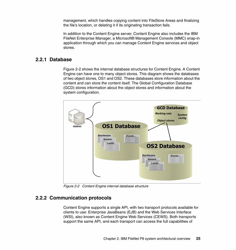
management, which handles copying content into FileStore Areas and finalizing the file’s location, or deleting it if its originating transaction fails.
In addition to the Content Engine server, Content Engine also includes the IBM FileNet Enterprise Manager, a Microsoft® Management Console (MMC) snap-in application through which you can manage Content Engine services and object stores.
2.2.1 Database
Figure 2-2 shows the internal database structures for Content Engine. A Content Engine can have one to many object stores. This diagram shows the databases of two object stores, OS1 and OS2. These databases store information about the content and can store the content itself. The Global Configuration Database (GCD) stores information about the object stores and information about the system configuration.
Figure 2-2 Content Engine internal database structure
2.2.2 Communication protocols
Content Engine supports a single API, with two transport protocols available for clients to use: Enterprise JavaBeans (EJB) and the Web Services Interface (WSI), also known as Content Engine Web Services (CEWS). Both transports support the same API, and each transport can access the full capabilities of
RDBMSRDBMS OS1 Database
GCD DatabaseMarking sets
Object stores
System config
DocVersionGeneric
ListOf…
Events…
OS2 DatabaseDocVersion
Generic
ListOf…
Events…
Chapter 2. IBM FileNet P8 system architectural overview 25
Content Engine. These transports are sometimes referred to as the EJB API and the Web Services API of Content Engine. In reality, both transports offer the same set of services and thus represent the same API in separate ways.
The EJB transport resolves to a protocol that is specific to each application server. Therefore, clients of the Java API running within a J2EE application server and using the EJB transport must be running on the same application server as Content Engine (for instance, IBM WebSphere Application Server) so that the client and server portions of the EJB transport are compatible. Stand-alone Java applications that are to be Content Engine clients must similarly be linked with client libraries supplied with the application server on which Content Engine is running.
The Content Java API allows either transport to be used by Java clients. The EJB transport generally provides faster performance than the WSI transport, because internally within Content Engine, the WSI layer is built on top of the EJB layer. For this reason, most IBM FileNet P8 products that are written in Java and work with Content Engine, such as the Application Engine, use the Java API with the EJB transport. However, the WSI transport offers several advantages:
� Client applications can be written in any language, not just Java, because the Web Services Interface and transport are standards.
� No application-server-specific libraries are required by the clients, and access through firewalls can be simpler, easing deployment.
� The availability of the Web Services Interface allows Content Engine to participate fully in standard service-oriented architectures (SOAs).
Content Engine also provides a .NET API. This API uses the WSI transport to communicate with the server. Similarly, there is a COM API provided for backward compatibility with earlier versions of Content Engine. This API also uses the WSI transport for server communications.
2.3 Process Engine
Process Engine is a 32-bit C++ application that follows a single-threaded multi-process model. Process Engine currently runs on IBM AIX operating system, Hewlett-Packard UNIX (HP-UX) operating system, Sun™ Microsystem Solaris operating environment, and Microsoft Windows® operating system. Process Engine provides enterprise-level software services for managing all aspects of business processes, including process modeling, routing, execution, process simulation, and analysis. Process Engine allows you to create, modify, and manage processes implemented by applications, enterprise users, or external users (such as partners and customers).
26 IBM High Availability Solution for IBM FileNet P8 Systems
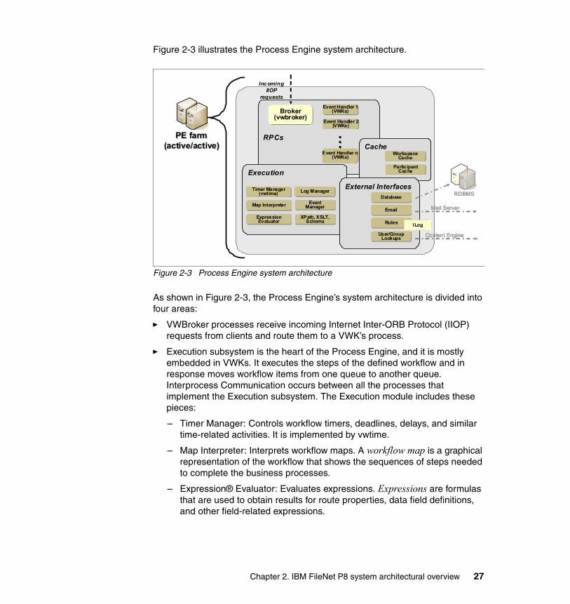
Figure 2-3 illustrates the Process Engine system architecture.
Figure 2-3 Process Engine system architecture
As shown in Figure 2-3, the Process Engine’s system architecture is divided into four areas:
� VWBroker processes receive incoming Internet Inter-ORB Protocol (IIOP) requests from clients and route them to a VWK’s process.
� Execution subsystem is the heart of the Process Engine, and it is mostly embedded in VWKs. It executes the steps of the defined workflow and in response moves workflow items from one queue to another queue. Interprocess Communication occurs between all the processes that implement the Execution subsystem. The Execution module includes these pieces:
– Timer Manager: Controls workflow timers, deadlines, delays, and similar time-related activities. It is implemented by vwtime.
– Map Interpreter: Interprets workflow maps. A workflow map is a graphical representation of the workflow that shows the sequences of steps needed to complete the business processes.
– Expression® Evaluator: Evaluates expressions. Expressions are formulas that are used to obtain results for route properties, data field definitions, and other field-related expressions.
RPCs
Execution
PE farm(active/active)
PE farm(active/active)
Broker (vwbroker)
Broker (vwbroker)
Content EngineContent Engine
Incoming IIOP
requests
Event Handler 1(VWKs)
Event Handler 1(VWKs)
Event Handler 2(VWKs)
Event Handler 2(VWKs)
Event Handler n(VWKs)
Event Handler n(VWKs)
…
Cache
Log ManagerLog Manager
Workspace Cache
Workspace Cache
Participant Cache
Participant Cache
Timer Manager (vwtime)
Timer Manager (vwtime)
Map InterpreterMap Interpreter
Expression Evaluator
Expression Evaluator
Event Manager
Event Manager
External InterfacesDatabaseDatabase
EmailEmail
RulesRules
User/Group Lookups
User/Group Lookups
Mail ServerMail Server
XPath, XSLT, Schema
XPath, XSLT, Schema
RDBMSRDBMS
ILog
Chapter 2. IBM FileNet P8 system architectural overview 27

– Log Manager: Manages logs. Event logs contain a record of specific system-related or workflow-related events for each isolated region. This type of logging is useful for tracking and analyzing workflow activity.
– Event Manager: Workflows within Process Engine can involve waiting for an event to occur, after which the workflow can proceed. This processing is handled by the Event Manager.
– XPath/Extensible Stylesheet Language Transformation (XSLT) processing: Processes XPath and XSLT. It includes functions for manipulating XML formatted strings.
� Cache: For performance reasons, Process Engine caches commonly used information. In particular, the users and groups that are returned by the directory service are cached in the Participant Cache. Another cache is Workspace Cache (a workspace is the configuration components of a type of workflow instance).
� External Interfaces of the PE include its database connections, the ability to originate Simple Mail Transfer Protocol (SMTP) e-mail, the authentication of users and groups through the Content Engine, and its interface for rules processing.
As with Content Engine, each Process Engine can operate independently of any others, storing all necessary data in the database. By load balancing requests across a group of PE servers, clients can achieve both scalability and high availability with Process Engine.
2.3.1 Component Integrator
Component Integrator provides a framework that enables Process Engine to connect to external applications or services. With Component Integrator, you can make custom Java code or existing Java Message Service (JMS) components available in a workflow. A component, in this context, can be a Java object or a JMS messaging system. Component Integrator handles the import of Java classes and manages the communication between Process Engine and the external interfaces. Component Integrator provides the Web Services invocation framework for process orchestration, which uses SOAP/HTTP as its transport protocol. Component Integrator includes adaptors that communicate events from Process Engine to external system, services, or entities. Adaptors interact with various types of components from a workflow process step. Each of these interfaces is managed in Application Engine by an instance of Component Manager.
Component Integrator provides a default set of Content Engine operations in Process Engine. It can also include any custom components that are created by you or other people. Instances of Component Manager manage connections to
28 IBM High Availability Solution for IBM FileNet P8 Systems

external components. In a consistent way, Content Engine operations allow a workflow step to perform operations on Content Engine, such as filing a document in a folder or setting the properties of a document.
2.3.2 Communication protocols
Similar to Content Engine, Process Engine offers its services through two transports: Web Services and CORBA/IIOP. The Process Java API uses the IIOP transport, so clients, such as Application Engine, use this transport to connect to Process Engine. The Web Services interface can be used by clients in many languages, including IBM FileNet P8 applications, such as the SharePoint® Connector.
Process Engine acts as a client of Content Engine. In response to Content Engine requests, Process Engine executes workflow operations. It also uses Content Engine to authenticate IBM FileNet P8 domain users. The connections are made using Content Engine’s Web Services transport.
Process Engine can be either a provider or a consumer of Web services by using the process orchestration framework. Process orchestration uses standard Web Services definitions for business process management systems, such as Business Process Execution Language (BPEL), that were created to allow an IBM FileNet Business Process Manager system to participate in an SOA. Process orchestration also uses the Web Services transport.
2.4 Application Engine
Application Engine forms the Web tier front end, or presentation layer, to Content Engine and Process Engine. Application Engine is the IBM FileNet P8 Platform component that hosts the Workplace or WorkplaceXT1 Web application, Workplace Java applets, application development tools, and other IBM FileNet P8 Web applications.
Workplace or WorkplaceXT forms the presentation layer (a Web-based user interface) for both Content Engine and Process Engine. When a user logs in, the credentials that are supplied are maintained and protected by Application Engine. If Secure Sockets Layer (SSL) security is in use, Application Engine also provides this function. Workplace or WorkplaceXT runs in a Web container in a J2EE application server, such as IBM WebSphere Application Server, as used in the configuration for this book. Component Manager, another Java application residing in Application Engine, manages interaction with external entities (in this
1 WorkplaceXT is the new application name, replacing the previous version that is called Workplace.
Chapter 2. IBM FileNet P8 system architectural overview 29

context, components). Workplace can provide custom actions by integrating external custom code. Workplace also has the ability to configure custom viewers based on document Multipurpose Internet Mail Extensions (MIME) types.
In addition to the Workplace application, Application Engine can host a number of other features and applications:
� Records Manager is an addition to the features of Workplace that provides records management-related functions. These functions include declaring records, setting retention periods, and performing record holds on documents that must not be deleted because of pending litigation or other reasons.
� eForms is an electronic forms management package.
� Integration with Microsoft Office enables users to manage Office documents and Outlook® e-mail messages within the IBM FileNet P8 content repository. Users can store, search, and retrieve documents, e-mail, and attachments directly from Microsoft Office menus. In addition to securing and versioning Office documents, users can browse object stores and insert properties into Word and Excel® documents. Users can also use entry templates to add documents to an object store and launch an approval workflow.
� WebDAV Servlet allows users to create and edit documents and manage content from WebDAV-compliant applications, such as Microsoft Word.
� Component Integrator provides a framework that allows you to create connectors to external applications, services, or entities. See 2.3.1, “Component Integrator” on page 28 for details.
In addition to the these features, Application Engine includes the Java APIs for Content Engine and Process Engine, the .NET API for Content Engine, and the Web Application Toolkit (WAT). The Web Application Toolkit is the basis of Application Engine and Records Manager. It provides an extensible framework and reusable modules for building Web applications. The Toolkit provides application developers with access to Content Engine, Process Engine, and third-party back-end servers. It supplies the behaviors and data structures for authentication, event routing, state information, preferences, localization, and other features of robust and scalable applications. The Toolkit’s reusable user interface component model facilitates the development of a robust HTML-based application user interface with little or no DHTML/JavaScript required. In addition to the toolkit, Application Engine also includes the Application Integration Toolkit and the Application Integration Express Add-in. For more information about these services and applications, refer to IBM FileNet P8 System Overview, GC31-5482.
Figure 2-4 on page 31 shows the Application Engine system architecture.
30 IBM High Availability Solution for IBM FileNet P8 Systems
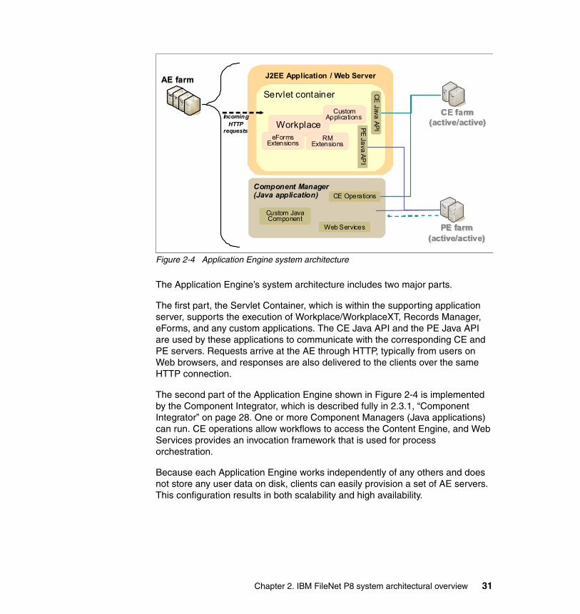
Figure 2-4 Application Engine system architecture
The Application Engine’s system architecture includes two major parts.
The first part, the Servlet Container, which is within the supporting application server, supports the execution of Workplace/WorkplaceXT, Records Manager, eForms, and any custom applications. The CE Java API and the PE Java API are used by these applications to communicate with the corresponding CE and PE servers. Requests arrive at the AE through HTTP, typically from users on Web browsers, and responses are also delivered to the clients over the same HTTP connection.
The second part of the Application Engine shown in Figure 2-4 is implemented by the Component Integrator, which is described fully in 2.3.1, “Component Integrator” on page 28. One or more Component Managers (Java applications) can run. CE operations allow workflows to access the Content Engine, and Web Services provides an invocation framework that is used for process orchestration.
Because each Application Engine works independently of any others and does not store any user data on disk, clients can easily provision a set of AE servers. This configuration results in both scalability and high availability.
AE farmAE farm J2EE Application / Web Server
Servlet container
Component Manager (Java application)
WorkplaceCustom
Applications
PE farm(active/active)
PE farm(active/active)
PE Java API
CE Operations
Custom Java Component
Web Services
CE farm(active/active)
CE farm(active/active)
CE Java API
eFormsExtensions
RM Extensions
Incoming HTTP
requests
Chapter 2. IBM FileNet P8 system architectural overview 31
2.4.1 Communication protocols
Clients of Application Engine are Web browsers. They use the HTTP or HTTPS protocols in connecting to Application Engine. As a client of Content Engine and Process Engine, Application Engine uses their client protocols to connect to them. For Content Engine, the communication protocol used is the EJB transport. For Process Engine, the protocol is IIOP. Both protocols are carried over TCP/IP connections.
2.5 Image Services and CFS-IS
Image Services (IS) is a powerful image and document management system. It integrates with a number of storage devices, including optical disk systems, Magnetic Storage and Retrieval (MSAR), and specialty storage units for compliance, such as IBM System Storage™ DR550 and IBM System Storage N series storage.
Many companies with Image Services implementations want to take advantage of the functionality and features in the IBM FileNet P8 suite, including Content Engine’s document class data model and Process Engine’s process workflow capabilities. Without having to give up existing applications and procedures that work with Image Services, IBM FileNet P8 offers Content Federation Services for Image Services (CFS-IS) for these companies.
Content Federation Services (CFS) allows Content Engine to function as the master metadata catalog for documents that are stored in IBM FileNet P8, Image Services, and other disparate content sources. Documents can be searched and retrieved directly by any IBM FileNet P8 application, no matter where the actual content is stored.
For Image Services, CFS-IS federates the Image Services documents to the IBM FileNet P8 catalog, meaning that the Image Services document metadata is stored in the IBM FileNet P8 catalog, while the content remains where it was stored originally, until a user retrieves the document.
CFS-IS allows the Image Services users to deploy new IBM FileNet P8 applications, which can use the documents that are stored in Image Services, while the existing Image Services applications can continue to function for as long as they are required, until the decision is made to replace them with IBM FileNet P8 applications.
CFS-IS also enables Content Engine to use Image Services as a content storage device. Users of IBM FileNet P8 applications can have full access to content that is stored in existing Image Services repositories. Anything that is created in
32 IBM High Availability Solution for IBM FileNet P8 Systems

Workplace or created programmatically using Content Engine APIs can be stored in the Image Services’ permanent storage infrastructure if desired, allowing companies to continue using their Image Services systems.
With CFS-IS, existing Image Services content is preserved and usable by Image Services clients, and it is also reusable by IBM FileNet P8 applications, such as WorkplaceXT and Records Manager, without duplication and without change to existing applications. The location of document content is transparent to all Content Engine applications. Applications that store documents in Image Services systems can continue to be used.
For companies that are migrating from Image Services to IBM FileNet P8 Platform, CFS-IS provides an initial bridge that allows Content Engine to be implemented quickly, without first requiring a full migration of all data. In this case, Content Engine can be configured to store new documents in its native storage areas, and content stored on the Image Services system can be migrated slowly while production operations continue. New applications can be developed in the IBM FileNet P8 platform. When all content is migrated from the Image Services system, and the Image Services system is no longer required for any applications, the Image Services system can be decommissioned.
If Image Services applications must run in parallel with the IBM FileNet P8 application for at least a certain period of time, dual cataloging of documents is an option. Image Services documents can be cataloged in the Content Engine catalog, and they can also be cataloged in the Image Services catalog, resulting in all content being accessible by both Image Services clients and any application built on the IBM FileNet P8 platform, such as WorkplaceXT. Both the Image Services and Content Engine catalogs are masters and are automatically synchronized by CFS-IS. If properties change in Image Services, they are automatically propagated to the Content Engine catalog (metadata). Note that synchronization is not bidirectional. Updates in the Content Engine metadata do not propagate back to the Image Services catalog, so they are available only to IBM FileNet P8 clients. Therefore, as long as Image Services clients are still in use, any updates must be made through the Image Services clients so that they are reflected in both catalogs (metadata).
During the transition period from the Image Services catalog to the Content Engine catalog, both IBM FileNet P8 platform applications and Image Services clients can run concurrently, accessing the documents that are stored in Image Services. When a transition to the Content Engine catalog is complete, you can remove entries from the Image Services catalog, and you can replace the existing Image Services clients with native IBM FileNet P8 applications.
You can catalog existing documents, images, and other content that are already cataloged on the Image Services system on an IBM FileNet P8 system. The Image Services Catalog Export tool exports existing index data (document
Chapter 2. IBM FileNet P8 system architectural overview 33

properties) from an Image Services catalog to a Content Engine catalog. The tool includes an option to delete the index entries from the Image Services index database after the index data has been exported to the Content Engine catalog. In preparation for implementing CFS-IS, the administrator must define a mapping between the document classes and properties within the Image Services system’s catalog and the document classes and properties in Content Engine. Properties that do not have a defined mapping are not exported. After CFS-IS is fully configured, CFS-IS automatically propagates the catalog entries of new documents added to Image Services document classes that are mapped to Content Engine document classes to the Content Engine catalog.
Architecturally, Image Services implements various components as separate processes. All of these processes can execute on the same host, in a combined server configuration, or you can spread the root/index and library services across multiple hosts in a dual server configuration. Although Image Services does not support an active/active configuration, separation of these processes can allow an Image Services system to be scaled within limitations to accommodate increased demand. For high availability, only a combined server configuration is supported, with all the services resident in the same host. Remote Cache servers can also be used to improve performance in a geographically distributed environment by caching local copies of document content at remote work sites.
2.5.1 Communication protocols
The CFS-IS threads reside in Content Engine. CFS-IS connects Image Services with Content Engine using a proprietary protocol over TCP/IP.
2.5.2 CFS-IS architecture
In IBM FileNet P8 4.0, the implementation of CFS-IS resides within Content Engine as a number of Java classes and threads. This implementation is an important feature, because it means that the CFS-IS functionality is spread across all Content Engines in a Content Engine farm. This design increases performance and scalability automatically as the number of active Content Engines in the farm increases. From a high availability standpoint, the CFS-IS functionality is inherently highly available when Content Engine is configured in this way. Figure 2-5 on page 35 depicts the integration of Content Engine and an Image Services system.
34 IBM High Availability Solution for IBM FileNet P8 Systems
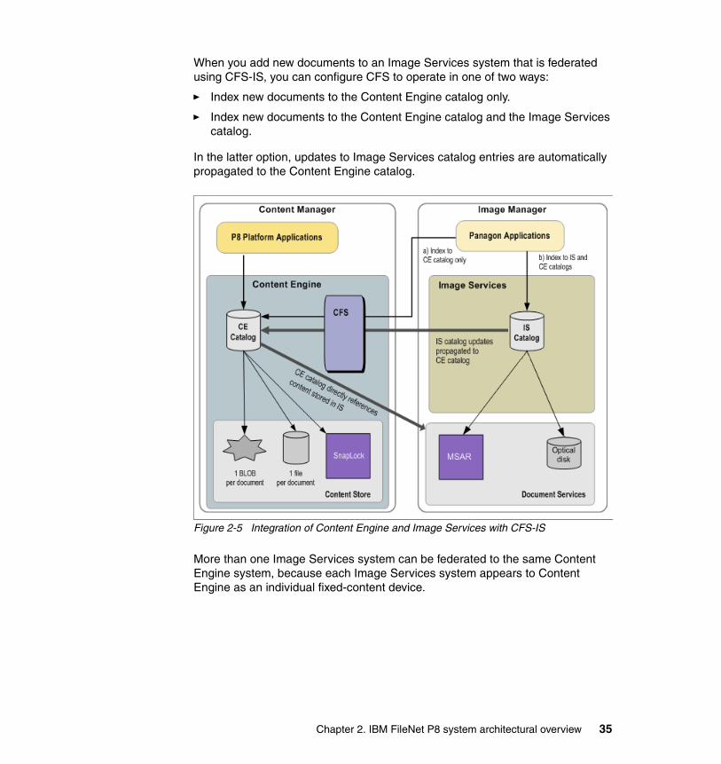
When you add new documents to an Image Services system that is federated using CFS-IS, you can configure CFS to operate in one of two ways:
� Index new documents to the Content Engine catalog only.
� Index new documents to the Content Engine catalog and the Image Services catalog.
In the latter option, updates to Image Services catalog entries are automatically propagated to the Content Engine catalog.
Figure 2-5 Integration of Content Engine and Image Services with CFS-IS
More than one Image Services system can be federated to the same Content Engine system, because each Image Services system appears to Content Engine as an individual fixed-content device.
Chapter 2. IBM FileNet P8 system architectural overview 35

2.6 Content Search Engine
Content Search Engine (CSE) provides the ability to search for documents within Content Engine based on the content of the documents. It performs two basic functions:
� Full-text indexing: New documents that are added to the Content Engine repository can be full-text indexed. That is, the documents are scanned to determine individual words that are found throughout the documents. The administrator can define a list of common words that are not to be indexed (also known as the Excluded Word List); the use of this list greatly reduces both the size of the indexes and the time that it takes to index each document.
� Search, also known as Content Based Retrieval (CBR): This function identifies the documents whose content and properties match a given search query.
In defining a search template, a user can specify a search for one or more keywords, possibly also with conditional or alternative requirements, such as ‘high NEAR availability OR HA”. Search capabilities also include the ability to account for misspelled words, typographical errors, phonetic searching, word stem searching, synonym expansion, and wildcard searching, based on the search language that has been configured. Other important aspects of the search function include:
� A single search can span multiple object stores across databases. This type of search is known as a Cross Repository Search (CRS). A Cross Repository Search is specified in Workplace simply by including more than one object store in the list of search targets.
� Workplace users can search for documents, folders, and custom objects. Searches can be designed to specify multiple folders, including a common folder name used in multiple object stores. Search templates can be constructed using a Query Builder, or more complex searches can be specified using the Verity Query Language (VQL).
� Content searches return matches not only on content but also on properties enabled for full-text indexing.
� Search results can be ranked automatically by relevancy.
� Searches can use language-specific processing and indexing.
� Bulk operations can be performed on search results in IBM FileNet Enterprise Manager, where the operations can be scripted, or selected from a set of predefined operations, such as delete, cancel checkout, file, unfile, and change security.
36 IBM High Availability Solution for IBM FileNet P8 Systems
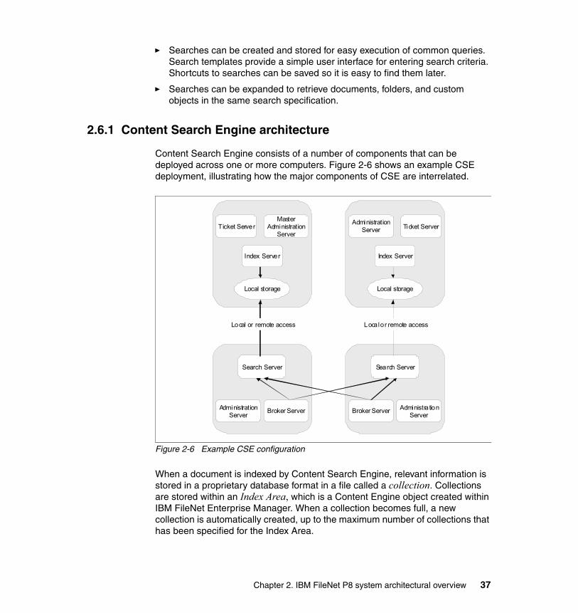
� Searches can be created and stored for easy execution of common queries. Search templates provide a simple user interface for entering search criteria. Shortcuts to searches can be saved so it is easy to find them later.
� Searches can be expanded to retrieve documents, folders, and custom objects in the same search specification.
2.6.1 Content Search Engine architecture
Content Search Engine consists of a number of components that can be deployed across one or more computers. Figure 2-6 shows an example CSE deployment, illustrating how the major components of CSE are interrelated.
Figure 2-6 Example CSE configuration
When a document is indexed by Content Search Engine, relevant information is stored in a proprietary database format in a file called a collection. Collections are stored within an Index Area, which is a Content Engine object created within IBM FileNet Enterprise Manager. When a collection becomes full, a new collection is automatically created, up to the maximum number of collections that has been specified for the Index Area.
Ticket ServerMaster
AdministrationServer
Index Server
Local storage
Ticket ServerAdministration
Server
Index Server
Local storage
Broker ServerAdministrationServer
Search Server
Broker Server Administra tionServer
Search Server
Local or remote access Local or remote access
Chapter 2. IBM FileNet P8 system architectural overview 37

To initiate a request for Content Search Engine to index a document, Content Engine copies the document’s content to a temporary area, and then it submits a request to a Content Search Engine Index Server to index that document. In IBM FileNet Content Manager Version 4.0 or prior, if there are multiple Content Engines in a farm environment, you need to manually set one Content Engine to initiate the index request. This unique Content Engine is designated by setting its EnableDispatcher configuration parameter to true. Starting from Version 4.5, the system automatically assign a Content Engine to perform the task. So, if this Content Engine fails, another Content Engine from the farm will take over automatically.
If the Content Search Engine Indexing Servers are down or unavailable, Content Engine queues up requests to index documents, up to a maximum of 100,000 documents. Under normal circumstances, therefore, the unavailability of the Content Search Engine server does not prevent ingestion of new documents into Content Engine. Monitoring to insure that the CSE Indexing Servers are up and running is therefore an important administrative task.
Not all new documents are required to be indexed. You can configure specific document classes and properties within the document classes to be full-text indexed, and documents of other classes will not be indexed. In addition to automatic indexing of new documents, the administrator can manually submit a reindexing job from IBM FileNet Enterprise Manager for a given document class, for all documents that have been marked for indexing, or for an individual document, folder, or subclass of any base document class. For example, the administrator can manually submit a reindexing job from IBM FileNet Enterprise Manager to restore a collection that was lost because of a hardware failure. During the time that documents are being reindexed, search queries can still be performed against the existing collections. When the newly created collections are ready, the old ones are deleted and the new ones become active. Reindexing jobs are typically time-consuming, so we recommend performing this task during non-peak business hours.
The following sections describe each of the components of the Content Search Engine software. Although the term “server” is used for these components, each one is really a service, and within limits, each one can be deployed separately, helping to achieve scalability and availability requirements. In a minimal configuration, all of these services can be deployed on a single host computer, as in the configuration employed for this book. However, for scalability purposes, many clients spread these services across multiple host computers (or logical equivalents, such as logical partitions (LPARs) as is done in the configuration used for this book). The services that require the most compute resources are the Index Servers and the Search Servers. Chapter 3, “High availability strategies for IBM FileNet P8 systems” on page 43 discusses the high availability considerations and the requirements for the components.
38 IBM High Availability Solution for IBM FileNet P8 Systems
2.6.2 K2 Master Administration Server
For every Content Search Engine installation, there must be exactly one K2 Master Administration Server running. This server maintains information for all the other Content Search Engine server components. When Content Search Engine configuration changes (for instance, a new Search Server is added), the Master Administration Server updates itself and all of the other K2 Administration Servers so that they have the latest configuration settings. The Administration Servers also synchronize periodically with the Master Administration Server, upon startup and every 15 minutes thereafter.
An installation of a Master Administration Server and all the related services (which can be on the same or on remote hosts) is referred to as an Autonomy K2 domain.
2.6.3 K2 Administration Server
Only one host computer within a K2 domain runs the Master Administration Server at a given time. Every other host computer in the K2 domain instead runs the K2 Administration Server.
Administration Server monitors the health of the Content Search Engine components installed on its host machine. In addition, Administration Servers can transfer configuration files that are used by the Content Search Engine system from one Content Search Engine host to another Content Search Engine host in order to propagate configuration changes.
Administration Server software is automatically installed when any other Content Search Engine server software is installed on a host machine. Remote Administration Servers are maintained by the Master Administration Server, including information, such as the configuration and status of a Content Search Engine installation. The information maintained by the local Administration Server is used by the other services running on the same host.
2.6.4 K2 Ticket Server
K2 Ticket Server is used for the security of the Content Search Engine system and its collection data. One or more Ticket Servers can exist in a K2 domain. The Ticket Servers store authentication information for users and grant access to the index collections accordingly. When a user authenticates to an LDAP server, the user receives a ticket. The Ticket Server gives the user access only to the part of the Content Search Engine system for which the user has the correct ticket. In the case of Content Engine, the credentials and other information that is necessary for Content Engine to connect with the Content Search Engine
Chapter 2. IBM FileNet P8 system architectural overview 39
servers are stored in the K2 domain Configuration tab of the IBM FileNet P8 domain root properties page within IBM FileNet Enterprise Manager.
2.6.5 K2 Index Server
K2 Index Server is the software application that performs full-text indexing of documents. Specifically, Index Server reads a document, breaks it down into its component words, eliminates words that are in the Excluded Word List, and then creates entries in the collection, mapping those words to the particular document. Breaking apart the document to identify its relevant keywords for indexing is called information abstraction. Index Server is capable of performing this process on a wide range of document types.
Only Index Server writes to the collection files. To do so, Index Server requires local file access to the collection files. Physically, the files do not have to reside within the computer hosting Index Server. Most commonly, especially for highly available configurations, the collection files are stored on a SAN and accessed through a Fibre Channel network. Such access creates the appearance that the files are stored on a local Small Computer System Interface (SCSI) device, which Index Server can then access. Index Server cannot access collection files through network file share, such as Common Internet File System (CIFS) or Network File System (NFS).
The properties of each Index Area specify one or more Index Servers that Content Engine can use for that Index Area. By using this list, Content Engine can pick an Index Server for each document to be indexed. Figure 2-7 on page 41 shows how Content Engine distributes indexing requests among several Index Servers.
40 IBM High Availability Solution for IBM FileNet P8 Systems
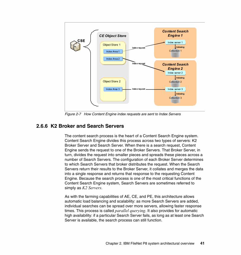
Figure 2-7 How Content Engine index requests are sent to Index Servers
2.6.6 K2 Broker and Search Servers
The content search process is the heart of a Content Search Engine system. Content Search Engine divides this process across two types of servers: K2 Broker Server and Search Server. When there is a search request, Content Engine sends the request to one of the Broker Servers. That Broker Server, in turn, divides the request into smaller pieces and spreads these pieces across a number of Search Servers. The configuration of each Broker Server determines to which Search Servers that broker distributes the request. When the Search Servers return their results to the Broker Server, it collates and merges the data into a single response and returns that response to the requesting Content Engine. Because the search process is one of the most critical functions of the Content Search Engine system, Search Servers are sometimes referred to simply as K2 Servers.
As with the farming capabilities of AE, CE, and PE, this architecture allows automatic load balancing and scalability: as more Search Servers are added, individual searches can be spread over more servers, allowing faster response times. This process is called parallel querying. It also provides for automatic high availability: if a particular Search Server fails, as long as at least one Search Server is available, the search process can still function.
CSECSECE Object Store
Content Search Engine 2
Content Search Engine 1
Index server 1Index server 1
Index server 2Index server 2
Index server 3Index server 3
Object Store 1Object Store 1
Object Store 2Object Store 2
Index request
Index request
Index request
Collection 2
Collection 3
Collection 1
Indexing
Indexing
Indexing
Index Area 3Index Area 3
Index Area 1Index Area 1
Index Area 2Index Area 2
Chapter 2. IBM FileNet P8 system architectural overview 41

Search Servers can access the collection files either as a local disk or through a network share, such as CIFS or NFS. Content Engines are automatically made aware of the Broker and Search Servers in the K2 domain by querying the Master Administration Server. When new Brokers or Search Servers are added, the Content Engines are automatically kept up-to-date.
2.6.7 Communication protocols
As a client of Content Search Engine, Content Engine connects to the Content Search Engine as a K2 Java client over TCP/IP. Installing the P8CSE client software on each of the Content Engine servers in the farm and then re-deploying the FileNetEngine.ear file installs the necessary K2 Java client files.
42 IBM High Availability Solution for IBM FileNet P8 Systems

Chapter 3. High availability strategies for IBM FileNet P8 systems
This chapter describes high availability options and strategies for IBM FileNet P8 core components.
We discuss the following topics:
� Component redundancy� Virtualization compared to high availability� Application Engine� Content Engine� Process Engine� Content Search Engine� Image Services and CFS-IS
3
© Copyright IBM Corp. 2009. All rights reserved. 43
3.1 Component redundancy
Depending on the availability requirement that is set by your business, achieving high availability requires that there is no single point of failure in an entire system, in either a hardware component or a software component. All components in the system must be redundant.
Multiple IBM FileNet P8 components work together to comprise a total solution. They depend upon other services to function in a production environment. These other services, therefore, must also be highly available to ensure the entire solution is highly available. These other services include the Network File System (NFS) service and the network service. Make sure that other services involved in the solution are also highly available.
In certain cases, a hardware component already provides internally built-in redundancy, and if so, you do not need to set up two separate hardware components to achieve high availability. For hardware components, such as storage subsystems, network load balancers, switches, and routers, it is common to use this type of internal redundancy, because these components are often used in high availability environments.
When considering making a network application highly available, determine the types of network communication that the service receives from its clients, and any connections from the software to other services. The protocols used, the caching of data on a per-session or per-user basis, and other factors dictate the best methods of achieving load balancing and high availability.
In this book, we focus on providing redundancy for IBM FileNet P8 components only.
In conjunction with this book, we recommend that you read the following publications in the area of high availability, and use them for your reference:
� IBM FileNet P8 Platform High Availability Technical Notice, GC31-5487
Consult this technical paper, especially if you are configuring a IBM FileNet P8 high availability environment using software components other than IBM software.
Note: One of the key factors in providing high availability for a system is ensuring hardware and software redundancy for all of the components that are involved in the system.
44 IBM High Availability Solution for IBM FileNet P8 Systems
� Content Manager Backup/Recovery and High Availability: Strategies, Options, and Procedures, SG24-7063
This book focuses on achieving high availability for IBM Content Manager Enterprise Edition. Although it covers another product, several of the concepts and practical procedures provided in the book can be a good reference when you design and implement your high availability system.
3.2 Virtualization compared to high availability
Platform virtualization is a technique that is used to partition a single computing system into a number of separate systems, each a software emulation of a separate computer system and operating system instance. There are a number of techniques for achieving virtualization. You can achieve virtualization through software emulation of the underlying hardware, hardware partitioning, or virtualized operating system partitioning. In the case of IBM AIX on Power hardware, the hardware is partitioned into logical partitions (LPARs).
Partitioning a single large system into effectively smaller systems offers several advantages:
� The amount of computing resources devoted to each partition can be varied dynamically as demand changes over time. This ability allows administrators to be responsive and helps to meet system-level agreements.
� Each partition can potentially run a separate operating system.
� A security breach in one partition does not affect any other partitions.
� Similarly, an application or operating system software fault in one partition does not affect the other partitions.
� By consolidating multiple servers, administrators can reduce the hardware footprint, reduce administrative and energy costs, and increase efficiency.
� Because each system runs on an abstract hardware platform, it is isolated from the particulars of any given piece of hardware. Therefore, if the hardware fails, the same virtual machine can immediately be brought back up on another virtual server.
� In the same way, a new partition can be allocated and deployed much more easily than a new hardware platform.
High availability is achieved through the elimination of all single points of failure, whether hardware or software. You can eliminate all single points of failure through the wholesale duplication of an entire computer system’s hardware and software. Often, this approach is exactly how high availability is achieved, although doing so doubles hardware and software costs. Certain hardware
Chapter 3. High availability strategies for IBM FileNet P8 systems 45
platforms have built-in redundancy by duplicating all essential components of the hardware platform, such as network ports, memory, CPU, and buses. They provide automatic failover at the hardware and software level if a component fails.
The feature of virtualization that allows a virtual machine to quickly start up on the same or another hardware platform is useful in achieving high availability, disaster recovery, or both. However, platform virtualization, by itself, does not guarantee high availability. While it can provide quick recovery from software faults, it does not eliminate the possibility of hardware failures. This problem can be overcome either through the use of two (or more) virtualized platforms, in an active/passive or an active/active configuration, or through the use of a hardware platform that includes built-in redundancy of all components so that no single points of failure exist. The configuration that is used in this book uses the latter approach, a single hardware platform that is fully redundant at the hardware level, and the use of multiple LPARs to provide software redundancy with active/passive clusters and active/active farms.
3.3 Application Engine
The Application Engine (AE) is implemented in Java as a Java 2 Platform, Enterprise Edition (J2EE) application. It therefore executes in a J2EE application server, such as IBM WebSphere Application Server Network Deployment. Clients of the Application Engine are Web browsers. They use the HTTP protocol over TCP for communication.
AE is a platform and toolkit for client applications for Content Engine (CE) and Process Engine (PE). The supported applications include Workplace, WorkplaceXT, eForms, Records Manager, and other applications. From the perspective of providing high availability, any or all of these applications are the same, so in this chapter, we refer to this platform, and whatever applications are deployed on it, as Application Engine.
The best recommended high availability strategy for Application Engine is using a load-balanced server farm, which is also known as an active/active cluster. By having all nodes active simultaneously, the best possible performance and scalability are achieved, and no hardware is left idle. An active/active configuration also provides the best possible high availability solution, because if any given node fails, the other nodes are already up, operational, and continue to process any incoming requests. The failover time consists only of the time that is required to detect that the node has failed.
In a typical installation, the Application Engine tier is placed behind an HTTP server tier that implements the WebSphere HTTP Plug-in. The HTTP servers
46 IBM High Availability Solution for IBM FileNet P8 Systems
accomplish several functions, including off-loading work from the Application Engine servers, such as the encryption and decryption of secure communications (HTTPS traffic). Performing these functions allows these servers to be placed within a DMZ area in the network, separated by firewalls from the users and other machines in the network. This approach greatly enhances the security of the network, because it minimizes the sources of connections that are allowed to reach the interior servers. The HTTP Plug-in provides a load balancing mechanism for HTTP traffic to WebSphere-based applications. It spreads the load across the available Application Engine servers, but more importantly, if one of the Application Engine servers goes down, or a new one is added to the pool of available servers, the Plug-ins automatically accommodate this change. This configuration is considered the best practice in a WebSphere environment for both high availability, scalability, and security. We implemented this configuration in our case study, with the exception that the firewalls necessary to create a DMZ area were omitted for simplicity.
To avoid introducing single points of failure, at least two HTTP servers must exist in the Web service tier. They can be front-ended by a hardware load balancer. This load balancer must either internally implement high availability through redundant hardware, or a secondary load balancer must be available, to avoid the introduction of a single point of failure.
An alternative configuration that does not provide the same level of security as the best practices configuration is to use a hardware or software load balancer directly in front of the Application Engine tier. Again, whatever load balancing mechanism is used, avoid introducing single points of failure, either hardware or software, into the system.
In order for all Application Engine nodes to be configured identically, they must share a configuration directory and bootstrap properties. In order to avoid single points of failure, this shared configuration directory must be made highly available and mounted from all Application Engine nodes. Alternatively, you can install Application Engine in a single, highly available shared location, with all Application Engine instances run from the same set of binaries and configuration files.
The Application Engine is a client of the Content Engine and the Process Engine, in both cases, using their Java APIs. The protocol used for the Application Engine to communicate with Content Engine is the Enterprise JavaBean (EJB) transport over TCP. For Process Engine communications, Common Object Request Broker Architecture (CORBA)/Internet Inter-ORB Protocol (IIOP) is used running again over TCP. We discuss the high availability considerations for these protocols in the following sections describing the high availability aspects of the Content Engine and Process Engine.
Chapter 3. High availability strategies for IBM FileNet P8 systems 47
3.3.1 Session affinity for Application Engine
When a user connects to the Application Engine, that user has to log in to the system to access the services behind it (the Content Engine and the Process Engine). The load balancer in front of the Application Engine tier can use any algorithm for load balancing these initial connections. Because Web browsers can disconnect from a server after each interaction, the Application Engine maintains the user’s state between each interaction, including the user’s logon credentials and the document with which the user is currently working. It is therefore important that the user connections are directed to the same Application Engine server consistently after the user logs in. This load balancer behavior is known as session affinity or sticky sessions.
3.4 Content Engine
Like the Application Engine, the Content Engine is implemented in Java and runs under an application server. For our case study implementation, we use IBM WebSphere Application Server Network Deployment.
The Content Engine accepts connections from clients using two separate transports, which are both carried by TCP connections:
� EJB/IIOP (Remote Method Invocation (RMI)/IIOP for WebSphere)
Only the Java applications using the Java API for Content Engine use this protocol. Application Engine, portions of IBM FileNet Records Manager, and custom Java applications that are written with the Java API use this protocol.
� Web Services Interface (WSI) over HTTP
The .Net API of Content Engine and the backward-compatible Content Engine 3.x COM API use this protocol. IBM FileNet Enterprise Manager and Process Engine use this transport to connect to the Content Engine. Portions of IBM FileNet Records Manager use it also. Third-party service-oriented architecture (SOA) applications written in a variety of languages can use this protocol, as well.
Each of these transport protocols, EJB and WSI, requires special consideration when constructing a high availability environment for Content Engine. Consequently, you must employ two load balancing mechanisms to make Content Engine highly available.
48 IBM High Availability Solution for IBM FileNet P8 Systems
3.4.1 Load balancing the EJB transport
For the EJB/IIOP transport, we recommend always using the native load balancing software that is provided with the application server if at all possible. In the case of WebSphere Application Server, this feature is the Network Deployment Workload Manager. We do not recommend using hardware or external software load balancers, which results in extremely poor performance.
3.4.2 Load balancing the WSI transport
Because the WSI transport uses the standard HTTP protocol for connections, it can be load-balanced by either a hardware or a software load balancer. In the case study configuration that is used in developing this book, we use a hardware load balancer, the F5 BIG-IP. One example of a software load balancer that you can use is the the WebSphere HTTP Plug-in, which we use for load balancing connections.
3.4.3 Session affinity for Content Engine
The Content Engine is, by design, stateless. Any request can be made to any Content Engine within a farm. Certain transactions might perform better with session affinity, but it is not proven in testing. When load balancing EJB clients, the WebSphere Network Deployment Workload Manager can provide session affinity only for statefull session beans. Because the Content Engine is designed to be stateless, it uses only stateless beans. WebSphere Application Server Network Deployment does not provide session affinity for these types of clients. Most load balancers that might be used with WSI, however, offer session affinity as an option.
While session affinity might produce higher performance for a small number of request types, it can lead to an imbalance in the load across a farm of Content Engine servers, depending upon client behavior, and this imbalance leads to lower overall performance and throughput. We therefore consider it the best practice not to attempt to perform session affinity for connections to the Content Engine for this reason.
Note: Because the EJB clients must use the client software that is provided with the application server, clients that run within an application server, such as the Application Engine, must be deployed on the same type of application server as the Content Engine.
Chapter 3. High availability strategies for IBM FileNet P8 systems 49
3.5 Process Engine
In releases prior to 4.0, Process Engine requires an active/passive cluster configuration to achieve high availability. Starting with Release 4.0, Process Engine has been redesigned to be stateless, so that an active/active server farm can be implemented. Just as with the Content Engine, this stateless configuration is the best practice configuration for achieving high availability. However, unlike Application Engine and Content Engine, Process Engine is not a J2EE application, so it does not run within an application server. Therefore, the external load balancers must be used in front of Process Engine to balance its client traffic. Up until the date that this book was written, only hardware load balancers have been tested and qualified for this purpose. For our case study, we set up an active/active cluster configuration of Process Engine using the F5 BIG-IP hardware load balancer.
The alternative high availability configuration, using an active/passive cluster, is also an option for Process Engine. It is not the best practice high availability configuration, but clients who use the IBM FileNet P8 Version 3.5 in that configuration might upgrade to Version 4.x while keeping the active/passive approach. As presented in the P8 4.x High Availability Technical Notice, GC31-5487, Microsoft Cluster Server and Veritas Cluster Server have been tested and qualified for use with Process Engine 4.x for an active/passive configuration.
Special configuration note regarding IBM FileNet Enterprise Manager: Refer to the P8 4.x High Availability Technical Notice, GC31-5487, which can be downloaded from the following URL:
http://www.ibm.com/support/docview.wss?rs=3278&uid=swg27010422
Scroll down to FileNet P8 Platform Technical Notices for this document.
Applications, such as IBM FileNet Enterprise Manager (which uses the WSI transport) that can create new document classes, must not load balance their interactions across a farm of servers. Content Engine caches the metadata state of each object store (in particular, information about the document classes defined for that object store). If a class is created on node 1, and the user immediately attempts to use that class on node 2, node 2 will not be aware of the class until its refresh interval has passed. In this scenario, it appears to the user that the class just created is unavailable. Therefore, we recommend that you configure IBM FileNet Enterprise Manager to communicate with a particular node in a server farm rather than to the virtual address of the server farm.
50 IBM High Availability Solution for IBM FileNet P8 Systems

Like Content Engine, Process Engine offers two separate: a Java API that uses the CORBA/IIOP protocol and a Web Services Interface (WSI) that uses the HTTP transport protocol. Among IBM clients of Process Engine, Application Engine (Workplace and WorkplaceXT) and custom Java applications use the Java API, while SharePoint Connector and any custom Web Service applications for Process Engine use WSI, and thus HTTP. Fortunately, load balancing for both APIs can be performed using a hardware load balancer, as long as it is capable of load balancing all ports and protocols, not just HTTP traffic over TCP. In addition to the F5 BIG-IP hardware load balancer that is used in the configuration for this book, the Cisco Local Director has also been tested with Process Engine.
3.5.1 Session affinity for Process Engine
Process Engine is stateless; therefore, any client request can be directed to any Process Engine within an active/active server farm. Unlike Application Engine, Process Engine maintains the user state within the database, so that no information is lost if a particular node in a server farm goes down. User credentials are passed with each interaction with the server so that no new logon is required if the user’s connection is redirected from one server to another server upon failover. In practice, the Java API maintains session affinity automatically as long as the original server remains available. This behavior can lead to an imbalance in load across the servers in a farm, depending upon client behavior.
3.6 Content Search Engine
The Content Search Engine (CSE) consists of a number of components, each with unique high availability considerations:
� K2 Master Administration Server� K2 Administration Servers� K2 (search) Servers� K2 Index Servers� K2 Broker Servers� K2 Ticket Servers
In a minimal configuration, all of these servers, or services, can be deployed on a single host, which is the configuration that we used for the case study for this book. However, for scalability purposes, many solutions spread these services across multiple hosts. The services that require the most computing resources are the Index Servers and the Search Servers.
Chapter 3. High availability strategies for IBM FileNet P8 systems 51
There are several potential single points of failure in this set of servers:
� The Master Administration Server� CE Dispatcher� Index Servers
Master Administration ServerFor any IBM FileNet P8 4.0 solution, there must be only one Master Administration Server; therefore, it must be paired in an active/passive cluster to achieve high availability.
DispatcherWithin the Content Engine farm, in Version 4.0.0 and Version 4.0.1, you can only designate one Content Engine as the dispatcher. Therefore, only one Content Engine can send requests for documents to be indexed to the administration servers. This functionality is enabled within the Content Engine by setting the EnableDispatcher configuration setting. Because this function must be enabled on only one Content Engine at a time, if that Content Engine fails, dispatching stops. In these versions of the Content Engine, the administrator must manually enable this setting on a separate Content Engine if the designated Content Engine fails. A potential method of automating the failover of this functionality is to include the Content Engine with this setting enabled in an active/passive cluster of the Master Administration Server. Then, if a failover happens for any reason, the passive Content Engine can be brought up with the setting enabled, and dispatching continues. As of this writing, this approach has not been tested for our case study. Beginning in Release 4.5, more than one Content Engine can have this setting enabled. Therefore, all Content Engines at the site where the Content Search Engine servers reside can submit the request, thus eliminating the single point of failure.
Index ServersEach Index Server manages one or more collections of documents, and each collection is a member of only one Index Area within the Content Engine. When a document is added to an object store, the Content Engine determines which Index Area is used to index that document, based on a number of factors that are designed to maximize performance, and thus choosing a set of collections. When a collection becomes full, a new collection is automatically created.
There are two aspects of the Index Servers that impact high availability configurations:
� K2 Index Servers manage all writes and updates to the collection files. To do so, they require local disk access to the file system housing the collections. While such a file system can be housed on a storage area network (SAN) and connected through a Fibre Channel network (so that it appears as a local disk
52 IBM High Availability Solution for IBM FileNet P8 Systems

to the server), it cannot be accessed by the Index Server through a network share, such as Network File System (NFS) or Common Internet File System (CIFS). Testing has shown that if the Index Server accesses the collections through a network share, corruption of the collection files can result.
� The Index Server is not designed to work in an active/active configuration. Therefore, for any given set of collections (Index Area), there can be only one Index Server active at a time. Therefore, for a high availability configuration, each Index Server must be paired in an active/passive cluster configuration. In order for the passive node to be able to access the collections as local storage, it is also therefore necessary to store the collections on a SAN and access them through a Fibre Channel network, so that the passive system can take control of the storage area at the time of failover.
Compared with the Index Servers, it is easy to make the Search Servers highly available. Requests for searches are sent to the Broker Servers. The Brokers farm the requests across all available Search Servers and coalesce the results before returning them to the Content Engine. This approach implements a proprietary high availability solution. The Search Servers, unlike the Index Servers, can access the collections through shared file systems. Because this file system is the local storage on the Index Server host, this approach is typically implemented by having that host share the storage using NFS or CIFS. The number of Search Servers can thus be easily scaled at any time to meet high availability and performance requirements
Figure 3-1 on page 54 illustrates a typical IBM FileNet P8 4.0 system configured for high availability, including an N+1 active/passive cluster for Content Search Engine.
Chapter 3. High availability strategies for IBM FileNet P8 systems 53
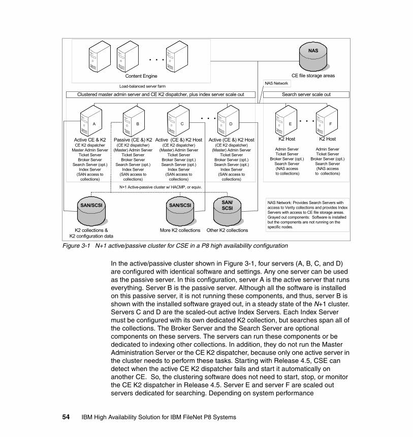
Figure 3-1 N+1 active/passive cluster for CSE in a P8 high availability configuration
In the active/passive cluster shown in Figure 3-1, four servers (A, B, C, and D) are configured with identical software and settings. Any one server can be used as the passive server. In this configuration, server A is the active server that runs everything. Server B is the passive server. Although all the software is installed on this passive server, it is not running these components, and thus, server B is shown with the installed software grayed out, in a steady state of the N+1 cluster. Servers C and D are the scaled-out active Index Servers. Each Index Server must be configured with its own dedicated K2 collection, but searches span all of the collections. The Broker Server and the Search Server are optional components on these servers. The servers can run these components or be dedicated to indexing other collections. In addition, they do not run the Master Administration Server or the CE K2 dispatcher, because only one active server in the cluster needs to perform these tasks. Starting with Release 4.5, CSE can detect when the active CE K2 dispatcher fails and start it automatically on another CE. So, the clustering software does not need to start, stop, or monitor the CE K2 dispatcher in Release 4.5. Server E and server F are scaled out servers dedicated for searching. Depending on system performance
Passive (CE &) K2(CE K2 dispatcher)
(Master) Admin ServerTicket ServerBroker Server
Search Server (opt.)Index Server
(SAN access tocollections)
N+1 Active-passive cluster w/ HACMP, or equiv.
Content Engine
Load-balanced server farm
K2 collections &K2 configuration data
K2 Host
Admin ServerTicket Server
Broker Server (opt.)Search Server(NAS access
to collections)
K2 Host
Admin ServerTicket Server
Broker Server (opt.)Search Server(NAS access
to collections)
. . .
. . .
SAN/SCSI
CE file storage areas
NAS
. . .
More K2 collections
SAN/SCSI
Other K2 collections
SAN/SCSI
Clustered master admin server and CE K2 dispatcher, plus index server scale out Search server scale out
NAS Network: Provides Search Servers with access to Verity collections and provides Index Servers with access to CE file storage areas.Grayed out components: Software is installed but the components are not running on the specific nodes.
B FE
NAS Network
Active CE & K2CE K2 dispatcher
Master Admin ServerTicket ServerBroker Server
Search Server (opt.)Index Server
(SAN access tocollections)
A
Active (CE &) K2 Host(CE K2 dispatcher)
(Master) Admin ServerTicket Server
Broker Server (opt.)Search Server (opt.)
Index Server(SAN access to
collections)
C
Active (CE &) K2 Host(CE K2 dispatcher)
(Master) Admin ServerTicket Server
Broker Server (opt.)Search Server (opt.)
Index Server(SAN access to
collections)
D
54 IBM High Availability Solution for IBM FileNet P8 Systems

requirements, you can scale out multiple servers dedicated only for indexing other collections or performing searches.
For more information about various configuration options, see the Autonomy documentation, which you can find at this Web site:
http://www.f5.com
3.7 Image Services and CFS-IS
Image Services is a collection of native programs written in C. It does not operate under an application server. The only option for high availability for Image Services is an active/passive cluster. For scalability, the separate services that comprise Image Services can be spread across multiple servers, but the high availability operation only supports a combined server with all of the services co-resident.
Tests of high availability configurations of Image Services have included Microsoft Cluster Server and Veritas Cluster Server. Detailed information about configuring Image Services for high availability is in IBM FileNet Image Services: VERITAS Cluster Server and VERITAS Volume Replicator Guidelines, GC31-5545.
For the case study that we implemented for this book, the Image Services cluster is managed by IBM PowerHA for AIX (HACMP - formerly IBM High Availability Cluster Multi-Processing).
One restriction on the Image Services configuration for high availability is that only Magnetic Storage and Retrieval (MSAR) storage is supported, not optical drives on Small Computer System Interface (SCSI) connections.
If the database goes down and comes back up (in the case of a database failover in an active/passive cluster) while Image Services is operating, versions of IS prior to 4.1.2 do not automatically reconnect to the database and continue operating. The Image Services system must be stopped and restarted manually. For this reason, for these versions, the best practice is to collocate the database and the Image Services system, so that a failover of either component (database or Image Services) automatically results in a failover of the other component. An undocumented alternative is to automate the restart of Image Services whenever the database is restarted under control of the cluster management software.
Note: In Version 4.5 and later releases, because more than one CE can dispatch indexing requests, CE is not part of the active/passive cluster. Otherwise, the configuration is identical to Figure 3-1.
Chapter 3. High availability strategies for IBM FileNet P8 systems 55
Starting with Version 4.1.2, Image Services can reconnect to the database after the connection is lost. A new setting, db_reconnect_disabled, must be disabled (set to the value “0”) to configure this new behavior. If the configuration is done this way, users who are executing a transaction at the time of a database connection loss, might receive a <121,0,41> error message, after which the transaction is automatically retried.
Image Services normally operates as a stand-alone product. When integrated with Content Engine, each instance of Content Engine includes connector software known as Content Federated Services for Image Services (CFS-IS). There is a many-to-one relationship between the Content Engine instances and a single Image Services instance. The import agent portion of CFS-IS pulls new documents from an import queue within Image Services, so this function is automatically farmed across all Content Engine instances.
There are two important differences in the 4.x version of CFS-IS compared with the 3.5 version:
� In the 3.5 version, CFS-IS was not integrated with Content Engine. For a high availability solution, while Content Engine 3.5.x can be farmed, the File Store Service (FSS) in Content Engine 3.5.x could not be farmed, only active/passive-clustered. The best solution for Content Engine 3.5 was to set up FSS on a separate computer.
� The 3.5.x version of CFS-IS required the installation of the Image Services Toolkit (ISTK) on the Content Engine hosts.
With the 4.x version of CFS-IS, these steps are no longer required.
3.8 Summary
Table 3-1 on page 57 summarizes the high availability options and recommended strategies for the main P8 server components.
56 IBM High Availability Solution for IBM FileNet P8 Systems
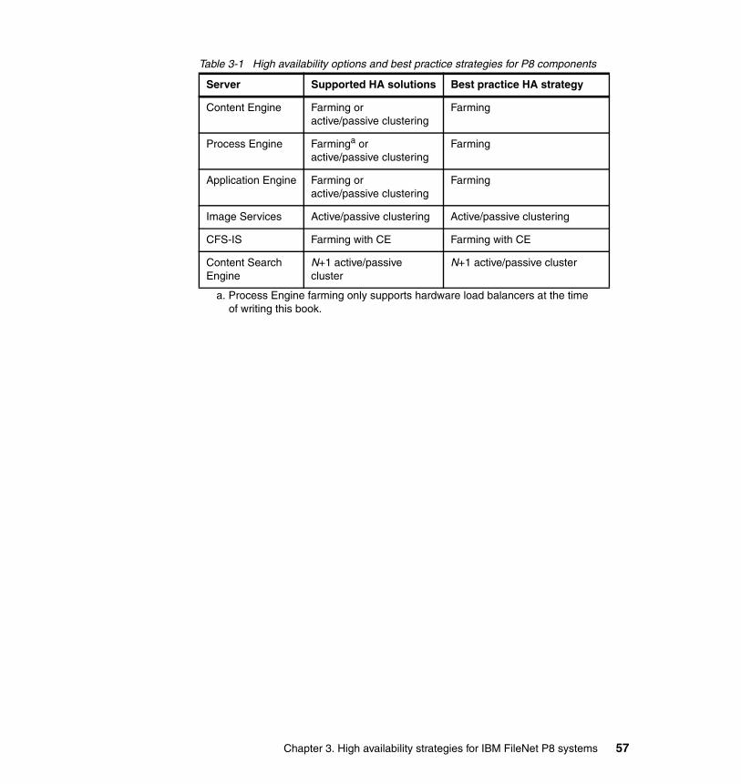
Table 3-1 High availability options and best practice strategies for P8 components
Server Supported HA solutions Best practice HA strategy
Content Engine Farming oractive/passive clustering
Farming
Process Engine Farminga or active/passive clustering
a. Process Engine farming only supports hardware load balancers at the time of writing this book.
Farming
Application Engine Farming oractive/passive clustering
Farming
Image Services Active/passive clustering Active/passive clustering
CFS-IS Farming with CE Farming with CE
Content Search Engine
N+1 active/passive cluster
N+1 active/passive cluster
Chapter 3. High availability strategies for IBM FileNet P8 systems 57

58 IBM High Availability Solution for IBM FileNet P8 Systems
Part 2 High availability implementation for IBM FileNet P8 system components
Part 2
© Copyright IBM Corp. 2009. All rights reserved. 59

60 IBM High Availability Solution for IBM FileNet P8 Systems
Chapter 4. Infrastructure setup: Introducing the case study
This chapter describes the high-level architecture of our lab environment that is used as the case study for this IBM Redbooks publication. In this case study, we set up the entire IBM FileNet P8 environment from the beginning. We use the best practices that are recommended to set up high availability (HA) for P8 whenever possible. The steps that are used for this setup are shared in the later chapters to provide a practical guide for you to follow when you plan and set up your high availability solutions. We discuss the following topics:
� Case study introduction� Hardware� Physical architecture� Architecture summary� Installation sequence reference
4
Note: The steps we take are not always the only way to accomplish the tasks. We recommend that you also consult the IBM FileNet High Availability White Paper for additional information. To access this paper, go to the FileNet Product Documentation Web site:
http://www-01.ibm.com/support/docview.wss?rs=3278&uid=swg27010422
And then, search for “High Availability” under the Technical Notices section.
© Copyright IBM Corp. 2009. All rights reserved. 61
4.1 Case study introduction
Based on the high availability strategies and best practices that were presented in Chapter 3, “High availability strategies for IBM FileNet P8 systems” on page 43, for our case study, we implement a highly available IBM FileNet P8 solution in conjunction with writing this book.
The steps involved in implementing this infrastructure are documented in detail in the remaining chapters of this book. Use these steps as sample, practical procedures that you can reference when planning, designing, and implementing high availability for your IBM FileNet P8 solution.
Many of the IBM FileNet P8 software components can be configured in multiple ways to achieve high availability. Where it was feasible and possible within our lab environment, we set up and test these configurations.
Assumptions and dependenciesFor our case study, we assume that the network infrastructure, the external storage infrastructure, and other components and services provided by the network, such as Domain Name System (DNS), Lightweight Directory Access Protocol (LDAP), security, and firewalls are highly available. Setting up those components (that are not directly within the IBM FileNet P8 environment) is outside the scope of this book. However, it is worthy to note that if any of those dependency services are not highly available, they can represent a single point of failure outside of the IBM FileNet P8 infrastructure that can cause an outage.
Work with your architecture team to ensure that there is no single point of failure outside of your IBM FileNet P8 environment.
4.2 Hardware
For our case study, we use the IBM System p5® 595 server to deploy the IBM FileNet P8 components. The hardware load balancer that we use is an F5 BIG-IP series 6800. There are other options for servers and load balancers. Check with your architecture team to determine the best servers and load balancers to use for your environment.
62 IBM High Availability Solution for IBM FileNet P8 Systems
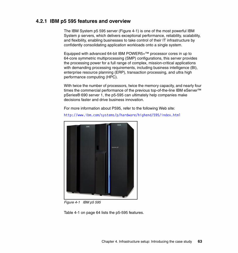
4.2.1 IBM p5 595 features and overview
The IBM System p5 595 server (Figure 4-1) is one of the most powerful IBM System p servers, which delivers exceptional performance, reliability, scalability, and flexibility, enabling businesses to take control of their IT infrastructure by confidently consolidating application workloads onto a single system.
Equipped with advanced 64-bit IBM POWER5+™ processor cores in up to 64-core symmetric multiprocessing (SMP) configurations, this server provides the processing power for a full range of complex, mission-critical applications with demanding processing requirements, including business intelligence (BI), enterprise resource planning (ERP), transaction processing, and ultra high performance computing (HPC).
With twice the number of processors, twice the memory capacity, and nearly four times the commercial performance of the previous top-of-the-line IBM eServer™ pSeries® 690 server 1, the p5-595 can ultimately help companies make decisions faster and drive business innovation.
For more information about P595, refer to the following Web site:
http://www.ibm.com/systems/p/hardware/highend/595/index.html
Figure 4-1 IBM p5 595
Table 4-1 on page 64 lists the p5-595 features.
Chapter 4. Infrastructure setup: Introducing the case study 63
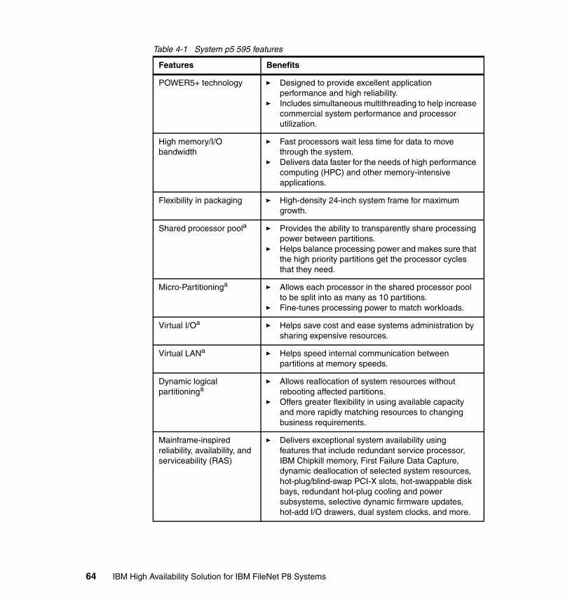
Table 4-1 System p5 595 features
Features Benefits
POWER5+ technology � Designed to provide excellent application performance and high reliability.
� Includes simultaneous multithreading to help increase commercial system performance and processor utilization.
High memory/I/O bandwidth
� Fast processors wait less time for data to move through the system.
� Delivers data faster for the needs of high performance computing (HPC) and other memory-intensive applications.
Flexibility in packaging � High-density 24-inch system frame for maximum growth.
Shared processor poola � Provides the ability to transparently share processing power between partitions.
� Helps balance processing power and makes sure that the high priority partitions get the processor cycles that they need.
Micro-Partitioninga � Allows each processor in the shared processor pool to be split into as many as 10 partitions.
� Fine-tunes processing power to match workloads.
Virtual I/Oa � Helps save cost and ease systems administration by sharing expensive resources.
Virtual LANa � Helps speed internal communication between partitions at memory speeds.
Dynamic logical partitioninga
� Allows reallocation of system resources without rebooting affected partitions.
� Offers greater flexibility in using available capacity and more rapidly matching resources to changing business requirements.
Mainframe-inspired reliability, availability, and serviceability (RAS)
� Delivers exceptional system availability using features that include redundant service processor, IBM Chipkill memory, First Failure Data Capture, dynamic deallocation of selected system resources, hot-plug/blind-swap PCI-X slots, hot-swappable disk bays, redundant hot-plug cooling and power subsystems, selective dynamic firmware updates, hot-add I/O drawers, dual system clocks, and more.
64 IBM High Availability Solution for IBM FileNet P8 Systems
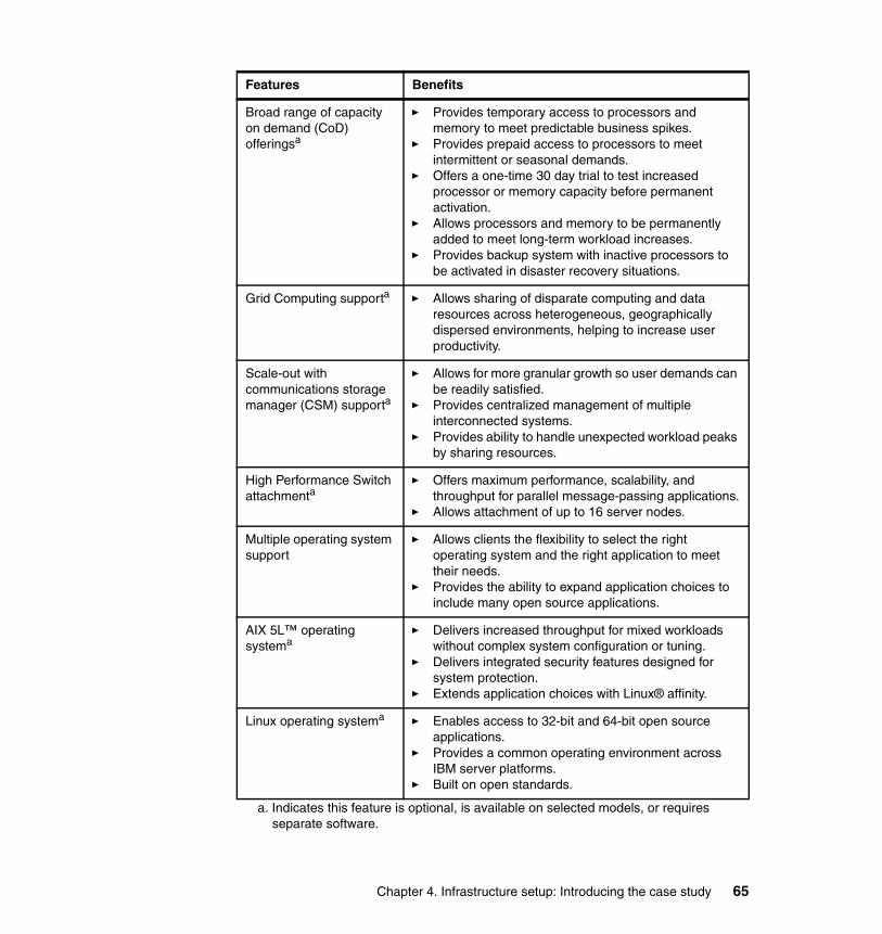
Broad range of capacity on demand (CoD) offeringsa
� Provides temporary access to processors and memory to meet predictable business spikes.
� Provides prepaid access to processors to meet intermittent or seasonal demands.
� Offers a one-time 30 day trial to test increased processor or memory capacity before permanent activation.
� Allows processors and memory to be permanently added to meet long-term workload increases.
� Provides backup system with inactive processors to be activated in disaster recovery situations.
Grid Computing supporta � Allows sharing of disparate computing and data resources across heterogeneous, geographically dispersed environments, helping to increase user productivity.
Scale-out with communications storage manager (CSM) supporta
� Allows for more granular growth so user demands can be readily satisfied.
� Provides centralized management of multiple interconnected systems.
� Provides ability to handle unexpected workload peaks by sharing resources.
High Performance Switch attachmenta
� Offers maximum performance, scalability, and throughput for parallel message-passing applications.
� Allows attachment of up to 16 server nodes.
Multiple operating system support
� Allows clients the flexibility to select the right operating system and the right application to meet their needs.
� Provides the ability to expand application choices to include many open source applications.
AIX 5L™ operating systema
� Delivers increased throughput for mixed workloads without complex system configuration or tuning.
� Delivers integrated security features designed for system protection.
� Extends application choices with Linux® affinity.
Linux operating systema � Enables access to 32-bit and 64-bit open source applications.
� Provides a common operating environment across IBM server platforms.
� Built on open standards.
a. Indicates this feature is optional, is available on selected models, or requires separate software.
Features Benefits
Chapter 4. Infrastructure setup: Introducing the case study 65
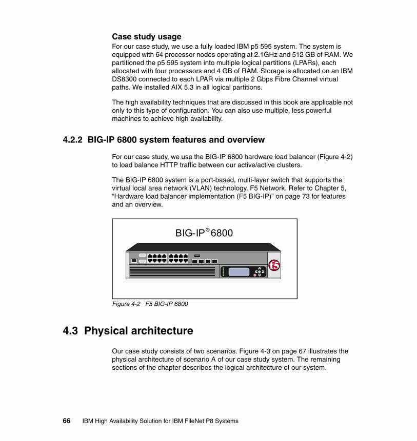
Case study usageFor our case study, we use a fully loaded IBM p5 595 system. The system is equipped with 64 processor nodes operating at 2.1GHz and 512 GB of RAM. We partitioned the p5 595 system into multiple logical partitions (LPARs), each allocated with four processors and 4 GB of RAM. Storage is allocated on an IBM DS8300 connected to each LPAR via multiple 2 Gbps Fibre Channel virtual paths. We installed AIX 5.3 in all logical partitions.
The high availability techniques that are discussed in this book are applicable not only to this type of configuration. You can also use multiple, less powerful machines to achieve high availability.
4.2.2 BIG-IP 6800 system features and overview
For our case study, we use the BIG-IP 6800 hardware load balancer (Figure 4-2) to load balance HTTP traffic between our active/active clusters.
The BIG-IP 6800 system is a port-based, multi-layer switch that supports the virtual local area network (VLAN) technology, F5 Network. Refer to Chapter 5, “Hardware load balancer implementation (F5 BIG-IP)” on page 73 for features and an overview.
Figure 4-2 F5 BIG-IP 6800
4.3 Physical architecture
Our case study consists of two scenarios. Figure 4-3 on page 67 illustrates the physical architecture of scenario A of our case study system. The remaining sections of the chapter describes the logical architecture of our system.
BIG-IP 6800®
66 IBM High Availability Solution for IBM FileNet P8 Systems
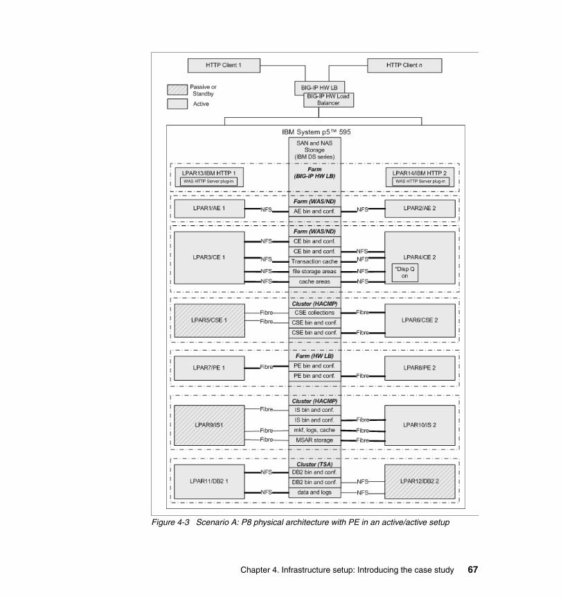
Figure 4-3 Scenario A: P8 physical architecture with PE in an active/active setup
Chapter 4. Infrastructure setup: Introducing the case study 67
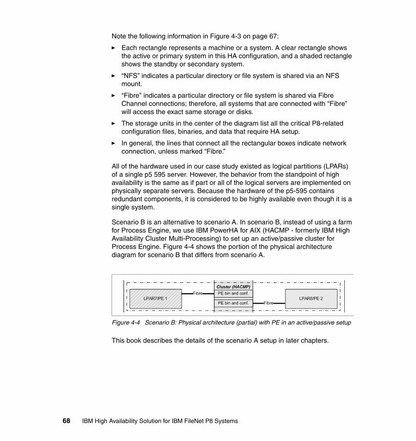
Note the following information in Figure 4-3 on page 67:
� Each rectangle represents a machine or a system. A clear rectangle shows the active or primary system in this HA configuration, and a shaded rectangle shows the standby or secondary system.
� “NFS” indicates a particular directory or file system is shared via an NFS mount.
� “Fibre” indicates a particular directory or file system is shared via Fibre Channel connections; therefore, all systems that are connected with “Fibre” will access the exact same storage or disks.
� The storage units in the center of the diagram list all the critical P8-related configuration files, binaries, and data that require HA setup.
� In general, the lines that connect all the rectangular boxes indicate network connection, unless marked “Fibre.”
All of the hardware used in our case study existed as logical partitions (LPARs) of a single p5 595 server. However, the behavior from the standpoint of high availability is the same as if part or all of the logical servers are implemented on physically separate servers. Because the hardware of the p5-595 contains redundant components, it is considered to be highly available even though it is a single system.
Scenario B is an alternative to scenario A. In scenario B, instead of using a farm for Process Engine, we use IBM PowerHA for AIX (HACMP - formerly IBM High Availability Cluster Multi-Processing) to set up an active/passive cluster for Process Engine. Figure 4-4 shows the portion of the physical architecture diagram for scenario B that differs from scenario A.
Figure 4-4 Scenario B: Physical architecture (partial) with PE in an active/passive setup
This book describes the details of the scenario A setup in later chapters.
68 IBM High Availability Solution for IBM FileNet P8 Systems
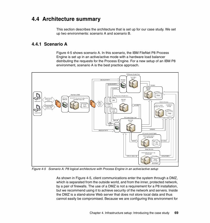
4.4 Architecture summary
This section describes the architecture that is set up for our case study. We set up two environments: scenario A and scenario B.
4.4.1 Scenario A
Figure 4-5 shows scenario A. In this scenario, the IBM FileNet P8 Process Engine is set up in an active/active mode with a hardware load balancer distributing the requests for the Process Engine. For a new setup of an IBM P8 environment, scenario A is the best practice approach.
Figure 4-5 Scenario A: P8 logical architecture with Process Engine in an active/active setup
As shown in Figure 4-5, client communications enter the system through a DMZ, which is separated from the outside world, and from the inner, protected network, by a pair of firewalls. The use of a DMZ is not a requirement for a P8 installation, but we recommend using it to achieve security of the network and servers. Inside the DMZ is a stand-alone Web server that does not store local data and thus cannot easily be compromised. Because we are configuring this environment for
Chapter 4. Infrastructure setup: Introducing the case study 69

high availability, there must be two of these Web servers to avoid having a single point of failure in the network. Because there are two servers, we use a hardware load balancer and a backup load balancer for redundancy, to route traffic to the Web servers. Because the target system to which the Web servers will connect is a WebSphere application server, the two Web servers in the DMZ have the WebSphere HTTP Plug-in installed. The plug-in handles the WebSphere-specific load balancing task.
After the traffic passes through the inner firewall, it then reaches the WebSphere cluster running the Application Engine. The communication path from the clients through the AE is always over HTTP or the equivalent HTTPS transport protocol. Application Engine then communicates with the Content Engine WebSphere cluster and the Process Engine farm via their required protocols: IIOP through a hardware load balancer for PE and EJB/IIOP; for certain applications layered on AE, Web Services Interface (WSI) over HTTP for CE; or WSI for PE. Again, for redundancy, two load balancers are shown in front of the PE farm. Note also that there is direct communication between CE and PE. This bidirectional communication always uses the Web Services protocol over HTTP. The load balancers shown in front of the PE farm will be used to balance these connections when made from a PE to the CE cluster.
The figure also shows an existing Image Services system. The content stored on this system is made accessible to the P8 clients via CFS-IS. Each CE manages its own CFS-IS connection software, so this portion of the system is automatically made redundant by the fact that there is more than one CE instance in the CE cluster. The Image Services system is made highly available via an active/passive cluster (HACMP).
Figure 4-5 on page 69 shows Image Services, CE, and PE accessing the same database server. In practice, you can separate this function into two or more database servers, depending upon capacity and scalability considerations. You can have as many database servers as one for each CE object store, plus one for the PE farm, and one for the Image Services server.
Finally, the Content Engine uses the Content Search Engine. Figure 4-5 on page 69 shows that the CSE service is made highly available by an active/passive HACMP cluster.
CE, CSE, and IS also make use of content storage, which must also be made highly available. In order for this storage to be available to all the servers, it must be made available via a file sharing protocol, such as NFS or CIFS. Therefore, this storage is frequently stored on a Network Attached Storage (NAS) device. In other cases, it might be stored on a Storage Attached Network (SAN). In this case, the storage must be shared over the network either by a “NAS Head,” a hardware device that exposes the SAN’s storage via file sharing protocols over the network, or by attaching it to a particular computer system and having that
70 IBM High Availability Solution for IBM FileNet P8 Systems
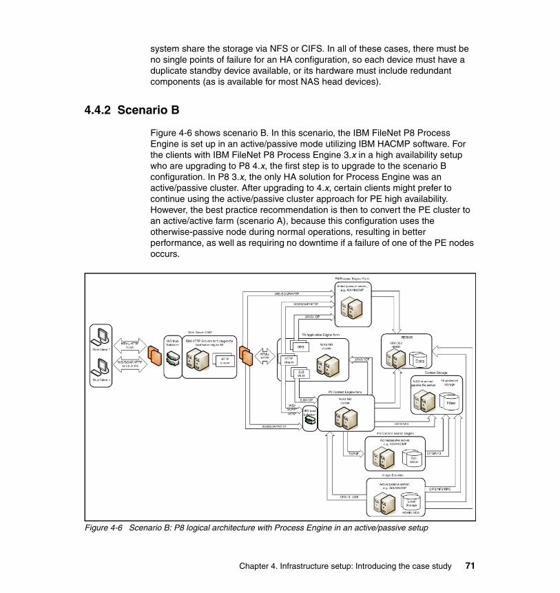
system share the storage via NFS or CIFS. In all of these cases, there must be no single points of failure for an HA configuration, so each device must have a duplicate standby device available, or its hardware must include redundant components (as is available for most NAS head devices).
4.4.2 Scenario B
Figure 4-6 shows scenario B. In this scenario, the IBM FileNet P8 Process Engine is set up in an active/passive mode utilizing IBM HACMP software. For the clients with IBM FileNet P8 Process Engine 3.x in a high availability setup who are upgrading to P8 4.x, the first step is to upgrade to the scenario B configuration. In P8 3.x, the only HA solution for Process Engine was an active/passive cluster. After upgrading to 4.x, certain clients might prefer to continue using the active/passive cluster approach for PE high availability. However, the best practice recommendation is then to convert the PE cluster to an active/active farm (scenario A), because this configuration uses the otherwise-passive node during normal operations, resulting in better performance, as well as requiring no downtime if a failure of one of the PE nodes occurs.
Figure 4-6 Scenario B: P8 logical architecture with Process Engine in an active/passive setup
Chapter 4. Infrastructure setup: Introducing the case study 71
The remainder of the configuration in scenario B is identical to the best practice approach that is illustrated in scenario A, so refer to 4.4.1, “Scenario A” on page 69.
4.5 Installation sequence reference
Although there is not a documented recommended order to install IBM FileNet P8 components, we recommend installing the components in the following order:
1. Hardware load balancer and its associated software
2. Web tier (WebSphere) and databases (DB2), which can be installed in parallel.
3. ecm_help
4. Content Engine
5. Application Engine
6. Process Engine
7. Content Search Engine
8. Image Services, which can be installed in parallel with Content Search Engine.
Hardware load balancer and its software can be installed at a later time if you do not have the hardware available at the beginning of the project.
This sequence is another possible installation order:
1. Hardware load balancer and its associated software
2. Web tier (WebSphere) and database (DB2)
3. ecm_help
4. Content Search Engine
5. Content Engine
6. Process Engine
7. Application Engine
Note: This book describes the detailed configuration for scenario A only.
72 IBM High Availability Solution for IBM FileNet P8 Systems
Chapter 5. Hardware load balancer implementation (F5 BIG-IP)
The best practice to set up Process Engine for high availability is to use a Process Engine farm. You can farm Process Engine by using hardware load balancers only. For our case study setup, therefore, we choose to use a lab-approved hardware load balancer, the BIG-IP System from F5 Network.
This chapter describes the use of the BIG-IP 6800 system, the hardware load balancer that is also known as the application delivery controller (ADC), in our IBM FileNet P8 high availability setup. For the convenience of the setup and to take advantage of the many benefits that the BIG-IP System has to offer, you can also use the load balancer for multiple IBM FileNet P8 components for high availability purposes.
We discuss the following topics:
� BIG-IP System overview� BIG-IP configuration for IBM FileNet P8� Setting up and configuring standby BIG-IP� Set up administrative partitions for P8
5
© Copyright IBM Corp. 2009. All rights reserved. 73

5.1 BIG-IP System overview
The BIG-IP System is a port-based, multilayer switch that supports virtual local area network (VLAN) technology. Because hosts within a VLAN can communicate at the data-link layer1, a BIG-IP System reduces the need for routers and IP routing on the network, which, in turn, reduces equipment costs and boosts overall network performance. At the same time, the BIG-IP System can perform IP routing at the network layer, as well as manage TCP, User Datagram Protocol (UDP), and other application protocols at the transport layer through the application layer (for example, the Web page level). These capabilities provide comprehensive and simplified traffic management and security for IBM FileNet P8 components, such as the Web servers, Content Engine, and Process Engine.
5.1.1 Core modules
BIG-IP System provides comprehensive traffic management and security for many traffic types through the following modules that are fully integrated in the device:
� BIG-IP Local Traffic Manager� BIG-IP WebAccelerator� BIG-IP Global Traffic Manager� BIG-IP Link Controller� BIG-IP Application Security Manager� BIG-IP Secure Access Manager
BIG-IP Local Traffic ManagerThe BIG-IP Local Traffic Manager features ensure that you get the most out of your network, server, and application resources. BIG-IP Local Traffic Manager removes single points of failure and virtualizes the network and applications using industry-leading layer 7 (L7) application intelligence. BIG-IP Local Traffic Manager includes rich static and dynamic load balancing methods, including Dynamic Ratio, Least Connections, and Observed Load Balancing, which track dynamic performance levels of servers in a group. These methods ensure that all sites are always on, more scalable, and easier to manage than ever before.
1 Open Systems Interconnection Basic Reference Model (OSI Model) divides network architectureinto seven abstract layers: (1) Physical, (2) Data Link, (3) Network, (4) Transport, (5) Session, (6)Presentation, and (7) Application.
74 IBM High Availability Solution for IBM FileNet P8 Systems
For more information, see the Configuration Guide for BIG-IP Local Traffic Management. You can access BIG-IP documentation from the following Web sites:
� BIG-IP System Management Guide:
https://support.f5.com/kb/en-us/products/big-ip_ltm/manuals/product/bigip9_0sys.html
� Instructions for BIG-IP 5 high availability configuration in the GUI:
https://support.f5.com/kb/en-us/products/big-ip_ltm/manuals/product/bigip9_0sys/9_0_xSystemMgmtGuide-13-1.html#wp1020826
BIG-IP WebAcceleratorBIG-IP WebAccelerator is an advanced Web application delivery solution that provides a series of intelligent technologies that overcomes performance issues involving browsers, Web application platforms, and wide area network (WAN) latency. By decreasing page download times, WebAccelerator offloads servers, decreases bandwidth usage, and ensures the productivity of application users.
BIG-IP Global Traffic ManagerThe BIG-IP Global Traffic Manager provides intelligent traffic management for high availability across multiple data centers, for managing backup and disaster recovery, and for your globally available network resources. Through the Global Traffic Manager, you can select from an array of load balancing modes, ensuring that your clients access the most responsive and robust resources at any given time. In addition, the Global Traffic Manager provides extensive monitoring capabilities so the health of any given resource is always available. For more information, see the Configuration Guide for BIG-IP Global Traffic Management.
BIG-IP Link ControllerBIG-IP Link Controller monitors the availability and performance of multiple WAN connections to intelligently manage bidirectional traffic flows to a site, providing fault-tolerant, optimized Internet access regardless of connection type or provider. The Link Controller ensures that traffic is always sent over the best available link to maximize user performance and minimize bandwidth cost to a data center. For more information, see the Configuration Guide for BIG-IP Link Controller.
BIG-IP Application Security ManagerBIG-IP Application Security Manager provides Web application protection from application layer attacks. BIG-IP Application Security Manager protects Web applications from both generalized and targeted application layer attacks, including buffer overflow, SQL injection, cross-site scripting, and parameter
Chapter 5. Hardware load balancer implementation (F5 BIG-IP) 75
tampering. For more information, see the Configuration Guide for BIG-IP Application Security Manager.
BIG-IP Secure Access ManagerBIG-IP Secure Access Manager is a high-performance, flexible security platform, providing a unified secure access solution on a single appliance. Using Secure Sockets Layer (SSL) technology for encrypted traffic, BIG-IP Secure Access Manager provides policy-based, secure access to enterprise applications for any client user, from employees, contractors, partners, suppliers, and customers to any corporate resource. BIG-IP Secure Access Manager provides end-to-end data protection for secured Web application client connectivity to enterprise applications.
5.1.2 Key benefits
BIG-IP provides many benefits to a high availability environment:
� High availability: Delivers the industry’s most advanced system to ensure that applications are always available.
� Accelerated applications: Provides unmatched control to accelerate application performance by up to 3-15x, ensuring that priority applications are served first and off-loading expensive server cycles.
� Reduced server and bandwidth cost: Triples server capacity through a rich set of infrastructure optimization capabilities, and reduces bandwidth costs by up to 80 percent through intelligent HTTP compression, bandwidth management, and more.
� Greater network and application security: From denial-of-service (DoS) attack protection to cloaking to filtering out application attacks, BIG-IP Local Traffic Manager adds critical security features that simply cannot be addressed elsewhere in the network.
� Unmatched application intelligence and control: The industry’s only solution that delivers complete application fluency, enabling network-speed full payload inspection, and programmable, event-based traffic management to understand and act upon application flows.
� Total integration for all IP applications: Provides a comprehensive solution that can integrate with all applications, not just Web-based protocols (HTTP and HTTPS). Provides organizations with a centralized solution for all IP applications, including existing and emerging applications, such as Voice over Internet Protocol (VoIP) — all in a single, unified system.
� Industry-leading performance: Delivers the industry’s fastest traffic management solution to secure, deliver, and optimize application performance. As a proven leader, BIG-IP Local Traffic Manager sets the
76 IBM High Availability Solution for IBM FileNet P8 Systems
performance bar with best-in-market SSL transactions per second (TPS), bulk encryption, and the highest concurrent SSL connections available today.
� Easy to manage, better visibility: An advanced GUI greatly simplifies product configuration, offering granular visibility into traffic and system resources, as well as support for making rapid changes across large configurations.
� Extends collaboration between network and application groups: Through partitioned views and application/protocol-specific monitors, BIG-IP Local Traffic Manager improves administrative functions and provides more application-aware traffic management.
5.2 BIG-IP configuration for IBM FileNet P8
For our high availability case study, we utilize and configure the F5 BIG-IP 6800 system for our scenario. BIG-IP is available in a variety of platforms. See your local F5 reseller professional or contact F5 directly for proper sizing. We design our deployment to load balance traffic that is running various protocols in IBM WebSphere servers, specifically Content Engine, HTTP servers for Application Engine, and Process Engine. Figure 5-1 on page 78 shows the configuration with a redundant pair of BIG-IP clusters of WebSphere Application Engine servers (AE1 and AE2), Content Engine servers (CE1 and CE2), and Process Engine servers (PE1 and PE2).
Chapter 5. Hardware load balancer implementation (F5 BIG-IP) 77
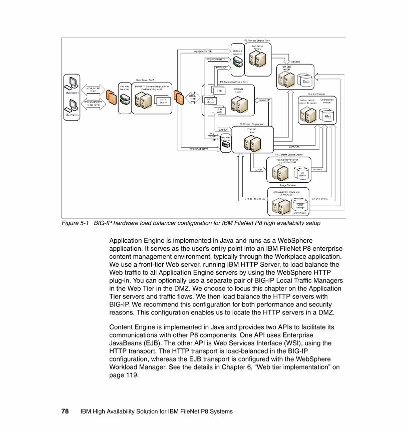
Figure 5-1 BIG-IP hardware load balancer configuration for IBM FileNet P8 high availability setup
Application Engine is implemented in Java and runs as a WebSphere application. It serves as the user’s entry point into an IBM FileNet P8 enterprise content management environment, typically through the Workplace application. We use a front-tier Web server, running IBM HTTP Server, to load balance the Web traffic to all Application Engine servers by using the WebSphere HTTP plug-in. You can optionally use a separate pair of BIG-IP Local Traffic Managers in the Web Tier in the DMZ. We choose to focus this chapter on the Application Tier servers and traffic flows. We then load balance the HTTP servers with BIG-IP. We recommend this configuration for both performance and security reasons. This configuration enables us to locate the HTTP servers in a DMZ.
Content Engine is implemented in Java and provides two APIs to facilitate its communications with other P8 components. One API uses Enterprise JavaBeans (EJB). The other API is Web Services Interface (WSI), using the HTTP transport. The HTTP transport is load-balanced in the BIG-IP configuration, whereas the EJB transport is configured with the WebSphere Workload Manager. See the details in Chapter 6, “Web tier implementation” on page 119.
78 IBM High Availability Solution for IBM FileNet P8 Systems

Process Engine provides workflow management capabilities. Process Engine is implemented in C and supports a load-balanced farm configuration. We use BIG-IP to load balance two Process Engine instances in the high availability configuration.
The following sections provide the detailed setup procedures for BIG-IP in the IBM FileNet P8 high availability solution. Follow the sections in order, because the sections include the dependencies.
These steps are required to configure the load balancer for our system:
1. Configuring the self IP and virtual local area networks.2. Define the pools for Application Engine, Content Engine, and Process Engine.3. Define the virtual servers for Application Engine, Content Engine, and
Process Engine.4. Enable session affinity for Content Engine in BIG-IP.5. Configure health monitors for Application Engine, Content Engine, and
Process Engine.
5.2.1 Configuring the self IP and virtual local area networks
When a new BIG-IP System is first installed, you must use the administrative console to perform any tasks. The administrative console is a Web application running in a browser. You can access the application in one of the two ways:
� Be on the same network (192.168.1.xxx) as the console interface.� Configure a self IP on one of the lights-out management network ports.
The lights-out management system provides the ability to remotely manage certain aspects of the operation of the hardware unit and the BIG-IP traffic management operating system in the event that the traffic management software becomes incapacitated.
The lights-out management system consists of the following elements:
� Switch card control processor (SCCP)
The hardware that provides the hardware control over the whole unit.
� Host console shell (hostconsh)
The shell that provides access to the command menu.
� Command menu
The menu that contains the options for lights-out management.
� Traffic management operating system
The software that you configure to manage the traffic for your site.
Chapter 5. Hardware load balancer implementation (F5 BIG-IP) 79
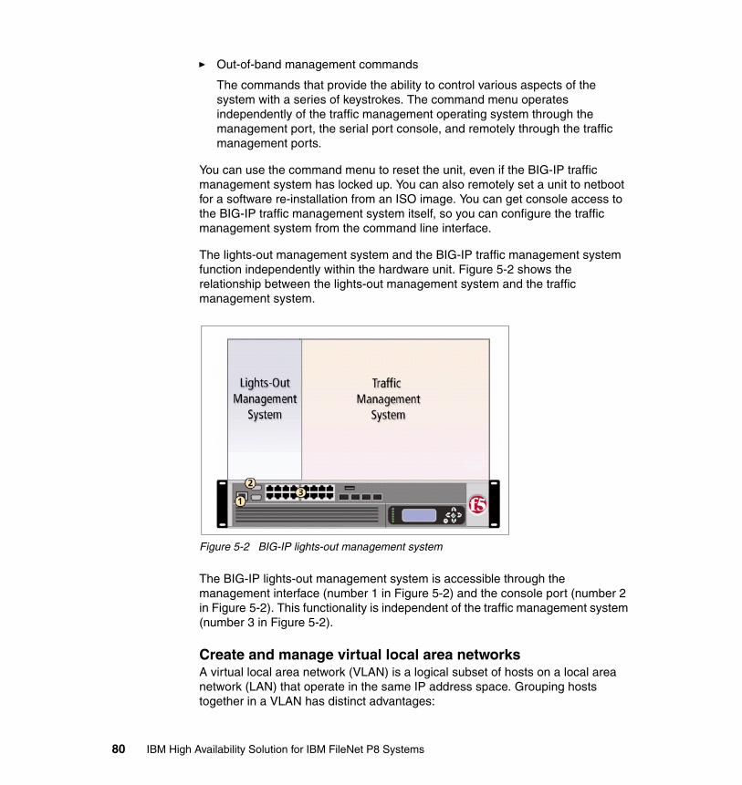
� Out-of-band management commands
The commands that provide the ability to control various aspects of the system with a series of keystrokes. The command menu operates independently of the traffic management operating system through the management port, the serial port console, and remotely through the traffic management ports.
You can use the command menu to reset the unit, even if the BIG-IP traffic management system has locked up. You can also remotely set a unit to netboot for a software re-installation from an ISO image. You can get console access to the BIG-IP traffic management system itself, so you can configure the traffic management system from the command line interface.
The lights-out management system and the BIG-IP traffic management system function independently within the hardware unit. Figure 5-2 shows the relationship between the lights-out management system and the traffic management system.
Figure 5-2 BIG-IP lights-out management system
The BIG-IP lights-out management system is accessible through the management interface (number 1 in Figure 5-2) and the console port (number 2 in Figure 5-2). This functionality is independent of the traffic management system (number 3 in Figure 5-2).
Create and manage virtual local area networksA virtual local area network (VLAN) is a logical subset of hosts on a local area network (LAN) that operate in the same IP address space. Grouping hosts together in a VLAN has distinct advantages:
80 IBM High Availability Solution for IBM FileNet P8 Systems
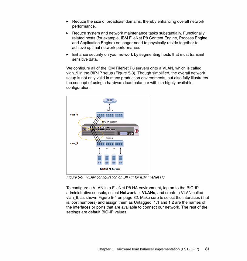
� Reduce the size of broadcast domains, thereby enhancing overall network performance.
� Reduce system and network maintenance tasks substantially. Functionally related hosts (for example, IBM FileNet P8 Content Engine, Process Engine, and Application Engine) no longer need to physically reside together to achieve optimal network performance.
� Enhance security on your network by segmenting hosts that must transmit sensitive data.
We configure all of the IBM FileNet P8 servers onto a VLAN, which is called vlan_9 in the BIP-IP setup (Figure 5-3). Though simplified, the overall network setup is not only valid in many production environments, but also fully illustrates the concept of using a hardware load balancer within a highly available configuration.
Figure 5-3 VLAN configuration on BIP-IP for IBM FileNet P8
To configure a VLAN in a FileNet P8 HA environment, log on to the BIG-IP administrative console, select Network → VLANs, and create a VLAN called vlan_9, as shown Figure 5-4 on page 82. Make sure to select the interfaces (that is, port numbers) and assign them as Untagged. 1.1 and 1.2 are the names of the interfaces or ports that are available to connect our network. The rest of the settings are default BIG-IP values.
Chapter 5. Hardware load balancer implementation (F5 BIG-IP) 81
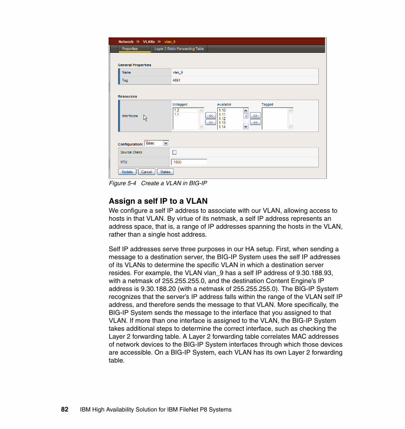
Figure 5-4 Create a VLAN in BIG-IP
Assign a self IP to a VLANWe configure a self IP address to associate with our VLAN, allowing access to hosts in that VLAN. By virtue of its netmask, a self IP address represents an address space, that is, a range of IP addresses spanning the hosts in the VLAN, rather than a single host address.
Self IP addresses serve three purposes in our HA setup. First, when sending a message to a destination server, the BIG-IP System uses the self IP addresses of its VLANs to determine the specific VLAN in which a destination server resides. For example, the VLAN vlan_9 has a self IP address of 9.30.188.93, with a netmask of 255.255.255.0, and the destination Content Engine’s IP address is 9.30.188.20 (with a netmask of 255.255.255.0). The BIG-IP System recognizes that the server’s IP address falls within the range of the VLAN self IP address, and therefore sends the message to that VLAN. More specifically, the BIG-IP System sends the message to the interface that you assigned to that VLAN. If more than one interface is assigned to the VLAN, the BIG-IP System takes additional steps to determine the correct interface, such as checking the Layer 2 forwarding table. A Layer 2 forwarding table correlates MAC addresses of network devices to the BIG-IP System interfaces through which those devices are accessible. On a BIG-IP System, each VLAN has its own Layer 2 forwarding table.
82 IBM High Availability Solution for IBM FileNet P8 Systems
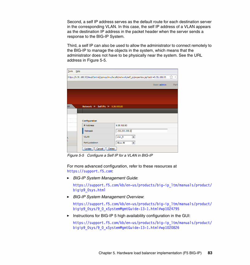
Second, a self IP address serves as the default route for each destination server in the corresponding VLAN. In this case, the self IP address of a VLAN appears as the destination IP address in the packet header when the server sends a response to the BIG-IP System.
Third, a self IP can also be used to allow the administrator to connect remotely to the BIG-IP to manage the objects in the system, which means that the administrator does not have to be physically near the system. See the URL address in Figure 5-5.
Figure 5-5 Configure a Self IP for a VLAN in BIG-IP
For more advanced configuration, refer to these resources at https://support.f5.com:
� BIG-IP System Management Guide:
https://support.f5.com/kb/en-us/products/big-ip_ltm/manuals/product/bigip9_0sys.html
� BIG-IP System Management Overview:
https://support.f5.com/kb/en-us/products/big-ip_ltm/manuals/product/bigip9_0sys/9_0_xSystemMgmtGuide-13-1.html#wp1024795
� Instructions for BIG-IP 5 high availability configuration in the GUI:
https://support.f5.com/kb/en-us/products/big-ip_ltm/manuals/product/bigip9_0sys/9_0_xSystemMgmtGuide-13-1.html#wp1020826
Chapter 5. Hardware load balancer implementation (F5 BIG-IP) 83
5.2.2 Define the pools for Application Engine, Content Engine, and Process Engine
A pool is composed of a group of network devices (called members). The BIG-IP System load balances requests to the nodes within a pool based on the load balancing method and persistence method that you choose when you create the pool or edit its properties.
The core FileNet P8 servers that use a load balancing method are HTTP Servers for Application Engine (AE), Content Engine (CE), and Process Engine (PE). In the FIleNet P8 HA environment, we configure the following pools:
� p8ae_pool, for Application Engine nodes, AE1 and AE2
� p8ce_pool, for Content Engine nodes, CE1 and CE2
� p8pe_pool, for Process Engine nodes, PE1 and PE2
Other servers can also be configured as a pool, or you can use a pool as additional monitors to report a system’s status, as we show in 5.4, “Set up administrative partitions for P8” on page 114.
To create a pool using the BIG-IP Configuration utility, perform the following steps (for brevity, we use CE as the example):
1. In the navigation pane, click Pools. The Pools window opens.
2. Click Add. The Add Pool window displays.
3. In the Name field, enter a name for your pool. In our example, we use p8ce_pool, for the CE servers.
4. In the Load Balancing Method field, select the preferred load balancing method. We recommend one of the following load balancing methods, although various load balancing methods can yield optimal results for a particular network:
– Least Connections
In Least Connections mode, the BIG-IP System passes a new connection to the node that has the least number of current connections. Least Connections mode works best in environments where the servers (or other equipment) that you are load balancing have similar capabilities.
– Fastest
In Fastest mode, the BIG-IP System passes a new connection based on the fastest response of all currently active nodes. Fastest mode can be particularly useful in environments where nodes are distributed across separate logical networks, or where the servers have varying levels of performance.
84 IBM High Availability Solution for IBM FileNet P8 Systems
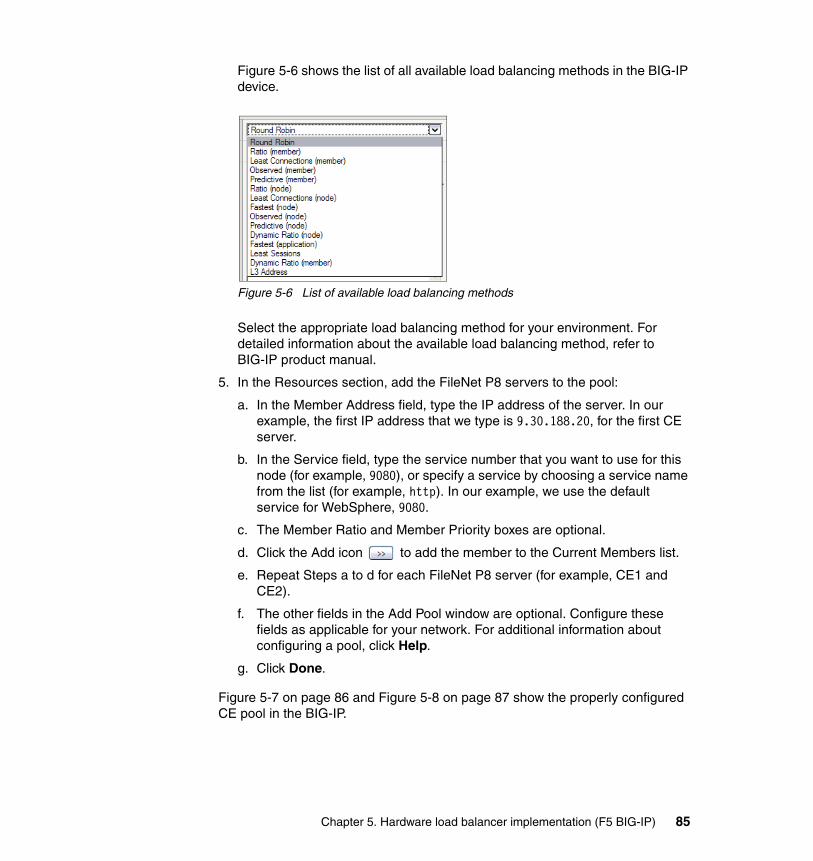
Figure 5-6 shows the list of all available load balancing methods in the BIG-IP device.
Figure 5-6 List of available load balancing methods
Select the appropriate load balancing method for your environment. For detailed information about the available load balancing method, refer to BIG-IP product manual.
5. In the Resources section, add the FileNet P8 servers to the pool:
a. In the Member Address field, type the IP address of the server. In our example, the first IP address that we type is 9.30.188.20, for the first CE server.
b. In the Service field, type the service number that you want to use for this node (for example, 9080), or specify a service by choosing a service name from the list (for example, http). In our example, we use the default service for WebSphere, 9080.
c. The Member Ratio and Member Priority boxes are optional.
d. Click the Add icon to add the member to the Current Members list.
e. Repeat Steps a to d for each FileNet P8 server (for example, CE1 and CE2).
f. The other fields in the Add Pool window are optional. Configure these fields as applicable for your network. For additional information about configuring a pool, click Help.
g. Click Done.
Figure 5-7 on page 86 and Figure 5-8 on page 87 show the properly configured CE pool in the BIG-IP.
Chapter 5. Hardware load balancer implementation (F5 BIG-IP) 85
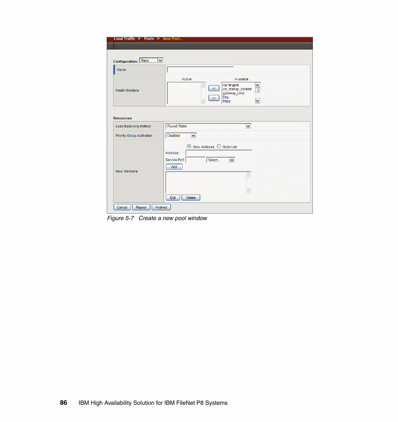
Figure 5-7 Create a new pool window
86 IBM High Availability Solution for IBM FileNet P8 Systems
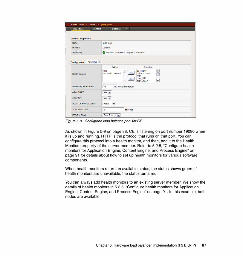
Figure 5-8 Configured load balance pool for CE
As shown in Figure 5-9 on page 88, CE is listening on port number 19080 when it is up and running. HTTP is the protocol that runs on that port. You can configure this protocol into a health monitor, and then, add it to the Health Monitors property of the server member. Refer to 5.2.5, “Configure health monitors for Application Engine, Content Engine, and Process Engine” on page 91 for details about how to set up health monitors for various software components.
When health monitors return an available status, the status shows green. If health monitors are unavailable, the status turns red.
You can always add health monitors to an existing server member. We show the details of health monitors in 5.2.5, “Configure health monitors for Application Engine, Content Engine, and Process Engine” on page 91. In this example, both nodes are available.
Chapter 5. Hardware load balancer implementation (F5 BIG-IP) 87
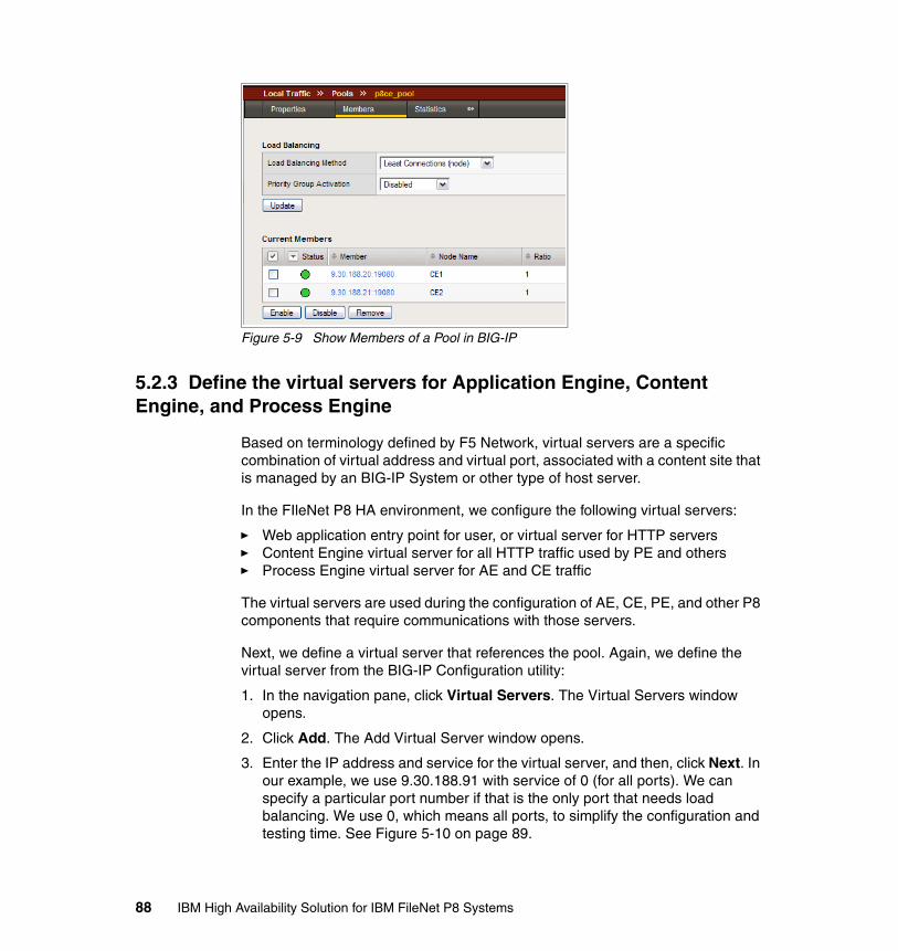
Figure 5-9 Show Members of a Pool in BIG-IP
5.2.3 Define the virtual servers for Application Engine, Content Engine, and Process Engine
Based on terminology defined by F5 Network, virtual servers are a specific combination of virtual address and virtual port, associated with a content site that is managed by an BIG-IP System or other type of host server.
In the FIleNet P8 HA environment, we configure the following virtual servers:
� Web application entry point for user, or virtual server for HTTP servers� Content Engine virtual server for all HTTP traffic used by PE and others� Process Engine virtual server for AE and CE traffic
The virtual servers are used during the configuration of AE, CE, PE, and other P8 components that require communications with those servers.
Next, we define a virtual server that references the pool. Again, we define the virtual server from the BIG-IP Configuration utility:
1. In the navigation pane, click Virtual Servers. The Virtual Servers window opens.
2. Click Add. The Add Virtual Server window opens.
3. Enter the IP address and service for the virtual server, and then, click Next. In our example, we use 9.30.188.91 with service of 0 (for all ports). We can specify a particular port number if that is the only port that needs load balancing. We use 0, which means all ports, to simplify the configuration and testing time. See Figure 5-10 on page 89.
88 IBM High Availability Solution for IBM FileNet P8 Systems
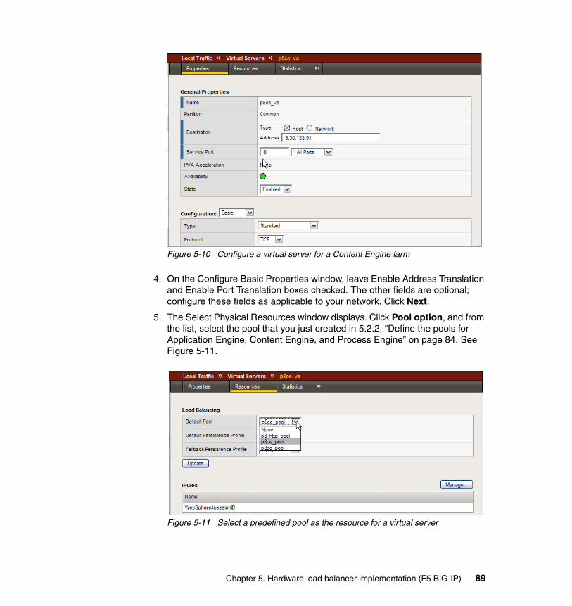
Figure 5-10 Configure a virtual server for a Content Engine farm
4. On the Configure Basic Properties window, leave Enable Address Translation and Enable Port Translation boxes checked. The other fields are optional; configure these fields as applicable to your network. Click Next.
5. The Select Physical Resources window displays. Click Pool option, and from the list, select the pool that you just created in 5.2.2, “Define the pools for Application Engine, Content Engine, and Process Engine” on page 84. See Figure 5-11.
Figure 5-11 Select a predefined pool as the resource for a virtual server
Chapter 5. Hardware load balancer implementation (F5 BIG-IP) 89
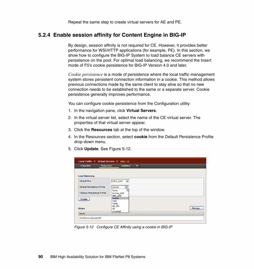
Repeat the same step to create virtual servers for AE and PE.
5.2.4 Enable session affinity for Content Engine in BIG-IP
By design, session affinity is not required for CE. However, it provides better performance for WSI/HTTP applications (for example, PE). In this section, we show how to configure the BIG-IP System to load balance CE servers with persistence on the pool. For optimal load balancing, we recommend the Insert mode of F5’s cookie persistence for BIG-IP Version 4.0 and later.
Cookie persistence is a mode of persistence where the local traffic management system stores persistent connection information in a cookie. This method allows previous connections made by the same client to stay alive so that no new connection needs to be established to the same or a separate server. Cookie persistence generally improves performance.
You can configure cookie persistence from the Configuration utility:
1. In the navigation pane, click Virtual Servers.
2. In the virtual server list, select the name of the CE virtual server. The properties of that virtual server appear.
3. Click the Resources tab at the top of the window.
4. In the Resources section, select cookie from the Default Persistence Profile drop-down menu.
5. Click Update. See Figure 5-12.
Figure 5-12 Configure CE Affinity using a cookie in BIG-IP
90 IBM High Availability Solution for IBM FileNet P8 Systems
For more information about selecting the appropriate persistence profile, refer to the BIG-IP Network and System Management Guide.
5.2.5 Configure health monitors for Application Engine, Content Engine, and Process Engine
A health monitor checks a node to see if it is up and functioning for a given service. If the node fails the check, it is marked down. Multiple monitors exist in BIG-IP for checking various services. We create FileNet P8 specific health monitors to monitor P8 servers. Table 5-1 lists the FileNet P8 specific health monitors used.
Table 5-1 New monitors created for FileNet P8 servers in BIG-IP
HTTP Server health monitorThe default http health monitor in BIG-IP sends a http request to the root of the Web server running the virtual server. In our case, the IBM HTTP Server, when running, displays the welcome page as shown in Figure 5-13 on page 92.
FileNet P8 Server Health monitors used Notes
HTTP Servers for AE http BIG-IP built-in monitor
CE httpce_startup_context
BIG-IP built-in monitorCustom monitor
PE p8pe_32777p8pe_32776p8pe_32776_http
Custom monitorCustom monitorCustom monitor
Chapter 5. Hardware load balancer implementation (F5 BIG-IP) 91
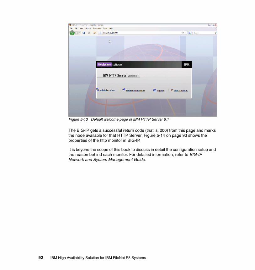
Figure 5-13 Default welcome page of IBM HTTP Server 6.1
The BIG-IP gets a successful return code (that is, 200) from this page and marks the node available for that HTTP Server. Figure 5-14 on page 93 shows the properties of the http monitor in BIG-IP.
It is beyond the scope of this book to discuss in detail the configuration setup and the reason behind each monitor. For detailed information, refer to BIG-IP Network and System Management Guide.
92 IBM High Availability Solution for IBM FileNet P8 Systems
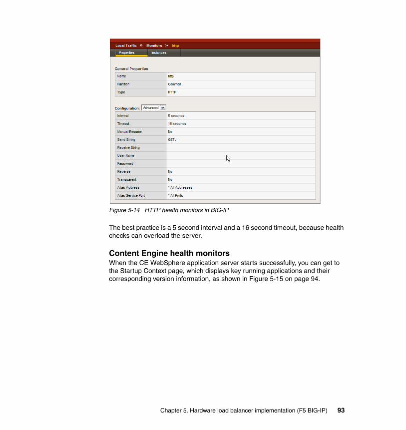
Figure 5-14 HTTP health monitors in BIG-IP
The best practice is a 5 second interval and a 16 second timeout, because health checks can overload the server.
Content Engine health monitorsWhen the CE WebSphere application server starts successfully, you can get to the Startup Context page, which displays key running applications and their corresponding version information, as shown in Figure 5-15 on page 94.
Chapter 5. Hardware load balancer implementation (F5 BIG-IP) 93
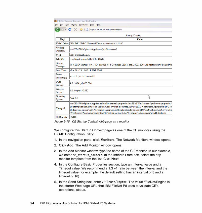
Figure 5-15 CE Startup Context Web page as a monitor
We configure this Startup Context page as one of the CE monitors using the BIG-IP Configuration utility:
1. In the navigation pane, click Monitors. The Network Monitors window opens.
2. Click Add. The Add Monitor window opens.
3. In the Add Monitor window, type the name of the CE monitor. In our example, we enter ce_startup_context. In the Inherits From box, select the http monitor template from the list. Click Next.
4. In the Configure Basic Properties section, type an Interval value and a Timeout value. We recommend a 1:3 +1 ratio between the interval and the timeout value (for example, the default setting has an interval of 5 and a timeout of 16).
5. In the Send String box, enter /FileNet/Engine. The value /FileNet/Engine is the starter Web page URL that IBM FileNet P8 uses to validate CE’s operational status.
94 IBM High Availability Solution for IBM FileNet P8 Systems
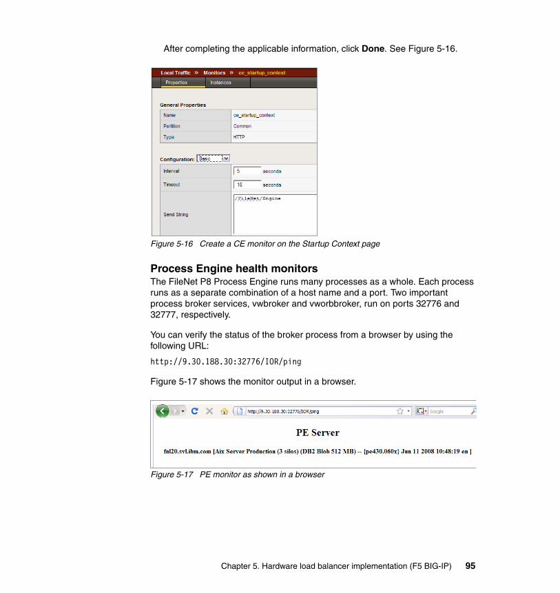
After completing the applicable information, click Done. See Figure 5-16.
Figure 5-16 Create a CE monitor on the Startup Context page
Process Engine health monitorsThe FileNet P8 Process Engine runs many processes as a whole. Each process runs as a separate combination of a host name and a port. Two important process broker services, vwbroker and vworbbroker, run on ports 32776 and 32777, respectively.
You can verify the status of the broker process from a browser by using the following URL:
http://9.30.188.30:32776/IOR/ping
Figure 5-17 shows the monitor output in a browser.
Figure 5-17 PE monitor as shown in a browser
Chapter 5. Hardware load balancer implementation (F5 BIG-IP) 95
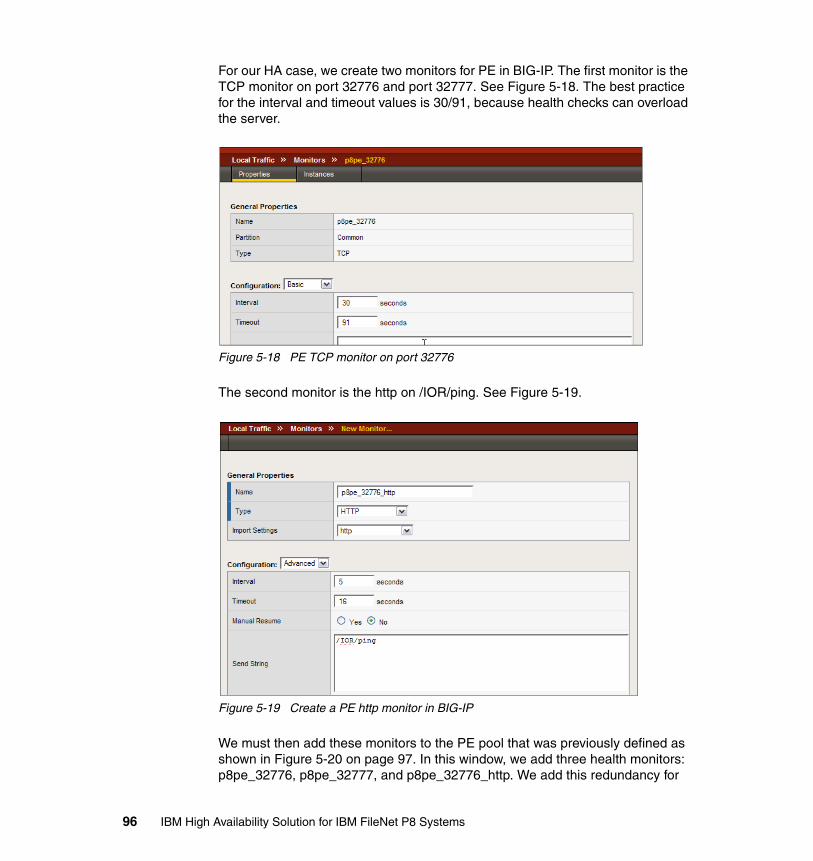
For our HA case, we create two monitors for PE in BIG-IP. The first monitor is the TCP monitor on port 32776 and port 32777. See Figure 5-18. The best practice for the interval and timeout values is 30/91, because health checks can overload the server.
Figure 5-18 PE TCP monitor on port 32776
The second monitor is the http on /IOR/ping. See Figure 5-19.
Figure 5-19 Create a PE http monitor in BIG-IP
We must then add these monitors to the PE pool that was previously defined as shown in Figure 5-20 on page 97. In this window, we add three health monitors: p8pe_32776, p8pe_32777, and p8pe_32776_http. We add this redundancy for
96 IBM High Availability Solution for IBM FileNet P8 Systems
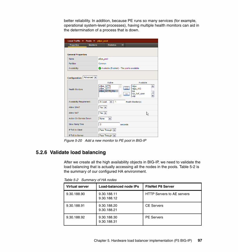
better reliability. In addition, because PE runs so many services (for example, operational system-level processes), having multiple health monitors can aid in the determination of a process that is down.
Figure 5-20 Add a new monitor to PE pool in BIG-IP
5.2.6 Validate load balancing
After we create all the high availability objects in BIG-IP, we need to validate the load balancing that is actually accessing all the nodes in the pools. Table 5-2 is the summary of our configured HA environment.
Table 5-2 Summary of HA nodes
Virtual server Load-balanced node IPs FileNet P8 Server
9.30.188.90 9.30.188.119.30.188.12
HTTP Servers to AE servers
9.30.188.91 9.30.188.209.30.188.21
CE Servers
9.30.188.92 9.30.188.309.30.188.31
PE Servers
Chapter 5. Hardware load balancer implementation (F5 BIG-IP) 97

Our test cases ensure that each of the nodes in each pool gets access during uptime, and when one of these nodes goes down, the second node will be accessed by all clients on subsequent requests. Table 5-3 summarizes the tests, and the actual results are shown in the following sections.
Table 5-3 Test cases to validate BIG-IP load balancing
Test case Test Expected result Actual result
Test 1 Both HTTP nodes up. Requests load balanced.
Different client hits different Web server.
See 5.2.7, “Test 1: Load balancing on two HTTP nodes” on page 99.
Test 2 BIG-IP monitors showing one HTTP server down. Requests still being served.
Response from entry IP still serving content.
See 5.2.8, “Test 2: Load balancing on one HTTP node” on page 100.
Test 3 Both CE nodes up. Requests load balanced.
Different client hits different CE server in the farm, shown from the virtual server.
See 5.2.9, “Test 3: Load balancing on two CE nodes” on page 101.
Test 4 BIG-IP monitors showing one CE server down. Requests still being served.
Response from the virtual host for all clients.
See 5.2.10, “Test 4: Load balancing on one CE node” on page 103.
Test 5 Both PE nodes up. Requests load balanced.
Different client hits different PE server.
See 5.2.11, “Test 5: Load balancing on two PE nodes” on page 104.
Test 6 Both PE nodes up. Requests load balanced.
Response from the virtual host for all clients.
See 5.2.12, “Test 6: Load balancing on one PE node” on page 106.
98 IBM High Availability Solution for IBM FileNet P8 Systems
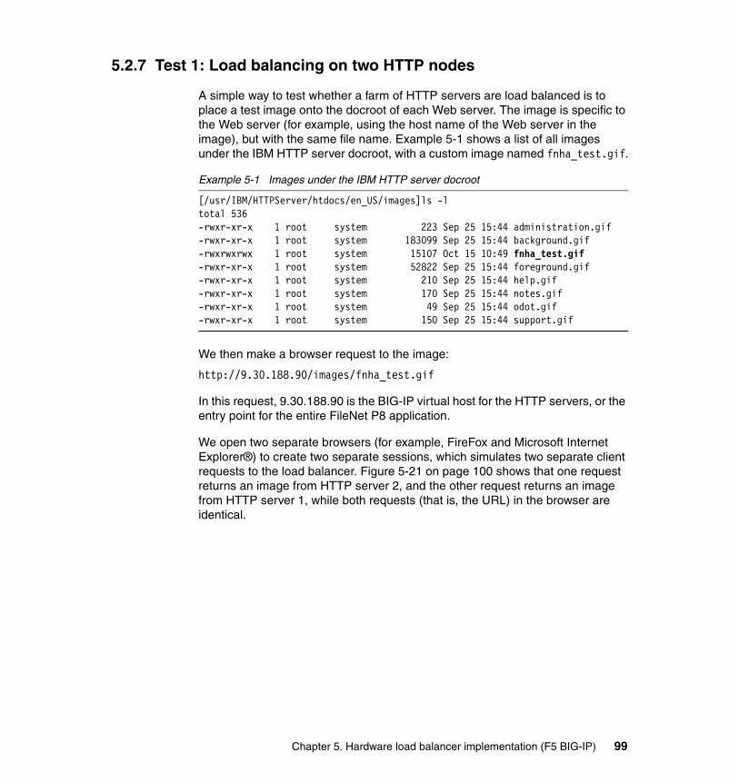
5.2.7 Test 1: Load balancing on two HTTP nodes
A simple way to test whether a farm of HTTP servers are load balanced is to place a test image onto the docroot of each Web server. The image is specific to the Web server (for example, using the host name of the Web server in the image), but with the same file name. Example 5-1 shows a list of all images under the IBM HTTP server docroot, with a custom image named fnha_test.gif.
Example 5-1 Images under the IBM HTTP server docroot
[/usr/IBM/HTTPServer/htdocs/en_US/images]ls -ltotal 536-rwxr-xr-x 1 root system 223 Sep 25 15:44 administration.gif-rwxr-xr-x 1 root system 183099 Sep 25 15:44 background.gif-rwxrwxrwx 1 root system 15107 Oct 15 10:49 fnha_test.gif-rwxr-xr-x 1 root system 52822 Sep 25 15:44 foreground.gif-rwxr-xr-x 1 root system 210 Sep 25 15:44 help.gif-rwxr-xr-x 1 root system 170 Sep 25 15:44 notes.gif-rwxr-xr-x 1 root system 49 Sep 25 15:44 odot.gif-rwxr-xr-x 1 root system 150 Sep 25 15:44 support.gif
We then make a browser request to the image:
http://9.30.188.90/images/fnha_test.gif
In this request, 9.30.188.90 is the BIG-IP virtual host for the HTTP servers, or the entry point for the entire FileNet P8 application.
We open two separate browsers (for example, FireFox and Microsoft Internet Explorer®) to create two separate sessions, which simulates two separate client requests to the load balancer. Figure 5-21 on page 100 shows that one request returns an image from HTTP server 2, and the other request returns an image from HTTP server 1, while both requests (that is, the URL) in the browser are identical.
Chapter 5. Hardware load balancer implementation (F5 BIG-IP) 99
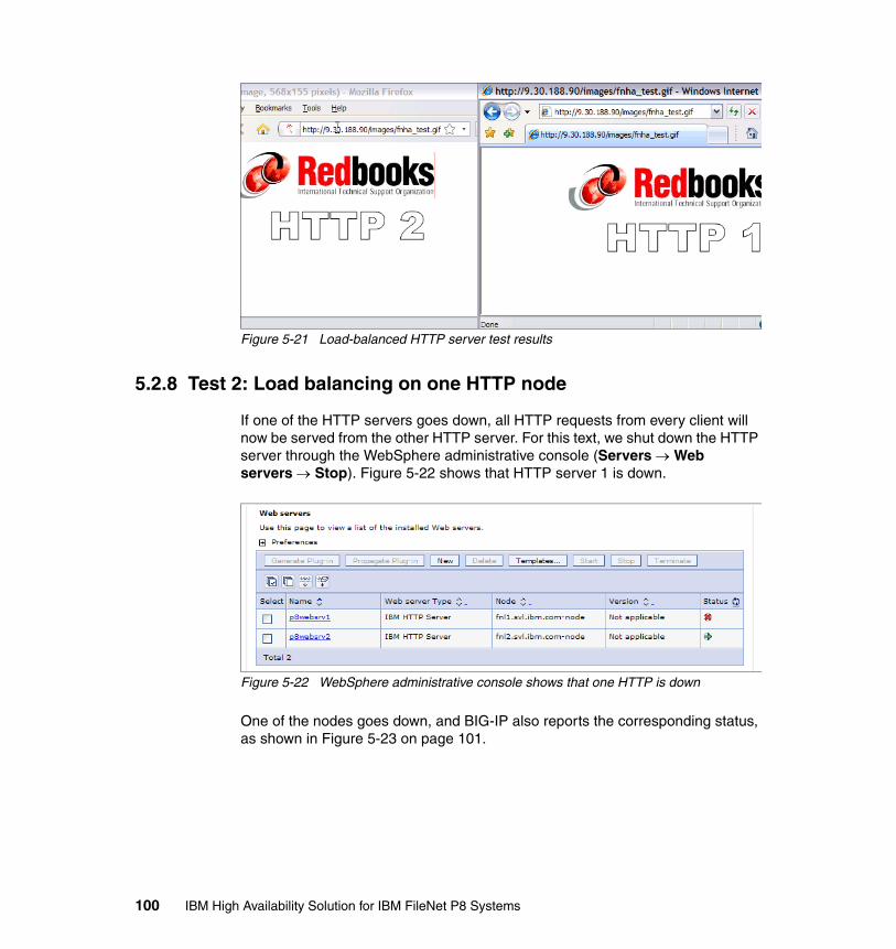
Figure 5-21 Load-balanced HTTP server test results
5.2.8 Test 2: Load balancing on one HTTP node
If one of the HTTP servers goes down, all HTTP requests from every client will now be served from the other HTTP server. For this text, we shut down the HTTP server through the WebSphere administrative console (Servers → Web servers → Stop). Figure 5-22 shows that HTTP server 1 is down.
Figure 5-22 WebSphere administrative console shows that one HTTP is down
One of the nodes goes down, and BIG-IP also reports the corresponding status, as shown in Figure 5-23 on page 101.
100 IBM High Availability Solution for IBM FileNet P8 Systems
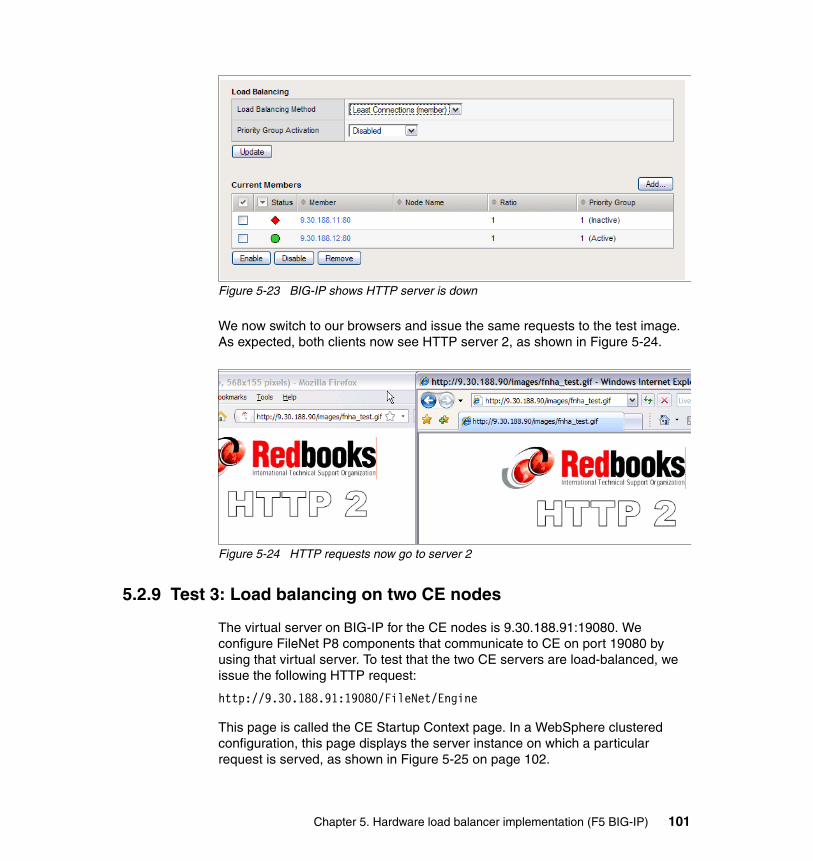
Figure 5-23 BIG-IP shows HTTP server is down
We now switch to our browsers and issue the same requests to the test image. As expected, both clients now see HTTP server 2, as shown in Figure 5-24.
Figure 5-24 HTTP requests now go to server 2
5.2.9 Test 3: Load balancing on two CE nodes
The virtual server on BIG-IP for the CE nodes is 9.30.188.91:19080. We configure FileNet P8 components that communicate to CE on port 19080 by using that virtual server. To test that the two CE servers are load-balanced, we issue the following HTTP request:
http://9.30.188.91:19080/FileNet/Engine
This page is called the CE Startup Context page. In a WebSphere clustered configuration, this page displays the server instance on which a particular request is served, as shown in Figure 5-25 on page 102.
Chapter 5. Hardware load balancer implementation (F5 BIG-IP) 101
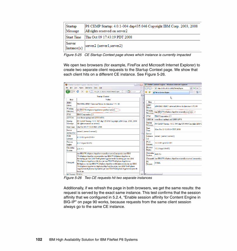
Figure 5-25 CE Startup Context page shows which instance is currently impacted
We open two browsers (for example, FireFox and Microsoft Internet Explorer) to create two separate client requests to the Startup Context page. We show that each client hits on a different CE instance. See Figure 5-26.
Figure 5-26 Two CE requests hit two separate instances
Additionally, if we refresh the page in both browsers, we get the same results: the request is served by the exact same instance. This test confirms that the session affinity that we configured in 5.2.4, “Enable session affinity for Content Engine in BIG-IP” on page 90 works, because requests from the same client session always go to the same CE instance.
102 IBM High Availability Solution for IBM FileNet P8 Systems
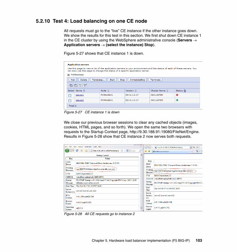
5.2.10 Test 4: Load balancing on one CE node
All requests must go to the “live” CE instance if the other instance goes down. We show the results for this test in this section. We first shut down CE instance 1 in the CE cluster by using the WebSphere administrative console (Servers → Application servers → (select the instance) Stop).
Figure 5-27 shows that CE instance 1 is down.
Figure 5-27 CE instance 1 is down
We close our previous browser sessions to clear any cached objects (images, cookies, HTML pages, and so forth). We open the same two browsers with requests to the Startup Context page, http://9.30.188.91:19080/FileNet/Engine. Results in Figure 5-28 show that CE instance 2 now serves both requests.
Figure 5-28 All CE requests go to instance 2
Chapter 5. Hardware load balancer implementation (F5 BIG-IP) 103
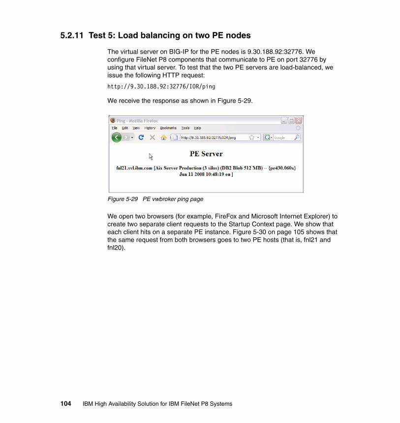
5.2.11 Test 5: Load balancing on two PE nodes
The virtual server on BIG-IP for the PE nodes is 9.30.188.92:32776. We configure FileNet P8 components that communicate to PE on port 32776 by using that virtual server. To test that the two PE servers are load-balanced, we issue the following HTTP request:
http://9.30.188.92:32776/IOR/ping
We receive the response as shown in Figure 5-29.
Figure 5-29 PE vwbroker ping page
We open two browsers (for example, FireFox and Microsoft Internet Explorer) to create two separate client requests to the Startup Context page. We show that each client hits on a separate PE instance. Figure 5-30 on page 105 shows that the same request from both browsers goes to two PE hosts (that is, fnl21 and fnl20).
104 IBM High Availability Solution for IBM FileNet P8 Systems
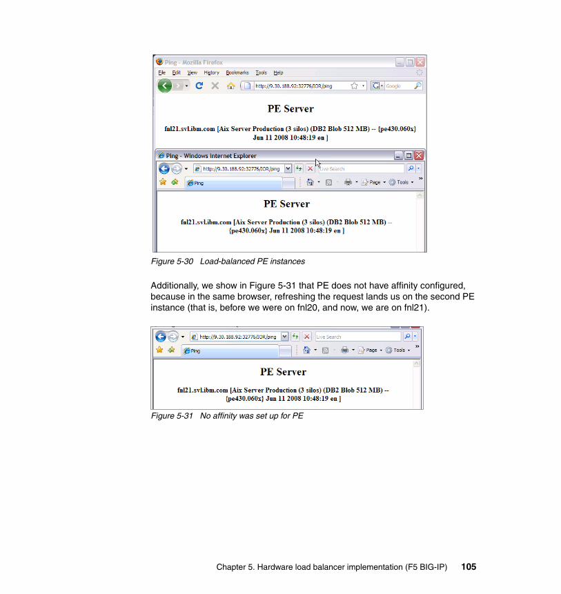
Figure 5-30 Load-balanced PE instances
Additionally, we show in Figure 5-31 that PE does not have affinity configured, because in the same browser, refreshing the request lands us on the second PE instance (that is, before we were on fnl20, and now, we are on fnl21).
Figure 5-31 No affinity was set up for PE
Chapter 5. Hardware load balancer implementation (F5 BIG-IP) 105
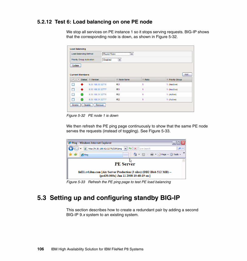
5.2.12 Test 6: Load balancing on one PE node
We stop all services on PE instance 1 so it stops serving requests. BIG-IP shows that the corresponding node is down, as shown in Figure 5-32.
Figure 5-32 PE node 1 is down
We then refresh the PE ping page continuously to show that the same PE node serves the requests (instead of toggling). See Figure 5-33.
Figure 5-33 Refresh the PE ping page to test PE load balancing
5.3 Setting up and configuring standby BIG-IP
This section describes how to create a redundant pair by adding a second BIG-IP 9.x system to an existing system.
106 IBM High Availability Solution for IBM FileNet P8 Systems
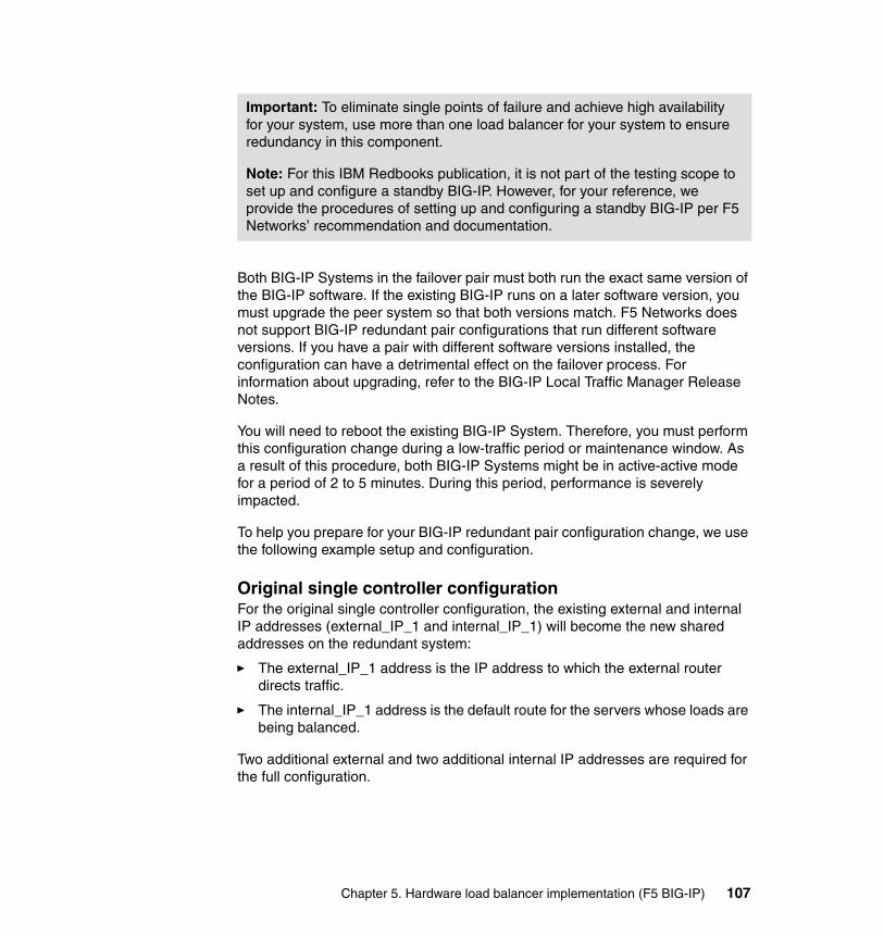
Both BIG-IP Systems in the failover pair must both run the exact same version of the BIG-IP software. If the existing BIG-IP runs on a later software version, you must upgrade the peer system so that both versions match. F5 Networks does not support BIG-IP redundant pair configurations that run different software versions. If you have a pair with different software versions installed, the configuration can have a detrimental effect on the failover process. For information about upgrading, refer to the BIG-IP Local Traffic Manager Release Notes.
You will need to reboot the existing BIG-IP System. Therefore, you must perform this configuration change during a low-traffic period or maintenance window. As a result of this procedure, both BIG-IP Systems might be in active-active mode for a period of 2 to 5 minutes. During this period, performance is severely impacted.
To help you prepare for your BIG-IP redundant pair configuration change, we use the following example setup and configuration.
Original single controller configurationFor the original single controller configuration, the existing external and internal IP addresses (external_IP_1 and internal_IP_1) will become the new shared addresses on the redundant system:
� The external_IP_1 address is the IP address to which the external router directs traffic.
� The internal_IP_1 address is the default route for the servers whose loads are being balanced.
Two additional external and two additional internal IP addresses are required for the full configuration.
Important: To eliminate single points of failure and achieve high availability for your system, use more than one load balancer for your system to ensure redundancy in this component.
Note: For this IBM Redbooks publication, it is not part of the testing scope to set up and configure a standby BIG-IP. However, for your reference, we provide the procedures of setting up and configuring a standby BIG-IP per F5 Networks’ recommendation and documentation.
Chapter 5. Hardware load balancer implementation (F5 BIG-IP) 107

Redundant configurationFor the new redundant controller configuration, external_IP_2 and external_IP_3 are the new primary external interface addresses for each controller, and internal_IP_2 and internal_IP_3 are the new primary internal interfaces. The external_IP_1 and internal_IP_1 addresses are changed to the floating addresses that are shared between the units, which eliminates the need to modify the upstream router or downstream nodes.
These addresses are the specific configuration for the BIG-IP redundant pair:
� BIG-IP 2 configuration (the new BIG-IP that is being added):
– external_IP_2 is the new primary external interface.– internal_IP_2 is the new primary internal interface.– external_IP_1 and internal_IP_1 are the new shared addresses.
� BIG-IP 1 configuration (the original stand-alone BIG-IP):
– external_IP_3 is the new primary external interface.– internal_IP_3 is the new primary internal interface.– external_IP_1 and internal_IP_1 are the new shared addresses.
Setup and configuration summaryFor our example, follow this procedure to set up and configure a redundant pair:
1. Configuring the new BIG-IP in a redundant pair
2. Configuring the original BIG-IP as a standby system
3. Synchronizing configurations
5.3.1 Configuring the new BIG-IP in a redundant pair
To configure the new BIG-IP System in a redundant pair, perform the following procedure:
1. Connect the new BIG-IP System with a failover cable to the existing BIG-IP System, and turn on the power.
2. Connect a console to the new BIG-IP System. When the system is powered up, type the following command:
config
Important: Do not connect the network cabling to the new BIG-IP System, because connecting the cabling can cause a network disturbance after the system reboots.
108 IBM High Availability Solution for IBM FileNet P8 Systems
3. Follow the steps to configure the management IP address, subnet mask, and default gateway.
4. Log in to the Configuration utility using the management address. The Setup utility runs. Install the license.
If the BIG-IP System contains a previous configuration, you can run the Setup utility by clicking Overview → Welcome → Run the Setup Utility.
5. Set up the basic network configuration:
a. Enter the host name in the Host Name field.
b. From the High Availability drop-down menu, select Redundant Pair.
c. From the Unit ID drop-down menu, select 1.
d. Finish defining the General Properties and User Administration information.
e. Click Next.
6. Under the Basic Network Configuration window, click Next. The Internal Network Configuration window displays.
7. Set up the internal network configuration:
a. For the Floating IP, enter the existing BIG-IP System’s internal address as the new internal Floating IP address (in our example, internal_IP_1).
b. For the Failover IP, enter the new internal primary address of the peer unit in the redundant system (in our example, internal_IP_3).
c. Finish defining the Internal Network and VLAN configuration.
d. Click Next. The External Network Configuration window appears.
8. Set up the external network configuration:
– Enter the appropriate addresses for the Floating IP and Failover IP. For our example, the new internal Floating IP is external_IP_1, and the Failover IP is external_IP_3.
Important: The administrator user name and password must be the same as the existing system. If the user name and password are not set correctly, the configurations will not be synchronized.
Important: Do not use the IP address that the existing system currently uses, because that address will be the shared and floating address for the redundant pair. Additionally, the VLAN must be on the new BIG-IP System. The name is case sensitive.
Chapter 5. Hardware load balancer implementation (F5 BIG-IP) 109
9. Complete the Setup utility.
10.Reboot the new BIG-IP System.
After the reboot, the BIG-IP System will be the standby controller in a redundant pair configuration (provided that the failover cable was connected).
Verifying and reviewing the configurationTo verify the state of the BIG-IP System, type the following command:
bigpipe fo
If the new BIG-IP System is in active mode, check to see if the failover cable is securely connected to the failover port.
You can review the base IP configuration by typing the following command:
bigpipe base list
5.3.2 Configuring the original BIG-IP as a standby system
To configure the original BIG-IP System as the redundant standby system, perform the following procedure:
1. Log in to the Configuration utility.
2. Select System → Platform.
3. From the High Availability drop-down menu, select Redundant Pair.
4. From the Unit ID drop-down menu, select 2, and click Update.
5. Select Network → Self IPs.
6. Edit the existing IPs, external_IP_1 and internal_IP_1, and select the Floating IP check box for each self IP.
7. Create two new self IP addresses, where external_IP_3 is the new primary external interface, and internal_IP_3 is the new primary internal interface.
8. Reboot the BIG-IP System.
Note: The failover port resembles the serial port. Both ports are labeled. The failover cable has custom pinouts, as documented in SOL1426: Failover cable pinouts for the BIG-IP and 3-DNS Controllers.
Important: Rebooting the BIG-IP System results in a temporary site outage.
110 IBM High Availability Solution for IBM FileNet P8 Systems
After you reboot, the BIG-IP System will be in a redundant pair configuration in standby mode (provided the failover cable was connected), because the new BIG-IP System is in active mode.
To fail back to the original BIG-IP and start traffic flowing, type the following command on the new BIG-IP System:
bigpipe fo standby
5.3.3 Synchronizing configurations
To synchronize the configuration between the standby system and the active system, perform the following procedure:
1. The existing BIG-IP must now be in active mode, and the new BIG-IP must be in standby mode. Verify this situation by typing the following command on each system:
bigpipe fo
2. After you confirm the state of the BIG-IP Systems, connect the new BIG-IP System to the network.
3. Synchronize the configuration by typing the following command:
bigpipe config sync all
4. Confirm that the new BIG-IP System has the correct configuration by typing the following command:
bigpipe list
5. Verify that the /config/bigip.conf file is the same size on both systems.
At this point, both units have the same configuration and will failover seamlessly. F5 Networks recommends that you test the configuration synchronization and failover in both directions during the maintenance window.
5.3.4 Viewing redundancy states and synchronization status
You can globally view the current redundancy state of a unit by viewing the upper-left corner of any Configuration utility window. You can also view synchronization status in this same portion of each window, but only if you have
Important: The new BIG-IP System must be in standby mode before you connect it to the network; otherwise, it might respond to Address Resolution Protocol (ARP) requests for the floating addresses, interfering with traffic currently flowing through the active system.
Chapter 5. Hardware load balancer implementation (F5 BIG-IP) 111
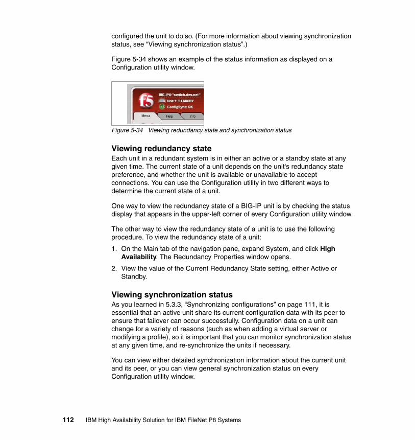
configured the unit to do so. (For more information about viewing synchronization status, see “Viewing synchronization status”.)
Figure 5-34 shows an example of the status information as displayed on a Configuration utility window.
Figure 5-34 Viewing redundancy state and synchronization status
Viewing redundancy state Each unit in a redundant system is in either an active or a standby state at any given time. The current state of a unit depends on the unit's redundancy state preference, and whether the unit is available or unavailable to accept connections. You can use the Configuration utility in two different ways to determine the current state of a unit.
One way to view the redundancy state of a BIG-IP unit is by checking the status display that appears in the upper-left corner of every Configuration utility window.
The other way to view the redundancy state of a unit is to use the following procedure. To view the redundancy state of a unit:
1. On the Main tab of the navigation pane, expand System, and click High Availability. The Redundancy Properties window opens.
2. View the value of the Current Redundancy State setting, either Active or Standby.
Viewing synchronization status As you learned in 5.3.3, “Synchronizing configurations” on page 111, it is essential that an active unit share its current configuration data with its peer to ensure that failover can occur successfully. Configuration data on a unit can change for a variety of reasons (such as when adding a virtual server or modifying a profile), so it is important that you can monitor synchronization status at any given time, and re-synchronize the units if necessary.
You can view either detailed synchronization information about the current unit and its peer, or you can view general synchronization status on every Configuration utility window.
112 IBM High Availability Solution for IBM FileNet P8 Systems
Viewing detailed synchronization statusYou can view detailed configuration synchronization status, such as the internal static self IP addresses that the two units use when synchronizing data, by displaying the ConfigSync window of the Configuration utility. This window is available from the Redundancy Properties window.
Table 5-4 lists and describes the status-related settings that the ConfigSync window displays.
Table 5-4 Status information on the ConfigSync window
For additional information, refer to support.f5.com:
https://support.f5.com/kb/en-us/products/big-ip_ltm/manuals/product/bigip9_0sys/9_0_xSystemMgmtGuide-13-1.html
5.3.5 Validate standby BIG-IP failover
After you set up and configure the standby BIG-IP, you need to validate the active BIG-IP failing over or being manually failed over to the standby. Manual failover can be used for upgrading BIG-IP software versions or for other BIG-IP maintenance. Table 5-5 on page 114 summarizes the test methods for both manual and disaster failover to validate the setup.
Status setting Description
ConfigSync Peer Displays the internal static self IP address that the BIG-IP System uses to determine the peer unit for synchronization.
Status message Displays the state of the peer, that is, active or standby. May also report the status as unknown if connectivity problems exist.
Last Change (Self) Displays the day, date, and exact time that the configuration date of the unit you are configuring was last changed.
Last Change (Peer) Displays the day, date, and exact time that the configuration data of the peer unit was last changed.
Last ConfigSync Displays the day, date, and exact time that a user synchronized the configuration data between the two units.
Chapter 5. Hardware load balancer implementation (F5 BIG-IP) 113
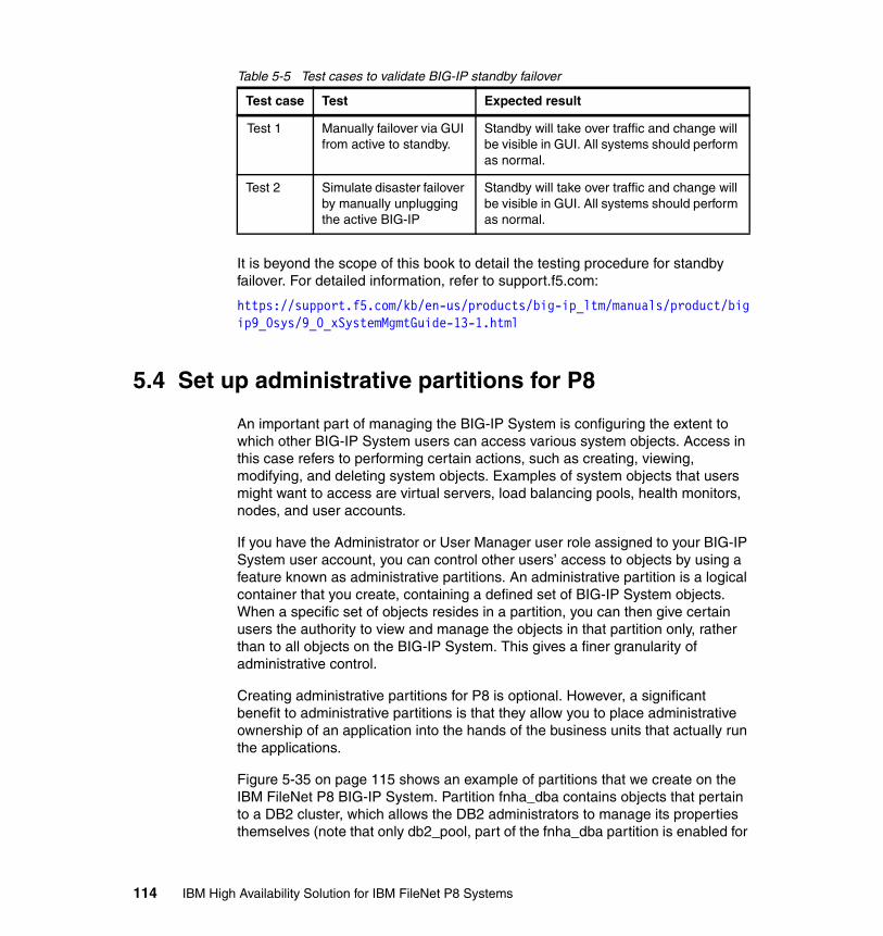
Table 5-5 Test cases to validate BIG-IP standby failover
It is beyond the scope of this book to detail the testing procedure for standby failover. For detailed information, refer to support.f5.com:
https://support.f5.com/kb/en-us/products/big-ip_ltm/manuals/product/bigip9_0sys/9_0_xSystemMgmtGuide-13-1.html
5.4 Set up administrative partitions for P8
An important part of managing the BIG-IP System is configuring the extent to which other BIG-IP System users can access various system objects. Access in this case refers to performing certain actions, such as creating, viewing, modifying, and deleting system objects. Examples of system objects that users might want to access are virtual servers, load balancing pools, health monitors, nodes, and user accounts.
If you have the Administrator or User Manager user role assigned to your BIG-IP System user account, you can control other users’ access to objects by using a feature known as administrative partitions. An administrative partition is a logical container that you create, containing a defined set of BIG-IP System objects. When a specific set of objects resides in a partition, you can then give certain users the authority to view and manage the objects in that partition only, rather than to all objects on the BIG-IP System. This gives a finer granularity of administrative control.
Creating administrative partitions for P8 is optional. However, a significant benefit to administrative partitions is that they allow you to place administrative ownership of an application into the hands of the business units that actually run the applications.
Figure 5-35 on page 115 shows an example of partitions that we create on the IBM FileNet P8 BIG-IP System. Partition fnha_dba contains objects that pertain to a DB2 cluster, which allows the DB2 administrators to manage its properties themselves (note that only db2_pool, part of the fnha_dba partition is enabled for
Test case Test Expected result
Test 1 Manually failover via GUI from active to standby.
Standby will take over traffic and change will be visible in GUI. All systems should perform as normal.
Test 2 Simulate disaster failover by manually unplugging the active BIG-IP
Standby will take over traffic and change will be visible in GUI. All systems should perform as normal.
114 IBM High Availability Solution for IBM FileNet P8 Systems
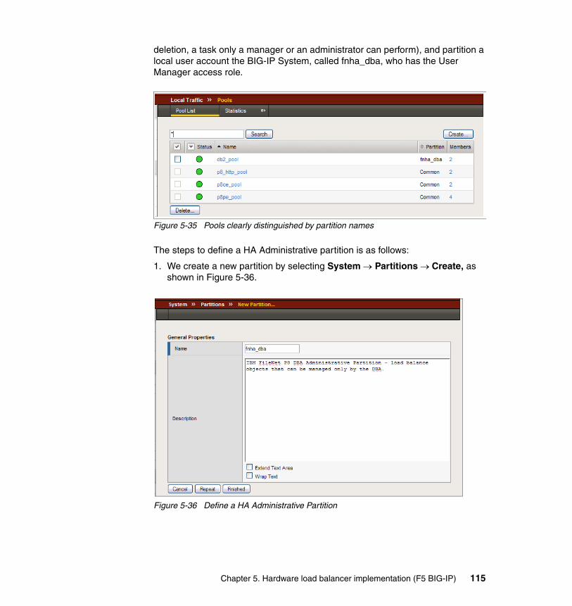
deletion, a task only a manager or an administrator can perform), and partition a local user account the BIG-IP System, called fnha_dba, who has the User Manager access role.
Figure 5-35 Pools clearly distinguished by partition names
The steps to define a HA Administrative partition is as follows:
1. We create a new partition by selecting System → Partitions → Create, as shown in Figure 5-36.
Figure 5-36 Define a HA Administrative Partition
Chapter 5. Hardware load balancer implementation (F5 BIG-IP) 115
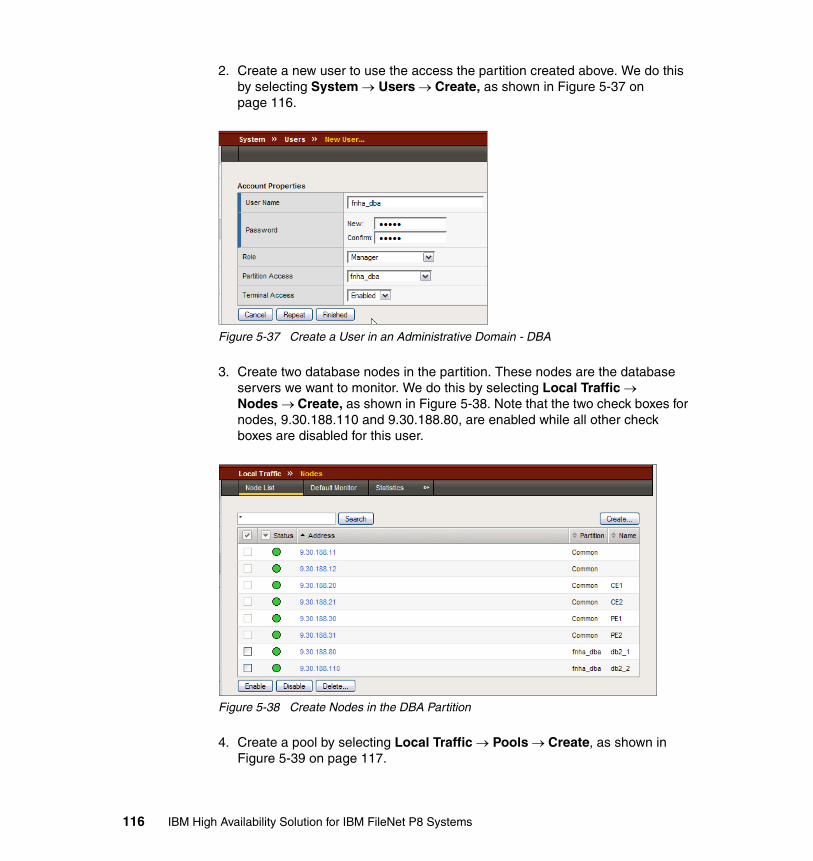
2. Create a new user to use the access the partition created above. We do this by selecting System → Users → Create, as shown in Figure 5-37 on page 116.
Figure 5-37 Create a User in an Administrative Domain - DBA
3. Create two database nodes in the partition. These nodes are the database servers we want to monitor. We do this by selecting Local Traffic → Nodes → Create, as shown in Figure 5-38. Note that the two check boxes for nodes, 9.30.188.110 and 9.30.188.80, are enabled while all other check boxes are disabled for this user.
Figure 5-38 Create Nodes in the DBA Partition
4. Create a pool by selecting Local Traffic → Pools → Create, as shown in Figure 5-39 on page 117.
116 IBM High Availability Solution for IBM FileNet P8 Systems
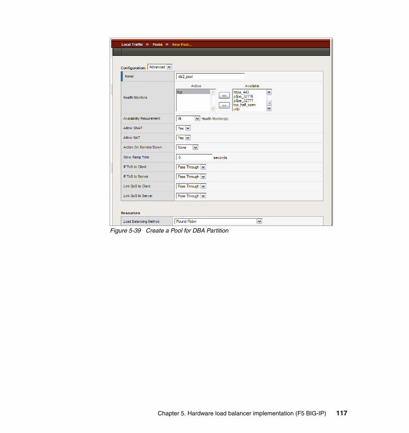
Figure 5-39 Create a Pool for DBA Partition
Chapter 5. Hardware load balancer implementation (F5 BIG-IP) 117

118 IBM High Availability Solution for IBM FileNet P8 Systems
Chapter 6. Web tier implementation
This chapter describes the Web tier setup for a highly available FileNet P8 environment.
We discuss the following topics:
� Introduction� Hardware components� Software components� Failover test at the Web tier level� Maintenance recommendations
6
© Copyright IBM Corp. 2009. All rights reserved. 119
6.1 Introduction
FileNet P8 provides Web interfaces that allow users to access and manage content and processes in FileNet P8 systems. Workplace, as part of FileNet P8 Application Engine (AE), is an easy-to-use Web application that enables users to interact with the FileNet P8 system.
The Web interfaces offer the following key features:
� Secure access to content management: By offering Lightweight Directory Access Protocol (LDAP) authentication into the P8 systems.
� Wizard-driven content contribution: Eliminates entry errors (add or check-in) and ensures accuracy with intuitive, easy-to-use content entry templates.
� Document review and approval workflow: Streamlines approval processes and expedites Web content publishing through preconfigured process templates that provide a common procedure for content approval and publishing. Actively maintains audit trails to comply with regulatory mandates and corporate governance standards.
� Comprehensive page and document management: Manages all types of unstructured content (including paper documents, HTML, XML, rich media, PDF, and e-mail) and complex content.
� Customized features: Based on user preferences, such as search templates, paging, appearance, behavior, and security.
FileNet P8 Web interfaces can run within a WebSphere application server. We recommend that you deploy the HTTP servers outside of a application server. Decoupling the Web tier from the WebSphere application server layer allows for better server manageability (for example, the HTTP servers can be located in their own security zone, or DMZ) and for easier horizontal scalability (for example, just add HTTP servers as needed).
We use a Web server farm for our high availability configuration. Web server farms provided through hardware or software load-balancing technology enable high availability at the Web server tier. A farm is a set of load-balanced servers that are clones of each other, each actively providing the same service, with the same applications and same binding to servers in the tiers beneath them. Farms are best practice for server tiers that are relatively static in terms of content, which makes it easy to maintain the servers as clones of each other.
The FileNet P8 Web-based components have been certified to operate within Web and application server farms, such as IBM WebSphere clusters. These types of farms provide for server redundancy with the added value of scalability, because all of the servers in the farm are active. Application server farms can be
120 IBM High Availability Solution for IBM FileNet P8 Systems
combined with hardware-based load-balancing solutions, such as F5 Networks BIG-IP load balancer or software-based solutions, such as IBM Load Balancer, which is part of WebSphere Edge Components.
A load-balanced Web server farm provides both better availability and better scalability than a single Web server. When a Web server fails, the load balancer automatically detects the failure and redirects user requests to another server in the farm, thereby keeping the service available. Administrators can increase Web site performance and capacity by simply adding servers to the farm.
6.2 Hardware components
In our case study, we assume P8 system is accessed only by AE Workplace Web applications from browsers which, in general, can be anywhere in the world.
We assume the firewalls, Domain Name System (DNS), and LDAP server components are already highly available. We therefore do not repeat their configuration in this book.
We use the following P8 Web tier hardware components:
� Two load balancers� Two HTTP server nodes
Figure 6-1 on page 122 illustrates the Web tier components and their placement in a DMZ.
Chapter 6. Web tier implementation 121
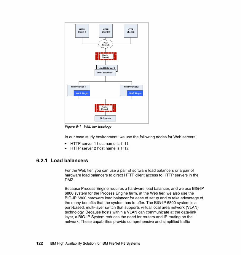
Figure 6-1 Web tier topology
In our case study environment, we use the following nodes for Web servers:
� HTTP server 1 host name is fnl1.� HTTP server 2 host name is fnl2.
6.2.1 Load balancers
For the Web tier, you can use a pair of software load balancers or a pair of hardware load balancers to direct HTTP client access to HTTP servers in the DMZ.
Because Process Engine requires a hardware load balancer, and we use BIG-IP 6800 system for the Process Engine farm, at the Web tier, we also use the BIG-IP 6800 hardware load balancer for ease of setup and to take advantage of the many benefits that the system has to offer. The BIG-IP 6800 system is a port-based, multi-layer switch that supports virtual local area network (VLAN) technology. Because hosts within a VLAN can communicate at the data-link layer, a BIG-IP System reduces the need for routers and IP routing on the network. These capabilities provide comprehensive and simplified traffic
122 IBM High Availability Solution for IBM FileNet P8 Systems
management and security for FileNet P8 components, such as the Web servers, Content Engine servers, and Process Engine servers.
Chapter 5, “Hardware load balancer implementation (F5 BIG-IP)” on page 73 provides extensive coverage of the BIG-IP hardware load balancer. Refer to that chapter for its features and capabilities, setup, and configuration.
6.3 Software components
The Web tier consists of the following software components:
� IBM HTTP Server Version 6.1.0.17 � Web server plug-ins for IBM WebSphere Application Server Version 6.1.0.17
As illustrated in Figure 6-1 on page 122, we use the F5 BIG-IP as the hardware load balancer for the HTTP servers, and the HTTP servers serve as the load balancer for AE using Web server plug-ins.
6.3.1 IBM HTTP Server system requirements
The IBM HTTP Server software is available along with IBM WebSphere Application Server (although we install it on a separate host for our case study).
To support the basic installation of IBM HTTP Server, the minimum operating system and hardware requirements for the application server must be met on the Web server system. You can find the latest prerequisites at:
http://www.ibm.com/support/docview.wss?rs=180&uid=swg27006921
6.3.2 HTTP server and plug-in setup and management overview
For our case study, the IBM HTTP Servers and the WebSphere Application Server Network Deployment that manage the IBM HTTP Servers run on separate machines.
We assume that WebSphere Application Server Network Deployment is already installed and configured on the FileNet P8 Application Engine nodes, and IBM HTTP Server has to be installed on two machines, fnl1 and fnl2, in DMZ. We describe the installation process performed on fnl1. The installation procedure for fnl2 is the same.
Web servers are defined to the WebSphere Application Server. A Web server can reside on a managed or unmanaged node. If located on a managed node in a distributed server environment, a node agent is installed on the Web server
Chapter 6. Web tier implementation 123
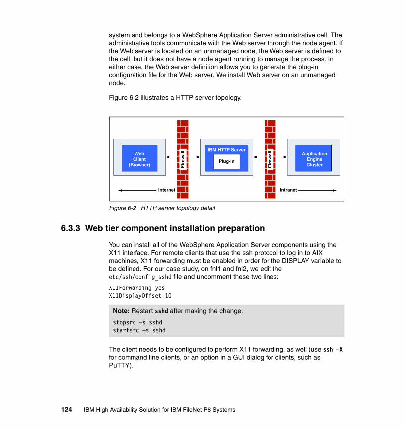
system and belongs to a WebSphere Application Server administrative cell. The administrative tools communicate with the Web server through the node agent. If the Web server is located on an unmanaged node, the Web server is defined to the cell, but it does not have a node agent running to manage the process. In either case, the Web server definition allows you to generate the plug-in configuration file for the Web server. We install Web server on an unmanaged node.
Figure 6-2 illustrates a HTTP server topology.
Figure 6-2 HTTP server topology detail
6.3.3 Web tier component installation preparation
You can install all of the WebSphere Application Server components using the X11 interface. For remote clients that use the ssh protocol to log in to AIX machines, X11 forwarding must be enabled in order for the DISPLAY variable to be defined. For our case study, on fnl1 and fnl2, we edit the etc/ssh/config_sshd file and uncomment these two lines:
X11Forwarding yesX11DisplayOffset 10
The client needs to be configured to perform X11 forwarding, as well (use ssh –X for command line clients, or an option in a GUI dialog for clients, such as PuTTY).
Note: Restart sshd after making the change:
stopsrc –s sshdstartsrc –s sshd
124 IBM High Availability Solution for IBM FileNet P8 Systems
IBM HTTP Server and WebSphere plug-in packageIBM HTTP Server V6 is bundled with WebSphere Application Server V6. The administrative functionality is integrated into WebSphere Application Server to provide remote administration through the administrative console. This enhanced administrative function is only available for the IBM HTTP Server.
The IBM HTTP Server installation package is delivered as a CD or downloaded as a tar file image.
We use the image file C88TMML.tar.gz (WebSphere Application Server Network Deployment V6.1 Supplements for AIX 5L V5, 64-bit Support, Application Client, HTTP Server, Web Server Plug-ins, Installation Factory, Migration Tool, IBM Support Assistant and Update Installer, Multilingual).
The C88TMML.tar.gz file is approximately 390 MB. We place it in a temporary file system.
Before starting the installation, we log in as root and issue the following commands to untar the file from our temporary file system (for our case study, we use /fnsw, although you will probably put the C88TMML.tar.gz file in a special temporary directory):
# gunzip C88TMML.tar.gz# mkdir C88TMML# cd C88TMML# tar -xvf ../C88TMML.tar
Fix Pack 17 installation packageWe download Fix Pack 17 (6.1.0-WS-IHS-AixPPC64-FP0000017.pak file in our case) to the directory /fnsw and untar it in the directory /fnsw/FP17.
Fix Pack 17 contains the fix pack installation utility called UpdateInstaller. This utility is also included in WebSphere Application Server Network Deployment V6.1 Supplements. Use the UpdateInstaller utility that comes with the fix pack to install the fix pack.
On the download page for the fix pack, the Installation Instructions section has a link to the appropriate version of UpdateInstaller. We download the UpdateInstaller file (download.updii.61017.aix.ppc64.zip for our case study) to the /fnsw directory, unzip it under /fnsw/fp17 directory, and install UpdateInstaller:
1. Log in as root on fnl1.
Chapter 6. Web tier implementation 125
2. Issue the following commands:
# cd /fnsw/fp17/UpdateInstaller# ./install
The default installation directory is /usr/IBM/WebSphere/UpdateInstaller. We use the default.
6.3.4 IBM HTTP Server installation steps
To start the installation wizard, log in as root and issue the commands:
# cd /fnsw/C88TMML/IHS# ./install
Follow the wizard to install IBM HTTP Server on an unmanaged node running IBM HTTP Server administration server:
1. Enter the installation location. The default is /usr/IBM/HTTPServer.
2. Enter the port value assignment for the HTTP daemon and for the HTTP administration server daemon. The defaults are 80 for the HTTP daemon and 8008 for the administration server.
3. Enter the HTTP administrator user and password. Select the checkbox for user creation if you need to create a user.
4. Enter administrator user and group to set up HTTP server administration. Select the checkbox for user/group creation if you need to create them.
5. Choose to install the HTTP server plug-in. Enter the Web server name and application server deployment management name.
6. Review the installation parameters in the installation summary window (Figure 6-3 on page 127), and click Next to begin the installation.
126 IBM High Availability Solution for IBM FileNet P8 Systems

Figure 6-3 Installation summary window
6.3.5 Web server plug-ins installation steps
Web server plug-ins for IBM WebSphere Application Server are packaged in the same file with IBM HTTP Server. To start the installation wizard, issue these AIX commands:
# cd /fnsw/C88TMML/plugin# ./install
The Web server plug-in installation provides a wizard that takes you through the installation process. The wizard defines and installs the plug-in, configures the Web server, and defines the Web server to WebSphere.
The wizard also creates a script file that you can copy to WebSphere Application Server Network Deployment server to run against the WebSphere Application Server Network Deployment server to define the Web server for the deployment manager.
Follow these steps to install the plug-in:
1. Select IBM HTTP Server V6 or IBM HTTP Server V6.1.
2. Select Remote installation.
Enter an installation directory. By default, the location is /usr/IBM/HTTPServer/Plugins. We use the default. We use <plugin_home> to refer to the plug-in installation location on the following steps.
Chapter 6. Web tier implementation 127
3. Enter the Web server configuration file and port. By default, the configuration file is /usr/IBM/HTTPServer/conf/httpd.conf, and port 80 is used. We use the default settings.
4. Enter a name for the Web server definition. We use p8websrv1, which is the <Web_server_home> directory.
5. Select the location for the plug-in configuration file. By default, the location is under the directory config in the plug-in installation directory (<plugin_home>/config/<Web_server_name>/plugin-cfg.xml). We use the default file name.
6. Enter the application server host name. We use fnl3.
7. Check the summary installation parameter window and start the installation if the parameters are correct. The installation performs the following tasks:
a. Creates a temporary plug-in configuration file and places it in the specified location.
b. Updates the Web server configuration file with the plug-in configuration, including the location of the plug-in configuration file.
c. Generates a script to define the Web server and an unmanaged node to WebSphere Application Server. The script is located in <plug-in_home>/bin/configure<Web_server_name>.
8. At the end of the installation, start the HTTP administrator by using the command adminctl start from the /usr/IBM/HTTPServer/bin directory.
9. Copy the script to the <was_home>/bin directory of the deployment manager machine. Start the deployment manager and execute the script.
10.Run both the IBM HTTP Server and WebSphere Application Server plug-in installations on fnl2, and run the generated script in the deployment manager machine.
11.From AE, go to the WebSphere Application Server Network Deployment Web Server administrator panel (Servers → Web Servers) to propagate the HTTP Server plug-in from the WebSphere Application Server Network Deployment administrator console. Click Propagate Plug-in from the Web servers administrative panel. See Figure 6-4 on page 129.
128 IBM High Availability Solution for IBM FileNet P8 Systems

Figure 6-4 WebSphere Application Server Network Deployment Web servers administrative panel
6.3.6 Fix Pack 17 installation steps
Perform these steps to install Fix Pack 17:
1. At the end of the HTTP server configuration, stop both Web servers from the AE administration console, and then, stop the IBM HTTP Server administration server on fnl1 and fnl2 by issuing the commands:
# cd /usr/IBM/HTTPServer/bin# adminctl stop
2. On both fn11 and fn12, install WebSphere Application Server Network Deployment Fix Pack 17 by issuing these commands:
# cd /usr/IBM/WebSphere/UpdateInstaller# ./update.sh
3. To update WebSphere Application Server Network Deployment to Fix Pack 17, enter the /fnsw/FP17 directory to be the directory containing fix pack packages in the installation wizard panel.
4. Restart the IBM HTTP Server administrative server on both Web server machines.
5. Restart the Web server from the AE Web server administrative console.
For more information about IBM HTTP Server installation and management, see Chapter 8 of WebSphere Application Server V6 System Management & Configuration Handbook, SG24-6451.
Chapter 6. Web tier implementation 129
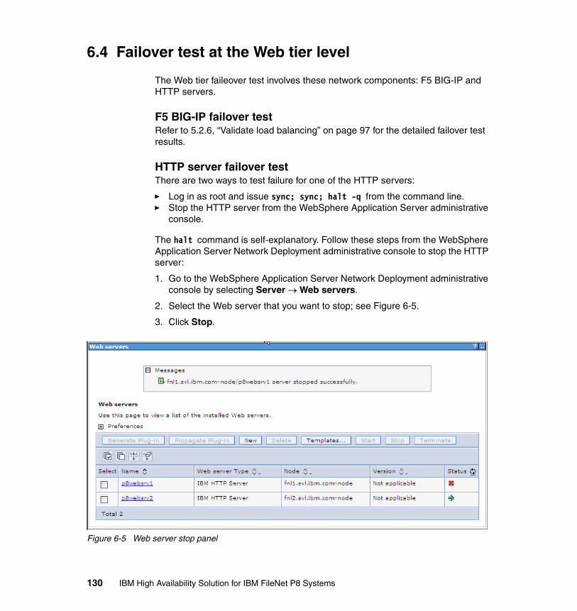
6.4 Failover test at the Web tier level
The Web tier faileover test involves these network components: F5 BIG-IP and HTTP servers.
F5 BIG-IP failover testRefer to 5.2.6, “Validate load balancing” on page 97 for the detailed failover test results.
HTTP server failover testThere are two ways to test failure for one of the HTTP servers:
� Log in as root and issue sync; sync; halt -q from the command line.� Stop the HTTP server from the WebSphere Application Server administrative
console.
The halt command is self-explanatory. Follow these steps from the WebSphere Application Server Network Deployment administrative console to stop the HTTP server:
1. Go to the WebSphere Application Server Network Deployment administrative console by selecting Server → Web servers.
2. Select the Web server that you want to stop; see Figure 6-5.
3. Click Stop.
Figure 6-5 Web server stop panel
130 IBM High Availability Solution for IBM FileNet P8 Systems
Regardless the way that is used to simulate a node failure, the following steps show the procedure to test the HTTP server down event:
1. Start the P8 system. Verify that from a browser, you can log into the AE Workplace Web application. (This step applies to log in only. At this point, you cannot actually perform tasks in Workplace, because the other components are not installed yet.)
2. Simulate the failure for the first HTTP server.
3. Verify that a user can perform all the activities from a Web browser.
4. Restart the closed or halted HTTP server.
5. Simulate the failure for the second HTTP server.
6. Verify that a user can perform all the activities from Web browsers.
7. Restart the closed or halted HTTP server.
6.5 Maintenance recommendations
For maintenance, we recommend that you keep the software level of the HTTP Server and Web server plug-ins for IBM WebSphere Application Server the same as the software level of the WebSphere Application Server Network Deployment administration server.
Chapter 6. Web tier implementation 131

132 IBM High Availability Solution for IBM FileNet P8 Systems
Chapter 7. Application Engine implementation
This chapter describes the high availability options for Application Engine and our case study setup in relation to Application Engine. We also describe the practical, step-by-step procedures that we use to implement high availability for Application Engine.
We discuss the following topics:
� Introduction� High availability options for Application Engine� Design for the case study� Setup for active/active Application Engine cluster (farm)� High availability tests at the Application Engine level
7
© Copyright IBM Corp. 2009. All rights reserved. 133
7.1 Introduction
Application Engine (AE) is the presentation layer for the IBM FileNet P8 core components: Process Engine (PE) and Content Engine (CE). Application Engine hosts the Workplace or WorkplaceXT Web application, Workplace Java applets, and custom Web applications. It is critical that you provide high availability for Application Engine in the overall high availability of the IBM FileNet P8 solution.
For an overview of Application Engine and its components, refer to 2.4, “Application Engine” on page 29.
7.2 High availability options for Application Engine
Application Engine must be highly available. If Application Engine fails, even if Content Engine and Process Engine are still functional, users cannot access the content or the workflow process within the IBM FileNet P8 solution. Application Engine failure results in disruption to normal business operations.
Application Engine runs within a Java 2 Platform, Enterprise Edition (J2EE) application server. You can exploit all the scalability and high availability options that are available for a J2EE application server.
High availability optionsThe following options are available to make Application Engine highly available:
� Active/active cluster
In an active/active cluster (farm) configuration, two or more application server instances are configured to share the same application’s workload. These application server instances can reside on the same physical machine or separate machines. You can front end the active/active cluster by using a hardware load balancer and redirect the traffic over to any active instance. In an active/active cluster with more than one instance available, the load sharing is more effective and the hardware cost is more justifiable.
� Active/passive cluster
In an active/passive cluster, only one instance of the application server is running. The specific node that hosts the application load in an active/passive cluster is called the active node. The secondary node that can potentially host the application load is called the passive node. In an active/passive cluster at any point in time, there is only one node that is active to cater to the application load.
134 IBM High Availability Solution for IBM FileNet P8 Systems
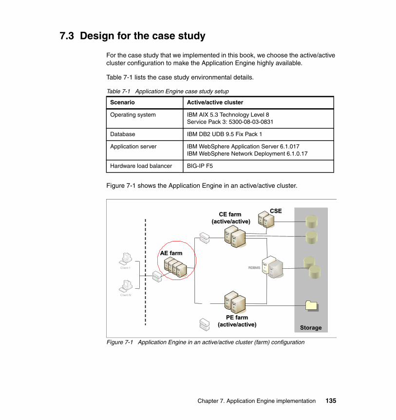
7.3 Design for the case study
For the case study that we implemented in this book, we choose the active/active cluster configuration to make the Application Engine highly available.
Table 7-1 lists the case study environmental details.
Table 7-1 Application Engine case study setup
Figure 7-1 shows the Application Engine in an active/active cluster.
Figure 7-1 Application Engine in an active/active cluster (farm) configuration
Scenario Active/active cluster
Operating system IBM AIX 5.3 Technology Level 8Service Pack 3: 5300-08-03-0831
Database IBM DB2 UDB 9.5 Fix Pack 1
Application server IBM WebSphere Application Server 6.1.017IBM WebSphere Network Deployment 6.1.0.17
Hardware load balancer BIG-IP F5
CE farm (active/active)
CE farm (active/active)
Client 1
Client N
StorageStorage
RDBMSRDBMS
PE farm(active/active)
PE farm(active/active)
CSECSE
AE farmAE farm
Chapter 7. Application Engine implementation 135
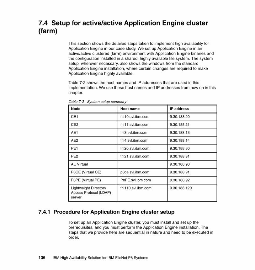
7.4 Setup for active/active Application Engine cluster (farm)
This section shows the detailed steps taken to implement high availability for Application Engine in our case study. We set up Application Engine in an active/active clustered (farm) environment with Application Engine binaries and the configuration installed in a shared, highly available file system. The system setup, wherever necessary, also shows the windows from the standard Application Engine installation, where certain changes are required to make Application Engine highly available.
Table 7-2 shows the host names and IP addresses that are used in this implementation. We use these host names and IP addresses from now on in this chapter.
Table 7-2 System setup summary
7.4.1 Procedure for Application Engine cluster setup
To set up an Application Engine cluster, you must install and set up the prerequisites, and you must perform the Application Engine installation. The steps that we provide here are sequential in nature and need to be executed in order.
Node Host name IP address
CE1 fnl10.svl.ibm.com 9.30.188.20
CE2 fnl11.svl.ibm.com 9.30.188.21
AE1 fnl3.svl.ibm.com 9.30.188.13
AE2 fnl4.svl.ibm.com 9.30.188.14
PE1 fnl20.svl.ibm.com 9.30.188.30
PE2 fnl21.svl.ibm.com 9.30.188.31
AE Virtual 9.30.188.90
P8CE (Virtual CE) p8ce.svl.ibm.com 9.30.188.91
P8PE (Virtual PE) P8PE.svl.ibm.com 9.30.188.92
Lightweight Directory Access Protocol (LDAP) server
fnl110.svl.ibm.com 9.30.188.120
136 IBM High Availability Solution for IBM FileNet P8 Systems
Installing and setting up the prerequisitesInstalling and setting up the prerequisites include the installation of the WebSphere Application Server Network Deployment software, the configuration of the WebSphere Application Server Network Deployment environment, and the setup of the Application Engine cluster.
For our case study, we perform the following steps to install and create the active/active Application Engine cluster:
1. Install WebSphere Application Server Network Deployment 6.1.0.17 on AE1.
WebSphere Application Server Network Deployment only needs to be installed on one of the nodes within a cluster. A nodeagent needs to be on every node. A nodeagent is installed as part of the WebSphere Application Server server.
At the WebSphere Application Server Network Deployment installation time, avoid any cell, deployment manager, and application server definition. These tasks are carried out subsequently.
From the WebSphere Application Server Network Deployment 6.1.0.0 installation wizard, we use the following options:
– No sample applications selected for install.
– The default installation directory chosen is /usr/IBM/WebSphere.
– No profile definition.
– No profile for deployment manager definition, which also means no security definitions.
The summary panel (Figure 7-2 on page 138) from the installation program shows the summary of choices that were selected. This window is the last options window from the installation program.
Chapter 7. Application Engine implementation 137
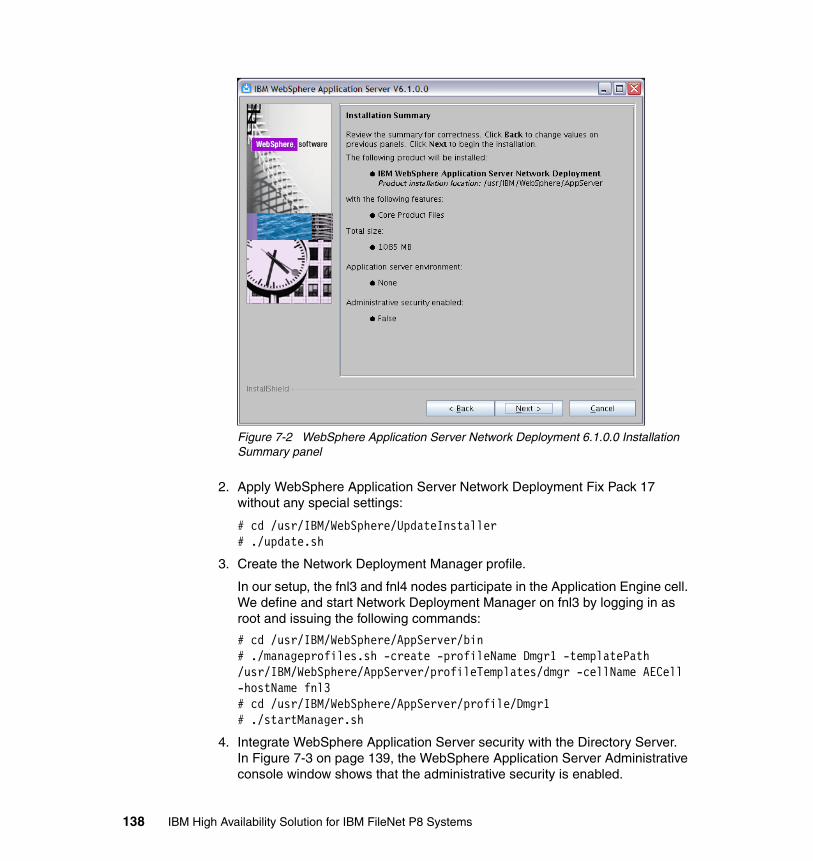
Figure 7-2 WebSphere Application Server Network Deployment 6.1.0.0 Installation Summary panel
2. Apply WebSphere Application Server Network Deployment Fix Pack 17 without any special settings:
# cd /usr/IBM/WebSphere/UpdateInstaller# ./update.sh
3. Create the Network Deployment Manager profile.
In our setup, the fnl3 and fnl4 nodes participate in the Application Engine cell. We define and start Network Deployment Manager on fnl3 by logging in as root and issuing the following commands:
# cd /usr/IBM/WebSphere/AppServer/bin# ./manageprofiles.sh -create -profileName Dmgr1 -templatePath /usr/IBM/WebSphere/AppServer/profileTemplates/dmgr -cellName AECell -hostName fnl3# cd /usr/IBM/WebSphere/AppServer/profile/Dmgr1# ./startManager.sh
4. Integrate WebSphere Application Server security with the Directory Server.In Figure 7-3 on page 139, the WebSphere Application Server Administrative console window shows that the administrative security is enabled.
138 IBM High Availability Solution for IBM FileNet P8 Systems
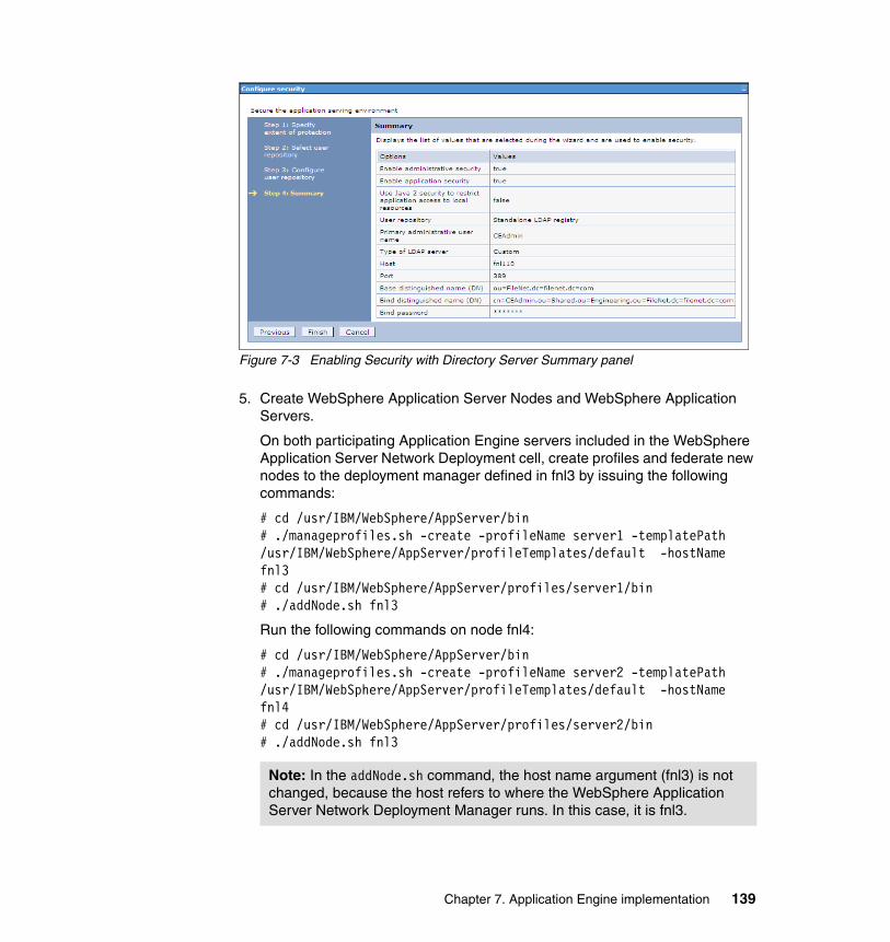
Figure 7-3 Enabling Security with Directory Server Summary panel
5. Create WebSphere Application Server Nodes and WebSphere Application Servers.
On both participating Application Engine servers included in the WebSphere Application Server Network Deployment cell, create profiles and federate new nodes to the deployment manager defined in fnl3 by issuing the following commands:
# cd /usr/IBM/WebSphere/AppServer/bin# ./manageprofiles.sh -create -profileName server1 -templatePath /usr/IBM/WebSphere/AppServer/profileTemplates/default -hostName fnl3 # cd /usr/IBM/WebSphere/AppServer/profiles/server1/bin# ./addNode.sh fnl3
Run the following commands on node fnl4:
# cd /usr/IBM/WebSphere/AppServer/bin# ./manageprofiles.sh -create -profileName server2 -templatePath /usr/IBM/WebSphere/AppServer/profileTemplates/default -hostName fnl4 # cd /usr/IBM/WebSphere/AppServer/profiles/server2/bin# ./addNode.sh fnl3
Note: In the addNode.sh command, the host name argument (fnl3) is not changed, because the host refers to where the WebSphere Application Server Network Deployment Manager runs. In this case, it is fnl3.
Chapter 7. Application Engine implementation 139
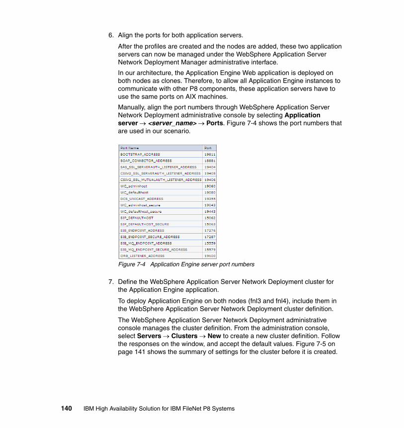
6. Align the ports for both application servers.
After the profiles are created and the nodes are added, these two application servers can now be managed under the WebSphere Application Server Network Deployment Manager administrative interface.
In our architecture, the Application Engine Web application is deployed on both nodes as clones. Therefore, to allow all Application Engine instances to communicate with other P8 components, these application servers have to use the same ports on AIX machines.
Manually, align the port numbers through WebSphere Application Server Network Deployment administrative console by selecting Application server → <server_name> → Ports. Figure 7-4 shows the port numbers that are used in our scenario.
Figure 7-4 Application Engine server port numbers
7. Define the WebSphere Application Server Network Deployment cluster for the Application Engine application.
To deploy Application Engine on both nodes (fnl3 and fnl4), include them in the WebSphere Application Server Network Deployment cluster definition.
The WebSphere Application Server Network Deployment administrative console manages the cluster definition. From the administration console, select Servers → Clusters → New to create a new cluster definition. Follow the responses on the window, and accept the default values. Figure 7-5 on page 141 shows the summary of settings for the cluster before it is created.
140 IBM High Availability Solution for IBM FileNet P8 Systems
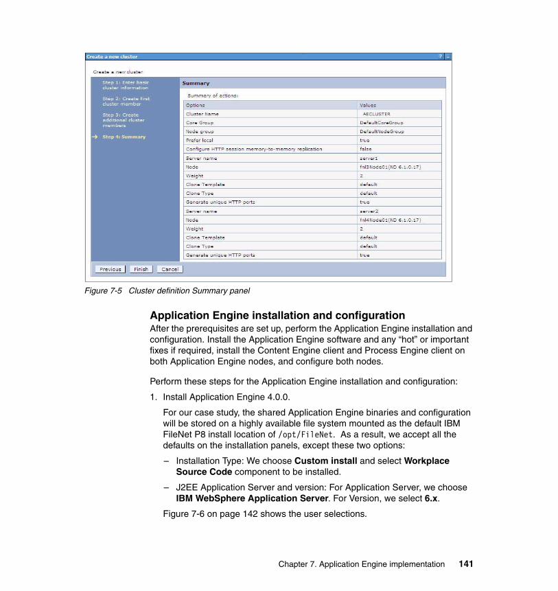
Figure 7-5 Cluster definition Summary panel
Application Engine installation and configurationAfter the prerequisites are set up, perform the Application Engine installation and configuration. Install the Application Engine software and any “hot” or important fixes if required, install the Content Engine client and Process Engine client on both Application Engine nodes, and configure both nodes.
Perform these steps for the Application Engine installation and configuration:
1. Install Application Engine 4.0.0.
For our case study, the shared Application Engine binaries and configuration will be stored on a highly available file system mounted as the default IBM FileNet P8 install location of /opt/FileNet. As a result, we accept all the defaults on the installation panels, except these two options:
– Installation Type: We choose Custom install and select Workplace Source Code component to be installed.
– J2EE Application Server and version: For Application Server, we choose IBM WebSphere Application Server. For Version, we select 6.x.
Figure 7-6 on page 142 shows the user selections.
Chapter 7. Application Engine implementation 141
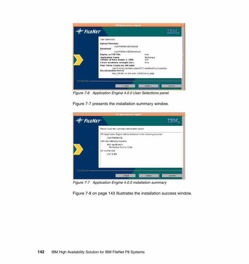
Figure 7-6 Application Engine 4.0.0 User Selections panel
Figure 7-7 presents the installation summary window.
Figure 7-7 Application Engine 4.0.0 installation summary
Figure 7-8 on page 143 illustrates the installation success window.
142 IBM High Availability Solution for IBM FileNet P8 Systems
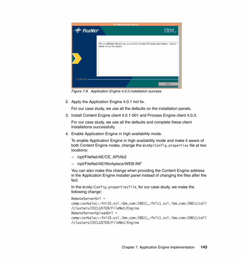
Figure 7-8 Application Engine 4.0.0 installation success
2. Apply the Application Engine 4.0.1 hot fix.
For our case study, we use all the defaults on the installation panels.
3. Install Content Engine client 4.0.1-001 and Process Engine client 4.0.3.
For our case study, we use all the defaults and complete these client installations successfully.
4. Enable Application Engine in high availability mode.
To enable Application Engine in high availability mode and make it aware of both Content Engine nodes, change the WcmApiConfig.properties file at two locations:
– /opt/FileNet/AE/CE_API/lib2
– /opt/FileNet/AE/Workplace/WEB-INF
You can also make this change when providing the Content Engine address in the Application Engine installer panel instead of changing the files after the fact.
In the WcmApiConfig.propertiesfile, for our case study, we make the following change:
RemoteServerUrl = cemp:corbaloc::fnl10.svl.ibm.com:19811,:fnl11.svl.ibm.com:19811/cell/clusters/CECLUSTER/FileNet/EngineRemoteServerUploadUrl = cemp:corbaloc::fnl10.svl.ibm.com:19811,:fnl11.svl.ibm.com:19811/cell/clusters/CECLUSTER/FileNet/Engine
Chapter 7. Application Engine implementation 143
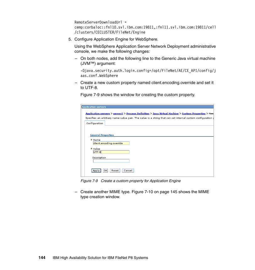
RemoteServerDownloadUrl = cemp:corbaloc::fnl10.svl.ibm.com:19811,:fnl11.svl.ibm.com:19811/cell/clusters/CECLUSTER/FileNet/Engine
5. Configure Application Engine for WebSphere.
Using the WebSphere Application Server Network Deployment administrative console, we make the following changes:
– On both nodes, add the following line to the Generic Java virtual machine (JVM™) argument:
-Djava.security.auth.login.config=/opt/FileNet/AE/CE_API/config/jaas.conf.WebSphere
– Create a new custom property named client.encoding.override and set it to UTF-8.
Figure 7-9 shows the window for creating the custom property.
Figure 7-9 Create a custom property for Application Engine
– Create another MIME type. Figure 7-10 on page 145 shows the MIME type creation window.
144 IBM High Availability Solution for IBM FileNet P8 Systems
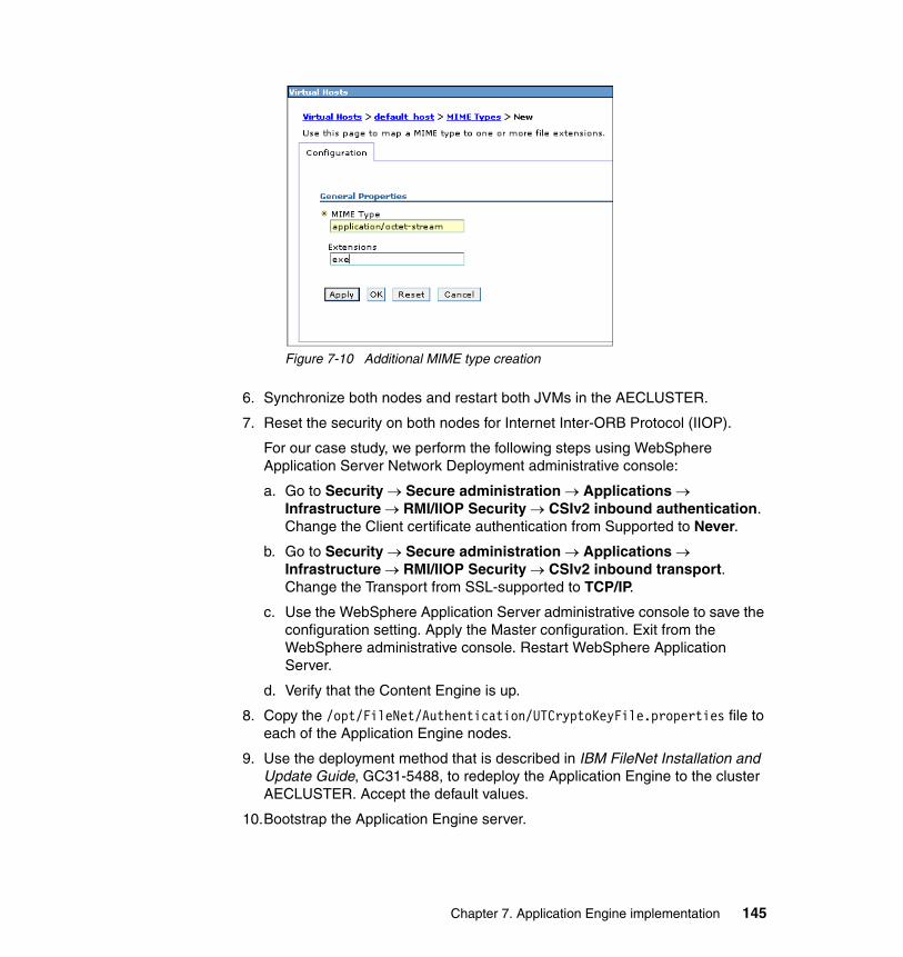
Figure 7-10 Additional MIME type creation
6. Synchronize both nodes and restart both JVMs in the AECLUSTER.
7. Reset the security on both nodes for Internet Inter-ORB Protocol (IIOP).
For our case study, we perform the following steps using WebSphere Application Server Network Deployment administrative console:
a. Go to Security → Secure administration → Applications → Infrastructure → RMI/IIOP Security → CSIv2 inbound authentication. Change the Client certificate authentication from Supported to Never.
b. Go to Security → Secure administration → Applications → Infrastructure → RMI/IIOP Security → CSIv2 inbound transport. Change the Transport from SSL-supported to TCP/IP.
c. Use the WebSphere Application Server administrative console to save the configuration setting. Apply the Master configuration. Exit from the WebSphere administrative console. Restart WebSphere Application Server.
d. Verify that the Content Engine is up.
8. Copy the /opt/FileNet/Authentication/UTCryptoKeyFile.properties file to each of the Application Engine nodes.
9. Use the deployment method that is described in IBM FileNet Installation and Update Guide, GC31-5488, to redeploy the Application Engine to the cluster AECLUSTER. Accept the default values.
10.Bootstrap the Application Engine server.
Chapter 7. Application Engine implementation 145

7.5 High availability tests at the Application Engine level
After you complete the setup of each component in the high availability P8 environment, make sure that you perform component testing before continuing with the rest of the implementation.
In this section, we discuss the failover tests at the Application Engine component level. Table 7-3 shows the high availability tests that we performed for our case study in the lab and the results of these tests.
Table 7-3 Application Engine component-level high availability test scenarios
7.5.1 Application Engine basic availability test
The basic test to see whether Application Engine is available is by testing the Workplace application (with the assumption that the load balancer and IBM HTTP Server are installed correctly and successfully). When launching the Workplace application through the URL, if you get to the Workplace login window, Application Engine is up and running. If you do not get to the login window, Application Engine is not running.
Sr. No. Test Expected result Actual result
Test 1 Basic availability test: Test the Workplace application by going to the Workplace URL http://9.30.188.90/Workplace.Note: Use the Application Engine virtual IP address for testing.
The URL works.Response is from either one of the Application Engine nodes.
See 7.5.1, “Application Engine basic availability test” on page 146.
Test 2 Node availability test 1: Test the Workplace application while Application Engine node 2 (AE2) is down. Use the same URL as test 1.
The URL works. Response is from AE1.
See 7.5.2, “Application Engine node availability test 1” on page 148.
Test 3 Node availability test 2: Test the Workplace application while Application Engine node 1 (AE1) is down.
The URL works. Response is from AE2.
See 7.5.3, “Application Engine node availability test 2” on page 149.
Note: Without the database and Content Engine, we only see and test the login window. We get an error if we try to carry out the actual login operation.
146 IBM High Availability Solution for IBM FileNet P8 Systems
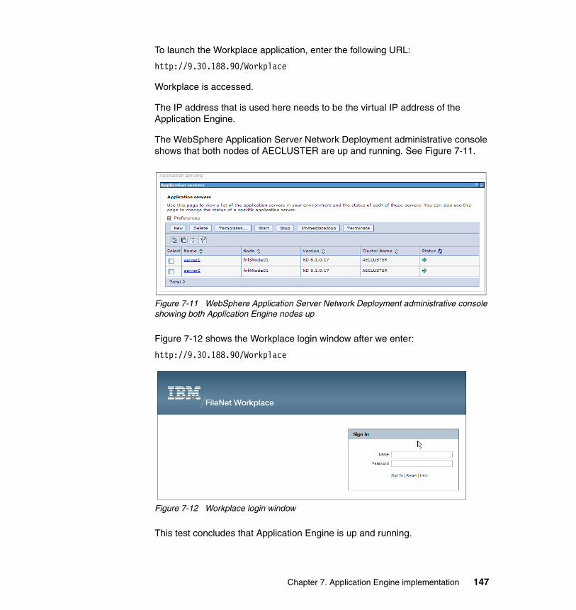
To launch the Workplace application, enter the following URL:
http://9.30.188.90/Workplace
Workplace is accessed.
The IP address that is used here needs to be the virtual IP address of the Application Engine.
The WebSphere Application Server Network Deployment administrative console shows that both nodes of AECLUSTER are up and running. See Figure 7-11.
Figure 7-11 WebSphere Application Server Network Deployment administrative console showing both Application Engine nodes up
Figure 7-12 shows the Workplace login window after we enter:
http://9.30.188.90/Workplace
Figure 7-12 Workplace login window
This test concludes that Application Engine is up and running.
Chapter 7. Application Engine implementation 147
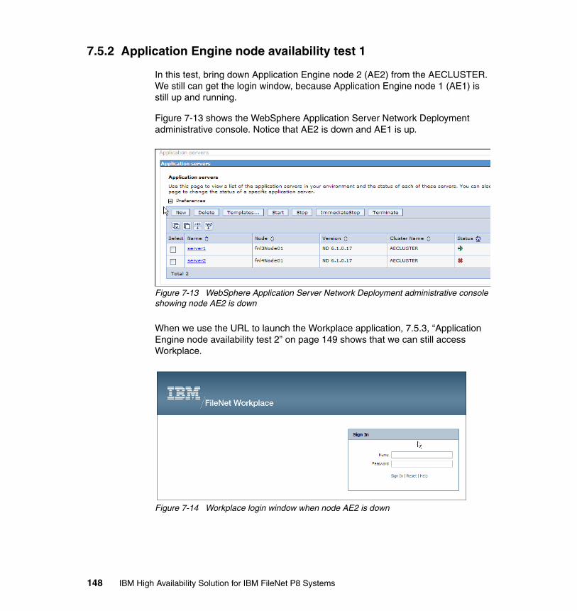
7.5.2 Application Engine node availability test 1
In this test, bring down Application Engine node 2 (AE2) from the AECLUSTER. We still can get the login window, because Application Engine node 1 (AE1) is still up and running.
Figure 7-13 shows the WebSphere Application Server Network Deployment administrative console. Notice that AE2 is down and AE1 is up.
Figure 7-13 WebSphere Application Server Network Deployment administrative console showing node AE2 is down
When we use the URL to launch the Workplace application, 7.5.3, “Application Engine node availability test 2” on page 149 shows that we can still access Workplace.
Figure 7-14 Workplace login window when node AE2 is down
148 IBM High Availability Solution for IBM FileNet P8 Systems
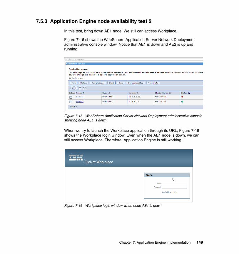
7.5.3 Application Engine node availability test 2
In this test, bring down AE1 node. We still can access Workplace.
Figure 7-16 shows the WebSphere Application Server Network Deployment administrative console window. Notice that AE1 is down and AE2 is up and running.
Figure 7-15 WebSphere Application Server Network Deployment administrative console showing node AE1 is down
When we try to launch the Workplace application through its URL, Figure 7-16 shows the Workplace login window. Even when the AE1 node is down, we can still access Workplace. Therefore, Application Engine is still working.
Figure 7-16 Workplace login window when node AE1 is down
Chapter 7. Application Engine implementation 149

150 IBM High Availability Solution for IBM FileNet P8 Systems
Chapter 8. Content Engine implementation
This chapter describes the high availability (HA) options for Content Engine (CE) and our case study setup in relation to it. We also discuss the practical, step-by-step procedures that we use to implement high availability for Content Engine.
We discuss the following topics:
� Introduction� High availability options for Content Engine� Case study design� Setting up the active/active Content Engine cluster (farm)� High availability tests at the Content Engine level
8
© Copyright IBM Corp. 2009. All rights reserved. 151
8.1 Introduction
Content Engine provides access, storage, and other management for content. It is designed to handle the heavy demands of a large enterprise. Content Engine is capable of managing enterprise-wide workflow objects, custom objects, and documents by offering powerful and easy-to-use administrative tools. Using these administrative tools, an administrator can create and manage the classes, properties, storage, and metadata that form the foundation of an Enterprise Content Management (ECM) system. It is critical to provide high availability for Content Engine in the overall high availability of the IBM FileNet P8 solution.
For an overview of Content Engine, its features and architecture, refer to 2.2, “Content Engine” on page 21.
8.2 High availability options for Content Engine
Content Engine is the central point of the IBM FileNet P8 repository. Content Engine must be highly available. If Content Engine fails, users no longer have access to existing content, and they cannot add new content. This inaccessibility occurs from API-based programs, as well as from other components, such as the Application Engine (AE) and Process Engine (PE). The importance of Content Engine must be a key factor in creating any IBM FileNet P8 HA environment.
When Content Engine is unavailable, neither the content nor the processes can be routed (although in certain cases, there are still operations that will succeed, at least for users who are already logged in). In comparison, if a Process Engine fails, the users can still ingest and retrieve content from the repository. If an Application Engine fails, the Workplace application cannot be accessed; however, the repository or Content Engine can still be accessed through a custom, API-based application. In the case of a Content Engine failure, the entire repository becomes inaccessible.
Because Content Engine is implemented as a Java 2 Platform, Enterprise Edition (J2EE) application running within a J2EE application server, it can exploit all the scalability and high availability options that are available for J2EE application servers.
The following options are available for making Content Engine highly available:
� Active/active cluster
In an active/active cluster (farm) configuration, two or more application server instances are configured to serve the same application workload. These application server instances can reside on the same physical machine or
152 IBM High Availability Solution for IBM FileNet P8 Systems

separate machines. The active/active cluster can be front-ended by using a load balancer. And, the traffic can be redirected over to any of the active instances. In an active/active cluster, because there are more than one instance available, the load sharing is more effective and the hardware cost is more justifiable to the business.
� Active/passive cluster
In an active/passive cluster, only one instance of the application server is running. The specific node that hosts the application load in an active/passive cluster is called the active node. The secondary node that can potentially host the application load is called the passive node. In an active/passive cluster at any time, there is only one node active to cater to the application load.
The application metadata that is stored in a Content Engine database must also be made highly available in both scenarios.
The file storage areas for Content Engine must be accessible to all Content Engines in a P8 domain, whether those Content Engines are farmed or not. Typically, the file storage areas are accessed in a shared network, such as Common Internet File System (CIFS), Network File System (NFS), or Distributed File Service (DFS).
In a high availability deployment, each file storage area must be deployed on highly available storage that has built-in redundancy for all components, so that the file storage area is not a single point of failure (for example, RAID arrays for storage redundancy, redundant network heads, and redundant power supplies).
It is beyond the scope of this book to describe the details of providing highly available storage. Refer to your storage vendor for more information.
8.3 Case study design
For our case study setup, we choose the recommended active/active cluster (farm) configuration for making the Content Engine highly available. There are two nodes running the Content Engines. Both nodes run the IBM AIX operating system.
Table 8-1 shows the high availability environment details.
Table 8-1 Content Engine case study setup
Scenario Active/active cluster
Operating system IBM AIX 5.3 Technology Level 8 Service Pack 3: 5300-08-03-0831
Chapter 8. Content Engine implementation 153
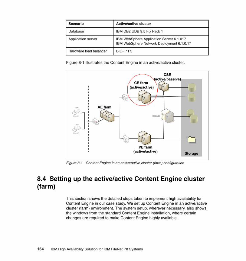
Figure 8-1 illustrates the Content Engine in an active/active cluster.
Figure 8-1 Content Engine in an active/active cluster (farm) configuration
8.4 Setting up the active/active Content Engine cluster (farm)
This section shows the detailed steps taken to implement high availability for Content Engine in our case study. We set up Content Engine in an active/active cluster (farm) environment. The system setup, wherever necessary, also shows the windows from the standard Content Engine installation, where certain changes are required to make Content Engine highly available.
Database IBM DB2 UDB 9.5 Fix Pack 1
Application server IBM WebSphere Application Server 6.1.017IBM WebSphere Network Deployment 6.1.0.17
Hardware load balancer BIG-IP F5
Scenario Active/active cluster
CE farm (active/active)
CE farm (active/active)
Client 1
Client N
StorageStorage
RDBMSRDBMS
PE farm(active/active)
PE farm(active/active)
CSE(active/passive)
CSE(active/passive)
AE farmAE farm
154 IBM High Availability Solution for IBM FileNet P8 Systems
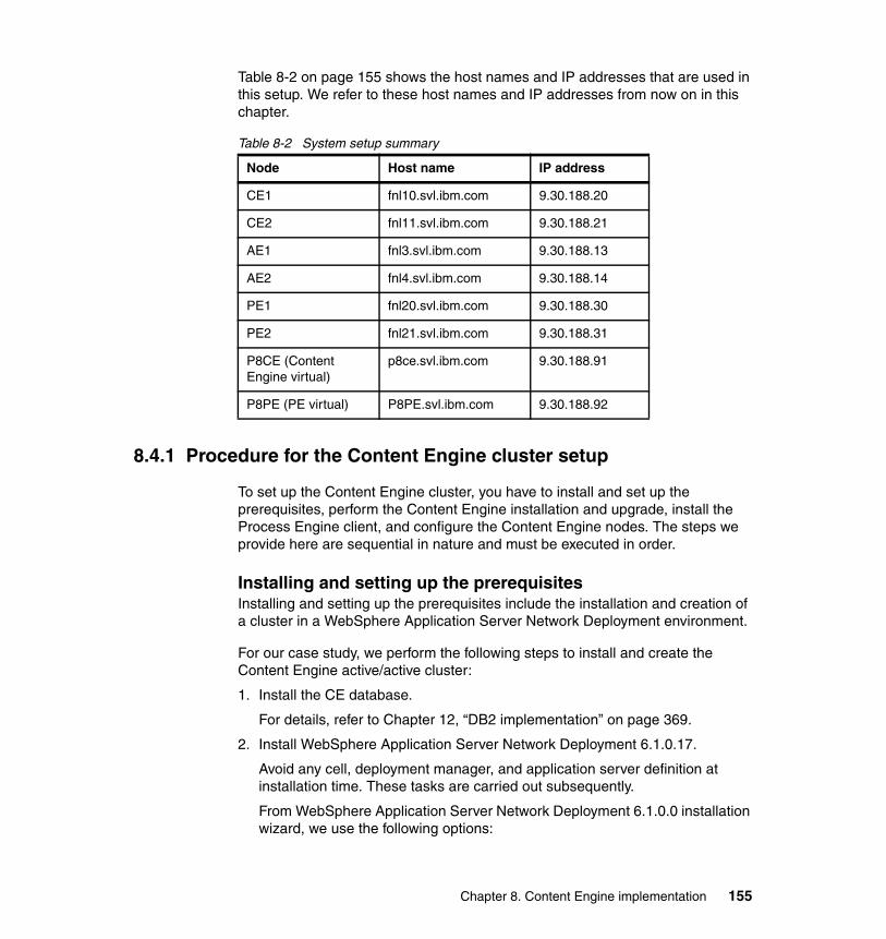
Table 8-2 on page 155 shows the host names and IP addresses that are used in this setup. We refer to these host names and IP addresses from now on in this chapter.
Table 8-2 System setup summary
8.4.1 Procedure for the Content Engine cluster setup
To set up the Content Engine cluster, you have to install and set up the prerequisites, perform the Content Engine installation and upgrade, install the Process Engine client, and configure the Content Engine nodes. The steps we provide here are sequential in nature and must be executed in order.
Installing and setting up the prerequisitesInstalling and setting up the prerequisites include the installation and creation of a cluster in a WebSphere Application Server Network Deployment environment.
For our case study, we perform the following steps to install and create the Content Engine active/active cluster:
1. Install the CE database.
For details, refer to Chapter 12, “DB2 implementation” on page 369.
2. Install WebSphere Application Server Network Deployment 6.1.0.17.
Avoid any cell, deployment manager, and application server definition at installation time. These tasks are carried out subsequently.
From WebSphere Application Server Network Deployment 6.1.0.0 installation wizard, we use the following options:
Node Host name IP address
CE1 fnl10.svl.ibm.com 9.30.188.20
CE2 fnl11.svl.ibm.com 9.30.188.21
AE1 fnl3.svl.ibm.com 9.30.188.13
AE2 fnl4.svl.ibm.com 9.30.188.14
PE1 fnl20.svl.ibm.com 9.30.188.30
PE2 fnl21.svl.ibm.com 9.30.188.31
P8CE (Content Engine virtual)
p8ce.svl.ibm.com 9.30.188.91
P8PE (PE virtual) P8PE.svl.ibm.com 9.30.188.92
Chapter 8. Content Engine implementation 155
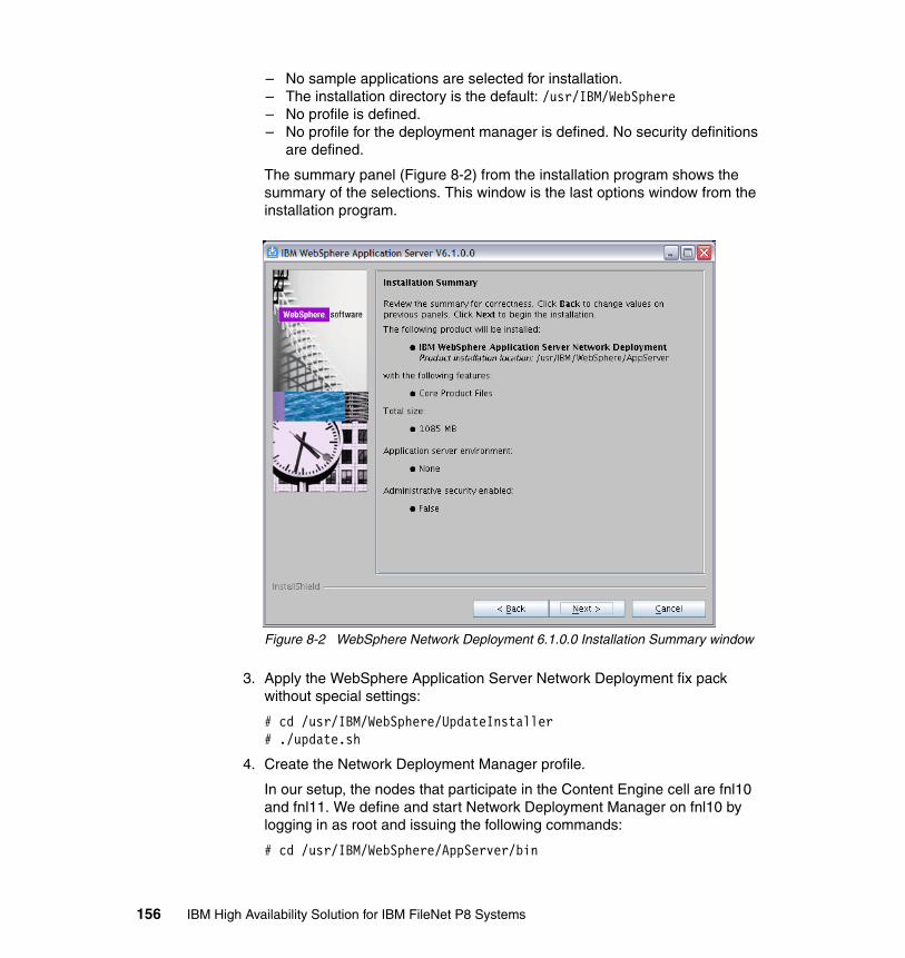
– No sample applications are selected for installation.– The installation directory is the default: /usr/IBM/WebSphere– No profile is defined.– No profile for the deployment manager is defined. No security definitions
are defined.
The summary panel (Figure 8-2) from the installation program shows the summary of the selections. This window is the last options window from the installation program.
Figure 8-2 WebSphere Network Deployment 6.1.0.0 Installation Summary window
3. Apply the WebSphere Application Server Network Deployment fix pack without special settings:
# cd /usr/IBM/WebSphere/UpdateInstaller# ./update.sh
4. Create the Network Deployment Manager profile.
In our setup, the nodes that participate in the Content Engine cell are fnl10 and fnl11. We define and start Network Deployment Manager on fnl10 by logging in as root and issuing the following commands:
# cd /usr/IBM/WebSphere/AppServer/bin
156 IBM High Availability Solution for IBM FileNet P8 Systems
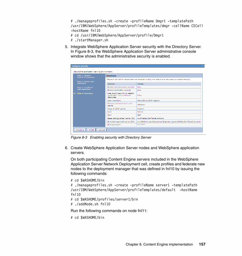
# ./manageprofiles.sh -create -profileName Dmgr1 -templatePath /usr/IBM/WebSphere/AppServer/profileTemplates/dmgr -cellName CECell -hostName fnl10# cd /usr/IBM/WebSphere/AppServer/profile/Dmgr1# ./startManager.sh
5. Integrate WebSphere Application Server security with the Directory Server.In Figure 8-3, the WebSphere Application Server administrative console window shows that the administrative security is enabled.
Figure 8-3 Enabling security with Directory Server
6. Create WebSphere Application Server nodes and WebSphere application servers.
On both participating Content Engine servers included in the WebSphere Application Server Network Deployment cell, create profiles and federate new nodes to the deployment manager that was defined in fnl10 by issuing the following commands:
# cd $WASHOME/bin# ./manageprofiles.sh -create -profileName server1 -templatePath /usr/IBM/WebSphere/AppServer/profileTemplates/default -hostName fnl10 # cd $WASHOME/profiles/server1/bin# ./addNode.sh fnl10
Run the following commands on node fnl11:
# cd $WASHOME/bin
Chapter 8. Content Engine implementation 157
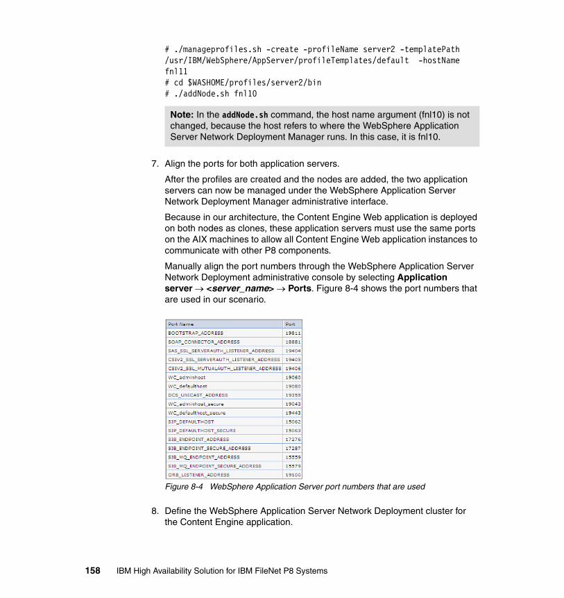
# ./manageprofiles.sh -create -profileName server2 -templatePath /usr/IBM/WebSphere/AppServer/profileTemplates/default -hostName fnl11 # cd $WASHOME/profiles/server2/bin# ./addNode.sh fnl10
7. Align the ports for both application servers.
After the profiles are created and the nodes are added, the two application servers can now be managed under the WebSphere Application Server Network Deployment Manager administrative interface.
Because in our architecture, the Content Engine Web application is deployed on both nodes as clones, these application servers must use the same ports on the AIX machines to allow all Content Engine Web application instances to communicate with other P8 components.
Manually align the port numbers through the WebSphere Application Server Network Deployment administrative console by selecting Application server → <server_name> → Ports. Figure 8-4 shows the port numbers that are used in our scenario.
Figure 8-4 WebSphere Application Server port numbers that are used
8. Define the WebSphere Application Server Network Deployment cluster for the Content Engine application.
Note: In the addNode.sh command, the host name argument (fnl10) is not changed, because the host refers to where the WebSphere Application Server Network Deployment Manager runs. In this case, it is fnl10.
158 IBM High Availability Solution for IBM FileNet P8 Systems
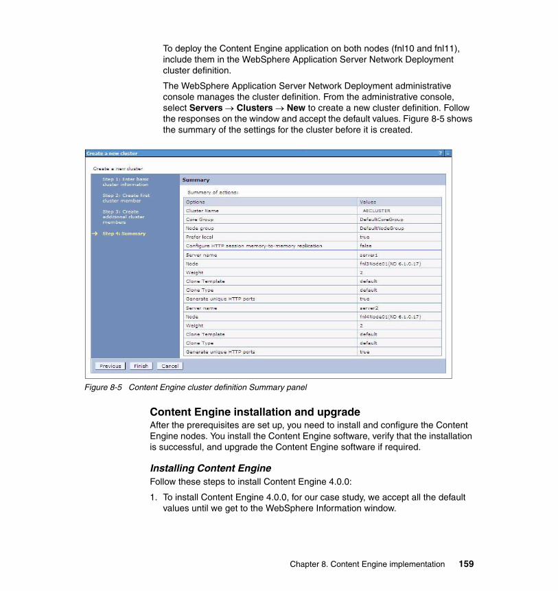
To deploy the Content Engine application on both nodes (fnl10 and fnl11), include them in the WebSphere Application Server Network Deployment cluster definition.
The WebSphere Application Server Network Deployment administrative console manages the cluster definition. From the administrative console, select Servers → Clusters → New to create a new cluster definition. Follow the responses on the window and accept the default values. Figure 8-5 shows the summary of the settings for the cluster before it is created.
Figure 8-5 Content Engine cluster definition Summary panel
Content Engine installation and upgradeAfter the prerequisites are set up, you need to install and configure the Content Engine nodes. You install the Content Engine software, verify that the installation is successful, and upgrade the Content Engine software if required.
Installing Content EngineFollow these steps to install Content Engine 4.0.0:
1. To install Content Engine 4.0.0, for our case study, we accept all the default values until we get to the WebSphere Information window.
Chapter 8. Content Engine implementation 159
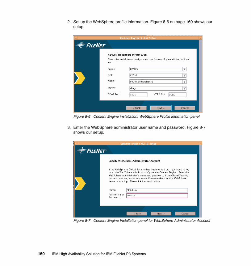
2. Set up the WebSphere profile information. Figure 8-6 on page 160 shows our setup.
Figure 8-6 Content Engine installation: WebSphere Profile information panel
3. Enter the WebSphere administrator user name and password. Figure 8-7 shows our setup.
Figure 8-7 Content Engine Installation panel for WebSphere Administrator Account
160 IBM High Availability Solution for IBM FileNet P8 Systems
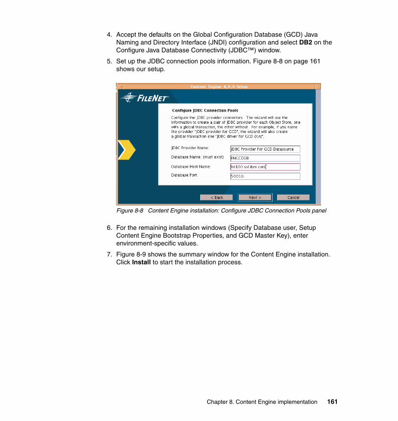
4. Accept the defaults on the Global Configuration Database (GCD) Java Naming and Directory Interface (JNDI) configuration and select DB2 on the Configure Java Database Connectivity (JDBC™) window.
5. Set up the JDBC connection pools information. Figure 8-8 on page 161 shows our setup.
Figure 8-8 Content Engine installation: Configure JDBC Connection Pools panel
6. For the remaining installation windows (Specify Database user, Setup Content Engine Bootstrap Properties, and GCD Master Key), enter environment-specific values.
7. Figure 8-9 shows the summary window for the Content Engine installation. Click Install to start the installation process.
Chapter 8. Content Engine implementation 161
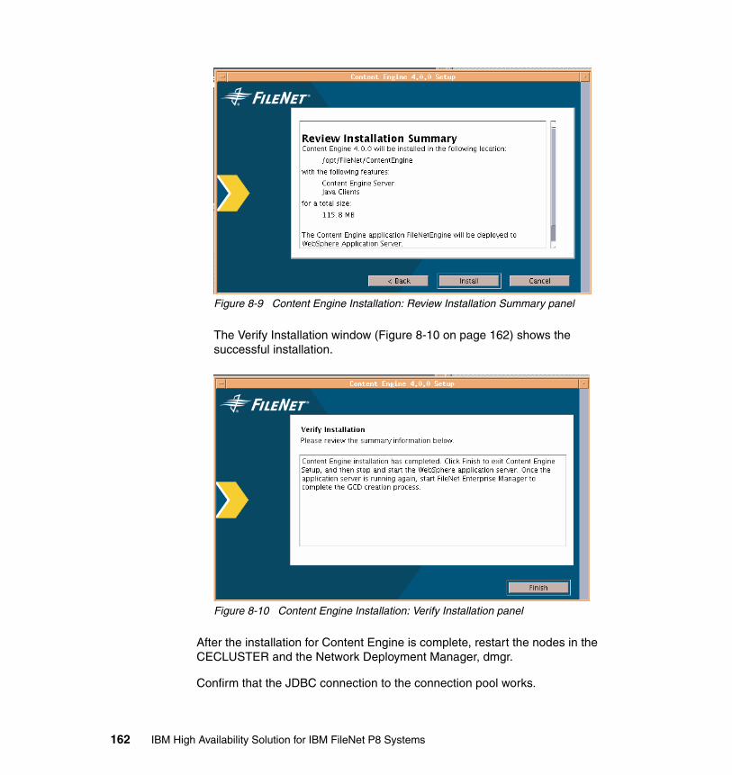
Figure 8-9 Content Engine Installation: Review Installation Summary panel
The Verify Installation window (Figure 8-10 on page 162) shows the successful installation.
Figure 8-10 Content Engine Installation: Verify Installation panel
After the installation for Content Engine is complete, restart the nodes in the CECLUSTER and the Network Deployment Manager, dmgr.
Confirm that the JDBC connection to the connection pool works.
162 IBM High Availability Solution for IBM FileNet P8 Systems
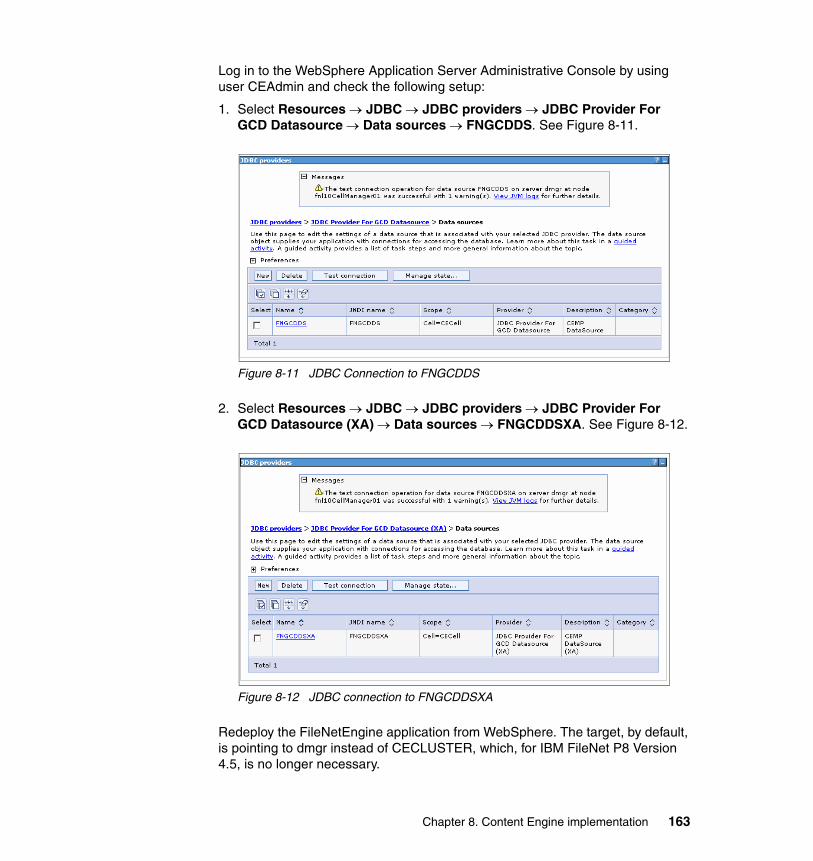
Log in to the WebSphere Application Server Administrative Console by using user CEAdmin and check the following setup:
1. Select Resources → JDBC → JDBC providers → JDBC Provider For GCD Datasource → Data sources → FNGCDDS. See Figure 8-11.
Figure 8-11 JDBC Connection to FNGCDDS
2. Select Resources → JDBC → JDBC providers → JDBC Provider For GCD Datasource (XA) → Data sources → FNGCDDSXA. See Figure 8-12.
Figure 8-12 JDBC connection to FNGCDDSXA
Redeploy the FileNetEngine application from WebSphere. The target, by default, is pointing to dmgr instead of CECLUSTER, which, for IBM FileNet P8 Version 4.5, is no longer necessary.
Chapter 8. Content Engine implementation 163

Deploy the newly modified WebSphere EAR file for the Content Engine. The modified file is called Engine-ws.ear file. Follow these steps to deploy the Content Engine application:
1. From the WebSphere administrative console, navigate to Applications → Install New Application.
From the EAR/WAR/JAR module page, perform these steps:
a. In the Remote file system, browse to the location of the new Engine-ws.ear file, select it, and click Next.
b. Accept the default values, except in step 3 (of the WebSphere Administrative console) deployment process, select both Engine-init.war and FileNet CE-MP WebService, and set their values to default_host.
c. Save your changes to the master configuration.
2. Complete the post-deployment configuration on WebSphere 6.1.x:
a. From the WebSphere administrative console, navigate to Applications → Enterprise Applications → FileNetEngine → Manage Modules → FileNet P8 Connector → Resource Adapter → J2C connection factories.
b. Click New to create a new J2EE Connector architecture (J2C) connection factory.
c. Fill in the connection factory properties, and then, click Apply:
• Name: FileNetConnectionFactory• JNDI Name: FileNet/Local/ConnectionFactory
d. Under Container-managed authentication, change the following three entries to None, and click Apply:
• Container-managed authentication alias• Authentication preference• Mapping-configuration alias
e. Click Connection Pool Properties, enter the values for the following properties, and then, click Apply:
• Max Connections: 100• Min Connections: 10• Save the changes to the master configuration.
Note: For Network Deployment configurations, deploy the Content Engine application to all server instances and Web servers that will run the Content Engine application.
164 IBM High Availability Solution for IBM FileNet P8 Systems
3. Continue from the WebSphere administrative console, change the class loading, and update the detection settings:
a. Navigate to Applications → Enterprise Applications → FileNet Engine → Class Loading and update detection.
b. Set the following configuration settings, and then, click Apply:
• Change the polling interval to 3 (seconds).
• Change the Class loader order to Classes loaded with application class loader first.
• Change WAR class loader policy to Single class loader for application.
• Save changes to the master configuration.
4. Continue from the WebSphere administrative console, change the FileNet CEMP Web Service setting:
a. Navigate to Applications → Enterprise Applications → FileNetEngine → Manage Modules → FileNet CEMP Web Service.
b. Change the class loader order to Classes loaded with application class loader first.
c. Click Apply.
d. Save changes to the master configuration.
5. Stop and start the application server.
Verify the Content Engine installationAlways test whether Content Engine is running on both nodes before you continue with the rest of the setup.
From a browser, enter the following URL:
http://<Content Engine host name>:19080/FileNet/Engine
For our case study, we use the following URL to verify whether the Content Engine node 1 (CE1, fnl10) installation is successful:
http://fnl10.svl.ibm.com:19080/FileNet/Engine
Figure 8-13 shows that Content Engine is up and running on node CE1.
Chapter 8. Content Engine implementation 165
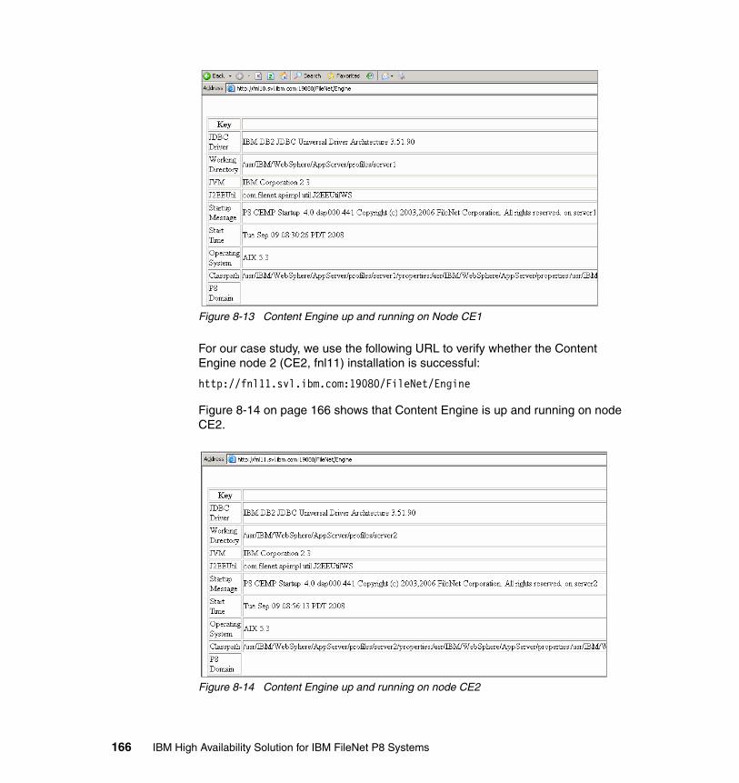
Figure 8-13 Content Engine up and running on Node CE1
For our case study, we use the following URL to verify whether the Content Engine node 2 (CE2, fnl11) installation is successful:
http://fnl11.svl.ibm.com:19080/FileNet/Engine
Figure 8-14 on page 166 shows that Content Engine is up and running on node CE2.
Figure 8-14 Content Engine up and running on node CE2
166 IBM High Availability Solution for IBM FileNet P8 Systems
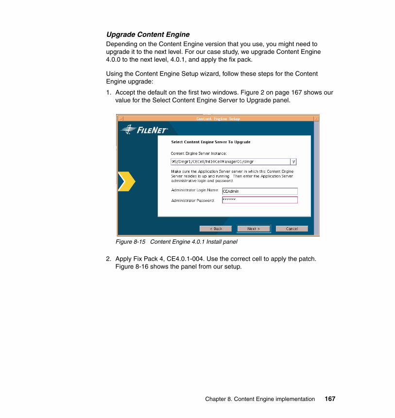
Upgrade Content EngineDepending on the Content Engine version that you use, you might need to upgrade it to the next level. For our case study, we upgrade Content Engine 4.0.0 to the next level, 4.0.1, and apply the fix pack.
Using the Content Engine Setup wizard, follow these steps for the Content Engine upgrade:
1. Accept the default on the first two windows. Figure 2 on page 167 shows our value for the Select Content Engine Server to Upgrade panel.
Figure 8-15 Content Engine 4.0.1 Install panel
2. Apply Fix Pack 4, CE4.0.1-004. Use the correct cell to apply the patch. Figure 8-16 shows the panel from our setup.
Chapter 8. Content Engine implementation 167
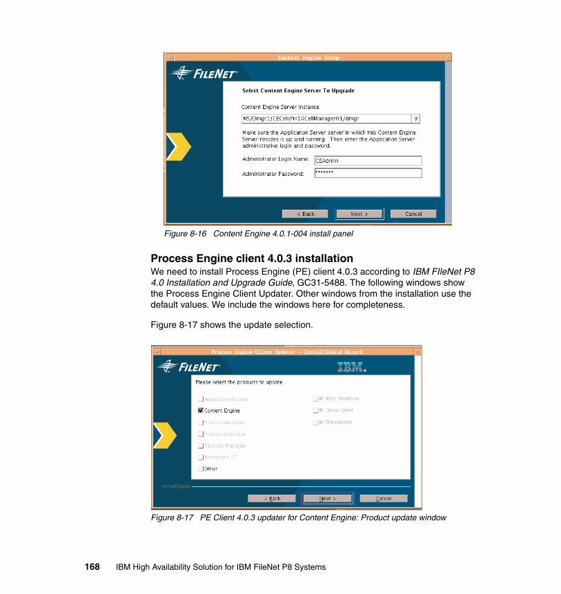
Figure 8-16 Content Engine 4.0.1-004 install panel
Process Engine client 4.0.3 installationWe need to install Process Engine (PE) client 4.0.3 according to IBM FIleNet P8 4.0 Installation and Upgrade Guide, GC31-5488. The following windows show the Process Engine Client Updater. Other windows from the installation use the default values. We include the windows here for completeness.
Figure 8-17 shows the update selection.
Figure 8-17 PE Client 4.0.3 updater for Content Engine: Product update window
168 IBM High Availability Solution for IBM FileNet P8 Systems
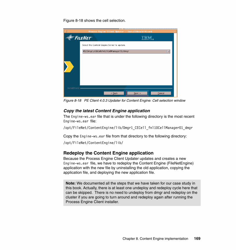
Figure 8-18 shows the cell selection.
Figure 8-18 PE Client 4.0.3 Updater for Content Engine: Cell selection window
Copy the latest Content Engine applicationThe Engine-ws.ear file that is under the following directory is the most recent Engine-ws.ear file:
/opt/FileNet/ContentEngine/lib/Dmgr1_CECell_fnl10CellManager01_dmgr
Copy the Engine-ws.ear file from that directory to the following directory:
/opt/FileNet/ContentEngine/lib/
Redeploy the Content Engine application Because the Process Engine Client Updater updates and creates a new Engine-ws.ear file, we have to redeploy the Content Engine (FileNetEngine) application with the new file by uninstalling the old application, copying the application file, and deploying the new application file.
Note: We documented all the steps that we have taken for our case study in this book. Actually, there is at least one undeploy and redeploy cycle here that can be skipped. There is no need to undeploy from dmgr and redeploy on the cluster if you are going to turn around and redeploy again after running the Process Engine Client installer.
Chapter 8. Content Engine implementation 169
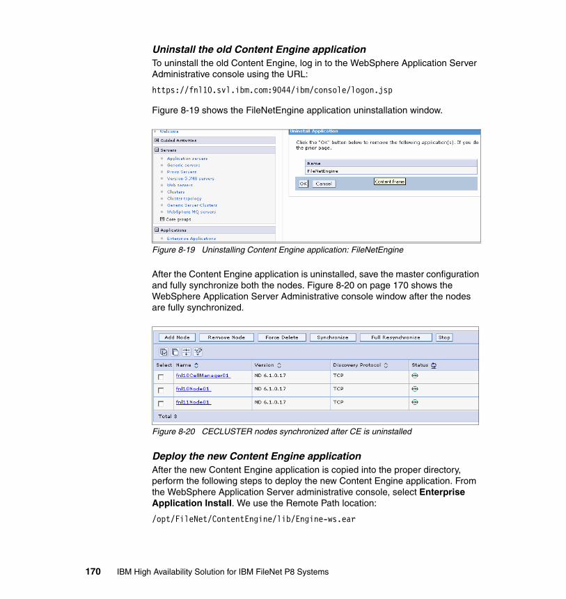
Uninstall the old Content Engine applicationTo uninstall the old Content Engine, log in to the WebSphere Application Server Administrative console using the URL:
https://fnl10.svl.ibm.com:9044/ibm/console/logon.jsp
Figure 8-19 shows the FileNetEngine application uninstallation window.
Figure 8-19 Uninstalling Content Engine application: FileNetEngine
After the Content Engine application is uninstalled, save the master configuration and fully synchronize both the nodes. Figure 8-20 on page 170 shows the WebSphere Application Server Administrative console window after the nodes are fully synchronized.
Figure 8-20 CECLUSTER nodes synchronized after CE is uninstalled
Deploy the new Content Engine applicationAfter the new Content Engine application is copied into the proper directory, perform the following steps to deploy the new Content Engine application. From the WebSphere Application Server administrative console, select Enterprise Application Install. We use the Remote Path location:
/opt/FileNet/ContentEngine/lib/Engine-ws.ear
170 IBM High Availability Solution for IBM FileNet P8 Systems
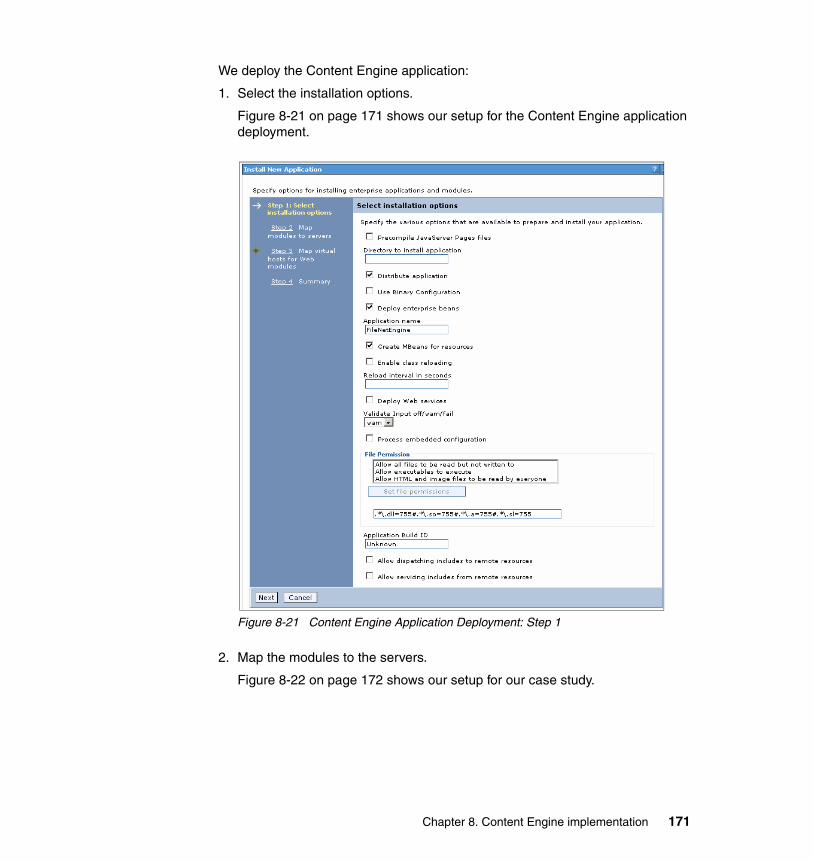
We deploy the Content Engine application:
1. Select the installation options.
Figure 8-21 on page 171 shows our setup for the Content Engine application deployment.
Figure 8-21 Content Engine Application Deployment: Step 1
2. Map the modules to the servers.
Figure 8-22 on page 172 shows our setup for our case study.
Chapter 8. Content Engine implementation 171
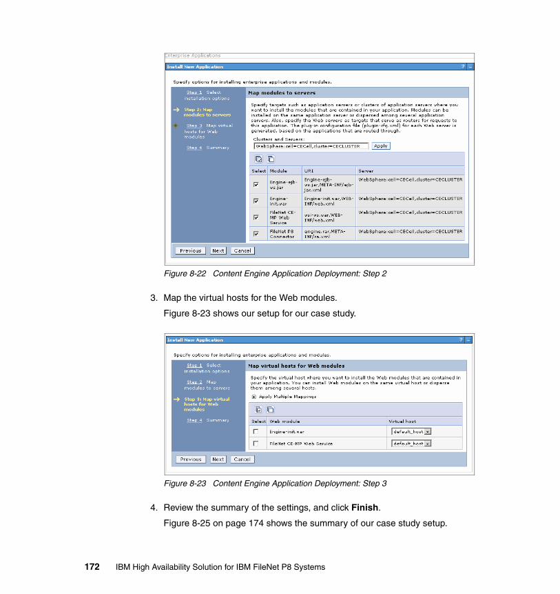
Figure 8-22 Content Engine Application Deployment: Step 2
3. Map the virtual hosts for the Web modules.
Figure 8-23 shows our setup for our case study.
Figure 8-23 Content Engine Application Deployment: Step 3
4. Review the summary of the settings, and click Finish.
Figure 8-25 on page 174 shows the summary of our case study setup.
172 IBM High Availability Solution for IBM FileNet P8 Systems
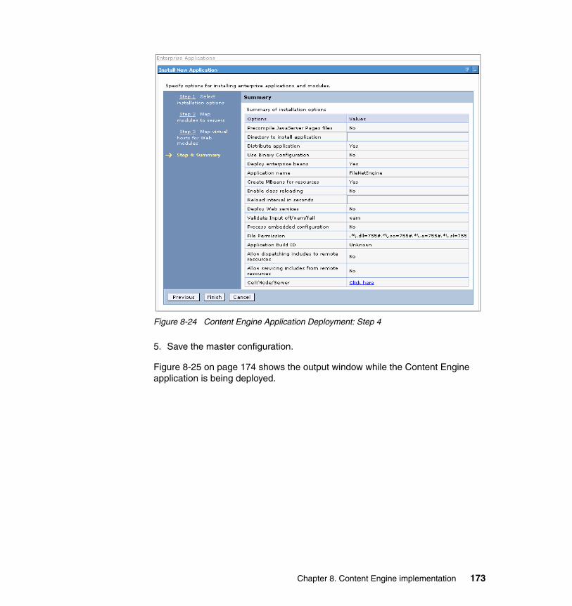
Figure 8-24 Content Engine Application Deployment: Step 4
5. Save the master configuration.
Figure 8-25 on page 174 shows the output window while the Content Engine application is being deployed.
Chapter 8. Content Engine implementation 173
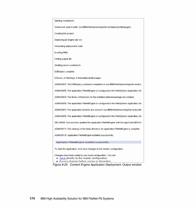
Figure 8-25 Content Engine Application Deployment: Output window
174 IBM High Availability Solution for IBM FileNet P8 Systems
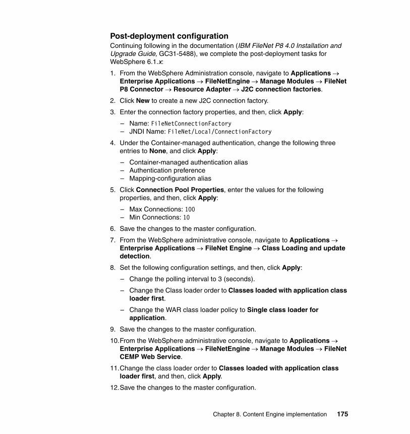
Post-deployment configurationContinuing following in the documentation (IBM FileNet P8 4.0 Installation and Upgrade Guide, GC31-5488), we complete the post-deployment tasks for WebSphere 6.1.x:
1. From the WebSphere Administration console, navigate to Applications → Enterprise Applications → FileNetEngine → Manage Modules → FileNet P8 Connector → Resource Adapter → J2C connection factories.
2. Click New to create a new J2C connection factory.
3. Enter the connection factory properties, and then, click Apply:
– Name: FileNetConnectionFactory– JNDI Name: FileNet/Local/ConnectionFactory
4. Under the Container-managed authentication, change the following three entries to None, and click Apply:
– Container-managed authentication alias– Authentication preference– Mapping-configuration alias
5. Click Connection Pool Properties, enter the values for the following properties, and then, click Apply:
– Max Connections: 100– Min Connections: 10
6. Save the changes to the master configuration.
7. From the WebSphere administrative console, navigate to Applications → Enterprise Applications → FileNet Engine → Class Loading and update detection.
8. Set the following configuration settings, and then, click Apply:
– Change the polling interval to 3 (seconds).
– Change the Class loader order to Classes loaded with application class loader first.
– Change the WAR class loader policy to Single class loader for application.
9. Save the changes to the master configuration.
10.From the WebSphere administrative console, navigate to Applications → Enterprise Applications → FileNetEngine → Manage Modules → FileNet CEMP Web Service.
11.Change the class loader order to Classes loaded with application class loader first, and then, click Apply.
12.Save the changes to the master configuration.
Chapter 8. Content Engine implementation 175
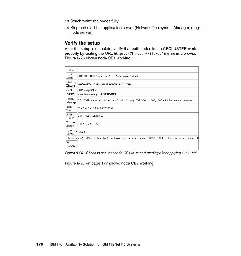
13.Synchronize the nodes fully.
14.Stop and start the application server (Network Deployment Manager, dmgr node server).
Verify the setup After the setup is complete, verify that both nodes in the CECLUSTER work properly by visiting the URL http://<CE node>/FileNet/Engine in a browser. Figure 8-26 shows node CE1 working.
Figure 8-26 Check to see that node CE1 is up and running after applying 4.0.1-004
Figure 8-27 on page 177 shows node CE2 working.
176 IBM High Availability Solution for IBM FileNet P8 Systems

Figure 8-27 Check to see that node CE2 is up and running after applying 4.0.1-004
Installing the Content Search Engine clientAfter the Content Engine cluster set is complete, we proceed with installing Content Search Engine (CSE) Client Updater on the Content Engine machines in the Content Engine cluster.
We apply the CSE updater patch 4.0.1-003 with the defaults. Figure 8-28 on page 178 shows the installation summary panel.
Note: When installing the CSE client on CE, it is not required that the CSE server is installed first. The CSE client installer can still be run on the CE (even if the remote CSE server is not installed yet), which installs the necessary client for CE to connect to CSE.
Chapter 8. Content Engine implementation 177
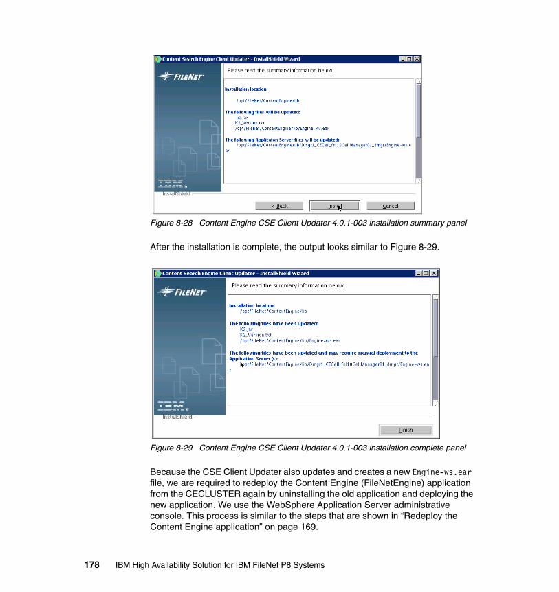
Figure 8-28 Content Engine CSE Client Updater 4.0.1-003 installation summary panel
After the installation is complete, the output looks similar to Figure 8-29.
Figure 8-29 Content Engine CSE Client Updater 4.0.1-003 installation complete panel
Because the CSE Client Updater also updates and creates a new Engine-ws.ear file, we are required to redeploy the Content Engine (FileNetEngine) application from the CECLUSTER again by uninstalling the old application and deploying the new application. We use the WebSphere Application Server administrative console. This process is similar to the steps that are shown in “Redeploy the Content Engine application” on page 169.
178 IBM High Availability Solution for IBM FileNet P8 Systems
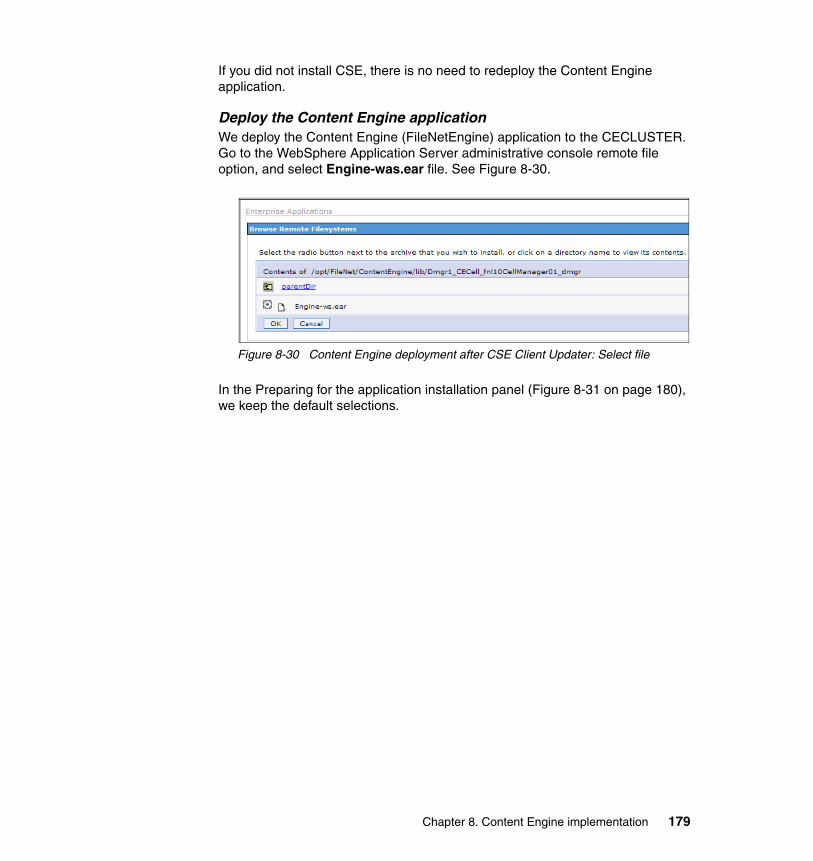
If you did not install CSE, there is no need to redeploy the Content Engine application.
Deploy the Content Engine application We deploy the Content Engine (FileNetEngine) application to the CECLUSTER. Go to the WebSphere Application Server administrative console remote file option, and select Engine-was.ear file. See Figure 8-30.
Figure 8-30 Content Engine deployment after CSE Client Updater: Select file
In the Preparing for the application installation panel (Figure 8-31 on page 180), we keep the default selections.
Chapter 8. Content Engine implementation 179
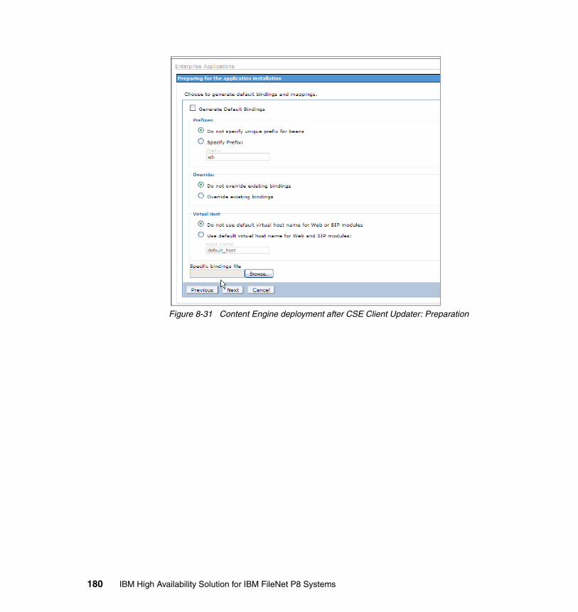
Figure 8-31 Content Engine deployment after CSE Client Updater: Preparation
180 IBM High Availability Solution for IBM FileNet P8 Systems
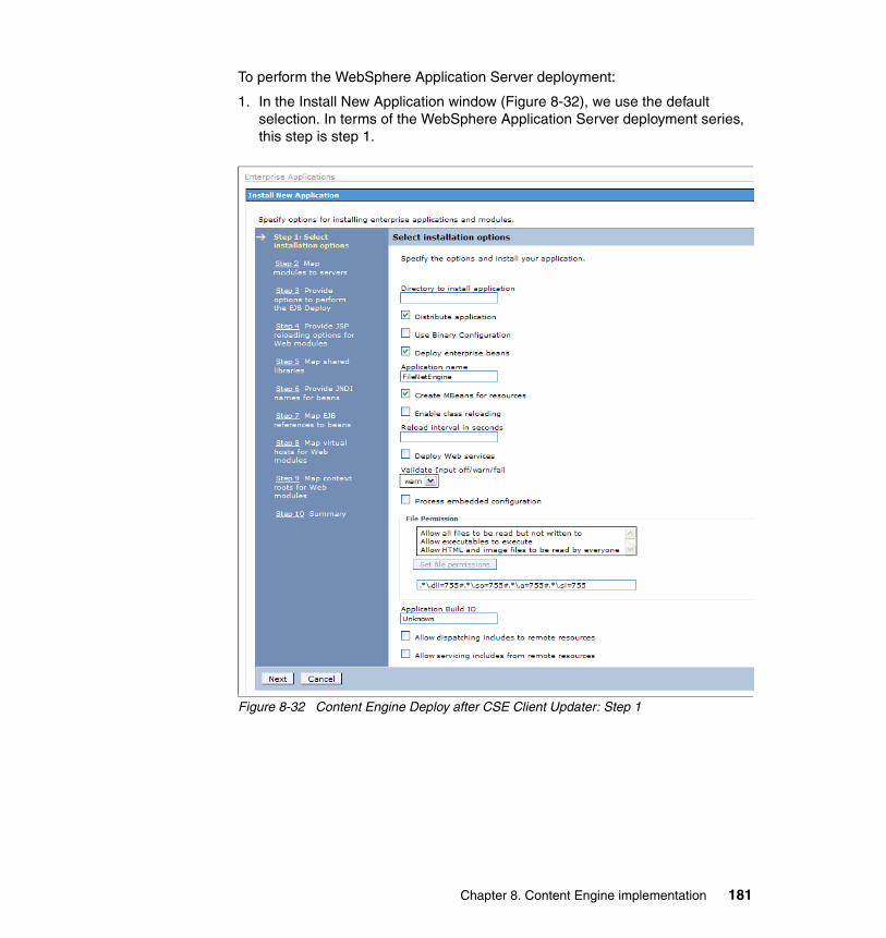
To perform the WebSphere Application Server deployment:
1. In the Install New Application window (Figure 8-32), we use the default selection. In terms of the WebSphere Application Server deployment series, this step is step 1.
Figure 8-32 Content Engine Deploy after CSE Client Updater: Step 1
Chapter 8. Content Engine implementation 181
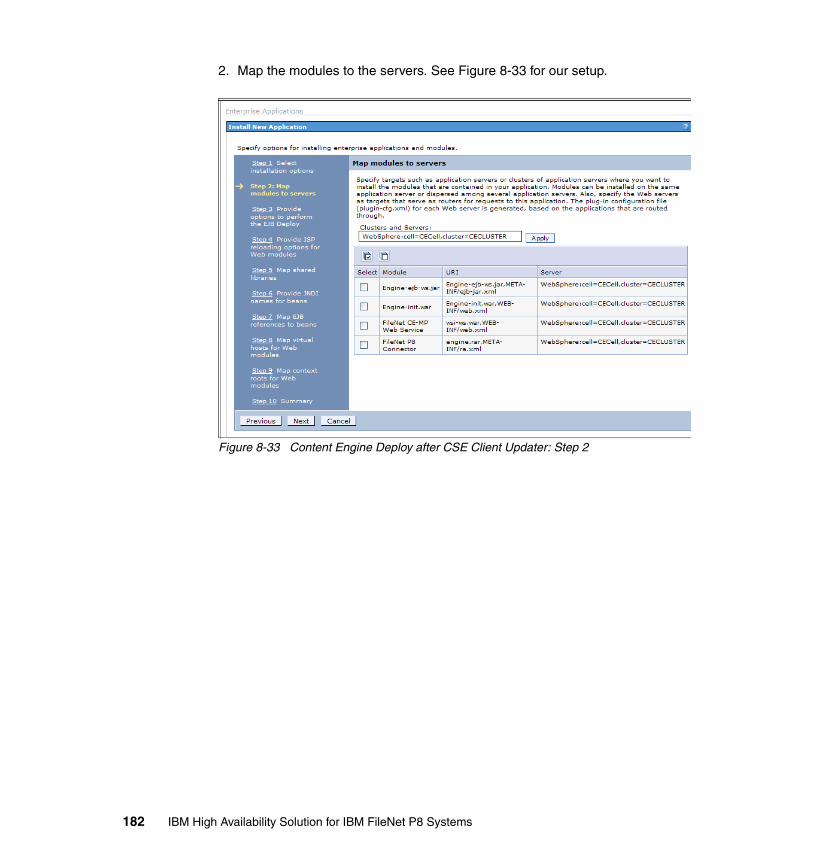
2. Map the modules to the servers. See Figure 8-33 for our setup.
Figure 8-33 Content Engine Deploy after CSE Client Updater: Step 2
182 IBM High Availability Solution for IBM FileNet P8 Systems
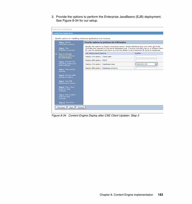
3. Provide the options to perform the Enterprise JavaBeans (EJB) deployment. See Figure 8-34 for our setup.
Figure 8-34 Content Engine Deploy after CSE Client Updater: Step 3
Chapter 8. Content Engine implementation 183
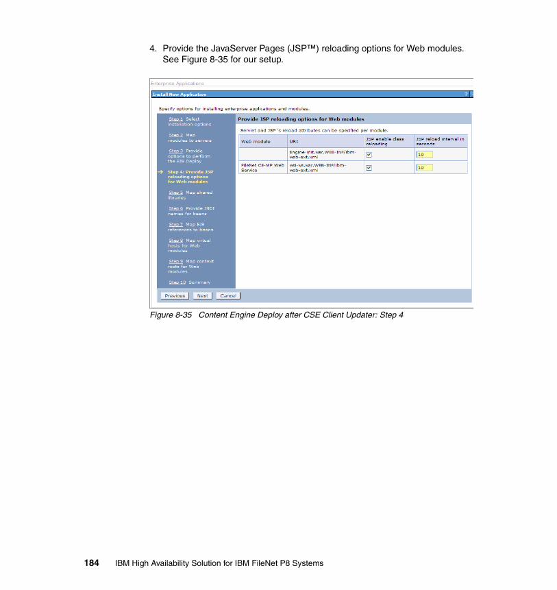
4. Provide the JavaServer Pages (JSP™) reloading options for Web modules. See Figure 8-35 for our setup.
Figure 8-35 Content Engine Deploy after CSE Client Updater: Step 4
184 IBM High Availability Solution for IBM FileNet P8 Systems
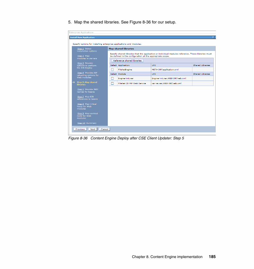
5. Map the shared libraries. See Figure 8-36 for our setup.
Figure 8-36 Content Engine Deploy after CSE Client Updater: Step 5
Chapter 8. Content Engine implementation 185
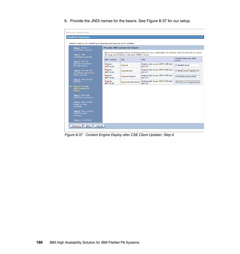
6. Provide the JNDI names for the beans. See Figure 8-37 for our setup.
Figure 8-37 Content Engine Deploy after CSE Client Updater: Step 6
186 IBM High Availability Solution for IBM FileNet P8 Systems
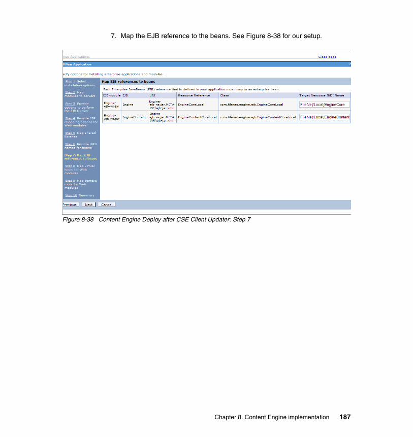
7. Map the EJB reference to the beans. See Figure 8-38 for our setup.
Figure 8-38 Content Engine Deploy after CSE Client Updater: Step 7
Chapter 8. Content Engine implementation 187
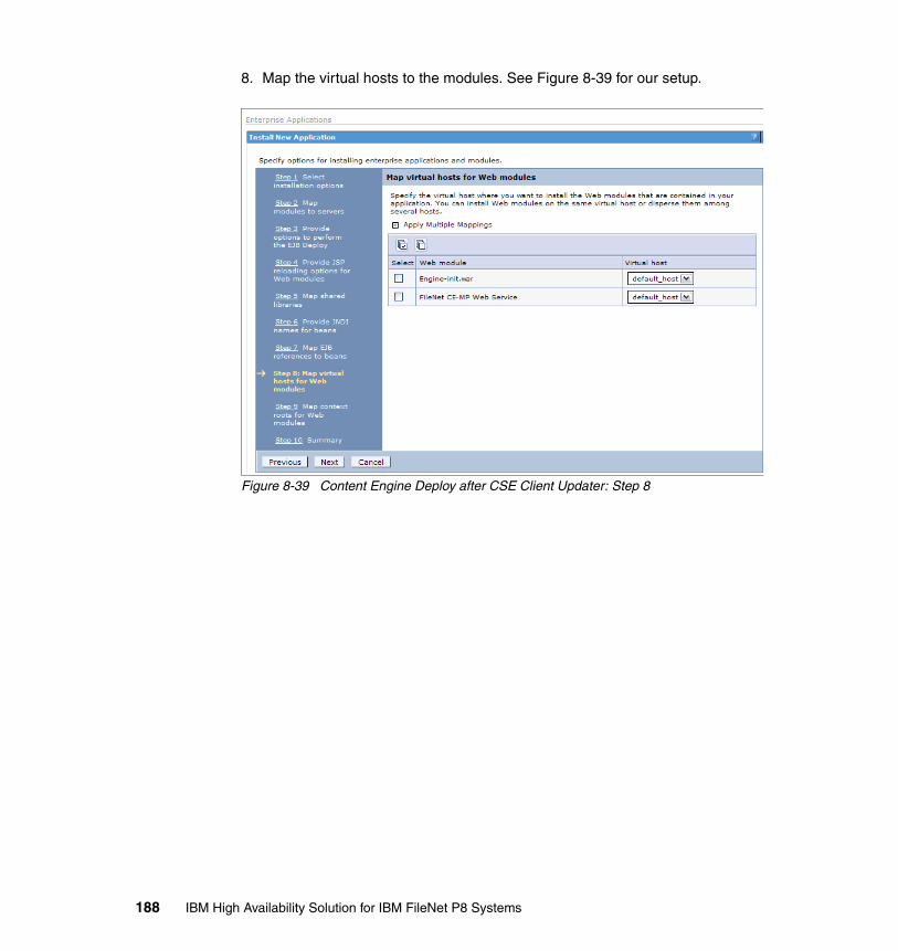
8. Map the virtual hosts to the modules. See Figure 8-39 for our setup.
Figure 8-39 Content Engine Deploy after CSE Client Updater: Step 8
188 IBM High Availability Solution for IBM FileNet P8 Systems
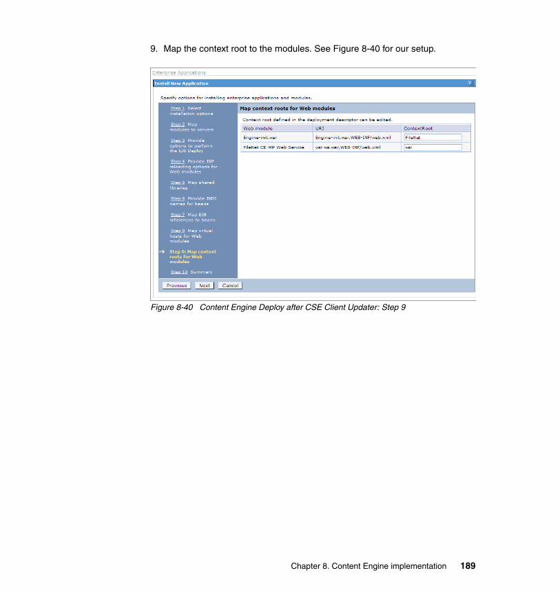
9. Map the context root to the modules. See Figure 8-40 for our setup.
Figure 8-40 Content Engine Deploy after CSE Client Updater: Step 9
Chapter 8. Content Engine implementation 189
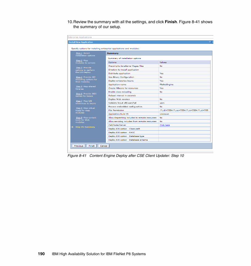
10.Review the summary with all the settings, and click Finish. Figure 8-41 shows the summary of our setup.
Figure 8-41 Content Engine Deploy after CSE Client Updater: Step 10
190 IBM High Availability Solution for IBM FileNet P8 Systems
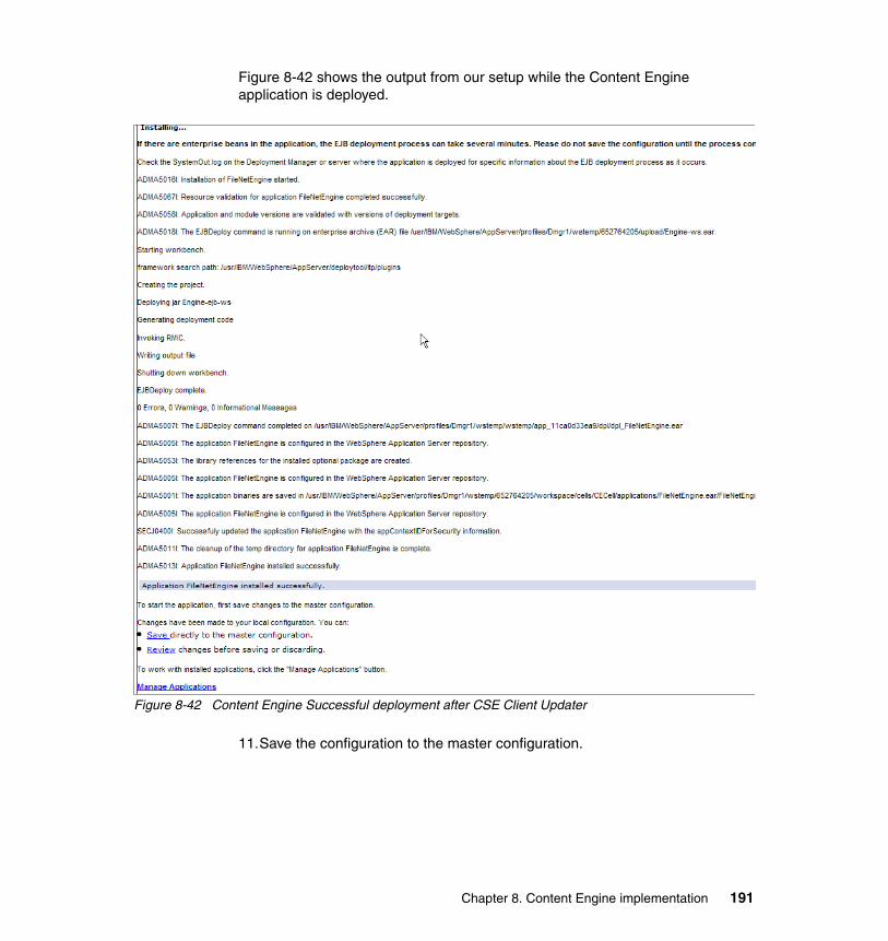
Figure 8-42 shows the output from our setup while the Content Engine application is deployed.
Figure 8-42 Content Engine Successful deployment after CSE Client Updater
11.Save the configuration to the master configuration.
Chapter 8. Content Engine implementation 191
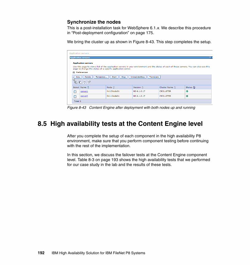
Synchronize the nodesThis is a post-installation task for WebSphere 6.1.x. We describe this procedure in “Post-deployment configuration” on page 175.
We bring the cluster up as shown in Figure 8-43. This step completes the setup.
Figure 8-43 Content Engine after deployment with both nodes up and running
8.5 High availability tests at the Content Engine level
After you complete the setup of each component in the high availability P8 environment, make sure that you perform component testing before continuing with the rest of the implementation.
In this section, we discuss the failover tests at the Content Engine component level. Table 8-3 on page 193 shows the high availability tests that we performed for our case study in the lab and the results of these tests.
192 IBM High Availability Solution for IBM FileNet P8 Systems

Table 8-3 Content Engine-level high availability test scenarios
8.5.1 Content Engine basic availability test
The basic test to see whether Content Engine is available is by going to the following URL:
http://9.30.188.91:19080/FileNet/Engine
The IP address used here must be the virtual IP address of Content Engine.
Use the load balancer console to show the Content Engine node’s status. In our case, we use the BIG-IP F5 as the load balancer. Figure 8-44 on page 194 shows the application status from the BIG-IP F5 console window (as it monitors).
Sr. no. Test Expected result Actual result
Test 1 Basic availability test: Test the Content Engine using the following URL:http://9.30.188.91:19080/FileNet/EngineNote, use the Content Engine virtual IP address for testing.
The URL works. Response is from either one of the Content Engine nodes.
See 8.5.1, “Content Engine basic availability test” on page 193.
Test 2 Node availability test 1: Test the Content Engine while Content Engine node 1 (CE1) is down.Use the previous test’s URL.
The URL works. Response is from CE2.
See 8.5.2, “Node availability test 1” on page 195.
Test 3 Node availability test 2: Test the Content Engine while Content Engine node 2 (CE2) is down.Use the same URL.
The URL works. Response is from CE1.
See 8.5.3, “Node availability test 2” on page 197.
Test 4 High Availability Test: Test the Content Engine with two simultaneous connections. Use the same URL.
The URL works.Responses are from both Content Engine nodes.
See 8.5.4, “Load balance test” on page 199.
Chapter 8. Content Engine implementation 193
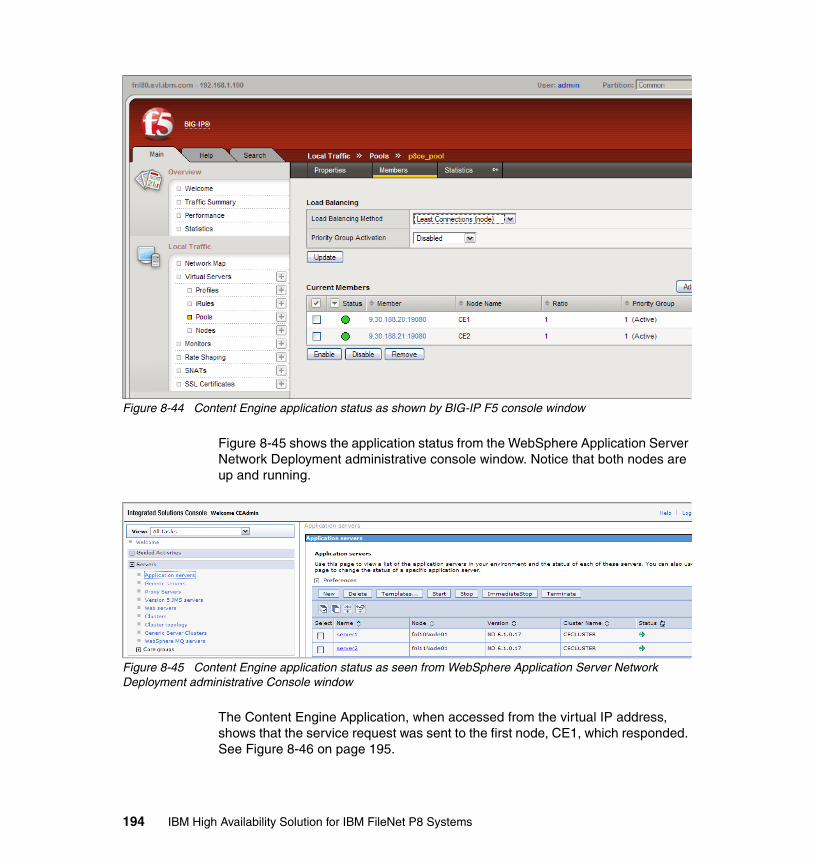
Figure 8-44 Content Engine application status as shown by BIG-IP F5 console window
Figure 8-45 shows the application status from the WebSphere Application Server Network Deployment administrative console window. Notice that both nodes are up and running.
Figure 8-45 Content Engine application status as seen from WebSphere Application Server Network Deployment administrative Console window
The Content Engine Application, when accessed from the virtual IP address, shows that the service request was sent to the first node, CE1, which responded. See Figure 8-46 on page 195.
194 IBM High Availability Solution for IBM FileNet P8 Systems

Figure 8-46 Response for the Content Engine application URL
8.5.2 Node availability test 1
In this test, we bring down one Content Engine node (CE1) and use the same Content Engine virtual IP address to see whether the URL is being serviced.
Figure 8-47 on page 196 from the WebSphere Application Server Network Deployment administrative console shows that node CE1 is down.
Chapter 8. Content Engine implementation 195
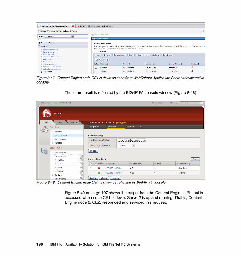
Figure 8-47 Content Engine node CE1 is down as seen from WebSphere Application Server administrative console
The same result is reflected by the BIG-IP F5 console window (Figure 8-48).
Figure 8-48 Content Engine node CE1 is down as reflected by BIG-IP F5 console
Figure 8-49 on page 197 shows the output from the Content Engine URL that is accessed when node CE1 is down. Server2 is up and running. That is, Content Engine node 2, CE2, responded and serviced this request.
196 IBM High Availability Solution for IBM FileNet P8 Systems
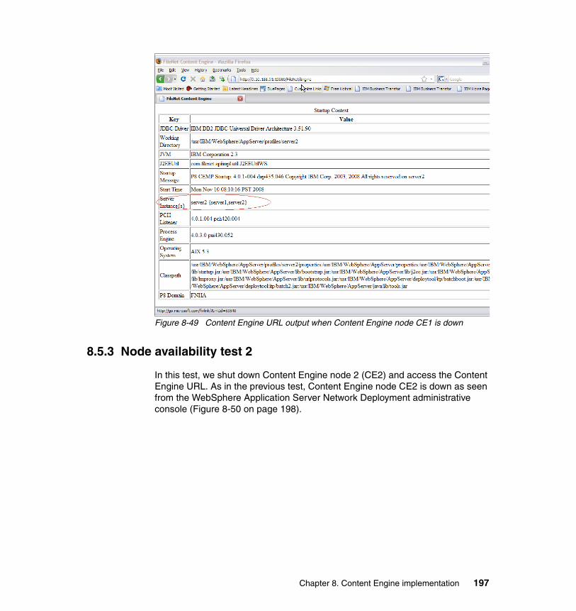
Figure 8-49 Content Engine URL output when Content Engine node CE1 is down
8.5.3 Node availability test 2
In this test, we shut down Content Engine node 2 (CE2) and access the Content Engine URL. As in the previous test, Content Engine node CE2 is down as seen from the WebSphere Application Server Network Deployment administrative console (Figure 8-50 on page 198).
Chapter 8. Content Engine implementation 197
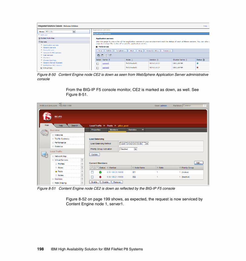
Figure 8-50 Content Engine node CE2 is down as seen from WebSphere Application Server administrative console
From the BIG-IP F5 console monitor, CE2 is marked as down, as well. See Figure 8-51.
Figure 8-51 Content Engine node CE2 is down as reflected by the BIG-IP F5 console
Figure 8-52 on page 199 shows, as expected, the request is now serviced by Content Engine node 1, server1.
198 IBM High Availability Solution for IBM FileNet P8 Systems
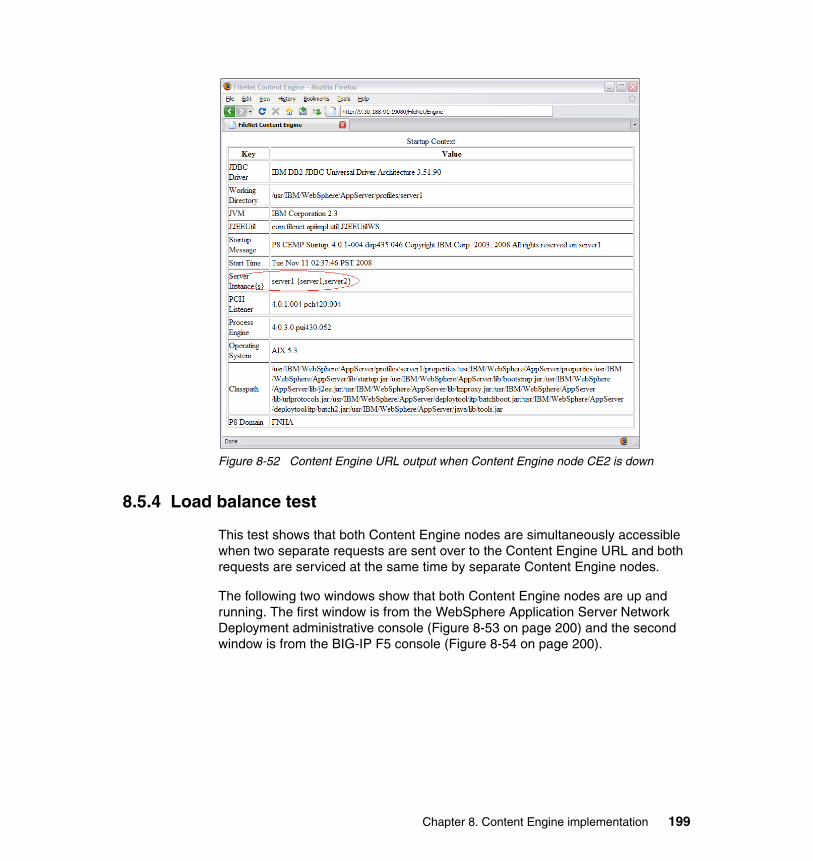
Figure 8-52 Content Engine URL output when Content Engine node CE2 is down
8.5.4 Load balance test
This test shows that both Content Engine nodes are simultaneously accessible when two separate requests are sent over to the Content Engine URL and both requests are serviced at the same time by separate Content Engine nodes.
The following two windows show that both Content Engine nodes are up and running. The first window is from the WebSphere Application Server Network Deployment administrative console (Figure 8-53 on page 200) and the second window is from the BIG-IP F5 console (Figure 8-54 on page 200).
Chapter 8. Content Engine implementation 199
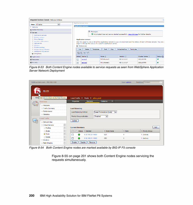
Figure 8-53 Both Content Engine nodes available to service requests as seen from WebSphere Application Server Network Deployment
Figure 8-54 Both Content Engine nodes are marked available by BIG-IP F5 console
Figure 8-55 on page 201 shows both Content Engine nodes servicing the requests simultaneously.
200 IBM High Availability Solution for IBM FileNet P8 Systems

Figure 8-55 Both Content Engine nodes servicing the requests simultaneously
Chapter 8. Content Engine implementation 201

202 IBM High Availability Solution for IBM FileNet P8 Systems

Chapter 9. Process Engine implementation
This chapter describes the high availability options for Process Engine and our case study setup in relation to it. We also describe the practical, step-by-step procedures that we use to implement high availability for Process Engine.
We discuss the following topics:
� Introduction� High Availability options for Process Engine� Design for the case study� Setup for active/active Process Engine cluster (farm)� High availability tests at the Process Engine level
9
© Copyright IBM Corp. 2009. All rights reserved. 203
9.1 Introduction
FileNet P8 Process Engine (PE) lets you create, modify, manage, analyze, and simulate business processes (also referred to as workflows). These workflows are performed by applications, enterprise users, and external users, such as partners and customers. It is critical to provide high availability for Process Engine in the overall high availability of the IBM FileNet P8 solution.
For an overview of Process Engine, refer to 2.3, “Process Engine” on page 26.
9.2 High Availability options for Process Engine
As Process Engine (PE) stores the information about the workflow process, when PE is unavailable, neither IBM FileNet P8 Application Engine (AE) nor IBM FileNet P8 Content Engine (CE) can retrieve any workflow process-related data. All the processes in the system remain at their current state until AE or CE can reconnect to PE and continue the work.
The aim of making PE highly available is to make it available to run and service the requests (from either AE or CE) even if one of the PEs in the farm or cluster is unavailable.
PE can be made highly available in one of two ways:
� Active/active cluster:
An active/active cluster (farm) is a configuration where multiple PE servers are available to service a request. Each machine in a highly available configuration is called a node. In an active/active cluster, in case a node goes down or is unavailable, the requests are routed automatically to the other available nodes. A hardware-based load balancer is needed for balancing the load that is sent to the nodes. Depending on the load balancer, the load can be sprayed on the nodes using various algorithms, such as round-robin and least connections.
� Active/passive cluster:
An active/passive cluster is a configuration where an active PE server is available to service client (AE or CE) requests. The passive node is running in a listening mode. The second node is always synchronized with the active node in terms of application configuration and application data. In the case of a failure in the active node, the passive node assumes the responsibility and becomes the active node. In this scenario, all the subsystems are defined as resources for the cluster that, in case of a node failure, fail over to the passive node. The cluster services are provided by operating system vendors, for
204 IBM High Availability Solution for IBM FileNet P8 Systems
example, IBM PowerHA for AIX (HACMP - formerly IBM High Availability Cluster Multi-Processing).
The application data is stored in a Process Engine database, which is also made available in a highly available mode in both scenarios.
9.3 Design for the case study
For our case study setup, we choose the recommended active/active cluster (farm) configuration for making the Process Engine highly available. There are two nodes running the Process Engines. Both nodes run the IBM AIX operating system.
All the PEs in a farm share the same database instance. The individual machines do not know about each other nor do they communicate in any way, except for isolated region initialization, transfer of configuration, and transfer of process definitions. That is, when a workflow process or a configuration is transferred, all of the machines in the farm are notified to update their configuration with the information of the newly transferred workflow process. The server, which can be any of the servers in the farm, that received the transfer remote procedure call (RPC) is the one that communicates with the other servers. It finds the other servers by looking at the database for the names and addresses of the other servers and then sends them a message (if they are active). Each server checks the database for a transfer in process when the server starts up.
All servers in the PE farm must have the same hardware word size and word boundaries, as well as they must have the same byte order (big-endian as opposed to little-endian).
Each machine in the PE farm is an exact replica of the other machines and, as such, is capable of carrying out all possible PE transactions. Additionally, each server in the farm is actively participating in handling the workload. Therefore, even if one of the PE machines in the farm goes down, all of the other machines continue to actively process work. Thus, the PE systems as a whole remain up as an active/active, highly available configuration.
All the servers in a PE farm can be managed from one Process Task Manager.
Figure 9-1 on page 206 shows the PE farm in an active/active mode.
Chapter 9. Process Engine implementation 205
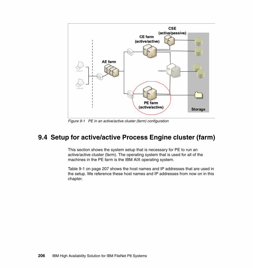
Figure 9-1 PE in an active/active cluster (farm) configuration
9.4 Setup for active/active Process Engine cluster (farm)
This section shows the system setup that is necessary for PE to run an active/active cluster (farm). The operating system that is used for all of the machines in the PE farm is the IBM AIX operating system.
Table 9-1 on page 207 shows the host names and IP addresses that are used in the setup. We reference these host names and IP addresses from now on in this chapter.
CE farm (active/active)
CE farm (active/active)
Client 1
Client N
StorageStorage
RDBMSRDBMS
PE farm(active/active)
PE farm(active/active)
CSE(active/passive)
CSE(active/passive)
AE farmAE farm
206 IBM High Availability Solution for IBM FileNet P8 Systems

Table 9-1 System setup summary
9.4.1 Procedure for PE active/active cluster (farm) setup
Most of these steps, both prerequisites and the actual installation steps, are the same steps that are described in IBM FileNet P8 4.0 Installation and Upgrade Guide, GC31-5488. We include them here for ease of reference and for the completeness of our setup. In certain cases, there are specific options that are used for creating the active/active PE farm.
The steps that we provide here are sequential in nature and need to be executed in order.
Installing and setting up the prerequisites The prerequisite installation includes installing DB2 client instances on the PE nodes, cataloging the database node and the database, creating the appropriate file systems, and creating raw partitions.
For our case study, we perform the following steps before installing PE:
1. Install the PE database.
For details, refer to Chapter 12, “DB2 implementation” on page 369.
2. Install the IBM DB2 Client instance on both nodes.
It is mandatory to install the DB2 Version 8 Client instance, even if the database server is DB2 Version 9.x. We use DB2 for Linux, UNIX and Windows Server Version 9.5 Fix Pack 1.
Node Host name IP address
CE1 fnl10.svl.ibm.com 9.30.188.20
CE2 fnl11.svl.ibm.com 9.30.188.21
AE1 fnl3.svl.ibm.com 9.30.188.13
AE2 fnl4.svl.ibm.com 9.30.188.14
PE1 fnl20.svl.ibm.com 9.30.188.30
PE2 fnl21.svl.ibm.com 9.30.188.31
P8CE (Content Engine virtual)
p8ce.svl.ibm.com 9.30.188.91
P8PE (PE virtual) P8PE.svl.ibm.com 9.30.188.92
Chapter 9. Process Engine implementation 207
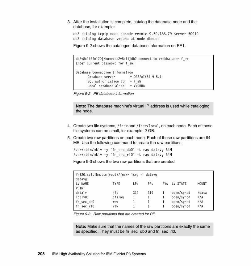
3. After the installation is complete, catalog the database node and the database, for example:
db2 catalog tcpip node dbnode remote 9.30.188.79 server 50010db2 catalog database vwdbha at node dbnode
Figure 9-2 shows the cataloged database information on PE1.
Figure 9-2 PE database information
4. Create two file systems, /fnsw and /fnsw/local, on each node. Each of these file systems can be small, for example, 2 GB.
5. Create two raw partitions on each node. Each of these raw partitions are 64 MB. Use the following command to create the raw partitions:
/usr/sbin/mklv -y ‘fn_sec_db0’ -t raw datavg 64M/usr/sbin/mklv -y ‘fn_sec_rl0’ -t raw datavg 64M
Figure 9-3 shows the two raw partitions that are created.
Figure 9-3 Raw partitions that are created for PE
db2v8cli@fnl20[/home/db2v8cli]db2 connect to vwdbha user f_swEnter current password for f_sw:
Database Connection InformationDatabase server = DB2/AIX64 9.5.1SQL authorization ID = F_SWLocal database alias = VWDBHA
Note: The database machine’s virtual IP address is used while cataloging the node.
fnl20.svl.ibm.com(root)/fnsw> lsvg -l datavgdatavg:LV NAME TYPE LPs PPs PVs LV STATE MOUNT POINTdatalv jfs 319 319 1 open/syncd /dataloglv01 jfslog 1 1 1 open/syncd N/Afn_sec_db0 raw 1 1 1 open/syncd N/Afn_sec_rl0 raw 1 1 1 open/syncd N/A
Note: Make sure that the names of the raw partitions are exactly the same as specified. They must be fn_sec_db0 and fn_sec_rl0.
208 IBM High Availability Solution for IBM FileNet P8 Systems
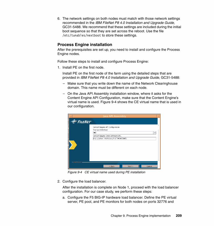
6. The network settings on both nodes must match with those network settings recommended in the IBM FileNet P8 4.0 Installation and Upgrade Guide, GC31-5488. We recommend that these settings are included during the initial boot sequence so that they are set across the reboot. Use the file /etc/tunables/nextboot to store these settings.
Process Engine installationAfter the prerequisites are set up, you need to install and configure the Process Engine nodes.
Follow these steps to install and configure Process Engine:
1. Install PE on the first node.
Install PE on the first node of the farm using the detailed steps that are provided in IBM FileNet P8 4.0 Installation and Upgrade Guide, GC31-5488:
– Make sure that you write down the name of the Network Clearinghouse domain. This name must be different on each node.
– On the Java API Assembly installation window, where it asks for the Content Engine API Configuration, make sure that the Content Engine’s virtual name is used. Figure 9-4 shows the CE virtual name that is used in our configuration.
Figure 9-4 CE virtual name used during PE installation
2. Configure the load balancer.
After the installation is complete on Node 1, proceed with the load balancer configuration. For our case study, we perform these steps:
a. Configure the F5 BIG-IP hardware load balancer. Define the PE virtual server, PE pool, and PE monitors for both nodes on ports 32776 and
Chapter 9. Process Engine implementation 209
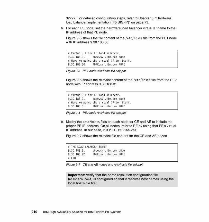
32777. For detailed configuration steps, refer to Chapter 5, “Hardware load balancer implementation (F5 BIG-IP)” on page 73.
b. For each PE node, set the hardware load balancer virtual IP name to the IP address of that PE node.
Figure 9-5 shows the file content of the /etc/hosts file from the PE1 node with IP address 9.30.188.30.
Figure 9-5 PE1 node /etc/hosts file snippet
Figure 9-6 shows the relevant content of the /etc/hosts file from the PE2 node with IP address 9.30.188.31.
Figure 9-6 PE2 node /etc/hosts file snippet
c. Modify the /etc/hosts files on each node for CE and AE to include the proper PE IP address. On all nodes, refer to PE by using that PE’s virtual IP address. In our case, it is P8PE.svl.ibm.com.
Figure 9-7 shows the relevant file content for the CE and AE nodes.
Figure 9-7 CE and AE nodes and /etc/hosts file snippet
# Virtual IP for F5 load balancer.9.30.188.91 p8ce.svl.ibm.com p8ce# Here we point the virtual IP to itself.9.30.188.30 P8PE.svl.ibm.com P8PE
# Virtual IP for F5 load balancer.9.30.188.91 p8ce.svl.ibm.com p8ce# Here we point the virtual IP to itself.9.30.188.31 P8PE.svl.ibm.com P8PE
# THE LOAD BALANCER SETUP9.30.188.91 p8ce.svl.ibm.com p8ce9.30.188.92 P8PE.svl.ibm.com P8PE# END
Important: Verify that the name resolution configuration file (nsswitch.conf) is configured so that it resolves host names using the local host’s file first.
210 IBM High Availability Solution for IBM FileNet P8 Systems
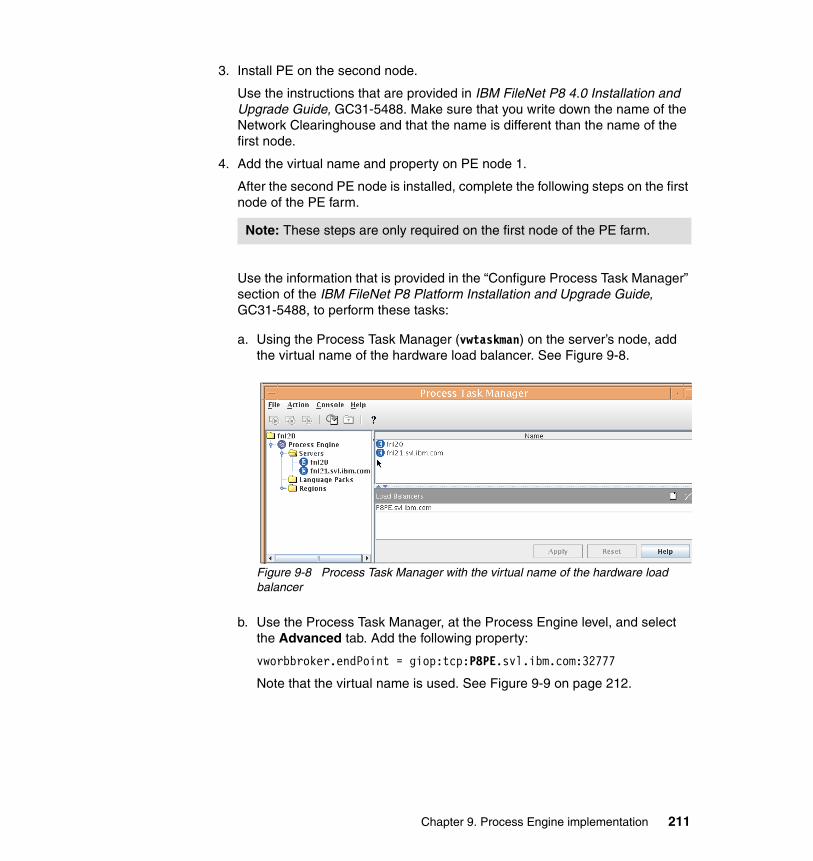
3. Install PE on the second node.
Use the instructions that are provided in IBM FileNet P8 4.0 Installation and Upgrade Guide, GC31-5488. Make sure that you write down the name of the Network Clearinghouse and that the name is different than the name of the first node.
4. Add the virtual name and property on PE node 1.
After the second PE node is installed, complete the following steps on the first node of the PE farm.
Use the information that is provided in the “Configure Process Task Manager” section of the IBM FileNet P8 Platform Installation and Upgrade Guide, GC31-5488, to perform these tasks:
a. Using the Process Task Manager (vwtaskman) on the server’s node, add the virtual name of the hardware load balancer. See Figure 9-8.
Figure 9-8 Process Task Manager with the virtual name of the hardware load balancer
b. Use the Process Task Manager, at the Process Engine level, and select the Advanced tab. Add the following property:
vworbbroker.endPoint = giop:tcp:P8PE.svl.ibm.com:32777
Note that the virtual name is used. See Figure 9-9 on page 212.
Note: These steps are only required on the first node of the PE farm.
Chapter 9. Process Engine implementation 211
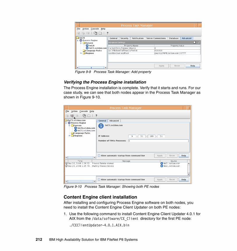
Figure 9-9 Process Task Manager: Add property
Verifying the Process Engine installationThe Process Engine installation is complete. Verify that it starts and runs. For our case study, we can see that both nodes appear in the Process Task Manager as shown in Figure 9-10.
Figure 9-10 Process Task Manager: Showing both PE nodes
Content Engine client installationAfter installing and configuring Process Engine software on both nodes, you need to install the Content Engine Client Updater on both PE nodes:
1. Use the following command to install Content Engine Client Updater 4.0.1 for AIX from the /data/software/CE_Client directory for the first PE node:
./CEClientUpdater-4.0.1.AIX.bin
212 IBM High Availability Solution for IBM FileNet P8 Systems
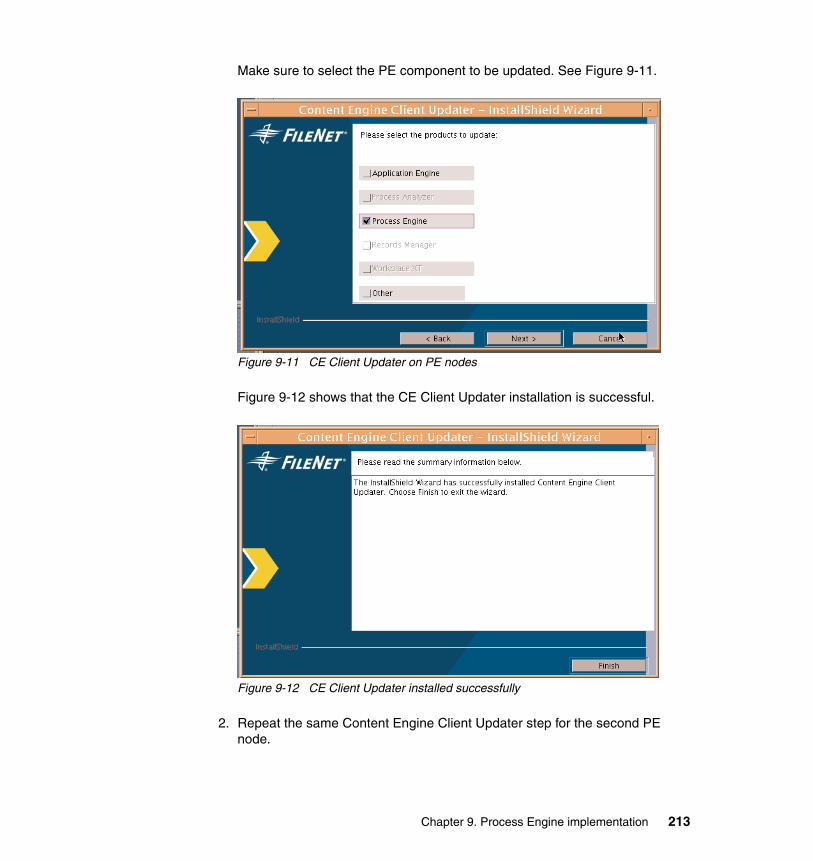
Make sure to select the PE component to be updated. See Figure 9-11.
Figure 9-11 CE Client Updater on PE nodes
Figure 9-12 shows that the CE Client Updater installation is successful.
Figure 9-12 CE Client Updater installed successfully
2. Repeat the same Content Engine Client Updater step for the second PE node.
Chapter 9. Process Engine implementation 213

After the CE Client Updater is successfully installed, the installation for PE is complete.
9.5 High availability tests at the Process Engine level
After you complete the setup of each component in the high availability P8 environment, make sure that you perform component testing before continuing with the rest of the implementation.
In this section, we discuss the failover tests at the Process Engine component level. Table 9-2 shows the high availability tests that we performed for our case study in the lab and the results of these tests.
Table 9-2 Process Engine-level high availability test scenarios
9.5.1 Process Engine basic availability test
To conduct this test, we look at the console of the F5 load balancer. The F5 load balancer monitors the nodes in each pool. If it does not find the node responsive,
Test scenario number
Test Expected result Actual result
Test 1 Basic availability test: Test the Process Engine using the following URL:http://9.30.188.92:32776/IOR/pingNote: Use the Process Engine virtual IP address for testing.
The URL works.Response is from either of the Process Engine nodes.
See 9.5.1, “Process Engine basic availability test” on page 214.
Test 2 Node availability test 1: Test the Process Engine while PE1 is down.Use the same URL as test 1.
The URL works.Response is from PE2.
See 9.5.2, “Node availability test 1” on page 216.
Test 3 Node availability test 2: Test the Process Engine while PE2 is down.Use the same URL as test 1.
The URL works.Response is from PE1.
See 9.5.3, “Node availability test 2” on page 217.
Test 4 High Availability Test: Test the Process Engine with two simultaneous connections. Use the same URL as test 1.
The URL works.Responses are from both PE nodes.
See 9.5.4, “High availability test” on page 218.
214 IBM High Availability Solution for IBM FileNet P8 Systems
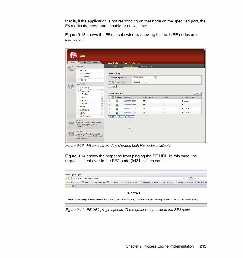
that is, if the application is not responding on that node on the specified port, the F5 marks the node unreachable or unavailable.
Figure 9-13 shows the F5 console window showing that both PE nodes are available.
Figure 9-13 F5 console window showing both PE nodes available
Figure 9-14 shows the response from pinging the PE URL. In this case, the request is sent over to the PE2 node (fnl21.svl.ibm.com).
Figure 9-14 PE URL ping response: The request is sent over to the PE2 node
Chapter 9. Process Engine implementation 215
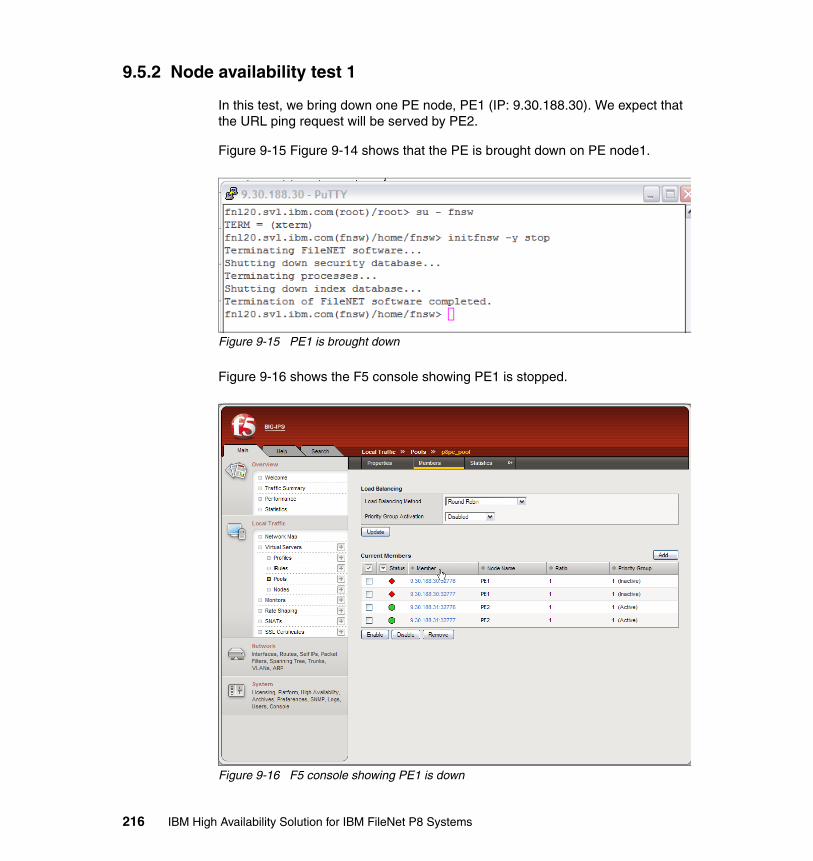
9.5.2 Node availability test 1
In this test, we bring down one PE node, PE1 (IP: 9.30.188.30). We expect that the URL ping request will be served by PE2.
Figure 9-15 Figure 9-14 shows that the PE is brought down on PE node1.
Figure 9-15 PE1 is brought down
Figure 9-16 shows the F5 console showing PE1 is stopped.
Figure 9-16 F5 console showing PE1 is down
216 IBM High Availability Solution for IBM FileNet P8 Systems
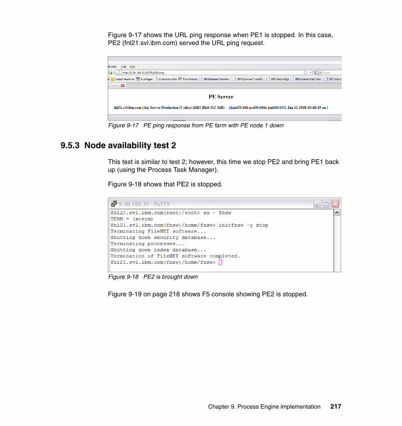
Figure 9-17 shows the URL ping response when PE1 is stopped. In this case, PE2 (fnl21.svl.ibm.com) served the URL ping request.
Figure 9-17 PE ping response from PE farm with PE node 1 down
9.5.3 Node availability test 2
This test is similar to test 2; however, this time we stop PE2 and bring PE1 back up (using the Process Task Manager).
Figure 9-18 shows that PE2 is stopped.
Figure 9-18 PE2 is brought down
Figure 9-19 on page 218 shows F5 console showing PE2 is stopped.
Chapter 9. Process Engine implementation 217
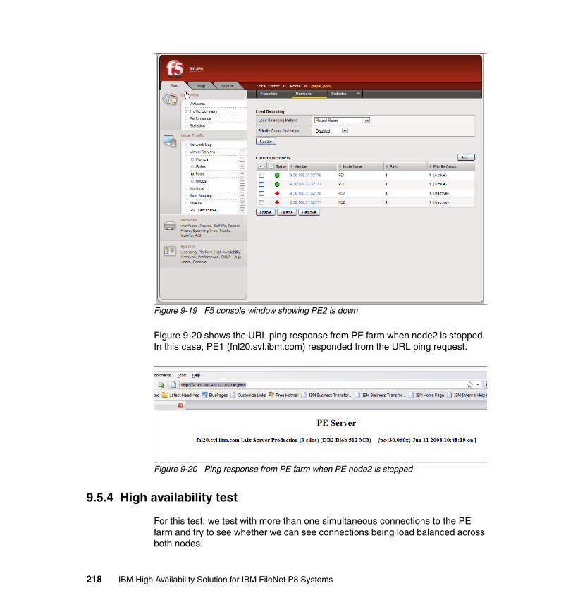
Figure 9-19 F5 console window showing PE2 is down
Figure 9-20 shows the URL ping response from PE farm when node2 is stopped. In this case, PE1 (fnl20.svl.ibm.com) responded from the URL ping request.
Figure 9-20 Ping response from PE farm when PE node2 is stopped
9.5.4 High availability test
For this test, we test with more than one simultaneous connections to the PE farm and try to see whether we can see connections being load balanced across both nodes.
218 IBM High Availability Solution for IBM FileNet P8 Systems
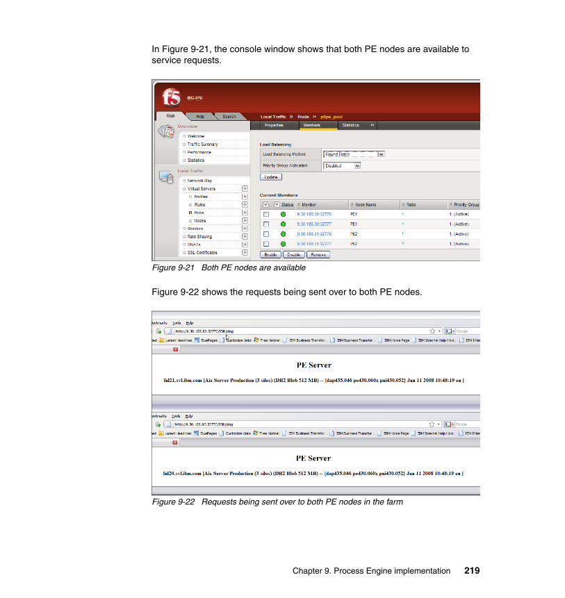
In Figure 9-21, the console window shows that both PE nodes are available to service requests.
Figure 9-21 Both PE nodes are available
Figure 9-22 shows the requests being sent over to both PE nodes.
Figure 9-22 Requests being sent over to both PE nodes in the farm
Chapter 9. Process Engine implementation 219

220 IBM High Availability Solution for IBM FileNet P8 Systems
Chapter 10. Content Search Engine implementation
This chapter describes a Content Search Engine (CSE) high availability strategy, our case study installation, and the practical, step-by-step, procedures that we use to implement the solution. In addition, we also describe updating the Content Engine server farm to use a highly available Content Search Engine.
We discuss the following topics:
� Introduction� Content Search Engine high availability strategy� Design for the case study� Installing and configuring the CSE components� High availability tests at the CSE level� Troubleshooting the Content Search Engine
10
© Copyright IBM Corp. 2009. All rights reserved. 221
10.1 Introduction
The IBM FileNet P8 platform relies on Autonomy’s K2 Enterprise technology for its content-based retrieval (CBR) functionality. This functionality is also referred to as the Content Search Engine, which is not to be confused with the IBM FileNet P8 Content Engine.
The K2 Enterprise Search Engine’s main function is to search, classify, and personalize large bodies of enterprise information for content-based search capabilities. Indexing is the process of ingesting and storing content (including CBR-enabled string properties of the document and any annotations) and building the appropriate data structures that support the querying of that content. To accomplish this task, Content Engine (CE) servers send indexing requests to the Content Search Engine, which, in turn, stores indexing data in collections for a particular object store. A collection is a separate file system that stores the references to all indexed documents and a list of all words contained within the text of the documents. In general, collections are much smaller than the total size of the documents that they represent.
For CBR-enabled objects, the indexing is performed asynchronously in batches when the objects are added to the object store. Therefore, newly added content is not immediately available for searches, and users can experience a delay in time before the documents can be searched through CBR.
All FileNet P8 clients, such as Workplace, communicate with the Content Search Engine through Content Engine, which manages the search operations and the creation and deletion of indexes.
The K2 Getting Started Guide Version 6.0 is available at this Web site:
http://www.sassafras.com/hrl/6.0/upgrade.html
This guide describes the K2 Distributed Deployment brokered architecture concepts, such as parallel querying, failover, and collection mirroring.
Figure 10-1 on page 223 illustrates a typical P8 core environment with the CSE component. The CSE configuration described in this chapter has all of the K2 services running on the same logical partition (LPAR).
Note: Autonomy refers to the various Content Search Engine services as servers.
222 IBM High Availability Solution for IBM FileNet P8 Systems
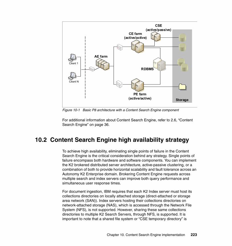
Figure 10-1 Basic P8 architecture with a Content Search Engine component
For additional information about Content Search Engine, refer to 2.6, “Content Search Engine” on page 36.
10.2 Content Search Engine high availability strategy
To achieve high availability, eliminating single points of failure in the Content Search Engine is the critical consideration behind any strategy. Single points of failure encompass both hardware and software components. You can implement the K2 brokered distributed server architecture, active-passive clustering, or a combination of both to provide horizontal scalability and fault tolerance across an Autonomy K2 Enterprise domain. Brokering Content Engine requests across multiple search and index servers can improve both query performance and simultaneous user response times.
For document ingestion, IBM requires that each K2 Index server must host its collections directories on locally attached storage (direct-attached or storage area network (SAN)). Index servers hosting their collections directories on network-attached storage (NAS), which is accessed through the Network File System (NFS), is not supported. However, sharing these same collections directories to multiple K2 Search Servers, through NFS, is supported. It is important to note that a shared file system or “CSE temporary directory” is
StorageStoragePE farm
(active/active)
CE farm(active/active)
AE farm
CSE(active/passive)
Client N
Client 1
RDBMS
Chapter 10. Content Search Engine implementation 223

required for CSE. Both the Content Engine (all nodes within the farm) and Content Search Engine servers must have access to this file system. As the CSE indexes documents, temporary files are created as content is passed from the Content Engine to Content Search Engine.
The Autonomy K2 domain supporting P8 is controlled by a single instance of the K2 Master Administration server. The Master Administration Server manages communications across the K2 domain, creates new collections directories as needed, and is used to perform ongoing administration. This service can only run on a single host and, thus, constitutes a single point of failure in the system. Therefore, this component must be configured in an active/passive clustered configuration.
10.3 Design for the case study
For our case study setup, we use an active/passive IBM PowerHA for AIX (HACMP - formerly IBM High Availability Cluster Multi-Processing) cluster configuration for making the Content Search Engine highly available. Two nodes, running identical versions of the IBM AIX operating system, are used to configure an active/passive cluster. Only the currently active node runs the CSE software, providing all the K2 services to the Content Engine farm.
Figure 10-2 on page 225 illustrates how the CSE cluster and CE farm are configured. The K2 Dispatcher process can only run on a single Content Engine server.
Note: If the machine hosting the K2 Master Administration Server stops responding, or the Master Administration Server is otherwise unavailable, new content can still be ingested by the P8 Content Engine. When the Master Administration Server becomes available again, indexing operations resume automatically.
The exception to this rule is a situation where a collection directory is full and a new collection ID cannot be assigned. In this case, new documents cannot be added to the CE. The CE running the K2 Dispatcher Queue logs errors while the CSE is down.
224 IBM High Availability Solution for IBM FileNet P8 Systems
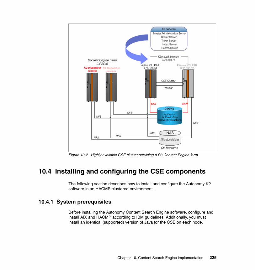
Figure 10-2 Highly available CSE cluster servicing a P8 Content Engine farm
10.4 Installing and configuring the CSE components
The following section describes how to install and configure the Autonomy K2 software in an HACMP clustered environment.
10.4.1 System prerequisites
Before installing the Autonomy Content Search Engine software, configure and install AIX and HACMP according to IBM guidelines. Additionally, you must install an identical (supported) version of Java for the CSE on each node.
Chapter 10. Content Search Engine implementation 225

Run the following commands on each node to ensure that the operating systems and HACMP/Java file set levels are identical:
oslevellslpp -L *cluster.*lslpp -L *Java*
The Content Engine servers are considered as K2 clients of the Autonomy K2 Master Server. The P8 Content Engine servers communicate directly with the K2 Broker server as a K2 Java API client. This communication uses an AIX user account to serve as the security link between the two systems. The K2 users and group have to be created on both nodes of the CSE cluster, and it is important to keep the K2 user and group IDs the same across all of the CSE servers.
For our use case configuration, we also created the K2 users and group on each Content Engine server. We keep the K2 user and group IDs the same across all of the servers.
In general, this uniformity is not a requirement as long as you configure the Content Engine’s Verity Domain Configuration tab with the correct user name and password for the K2 user on Content Search Engine. You must also make sure that the NFS permissions on the shared file system (the Content Search Engine’s temporary directory) allow access to both Content Engine and Content Search Engine.
File system creationBefore installing the CSE software, you must create the file systems. You must create these file systems in the shared volume group that will be controlled by HACMP.
For our case study, we create a shared volume group called csevg. Figure 10-3 shows the logical volumes and file systems that are contained inside the csevg shared volume group.
Figure 10-3 List logical volume groups
root@fnl41:/opt/verity>lsvg -l csevgcsevg:LV NAME TYPE LPs PPs PVs LV STATE MOUNT POINTcseloglv jfs2log 1 1 1 open/syncd N/Acsedata1lv jfs2 80 80 1 open/syncd /opt/verity/collectionscsedata2lv jfs2 16 16 1 open/syncd /opt/veritycsedata3lv jfs2 16 16 1 open/syncd /opt/verity/tmp
226 IBM High Availability Solution for IBM FileNet P8 Systems

Virtual IP address and host name creationCreate a virtual IP address and corresponding host name for the Content Search Engine. Update the local /etc/hosts file on both nodes of the cluster and on all Content Engine servers.
Figure 10-4 shows the CSE name (k2cse.svl.ibm.com) and IP address as configured in the /etc/hosts file on the case study servers.
Figure 10-4 Content of the /etc/hosts file
Table 10-1 on page 228 lists the configuration attributes, which are used in our case study, for the active/passive Content Search Engine cluster.
Tip: Make sure that the default system umask is set to 022 before creating the underlying mount points and mounting the file systems. If the default umask is not set to 022, the K2usr account will experience permission problems when attempting to access the mounted file systems.
# more /etc/hosts#CSE - P8 - service address - pub net 9.30.188.0/249.30.188.77 k2cse.svl.ibm.com k2cse
9.30.188.51 fnl41.svl.ibm.com fnl41 c210.0.3.51 fnl41-hs03.svl.ibm.com fnl41-hs0310.0.4.51 fnl41-hs04.svl.ibm.com fnl41-hs0410.0.5.51 fnl41-hs05.svl.ibm.com fnl41-hs0510.254.240.51 fnl41-hmcp.svl.ibm.com fnl41-hmcp#9.30.188.52 fnl42.svl.ibm.com fnl42 c310.0.3.52 fnl42-hs03.svl.ibm.com fnl42-hs0310.0.4.52 fnl42-hs04.svl.ibm.com fnl42-hs0410.0.5.52 fnl42-hs05.svl.ibm.com fnl42-hs0510.254.240.52 fnl42-hmcp.svl.ibm.com fnl42-hmcp
Chapter 10. Content Search Engine implementation 227
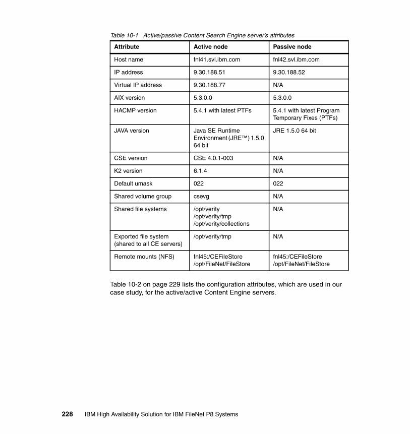
Table 10-1 Active/passive Content Search Engine server’s attributes
Table 10-2 on page 229 lists the configuration attributes, which are used in our case study, for the active/active Content Engine servers.
Attribute Active node Passive node
Host name fnl41.svl.ibm.com fnl42.svl.ibm.com
IP address 9.30.188.51 9.30.188.52
Virtual IP address 9.30.188.77 N/A
AIX version 5.3.0.0 5.3.0.0
HACMP version 5.4.1 with latest PTFs 5.4.1 with latest Program Temporary Fixes (PTFs)
JAVA version Java SE Runtime Environment (JRE™) 1.5.0 64 bit
JRE 1.5.0 64 bit
CSE version CSE 4.0.1-003 N/A
K2 version 6.1.4 N/A
Default umask 022 022
Shared volume group csevg N/A
Shared file systems /opt/verity/opt/verity/tmp/opt/verity/collections
N/A
Exported file system(shared to all CE servers)
/opt/verity/tmp N/A
Remote mounts (NFS) fnl45:/CEFileStore/opt/FileNet/FileStore
fnl45:/CEFileStore/opt/FileNet/FileStore
228 IBM High Availability Solution for IBM FileNet P8 Systems
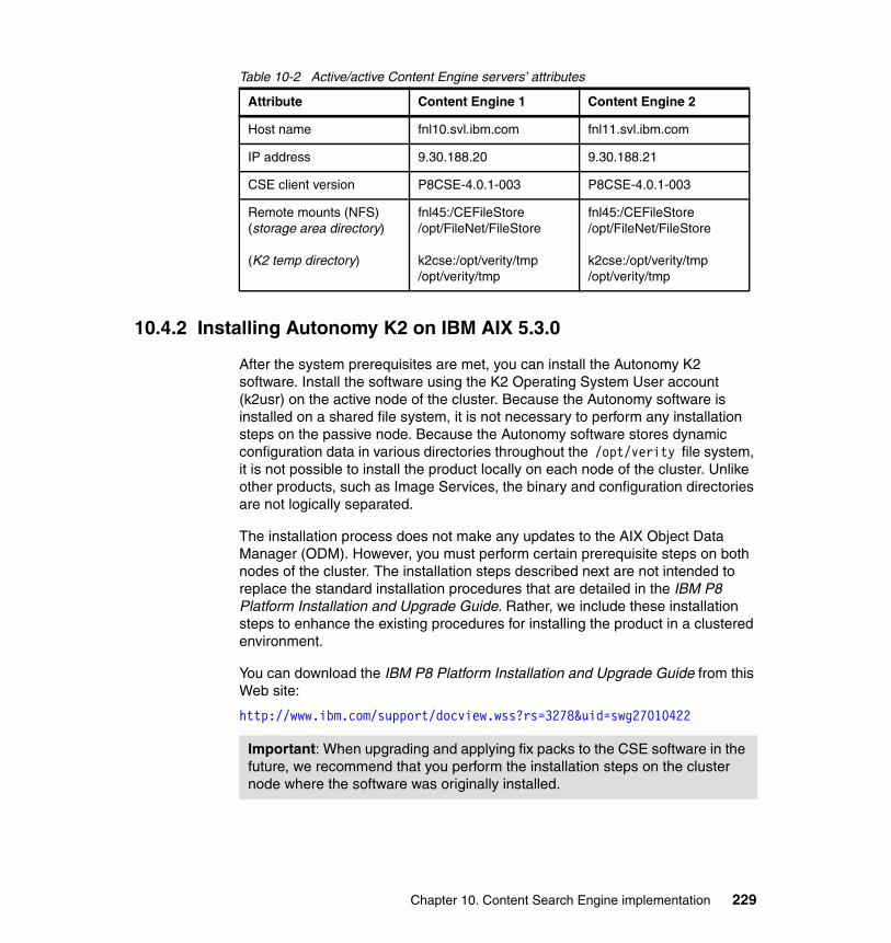
Table 10-2 Active/active Content Engine servers’ attributes
10.4.2 Installing Autonomy K2 on IBM AIX 5.3.0
After the system prerequisites are met, you can install the Autonomy K2 software. Install the software using the K2 Operating System User account (k2usr) on the active node of the cluster. Because the Autonomy software is installed on a shared file system, it is not necessary to perform any installation steps on the passive node. Because the Autonomy software stores dynamic configuration data in various directories throughout the /opt/verity file system, it is not possible to install the product locally on each node of the cluster. Unlike other products, such as Image Services, the binary and configuration directories are not logically separated.
The installation process does not make any updates to the AIX Object Data Manager (ODM). However, you must perform certain prerequisite steps on both nodes of the cluster. The installation steps described next are not intended to replace the standard installation procedures that are detailed in the IBM P8 Platform Installation and Upgrade Guide. Rather, we include these installation steps to enhance the existing procedures for installing the product in a clustered environment.
You can download the IBM P8 Platform Installation and Upgrade Guide from this Web site:
http://www.ibm.com/support/docview.wss?rs=3278&uid=swg27010422
Attribute Content Engine 1 Content Engine 2
Host name fnl10.svl.ibm.com fnl11.svl.ibm.com
IP address 9.30.188.20 9.30.188.21
CSE client version P8CSE-4.0.1-003 P8CSE-4.0.1-003
Remote mounts (NFS)(storage area directory)
(K2 temp directory)
fnl45:/CEFileStore/opt/FileNet/FileStore
k2cse:/opt/verity/tmp/opt/verity/tmp
fnl45:/CEFileStore/opt/FileNet/FileStore
k2cse:/opt/verity/tmp/opt/verity/tmp
Important: When upgrading and applying fix packs to the CSE software in the future, we recommend that you perform the installation steps on the cluster node where the software was originally installed.
Chapter 10. Content Search Engine implementation 229

Follow these steps to install Autonomy K2 software:
1. Create the following user accounts and group on both nodes of the cluster:
– K2 Operating System User– K2 Security User– K2 Security Group
You must create the exact same user on both nodes. Create the same password for the same user account on each node.
For our case study, we create these users and this group:
– k2usr (for K2 Operating System User)– k2sec (for K2 Security User)– k2secgrp (for K2 Security Group)
Verify that the user accounts are identical by comparing the outputs of the following command:
# grep k2usr /etc/passwdk2usr:!:1000:214::/home/k2usr:/usr/bin/ksh# grep k2sec /etc/passwdk2sec:!:1001:214::/home/k2sec:/usr/bin/ksh# grep k2secgrp /etc/groupk2secgrp:!:214:k2usr,k2sec
2. Ensure that the shared file systems are mounted on the active node and that they have the following ownership and permissions:
# df -k | grep verity/dev/csedata2lv 4194304 2742488 35% 17351 6% /opt/verity/dev/csedata1lv 20971520 11733584 45% 126 1% /opt/verity/collections/dev/csedata3lv 4194304 4192936 1% 14 1% /opt/verity/tmp# ls -l /opt | grep veritydrwxr-xr-x 8 k2usr k2secgrp 4096 Oct 02 16:50 verity# ls -l /opt/veritydrwxrwxr-x 5 k2usr k2secgrp 4096 Oct 10 08:49 collectionsdrwxr-xr-x 2 k2usr k2secgrp 256 Sep 19 14:08 lost+founddrwxrwxr-x 6 k2usr k2secgrp 256 Oct 09 16:44 tmp
Tip: When creating the logical volume for /opt/verity/collections, refer to the Autonomy K2 documentation for proper sizing and capacity planning considerations.
230 IBM High Availability Solution for IBM FileNet P8 Systems

3. Install Content Search Engine Version 4.0.0 general availability (GA) as described in the IBM P8 Platform Installation and Upgrade Guide:
a. Execute Task 11, “Install and Configure Content Search Engine” (see the AIX platform section of the IBM P8 Platform Installation and Upgrade Guide):
$ cd /opt/verity$ gzip -d K2-AIX.tar.gz$ tar -xvf K2-AIX.tar
b. Edit the main K2 configuration file. When editing /opt/verity/config.vncf, use the virtual name of the CSE cluster. Do not use the server’s host name when replacing the <myLocalHostName> and <myMasterHostName> variables.
Example 10-1 shows our config.vncf file content.
Example 10-1 Config.vncf content snippet
[K2]Components= k2admin odbcgateway key k2services k2serviceconfig k2dashboard sse k2doc DataDir= /opt/verity/dataHostName= k2cse.svl.ibm.comWebServerType= bJavaHome= /usr/java5_64AddDataDir1= AddDataDir1Access= rAddDataDir2= AddDataDir2Access= rAddDataDir3= AddDataDir3Access= rAddDataDir4= AddDataDir4Access= rAddDataDir5= AddDataDir5Access= rAddDataDir6= AddDataDir6Access= rCreateWarningLog=yes
[K2Admin]Alias= k2cse.svl.ibm.comHost= k2cse.svl.ibm.comDescription= Email=SMTPHost= Port= 9950Mode= MasterMasterHost= k2cse.svl.ibm.comMasterPort= 9950NTServiceName= K2 6.1.1 Administration Server
Chapter 10. Content Search Engine implementation 231

Authenticate= yesServiceNotify= noJobNotify= no
[K2ServiceConfig]cmdline1= reset "k2cse.svl.ibm.com" default_value 50 100 y y y exitcmdline2= ritypeset doc 1 "Contains the profiles of documents in a collection" default_value default_value default_value y exitcmdline3= ritypeset query 1 "Reserved type used in K2 APIs" default_value default_value default_value y exitcmdline4= ritypeset user 1 "Contains the profiles of a group of sample users" default_value default_value default_value y exitcmdline5= rityperelset doc query u 1 default_value y exitcmdline6= rityperelset user query u 1 default_value y exitcmdline7= rityperelset user doc u 1 50 y exitcmdline8= rityperelset doc query r 1 50 y exitcmdline9= rityperelset user query r 1 50 y exitcmdline10= rityperelset doc doc r 1 50 y exitcmdline11= rityperelset user doc r 1 50 y exitcmdline12= rityperelset doc user r 1 50 y exitcmdline13= styleset 1 "Def_FileSystem_Secure" filesys default_value "Default secure File System style files" y exitcmdline14= styleset 1 "Def_FileSystem" filesys default_value "Default File System style files" y exitcmdline15= styleset 1 "Def_HTTP_Secure" Web default_value "Default secure HTTP style files" y exitcmdline16= styleset 1 "Def_HTTP" Web default_value "Default HTTP style files" y exitcmdline17= styleset 1 "Def_FileSystem_PushAPI" filesys default_value "Default File System style files to be used with ODK Collection Indexing API" y exitcmdline18= serverset 1 "_docserver" 9948 "K2 Documentation and Samples Server." y y y default_value "k2cse.svl.ibm.com" "/opt/verity/k2/common" default_value 200 2 n 300000 900000 default_value default_value default_value y exitcmdline19= servercpuset "_docserver" 0 0 y exitcmdline20= profileset "_docserver" "_docserver_prfsvc" 1 1 default_value default_value s uni/en Def_FileSystem Def_HTTP default_value default_value default_value default_value y exitcmdline21= profilenetset "_docserver" "_docserver_prfsvc" 1 "_docserver_prfnet" default_value default_value 1 n y exitcmdline22= querylogset "_docserver" s y default_value 1024 default_value default_value default_value default_value default_value default_value default_value default_value default_value default_value default_value default_value default_value default_value default_value default_value default_value default_value default_value default_value default_value default_value default_value default_value default_value default_value ycmdline23= spiderset k2cse.svl.ibm.com indexer1 default_value 9801 9899 k2cse.svl.ibm.com_spider default_value 9800 y exitcmdline24= collset k2cse.svl.ibm.com k2_doccoll 1 default_value f Def_FileSystem 0 default_value "K2 Documentation Collection" default_value default_value y exitcmdline25= indexvdkset k2cse.svl.ibm.com k2_doccoll c n default_value default_value default_value default_value default_value default_valueuni/en default_value default_value default_value default_value default_value y exitcmdline26= indexattach k2_doccoll c "_docserver" 1 2 2 y exit
232 IBM High Availability Solution for IBM FileNet P8 Systems
cmdline27= riset k2cse.svl.ibm.com k2_doccoll 1 doc uni default_value default_value y exitcmdline28= risourceset k2cse.svl.ibm.com k2_doccoll k2_doccoll 1 default_value default_value y exitcmdline29= indexattach k2_doccoll r "_docserver" 1 2 default_value y exitcmdline38= wsadd "k2cse.svl.ibm.com" "_docserver" 20 1 "/opt/verity/k2/_rs6k43/bin/k2server" "-alias _docserver" y exitcmdline40= wsadd "k2cse.svl.ibm.com" k2cse.svl.ibm.com_spider 20 1 "/opt/verity/k2/_rs6k43/bin/k2spider_srv" "-port 9800 -controller" y exitcmdline41= adminsignal "k2cse.svl.ibm.com" 4 y exit
[K2Dashboard]VirtualDir= k2_dashboardWebServerType= tWebServerHostName= k2cse.svl.ibm.comWebServerPort= 9990SSL= noWebSiteName= No websites
4. Update the k2usr and k2sec users environment by adding the following environment variables to /home/k2usr/.profile and /home/k2sec/.profile on the active node. Uncomment any commands that display mail messages to the command prompt (the $MAIL section). Example 10-2 shows the k2usr user’s .profile file (/home/k2usr/.profile) with the updated environment variables (shown under the “settings for K2” comment).
Example 10-2 The k2usr .profile file (/home/k2usr/.profile)
PATH=/usr/bin:/etc:/usr/sbin:/usr/ucb:$HOME/bin:/usr/bin/X11:/sbin:/home/k2usr:.
export PATH
#if [ -s "$MAIL" ] # This is at Shell startup. In normal#then echo "$MAILMSG" # operation, the Shell checks#fi # periodically.
########################### settings for K2 ###########################
JAVA_HOME=/usr/java5_64PATH=$PATH:/opt/verity/k2/_rs6k43/bin:/usr/java5_64/bin:/opt/verity/k2/commonLIBPATH=$LIBPATH:/opt/verity/k2/_rs6k43/binVERITY_CFG=/opt/verity/k2/common/verity.cfg
export JAVA_HOMEexport PATHexport LIBPATHexport VERITY_CFG
Chapter 10. Content Search Engine implementation 233

5. Run the K2 post-installation script. After this step completes, the Autonomy K2 product will be installed and started. Verify that the K2 start and stop scripts are working properly after running the post-installation script:
$ cd /opt/verity$ /opt/verity/k2/_rs6k43/bin/vconfig -cfg "/opt/verity/config.vncf" -dir "/opt/verity" -verbose -log log.txt
Stop the K2 services:
$ /opt/verity/k2/_rs6k43/bin/k2adminstop
Make sure that all the K2 processes have stopped:
$ ps -ef | grep k2
Start the K2 services:
$ /opt/verity/k2/_rs6k43/bin/k2adminstart
6. Access the K2 Dashboard, and configure Autonomy K2 for content-based retrieval. Refer to Task 11, step 10 in the IBM P8 Platform Installation and Upgrade Guide. After these steps complete, the K2 Dashboard shows all the K2 servers in the Running state (Figure 10-5 on page 235 for our case study).
Note: HACMP File Collection is used to keep the .profile files on both nodes synchronized on an ongoing basis. Any changes to these files are automatically replicated to the other node.
Tip: If the vendor-supplied stop script (k2adminstop) does not shut down the k2admin process and all child processes, you must create a custom script to manually end the k2 processes. Example 10-5 on page 240 shows an example script.
234 IBM High Availability Solution for IBM FileNet P8 Systems
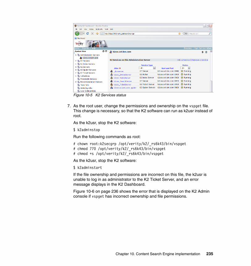
Figure 10-5 K2 Services status
7. As the root user, change the permissions and ownership on the vspget file. This change is necessary, so that the K2 software can run as k2usr instead of root.
As the k2usr, stop the K2 software:
$ k2adminstop
Run the following commands as root:
# chown root:k2secgrp /opt/verity/k2/_rs6k43/bin/vspget# chmod 770 /opt/verity/k2/_rs6k43/bin/vspget# chmod +s /opt/verity/k2/_rs6k43/bin/vspget
As the k2usr, stop the K2 software:
$ k2adminstart
If the file ownership and permissions are incorrect on this file, the k2usr is unable to log in as administrator to the K2 Ticket Server, and an error message displays in the K2 Dashboard.
Figure 10-6 on page 236 shows the error that is displayed on the K2 Admin console if vspget has incorrect ownership and file permissions.
Chapter 10. Content Search Engine implementation 235
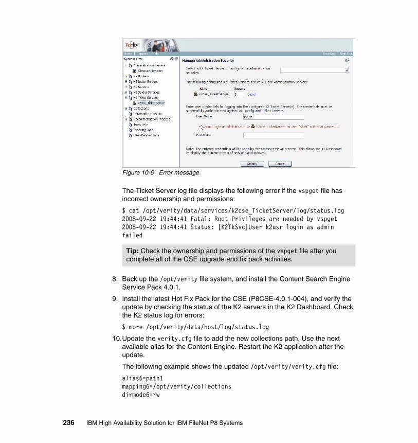
Figure 10-6 Error message
The Ticket Server log file displays the following error if the vspget file has incorrect ownership and permissions:
$ cat /opt/verity/data/services/k2cse_TicketServer/log/status.log2008-09-22 19:44:41 Fatal: Root Privileges are needed by vspget2008-09-22 19:44:41 Status: [K2TkSvc]User k2usr login as admin failed
8. Back up the /opt/verity file system, and install the Content Search Engine Service Pack 4.0.1.
9. Install the latest Hot Fix Pack for the CSE (P8CSE-4.0.1-004), and verify the update by checking the status of the K2 servers in the K2 Dashboard. Check the K2 status log for errors:
$ more /opt/verity/data/host/log/status.log
10.Update the verity.cfg file to add the new collections path. Use the next available alias for the Content Engine. Restart the K2 application after the update.
The following example shows the updated /opt/verity/verity.cfg file:
alias6=path1mapping6=/opt/verity/collectionsdirmode6=rw
Tip: Check the ownership and permissions of the vspget file after you complete all of the CSE upgrade and fix pack activities.
236 IBM High Availability Solution for IBM FileNet P8 Systems
Validating the installationAt this point, the Autonomy K2 software is fully functional and ready for use. Perform the following steps to validate the environment:
1. Create a collection, and index a document.
Example 10-3 indexes the verity.cfg file to a collection called Test. Use the rcvdk utility to perform a null search on the new document, and then, view the document’s contents.
Example 10-3 Indexing the verity.cfg file
$ mkvdk -collection Test /opt/verity/k2/common/verity.cfgmkvdk - Verity, Inc. Version 6.1.4Initializing dataset 00000001.ddd, index 00000001.didTotals (1 documents): 5 para 2 sent 238 word (1680 Kb used)Optimizing database layout(214 ms) Indexed 1 docs into Test/parts/00000001Writing partition index datamkvdk done
$ rcvdk Testrcvdk Verity, Inc. Version 6.1.4 Attaching to collection: TestSuccessfully attached to 1 collection.Type 'help' for a list of commands.RC> sSearch update: finished (100%). Retrieved: 1(1)/1.RC> v1: /opt/verity/k2/common/verity.cfg [Master Admin Server]host=k2cse.svl.ibm.comport=9950[Admin Server]alias=k2cse.svl.ibm.comhost=k2cse.svl.ibm.comport=9950[Launch]launch1=mmclaunch2=k2serverlaunch3=k2broker.....rest of document is displayed.....RC> quit
2. Remove the Test collection.
$ mkvdk -collection Test -purge
Chapter 10. Content Search Engine implementation 237
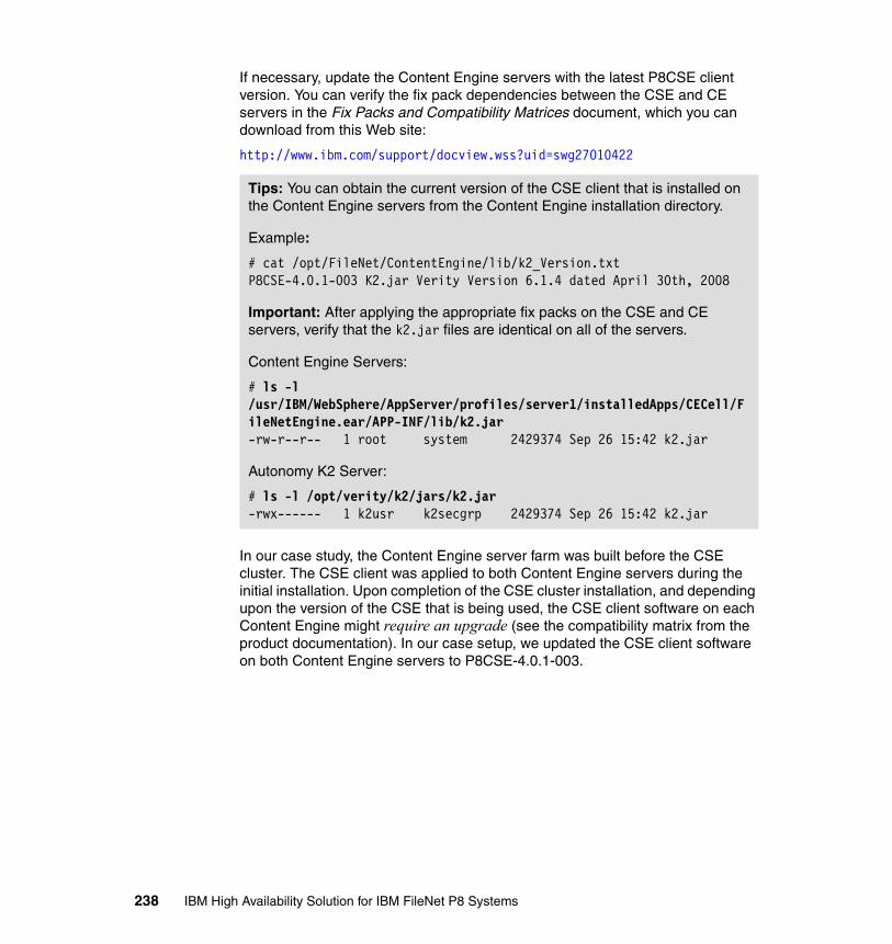
If necessary, update the Content Engine servers with the latest P8CSE client version. You can verify the fix pack dependencies between the CSE and CE servers in the Fix Packs and Compatibility Matrices document, which you can download from this Web site:
http://www.ibm.com/support/docview.wss?uid=swg27010422
In our case study, the Content Engine server farm was built before the CSE cluster. The CSE client was applied to both Content Engine servers during the initial installation. Upon completion of the CSE cluster installation, and depending upon the version of the CSE that is being used, the CSE client software on each Content Engine might require an upgrade (see the compatibility matrix from the product documentation). In our case setup, we updated the CSE client software on both Content Engine servers to P8CSE-4.0.1-003.
Tips: You can obtain the current version of the CSE client that is installed on the Content Engine servers from the Content Engine installation directory.
Example:
# cat /opt/FileNet/ContentEngine/lib/k2_Version.txtP8CSE-4.0.1-003 K2.jar Verity Version 6.1.4 dated April 30th, 2008
Important: After applying the appropriate fix packs on the CSE and CE servers, verify that the k2.jar files are identical on all of the servers.
Content Engine Servers:
# ls -l /usr/IBM/WebSphere/AppServer/profiles/server1/installedApps/CECell/FileNetEngine.ear/APP-INF/lib/k2.jar-rw-r--r-- 1 root system 2429374 Sep 26 15:42 k2.jar
Autonomy K2 Server:
# ls -l /opt/verity/k2/jars/k2.jar-rwx------ 1 k2usr k2secgrp 2429374 Sep 26 15:42 k2.jar
238 IBM High Availability Solution for IBM FileNet P8 Systems

10.4.3 Configure an HACMP resource group for CSE
After the Autonomy K2 software is installed and validated, it can be placed under the control of HACMP. This section describes the steps that are necessary to configure CSE within HACMP.
A single HACMP resource group is required for the CSE cluster. This group contains a shared volume group to host the shared file systems, a service IP label used by the Autonomy K2 software, and a CSE application server resource.
Three custom scripts are created to manage the K2 application within HACMP. These scripts are used by the cluster software to stop, start, and monitor the K2 application. Describing the details of installing and configuring HACMP topologies is outside the scope of this book. You can obtain these steps and other best practices at the following links:
� IBM PowerHA for AIX (HACMP) library:
http://publib.boulder.ibm.com/infocenter/clresctr/vxrx/index.jsp?topic=/com.ibm.cluster.hacmp.doc/hacmpbooks.html
� Implementing High Availability Cluster Multi-Processing (HACMP) Cookbook, SG24-6769
http://www.redbooks.ibm.com/abstracts/sg246769.html
Use the following steps to configure CSE within HACMP:
1. Create the start, stop, and monitor shell scripts that HACMP calls to manage the Content Search Engine. There are many possible ways to write the scripts to accomplish the function.
Note: When upgrading the CSE client software on each Content Engine, the patch introduces a new Engine-ws.ear file. Therefore, the original file must be backed up, then undeployed. The new Engine-ws.ear file contained in the P8CSE-4.0.1-003 Fix Pack is then deployed (see the Fix Pack readme file for further details).
For additional information about Content Engine and CSE dependencies and compatibility, refer to the following documents at this Web site
http://www.ibm.com/support/docview.wss?rs=3278&uid=swg27010422:
� IBM FileNet P8 Hardware and Software Requirements Guide
� Fix Packs and Compatibility Matrices
Chapter 10. Content Search Engine implementation 239

The following scripts were implemented successfully in our lab environment. We provide them here as examples for your reference:
– Example 10-4 shows the start script for CSE.
The script first checks to ensure that the /opt/FileNet/FileStore NFS is mounted before running k2adminstart. If the file system is not mounted, the script exits with a status=1, and K2 is not started.
Example 10-4 Start script
root@fnl41:/root>cat /opt/FileNet/ha_scripts/cse_start.sh
#!/bin/ksh
CEFS="/opt/FileNet/FileStore"
echo "Checking if the CE filestore is mounted ..."mount | grep -w "$CEFS"if [ $? -ne 0 ]; then echo "ERROR: FileStore not mounted!!!!\n Exiting without starting CSE!"; exit 1 ; fi
echo "Starting Content Search Engine ....."
############################################################ Run the K2 start script ############################################################su - k2usr "-c /opt/verity/k2/_rs6k43/bin/k2adminstart"
exit 0
– Example 10-5 shows the stop script for CSE.
The script first stops the k2admin process, and then, the remaining k2usr child processes. After these processes are stopped, Catalina Tomcat is stopped.
Example 10-5 Stop script
root@fnl41:/root>cat /opt/FileNet/ha_scripts/cse_stop.sh
#!/bin/kshDATA_DIR="/opt/verity/data"# The process ID is kept in the k2admin.pid file under $DATA_DIR/host/logPLATFORM="_rs6k43"VERITY_DIR="/opt/verity"VERITY_LOG="$DATA_DIR/host/log"VERITY_BIN="$VERITY_DIR/k2/$PLATFORM/bin"VERITY_COMMON="$VERITY_DIR/k2/common"VERITY_CFG="/opt/verity/k2/common/verity.cfg"
240 IBM High Availability Solution for IBM FileNet P8 Systems

PATH=$VERITY_BIN:$PATH; export PATHLIBPATH=$VERITY_BIN:$LIBPATH;export LIBPATHTOMCAT_HOME="/opt/verity/appserver"; export TOMCAT_HOMECATALINA_HOME="/opt/verity/appserver"; export CATALINA_HOMEif [ -z "$JAVA_HOME" ]; thenJAVA_HOME="/usr/java5_64"; export JAVA_HOMEfi
echo "Stopping Content Search Engine ....."
pidk2adm=`cat $VERITY_LOG/k2admin.pid` if [ `ps -e | grep "k2admin" | grep $pidk2adm | grep -v grep | grep -v k2adminstop | wc -l ` -gt 0 ]; thenif [[ $pidk2adm != "" ]]; then kill -HUP "$pidk2adm" ; fifi
sleep 10
pidsk2=`ps -fu k2usr | grep "$pidk2adm" | grep -v "k2admin" | grep -v grep | awk '{print $2}'`for i in $pidsk2dokill -9 $idoneif [ `ps -e | grep "k2admin" | grep $pidk2adm | grep -v grep | grep -v k2adminstop | wc -l ` -gt 0 ]; thenif [[ $pidk2adm != "" ]]; then kill -9 "$pidk2adm" ; fifi
sleep 10if [ -f $VERITY_DIR/appserver/bin/catalina.sh ]; then $VERITY_DIR/appserver/bin/catalina.sh stop -force >/dev/nullfi
if [ `ps -p "$pidk2adm $pidsk2" 2>/dev/null |tail +2 |wc -l` -ne 0 ] then echo "K2 processes still running!!!!\nCheck the application status!!!"fi
exit 0
– Monitor script for CSE.
The monitor script checks to see if the following seven critical K2 server processes are running:
/opt/verity/k2/_rs6k43/bin/k2admin /opt/verity/k2/_rs6k43/bin/k2index -ualias k2cse_IndexServer /opt/verity/k2/_rs6k43/bin/k2server -ualias k2cse_SearchServer
Chapter 10. Content Search Engine implementation 241
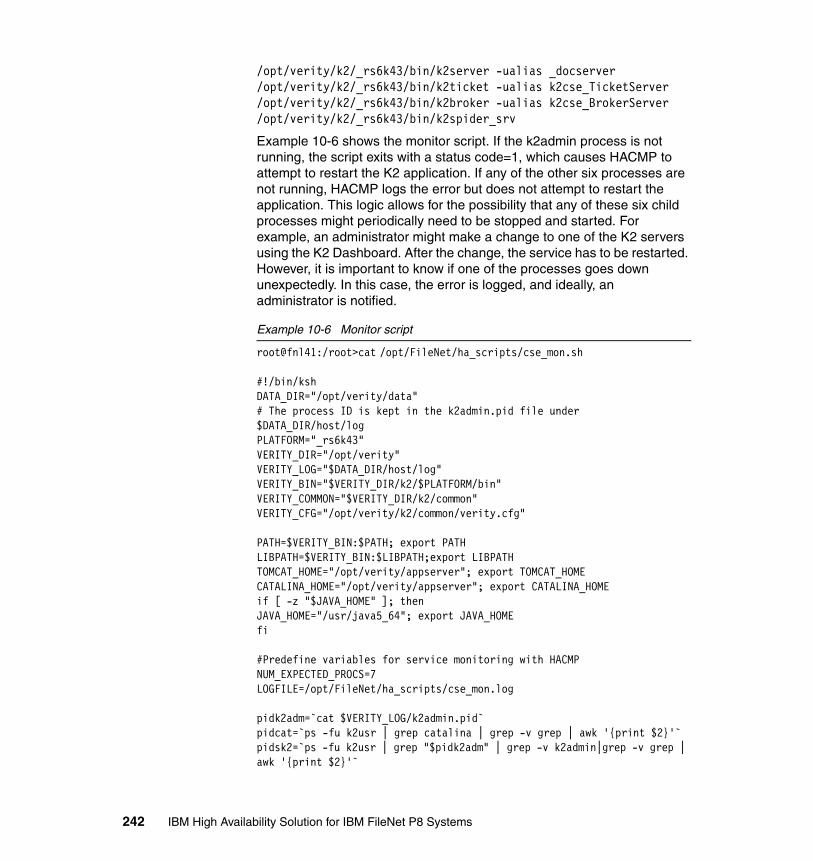
/opt/verity/k2/_rs6k43/bin/k2server -ualias _docserver /opt/verity/k2/_rs6k43/bin/k2ticket -ualias k2cse_TicketServer /opt/verity/k2/_rs6k43/bin/k2broker -ualias k2cse_BrokerServer /opt/verity/k2/_rs6k43/bin/k2spider_srv
Example 10-6 shows the monitor script. If the k2admin process is not running, the script exits with a status code=1, which causes HACMP to attempt to restart the K2 application. If any of the other six processes are not running, HACMP logs the error but does not attempt to restart the application. This logic allows for the possibility that any of these six child processes might periodically need to be stopped and started. For example, an administrator might make a change to one of the K2 servers using the K2 Dashboard. After the change, the service has to be restarted. However, it is important to know if one of the processes goes down unexpectedly. In this case, the error is logged, and ideally, an administrator is notified.
Example 10-6 Monitor script
root@fnl41:/root>cat /opt/FileNet/ha_scripts/cse_mon.sh
#!/bin/kshDATA_DIR="/opt/verity/data"# The process ID is kept in the k2admin.pid file under $DATA_DIR/host/logPLATFORM="_rs6k43"VERITY_DIR="/opt/verity"VERITY_LOG="$DATA_DIR/host/log"VERITY_BIN="$VERITY_DIR/k2/$PLATFORM/bin"VERITY_COMMON="$VERITY_DIR/k2/common"VERITY_CFG="/opt/verity/k2/common/verity.cfg"
PATH=$VERITY_BIN:$PATH; export PATHLIBPATH=$VERITY_BIN:$LIBPATH;export LIBPATHTOMCAT_HOME="/opt/verity/appserver"; export TOMCAT_HOMECATALINA_HOME="/opt/verity/appserver"; export CATALINA_HOMEif [ -z "$JAVA_HOME" ]; thenJAVA_HOME="/usr/java5_64"; export JAVA_HOMEfi
#Predefine variables for service monitoring with HACMPNUM_EXPECTED_PROCS=7LOGFILE=/opt/FileNet/ha_scripts/cse_mon.log
pidk2adm=`cat $VERITY_LOG/k2admin.pid` pidcat=`ps -fu k2usr | grep catalina | grep -v grep | awk '{print $2}'`pidsk2=`ps -fu k2usr | grep "$pidk2adm" | grep -v k2admin|grep -v grep | awk '{print $2}'`
242 IBM High Availability Solution for IBM FileNet P8 Systems

if [ `ps -e | grep "k2admin" | grep $pidk2adm | grep -v grep | grep -v k2adminstop | wc -l ` -eq 0 ]; thenlogger -i -p notice -t $0 "cse_mon: No k2admin process found!"exit 1fi
if [ `ps -p "$pidcat $pidsk2" 2>/dev/null |tail +2 |wc -l` -ne ${NUM_EXPECTED_PROCS} ] then
echo "Number of expected procs is $NUM_EXPECTED_PROCS" > $LOGFILE echo "Number of k2 processes running is not the same as the number of expected processes !!!!" >> $LOGFILE echo "Status of the K2 server process currently running:" >> $LOGFILE echo "=================================================================================================" >> $LOGFILE ps -p "$pidcat $pidsk2" >> $LOGFILE 2>/dev/null echo "=================================================================================================" >> $LOGFILE logger -i -p notice -t $0 -f $LOGFILE
fi
exit 0
Before incorporating the start, monitor, and stop scripts into HACMP, ensure that they can be successfully run (as root) from the command line.
Run cse_mon.sh while K2 is up and running. An exit status=0 indicates that the script detected all of the processes running:
root@fnl41:/opt/FileNet/ha_scripts>./cse_mon.sh root@fnl41:/opt/FileNet/ha_scripts>echo $? 0
Stop the K2 processes. The cse_mon.sh script returns an Exit status=1:
root@fnl41:/opt/FileNet/ha_scripts>./cse_stop.sh Stopping Content Search Engine .....root@fnl41:/opt/FileNet/ha_scripts>ps -ef | grep k2 root 839704 1077348 2 14:34:20 pts/1 0:00 grep k2root@fnl41:/opt/FileNet/ha_scripts>./cse_mon.sh root@fnl41:/opt/FileNet/ha_scripts>echo $?1
Example 10-7 on page 244 shows the K2 processes starting after issuing the start script. We can verify if all the processes have successfully started using the ps -ef | grep k2 command.
Chapter 10. Content Search Engine implementation 243
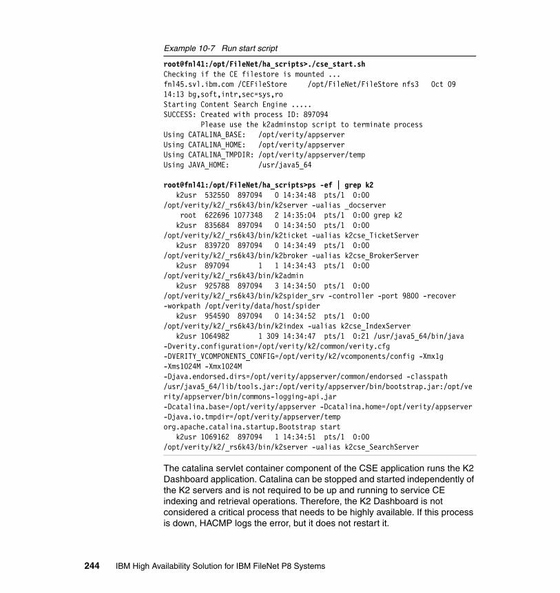
Example 10-7 Run start script
root@fnl41:/opt/FileNet/ha_scripts>./cse_start.sh Checking if the CE filestore is mounted ...fnl45.svl.ibm.com /CEFileStore /opt/FileNet/FileStore nfs3 Oct 09 14:13 bg,soft,intr,sec=sys,roStarting Content Search Engine .....SUCCESS: Created with process ID: 897094 Please use the k2adminstop script to terminate processUsing CATALINA_BASE: /opt/verity/appserverUsing CATALINA_HOME: /opt/verity/appserverUsing CATALINA_TMPDIR: /opt/verity/appserver/tempUsing JAVA_HOME: /usr/java5_64
root@fnl41:/opt/FileNet/ha_scripts>ps -ef | grep k2 k2usr 532550 897094 0 14:34:48 pts/1 0:00 /opt/verity/k2/_rs6k43/bin/k2server -ualias _docserver root 622696 1077348 2 14:35:04 pts/1 0:00 grep k2 k2usr 835684 897094 0 14:34:50 pts/1 0:00 /opt/verity/k2/_rs6k43/bin/k2ticket -ualias k2cse_TicketServer k2usr 839720 897094 0 14:34:49 pts/1 0:00 /opt/verity/k2/_rs6k43/bin/k2broker -ualias k2cse_BrokerServer k2usr 897094 1 1 14:34:43 pts/1 0:00 /opt/verity/k2/_rs6k43/bin/k2admin k2usr 925788 897094 3 14:34:50 pts/1 0:00 /opt/verity/k2/_rs6k43/bin/k2spider_srv -controller -port 9800 -recover -workpath /opt/verity/data/host/spider k2usr 954590 897094 0 14:34:52 pts/1 0:00 /opt/verity/k2/_rs6k43/bin/k2index -ualias k2cse_IndexServer k2usr 1064982 1 309 14:34:47 pts/1 0:21 /usr/java5_64/bin/java -Dverity.configuration=/opt/verity/k2/common/verity.cfg -DVERITY_VCOMPONENTS_CONFIG=/opt/verity/k2/vcomponents/config -Xmx1g -Xms1024M -Xmx1024M -Djava.endorsed.dirs=/opt/verity/appserver/common/endorsed -classpath /usr/java5_64/lib/tools.jar:/opt/verity/appserver/bin/bootstrap.jar:/opt/verity/appserver/bin/commons-logging-api.jar -Dcatalina.base=/opt/verity/appserver -Dcatalina.home=/opt/verity/appserver -Djava.io.tmpdir=/opt/verity/appserver/temp org.apache.catalina.startup.Bootstrap start k2usr 1069162 897094 1 14:34:51 pts/1 0:00 /opt/verity/k2/_rs6k43/bin/k2server -ualias k2cse_SearchServer
The catalina servlet container component of the CSE application runs the K2 Dashboard application. Catalina can be stopped and started independently of the K2 servers and is not required to be up and running to service CE indexing and retrieval operations. Therefore, the K2 Dashboard is not considered a critical process that needs to be highly available. If this process is down, HACMP logs the error, but it does not restart it.
244 IBM High Availability Solution for IBM FileNet P8 Systems

Example 10-8 shows the catalina process running on the active node of the cluster.
Example 10-8 Catalina process
$ ps -ef | grep catalinak2usr 839682 1 /usr/java5_64/bin/java -Dverity.configuration=/opt/verity/k2/common/verity.cfg - DVERITY_VCOMPONENTS_CONFIG=/opt/verity/k2/vcomponents/config -Xmx1g -Xms1024M -Xmx1024M - Djava.endorsed.dirs=/opt/verity/appserver/common/endorsed -classpath /usr/java5_64/lib/tools.jar:/opt/verity/appserver/bin/bootstrap.jar:/opt/verity/appserver/bin/commons-logging-api.jar - Dcatalina.base=/opt/verity/appserver -Dcatalina.home=/opt/verity/appserver -Djava.io.tmpdir=/opt/verity/appserver/temp org.apache.catalina.startup.Bootstrap start
You can stop and start the K2 Dashboard (as k2usr) using the following commands:
$ /opt/verity/appserver/bin/catalina.sh stop$ /opt/verity/appserver/bin/catalina.sh start
Figure 10-7 on page 246 illustrates a successful logon to the K2 Application Server (K2 Dashboard) after running the catalina.sh start command.
Chapter 10. Content Search Engine implementation 245
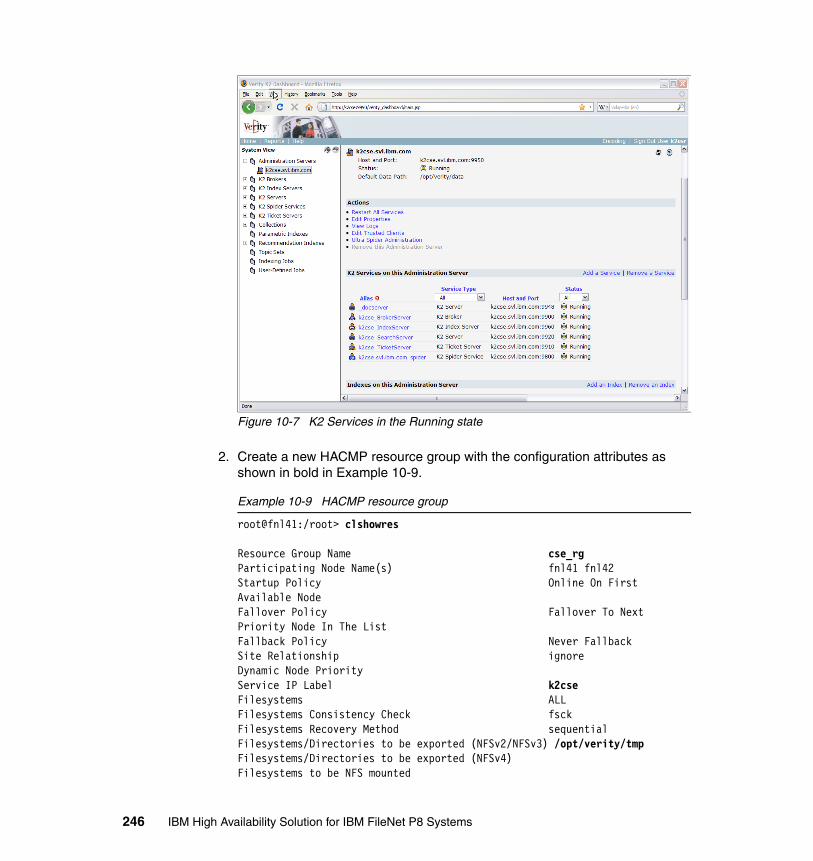
Figure 10-7 K2 Services in the Running state
2. Create a new HACMP resource group with the configuration attributes as shown in bold in Example 10-9.
Example 10-9 HACMP resource group
root@fnl41:/root> clshowres
Resource Group Name cse_rg Participating Node Name(s) fnl41 fnl42 Startup Policy Online On First Available Node Fallover Policy Fallover To Next Priority Node In The List Fallback Policy Never Fallback Site Relationship ignore Dynamic Node Priority Service IP Label k2cse Filesystems ALL Filesystems Consistency Check fsckFilesystems Recovery Method sequentialFilesystems/Directories to be exported (NFSv2/NFSv3) /opt/verity/tmp Filesystems/Directories to be exported (NFSv4) Filesystems to be NFS mounted
246 IBM High Availability Solution for IBM FileNet P8 Systems
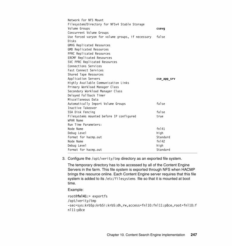
Network For NFS Mount Filesystem/Directory for NFSv4 Stable Storage Volume Groups csevg Concurrent Volume Groups Use forced varyon for volume groups, if necessary false Disks GMVG Replicated Resources GMD Replicated Resources PPRC Replicated Resources ERCMF Replicated Resources SVC PPRC Replicated Resources Connections Services Fast Connect Services Shared Tape Resources Application Servers cse_app_srv Highly Available Communication Links Primary Workload Manager Class Secondary Workload Manager Class Delayed Fallback Timer Miscellaneous Data Automatically Import Volume Groups false Inactive Takeover SSA Disk Fencing false Filesystems mounted before IP configured trueWPAR NameRun Time Parameters:Node Name fnl41Debug Level high Format for hacmp.out Standard Node Name fnl42Debug Level high Format for hacmp.out Standard
3. Configure the /opt/verity/tmp directory as an exported file system.
The temporary directory has to be accessed by all of the Content Engine Servers in the farm. This file system is exported through NFS when HACMP brings the resource online. Each Content Engine server requires that this file system is added to its /etc/filesystems file so that it is mounted at boot time.
Example:
root@fnl41:> exportfs/opt/verity/tmp -sec=sys:krb5p:krb5i:krb5:dh,rw,access=fnl10:fnl11:p8ce,root=fnl10:fnl11:p8ce
Chapter 10. Content Search Engine implementation 247
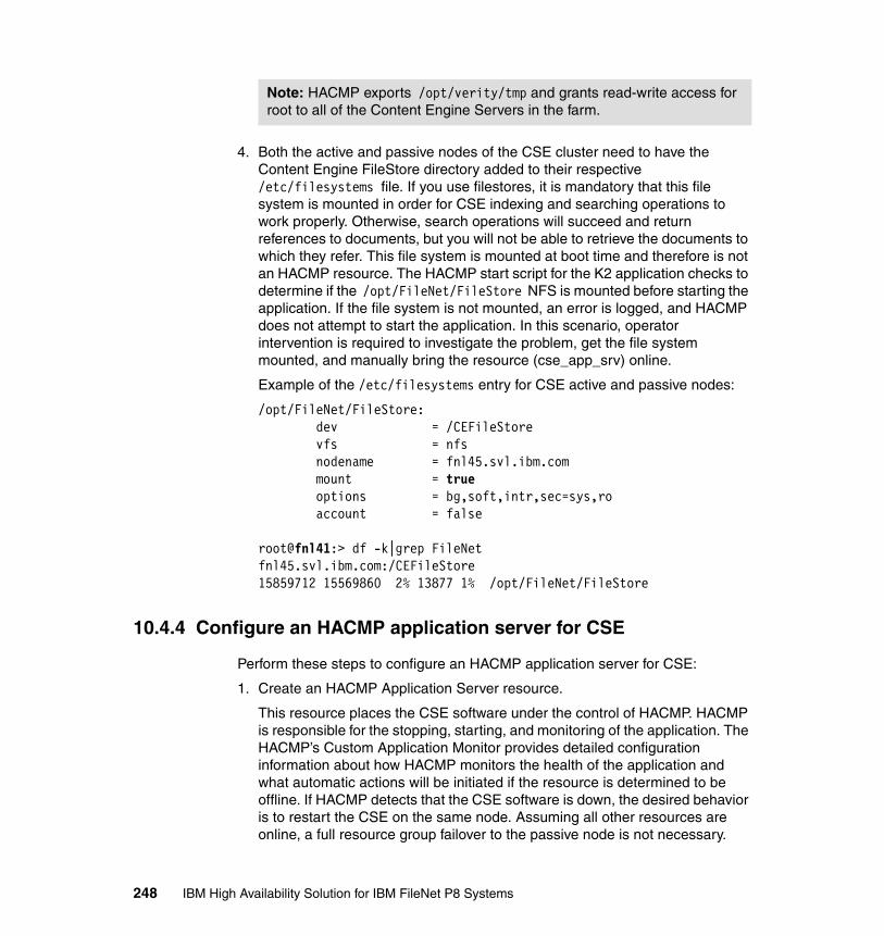
4. Both the active and passive nodes of the CSE cluster need to have the Content Engine FileStore directory added to their respective /etc/filesystems file. If you use filestores, it is mandatory that this file system is mounted in order for CSE indexing and searching operations to work properly. Otherwise, search operations will succeed and return references to documents, but you will not be able to retrieve the documents to which they refer. This file system is mounted at boot time and therefore is not an HACMP resource. The HACMP start script for the K2 application checks to determine if the /opt/FileNet/FileStore NFS is mounted before starting the application. If the file system is not mounted, an error is logged, and HACMP does not attempt to start the application. In this scenario, operator intervention is required to investigate the problem, get the file system mounted, and manually bring the resource (cse_app_srv) online.
Example of the /etc/filesystems entry for CSE active and passive nodes:
/opt/FileNet/FileStore: dev = /CEFileStore vfs = nfs nodename = fnl45.svl.ibm.com mount = true options = bg,soft,intr,sec=sys,ro account = false
root@fnl41:> df -k|grep FileNetfnl45.svl.ibm.com:/CEFileStore 15859712 15569860 2% 13877 1% /opt/FileNet/FileStore
10.4.4 Configure an HACMP application server for CSE
Perform these steps to configure an HACMP application server for CSE:
1. Create an HACMP Application Server resource.
This resource places the CSE software under the control of HACMP. HACMP is responsible for the stopping, starting, and monitoring of the application. The HACMP’s Custom Application Monitor provides detailed configuration information about how HACMP monitors the health of the application and what automatic actions will be initiated if the resource is determined to be offline. If HACMP detects that the CSE software is down, the desired behavior is to restart the CSE on the same node. Assuming all other resources are online, a full resource group failover to the passive node is not necessary.
Note: HACMP exports /opt/verity/tmp and grants read-write access for root to all of the Content Engine Servers in the farm.
248 IBM High Availability Solution for IBM FileNet P8 Systems
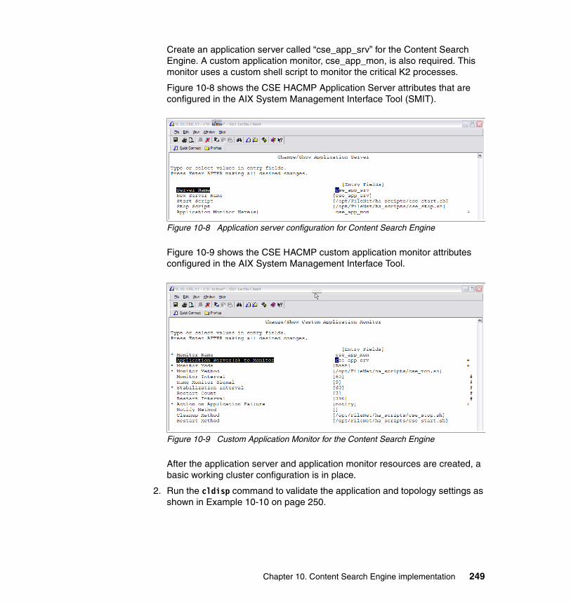
Create an application server called “cse_app_srv” for the Content Search Engine. A custom application monitor, cse_app_mon, is also required. This monitor uses a custom shell script to monitor the critical K2 processes.
Figure 10-8 shows the CSE HACMP Application Server attributes that are configured in the AIX System Management Interface Tool (SMIT).
Figure 10-8 Application server configuration for Content Search Engine
Figure 10-9 shows the CSE HACMP custom application monitor attributes configured in the AIX System Management Interface Tool.
Figure 10-9 Custom Application Monitor for the Content Search Engine
After the application server and application monitor resources are created, a basic working cluster configuration is in place.
2. Run the cldisp command to validate the application and topology settings as shown in Example 10-10 on page 250.
Chapter 10. Content Search Engine implementation 249
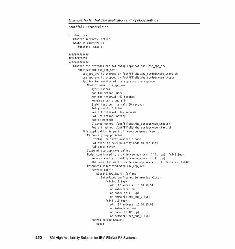
Example 10-10 Validate application and topology settings
root@fnl41:/root>cldisp
Cluster: cse Cluster services: active State of cluster: up Substate: stable
#############APPLICATIONS############# Cluster cse provides the following applications: cse_app_srv Application: cse_app_srv cse_app_srv is started by /opt/FileNet/ha_scripts/cse_start.sh cse_app_srv is stopped by /opt/FileNet/ha_scripts/cse_stop.sh Application monitor of cse_app_srv: cse_app_mon Monitor name: cse_app_mon Type: custom Monitor method: user Monitor interval: 60 seconds Hung monitor signal: 9 Stabilization interval: 60 seconds Retry count: 3 tries Restart interval: 396 seconds Failure action: notify Notify method: Cleanup method: /opt/FileNet/ha_scripts/cse_stop.sh Restart method: /opt/FileNet/ha_scripts/cse_start.sh This application is part of resource group 'cse_rg'. Resource group policies: Startup: on first available node Fallover: to next priority node in the list Fallback: never State of cse_app_srv: online Nodes configured to provide cse_app_srv: fnl41 {up} fnl42 {up} Node currently providing cse_app_srv: fnl41 {up} The node that will provide cse_app_srv if fnl41 fails is: fnl42 Resources associated with cse_app_srv: Service Labels k2cse(9.30.188.77) {online} Interfaces configured to provide k2cse: fnl41-bt1 {up} with IP address: 10.10.10.51 on interface: en2 on node: fnl41 {up} on network: net_pub_1 {up} fnl42-bt1 {up} with IP address: 10.10.10.52 on interface: en2 on node: fnl42 {up} on network: net_pub_1 {up} Shared Volume Groups: csevg
250 IBM High Availability Solution for IBM FileNet P8 Systems

#############TOPOLOGY############# cse consists of the following nodes: fnl41 fnl42 fnl41 Network interfaces: fnl41_vpath0_01 {up} device: /dev/vpath0 on network: net_diskhb_01 {up} fnl41-hs03 {up} with IP address: 10.0.3.51 on interface: en3 on network: net_priv_1 {up} fnl41-bt1 {up} with IP address: 10.10.10.51 on interface: en2 on network: net_pub_1 {up} fnl42 Network interfaces: fnl42_vpath0_01 {up} device: /dev/vpath0 on network: net_diskhb_01 {up} fnl42-hs03 {up} with IP address: 10.0.3.52 on interface: en3 on network: net_priv_1 {up} fnl42-bt1 {up} with IP address: 10.10.10.52 on interface: en2 on network: net_pub_1 {up}root@fnl41:/root>
3. Configure HACMP File Collection to keep the CSE user profiles and application scripts synchronized across the active/passive nodes:
– /home/k2usr/.profile– /home/k2sec/.profile– /opt/FileNet/ha_scripts/cse_start.sh– /opt/FileNet/ha_scripts/cse_stop.sh– /opt/FileNet/ha_scripts/cse_mon.sh
Figure 10-10 on page 252 shows the file collection settings for the CSE custom scripts.
Chapter 10. Content Search Engine implementation 251
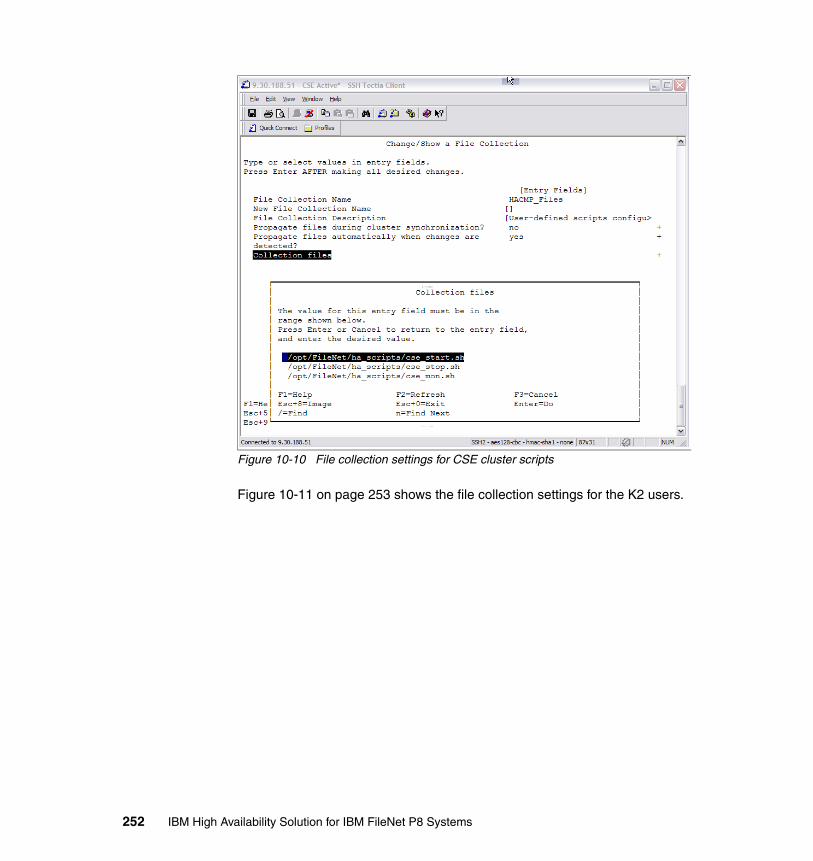
Figure 10-10 File collection settings for CSE cluster scripts
Figure 10-11 on page 253 shows the file collection settings for the K2 users.
252 IBM High Availability Solution for IBM FileNet P8 Systems
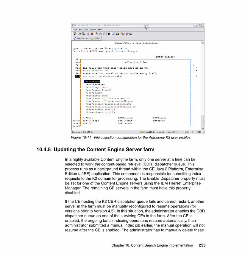
Figure 10-11 File collection configuration for the Autonomy K2 user profiles
10.4.5 Updating the Content Engine Server farm
In a highly available Content Engine farm, only one server at a time can be selected to work the content-based retrieval (CBR) dispatcher queue. This process runs as a background thread within the CE Java 2 Platform, Enterprise Edition (J2EE) application. This component is responsible for submitting index requests to the K2 domain for processing. The Enable Dispatcher property must be set for one of the Content Engine servers using the IBM FileNet Enterprise Manager. The remaining CE servers in the farm must have this property disabled.
If the CE hosting the K2 CBR dispatcher queue fails and cannot restart, another server in the farm must be manually reconfigured to resume operations (for versions prior to Version 4.5). In this situation, the administrator enables the CBR dispatcher queue on one of the surviving CEs in the farm. After the CE is enabled, the ongoing batch indexing operations resume automatically. If an administrator submitted a manual index job earlier, the manual operation will not resume after the CE is enabled. The administrator has to manually delete these
Chapter 10. Content Search Engine implementation 253

jobs from the Index jobs list control and resubmit them after the dispatcher queue is up and running again.
For pre-4.0.1-004 versions of the Content Engine, the CBR dispatcher represents a single point of failure (SPOF) requiring manual intervention after the hosting CE fails. Starting from Version 4.0.1, index jobs automatically recover. Starting from Version 4.5, the dispatcher automatically starts on another working Content Engine server. The Content Engine picks one of the CBR-enabled servers that is up and running to perform the dispatcher function.
See the “Configure CBR” section of ECM Help and the P8 Platform Installation Guide for detailed procedures about how to configure and enable CBR. All of the P8 product documentation can be found at the following Web site:
http://www.ibm.com/support/docview.wss?rs=3278&uid=swg27010422
Before configuring content-based retrieval within IBM FileNet Enterprise Manager, validate that each Content Engine server has a supported version of the P8CSE client installed. Also, ensure that all CE servers in the farm have the K2 temp directory mounted. Add this NFS mount to the /etc/filesystems file on each Content Engine server.
Perform these steps to update the CE servers:
1. Add the remote K2 temp directory on each Content Engine server to /etc/filesystems.
The following example shows our filesystems file content:
root@fnl10[/root] tail /etc/filesystems/opt/verity/tmp: dev = "/opt/verity/tmp" vfs = nfs nodename = k2cse mount = true type = verity options = bg,soft,intr,sec=sys account = false
root@fnl10[/root] df -k|grep verityk2cse:/opt/verity/tmp 2097152 2096468 1% 14 1% /opt/verity/tmp
2. Configure the K2 domain configuration information in IBM FileNet Enterprise Manager.
Use the virtual name of the CSE cluster when specifying the Hostname for the K2 Master Admin Server Information.
254 IBM High Availability Solution for IBM FileNet P8 Systems
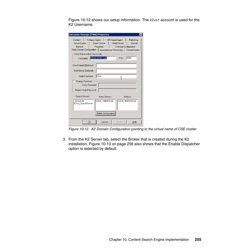
Figure 10-12 shows our setup information. The k2usr account is used for the K2 Username.
Figure 10-12 K2 Domain Configuration pointing to the virtual name of CSE cluster
3. From the K2 Server tab, select the Broker that is created during the K2 installation. Figure 10-13 on page 256 also shows that the Enable Dispatcher option is selected by default.
Chapter 10. Content Search Engine implementation 255
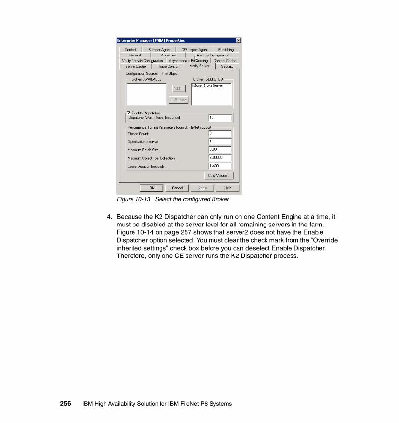
Figure 10-13 Select the configured Broker
4. Because the K2 Dispatcher can only run on one Content Engine at a time, it must be disabled at the server level for all remaining servers in the farm. Figure 10-14 on page 257 shows that server2 does not have the Enable Dispatcher option selected. You must clear the check mark from the “Override inherited settings” check box before you can deselect Enable Dispatcher. Therefore, only one CE server runs the K2 Dispatcher process.
256 IBM High Availability Solution for IBM FileNet P8 Systems
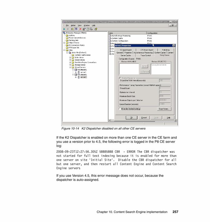
Figure 10-14 K2 Dispatcher disabled on all other CE servers
If the K2 Dispatcher is enabled on more than one CE server in the CE farm and you use a version prior to 4.5, the following error is logged in the P8 CE server log:
2008-09-23T12:27:56.305Z 5BB85BB8 CBR - ERROR The CBR dispatcher was not started for full text indexing because it is enabled for more than one server on site 'Initial Site'. Disable the CBR dispatcher for all but one server, and then restart all Content Engine and Content Search Engine servers
If you use Version 4.5, this error message does not occur, because the dispatcher is auto-assigned.
Chapter 10. Content Search Engine implementation 257
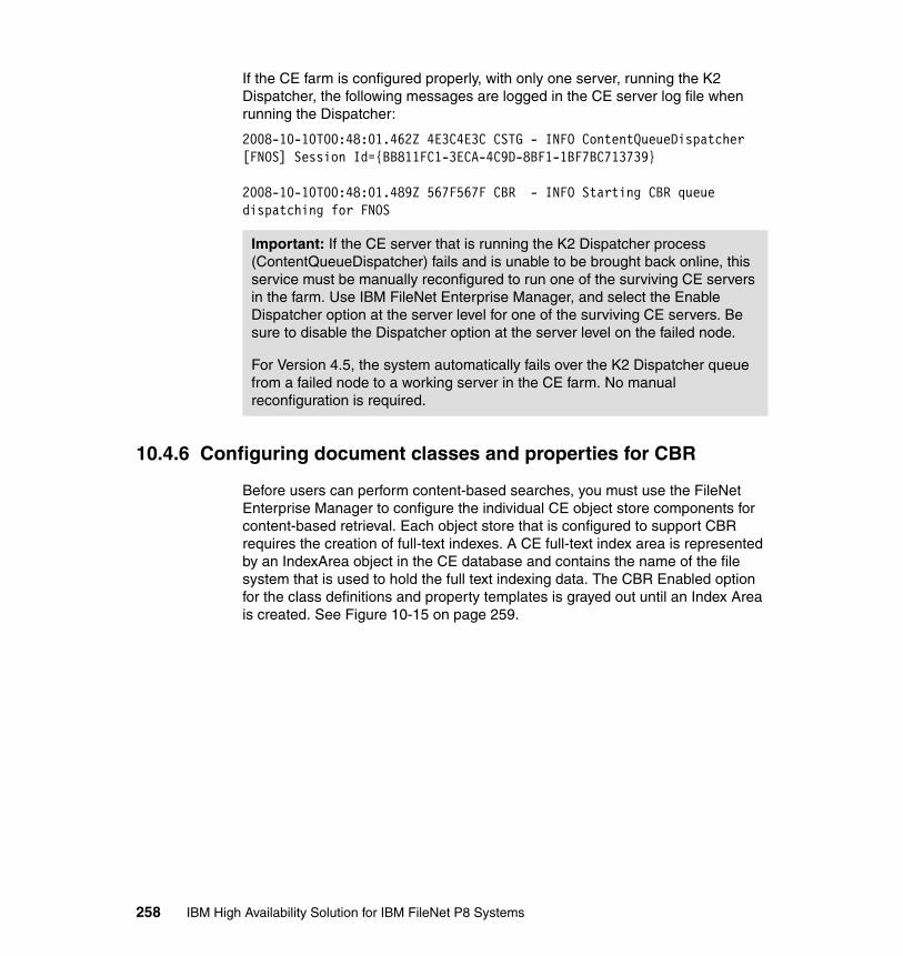
If the CE farm is configured properly, with only one server, running the K2 Dispatcher, the following messages are logged in the CE server log file when running the Dispatcher:
2008-10-10T00:48:01.462Z 4E3C4E3C CSTG - INFO ContentQueueDispatcher [FNOS] Session Id={BB811FC1-3ECA-4C9D-8BF1-1BF7BC713739}
2008-10-10T00:48:01.489Z 567F567F CBR - INFO Starting CBR queue dispatching for FNOS
10.4.6 Configuring document classes and properties for CBR
Before users can perform content-based searches, you must use the FileNet Enterprise Manager to configure the individual CE object store components for content-based retrieval. Each object store that is configured to support CBR requires the creation of full-text indexes. A CE full-text index area is represented by an IndexArea object in the CE database and contains the name of the file system that is used to hold the full text indexing data. The CBR Enabled option for the class definitions and property templates is grayed out until an Index Area is created. See Figure 10-15 on page 259.
Important: If the CE server that is running the K2 Dispatcher process (ContentQueueDispatcher) fails and is unable to be brought back online, this service must be manually reconfigured to run one of the surviving CE servers in the farm. Use IBM FileNet Enterprise Manager, and select the Enable Dispatcher option at the server level for one of the surviving CE servers. Be sure to disable the Dispatcher option at the server level on the failed node.
For Version 4.5, the system automatically fails over the K2 Dispatcher queue from a failed node to a working server in the CE farm. No manual reconfiguration is required.
258 IBM High Availability Solution for IBM FileNet P8 Systems

Figure 10-15 Unable to select the CBR Enabled property
For detailed information about creating index areas and configuring CBR, see the IBM P8 Platform Installation and Upgrade Guide and ECM Help.
For our case study, we use the following procedures to create an index area and configure CBR for a Document Class:
1. Set the object store Default Locale to en-us (English) as shown in Figure 10-16 on page 260.
Chapter 10. Content Search Engine implementation 259
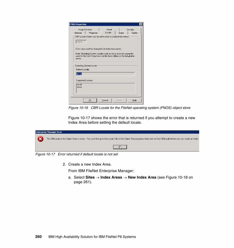
Figure 10-16 CBR Locale for the FileNet operating system (FNOS) object store
Figure 10-17 shows the error that is returned if you attempt to create a new Index Area before setting the default locale.
Figure 10-17 Error returned if default locale is not set
2. Create a new Index Area.
From IBM FileNet Enterprise Manager:
a. Select Sites → Index Areas → New Index Area (see Figure 10-18 on page 261).
260 IBM High Availability Solution for IBM FileNet P8 Systems
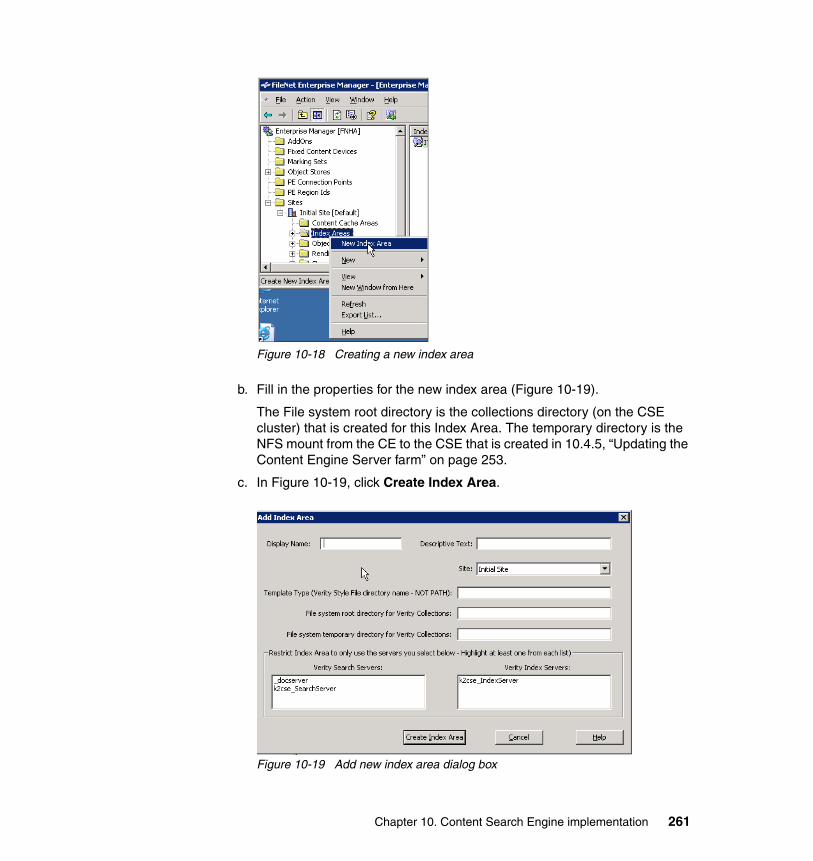
Figure 10-18 Creating a new index area
b. Fill in the properties for the new index area (Figure 10-19).
The File system root directory is the collections directory (on the CSE cluster) that is created for this Index Area. The temporary directory is the NFS mount from the CE to the CSE that is created in 10.4.5, “Updating the Content Engine Server farm” on page 253.
c. In Figure 10-19, click Create Index Area.
Figure 10-19 Add new index area dialog box
Chapter 10. Content Search Engine implementation 261
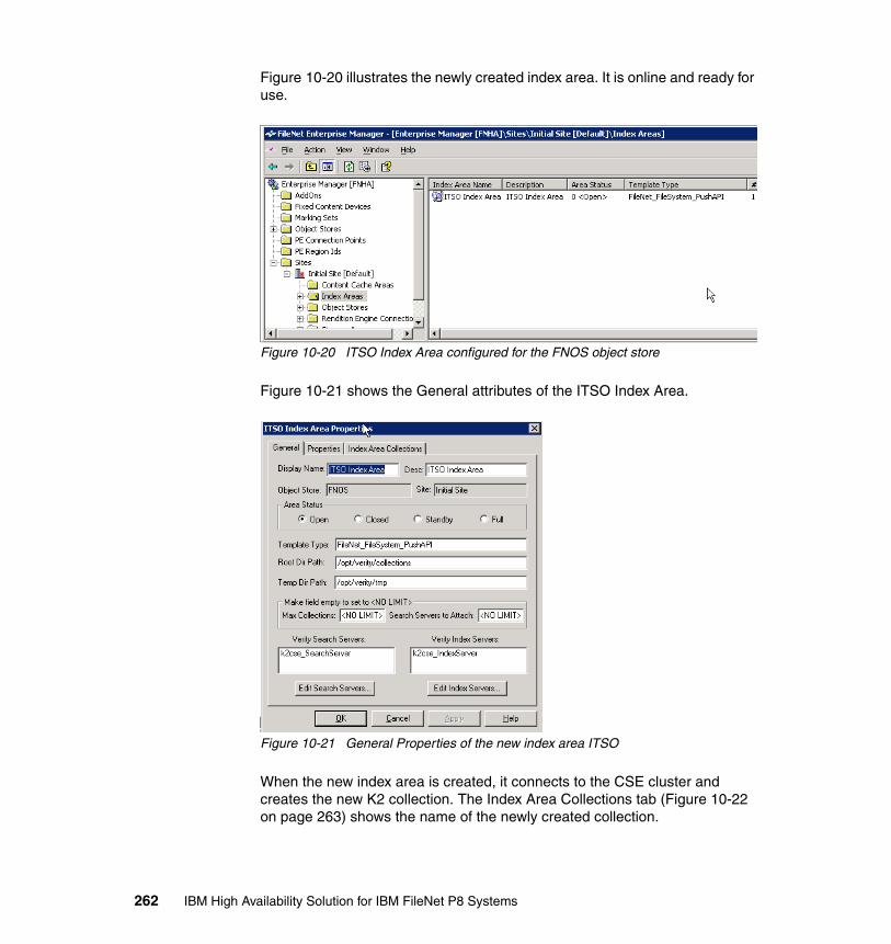
Figure 10-20 illustrates the newly created index area. It is online and ready for use.
Figure 10-20 ITSO Index Area configured for the FNOS object store
Figure 10-21 shows the General attributes of the ITSO Index Area.
Figure 10-21 General Properties of the new index area ITSO
When the new index area is created, it connects to the CSE cluster and creates the new K2 collection. The Index Area Collections tab (Figure 10-22 on page 263) shows the name of the newly created collection.
262 IBM High Availability Solution for IBM FileNet P8 Systems
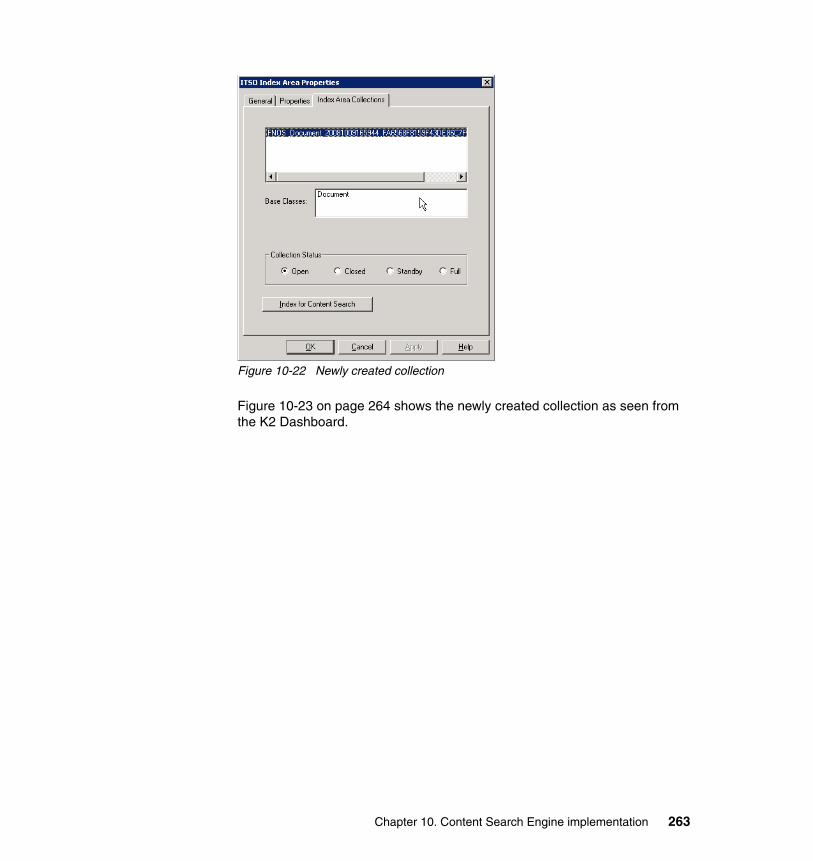
Figure 10-22 Newly created collection
Figure 10-23 on page 264 shows the newly created collection as seen from the K2 Dashboard.
Chapter 10. Content Search Engine implementation 263
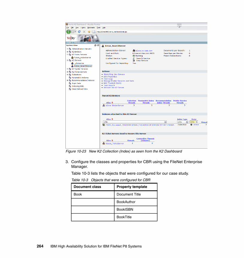
Figure 10-23 New K2 Collection (Index) as seen from the K2 Dashboard
3. Configure the classes and properties for CBR using the FileNet Enterprise Manager.
Table 10-3 lists the objects that were configured for our case study.
Table 10-3 Objects that were configured for CBR
Document class Property template
Book Document Title
BookAuthor
BookISBN
BookTitle
264 IBM High Availability Solution for IBM FileNet P8 Systems
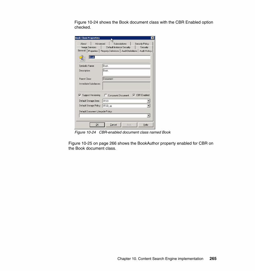
Figure 10-24 shows the Book document class with the CBR Enabled option checked.
Figure 10-24 CBR-enabled document class named Book
Figure 10-25 on page 266 shows the BookAuthor property enabled for CBR on the Book document class.
Chapter 10. Content Search Engine implementation 265
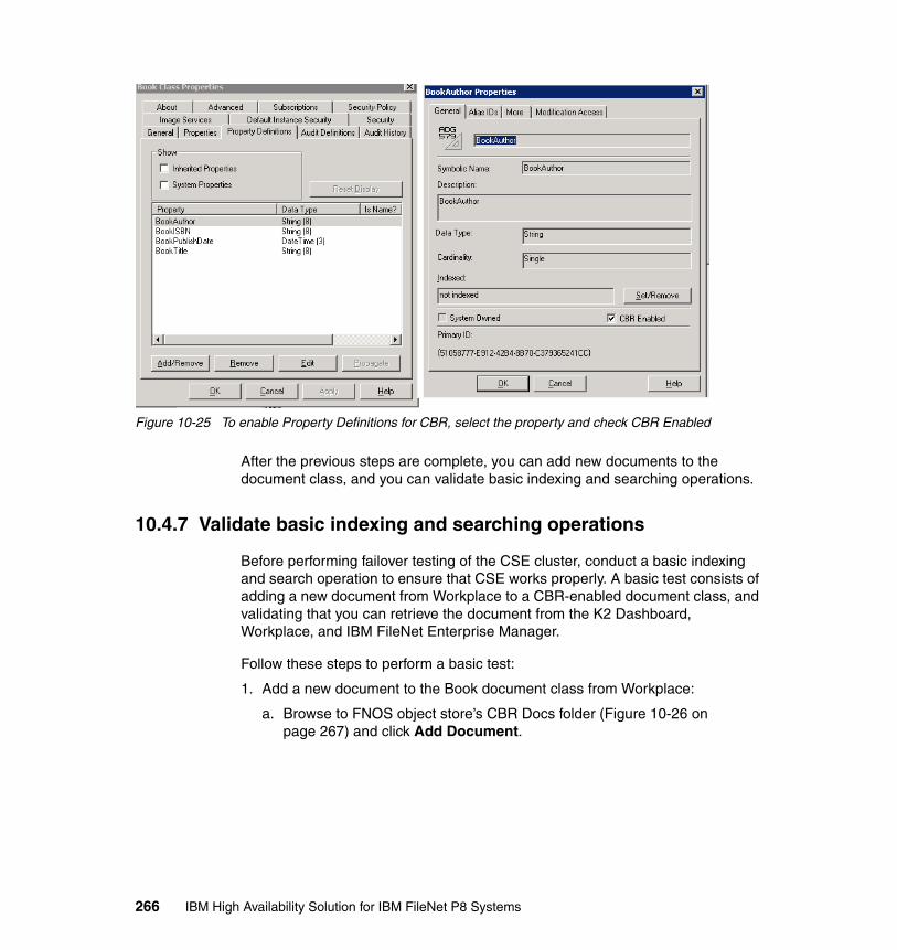
Figure 10-25 To enable Property Definitions for CBR, select the property and check CBR Enabled
After the previous steps are complete, you can add new documents to the document class, and you can validate basic indexing and searching operations.
10.4.7 Validate basic indexing and searching operations
Before performing failover testing of the CSE cluster, conduct a basic indexing and search operation to ensure that CSE works properly. A basic test consists of adding a new document from Workplace to a CBR-enabled document class, and validating that you can retrieve the document from the K2 Dashboard, Workplace, and IBM FileNet Enterprise Manager.
Follow these steps to perform a basic test:
1. Add a new document to the Book document class from Workplace:
a. Browse to FNOS object store’s CBR Docs folder (Figure 10-26 on page 267) and click Add Document.
266 IBM High Availability Solution for IBM FileNet P8 Systems
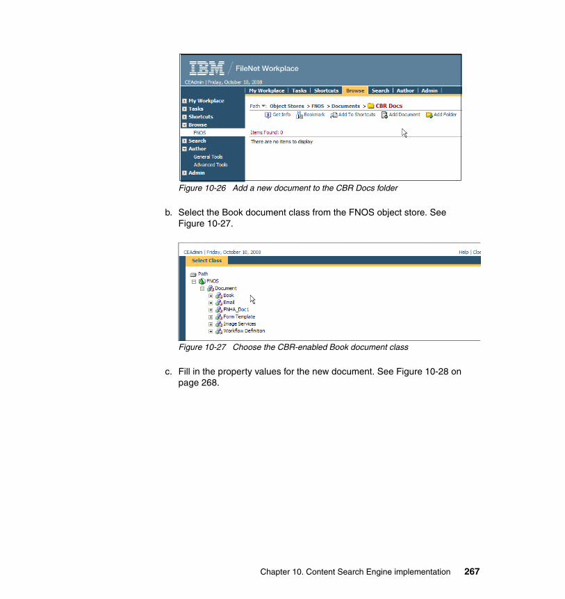
Figure 10-26 Add a new document to the CBR Docs folder
b. Select the Book document class from the FNOS object store. See Figure 10-27.
Figure 10-27 Choose the CBR-enabled Book document class
c. Fill in the property values for the new document. See Figure 10-28 on page 268.
Chapter 10. Content Search Engine implementation 267
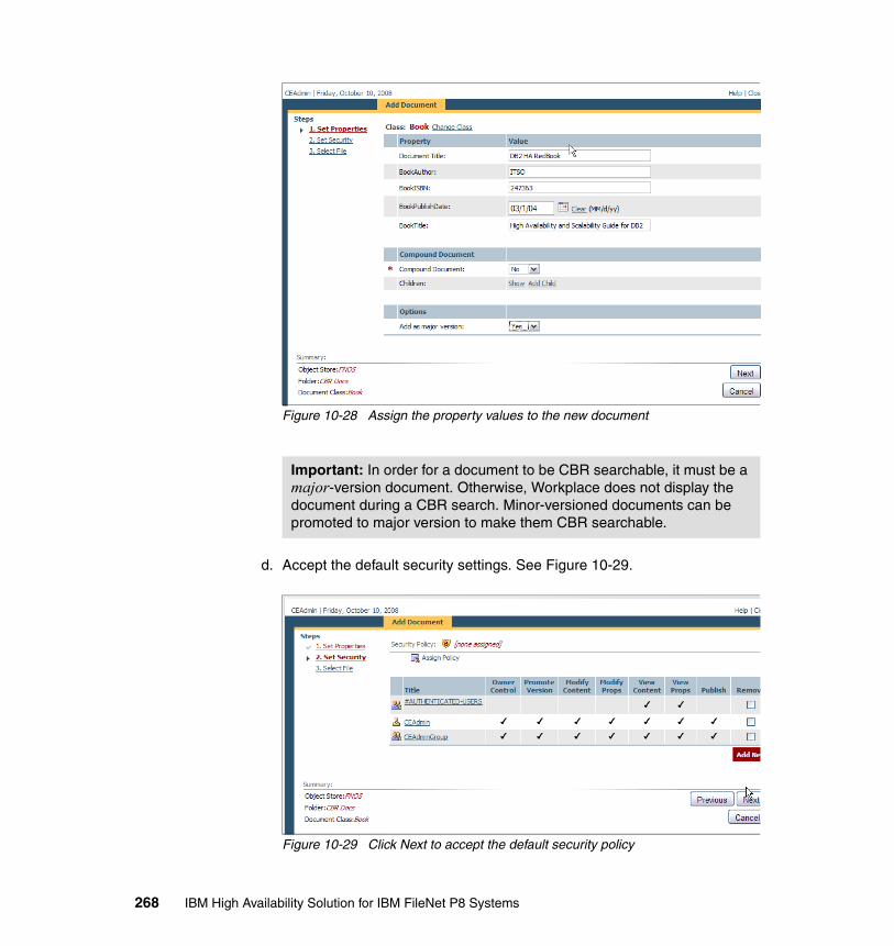
Figure 10-28 Assign the property values to the new document
d. Accept the default security settings. See Figure 10-29.
Figure 10-29 Click Next to accept the default security policy
Important: In order for a document to be CBR searchable, it must be a major-version document. Otherwise, Workplace does not display the document during a CBR search. Minor-versioned documents can be promoted to major version to make them CBR searchable.
268 IBM High Availability Solution for IBM FileNet P8 Systems
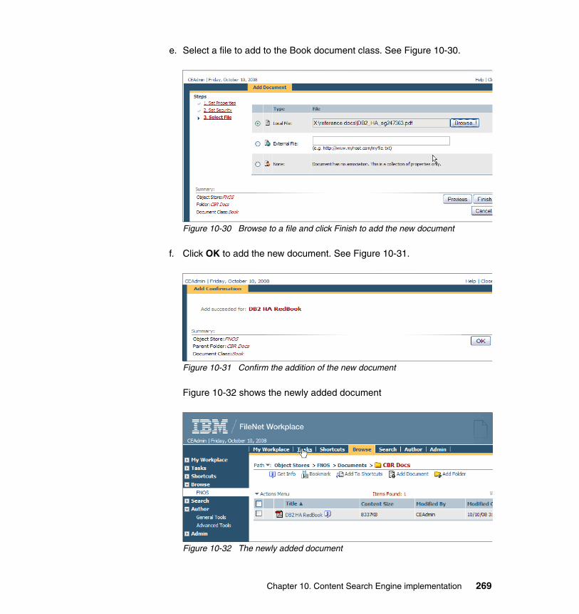
e. Select a file to add to the Book document class. See Figure 10-30.
Figure 10-30 Browse to a file and click Finish to add the new document
f. Click OK to add the new document. See Figure 10-31.
Figure 10-31 Confirm the addition of the new document
Figure 10-32 shows the newly added document
Figure 10-32 The newly added document
Chapter 10. Content Search Engine implementation 269
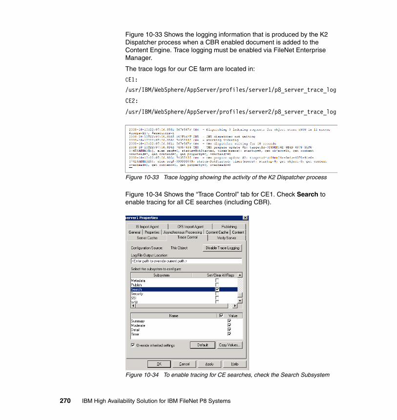
Figure 10-33 Shows the logging information that is produced by the K2 Dispatcher process when a CBR enabled document is added to the Content Engine. Trace logging must be enabled via FileNet Enterprise Manager.
The trace logs for our CE farm are located in:
CE1:
/usr/IBM/WebSphere/AppServer/profiles/server1/p8_server_trace_log
CE2:
/usr/IBM/WebSphere/AppServer/profiles/server2/p8_server_trace_log
Figure 10-33 Trace logging showing the activity of the K2 Dispatcher process
Figure 10-34 Shows the “Trace Control” tab for CE1. Check Search to enable tracing for all CE searches (including CBR).
Figure 10-34 To enable tracing for CE searches, check the Search Subsystem
270 IBM High Availability Solution for IBM FileNet P8 Systems
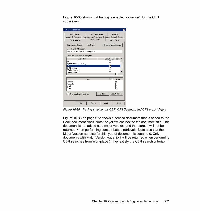
Figure 10-35 shows that tracing is enabled for server1 for the CBR subsystem.
Figure 10-35 Tracing is set for the CBR, CFS Daemon, and CFS Import Agent
Figure 10-36 on page 272 shows a second document that is added to the Book document class. Note the yellow icon next to the document title. This document is not added as a major version, and therefore, it will not be returned when performing content-based retrievals. Note also that the Major Version attribute for this type of document is equal to 0. Only documents with Major Version equal to 1 will be returned when performing CBR searches from Workplace (if they satisfy the CBR search criteria).
Chapter 10. Content Search Engine implementation 271
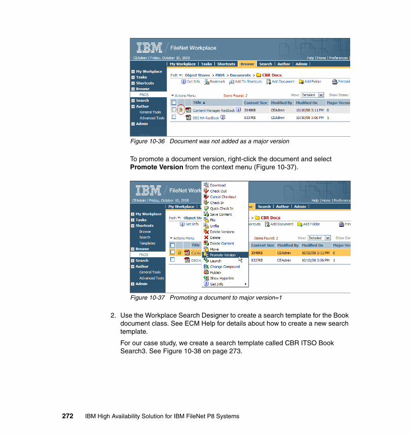
Figure 10-36 Document was not added as a major version
To promote a document version, right-click the document and select Promote Version from the context menu (Figure 10-37).
Figure 10-37 Promoting a document to major version=1
2. Use the Workplace Search Designer to create a search template for the Book document class. See ECM Help for details about how to create a new search template.
For our case study, we create a search template called CBR ITSO Book Search3. See Figure 10-38 on page 273.
272 IBM High Availability Solution for IBM FileNet P8 Systems
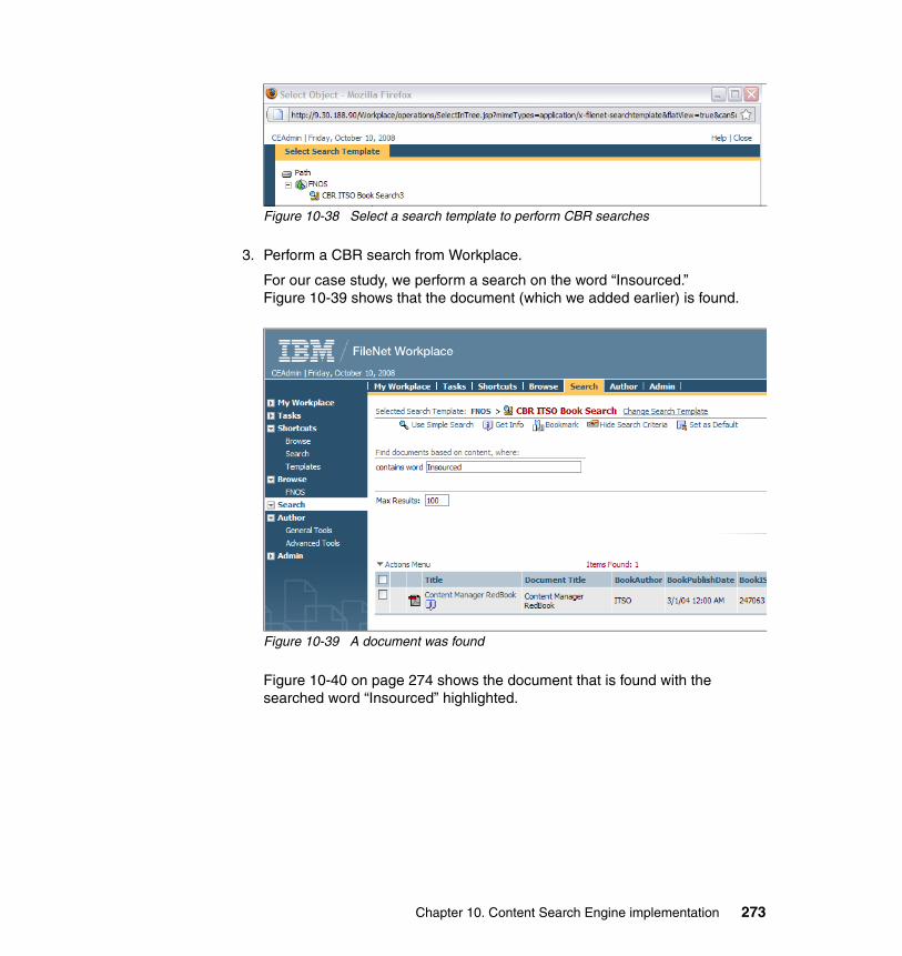
Figure 10-38 Select a search template to perform CBR searches
3. Perform a CBR search from Workplace.
For our case study, we perform a search on the word “Insourced.” Figure 10-39 shows that the document (which we added earlier) is found.
Figure 10-39 A document was found
Figure 10-40 on page 274 shows the document that is found with the searched word “Insourced” highlighted.
Chapter 10. Content Search Engine implementation 273
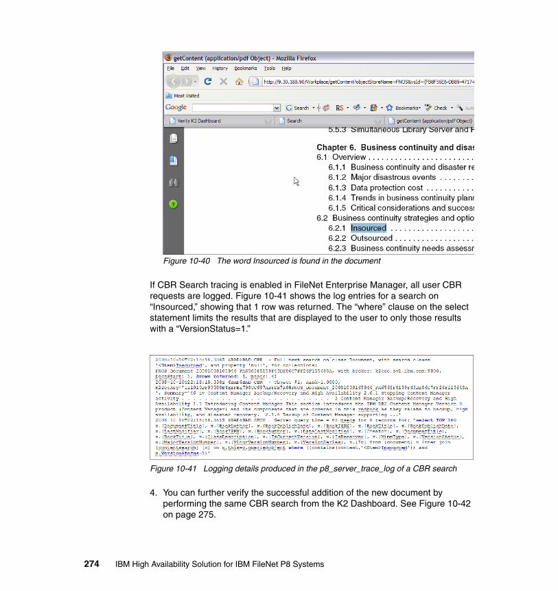
Figure 10-40 The word Insourced is found in the document
If CBR Search tracing is enabled in FileNet Enterprise Manager, all user CBR requests are logged. Figure 10-41 shows the log entries for a search on “Insourced,” showing that 1 row was returned. The “where” clause on the select statement limits the results that are displayed to the user to only those results with a “VersionStatus=1.”
Figure 10-41 Logging details produced in the p8_server_trace_log of a CBR search
4. You can further verify the successful addition of the new document by performing the same CBR search from the K2 Dashboard. See Figure 10-42 on page 275.
274 IBM High Availability Solution for IBM FileNet P8 Systems
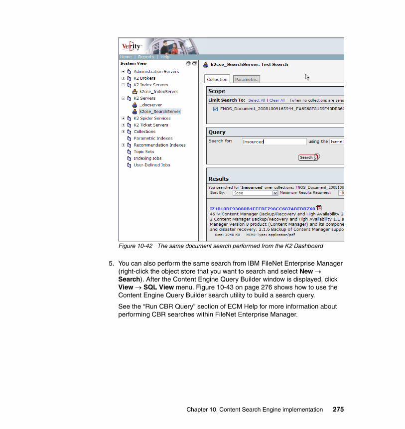
Figure 10-42 The same document search performed from the K2 Dashboard
5. You can also perform the same search from IBM FileNet Enterprise Manager (right-click the object store that you want to search and select New → Search). After the Content Engine Query Builder window is displayed, click View → SQL View menu. Figure 10-43 on page 276 shows how to use the Content Engine Query Builder search utility to build a search query.
See the “Run CBR Query” section of ECM Help for more information about performing CBR searches within FileNet Enterprise Manager.
Chapter 10. Content Search Engine implementation 275
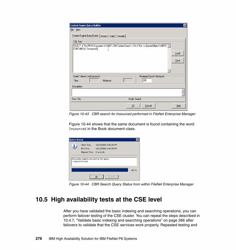
Figure 10-43 CBR search for Insourced performed in FileNet Enterprise Manager
Figure 10-44 shows that the same document is found containing the word Insourced in the Book document class.
Figure 10-44 CBR Search Query Status from within FileNet Enterprise Manager
10.5 High availability tests at the CSE level
After you have validated the basic indexing and searching operations, you can perform failover testing of the CSE cluster. You can repeat the steps described in 10.4.7, “Validate basic indexing and searching operations” on page 266 after failovers to validate that the CSE services work properly. Repeated testing and
276 IBM High Availability Solution for IBM FileNet P8 Systems
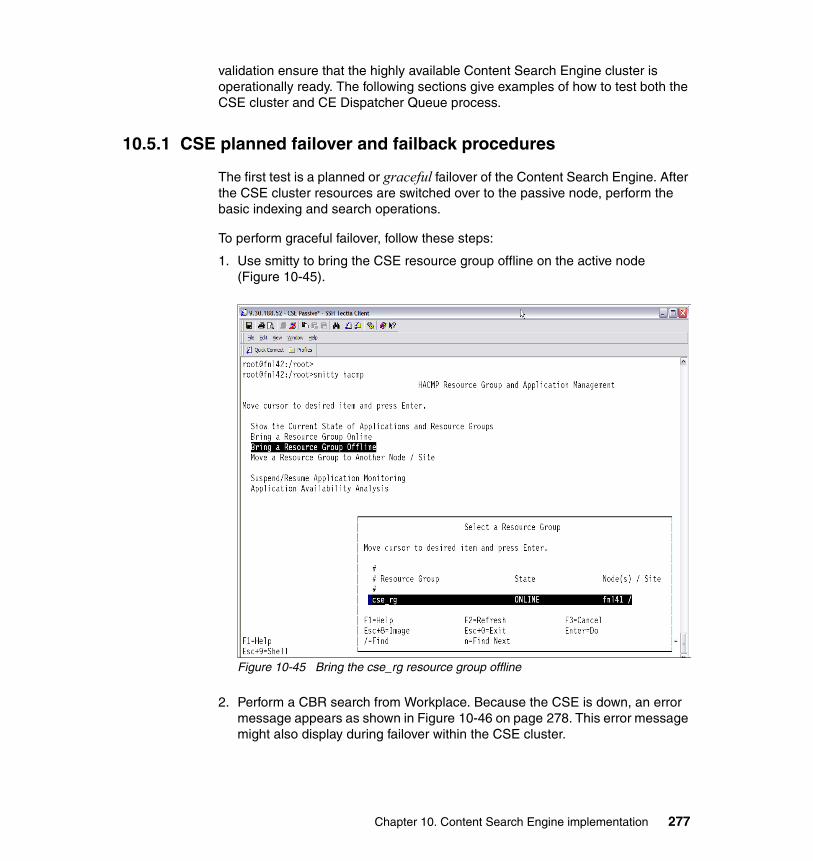
validation ensure that the highly available Content Search Engine cluster is operationally ready. The following sections give examples of how to test both the CSE cluster and CE Dispatcher Queue process.
10.5.1 CSE planned failover and failback procedures
The first test is a planned or graceful failover of the Content Search Engine. After the CSE cluster resources are switched over to the passive node, perform the basic indexing and search operations.
To perform graceful failover, follow these steps:
1. Use smitty to bring the CSE resource group offline on the active node (Figure 10-45).
Figure 10-45 Bring the cse_rg resource group offline
2. Perform a CBR search from Workplace. Because the CSE is down, an error message appears as shown in Figure 10-46 on page 278. This error message might also display during failover within the CSE cluster.
Chapter 10. Content Search Engine implementation 277
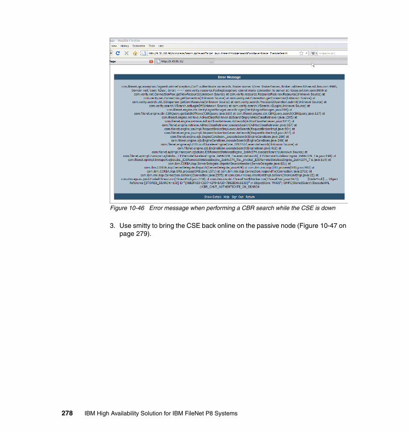
Figure 10-46 Error message when performing a CBR search while the CSE is down
3. Use smitty to bring the CSE back online on the passive node (Figure 10-47 on page 279).
278 IBM High Availability Solution for IBM FileNet P8 Systems

Figure 10-47 Bring the CSE resource group online on the passive node
4. After the CSE resource group is online on the passive node, perform the basic index and search operations to validate the functionality of the Content Search Engine.
5. Use smitty to fail the CSE back to the other node by clicking Move the resource group to another Node / Site. After this task completes, perform the basic search and index operations again.
10.5.2 CSE unplanned failover and failback procedures
Although system failures and cluster takeover tests can be simulated in a number of ways, we provide the following procedure as a starting point for your testing. Conduct an unplanned or ungraceful failure of the CSE by performing the these steps:
1. Force the shutdown of the currently active CSE node without gracefully stopping any running processes or applications:
# sync;sync;sync;reboot -q
Chapter 10. Content Search Engine implementation 279
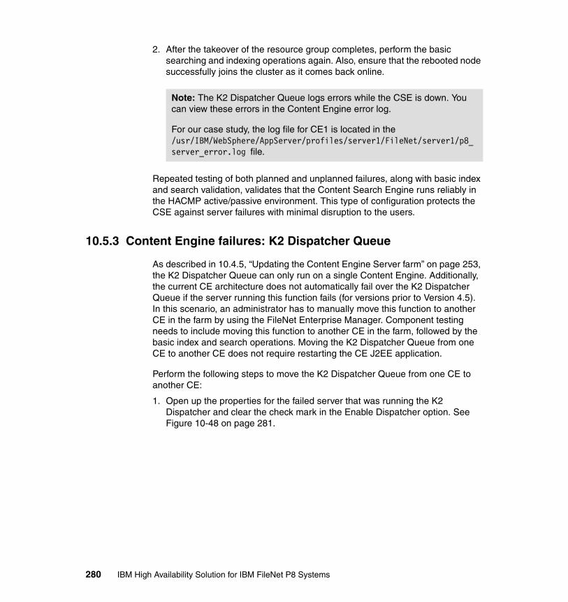
2. After the takeover of the resource group completes, perform the basic searching and indexing operations again. Also, ensure that the rebooted node successfully joins the cluster as it comes back online.
Repeated testing of both planned and unplanned failures, along with basic index and search validation, validates that the Content Search Engine runs reliably in the HACMP active/passive environment. This type of configuration protects the CSE against server failures with minimal disruption to the users.
10.5.3 Content Engine failures: K2 Dispatcher Queue
As described in 10.4.5, “Updating the Content Engine Server farm” on page 253, the K2 Dispatcher Queue can only run on a single Content Engine. Additionally, the current CE architecture does not automatically fail over the K2 Dispatcher Queue if the server running this function fails (for versions prior to Version 4.5). In this scenario, an administrator has to manually move this function to another CE in the farm by using the FileNet Enterprise Manager. Component testing needs to include moving this function to another CE in the farm, followed by the basic index and search operations. Moving the K2 Dispatcher Queue from one CE to another CE does not require restarting the CE J2EE application.
Perform the following steps to move the K2 Dispatcher Queue from one CE to another CE:
1. Open up the properties for the failed server that was running the K2 Dispatcher and clear the check mark in the Enable Dispatcher option. See Figure 10-48 on page 281.
Note: The K2 Dispatcher Queue logs errors while the CSE is down. You can view these errors in the Content Engine error log.
For our case study, the log file for CE1 is located in the /usr/IBM/WebSphere/AppServer/profiles/server1/FileNet/server1/p8_server_error.log file.
280 IBM High Availability Solution for IBM FileNet P8 Systems
Figure 10-48 Deselect the “Enable Dispatcher” check box on the failed CE server
2. Open up the properties for one of the working CE servers in the CE farm, and enable the K2 Dispatcher Queue by selecting the Enable Dispatcher option. Depending on your inherited settings, you might have to select “Override inherited settings” first. After the K2 Dispatcher Queue thread has been enabled, check the CE error log for the following messages:
2008-10-08 09:34:33,312 INFO [CBRDispatcher_FNOS_#9] - Starting CBR queue dispatching for FNOS2008-10-08 09:34:33,314 INFO [CBRDispatcher_FNOS_#9] - FNOS ({A52594C3-3413-4DA5-B406-00F82CC6978A}) is enabled
3. Perform basic index and search operations to ensure that the K2 Dispatcher Queue has successfully migrated.
Chapter 10. Content Search Engine implementation 281

10.6 Troubleshooting the Content Search Engine
This section provides troubleshooting quick references (in no particular order) to use when debugging the CE and the CSE:
� The Autonomy K2 Dashboard URL launches successfully after the k2adminstart script has been run. Example:
http://k2cse.svl.ibm.com:9990/verity_dashboard/main.jsp
� The Autonomy K2 servers (processes) log all of their activity in separate directories. Example:
/opt/verity/data/host/log/status.log/opt/verity/data/services/_docserver/log/status.log/opt/verity/data/k2cse_IndexServer/log/status.log/opt/verity/data/k2cse_TicketServer/log/status.log
� In order to obtain the current version of the CSE client on the Content Engine, run these commands:
$ cd /opt/FileNet/ContentEngine/lib$ cat k2_Version.txt
� The CE server trace and error logs are located in these files:
/usr/IBM/WebSphere/AppServer/profiles/server1/FileNet/server1/p8_server_error.log
/usr/IBM/WebSphere/AppServer/profiles/server1/FileNet/server1/p8_server_trace.log
� In addition to using the K2 Dashboard, you can run the following command line utilities on the CSE to search the collections directories:
$ rcvdk$ rck2
� What if a Workplace search does not return any documents? You might want to ask the following questions:
– Is CSE running on the active node of the cluster?
– Have you waited long enough and adjusted the wait interval?
– Have you enabled CBR on the document class that you are searching?
– Is your collections directory listed in /opt/verity/k2/common/verity.cfg?
– Do you need to re-index?
– Do you see any activity in the CE trace log (tracing must be enabled)?
– Can you perform the same search from the K2 Dashboard?
282 IBM High Availability Solution for IBM FileNet P8 Systems

– Can you perform the same search using the rcdvk command line utility?
– Can you perform the same search from FileNet Enterprise Manager?
– Did you check the K2 Search server log file?
– Are all of the necessary file systems mounted?
Chapter 10. Content Search Engine implementation 283

284 IBM High Availability Solution for IBM FileNet P8 Systems
Chapter 11. Image Services implementation
This chapter describes the high availability options for Image Services (IS) and the requirements for planning and implementing a highly available cluster for IS. In addition, we provide the practical, step-by-step procedures that we use to install IS in an existing IBM PowerHA for AIX cluster. IBM PowerHA for AIX was previously known as IBM High Availability Cluster Multi-Processing (HACMP). We also briefly discuss the required steps to make an existing IS part of a new HACMP cluster.
We discuss the following topics:
� High availability options for Image Services� Installing IS in a high availability environment� High availability test for IS cluster� IS maintenance in HACMP clusters
11
© Copyright IBM Corp. 2009. All rights reserved. 285
11.1 High availability options for Image Services
This section discusses high availability options for Image Services (IS). It describes the prerequisites and the principle of operation of an active/passive high availability cluster with IS.
For an overview of Image Services, refer to 2.5, “Image Services and CFS-IS” on page 32.
11.1.1 High availability for Image Services
IBM FileNet Image Services (IS) stores and manages an enterprise-level volume of fixed content from multiple sources. It can either work stand-alone, or it can represent the base of the Image Manager component of an IBM FileNet P8 system.
Due to the business-critical nature of the content stored on IS systems, demand for high availability (HA) solutions is increasing. IS systems can be made highly available by creating active/passive HA clusters (asymmetric clusters), that is, one cluster server (node) runs IS, while another node is idle standby. If the active node fails, IS is started on the idle standby node. IS systems cannot be farmed for HA purposes, because there can be only one active “Root/Index” server per domain.
An active/passive HA cluster with IS requires the following components:
� Two cluster nodes running a cluster software (for example, HACMP)� Shared storage for IS, as well as Magnetic Storage and Retrieval (MSAR) � A common local or remote database (for example, DB2)� A regular and an additional HA IS license
You create a cluster by installing and configuring high availability cluster software on all participating nodes. When operational, the cluster presents a virtual IP address, which is bound to the currently active cluster node, to the clients. This node is also the owner of all of the resources that are needed to run IS, such as shared disks, IS file systems, and so on.
The HA cluster is useful for planned downtime (maintenance) and for unplanned downtime (for example, due to failure) of a cluster node. The takeover can be initiated manually or automatically in case of a failure.
286 IBM High Availability Solution for IBM FileNet P8 Systems
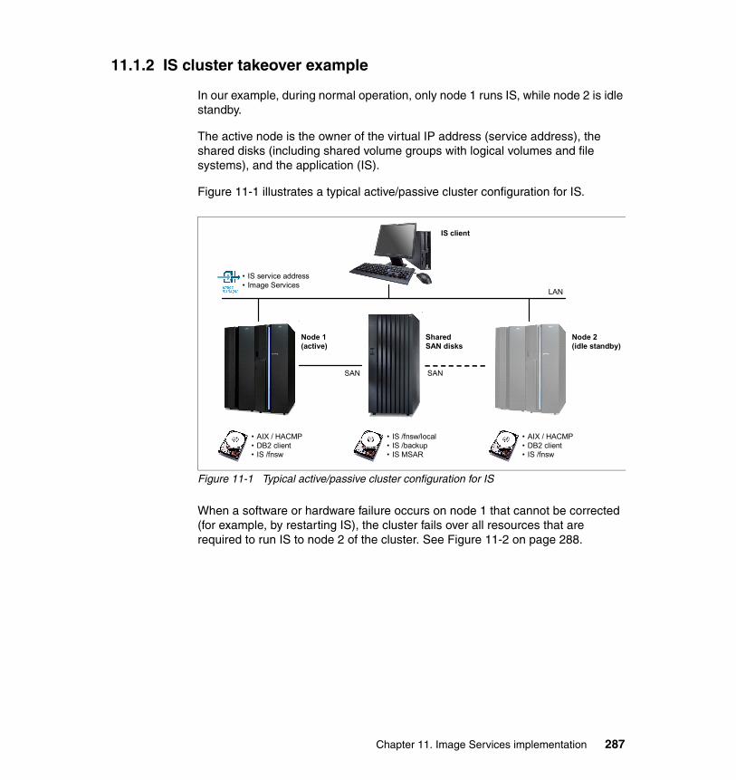
11.1.2 IS cluster takeover example
In our example, during normal operation, only node 1 runs IS, while node 2 is idle standby.
The active node is the owner of the virtual IP address (service address), the shared disks (including shared volume groups with logical volumes and file systems), and the application (IS).
Figure 11-1 illustrates a typical active/passive cluster configuration for IS.
Figure 11-1 Typical active/passive cluster configuration for IS
When a software or hardware failure occurs on node 1 that cannot be corrected (for example, by restarting IS), the cluster fails over all resources that are required to run IS to node 2 of the cluster. See Figure 11-2 on page 288.
• AIX / HACMP• DB2 client• IS /fnsw
• AIX / HACMP• DB2 client• IS /fnsw
• IS /fnsw/local• IS /backup• IS MSAR
SharedSAN disks
Node 1(active)
Node 2(idle standby)
IS client
• IS service address• Image Services
LAN
SAN SAN
Chapter 11. Image Services implementation 287
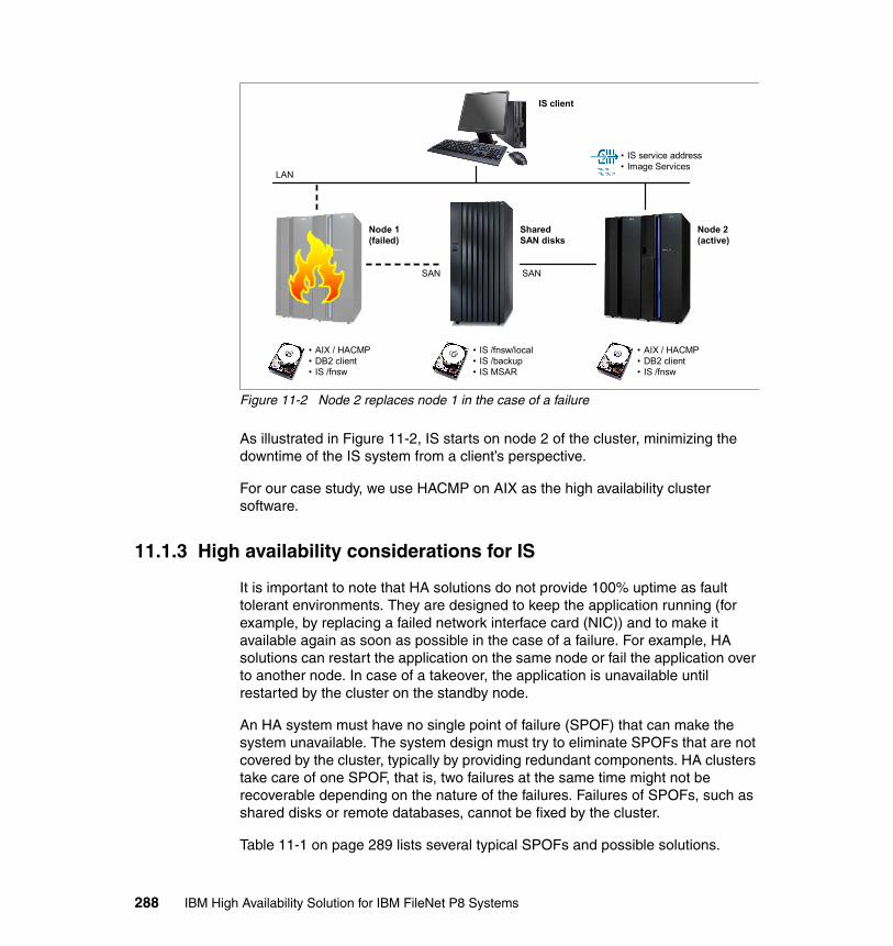
Figure 11-2 Node 2 replaces node 1 in the case of a failure
As illustrated in Figure 11-2, IS starts on node 2 of the cluster, minimizing the downtime of the IS system from a client’s perspective.
For our case study, we use HACMP on AIX as the high availability cluster software.
11.1.3 High availability considerations for IS
It is important to note that HA solutions do not provide 100% uptime as fault tolerant environments. They are designed to keep the application running (for example, by replacing a failed network interface card (NIC)) and to make it available again as soon as possible in the case of a failure. For example, HA solutions can restart the application on the same node or fail the application over to another node. In case of a takeover, the application is unavailable until restarted by the cluster on the standby node.
An HA system must have no single point of failure (SPOF) that can make the system unavailable. The system design must try to eliminate SPOFs that are not covered by the cluster, typically by providing redundant components. HA clusters take care of one SPOF, that is, two failures at the same time might not be recoverable depending on the nature of the failures. Failures of SPOFs, such as shared disks or remote databases, cannot be fixed by the cluster.
Table 11-1 on page 289 lists several typical SPOFs and possible solutions.
• AIX / HACMP• DB2 client• IS /fnsw
• AIX / HACMP• DB2 client• IS /fnsw
• IS /fnsw/local• IS /backup• IS MSAR
SharedSAN disks
Node 1(failed)
Node 2(active)
IS client
• IS service address• Image Services
LAN
SAN SAN
288 IBM High Availability Solution for IBM FileNet P8 Systems
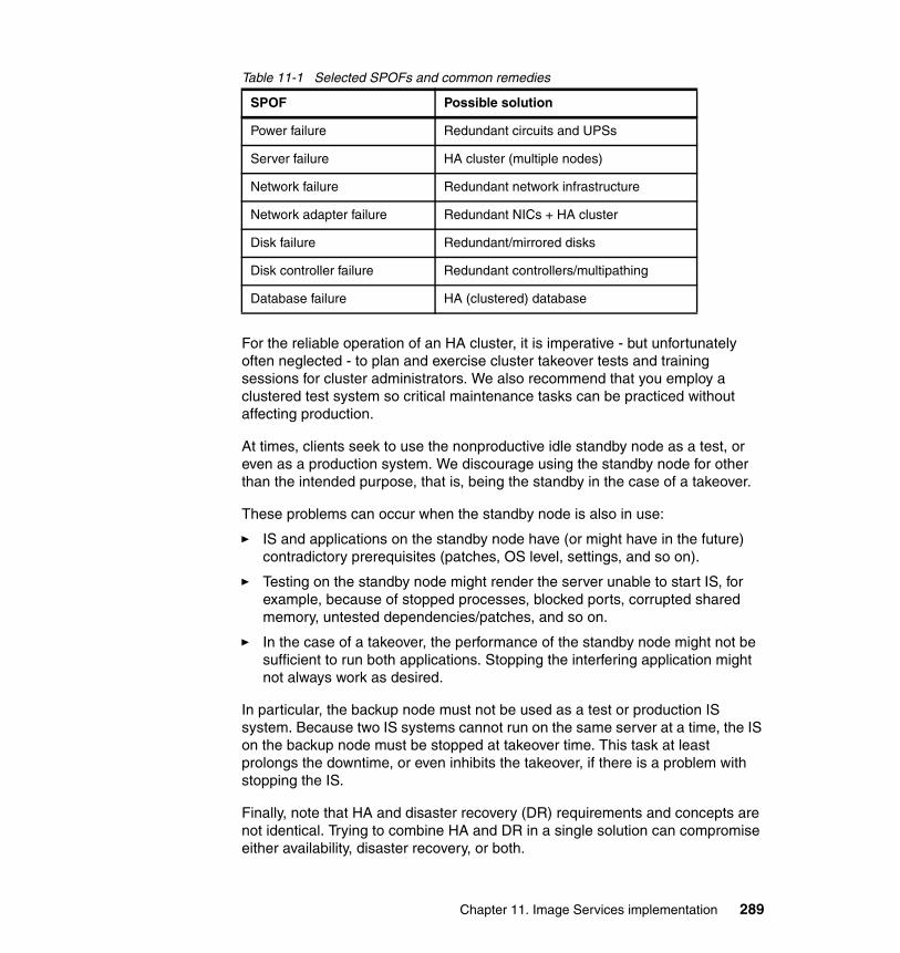
Table 11-1 Selected SPOFs and common remedies
For the reliable operation of an HA cluster, it is imperative - but unfortunately often neglected - to plan and exercise cluster takeover tests and training sessions for cluster administrators. We also recommend that you employ a clustered test system so critical maintenance tasks can be practiced without affecting production.
At times, clients seek to use the nonproductive idle standby node as a test, or even as a production system. We discourage using the standby node for other than the intended purpose, that is, being the standby in the case of a takeover.
These problems can occur when the standby node is also in use:
� IS and applications on the standby node have (or might have in the future) contradictory prerequisites (patches, OS level, settings, and so on).
� Testing on the standby node might render the server unable to start IS, for example, because of stopped processes, blocked ports, corrupted shared memory, untested dependencies/patches, and so on.
� In the case of a takeover, the performance of the standby node might not be sufficient to run both applications. Stopping the interfering application might not always work as desired.
In particular, the backup node must not be used as a test or production IS system. Because two IS systems cannot run on the same server at a time, the IS on the backup node must be stopped at takeover time. This task at least prolongs the downtime, or even inhibits the takeover, if there is a problem with stopping the IS.
Finally, note that HA and disaster recovery (DR) requirements and concepts are not identical. Trying to combine HA and DR in a single solution can compromise either availability, disaster recovery, or both.
SPOF Possible solution
Power failure Redundant circuits and UPSs
Server failure HA cluster (multiple nodes)
Network failure Redundant network infrastructure
Network adapter failure Redundant NICs + HA cluster
Disk failure Redundant/mirrored disks
Disk controller failure Redundant controllers/multipathing
Database failure HA (clustered) database
Chapter 11. Image Services implementation 289
11.2 Installing IS in a high availability environment
This section describes the steps that are necessary to install IS in an existing HACMP cluster for the case study that we set up for this book. We also briefly describe the steps to make an existing IS part of a new HACMP cluster.
11.2.1 IS HA support and documentation
Image Services provides documentation and support for Microsoft Cluster Service (MSCS) and Veritas Cluster Server (VCS). Clients have also successfully implemented IS on IBM HACMP (AIX) clusters, Sun Solaris Cluster (Solaris), and HP Serviceguard (HP-UX).
We recommend the following IS documentation that we used for this project:
� IBM FileNet Image Services, Version 4.1, Microsoft Cluster Server Installation and Upgrade Procedures for Windows Server, GC31-5531-01
� IBM FileNet Image Services, Version 4.1, VERITAS Cluster Server and VERITAS Volume Replicator Guidelines, GC31-5545
� IBM FileNet Image Services, Version 4.1, Installation and Configuration Procedures for AIX/6000, GC31-5557-01
� IBM FileNet Image Services, Version 4.1, Release Notes, GC31-5578-03
� IBM FileNet P8 Content Federation Services for Image Services, Version 4.0, Guidelines, GC31-5484-01
� IBM FileNet Image Services, Hardware and Software Requirements, GC31-5609-04
� IBM FileNet Image Services, OSAR Cable Tool, 2008-07-22
IS by itself is not “cluster-aware,” that is, IS does not directly communicate with the cluster software. It can, however, be easily integrated into HA clusters as a “Generic Service” (MSCS) or by means of start, stop, and monitor scripts.
IS has been designed to run in HA cluster environments. Provisions have been made so that current logons are carried over and “most” users stay connected during a cluster takeover. Certain processes require logging in again (for example, current IDM Find queries) or require the user to repeat the last work performed (for example, re-scan the last batch with Capture Professional). Recent upgrade wizards for installing IS patches and release updates support updating the second node of an IS cluster.
IS supports (as of IS Version 4.1.2) remote clustered databases. Previous versions were unable to reconnect to the database if it had been restarted or if a
290 IBM High Availability Solution for IBM FileNet P8 Systems

remote clustered database had failed over to another node. Only “combined” IS Servers (Root-Index-MSAR/Optical Storage and Retrieval (OSAR) are supported with HA clusters. Any additional application server needs to be restarted whenever the Root/Index server is started or fails over to another cluster node, which prolongs the takeover and endangers the availability of the IS system.
To find a suitable and supported HA configuration for IS, consult the IS IBM FileNet Image Services, Version 4.1, Installation and Configuration Procedures for AIX/6000, GC31-5557-01, IBM FileNet Image Services, ISRA, and Print Hardware and Software Requirements, GC31-5609-04, and the IBM FileNet Image Services, OSAR Cable Tool, 2008-07-22. The IS IBM FileNet Image Services, Version 4.1, Release Notes, GC31-5578-03, IBM FileNet Image Services, Version 4.1, Microsoft Cluster Server Installation and Upgrade Procedures for Windows Server, GC31-5531-01, and IBM FileNet Image Services, Version 4.1, VERITAS Cluster Server and VERITAS Volume Replicator Guidelines, GC31-5545, also contain valuable information regarding supported configurations.
Note these support limitations:
� Maximum number of cluster nodes (currently, two)� Combined or dual-server IS (currently, combined only)� Local or remote database (for example, DB2 remote only)� Support of virtualization technologies (for example, logical partition (LPAR)
with MSAR only)
For this case study, we choose a two-node HACMP cluster with a remote (clustered) DB2 database.
11.2.2 Fresh installation of IS on HACMP
The installation of IS on the HACMP cluster follows these steps:
1. Plan the system layout and parameters.
2. Verify the prerequisites and cluster resources.
3. Install the DB2 client on node 1.
4. Install the general availability (GA) IS, IS Service Pack (SP), and IS Fix Pack (FP) on node 1.
5. Switch cluster resources over to cluster node 2.
6. Install the DB2 client on node 2.
7. Install the GA IS, IS SP, and IS FP on node 2.
8. Test the IS installation and cluster takeover behavior.
Chapter 11. Image Services implementation 291
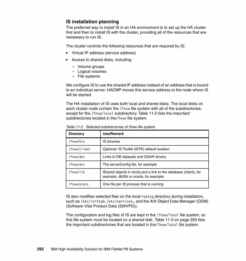
IS installation planningThe preferred way to install IS in an HA environment is to set up the HA cluster first and then to install IS with the cluster, providing all of the resources that are necessary to run IS.
The cluster controls the following resources that are required by IS:
� Virtual IP address (service address)
� Access to shared disks, including:
– Volume groups– Logical volumes– File systems
We configure IS to use the shared IP address instead of an address that is bound to an individual server. HACMP moves this service address to the node where IS will be started.
The HA installation of IS uses both local and shared disks. The local disks on each cluster node contain the /fnsw file system with all of the subdirectories, except for the /fnsw/local subdirectory. Table 11-2 lists the important subdirectories located in the/fnsw file system.
Table 11-2 Selected subdirectories of /fnsw file system
IS also modifies selected files on the local rootvg directory during installation, such as /etc/inittab, /etc/services, and the AIX Object Data Manager (ODM) (Software Vital Product Data (SWVPD)).
The configuration and log files of IS are kept in the /fnsw/local file system, so this file system must be located on a shared disk. Table 11-3 on page 293 lists the important subdirectories that are located in the/fnsw/local file system.
Directory Use/Remark
/fnsw/bin IS binaries
/fnsw/client Optional: IS Toolkit (ISTK) default location
/fnsw/dev Links to DB datasets and OSAR drivers
/fnsw/etc The serverConfig file, for example
/fnsw/lib Shared objects in shobj and a link to the database (client), for example, db2lib or oracle, for example
/fnsw/procs One file per IS process that is running
292 IBM High Availability Solution for IBM FileNet P8 Systems
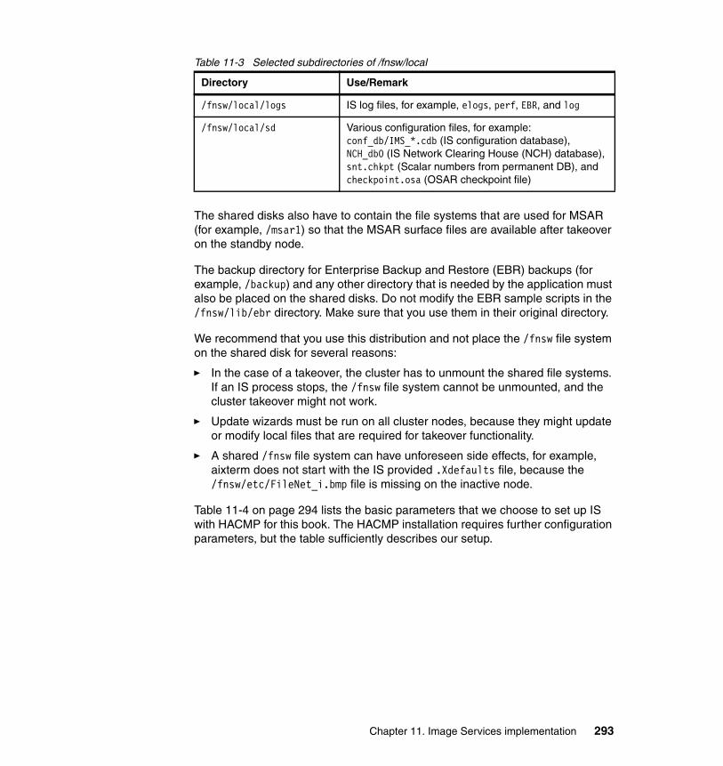
Table 11-3 Selected subdirectories of /fnsw/local
The shared disks also have to contain the file systems that are used for MSAR (for example, /msar1) so that the MSAR surface files are available after takeover on the standby node.
The backup directory for Enterprise Backup and Restore (EBR) backups (for example, /backup) and any other directory that is needed by the application must also be placed on the shared disks. Do not modify the EBR sample scripts in the /fnsw/lib/ebr directory. Make sure that you use them in their original directory.
We recommend that you use this distribution and not place the /fnsw file system on the shared disk for several reasons:
� In the case of a takeover, the cluster has to unmount the shared file systems. If an IS process stops, the /fnsw file system cannot be unmounted, and the cluster takeover might not work.
� Update wizards must be run on all cluster nodes, because they might update or modify local files that are required for takeover functionality.
� A shared /fnsw file system can have unforeseen side effects, for example, aixterm does not start with the IS provided .Xdefaults file, because the /fnsw/etc/FileNet_i.bmp file is missing on the inactive node.
Table 11-4 on page 294 lists the basic parameters that we choose to set up IS with HACMP for this book. The HACMP installation requires further configuration parameters, but the table sufficiently describes our setup.
Directory Use/Remark
/fnsw/local/logs IS log files, for example, elogs, perf, EBR, and log
/fnsw/local/sd Various configuration files, for example:conf_db/IMS_*.cdb (IS configuration database),NCH_db0 (IS Network Clearing House (NCH) database),snt.chkpt (Scalar numbers from permanent DB), and checkpoint.osa (OSAR checkpoint file)
Chapter 11. Image Services implementation 293
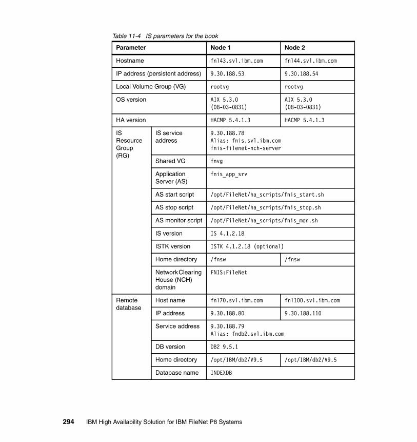
Table 11-4 IS parameters for the book
Parameter Node 1 Node 2
Hostname fnl43.svl.ibm.com fnl44.svl.ibm.com
IP address (persistent address) 9.30.188.53 9.30.188.54
Local Volume Group (VG) rootvg rootvg
OS version AIX 5.3.0 (08-03-0831)
AIX 5.3.0 (08-03-0831)
HA version HACMP 5.4.1.3 HACMP 5.4.1.3
IS Resource Group (RG)
IS service address
9.30.188.78Alias: fnis.svl.ibm.com fnis-filenet-nch-server
Shared VG fnvg
Application Server (AS)
fnis_app_srv
AS start script /opt/FileNet/ha_scripts/fnis_start.sh
AS stop script /opt/FileNet/ha_scripts/fnis_stop.sh
AS monitor script /opt/FileNet/ha_scripts/fnis_mon.sh
IS version IS 4.1.2.18
ISTK version ISTK 4.1.2.18 (optional)
Home directory /fnsw /fnsw
Network Clearing House (NCH) domain
FNIS:FileNet
Remote database
Host name fnl70.svl.ibm.com fnl100.svl.ibm.com
IP address 9.30.188.80 9.30.188.110
Service address 9.30.188.79Alias: fndb2.svl.ibm.com
DB version DB2 9.5.1
Home directory /opt/IBM/db2/V9.5 /opt/IBM/db2/V9.5
Database name INDEXDB
294 IBM High Availability Solution for IBM FileNet P8 Systems

All cluster nodes must be on the same software level, that is, AIX, HACMP, DB2 client, and IS/ISTK must be the same version, including patch levels.
Although we definitely recommend identical cluster nodes (from a hardware perspective), the cluster nodes are not required to be completely identical unless an OSAR is connected to the cluster. In that case, the Small Computer System Interface (SCSI) adapters that are used on all nodes must provide the exact same hardware path (bus, slot, and so on). Otherwise, the OSAR is recognized as a separate library on each cluster node. Changing the IS configuration (Configuration Database (CDB)) during takeovers is not supported and is a risk to the availability of IS on the standby node.
It is extremely important that the user ID (UID) and group ID (GID) of the IS application owner (fnsw) are identical on both cluster nodes. If the IDs are not identical, IS will not work properly after a takeover, because it is no longer the owner and, therefore, cannot access its own files.
Cluster configuration for ISBefore the IS installation starts, you must configure the cluster resources and make them available. The HACMP Resource Group (RG) controls the service address and the shared volume group with the raw logical volumes and file systems. The IS installation also requires common users and groups and a local /fnsw file system on each of the cluster nodes.
HACMP resource groupWe configure the HACMP cluster to provide the resources required to run IS as shown in Table 11-5.
Table 11-5 HACMP configuration for IS
HACMP parameter Book lab installation
Resource group (RG) fnis_rg
Participating nodes fnl43 fnl44
Service address 9.30.188.78
Application server (AS) fnis_app_srv
AS start script /opt/FileNet/ha_scripts/fnis_start.sh
AS stop script /opt/FileNet/ha_scripts/fnis_stop.sh
AS monitor script /opt/FileNet/ha_scripts/fnis_mon.sh
Volume group (VG) fnvg
Chapter 11. Image Services implementation 295
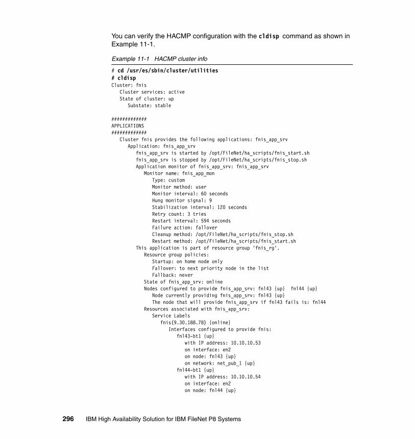
You can verify the HACMP configuration with the cldisp command as shown in Example 11-1.
Example 11-1 HACMP cluster info
# cd /usr/es/sbin/cluster/utilities# cldispCluster: fnis Cluster services: active State of cluster: up Substate: stable
#############APPLICATIONS############# Cluster fnis provides the following applications: fnis_app_srv Application: fnis_app_srv fnis_app_srv is started by /opt/FileNet/ha_scripts/fnis_start.sh fnis_app_srv is stopped by /opt/FileNet/ha_scripts/fnis_stop.sh Application monitor of fnis_app_srv: fnis_app_srv Monitor name: fnis_app_mon Type: custom Monitor method: user Monitor interval: 60 seconds Hung monitor signal: 9 Stabilization interval: 120 seconds Retry count: 3 tries Restart interval: 594 seconds Failure action: fallover Cleanup method: /opt/FileNet/ha_scripts/fnis_stop.sh Restart method: /opt/FileNet/ha_scripts/fnis_start.sh This application is part of resource group 'fnis_rg'. Resource group policies: Startup: on home node only Fallover: to next priority node in the list Fallback: never State of fnis_app_srv: online Nodes configured to provide fnis_app_srv: fnl43 {up} fnl44 {up} Node currently providing fnis_app_srv: fnl43 {up} The node that will provide fnis_app_srv if fnl43 fails is: fnl44 Resources associated with fnis_app_srv: Service Labels fnis(9.30.188.78) {online} Interfaces configured to provide fnis: fnl43-bt1 {up} with IP address: 10.10.10.53 on interface: en2 on node: fnl43 {up} on network: net_pub_1 {up} fnl44-bt1 {up} with IP address: 10.10.10.54 on interface: en2 on node: fnl44 {up}
296 IBM High Availability Solution for IBM FileNet P8 Systems

on network: net_pub_1 {up} Shared Volume Groups: fnvg
#############TOPOLOGY############# fnis consists of the following nodes: fnl43 fnl44 fnl43 Network interfaces: fnl43_vpath0_01 {up} device: /dev/vpath0 on network: net_diskhb_01 {up} fnl43-hs03 {up} with IP address: 10.0.3.53 on interface: en3 on network: net_priv_1 {up} fnl43-bt1 {up} with IP address: 10.10.10.53 on interface: en2 on network: net_pub_1 {up} fnl44 Network interfaces: fnl44_vpath0_01 {up} device: /dev/vpath0 on network: net_diskhb_01 {up} fnl44-hs03 {up} with IP address: 10.0.3.54 on interface: en3 on network: net_priv_1 {up} fnl44-bt1 {up} with IP address: 10.10.10.54 on interface: en2 on network: net_pub_1 {up}
You can use these additional commands to view the HACMP cluster configuration and status:
� /usr/es/sbin/cluster/utilities/cltopinfo� /usr/es/sbin/cluster/utilities/cllsres� /usr/es/sbin/cluster/utilities/clshowres� /usr/es/sbin/cluster/clstat -ao� /usr/es/sbin/cluster/utilities/clRGinfo -v� /usr/es/sbin/cluster/utilities/clRGinfo -m
Chapter 11. Image Services implementation 297

For the installation of IS, we disable all application server (AS) scripts on both nodes by adding exit 0 as the second line of the following scripts. The first line must be the shebang (“#!”), which is the magic number of shell scripts. The monitor script fails if you use anything else for the first line, for example, exit 0.
See Example 11-2 on page 298:
� /opt/FileNet/ha_scripts/fnis_start.sh� /opt/FileNet/ha_scripts/fnis_stop.sh� /opt/FileNet/ha_scripts/fnis_mon.sh
The scripts are not required and actually cause problems during installation. If the scripts do not exist, you must create them later when IS is completely installed.
Example 11-2 Disabled AS scripts for IS installation
#!/bin/kshexit 0[...]
Users and groupsThe ID of the IS groups (GID) and users (UID) must be identical on all cluster nodes. You can create the users and groups by using Cluster-Single Point Of Control (C-SPOC) to achieve the uniqueness of the IDs on both cluster nodes. It is a good practice to choose one of the cluster nodes for all HACMP-related changes and to synchronize the cluster “one way” only at all times.
To add the group and user ID, using smitty:
# smitty hacmp
Click System Management (C-SPOC) → HACMP Security and Users Management → Groups in an HACMP cluster → Add a Group to the Cluster.
You must leave the Group ID field blank to have C-SPOC generate the ID.
Click System Management (C-SPOC) → HACMP Security and Users Management → Users in an HACMP cluster → Add a User to the Cluster.
You must leave the User ID field blank to have C-SPOC generate the ID.
Alternatively, you can create the groups and users manually on each node with specific unique IDs that are not used on any node. See Example 11-3.
298 IBM High Availability Solution for IBM FileNet P8 Systems

Example 11-3 Manual creation of users and groups
# cut -d ":" -f 3 /etc/group | sort -n[...]2112124294967294
# lsgroup -a id ALL | awk '$2~"id=300|id=301|id=302" {print $1}'No groups returned: GIDs 300-302 are available on this node
# mkgroup id=300 fnusr# mkgroup id=301 fnop# mkgroup id=302 fnadmin
# cut -d ":" -f 3 /etc/passwd | sort -n[...]2272284294967294
# lsuser -a id ALL | awk '$2~"id=300" {print $1}'No users returned: UID 300 is available in this node
# mkuser pgrp=fnusr groups=fnadmin,fnop home=/home/fnsw gecos="FileNet IS Admin" id=300 fnsw
Also, you must make the user root (UID 0) part of the newly created fnusr and fnadmin groups.
IS service addressThe IS service address is configured as an IP alias, which HACMP IP address takeover (IPAT) moves together with the IS resource group.
IPAT using IP aliases is the default when HACMP networks are configured in SMIT, for example, the public network, that is shared with the clients:
# smitty hacmp
Click Extended Configuration → Extended Topology Configuration → Configure HACMP Networks → Change/Show a Network in the HACMP Cluster.
Enter these values:
� Network Name: net_pub_1
Chapter 11. Image Services implementation 299

� Network Type: ether� Netmask: 255.255.255.0� Enable IP Address Takeover via IP Aliases: Yes� Network attribute: Public
IPAT using IP aliasing is faster and more reliable with cluster takeovers than IPAT using IP address replacement. However, IPAT using IP address replacement is required with certain types of networks that cannot process Address Resolution Protocol (ARP) cache updates and that require a Hardware Address Takeover (HWAT) of the NIC’s hardware or Media Access Control (MAC) address. HWAT was often used with the old IS client, WorkForce Desktop (WFD). For descriptions of the two types of IPAT, refer to HACMP for AIX, Planning Guide, Version 5.4.1, SC23-4861-10.
With IPAT using IP aliasing, the IS service address alias (9.30.188.78) can be brought up on any of the boot interfaces that are defined for the cluster. If the current network interface card (NIC) fails, HACMP will move the alias with an adapter swap to another interface. If the whole node fails, HACMP will move the alias as part of the resource group to the standby node. Example 11-4 shows the IS service address (9.30.188.78) as an alias to the boot interface en2 of node fnl43.
Example 11-4 IS service address as an IP alias
# ifconfig en2en2: flags=1e080863,480<UP,BROADCAST,NOTRAILERS,RUNNING,SIMPLEX,MULTICAST,GROUPRT,64BIT,CHECKSUM_OFFLOAD(ACTIVE),CHAIN> inet 10.10.10.53 netmask 0xffffff00 broadcast 10.10.10.255 inet 9.30.188.53 netmask 0xffffff00 broadcast 9.30.188.255 inet 9.30.188.78 netmask 0xffffff00 broadcast 9.30.188.255 tcp_sendspace 262144 tcp_recvspace 262144 rfc1323 1
Local file system /fnswWe create the /fnsw file system with 1 GB in the local rootvg directory on each cluster node as shown in Example 11-5.
Example 11-5 Creation of local /fnsw file system
# lsvg rootvg | grep "PP SIZE"VG STATE: active PP SIZE: 128 megabyte(s)
# mklv -y fn_fnsw -t jfs2 rootvg 8 # 8PP*128MB/PP=1GBfn_fnsw
300 IBM High Availability Solution for IBM FileNet P8 Systems

# crfs -v jfs2 -d fn_fnsw -m /fnsw -Ay -p rw -a agblksize=4096File system created successfully.1048340 kilobytes total disk space.New File System size is 2097152
# mount /fnsw
Shared volume group fnvgThe shared volume group (VG) fnvg was created as an “enhance concurrent capable” volume group on shared storage area network (SAN) disks to speed up the takeover process. A unique major number (100) was chosen for the VG to enable NFS mounts on this VG in the HACMP cluster. An identical free major number was determined on all cluster nodes by issuing lvlstmajor on each node.
Example 11-6 shows that major number 50 is used, but for example, 100 is available on this node.
Example 11-6 Querying available major numbers on each node
# cd /etc# lvlstmajor39..49,51...
The VG can be simultaneously created on both cluster nodes using C-SPOC:
# smitty hacmp
Click System Management (C-SPOC) → HACMP Concurrent Logical Volume Management → Concurrent Volume Groups → Create a Concurrent Volume Group.
Enter these values:
� Node Names: fnl43 and fnl44� VOLUME GROUP name: fnvg� Physical partition SIZE in megabytes: 256� Volume group MAJOR NUMBER: 100� Enhanced Concurrent Mode: True
After creation, we turn off the Quorum and change the VG, so it does not automatically vary on when the server is started. HACMP takes care of the
Note: Do not forget to mount /fnsw immediately on each cluster node. Otherwise, the /fnsw/local mount point will be created in the / (root) file system later, not in /fnsw.
Chapter 11. Image Services implementation 301
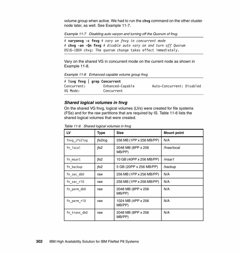
volume group when active. We had to run the chvg command on the other cluster node later, as well. See Example 11-7.
Example 11-7 Disabling auto varyon and turning off the Quorum of fnvg
# varyonvg -c fnvg # vary on fnvg in concurrent mode# chvg -an -Qn fnvg # disable auto vary on and turn off Quorum0516-1804 chvg: The quorum change takes effect immediately.
Vary on the shared VG in concurrent mode on the current node as shown in Example 11-8.
Example 11-8 Enhanced capable volume group fnvg
# lsvg fnvg | grep ConcurrentConcurrent: Enhanced-Capable Auto-Concurrent: DisabledVG Mode: Concurrent
Shared logical volumes in fnvgOn the shared VG fnvg, logical volumes (LVs) were created for file systems (FSs) and for the raw partitions that are required by IS. Table 11-6 lists the shared logical volumes that were created.
Table 11-6 Shared logical volumes in fnvg
LV Type Size Mount point
fnvg_jfs2log jfs2log 256 MB (1PP x 256 MB/PP) N/A
fn_local jfs2 2048 MB (8PP x 256 MB/PP)
/fnsw/local
fn_msar1 jfs2 10 GB (40PP x 256 MB/PP) /msar1
fn_backup jfs2 5 GB (20PP x 256 MB/PP) /backup
fn_sec_db0 raw 256 MB (1PP x 256 MB/PP) N/A
fn_sec_rl0 raw 256 MB (1PP x 256 MB/PP) N/A
fn_perm_db0 raw 2048 MB (8PP x 256 MB/PP)
N/A
fn_perm_rl0 raw 1024 MB (4PP x 256 MB/PP)
N/A
fn_trans_db0 raw 2048 MB (8PP x 256 MB/PP)
N/A
302 IBM High Availability Solution for IBM FileNet P8 Systems
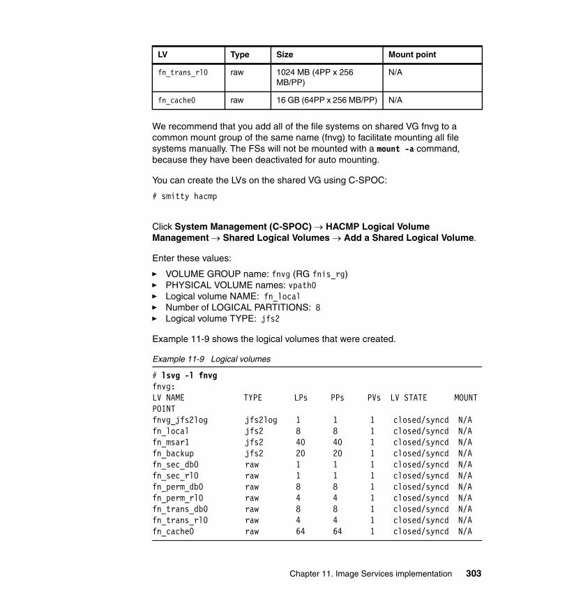
We recommend that you add all of the file systems on shared VG fnvg to a common mount group of the same name (fnvg) to facilitate mounting all file systems manually. The FSs will not be mounted with a mount -a command, because they have been deactivated for auto mounting.
You can create the LVs on the shared VG using C-SPOC:
# smitty hacmp
Click System Management (C-SPOC) → HACMP Logical Volume Management → Shared Logical Volumes → Add a Shared Logical Volume.
Enter these values:
� VOLUME GROUP name: fnvg (RG fnis_rg)� PHYSICAL VOLUME names: vpath0� Logical volume NAME: fn_local� Number of LOGICAL PARTITIONS: 8� Logical volume TYPE: jfs2
Example 11-9 shows the logical volumes that were created.
Example 11-9 Logical volumes
# lsvg -l fnvgfnvg:LV NAME TYPE LPs PPs PVs LV STATE MOUNT POINTfnvg_jfs2log jfs2log 1 1 1 closed/syncd N/Afn_local jfs2 8 8 1 closed/syncd N/Afn_msar1 jfs2 40 40 1 closed/syncd N/Afn_backup jfs2 20 20 1 closed/syncd N/Afn_sec_db0 raw 1 1 1 closed/syncd N/Afn_sec_rl0 raw 1 1 1 closed/syncd N/Afn_perm_db0 raw 8 8 1 closed/syncd N/Afn_perm_rl0 raw 4 4 1 closed/syncd N/Afn_trans_db0 raw 8 8 1 closed/syncd N/Afn_trans_rl0 raw 4 4 1 closed/syncd N/Afn_cache0 raw 64 64 1 closed/syncd N/A
fn_trans_rl0 raw 1024 MB (4PP x 256 MB/PP)
N/A
fn_cache0 raw 16 GB (64PP x 256 MB/PP) N/A
LV Type Size Mount point
Chapter 11. Image Services implementation 303
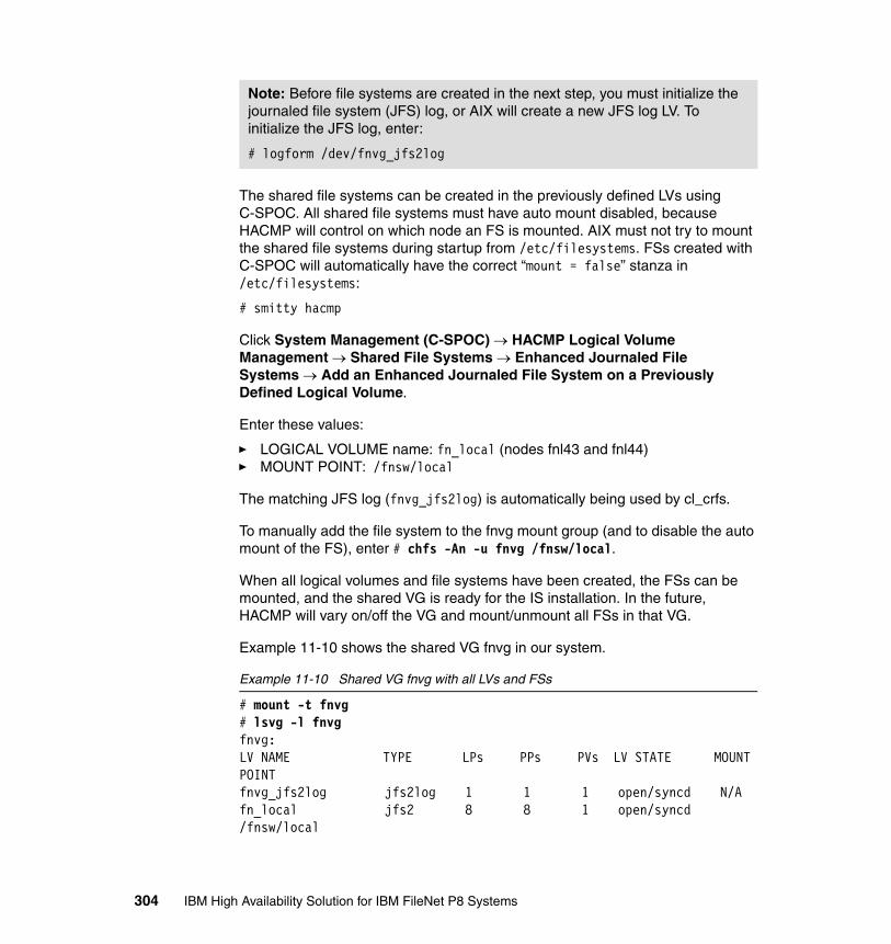
The shared file systems can be created in the previously defined LVs using C-SPOC. All shared file systems must have auto mount disabled, because HACMP will control on which node an FS is mounted. AIX must not try to mount the shared file systems during startup from /etc/filesystems. FSs created with C-SPOC will automatically have the correct “mount = false” stanza in /etc/filesystems:
# smitty hacmp
Click System Management (C-SPOC) → HACMP Logical Volume Management → Shared File Systems → Enhanced Journaled File Systems → Add an Enhanced Journaled File System on a Previously Defined Logical Volume.
Enter these values:
� LOGICAL VOLUME name: fn_local (nodes fnl43 and fnl44)� MOUNT POINT: /fnsw/local
The matching JFS log (fnvg_jfs2log) is automatically being used by cl_crfs.
To manually add the file system to the fnvg mount group (and to disable the auto mount of the FS), enter # chfs -An -u fnvg /fnsw/local.
When all logical volumes and file systems have been created, the FSs can be mounted, and the shared VG is ready for the IS installation. In the future, HACMP will vary on/off the VG and mount/unmount all FSs in that VG.
Example 11-10 shows the shared VG fnvg in our system.
Example 11-10 Shared VG fnvg with all LVs and FSs
# mount -t fnvg# lsvg -l fnvgfnvg:LV NAME TYPE LPs PPs PVs LV STATE MOUNT POINTfnvg_jfs2log jfs2log 1 1 1 open/syncd N/Afn_local jfs2 8 8 1 open/syncd /fnsw/local
Note: Before file systems are created in the next step, you must initialize the journaled file system (JFS) log, or AIX will create a new JFS log LV. To initialize the JFS log, enter:
# logform /dev/fnvg_jfs2log
304 IBM High Availability Solution for IBM FileNet P8 Systems
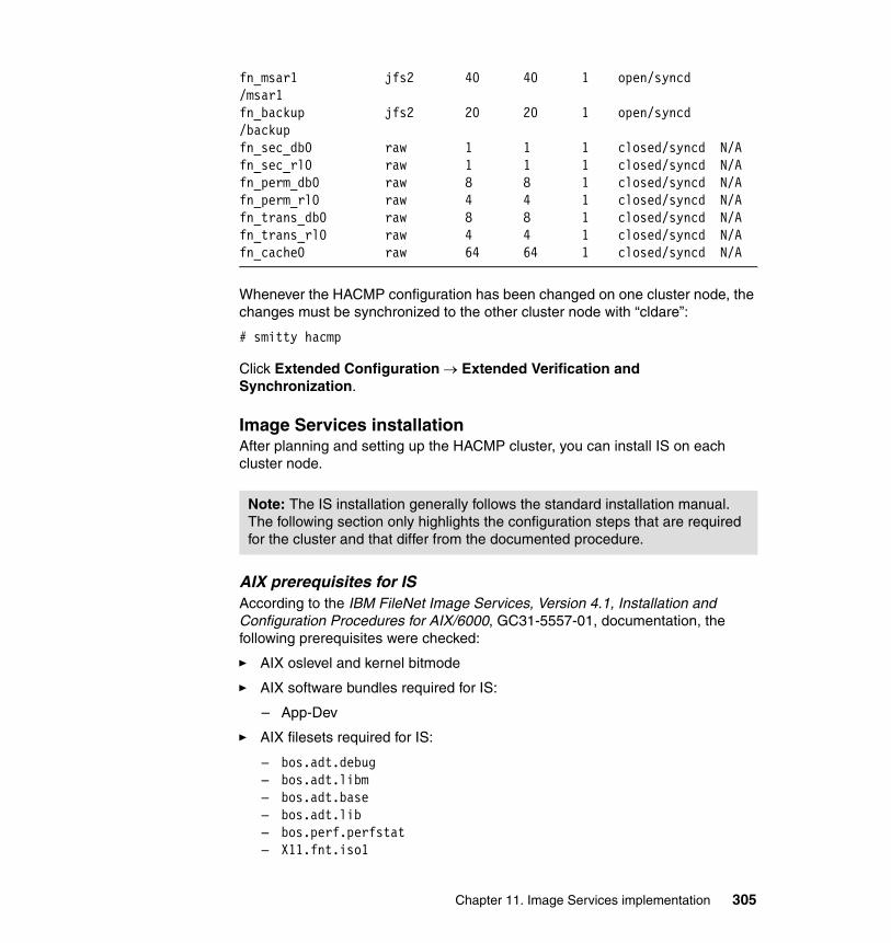
fn_msar1 jfs2 40 40 1 open/syncd /msar1fn_backup jfs2 20 20 1 open/syncd /backupfn_sec_db0 raw 1 1 1 closed/syncd N/Afn_sec_rl0 raw 1 1 1 closed/syncd N/Afn_perm_db0 raw 8 8 1 closed/syncd N/Afn_perm_rl0 raw 4 4 1 closed/syncd N/Afn_trans_db0 raw 8 8 1 closed/syncd N/Afn_trans_rl0 raw 4 4 1 closed/syncd N/Afn_cache0 raw 64 64 1 closed/syncd N/A
Whenever the HACMP configuration has been changed on one cluster node, the changes must be synchronized to the other cluster node with “cldare”:
# smitty hacmp
Click Extended Configuration → Extended Verification and Synchronization.
Image Services installationAfter planning and setting up the HACMP cluster, you can install IS on each cluster node.
AIX prerequisites for ISAccording to the IBM FileNet Image Services, Version 4.1, Installation and Configuration Procedures for AIX/6000, GC31-5557-01, documentation, the following prerequisites were checked:
� AIX oslevel and kernel bitmode
� AIX software bundles required for IS:
– App-Dev
� AIX filesets required for IS:
– bos.adt.debug– bos.adt.libm– bos.adt.base– bos.adt.lib– bos.perf.perfstat– X11.fnt.iso1
Note: The IS installation generally follows the standard installation manual. The following section only highlights the configuration steps that are required for the cluster and that differ from the documented procedure.
Chapter 11. Image Services implementation 305
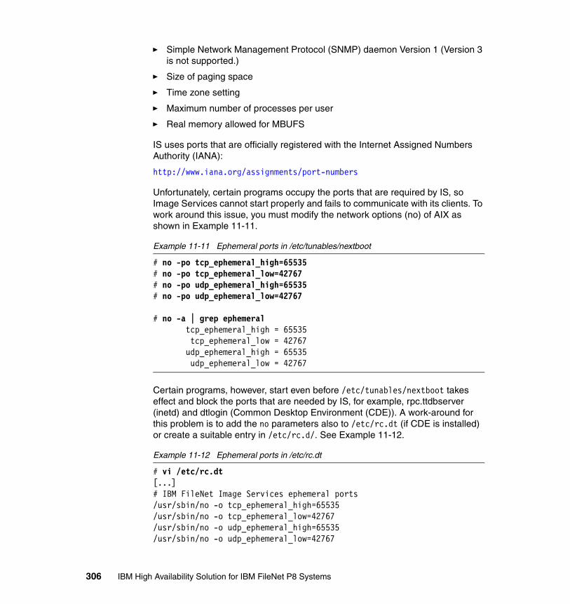
� Simple Network Management Protocol (SNMP) daemon Version 1 (Version 3 is not supported.)
� Size of paging space
� Time zone setting
� Maximum number of processes per user
� Real memory allowed for MBUFS
IS uses ports that are officially registered with the Internet Assigned Numbers Authority (IANA):
http://www.iana.org/assignments/port-numbers
Unfortunately, certain programs occupy the ports that are required by IS, so Image Services cannot start properly and fails to communicate with its clients. To work around this issue, you must modify the network options (no) of AIX as shown in Example 11-11.
Example 11-11 Ephemeral ports in /etc/tunables/nextboot
# no -po tcp_ephemeral_high=65535# no -po tcp_ephemeral_low=42767# no -po udp_ephemeral_high=65535# no -po udp_ephemeral_low=42767
# no -a | grep ephemeral tcp_ephemeral_high = 65535 tcp_ephemeral_low = 42767 udp_ephemeral_high = 65535 udp_ephemeral_low = 42767
Certain programs, however, start even before /etc/tunables/nextboot takes effect and block the ports that are needed by IS, for example, rpc.ttdbserver (inetd) and dtlogin (Common Desktop Environment (CDE)). A work-around for this problem is to add the no parameters also to /etc/rc.dt (if CDE is installed) or create a suitable entry in /etc/rc.d/. See Example 11-12.
Example 11-12 Ephemeral ports in /etc/rc.dt
# vi /etc/rc.dt[...]# IBM FileNet Image Services ephemeral ports/usr/sbin/no -o tcp_ephemeral_high=65535/usr/sbin/no -o tcp_ephemeral_low=42767/usr/sbin/no -o udp_ephemeral_high=65535/usr/sbin/no -o udp_ephemeral_low=42767
306 IBM High Availability Solution for IBM FileNet P8 Systems

# IBM FileNet Image Services End[...]
AIX honors the port reservations for IS and reflects the reserved names and ports in its /etc/services file. Unfortunately, IS installers sometimes fail if the entry reads filenet-tms instead of tms. Therefore, we advise you to comment out existing filenet-tms, filenet-rpc, and filenet-nch entries in /etc/services before the IS installation starts. See Example 11-13.
Example 11-13 The /etc/services file with ports added by the IS installer
# egrep "32768|32769|32770" /etc/services# filenet-tms 32768/tcp # Filenet TMS# filenet-tms 32768/udp # Filenet TMS# filenet-rpc 32769/tcp # Filenet RPC# filenet-rpc 32769/udp # Filenet RPC# filenet-nch 32770/tcp # Filenet NCH# filenet-nch 32770/udp # Filenet NCHtms 32768/tcpcor 32769/tcpnch 32770/udp
You can use the rmsock command to find a process that is using the IS port. See Example 11-14 for an example of a process blocking IS port 32768.
Example 11-14 Process blocking IS port 32768
# netstat -Aan | grep 3276 | grep tcpf100020003932b98 tcp4 0 0 *.32768 *.* LISTENf100020003940b98 tcp4 0 0 *.32769 *.* LISTEN
# rmsock f100020003932b98 tcpcbThe socket 0x3932808 is being held by proccess 827454 (rpc.ttdbserver).
Just before the IS installation, the NCH entry for IS domain FNIS:FileNet was added to /etc/hosts. This entry points to the (virtual) IS service address, which the HACMP Resource Group provides. By using the highly available service address for IS, the clients will connect to the correct (active) node of the cluster.
Example 11-15 NCH entry in /etc/hosts
# vi /etc/hosts[...]9.30.188.78 fnis.svl.ibm.com fnis fnis-filenet-nch-server
Chapter 11. Image Services implementation 307
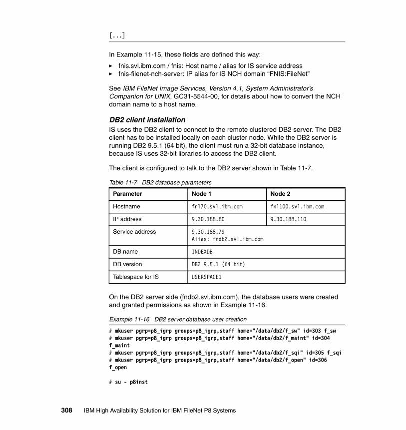
[...]
In Example 11-15, these fields are defined this way:
� fnis.svl.ibm.com / fnis: Host name / alias for IS service address� fnis-filenet-nch-server: IP alias for IS NCH domain “FNIS:FileNet”
See IBM FileNet Image Services, Version 4.1, System Administrator’s Companion for UNIX, GC31-5544-00, for details about how to convert the NCH domain name to a host name.
DB2 client installationIS uses the DB2 client to connect to the remote clustered DB2 server. The DB2 client has to be installed locally on each cluster node. While the DB2 server is running DB2 9.5.1 (64 bit), the client must run a 32-bit database instance, because IS uses 32-bit libraries to access the DB2 client.
The client is configured to talk to the DB2 server shown in Table 11-7.
Table 11-7 DB2 database parameters
On the DB2 server side (fndb2.svl.ibm.com), the database users were created and granted permissions as shown in Example 11-16.
Example 11-16 DB2 server database user creation
# mkuser pgrp=p8_igrp groups=p8_igrp,staff home="/data/db2/f_sw" id=303 f_sw# mkuser pgrp=p8_igrp groups=p8_igrp,staff home="/data/db2/f_maint" id=304 f_maint# mkuser pgrp=p8_igrp groups=p8_igrp,staff home="/data/db2/f_sqi" id=305 f_sqi# mkuser pgrp=p8_igrp groups=p8_igrp,staff home="/data/db2/f_open" id=306 f_open
# su - p8inst
Parameter Node 1 Node 2
Hostname fnl70.svl.ibm.com fnl100.svl.ibm.com
IP address 9.30.188.80 9.30.188.110
Service address 9.30.188.79Alias: fndb2.svl.ibm.com
DB name INDEXDB
DB version DB2 9.5.1 (64 bit)
Tablespace for IS USERSPACE1
308 IBM High Availability Solution for IBM FileNet P8 Systems

$ db2
db2 => grant createtab, bindadd, connect on database to user f_swDB20000I The SQL command completed successfully.db2 => grant createtab, bindadd, connect on database to user f_sqiDB20000I The SQL command completed successfully.db2 => grant createtab, bindadd, connect on database to user f_openDB20000I The SQL command completed successfully.db2 => grant dbadm on database to f_maintDB20000I The SQL command completed successfully.
db2 => quitDB20000I The QUIT command completed successfully.
$ db2set DB2_SNAPSHOT_NOAUTH=on
Example 11-17 shows the DB2 server configuration settings that are required to configure the DB2 client.
Example 11-17 DB2 server configuration
# su - p8inst$ db2 list node directory
Node Directory
Number of entries in the directory = 1
Node 1 entry:
Node name = DB2_B Comment = Directory entry type = LOCAL Protocol = TCPIP Hostname = fnl70 Service name = 50010
$ db2 list db directory
System Database Directory
Number of entries in the directory = 10[...]Database 8 entry:
Database alias = INDEXDB Database name = INDEXDB Local database directory = /data/db2/p8_inst Database release level = c.00 Comment = Directory entry type = Indirect
Chapter 11. Image Services implementation 309

Catalog database partition number = 0 Alternate server hostname = 9.30.188.80 Alternate server port number = 50010[...]
$ db2 connect to indexdb
Database Connection Information
Database server = DB2/AIX64 9.5.1 SQL authorization ID = P8INST Local database alias = INDEXDB
$ db2 list tablespaces
Tablespaces for Current Database
Tablespace ID = 0 Name = SYSCATSPACE Type = Database managed space Contents = All permanent data. Regular table space. State = 0x0000 Detailed explanation: Normal
Tablespace ID = 1 Name = TEMPSPACE1 Type = System managed space Contents = System Temporary data State = 0x0000 Detailed explanation: Normal
Tablespace ID = 2 Name = USERSPACE1 Type = Database managed space Contents = All permanent data. Large table space. State = 0x0000 Detailed explanation: Normal
Tablespace ID = 3 Name = SYSTOOLSPACE Type = Database managed space Contents = All permanent data. Large table space. State = 0x0000 Detailed explanation: Normal
Tablespace ID = 4 Name = SYSTOOLSTMPSPACE Type = System managed space Contents = User Temporary data State = 0x0000
310 IBM High Availability Solution for IBM FileNet P8 Systems
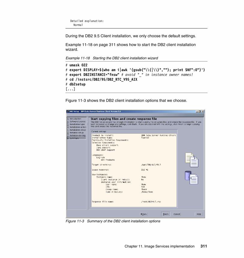
Detailed explanation: Normal
During the DB2 9.5 Client installation, we only choose the default settings.
Example 11-18 on page 311 shows how to start the DB2 client installation wizard.
Example 11-18 Starting the DB2 client installation wizard
# umask 022# export DISPLAY=$(who am i|awk '{gsub("\\(|\\)",""); print $NF":0"}')# export DB2INSTANCE="fnsw" # avoid "_" in instance owner names!# cd /instsrc/DB2/95/DB2_RTC_V95_AIX# db2setup[...]
Figure 11-3 shows the DB2 client installation options that we choose.
Figure 11-3 Summary of the DB2 client installation options
Chapter 11. Image Services implementation 311

After the installation completed, we configure the connection to the DB2 cluster server, and we create the local DB2 database catalog on each node. See Example 11-19.
Example 11-19 Creation of DB2 database catalog
# su - fnsw
$ db2 catalog tcpip node FNDB2 remote fndb2.svl.ibm.com server 50010DB20000I The CATALOG TCPIP NODE command completed successfully.DB21056W Directory changes may not be effective until the directory cache isrefreshed.
$ db2 catalog database INDEXDB as INDEXDB at node FNDB2DB20000I The CATALOG DATABASE command completed successfully.DB21056W Directory changes may not be effective until the directory cache isrefreshed.
$ db2 terminateDB20000I The TERMINATE command completed successfully.
$ db2 list node directory Node Directory
Number of entries in the directory = 1
Node 1 entry:
Node name = FNDB2 Comment = Directory entry type = LOCAL Protocol = TCPIP Hostname = fndb2.svl.ibm.com Service name = 50010
$ db2 list database directory System Database Directory
Number of entries in the directory = 1
Database 1 entry:
Database alias = INDEXDB Database name = INDEXDB Node name = FNDB2 Database release level = c.00 Comment = Directory entry type = Remote Catalog database partition number = -1 Alternate server hostname = 9.30.188.79 Alternate server port number = 50010
312 IBM High Availability Solution for IBM FileNet P8 Systems

Image Services installationImage Services normally requires three installations. For example:
� Image Services 4.1.0 General Availability (GA)� Image Services 4.1.0 Service Pack 2 (SP on top of GA) IS 4.1.2� Image Services 4.1.2 Fix Pack 3 (FP on top of SP) IS 4.1.2 FP 3
For this book, IS 4.1.2 (4.1.2.18, no FP) was installed using the SP installation wizard only. This Service Pack installs IS even without an existing GA installation. A Fix Pack was not available for this release.
In Example 11-20, we use the SP installation wizard to install IS 4.1.2.
Example 11-20 Installing IS 4.1.2
# mount -t fnvg # make sure the target file systems are mounted# mount | grep fnsw /dev/fn_fnsw /fnsw jfs2 Sep 24 10:04 rw,log=/dev/hd8 /dev/fn_local /fnsw/local jfs2 Sep 25 11:26 rw,log=/dev/fnvg_jfs2log
# export DISPLAY=$(who am i|awk '{gsub("\\(|\\)",""); print $NF":0"}')# cd /instsrc/IM/IS412-18# is_4.1.2_aix.bin
InstallShield WizardInitializing InstallShield Wizard...Preparing Java(tm) Virtual Machine...Running InstallShield Wizard...
Figure 11-4 shows the installation summary of IS on our lab system.
Chapter 11. Image Services implementation 313
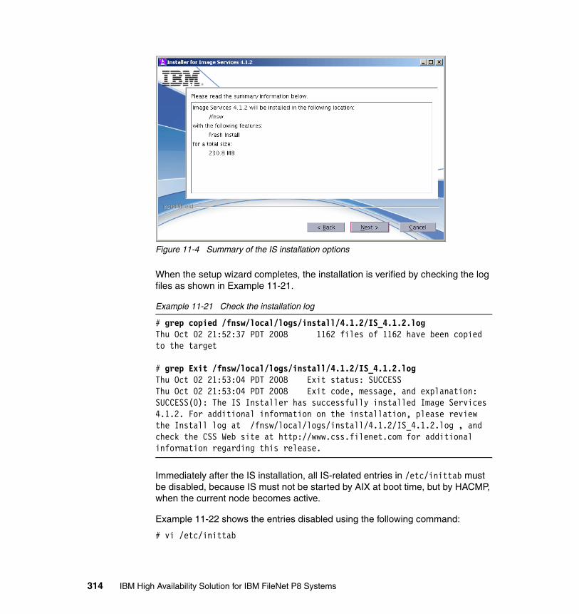
Figure 11-4 Summary of the IS installation options
When the setup wizard completes, the installation is verified by checking the log files as shown in Example 11-21.
Example 11-21 Check the installation log
# grep copied /fnsw/local/logs/install/4.1.2/IS_4.1.2.logThu Oct 02 21:52:37 PDT 2008 1162 files of 1162 have been copied to the target
# grep Exit /fnsw/local/logs/install/4.1.2/IS_4.1.2.logThu Oct 02 21:53:04 PDT 2008 Exit status: SUCCESSThu Oct 02 21:53:04 PDT 2008 Exit code, message, and explanation: SUCCESS(0): The IS Installer has successfully installed Image Services 4.1.2. For additional information on the installation, please review the Install log at /fnsw/local/logs/install/4.1.2/IS_4.1.2.log , and check the CSS Web site at http://www.css.filenet.com for additional information regarding this release.
Immediately after the IS installation, all IS-related entries in /etc/inittab must be disabled, because IS must not be started by AIX at boot time, but by HACMP, when the current node becomes active.
Example 11-22 shows the entries disabled using the following command:
# vi /etc/inittab
314 IBM High Availability Solution for IBM FileNet P8 Systems
Example 11-22 Disabled IS entries in /etc/inittab
:: IBM FileNet Image Services disabled for HACMP:: rcfn:234:wait:/bin/sh /etc/rc.initfnsw </dev/console >/dev/console 2>&1:: rcfnext:2:once:/etc/rc.fnext 2>&1 | alog -tboot >/dev/console 2>&1:: rcfnodd:2:wait:/etc/rc.fnodd 2>&1 | alog -tboot >/dev/console 2>&1:: rcsingle:1:wait:/etc/rc.single 2>&1 | alog -tboot >/dev/console 2>&1:: dupip:2:wait:/fnsw/etc/dupip:: IBM FileNet Image Services End
The profile of the fnsw user (and optionally also of the root user) must be updated to include the environment variable required for IS as shown in Example 11-23.
Example 11-23 Modification of fnsw’s .profile for IS
# su - fnsw# /fnsw/etc/inst_templates
# . ~/.profile # or “exit” and “login” to activate .profile
# env | grep DB2DB2_HOME=/home/fnsw/sqllibDB2INSTANCE=fnswDB2_INST=fnsw
The profiles of fnsw ($HOME/.*) must match on all cluster nodes to make sure that IS starts with the same environment.
Image Services configurationThe first step to configure IS is to run fn_setup as fnsw user as shown in Example 11-24. There is no cluster-related parameter in this part of the configuration.
Example 11-24 IS configuration with fn_setup
# su - fnsw# export DISPLAY=$(who am i|awk '{gsub("\\(|\\)",""); print $NF":0"}')
# fn_setup
Note: The best way to disable inittab entries is by adding a colon (:) in front of the line, or by changing the action to “off” instead of “once” or “wait”.
The IS installer creates an entry rcfn with # as a first character, but this action will not comment out the line. This entry must also be disabled by adding a colon (:).
Chapter 11. Image Services implementation 315

Is this the NCH server (1=yes, 2=no) [1]:Enter NCH server name []: FNIS:FileNetEnter system serial number [0]: 110012345Enter the relational database type configured on this server (0=None, 1=Oracle, 2=DB2) [0]: 2Enter the relational database home directory [/home/fnsw/sqllib]: This is the setup configuration: NCH server name: FNIS:FileNet SSN: 110012345 Relational database type: db2 Relational database home: /home/fnsw/sqllibDo you want to continue (y/n) [y]: yfn_setup: Creating file /fnsw/local/setup_configfn_setup: Creating file /fnsw/local/sd/root_stationfn_setup: Creating file /fnsw/local/ssnfn_setup: Creating file /fnsw/local/sd/nch_domainfn_setup: Changing permission on FileNET IS software and databasesfn_setup: Creating file /fnsw/local/sd/NCH_db0fn_setup: Running "/fnsw/bin/fn_util initnch"fn_util: creating NCH database.fn_setup: Running "/fnsw/bin/nch_update FNIS:FileNet"fn_setup: Installing Image Services license.Successfully installed license data !fn_setup: Changing permission on FileNET IS software and databases
The fn_setup program also installs the Universal SLAC Key (license code) into the IS NCH database. Because this key works on any server, there is no longer a dedicated “HA/DR” license key required for IS to run on separate hosts.
If the system had an optical storage library (OSAR) connected, the fnsod.install script must be run on AIX and Solaris servers after all IS service packs (SPs) and fix packs (FPs) have been applied:
# /fnsw/bin/fnsod.install
The IS Configuration Editor (fn_edit) has to be used on node 1 of the cluster only, because its configuration files (/fnsw/local/sd/conf_db/IMS_*.cdb) are located on the shared disks and will be switched over to the standby node by HACMP. Example 11-25 shows the IS configuration with fn_edit.
Example 11-25 IS configuration with fn_edit
# su - fnsw$ export DISPLAY=$(who am i|awk '{gsub("\\(|\\)",""); print $NF":0"}')
$ fn_edit
$ fn_build -a
316 IBM High Availability Solution for IBM FileNet P8 Systems

The only cluster-related entry in fn_edit really is the IP address in the Network Addresses tab (see Figure 11-5).
Figure 11-5 HACMP service address that is used for IS
IS requires links in /fnsw/dev/1 that point to shared logical volumes in /dev, which will be used as raw devices for Multi-Keyed File (MKF) databases and document cache. See Table 11-8 on page 317.
The links might be realized as soft links (ln -s) or through the character device file using the major and minor number of the raw device (mknod). The soft links are the preferred way to link to the raw devices and need to be created with the fn_util mk_links command.
The links to OSAR A (osara) and OSAR A drive 1 and 2 (odda*) only exist when an OSAR is attached to the system, and fnsod.install has been run previously.
Table 11-8 Local links from /fnsw/dev/1 to shared raw devices
Local link Shared LV/Device Use
/fnsw/dev/1/sec_db0 /dev/rfn_sec_db0 Security database
/fnsw/dev/1/sec_rl0 /dev/rfn_sec_rl0 Security redo log
/fnsw/dev/1/permanent_db0 /dev/rfn_perm_db0 Permanent database
/fnsw/dev/1/permanent_rl0 /dev/rfn_perm_rl0 Permanent redo log
/fnsw/dev/1/transient_db0 /dev/rfn_trans_db0 Transient database
/fnsw/dev/1/transient_rl0 /dev/rfn_trans_rl0 Transient redo log
/fnsw/dev/1/cache0 /dev/rfn_cache0 Document cache
/fnsw/dev/1/osara /dev/fnsod.5,0,4,0 OSAR “A” Robotic Arm
/fnsw/dev/1/odda1 /dev/fnsod.5,0,3,0 OSAR “A” Drive 1
/fnsw/dev/1/odda2 /dev/fnsod.5,0,2,0 OSAR “A” Drive 2
Chapter 11. Image Services implementation 317

The links to the databases and OSAR drivers in /fnsw/dev/1 are created locally with fn_util mk_links and also have to be created on the standby node later, because this directory is located on the local disks (in /fnsw). See Example 11-26.
Example 11-26 Creation of links in /fnsw/dev/1
# su - fnsw$ fn_util mk_linksfn_util: done
$ ls -l /fnsw/dev/1total 0lrwxrwxrwx 1 fnsw fnusr 15 Oct 02 22:18 cache0@ -> /dev/rfn_cache0lrwxrwxrwx 1 fnsw fnusr 17 Oct 02 22:18 permanent_db0@ -> /dev/rfn_perm_db0lrwxrwxrwx 1 fnsw fnusr 17 Oct 02 22:18 permanent_rl0@ -> /dev/rfn_perm_rl0lrwxrwxrwx 1 fnsw fnusr 16 Oct 02 22:18 sec_db0@ -> /dev/rfn_sec_db0lrwxrwxrwx 1 fnsw fnusr 16 Oct 02 22:18 sec_rl0@ -> /dev/rfn_sec_rl0lrwxrwxrwx 1 fnsw fnusr 18 Oct 02 22:18 transient_db0@ -> /dev/rfn_trans_db0lrwxrwxrwx 1 fnsw fnusr 18 Oct 02 22:18 transient_rl0@ -> /dev/rfn_trans_rl0
The link to the DB2 client is also local to rootvg and has to be created on the standby node, as well. See Example 11-27.
Example 11-27 Creating link to DB2 client
# su - fnsw$ fn_util linkrdbfn_util: done
$ ls -l /fnsw/lib/shobj/db2liblrwxrwxrwx 1 fnsw fnusr 23 Oct 02 22:19 /fnsw/lib/shobj/db2lib@ -> /home/fnsw/sqllib/lib32/
After configuring the DB2 passwords, the database has to be initialized, which creates the IS tables. This task must only be done one time from node 1 of the cluster. See Example 11-28.
Example 11-28 Initialization of the DB2 database
# su - fnsw$ fn_setup_rdb -f # make DB passwords known to IS----------------------------------------------------------------fn_setup_rdb - Install version----------------------------------------------------------------Upgrade IS. Running fn_migrate ...
318 IBM High Availability Solution for IBM FileNet P8 Systems
Running fn_build -aRDBMS type: DB2Please enter the f_maint user password (note: password will not echo):Please enter the f_maint user password again for verification:Please enter the f_sw user password (note: password will not echo):Please enter the f_sw user password again for verification:Please enter the f_sqi user password (note: password will not echo):Please enter the f_sqi user password again for verification:Please enter the f_open user password (note: password will not echo):Please enter the f_open user password again for verification:fn_util: Special RDB password file is createdfn_util: doneSuccessfully verifying logons for the above users.Execution complete.
# fn_util init # This will create or replace (DELETE) existing objects![...]
If the system requires an adapted configuration for the Pooled Process Manager (PPM), you must modify /fnsw/etc/serverConfig now. This configuration file is also located on the local disks of node 1 and must be copied over to node 2 later:
# vi /fnsw/etc/serverConfig
IS Toolkit installationWe install the IS Toolkit (ISTK) 4.1.2 locally on each IS cluster node, because it might be useful for creating a customer-specific application monitor. The ISTK is optional, but it might also be required for applications, such as DART, HPII, MRII, BatchIt, and for customer-created applications that act as a client for IS. See Example 11-29.
Example 11-29 Installation of the IS Toolkit
# export DISPLAY=$(who am i|awk '{gsub("\\(|\\)",""); print $NF":0"}')# cd /instsrc/IM/ISTK412-18/# ./istk_4.1.2_aix.bin
InstallShield WizardInitializing InstallShield Wizard...Preparing Java(tm) Virtual Machine...Running InstallShield Wizard...
# more /fnsw/client/logs/install/4_1_2/install_ISTK_Runtime_log.txt
# rm -r /fnsw/client_backup
If you install and use ISTK, start and stop it with the IS application server scripts.
Chapter 11. Image Services implementation 319

Because ISTK is installed locally (in /fnsw/client), it does not interfere with the IS takeover. However, because it is a client to IS, it will be affected by the takeover and must be restarted with IS.
ISTK applications and IS are often started on the same node (by the IS start script), because usually when IS needs to fail over to the standby node, there is a problem, and ISTK also might not work properly any longer. Then again, ISTK might be started on the “inactive” node to create a form of load balancing and an active (IS)/active (ISTK) cluster. This approach works only if each node has a local copy of the /fnsw file system.
CFS-IS configurationWe configure Content Federation Services for IS (CFS-IS), so that the Content Engine (CE) of the P8 system can use IS as a repository and IS can federate new documents to CE.
The CFS-IS documentation, IBM FileNet P8 Content Federation Services for Image Services, Version 4.0, Guidelines, GC31-5484, states that “IS systems with remote clustered databases are not supported.” This statement is out-of-date and no longer true with IS 4.1.2, as shown in this book.
We create the following configuration in Xapex for CFS-IS:
� Security:
– User: CFSADMIN– Group: CFSRMGRP– Max. Logons: 100
� Media family:
– Tranlog 1: CFSTEST_T_M_8G (Tranlog) — MSAR a (/msar1)– Primary: CFSTEST_P_M_8G (Primary) — MSAR a (/msar1)
� Document class
– Class Name: Contracts
� Indexes
– LastName: IS: String (25), key — CE: String (26)– FirstName: IS: String (25) — CE: String (26)– SSN: IS: String (11), key — CE: String (12)– Income: IS: Numeric — CE: Float– Approver: IS: String (25), key — CE: String (26)– Approval: IS: String (2), key — CE: String (3)
One of the first steps of the CFS-IS configuration is to run the IS Record Management (RM) utility, as shown in Example 11-30.
320 IBM High Availability Solution for IBM FileNet P8 Systems
Example 11-30 CFS-IS RM configuration
# su - fnsw# SEC_rm_config
Image Services Record Management Configuration Utility
Command line options:
d Display current configuration settings e Edit configuration settings s Save configuration settings p Print Menu q Quit
Enter command => d
Current Image Services Configuration:Record Security Level : READ_ONLYRM Group : UNDEFINEDRM Log Level : MINIMAL
Current User Selected Configuration:Record Security Level : READ_ONLYRM Group : UNDEFINEDRM Log Level : MINIMAL
Enter command => e
Edit Record Level Security
s READ_ONLYw APPEND_ONLYn NO_CHANGEEnter Record Level Security [READ_ONLY] => n
Edit Record Manager Group
Enter Record Manager Group Name [UNDEFINED] => CFSRMGRP
Edit Activity Log Level
m MINIMALv VERBOSEEnter Activity Log Level [MINIMAL] => m
Enter command => s
Saving Record Management control table information...SEC_rm_config: Record Management settings have been successfully updated
Enter command => d
Current Image Services Configuration:
Chapter 11. Image Services implementation 321

Record Security Level : NO_CHANGERM Group : CFSRMGRPRM Log Level : MINIMAL
Current User Selected Configuration:Record Security Level : NO_CHANGERM Group : CFSRMGRPRM Log Level : MINIMAL
Enter command => q
Exiting...
On the Content Engine (CE), we add the NCH entry fnis-filenet-nch-server to C:\WINDOWS\system32\drivers\etc\hosts on both CE servers.
In Enterprise Manager (EM) on the CE, we create the document class Contracts as a sub-class of FNIS (IS system), which is again a sub-class of the Image Services parent document class by using Image Services → FNIS → Contracts.
After we configure CFS-IS on both IS and CE, we start the CFS Agents for Import and Export of documents (in EM on the CE).
The CFS-IS error log is located on each of the CE servers:
# cd /usr/IBM/WebSphere/AppServer/profiles/server1/FileNet/server1/# pg p8_server_error.log
For troubleshooting, CFS-IS tracing can be (temporarily) enabled in EM for the whole system, click Enterprise Manager [FNHA] → Properties → Trace Control.
You can also enable tracing individually for each server (for example, server1) by clicking Enterprise Manager [FNHA] → Sites → Initial Site [Default] → Virtual Servers → fnl10Node01 → server1 → Properties → Trace Control.
Enable tracing for the CFS Daemon and the CFS Import Agent.
The trace log that is created on the CE server is p8_server_trace.log:
# cd /usr/IBM/WebSphere/AppServer/profiles/server1/FileNet/server1/# pg p8_server_trace.log
CFS-IS was tested as part of the IS takeover tests and did not show a problem when IS was restarted due to the takeover.
322 IBM High Availability Solution for IBM FileNet P8 Systems
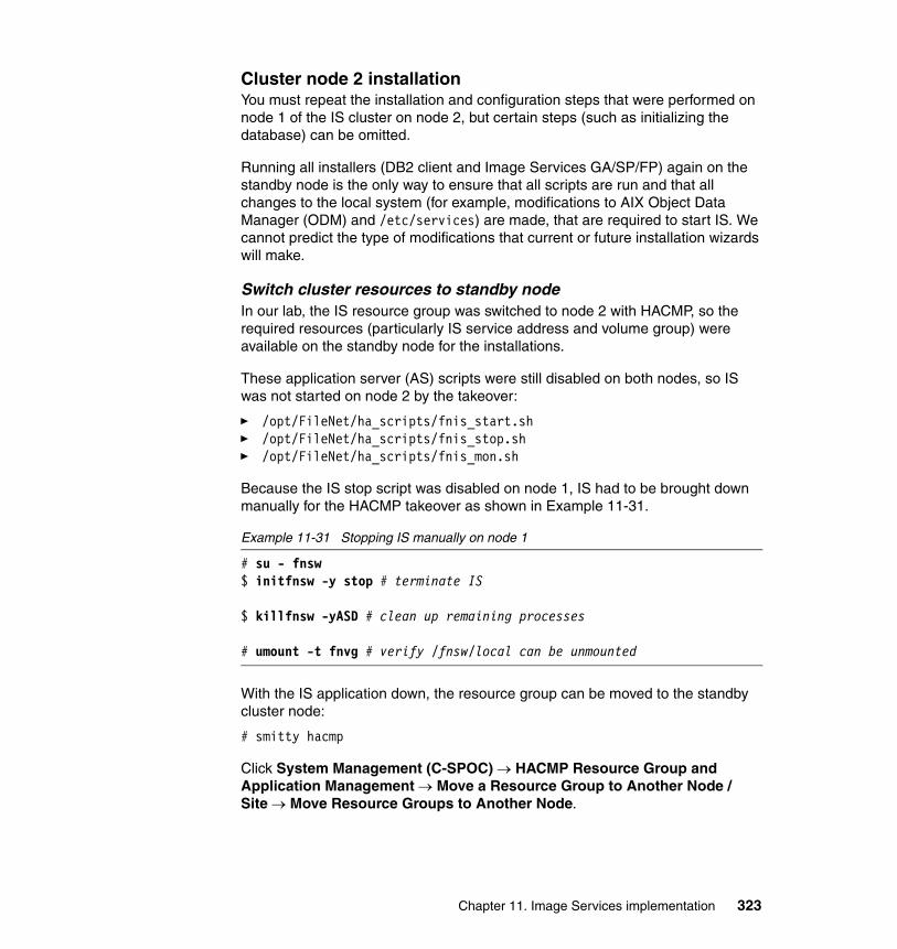
Cluster node 2 installationYou must repeat the installation and configuration steps that were performed on node 1 of the IS cluster on node 2, but certain steps (such as initializing the database) can be omitted.
Running all installers (DB2 client and Image Services GA/SP/FP) again on the standby node is the only way to ensure that all scripts are run and that all changes to the local system (for example, modifications to AIX Object Data Manager (ODM) and /etc/services) are made, that are required to start IS. We cannot predict the type of modifications that current or future installation wizards will make.
Switch cluster resources to standby nodeIn our lab, the IS resource group was switched to node 2 with HACMP, so the required resources (particularly IS service address and volume group) were available on the standby node for the installations.
These application server (AS) scripts were still disabled on both nodes, so IS was not started on node 2 by the takeover:
� /opt/FileNet/ha_scripts/fnis_start.sh� /opt/FileNet/ha_scripts/fnis_stop.sh� /opt/FileNet/ha_scripts/fnis_mon.sh
Because the IS stop script was disabled on node 1, IS had to be brought down manually for the HACMP takeover as shown in Example 11-31.
Example 11-31 Stopping IS manually on node 1
# su - fnsw$ initfnsw -y stop # terminate IS
$ killfnsw -yASD # clean up remaining processes
# umount -t fnvg # verify /fnsw/local can be unmounted
With the IS application down, the resource group can be moved to the standby cluster node:
# smitty hacmp
Click System Management (C-SPOC) → HACMP Resource Group and Application Management → Move a Resource Group to Another Node / Site → Move Resource Groups to Another Node.
Chapter 11. Image Services implementation 323
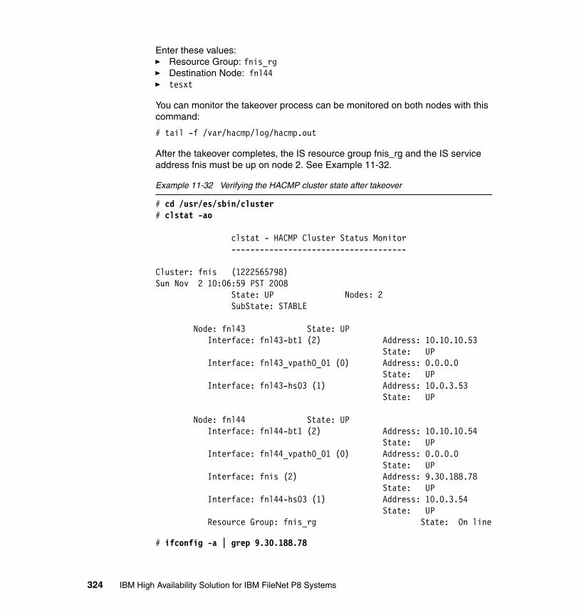
Enter these values:� Resource Group: fnis_rg� Destination Node: fnl44� tesxt
You can monitor the takeover process can be monitored on both nodes with this command:
# tail -f /var/hacmp/log/hacmp.out
After the takeover completes, the IS resource group fnis_rg and the IS service address fnis must be up on node 2. See Example 11-32.
Example 11-32 Verifying the HACMP cluster state after takeover
# cd /usr/es/sbin/cluster# clstat -ao
clstat - HACMP Cluster Status Monitor -------------------------------------
Cluster: fnis (1222565798)Sun Nov 2 10:06:59 PST 2008 State: UP Nodes: 2 SubState: STABLE
Node: fnl43 State: UP Interface: fnl43-bt1 (2) Address: 10.10.10.53 State: UP Interface: fnl43_vpath0_01 (0) Address: 0.0.0.0 State: UP Interface: fnl43-hs03 (1) Address: 10.0.3.53 State: UP
Node: fnl44 State: UP Interface: fnl44-bt1 (2) Address: 10.10.10.54 State: UP Interface: fnl44_vpath0_01 (0) Address: 0.0.0.0 State: UP Interface: fnis (2) Address: 9.30.188.78 State: UP Interface: fnl44-hs03 (1) Address: 10.0.3.54 State: UP Resource Group: fnis_rg State: On line
# ifconfig -a | grep 9.30.188.78
324 IBM High Availability Solution for IBM FileNet P8 Systems

inet 9.30.188.78 netmask 0xffffff00 broadcast 9.30.188.255
# mount | grep fnvg /dev/fn_local /fnsw/local jfs2 Nov 02 09:03 rw,log=/dev/fnvg_jfs2log /dev/fn_msar1 /msar1 jfs2 Nov 02 09:03 rw,log=/dev/fnvg_jfs2log /dev/fn_backup /backup jfs2 Nov 02 09:03 rw,log=/dev/fnvg_jfs2log
Installation steps on node 2When the IS service address and fnvg volume group are available on node 2, you must repeat all of the installation steps from node 1 on the standby node.
With the following exceptions, you must repeat all of the steps in “Image Services installation” on page 305:
� You must make a backup of the latest IS Configuration Database (CDB) in /fnsw/local/sd/conf_db in advance.
� DB2 server users already exist and are not required to be created again.
� You are not required to run the IS Configuration Editor (fn_edit) again. If the latest CDB file is missing, restore it from the previous backup. You do have to run the steps following fn_build again.
� You must not initialize the databases another time with fn_util init.
The /fnsw/etc/serverConfig file was created locally on node 1 during the initial installations. It might be copied over from node 1 to node 2 so that it does not have to be created another time.
The following files from node 1 might be copied partially or with extreme care to node 2. Use the IS-related entries only:
� /etc/hosts� /etc/inittab� /etc/tunables/nextboot� /etc/rc.dt
IS cluster scripts for HACMPIS is integrated into the HACMP resource group (RG) fnis_rg by means of the application server (AS) fnis_app_srv. The AS uses the following start, stop, and monitor scripts to control the IS application:
� /opt/FileNet/ha_scripts/fnis_start.sh # Start script� /opt/FileNet/ha_scripts/fnis_stop.sh # Stop script� /opt/FileNet/ha_scripts/fnis_mon.sh # Monitor script
Chapter 11. Image Services implementation 325
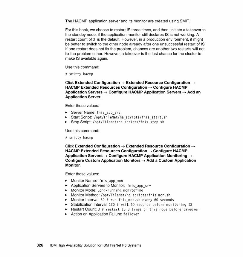
The HACMP application server and its monitor are created using SMIT.
For this book, we choose to restart IS three times, and then, initiate a takeover to the standby node, if the application monitor still declares IS is not working. A restart count of 3 is the default. However, in a production environment, it might be better to switch to the other node already after one unsuccessful restart of IS. If one restart does not fix the problem, chances are another two restarts will not fix the problem either. However, a takeover is the last chance for the cluster to make IS available again.
Use this command:
# smitty hacmp
Click Extended Configuration → Extended Resource Configuration → HACMP Extended Resources Configuration → Configure HACMP Application Servers → Configure HACMP Application Servers → Add an Application Server.
Enter these values:
� Server Name: fnis_app_srv� Start Script: /opt/FileNet/ha_scripts/fnis_start.sh� Stop Script: /opt/FileNet/ha_scripts/fnis_stop.sh
Use this command:
# smitty hacmp
Click Extended Configuration → Extended Resource Configuration → HACMP Extended Resources Configuration → Configure HACMP Application Servers → Configure HACMP Application Monitoring → Configure Custom Application Monitors → Add a Custom Application Monitor.
Enter these values:
� Monitor Name: fnis_app_mon� Application Servers to Monitor: fnis_app_srv� Monitor Mode: Long-running monitoring� Monitor Method: /opt/FileNet/ha_scripts/fnis_mon.sh� Monitor Interval: 60 # run fnis_mon.sh every 60 seconds� Stabilization Interval: 120 # wait 60 seconds before monitoring IS� Restart Count: 3 # restart IS 3 times on this node before takeover� Action on Application Failure: fallover
326 IBM High Availability Solution for IBM FileNet P8 Systems
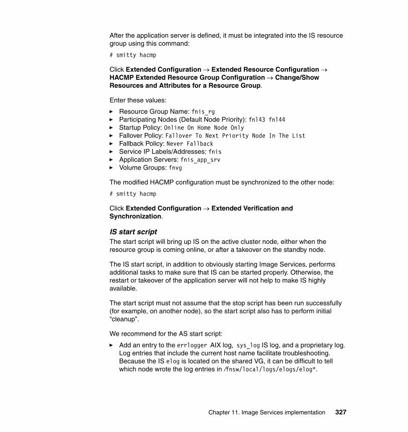
After the application server is defined, it must be integrated into the IS resource group using this command:
# smitty hacmp
Click Extended Configuration → Extended Resource Configuration → HACMP Extended Resource Group Configuration → Change/Show Resources and Attributes for a Resource Group.
Enter these values:
� Resource Group Name: fnis_rg� Participating Nodes (Default Node Priority): fnl43 fnl44� Startup Policy: Online On Home Node Only� Fallover Policy: Fallover To Next Priority Node In The List� Fallback Policy: Never Fallback� Service IP Labels/Addresses: fnis� Application Servers: fnis_app_srv� Volume Groups: fnvg
The modified HACMP configuration must be synchronized to the other node:
# smitty hacmp
Click Extended Configuration → Extended Verification and Synchronization.
IS start scriptThe start script will bring up IS on the active cluster node, either when the resource group is coming online, or after a takeover on the standby node.
The IS start script, in addition to obviously starting Image Services, performs additional tasks to make sure that IS can be started properly. Otherwise, the restart or takeover of the application server will not help to make IS highly available.
The start script must not assume that the stop script has been run successfully (for example, on another node), so the start script also has to perform initial “cleanup”.
We recommend for the AS start script:
� Add an entry to the errlogger AIX log, sys_log IS log, and a proprietary log. Log entries that include the current host name facilitate troubleshooting. Because the IS elog is located on the shared VG, it can be difficult to tell which node wrote the log entries in /fnsw/local/logs/elogs/elog*.
Chapter 11. Image Services implementation 327
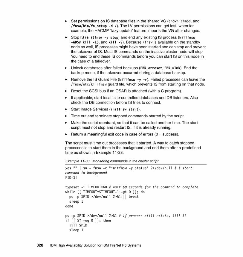
� Set permissions on IS database files in the shared VG (chown, chmod, and /fnsw/bin/fn_setup -d /). The LV permissions can get lost, when for example, the HACMP “lazy update” feature imports the VG after changes.
� Stop IS (initfnsw -y stop) and end any existing IS process (killfnsw -ADSy, kill -15, and kill -9). Because /fnsw is available on the standby node as well, IS processes might have been started and can stop and prevent the takeover of IS. Most IS commands on the inactive cluster node will stop. You need to end these IS commands before you can start IS on this node in the case of a takeover.
� Unlock databases after failed backups (EBR_orreset, EBR_ulmk). End the backup mode, if the takeover occurred during a database backup.
� Remove the IS Guard File (killfnsw -y -r). Failed processes can leave the /fnsw/etc/killfnsw guard file, which prevents IS from starting on that node.
� Reset the SCSI bus if an OSAR is attached (with a C program).
� If applicable, start local, site-controlled databases and DB listeners. Also check the DB connection before IS tries to connect.
� Start Image Services (initfnsw start).
� Time out and terminate stopped commands started by the script.
� Make the script reentrant, so that it can be called another time. The start script must not stop and restart IS, if it is already running.
� Return a meaningful exit code in case of errors (0 = success).
The script must time out processes that it started. A way to catch stopped processes is to start them in the background and end them after a predefined time as shown in Example 11-33.
Example 11-33 Monitoring commands in the cluster script
yes "" | su - fnsw -c "initfnsw -y status" 2>/dev/null & # start command in backgroundPID=$!
typeset -i TIMEOUT=60 # wait 60 seconds for the command to completewhile [[ TIMEOUT=$TIMEOUT-1 -gt 0 ]]; do ps -p $PID >/dev/null 2>&1 || break sleep 1done
ps -p $PID >/dev/null 2>&1 # if process still exists, kill itif [[ $? -eq 0 ]]; then kill $PID sleep 3
328 IBM High Availability Solution for IBM FileNet P8 Systems
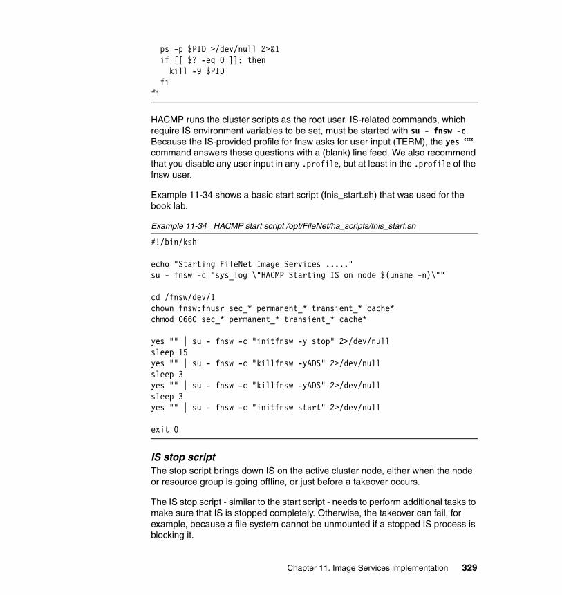
ps -p $PID >/dev/null 2>&1 if [[ $? -eq 0 ]]; then kill -9 $PID fifi
HACMP runs the cluster scripts as the root user. IS-related commands, which require IS environment variables to be set, must be started with su - fnsw -c. Because the IS-provided profile for fnsw asks for user input (TERM), the yes ““ command answers these questions with a (blank) line feed. We also recommend that you disable any user input in any .profile, but at least in the .profile of the fnsw user.
Example 11-34 shows a basic start script (fnis_start.sh) that was used for the book lab.
Example 11-34 HACMP start script /opt/FileNet/ha_scripts/fnis_start.sh
#!/bin/ksh
echo "Starting FileNet Image Services ....."su - fnsw -c "sys_log \"HACMP Starting IS on node $(uname -n)\""
cd /fnsw/dev/1chown fnsw:fnusr sec_* permanent_* transient_* cache*chmod 0660 sec_* permanent_* transient_* cache*
yes "" | su - fnsw -c "initfnsw -y stop" 2>/dev/nullsleep 15yes "" | su - fnsw -c "killfnsw -yADS" 2>/dev/nullsleep 3yes "" | su - fnsw -c "killfnsw -yADS" 2>/dev/nullsleep 3yes "" | su - fnsw -c "initfnsw start" 2>/dev/null
exit 0
IS stop scriptThe stop script brings down IS on the active cluster node, either when the node or resource group is going offline, or just before a takeover occurs.
The IS stop script - similar to the start script - needs to perform additional tasks to make sure that IS is stopped completely. Otherwise, the takeover can fail, for example, because a file system cannot be unmounted if a stopped IS process is blocking it.
Chapter 11. Image Services implementation 329

We recommend for the AS stop script:
� Add an entry to the errlogger AIX log, sys_log IS log, and a proprietary log.
� Remove the IS Guard File (killfnsw -y -r).
� Stop Image Services (initfnsw -y stop).
� End any remaining IS process (killfnsw -ADSy, kill -15, and kill -9). The files in /fnsw/procs might also help to find remaining IS processes.
� If applicable, end any IS client process, for example, ISTK clients (/fnsw/client/bin/wal_purge), COLD (/fnsw/bin/cold_3770), or DART/HPII/MRII.
� End any process owned by fnsw or fnusr or any ISTK user, plus all vl -t processes (kill -15 or kill -9). With X/CDE, aixterm -e might run vl -t processes that can easily be missed and have to be ended separately.
� If applicable, stop local, site-controlled databases and DB listeners.
� End any process accessing and blocking a shared file system (fuser -ku /dev/fn_fnsw). Remember to use the LV device for fuser, not the file system, to catch processes in all subdirectories of the FS, as well.
� Remove the shared memory that owned by fnsw or fnusr (ipcs and ipcrm).
� Unload unused shared libraries (slibclean).
� Time out and terminate stopped commands that were started by the script.
� Make the script reentrant, so that it can handle being called another time. The stop script might try to stop IS again (as a “clean” script), even if IS is already stopped.
� Return a meaningful exit code in case of errors (0 = success).
We recommend that you add code for troubleshooting to the stop script (such as calling /fnsw/bin/ipc_tool or /fnsw/support/911) to collect data that will be lost when IS is terminated, but to disable this code for normal cluster operation. In the case of a failure, a reliable restart or takeover of IS is usually more important than collecting debug information.
Example 11-35 shows a basic stop script called fnis_stop.sh that was used for the book lab.
Example 11-35 HACMP stop script /opt/FileNet/ha_scripts/fnis_stop.sh
#!/bin/ksh
echo "Stopping FileNet Image Services ....."
# Try to stop IS gracefully
330 IBM High Availability Solution for IBM FileNet P8 Systems

yes "" | su - fnsw -c "sys_log \"HACMP Stopping IS on node $(uname -n)\"" 2>/dev/null
# Terminate remaining IS processesyes "" | su - fnsw -c "initfnsw -y stop" 2>/dev/nullsleep 15yes "" | su - fnsw -c "killfnsw -yADS" 2>/dev/nullsleep 3yes "" | su - fnsw -c "killfnsw -yADS" 2>/dev/null
# Kill all processes of user fnsw or group fnusrfor PID in $(ps -ef | awk '$1=="fnsw" {print $2}'); do echo "Killing process $PID ($(ps -p $PID -o comm | tail -1)) ..." kill $PID sleep 3 ps -p $PID >/dev/null 2>&1 if [[ $? -eq 0 ]]; then kill -9 $PID fidone
# Clean up shared memoryipcs -s | awk '$5=="fnsw"||$6=="fnusr" {system("ipcrm -s "$2)}'ipcs -q | awk '$5=="fnsw"||$6=="fnusr" {system("ipcrm -q "$2)}'ipcs -m | awk '$5=="fnsw"||$6=="fnusr" {system("ipcrm -m "$2)}'
slibclean
exit 0
IS monitor scriptThe IS monitor script tells HACMP if the application server is still working, or if a restart or takeover of the IS resource group is required.
Monitoring Image Services can be extremely tricky, because IS has many processes that are configurable in number, or start on demand only. A running process does not guarantee IS is still working properly and can be accessed by clients. The TM_daemon process, for example, rarely ends when IS stops. Therefore, we recommend that you use an HACMP Custom Application Monitor (a monitor shell script) instead of a Process Application Monitor. A Process Application Monitor is not flexible enough to handle changing numbers of processes and also cannot “talk” to IS to see if it is actually working.
Chapter 11. Image Services implementation 331

The IS monitor script needs to cover all of the components of the IS server, such as network, databases, security, and document retrieval. Here are suggestions for what the monitor can cover, even though several suggestions might not apply in all IS configurations:
� Add an entry to the errlogger AIX log, sys_log IS log, and a proprietary log if a failure is detected.
� Verify that IS core processes are running, for example, TM_daemon, COR_Listen, NCH_daemon, bes_commit, or ds_init. 0 to n instances of a process might be running, depending on the configuration of IS. A sophisticated monitor can check the CDB for the number of processes configured.
The process files in /fnsw/procs can also be used to find current processes. However, this approach is undocumented, and dead processes will immediately be removed from the directory by IS, so it cannot be used to search for missing processes.
� Verify that additional “client” IS processes are running, such as COLD, DART, HPII, MRII, and customer applications that are based on ISTK.
� Check if the DB client can connect to the database and if the DB is available. For DB2, commands, such as db2 connect to, can be used.
� Check if IS can connect to the Index database (GDBcheckdb -1).
� Log on to IS with fnlogon or an ISTK application. Create a small ISTK application that logs on, retrieves a document, and logs off. The test_logon_is.exe program is only available in ISTK on Windows.
� Verify ServiceProcess:System:System is logged in using “SEC_tool” - “who”.
� Query the Security, Permanent, and Transient DB with MKF_tool. For example:
echo “select docs doc_id=$MonitorDocID\nquit" | MKF_tool
� Prefetch a test document into page cache, for example, with docfetch -s $MonitorDocID.
� Find and retrieve the prefetched document in page cache. For example:
echo "list 1 $(ssn) $MonitorDocID 1\nquit" | CSM_toolecho "objecttofile 1 $(ssn) $MonitorDocID 1
/fnsw/local/tmp/$MonitorDocID.1.obj\nquit" | CSM_tool
� Query the NCH database with nch_tool or MKF_tool. For example:
echo "defaultdomain\nquit" | nch_tool
� Allow the administrator to manually stop and start IS on the command line (initfnsw stop / initfnsw start) without reporting an IS failure. The IS
332 IBM High Availability Solution for IBM FileNet P8 Systems

commands /fnsw/local/sd/ims_stop and /fnsw/local/sd/ims_start can be used to record the IS state in a file, which is queried by the monitor.
� If one test fails, skip the remaining tests to avoid unnecessary stopped processes.
� Time out and terminate stopped commands that were started by the script.
� Make the script reentrant, so that it can handle being called another time.
� Return a meaningful exit code in case of errors (0 = success).
The initfnsw status command is not sufficient to decide if IS is actually running. In fact, this command often stops when IS has a problem, so do not use this command for monitoring. Several of the tools that are used here are not meant for production and are not supported for use in scripts, but then, they might be the only supported way to access MFK databases or cache, for example. Use with caution.
The monitor script must complete within the “Monitor Interval” configured, or preferably well before that. Many of the IS tools suggested for monitoring might also stop when IS has a problem. These commands must be timed by the script. Otherwise, HACMP will terminate the IS application monitor if the script does not respond within the “Monitor Interval”. The monitor must also not be run too frequently to avoid problems caused by the monitor itself, such as stopped IS tools or performance implications.
For the monitor script, it might be useful to know the name of the latest IS configuration database (CDB) file. See Example 11-36.
Example 11-36 Finding the current (latest) CDB file
IS_CDB_FILE=$(find /fnsw/local/sd/conf_db -name "IMS_*.cdb" \ -exec basename \{} ".cdb" \; |awk '/IMS_[1-9]*[0-9]$/ \ { CDB= substr($0,5,length); if(CDB>MAXCDB) MAXCDB=CDB } END \ { printf("IMS_%s.cdb", MAXCDB) }')
You can query the CDB to discover if a certain service is configured. See Example 11-37.
Example 11-37 Check CDB if Batch Services are configured
CDB_SERVER_ID=$(echo "identity" | cdb_tool | cut -f2 -d ' ')CDB_SVC_INDEX=$(echo "find server_services server_id=${CDB_SERVER_ID}\nget u batch_serv" | cdb_tool)
You can also receive the number of processes configured from the CDB. See Example 11-38.
Chapter 11. Image Services implementation 333
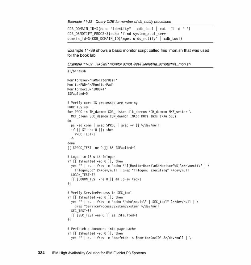
Example 11-38 Query CDB for number of ds_notify processes
CDB_DOMAIN_ID=$(echo "identity" | cdb_tool | cut -f1 -d ' ')CDB_DSNOTIFY_PROCS=$(echo "find system_appl_serv domain_id=${CDB_DOMAIN_ID}\nget u ds_notify" | cdb_tool)
Example 11-39 shows a basic monitor script called fnis_mon.sh that was used for the book lab.
Example 11-39 HACMP monitor script /opt/FileNet/ha_scripts/fnis_mon.sh
#!/bin/ksh
MonitorUser="HAMonitorUser"MonitorPWD="HAMonitorPwd"MonitorDocID="100074"ISFaulted=0
# Verify core IS processes are runningPROC_TEST=0for PROC in TM_daemon COR_Listen ilk_daemon NCH_daemon MKF_writer \ MKF_clean SEC_daemon CSM_daemon INXbg DOCs INXs INXu SECsdo ps -eo comm | grep $PROC | grep -v $$ >/dev/null if [[ $? -ne 0 ]]; then PROC_TEST=1 fidone[[ $PROC_TEST -ne 0 ]] && ISFaulted=1
# Logon to IS with fnlogonif [[ ISFaulted -eq 0 ]]; then yes "" | su - fnsw -c "echo \"${MonitorUser}\n${MonitorPWD}\n\n\nexit\" | \ fnlogon;cd" 2>/dev/null | grep "fnlogon: executing" >/dev/null LOGON_TEST=$? [[ $LOGON_TEST -ne 0 ]] && ISFaulted=1fi
# Verify ServiceProcess in SEC_toolif [[ ISFaulted -eq 0 ]]; then yes "" | su - fnsw -c "echo \"who\nquit\" | SEC_tool" 2>/dev/null | \ grep "ServiceProcess:System:System" >/dev/null SEC_TEST=$? [[ $SEC_TEST -ne 0 ]] && ISFaulted=1fi
# Prefetch a document into page cacheif [[ ISFaulted -eq 0 ]]; then yes "" | su - fnsw -c "docfetch -s $MonitorDocID" 2>/dev/null | \
334 IBM High Availability Solution for IBM FileNet P8 Systems

grep "$MonitorDocID retrieved" >/dev/null PREFETCH_TEST=$? [[ $PREFETCH_TEST -ne 0 ]] && ISFaulted=1fi
# Return status of testsif [[ $ISFaulted -ne 0 ]]; then exit 1 # IS may have a problemelse exit 0 # IS is runningfi
Automatic synchronizationAs a last step, when IS is installed and configured on all cluster nodes, you must add local scripts and configuration files to an HACMP File Collection. This way, HACMP keeps local files in sync between cluster nodes. To set up a File Collection, see “HACMP File Collection” on page 362.
11.2.3 Integrating an existing IS into HACMP
You can convert an existing IS system to an HACMP cluster.
However, we prefer a fresh installation of both cluster nodes (and a later migration of existing data), because it requires less downtime, and the cluster can be tested in more detail before being taken into production.
The following high-level steps are necessary to reconfigure the original server as node 1 and to install IS on node 2 of the new cluster:
1. Install and configure HACMP on both cluster nodes.
2. Make sure that UID and GID of the IS users and groups match on both nodes.
3. Move the /fnsw/local, /msar1, and /backup file systems to the shared disks of the cluster. Disable the auto varyon of the shared VG, and disable auto mount of the shared file systems on both nodes.
4. Change the IP address of IS to the service address of the RG. Alternatively, use the existing IS address as the service address.
5. Disable the autostart of IS from /etc/inittab.
Moving file systems to a SANThe files in the /fnsw/local file system can be copied to a separate mount point on the shared VG, and then, the shared file system is mounted in place of the existing local FS. If the old and new file system cannot be mounted concurrently,
Chapter 11. Image Services implementation 335
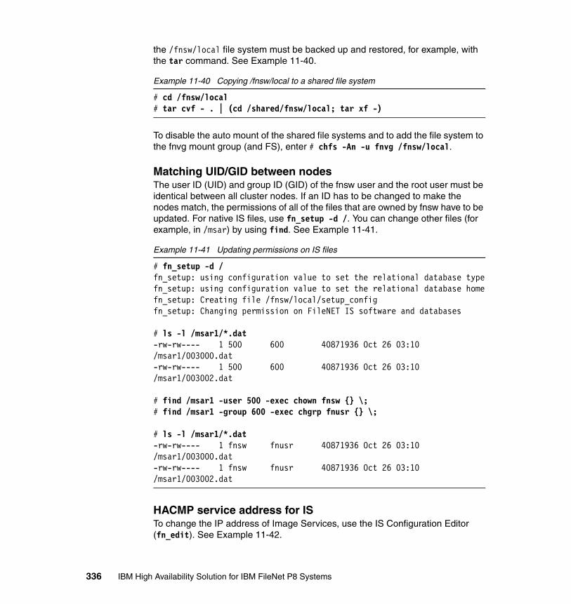
the /fnsw/local file system must be backed up and restored, for example, with the tar command. See Example 11-40.
Example 11-40 Copying /fnsw/local to a shared file system
# cd /fnsw/local# tar cvf - . | (cd /shared/fnsw/local; tar xf -)
To disable the auto mount of the shared file systems and to add the file system to the fnvg mount group (and FS), enter # chfs -An -u fnvg /fnsw/local.
Matching UID/GID between nodesThe user ID (UID) and group ID (GID) of the fnsw user and the root user must be identical between all cluster nodes. If an ID has to be changed to make the nodes match, the permissions of all of the files that are owned by fnsw have to be updated. For native IS files, use fn_setup -d /. You can change other files (for example, in /msar) by using find. See Example 11-41.
Example 11-41 Updating permissions on IS files
# fn_setup -d /fn_setup: using configuration value to set the relational database typefn_setup: using configuration value to set the relational database homefn_setup: Creating file /fnsw/local/setup_configfn_setup: Changing permission on FileNET IS software and databases
# ls -l /msar1/*.dat-rw-rw---- 1 500 600 40871936 Oct 26 03:10 /msar1/003000.dat-rw-rw---- 1 500 600 40871936 Oct 26 03:10 /msar1/003002.dat
# find /msar1 -user 500 -exec chown fnsw {} \;# find /msar1 -group 600 -exec chgrp fnusr {} \;
# ls -l /msar1/*.dat-rw-rw---- 1 fnsw fnusr 40871936 Oct 26 03:10 /msar1/003000.dat-rw-rw---- 1 fnsw fnusr 40871936 Oct 26 03:10 /msar1/003002.dat
HACMP service address for ISTo change the IP address of Image Services, use the IS Configuration Editor (fn_edit). See Example 11-42.
336 IBM High Availability Solution for IBM FileNet P8 Systems
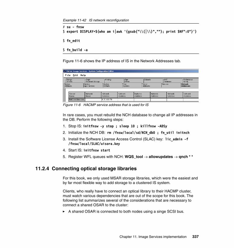
Example 11-42 IS network reconfiguration
# su - fnsw$ export DISPLAY=$(who am i|awk '{gsub("\\(|\\)",""); print $NF":0"}')
$ fn_edit
$ fn_build -a
Figure 11-6 shows the IP address of IS in the Network Addresses tab.
Figure 11-6 HACMP service address that is used for IS
In rare cases, you must rebuild the NCH database to change all IP addresses in the DB. Perform the following steps:
1. Stop IS: initfnsw -y stop ; sleep 10 ; killfnsw -ADSy
2. Initialize the NCH DB: rm /fnsw/local/sd/NCH_db0 ; fn_util initnch
3. Install the Software License Access Control (SLAC) key: lic_admin -f /fnsw/local/SLAC/uisora.key
4. Start IS: initfnsw start
5. Register WFL queues with NCH: WQS_tool → allowupdates → qnch * *
11.2.4 Connecting optical storage libraries
For this book, we only used MSAR storage libraries, which were the easiest and by far most flexible way to add storage to a clustered IS system.
Clients, who really have to connect an optical library to their HACMP cluster, must watch various dependencies that are out of the scope for this book. The following list summarizes several of the considerations that are necessary to connect a shared OSAR to the cluster:
� A shared OSAR is connected to both nodes using a singe SCSI bus.
Chapter 11. Image Services implementation 337

� “Y” cables (also know as “V” cables) or “inline-terminated” cables must be used, so the bus can be disconnected from a failed node for maintenance and is still operational.
� Each node requires a unique SCSI ID on its SCSI adapter, for example, node 1 = SCSI ID 5 and node 2 = SCSI ID 6.
� Avoid SCSI ID 7 altogether (if possible), because this SCSI ID 7 is the default ID for SCSI adapters when a server boots in maintenance mode. If a cluster node is booted in maintenance mode, and SCSI ID 7 is used on another node on the same bus, the node to be booted must be disconnected from its Y cable first; otherwise, there are two conflicting SCSI IDs 7.
� When assigning SCSI IDs, observe the SCSI priorities:7 > 6 > 5 > 4 > 3 > 2 > 1 > 0 > 15 > 14 > 13 > 12 > 11 > 10 > 9 > 8In practice, the following assignment is optimal with wide SCSI addressing, which is available since IS Version 4.1.1 on AIX (provided that all devices support wide SCSI). Because all drives share a common SCSI bus, performance might be limited by the bus transfer speed:
– SCSI Bus 1 (Priority: SCSI adapter > Arm > Drive):
• SCSI ID 7: N/C (default for server maintenance mode)• SCSI ID 6: Node 2 SCSI adapter• SCSI ID 5: Node 1 SCSI adapter• SCSI ID 4: OSAR Robotic Arm• SCSI ID 3: OSAR Drive # 1• SCSI ID 2: OSAR Drive # 2• SCSI ID 1: OSAR Drive # 3• SCSI ID 0: OSAR Drive # 4• SCSI ID 15: OSAR Drive # 5• SCSI ID 14: OSAR Drive # 6• SCSI ID 13: OSAR Drive # 7• SCSI ID 12: OSAR Drive # 8• SCSI ID 11: OSAR Drive # 9• SCSI ID 10: OSAR Drive # 10
� Narrow SCSI addressing requires to use two SCSI busses for libraries with more than four drives. In that case, a complete separate SCSI bus is required, including all SCSI adapters, cables, and terminators:
– SCSI Bus 1 (Priority: SCSI adapter > Arm > Drive):
• SCSI ID 7: Not used (default for server maintenance mode)• SCSI ID 6: Node 2 SCSI adapter• SCSI ID 5: Node 1 SCSI adapter• SCSI ID 4: OSAR Robotic Arm• SCSI ID 3: OSAR Drive # 1• SCSI ID 2: OSAR Drive # 2
338 IBM High Availability Solution for IBM FileNet P8 Systems

• SCSI ID 1: OSAR Drive # 3• SCSI ID 0: OSAR Drive # 4
– SCSI Bus 2 (if applicable):
• SCSI ID 6: Node 2 SCSI adapter• SCSI ID 7: Node 1 SCSI adapter (use ID 5 if fewer than 10 drives)• SCSI ID 5: OSAR Drive # 5• SCSI ID 4: OSAR Drive # 6• SCSI ID 3: OSAR Drive # 7• SCSI ID 2: OSAR Drive # 8• SCSI ID 1: OSAR Drive # 9• SCSI ID 0: OSAR Drive # 10
� Each SCSI bus must be terminated on both ends (only). You might need to remove SCSI terminators on SCSI adapters, if the adapters are not auto terminating.
� If SCSI expanders, such as the Paralan MM16, are used on the shared SCSI bus, you might need to disable internal terminators.
� You must carefully watch the maximum length of the SCSI bus. All cables and devices (including the OSAR and all Y-cables) contribute to the total bus length.
� As of IS 4.1.1, all platforms support the logical unit number (LUN) mode, including the 64-bit AIX platform. However, performance of LUN mode SCSI is evidently inferior to target mode SCSI.
� HP optical libraries do not support LUN mode in clustered environments.
� Consult IBM FileNet Image Services, OSAR Cable Tool, 2008-07-22, when planning a supported configuration.
� Refer to IBM FileNet Image Services, Version 4.1, Release Notes, GC31-5578-03, which also contains important information regarding the clustering of OSARs.
� Whenever an updated fnsod driver is installed (for example, by an IS patch), you must run the /fnsw/bin/fnsod.install command on all cluster nodes.
� Use extreme caution when planning to extend shared busses with SCSI expanders (for example, from Paralan, Apcon, Blackbox, and so on). Only a few models handle the optical library SCSI command set correctly, in particular when returning sense data in case of a failure. The stability and the performance of the attached storage library is impaired with increasing cable length.
Figure 11-7 illustrates the connection of a shared OSAR with HACMP.
Chapter 11. Image Services implementation 339

Figure 11-7 Connection of a shared OSAR with HACMP
SCSI-attached optical libraries usually also require special handling during HACMP cluster takeovers.
SCSI reserves might exist and have to be broken when starting a resource group on a cluster node, for example, by issuing a SCSI reset. With HACMP, the cl_scdiskreset command in /usr/es/sbin/cluster/events/utils can be used to reset the SCSI bus. On HP-UX, Image Services provides a busreset and devreset command in /fnsw/bin.
A SCSI bus reset can also be initiated from a small C program calling:
� ioctl (ScsiDevice, SIOC_RESET_BUS, 0) on HP-UX� ioctl (ScsiDevice, RESET_ALL, 0) on the Solaris platform
An alternative way of connecting a shared OSAR is to place the device in between the cluster nodes, in the middle of the SCSI chain, as shown in Figure 11-8.
may need to
disable termination
Node 1(active)
Node 2(idle standby)
Y-cable
Terminator
Y-cable
shortcable
(internal)Terminator
SCSI ID 5
SCSI ID 6
Optical Library
longcable
SCSI IDs4, 3, 2, 1, 0
(4: robotic arm)
340 IBM High Availability Solution for IBM FileNet P8 Systems

Figure 11-8 Shared OSAR in between the cluster nodes
11.3 High availability test for IS cluster
This section describes the tests that were performed for our case study to verify that the clustered IS is in fact highly available and is capable of resuming operations after a failure.
11.3.1 Restart and takeover tests
You must test the HACMP functionality after every change to the cluster, as well as at fixed intervals, for example, once every six months.
The takeover tests need to include IS server and IS client application tests. For the most part, IS users stay connected and are not required to log on again after IS has been restarted on the standby node. Users, who were only running an IDM Find query, might be required to restart. Batches that were in the process of being scanned with Capture Professional usually have to be deleted and re-scanned after a takeover.
may need to
disable termination
Node 1(active)
Node 2(idle standby)
Optical Library
Y-cable
Terminator
SCSI ID 5
SCSI ID 6
Y-cable
Terminator
SCSI IDs4, 3, 2, 1, 0
(4: robotic arm)
Chapter 11. Image Services implementation 341

Other applications, such as the IS Resource Adapter (ISRA), P8 Content Federation Services for IS (CFS-IS), and customer applications (for example, based on ISTK or ISRA) must be tested, and their reaction to the HACMP takeover (or IS restart for that matter) needs to be noted.
The following cluster tests were carried out successfully at our lab. With every test, the client connections from IDM Desktop (IDM-DT) and from the P8 Content Engine (CE) through CFS-IS were tested.
Takeover caused by node failureTable 11-9 on page 343 details the automatic takeover test that we performed.
342 IBM High Availability Solution for IBM FileNet P8 Systems
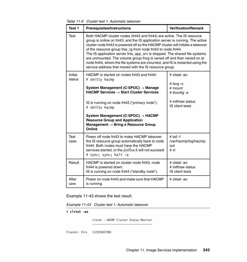
Table 11-9 Cluster test 1: Automatic takeover
Example 11-43 shows the test result.
Example 11-43 Cluster test 1: Automatic takeover
# clstat -ao
clstat - HACMP Cluster Status Monitor -------------------------------------
Cluster: fnis (1222565798)
Test 1 Prerequisites/Instructions Verification/Remark
Test Both HACMP cluster nodes (fnl43 and fnl44) are active. The IS resource group is online on fnl43, and the IS application server is running. The active cluster node fnl43 is powered off so the HACMP cluster will initiate a takeover of the resource group fnis_rg from node fnl43 to node fnl44.The IS application server fnis_app_srv is stopped. The shared file systems are unmounted. The volume group fnvg is varied off and then varied on at node fnl44, where the file systems are mounted, and IS is restarted using the service address that moved with the IS resource group.
Initial status
HACMP is started on nodes fnl43 and fnl44:# smitty hacmp
System Management (C-SPOC) → Manage HACMP Services → Start Cluster Services
IS is running on node fnl43 (“primary node”):# smitty hacmp
System Management (C-SPOC) → HACMP Resource Group and Application Management → Bring a Resource Group Online
# clstat -ao
# lsvg -o# mount# ifconfig -a
# initfnsw statusIS client tests
Test case
Power off node fnl43 to make HACMP takeover the IS resource group automatically back to node fnl44. Both nodes must have the HACMP services started, or the failback will not succeed:# sync; sync; halt -q
# tail -f /var/hacmp/log/hacmp.out# vl
Result HACMP is started on cluster node fnl43, node fnl44 is powered down.IS is running on node fnl44 (“standby node”).
# clstat -ao# initfnsw statusIS client tests
After care
Power on node fnl43 and make sure that HACMP is running.
# clstat -ao
Chapter 11. Image Services implementation 343

State: UP Nodes: 2 SubState: STABLE
Node: fnl43 State: UP Interface: fnl43-bt1 (2) Address: 10.10.10.53 State: UP Interface: fnl43_vpath0_01 (0) Address: 0.0.0.0 State: UP Interface: fnis (2) Address: 9.30.188.78 State: UP Interface: fnl43-hs03 (1) Address: 10.0.3.53 State: UP Resource Group: fnis_rg State: On line
Node: fnl44 State: UP Interface: fnl44-bt1 (2) Address: 10.10.10.54 State: UP Interface: fnl44_vpath0_01 (0) Address: 0.0.0.0 State: UP Interface: fnl44-hs03 (1) Address: 10.0.3.54 State: UP
# sync; sync; halt -q # This will stop the node close to power off!
# clstat -ao
clstat - HACMP Cluster Status Monitor -------------------------------------
Cluster: fnis (1222565798)
State: UP Nodes: 2 SubState: STABLE
Node: fnl43 State: DOWN Interface: fnl43-bt1 (2) Address: 10.10.10.53 State: DOWN Interface: fnl43_vpath0_01 (0) Address: 0.0.0.0 State: DOWN Interface: fnl43-hs03 (1) Address: 10.0.3.53 State: DOWN
Node: fnl44 State: UP Interface: fnl44-bt1 (2) Address: 10.10.10.54 State: UP Interface: fnl44_vpath0_01 (0) Address: 0.0.0.0 State: UP Interface: fnis (2) Address: 9.30.188.78 State: UP Interface: fnl44-hs03 (1) Address: 10.0.3.54 State: UP Resource Group: fnis_rg State: On line
344 IBM High Availability Solution for IBM FileNet P8 Systems

# pg /var/hacmp/log/hacmp.out[...]Terminating processes...Initializing FileNet software...Starting index database...Starting permanent database...Starting transient database...Starting security database...Starting Courier...Starting NCH_daemon...Starting the Security Daemon...Optimizing SEC database...please wait...Starting INXbg...Starting INXu...Starting document services...Starting batch entry services...Starting print services...Startup of FileNet software initiated. See event log for detailed status.[...]
# su - fnsw# initfnsw status
Software status for host 'fnl43.svl.ibm.com' (operating system = AIX): Software started since 11/09/08 20:58:12
Manual move of IS resource groupTable 11-10 on page 346 details our second test, manual takeover.
Chapter 11. Image Services implementation 345
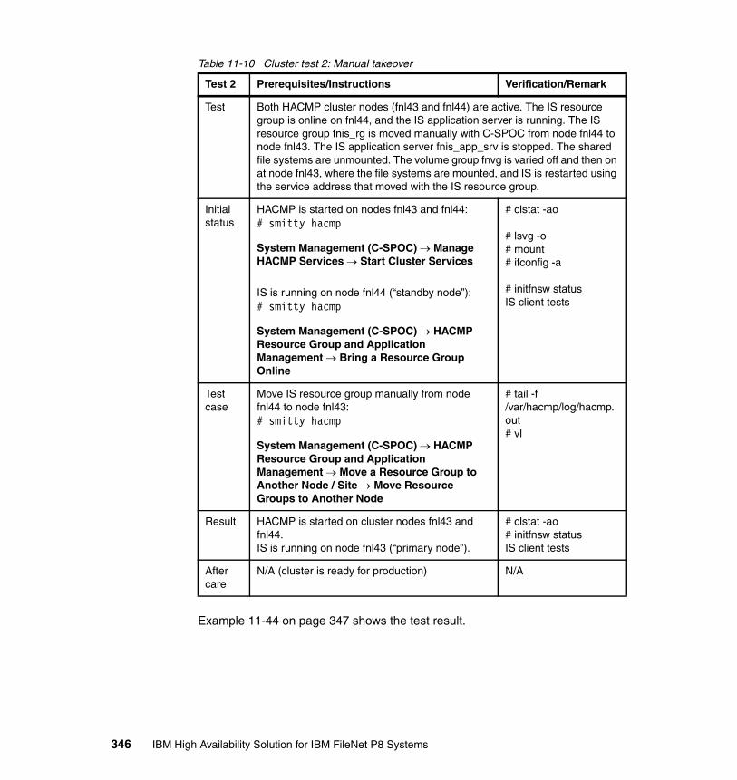
Table 11-10 Cluster test 2: Manual takeover
Example 11-44 on page 347 shows the test result.
Test 2 Prerequisites/Instructions Verification/Remark
Test Both HACMP cluster nodes (fnl43 and fnl44) are active. The IS resource group is online on fnl44, and the IS application server is running. The IS resource group fnis_rg is moved manually with C-SPOC from node fnl44 to node fnl43. The IS application server fnis_app_srv is stopped. The shared file systems are unmounted. The volume group fnvg is varied off and then on at node fnl43, where the file systems are mounted, and IS is restarted using the service address that moved with the IS resource group.
Initial status
HACMP is started on nodes fnl43 and fnl44:# smitty hacmp
System Management (C-SPOC) → Manage HACMP Services → Start Cluster Services
IS is running on node fnl44 (“standby node”):# smitty hacmp
System Management (C-SPOC) → HACMP Resource Group and Application Management → Bring a Resource Group Online
# clstat -ao
# lsvg -o# mount# ifconfig -a
# initfnsw statusIS client tests
Test case
Move IS resource group manually from node fnl44 to node fnl43:# smitty hacmp
System Management (C-SPOC) → HACMP Resource Group and Application Management → Move a Resource Group to Another Node / Site → Move Resource Groups to Another Node
# tail -f /var/hacmp/log/hacmp.out# vl
Result HACMP is started on cluster nodes fnl43 and fnl44.IS is running on node fnl43 (“primary node”).
# clstat -ao# initfnsw statusIS client tests
After care
N/A (cluster is ready for production) N/A
346 IBM High Availability Solution for IBM FileNet P8 Systems

Example 11-44 Cluster test 2: Manual takeover
# clstat -ao
clstat - HACMP Cluster Status Monitor -------------------------------------
Cluster: fnis (1222565798)
State: UP Nodes: 2 SubState: STABLE
Node: fnl43 State: UP Interface: fnl43-bt1 (2) Address: 10.10.10.53 State: UP Interface: fnl43_vpath0_01 (0) Address: 0.0.0.0 State: UP Interface: fnl43-hs03 (1) Address: 10.0.3.53 State: UP
Node: fnl44 State: UP Interface: fnl44-bt1 (2) Address: 10.10.10.54 State: UP Interface: fnl44_vpath0_01 (0) Address: 0.0.0.0 State: UP Interface: fnis (2) Address: 9.30.188.78 State: UP Interface: fnl44-hs03 (1) Address: 10.0.3.54 State: UP Resource Group: fnis_rg State: On line
# smitty hacmp
System Management (C-SPOC) → HACMP Resource Group and Application Management → Move a Resource Group to Another Node / Site → Move Resource Groups to Another Node
or
# cd /usr/es/sbin/cluster/utilities# clRGmove -s false -m -i -g fnis_rg -n fnl43
Attempting to move resource group fnis_rg to node fnl43.
Waiting for the cluster to process the resource group movement request..........
Waiting for the cluster to stabilize..............
Resource group movement successful.Resource group fnis_rg is online on node fnl43.
Cluster Name: fnis
Chapter 11. Image Services implementation 347

Resource Group Name: fnis_rgNode State---------------------------- ---------------fnl43 ONLINEfnl44 OFFLINE
# clstat -ao
clstat - HACMP Cluster Status Monitor -------------------------------------
Cluster: fnis (1222565798)
State: UP Nodes: 2 SubState: STABLE
Node: fnl43 State: UP Interface: fnl43-bt1 (2) Address: 10.10.10.53 State: UP Interface: fnl43_vpath0_01 (0) Address: 0.0.0.0 State: UP Interface: fnis (2) Address: 9.30.188.78 State: UP Interface: fnl43-hs03 (1) Address: 10.0.3.53 State: UP Resource Group: fnis_rg State: On line
Node: fnl44 State: UP Interface: fnl44-bt1 (2) Address: 10.10.10.54 State: UP Interface: fnl44_vpath0_01 (0) Address: 0.0.0.0 State: UP Interface: fnl44-hs03 (1) Address: 10.0.3.54 State: UP
# pg /var/hacmp/log/hacmp.out[...]Terminating processes...Initializing FileNet software...Starting index database...Starting permanent database...Starting transient database...Starting security database...Starting Courier...Starting NCH_daemon...Starting the Security Daemon...Optimizing SEC database...please wait...Starting INXbg...Starting INXu...Starting document services...Starting batch entry services...Starting print services...Startup of FileNet software initiated. See event log for detailed status.
348 IBM High Availability Solution for IBM FileNet P8 Systems

[...]
# su - fnsw# initfnsw status
Software status for host 'fnl43.svl.ibm.com' (operating system = AIX): Software started since 11/09/08 20:58:12
Restart of IS by monitorTable 11-11 details the third test of triggering an IS restart by a monitor.
Table 11-11 Cluster test 3: Restart of IS triggered by a monitor
Test 3 Prerequisites/Instructions Verification/Remark
Test Both HACMP cluster nodes (fnl43 and fnl44) are active. The IS resource group is online on fnl43, and the IS application server is running. One of the processes watched by the IS application server monitor is ended to force a restart of IS on node fnl43. The IS application server fnis_app_srv is stopped and restarted. No takeover to node fnl44 will occur.
Initial status
HACMP is started on nodes fnl43 and fnl44: # smitty hacmp
System Management (C-SPOC) → Manage HACMP Services → Start Cluster Services
IS is running on node fnl43 (“primary node”):
# smitty hacmp
System Management (C-SPOC) → HACMP Resource Group and Application Management → Bring a Resource Group Online
# clstat -ao
# lsvg -o# mount# ifconfig -a
# initfnsw statusIS client tests
Test case
End the SEC_daemon process:
# ps -ef | grep SEC_daemon | grep -v $$# kill -9 <PID>
# tail -f /var/hacmp/log/hacmp.out# vl
Result IS is restarted on the current node (fnl43), and no takeover occurs.
# clstat -ao# initfnsw statusIS client tests
After care
N/A (cluster is ready for production)
Chapter 11. Image Services implementation 349
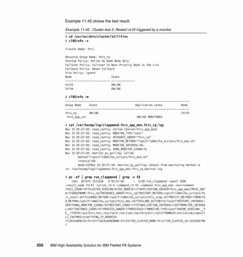
Example 11-45 shows the test result.
Example 11-45 Cluster test 3: Restart of IS triggered by a monitor
# cd /usr/es/sbin/cluster/utilities# clRGinfo -v
Cluster Name: fnis
Resource Group Name: fnis_rgStartup Policy: Online On Home Node OnlyFallover Policy: Fallover To Next Priority Node In The ListFallback Policy: Never FallbackSite Policy: ignoreNode State---------------------------- ---------------fnl43 ONLINEfnl44 ONLINE
# clRGinfo -m------------------------------------------------------------------------------Group Name State Application state Node------------------------------------------------------------------------------fnis_rg ONLINE fnl43 fnis_app_srv ONLINE MONITORED
# cat /var/hacmp/log/clappmond.fnis_app_mon.fnis_rg.logNov 10 02:27:50: read_config: Called [Server=fnis_app_mon]Nov 10 02:27:50: read_config: MONITOR_TYPE="user"Nov 10 02:27:50: read_config: RESOURCE_GROUP="fnis_rg"Nov 10 02:27:50: read_config: MONITOR_METHOD="/opt/FileNet/ha_scripts/fnis_mon.sh"Nov 10 02:27:50: read_config: MONITOR_INTERVAL=60.Nov 10 02:27:50: read_config: HUNG_MONITOR_SIGNAL=9.Nov 10 02:27:50: monitor_by_polling: Called method="/opt/FileNet/ha_scripts/fnis_mon.sh" interval=60 mode=(0)Nov 10 02:27:50: monitor_by_polling: Output from monitoring method is in: /var/hacmp/log/clappmond.fnis_app_mon.fnis_rg.monitor.log
# ps -ef | grep run_clappmond | grep -v $$ root 827570 1511630 0 02:27:50 - 0:00 run_clappmond -sport 1000 -result_node fnl43 -script_id 0 -command_id 10 -command fnis_app_mon -environment ?FAIL_COUNT=0??CLUSTER_VERSION=9??GS_NODEID=1??APPLICATION_SERVER=fnis_app_mon??MISC_DATA=??GROUPNAME=fnis_rg??RESOURCE_GROUP=fnis_rg??RESTART_METHOD=/opt/FileNet/ha_scripts/fnis_start.sh??CLEANUP_METHOD=/opt/FileNet/ha_scripts/fnis_stop.sh??NOTIFY_METHOD=??MONITOR_METHOD=/opt/FileNet/ha_scripts/fnis_mon.sh??FAILURE_ACTION=fallover??RESTART_INTERVAL=594??HUNG_MONITOR_SIGNAL=9??RESTART_COUNT=1??STABILIZATION_INTERVAL=120??MONITOR_INTERVAL=60??INSTANCE_COUNT=0??PROCESS_OWNER=??PROCESSES=??MONITOR_TYPE=user??HACMP_VERSION=__PE__??PATH=/usr/bin:/etc:/usr/sbin:/usr/ucb:/usr/bin/X11:/sbin??ODMDIR=/etc/es/objrepos??LC_FASTMSG=true??PING_IP_ADDRESS= ??LOCALNODEID=fnl43??LOCALNODENAME=fnl43??CM_CLUSTER_NAME=fnis??CM_CLUSTER_ID=1222565798?
350 IBM High Availability Solution for IBM FileNet P8 Systems

# /opt/FileNet/ha_scripts/fnis_mon.sh ; echo $?0
# ps -ef | grep SEC_daemon | grep -v $$ fnsw 1368254 1 0 02:26:26 - 0:00 SEC_daemon
# kill -9 1368254
# /opt/FileNet/ha_scripts/fnis_mon.sh ; echo $?1
# pg/var/hacmp/log/clstrmgr.debug[...]Mon Nov 10 02:31:58 GetRmCtrlMsg: Called, state=ST_STABLEMon Nov 10 02:31:58 GetRmCtrlMsg: RM_ExitStatus msg received, status=2, RP=fnis_app_monMon Nov 10 02:31:58 ResGroupList::monitorExit(): monitor fnis_app_mon, resource id 10, pid 737480, exit status 2Mon Nov 10 02:31:58 ResourceGroup::monitorExit(fnis_rg)Mon Nov 10 02:31:58 ResourceList::monitorExit(5)Mon Nov 10 02:31:58 Resource::monitorExit(fnis_app_mon)Mon Nov 10 02:31:58 AppmonList::monitorExit: looking for monitor with name fnis_app_mon and pid 737480Mon Nov 10 02:31:58 monitor 0 is fnis_app_mon, pid 737480Mon Nov 10 02:31:58 Appmon::clappmondExit(fnis_app_mon): Called, monitorState 11, exit status 2Mon Nov 10 02:31:58 umt::addAction() CalledMon Nov 10 02:31:58 clappmondExit(fnis_app_mon): retries left (1 of 1), setting OnlineMonitorFailedMon Nov 10 02:31:58 Appmon::setAppState: setting application fnis_app_mon(10) state 8Mon Nov 10 02:31:58 setAppState: Running FSM with NEW_EVENTMon Nov 10 02:31:58 FSMrun: started (0) for transition [ST_STABLE][EV_NEW_EVENT]Mon Nov 10 02:31:58 FSMrun: running state = ST_STABLE, FSM-event = EV_NEW_EVENTMon Nov 10 02:31:58 handleNewEvent: Called, state=ST_STABLE, new event=TE_SERVER_RESTART, new node=1[...]
# pg /var/hacmp/log/hacmp.out[...]Nov 10 02:31:59 EVENT START: server_restart fnl43 10 fnis_app_mon[...]HACMP Event SummaryEvent: TE_SERVER_RESTARTStart time: Mon Nov 10 02:31:59 2008End time: Mon Nov 10 02:32:32 2008[...]Terminating processes...Initializing FileNet software...Starting index database...Starting permanent database...Starting transient database...Starting security database...Starting Courier...
Chapter 11. Image Services implementation 351
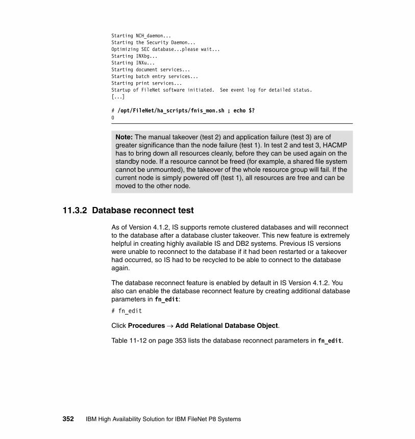
Starting NCH_daemon...Starting the Security Daemon...Optimizing SEC database...please wait...Starting INXbg...Starting INXu...Starting document services...Starting batch entry services...Starting print services...Startup of FileNet software initiated. See event log for detailed status.[...]
# /opt/FileNet/ha_scripts/fnis_mon.sh ; echo $?0
11.3.2 Database reconnect test
As of Version 4.1.2, IS supports remote clustered databases and will reconnect to the database after a database cluster takeover. This new feature is extremely helpful in creating highly available IS and DB2 systems. Previous IS versions were unable to reconnect to the database if it had been restarted or a takeover had occurred, so IS had to be recycled to be able to connect to the database again.
The database reconnect feature is enabled by default in IS Version 4.1.2. You also can enable the database reconnect feature by creating additional database parameters in fn_edit:
# fn_edit
Click Procedures → Add Relational Database Object.
Table 11-12 on page 353 lists the database reconnect parameters in fn_edit.
Note: The manual takeover (test 2) and application failure (test 3) are of greater significance than the node failure (test 1). In test 2 and test 3, HACMP has to bring down all resources cleanly, before they can be used again on the standby node. If a resource cannot be freed (for example, a shared file system cannot be unmounted), the takeover of the whole resource group will fail. If the current node is simply powered off (test 1), all resources are free and can be moved to the other node.
352 IBM High Availability Solution for IBM FileNet P8 Systems

Table 11-12 Database reconnect parameters in fn_edit
In Example 11-46, the IS Configuration Editor (fn_edit) is started to add the database reconnect parameters by clicking the Procedures tab.
Example 11-46 Database reconnect configuration in fn_edit
# su - fnsw$ export DISPLAY=$(who am i|awk '{gsub("\\(|\\)",""); print $NF":0"}')
$ fn_edit
$ fn_build -a
Figure 11-9 shows the additional (optional) db_reconnect_* parameters in the Relational Databases tab, RDB Objects subtab of fn_edit.
Figure 11-9 DB reconnect configuration in fn_edit
The database reconnect tests were carried out with and without the db_reconnect_* entries in fn_edit, with the same results: IS does in fact reconnect after a takeover of the database, but it also logs errors in the IS elog.
Object name Location Default Remark
db_reconnect_disabled 0 0 1 disables reconnects
db_reconnect_timeout 600 600 Retries up to 10 minutes
db_reconnect_interval 10 10 Retries every 10 seconds
Chapter 11. Image Services implementation 353

For the tests, an IDM Find query was started, and a takeover of the database cluster was forced (by stopping the current database node with halt -q). In most cases, the current query had to be repeated after the reconnect.
The IS elog did not show the expected <121,0,41> DBMS is not available errors, but reported <121,9,30108> DB2 SQL30108N: A connection failed but has been re-established. See Example 11-47.
Example 11-47 Database reconnect tests with a DB2 cluster
# vl # more /fnsw/local/logs/elogs/elog$(date +"%Y%m%d")[...]2008/10/26 02:05:14.873 121,9,30108 <fnsw> INXbg -s IndexServer (1200182.1.28 0x125036.1) ... [SERIOUS]Error in GDBD_exec: SQLExecute, STMT 65537 (&20073170) (../src/GDBD.c, VERSION 4.1.1.0, @3394).SQLSTATE = 08506, NativeError = -30108,ErrorMsg = '[IBM][CLI Driver][DB2/AIX64] SQL30108N A connection failed but has been re-established. The hostname or IP address is "9.30.188.80" and the service name or port number is "50010". Special registers may or may not be re-attempted (Reason code = "1"). SQLSTATE=08506'
2008/10/26 02:05:25.487 121,9,30108 <fnsw> INXs (1282302.1.97 0x1390fe.1) ... [SERIOUS]Error in GDBD_exec: SQLExecute, STMT 65537 (&20025730) (../src/GDBD.c, VERSION 4.1.1.0, @3394).SQLSTATE = 08506, NativeError = -30108,ErrorMsg = '[IBM][CLI Driver][DB2/AIX64] SQL30108N A connection failed but has been re-established. The hostname or IP address is "9.30.188.80" and the service name or port number is "50010". Special registers may or may not be re-attempted (Reason code = "1"). SQLSTATE=08506'[...]
Depending on the current state of the IDM Desktop client and the current communication between IS and DB2, there where different errors in the IS elog:
[...]2008/10/26 02:49:33.594 90,0,12 <fnsw> INXs (1118330.1.97 0x11107a.1) ...query: SELECT f_docnumber,f_docclassnumber,f_entrydate,f_archivedate,f_deletedate,f_retentbase,f_retentdisp,f_retentoffset,f_pages,f_doctype,f_accessrights,f_docformat,f_doclocation,f_ce_os_id,f_accessrights_rd,f_accessrights_wr,f_accessrights_ax,a31,a32,a33,a34,a35,a36 FROM doctaba WHERE f_docnumber = :DOC err:30108[...]
or, in other cases:
[...]2008/10/26 02:05:25.487 155,209,215 <fnsw> COR_Listen -pt -s32769 -t3600 -d100 (934098.1029.61 0xe40d2.405) ... [WARNING]COR got Error in Ocor_snd, code=0
2008/10/26 02:05:25.488 155,209,217 <fnsw> INXs (1282302.1.97 0x1390fe.1) ... [WARNING]cor_PutPacket: connection terminated prematurely
354 IBM High Availability Solution for IBM FileNet P8 Systems
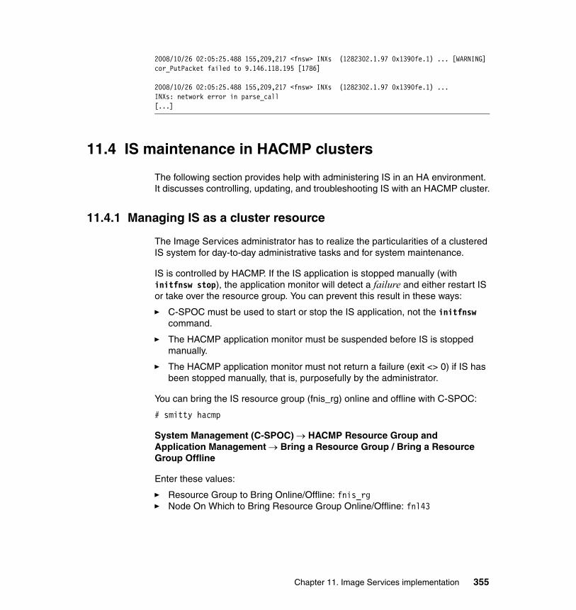
2008/10/26 02:05:25.488 155,209,217 <fnsw> INXs (1282302.1.97 0x1390fe.1) ... [WARNING]cor_PutPacket failed to 9.146.118.195 [1786]
2008/10/26 02:05:25.488 155,209,217 <fnsw> INXs (1282302.1.97 0x1390fe.1) ...INXs: network error in parse_call[...]
11.4 IS maintenance in HACMP clusters
The following section provides help with administering IS in an HA environment. It discusses controlling, updating, and troubleshooting IS with an HACMP cluster.
11.4.1 Managing IS as a cluster resource
The Image Services administrator has to realize the particularities of a clustered IS system for day-to-day administrative tasks and for system maintenance.
IS is controlled by HACMP. If the IS application is stopped manually (with initfnsw stop), the application monitor will detect a failure and either restart IS or take over the resource group. You can prevent this result in these ways:
� C-SPOC must be used to start or stop the IS application, not the initfnsw command.
� The HACMP application monitor must be suspended before IS is stopped manually.
� The HACMP application monitor must not return a failure (exit <> 0) if IS has been stopped manually, that is, purposefully by the administrator.
You can bring the IS resource group (fnis_rg) online and offline with C-SPOC:
# smitty hacmp
System Management (C-SPOC) → HACMP Resource Group and Application Management → Bring a Resource Group / Bring a Resource Group Offline
Enter these values:
� Resource Group to Bring Online/Offline: fnis_rg� Node On Which to Bring Resource Group Online/Offline: fnl43
Chapter 11. Image Services implementation 355
When HACMP cluster services are stopped on the active cluster node, the IS resource group can be placed in one of these states:
� Brought offline (IS is stopped, and the resource group is brought offline.)
� Moved (IS is stopped, the resource group is moved, and IS is started on another node.)
� Unmanaged (Cluster services terminate, and IS keeps running on this node.)
When HACMP cluster services are started on a node, IS will not start automatically, and it will not be failed back (moved) to this node, because of the configuration settings in SMIT:
# smitty hacmp
Click Extended Configuration → Extended Resource Configuration → HACMP Extended Resource Group Configuration → Change/Show a Resource Group.
Enter these values:
� Resource Group Name: fnis_rg� Participating Nodes (Default Node Priority): fnl43 fnl44� Startup Policy: Online On Home Node Only� Fallover Policy: Fallover To Next Priority Node In The List� Fallback Policy: Never Fallback
If an HACMP takeover is required, but you do not want the IS application started automatically on the standby node, disable the IS application server (AS) start script by adding exit 0 as the second line of the start script on both nodes. You must disable monitoring if IS is not started by the start script. Leave the stop script as is, because it is required for a successful takeover:
# vi /opt/FileNet/ha_scripts/fnis_start.sh
Change the start script as shown in Example 11-48.
Example 11-48 Disabling the AS start script for maintenance
#!/bin/kshexit 0[...]
You can suspend and resume the application monitor (fnis_app_mon) for the IS application server (fnis_app_srv) with C-SPOC:
# smitty hacmp
356 IBM High Availability Solution for IBM FileNet P8 Systems
Click System Management (C-SPOC) → HACMP Resource Group and Application Management → Suspend/Resume Application Monitoring → Suspend Application Monitoring / Resume Application Monitoring.
You can also disable the IS application monitor by adding exit 0 as the second line of the script. The monitor fails if the first line is not the shebang (“#!”) magic number.
Do not forget to re-enable the cluster scripts on all nodes after maintenance.
11.4.2 Overview of local and shared resources
Whenever maintenance is required with an IS cluster, it can either affect local or shared resources, or both.
It is extremely important to know the (possible) consequences of changes, for example, applying a patch, and to act upon them appropriately in the cluster. In general, everything that is changed on the local node has to be changed on the other node, as well. Changes to shared resources (for example, the /fnsw/local file system), have to be made from one of the cluster nodes only.
The IS Multi-Keyed File (MKF) Databases use both local and shared resources. The links to the data files are local (in /fnsw/dev/1) so they have to be kept in sync on both nodes, for example, when a database is expanded with a new data file. The data file raw devices (logical volumes) are shared on volume group fnvg.
Local IS resourcesChanges to local resources have to be made on both cluster nodes, for example, by running an update wizard on one node after the other, or by changing a configuration file on both nodes simultaneously.
IS install or update wizards for release updates or patches (SP/FP) must be run on both cluster nodes. If an OSAR is attached, you must run the fnsod.install script (AIX/Solaris only) after the installers to install the device drivers.
Table 11-13 lists the local resources that are updated for IS on the installation process.
Table 11-13 Local resources modified for IS
Local resource IS reference Updated by
/etc/group AIX groups (fnusr, fnop, fnadmin, and so forth)
AIX, IS (GA) installer
/etc/passwd AIX users (fnsw and so forth) AIX, IS (GA) installer
Chapter 11. Image Services implementation 357
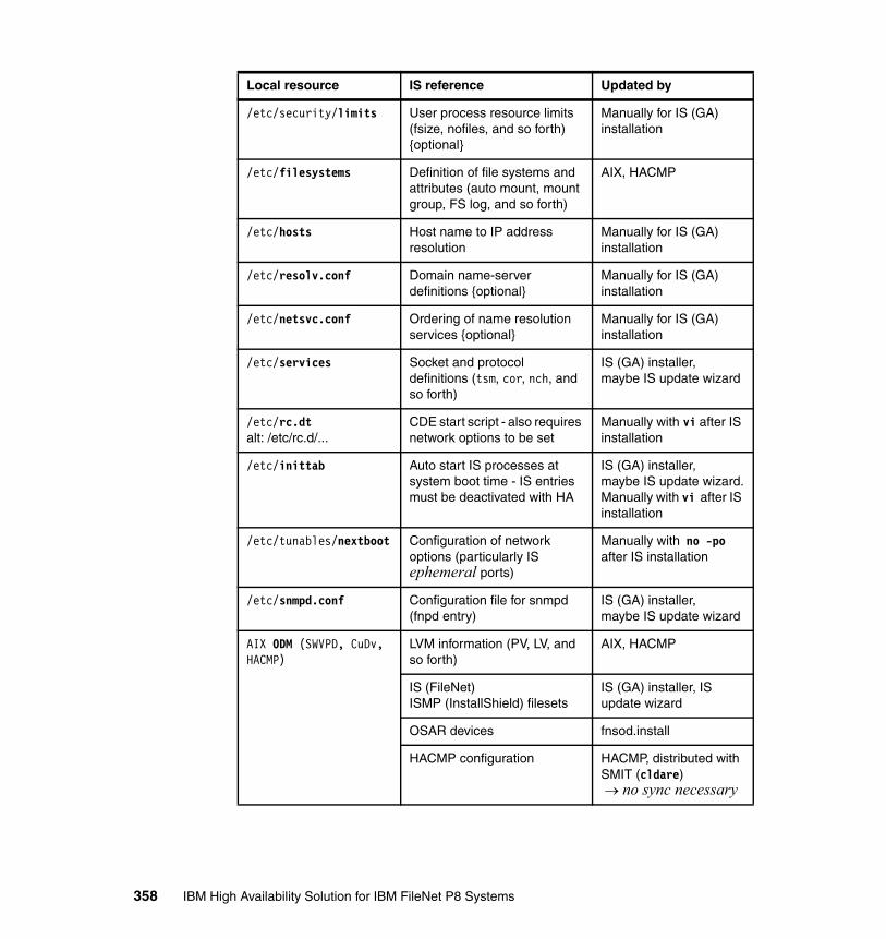
/etc/security/limits User process resource limits (fsize, nofiles, and so forth) {optional}
Manually for IS (GA) installation
/etc/filesystems Definition of file systems and attributes (auto mount, mount group, FS log, and so forth)
AIX, HACMP
/etc/hosts Host name to IP address resolution
Manually for IS (GA) installation
/etc/resolv.conf Domain name-server definitions {optional}
Manually for IS (GA) installation
/etc/netsvc.conf Ordering of name resolution services {optional}
Manually for IS (GA) installation
/etc/services Socket and protocol definitions (tsm, cor, nch, and so forth)
IS (GA) installer,maybe IS update wizard
/etc/rc.dtalt: /etc/rc.d/...
CDE start script - also requires network options to be set
Manually with vi after IS installation
/etc/inittab Auto start IS processes at system boot time - IS entries must be deactivated with HA
IS (GA) installer,maybe IS update wizard.Manually with vi after IS installation
/etc/tunables/nextboot Configuration of network options (particularly IS ephemeral ports)
Manually with no -po after IS installation
/etc/snmpd.conf Configuration file for snmpd (fnpd entry)
IS (GA) installer,maybe IS update wizard
AIX ODM (SWVPD, CuDv, HACMP)
LVM information (PV, LV, and so forth)
AIX, HACMP
IS (FileNet)ISMP (InstallShield) filesets
IS (GA) installer, IS update wizard
OSAR devices fnsod.install
HACMP configuration HACMP, distributed with SMIT (cldare)→ no sync necessary
Local resource IS reference Updated by
358 IBM High Availability Solution for IBM FileNet P8 Systems
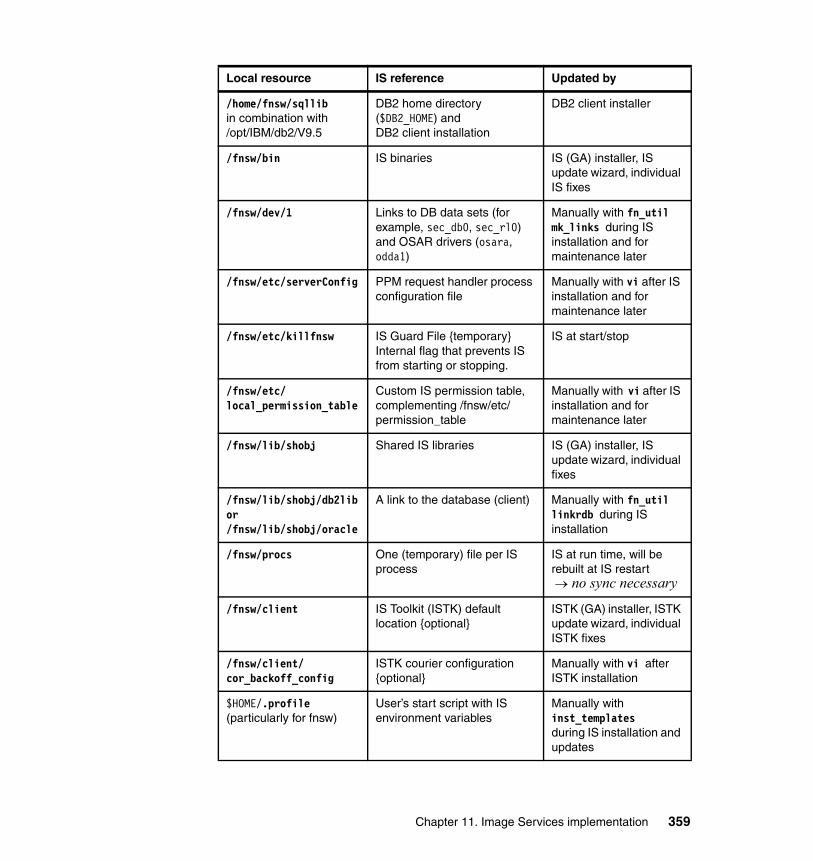
/home/fnsw/sqllibin combination with/opt/IBM/db2/V9.5
DB2 home directory ($DB2_HOME) andDB2 client installation
DB2 client installer
/fnsw/bin IS binaries IS (GA) installer, IS update wizard, individual IS fixes
/fnsw/dev/1 Links to DB data sets (for example, sec_db0, sec_rl0)and OSAR drivers (osara, odda1)
Manually with fn_util mk_links during IS installation and for maintenance later
/fnsw/etc/serverConfig PPM request handler process configuration file
Manually with vi after IS installation and for maintenance later
/fnsw/etc/killfnsw IS Guard File {temporary}Internal flag that prevents IS from starting or stopping.
IS at start/stop
/fnsw/etc/local_permission_table
Custom IS permission table, complementing /fnsw/etc/permission_table
Manually with vi after IS installation and for maintenance later
/fnsw/lib/shobj Shared IS libraries IS (GA) installer, IS update wizard, individual fixes
/fnsw/lib/shobj/db2libor/fnsw/lib/shobj/oracle
A link to the database (client) Manually with fn_util linkrdb during IS installation
/fnsw/procs One (temporary) file per IS process
IS at run time, will be rebuilt at IS restart→ no sync necessary
/fnsw/client IS Toolkit (ISTK) default location {optional}
ISTK (GA) installer, ISTK update wizard, individual ISTK fixes
/fnsw/client/cor_backoff_config
ISTK courier configuration {optional}
Manually with vi after ISTK installation
$HOME/.profile(particularly for fnsw)
User’s start script with IS environment variables
Manually with inst_templatesduring IS installation and updates
Local resource IS reference Updated by
Chapter 11. Image Services implementation 359
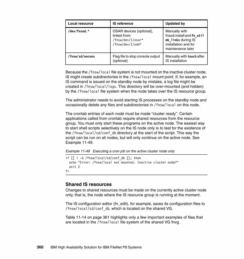
Because the /fnsw/local file system is not mounted on the inactive cluster node, IS might create subdirectories in the /fnsw/local mount point. If, for example, an IS command is issued on the standby node by mistake, a log file might be created in /fnsw/local/logs. This directory will be over-mounted (and hidden) by the /fnsw/local file system when the node takes over the IS resource group.
The administrator needs to avoid starting IS processes on the standby node and occasionally delete any files and subdirectories in /fnsw/local on this node.
The crontab entries of each node must be made “cluster ready”. Certain applications called from crontab require shared resources from the resource group. You must only start these programs on the active node. The easiest way to start shell scripts selectively on the IS node only is to test for the existence of the /fnsw/local/sd/conf_db directory at the start of the script. This way the script can be run on all nodes, but will only continue on the active node. See Example 11-49.
Example 11-49 Executing a cron job on the active cluster node only
if [[ ! -d /fnsw/local/sd/conf_db ]]; then echo "Error: /fnsw/local not mounted. Inactive cluster node?" exit 2fi
Shared IS resourcesChanges to shared resources must be made on the currently active cluster node only, that is, the node where the IS resource group is running at the moment.
The IS configuration editor (fn_edit), for example, saves its configuration files to /fnsw/local/sd/conf_db, which is located on the shared VG.
Table 11-14 on page 361 highlights only a few important examples of files that are located in the /fnsw/local file system of the shared VG fnvg.
/dev/fnsod.* OSAR devices {optional},linked from:/fnsw/dev/1/osar*/fnsw/dev/1/odd*
Manually with fnsod.install and fn_util mk_links during IS installation and for maintenance later
/fnsw/sd/nocons Flag file to stop console output {optional}
Manually with touch after IS installation
Local resource IS reference Updated by
360 IBM High Availability Solution for IBM FileNet P8 Systems
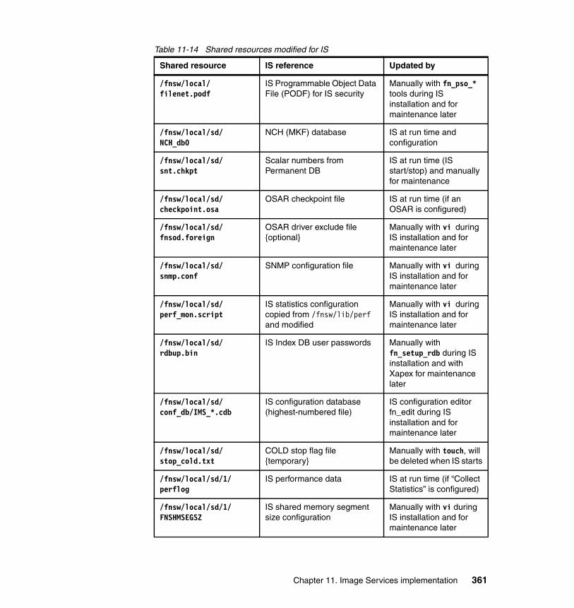
Table 11-14 Shared resources modified for IS
Shared resource IS reference Updated by
/fnsw/local/filenet.podf
IS Programmable Object Data File (PODF) for IS security
Manually with fn_pso_* tools during IS installation and for maintenance later
/fnsw/local/sd/NCH_db0
NCH (MKF) database IS at run time and configuration
/fnsw/local/sd/snt.chkpt
Scalar numbers from Permanent DB
IS at run time (IS start/stop) and manually for maintenance
/fnsw/local/sd/checkpoint.osa
OSAR checkpoint file IS at run time (if an OSAR is configured)
/fnsw/local/sd/fnsod.foreign
OSAR driver exclude file {optional}
Manually with vi during IS installation and for maintenance later
/fnsw/local/sd/snmp.conf
SNMP configuration file Manually with vi during IS installation and for maintenance later
/fnsw/local/sd/perf_mon.script
IS statistics configurationcopied from /fnsw/lib/perf and modified
Manually with vi during IS installation and for maintenance later
/fnsw/local/sd/rdbup.bin
IS Index DB user passwords Manually with fn_setup_rdb during IS installation and with Xapex for maintenance later
/fnsw/local/sd/conf_db/IMS_*.cdb
IS configuration database (highest-numbered file)
IS configuration editor fn_edit during IS installation and for maintenance later
/fnsw/local/sd/stop_cold.txt
COLD stop flag file {temporary}
Manually with touch, will be deleted when IS starts
/fnsw/local/sd/1/perflog
IS performance data IS at run time (if “Collect Statistics” is configured)
/fnsw/local/sd/1/FNSHMSEGSZ
IS shared memory segment size configuration
Manually with vi during IS installation and for maintenance later
Chapter 11. Image Services implementation 361

Most of the (optional and undocumented) flag files for IS or for IS patches or debug modules also reside on the shared file system. These files are examples:
� /fnsw/local/sd/cor_backoff_config� /fnsw/local/sd/no_build.txt� /fnsw/local/sd/1/cpu_bind� /fnsw/local/sd/1/bind_debug� /fnsw/local/sd/1/max_tli_elog� /fnsw/local/trigger/no_hint
HACMP File CollectionYou can automate the task of keeping local files in sync between cluster nodes by using the File Collection feature of HACMP. All files in the File Collection are automatically synchronized to the other node, when changed (by default, every 10 minutes). Use C-SPOC to configure a File Collection for IS:
# smitty hacmp
Click System Management (C-SPOC) → HACMP File Collection Management → Manage File Collections → Add a File Collection.
Enter these values:
� File Collection Name: filenet� Propagate files during cluster synchronization?: no� Propagate files automatically when changes are detected?: yes
/fnsw/local/sd/1/msar_identify_disable
Disable MSAR identify process {optional}
Manually with vi during IS installation
/fnsw/local/logs IS log files, for example, elogs, perf, EBR, or log
IS at run time and during installs or updates
/msar1 MSAR target directory IS at run time
/backup (EBR) backup target directory IS EBR backup/restore
/dev/rfn_*, for example:/dev/rfn_sec_*/dev/rfn_perm_*/dev/rfn_trans_*/dev/rfn_cache*
Raw devices for MKF DBs and cache, linked from:/fnsw/dev/1/sec_*/fnsw/dev/1/permanent_*/fnsw/dev/1/transient_*/fnsw/dev/1/cache*
IS at run time
Shared resource IS reference Updated by
362 IBM High Availability Solution for IBM FileNet P8 Systems
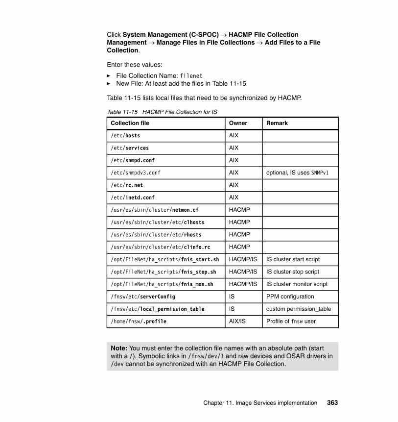
Click System Management (C-SPOC) → HACMP File Collection Management → Manage Files in File Collections → Add Files to a File Collection.
Enter these values:
� File Collection Name: filenet� New File: At least add the files in Table 11-15
Table 11-15 lists local files that need to be synchronized by HACMP.
Table 11-15 HACMP File Collection for IS
Collection file Owner Remark
/etc/hosts AIX
/etc/services AIX
/etc/snmpd.conf AIX
/etc/snmpdv3.conf AIX optional, IS uses SNMPv1
/etc/rc.net AIX
/etc/inetd.conf AIX
/usr/es/sbin/cluster/netmon.cf HACMP
/usr/es/sbin/cluster/etc/clhosts HACMP
/usr/es/sbin/cluster/etc/rhosts HACMP
/usr/es/sbin/cluster/etc/clinfo.rc HACMP
/opt/FileNet/ha_scripts/fnis_start.sh HACMP/IS IS cluster start script
/opt/FileNet/ha_scripts/fnis_stop.sh HACMP/IS IS cluster stop script
/opt/FileNet/ha_scripts/fnis_mon.sh HACMP/IS IS cluster monitor script
/fnsw/etc/serverConfig IS PPM configuration
/fnsw/etc/local_permission_table IS custom permission_table
/home/fnsw/.profile AIX/IS Profile of fnsw user
Note: You must enter the collection file names with an absolute path (start with a /). Symbolic links in /fnsw/dev/1 and raw devices and OSAR drivers in /dev cannot be synchronized with an HACMP File Collection.
Chapter 11. Image Services implementation 363
The HACMP configuration is stored in the local AIX Object Data Manager (ODM), but it is automatically copied to the other cluster node, when the HACMP Verification and Synchronization is run from SMIT (cldare):
# smitty hacmp
Click Extended Configuration → Extended Verification and Synchronization.
11.4.3 IS update procedures with HACMP
Patches for Image Services typically come in the form of service packs (SP) or fix packs (FP) that are packaged in an installation wizard. Problem Management Records (PMRs) sometimes produce individual fixes that consist of single files.
These minor release patches usually do not require you to update the Index database (DB2 or Oracle) or any of the MKF databases, but to simply replace binaries in /fnsw and /fnsw/local and perhaps run additional scripts.
IS major release updates usually require you to update the Index DB in advance, or they will update the database as part of the procedure. This action obviously has to be done only one time, during the update of the first node.
There is no rolling update with IS clusters. You must apply updates to all cluster nodes at the same time.
We recommend the following sequence to update IS in a cluster:
� Cluster node 1:
a. Suspend HACMP application monitoring for IS (smitty hacmp).
b. Disable the IS start script on both nodes by adding a line exit 0 on top.
c. Stop all IS clients, and clear ISTK shared memory (wal_purge).
d. Stop Image Services (initfnsw -y stop and killfnsw -ADSy),verify /fnsw/procs is empty, and end the remaining processes and purge /fnsw/procs.
e. Create a full backup of IS:
• AIX backup (bootable) of rootvg, for example, with mksysb(both nodes, optional for minor releases and single patches)
• Backup of Index DB (DB2) on the remote database server
• EBR backup of MKF DBs (Security/Permanent/Transient DB) and Cache
364 IBM High Availability Solution for IBM FileNet P8 Systems

• A savevg backup of fnvg or (at least) tar archive of /fnsw and /fnsw/local
f. Update the Index DB version of the (remote) server and the (local) client, if required.
g. Run the SP/FP installation wizard or copy a single patch to target directory.
h. Run fnsod.install, if the patch includes an updated /fnsw/bin/fnsod driver.
i. Verify or revert any changes to local resources:
• /fnsw/etc/serverConfig• /fnsw/etc/permission_table• /fnsw/lib/perf/reports• /fnsw/lib/perf/perf_mon.script• /fnsw/support/911• /etc/inittab {All IS-related entries in inittab must be disabled.}
j. Move IS resource group to node 2; IS must not start automatically.
� Cluster node 2:
a. Stop Image Services (initfnsw -y stop and killfnsw -ADSy). Just in case, verify that /fnsw/procs is empty, end the remaining processes, and purge /fnsw/procs.
b. Update the Index DB version of the (local) client, if required.
c. Run the SP/FP installation wizard, or copy a single patch to the target directory. If necessary, update any files in the /fnsw/local file system another time from node 2 of the cluster. If the wizard does not allow you to update IS another time “to the same level”, you can alternatively delete the local /fnsw part of the IS installation and all traces of previous updates (log files and ODM). Now, you can start a fresh installation on node 2, instead of an IS update. Remember not to run fn_edit or to initialize the databases on this cluster node.
d. Run fnsod.install, if the patch includes an updated /fnsw/bin/fnsod driver.
e. Verify or revert any changes to local resources:
• /fnsw/etc/serverConfig• /fnsw/etc/permission_table• /fnsw/lib/perf/reports• /fnsw/lib/perf/perf_mon.script• /fnsw/support/911• /etc/inittab {All IS-related entries in inittab must be disabled.}
f. Move the IS resource group to node 1; IS must not start automatically.
Chapter 11. Image Services implementation 365

g. Start IS manually with initfnsw start, and perform system and application tests.
h. Re-enable the IS start script on both nodes by removing exit 0 from line 1.
i. Resume HACMP application monitoring for IS (smitty hacmp).
j. Perform cluster tests, and move IS resource group to node 2, and then, to node 1.
k. Restart all IS clients, return to production mode.
Cluster and application tests are mandatory after every change to the IS installation or environment, such as AIX, HACMP, or DB2. Changes that affect the IS configuration (in the database) only might be transparent and require less effort.
11.4.4 Troubleshooting and log files
To troubleshoot problems in a highly available Image Services system, you must analyze both the IS error logs (elogs) and the cluster logs. To verify the status of a clustered IS, you must check both the cluster and IS.
Requesting status informationYou can check the current status of IS in an HACMP cluster with the clstat -ao (HACMP) and initfnsw status (IS) command.
HACMP statusThe most useful command for an overview of the cluster configuration is the # /usr/es/sbin/cluster/utilities/cldisp command.
You can verify the current status of the cluster with the # /usr/es/sbin/cluster/clstat -ao command.
The clstat command shows if nodes and interfaces are up or down and if the IS resource group is online and on which node (for example, fnl43). The Cluster Information Daemon (clinfoES) must be running for clstat to work. See Example 11-50.
Example 11-50 Running clstat for the current cluster status
# cd /usr/es/sbin/cluster# clstat -ao
clstat - HACMP Cluster Status Monitor -------------------------------------
366 IBM High Availability Solution for IBM FileNet P8 Systems

Cluster: fnis (1222565798)Sun Nov 9 20:41:40 PST 2008 State: UP Nodes: 2 SubState: STABLE
Node: fnl43 State: UP Interface: fnl43-bt1 (2) Address: 10.10.10.53 State: UP Interface: fnl43_vpath0_01 (0) Address: 0.0.0.0 State: UP Interface: fnis (2) Address: 9.30.188.78 State: UP Interface: fnl43-hs03 (1) Address: 10.0.3.53 State: UP Resource Group: fnis_rg State: On line
Node: fnl44 State: UP Interface: fnl44-bt1 (2) Address: 10.10.10.54 State: UP Interface: fnl44_vpath0_01 (0) Address: 0.0.0.0 State: UP Interface: fnl44-hs03 (1) Address: 10.0.3.54 State: UP
Image Services statusYou can view the status of IS with the # /fnsw/bin/initfnsw status command.
Because the initfnsw command does not always correctly report if IS is actually working (or if it is stopped or inaccessible by clients), we recommend that you also look at the IS error log by using this command: # /fnsw/bin/vl.
Log files for troubleshootingTable 11-16 on page 368 lists the log files that can be consulted in the case of HA-related problems with IS.
Chapter 11. Image Services implementation 367
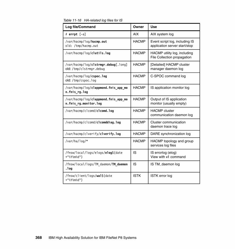
Table 11-16 HA-related log files for IS
Log file/Command Owner Use
# errpt [-a] AIX AIX system log
/var/hacmp/log/hacmp.outold: /tmp/hacmp.out
HACMP Event script log, including IS application server start/stop
/var/hacmp/log/clutils.log HACMP HACMP utility log, including File Collection propagation
/var/hacmp/log/clstrmgr.debug[.long]old: /tmp/clstrmgr.debug
HACMP [Detailed] HACMP cluster manager daemon log
/var/hacmp/log/cspoc.logold: /tmp/cspoc.log
HACMP C-SPOC command log
/var/hacmp/log/clappmond.fnis_app_mon.fnis_rg.log
HACMP IS application monitor log
/var/hacmp/log/clappmond.fnis_app_mon.fnis_rg.monitor.log
HACMP Output of IS application monitor (usually empty)
/var/hacmp/clcomd/clcomd.log HACMP HACMP cluster communication daemon log
/var/hacmp/clcomd/clcomddiag.log HACMP Cluster communication daemon trace log
/var/hacmp/clverify/clverify.log HACMP DARE synchronization log
/var/ha/log/* HACMP HACMP topology and group services log files
/fnsw/local/logs/elogs/elog$(date +"%Y%m%d")
IS IS errorlog (elog)View with vl command
/fnsw/local/logs/TM_daemon/TM_daemon.log
IS IS TM_daemon log
/fnsw/client/logs/wal$(date +"%Y%m%d")
ISTK ISTK error log
368 IBM High Availability Solution for IBM FileNet P8 Systems

Chapter 12. DB2 implementation
Content Engine and Process Engine have their own databases. In addition, Image Services also has its own database. To ensure the high availability of an IBM FileNet P8 solution, we must ensure that the database component is also highly available.
This chapter describes the following topics:
� DB2 high availability strategies for FileNet P8� Setting up DB2 high availability for FileNet P8� High availability tests for DB2� Maintenance and upgrade recommendations for DB2
12
© Copyright IBM Corp. 2009. All rights reserved. 369
12.1 DB2 high availability strategies for FileNet P8
This section provides an overview of DB2 high availability (HA) strategies for FileNet P8. For a FileNet environment, the database server is a key functional component. The Content Engine (CE), the Process Engine (PE), and Image Services (IS) use the database server for storing data.
The DB2 high availability scenario for a FileNet environment that we consider in this section is based on an active/passive cluster. In a scenario of two nodes, only one DB2 server is available for client access. The second DB2 server is not active, because it is a hot standby server. It is activated only when the primary node fails.
The DB2 9.5 High Availability (HA) feature supports the IBM Data Server with cluster management software, such as IBM PowerHA for AIX, formerly IBM High Availability Cluster Multi-Processing (HACMP), IBM Tivoli System Automation for Multiplatforms, and Microsoft Windows Server® Cluster. In DB2 9.5, IBM Tivoli System Automation for Multiplatforms Base Component is integrated with IBM Data Server on AIX and Linux as part of the DB2 High Availability feature. When you install DB2 9.5 on AIX or Linux, you have the option to install this feature, which automatically installs IBM Tivoli System Automation for Multiplatforms. The DB2 High Availability Configuration Utility (db2haicu) provided by DB2 for configuring DB2 with IBM Tivoli System Automation for Multiplatforms greatly simplifies the clustering configuration.
The DB2 High Availability feature enables the database manager to automatically request cluster manager configuration changes whenever you perform certain database manager instance configuration and administration operations. The DB2 cluster manager API defines a set of functions that enables the database manager to communicate configuration changes to the cluster manager.
The DB2 Data Server High Availability and Disaster Recovery (HADR) feature provides data replication, which can be used (together with clustering software, such as IBM Tivoli System Automation for Multiplatforms or HACMP) to provide high availability. HADR protects against data loss by replicating data changes from a source database, called the primary, to a target database, called the standby.
For more details about DB2 HA strategies, refer to High Availability, Scalability, and Disaster Recovery for DB2 on Linux, UNIX, and Windows, SG24-7363.
370 IBM High Availability Solution for IBM FileNet P8 Systems

12.1.1 Database considerations for FileNet P8
The following FileNet components use the database layer for their functionality:
� Content Engine (CE):
CE is the major component of the FileNet P8 application, and it requires two repositories: Global Configuration Database (GCD), which stores global system configuration information for all servers in the IBM FileNet P8 domain, and the object store, which stores the objects in an IBM FileNet P8 environment. There can be one or multiple object stores. Each object store manages a database (CE database) for metadata. Each object store can have one or more storage areas that represent the physical storage area location.
� Process Engine (PE):
PE uses a database for storing all process-related data.
� Image Services (IS):
IS uses a database to store metadata for the documents that are archived in IS, such as document classes and document properties, called indexes. During normal operations, the index database updates are synchronized with the permanent database, which is called Multi-Keyed File (MFK), in IS that stores the storage locations of the documents.
In a DB2 environment, databases can share an instance or can have a dedicated instance for each database. The IBM FileNet P8 components can be configured in both shared and dedicated configurations. When choosing the database configuration, you might take into consideration a few factors: the estimated size and load of the databases, the requirements of the CE, PE, and IS components, as well as maintenance and backup of the databases. Refer to the requirements of each component for the version you are installing.
In a larger environment, consider using separate systems for each FileNet component’s databases.
Note: The file storage areas for Content Engine must be deployed on highly available storage that has built-in redundancy for all components. Refer to your storage vendor for details.
Chapter 12. DB2 implementation 371
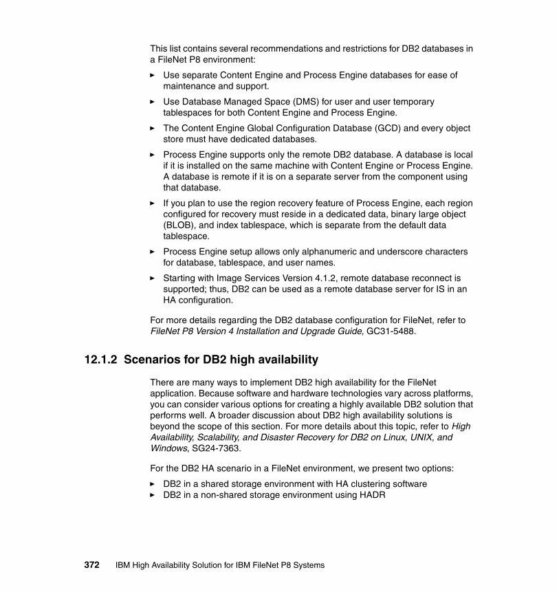
This list contains several recommendations and restrictions for DB2 databases in a FileNet P8 environment:
� Use separate Content Engine and Process Engine databases for ease of maintenance and support.
� Use Database Managed Space (DMS) for user and user temporary tablespaces for both Content Engine and Process Engine.
� The Content Engine Global Configuration Database (GCD) and every object store must have dedicated databases.
� Process Engine supports only the remote DB2 database. A database is local if it is installed on the same machine with Content Engine or Process Engine. A database is remote if it is on a separate server from the component using that database.
� If you plan to use the region recovery feature of Process Engine, each region configured for recovery must reside in a dedicated data, binary large object (BLOB), and index tablespace, which is separate from the default data tablespace.
� Process Engine setup allows only alphanumeric and underscore characters for database, tablespace, and user names.
� Starting with Image Services Version 4.1.2, remote database reconnect is supported; thus, DB2 can be used as a remote database server for IS in an HA configuration.
For more details regarding the DB2 database configuration for FileNet, refer to FileNet P8 Version 4 Installation and Upgrade Guide, GC31-5488.
12.1.2 Scenarios for DB2 high availability
There are many ways to implement DB2 high availability for the FileNet application. Because software and hardware technologies vary across platforms, you can consider various options for creating a highly available DB2 solution that performs well. A broader discussion about DB2 high availability solutions is beyond the scope of this section. For more details about this topic, refer to High Availability, Scalability, and Disaster Recovery for DB2 on Linux, UNIX, and Windows, SG24-7363.
For the DB2 HA scenario in a FileNet environment, we present two options:
� DB2 in a shared storage environment with HA clustering software� DB2 in a non-shared storage environment using HADR
372 IBM High Availability Solution for IBM FileNet P8 Systems
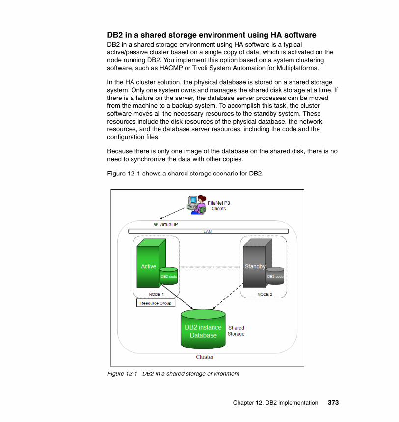
DB2 in a shared storage environment using HA softwareDB2 in a shared storage environment using HA software is a typical active/passive cluster based on a single copy of data, which is activated on the node running DB2. You implement this option based on a system clustering software, such as HACMP or Tivoli System Automation for Multiplatforms.
In the HA cluster solution, the physical database is stored on a shared storage system. Only one system owns and manages the shared disk storage at a time. If there is a failure on the server, the database server processes can be moved from the machine to a backup system. To accomplish this task, the cluster software moves all the necessary resources to the standby system. These resources include the disk resources of the physical database, the network resources, and the database server resources, including the code and the configuration files.
Because there is only one image of the database on the shared disk, there is no need to synchronize the data with other copies.
Figure 12-1 shows a shared storage scenario for DB2.
Figure 12-1 DB2 in a shared storage environment
Chapter 12. DB2 implementation 373
You have to consider a few aspects regarding the cluster resources for the DB2 database:
� Storage resource: It refers to the disks, raw devices, or file systems that are used by DB2 to hold the database environment, which consists of these components:
– DB2 code: It is the location where DB2 software is installed. Typically, it is located on the local disks of each node. For DB2 Version 8, the code is installed in a predefined location. Staring from DB2 Version 9, you can define the location for the DB2 installation.
– Database instance: The database files for an instance are common to all nodes of the cluster; thus, they need to be placed on the shared storage.
� Network resource: A virtual IP address resource can be used for the client access to the database. In case of a failure, the IP address is activated on the standby node, so the clients do not need to change their connection configuration. For an environment using multiple DB2 instances, you can use multiple virtual IP addresses.
� Database server resource: It usually consists of scripts to start, stop, and monitor the instance and database. The cluster software uses these scripts to monitor the database environment and transparently fail the active node over to the standby node in case the active node fails.
When a failure is detected, ownership of the storage is moved from the primary system to the standby system. The network resources are moved, as well. Finally, the database server resources are started on the standby node and the database is made available as shown in Figure 12-2 on page 375.
374 IBM High Availability Solution for IBM FileNet P8 Systems

Figure 12-2 DB2 failure in a shared storage scenario
After a failover, DB2 always performs crash recovery, because the database was not shut down properly. During the crash recovery, the database engine processes the log files, making sure that all committed transactions are written to the disk and that the uncommitted transactions are rolled back. The time that is required to perform this operation depends on the amount of open work in the database logs at the point of failure. The failover process duration can vary, depending on the number of transactions that need to be processed from the logs.
When a failure occurs on the primary system, all applications are disconnected, and a communication error is returned to the application. When the database becomes available on the standby system, the application simply needs to reconnect to the database, and then, it can continue to work as before. The DB2 automatic client reroute (ACR) feature can be used to automatically route or reconnect the client connection to the active database instance. With the ACR, DB2 will route application connections to the failover server, and there is no need for the applications to reconnect. The ACR function is supported by DB2 Version 8.2 and later.
Chapter 12. DB2 implementation 375
In a basic, two-node hot-standby configuration, the resources of the two nodes do not need to be identical. Because the standby node is used only in failover or maintenance cases, it can be configured with less CPU and memory.
The basic hot-standby scenario can be extended to a mutual takeover configuration where both servers are actively hosting separate databases. Each machine is prepared to take over the workload of its peer node in the event of a failure.
Table 12-1 summarizes the advantages and disadvantages of a shared disk environment in an HA environment, compared with other HA solution options, including options that we do not discuss in this book. For more details, refer to Implementing high availability with DB2 9.5 at this Web site:
http://www.ibm.com/developerworks/db2/library/techarticle/dm-0807wright/
Table 12-1 Shared storage advantages and disadvantages
DB2 in a non-shared storage system with HADRThis scenario is based on the DB2 High Availability Disaster Recovery (HADR) feature. The DB2 HADR is a high performance database replication system that is based on the DB2 logging mechanism. An HADR scenario consists of two independent systems, a primary and a standby. The primary system serves the client connections, performs the transactional work, and replicates the database changes to the standby system. In a HADR configuration, each node runs its own DB2 instance and database on its own storage. See Figure 12-3 on page 377.
Note: In an environment that supports partitioning, such as System p, the resources of logical partitions can be dynamically changed at the failover time with or without the assistance of the clustering software.
Advantages Disadvantages
� Database copies are always consistent.
� No changes to the application or to the client are needed.
� No user interaction is needed to detect and initialize failover.
� There is no performance degradation due to HA solution design.
� Extra software is needed to create and configure the solution.
� Data is not duplicated, providing less redundancy.
� External storage is required that must meet certain HA standards.
� There are distance limitations due to storage requirements.
376 IBM High Availability Solution for IBM FileNet P8 Systems
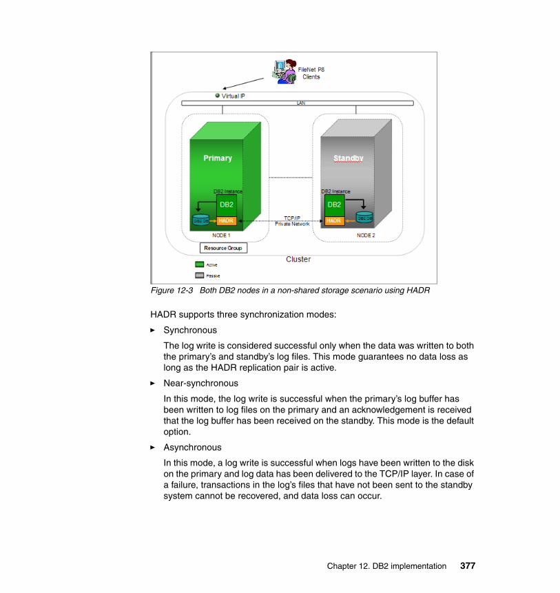
Figure 12-3 Both DB2 nodes in a non-shared storage scenario using HADR
HADR supports three synchronization modes:
� Synchronous
The log write is considered successful only when the data was written to both the primary’s and standby’s log files. This mode guarantees no data loss as long as the HADR replication pair is active.
� Near-synchronous
In this mode, the log write is successful when the primary’s log buffer has been written to log files on the primary and an acknowledgement is received that the log buffer has been received on the standby. This mode is the default option.
� Asynchronous
In this mode, a log write is successful when logs have been written to the disk on the primary and log data has been delivered to the TCP/IP layer. In case of a failure, transactions in the log’s files that have not been sent to the standby system cannot be recovered, and data loss can occur.
Chapter 12. DB2 implementation 377
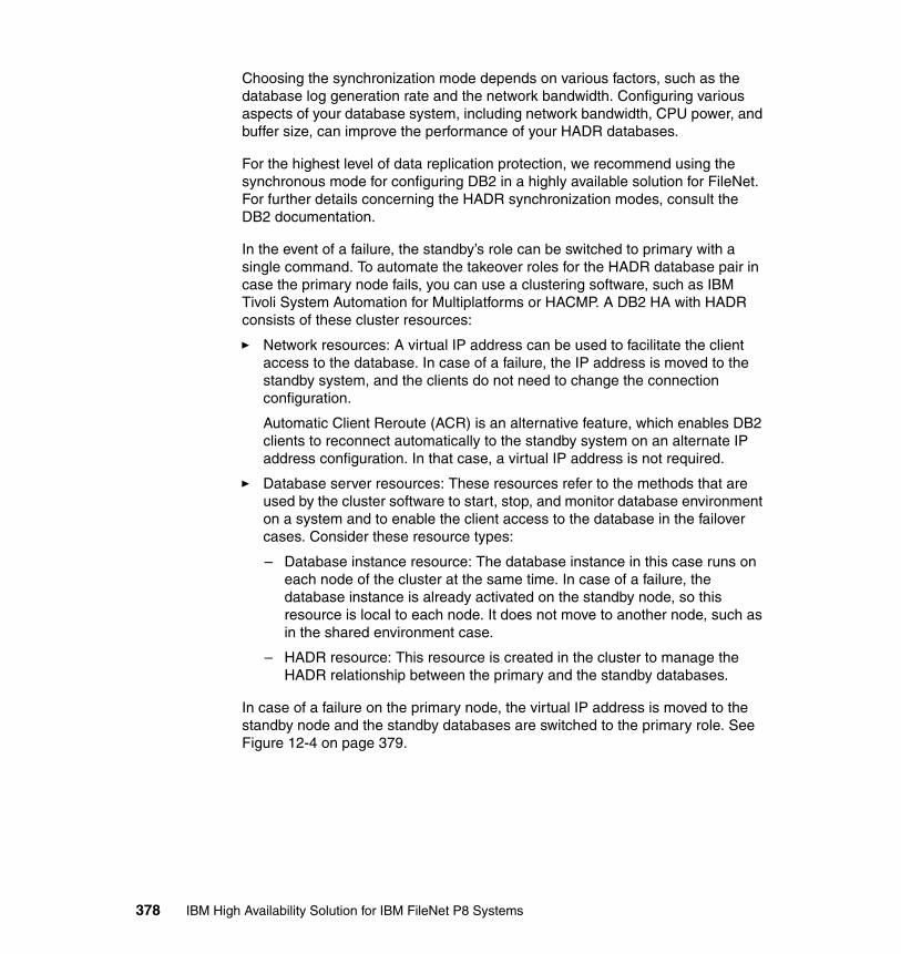
Choosing the synchronization mode depends on various factors, such as the database log generation rate and the network bandwidth. Configuring various aspects of your database system, including network bandwidth, CPU power, and buffer size, can improve the performance of your HADR databases.
For the highest level of data replication protection, we recommend using the synchronous mode for configuring DB2 in a highly available solution for FileNet. For further details concerning the HADR synchronization modes, consult the DB2 documentation.
In the event of a failure, the standby’s role can be switched to primary with a single command. To automate the takeover roles for the HADR database pair in case the primary node fails, you can use a clustering software, such as IBM Tivoli System Automation for Multiplatforms or HACMP. A DB2 HA with HADR consists of these cluster resources:
� Network resources: A virtual IP address can be used to facilitate the client access to the database. In case of a failure, the IP address is moved to the standby system, and the clients do not need to change the connection configuration.
Automatic Client Reroute (ACR) is an alternative feature, which enables DB2 clients to reconnect automatically to the standby system on an alternate IP address configuration. In that case, a virtual IP address is not required.
� Database server resources: These resources refer to the methods that are used by the cluster software to start, stop, and monitor database environment on a system and to enable the client access to the database in the failover cases. Consider these resource types:
– Database instance resource: The database instance in this case runs on each node of the cluster at the same time. In case of a failure, the database instance is already activated on the standby node, so this resource is local to each node. It does not move to another node, such as in the shared environment case.
– HADR resource: This resource is created in the cluster to manage the HADR relationship between the primary and the standby databases.
In case of a failure on the primary node, the virtual IP address is moved to the standby node and the standby databases are switched to the primary role. See Figure 12-4 on page 379.
378 IBM High Availability Solution for IBM FileNet P8 Systems
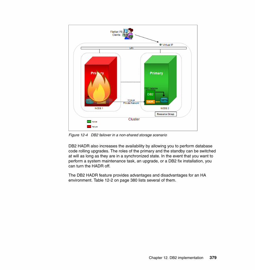
Figure 12-4 DB2 failover in a non-shared storage scenario
DB2 HADR also increases the availability by allowing you to perform database code rolling upgrades. The roles of the primary and the standby can be switched at will as long as they are in a synchronized state. In the event that you want to perform a system maintenance task, an upgrade, or a DB2 fix installation, you can turn the HADR off.
The DB2 HADR feature provides advantages and disadvantages for an HA environment. Table 12-2 on page 380 lists several of them.
Chapter 12. DB2 implementation 379
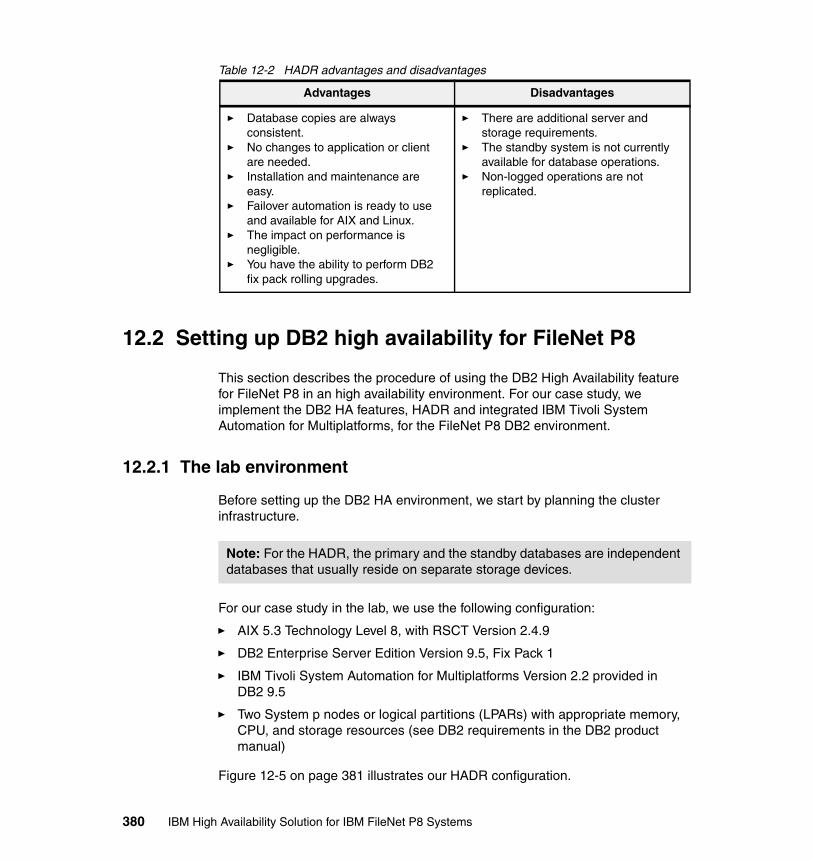
Table 12-2 HADR advantages and disadvantages
12.2 Setting up DB2 high availability for FileNet P8
This section describes the procedure of using the DB2 High Availability feature for FileNet P8 in an high availability environment. For our case study, we implement the DB2 HA features, HADR and integrated IBM Tivoli System Automation for Multiplatforms, for the FileNet P8 DB2 environment.
12.2.1 The lab environment
Before setting up the DB2 HA environment, we start by planning the cluster infrastructure.
For our case study in the lab, we use the following configuration:
� AIX 5.3 Technology Level 8, with RSCT Version 2.4.9
� DB2 Enterprise Server Edition Version 9.5, Fix Pack 1
� IBM Tivoli System Automation for Multiplatforms Version 2.2 provided in DB2 9.5
� Two System p nodes or logical partitions (LPARs) with appropriate memory, CPU, and storage resources (see DB2 requirements in the DB2 product manual)
Figure 12-5 on page 381 illustrates our HADR configuration.
Advantages Disadvantages
� Database copies are always consistent.
� No changes to application or client are needed.
� Installation and maintenance are easy.
� Failover automation is ready to use and available for AIX and Linux.
� The impact on performance is negligible.
� You have the ability to perform DB2 fix pack rolling upgrades.
� There are additional server and storage requirements.
� The standby system is not currently available for database operations.
� Non-logged operations are not replicated.
Note: For the HADR, the primary and the standby databases are independent databases that usually reside on separate storage devices.
380 IBM High Availability Solution for IBM FileNet P8 Systems
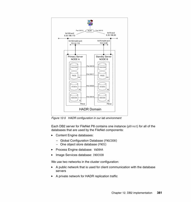
Figure 12-5 HADR configuration in our lab environment
Each DB2 server for FileNet P8 contains one instance (p8inst) for all of the databases that are used by the FileNet components:
� Content Engine databases:
– Global Configuration Database (FNGCDDB)– One object store database (FNOS)
� Process Engine database: VWDBHA
� Image Services database: INDEXDB
We use two networks in the cluster configuration:
� A public network that is used for client communication with the database servers
� A private network for HADR replication traffic
fnl100-hs04:en310.0.4.110
fnl100:en29.30.188.110
fnl70:en29.30.188.80
fnl70-hs04:en310.0.4.80
Primary ServerNODE A
ACR
FNGCDDB
FNOS
VWDBHA
INDEXDB
CE
PE
IS
P8inst
HADR Domain
Standby ServerNODE B
FNGCDDB
FNOS
VWDBHA
INDEXDB
CE
PE
IS
P8inst
Port 50018
Port 50017
Port 50020
Port 50016
Port 50010Port 50010
Chapter 12. DB2 implementation 381

Table 12-3 shows the host names and the IP addresses for the public and private interfaces on each node.
Table 12-3 Host name and IP addresses
HADR data replication feature works at the database level. For each database pair that is involved in an HADR relationship, a pair of TCP/IP ports is required for communication. In our case study, we use the same port number on both servers. Each port number has an associated service name in the /etc/services file. Table 12-4 describes the TCP/IP port configuration for HADR communication.
Table 12-4 HADR ports and service names for FileNet DB2 databases
In an HADR pair, one system is the primary system (fnl100) that holds the active databases currently accessed by the clients for their database operations. The other system is the standby system (fnl70) and has a passive role. Each database has a standby copy on the standby system. To replicate, for each database pair, we have set the HADR synchronization mode (HADR_SYNCMODE) to SYNC.
Each DB2 server has a TCP/IP port number to communicate with the clients. In our case study, we use 50010 for both nodes. You might also consider using separate ports, because DB2 instances on primary and standby nodes work independently of each other.
We use the ACR feature on the DB2 server to enable automatic recovery for the client connection in case of primary server failure. A Virtual IP address is not a requirement when using the ACR feature and is not used in our environment.
Host name HADR role Interface: Public IP Interface: Private IP
fnl100 Primary en2:9.30.188.110 en3:10.0.4.110
fnl70 Standby en0:9.30.188.80 en3:10.0.4.80
FileNet component Database name Service name Port number
Image Services INDEXDB p8_INDEX 50016
Content Engine FNOS p8_FNOS 50017
Content Engine FNGCDDB p8_GCD 50018
Process Engine VWDBHA p8_VWDBHA 50020
382 IBM High Availability Solution for IBM FileNet P8 Systems
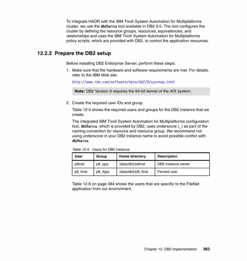
To integrate HADR with the IBM Tivoli System Automation for Multiplatforms cluster, we use the db2haicu tool available in DB2 9.5. The tool configures the cluster by defining the resource groups, resources, equivalencies, and relationships and uses the IBM Tivoli System Automation for Multiplatforms policy scripts, which are provided with DB2, to control the application resources.
12.2.2 Prepare the DB2 setup
Before installing DB2 Enterprise Server, perform these steps:
1. Make sure that the hardware and software requirements are met. For details, refer to the IBM Web site:
http://www.ibm.com/software/data/db2/9/sysreqs.html
2. Create the required user IDs and group.
Table 12-5 shows the required users and groups for the DB2 instance that we create.
The integrated IBM Tivoli System Automation for Multiplatforms configuration tool, db2haicu, which is provided by DB2, uses underscore (_) as part of the naming convention for resource and resource group. We recommend not using underscore in your DB2 instance name to avoid possible conflict with db2haicu.
Table 12-5 Users for DB2 instance
Table 12-6 on page 384 shows the users that are specific to the FileNet application from our environment.
Note: DB2 Version 9 requires the 64-bit kernel of the AIX system.
User Group Home directory Description
p8inst p8_igrp /data/db2/p8inst DB2 instance owner
p8_finst p8_ifgrp /data/db2/p8_finst Fenced user
Chapter 12. DB2 implementation 383
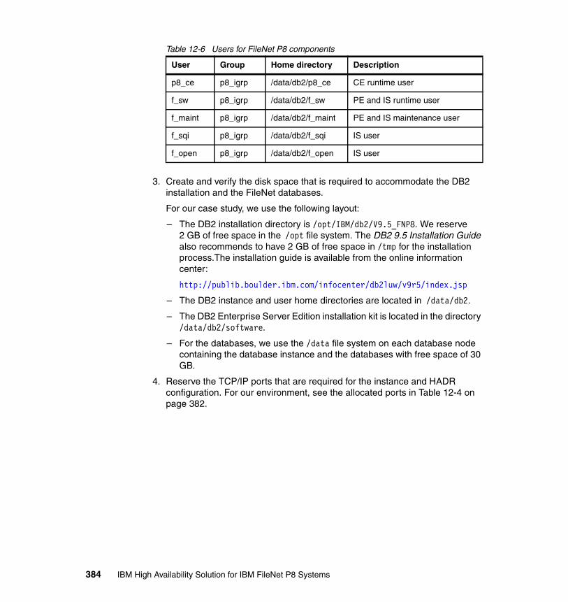
Table 12-6 Users for FileNet P8 components
3. Create and verify the disk space that is required to accommodate the DB2 installation and the FileNet databases.
For our case study, we use the following layout:
– The DB2 installation directory is /opt/IBM/db2/V9.5_FNP8. We reserve 2 GB of free space in the /opt file system. The DB2 9.5 Installation Guide also recommends to have 2 GB of free space in /tmp for the installation process.The installation guide is available from the online information center:
http://publib.boulder.ibm.com/infocenter/db2luw/v9r5/index.jsp
– The DB2 instance and user home directories are located in /data/db2.
– The DB2 Enterprise Server Edition installation kit is located in the directory /data/db2/software.
– For the databases, we use the /data file system on each database node containing the database instance and the databases with free space of 30 GB.
4. Reserve the TCP/IP ports that are required for the instance and HADR configuration. For our environment, see the allocated ports in Table 12-4 on page 382.
User Group Home directory Description
p8_ce p8_igrp /data/db2/p8_ce CE runtime user
f_sw p8_igrp /data/db2/f_sw PE and IS runtime user
f_maint p8_igrp /data/db2/f_maint PE and IS maintenance user
f_sqi p8_igrp /data/db2/f_sqi IS user
f_open p8_igrp /data/db2/f_open IS user
384 IBM High Availability Solution for IBM FileNet P8 Systems
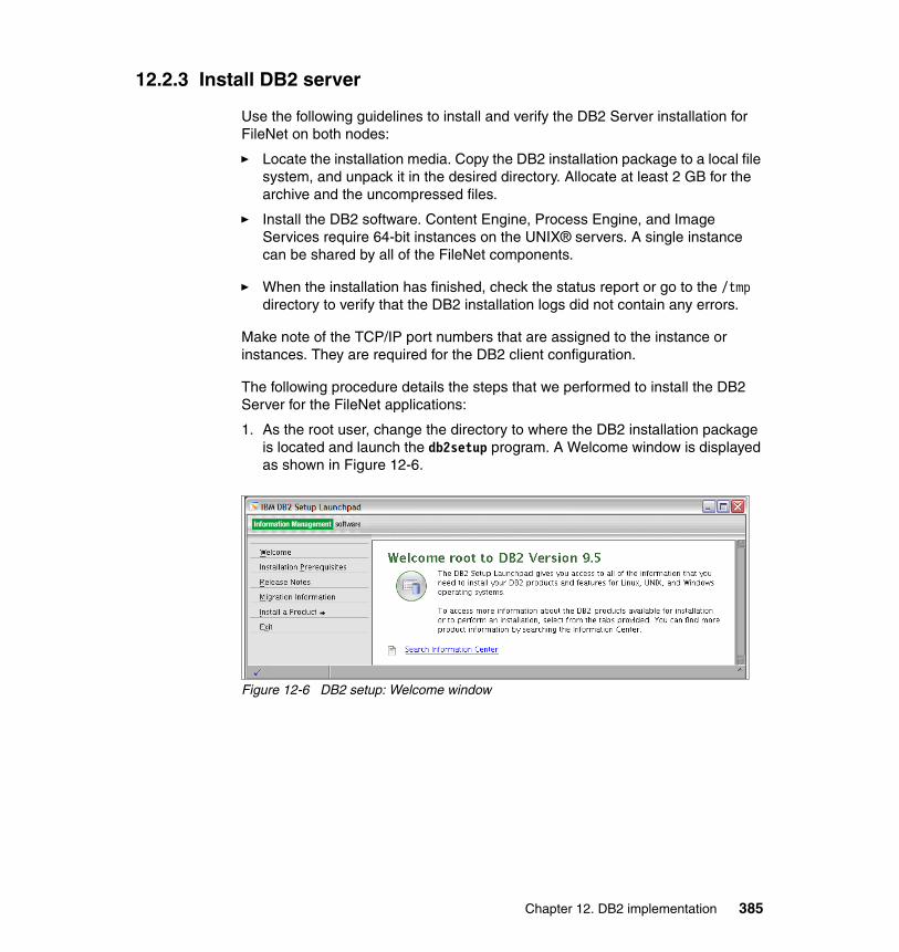
12.2.3 Install DB2 server
Use the following guidelines to install and verify the DB2 Server installation for FileNet on both nodes:
� Locate the installation media. Copy the DB2 installation package to a local file system, and unpack it in the desired directory. Allocate at least 2 GB for the archive and the uncompressed files.
� Install the DB2 software. Content Engine, Process Engine, and Image Services require 64-bit instances on the UNIX® servers. A single instance can be shared by all of the FileNet components.
� When the installation has finished, check the status report or go to the /tmp directory to verify that the DB2 installation logs did not contain any errors.
Make note of the TCP/IP port numbers that are assigned to the instance or instances. They are required for the DB2 client configuration.
The following procedure details the steps that we performed to install the DB2 Server for the FileNet applications:
1. As the root user, change the directory to where the DB2 installation package is located and launch the db2setup program. A Welcome window is displayed as shown in Figure 12-6.
Figure 12-6 DB2 setup: Welcome window
Chapter 12. DB2 implementation 385

2. Select Install a product, and then select Installing DB2 Enterprise Server Edition Version 9.5. The DB2 setup window is launched. See Figure 12-7.
Figure 12-7 DB2 setup menu
386 IBM High Availability Solution for IBM FileNet P8 Systems
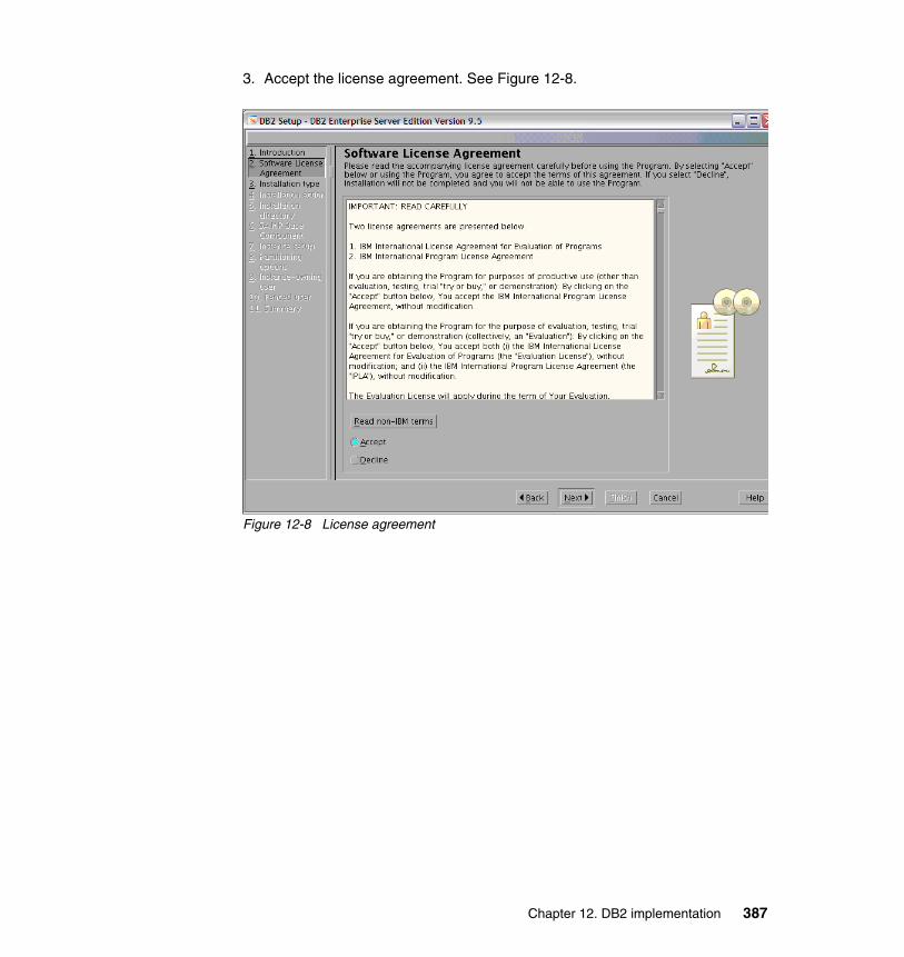
3. Accept the license agreement. See Figure 12-8.
Figure 12-8 License agreement
Chapter 12. DB2 implementation 387
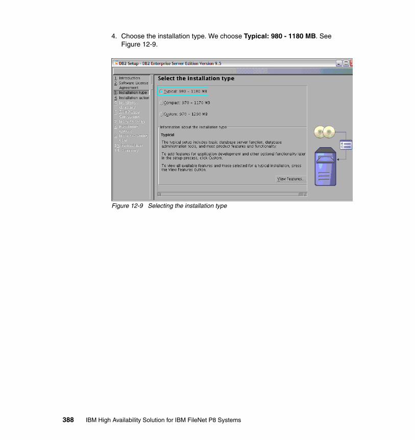
4. Choose the installation type. We choose Typical: 980 - 1180 MB. See Figure 12-9.
Figure 12-9 Selecting the installation type
388 IBM High Availability Solution for IBM FileNet P8 Systems
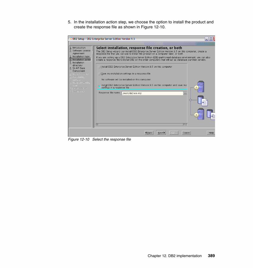
5. In the installation action step, we choose the option to install the product and create the response file as shown in Figure 12-10.
Figure 12-10 Select the response file
Chapter 12. DB2 implementation 389
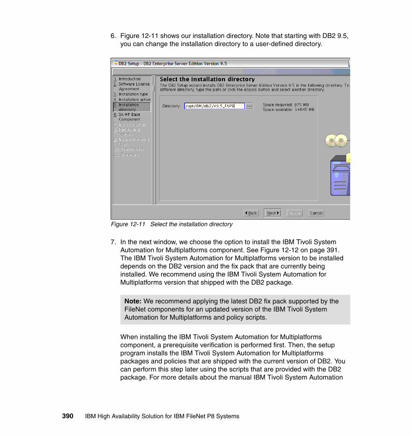
6. Figure 12-11 shows our installation directory. Note that starting with DB2 9.5, you can change the installation directory to a user-defined directory.
Figure 12-11 Select the installation directory
7. In the next window, we choose the option to install the IBM Tivoli System Automation for Multiplatforms component. See Figure 12-12 on page 391. The IBM Tivoli System Automation for Multiplatforms version to be installed depends on the DB2 version and the fix pack that are currently being installed. We recommend using the IBM Tivoli System Automation for Multiplatforms version that shipped with the DB2 package.
When installing the IBM Tivoli System Automation for Multiplatforms component, a prerequisite verification is performed first. Then, the setup program installs the IBM Tivoli System Automation for Multiplatforms packages and policies that are shipped with the current version of DB2. You can perform this step later using the scripts that are provided with the DB2 package. For more details about the manual IBM Tivoli System Automation
Note: We recommend applying the latest DB2 fix pack supported by the FileNet components for an updated version of the IBM Tivoli System Automation for Multiplatforms and policy scripts.
390 IBM High Availability Solution for IBM FileNet P8 Systems
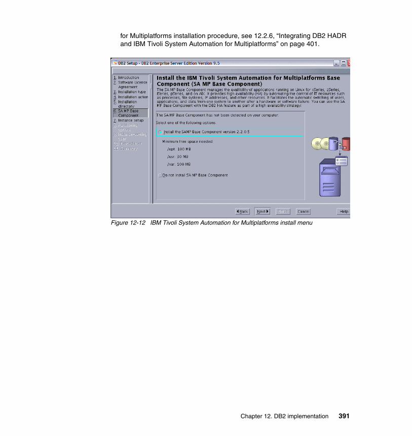
for Multiplatforms installation procedure, see 12.2.6, “Integrating DB2 HADR and IBM Tivoli System Automation for Multiplatforms” on page 401.
Figure 12-12 IBM Tivoli System Automation for Multiplatforms install menu
Chapter 12. DB2 implementation 391

8. In the instance setup step (Figure 12-13), we choose not to create the instance, because we create the instance in a later step.
Figure 12-13 Instance creation
392 IBM High Availability Solution for IBM FileNet P8 Systems
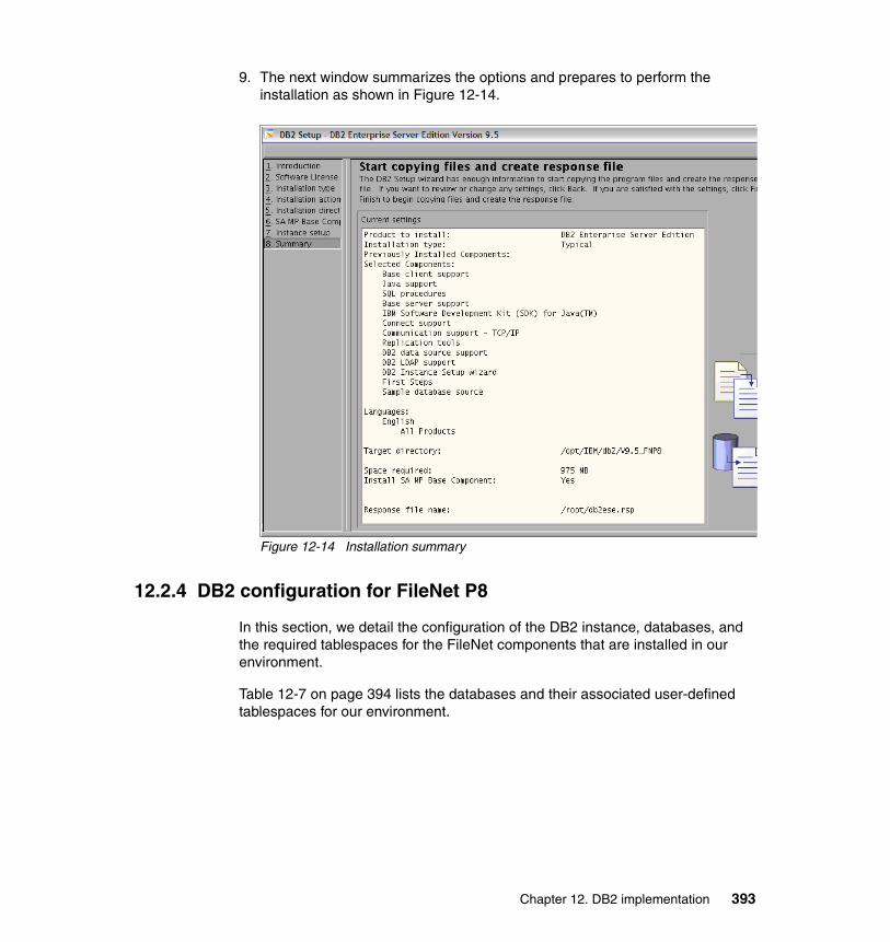
9. The next window summarizes the options and prepares to perform the installation as shown in Figure 12-14.
Figure 12-14 Installation summary
12.2.4 DB2 configuration for FileNet P8
In this section, we detail the configuration of the DB2 instance, databases, and the required tablespaces for the FileNet components that are installed in our environment.
Table 12-7 on page 394 lists the databases and their associated user-defined tablespaces for our environment.
Chapter 12. DB2 implementation 393
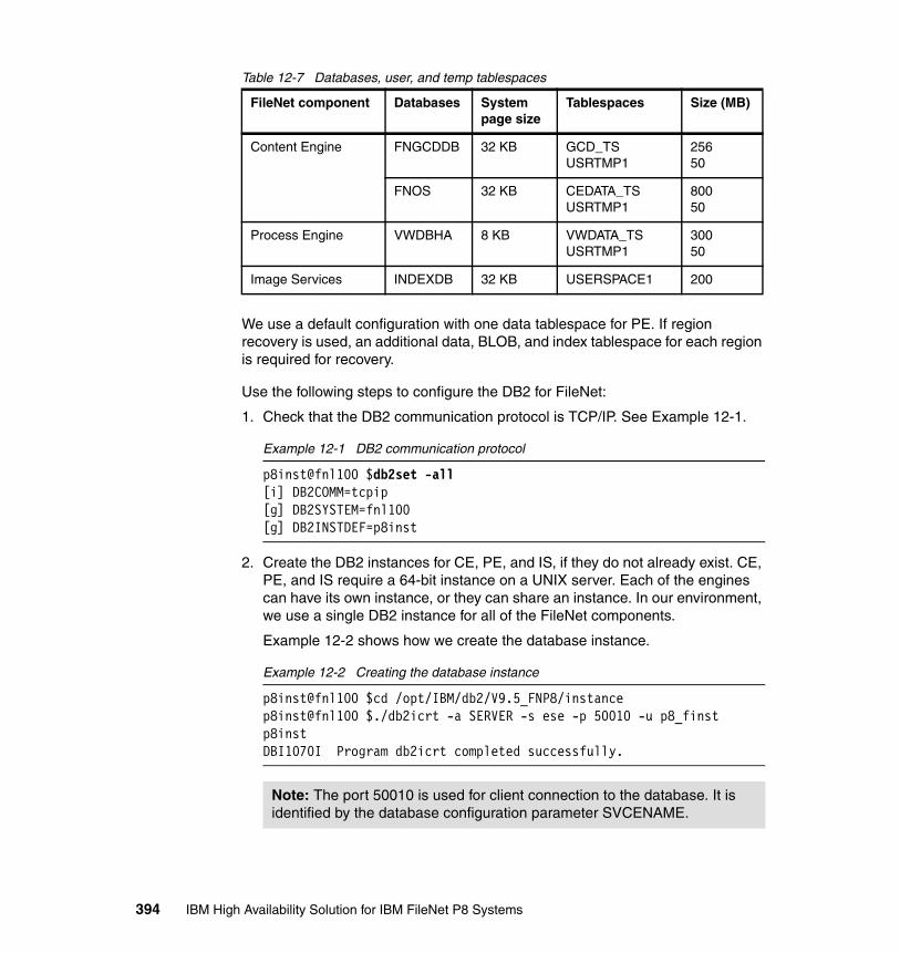
Table 12-7 Databases, user, and temp tablespaces
We use a default configuration with one data tablespace for PE. If region recovery is used, an additional data, BLOB, and index tablespace for each region is required for recovery.
Use the following steps to configure the DB2 for FileNet:
1. Check that the DB2 communication protocol is TCP/IP. See Example 12-1.
Example 12-1 DB2 communication protocol
p8inst@fnl100 $db2set -all[i] DB2COMM=tcpip[g] DB2SYSTEM=fnl100[g] DB2INSTDEF=p8inst
2. Create the DB2 instances for CE, PE, and IS, if they do not already exist. CE, PE, and IS require a 64-bit instance on a UNIX server. Each of the engines can have its own instance, or they can share an instance. In our environment, we use a single DB2 instance for all of the FileNet components.
Example 12-2 shows how we create the database instance.
Example 12-2 Creating the database instance
p8inst@fnl100 $cd /opt/IBM/db2/V9.5_FNP8/instancep8inst@fnl100 $./db2icrt -a SERVER -s ese -p 50010 -u p8_finst p8instDBI1070I Program db2icrt completed successfully.
FileNet component Databases System page size
Tablespaces Size (MB)
Content Engine FNGCDDB 32 KB GCD_TSUSRTMP1
25650
FNOS 32 KB CEDATA_TSUSRTMP1
80050
Process Engine VWDBHA 8 KB VWDATA_TSUSRTMP1
30050
Image Services INDEXDB 32 KB USERSPACE1 200
Note: The port 50010 is used for client connection to the database. It is identified by the database configuration parameter SVCENAME.
394 IBM High Availability Solution for IBM FileNet P8 Systems
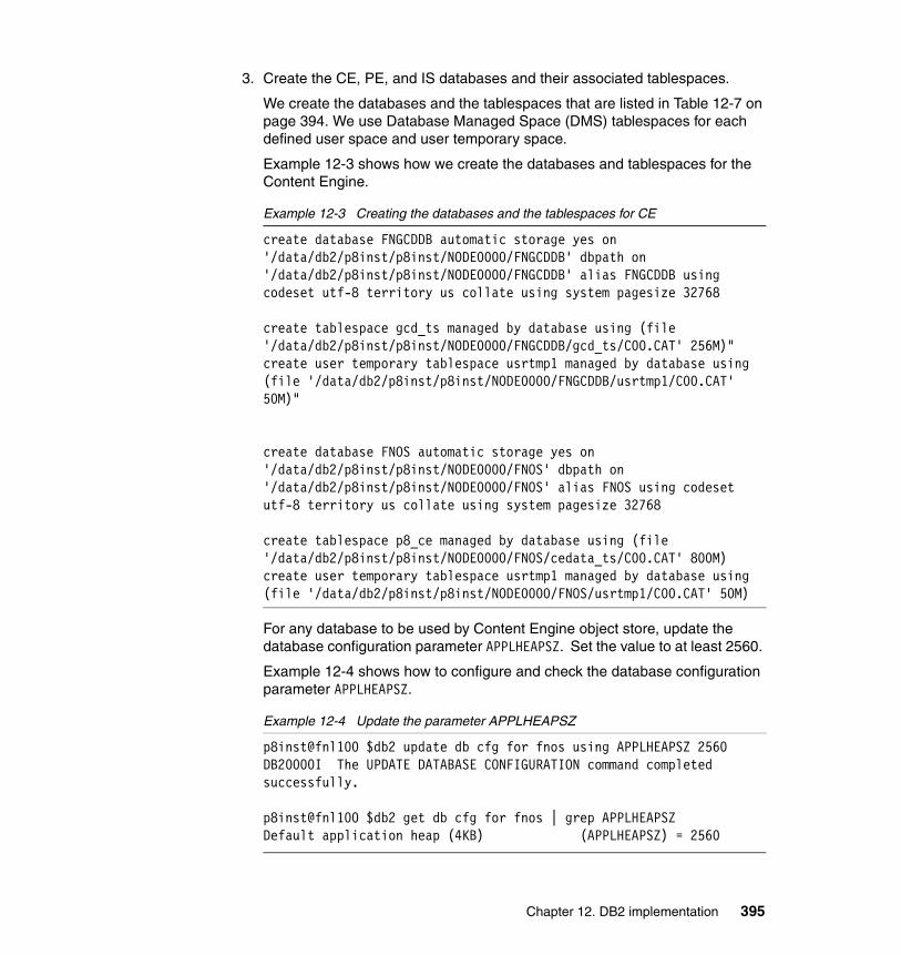
3. Create the CE, PE, and IS databases and their associated tablespaces.
We create the databases and the tablespaces that are listed in Table 12-7 on page 394. We use Database Managed Space (DMS) tablespaces for each defined user space and user temporary space.
Example 12-3 shows how we create the databases and tablespaces for the Content Engine.
Example 12-3 Creating the databases and the tablespaces for CE
create database FNGCDDB automatic storage yes on '/data/db2/p8inst/p8inst/NODE0000/FNGCDDB' dbpath on '/data/db2/p8inst/p8inst/NODE0000/FNGCDDB' alias FNGCDDB using codeset utf-8 territory us collate using system pagesize 32768
create tablespace gcd_ts managed by database using (file '/data/db2/p8inst/p8inst/NODE0000/FNGCDDB/gcd_ts/C00.CAT' 256M)"create user temporary tablespace usrtmp1 managed by database using (file '/data/db2/p8inst/p8inst/NODE0000/FNGCDDB/usrtmp1/C00.CAT' 50M)"
create database FNOS automatic storage yes on '/data/db2/p8inst/p8inst/NODE0000/FNOS' dbpath on '/data/db2/p8inst/p8inst/NODE0000/FNOS' alias FNOS using codeset utf-8 territory us collate using system pagesize 32768
create tablespace p8_ce managed by database using (file '/data/db2/p8inst/p8inst/NODE0000/FNOS/cedata_ts/C00.CAT' 800M)create user temporary tablespace usrtmp1 managed by database using (file '/data/db2/p8inst/p8inst/NODE0000/FNOS/usrtmp1/C00.CAT' 50M)
For any database to be used by Content Engine object store, update the database configuration parameter APPLHEAPSZ. Set the value to at least 2560.
Example 12-4 shows how to configure and check the database configuration parameter APPLHEAPSZ.
Example 12-4 Update the parameter APPLHEAPSZ
p8inst@fnl100 $db2 update db cfg for fnos using APPLHEAPSZ 2560DB20000I The UPDATE DATABASE CONFIGURATION command completed successfully.
p8inst@fnl100 $db2 get db cfg for fnos | grep APPLHEAPSZDefault application heap (4KB) (APPLHEAPSZ) = 2560
Chapter 12. DB2 implementation 395

Example 12-5 shows how we create the database and tablespaces for the Process Engine.
Example 12-5 Creating the database and the tablespaces for PE
create database VWDBHA automatic storage yes on '/data/db2/p8inst/p8inst/NODE0000/VWDBHA' dbpath on '/data/db2/p8inst/p8inst/NODE0000/VWDBHA' alias VWDBHA using codeset utf-8 territory us collate using system pagesize 8192
create tablespace vwdata_ts managed by database using (file '/data/db2/p8inst/p8inst/NODE0000/VWDBHA/vwdata_ts/C00.CAT' 300M)create user temporary tablespace usrtmp1 managed by database using (file '/data/db2/p8inst/p8inst/NODE0000/VWDBHA/usrtmp1/C00.CAT' 50M)
Example 12-6 shows how we create the database for Image Services. We use the default tablespace USERSPACE1 for the IS configuration. No additional tablespaces are defined at this time.
Example 12-6 Creating the database for Image Services
create database INDEXDB automatic storage yes on '/data/db2/p8inst/p8inst/NODE0000/INDEXDB' dbpath on '/data/db2/p8inst/p8inst/NODE0000/INDEXDB' alias INDEXDB using codeset utf-8 territory us collate using system pagesize 32768
12.2.5 Setting up HADR
We set up the HADR for each database that is used in the FileNet configuration. In our scenario, we created databases for the CE, PE, and IS components.
HADR requires that both the primary server and the standby server have the same database configuration. For this purpose, we recommend that you set up the standby system by restoring the database from a backup image of the primary system.
We perform these steps to set up the HADR:
1. Set the required database configuration parameters.
Activate the log archiving mode for the databases. See Example 12-7.
Example 12-7 Activating the database log archiving on disk
db2 update db cfg for fngcddb using LOGARCHMETH1 'DISK:/data/db2/p8inst/archive'
396 IBM High Availability Solution for IBM FileNet P8 Systems

db2 update db cfg for fnos using LOGARCHMETH1 'DISK:/data/db2/p8inst/archive'db2 update db cfg for vwdbha using LOGARCHMETH1 'DISK:/data/db2/p8inst/archive'db2 update db cfg for indexdb using LOGARCHMETH1 'DISK:/data/db2/p8inst/archive'
Set the LOGINDEXBUILD parameter to ON to ensure that the complete information for index creation, recreation, and reorganization is logged, as well as shipped to the standby database during HADR replication. See Example 12-8.
Example 12-8 Enable LOGINDEXBUILD for HADR database
db2 update db cfg for fngcddb using LOGINDEXBUILD ONdb2 update db cfg for fnos using LOGINDEXBUILD ONdb2 update db cfg for vwdbha using LOGINDEXBUILD ONdb2 update db cfg for indexdb using LOGINDEXBUILD ON
2. For each database, perform an offline database backup on the primary system and restore the backup to the standby system.
Example 12-9 shows how we take an offline backup of the database fngcddb on the primary system fnl100. Make sure that you write down the timestamp of the database backup, because you must use it as an input parameter for the restore process.
Example 12-9 Backup up the fngcddb database on the primary system
db2 deactivate db fngcddbDB20000I The DEACTIVATE DATABASE command completed successfully.
db2 backup db FNGCDDB to /data/db2/p8inst/backup
Backup successful. The timestamp for this backup image is : 20081002173801
cd /data/db2/p8inst/backupls -l *20081002173801*-rw------- 1 p8inst p8_igrp 234958848 Oct 02 17:38 FNGCDDB.0.p8inst.NODE0000.CATN0000.20081002173801.001
We copy the backup image using the scp command to our standby system fnl70 to the /data/db2/p8inst/backup directory. The database is then restored as shown in Example 12-10 on page 398.
Chapter 12. DB2 implementation 397
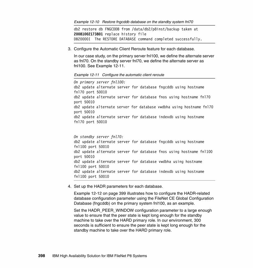
Example 12-10 Restore fngcddb database on the standby system fnl70
db2 restore db FNGCDDB from /data/db2/p8inst/backup taken at 20081002173801 replace history fileDB20000I The RESTORE DATABASE command completed successfully.
3. Configure the Automatic Client Reroute feature for each database.
In our case study, on the primary server fnl100, we define the alternate server as fnl70. On the standby server fnl70, we define the alternate server as fnl100. See Example 12-11.
Example 12-11 Configure the automatic client reroute
On primary server fnl100:db2 update alternate server for database fngcddb using hostname fnl70 port 50010db2 update alternate server for database fnos using hostname fnl70 port 50010db2 update alternate server for database vwdbha using hostname fnl70 port 50010db2 update alternate server for database indexdb using hostname fnl70 port 50010
On standby server fnl70:db2 update alternate server for database fngcddb using hostname fnl100 port 50010db2 update alternate server for database fnos using hostname fnl100 port 50010db2 update alternate server for database vwdbha using hostname fnl100 port 50010db2 update alternate server for database indexdb using hostname fnl100 port 50010
4. Set up the HADR parameters for each database.
Example 12-12 on page 399 illustrates how to configure the HADR-related database configuration parameter using the FileNet CE Global Configuration Database (fngcddb) on the primary system fnl100, as an example.
Set the HADR_PEER_WINDOW configuration parameter to a large enough value to ensure that the peer state is kept long enough for the standby machine to take over the HARD primary role. In our environment, 300 seconds is sufficient to ensure the peer state is kept long enough for the standby machine to take over the HARD primary role.
398 IBM High Availability Solution for IBM FileNet P8 Systems

Example 12-12 Set up HADR parameters on primary node fnl100
db2 update db cfg for fngcddb using HADR_LOCAL_HOST 10.0.4.110db2 update db cfg for fngcddb using HADR_LOCAL_SVC p8_GCDdb2 update db cfg for fngcddb using HADR_REMOTE_HOST 10.0.4.80db2 update db cfg for fngcddb using HADR_REMOTE_SVC p8_GCDdb2 update db cfg for fngcddb using HADR_REMOTE_INST p8instdb2 update db cfg for fngcddb using HADR_SYNCMODE SYNCdb2 update db cfg for fngcddb using HADR_TIMEOUT 120db2 update db cfg for fngcddb using HADR_PEER_WINDOW 300
Example 12-13 shows the HADR configuration parameter setup on the fngcddb database of the standby system fnl70.
Example 12-13 Set up HADR parameters on standby system fnl70
db2 update db cfg for fngcddb using HADR_LOCAL_HOST 10.0.4.80db2 update db cfg for fngcddb using HADR_LOCAL_SVC p8_GCDdb2 update db cfg for fngcddb using HADR_REMOTE_HOST 10.0.4.110db2 update db cfg for fngcddb using HADR_REMOTE_SVC p8_GCDdb2 update db cfg for fngcddb using HADR_REMOTE_INST p8instdb2 update db cfg for fngcddb using HADR_SYNCMODE SYNCdb2 update db cfg for fngcddb using HADR_TIMEOUT 120db2 update db cfg for fngcddb using HADR_PEER_WINDOW 300
5. Activate the HADR relationship.
On each database, start the HADR on the standby system first, and then, on the primary system. In Example 12-14 on page 400, we activate the HADR on the fngcddb database.
Notes: The HADR_LOCAL_SVC and HADR_REMOTE_SVC are the ports that are used by HADR for the primary and standby servers. The value for the HADR_LOCAL_SVC parameter of both the primary and the standby systems cannot be the same as the value of SVCENAME on their respective nodes. Issue the db2 get dbm cfg command to get the service name value of the instance.
The name that we choose is shown in Table 12-4 on page 382 and was added previously to the /etc/services file.
Chapter 12. DB2 implementation 399

Example 12-14 Activate the HADR relationship
On the standby machine fnl70:db2 deactivate db fngcddbdb2 start hadr on db fngcddb as standby
On the primary machine fnl100:db2 deactivate db fngcddbdb2 start hadr on db fngcddb as primary
Check the HADR status for each database using the db2pd utility on both the primary and standby servers as shown in Example 12-15. The Role field shows primary for fnl100 and standby for fnl70. Check also the state of the HADR relationship in the db2pd output, which needs to be Peer and the status of the connection needs to be Connected.
Example 12-15 Checking the HADR status
HADR status on primary system fnl100:
p8inst@fnl100 $db2pd -db fngcddb -hadr
Database Partition 0 -- Database FNGCDDB -- Active -- Up 0 days 02:25:55
HADR Information:Role State SyncMode HeartBeatsMissed LogGapRunAvg (bytes)Primary Peer Sync 0 0
ConnectStatus ConnectTime TimeoutConnected Fri Oct 24 16:16:02 2008 (1224890162) 120
PeerWindowEnd PeerWindowFri Oct 24 17:39:02 2008 (1224895142) 300
LocalHost LocalService10.0.4.110 p8_GCD
RemoteHost RemoteService RemoteInstance10.0.4.80 p8_GCD p8inst
PrimaryFile PrimaryPg PrimaryLSNS0000038.LOG 943 0x000000001BF3772D
StandByFile StandByPg StandByLSNS0000038.LOG 943 0x000000001BF3772D
HADR status on standby system fnl70:p8inst@fnl70 $db2pd -db fngcddb -hadr
Database Partition 0 -- Database FNGCDDB -- Active -- Up 0 days 01:19:08
400 IBM High Availability Solution for IBM FileNet P8 Systems
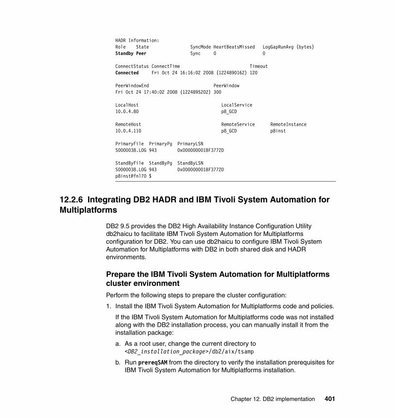
HADR Information:Role State SyncMode HeartBeatsMissed LogGapRunAvg (bytes)Standby Peer Sync 0 0
ConnectStatus ConnectTime TimeoutConnected Fri Oct 24 16:16:02 2008 (1224890162) 120
PeerWindowEnd PeerWindowFri Oct 24 17:40:02 2008 (1224895202) 300
LocalHost LocalService10.0.4.80 p8_GCD
RemoteHost RemoteService RemoteInstance10.0.4.110 p8_GCD p8inst
PrimaryFile PrimaryPg PrimaryLSNS0000038.LOG 943 0x000000001BF3772D
StandByFile StandByPg StandByLSNS0000038.LOG 943 0x000000001BF3772Dp8inst@fnl70 $
12.2.6 Integrating DB2 HADR and IBM Tivoli System Automation for Multiplatforms
DB2 9.5 provides the DB2 High Availability Instance Configuration Utility db2haicu to facilitate IBM Tivoli System Automation for Multiplatforms configuration for DB2. You can use db2haicu to configure IBM Tivoli System Automation for Multiplatforms with DB2 in both shared disk and HADR environments.
Prepare the IBM Tivoli System Automation for Multiplatforms cluster environmentPerform the following steps to prepare the cluster configuration:
1. Install the IBM Tivoli System Automation for Multiplatforms code and policies.
If the IBM Tivoli System Automation for Multiplatforms code was not installed along with the DB2 installation process, you can manually install it from the installation package:
a. As a root user, change the current directory to <DB2_installation_package>/db2/aix/tsamp
b. Run prereqSAM from the directory to verify the installation prerequisites for IBM Tivoli System Automation for Multiplatforms installation.
Chapter 12. DB2 implementation 401

c. Run the script installSAM to install IBM Tivoli System Automation for Multiplatforms.
d. Apply the IBM Tivoli System Automation for Multiplatforms policies for DB2 by running the script db2cptsa, which is located in the directory <DB2_installation_package>/db2/aix/install. The DB2 scripts for the cluster are installed in the directory /usr/sbin/rsct/sapolicies/db2.
2. Synchronize the date and time on the cluster nodes.
You need to synchronize the time and dates on the standby and the primary nodes as closely as possible. This synchronization is absolutely critical to ensure a smooth failover during primary node failures. We recommend using an external Network Time Protocol (NTP) server and configuring the NTP on both cluster nodes. For more details, consult the NTP documentation for your platform.
3. Configure secure shell (SSH).
Secure shell is used in our environment for remote command execution for the root user across the cluster nodes. For IBM Tivoli System Automation for Multiplatforms cluster configuration with ssh, we set up root access between nodes without prompting for a password.
Perform the following steps for a quick SSH setup:
a. Log on as the root on one node of the cluster.
b. Generate a public key/private key pair:
#ssh-keygen -t rsa
When prompted for input, press Enter. Do not enter a passphrase.
c. To enable the new key pair for use with ssh, execute the following commands:
#cat ~/.ssh/id_rsa.pub >> ~/.ssh/authorized_keys
#chmod 644 ~/.ssh/authorized_keys
d. Use the ssh-keyscan utility to gather the public host key for each cluster host. Substitute the IP addresses in the commands with your IP addresses.
#ssh-keyscan -t rsa fnl100,9.30.188.110,fnl70,9.30.188.80 >> ~/.ssh/known_hosts
e. Copy the ~/.ssh directory from the local host to all hosts in the cluster. Assuming the SSH setup was performed on fnl100 node, we copy the directory to fnl70 node:
#scp -p ~/.ssh fnl70:~/.ssh
402 IBM High Availability Solution for IBM FileNet P8 Systems

f. Test that password-less ssh is now enabled. We run the ssh command to cross-check the remote execution of a command without prompting in Example 12-16.
Example 12-16 Test ssh execution between cluster nodes without prompting
root@fnl100 # ssh fnl70 ssh fnl100 dateSun Nov 2 05:21:10 PST 2008
4. Perform the initial configuration:
On all nodes, set the environment variable CT_MANAGEMENT_SCOPE (peer domain scope). All IBM Tivoli System Automation for Multiplatforms users need to permanently set CT_MANAGEMENT_SCOPE to 2 in the root profile:
#vi /.profileexport CT_MANAGEMENT_SCOPE=2
On each cluster node, run the preprpnode command as root to prepare the local node for joining the domain:
# preprpnode fnl100 fnl70
We recommend that you configure the netmon.cf file on each cluster node. This configuration is needed to help Reliable Scalable Cluster Technology (RSCT) services (IBM Tivoli System Automation for Multiplatforms infrastructure) distinguish between adapter and network failure in a single adapter per node per network (equivalency class) configuration. The netmon.cf file is used if broadcast ping is disabled on the system. In this file, supply IBM Tivoli System Automation for Multiplatforms with the IP addresses that are used for the quorum device. This file must contain the IP addresses that can be pinged from both nodes as shown in Example 12-17. The IP addresses that you can choose are the default gateway or the other servers in your system. When the heartbeat stops, IBM Tivoli System Automation for Multiplatforms pings these addresses to determine whether it is a network interface failure or a partner node failure. In Example 12-17, we select the IP addresses 9.30.188.1(default gateway) and other two hosts on the network: 9.30.188.51 and 9.30.188.53.
Example 12-17 Adding hosts on the network in the netmon.cf file
# cat /usr/sbin/cluster/netmon.cf9.30.188.19.30.188.519.30.188.53
Chapter 12. DB2 implementation 403
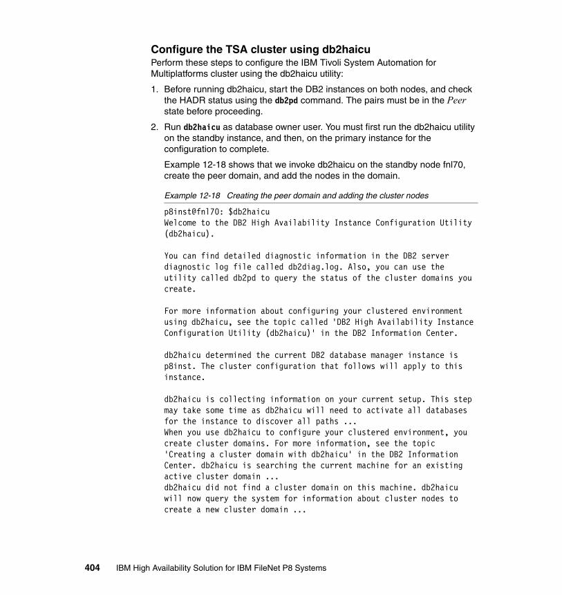
Configure the TSA cluster using db2haicuPerform these steps to configure the IBM Tivoli System Automation for Multiplatforms cluster using the db2haicu utility:
1. Before running db2haicu, start the DB2 instances on both nodes, and check the HADR status using the db2pd command. The pairs must be in the Peer state before proceeding.
2. Run db2haicu as database owner user. You must first run the db2haicu utility on the standby instance, and then, on the primary instance for the configuration to complete.
Example 12-18 shows that we invoke db2haicu on the standby node fnl70, create the peer domain, and add the nodes in the domain.
Example 12-18 Creating the peer domain and adding the cluster nodes
p8inst@fnl70: $db2haicuWelcome to the DB2 High Availability Instance Configuration Utility (db2haicu).
You can find detailed diagnostic information in the DB2 server diagnostic log file called db2diag.log. Also, you can use the utility called db2pd to query the status of the cluster domains you create.
For more information about configuring your clustered environment using db2haicu, see the topic called 'DB2 High Availability Instance Configuration Utility (db2haicu)' in the DB2 Information Center.
db2haicu determined the current DB2 database manager instance is p8inst. The cluster configuration that follows will apply to this instance.
db2haicu is collecting information on your current setup. This step may take some time as db2haicu will need to activate all databases for the instance to discover all paths ...When you use db2haicu to configure your clustered environment, you create cluster domains. For more information, see the topic 'Creating a cluster domain with db2haicu' in the DB2 Information Center. db2haicu is searching the current machine for an existing active cluster domain ...db2haicu did not find a cluster domain on this machine. db2haicu will now query the system for information about cluster nodes to create a new cluster domain ...
404 IBM High Availability Solution for IBM FileNet P8 Systems

db2haicu did not find a cluster domain on this machine. To continue configuring your clustered environment for high availability, you must create a cluster domain; otherwise, db2haicu will exit.
Create a domain and continue? [1]1. Yes2. No1Create a unique name for the new domain:p8db2Nodes must now be added to the new domain.How many cluster nodes will the domain p8db2 contain?2Enter the host name of a machine to add to the domain:fnl70Enter the host name of a machine to add to the domain:fnl100db2haicu can now create a new domain containing the 2 machines that you specified. If you choose not to create a domain now, db2haicu will exit.
Create the domain now? [1]1. Yes2. No1Creating domain p8db2 in the cluster ...Creating domain p8db2 in the cluster was successful.
3. Configure the network quorum device for the cluster. In our case study, we set the default gateway on the public network as the quorum device. See Example 12-19.
Example 12-19 Setting the quorum device
You can now configure a quorum device for the domain. For more information, see the topic "Quorum devices" in the DB2 Information Center. If you do not configure a quorum device for the domain, then a human operator will have to manually intervene if subsets of machines in the cluster lose connectivity.
Configure a quorum device for the domain called p8db2? [1]1. Yes2. No1The following is a list of supported quorum device types:
Chapter 12. DB2 implementation 405

1. Network QuorumEnter the number corresponding to the quorum device type to be used: [1]1Specify the network address of the quorum device:9.30.188.1Configuring quorum device for domain p8db2 ...Configuring quorum device for domain p8db2 was successful.
4. Configure the network interfaces for the cluster for both the public and the private (HADR) networks. See Example 12-20.
Example 12-20 Configure the network interfaces
The cluster manager found 6 network interface cards on the machines in the domain. You can use db2haicu to create networks for these network interface cards. For more information, see the topic 'Creating networks with db2haicu' in the DB2 Information Center.
Create networks for these network interface cards? [1]1. Yes2. No1Enter the name of the network for the network interface card: en0 on cluster node: fnl1001. Create a new public network for this network interface card.2. Create a new private network for this network interface card.Enter selection:2Are you sure you want to add the network interface card en0 on cluster node fnl100 to the network db2_private_network_0? [1]1. Yes2. No2Enter the name of the network for the network interface card: en1 on cluster node: fnl701. Create a new public network for this network interface card.2. Create a new private network for this network interface card.Enter selection:2Are you sure you want to add the network interface card en1 on cluster node fnl70 to the network db2_private_network_0? [1]1. Yes2. No2
406 IBM High Availability Solution for IBM FileNet P8 Systems

Enter the name of the network for the network interface card: en3 on cluster node: fnl701. Create a new public network for this network interface card.2. Create a new private network for this network interface card.Enter selection:2Are you sure you want to add the network interface card en3 on cluster node fnl70 to the network db2_private_network_0? [1]1. Yes2. No1Adding network interface card en3 on cluster node fnl70 to the network db2_private_network_0 ...Adding network interface card en3 on cluster node fnl70 to the network db2_private_network_0 was successful.Enter the name of the network for the network interface card: en3 on cluster node: fnl1001. db2_private_network_02. Create a new public network for this network interface card.3. Create a new private network for this network interface card.Enter selection:1Are you sure you want to add the network interface card en3 on cluster node fnl100 to the network db2_private_network_0? [1]1. Yes2. No1Adding network interface card en3 on cluster node fnl100 to the network db2_private_network_0 ...Adding network interface card en3 on cluster node fnl100 to the network db2_private_network_0 was successful.Enter the name of the network for the network interface card: en0 on cluster node: fnl701. db2_private_network_02. Create a new public network for this network interface card.3. Create a new private network for this network interface card.Enter selection:2Are you sure you want to add the network interface card en0 on cluster node fnl70 to the network db2_public_network_0? [1]1. Yes2. No1Adding network interface card en0 on cluster node fnl70 to the network db2_public_network_0 ...
Chapter 12. DB2 implementation 407
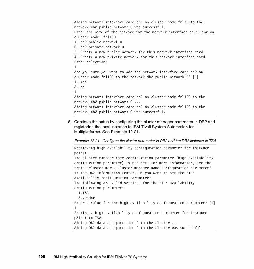
Adding network interface card en0 on cluster node fnl70 to the network db2_public_network_0 was successful.Enter the name of the network for the network interface card: en2 on cluster node: fnl1001. db2_public_network_02. db2_private_network_03. Create a new public network for this network interface card.4. Create a new private network for this network interface card.Enter selection:1Are you sure you want to add the network interface card en2 on cluster node fnl100 to the network db2_public_network_0? [1]1. Yes2. No1Adding network interface card en2 on cluster node fnl100 to the network db2_public_network_0 ...Adding network interface card en2 on cluster node fnl100 to the network db2_public_network_0 was successful.
5. Continue the setup by configuring the cluster manager parameter in DB2 and registering the local instance to IBM Tivoli System Automation for Multiplatforms. See Example 12-21.
Example 12-21 Configure the cluster parameter in DB2 and the DB2 instance in TSA
Retrieving high availability configuration parameter for instance p8inst ...The cluster manager name configuration parameter (high availability configuration parameter) is not set. For more information, see the topic "cluster_mgr - Cluster manager name configuration parameter" in the DB2 Information Center. Do you want to set the high availability configuration parameter?The following are valid settings for the high availability configuration parameter: 1.TSA 2.VendorEnter a value for the high availability configuration parameter: [1]1Setting a high availability configuration parameter for instance p8inst to TSA.Adding DB2 database partition 0 to the cluster ...Adding DB2 database partition 0 to the cluster was successful.
408 IBM High Availability Solution for IBM FileNet P8 Systems
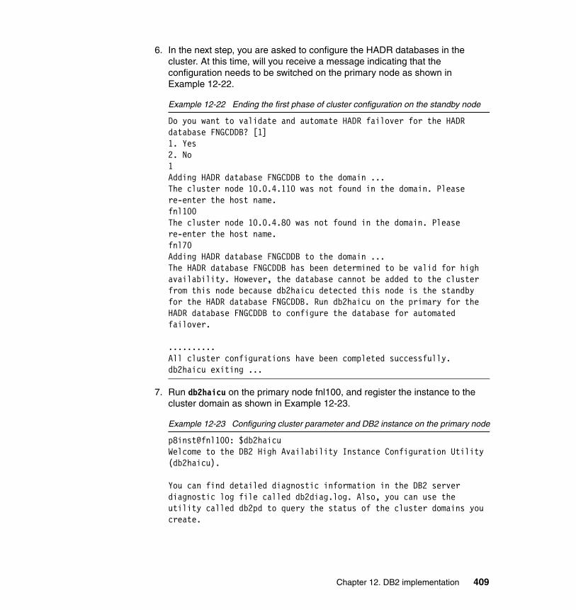
6. In the next step, you are asked to configure the HADR databases in the cluster. At this time, will you receive a message indicating that the configuration needs to be switched on the primary node as shown in Example 12-22.
Example 12-22 Ending the first phase of cluster configuration on the standby node
Do you want to validate and automate HADR failover for the HADR database FNGCDDB? [1]1. Yes2. No1Adding HADR database FNGCDDB to the domain ...The cluster node 10.0.4.110 was not found in the domain. Please re-enter the host name.fnl100The cluster node 10.0.4.80 was not found in the domain. Please re-enter the host name.fnl70Adding HADR database FNGCDDB to the domain ...The HADR database FNGCDDB has been determined to be valid for high availability. However, the database cannot be added to the cluster from this node because db2haicu detected this node is the standby for the HADR database FNGCDDB. Run db2haicu on the primary for the HADR database FNGCDDB to configure the database for automated failover.
..........All cluster configurations have been completed successfully. db2haicu exiting ...
7. Run db2haicu on the primary node fnl100, and register the instance to the cluster domain as shown in Example 12-23.
Example 12-23 Configuring cluster parameter and DB2 instance on the primary node
p8inst@fnl100: $db2haicuWelcome to the DB2 High Availability Instance Configuration Utility (db2haicu).
You can find detailed diagnostic information in the DB2 server diagnostic log file called db2diag.log. Also, you can use the utility called db2pd to query the status of the cluster domains you create.
Chapter 12. DB2 implementation 409

For more information about configuring your clustered environment using db2haicu, see the topic called 'DB2 High Availability Instance Configuration Utility (db2haicu)' in the DB2 Information Center.
db2haicu determined the current DB2 database manager instance is p8inst. The cluster configuration that follows will apply to this instance.
db2haicu is collecting information on your current setup. This step may take some time as db2haicu will need to activate all databases for the instance to discover all paths ...When you use db2haicu to configure your clustered environment, you create cluster domains. For more information, see the topic 'Creating a cluster domain with db2haicu' in the DB2 Information Center. db2haicu is searching the current machine for an existing active cluster domain ...db2haicu found a cluster domain called p8db2 on this machine. The cluster configuration that follows will apply to this domain.
Retrieving high availability configuration parameter for instance p8inst ...The cluster manager name configuration parameter (high availability configuration parameter) is not set. For more information, see the topic "cluster_mgr - Cluster manager name configuration parameter" in the DB2 Information Center. Do you want to set the high availability configuration parameter?The following are valid settings for the high availability configuration parameter: 1.TSA 2.VendorEnter a value for the high availability configuration parameter: [1]1Setting a high availability configuration parameter for instance p8inst to TSA.Adding DB2 database partition 0 to the cluster ...Adding DB2 database partition 0 to the cluster was successful.
8. In the next step, add each HADR database to the cluster domain as shown in Example 12-24 for the fngcddb database.
Example 12-24 Adding the HADR database to the cluster domain
Do you want to validate and automate HADR failover for the HADR database FNGCDDB? [1]1. Yes
410 IBM High Availability Solution for IBM FileNet P8 Systems

2. No1Adding HADR database FNGCDDB to the domain ...The cluster node 10.0.4.80 was not found in the domain. Please re-enter the host name.fnl70The cluster node 10.0.4.110 was not found in the domain. Please re-enter the host name.fnl100Adding HADR database FNGCDDB to the domain ...Adding HADR database FNGCDDB to the domain was successful.............All cluster configurations have been completed successfully. db2haicu exiting ...
9. After adding an HADR database, you can set up a Virtual IP address for the database. We do not configure a virtual address, because we use ACR for our setup. Finish the db2haicu setup on the primary node after adding all of the FileNet HADR databases to the cluster domain.
At the end of the configuration, the cluster resources are configured and in an active status in the cluster. The status of the resource groups can be queried using the lssam command as indicated in Example 12-25. For each DB2 instance, note the Online status on each node. For the HADR pairs, note the Online status on the primary node and the Offline status on the standby node.
Example 12-25 Checking the Resource groups status using lssam
root@fnl100 # lssamOnline IBM.ResourceGroup:db2_p8inst_fnl100_0-rg Nominal=Online '- Online IBM.Application:db2_p8inst_fnl100_0-rs '- Online IBM.Application:db2_p8inst_fnl100_0-rs:fnl100Online IBM.ResourceGroup:db2_p8inst_fnl70_0-rg Nominal=Online '- Online IBM.Application:db2_p8inst_fnl70_0-rs '- Online IBM.Application:db2_p8inst_fnl70_0-rs:fnl70Online IBM.ResourceGroup:db2_p8inst_p8inst_FNGCDDB-rg Nominal=Online '- Online IBM.Application:db2_p8inst_p8inst_FNGCDDB-rs |- Online IBM.Application:db2_p8inst_p8inst_FNGCDDB-rs:fnl100 '- Offline IBM.Application:db2_p8inst_p8inst_FNGCDDB-rs:fnl70Online IBM.ResourceGroup:db2_p8inst_p8inst_FNOS-rg Nominal=Online '- Online IBM.Application:db2_p8inst_p8inst_FNOS-rs |- Online IBM.Application:db2_p8inst_p8inst_FNOS-rs:fnl100 '- Offline IBM.Application:db2_p8inst_p8inst_FNOS-rs:fnl70Online IBM.ResourceGroup:db2_p8inst_p8inst_INDEXDB-rg Nominal=Online '- Online IBM.Application:db2_p8inst_p8inst_INDEXDB-rs |- Online IBM.Application:db2_p8inst_p8inst_INDEXDB-rs:fnl100 '- Offline IBM.Application:db2_p8inst_p8inst_INDEXDB-rs:fnl70
Chapter 12. DB2 implementation 411
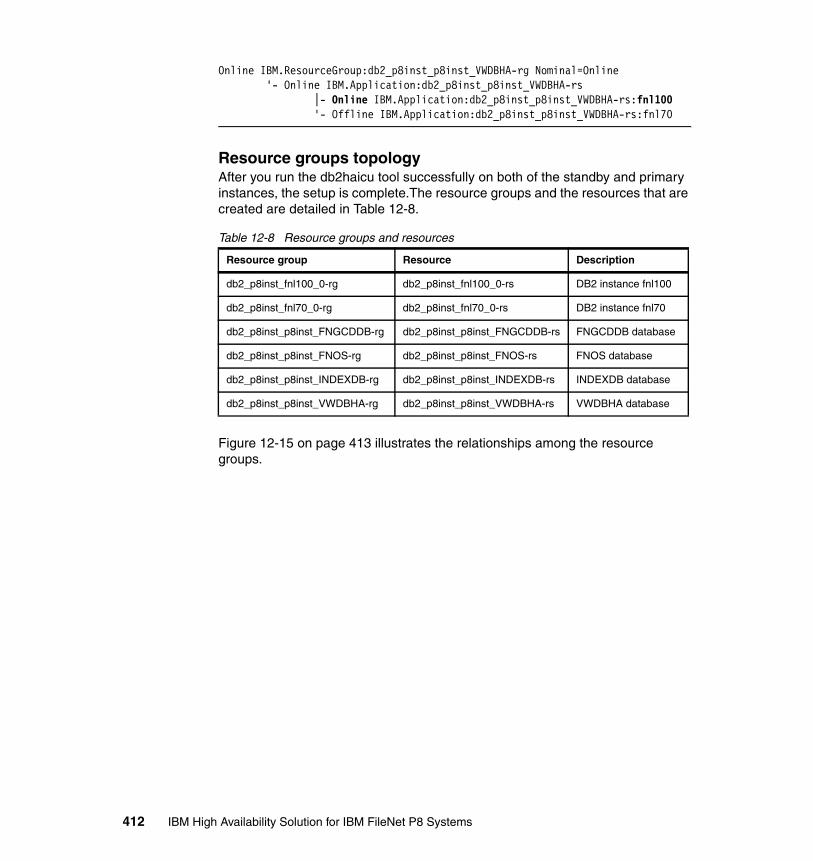
Online IBM.ResourceGroup:db2_p8inst_p8inst_VWDBHA-rg Nominal=Online '- Online IBM.Application:db2_p8inst_p8inst_VWDBHA-rs |- Online IBM.Application:db2_p8inst_p8inst_VWDBHA-rs:fnl100 '- Offline IBM.Application:db2_p8inst_p8inst_VWDBHA-rs:fnl70
Resource groups topologyAfter you run the db2haicu tool successfully on both of the standby and primary instances, the setup is complete.The resource groups and the resources that are created are detailed in Table 12-8.
Table 12-8 Resource groups and resources
Figure 12-15 on page 413 illustrates the relationships among the resource groups.
Resource group Resource Description
db2_p8inst_fnl100_0-rg db2_p8inst_fnl100_0-rs DB2 instance fnl100
db2_p8inst_fnl70_0-rg db2_p8inst_fnl70_0-rs DB2 instance fnl70
db2_p8inst_p8inst_FNGCDDB-rg db2_p8inst_p8inst_FNGCDDB-rs FNGCDDB database
db2_p8inst_p8inst_FNOS-rg db2_p8inst_p8inst_FNOS-rs FNOS database
db2_p8inst_p8inst_INDEXDB-rg db2_p8inst_p8inst_INDEXDB-rs INDEXDB database
db2_p8inst_p8inst_VWDBHA-rg db2_p8inst_p8inst_VWDBHA-rs VWDBHA database
412 IBM High Availability Solution for IBM FileNet P8 Systems
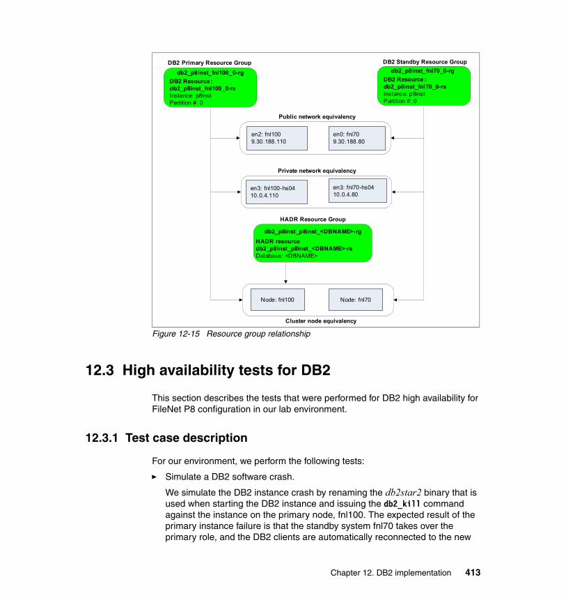
Figure 12-15 Resource group relationship
12.3 High availability tests for DB2
This section describes the tests that were performed for DB2 high availability for FileNet P8 configuration in our lab environment.
12.3.1 Test case description
For our environment, we perform the following tests:
� Simulate a DB2 software crash.
We simulate the DB2 instance crash by renaming the db2star2 binary that is used when starting the DB2 instance and issuing the db2_kill command against the instance on the primary node, fnl100. The expected result of the primary instance failure is that the standby system fnl70 takes over the primary role, and the DB2 clients are automatically reconnected to the new
db2_p8inst_fnl100_0-rgDB2 Resource : db2_p8inst_fnl100_0-rsInstance: p8instPartition #: 0
db2_p8inst_fnl70_0-rgDB2 Resource: db2_p8inst_fnl70_0-rsInstance: p8instPartition #: 0
DB2 Primary Resource Group DB2 Standby Resource Group
en2: fnl1009.30.188.110
en0: fnl709.30.188.80
Public network equivalency
Private network equivalency
en3: fnl100-hs0410.0.4.110
en3: fnl70-hs0410.0.4.80
Cluster node equivalency
Node: fnl100 Node: fnl70
HADR Resource Group
db2_p8inst_p8inst_<DBNAME>-rgHADR resourcedb2_p8inst_p8inst_<DBNAME>-rsDatabase: <DBNAME>
Chapter 12. DB2 implementation 413

server by ACR. The HADR cluster resources are activated on the new primary server, fnl70.
� Simulate a primary node failure.
We simulate a node failure by halting the primary node fnl100 using thehalt -q command on AIX. The HADR cluster resources are taken over to the standby node fnl70, and the databases are activated for client access.
� Simulate a network interface failure.
We simulate a network interface failure on the public network on the primary node by bringing the interface down using the ifconfig command. Because we have defined a dependency between the DB2 instances on each node and the public network equivalency, we expect that this event is determined to be the primary instance failure and a takeover on the standby system results.
For each test, we perform the indicated operations to simulate the failure and provide the steps performed in our environment to reintegrate the failed node or resources back in the cluster.
For determining the cluster status, use the lssam command. For checking the HADR status, use the db2pd command. For our environment, we created a sample script, which greps the summary information status from the db2pd output, listed in Example 12-26.
Example 12-26 Sample script for checking the HADR status
#!/bin/ksh
DBNAME=$1DBs="fngcddb indexdb fnos vwdbha"
if [[ $DBNAME == "" ]]; then echo "Usage: $0 <DBNAME|all>" exit 0fi
if [[ $DBNAME == "all" ]]; thenfor i in $DBsdoecho "Summary status for $i:"db2pd -db $i -hadr | grep -p Roledone
elsedb2pd -db $DBNAME -hadr | grep -p Rolefi
414 IBM High Availability Solution for IBM FileNet P8 Systems

Initial state of the clusterThe initial state of the cluster for each test assumes that the primary system for HADR is fnl100 and that the standby system is fnl70. The DB2 instances are started, and the HADR pairs are active in Peer state. Use lssam to determine the cluster state as shown in Example 12-27.
Example 12-27 Cluster initial state
root@fnl100 # lssamOnline IBM.ResourceGroup:db2_p8inst_fnl100_0-rg Nominal=Online '- Online IBM.Application:db2_p8inst_fnl100_0-rs '- Online IBM.Application:db2_p8inst_fnl100_0-rs:fnl100Online IBM.ResourceGroup:db2_p8inst_fnl70_0-rg Nominal=Online '- Online IBM.Application:db2_p8inst_fnl70_0-rs '- Online IBM.Application:db2_p8inst_fnl70_0-rs:fnl70Online IBM.ResourceGroup:db2_p8inst_p8inst_FNGCDDB-rg Nominal=Online '- Online IBM.Application:db2_p8inst_p8inst_FNGCDDB-rs |- Online IBM.Application:db2_p8inst_p8inst_FNGCDDB-rs:fnl100 '- Offline IBM.Application:db2_p8inst_p8inst_FNGCDDB-rs:fnl70Online IBM.ResourceGroup:db2_p8inst_p8inst_FNOS-rg Nominal=Online '- Online IBM.Application:db2_p8inst_p8inst_FNOS-rs |- Online IBM.Application:db2_p8inst_p8inst_FNOS-rs:fnl100 '- Offline IBM.Application:db2_p8inst_p8inst_FNOS-rs:fnl70Online IBM.ResourceGroup:db2_p8inst_p8inst_INDEXDB-rg Nominal=Online '- Online IBM.Application:db2_p8inst_p8inst_INDEXDB-rs |- Online IBM.Application:db2_p8inst_p8inst_INDEXDB-rs:fnl100 '- Offline IBM.Application:db2_p8inst_p8inst_INDEXDB-rs:fnl70Online IBM.ResourceGroup:db2_p8inst_p8inst_VWDBHA-rg Nominal=Online '- Online IBM.Application:db2_p8inst_p8inst_VWDBHA-rs |- Online IBM.Application:db2_p8inst_p8inst_VWDBHA-rs:fnl100 '- Offline IBM.Application:db2_p8inst_p8inst_VWDBHA-rs:fnl70
We check the HADR pair status using the script that is provided in Example 12-26 on page 414. The result of running the script on the primary and standby servers is displayed in Example 12-28.
Example 12-28 Checking the HADR pair status
On primary node fnl100:p8inst@fnl100 $checkhadr.sh allSummary status for fngcddb:HADR Information:Role State SyncMode HeartBeatsMissed LogGapRunAvg (bytes)Primary Peer Sync 0 0
Summary status for indexdb:HADR Information:Role State SyncMode HeartBeatsMissed LogGapRunAvg (bytes)
Chapter 12. DB2 implementation 415
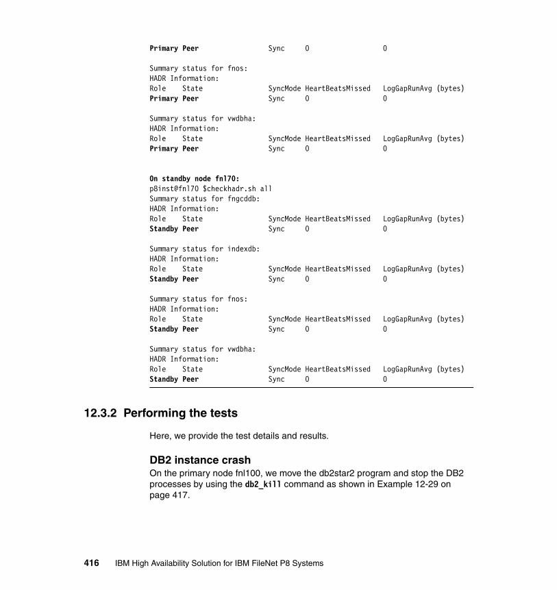
Primary Peer Sync 0 0
Summary status for fnos:HADR Information:Role State SyncMode HeartBeatsMissed LogGapRunAvg (bytes)Primary Peer Sync 0 0
Summary status for vwdbha:HADR Information:Role State SyncMode HeartBeatsMissed LogGapRunAvg (bytes)Primary Peer Sync 0 0
On standby node fnl70:p8inst@fnl70 $checkhadr.sh allSummary status for fngcddb:HADR Information:Role State SyncMode HeartBeatsMissed LogGapRunAvg (bytes)Standby Peer Sync 0 0
Summary status for indexdb:HADR Information:Role State SyncMode HeartBeatsMissed LogGapRunAvg (bytes)Standby Peer Sync 0 0
Summary status for fnos:HADR Information:Role State SyncMode HeartBeatsMissed LogGapRunAvg (bytes)Standby Peer Sync 0 0
Summary status for vwdbha:HADR Information:Role State SyncMode HeartBeatsMissed LogGapRunAvg (bytes)Standby Peer Sync 0 0
12.3.2 Performing the tests
Here, we provide the test details and results.
DB2 instance crashOn the primary node fnl100, we move the db2star2 program and stop the DB2 processes by using the db2_kill command as shown in Example 12-29 on page 417.
416 IBM High Availability Solution for IBM FileNet P8 Systems

Example 12-29 DB2 instance failure on primary node fnl100
p8inst@fnl100 $mv /data/db2/p8_inst/sqllib/adm/db2star2 /data/db2/p8_inst/sqllib/adm/db2star2.mvp8inst@fnl100 $db2_killipclean: Removing DB2 engine and client's IPC resources for p8inst.p8inst@fnl100 $
The HADR resources are activated on the standby node fnl70, and the DB2 instance resource on fnl100 is finally marked “Failed Offline” as shown in Example 12-30.
Example 12-30 HADR takeover on fnl70
root@fnl70 # lssamFailed offline IBM.ResourceGroup:db2_p8inst_fnl100_0-rg Nominal=Online '- Failed offline IBM.Application:db2_p8inst_fnl100_0-rs '- Failed offline IBM.Application:db2_p8inst_fnl100_0-rs:fnl100Online IBM.ResourceGroup:db2_p8inst_fnl70_0-rg Nominal=Online '- Online IBM.Application:db2_p8inst_fnl70_0-rs '- Online IBM.Application:db2_p8inst_fnl70_0-rs:fnl70Pending offline IBM.ResourceGroup:db2_p8inst_p8inst_FNGCDDB-rg Request=Lock Nominal=Online '- Online IBM.Application:db2_p8inst_p8inst_FNGCDDB-rs |- Offline IBM.Application:db2_p8inst_p8inst_FNGCDDB-rs:fnl100 '- Online IBM.Application:db2_p8inst_p8inst_FNGCDDB-rs:fnl70Pending offline IBM.ResourceGroup:db2_p8inst_p8inst_FNOS-rg Request=Lock Binding=Sacrificial Nominal=Online '- Online IBM.Application:db2_p8inst_p8inst_FNOS-rs |- Failed offline IBM.Application:db2_p8inst_p8inst_FNOS-rs:fnl100 '- Online IBM.Application:db2_p8inst_p8inst_FNOS-rs:fnl70Pending offline IBM.ResourceGroup:db2_p8inst_p8inst_INDEXDB-rg Request=Lock Nominal=Online '- Online IBM.Application:db2_p8inst_p8inst_INDEXDB-rs |- Offline IBM.Application:db2_p8inst_p8inst_INDEXDB-rs:fnl100 '- Online IBM.Application:db2_p8inst_p8inst_INDEXDB-rs:fnl70Online IBM.ResourceGroup:db2_p8inst_p8inst_VWDBHA-rg Request=Lock Nominal=Online '- Online IBM.Application:db2_p8inst_p8inst_VWDBHA-rs |- Offline IBM.Application:db2_p8inst_p8inst_VWDBHA-rs:fnl100 '- Online IBM.Application:db2_p8inst_p8inst_VWDBHA-rs:fnl70
We also check that the primary role was successfully taken over to node fnl70. See Example 12-31 on page 418.
Chapter 12. DB2 implementation 417
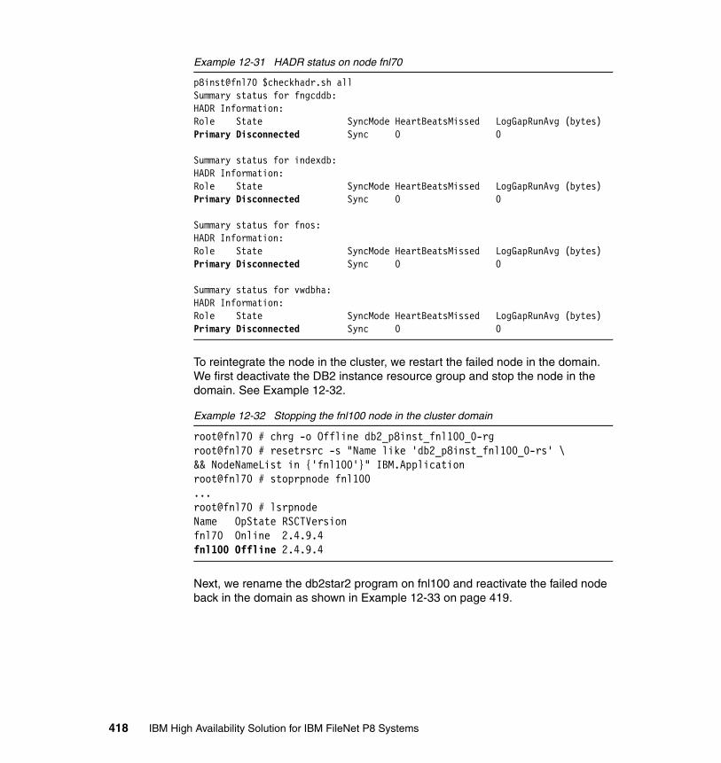
Example 12-31 HADR status on node fnl70
p8inst@fnl70 $checkhadr.sh allSummary status for fngcddb:HADR Information:Role State SyncMode HeartBeatsMissed LogGapRunAvg (bytes)Primary Disconnected Sync 0 0
Summary status for indexdb:HADR Information:Role State SyncMode HeartBeatsMissed LogGapRunAvg (bytes)Primary Disconnected Sync 0 0
Summary status for fnos:HADR Information:Role State SyncMode HeartBeatsMissed LogGapRunAvg (bytes)Primary Disconnected Sync 0 0
Summary status for vwdbha:HADR Information:Role State SyncMode HeartBeatsMissed LogGapRunAvg (bytes)Primary Disconnected Sync 0 0
To reintegrate the node in the cluster, we restart the failed node in the domain. We first deactivate the DB2 instance resource group and stop the node in the domain. See Example 12-32.
Example 12-32 Stopping the fnl100 node in the cluster domain
root@fnl70 # chrg -o Offline db2_p8inst_fnl100_0-rgroot@fnl70 # resetrsrc -s "Name like 'db2_p8inst_fnl100_0-rs' \&& NodeNameList in {'fnl100'}" IBM.Applicationroot@fnl70 # stoprpnode fnl100...root@fnl70 # lsrpnodeName OpState RSCTVersionfnl70 Online 2.4.9.4fnl100 Offline 2.4.9.4
Next, we rename the db2star2 program on fnl100 and reactivate the failed node back in the domain as shown in Example 12-33 on page 419.
418 IBM High Availability Solution for IBM FileNet P8 Systems

Example 12-33 Reintegrating the failed node in the domain
On fnl100:p8inst@fnl100 $mv /data/db2/p8_inst/sqllib/adm/db2star2.mv \ /data/db2/p8_inst/sqllib/adm/db2star2
On fnl70:root@fnl70 # startrpnode fnl100.....root@fnl70 # lsrpnodeName OpState RSCTVersionfnl70 Online 2.4.9.4fnl100 Online 2.4.9.4root@fnl70 # chrg -o Online db2_p8inst_fnl100_0-rg
After restarting the DB2 instance on the fnl100 node, the HADR is automatically started and the node reintegrates in the HADR relationship as a standby node. The final cluster status in shown in Example 12-34.
Example 12-34 Final cluster status after reintegration of node fnl100
root@fnl70 # lssamOnline IBM.ResourceGroup:db2_p8inst_fnl100_0-rg Nominal=Online '- Online IBM.Application:db2_p8inst_fnl100_0-rs '- Online IBM.Application:db2_p8inst_fnl100_0-rs:fnl100Online IBM.ResourceGroup:db2_p8inst_fnl70_0-rg Nominal=Online '- Online IBM.Application:db2_p8inst_fnl70_0-rs '- Online IBM.Application:db2_p8inst_fnl70_0-rs:fnl70Online IBM.ResourceGroup:db2_p8inst_p8inst_FNGCDDB-rg Nominal=Online '- Online IBM.Application:db2_p8inst_p8inst_FNGCDDB-rs |- Offline IBM.Application:db2_p8inst_p8inst_FNGCDDB-rs:fnl100 '- Online IBM.Application:db2_p8inst_p8inst_FNGCDDB-rs:fnl70Online IBM.ResourceGroup:db2_p8inst_p8inst_FNOS-rg Nominal=Online '- Online IBM.Application:db2_p8inst_p8inst_FNOS-rs |- Offline IBM.Application:db2_p8inst_p8inst_FNOS-rs:fnl100 '- Online IBM.Application:db2_p8inst_p8inst_FNOS-rs:fnl70Online IBM.ResourceGroup:db2_p8inst_p8inst_INDEXDB-rg Nominal=Online '- Online IBM.Application:db2_p8inst_p8inst_INDEXDB-rs |- Offline IBM.Application:db2_p8inst_p8inst_INDEXDB-rs:fnl100 '- Online IBM.Application:db2_p8inst_p8inst_INDEXDB-rs:fnl70Online IBM.ResourceGroup:db2_p8inst_p8inst_VWDBHA-rg Nominal=Online '- Online IBM.Application:db2_p8inst_p8inst_VWDBHA-rs |- Offline IBM.Application:db2_p8inst_p8inst_VWDBHA-rs:fnl100 '- Online IBM.Application:db2_p8inst_p8inst_VWDBHA-rs:fnl70
Chapter 12. DB2 implementation 419

Primary node crashThis test simulates a node failure by halting the primary node, fnl100, during normal operations. We run the test by invoking the halt -q command on node fnl100. The cluster HADR resources are automatically taken over on the standby node fnl70, and the databases are activated for client access. See Example 12-35.
Example 12-35 Cluster status after node fnl100 failure
root@fnl70 # lssamFailed offline IBM.ResourceGroup:db2_p8inst_fnl100_0-rg Control=StartInhibited Nominal=Online '- Failed offline IBM.Application:db2_p8inst_fnl100_0-rs '- Failed offline IBM.Application:db2_p8inst_fnl100_0-rs:fnl100 Node=OfflineOnline IBM.ResourceGroup:db2_p8inst_fnl70_0-rg Nominal=Online '- Online IBM.Application:db2_p8inst_fnl70_0-rs '- Online IBM.Application:db2_p8inst_fnl70_0-rs:fnl70Online IBM.ResourceGroup:db2_p8inst_p8inst_FNGCDDB-rg Request=Lock Nominal=Online '- Online IBM.Application:db2_p8inst_p8inst_FNGCDDB-rs |- Failed offline IBM.Application:db2_p8inst_p8inst_FNGCDDB-rs:fnl100 Node=Offline '- Online IBM.Application:db2_p8inst_p8inst_FNGCDDB-rs:fnl70Online IBM.ResourceGroup:db2_p8inst_p8inst_FNOS-rg Request=Lock Nominal=Online '- Online IBM.Application:db2_p8inst_p8inst_FNOS-rs |- Failed offline IBM.Application:db2_p8inst_p8inst_FNOS-rs:fnl100 Node=Offline '- Online IBM.Application:db2_p8inst_p8inst_FNOS-rs:fnl70Online IBM.ResourceGroup:db2_p8inst_p8inst_INDEXDB-rg Request=Lock Nominal=Online '- Online IBM.Application:db2_p8inst_p8inst_INDEXDB-rs |- Failed offline IBM.Application:db2_p8inst_p8inst_INDEXDB-rs:fnl100 Node=Offline '- Online IBM.Application:db2_p8inst_p8inst_INDEXDB-rs:fnl70Online IBM.ResourceGroup:db2_p8inst_p8inst_VWDBHA-rg Request=Lock Nominal=Online '- Online IBM.Application:db2_p8inst_p8inst_VWDBHA-rs |- Failed offline IBM.Application:db2_p8inst_p8inst_VWDBHA-rs:fnl100 Node=Offline '- Online IBM.Application:db2_p8inst_p8inst_VWDBHA-rs:fnl70
After restarting the failed node, fnl100, the node reintegrates automatically in the cluster domain. The DB2 instance starts, and the node reintegrates in the HADR relationship as standby node. Example 12-36 on page 421 shows the final cluster status.
420 IBM High Availability Solution for IBM FileNet P8 Systems
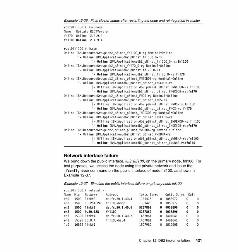
Example 12-36 Final cluster status after restarting the node and reintegration in cluster
root@fnl100 # lsrpnodeName OpState RSCTVersionfnl70 Online 2.4.9.4fnl100 Online 2.4.9.4
root@fnl100 # lssamOnline IBM.ResourceGroup:db2_p8inst_fnl100_0-rg Nominal=Online '- Online IBM.Application:db2_p8inst_fnl100_0-rs '- Online IBM.Application:db2_p8inst_fnl100_0-rs:fnl100Online IBM.ResourceGroup:db2_p8inst_fnl70_0-rg Nominal=Online '- Online IBM.Application:db2_p8inst_fnl70_0-rs '- Online IBM.Application:db2_p8inst_fnl70_0-rs:fnl70Online IBM.ResourceGroup:db2_p8inst_p8inst_FNGCDDB-rg Nominal=Online '- Online IBM.Application:db2_p8inst_p8inst_FNGCDDB-rs |- Offline IBM.Application:db2_p8inst_p8inst_FNGCDDB-rs:fnl100 '- Online IBM.Application:db2_p8inst_p8inst_FNGCDDB-rs:fnl70Online IBM.ResourceGroup:db2_p8inst_p8inst_FNOS-rg Nominal=Online '- Online IBM.Application:db2_p8inst_p8inst_FNOS-rs |- Offline IBM.Application:db2_p8inst_p8inst_FNOS-rs:fnl100 '- Online IBM.Application:db2_p8inst_p8inst_FNOS-rs:fnl70Online IBM.ResourceGroup:db2_p8inst_p8inst_INDEXDB-rg Nominal=Online '- Online IBM.Application:db2_p8inst_p8inst_INDEXDB-rs |- Offline IBM.Application:db2_p8inst_p8inst_INDEXDB-rs:fnl100 '- Online IBM.Application:db2_p8inst_p8inst_INDEXDB-rs:fnl70Online IBM.ResourceGroup:db2_p8inst_p8inst_VWDBHA-rg Nominal=Online '- Online IBM.Application:db2_p8inst_p8inst_VWDBHA-rs |- Offline IBM.Application:db2_p8inst_p8inst_VWDBHA-rs:fnl100 '- Online IBM.Application:db2_p8inst_p8inst_VWDBHA-rs:fnl70
Network interface failureWe bring down the public interface, en2:fnl100, on the primary node, fnl100. For test purposes, we access the node using the private network and issue the ifconfig down command on the public interface of node fnl100, as shown in Example 12-37.
Example 12-37 Simulate the public interface failure on primary node fnl100
root@fnl100 # netstat -iName Mtu Network Address Ipkts Ierrs Opkts Oerrs Collen0 1500 link#2 de.fc.50.1.40.4 1183425 0 1053977 0 0en0 1500 10.254.240 fnl100-hmcp 1183425 0 1053977 0 0en2 1500 link#3 de.fc.50.1.40.6 5237869 0 4038896 0 0en2 1500 9.30.188 fnl100 5237869 0 4038896 0 0en3 65390 link#4 de.fc.50.1.40.7 1467861 0 1401041 0 0en3 65390 10.0.4 fnl100-hs04 1467861 0 1401041 0 0lo0 16896 link#1 1507980 0 1510605 0 0
Chapter 12. DB2 implementation 421
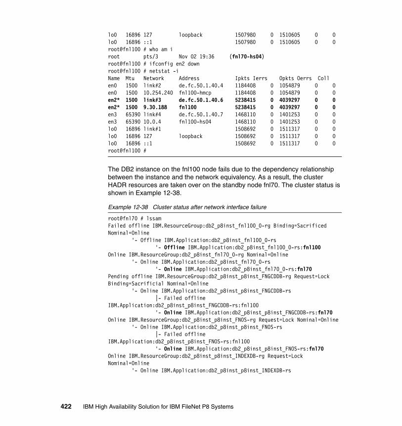
lo0 16896 127 loopback 1507980 0 1510605 0 0lo0 16896 ::1 1507980 0 1510605 0 0root@fnl100 # who am iroot pts/3 Nov 02 19:36 (fnl70-hs04)root@fnl100 # ifconfig en2 downroot@fnl100 # netstat -iName Mtu Network Address Ipkts Ierrs Opkts Oerrs Collen0 1500 link#2 de.fc.50.1.40.4 1184408 0 1054879 0 0en0 1500 10.254.240 fnl100-hmcp 1184408 0 1054879 0 0en2* 1500 link#3 de.fc.50.1.40.6 5238415 0 4039297 0 0en2* 1500 9.30.188 fnl100 5238415 0 4039297 0 0en3 65390 link#4 de.fc.50.1.40.7 1468110 0 1401253 0 0en3 65390 10.0.4 fnl100-hs04 1468110 0 1401253 0 0lo0 16896 link#1 1508692 0 1511317 0 0lo0 16896 127 loopback 1508692 0 1511317 0 0lo0 16896 ::1 1508692 0 1511317 0 0root@fnl100 #
The DB2 instance on the fnl100 node fails due to the dependency relationship between the instance and the network equivalency. As a result, the cluster HADR resources are taken over on the standby node fnl70. The cluster status is shown in Example 12-38.
Example 12-38 Cluster status after network interface failure
root@fnl70 # lssamFailed offline IBM.ResourceGroup:db2_p8inst_fnl100_0-rg Binding=Sacrificed Nominal=Online '- Offline IBM.Application:db2_p8inst_fnl100_0-rs '- Offline IBM.Application:db2_p8inst_fnl100_0-rs:fnl100Online IBM.ResourceGroup:db2_p8inst_fnl70_0-rg Nominal=Online '- Online IBM.Application:db2_p8inst_fnl70_0-rs '- Online IBM.Application:db2_p8inst_fnl70_0-rs:fnl70Pending offline IBM.ResourceGroup:db2_p8inst_p8inst_FNGCDDB-rg Request=Lock Binding=Sacrificial Nominal=Online '- Online IBM.Application:db2_p8inst_p8inst_FNGCDDB-rs |- Failed offline IBM.Application:db2_p8inst_p8inst_FNGCDDB-rs:fnl100 '- Online IBM.Application:db2_p8inst_p8inst_FNGCDDB-rs:fnl70Online IBM.ResourceGroup:db2_p8inst_p8inst_FNOS-rg Request=Lock Nominal=Online '- Online IBM.Application:db2_p8inst_p8inst_FNOS-rs |- Failed offline IBM.Application:db2_p8inst_p8inst_FNOS-rs:fnl100 '- Online IBM.Application:db2_p8inst_p8inst_FNOS-rs:fnl70Online IBM.ResourceGroup:db2_p8inst_p8inst_INDEXDB-rg Request=Lock Nominal=Online '- Online IBM.Application:db2_p8inst_p8inst_INDEXDB-rs
422 IBM High Availability Solution for IBM FileNet P8 Systems

|- Failed offline IBM.Application:db2_p8inst_p8inst_INDEXDB-rs:fnl100 '- Online IBM.Application:db2_p8inst_p8inst_INDEXDB-rs:fnl70Online IBM.ResourceGroup:db2_p8inst_p8inst_VWDBHA-rg Request=Lock Nominal=Online '- Online IBM.Application:db2_p8inst_p8inst_VWDBHA-rs |- Failed offline IBM.Application:db2_p8inst_p8inst_VWDBHA-rs:fnl100 '- Online IBM.Application:db2_p8inst_p8inst_VWDBHA-rs:fnl70
To reintegrate the node in the cluster, we bring up the public interface on node fnl100 and check for the cluster status. See Example 12-39.
Example 12-39 Cluster status after bringing up the failed interface
root@fnl100 # lssamOnline IBM.ResourceGroup:db2_p8inst_fnl100_0-rg Nominal=Online '- Online IBM.Application:db2_p8inst_fnl100_0-rs '- Online IBM.Application:db2_p8inst_fnl100_0-rs:fnl100Online IBM.ResourceGroup:db2_p8inst_fnl70_0-rg Nominal=Online '- Online IBM.Application:db2_p8inst_fnl70_0-rs '- Online IBM.Application:db2_p8inst_fnl70_0-rs:fnl70Online IBM.ResourceGroup:db2_p8inst_p8inst_FNGCDDB-rg Nominal=Online '- Online IBM.Application:db2_p8inst_p8inst_FNGCDDB-rs |- Failed offline IBM.Application:db2_p8inst_p8inst_FNGCDDB-rs:fnl100 '- Online IBM.Application:db2_p8inst_p8inst_FNGCDDB-rs:fnl70Online IBM.ResourceGroup:db2_p8inst_p8inst_FNOS-rg Nominal=Online '- Online IBM.Application:db2_p8inst_p8inst_FNOS-rs |- Failed offline IBM.Application:db2_p8inst_p8inst_FNOS-rs:fnl100 '- Online IBM.Application:db2_p8inst_p8inst_FNOS-rs:fnl70Online IBM.ResourceGroup:db2_p8inst_p8inst_INDEXDB-rg Nominal=Online '- Online IBM.Application:db2_p8inst_p8inst_INDEXDB-rs |- Failed offline IBM.Application:db2_p8inst_p8inst_INDEXDB-rs:fnl100 '- Online IBM.Application:db2_p8inst_p8inst_INDEXDB-rs:fnl70Online IBM.ResourceGroup:db2_p8inst_p8inst_VWDBHA-rg Nominal=Online '- Online IBM.Application:db2_p8inst_p8inst_VWDBHA-rs |- Failed offline IBM.Application:db2_p8inst_p8inst_VWDBHA-rs:fnl100 '- Online IBM.Application:db2_p8inst_p8inst_VWDBHA-rs:fnl70
Next, we restart the node fnl100 in the domain and reintegrate it as an HADR standby system. See the operations and the final status in Example 12-40 on page 424.
Chapter 12. DB2 implementation 423
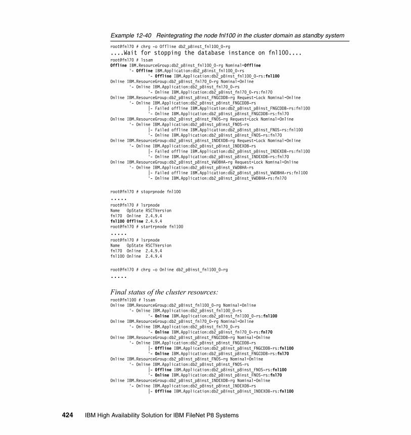
Example 12-40 Reintegrating the node fnl100 in the cluster domain as standby system
root@fnl70 # chrg -o Offline db2_p8inst_fnl100_0-rg....Wait for stopping the database instance on fnl100....root@fnl70 # lssamOffline IBM.ResourceGroup:db2_p8inst_fnl100_0-rg Nominal=Offline '- Offline IBM.Application:db2_p8inst_fnl100_0-rs '- Offline IBM.Application:db2_p8inst_fnl100_0-rs:fnl100Online IBM.ResourceGroup:db2_p8inst_fnl70_0-rg Nominal=Online '- Online IBM.Application:db2_p8inst_fnl70_0-rs '- Online IBM.Application:db2_p8inst_fnl70_0-rs:fnl70Online IBM.ResourceGroup:db2_p8inst_p8inst_FNGCDDB-rg Request=Lock Nominal=Online '- Online IBM.Application:db2_p8inst_p8inst_FNGCDDB-rs |- Failed offline IBM.Application:db2_p8inst_p8inst_FNGCDDB-rs:fnl100 '- Online IBM.Application:db2_p8inst_p8inst_FNGCDDB-rs:fnl70Online IBM.ResourceGroup:db2_p8inst_p8inst_FNOS-rg Request=Lock Nominal=Online '- Online IBM.Application:db2_p8inst_p8inst_FNOS-rs |- Failed offline IBM.Application:db2_p8inst_p8inst_FNOS-rs:fnl100 '- Online IBM.Application:db2_p8inst_p8inst_FNOS-rs:fnl70Online IBM.ResourceGroup:db2_p8inst_p8inst_INDEXDB-rg Request=Lock Nominal=Online '- Online IBM.Application:db2_p8inst_p8inst_INDEXDB-rs |- Failed offline IBM.Application:db2_p8inst_p8inst_INDEXDB-rs:fnl100 '- Online IBM.Application:db2_p8inst_p8inst_INDEXDB-rs:fnl70Online IBM.ResourceGroup:db2_p8inst_p8inst_VWDBHA-rg Request=Lock Nominal=Online '- Online IBM.Application:db2_p8inst_p8inst_VWDBHA-rs |- Failed offline IBM.Application:db2_p8inst_p8inst_VWDBHA-rs:fnl100 '- Online IBM.Application:db2_p8inst_p8inst_VWDBHA-rs:fnl70
root@fnl70 # stoprpnode fnl100.....root@fnl70 # lsrpnodeName OpState RSCTVersionfnl70 Online 2.4.9.4fnl100 Offline 2.4.9.4root@fnl70 # startrpnode fnl100.....root@fnl70 # lsrpnodeName OpState RSCTVersionfnl70 Online 2.4.9.4fnl100 Online 2.4.9.4
root@fnl70 # chrg -o Online db2_p8inst_fnl100_0-rg.....
Final status of the cluster resources:root@fnl100 # lssamOnline IBM.ResourceGroup:db2_p8inst_fnl100_0-rg Nominal=Online '- Online IBM.Application:db2_p8inst_fnl100_0-rs '- Online IBM.Application:db2_p8inst_fnl100_0-rs:fnl100Online IBM.ResourceGroup:db2_p8inst_fnl70_0-rg Nominal=Online '- Online IBM.Application:db2_p8inst_fnl70_0-rs '- Online IBM.Application:db2_p8inst_fnl70_0-rs:fnl70Online IBM.ResourceGroup:db2_p8inst_p8inst_FNGCDDB-rg Nominal=Online '- Online IBM.Application:db2_p8inst_p8inst_FNGCDDB-rs |- Offline IBM.Application:db2_p8inst_p8inst_FNGCDDB-rs:fnl100 '- Online IBM.Application:db2_p8inst_p8inst_FNGCDDB-rs:fnl70Online IBM.ResourceGroup:db2_p8inst_p8inst_FNOS-rg Nominal=Online '- Online IBM.Application:db2_p8inst_p8inst_FNOS-rs |- Offline IBM.Application:db2_p8inst_p8inst_FNOS-rs:fnl100 '- Online IBM.Application:db2_p8inst_p8inst_FNOS-rs:fnl70Online IBM.ResourceGroup:db2_p8inst_p8inst_INDEXDB-rg Nominal=Online '- Online IBM.Application:db2_p8inst_p8inst_INDEXDB-rs |- Offline IBM.Application:db2_p8inst_p8inst_INDEXDB-rs:fnl100
424 IBM High Availability Solution for IBM FileNet P8 Systems

'- Online IBM.Application:db2_p8inst_p8inst_INDEXDB-rs:fnl70Online IBM.ResourceGroup:db2_p8inst_p8inst_VWDBHA-rg Nominal=Online '- Online IBM.Application:db2_p8inst_p8inst_VWDBHA-rs |- Offline IBM.Application:db2_p8inst_p8inst_VWDBHA-rs:fnl100 '- Online IBM.Application:db2_p8inst_p8inst_VWDBHA-rs:fnl70
12.4 Maintenance and upgrade recommendations for DB2
This section contains high-level information about upgrading and maintaining DB2 for FileNet P8 in an HA environment. We discuss the following topics:
� DB2 upgrade for FileNet P8� DB2 maintenance for FileNet P8
For further details about DB2 system maintenance and upgrade, see Chapter 14, “Backup and Recovery” in High Availability, Scalability, and Disaster Recovery for DB2 on Linux, UNIX, and Windows, SG24-7363.
12.4.1 DB2 upgrade for FileNet P8
Your DB2 installation and upgrade are simpler, because the general availability (GA) versions of DB2 V8 on Microsoft Windows platforms and DB2 V9 on UNIX platforms contain the base code for an installation in the downloadable fix pack. This combined fix pack package allows you to install the base code and apply the fix pack in one installation process, saving time and reducing potential errors that might occur during the installation.
DB2 has two types of upgrades: fix pack and version level. We describe both types.
We also provide considerations for upgrading these FileNet P8 components:
� CE, PE, and IS components that use DB2 Server as their metadata repository
� Since IS Version 4.1.2, support for DB2 Version 9.5 as the remote DB failover
DB2 fix pack rolling upgradesA fix pack is a cumulative collection of Authorized Program Analysis Report (APAR) fixes. Fix packs have the following characteristics:
� They are cumulative. Fix packs for a particular release of DB2 supersede or contain all of the APAR fixes that were shipped in previous fix packs and interim fix packs for that release.
Chapter 12. DB2 implementation 425

� They are available for all supported operating systems and DB2 database products.
� They contain multiple APARs.
� They are published on the DB2 Technical Support Web site and are generally available to clients, who have purchased products under the Passport Advantage® program. The DB2 Technical Support Web site is http://www-01.ibm.com/software/data/db2/support/db2_9.
� They are fully tested by IBM.
� They are accompanied by documentation that describes changes to the database products and how to install and remove the fix pack.
HADR gives you high availability while applying DB2 fix packs through rolling upgrades. Your database experiences only momentary downtime while you switch roles between your database servers. With properly written applications using standard retry logic and the proper handling of message SQL30108N if you use Automatic Client Reroute (ACR), there is effectively no loss of data, and no visible downtime to clients.
You follow these steps to perform a rolling upgrade. The HADR Primary database is never taken offline from users:
1. Check your system’s HADR status.2. Apply the fix pack on the standby system.3. Switch the HADR roles from the standby system.4. Apply the fix pack in the old primary system.5. Switch the HADR roles back to the original primary system.
DB2 version upgradeBefore you perform the DB2 upgrade, we recommend that you verify the FileNet P8 components’ compatibility with the DB2 version. See the installation documentation at this Web site:
http://www.ibm.com/support/docview.wss?rs=3278&uid=swg27010422
A rolling upgrade is not supported between DB2 versions or major subversion migrations, such as Version 8.2 to 9.1, or 9.1 to 9.5. For these events, plan for a database outage while the HADR primary database is updated.
The initial critical step of DB2 migrations is running the db2ckmig command, which checks if databases are eligible for migration to the new DB2 version.
For the further details, refer to DB2 9.5 Information Center at:
http://publib.boulder.ibm.com/infocenter/db2luw/v9r5/topic/com.ibm.db2.luw.qb.migration.doc/doc/c0023662.html
426 IBM High Availability Solution for IBM FileNet P8 Systems
Rolling DB2 configuration parametersIn order to keep your HADR systems optimal, apply changes to both servers as quickly as possible.
Note that when updating HADR-specific database configuration parameters, DB2 will not allow you to switch HADR roles. Certain HADR parameters must always remain matched, such as HADR_TIMEOUT, for example. Therefore, you must schedule a required brief database outage while updating the parameters on the primary server and recycling the DB2 instance or deactivating/activating the database.
For the HADR Primary system, this process of role switching is not required for dynamic databases or database manager configuration parameters, that is, which require no recycling of the DB2 database or instance to take immediate effect. When a dynamic database manager or database configuration parameter update has been issued on the HADR primary, you must manually perform the update against the HADR standby, as well. Parameter configurations are not logged, and thus, are not mirrored through HADR log shipping.
For further details, refer to the DB2 9.5 Information Center at:
http://publib.boulder.ibm.com/infocenter/db2luw/v9r5/topic/com.ibm.db2.luw.qb.migration.doc/doc/c0023662.html
12.4.2 DB2 maintenance for FileNet P8
In this section, we describe high-level information about backing up and restoring DB2 databases or tablespaces. Multiple options to backup and restore DB2 exist, depending on your requirements.
DB2 allows offline and online backup of the databases. You also have options to back up the entire database or just incremental changes.
In the following paragraphs, we detail the required steps to perform a database backup for various scenarios. The commands that are shown in this section are run as the database instance owner.
Full offline backupThe easiest way to create a database backup is by using an offline backup. No application is accessing or connected to this database at this time. You can discover whether any application is connected to your database by running this command:
db2 list application for database <database name>
Chapter 12. DB2 implementation 427
You need to stop the CE, PE, and IS applications first. Then, make sure that the connections to the DB2 databases are gone.
To end an application connection from DB2, use the command:
db2 force application <application handle>
To disconnect all the application connections, use:
db2 force application all
The db2 force application all command terminates all of the connections to all of the databases in the DB2 instance. If more than one database is defined in an instance, use this command carefully to not interrupt other applications.
If you want to ensure that no one else is working on DB2, you can optionally stop and restart the DB2 server and put the database in quiesce mode. To force DB2 to end all applications and to not let any of them log on again, use:
db2 quiesce database force connections
Remember, the user must belong to the sysadm or dbadm group.
To create an offline backup of a DB2 database, run:
db2 backup database <database name> to <directory>
To put DB2 back to its normal state, use:
db2 unquiesce db
Full online backupThe advantage of using an online backup is that no application is required to disconnect from the database and no transaction has to be stopped. The database remains accessible and is able to be updated at all times. The online backup also allows you to recover the database to the point in time of the failure. For FileNet P8, there is no need to stop CE, PE, and IS. You typically perform backups when systems need to be highly available and no amount of downtime is acceptable.
Log files are critical for the online backups. Because transactions are still in progress during the backup, the backup might contain the transactions that are in an uncommitted status. DB2 uses the information in the database backup images and the log files to restore the database to a consistent status, as well as to a specified point in time.
To perform an online backup, run this command:
db2 backup database <database name> ONLINE to <directory>
428 IBM High Availability Solution for IBM FileNet P8 Systems
Incremental backupDB2 provides backup facilities for data that has changed since the last offline or online database backup. This feature saves tape or disk space, but it might not reduce the amount of time to perform a backup, because DB2 still needs to read the data blocks to determine if they have changed since the last backup. Performing recovery requires both the database backup and the incremental backups to fully recover the database. Using this method can take more time to recover a database.
Incremental backups are useful for saving space, as well as for saving bandwidth, when backing up over the network.
Backing up and restoring a database with snapshot backupDB2 9.5 provides fully integrated flash copy support. It automates the manual steps that are currently required for backup and restore with flash copy.
Many storage subsystems provide FlashCopy® or snapshot functions that allow you to make nearly instantaneous point-in-time copies of entire logical volumes or data sets.
In a traditional backup or restore operation, the database manager copies data to or from disks using operating system calls. Being able to use the storage subsystems to perform the data copying makes the backup and restore operations much faster. In addition, the impact on the ongoing operation is minimum; therefore, it is an optimal solution for a 24x7 production system.
As of Version 9.5, DB2 provides integrated support for snapshot backups through DB2 Advanced Copy Services (ACS™). DB2 ACS enables you to use the fast copying technology of a storage device to perform the data copying part of backup and restore operations.
Restoring the databaseIt is important to verify the requirements to restore the database, because there are multiple ways to restore a database:
� Based on the amount of time that is needed to recover the database� Recovery based on a specific point in time
Restoring a full database backup is the fastest option. By reapplying database log files, the time that is needed increases; however, you are able to recover to a later point in time. Your strategy truly depends on your requirements.
Chapter 12. DB2 implementation 429

ConsiderationsThere are few considerations for backing up databases for FileNet P8:
� Because FileNet P8 works with multiple databases (in our case, FNGCDDB, FNOS, INDEXDB, and VWDBHA databases), we recommend that you schedule the backup for all databases on your system in the same backup window to maintain consistent data. This consideration is extremely important for the CE Global Configuration Database (GCD) and object store databases (FNGCDDB and FNOS, in this example).
� An offline backup is the preferred method for IBM FileNet P8. An offline backup insures that all application data is in a consistent state. When a restore becomes necessary, all data must be recovered to the same point in time.
430 IBM High Availability Solution for IBM FileNet P8 Systems

Chapter 13. System-level failover testing
In this chapter, we provide the details about failover testing for each of the IBM FileNet P8 components with practical step-by-step procedures in a high availability environment.
We discuss the following topics:
� System-level testing:
– Prerequisites– HTTP servers– Application Engine: Workplace– Content Engine– Content Search Engine– Process Engine server farm– Image Services– Databases
� Actual testing process and results
13
© Copyright IBM Corp. 2009. All rights reserved. 431

13.1 System-level testing
The starting point for the system-level testing is making sure that all servers, the hardware load balancer, and connections are up and running normally. In the case of active/passive clusters, the active node is up and functioning, with the passive node waiting to take over the primary node’s function. The objective of these tests is not to verify full functionality of the software, as in typical quality assurance (QA) testing. Instead, it is to show that service remains available after any one node goes down. It is assumed that the software has passed the QA testing, and therefore, if connectivity is still available after a failure, all functions will operate normally.
In each series of tests, the person executing the test has to authenticate (log on to) to the Application Engine (AE), typically, in the first step of the sequence. For the remaining steps in each sequence, the tester notes whether they are subsequently required to log in to AE again. In certain failover scenarios, we expect that the user will be requested to log on again, while in other failover scenarios, the user’s credentials are retained so that another logon is not required.
In the cases of the HTTP server, AE, Content Engine (CE), and Process Engine (PE), the components within each tier are deployed for high availability in a server farm, with all nodes active (active/active cluster). This configuration is beneficial for scalability, as well as availability, when compared with an active/passive cluster of nodes. Under normal circumstances, all of the nodes in an active/active cluster can be used to service user requests. From a high availability (HA) standpoint, the benefit of this configuration is that there is little, if any, recovery time required after a node failure. The other nodes in the cluster are already up and operational. The only requirement is for the next tier closer to the user to detect the failure and to start directing requests to the remaining nodes. This configuration is the preferred configuration for achieving high availability.
When testing the availability of an active/active cluster in a tier, it is necessary to fail all of the nodes in the cluster one at a time. You must show that the service provided by that cluster remains available regardless of which single node in the cluster fails.
13.1.1 Prerequisites
The prerequisites that we describe here assume that we will test for all of the components that we have set up, including Image Services (IS) and Content Search Engine.
432 IBM High Availability Solution for IBM FileNet P8 Systems
After configuring all of the hardware and software, use a population tool to create an initial set of documents within the Image Services server. These documents must have content (1 KB of random text is sufficient). The intention is to federate them using Content Federated Services for Image Services (CFS-IS) so that they are available through the Content Engine.
Second, use Enterprise Manager to create an object store, enable content-based retrieval (CBR) searches on the Document class, and populate the object store with at least five documents, each containing content. For testing convenience, file these five documents in a single folder. Verify that the documents have been successfully indexed for CBR searches.
Third, configure CFS-IS so that the documents created within the IS system will be federated into the object store. Verify that this operation has completed and that the content of these documents can be accessed through Enterprise Manager.
Each of the following sections details the steps to verify the high availability of each of the component tiers under test. Each test focuses on a specific tier in the configuration. For the system to have end-to-end high availability, each tier must demonstrate that it can continue to provide service in the event of a failure of any single node.
13.1.2 HTTP servers
The two HTTP servers operate as a farm and serve as a front end to the AE systems. They implement WebSphere Application Server-specific load balancing through the use of the HTTP Plug-in. Because both HTTP servers are able to connect to both the AE servers, the loss of either HTTP server does not cause a loss of availability, except for transactions that are in progress at the time of the failure that were directed through the failed node. The hardware load balancer ensures that new connections received from clients will be directed to one or both of the HTTP servers, depending on load and availability. Because testing availability of the hardware load balancer is outside the scope of this book, only a single load balancer is used. We assume the single load balancer is either to be implemented using high availability hardware techniques, or that a backup load balancer is available at all times to be substituted if the primary load balancer fails.
Chapter 13. System-level failover testing 433
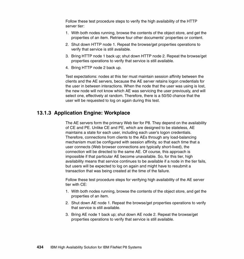
Follow these test procedure steps to verify the high availability of the HTTP server tier:
1. With both nodes running, browse the contents of the object store, and get the properties of an item. Retrieve four other documents’ properties or content.
2. Shut down HTTP node 1. Repeat the browse/get properties operations to verify that service is still available.
3. Bring HTTP node 1 back up; shut down HTTP node 2. Repeat the browse/get properties operations to verify that service is still available.
4. Bring HTTP node 2 back up.
Test expectations: nodes at this tier must maintain session affinity between the clients and the AE servers, because the AE server retains logon credentials for the user in between interactions. When the node that the user was using is lost, the new node will not know which AE was servicing the user previously, and will select one, effectively at random. Therefore, there is a 50/50 chance that the user will be requested to log on again during this test.
13.1.3 Application Engine: Workplace
The AE servers form the primary Web tier for P8. They depend on the availability of CE and PE. Unlike CE and PE, which are designed to be stateless, AE maintains a state for each user, including each user’s logon credentials. Therefore, connections from clients to the AEs through any load-balancing mechanism must be configured with session affinity, so that each time that a user connects (Web browser connections are typically short-lived), the connection will be directed to the same AE. Of course, this approach is impossible if that particular AE become unavailable. So, for this tier, high availability means that service continues to be available if a node in the tier fails, but users will be expected to log on again and might have to resubmit a transaction that was being created at the time of the failure.
Follow these test procedure steps for verifying high availability of the AE server tier with CE:
1. With both nodes running, browse the contents of the object store, and get the properties of an item.
2. Shut down AE node 1. Repeat the browse/get properties operations to verify that service is still available.
3. Bring AE node 1 back up; shut down AE node 2. Repeat the browse/get properties operations to verify that service is still available.
434 IBM High Availability Solution for IBM FileNet P8 Systems

Follow these test steps to verify the functioning of AE with PE:
1. Bring AE node 2 back up. Create a two step workflow from the Process Designer.
2. Shut down AE node 1. Create a two step workflow from the Process Designer.
3. Bring up AE node 1; shut down AE node 2. Create a two step workflow from the Process Designer.
4. Bring up AE node 2. With both nodes running, launch a workflow that contains a manual step.
5. Shut down AE node 1. Complete the manual step in the workflow.
6. Bring up AE node 1; shut down AE node 2. Complete the second step of the workflow.
7. Bring up AE node 2.
13.1.4 Content Engine
Content Engine, along with Process Engine, forms the business logic tier of the P8 architecture. It depends primarily upon the availability of the databases, File Storage Areas, and or Fixed Content Devices for its operation. For CE to be highly available, each of these underlying services must be made to be highly available also, along with other infrastructure, such as the network.
CE is configured for high availability in an active/active server farm. CE is designed to be stateless, so that requests can be sent to any CE within the farm for processing. Clients of CE will access it in one of two ways. Web Services clients will connect through a load balancer (a hardware load balancer in the configuration that is used for this book). Enterprise JavaBeans (EJB) clients will use software load balancing that is provided by the application server (WebSphere Workload Manager, in the case of WebSphere Network Deployment Edition, the application server that is used for this book).
Because all CEs are normally active, testing of high availability in this tier will involve shutting down each node in the tier in turn and verifying availability of the CE service at all times. Because CEs are stateless and do not “replace” the functioning of a failed node, no failovers or failbacks are required, only verifying that service remains available regardless of which CE node might be down at a given time.
Chapter 13. System-level failover testing 435

Follow these test procedure steps for verifying the high availability of Content Engine:
1. With all nodes running, log in to Workplace from a browser. Create a document with content. Browse the contents of the object store. Get the properties of a document.
2. Shut down CE node 1. Check out the document that was created in step 1.
3. Bring up CE node 1; shut down CE node 2. Check in the document that was checked out in step 2, with new content.
4. Bring CE node 2 back up.
As noted earlier, the EnableDispatcher setting in Content Engine to enable the dispatching of indexing jobs to Content Search Engine (CSE) constitutes a single point of failure in versions of the 4.x CE prior to 4.5. In those earlier versions, including Version 4.0.1, which is used for the testing for this book, it is necessarily to change this setting manually when a failover occurs, if indexing is to continue.
13.1.5 Content Search Engine
Content Search Engine consists of several components, and of those components, three form single points of failure:
� The Master Administration Server: There is only one Master Administration Server within a K2 domain. For high availability, it must be active/passive-clustered.
� The Index Server: For a given collection, there is only one Index Server. Furthermore, this server must have local file access, typically through a Fibre Channel connection to a storage area network (SAN) device. For high availability, each Index Server must therefore be active/passive-clustered.
� The CE that dispatches indexing jobs: In CE Versions 4.0.0 and 4.0.1, there is a distinguished CE node that performs this function. For a completely automatic failover if this node were to fail, either it must be active/passive-clustered, or the cluster management software must run a custom program that will change the EnableDispatcher setting from the failed node to another node in the farm.
In the configuration of P8 that is used for this book, all of the CSE services are deployed on one logical partition (LPAR). Consequently, that LPAR is active/passive-clustered with another LPAR that is using IBM PowerHA for AIX (HACMP - formerly IBM High Availability Cluster Multi-Processing). Therefore, testing consists of shutting down the initially active node, verifying that a failover occurs, and then, that service remains available. We also want to verify that
436 IBM High Availability Solution for IBM FileNet P8 Systems

Content Engine will continue to accept new documents even when the service is completely unavailable.
Follow these test procedure steps for verifying the high availability of the Content Search Engine:
1. With all nodes running, log in to Workplace from a browser. Create a new document containing at least one keyword that is not contained in any other document in the repository. Wait until all of the documents have been indexed (set a low dispatcher wait interval, and check the indexing job queue to verify that the indexing has completed).
2. Create a new document with content.
3. Verify that the document is indexed and can be found in a search.
4. Shut down CSE node 1 and verify that a failover to node 2 has occurred. Perform the same test as in steps 2 and 3.
5. Perform a failback from node 2 back to node 1. Perform the same test as in steps 2 and 3.
6. Now, bring down both nodes, so that the CSE service is unavailable. Perform the same test as in step 2.
7. Finally, restore node 1 to normal operation. Now, perform the test in step 3 to verify whether the documents that were created in step 6 have been indexed now that service has been restored.
We expect that in step 6, the user will still be able to create a document, and that this document will be indexed and be searchable after the CSE nodes are brought back up in step 7.
13.1.6 Process Engine server farm
Two high availability configurations of Process Engine can be set up: either active/active server farm or active/passive cluster. For this book, we test the best practice approach, which is the active/active server farm of PEs. In this configuration, testing of its high availability is similar to the previous tests for the Content Engine server farm. Because either node in the farm must be able to handle all client requests, the tests involve alternately shutting down one or the other of the PEs in the farm, and while each node is down, performing a client operation through AE to demonstrate that users still have service during the outage.
Chapter 13. System-level failover testing 437

Starting with both Process Engines in the active state, execute the following tests for verifying high availability of Process Engine:
1. Shut down PE node 1. Launch a workflow process that contains a manual intervention step.
2. Bring up PE node 1; shut down PE node 2. Complete the manual intervention step in the previously launched workflow process.
3. Bring PE node 2 back up. Complete the work item for the launched workflow with both nodes up.
4. Shut down PE node 2. Launch a workflow process with a manual intervention step.
5. Bring PE node 2 back up; shut down PE node 1. Complete the manual intervention step in the launched workflow.
6. Bring PE node 1 back up. Complete the work flow with both nodes up.
13.1.7 Image Services
In the configuration that is used for this book, we used the Image Services system as a Fixed Content Device by Content Engine. The IS system is, in turn, a client of the database. Because the IS system is configured for high availability in an active/passive cluster, only a single failover is required to test the system’s HA robustness. If the IS system can fail over to the passive node, and if Content Engine can then continue to function by accessing content stored in IS, the test is successful. We have already verified that the documents within the IS system are available through Content Engine in the prerequisite steps just listed.
Use the following test procedure for verifying high availability of Image Services:
1. Shut down the active IS system. Verify that failover occurs and that HACMP brings up the passive node.
2. Verify that CE users can still access content that is stored in the IS system.
3. Perform a failback from the passive IS node to the originally active IS node.
4. Verify that CE users can still access content that is stored in the IS system.
In addition to these tests that verify that the IS system is highly available as a fixed content device through Content Engine, we also verify that the IS system remains available for its native clients:
1. Verify that the IS system is available from the IDM Desktop client by logging in and retrieving a document image.
2. Shut down the active IS system (node 1). Verify that failover occurs and that HACMP brings up the passive node (node 2).
438 IBM High Availability Solution for IBM FileNet P8 Systems
3. Verify that the IS system is available from the IDM Desktop client by logging in and retrieving a document image. Note whether the user must reconnect or log on again.
4. Shut down node 2, and verify that HACMP brings the node 1 IS system back up.
5. Verify that the IS system is available from the IDM Desktop client by logging in and retrieving a document image. Note whether the user must reconnect or log on again.
13.1.8 Databases
Because we are using the DB2 High Availability Disaster Recovery (HADR) feature in the configuration for this book, database failover is invisible to the P8 servers (the database clients). In our test environment, all of the databases reside in a single instance of DB2. Therefore, failover testing involves shutting down the active node and observing that failover and continuity occur successfully. In the preceding tests, we have verified that the primary database is operating properly with all of its clients, so we can proceed directly to the failover testing:
1. Shut down the primary DB server.
2. Verify that failover occurs so that the passive database is brought fully online.
3. Verify that CE users can access content that is stored both in the filestore and in the IS system.
4. Use the Process Tracker to complete a work item for a launched workflow.
5. Perform a failback from the passive database node to the original active node.
6. Verify that CE users can access content that is stored both in the filestore and in the IS system.
7. Use the Process Tracker to complete a work item for a launched workflow.
13.2 Actual testing process and results
For Content Search Engine, refer to Chapter 10, “Content Search Engine implementation” on page 221, and for Image Services, refer to Chapter 11, “Image Services implementation” on page 285 for details about tests and test results. System-level failover tests involve more than one component so many P8 components are tested together under the same configuration.
Chapter 13. System-level failover testing 439

For example, CE and PE are tested together for these reasons:
� They are dependent on each other for workflow.� Workplace is the application that we use to test both engines.
13.2.1 HTTP servers
When both HTTP servers are running, client requests are spread across both of them. Figure 13-1 shows a functioning FileNet Workplace Web application, beneath which, two side-by-side command windows show the entries for the two HTTP logs, one for each server. In this case, both servers are serving HTTP GET requests successfully (that is, code 200).
Figure 13-1 Both HTTP servers are running
We stop one of the HTTP servers by using the WebSphere administrative console, as shown in Figure 13-2 on page 441.
440 IBM High Availability Solution for IBM FileNet P8 Systems
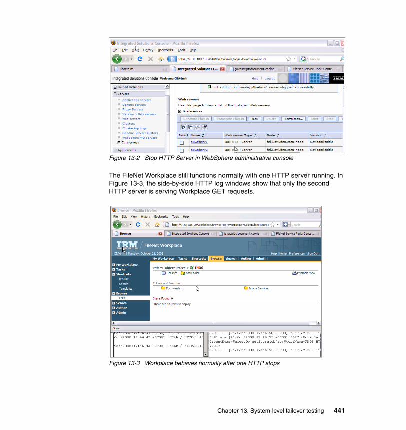
Figure 13-2 Stop HTTP Server in WebSphere administrative console
The FileNet Workplace still functions normally with one HTTP server running. In Figure 13-3, the side-by-side HTTP log windows show that only the second HTTP server is serving Workplace GET requests.
Figure 13-3 Workplace behaves normally after one HTTP stops
Chapter 13. System-level failover testing 441
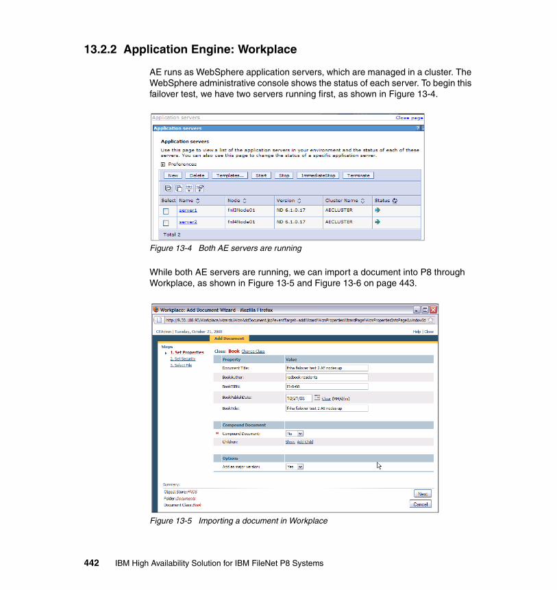
13.2.2 Application Engine: Workplace
AE runs as WebSphere application servers, which are managed in a cluster. The WebSphere administrative console shows the status of each server. To begin this failover test, we have two servers running first, as shown in Figure 13-4.
Figure 13-4 Both AE servers are running
While both AE servers are running, we can import a document into P8 through Workplace, as shown in Figure 13-5 and Figure 13-6 on page 443.
Figure 13-5 Importing a document in Workplace
442 IBM High Availability Solution for IBM FileNet P8 Systems
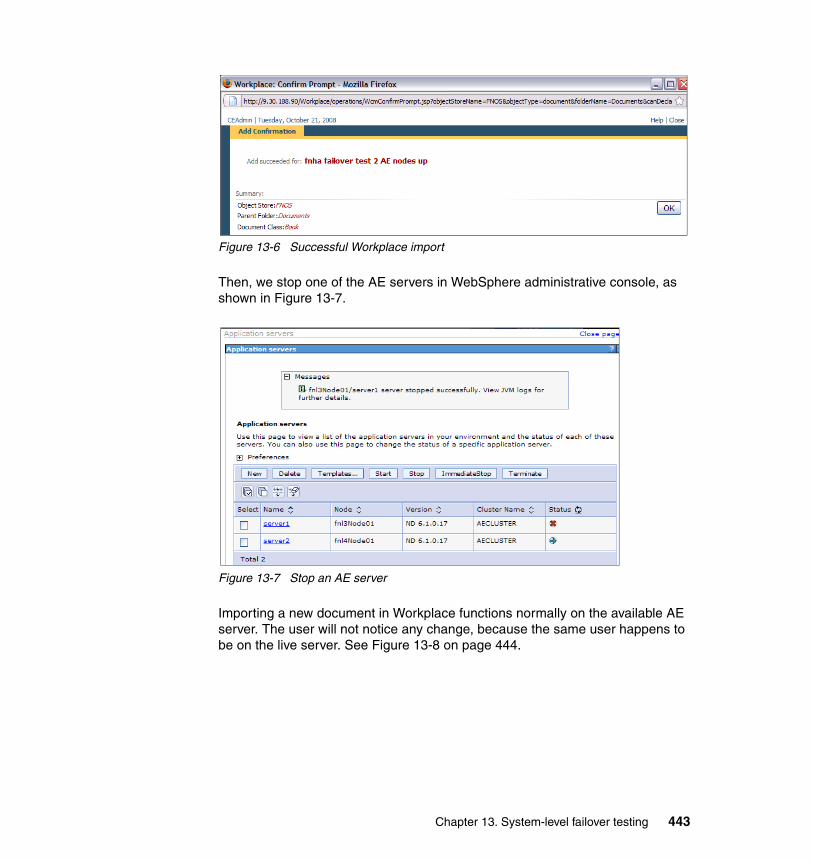
Figure 13-6 Successful Workplace import
Then, we stop one of the AE servers in WebSphere administrative console, as shown in Figure 13-7.
Figure 13-7 Stop an AE server
Importing a new document in Workplace functions normally on the available AE server. The user will not notice any change, because the same user happens to be on the live server. See Figure 13-8 on page 444.
Chapter 13. System-level failover testing 443
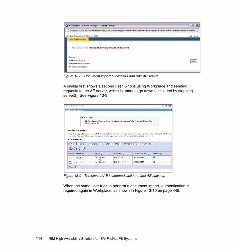
Figure 13-8 Document import successful with one AE server
A similar test shows a second user, who is using Workplace and sending requests to the AE server, which is about to go down (simulated by stopping server2). See Figure 13-9.
Figure 13-9 The second AE is stopped while the first AE stays up
When the same user tries to perform a document import, authentication is required again in Workplace, as shown in Figure 13-10 on page 445.
444 IBM High Availability Solution for IBM FileNet P8 Systems
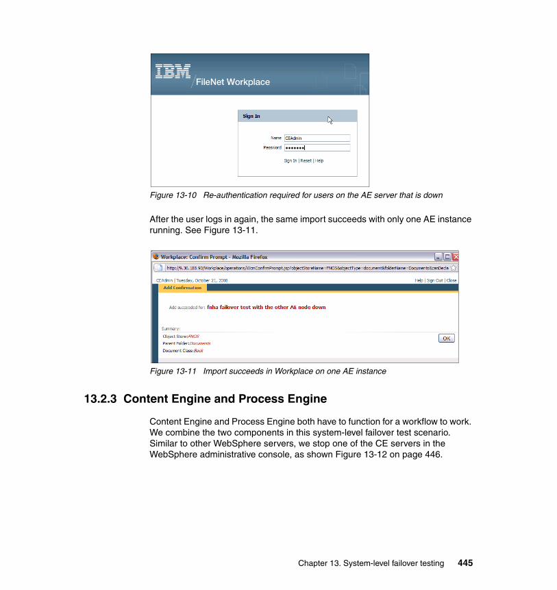
Figure 13-10 Re-authentication required for users on the AE server that is down
After the user logs in again, the same import succeeds with only one AE instance running. See Figure 13-11.
Figure 13-11 Import succeeds in Workplace on one AE instance
13.2.3 Content Engine and Process Engine
Content Engine and Process Engine both have to function for a workflow to work. We combine the two components in this system-level failover test scenario. Similar to other WebSphere servers, we stop one of the CE servers in the WebSphere administrative console, as shown Figure 13-12 on page 446.
Chapter 13. System-level failover testing 445
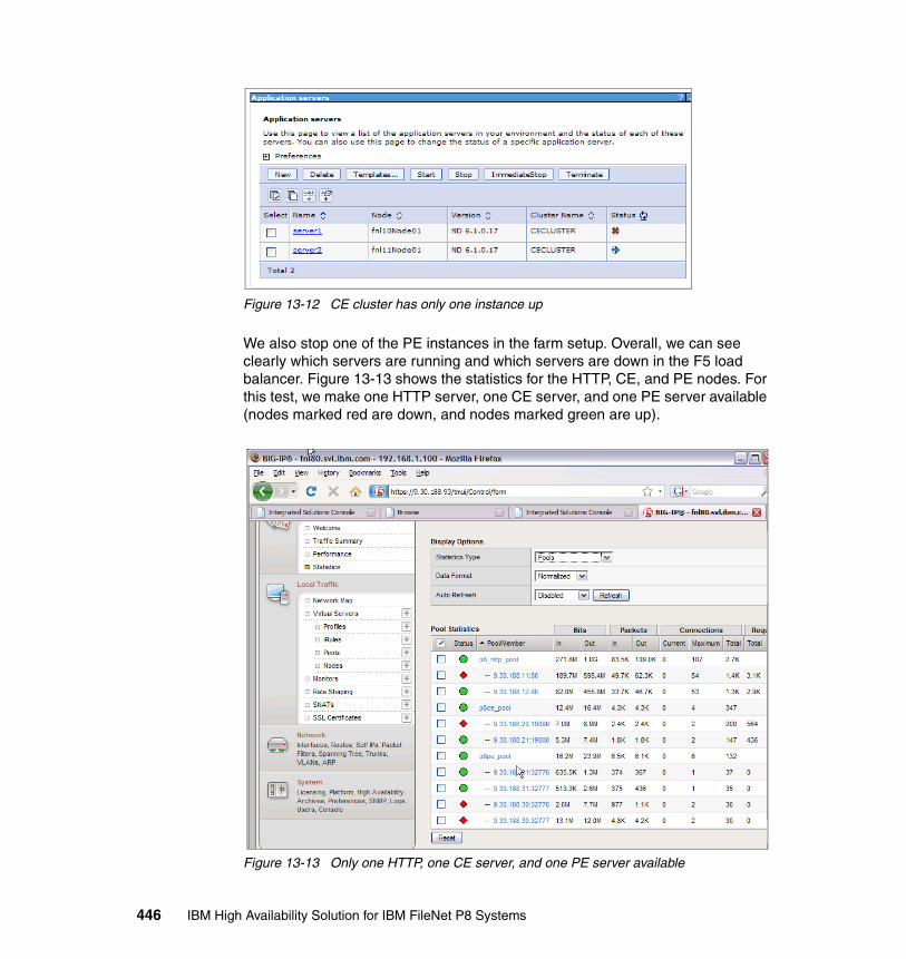
Figure 13-12 CE cluster has only one instance up
We also stop one of the PE instances in the farm setup. Overall, we can see clearly which servers are running and which servers are down in the F5 load balancer. Figure 13-13 shows the statistics for the HTTP, CE, and PE nodes. For this test, we make one HTTP server, one CE server, and one PE server available (nodes marked red are down, and nodes marked green are up).
Figure 13-13 Only one HTTP, one CE server, and one PE server available
446 IBM High Availability Solution for IBM FileNet P8 Systems
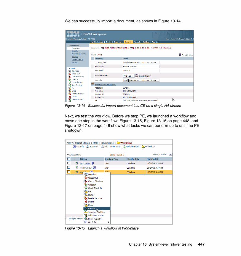
We can successfully import a document, as shown in Figure 13-14.
Figure 13-14 Successful import document into CE on a single HA stream
Next, we test the workflow. Before we stop PE, we launched a workflow and move one step in the workflow. Figure 13-15, Figure 13-16 on page 448, and Figure 13-17 on page 448 show what tasks we can perform up to until the PE shutdown.
Figure 13-15 Launch a workflow in Workplace
Chapter 13. System-level failover testing 447
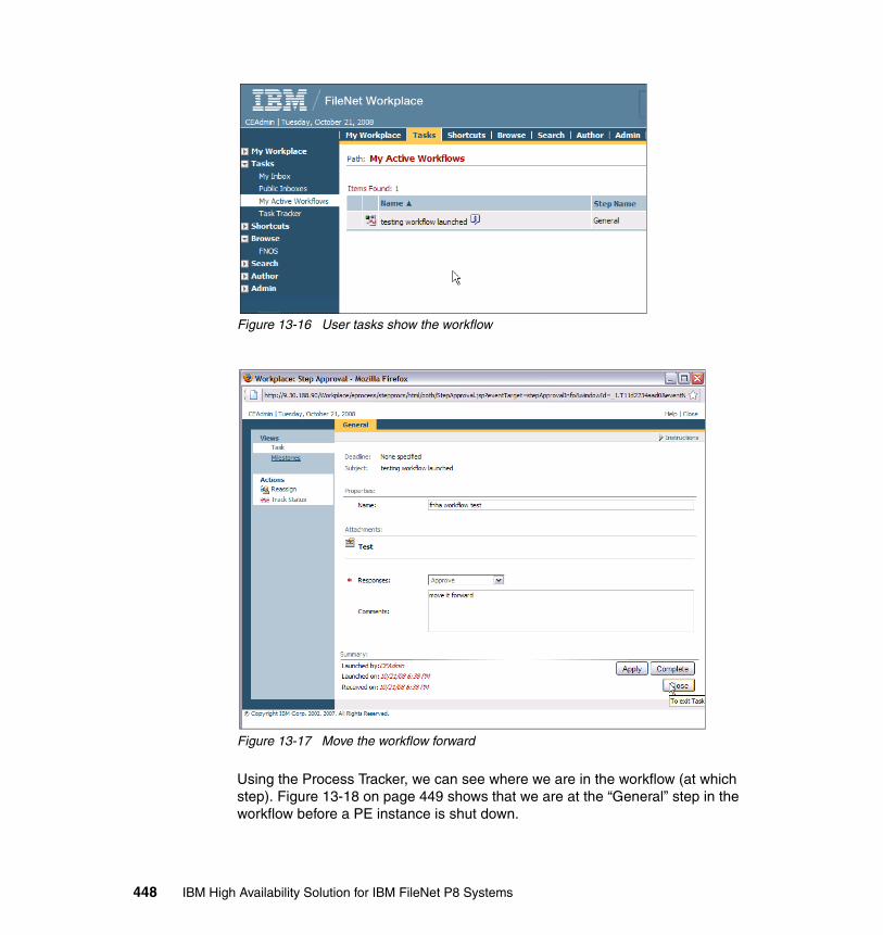
Figure 13-16 User tasks show the workflow
Figure 13-17 Move the workflow forward
Using the Process Tracker, we can see where we are in the workflow (at which step). Figure 13-18 on page 449 shows that we are at the “General” step in the workflow before a PE instance is shut down.
448 IBM High Availability Solution for IBM FileNet P8 Systems
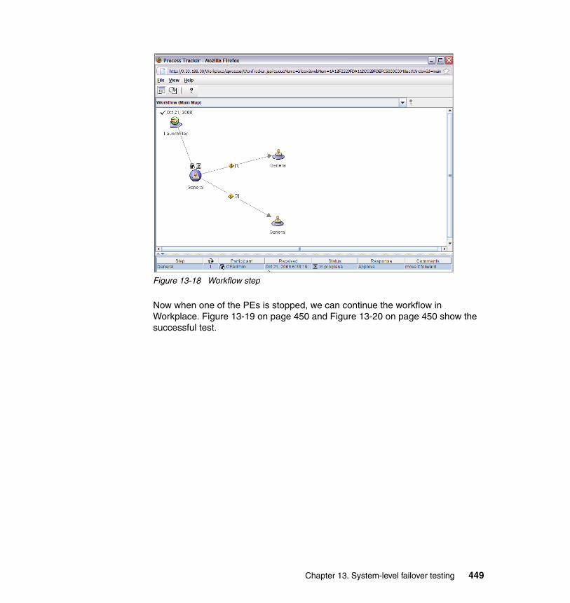
Figure 13-18 Workflow step
Now when one of the PEs is stopped, we can continue the workflow in Workplace. Figure 13-19 on page 450 and Figure 13-20 on page 450 show the successful test.
Chapter 13. System-level failover testing 449
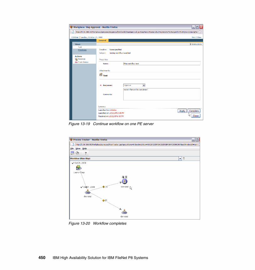
Figure 13-19 Continue workflow on one PE server
Figure 13-20 Workflow completes
450 IBM High Availability Solution for IBM FileNet P8 Systems
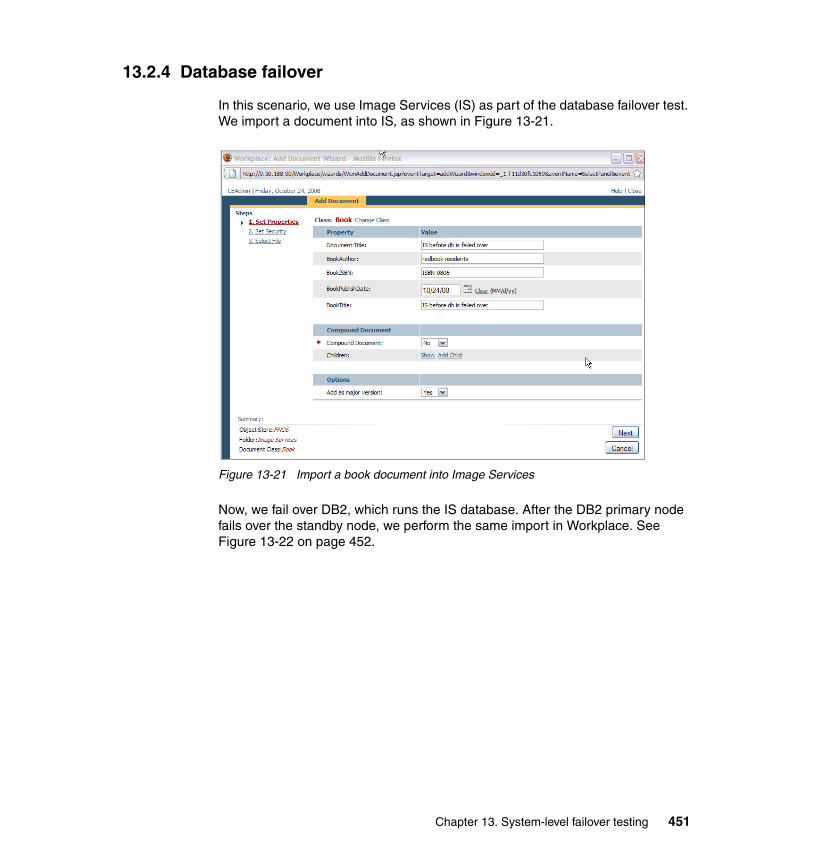
13.2.4 Database failover
In this scenario, we use Image Services (IS) as part of the database failover test. We import a document into IS, as shown in Figure 13-21.
Figure 13-21 Import a book document into Image Services
Now, we fail over DB2, which runs the IS database. After the DB2 primary node fails over the standby node, we perform the same import in Workplace. See Figure 13-22 on page 452.
Chapter 13. System-level failover testing 451
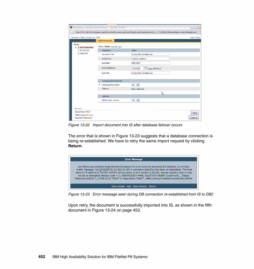
Figure 13-22 Import document into IS after database failover occurs
The error that is shown in Figure 13-23 suggests that a database connection is being re-established. We have to retry the same import request by clicking Return.
Figure 13-23 Error message seen during DB connection re-established from IS to DB2
Upon retry, the document is successfully imported into IS, as shown in the fifth document in Figure 13-24 on page 453.
452 IBM High Availability Solution for IBM FileNet P8 Systems

Figure 13-24 Successful import in IS after DB failover
Chapter 13. System-level failover testing 453

454 IBM High Availability Solution for IBM FileNet P8 Systems
Related publications
The publications listed in this section are considered particularly suitable for a more detailed discussion of the topics covered in this book.
IBM Redbooks publications
For information about ordering these publications, see “How to get IBM Redbooks publications” on page 457. Note that several of the documents referenced here might be available in softcopy only:
� IBM Content Manager Backup/Recovery and High Availability: Strategies Options and Procedures, SG24-7063
� IBM TotalStorage Solutions for Disaster Recovery, SG24-6547
� WebSphere Application Server V6 System Management & Configuration Handbook, SG24-6451
Other publications
These publications are also relevant as further information sources:
� IBM FileNet P8 System Overview, GC31-5482
� IBM FileNet P8 High Availability Technical Notice, GC31-5487
� IBM FileNet 4.0 Installation and Update Guide, GC31-5488
� IBM FileNet Image Services, Version 4.1, Microsoft Cluster Server Installation and Upgrade Procedures for Windows Server, GC31-5531-01
� IBM FileNet Image Services, Version 4.1, VERITAS Cluster Server and VERITAS Volume Replicator Guidelines, GC31-5545
� IBM FileNet Image Services, Version 4.1, Installation and Configuration Procedures for AIX/6000, GC31-5557-01
� IBM FileNet Image Services, Version 4.1, Release Notes, GC31-5578-03
� IBM FileNet P8 Content Federation Services for Image Services, Version 4.0, Guidelines, GC31-5484-01
� IBM FileNet Image Services, ISRA, and Print Hardware and Software Requirements, GC31-5609-04
© Copyright IBM Corp. 2009. All rights reserved. 455
� IBM FileNet Image Services, OSAR Cable Tool, 2008-07-22
� High Availability, Scalability, and Disaster Recovery for DB2 on Linux, UNIX, and Windows, SG24-7363
Online resources
These Web sites are also relevant as further information sources:
� Product documentation for IBM FileNet P8 Platform:
http://www.ibm.com/support/docview.wss?rs=3278&uid=swg27010422
� Product documentation for IBM FileNet Image Services:
http://www.ibm.com/support/docview.wss?rs=3284&context=SSNVUD&uid=swg27010558
� IBM PowerHA for AIX or IBM High Availability Cluster Multi-Processing (HACMP) library:
http://publib.boulder.ibm.com/infocenter/clresctr/vxrx/index.jsp?topic=/com.ibm.cluster.hacmp.doc/hacmpbooks.html
� DB2 Information Center:
http://publib.boulder.ibm.com/infocenter/db2luw/v9r5/index.jsp
� DB2 database product documentation:
http://www.ibm.com/support/docview.wss?rs=71&uid=swg27009474
� Migration to DB2 Version 9.5:
http://publib.boulder.ibm.com/infocenter/db2luw/v9r5/topic/com.ibm.db2.luw.qb.migration.doc/doc/c0023662.html
� IBM DB2 Version 9 system requirements:
http://www.ibm.com/software/data/db2/9/sysreqs.html
� BIG-IP System Management Guide:
https://support.f5.com/kb/en-us/products/big-ip_ltm/manuals/product/bigip9_0sys.html
� Instructions for BIG-IP 5 high availability configuration in the GUI:
https://support.f5.com/kb/en-us/products/big-ip_ltm/manuals/product/bigip9_0sys/9_0_xSystemMgmtGuide-13-1.html#wp1020826
456 IBM High Availability Solution for IBM FileNet P8 Systems

How to get IBM Redbooks publications
You can search for, view, or download IBM Redbooks publications, IBM Redpaper publications, Technotes, draft publications and Additional materials, as well as order hardcopy IBM Redbooks publications, at this Web site:
ibm.com/redbooks
Help from IBM
IBM Support and downloads
ibm.com/support
IBM Global Services
ibm.com/services
Related publications 457

458 IBM High Availability Solution for IBM FileNet P8 Systems

Index
Symbols.Net API 26
Aabsolute path 363access control list 22access role 115ACL 22active cluster node 360active database 382active node 153, 374active/active
cluster 46farm 204, 207
active/passivecluster 50, 204
active-activeconfiguration 18
active-passiveconfiguration 18HA cluster 286
addNode.sh command 139, 158address space 82administration tools 152administrative console 81, 138, 157, 163, 445administrative partition 114administrative security 138, 157administrative task 355aixterm 330algorithm 48algorithms 204alternate IP configuration 378annotation 222APAR 425API based program 152applets 29applheapsz 395application clustering 10application data 204application failure 352application load 153application monitor log 368application server 21, 157
© Copyright IBM Corp. 2009. All rights reserved.
application server definition 137application tier 14–15applications server 140, 158approval process 120asymmetric cluster 286asynchronous 377authentication information 39automatic client reroute 375availability 11
measuring 7availability level 9
Bbackup 5, 427backup mode 328backup system 373bandwidth 429basic availability test 214bes_commit 332BLOB 394boot time 314broadcast 18broadcast domain 81broker server 53browsers 102bus length 339business activity monitoring 20business impact 11business intelligence 63business logic 15business logic tier 14business process 26, 204business process framework 20business-centric 20business-critical nature 286
Ccach response 23Capture 20catalog 208catalog tcpip node 208CBR 222CBR-enabled string property 222
459

cell 137, 157CFS 22chvg command 302cl_scdiskreset command 340classify 222cldisp 296client access 370, 378client communication 381client configuration 385client instance 207client tier 14–15client updater 212clstat 343clstat command 366cluster domain 409, 420cluster information daemon 366cluster manager daemon log 368cluster node 357, 402cluster status 422clustering 10cluster-single point of control 298collection 37, 222collection file 52COM API 26command line 332committed transaction 375communicates 205communication daemon 368compliance requirement 21component integrator 28configuration editor 336connectivity 432console interface 79container-managed authentication 164Content Based Retrieval 36content based retrieval 222, 253content based search 222content element 21Content Engine
communication protocol 25EJB API 26high availability 22scalability 22transport protocol 25Web Services API 26
Content Engine database 21Content Engine Web Services (CEWS) 25content federated service 22content management 78
Content Search Engine 222continuous availability 12cookie 90cor_listen 332corporate governance standards 120cross repository Search 36C-SPOC 298ct_management_scope 403custom object 152custom permission_table 363Customer-developed application 20
DDARE synchronization log 368data file 357data redundancy 10data replication protection 378data table space 372data tier 14–15database backup 429database code
rolling upgrade 379database configuration parameter 395database engine 375database failure 289database instance 378database manager 370database manager system 15database operation 382database pair 378database server 207, 370database server resource 373database structure 25data-centric 17data-link layer 74db2_kill command 413db2haicu 370, 401db2pd 400db2pd command 404, 414decryption 47default gateway 403default service 85demand 331demilitarized zone 78dependency relationship 422deploy manager 139, 157deployment manager definition 156devreset command 340
460 IBM High Availability Solution for IBM FileNet P8 Systems

directory server 138, 157disaster recovery 10disaster recovery strategy 10disk array 17Disk controller failure 289Disk failure 289disk redundancy 9disk resources 373disk subsystem 8dispatcher 52document
versioned 22document catalog 21document management 120document review 120domain configuration 22down time 6ds_init 332dual-server IS 291dynamic logical partitioning 64
EECM 152eForms 20, 30EJB 48EJB API
Content Engine 26EJB transport 26
advantages 26electronic 30email management 20encryption 47end-to-end solution 5Engine-init.war 164enhance concurrent capable volume group 301Enterprise Content Management 20, 152Enterprise Java Beans (EJB) 25enterprise resource planning 63enterprise user 204equivalency 383errorlog 368event processing 22event script log 368external storage infrastructure 62external user 204
Ffailback 18
failover 10, 17, 46, 222, 375, 378Farming 10fastest mode 84fault tolerance 223federation
benefit 22definition 22
File Collection 362file system 21, 208, 222, 292, 374firewall 8, 47firewall process 16fixed content device 35fixed-content device 21flash copy 429fn_edit 316fn_util 317from 370full database backup 429full text indexing 36
GGCD JNDI 161get dbm cfg 399Global Configuration Data (GCD) 22global configuration database 371grid computing 65group services log file 368
HHACMP cluster 337HADR_LOCAL_SVC 399HADR_PEER_WINDOW 398HADR_REMOTE_SVC 399halt 414hardware load balancer 209hardware-only solution 5health monitor 87, 91, 114heartbeat 403high availability 4, 10–12high availability strategy 370high availibility 223High-density 24-inch 64home directory 384horizontal scalability 120, 223horizontal scaling 4hot-standby 376http 91HTTPS traffic 47
Index 461
IIBM FileNet Records Manager 20idle standby 286IDM Find query 341ifconfig command 414ifconfig down command 421image manager component 286inactive cluster node 328incremental backups 429index areas 37index table space 372Indexing 222indexing request 222inetd 306information abstraction 40initfnsw 330initfnsw command 355, 367initfnsw status 343initial configuration 403installation action step 389installation directory 156, 390installation kit 384instance crash 413internal terminator 339intial boot sequence 209IP address 374, 378IP address space 80IP alias 299IP routing 74IP sprayer 8IP-based cluster 10ISTK 330
JJava API Assembly 209Java applet 134JFS log 304
KK2 Administration Server 39K2 Broker Server 41K2 Index Server 40K2 Master Administration Server 39K2 Search Server 41K2 Ticket Server 39kernel 305key functional component 370key pair 402
killfnsw 330
LLAN 80LDAP authentication 120least connection 84legacy system 22Lightweight Directory Access Protocol (LDAP) 23listening mode 204load balancer 8, 47, 153, 209, 446load balancing 10load balancing method 84load balancing pool 114load-balanced server farm 46local area network 80local file access 40local host 402localization 30log buffer 377log files 375, 377log shipping 427logical container 114logical partitions 376logical subset 80logical tiers
Content Manager 14logical volume 292, 357logon credential 48, 434lssam command 411, 414
Mmagnetic storage 32magnetic storage and retrieval 286, 291managed node 123master administration server 39matrix
availability 6members 84memory-intensive 64metadata 22, 152, 371micro-partitioning 64minor number 317mk_links 317MKF 317, 357, 371monitor interval 333monitor script 331monitors 209mount -a command 303
462 IBM High Availability Solution for IBM FileNet P8 Systems

MSAR 286, 291multi-keyed file 317, 357, 371
Nnatural disasters 5NCH_daemon 332near-synchronous 377netmask 82netmon.cf file 403network adapter failure 289Network Attached Storage (NAS) 21network clearing house database 293Network Clearinghouse domain 209network communication 44network devices 84network equivalency 422network failure 289network infrastructure 62network load balancer 44network maintenance task 81network performance 74network resource 373, 378network setting 209node 91node agent 123node availability test 214nodes 114non-logged operation 380NTP server 402
Oobject store 22, 371offline backup 427offline database backup 397offline status 411online backup 428online status 411optical library 337, 340optimum availability investment point 11OSAR 291outage 4ownership 374
Ppage cache 332parallel querying 41, 222partner 204
passive node 153, 204passive role 382passphrase 402password 160passwordless ssh 403peer domain scope 403peer state 404performance
Content Engine, transport 26persistence 90persistence method 84physical database 373physical machine 4physical storage area 371ping response 218planned downtime 286planned outage 5platform clustering 10policy script 383pool 84port number 87, 382Power failure 289PPM configuration 363preprpnode command 403presentation layer 29, 134presentation tier 14–15primary 370primary node 413, 451primary nodes 402primary role 378, 413private network 381, 421process 204process analyzer 20process broker services 95process designer 435process simulator 20process tracker 448processing power 64processing-centric 17processor cycle 64process-related data 371profile 140, 158, 363profile definition 156property 90, 211protocol 44, 74, 87public host key 402public interface 423public network 381
Index 463

Qquality assurance 432
RRAID system 21raw device 317, 357, 374raw partition 208, 302Redbooks Web site 457
Contact us xvredundant circuits 289redundant network infrastructure 289region recovery 372register 409relationship 383remote clustered database 290remote command execution 402remote content management system 22remote procedure call 205rendition engine 20replication 10resource group 360, 383response
caches 23response file 389restore 397, 427retention period 30retry logic 426rich media 120rmsock 307rolling upgrade 426
database code 379
Sscp command 397scripts 374SCSI 338SCSI adapter 338SCSI bus 338search 222search operation 222secure communication 47secure shell (ssh) 402security 47, 123security breaches 5security definition 156security zone 120self IP address 82server cluster 17
server failure 289server farm 16service address 299service name 85Service Oriented Architecture 48session affinity 48, 90, 102, 434shared file system 335Shared processor pool 64Shared storage 286shared storage 372shared volume group 301Sharepoint Connector 29single point of failure 44, 47, 288single points of failure 223snapshot 429SOA 48software failure 5source database 370SPOC command log 368SPOF 288SQL30108N 426ssh 402ssh command 403ssh-keyscan utility 402SSL security 29standby node 316, 341start script 363startup context page 101statefull session bean 49stateless 434stateless bean 49sticky session 48stop script 329, 356storage 376storage area 371Storage Attached Network (SAN) 21storage device 429storage library 337storage subsystem 44, 429storage tier 14strategy 223subsystem 204surface file 293svcename 399symbolic link 363symmetric multiprocessing 63synchronous 377system maintenance 355system object 114
464 IBM High Availability Solution for IBM FileNet P8 Systems

system operator errors 5
Ttable space 427takeover 341target database 370technology direction 18terminators 338throughput 49TM_daemon 332topology 368trace log 368traffic management 122traffic management system 80transaction processing 63transactions 377transfer remote procedure 205transferred workflow 205transport protocol 48
Content Engine 25typical install 388
Uultra high performance computing 63umask 227UpdateInstaller 156uptime 6user account 114user authentication 23user name 160user-defined action 22utility log 368
VVerity Query Language 36version
document 22vertical scalability 4virtual address 88, 411virtual I/O 64virtual IP 378virtual IP name 210virtual LAN 64virtual local area network 66, 74, 122virtual name 209virtual port 88virtual server 88, 114, 209
virtualization 291VLAN 74volume group 226, 292, 357vwbroker 95vworbbroker 95
WWcmApiConfig.properties 143Web content publishing 120Web server 78, 120Web Services API
Content Engine 26Web services interface 25wizard-driven content contribution 120workflow 204, 445workflow management 79workflow object 152workload 205Workplace 120workplace application 78WSI 25, 48WSI transport 49
advantages 26
XXML 120
Index 465

466 IBM High Availability Solution for IBM FileNet P8 Systems

(1.0” spine)0.875”<
->1.498”
460 <->
788 pages
IBM High Availability Solution
for IBM FileNet P8 System
s


®
SG24-7700-00 ISBN 0738433268
INTERNATIONAL TECHNICALSUPPORTORGANIZATION
BUILDING TECHNICALINFORMATION BASED ONPRACTICAL EXPERIENCE
IBM Redbooks are developed by the IBM International Technical Support Organization. Experts from IBM, Customers and Partners from around the world create timely technical information based on realistic scenarios. Specific recommendations are provided to help you implement IT solutions more effectively in your environment.
For more information:ibm.com/redbooks
®
IBM High Availability Solutionfor IBM FileNet P8 Systems
Provides HA strategies and options for IBM FileNet P8 systems
Includes HA implementation for Content Engine, Process Engine, and Application Engine
Describes HA implementation for Content Search Engine, Image Services, and databases
Many organizations require almost continuous availability of their mission-critical, IBM FileNet P8 systems. Loss of system resources and services can translate directly into lost revenue and lost customers. The goal, therefore, is to design and implement IBM FileNet P8 systems that are highly available by compensating for both planned and unplanned system outages and eliminating single points of failure.
IBM FileNet P8 Platform provides availability features that are built-in to the core components. With these features, high availability of an IBM FileNet P8 system can be achieved through redundancy: redundant components, redundant systems, and redundant data. Hardware and software components might fail. With redundancy, the failure can be eliminated or minimized.
This IBM Redbooks publication describes strategies and options for core IBM FileNet P8 system components. In addition, the book provides detailed, step-by-step procedures that we used to implement high availability for our case study IBM FileNet P8 system. This book serves as a practical reference when you design and implement highly available IBM FileNet P8 systems.
This book is intended for IT architects, IT specialists, project managers, and decision makers identifying the best high availability strategies and integrating them into the IBM FileNet P8 system design process.
Back cover