hi-tech components
TRANSCRIPT

HI-TECH COMPONENTS
ORBITAL WELD AND METAL GASKET FACE SEAL FITTINGS
HI-TECH COMPONENTS
TECHNICAL INFORMATION
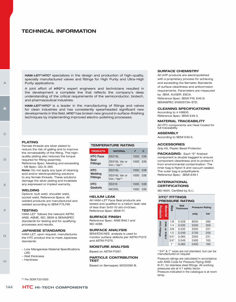
HELIUM LEAK All HAM-LET Face Seal products are tested and qualified to a helium leak rate of less than 3x10⁻¹⁰ std cm3/sec.Reference Spec: SEMI F1.
SURFACE FINISH Reference Spec: ANSI B46.1 and ISO 4288.
SURFACE ANALYSIS SEM/EDX/AES analysis is used to monitor surface defects per ASTM F1372 and ASTM F1375.
MOISTURE ANALYSIS
Based on ASTM F1397.
PARTICLE CONTRIBUTION TEST
Based on Semaspec 90120390 B.
SURFACE CHEMISTRY All UHP products are electropolished with a proprietary process for achieving and exceeding the Sematec Standards of surface cleanliness and anticorrosion requirements. Parameters are measured by SEM, AUGER, ESCA. Reference Spec: SEMI F19; E49.9; SEMASPEC 91060573A-STD.
CLEANING SPECIFICATIONS According to # H9800. Reference Spec: SEMI E49.3.
MATERIAL TRACEABILITY All HTC components are Heat Coded for full traceability.
ASSEMBLY According to SEMI E49.6.
ACCESSORIES Grip Kit, Plastic Bead Protector.
PACKAGING: Each “E” finished component is double bagged to ensure component cleanliness and to protect it from environmental contamination. The inner bag is Nylon 6 and vacuum sealed. The outer bag is polyethylene.Reference Spec: SEMI E49.1
INTERNATIONAL CERTIFICATIONS
ISO 9001, Certified by S.I.I.
HAM-LET®/HTC® specializes in the design and production of high-quality, specially manufactured valves and fittings for High Purity and Ultra-High Purity applications.
A joint effort of HTC®’s expert engineers and technicians resulted in the development a complete line that reflects the company’s deep understanding of the critical requirements of the semiconductor, biotech, and pharmaceutical industries.
HAM-LET®/HTC® is a leader in the manufacturing of fittings and valves for clean industries and has consistently spearheaded significant new developments in this field. HTC® has broken new ground in surface-finishing techniques by implementing improved electro-polishing processes.
PLATINGFemale threads are silver plated to reduce the risk of galling and to improve the remakeability of the fitting. This high-quality plating also reduces the torque required for fitting assembly. Reference Spec: Meeting and exceeding - Mil Spec: QQ-S-365. Note: Do not apply any type of cleaning acid and/or electropolishing solutions to any female threads. These solutions damage the silver plating and invalidate any expressed or implied warranty.
WELDING Options: butt weld, shoulder weld, socket weld. Reference Specs: All welded products are manufactured and welded according to SEMI F75,F81.
TESTINGHAM-LET follows the relevant ASTM, ANSI, ASME, ISO, SEMI & SEMASPEC standards for testing and for qualifying processes and results.
JAPANESE STANDARDSHAM-LET, upon request, manufactures the HTC product line to meet Japanese standards:
- Low Manganese Material Specifications (JIS) - Wall thickness - Hardness
HTC® FITTINGS PRESSURE RATING
Products
Material
Size
Wall Thickness Pressure Rating
psig bar
HTC
Fittin
gs
316
L o
r 316
LV
1/8 0.028 8550 5901/4 0.035 5200 3593/8 0.035 3350 2311/2 0.049 3750 2593/4* 0.065 3350 2313/4* 0.049 2400 1651* 0.065 2400 165
* 3/4’’ & 1’’ sizes are not standard, but can be manufactured on request
Pressure ratings are calculated in accordance with ANSI Code for Pressure Piping ANSI B-31, for stainless steel fittings. All working pressures are at 4:1 safety factor.Pressure indicated in the catalogue is at room temp.
TEMPERATURE RATING
PRODUCTS MATERIAL F C
HTC Face Seal Fittings
SS316L 1000 538
SS316L Var orVim / Var(1)
1000 538
HTC Welding Fittings
SS316L 1000 538
SS316L Var orVim / Var(1)
1000 538
HTC Gaskets
SS316 1000 538
NICKEL 1000 538
(1) Per SEMI F20-0305
144
H
G
F
E
D
C
B
A

MAKE UP OF GLANDS
ASSEMBLY INSTRUCTIONS:
* “E” level - Electropolished ** “H” level - Not Electropolished
1. Be sure to protect all HTC face-seal fittings until assembly and make up. Exercise great care so that the sealing surfaces are not scratched, damaged or contaminated in any way during handling and assembly.
2. Always use a clean environment, and always employ proper cleanroom protocol for make up and assembly of high-purity fittings and applications.
3. Make up instructions: Tighten the female nut to the male nut/body finger tight. Tighten the female nut 1/8 turn past finger tight. Always torque the female nut while keeping the male nut/body stationary. Face seal connections are remakable - please use a new gasket for each remake.
Glands offer a high-purity metal to metal seal for leak-free service in high-vacuum or high-pressure assemblies.
The gasket is compressed by two highly polished beads when the male and female nuts are engaged.
The gland bead-to-bead assembly compresses a soft-metal gasket-to-seal. This assembly can be locked by HAM-LET Grip-Kit (See A below).
Visual test and leak testing are performed through two test ports in opposite locations from the female nut.
MATERIAL
PRODUCTS LEVEL “E” LEVEL “H”
TREATMENT Ra (Microinch) TREATMENT Ra (Microinch)
MAX AVERAGE MAX AVERAGE
GLANDS ELECTROPOLISHED 10 5 NON- ELECTROPOLISHED 15 10
MINI BUTTWELD ELECTROPOLISHED 10 5 NON- ELECTROPOLISHED 15 10
SHAPED UNIONS ELECTROPOLISHED 10 5 NON- ELECTROPOLISHED 20 15
LONG WELD SHAPED CONNECTORS ELECTROPOLISHED 10 5 NON- ELECTROPOLISHED 15 10
THREADED STRAIGHT CONNECTORS ELECTROPOLISHED 10 5 NON- ELECTROPOLISHED 20 15
HAM-LET ADVANCED CONTROL TECHNOLOGY 145
H
G
F
E
D
C
B
A
4
HI-TECH COMPONENTS
GLANDSMINI ELBOW____ 45°Without shoulder
ME-45°-W
153 MINI ELBOW____ With extended legWithout shoulder
MEX-W
154 LONG WELDSHAPEDCONNECTORS
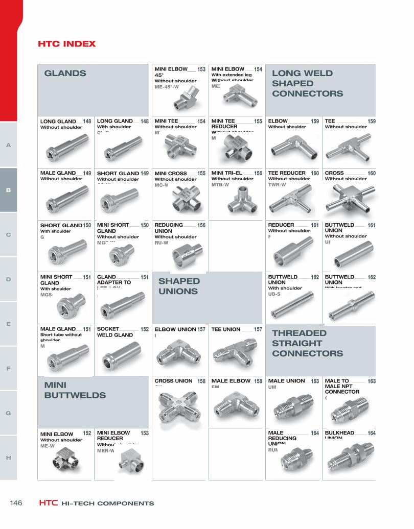
LONG GLAND___ Without shoulder
GL-W
148 LONG GLAND___ With shoulder
GL-S
148 MINI TEE________Without shoulder
MT-W
154 MINI TEE ________REDUCERWithout shoulder
MTR-W
155 ELBOW__________ Without shoulder
EW-W
159 TEE __________ Without shoulder
TW-W
159
MALE GLAND___ Without shoulder
GM-W
149 SHORT GLAND Without shoulder
GS-W
149 MINI CROSS____ Without shoulder
MC-W
155 MINI TRI-EL ____ Without shoulder
MTB-W
156 TEE REDUCER Without shoulder
TWR-W
160 CROSS _________ Without shoulder
CW-W
160
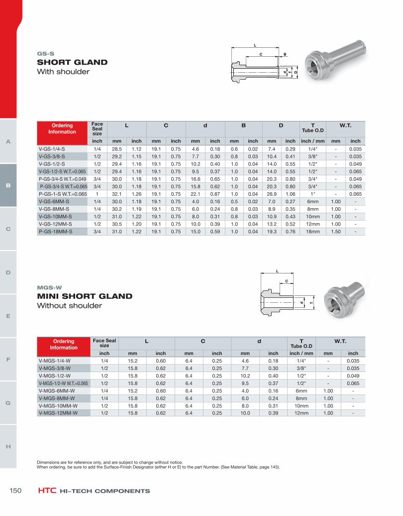
SHORT GLAND With shoulder
GS-S
150 MINI SHORT_____ GLAND Without shoulder
MGS-W
150 REDUCING______ UNIONWithout shoulder
RU-W
156 REDUCER ______ Without shoulder
RW-W
161 BUTTWELD_____UNION Without shoulder
UB-W
161
MINI SHORT ____GLAND With shoulder
MGS-S
151 GLAND___________ADAPTER TOLET-LOK AG
151 SHAPEDUNIONS
BUTTWELD _____UNION With shoulder
UB-S
162 BUTTWELD_____UNION With locator and shoulder
UBL-S
162
MALE GLAND___ Short tube without shoulder
MG-W
151 SOCKET_________WELD GLAND GSW
152 ELBOW UNION EU
157 TEE UNION _____TU
157 THREADED STRAIGHTCONNECTORS
MINIBUTTWELDS
CROSS UNION CU
158 MALE ELBOW_ EM
158 MALE UNION__ UM
163 MALE TO________ MALE NPTCONNECTOR CM
163
MINI ELBOWWithout shoulder
ME-W
152 MINI ELBOW REDUCERWithout shoulder
MER-W
153 MALE ___________REDUCING UNION RUM
164 BULKHEAD______UNION BU
164
HTC INDEX
146
H
G
F
E
D
C
B
A
SHORT__________BULKHEAD UNION SBU
164 MALE TO NPT__BULKHEADCONNECTORBCM
165 MALE PLUG ____MP
169 MALE NUT______NM
169 HIGH FLOWCONNECTORS
MALE TO________ SEAL O-RINGCONNECTORCMOB
165 MALE TO _______FEMALE NPTCONNECTORFC
165 TAPERED________MALE NUT TNM
169 SHORT MALE __NUT SNM
170 LONG HIGH ____ FLOW GLANDHGL
173 HIGH FLOW___MALE TO TUBEHMT
173
MALE TO________LET-LOK UNION UGL
166 MALE TO________ BULKHEAD LET-LOK UNION BUL
166 SWIVELCONNECTORS
HIGH FLOW ____FEMALE NUTHNF
173 HIGH FLOW___MALE NUTHNM
173
MALE TO SHORT BULKHEAD LET-LOK UNION SBUL
166 BULKHEAD TO TUBE UNION Without shoulder
BHUT-W
167 FEMALE TO______MALE UNIONUMF
170 FEMALE TO___MALE NPTCONNECTORMCF
170 ORDERING INFORMATION
SHORT _________BULKHEAD TO TUBE UNION Without shoulder
SBHUT-W
167 FEMALE TO_____FEMALE UNION UFF
171 FEMALE TO____FEMALE NPTCONNECTORFCF
171
CAPS, NUTS & PLUGS
FEMALE TO ____ LET-LOK CONNECTOR FHTL
171
COUPLING _____ CP
167 DOUBLE ________FEMALE UNIONDFU
168 GASKETS
FEMALE NUT___ NF
168 FEMALE CAP___CF
168 GASKET_________ GA
172 RETAINED_______ GASKETGA-RT
172
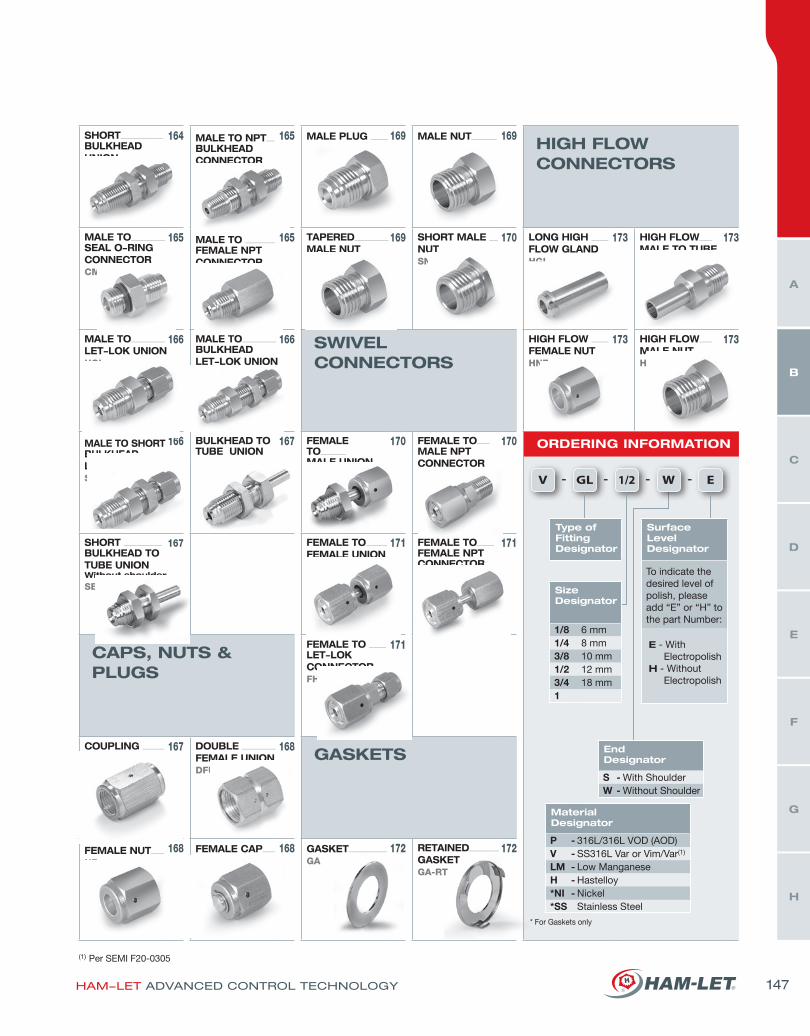
V - - - -GL 1/2 E
* For Gaskets only
MaterialDesignator
P - 316L/316L VOD (AOD)V - SS316L Var or Vim/Var(1)
LM - Low ManganeseH - Hastelloy*NI - Nickel*SS Stainless Steel
Type of FittingDesignator
SizeDesignator
1/8 6 mm1/4 8 mm3/8 10 mm1/2 12 mm3/4 18 mm1
EndDesignator
S - With ShoulderW - Without Shoulder
W
SurfaceLevelDesignator
To indicate the desired level of polish, please add “E” or “H” to the part Number:
E - With ElectropolishH - Without Electropolish
(1) Per SEMI F20-0305
HAM-LET ADVANCED CONTROL TECHNOLOGY 147
H
G
F
E
D
C
B
A
HI-TECH COMPONENTS
OrderingInformation
Face Sealsize
L C d TTube O.D
W.T.
inch mm inch mm inch mm inch inch / mm mm inch
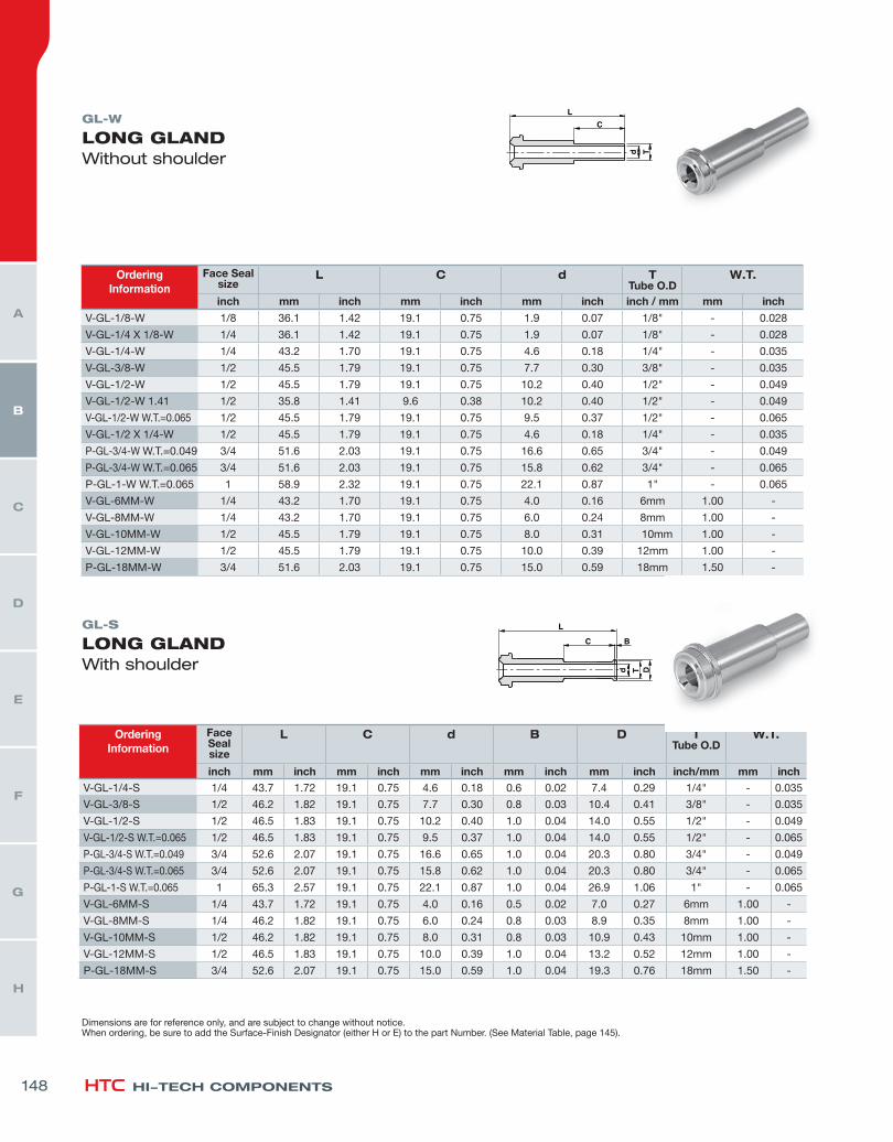
V-GL-1/8-W 1/8 36.1 1.42 19.1 0.75 1.9 0.07 1/8" - 0.028
V-GL-1/4 X 1/8-W 1/4 36.1 1.42 19.1 0.75 1.9 0.07 1/8" - 0.028
V-GL-1/4-W 1/4 43.2 1.70 19.1 0.75 4.6 0.18 1/4" - 0.035
V-GL-3/8-W 1/2 45.5 1.79 19.1 0.75 7.7 0.30 3/8" - 0.035
V-GL-1/2-W 1/2 45.5 1.79 19.1 0.75 10.2 0.40 1/2" - 0.049
V-GL-1/2-W 1.41 1/2 35.8 1.41 9.6 0.38 10.2 0.40 1/2" - 0.049
V-GL-1/2-W W.T.=0.065 1/2 45.5 1.79 19.1 0.75 9.5 0.37 1/2" - 0.065
V-GL-1/2 X 1/4-W 1/2 45.5 1.79 19.1 0.75 4.6 0.18 1/4" - 0.035
P-GL-3/4-W W.T.=0.049 3/4 51.6 2.03 19.1 0.75 16.6 0.65 3/4" - 0.049
P-GL-3/4-W W.T.=0.065 3/4 51.6 2.03 19.1 0.75 15.8 0.62 3/4" - 0.065
P-GL-1-W W.T.=0.065 1 58.9 2.32 19.1 0.75 22.1 0.87 1" - 0.065
V-GL-6MM-W 1/4 43.2 1.70 19.1 0.75 4.0 0.16 6mm 1.00 -
V-GL-8MM-W 1/4 43.2 1.70 19.1 0.75 6.0 0.24 8mm 1.00 -
V-GL-10MM-W 1/2 45.5 1.79 19.1 0.75 8.0 0.31 10mm 1.00 -
V-GL-12MM-W 1/2 45.5 1.79 19.1 0.75 10.0 0.39 12mm 1.00 -
P-GL-18MM-W 3/4 51.6 2.03 19.1 0.75 15.0 0.59 18mm 1.50 -
OrderingInformation
Face Sealsize
L C d B D TTube O.D
W.T.
inch mm inch mm inch mm inch mm inch mm inch inch/mm mm inchV-GL-1/4-S 1/4 43.7 1.72 19.1 0.75 4.6 0.18 0.6 0.02 7.4 0.29 1/4" - 0.035
V-GL-3/8-S 1/2 46.2 1.82 19.1 0.75 7.7 0.30 0.8 0.03 10.4 0.41 3/8" - 0.035
V-GL-1/2-S 1/2 46.5 1.83 19.1 0.75 10.2 0.40 1.0 0.04 14.0 0.55 1/2" - 0.049
V-GL-1/2-S W.T.=0.065 1/2 46.5 1.83 19.1 0.75 9.5 0.37 1.0 0.04 14.0 0.55 1/2" - 0.065
P-GL-3/4-S W.T.=0.049 3/4 52.6 2.07 19.1 0.75 16.6 0.65 1.0 0.04 20.3 0.80 3/4" - 0.049
P-GL-3/4-S W.T.=0.065 3/4 52.6 2.07 19.1 0.75 15.8 0.62 1.0 0.04 20.3 0.80 3/4" - 0.065
P-GL-1-S W.T.=0.065 1 65.3 2.57 19.1 0.75 22.1 0.87 1.0 0.04 26.9 1.06 1" - 0.065
V-GL-6MM-S 1/4 43.7 1.72 19.1 0.75 4.0 0.16 0.5 0.02 7.0 0.27 6mm 1.00 -
V-GL-8MM-S 1/4 46.2 1.82 19.1 0.75 6.0 0.24 0.8 0.03 8.9 0.35 8mm 1.00 -
V-GL-10MM-S 1/2 46.2 1.82 19.1 0.75 8.0 0.31 0.8 0.03 10.9 0.43 10mm 1.00 -
V-GL-12MM-S 1/2 46.5 1.83 19.1 0.75 10.0 0.39 1.0 0.04 13.2 0.52 12mm 1.00 -
P-GL-18MM-S 3/4 52.6 2.07 19.1 0.75 15.0 0.59 1.0 0.04 19.3 0.76 18mm 1.50 -
GL-W
LONG GLAND Without shoulder
GL-S
LONG GLAND With shoulder
Dimensions are for reference only, and are subject to change without notice.When ordering, be sure to add the Surface-Finish Designator (either H or E) to the part Number. (See Material Table, page 145).
148
H
G
F
E
D
C
B
A
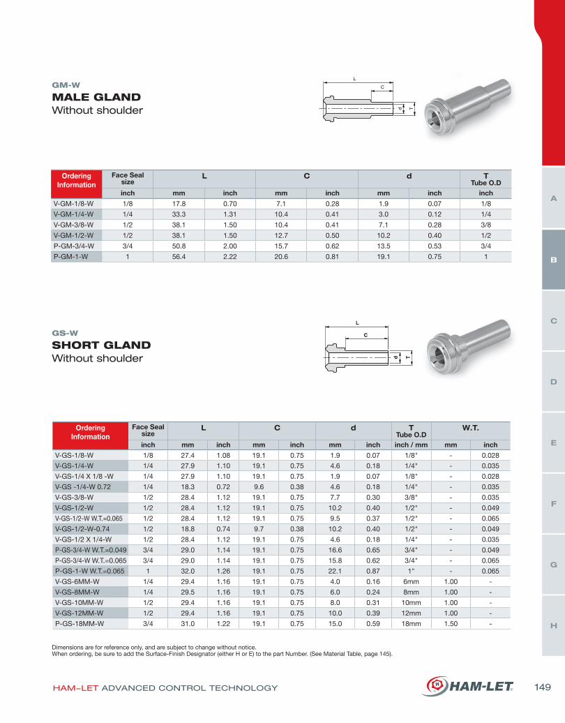
OrderingInformation
Face Sealsize
L C d TTube O.D
inch mm inch mm inch mm inch inch
V-GM-1/8-W 1/8 17.8 0.70 7.1 0.28 1.9 0.07 1/8
V-GM-1/4-W 1/4 33.3 1.31 10.4 0.41 3.0 0.12 1/4
V-GM-3/8-W 1/2 38.1 1.50 10.4 0.41 7.1 0.28 3/8
V-GM-1/2-W 1/2 38.1 1.50 12.7 0.50 10.2 0.40 1/2
P-GM-3/4-W 3/4 50.8 2.00 15.7 0.62 13.5 0.53 3/4
P-GM-1-W 1 56.4 2.22 20.6 0.81 19.1 0.75 1
OrderingInformation
Face Sealsize
L C d TTube O.D
W.T.
inch mm inch mm inch mm inch inch / mm mm inch
V-GS-1/8-W 1/8 27.4 1.08 19.1 0.75 1.9 0.07 1/8" - 0.028
V-GS-1/4-W 1/4 27.9 1.10 19.1 0.75 4.6 0.18 1/4" - 0.035
V-GS-1/4 X 1/8 -W 1/4 27.9 1.10 19.1 0.75 1.9 0.07 1/8" - 0.028
V-GS -1/4-W 0.72 1/4 18.3 0.72 9.6 0.38 4.6 0.18 1/4" - 0.035
V-GS-3/8-W 1/2 28.4 1.12 19.1 0.75 7.7 0.30 3/8" - 0.035
V-GS-1/2-W 1/2 28.4 1.12 19.1 0.75 10.2 0.40 1/2" - 0.049
V-GS-1/2-W W.T.=0.065 1/2 28.4 1.12 19.1 0.75 9.5 0.37 1/2" - 0.065
V-GS-1/2-W-0.74 1/2 18.8 0.74 9.7 0.38 10.2 0.40 1/2" - 0.049
V-GS-1/2 X 1/4-W 1/2 28.4 1.12 19.1 0.75 4.6 0.18 1/4" - 0.035
P-GS-3/4-W W.T.=0.049 3/4 29.0 1.14 19.1 0.75 16.6 0.65 3/4" - 0.049
P-GS-3/4-W W.T.=0.065 3/4 29.0 1.14 19.1 0.75 15.8 0.62 3/4" - 0.065
P-GS-1-W W.T.=0.065 1 32.0 1.26 19.1 0.75 22.1 0.87 1" - 0.065
V-GS-6MM-W 1/4 29.4 1.16 19.1 0.75 4.0 0.16 6mm 1.00 -
V-GS-8MM-W 1/4 29.5 1.16 19.1 0.75 6.0 0.24 8mm 1.00 -
V-GS-10MM-W 1/2 29.4 1.16 19.1 0.75 8.0 0.31 10mm 1.00 -
V-GS-12MM-W 1/2 29.4 1.16 19.1 0.75 10.0 0.39 12mm 1.00 -
P-GS-18MM-W 3/4 31.0 1.22 19.1 0.75 15.0 0.59 18mm 1.50 -
GM-W
MALE GLAND Without shoulder
GS-W
SHORT GLAND Without shoulder
Dimensions are for reference only, and are subject to change without notice.When ordering, be sure to add the Surface-Finish Designator (either H or E) to the part Number. (See Material Table, page 145).
L
HAM-LET ADVANCED CONTROL TECHNOLOGY 149
H
G
F
E
D
C
B
A
HI-TECH COMPONENTS
OrderingInformation
Face Sealsize
L C d TTube O.D
W.T.
inch mm inch mm inch mm inch inch / mm mm inch
V-MGS-1/4-W 1/4 15.2 0.60 6.4 0.25 4.6 0.18 1/4" - 0.035
V-MGS-3/8-W 1/2 15.8 0.62 6.4 0.25 7.7 0.30 3/8" - 0.035
V-MGS-1/2-W 1/2 15.8 0.62 6.4 0.25 10.2 0.40 1/2" - 0.049
V-MGS-1/2-W W.T.=0.065 1/2 15.8 0.62 6.4 0.25 9.5 0.37 1/2" - 0.065
V-MGS-6MM-W 1/4 15.2 0.60 6.4 0.25 4.0 0.16 6mm 1.00 -
V-MGS-8MM-W 1/4 15.8 0.62 6.4 0.25 6.0 0.24 8mm 1.00 -
V-MGS-10MM-W 1/2 15.8 0.62 6.4 0.25 8.0 0.31 10mm 1.00 -V-MGS-12MM-W 1/2 15.8 0.62 6.4 0.25 10.0 0.39 12mm 1.00 -
GS-S
SHORT GLAND With shoulder
MGS-W
MINI SHORT GLAND Without shoulder
OrderingInformation
Face Sealsize
L C d B D TTube O.D
W.T.
inch mm inch mm inch mm inch mm inch mm inch inch / mm mm inch
V-GS-1/4-S 1/4 28.5 1.12 19.1 0.75 4.6 0.18 0.6 0.02 7.4 0.29 1/4" - 0.035
V-GS-3/8-S 1/2 29.2 1.15 19.1 0.75 7.7 0.30 0.8 0.03 10.4 0.41 3/8" - 0.035
V-GS-1/2-S 1/2 29.4 1.16 19.1 0.75 10.2 0.40 1.0 0.04 14.0 0.55 1/2" - 0.049
V-GS-1/2-S W.T.=0.065 1/2 29.4 1.16 19.1 0.75 9.5 0.37 1.0 0.04 14.0 0.55 1/2" - 0.065
P-GS-3/4-S W.T.=0.049 3/4 30.0 1.18 19.1 0.75 16.6 0.65 1.0 0.04 20.3 0.80 3/4" - 0.049
P-GS-3/4-S W.T.=0.065 3/4 30.0 1.18 19.1 0.75 15.8 0.62 1.0 0.04 20.3 0.80 3/4" - 0.065
P-GS-1-S W.T.=0.065 1 32.1 1.26 19.1 0.75 22.1 0.87 1.0 0.04 26.9 1.06 1" - 0.065
V-GS-6MM-S 1/4 30.0 1.18 19.1 0.75 4.0 0.16 0.5 0.02 7.0 0.27 6mm 1.00 -
V-GS-8MM-S 1/4 30.2 1.19 19.1 0.75 6.0 0.24 0.8 0.03 8.9 0.35 8mm 1.00 -
V-GS-10MM-S 1/2 31.0 1.22 19.1 0.75 8.0 0.31 0.8 0.03 10.9 0.43 10mm 1.00 -
V-GS-12MM-S 1/2 30.5 1.20 19.1 0.75 10.0 0.39 1.0 0.04 13.2 0.52 12mm 1.00 -
P-GS-18MM-S 3/4 31.0 1.22 19.1 0.75 15.0 0.59 1.0 0.04 19.3 0.76 18mm 1.50 -
Dimensions are for reference only, and are subject to change without notice.When ordering, be sure to add the Surface-Finish Designator (either H or E) to the part Number. (See Material Table, page 145).
150
H
G
F
E
D
C
B
A

AG
GLAND ADAPTER TO LET-LOK
OrderingInformation
Face Sealsize
L C d TTube O.D
inch mm inch mm inch mm inch inch/mm
V-AG-1/4 1/4 41.2 1.62 15.9 0.62 4.3 0.17 1/4"
P-AG-3/8 1/2 46.0 1.81 17.5 0.69 6.8 0.27 3/8"
V-AG-1/2 1/2 49.3 1.94 24.4 0.96 9.4 0.37 1/2"
V-AG-6M 1/4 41.2 1.62 15.7 0.62 4.0 0.16 6mm
MGS-S
MINI SHORT GLAND With shoulder
MG-W
MALE GLANDShort tube without shoulder
OrderingInformation
Face Sealsize
L C d B D TTube O.D
W.T.
inch mm inch mm inch mm inch mm inch mm inch inch / mm mm inch
V-MGS-1/4-S 1/4 15.8 0.62 6.4 0.25 4.6 0.18 0.6 0.02 7.4 0.29 1/4" - 0.035
V-MGS-3/8-S 1/2 16.5 0.65 6.4 0.25 7.7 0.30 0.8 0.03 10.4 0.41 3/8" - 0.035
V-MGS-1/2-S 1/2 16.8 0.66 6.4 0.25 10.2 0.40 1.0 0.04 14.0 0.55 1/2" - 0.049
V-MGS-1/2-S W.T.=0.065 1/2 16.8 0.66 6.4 0.25 9.5 0.37 1.0 0.04 14.0 0.55 1/2" - 0.065
V-MGS-6MM-S 1/4 15.8 0.62 6.4 0.25 4.0 0.16 0.5 0.02 7.0 0.27 6mm 1.00 -
V-MGS-8MM-S 1/4 16.5 0.65 6.4 0.25 6.0 0.24 0.8 0.03 8.9 0.35 8mm 1.00 -V-MGS-10MM-S 1/2 16.5 0.65 6.4 0.25 8.0 0.31 0.8 0.03 10.9 0.43 10mm 1.00 -V-MGS-12MM-S 1/2 16.8 0.66 6.4 0.25 10.0 0.39 1.0 0.04 13.2 0.52 12mm 1.00 -
OrderingInformation
Face Sealsize
L C d TTube O.D
W.T.
inch mm inch mm inch mm inch inch / mm mm inch
V-MG-1/4-W 1/4 30.5 1.20 6.4 0.25 4.6 0.18 1/4" - 0.035
V-MG-1/4-W 1.32 1/4 33.5 1.32 9.6 0.38 4.6 0.18 1/4" - 0.035
V-MG-3/8-W 1/2 32.8 1.29 6.4 0.25 7.7 0.30 3/8" - 0.035
V-MG-1/2-W 1/2 32.8 1.29 6.4 0.25 10.2 0.40 1/2" - 0.049
V-MG-6MM-W 1/4 30.5 1.20 6.4 0.25 4.0 0.16 6mm 1.00 -
V-MG-8MM-W 1/4 30.5 1.20 6.4 0.25 6.0 0.24 8mm 1.00 -V-MG-10MM-W 1/2 32.8 1.29 6.4 0.25 8.0 0.31 10mm 1.00 -V-MG-12MM-W 1/2 32.8 1.29 6.4 0.25 10.0 0.39 12mm 1.00 -
Dimensions are for reference only, and are subject to change without notice.When ordering, be sure to add the Surface-Finish Designator (either H or E) to the part Number. (See Material Table, page 145).
HAM-LET ADVANCED CONTROL TECHNOLOGY 151
H
G
F
E
D
C
B
A
HI-TECH COMPONENTS
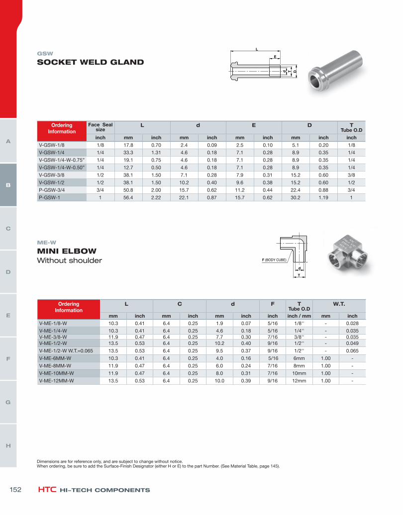
OrderingInformation
L C d F TTube O.D
W.T.
mm inch mm inch mm inch inch inch / mm mm inch
V-ME-1/8-W 10.3 0.41 6.4 0.25 1.9 0.07 5/16 1/8'' - 0.028
V-ME-1/4-W 10.3 0.41 6.4 0.25 4.6 0.18 5/16 1/4'' - 0.035V-ME-3/8-W 11.9 0.47 6.4 0.25 7.7 0.30 7/16 3/8'' - 0.035V-ME-1/2-W 13.5 0.53 6.4 0.25 10.2 0.40 9/16 1/2'' - 0.049
V-ME-1/2-W W.T.=0.065 13.5 0.53 6.4 0.25 9.5 0.37 9/16 1/2'' - 0.065
V-ME-6MM-W 10.3 0.41 6.4 0.25 4.0 0.16 5/16 6mm 1.00 -
V-ME-8MM-W 11.9 0.47 6.4 0.25 6.0 0.24 7/16 8mm 1.00 -
V-ME-10MM-W 11.9 0.47 6.4 0.25 8.0 0.31 7/16 10mm 1.00 -
V-ME-12MM-W 13.5 0.53 6.4 0.25 10.0 0.39 9/16 12mm 1.00 -
OrderingInformation
Face Sealsize
L d E D TTube O.D
inch mm inch mm inch mm inch mm inch inch
V-GSW-1/8 1/8 17.8 0.70 2.4 0.09 2.5 0.10 5.1 0.20 1/8
V-GSW-1/4 1/4 33.3 1.31 4.6 0.18 7.1 0.28 8.9 0.35 1/4
V-GSW-1/4-W-0.75” 1/4 19.1 0.75 4.6 0.18 7.1 0.28 8.9 0.35 1/4
V-GSW-1/4-W-0.50” 1/4 12.7 0.50 4.6 0.18 7.1 0.28 8.9 0.35 1/4
V-GSW-3/8 1/2 38.1 1.50 7.1 0.28 7.9 0.31 15.2 0.60 3/8
V-GSW-1/2 1/2 38.1 1.50 10.2 0.40 9.6 0.38 15.2 0.60 1/2
P-GSW-3/4 3/4 50.8 2.00 15.7 0.62 11.2 0.44 22.4 0.88 3/4
P-GSW-1 1 56.4 2.22 22.1 0.87 15.7 0.62 30.2 1.19 1
GSW
SOCKET WELD GLAND
ME-W
MINI ELBOWWithout shoulder
Dimensions are for reference only, and are subject to change without notice.When ordering, be sure to add the Surface-Finish Designator (either H or E) to the part Number. (See Material Table, page 145).
152
H
G
F
E
D
C
B
A
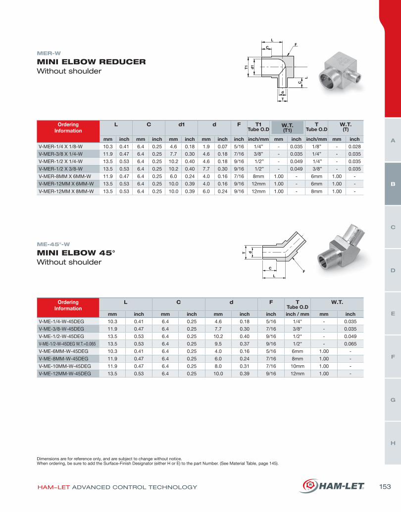
OrderingInformation
L C d F TTube O.D
W.T.
mm inch mm inch mm inch inch inch / mm mm inch
V-ME-1/4-W-45DEG 10.3 0.41 6.4 0.25 4.6 0.18 5/16 1/4" - 0.035
V-ME-3/8-W-45DEG 11.9 0.47 6.4 0.25 7.7 0.30 7/16 3/8" - 0.035
V-ME-1/2-W-45DEG 13.5 0.53 6.4 0.25 10.2 0.40 9/16 1/2" - 0.049
V-ME-1/2-W-45DEG W.T.=0.065 13.5 0.53 6.4 0.25 9.5 0.37 9/16 1/2" - 0.065
V-ME-6MM-W-45DEG 10.3 0.41 6.4 0.25 4.0 0.16 5/16 6mm 1.00 -
V-ME-8MM-W-45DEG 11.9 0.47 6.4 0.25 6.0 0.24 7/16 8mm 1.00 -
V-ME-10MM-W-45DEG 11.9 0.47 6.4 0.25 8.0 0.31 7/16 10mm 1.00 -
V-ME-12MM-W-45DEG 13.5 0.53 6.4 0.25 10.0 0.39 9/16 12mm 1.00 -
OrderingInformation
L C d1 d F T1Tube O.D
W.T.(T1)
TTube O.D
W.T.(T)
mm inch mm inch mm inch mm inch inch inch/mm mm inch inch/mm mm inch
V-MER-1/4 X 1/8-W 10.3 0.41 6.4 0.25 4.6 0.18 1.9 0.07 5/16 1/4” - 0.035 1/8” - 0.028
V-MER-3/8 X 1/4-W 11.9 0.47 6.4 0.25 7.7 0.30 4.6 0.18 7/16 3/8” - 0.035 1/4” - 0.035
V-MER-1/2 X 1/4-W 13.5 0.53 6.4 0.25 10.2 0.40 4.6 0.18 9/16 1/2” - 0.049 1/4” - 0.035
V-MER-1/2 X 3/8-W 13.5 0.53 6.4 0.25 10.2 0.40 7.7 0.30 9/16 1/2” - 0.049 3/8” - 0.035
V-MER-8MM X 6MM-W 11.9 0.47 6.4 0.25 6.0 0.24 4.0 0.16 7/16 8mm 1.00 - 6mm 1.00 -
V-MER-12MM X 6MM-W 13.5 0.53 6.4 0.25 10.0 0.39 4.0 0.16 9/16 12mm 1.00 - 6mm 1.00 -
V-MER-12MM X 8MM-W 13.5 0.53 6.4 0.25 10.0 0.39 6.0 0.24 9/16 12mm 1.00 - 8mm 1.00 -
MER-W
MINI ELBOW REDUCER Without shoulder
ME-45°-W
MINI ELBOW 45°Without shoulder
Dimensions are for reference only, and are subject to change without notice.When ordering, be sure to add the Surface-Finish Designator (either H or E) to the part Number. (See Material Table, page 145).
HAM-LET ADVANCED CONTROL TECHNOLOGY 153
H
G
F
E
D
C
B
A
HI-TECH COMPONENTS
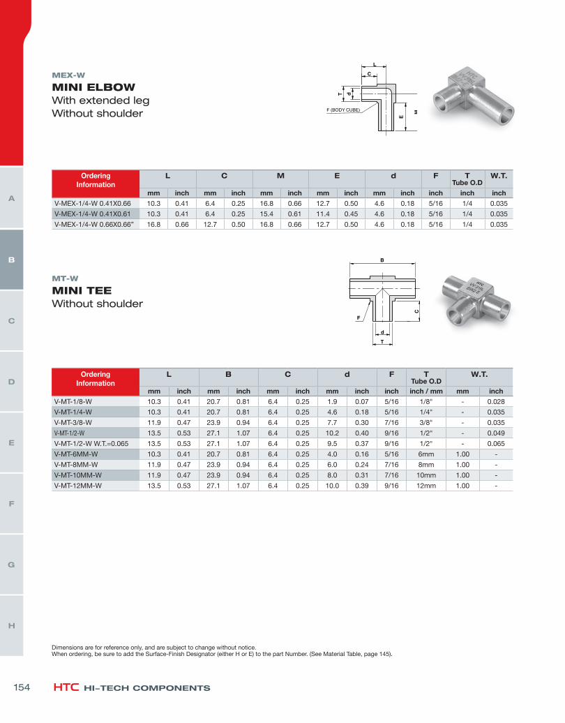
OrderingInformation
L C M E d F TTube O.D
W.T.
mm inch mm inch mm inch mm inch mm inch inch inch inch
V-MEX-1/4-W 0.41X0.66 10.3 0.41 6.4 0.25 16.8 0.66 12.7 0.50 4.6 0.18 5/16 1/4 0.035
V-MEX-1/4-W 0.41X0.61 10.3 0.41 6.4 0.25 15.4 0.61 11.4 0.45 4.6 0.18 5/16 1/4 0.035
V-MEX-1/4-W 0.66X0.66” 16.8 0.66 12.7 0.50 16.8 0.66 12.7 0.50 4.6 0.18 5/16 1/4 0.035
MEX-W
MINI ELBOW With extended legWithout shoulder
MT-W
MINI TEEWithout shoulder
OrderingInformation
L B C d F TTube O.D
W.T.
mm inch mm inch mm inch mm inch inch inch / mm mm inch
V-MT-1/8-W 10.3 0.41 20.7 0.81 6.4 0.25 1.9 0.07 5/16 1/8" - 0.028
V-MT-1/4-W 10.3 0.41 20.7 0.81 6.4 0.25 4.6 0.18 5/16 1/4" - 0.035
V-MT-3/8-W 11.9 0.47 23.9 0.94 6.4 0.25 7.7 0.30 7/16 3/8" - 0.035
V-MT-1/2-W 13.5 0.53 27.1 1.07 6.4 0.25 10.2 0.40 9/16 1/2" - 0.049
V-MT-1/2-W W.T.=0.065 13.5 0.53 27.1 1.07 6.4 0.25 9.5 0.37 9/16 1/2" - 0.065
V-MT-6MM-W 10.3 0.41 20.7 0.81 6.4 0.25 4.0 0.16 5/16 6mm 1.00 -
V-MT-8MM-W 11.9 0.47 23.9 0.94 6.4 0.25 6.0 0.24 7/16 8mm 1.00 -
V-MT-10MM-W 11.9 0.47 23.9 0.94 6.4 0.25 8.0 0.31 7/16 10mm 1.00 -
V-MT-12MM-W 13.5 0.53 27.1 1.07 6.4 0.25 10.0 0.39 9/16 12mm 1.00 -
Dimensions are for reference only, and are subject to change without notice.When ordering, be sure to add the Surface-Finish Designator (either H or E) to the part Number. (See Material Table, page 145).
154
H
G
F
E
D
C
B
A
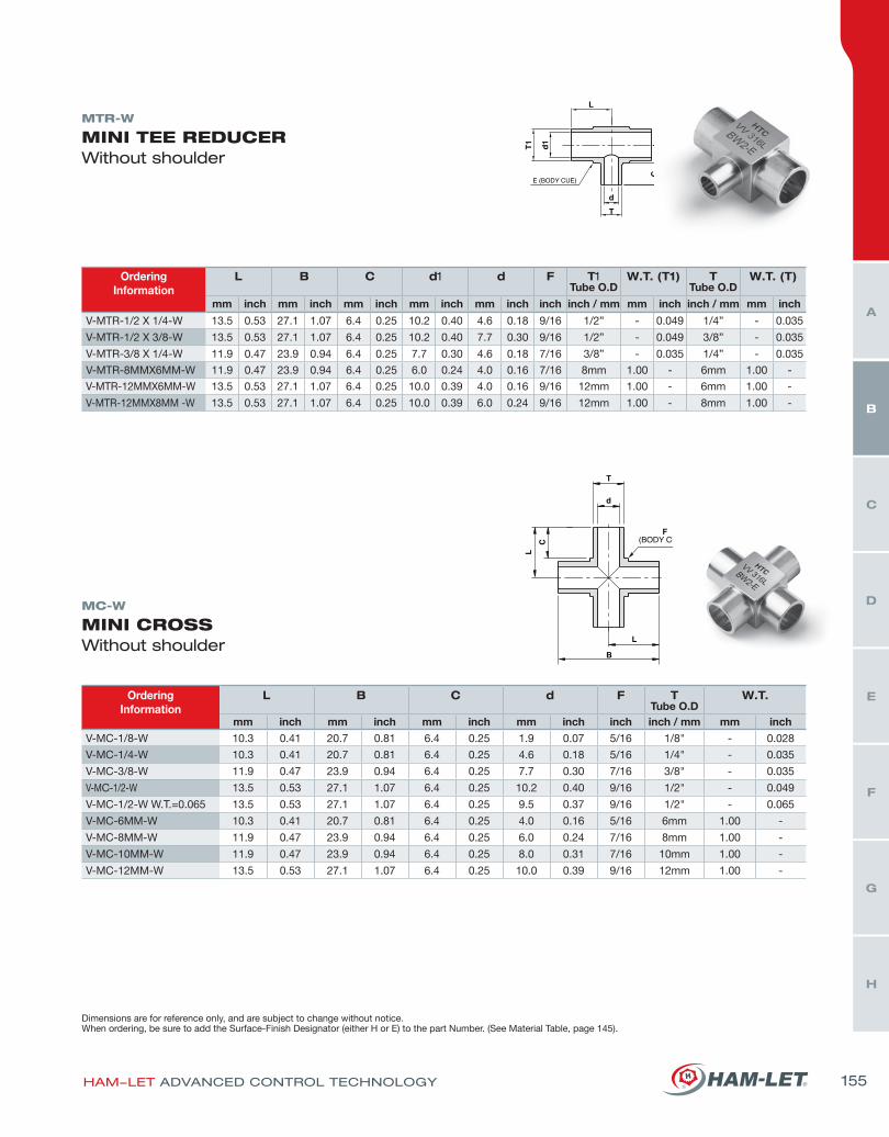
OrderingInformation
L B C d1 d F T1Tube O.D
W.T. (T1) TTube O.D
W.T. (T)
mm inch mm inch mm inch mm inch mm inch inch inch / mm mm inch inch / mm mm inch
V-MTR-1/2 X 1/4-W 13.5 0.53 27.1 1.07 6.4 0.25 10.2 0.40 4.6 0.18 9/16 1/2” - 0.049 1/4” - 0.035
V-MTR-1/2 X 3/8-W 13.5 0.53 27.1 1.07 6.4 0.25 10.2 0.40 7.7 0.30 9/16 1/2” - 0.049 3/8” - 0.035
V-MTR-3/8 X 1/4-W 11.9 0.47 23.9 0.94 6.4 0.25 7.7 0.30 4.6 0.18 7/16 3/8” - 0.035 1/4” - 0.035
V-MTR-8MMX6MM-W 11.9 0.47 23.9 0.94 6.4 0.25 6.0 0.24 4.0 0.16 7/16 8mm 1.00 - 6mm 1.00 -
V-MTR-12MMX6MM-W 13.5 0.53 27.1 1.07 6.4 0.25 10.0 0.39 4.0 0.16 9/16 12mm 1.00 - 6mm 1.00 -
V-MTR-12MMX8MM -W 13.5 0.53 27.1 1.07 6.4 0.25 10.0 0.39 6.0 0.24 9/16 12mm 1.00 - 8mm 1.00 -
MTR-W
MINI TEE REDUCER Without shoulder
MC-W
MINI CROSSWithout shoulder
OrderingInformation
L B C d F TTube O.D
W.T.
mm inch mm inch mm inch mm inch inch inch / mm mm inch
V-MC-1/8-W 10.3 0.41 20.7 0.81 6.4 0.25 1.9 0.07 5/16 1/8" - 0.028
V-MC-1/4-W 10.3 0.41 20.7 0.81 6.4 0.25 4.6 0.18 5/16 1/4" - 0.035
V-MC-3/8-W 11.9 0.47 23.9 0.94 6.4 0.25 7.7 0.30 7/16 3/8" - 0.035
V-MC-1/2-W 13.5 0.53 27.1 1.07 6.4 0.25 10.2 0.40 9/16 1/2" - 0.049
V-MC-1/2-W W.T.=0.065 13.5 0.53 27.1 1.07 6.4 0.25 9.5 0.37 9/16 1/2" - 0.065
V-MC-6MM-W 10.3 0.41 20.7 0.81 6.4 0.25 4.0 0.16 5/16 6mm 1.00 -
V-MC-8MM-W 11.9 0.47 23.9 0.94 6.4 0.25 6.0 0.24 7/16 8mm 1.00 -
V-MC-10MM-W 11.9 0.47 23.9 0.94 6.4 0.25 8.0 0.31 7/16 10mm 1.00 -
V-MC-12MM-W 13.5 0.53 27.1 1.07 6.4 0.25 10.0 0.39 9/16 12mm 1.00 -
Dimensions are for reference only, and are subject to change without notice.When ordering, be sure to add the Surface-Finish Designator (either H or E) to the part Number. (See Material Table, page 145).
HAM-LET ADVANCED CONTROL TECHNOLOGY 155
H
G
F
E
D
C
B
A
HI-TECH COMPONENTS
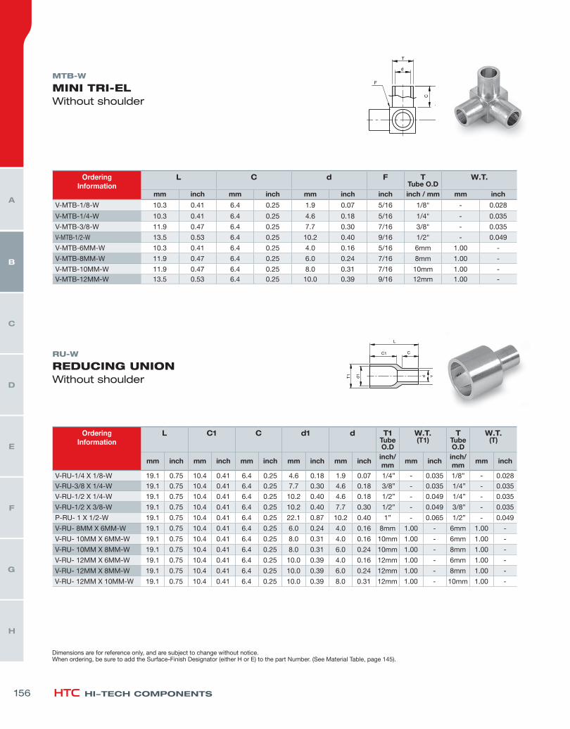
MTB-W
MINI TRI-ELWithout shoulder
RU-W
REDUCING UNIONWithout shoulder
OrderingInformation
L C d F TTube O.D
W.T.
mm inch mm inch mm inch inch inch / mm mm inch
V-MTB-1/8-W 10.3 0.41 6.4 0.25 1.9 0.07 5/16 1/8" - 0.028
V-MTB-1/4-W 10.3 0.41 6.4 0.25 4.6 0.18 5/16 1/4" - 0.035
V-MTB-3/8-W 11.9 0.47 6.4 0.25 7.7 0.30 7/16 3/8" - 0.035
V-MTB-1/2-W 13.5 0.53 6.4 0.25 10.2 0.40 9/16 1/2" - 0.049
V-MTB-6MM-W 10.3 0.41 6.4 0.25 4.0 0.16 5/16 6mm 1.00 -
V-MTB-8MM-W 11.9 0.47 6.4 0.25 6.0 0.24 7/16 8mm 1.00 -
V-MTB-10MM-W 11.9 0.47 6.4 0.25 8.0 0.31 7/16 10mm 1.00 -V-MTB-12MM-W 13.5 0.53 6.4 0.25 10.0 0.39 9/16 12mm 1.00 -
OrderingInformation
L C1 C d1 d T1Tube O.D
W.T.(T1)
TTube O.D
W.T.(T)
mm inch mm inch mm inch mm inch mm inchinch/mm
mm inchinch/mm
mm inch
V-RU-1/4 X 1/8-W 19.1 0.75 10.4 0.41 6.4 0.25 4.6 0.18 1.9 0.07 1/4” - 0.035 1/8” - 0.028
V-RU-3/8 X 1/4-W 19.1 0.75 10.4 0.41 6.4 0.25 7.7 0.30 4.6 0.18 3/8” - 0.035 1/4” - 0.035
V-RU-1/2 X 1/4-W 19.1 0.75 10.4 0.41 6.4 0.25 10.2 0.40 4.6 0.18 1/2” - 0.049 1/4” - 0.035
V-RU-1/2 X 3/8-W 19.1 0.75 10.4 0.41 6.4 0.25 10.2 0.40 7.7 0.30 1/2” - 0.049 3/8” - 0.035
P-RU- 1 X 1/2-W 19.1 0.75 10.4 0.41 6.4 0.25 22.1 0.87 10.2 0.40 1” - 0.065 1/2” - 0.049
V-RU- 8MM X 6MM-W 19.1 0.75 10.4 0.41 6.4 0.25 6.0 0.24 4.0 0.16 8mm 1.00 - 6mm 1.00 -
V-RU- 10MM X 6MM-W 19.1 0.75 10.4 0.41 6.4 0.25 8.0 0.31 4.0 0.16 10mm 1.00 - 6mm 1.00 -
V-RU- 10MM X 8MM-W 19.1 0.75 10.4 0.41 6.4 0.25 8.0 0.31 6.0 0.24 10mm 1.00 - 8mm 1.00 -
V-RU- 12MM X 6MM-W 19.1 0.75 10.4 0.41 6.4 0.25 10.0 0.39 4.0 0.16 12mm 1.00 - 6mm 1.00 -
V-RU- 12MM X 8MM-W 19.1 0.75 10.4 0.41 6.4 0.25 10.0 0.39 6.0 0.24 12mm 1.00 - 8mm 1.00 -
V-RU- 12MM X 10MM-W 19.1 0.75 10.4 0.41 6.4 0.25 10.0 0.39 8.0 0.31 12mm 1.00 - 10mm 1.00 -
Dimensions are for reference only, and are subject to change without notice.When ordering, be sure to add the Surface-Finish Designator (either H or E) to the part Number. (See Material Table, page 145).
156
H
G
F
E
D
C
B
A
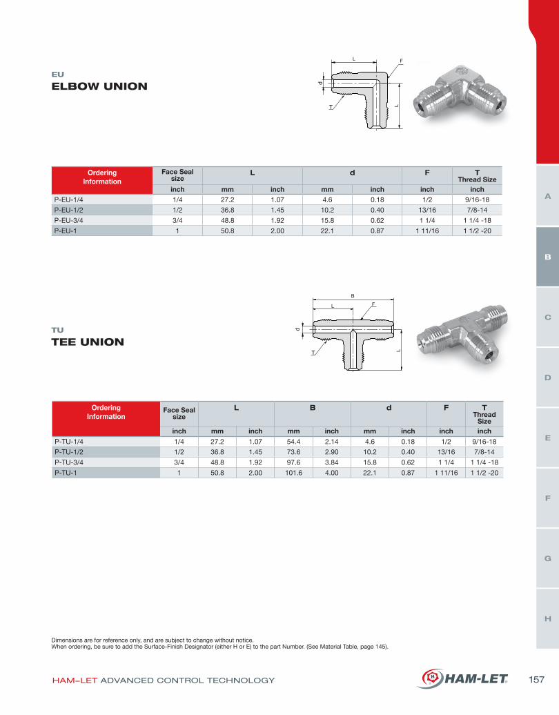
EU
ELBOW UNION
TU
TEE UNION
OrderingInformation
Face Sealsize
L d F TThread Size
inch mm inch mm inch inch inch
P-EU-1/4 1/4 27.2 1.07 4.6 0.18 1/2 9/16-18
P-EU-1/2 1/2 36.8 1.45 10.2 0.40 13/16 7/8-14
P-EU-3/4 3/4 48.8 1.92 15.8 0.62 1 1/4 1 1/4 -18
P-EU-1 1 50.8 2.00 22.1 0.87 1 11/16 1 1/2 -20
OrderingInformation
Face Sealsize
L B d F TThread
Sizeinch mm inch mm inch mm inch inch inch
P-TU-1/4 1/4 27.2 1.07 54.4 2.14 4.6 0.18 1/2 9/16-18
P-TU-1/2 1/2 36.8 1.45 73.6 2.90 10.2 0.40 13/16 7/8-14
P-TU-3/4 3/4 48.8 1.92 97.6 3.84 15.8 0.62 1 1/4 1 1/4 -18
P-TU-1 1 50.8 2.00 101.6 4.00 22.1 0.87 1 11/16 1 1/2 -20
Dimensions are for reference only, and are subject to change without notice.When ordering, be sure to add the Surface-Finish Designator (either H or E) to the part Number. (See Material Table, page 145).
HAM-LET ADVANCED CONTROL TECHNOLOGY 157
H
G
F
E
D
C
B
A
HI-TECH COMPONENTS
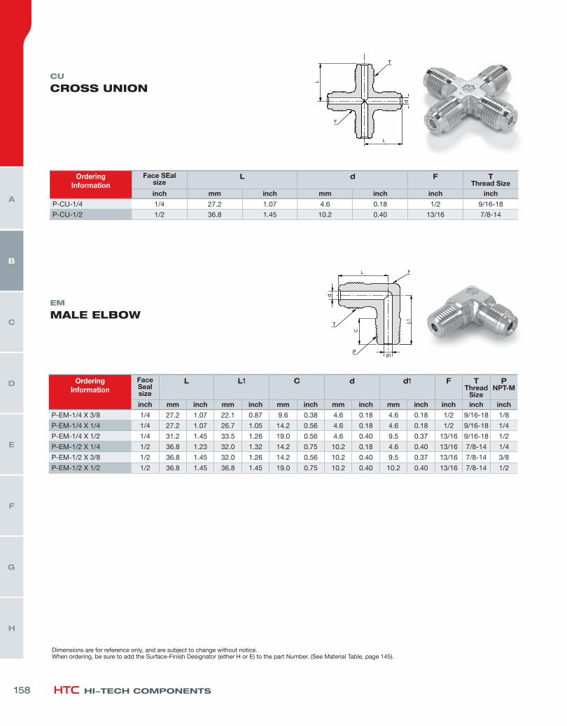
CU
CROSS UNION
EM
MALE ELBOW
OrderingInformation
Face SEalsize
L d F TThread Size
inch mm inch mm inch inch inch
P-CU-1/4 1/4 27.2 1.07 4.6 0.18 1/2 9/16-18
P-CU-1/2 1/2 36.8 1.45 10.2 0.40 13/16 7/8-14
OrderingInformation
Face Sealsize
L L1 C d d1 F TThread
Size
PNPT-M
inch mm inch mm inch mm inch mm inch mm inch inch inch inch
P-EM-1/4 X 3/8 1/4 27.2 1.07 22.1 0.87 9.6 0.38 4.6 0.18 4.6 0.18 1/2 9/16-18 1/8
P-EM-1/4 X 1/4 1/4 27.2 1.07 26.7 1.05 14.2 0.56 4.6 0.18 4.6 0.18 1/2 9/16-18 1/4
P-EM-1/4 X 1/2 1/4 31.2 1.45 33.5 1.26 19.0 0.56 4.6 0.40 9.5 0.37 13/16 9/16-18 1/2
P-EM-1/2 X 1/4 1/2 36.8 1.23 32.0 1.32 14.2 0.75 10.2 0.18 4.6 0.40 13/16 7/8-14 1/4
P-EM-1/2 X 3/8 1/2 36.8 1.45 32.0 1.26 14.2 0.56 10.2 0.40 9.5 0.37 13/16 7/8-14 3/8
P-EM-1/2 X 1/2 1/2 36.8 1.45 36.8 1.45 19.0 0.75 10.2 0.40 10.2 0.40 13/16 7/8-14 1/2
Dimensions are for reference only, and are subject to change without notice.When ordering, be sure to add the Surface-Finish Designator (either H or E) to the part Number. (See Material Table, page 145).
158
H
G
F
E
D
C
B
A
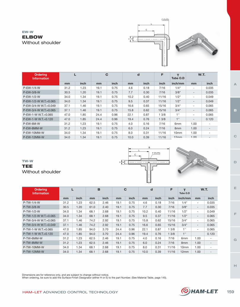
OrderingInformation
L B C d F TTube O.D
W.T.
mm inch mm inch mm inch mm inch inch inch/mm mm inchP-TW-1/4-W 31.2 1.23 62.5 2.46 19.1 0.75 4.6 0.18 7/16 1/4" - 0.035
P-TW-3/8-W 30.5 1.20 61.0 2.40 19.1 0.75 7.7 0.30 7/16 3/8" - 0.035
P-TW-1/2-W 34.0 1.34 68.1 2.68 19.1 0.75 10.2 0.40 11/16 1/2" - 0.049
P-TW-1/2-W W.T.=0.065 34.0 1.34 68.1 2.68 19.1 0.75 9.5 0.37 11/16 1/2" - 0.065
P-TW-3/4-W W.T.=0.065 37.1 1.46 74.2 2.92 19.1 0.75 15.8 0.62 15/16 3/4" - 0.065
P-TW-3/4-W W.T.=0.049 37.1 1.46 74.2 2.92 19.1 0.75 16.6 0.65 15/16 3/4" - 0.065
P-TW-1-W W.T.=0.065 47.0 1.85 94.0 3.70 24.4 0.96 22.1 0.87 1 3/8 1'' - 0.065
P-TW-1-W W.T.=0.120 47.0 1.85 94.0 3.70 24.4 0.96 19.4 0.76 1 3/8 1'' 0.120
P-TW-6MM-W 31.2 1.23 62.5 2.46 19.1 0.75 4.0 0.16 7/16 6mm 1.00 -
P-TW-8MM-W 31.2 1.23 62.5 2.46 19.1 0.75 6.0 0.24 7/16 8mm 1.00 -
P-TW-10MM-W 34.0 1.34 68.1 2.68 19.1 0.75 8.0 0.31 11/16 10mm 1.00 -
P-TW-12MM-W 34.0 1.34 68.1 2.68 19.1 0.75 10.0 0.39 11/16 12mm 1.00 -
EW-W
ELBOW Without shoulder
TW-W
TEEWithout shoulder
OrderingInformation
L C d F TTube O.D
W.T.
mm inch mm inch mm inch inch inch/mm mm inch
P-EW-1/4-W 31.2 1.23 19.1 0.75 4.6 0.18 7/16 1/4" - 0.035
P-EW-3/8-W 30.5 1.20 19.1 0.75 7.7 0.30 7/16 3/8" - 0.035
P-EW-1/2-W 34.0 1.34 19.1 0.75 10.2 0.40 11/16 1/2" - 0.049
P-EW-1/2-W W.T.=0.065 34.0 1.34 19.1 0.75 9.5 0.37 11/16 1/2" - 0.049
P-EW-3/4-W W.T.=0.049 37.1 1.46 19.1 0.75 16.6 0.65 15/16 3/4" - 0.065
P-EW-3/4-W W.T.=0.065 37.1 1.46 19.1 0.75 15.8 0.62 15/16 3/4" - 0.065
P-EW-1-W W.T.=0.065 47.0 1.85 24.4 0.96 22.1 0.87 1 3/8 1'' - 0.065
P-EW-1-W W.T.=0.120 47.0 1.85 24.4 0.96 19.4 0.76 1 3/8 1'' - 0.120
P-EW-6M-W 31.2 1.23 19.1 0.75 4.0 0.16 7/16 6mm 1.00 -
P-EW-8MM-W 31.2 1.23 19.1 0.75 6.0 0.24 7/16 8mm 1.00 -
P-EW-10MM-W 34.0 1.34 19.1 0.75 8.0 0.31 11/16 10mm 1.00 -
P-EW-12MM-W 34.0 1.34 19.1 0.75 10.0 0.39 11/16 12mm 1.00 -
Dimensions are for reference only, and are subject to change without notice.When ordering, be sure to add the Surface-Finish Designator (either H or E) to the part Number. (See Material Table, page 145).
HAM-LET ADVANCED CONTROL TECHNOLOGY 159
H
G
F
E
D
C
B
A
HI-TECH COMPONENTS
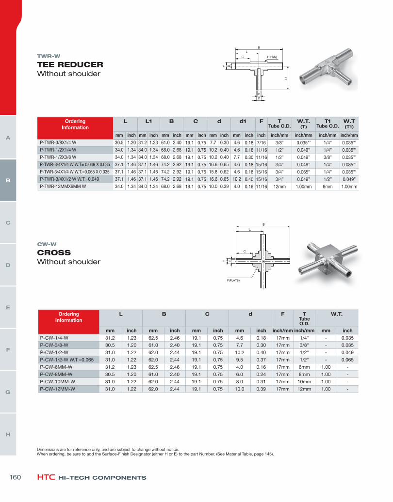
CW-W
CROSSWithout shoulder
OrderingInformation
L B C d F TTube O.D.
W.T.
mm inch mm inch mm inch mm inch inch/mm inch/mm mm inch
P-CW-1/4-W 31.2 1.23 62.5 2.46 19.1 0.75 4.6 0.18 17mm 1/4" - 0.035
P-CW-3/8-W 30.5 1.20 61.0 2.40 19.1 0.75 7.7 0.30 17mm 3/8" - 0.035
P-CW-1/2-W 31.0 1.22 62.0 2.44 19.1 0.75 10.2 0.40 17mm 1/2" - 0.049
P-CW-1/2-W W.T.=0.065 31.0 1.22 62.0 2.44 19.1 0.75 9.5 0.37 17mm 1/2" - 0.065
P-CW-6MM-W 31.2 1.23 62.5 2.46 19.1 0.75 4.0 0.16 17mm 6mm 1.00 -
P-CW-8MM-W 30.5 1.20 61.0 2.40 19.1 0.75 6.0 0.24 17mm 8mm 1.00 -
P-CW-10MM-W 31.0 1.22 62.0 2.44 19.1 0.75 8.0 0.31 17mm 10mm 1.00 -
P-CW-12MM-W 31.0 1.22 62.0 2.44 19.1 0.75 10.0 0.39 17mm 12mm 1.00 -
TWR-W
TEE REDUCERWithout shoulder
OrderingInformation
L L1 B C d d1 F TTube O.D.
W.T. (T)
T1Tube O.D.
W.T (T1)
mm inch mm inch mm inch mm inch mm inch mm inch inch inch/mm inch/mm inch/mm inch/mm
P-TWR-3/8X1/4 W 30.5 1.20 31.2 1.23 61.0 2.40 19.1 0.75 7.7 0.30 4.6 0.18 7/16 3/8” 0.035”’ 1/4” 0.035”’
P-TWR-1/2X1/4 W 34.0 1.34 34.0 1.34 68.0 2.68 19.1 0.75 10.2 0.40 4.6 0.18 11/16 1/2” 0.049” 1/4” 0.035”’
P-TWR-1/2X3/8 W 34.0 1.34 34.0 1.34 68.0 2.68 19.1 0.75 10.2 0.40 7.7 0.30 11/16 1/2” 0.049” 3/8” 0.035”’
P-TWR-3/4X1/4 W W.T= 0.049 X 0.035 37.1 1.46 37.1 1.46 74.2 2.92 19.1 0.75 16.6 0.65 4.6 0.18 15/16 3/4” 0.049” 1/4” 0.035”’
P-TWR-3/4X1/4 W W.T.=0.065 X 0.035 37.1 1.46 37.1 1.46 74.2 2.92 19.1 0.75 15.8 0.62 4.6 0.18 15/16 3/4” 0.065” 1/4” 0.035”’
P-TWR-3/4X1/2 W W.T.=0.049 37.1 1.46 37.1 1.46 74.2 2.92 19.1 0.75 16.6 0.65 10.2 0.40 15/16 3/4” 0.049” 1/2” 0.049”
P-TWR-12MMX6MM W 34.0 1.34 34.0 1.34 68.0 2.68 19.1 0.75 10.0 0.39 4.0 0.16 11/16 12mm 1.00mm 6mm 1.00mm
Dimensions are for reference only, and are subject to change without notice.When ordering, be sure to add the Surface-Finish Designator (either H or E) to the part Number. (See Material Table, page 145).
160
H
G
F
E
D
C
B
A

RW-W
REDUCERWithout shoulder
OrderingInformation
L C1 C d1 d T1Tube O.D.
W.T.(T1)
TTube O.D.
W.T.(T)
mm inch mm inch mm inch mm inch mm inchinch/mm
mm inchinch/mm
mm inch
V-RW-1/4X1/8-W 38.1 1.50 19.1 0.75 19.1 0.75 4.6 0.18 1.9 0.07 1/4” - 0.035 1/8” - 0.028
V-RW-3/8X1/4-W 38.1 1.50 19.1 0.75 19.1 0.75 7.7 0.30 4.6 0.18 3/8” - 0.035 1/4” - 0.035
V-RW-1/2X1/4-W 38.1 1.50 19.1 0.75 19.1 0.75 10.2 0.40 4.6 0.18 1/2” - 0.049 1/4” - 0.035
V-RW-1/2X3/8-W 38.1 1.50 19.1 0.75 19.1 0.75 10.2 0.40 7.7 0.30 1/2” - 0.049 3/8” - 0.035
V-RW-3/4X1/2 W W.T.=0.049 38.5 1.51 19.1 0.75 19.1 0.75 16.6 0.65 10.2 0.40 3/4” - 0.049 1/2” - 0.049
P-RW-3/4X1/2 W W.T.=0.065X0.049 38.5 1.51 19.1 0.75 19.1 0.75 15.8 0.62 10.2 0.40 3/4” - 0.065 1/2” - 0.065
P-RW-3/4X1/4 W W.T.=0.049X0.035 38.5 1.51 19.1 0.75 19.1 0.75 16.6 0.65 4.6 0.18 3/4” - 0.049 1/4” - 0.049
P-RW-1X1/2 W W.T.= 0.065X0.049 40.5 1.59 19.1 0.75 19.1 0.75 22.1 0.87 10.2 0.40 1” - 0.065 1/2” - 0.049
V-RW-8MM X 6MM-W 38.1 1.50 19.1 0.75 19.1 0.75 6.0 0.24 4.0 0.16 8mm 1.00 - 6mm 1.00 -
V-RW-10MM X 6MM-W 38.1 1.50 19.1 0.75 19.1 0.75 8.0 0.31 4.0 0.16 10mm 1.00 - 6mm 1.00 -
V-RW-10MM X 8MM-W 38.1 1.50 19.1 0.75 19.1 0.75 8.0 0.31 6.0 0.24 10mm 1.00 - 8mm 1.00 -
V-RW-12MM X 6MM-W 38.1 1.50 19.1 0.75 19.1 0.75 10.0 0.39 4.0 0.16 12mm 1.00 - 6mm 1.00 -
V-RW-12MM X 8MM-W 38.1 1.50 19.1 0.75 19.1 0.75 10.0 0.39 6.0 0.24 12mm 1.00 - 8mm 1.00 -
V-RW-12MM X 10MM-W 38.1 1.50 19.1 0.75 19.1 0.75 10.0 0.39 8.0 0.31 12mm 1.00 - 10mm 1.00 -
UB-W
BUTTWELD UNIONWithout shoulder
OrderingInformation
L d TTube O.D
W.T.
mm inch mm inch inch inch
V-UB-1/4-W 24.3 0.96 4.6 0.18 1/4 0.035
V-UB-3/8-W 23.9 0.94 7.7 0.30 3/8 0.035
V-UB-1/2-W 23.4 0.92 10.2 0.40 1/2 0.049
P-UB-3/4-W W.T.=0.049 23.4 0.92 16.6 0.65 3/4 0.049
P-UB-3/4-W W.T.=0 .065 23.4 0.92 15.8 0.62 3/4 0.065
P-UB-1-W W.T.=0 .065 29.7 1.17 22.1 0.87 1 0.065
Dimensions are for reference only, and are subject to change without notice.When ordering, be sure to add the Surface-Finish Designator (either H or E) to the part Number. (See Material Table, page 145).
HAM-LET ADVANCED CONTROL TECHNOLOGY 161
H
G
F
E
D
C
B
A
HI-TECH COMPONENTS
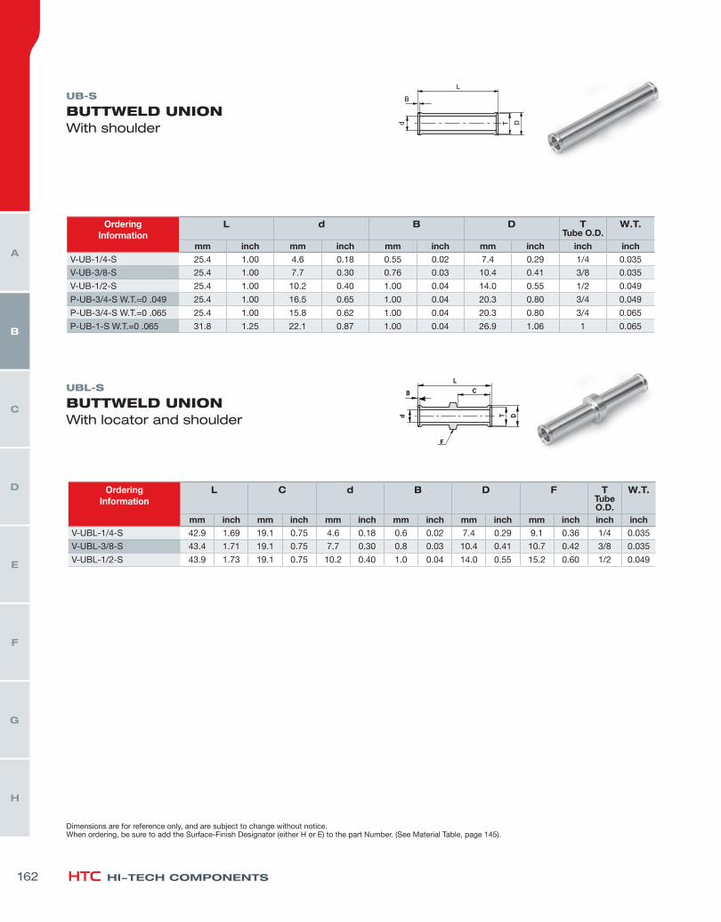
UB-S
BUTTWELD UNIONWith shoulder
Dimensions are for reference only, and are subject to change without notice.When ordering, be sure to add the Surface-Finish Designator (either H or E) to the part Number. (See Material Table, page 145).
OrderingInformation
L d B D TTube O.D.
W.T.
mm inch mm inch mm inch mm inch inch inchV-UB-1/4-S 25.4 1.00 4.6 0.18 0.55 0.02 7.4 0.29 1/4 0.035
V-UB-3/8-S 25.4 1.00 7.7 0.30 0.76 0.03 10.4 0.41 3/8 0.035
V-UB-1/2-S 25.4 1.00 10.2 0.40 1.00 0.04 14.0 0.55 1/2 0.049
P-UB-3/4-S W.T.=0 .049 25.4 1.00 16.5 0.65 1.00 0.04 20.3 0.80 3/4 0.049
P-UB-3/4-S W.T.=0 .065 25.4 1.00 15.8 0.62 1.00 0.04 20.3 0.80 3/4 0.065
P-UB-1-S W.T.=0 .065 31.8 1.25 22.1 0.87 1.00 0.04 26.9 1.06 1 0.065
UBL-S
BUTTWELD UNIONWith locator and shoulder
OrderingInformation
L C d B D F TTube O.D.
W.T.
mm inch mm inch mm inch mm inch mm inch mm inch inch inchV-UBL-1/4-S 42.9 1.69 19.1 0.75 4.6 0.18 0.6 0.02 7.4 0.29 9.1 0.36 1/4 0.035
V-UBL-3/8-S 43.4 1.71 19.1 0.75 7.7 0.30 0.8 0.03 10.4 0.41 10.7 0.42 3/8 0.035
V-UBL-1/2-S 43.9 1.73 19.1 0.75 10.2 0.40 1.0 0.04 14.0 0.55 15.2 0.60 1/2 0.049
162
H
G
F
E
D
C
B
A
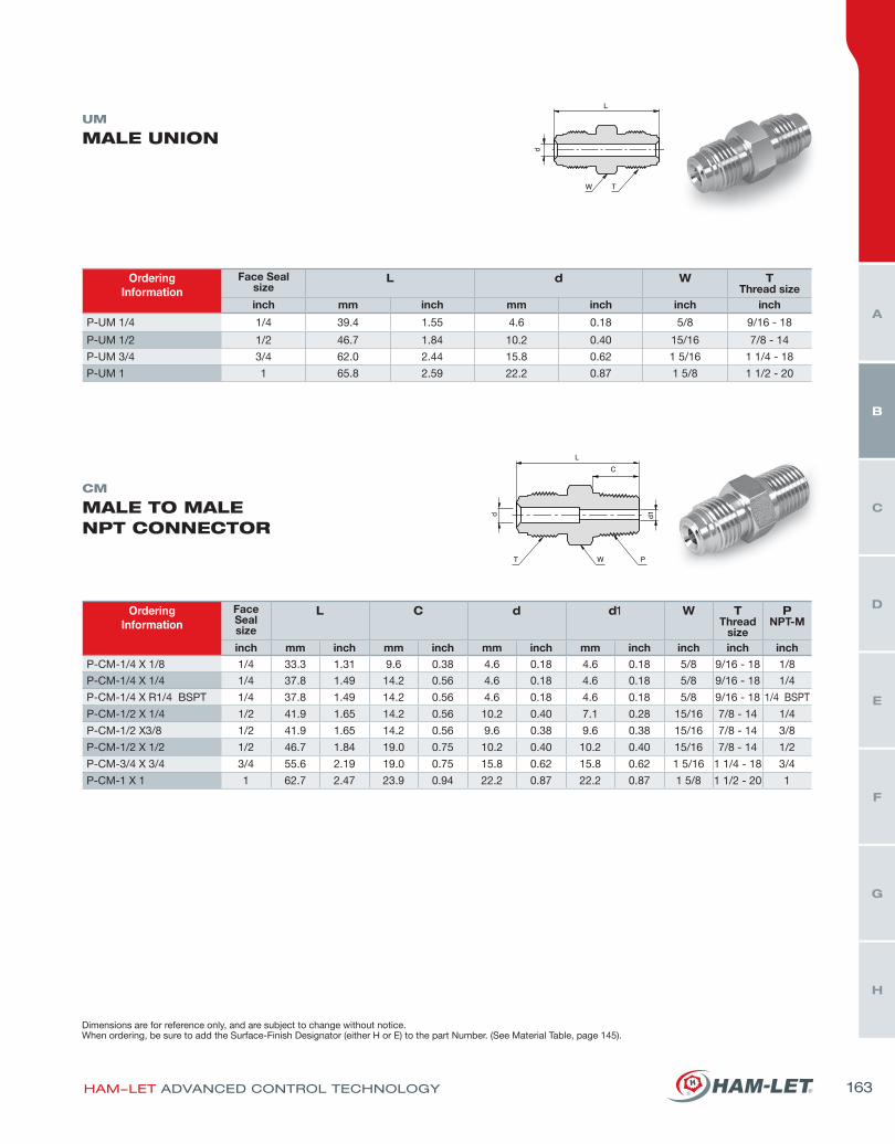
UM
MALE UNION
OrderingInformation
Face Sealsize
L d W TThread size
inch mm inch mm inch inch inch
P-UM 1/4 1/4 39.4 1.55 4.6 0.18 5/8 9/16 - 18
P-UM 1/2 1/2 46.7 1.84 10.2 0.40 15/16 7/8 - 14
P-UM 3/4 3/4 62.0 2.44 15.8 0.62 1 5/16 1 1/4 - 18
P-UM 1 1 65.8 2.59 22.2 0.87 1 5/8 1 1/2 - 20
Dimensions are for reference only, and are subject to change without notice.When ordering, be sure to add the Surface-Finish Designator (either H or E) to the part Number. (See Material Table, page 145).
CM
MALE TO MALENPT CONNECTOR
OrderingInformation
Face Sealsize
L C d d1 W TThread
size
PNPT-M
inch mm inch mm inch mm inch mm inch inch inch inchP-CM-1/4 X 1/8 1/4 33.3 1.31 9.6 0.38 4.6 0.18 4.6 0.18 5/8 9/16 - 18 1/8
P-CM-1/4 X 1/4 1/4 37.8 1.49 14.2 0.56 4.6 0.18 4.6 0.18 5/8 9/16 - 18 1/4
P-CM-1/4 X R1/4 BSPT 1/4 37.8 1.49 14.2 0.56 4.6 0.18 4.6 0.18 5/8 9/16 - 18 1/4 BSPT
P-CM-1/2 X 1/4 1/2 41.9 1.65 14.2 0.56 10.2 0.40 7.1 0.28 15/16 7/8 - 14 1/4
P-CM-1/2 X3/8 1/2 41.9 1.65 14.2 0.56 9.6 0.38 9.6 0.38 15/16 7/8 - 14 3/8
P-CM-1/2 X 1/2 1/2 46.7 1.84 19.0 0.75 10.2 0.40 10.2 0.40 15/16 7/8 - 14 1/2
P-CM-3/4 X 3/4 3/4 55.6 2.19 19.0 0.75 15.8 0.62 15.8 0.62 1 5/16 1 1/4 - 18 3/4
P-CM-1 X 1 1 62.7 2.47 23.9 0.94 22.2 0.87 22.2 0.87 1 5/8 1 1/2 - 20 1
HAM-LET ADVANCED CONTROL TECHNOLOGY 163
H
G
F
E
D
C
B
A
HI-TECH COMPONENTS
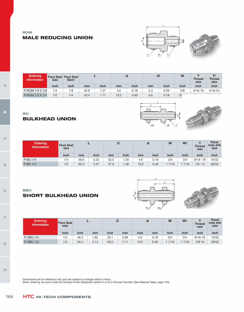
RUM
MALE REDUCING UNION
BU
BULKHEAD UNION
SBU
SHORT BULKHEAD UNION
OrderingInformation
Face Sealsize
Face SealSize1
L d d1 W TThread
size
T1Thread
sizeinch inch mm inch mm inch mm inch inch inch inch
P-RUM 1/4 X 1/8 1/4 1/8 34.8 1.37 4.6 0.18 2.4 0.09 5/8 9/16-18 5/16-24
P-RUM 1/2 X 1/4 1/2 1/4 43.4 1.71 10.2 0.40 4.6 0.18 15/16 7/8-1/4 9/16 -18
OrderingInformation
Face Sealsize
L C d W W1 TThread
size
Panel hole drill
size
inch inch mm inch mm inch mm inch inch inch inch
P-SBU 1/4 1/4 46.2 1.82 25.1 0.99 4.6 0.18 3/4 3/4 9/16-18 19/32
P-SBU 1/2 1/2 54.4 2.14 28.2 1.11 10.2 0.40 1 1/16 1 1/16 7/8-14 29/32
OrderingInformation
Face Sealsize
L C d W W1 TThread
size
Panel hole drill
size
inch mm inch mm inch mm inch inch inch inch inchP-BU 1/4 1/4 56.6 2.23 33.0 1.30 4.6 0.18 3/4 3/4 9/16 -18 19/32
P-BU 1/2 1/2 65.3 2.57 37.6 1.48 10.2 0.40 1 1/16 1 1/16 7/8 -14 29/32
Dimensions are for reference only, and are subject to change without notice.When ordering, be sure to add the Surface-Finish Designator (either H or E) to the part Number. (See Material Table, page 145).
164
H
G
F
E
D
C
B
A
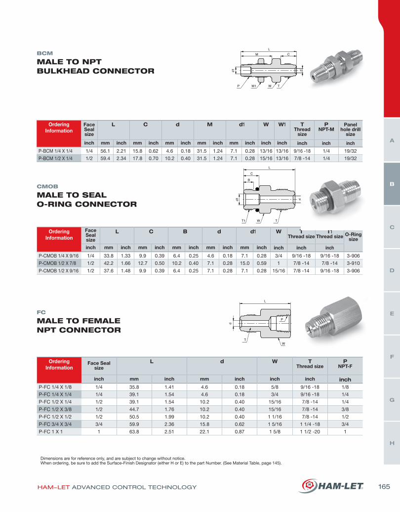
BCM
MALE TO NPT BULKHEAD CONNECTOR
CMOB
MALE TO SEAL O-RING CONNECTOR
FC
MALE TO FEMALE NPT CONNECTOR
OrderingInformation
Face Seal size
L C d M d1 W W1 TThread
size
PNPT-M
Panel hole drill
size
inch mm inch mm inch mm inch mm inch mm inch inch inch inch inch inch
P-BCM 1/4 X 1/4 1/4 56.1 2.21 15.8 0.62 4.6 0.18 31.5 1.24 7.1 0.28 13/16 13/16 9/16 -18 1/4 19/32
P-BCM 1/2 X 1/4 1/2 59.4 2.34 17.8 0.70 10.2 0.40 31.5 1.24 7.1 0.28 15/16 13/16 7/8 -14 1/4 19/32
OrderingInformation
Face Sealsize
L C B d d1 W TThread size
T1Thread size O-Ring
size
inch mm inch mm inch mm inch mm inch mm inch inch inch inch
P-CMOB 1/4 X 9/16 1/4 33.8 1.33 9.9 0.39 6.4 0.25 4.6 0.18 7.1 0.28 3/4 9/16 -18 9/16 -18 3-906
P-CMOB 1/2 X 7/8 1/2 42.2 1.66 12.7 0.50 10.2 0.40 7.1 0.28 15.0 0.59 1 7/8 -14 7/8 -14 3-910
P-CMOB 1/2 X 9/16 1/2 37.6 1.48 9.9 0.39 6.4 0.25 7.1 0.28 7.1 0.28 15/16 7/8 -14 9/16 -18 3-906
OrderingInformation
Face Sealsize
L d W TThread size
PNPT-F
inch mm inch mm inch inch inch inchP-FC 1/4 X 1/8 1/4 35.8 1.41 4.6 0.18 5/8 9/16 -18 1/8
P-FC 1/4 X 1/4 1/4 39.1 1.54 4.6 0.18 3/4 9/16 -18 1/4
P-FC 1/2 X 1/4 1/2 39.1 1.54 10.2 0.40 15/16 7/8 -14 1/4
P-FC 1/2 X 3/8 1/2 44.7 1.76 10.2 0.40 15/16 7/8 -14 3/8
P-FC 1/2 X 1/2 1/2 50.5 1.99 10.2 0.40 1 1/16 7/8 -14 1/2
P-FC 3/4 X 3/4 3/4 59.9 2.36 15.8 0.62 1 5/16 1 1/4 -18 3/4
P-FC 1 X 1 1 63.8 2.51 22.1 0.87 1 5/8 1 1/2 -20 1
Dimensions are for reference only, and are subject to change without notice.When ordering, be sure to add the Surface-Finish Designator (either H or E) to the part Number. (See Material Table, page 145).
HAM-LET ADVANCED CONTROL TECHNOLOGY 165
H
G
F
E
D
C
B
A
HI-TECH COMPONENTS
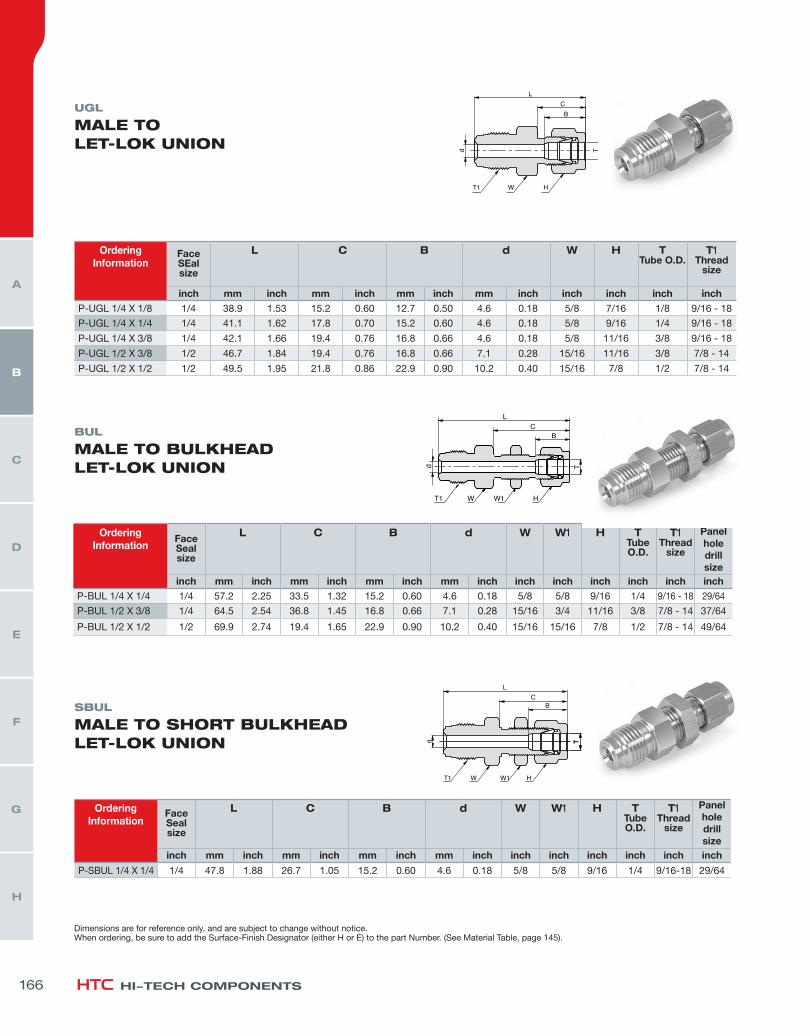
UGL
MALE TO LET-LOK UNION
BUL
MALE TO BULKHEAD LET-LOK UNION
SBUL
MALE TO SHORT BULKHEAD LET-LOK UNION
OrderingInformation
Face SEalsize
L C B d W H TTube O.D.
T1Thread
size
inch mm inch mm inch mm inch mm inch inch inch inch inchP-UGL 1/4 X 1/8 1/4 38.9 1.53 15.2 0.60 12.7 0.50 4.6 0.18 5/8 7/16 1/8 9/16 - 18
P-UGL 1/4 X 1/4 1/4 41.1 1.62 17.8 0.70 15.2 0.60 4.6 0.18 5/8 9/16 1/4 9/16 - 18
P-UGL 1/4 X 3/8 1/4 42.1 1.66 19.4 0.76 16.8 0.66 4.6 0.18 5/8 11/16 3/8 9/16 - 18
P-UGL 1/2 X 3/8 1/2 46.7 1.84 19.4 0.76 16.8 0.66 7.1 0.28 15/16 11/16 3/8 7/8 - 14
P-UGL 1/2 X 1/2 1/2 49.5 1.95 21.8 0.86 22.9 0.90 10.2 0.40 15/16 7/8 1/2 7/8 - 14
OrderingInformation
Face Sealsize
L C B d W W1 H TTube O.D.
T1Thread
size
Panel holedrill size
inch mm inch mm inch mm inch mm inch inch inch inch inch inch inchP-BUL 1/4 X 1/4 1/4 57.2 2.25 33.5 1.32 15.2 0.60 4.6 0.18 5/8 5/8 9/16 1/4 9/16 - 18 29/64
P-BUL 1/2 X 3/8 1/4 64.5 2.54 36.8 1.45 16.8 0.66 7.1 0.28 15/16 3/4 11/16 3/8 7/8 - 14 37/64
P-BUL 1/2 X 1/2 1/2 69.9 2.74 19.4 1.65 22.9 0.90 10.2 0.40 15/16 15/16 7/8 1/2 7/8 - 14 49/64
OrderingInformation
Face Sealsize
L C B d W W1 H TTube O.D.
T1Thread
size
Panel holedrill size
inch mm inch mm inch mm inch mm inch inch inch inch inch inch inch
P-SBUL 1/4 X 1/4 1/4 47.8 1.88 26.7 1.05 15.2 0.60 4.6 0.18 5/8 5/8 9/16 1/4 9/16-18 29/64
Dimensions are for reference only, and are subject to change without notice.When ordering, be sure to add the Surface-Finish Designator (either H or E) to the part Number. (See Material Table, page 145).
166
H
G
F
E
D
C
B
A
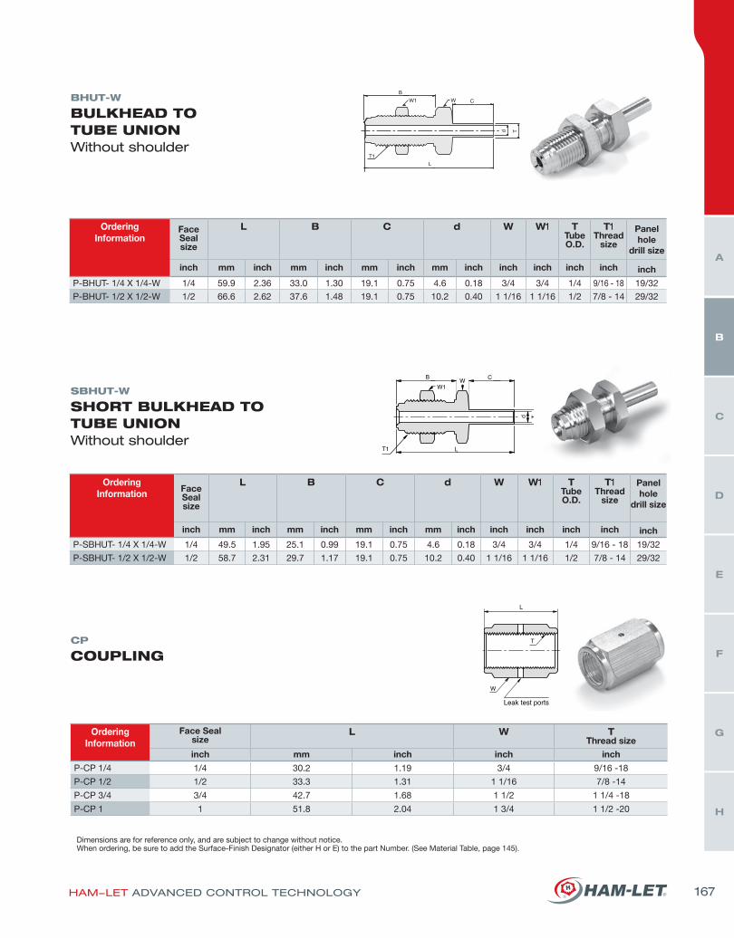
BHUT-W
BULKHEAD TO TUBE UNIONWithout shoulder
SBHUT-W
SHORT BULKHEAD TO TUBE UNIONWithout shoulder
CP
COUPLING
OrderingInformation
Face Sealsize
L B C d W W1 TTube O.D.
T1Thread
size
Panel hole
drill size
inch mm inch mm inch mm inch mm inch inch inch inch inch inch
P-BHUT- 1/4 X 1/4-W 1/4 59.9 2.36 33.0 1.30 19.1 0.75 4.6 0.18 3/4 3/4 1/4 9/16 - 18 19/32
P-BHUT- 1/2 X 1/2-W 1/2 66.6 2.62 37.6 1.48 19.1 0.75 10.2 0.40 1 1/16 1 1/16 1/2 7/8 - 14 29/32
OrderingInformation Face
Sealsize
L B C d W W1 TTube O.D.
T1Thread
size
Panel hole
drill size
inch mm inch mm inch mm inch mm inch inch inch inch inch inch
P-SBHUT- 1/4 X 1/4-W 1/4 49.5 1.95 25.1 0.99 19.1 0.75 4.6 0.18 3/4 3/4 1/4 9/16 - 18 19/32
P-SBHUT- 1/2 X 1/2-W 1/2 58.7 2.31 29.7 1.17 19.1 0.75 10.2 0.40 1 1/16 1 1/16 1/2 7/8 - 14 29/32
OrderingInformation
Face Sealsize
L W TThread size
inch mm inch inch inch
P-CP 1/4 1/4 30.2 1.19 3/4 9/16 -18
P-CP 1/2 1/2 33.3 1.31 1 1/16 7/8 -14
P-CP 3/4 3/4 42.7 1.68 1 1/2 1 1/4 -18
P-CP 1 1 51.8 2.04 1 3/4 1 1/2 -20
Dimensions are for reference only, and are subject to change without notice.When ordering, be sure to add the Surface-Finish Designator (either H or E) to the part Number. (See Material Table, page 145).
HAM-LET ADVANCED CONTROL TECHNOLOGY 167
H
G
F
E
D
C
B
A
HI-TECH COMPONENTS
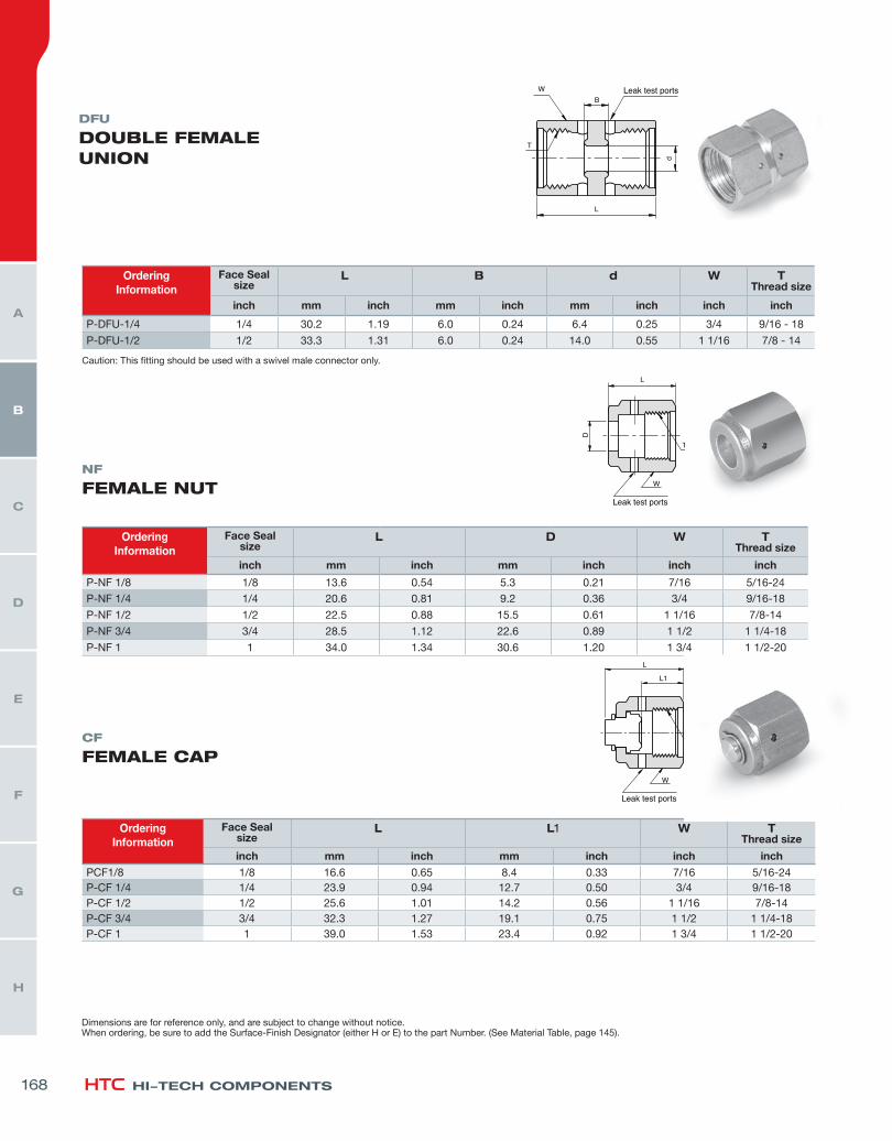
DFU
DOUBLE FEMALEUNION
NF
FEMALE NUT
CF
FEMALE CAP
OrderingInformation
Face Sealsize
L D W TThread size
inch mm inch mm inch inch inch
P-NF 1/8 1/8 13.6 0.54 5.3 0.21 7/16 5/16-24
P-NF 1/4 1/4 20.6 0.81 9.2 0.36 3/4 9/16-18
P-NF 1/2 1/2 22.5 0.88 15.5 0.61 1 1/16 7/8-14
P-NF 3/4 3/4 28.5 1.12 22.6 0.89 1 1/2 1 1/4-18
P-NF 1 1 34.0 1.34 30.6 1.20 1 3/4 1 1/2-20
OrderingInformation
Face Sealsize
L L1 W TThread size
inch mm inch mm inch inch inchPCF1/8 1/8 16.6 0.65 8.4 0.33 7/16 5/16-24P-CF 1/4 1/4 23.9 0.94 12.7 0.50 3/4 9/16-18P-CF 1/2 1/2 25.6 1.01 14.2 0.56 1 1/16 7/8-14P-CF 3/4 3/4 32.3 1.27 19.1 0.75 1 1/2 1 1/4-18P-CF 1 1 39.0 1.53 23.4 0.92 1 3/4 1 1/2-20
OrderingInformation
Face Sealsize
L B d W TThread size
inch mm inch mm inch mm inch inch inch
P-DFU-1/4 1/4 30.2 1.19 6.0 0.24 6.4 0.25 3/4 9/16 - 18
P-DFU-1/2 1/2 33.3 1.31 6.0 0.24 14.0 0.55 1 1/16 7/8 - 14
Caution: This fitting should be used with a swivel male connector only.
Dimensions are for reference only, and are subject to change without notice.When ordering, be sure to add the Surface-Finish Designator (either H or E) to the part Number. (See Material Table, page 145).
168
H
G
F
E
D
C
B
A
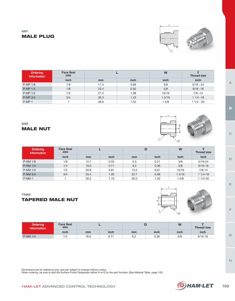
NM
MALE NUT
MP
MALE PLUG
TNM
TAPERED MALE NUT
OrderingInformation
Face Sealsize
L W TThread size
inch mm inch inch inch
P-MP 1/8 1/8 17.3 0.68 3/8 5/16 - 24
P-MP 1/4 1/8 23.4 0.92 5/8 9/16 -18
P-MP 1/2 1/2 27.4 1.08 15/16 7/8 -14
P-MP 3/4 3/4 36.3 1.43 1 5/16 1 1/4 -18
P-MP 1 1 38.6 1.52 1 5/8 1 1/2 - 20
OrderingInformation
Face Sealsize
L D W TThread size
inch mm inch mm inch inch inch
P-NM 1/8 1/8 12.7 0.50 5.3 0.21 3/8 5/16-24P-NM 1/4 1/4 18.0 0.71 9.2 0.36 5/8 9/16-18
P-NM 1/2 1/2 20.6 0.81 15.5 0.61 15/16 7/8-14
P-NM 3/4 3/4 25.4 1.00 22.7 0.89 1 5/16 1 1/4-18
P-NM 1 1 30.2 1.19 30.5 1.20 1 5/8 1 1/2-20
OrderingInformation
Face Sealsize
L D W TThread size
inch mm inch mm inch inch inch
P-NM 1/4 1/4 18.0 0.71 9.2 0.36 5/8 9/16-18
Dimensions are for reference only, and are subject to change without notice.When ordering, be sure to add the Surface-Finish Designator (either H or E) to the part Number. (See Material Table, page 145).
HAM-LET ADVANCED CONTROL TECHNOLOGY 169
H
G
F
E
D
C
B
A
HI-TECH COMPONENTS
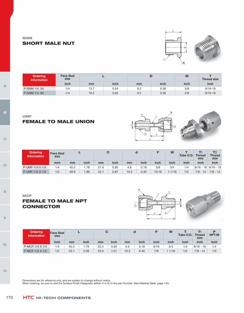
SNM
SHORT MALE NUT
UMF
FEMALE TO MALE UNION
MCF
FEMALE TO MALE NPT CONNECTOR
OrderingInformation
Face Sealsize
L C d F W TTube O.D.
T1Thread
size
T2Thread
sizeinch mm inch mm inch mm inch inch inch inch inch inch
P-UMF-1/4 X 1/4 1/4 45.2 1.78 21.6 0.85 4.6 0.18 5/8 3/4 1/4 9/16 - 18 9/16 - 18
P-UMF-1/2 X 1/2 1/2 49.8 1.96 22.1 0.87 10.2 0.40 15/16 1-1/16 1/2 7/8 - 14 7/8 - 14
OrderingInformation
Face Sealsize
L C d F W TTube O.D.
T1Thread
size
PNPT-M
inch mm inch mm inch mm inch inch inch inch inch inch
P-MCF-1/4 X 1/4 1/4 45.5 1.79 23.4 0.92 4.6 0.18 9/16 3/4 1/4 9/16 - 18 1/4
P-MCF-1/2 X 1/2 1/2 53.1 2.09 25.6 1.01 10.2 0.40 7/8 1 1/16 1/2 7/8 - 14 1/2
OrderingInformation
Face Sealsize
L D W TThread size
inch mm inch mm inch inch inch
P-SNM 1/4 .54 1/4 13.7 0.54 9.2 0.36 5/8 9/16-18
P-SNM 1/4 .65 1/4 16.5 0.65 9.2 0.36 5/8 9/16-18
Dimensions are for reference only, and are subject to change without notice.When ordering, be sure to add the Surface-Finish Designator (either H or E) to the part Number. (See Material Table, page 145).
170
H
G
F
E
D
C
B
A
OrderingInformation
Face Sealsize
L d W TTube O.D.
T1Thread size
inch mm inch mm inch inch inch inch
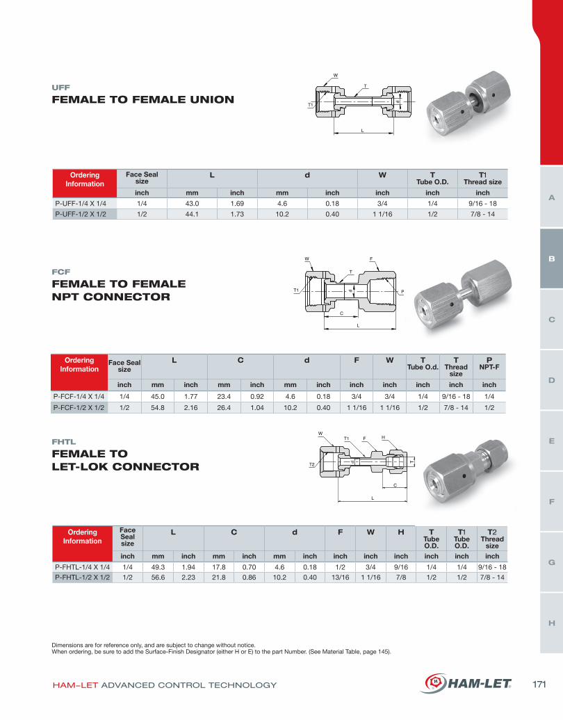
P-UFF-1/4 X 1/4 1/4 43.0 1.69 4.6 0.18 3/4 1/4 9/16 - 18
P-UFF-1/2 X 1/2 1/2 44.1 1.73 10.2 0.40 1 1/16 1/2 7/8 - 14
UFF
FEMALE TO FEMALE UNION
FCF
FEMALE TO FEMALE NPT CONNECTOR
FHTL
FEMALE TO LET-LOK CONNECTOR
OrderingInformation
Face Sealsize
L C d F W TTube O.d.
TThread
size
PNPT-F
inch mm inch mm inch mm inch inch inch inch inch inch
P-FCF-1/4 X 1/4 1/4 45.0 1.77 23.4 0.92 4.6 0.18 3/4 3/4 1/4 9/16 - 18 1/4
P-FCF-1/2 X 1/2 1/2 54.8 2.16 26.4 1.04 10.2 0.40 1 1/16 1 1/16 1/2 7/8 - 14 1/2
OrderingInformation
Face Sealsize
L C d F W H TTube O.D.
T1Tube O.D.
T2Thread
size
inch mm inch mm inch mm inch inch inch inch inch inch inch
P-FHTL-1/4 X 1/4 1/4 49.3 1.94 17.8 0.70 4.6 0.18 1/2 3/4 9/16 1/4 1/4 9/16 - 18
P-FHTL-1/2 X 1/2 1/2 56.6 2.23 21.8 0.86 10.2 0.40 13/16 1 1/16 7/8 1/2 1/2 7/8 - 14
Dimensions are for reference only, and are subject to change without notice.When ordering, be sure to add the Surface-Finish Designator (either H or E) to the part Number. (See Material Table, page 145).
HAM-LET ADVANCED CONTROL TECHNOLOGY 171
H
G
F
E
D
C
B
A
HI-TECH COMPONENTS
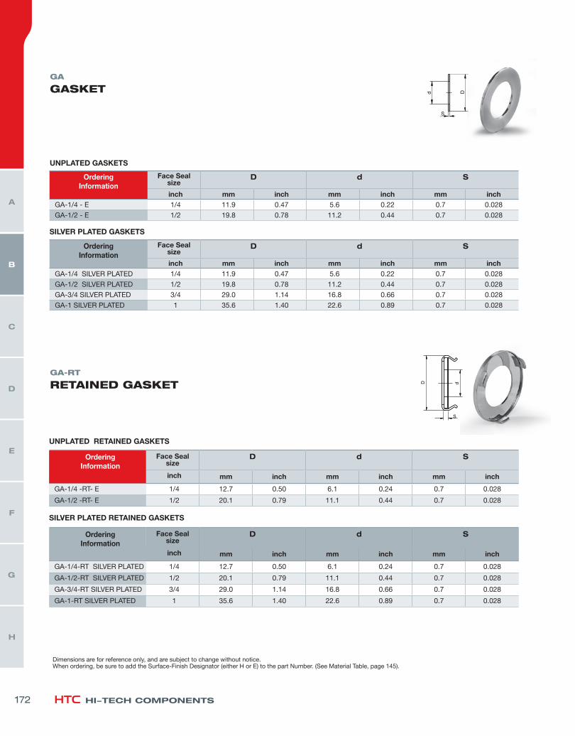
GA
GASKET
GA-RT
RETAINED GASKET
UNPLATED GASKETS
OrderingInformation
Face Sealsize
D d S
inch mm inch mm inch mm inchGA-1/4 - E 1/4 11.9 0.47 5.6 0.22 0.7 0.028
GA-1/2 - E 1/2 19.8 0.78 11.2 0.44 0.7 0.028
SILVER PLATED GASKETS
OrderingInformation
Face Sealsize
D d S
inch mm inch mm inch mm inchGA-1/4 SILVER PLATED 1/4 11.9 0.47 5.6 0.22 0.7 0.028
GA-1/2 SILVER PLATED 1/2 19.8 0.78 11.2 0.44 0.7 0.028
GA-3/4 SILVER PLATED 3/4 29.0 1.14 16.8 0.66 0.7 0.028
GA-1 SILVER PLATED 1 35.6 1.40 22.6 0.89 0.7 0.028
UNPLATED RETAINED GASKETS
OrderingInformation
Face Sealsize
D d S
inch mm inch mm inch mm inch
GA-1/4 -RT- E 1/4 12.7 0.50 6.1 0.24 0.7 0.028
GA-1/2 -RT- E 1/2 20.1 0.79 11.1 0.44 0.7 0.028
SILVER PLATED RETAINED GASKETS
OrderingInformation
Face Sealsize
D d S
inch mm inch mm inch mm inch
GA-1/4-RT SILVER PLATED 1/4 12.7 0.50 6.1 0.24 0.7 0.028
GA-1/2-RT SILVER PLATED 1/2 20.1 0.79 11.1 0.44 0.7 0.028
GA-3/4-RT SILVER PLATED 3/4 29.0 1.14 16.8 0.66 0.7 0.028
GA-1-RT SILVER PLATED 1 35.6 1.40 22.6 0.89 0.7 0.028
Dimensions are for reference only, and are subject to change without notice.When ordering, be sure to add the Surface-Finish Designator (either H or E) to the part Number. (See Material Table, page 145).
172
H
G
F
E
D
C
B
A
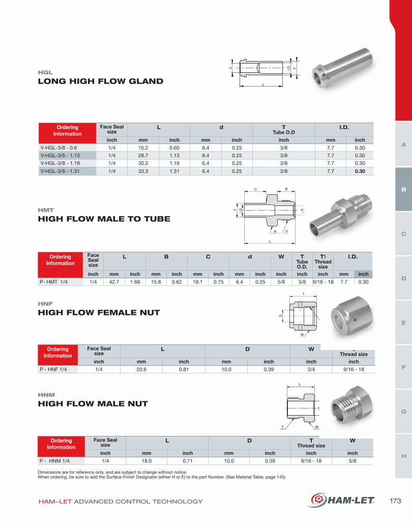
HGL
LONG HIGH FLOW GLAND
OrderingInformation
Face Sealsize
L d TTube O.D
I.D.
inch mm inch mm inch inch mm inch
V-HGL-3/8 - 0.6 1/4 15.2 0.60 6.4 0.25 3/8 7.7 0.30
V-HGL-3/8 - 1.13 1/4 28.7 1.13 6.4 0.25 3/8 7.7 0.30
V-HGL-3/8 - 1.19 1/4 30.2 1.19 6.4 0.25 3/8 7.7 0.30
V-HGL-3/8 - 1.31 1/4 33.3 1.31 6.4 0.25 3/8 7.7 0.30
HMT
HIGH FLOW MALE TO TUBE
HNF
HIGH FLOW FEMALE NUT
HNM
HIGH FLOW MALE NUT
OrderingInformation
Face Sealsize
L B C d W TTube O.D.
T1Thread
size
I.D.
inch mm inch mm inch mm inch mm inch inch inch inch mm inch
P- HMT 1/4 1/4 42.7 1.68 15.8 0.62 19.1 0.75 6.4 0.25 5/8 3/8 9/16 - 18 7.7 0.30
OrderingInformation
Face Sealsize
L D W TThread size
inch mm inch mm inch inch inch
P - HNF 1/4 1/4 20.6 0.81 10.0 0.39 3/4 9/16 - 18
OrderingInformation
Face Sealsize
L D TThread size
W
inch mm inch mm inch inch inch
P - HNM 1/4 1/4 18.0 0.71 10.0 0.39 9/16 - 18 5/8
Dimensions are for reference only, and are subject to change without notice.When ordering, be sure to add the Surface-Finish Designator (either H or E) to the part Number. (See Material Table, page 145).
HAM-LET ADVANCED CONTROL TECHNOLOGY 173
H
G
F
E
D
C
B
A
HI-TECH COMPONENTS
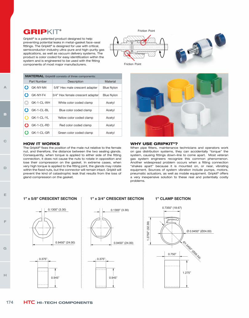
Gripkit® is a patented product designed to help preventing potential leaks in metal-gasket face-seal fittings. The Gripkit® is designed for use with critical, semiconductor-industry ultra-pure and high-purity gas applications, as well as vacuum delivery systems. The product is color coded for easy identification within the system and is engineered to be used with the fitting components of most major manufacturers.
HOW IT WORKSThe Gripkit® fixes the position of the male nut relative to the female nut, and therefore, the distance between the two sealing glands. Consequently, when torque is applied to either side of the fitting connection, it does not cause the nuts to rotate in opposition and lose their compression on the gasket. In extreme cases, when very high torque is applied to the fitting joint, the glands may rotate within the fixed nuts, but the connector will remain intact. Gripkit will prevent the kind of catastrophic leak that results from the loss of gland compression on the gasket.
WHY USE GRIPKIT®?When pipe fitters, maintenance technicians and operators work on gas distribution systems, they can accidentally “torque” the system, causing fittings down-line to come apart. Most veteran gas system engineers recognize this common phenomenon. Another widespread problem occurs when a fitting connection “shakes apart” because it is mounted on, or near, vibrating equipment. Sources of system vibration include pumps, motors, pneumatic actuators, as well as mobile equipment. Gripkit® offers a very inexpensive solution to these real and potentially costly problems.
MATERIAL Gripkit® consists of three components:
Part Number Description Material
GK-NY-M4 5/8” Hex male crescent adapter Blue Nylon
GK-NY-F4 3/4” Hex female crescent adapter Blue Nylon
GK-1-CL-WH White color coded clamp Acetyl
GK-1-CL-BL Blue color coded clamp Acetyl
GK-1-CL-YL Yellow color coded clamp Acetyl
GK-1-CL-RD Red color coded clamp Acetyl
GK-1-CL-GR Green color coded clamp Acetyl
1” x 3/4” CRESCENT SECTION1” x 5/8” CRESCENT SECTION 1” CLAMP SECTION
®
174
H
G
F
E
D
C
B
A