hi-6 cd ignition - crane cams cd ignition with rev limiter part numbers 6000-6400, 6000-6424, and...
TRANSCRIPT

11/10 9000-6400A111/10 9000-6400A11
Installation Instructions for
HI-6 CD IGNITIONwith Rev LimiterPart Numbers 6000-6400, 6000-6424, and 6000-6466
For more information, see www.cranecams.comCAUTION: READ INSTRUCTIONS CAREFULLY BEFORE STARTING INSTALLATION.
READ THIS BEFORE YOU BEGIN!Before proceeding with the HI-6 installation, read the introduc-tory material below so that you will understand the basic fea-tures and operation of the unit. The installation instructions are organized by application; use the Applications Index to find the appropriate section for your vehicle. For hookup of optional TRC-2 Timing Retard Control Part Number 6000-6425, additional information is provided in the TRC-2 section start-ing on page 11.
CAUTION: READ THE FOLLOWING CAREFULLY:• HI-6R(6000-6400)andHI-6DSR(6000-6424)CDignitionsareprimarilyintendedformagnetictriggerapplications.HI-6TRC(6000-6466) isakit that includes theHI-6RandTRC-2 tim-ingretardcontrol.TheseHI-6unitsarefullyencapsulatedwithurethaneandcapableofoperationinsevereenvironments.
• TheseHI-6 units now includewire harnesseswithWeatherPackconnectors.Please note that cutting off any Weather Pack connectors voids the HI-6 warranty!
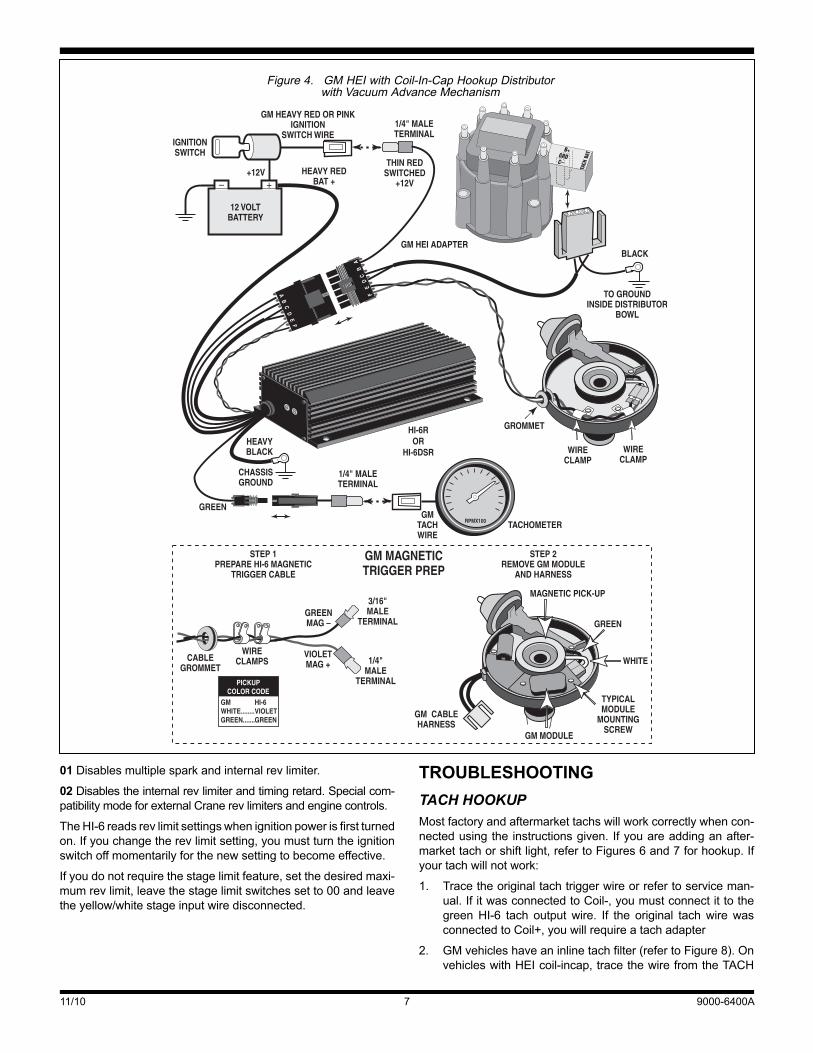
• Makesurethatalloriginalequipmentwiresaredisconnectedfromcoil.GMcoil-in-capHEI: Installblackgroundwire fromcap connector to a ground point inside distributor bowl asshowninFigure4.
Daytona Beach, FL 32117www.cranecams.com / Phone: 866-388-5120 / Fax: 608-627-0480
• Tapeupanyunusedwiresaftercompletingtheinstallation.Ifthemagnetic trigger leadsarenotused, cut short and tapeupeachleadseparately.Ifthewhitepointstriggerwireisnotused, tape itup. Ifunused trigger leadsshort togetheror toground,theHI-6willnotrun.
INTRODUCTIONThe Crane Cams HI-6 is an advanced capacitive discharge(CD)typeignitionsystemintendedforracingandperformancestreetvehicles.TheHI-6is50statesstreetlegal(CaliforniaAirResourcesBoardE.O.D-225-52andD-225-63 for 1995andpriornon-OBDIIvehicles)andcanbeinstalledinmostvehicles.Triggersourcesinclude:
• Magneticpickupdistributorandcranktrigger
• Electronicignitionmodule
• Pointsdistributor
MULTIPLE SPARK Under lowRPMcrankingconditions, theHI-6generatesup to12 sparks. This assures quick starting even under the mostadverseconditions.Atidleandcruise,thenumberofsparksfiredisadjusted tomaintaina totalsparkdurationofapproximately20degrees(crankshaft),assuringsmoothidle,improvedthrottleresponse,andeliminatingtheleansurgecharacteristicofsomelatemodelemissioncontrolledvehicles.Above3,000RPM,theHI-6 generates a single powerful spark with many times thesparkgapcurrentofmostcompetitivesystems.
DIGITAL SEQUENTIAL REV LIMITERAllHI-6unitshaveanexternallyactivatedstagerevlimiterthatcanbedigitallysetfrom600to9,900RPMin100RPMincrementsviarotaryswitches.Theyellow/whitewire(yellowwiththinwhitestripe)isusedtoactivatethestagerevlimiter.Sincemostlatemodelvehi-cleshaveon-boardenginecontrolcomputersthatsetasafemaxi-mumrevlimit,thestagelimitfeatureontheHI-6canbeusedforselectingalowerrevlimitfordragracing.
APPLICATIONS INDEX Late Model Computer Controlled Vehicles with Stock Electronic Ignition ...........................Page 5(most 1981 and later cars and 1986 and later lighttruckswithOEelectronic ignitionandenginecontrolcomputer, and European vehicles with Bosch HallEffectignition)
Earlier Electronic Ignition Systems Without Computer Control (Magnetic Triggered Systems) ..........................Page 6(most 1974–1980 cars and 1974–1985 light truckswithmagneticpickupdistributorandanyvehicleswithaftermarket crank trigger. Includes detailed hookupsforGMcoil-in-capandexternal coilHEIwith vacuumadvancedistributor.)
®
CAUTION: The HI-6 is not compatible with any odd firing engines or distributorless ignition systems.

11/10 9000-6400A2
COIL COMPATIBILITY Mostoriginalequipment(OE)coilsarecompatiblewiththeHI-6.WerecommendtheCraneCamsLX92orPS92.Thesecoilsarecapableofcontinuousoperationat8,500RPMand85degreesC(185degreeF)ambienttemperature.
SPARK PLUGS AND WIRES Donotusesolidcorewire,asthiscangenerateelectricalnoisethatmayinterferewiththeHI-6orotheronboardcomputerandradioequipment.Donotusehighresistancecarbonwire,asthismayburnoutfromthehighenergylevels.Optimumwireresis-tanceislessthan800ohmsperfoot.
Foroptimumperformance in racingapplicationsuseonlynon-resistor spark plugs. Resistor spark plugs are required for allstreet applications unless recommended otherwise by vehiclemanufacturer. Recommended plug gap is .045” for normallyaspiratedenginesusedforoff-roadracing.
TheHI-6DSR(6000-6424)hasatwostagerevlimiter.Anaddi-tionalsetofrotaryswitchessetsthemaximumrev limitontheHI-6DSRfrom600to9,900RPMin100RPMincrements.
Thestagelimitisactivatedbyapplying+12Vtotheyellow/whitewire.Ifthestagelimitisnotactivated,themaximumrevlimitisselected.
The rev limiter can be set to operate with 4, 6 or 8 cylinderengines.Accuracyis+/-30RPM.Therevlimiterisnotcompat-iblewithanyoddfiringengines.
TheHI-6utilizesasequentialfiringprogramtoequalizecylinderfiringattherevlimit.WhenengineRPMexceedstherevlimit,fir-ingstops.TheHI-6countsthenumberofcylinderfiringsthatareskipped.OnceRPMdropsbelowtherevlimit,firingisresumedwhen thecount reachesanoddnumber. If theengine isheldagainsttherevlimit,RPMwillstaywithinanarrowband.Allcylin-derswillbefiredequallyinrotation.Fuelloadingandplugfoulingwillbegreatlyreduced.Sequentialfiringalsominimizesharmon-icsandvibrationsthatcanstressengineanddrivetrainparts.
RETARD CAPABILITY All HI-6 units have a timing retard capability. Several retardmodes are supported including boost proportional retard. Anoptional TRC-2 Timing Retard Control module (6000-6425) isrequiredtomakeuseofthetimingretardcapability.TheTRC-2attachestothebrown/whitewire(brownwiththinwhitestripe).RefertotheTRC-2sectionstartingonpage11fordetails.
TRIGGER RETARD COMPENSATION Magnetic pickups have an inherent retard characteristic. TheRISCmicrocontrollerwithintheHI-6automaticallycompensatesfor this retard characteristic andmaintains ignition timing con-stantwithin+/-.5degreethroughouttheentireRPMrange.
WARNING: High voltage is present at the coil primary and secondary terminals. Do not touch the coil while the engine is running. Do not connect any test equipment to the coil.
CAUTION: Use only low resistance spark plug wires such as Crane FireWire.
Figure 1. HI-6R and HI-6DSR Wire Identification

11/10 9000-6400A33
MOUNTING THE HI-6 PreferredmountinglocationfortheHI-6iswithinthepassengercompartment.IftheHI-6ismountedwithintheenginecompart-ment,makesurethatthemountinglocationisawayfromexhaustsystemheat,protectedfromwatersplash,andhasgoodairflowforcooling.Orientthecableexitdownward.
Whenyouhavepickedamountinglocation,makesurethatthewireharnesswillreachandthattherevlimitswitchesareacces-sible.Rubbershockmountsarerecommendedforracing.
BASIC HOOKUP This section provides generic hookup information that can beusedforapplicationsnotspecificallyreferencedintheApplica-tionsIndex.
Apartsbagwithhardwareandelectricalterminalsisprovidedforyourconvenience.Pleasereadtheinstallationinstructionsandstudythehookupdiagramsthoroughlybeforestarting.TheHI-6issuppliedwithWeatherPackconnectorsandanadapterhar-ness(refertoFigures2and3)thatfacilitateinstallationinmostvehicles.Please note that cutting off any Weather Pack con-nectors voids the HI-6 warranty. Allconnectionsmustbemadewithstrandedcopperwire.Crimpterminals are recommended over soldering, which can makewires brittle near the solder joint.Make sure all terminals arecleanand freeof corrosion.Scrapeoff paint, dirt, andgreasewhenmakingconnections toground.Youwill requirecommonhand tools including proper wire stripping andWeather Packcrimpingtools.LowcostWeatherPackcrimpingtoolssuchasPepBoysP/N85363areavailableatmanyautopartsstores.Donotattempttouseplierstocrimpterminals.
POWER AND GROUND Heavy RedConnecttoBattery+orbatterycableatstartersolenoid.Heavy BlackConnecttochassisground.Scrapeoffpainttoinsuregoodcontact.Use3/8”ringterminal.Donotlengthenthiswire.
COIL CABLE OrangeConnecttoCoil+.RemoveallotherwiresfromCoil+terminal.Black ConnecttoCoil-.RemoveallotherwiresfromCoilterminal.
IGNITION SWITCH Thin RedConnecttoswitched+12volts.Usuallythiswillcon-necttotheOEwirethatwasremovedfromCoil+.IftheOEwiringtoCoil+includedaballastresistor,theresistordoesnothavetoberemoved(seenotesforGMMagPulse).
CYLINDER SELECT BlueRefertoFigures2or3.UseamatingWeatherPackcon-nectorandlengthofwire:
8 cyl: Donotconnect.Installagreencavitypluginthemat-ingconnector(nowirerequired).
6 cyl: Connecttogroundwith1/4”ringterminal.
4 cyl: Connecttothinredswitched+12Vwire.
STAGE LIMIT INPUT Yellow/WhiteYellowwirewith thinwhitestripe.Refer toFigures2or3.ForP/N6000-6424withdualrevlimit,+12Vappliedtotheyellow/whitewireactivatesthestagerevlimit.Otherwisethemaxi-mumrevlimitisactive.ForP/N6000-6400withsinglerevlimit,youmustapply+12Vtotheyellowwhitewiretoactivatetherevlimit.Otherwisenorev limitingwilloccur.UseamatingWeatherPackconnector.Connectthewiretoanormallyopenswitchordirectto+12Vusinga3Mwiresplice.Ifyouarenotusingthisinput,youcaninstallagreencavitypluginthematingconnector.
RETARD INPUT Brown/White Brown wire with thin white stripe. Refer to theTRC-2sectionstartingonpage11.ConnecttotheTRC-2usingamatingWeatherPackconnector.Ifyouarenotusingthisinput,youcaninstallagreencavitypluginthematingconnector.
TACH OUTPUT GreenRefertoFigures2or3.ConnecttotachometerusingamatingWeatherPackconnector.Ifyouarenotusingthisinput,youcaninstallagreencavitypluginthematingconnector.Con-nectelectronic fuel injectionsandRPMactivatedsystems thatrequirea12volttachsignaltothiswire.Sometachsmayrequirean adapter. Refer to the Tach Hookup section on page 7 fordetails.
TRIGGER INPUTS Themagnetictriggercableisusedforallmagneticpickupdistrib-utorsandcranktriggersystems.Thewhite“points”triggerwireisusedfortriggeringfromignitionmodulesandpoints.Twistedpairtypecable(violetandgreenwires)isusedforthemagnetictrig-gercabletopreventelectricalnoise.Eitherthemagnetictriggeror“points”triggerinputwillbeused.Donotconnectboth.RefertoFigures2and3.
POINTS/MODULE TRIGGER INPUT White Connect to output of OE electronic ignition module orpoints.UsuallythiswillconnecttooneoftheOEwiresthatwereremovedfromtheCoil-terminal.Cutshortandtapeupifusingmagnetictrigger.
CAUTION: Route coil cable away from all other wires, especially the trigger inputs.
CAUTION: If the stage limit switch also activates a line lock or transmission brake solenoid, you must install a surge absorber as shown. Read the stage input noise suppression note on page 9.
CAUTION: If the heavy red wire must be extended, use 10 or 12 gauge copper wire and read the filter capacitor note on page 9.
11/10 9000-6400A4
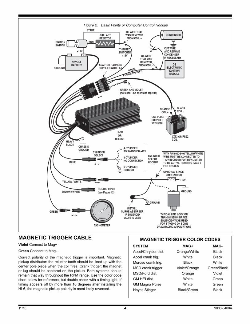
MAGNETIC TRIGGER CABLE VioletConnecttoMag+GreenConnecttoMag-Correct polarity of themagnetic trigger is important.Magneticpickupdistributor:thereluctortoothshouldbelinedupwiththecenterpolepiecewhenthecoilfires.Cranktrigger:themagnetor lugshouldbecenteredonthepickup.BothsystemsshouldremainthatwaythroughouttheRPMrange.Usethecolorcodechartbelowforreference,butdoublecheckwithatiminglight.Iftimingappearsoffbymorethan10degreesafterinstallingtheHI-6,themagneticpickuppolarityismostlikelyreversed.
4
Figure 2. Basic Points or Computer Control Hookup
PS92
MAGNETIC TRIGGER COLOR CODESSYSTEM MAG+ MAG-Accel/Chryslerdist. Orange/White BlackAccelcranktrig. White BlackMorosocranktrig. Black WhiteMSDcranktrigger Violet/Orange Green/BlackMSD/Forddist. Orange VioletGMHEIdist. White GreenGMMagnaPulse White GreenHayesStinger Black/Green Black

11/10 9000-6400A5
1. ConnectHI-6powerandgroundwires.Connect blue cyl-inderselectwireasrequiredforyourengine.Cutmagnetictriggercableshortandtapeupleads.Makesuretheleadsdonotshorttogetherortoground.
2. RemoveOEwire(s)fromCoil+terminal.Tieallthesewirestogether and connect them to the thin red HI-6 switched
LATE MODEL VEHICLES WITH OE ELECTRONIC IGNITION Use thishookup formost latemodelvehicleswithOEelectronicignition.ExceptionsincludeGMvehicleswith4or5pinHEImod-ules(typically1974–1980carsand1974–1985lighttrucksusingadistributorwithvacuumadvance).GMHEIsystemswithvacuumadvance require triggering the HI-6 directly from the magneticpickup.RefertotheMagneticTriggeredSystemssectionfurtheron.
TheHI-6willbetriggeredfromtheoutputof theOEelectronicignitionmodule,usingthewhite“points”triggerinputwire.Beforeproceeding,removeandidentifyallOEwirestotheignitioncoil.Mostapplicationswillrequirecuttingandterminatingthecoilpri-marywires.RefertoFigure2.Hookupisasfollows:
Figure 3. Basic Magnetic Trigger Hookup
PS92
CAUTION: Tape up unused trigger wires. The HI-6 will not fire if the trigger leads are shorted. To prevent misfire, you must route the trigger wires away from the coil wires and spark plug wires. Run them along a frame rail and keep them on opposite sides or far apart as possible.
11/10 9000-6400A6
mustreplacetheGMcoil.WerecommendedthatyouusetheCraneLX92coil.
6. DisconnectOEmodulefrommagnetictrigger.ConnecttheHI-6magnetictriggercabletothedistributorpickuporcranktrigger.Refer to the chart on page 4 forMag+ andMag-colorcodes.GMHEI:refertoFigures4or5foreasyhookupwithinthedistributorusingsuppliedterminals.
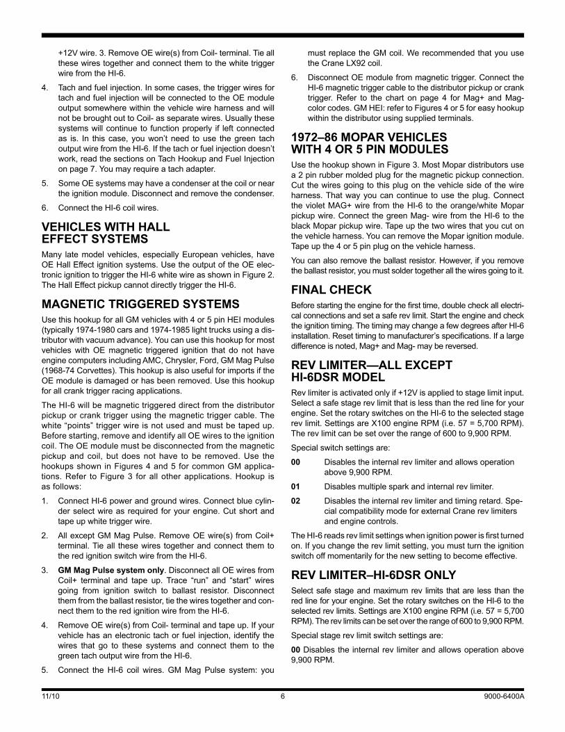
1972–86 MOPAR VEHICLES WITH 4 OR 5 PIN MODULES UsethehookupshowninFigure3.MostMopardistributorsusea2pinrubbermoldedplugforthemagneticpickupconnection.Cutthewiresgoingtothisplugonthevehiclesideofthewireharness.Thatwayyoucancontinue touse theplug.ConnectthevioletMAG+wire fromtheHI-6 to theorange/whiteMoparpickupwire.ConnectthegreenMag-wirefromtheHI-6totheblackMoparpickupwire.Tapeupthetwowiresthatyoucutonthevehicleharness.YoucanremovetheMoparignitionmodule.Tapeupthe4or5pinplugonthevehicleharness.
Youcanalsoremovetheballastresistor.However,ifyouremovetheballastresistor,youmustsoldertogetherallthewiresgoingtoit.
FINAL CHECK Beforestartingtheengineforthefirsttime,doublecheckallelectri-calconnectionsandsetasaferevlimit.Starttheengineandchecktheignitiontiming.ThetimingmaychangeafewdegreesafterHI-6installation.Resettimingtomanufacturer’sspecifications.Ifalargedifferenceisnoted,Mag+andMag-maybereversed.
REV LIMITER—ALL EXCEPT HI-6DSR MODEL Revlimiterisactivatedonlyif+12Visappliedtostagelimitinput.Selectasafestagerevlimitthatislessthantheredlineforyourengine.SettherotaryswitchesontheHI-6totheselectedstagerevlimit.SettingsareX100engineRPM(i.e.57=5,700RPM).Therevlimitcanbesetovertherangeof600to9,900RPM.
Specialswitchsettingsare:
00 Disablestheinternalrevlimiterandallowsoperationabove9,900RPM.
01 Disablesmultiplesparkandinternalrevlimiter.
02 Disablestheinternalrevlimiterandtimingretard.Spe-cialcompatibilitymodeforexternalCranerevlimitersandenginecontrols.
TheHI-6readsrevlimitsettingswhenignitionpowerisfirstturnedon.Ifyouchangetherevlimitsetting,youmustturntheignitionswitchoffmomentarilyforthenewsettingtobecomeeffective.
REV LIMITER–HI-6DSR ONLY Selectsafestageandmaximumrev limits thatare less than theredlineforyourengine.SettherotaryswitchesontheHI-6totheselectedrevlimits.SettingsareX100engineRPM(i.e.57=5,700RPM).Therevlimitscanbesetovertherangeof600to9,900RPM.
Specialstagerevlimitswitchsettingsare:
00 Disablestheinternalrevlimiterandallowsoperationabove9,900RPM.
+12Vwire.3.RemoveOEwire(s)fromCoil-terminal.TieallthesewirestogetherandconnectthemtothewhitetriggerwirefromtheHI-6.
4. Tachandfuelinjection.Insomecases,thetriggerwiresfortachandfuelinjectionwillbeconnectedtotheOEmoduleoutputsomewherewithinthevehiclewireharnessandwillnotbebroughtouttoCoil-asseparatewires.Usuallythesesystemswillcontinueto functionproperly if leftconnectedas is. In this case, youwon’t need touse thegreen tachoutputwirefromtheHI-6.Ifthetachorfuelinjectiondoesn’twork,readthesectionsonTachHookupandFuelInjectiononpage7.Youmayrequireatachadapter.
5. SomeOEsystemsmayhaveacondenseratthecoilorneartheignitionmodule.Disconnectandremovethecondenser.
6. ConnecttheHI-6coilwires.
VEHICLES WITH HALL EFFECT SYSTEMSMany latemodelvehicles,especiallyEuropeanvehicles,haveOEHallEffectignitionsystems.UsetheoutputoftheOEelec-tronicignitiontotriggertheHI-6whitewireasshowninFigure2.TheHallEffectpickupcannotdirectlytriggertheHI-6.
MAGNETIC TRIGGERED SYSTEMS UsethishookupforallGMvehicleswith4or5pinHEImodules(typically1974-1980carsand1974-1985lighttrucksusingadis-tributorwithvacuumadvance).YoucanusethishookupformostvehicleswithOEmagnetic triggered ignition that do not haveenginecomputersincludingAMC,Chrysler,Ford,GMMagPulse(1968-74Corvettes).ThishookupisalsousefulforimportsiftheOEmoduleisdamagedorhasbeenremoved.Usethishookupforallcranktriggerracingapplications.
TheHI-6willbemagnetictriggereddirectfromthedistributorpickuporcranktriggerusingthemagnetictriggercable.Thewhite“points”triggerwireisnotusedandmustbetapedup.Beforestarting,removeandidentifyallOEwirestotheignitioncoil.TheOEmodulemustbedisconnectedfromthemagneticpickupand coil, but doesnot have to be removed.Use thehookupsshowninFigures4and5forcommonGMapplica-tions.Refer toFigure3 forallotherapplications.Hookup isasfollows:
1. ConnectHI-6powerandgroundwires.Connectbluecylin-derselectwireasrequiredforyourengine.Cutshortandtapeupwhitetriggerwire.
2. AllexceptGMMagPulse.RemoveOEwire(s) fromCoil+terminal.Tieall thesewires togetherandconnect themtotheredignitionswitchwirefromtheHI-6.
3. GM Mag Pulse system only.DisconnectallOEwiresfromCoil+ terminal and tape up. Trace “run” and “start” wiresgoing from ignition switch to ballast resistor. Disconnectthemfromtheballastresistor,tiethewirestogetherandcon-nectthemtotheredignitionwirefromtheHI-6.
4. RemoveOEwire(s)fromCoil-terminalandtapeup.Ifyourvehiclehasanelectronictachorfuel injection,identifythewires that go to these systems and connect them to thegreentachoutputwirefromtheHI-6.
5. Connect theHI-6 coil wires.GMMag Pulse system: you
11/10 9000-6400A7
TROUBLESHOOTINGTACH HOOKUPMostfactoryandaftermarkettachswillworkcorrectlywhencon-nectedusingtheinstructionsgiven.Ifyouareaddinganafter-markettachorshiftlight,refertoFigures6and7forhookup.Ifyourtachwillnotwork:
1. Tracetheoriginaltachtriggerwireorrefertoserviceman-ual.IfitwasconnectedtoCoil-,youmustconnectittothegreenHI-6 tach outputwire. If the original tachwirewasconnectedtoCoil+,youwillrequireatachadapter
2. GMvehicleshaveaninlinetachfilter(refertoFigure8).OnvehicleswithHEIcoil-incap,tracethewirefromtheTACH
01Disablesmultiplesparkandinternalrevlimiter.02Disablestheinternalrevlimiterandtimingretard.Specialcom-patibilitymodeforexternalCranerevlimitersandenginecontrols.
TheHI-6readsrevlimitsettingswhenignitionpowerisfirstturnedon.Ifyouchangetherevlimitsetting,youmustturntheignitionswitchoffmomentarilyforthenewsettingtobecomeeffective.
Ifyoudonotrequirethestagelimitfeature,setthedesiredmaxi-mumrevlimit,leavethestagelimitswitchessetto00andleavetheyellow/whitestageinputwiredisconnected.
Figure 4. GM HEI with Coil-In-Cap Hookup Distributorwith Vacuum Advance Mechanism

11/10 9000-6400A8
terminalonthedistributorcap.Allothers,tracewiresfromCoil-.Locatethefilteranddisconnectit.Thenconnectthetachasexplainedinstep1above.
3. If your tach still does not work, you may require a tachadapter.
FUEL INJECTION AND FUEL PUMP RELAYSSome import vehicles are equipped with electronic fuel injec-tionorafuelpumpcut-outrelay.ThesesystemsrequireaRPMsignalthesameasthetach.Iftheenginewillnotstart,firsttryinstallingatachadapterasdescribedintheprevioussection.
Japanese vehicles with fuel injection will require a module
triggerhookupwheretheHI-6whitewireisconnectedtotheoutput of theOEelectronic ignition. Inmost cases, the fuelinjection will not function unless Crane Tach Adapter P/N6000-8910isinstalled.
RUNNING ON Runningonisaconditionwheretheenginecontinuestorunaftertheignitionswitchisturnedoff.First,verifythattheconditionisduetotheignitionsystem.Dieselingcancauserunningon.Theenginewillrunveryroughwhenitisdieseling.Thismaybeduetoanoverlyrichmixture,excessivetiming,orheavycarbondeposits.Dieselingcanusuallybecuredbyinstallingcoldersparkplugs.
Figure 5. GM HEI with External Coil Hookup Distributorwith Vacuum Advance Mechanism
OR PS92

11/10 9000-6400A9
With ignition runon, theenginecontinues to runsmoothly,asiftheignitionhadnotbeenturnedoff.IgnitionrunoniscausedfromcurrentleakingbacktotheHI-6throughthechargingsys-temindicator.Tosolvethisproblem,installadiodeonthevoltageregulator.
GM vehicles with Delcotron alternator and internal regulator:refertoFigure9.Installadiodeinthethinbrownwiregoingtotheindicatorlight.
GMorFordwithexternalvoltageregulator: refer toFigure10.ForGMvehicles, install a diode on the #4 terminal. For Fordvehicles,installadiodeontheterminalmarked“I”.
InstallationofadiodemaynotcorrecttherunonproblemonsomeAMCvehicles.Refer toFigure11.Usea1973–76Chryslerdualballastresistor(availableatmostpartsstores).Solderajumperwireacrossbothterminalsononeend.ThenconnecttheterminalsontheotherendtogroundandtotheredignitionswitchwirefromtheHI-6.
RADIO NOISE Apowerfulmultiplesparksystemsuchas theHI-6will tend togeneratemorenoisethantheOEignition.Tosomeextentthisisunavoidable,butstepscanbetakentoreducethenoiselevel.
Radiofrequency(RF)noiseisradiatedfromcoilandsparkplugwires.RFnoiseprimarilyaffectsAMandCBradios.Conductednoise appears as a whine that follows engine RPM andmayaffectallsystemsincludingtapeplayersandFMradio.UsethefollowingchecklisttoreduceRFnoise:
1. Makesureagroundstrap is installedbetweentheengineandchassis.
2. Makesurethatradio, tapeandCBsystemsaregroundeddirecttothechassis.
3. MounttheHI-6unitasfarawayaspossiblefromtheantenna(includingwindshieldantenna)andotherelectronicdevices.MakesuretheHI-6isgroundeddirecttothechassis.Keepthegroundwireshort,preferablynomorethan6”.
4. Replacesparkplugwireswithspiralcoretypewire.Replacerotor and cap.Apply a small amount of silicone dielectricgreasetotherotortipandtoallhighvoltageterminals.Useonlyresistorsparkplugswhenrunningonthestreet.
ConductednoisefromtheHI-6iscarriedthrough+12voltpowerconnections.Conductednoisecanbereducedbyinstallingapowerlinenoisefilter(availableatRadioShack)neartheaffectedradio.
NOISE SUPPRESSION ON STAGE LIMIT INPUTInsomeapplicationsthestageinput(yellow/whitewire)iscon-nectedtoaswitchthatalsocontrolsalinelockortransmissionbrakesolenoidvalve.Whentheswitchopensandcurrentflowtothesolenoidisinterrupted,electricaltransients(upto500volts)occur.These transients can lead to glitches in on-board elec-tronics.Arcingalsooccursinswitchcontactsgreatlydecreasingswitch lifeandpossiblyresulting inerraticoperation.Thismaycauseinconsistentlaunchand60foottimes.
Thesolutionistoinstallasurgeabsorber.Itwilllimitthemaxi-mumvoltagetoabout40volts.Thesurgeabsorberappearsasasmall1/2inchdiameterdiskwithtwowireleads.SolderoneleadtothestageswitchandtheotherleadtoaterminalthatconnectstogroundasshowninFigures2or3.
POWER SUPPLY FILTER CAPACITOR HOOKUP Afiltercapacitoronthe12voltsupplyisrecommendediftheHI-6powerwiresareextended,thebatteryislocatedinthetrunk,orsolenoid valvesdrawingmore than10ampsareused.Useaminimum38,000microfarad(uF)16voltcapacitorsuchasCraneP/N9000-0014. Install thecapacitoracross the12volt supply(heavyredwire)andchassisgroundneartheHI-6unit.
TROUBLESHOOTING HI-6 OPERATION DidtheenginerunproperlybeforeinstallationoftheHI-6?Ifnot,removetheHI-6,reinstalltheOEignitionoranotherknowngoodunitandthenfindandcorrecttheoriginalproblem.DidtheHI-6functioncorrectlybeforetheproblemoccurred?Iftheansweris
Figure 6. Shift Light Hookup
Figure 7. Aftermarket Tach Hookup
Figure 8. GM Tach Filters

11/10 9000-6400A10
3. Routeallmagnetictriggerconnectionsawayfromanyotherwiring,especiallyHI-6coilcableandanyhighvoltagecoilandsparkplugwires.
4. Replace spark plugs. Check that spark plugs are propertype,heatrange,andgapsize.
5. Replacedistributorhighvoltagerotorandcap.
6. Replacesparkplugwires.Donotusesolid corewiresorhighresistancewires.Useonlyspiralcoretypewires.
7. Checkforlooseorcorrodedconnectionsandbrokenwiresatmagneticpickup,HI-6unit,coil,anddistributorcap.Alsocheck distributor for loose, missing, or jamming parts inpickuporadvancemechanism(ifused).Magneticpickupsandcranktrigger:checkforproperairgap.
yes,didyouchangeanythingthatmayhaveaffectedit?Ifyouconnectedanexternalcontrolorchangedignitioncoils,trygoingbacktothelastsetupthatworkedOKtohelpisolatetheproblem.
Iftheenginewillnotstart,orrunsroughorintermittently,usethefollowingcheckliststeps:
INTERNAL DIAGNOSTICS When the ignition switch is turned on, theHI-6 completes aninternal diagnostic check and lights up the status LED.Whentheengineiscranked,thestatusLEDwillrapidlyblinktoindicatethatavalidtriggersignalisbeingreceived.
NO STATUS LED WHEN IGNITION IS ON IfthestatusLEDdoesn’tlightupaftertheignitionswitchisturnedon,checkpowerandgroundconnections.Useavoltmeter toverify+12voltsat the twoHI-6redwires.Makesureyoualsohave+12voltswhentheignitionswitchisinstartposition.TheHI-6requiresaminimumvoltageofabout+9.5voltswhentheignitionswitch is first turnedon.Duringcranking, theHI-6willcontinuetooperatedowntoabout+7volts.
ENGINE WILL NOT START 1. IfthestatusLEDlightsupwhentheignitionswitchisturned
onbut theenginewillnotstart,verify that thestatusLEDblinkswhiletheengineiscranking.
2. If thestatusLEDdoesn’tblink, theHI-6 isnot receivingatriggersignal.Rechecktriggersignalelectricalconnectionsand trigger source.Make sure themagnetic trigger leadsarenotshortedtogetherortoground.Makesurethewhitepointstriggerwireisnotshortedtoground.
3. IfthestatusLEDblinks,butenginewillnotstart,recheckcoilprimaryconnectionsorreplacecoil.TheonlywiresgoingtothecoilprimaryshouldbetheorangeandblackwiresfromHI-6coilcable.Note:GMinternalHEIcoilsrequireagroundwirethatgroundsthesecondaryandcoretothedistributor.
4. Iftheenginemomentarilystartsandthendies,gobacktotheFuelInjectionAndFuelPumpRelaysectiononpage8.
CHECKING FOR SPARK Tocranktheenginewithoutstartingortocheckforspark,useaKDToolsHEItestplug.Thetestplugcomeswithanalligatorclipthatcanbeattachedtochassisground.Makeupalengthofsparkplugwiretoconnectthetestplugtothecoil.
MISFIRE OR INTERMITTENT OPERATION 1. Aweakbatterymaycausemisfireorintermittentoperation,
especiallyathighRPM,ifbatteryvoltagedropsbelow+10volts.Ifindoubt,chargeorreplacethebattery.
2. FieldexperiencehasshownthatmisfireathighRPMisusu-ally not an electrical problemwithin theHI-6.Coil failure,includinginternalarcingorarcingatthehighvoltagetermi-nal,isacommoncause.Arcingacrosssparkplugbootsorthedistributorcapisalsocommon.
10
Figure 9. Diode Installation on Delcotron Alternator
Figure 10. Diode Installation on External Regulator
Figure 11. Run-On Fix Using Chrysler Ballast Resistor
WARNING: High voltage is present at the coil primary and secondary Terminals. Do not touch the coil while the engine is running. Do not connect any test equipment to any coil terminal.

11/10 9000-6400A11
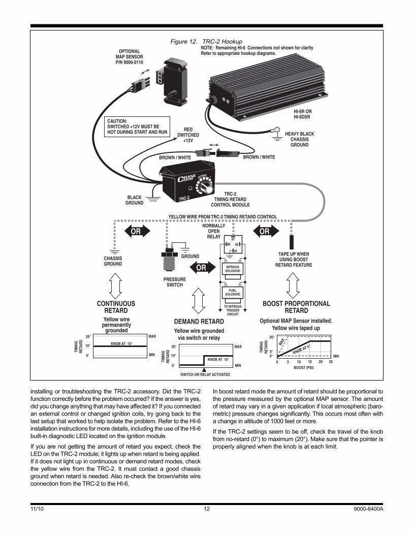
TRC-2 TIMING RETARD CONTROL INSTALLATION AND OPERATION TheCraneCamsTRC-2isanaccessoryforHI-6systemsthatprovidesdriver-adjustableretard.TheTRC-2canprovidecon-tinuoustimingretard(0°–20°),retardusingaswitch(0°–20°),orretardproportionaltoboost(upto4°perpsi)onsuperchargerortur-bochargerinstallations(withanoptionalMAPsensor,notincluded).
INSTALLATIONComplete the installation of the HI-6 ignition module prior toinstallingtheTRC-2.Figure12showshookupof theTRC-2totheHI-6.The redwire from theTRC-2 is connected to a keyswitched+12voltsupply.YoumayspliceitintothethinredwireontheHI-6.TheyellowwirefromtheTRC-2isconnecteddirectlytogroundforcontinuousretardcontrol,throughaboost/nitrousswitchtogroundforretardondemand,ortapedoffwhenusingthe optionalMAP sensor.When using retard on demand, theswitchmustcompletethecircuittogroundtoactivatetheretard(useanormallyopenswitchorrelay).
FINAL CHECK Beforestartingtheengineforthefirsttime,doublecheckallelec-tricalconnections.SettheTRC-2knobto0°(fullycounterclock-wise), thenstart theengineandcheck the ignition timing.Thetimingmaychangeafewdegreesafterinstallation.Resettimingtomanufacturer’sspecs.Uponstartingtheengine,theLEDontheTRC-2modulewillbelitonlyiftheyellowwireisgrounded.
OPERATION TheTRC-2moduleallowsyoutoadjusttheamountofretardpro-ducedbytheHI-6.ItalsocontainsanLEDthatindicateswhentheretardfunctionisactivated.HowyouusetheTRC-2dependsonwhetheryouhaveconnected it forcontinuous,demand,orboost-proportionalretard.
CONTINUOUS RETARD Refer to Figure 12. Connect the yellow wire from the TRC-2directlytochassisgroundforcontinuousretard.Sincetheretardfeatureisactiveallthetime,theLEDontheTRC-2willbeillu-minatedwheneverthekeyison.Turningtheknobfullycounter-clockwise(0°)producesnoretard.Turning theknobclockwiseincreasestheretardupto20°.TheTRC-2isapproximatelylinearthroughoutitsrange,sohalfscaleisabout10°ofretard.Forpre-ciseretardcalibration,youmustuseahigh-qualitytiminglight.
Theusesforthistypeoftimingcontrolincludeadjustingtimingtoprevent knockbecauseof inferior fuel qualityor insufficientoctane,altitudeadjustments, etc.Asyoudrive, youcanapplyjust theamountof retard required topreventsparkknockandoptimize fuel economy. In racing applications the retard con-trolcanbeusedtotunethevehicletospecifictrackandatmo-spheric conditions.TheTRC-2 alsomay be used on vehicleswithmechanicaladvancedistributororcomputerenginecontrolstochangethetotalignitiontiming.
DEMAND RETARD RefertoFigure12.ConnecttheyellowwirefromtheTRC-2toanormallyopenswitchorrelaythatwillcompleteapathtochassisgroundwhenretardisdesired.WARNING:Highvoltageispres-
entatthecoilprimaryandsecondaryTerminals.Donottouchthecoilwhiletheengineisrunning.Donotconnectanytestequip-menttoanycoilterminal.
Example:Apressureswitchthatclosesatacertainboostlevel.The LED on the TRC-2 will light up when the yellow wire isgrounded.WhentheLEDislit,theretardfeatureisactiveandthesparkisretardedbytheamountsetontheTRC-2knobfrom0°-20°.TheTRC-2isapproximatelylinearthroughoutitsrange,sohalfscaleisabut10°ofretard.Forpreciseretardcalibration,youmustuseahigh-qualitytiminglight.ThediagraminFigure12showsanexamplewiththeknobsetfor10°ofretard.
Thistypeoftimingcontrolisgreatfornitrousoxideandsuper-charged applications, or any vehicle that requires adjust-ableretard.Fornitrousapplications,Figure12showshowanormally-open relay isused toground theyellowwirewhennitrous and fuel solenoids are activated. The pin numbersareforastandardautomotiverelaysuchasRadioShackP/N275-226. Figure 12 also shows a pressure activated switchdesignedtoretardtimingwhentheboostpressurereachesapre-setvalue.NAPABalkampofferstwoadjustablepressureswitches:P/N701-1591 (3-7psig range)andP/N701-1603(1.1-3psigrange).
Demand retard mode is also great for crank trigger systemswhereamomentarystartretardisrequired.Amanualswitchoranormallyopenrelayenergizedbythestartersolenoidcanbeusedtogroundtheyellowwireduringcrankingtoprovideupto20°ofstartingretard.Oncetheswitchisreleased,timingreturnstonormal.
BOOST PROPORTIONAL RETARD RefertoFigure12.AnoptionalMAPsensor(CraneP/N9000-0110) is required for boost proportional retard. This sensor isa ruggedunit thatcanmeasurepressuresup to15psiabovenormalatmosphericpressure.Thesensorcomeswithvacuumtubingandadaptersforplumbingittotheintakemanifold.TheyellowwirefromtheTRC-2shouldbetapedupwhenusingtheMAPsensor.
When theMAPsensor isconnected, the retardsettingon theTRC-2nowreferstoaretardslopefrom0°to4°perpsiofboost.Simplydividetheknobsettingby5todeterminetheretardslope(seeFigure12).Forexample,iftheknobissetto5°theretardslopeis1°perpsiandat5psiofboosttheretardis5°.Asboostrises further, the retard increases at this same slope up to amaximumof20°.Iftheboostlevelexceeds15psi,theretardlev-elsoffasshowninFigure12below(sensordamagemayoccurabove18psi).
ThestatusLEDontheTRC-2illuminateswhenretardisbeingapplied.Undermostconditions,thisoccursbetween0.5and1.0psiofboost.Asboostrises,retardriseswithaslopedeterminedbytheknobsetting.Notethattheretardslopestopsrisingwhentheboostreaches15psiortheretardreaches20°.TheTRC-2isapproximatelylinearthroughoutitsrange,butforpreciseretardcalibrationuseatiminglighttoobtainretardvalue.
TROUBLESHOOTING DidtheenginerunproperlybeforeinstallationoftheTRC-2?Ifnot,removetheboth theTRC-2andHI-6units, reinstall theOE igni-tionoranotherknowngoodunitandthenfindandcorrecttheorigi-nalproblem.MakesuretheHI-6systemfunctionsproperlybefore
11/10 9000-6400A12
InboostretardmodetheamountofretardshouldbeproportionaltothepressuremeasuredbytheoptionalMAPsensor.Theamountofretardmayvaryinagivenapplicationiflocalatmospheric(baro-metric)pressurechangessignificantly.Thisoccursmostoftenwithachangeinaltitudeof1000feetormore.
IftheTRC-2settingsseemtobeoff,checkthetraveloftheknobfromno-retard(0°)tomaximum(20°).Makesurethatthepointerisproperlyalignedwhentheknobisateachlimit.
installingortroubleshootingtheTRC-2accessory.DidtheTRC-2functioncorrectlybeforetheproblemoccurred?Iftheanswerisyes,didyouchangeanythingthatmayhaveaffectedit?Ifyouconnectedanexternalcontrolorchangedignitioncoils,trygoingbacktothelastsetupthatworkedtohelpisolatetheproblem.RefertotheHI-6installationinstructionsformoredetails,includingtheuseoftheHI-6built-indiagnosticLEDlocatedontheignitionmodule.
Ifyouarenotgettingtheamountofretardyouexpect,checktheLEDontheTRC-2module;itlightsupwhenretardisbeingapplied.Ifitdoesnotlightupincontinuousordemandretardmodes,checkthe yellowwire from theTRC-2. Itmust contact a good chassisgroundwhenretardisneeded.Alsore-checkthebrown/whitewireconnectionfromtheTRC-2totheHI-6.
Figure 12. TRC-2 Hookup