crane xr-700 installation tips cd - sl113.org · in a typical kettering ignition system, the...
TRANSCRIPT

Crane XR-700 Optically-Triggered Ignition System
Installation Instructions and Tips
Prepared by:
John Hassell 2210 Cardigan Hill
San Antonio, Texas 78232 Tel: 210 497 8830 Fax: 210 497 8844 Mob: 210 421 4679
Email: [email protected]
Date: 21 January 2002 Revised: 15 April 2002

2
Table of Contents
Section Title/Description Page 1.0 INTRODUCTION 4 1.1 Ignition System Basics 4 1.1.1 How it Works 5 1.1.2 Other Causes for Point Failure 8 1.2 Solving the Points Problem 8 1.2.1 How the Transistorized System Works 11 1.3 Function of the Crane Ignition System 12 1.4 Summary 13 2.0 INSTALLATION INSTRUCTIONS AND TIPS 14 2.1 Installation Options 14 2.2 Equipment, Tools and Materials Required 15 2.3 System Components 16 2.4 Procedure 16 2.5 Additional Procedures 25 3.0 OPTIONAL INSTALLATION INSTRUCTIONS 26 3.1 Manufacturing the Mounting Plate 26 3.2 Assembling the Mounting Plate and Spacers 26 3.3 Marking, Drilling and Tapping the Mounting Holes 27 3.4 Installing the Mounting Plate 27 3.5 Installing the Crane Ignition Module 29
List of Figures Figure Title Page 1-1 Standard Kettering Ignition System for a 1969 280SL 4 1-2 Dwell Set to Proper Value 7 1-3 Point Gap too Wide – Higher Dwell Angle 8 1-4 Point Gap too Narrow – Lower Dwell Angle 8 1-5 Mercedes Benz transistorized Ignition Wiring (Typical 113 9
Chassis) 1-6 Mercedes Benz Transistorized Ignition – Internal Layout of 10 Module 1-7 Shutter Trigger Assembly 12 1-8 Shutter Closed 13 1-9 Shutter Open 13 2-1 Crane XR-700 in Author’s 280SL – Above Sub-Frame 14 Mount 2-2 Line Drawn on Distributor Housing 16 2-3 Alignment of Rotor with Drawn Line 17 2-4 Point Cable Connection for MB Transistorized Ignition 18 2-5 Pin Connections for Molex Connectors 20 2-6 Set-up for Optical Trigger Alignment 21 2-7 Firing Order Distributor Top View 22

3
List of Figures, Continued Figure Title Page 2-8 Wiring for Vehicles Without Mercedes Benz Transistorized 22 Ignition 2-9 Wiring for Vehicles With Mercedes Benz Transistorized Ignition 23 2-10 Crane Ignition System Wiring – 280SL 24 3-1 Ignition Module Mounting Plate 26 3-2 Location for Mounting Plate Above Sub-Frame Mount 27 3-3 Placing Screws Into the Spacers 28 3-4 Module Mounting Screws Detail 28 3-5 Mounting Plate Installed 29 3-6 Crane Ignition Module Installed 29
List of Tables Table Title Page 1-1 Mercedes Benz Terminal Numbering Convention 10 2-1 Components Required 15 2-2 Test Equipment and Tools Required 15 2-3 Hardware and Materials Required 15 2-4 Optional Hardware, Tools and Materials 15

4
1.0 INTRODUCTION NOTE: Proper installation, testing and adjustment of this device require succinct knowledge of ignition systems as well as standard ignition test equipment. Only qualified personnel should attempt it. This document describes installation and testing of the Crane XR-700 Optically-triggered Ignition System into a 1969 Mercedes Benz 280SL. It is not meant to replace the installation instructions that come with the ignition system, but rather to supplement those instructions with first-hand experience. 1.1 Ignition System Basics A man named Kettering developed the fundamental ignition system more than 70 years ago. Even today, the simple system consisting of battery, coil, points and condenser is referred to as the Kettering system. Figure 1-1 depicts the standard system as installed in a Mercedes Benz, 1969 280SL (113 chassis). The terminal numbers are those shown on Mercedes Benz wiring diagrams for the 113 Chassis.
Figure 1-1: Standard “Kettering” Ignition System for a 1969 280SL
30
- + 50
ChassisGround 30 Off
5015 R
Condenser
415 1
IgnitionCoil
0.6 Ohm
Start
On/Run
Battery
BallastResistor
StarterMotor
To RadioRadio
Distributor
Points
Ignition Switch

5
1.1.1 How it Works When the ignition switch is turned to the ON/RUN position, terminals 30 and 15 are connected. This connects 12 volts from the battery to terminal 15 (input side) of the ballast resistor. The other side of the ballast resistor is connected to the positive (+) terminal of the ignition coil. The negative (-) terminal of the ignition coil is connected to the points inside the distributor. If the points happen to be open, no current flows through the coil and no spark occurs. If the points are closed, current flows from the battery, through the ballast resistor, through the primary winding of the coil, through the points to ground, thus completing the ignition circuit. When the ignition switch is turned to the START position, several things happen. The starter motor is engaged via 12 volts from the battery applied to the starter solenoid/switch from terminal 50 of the ignition switch. The solenoid pulls in or closes and current is supplied to the starter motor, which begins cranking the engine. Simultaneously, 12 volts is applied directly to the positive (+) terminal of the ignition coil via terminal 50 of the ignition switch. This effectively shorts or bypasses the ballast resistor. Thus, in the START position, the engine is cranking and full battery voltage is applied to the ignition coil. As the engine begins to turn, so does the center shaft in the distributor. This causes the points to begin to open and close. When the points are closed, a high current flows through the primary winding of the ignition coil to ground. The condenser is also shorted or bypassed when the points are closed. When the points open, the magnetic field of the coil primary collapses and a high voltage is induced in the coil’s secondary winding, which results in a high voltage (15,000 – 25,000 volts) to be routed to a spark plug via the distributor rotor. The spark fires the fuel/air mixture in the cylinder and the engine starts to run. The condenser serves two purposes. First, it reduces arcing between the points and second, it slightly increases the energy in the spark. It’s primary function, however, it to increase point life by reducing arcing. When the ignition switch is released to the ON/RUN position, the bypass across the ballast resistor is removed and power to the positive terminal of the ignition coil is supplied through the ballast resistor. At this point, the voltage applied to the positive terminal of the ignition coil is less than full battery voltage. This reduces the current through the points and extends their operational life, however, it also reduces the amount of high voltage available for spark.

6
As can be discerned from the above discussion, the points are the weak link in the system for two reasons, namely:
1. Mechanical wear caused by the open/close action created by the distributor camshaft. In actuality, the fiber pawl on the points wears out. Usually, however, the points will require replacement before this happens.
2. Burning and pitting caused by switching high coil current. This is the main
reason for point failure. To examine why this happens, let’s review a bit of simple Ohm’s law. The current flowing through any circuit is a function of voltage and resistance. The basic relationship is: I = E/R Where: I = Current in Amperes E = Voltage in Volts R = Resistance in Ohms In a typical Kettering ignition system, the resistance of the primary winding of the ignition coil is about 0.4 ohms. This is also the primary resistance of the standard “blue” Bosch ignition coil used in most 113 chassis cars. Normally, when an engine is running, the battery voltage will be about 13.2 volts (due to the charging action of the alternator). So, if the battery exhibits 13.2 volts and the coil has a resistance of 0.4 ohms, the current through the points is… I = 13.2/0.4 = 33 Amperes. That’s a LOT of current. In reality, we must also add the resistance of the wires to/from the battery and ignition switch to the calculation. We can assume that the total resistance of the wires and switch will be about 0.5 ohms. Therefore, the total resistance of the coil and the wiring will be about 0.9 Ohms. This gives us… I = 13.2/0.9 = 14.6 Amperes or less than half what we calculated above. But, when the ignition switch is released to the ON/RUN position, the ballast resistor is now placed in the circuit. The ballast resistor usually has a resistance of about 0.6 Ohms. This makes the total resistance of the circuit – coil primary + wiring + ballast resistor (0.4 + 0.5 + 0.6) equal to 1.5 Ohms. If we put this into the calculation we have… I = 1.32/1.5 = 8.8 Amperes Now, we must also include the fact that the points are not ALWAYS closed, they open and close rapidly as the engine runs. Thus, the amount of AVERAGE current flowing the
7
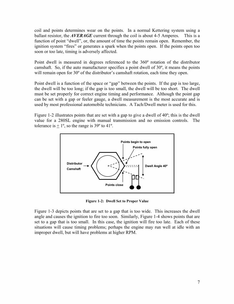
coil and points determines wear on the points. In a normal Kettering system using a ballast resistor, the AVERAGE current through the coil is about 4-5 Amperes. This is a function of point “dwell”, or, the amount of time the points remain open. Remember, the ignition system “fires” or generates a spark when the points open. If the points open too soon or too late, timing is adversely affected. Point dwell is measured in degrees referenced to the 360º rotation of the distributor camshaft. So, if the auto manufacturer specifies a point dwell of 30º, it means the points will remain open for 30º of the distributor’s camshaft rotation, each time they open. Point dwell is a function of the space or “gap” between the points. If the gap is too large, the dwell will be too long; if the gap is too small, the dwell will be too short. The dwell must be set properly for correct engine timing and performance. Although the point gap can be set with a gap or feeler gauge, a dwell measurement is the most accurate and is used by most professional automobile technicians. A Tach/Dwell meter is used for this. Figure 1-2 illustrates points that are set with a gap to give a dwell of 40º; this is the dwell value for a 280SL engine with manual transmission and no emission controls. The tolerance is + 1º, so the range is 39º to 41º.
Figure 1-2: Dwell Set to Proper Value
Figure 1-3 depicts points that are set to a gap that is too wide. This increases the dwell angle and causes the ignition to fire too soon. Similarly, Figure 1-4 shows points that are set to a gap that is too small. In this case, the ignition will fire too late. Each of these situations will cause timing problems; perhaps the engine may run well at idle with an improper dwell, but will have problems at higher RPM.
Points begin to openPoints fully open
DistributorCamshaft
Dwell Angle 40º
Points close

8
Figure 1-3: Point Gap too Wide – Higher Dwell Angle
Figure 1-4: Point Gap too Narrow – Lower Dwell Angle
1.1.2 Other Cause for Point Failure When the ignition switch turned to the ON/RUN position (before the car started or to listen to the radio) it is possible that the points in the distributor are closed. Thus, we would have about 8 Amperes of current being drained from the battery and the points would begin to heat from the current. In order to avoid this, a “radio” or “accessory” position was added to the ignition switch of most vehicles. In the radio position, no power is applied to the ignition system, battery drain is significantly lowered and the points do not wear due to heat. 1.2 Solving the Points Problem The most common ignition failures are points and spark plugs, followed closely by the distributor rotor, cap and spark plug wires. The points, however, are the “Achilles Heel” of the system. If we could find a way to extend the life of the points, there would be fewer failures and tune-ups. Automobile manufacturers began to employ transistorized ignition systems in the late 1960s and early 1970s to eliminate or reduce point failure. Figure 1-5 shows a typical transistorized ignition system as used with the 113 Chassis, specifically the 1969 280SL.
Points begin to openPoints fully open
DistributorCamshaft
Dwell Angle 50º
Points close
Points begin to openPoints fully open
DistributorCamshaft
Dwell Angle 30º
Points close

9
Figure 1-5: Mercedes Benz Transistorized Ignition Wiring (Typical 113 Chassis)
This system significantly reduces point current by using a high power transistor – located inside the module – to handle the current through the ignition coil; the points simply trigger the transistor. Figure 1-6, on the next page, shows the internal layout of the ignition module. The following text explains how the module works and how the current through the points is reduced.
30
Starter Motor
- + 1650
ChassisGround 30 Off
5015 R
Condenser
415 1
IgnitionCoil3
Battery
Start
15 16 7
To RadioOn/Run Radio
0.6 Ohms
Ignition DistributorSwitch
Points
TransistorizedIgnition Module
Ballast Resistor0.4 Ohms
Ballast Resistor

10
Figure 1-6: Mercedes Benz (Bosch) Transistorized Ignition – Internal Layout of Module
In order to better understand how the system functions, one needs to understand the Mercedes Benz numbering convention used in their diagrams. The numbers used to identify the terminals on switches, modules and other components follow a specific convention to tell the reader what voltage or signal is found on the terminal. The standard convention is shown below in Table 1-1.
Table 1-1: Mercedes Benz Terminal Numbering Convention
1.2.1 How the Transistorized System Works When the ignition switch is set to the ON/RUN position, +12 Volts is applied to terminal 15 of the ignition module through the 0.4 Ohm ballast resistor. When the ignition switch is set to the START position (engine cranking) +12 volts is applied directly to terminal 15 of the ignition module from the solenoid on the starter motor. This effectively bypasses the 0.4 ohm ballast resistor and offers higher voltage during cranking.
C2
BallastResistor Q1 15 10.4 Ohm 16
15D1
On15 50
Off R1Start
Ignition 30 C1Switch R2
3 7Condenser
To StarterTerminal 16
+12V Battery
Distributor
IngitionCoil
Points
Transistorized Ignition Module
Ballast Resistor0.6 Ohm
+12 Volts when the ignition switch is in the RADIO or ON/RUN position+12 Volts when the ignition switch is in the START position+12 Volts direct from the battery, not switched+12 Volts when the engine is cranking (from starter motor)16
3050R
Terminal Number Definition
115 +12 Volts switched (ON/RUN position of the ignition switch)
Ignition coil negative (-) termnial

11
When the engine starts and the ignition switch is returned to the ON/RUN position, +12 Volts is again supplied to terminal 15 of the ignition module through the 0.4 Ohm ballast resistor. A typical firing sequence is as follows.
1. +12 Volts is applied to the ignition module through the 0.4 Ohm ballast resistor
2. Assuming that the points in the distributor are open, transistor Q1 is turned off
because terminal 7 of the ignition module is open (no ground from the points). No voltage is present at terminal 16 of the ignition module, thus no current flows through the 0.6 Ohm ballast resistor or the ignition coil.
3. As the engine cranks, the hexagonal cam in the distributor begins to turn and
the points close.
4. When the points close, a ground is applied to terminal 7 of the ignition module and transistor Q1 turns on. This applies +12 Volts to terminal 15 of the ignition coil through the 0.6 Ohm ballast resistor.
The current through the points is extremely small (thousandths of an Ampere or milli-amperes) instead of 4-5 Amperes as seen in a non-transistorized system.
5. When transistor Q1 is turned ON, capacitor C2 is discharged (shorted by Q1).
6. When the points open, capacitor C2 begins to charge. The charge path is: +12
Volts from the ignition switch – 0.4 Ohm ballast resistor – C2 – 0.6 Ohm ballast resistor and the ignition coil to ground.
7. As capacitor C2 begins to charge, a pulse is created in the ignition coil, which
causes a high voltage to be generated and sent to the appropriate spark plug.
8. When the points close again, transistor Q1 is turned ON and the cycle repeats. Point wear and stress is significantly reduced since the transistor is handling the current through the coil (4-5 Amperes). The points were designed to switch high currents repeatedly for tens-of-thousands of miles, therefore, when switching a very small current, they should last for a much longer time. Tune-up intervals (due to point failure) become longer and vehicle maintenance becomes cheaper. But (yes, there’s always a “but”), we STILL have the points. Points are mechanical, subject to bounce and vibration and must be actuated – mechanically – by the camshaft in the distributor. Whereas the wear on the point contacts has been reduced, the fiber pawl, which rides between the points and the distributor camshaft, can still wear out or break.
12
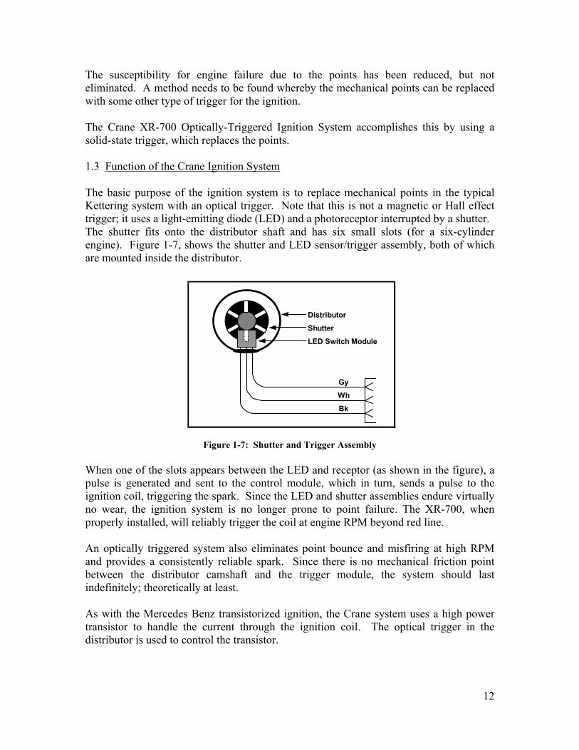
The susceptibility for engine failure due to the points has been reduced, but not eliminated. A method needs to be found whereby the mechanical points can be replaced with some other type of trigger for the ignition. The Crane XR-700 Optically-Triggered Ignition System accomplishes this by using a solid-state trigger, which replaces the points. 1.3 Function of the Crane Ignition System The basic purpose of the ignition system is to replace mechanical points in the typical Kettering system with an optical trigger. Note that this is not a magnetic or Hall effect trigger; it uses a light-emitting diode (LED) and a photoreceptor interrupted by a shutter. The shutter fits onto the distributor shaft and has six small slots (for a six-cylinder engine). Figure 1-7, shows the shutter and LED sensor/trigger assembly, both of which are mounted inside the distributor.
Figure 1-7: Shutter and Trigger Assembly
When one of the slots appears between the LED and receptor (as shown in the figure), a pulse is generated and sent to the control module, which in turn, sends a pulse to the ignition coil, triggering the spark. Since the LED and shutter assemblies endure virtually no wear, the ignition system is no longer prone to point failure. The XR-700, when properly installed, will reliably trigger the coil at engine RPM beyond red line. An optically triggered system also eliminates point bounce and misfiring at high RPM and provides a consistently reliable spark. Since there is no mechanical friction point between the distributor camshaft and the trigger module, the system should last indefinitely; theoretically at least. As with the Mercedes Benz transistorized ignition, the Crane system uses a high power transistor to handle the current through the ignition coil. The optical trigger in the distributor is used to control the transistor.
DistributorShutterLED Switch Module
GyWhBk

13
Figure 1-8 shows the trigger module in the distributor with the shutter closed, that is to say, the optical path between the LED and the photoreceptor is blocked. In this mode, the output to the ignition module is 0 volts.
Figure 1-8: Shutter Closed
Figure 1-9 shows the trigger module with the shutter open. There is now a clear optical path between the LED and the photoreceptor and the receptor turns ON. At this point, the output to the ignition module is 12 Volts.
Figure 1-9: Shutter Open
As the shutter rotates on the distributor shaft, the action continues for each cylinder causing the ignition module to initiate the spark through the ignition coil. The points have now been eliminated completely and replaced by a solid-state trigger module that receives virtually no mechanical wear. The “Achilles Heel” of the system is gone; engine reliability is significantly increased. 1.4 Summary
1. Points are the weakest link in a conventional, Kettering ignition system. 2. Transistorized ignition systems improve point life by reducing current 3. Optically triggered systems eliminate points and increase reliability 4. Transistorized and optically triggered systems do not necessarily improve
engine performance or create a hotter spark 5. Optically triggered systems provide a consistent spark at all RPM
Shutter Closed
LED
Photo-Receptor
Output = 0 Volts
+12 V
Ground
Output
Shutter Open
LED
Photo-Receptor
Output = 12 Volts
+12 V
Ground
Output

14
2.0 INSTALLATION INSTRUCTIONS AND TIPS The procedures described herein are intended to supplement the installation instructions that accompany the Crane system. The tips and advice offered are based on actual installation of this system into a 1969 280SL. Generally, the process follows the Crane instructions. 2.1 Installation Options The tools and materials required for installation depend upon where the control module is mounted in the engine compartment. A clear, flat space approximately 3-1/2” square is needed for the module. DO NOT mount the control module to the engine. Possible locations are the firewall, fender, etc. Any location will suffice as long as air can flow over the module to cool the internal power transistor. If your 280SL uses the Mercedes Benz transistorized ignition module, you can remove the module and replace it with the Crane module. The Mercedes Benz module is mounted under the battery rack and can be accessed only from under the vehicle, or with the battery and battery shelf removed. The author elected to mount the Crane module above the left-front sub-frame mount on the driver’s side fender well, as shown in Figure 2-1.
Figure 2-1: Crane XR-700 in Author’s 280SL – Above Sub-Frame Mount

15
2.2 Equipment, Tools and Materials Required If you elect to mount the control module in a manner different from the author’s, please refer to tables 2-1, 2-2 and 2-3 for components, test equipment, tools, hardware and materials. If you wish to mount the module in the same manner as the author, please refer to the additional items required as listed in Table 2-3.
Table 2-1: Components Required
Figure 2-2: Test Equipment and Tools Required
Table 2-3: Hardware and Materials Required
Table 2-4: Optional Hardware, Tools and Materials
REF Description Quantity1 Crane XR-700 Ignition System 12 Ballast resistor, Bosch 0227 901 013 1
Components
Ref Description Quantity1 Multimeter, DC, analog or digital 12 Timing light 13 External electronic tachometer 14 5mm hex key, 1/4" drive, with integral universal joint 15 1/4" drive T-handle 16 Screwdriver, flat-tip, stubby 17 Screwdriver, #2 Phillips, stubby 18 Nut driver (or open/box end wrench), 8mm (coil terminals) 19 Nut driver (or box-end wrench), 7mm (ballast resistor terminals) 110 Electric drill, 1/4" chuck minimuim 111 Drill bit, 9/64" 112 Terminal crimping tool/bolt cutter, standard 1
Test Equipment and Tools
Ref Description Quantity1 Rubber grommet, 3/8" ID, 1/2" OD 12 RTV self-vulcanizing rubber, any color Tube3 Round terminal lug, crimp, #10 stud, AWG16 (blue) 64 Screw, sheet metal, #8 x 3/4", galvanized 4
Hardware and Materials
Ref Description Quantity1 Threaded hex spacer, 2" long, 6-32 thread 42 Aluminum plate, 0.050" thick, 4" x 4" 13 Screw, 6-32 x 1" 84 Hex nut, 6-32 x 5/16" 45 Hex nut, 6-32 x 1/4" 46 Lock washer, internal tooth, #6 167 Tap, 6-32 18 Tap handle/driver 19 Drill bit, 7/64" 110 Waldom/Molex 0.093" socket pins 311 Pin removal tool (included with Crane system matwerials) 112 Waldom/Molex crimping tool, HT1919 1
Optional Hardware, Tools and Materials
16
2.3 System Components The following components, as supplied in the Crane kit, will be required for installation of the system in a 280SL.
1. Ignition Module 2. 6-window shutter with metal clips 3. Optical Trigger Module 4. Mounting Arm 5. Mounting Foot 6. 4-40 x 3/16 machine screw
2.4 Procedure
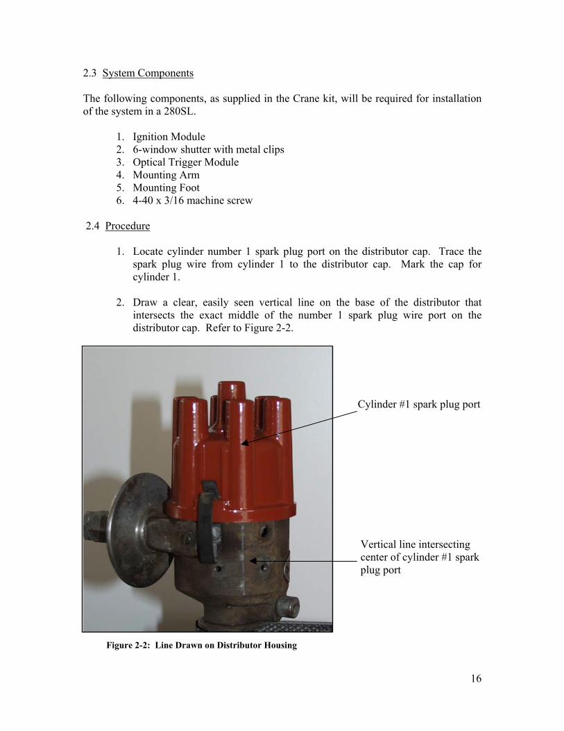
1. Locate cylinder number 1 spark plug port on the distributor cap. Trace the spark plug wire from cylinder 1 to the distributor cap. Mark the cap for cylinder 1.
2. Draw a clear, easily seen vertical line on the base of the distributor that
intersects the exact middle of the number 1 spark plug wire port on the distributor cap. Refer to Figure 2-2.
Cylinder #1 spark plug port Vertical line intersecting center of cylinder #1 spark plug port
Figure 2-2: Line Drawn on Distributor Housing
17
CAUTION: The line must be exactly in the center. If you place the line correctly, it will save you a lot of grief later.
3. Remove the distributor cap.
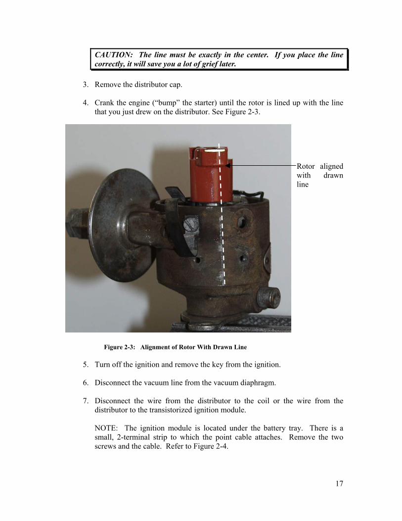
4. Crank the engine (“bump” the starter) until the rotor is lined up with the line
that you just drew on the distributor. See Figure 2-3. Rotor aligned with drawn line
Figure 2-3: Alignment of Rotor With Drawn Line
5. Turn off the ignition and remove the key from the ignition.
6. Disconnect the vacuum line from the vacuum diaphragm.
7. Disconnect the wire from the distributor to the coil or the wire from the distributor to the transistorized ignition module.
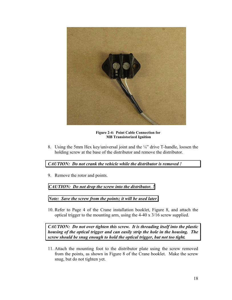
NOTE: The ignition module is located under the battery tray. There is a small, 2-terminal strip to which the point cable attaches. Remove the two screws and the cable. Refer to Figure 2-4.
18
Figure 2-4: Point Cable Connection for MB Transistorized Ignition
8. Using the 5mm Hex key/universal joint and the ¼” drive T-handle, loosen the
holding screw at the base of the distributor and remove the distributor.
CAUTION: Do not crank the vehicle while the distributor is removed !
9. Remove the rotor and points.
CAUTION: Do not drop the screw into the distributor. ! Note: Save the screw from the points; it will be used later. 10. Refer to Page 4 of the Crane installation booklet, Figure 8, and attach the
optical trigger to the mounting arm, using the 4-40 x 3/16 screw supplied.
CAUTION: Do not over tighten this screw. It is threading itself into the plastic housing of the optical trigger and can easily strip the hole in the housing. The screw should be snug enough to hold the optical trigger, but not too tight.
11. Attach the mounting foot to the distributor plate using the screw removed
from the points, as shown in Figure 8 of the Crane booklet. Make the screw snug, but do not tighten yet.

19
Note: Due to the small space inside the distributor, the optical trigger and shutter will have to be installed together. You cannot install the shutter if the optical trigger is already in place.
12. Install the shutter and optical trigger in the distributor. Carefully place the
shutter on the distributor camshaft, then install the rotor and use it to push down the shutter to the proper position. Fasten the mounting arm to the mounting foot with the 6-32 x ¼” screw supplied. Make the screw snug, but do not tighten.
13. Using a screwdriver, move the breaker plate (plate to which the optical trigger
is attached) to see if it moves freely. It will be hard to move, but neither the mounting arm or mounting foot of the optical trigger should touch the side of the distributor; the plate MUST move freely or the vacuum advance and retard will not function properly.
14. If the optical trigger assembly touches the side of the distributor, it will be
necessary to file the mounting arm and foot until enough clearance is achieved.
15. Install a rubber grommet in the hole through which the point wire used to
pass.
16. Route the three wires from the optical trigger through the grommet. Ensure that there is enough slack in the wires to allow the breaker plate to move freely.
17. Place a small bead of RTV self-vulcanizing rubber in the grommet to seal the
hole from external dust and debris.
18. Set the distributor aside and wait about 1 hour for the RTV to cure.
19. Install the ignition module in a suitable location. Use four, #8 sheet metal screws to secure the module. Tighten the screws securely and make sure that the module is lying flat on the mounting surface. Do not tighten the screws if the module is not flat or you will bend and deform the module enclosure, possibly causing internal damage.
Note: If you can find a suitable location that affords sufficient airflow for the ignition module, then use it. If you want to install the ignition module in the same manner as the author, refer to Section 3.0 for additional instructions, before proceeding.
20
20. Locate the ballast resistor that is installed in the vehicle. If you do not have the Mercedes Benz transistorized ignition system in your car, there will be one ballast resistor mounted on the driver’s side fender. The resistance of this resistor is 0.6 Ohms. If there is only one resistor on the fender, do not remove it.
If you have the Mercedes Benz transistorized ignition installed in your vehicle, there will be two ballast resistors; one will have a resistance of 0.6 Ohms and the other 0.4 Ohms. Remove the 0.4 Ohm resistor but do not remove the 0.6 Ohm resistor. Leave all removed wires and/or terminals open.
21. By now, the RTV should be cured in the distributor. In the following steps,
you will align the optical trigger, place the housing on the wire terminals and adjust the phasing of the optical trigger.
22. Remove the ignition module from the car.
23. Find the white, Teflon connector housing supplied with the Crane kit.
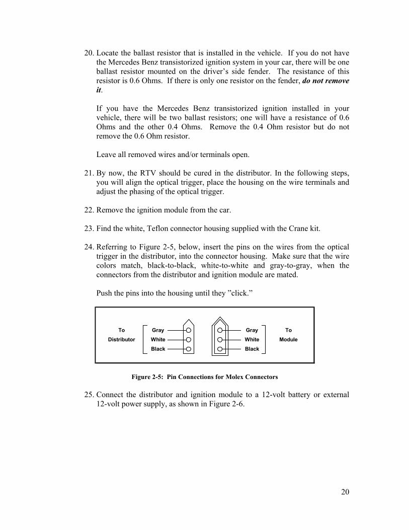
24. Referring to Figure 2-5, below, insert the pins on the wires from the optical
trigger in the distributor, into the connector housing. Make sure that the wire colors match, black-to-black, white-to-white and gray-to-gray, when the connectors from the distributor and ignition module are mated.
Push the pins into the housing until they ”click.”
Figure 2-5: Pin Connections for Molex Connectors
25. Connect the distributor and ignition module to a 12-volt battery or external
12-volt power supply, as shown in Figure 2-6.
ToModule
Black
GrayWhiteBlack
ToDistributor
GrayWhite

21
Figure 2-6: Set-up for Optical Trigger Alignment
26. Rotate the distributor shaft and ensure that the shutter moves freely in the slot
of the optical trigger. There should be no binding or scraping. If there is, you must file the brackets or readjust the optical trigger position. Once the shutter moves freely, you can begin the alignment of the optical trigger’s position.
27. Find the red LED on the ignition module housing. The LED may or may not
be illuminated.
28. Slowly – very slowly – rotate the distributor shaft while observing the LED on the module. Set the distributor rotor to align with the drawn line on the distributor housing.
29. Adjust the mounting arm and optical trigger until the LED illuminates when
the rotor is centered – exactly – on the drawn line, as shown in Figure 2-6, above.
30. Repeat this process several times and ensure that the LED illuminates when
the rotor is exactly centered on the drawn line. Tighten the screw on the mounting arm and the screw holding the mounting foot.
31. Repeat step 29 and make sure that the LED still illuminates when the rotor is
exactly centered on the drawn line.
32. Disconnect all equipment and unplug the connection between the distributor and ignition module.
33. Reinstall the distributor in the vehicle and snug-up the 5mm holding bolt.
GrayDrawn Line White Red LED
Black
Black wire Red wire
- +Distributor Do not connect the
yellow wire
IGNITION MODULE
12-Volt Battery or Power Supply

22
34. Install the distributor cap and ensure that all spark plug wires are in the proper ports. The firing order is 1-5-3-6-2-4 and the distributor shaft rotates in a clockwise direction, as viewed from above; refer to Figure 2-7.
Figure 2-7: Firing Order
Distributor Top View
35. You must now determine which wires carry the proper voltages to operate the ignition system. Earlier, you identified the ballast resistors on the interior fender wall. If your vehicle does not have the Mercedes Benz transistorized ignition system installed, refer to Figure 2-8. If your vehicle does have the Mercedes Benz transistorized ignition system installed, refer to Figure 2-9.
Figure 2-8: Wiring for Vehicles without MB Transistorized Ignition
1
5
3
6
2
4
+12 Volts when engine is crankingTo terminal 16
of starter solenoid
terminal (15) of
ignition coil
switch (ON/RUN)Black/Green
Red/Violet
Red/Black
Ballast Resistor, 0.6 Ohms
+12 Volts
from Ignition To positive (+)
23
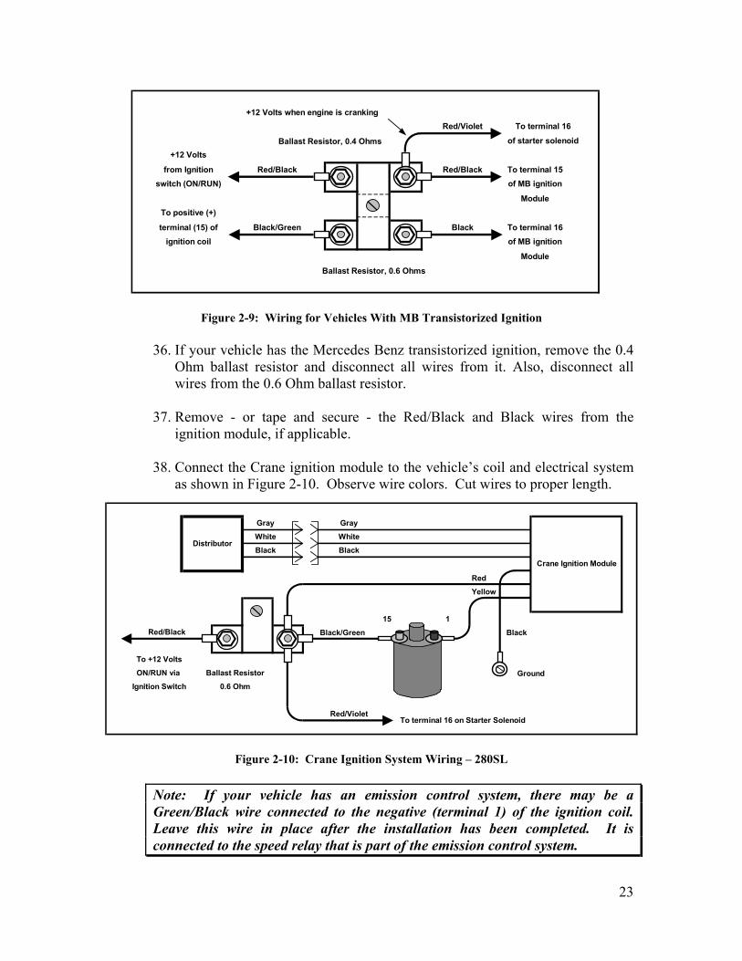
Figure 2-9: Wiring for Vehicles With MB Transistorized Ignition
36. If your vehicle has the Mercedes Benz transistorized ignition, remove the 0.4
Ohm ballast resistor and disconnect all wires from it. Also, disconnect all wires from the 0.6 Ohm ballast resistor.
37. Remove - or tape and secure - the Red/Black and Black wires from the
ignition module, if applicable.
38. Connect the Crane ignition module to the vehicle’s coil and electrical system as shown in Figure 2-10. Observe wire colors. Cut wires to proper length.
Figure 2-10: Crane Ignition System Wiring – 280SL
Note: If your vehicle has an emission control system, there may be a Green/Black wire connected to the negative (terminal 1) of the ignition coil. Leave this wire in place after the installation has been completed. It is connected to the speed relay that is part of the emission control system.
+12 Volts when engine is cranking
Ballast Resistor, 0.4 Ohms
To positive (+)
terminal (15) ofignition coil
Ballast Resistor, 0.6 Ohms
To terminal 16of MB ignition
Module
BlackBlack/Green
Module
of starter solenoidTo terminal 16
Red/Black
Red/Violet
To terminal 15of MB ignitionswitch (ON/RUN)
Red/Blackfrom Ignition
+12 Volts
RedYellow
15 1Black/Green Black
Ground
To +12 Volts
Crane Ignition Module
Red/Black
Red/Violet
GrayWhiteBlack
GrayWhiteBlack
Distributor
Ballast Resistor0.6 Ohm
To terminal 16 on Starter Solenoid
Ignition SwitchON/RUN via

24
Note: If you wish to shorten the wires to the distributor, you will have to remove the Teflon connector housing on either the cable from the ignition module or the cable from the distributor. Proceed as follows:
a. Locate the pin removal tool supplied with the Crane kit; it looks like a
small brass tube about 2-1/2” long.
b. Place the hollow tool over the pin you wish to remove and push firmly; the pin will come out of the shell. Repeat for the remaining two pins.
c. Cut the cable to the length desired. Leave enough length to allow the
connectors to be unmated if maintenance is required.
d. Strip about ¼” of insulation from the end of all three wires.
e. Acquire the proper pins – male or female – from a Waldom/Molex distributor; Radio Shack usually handles the pins. You will need 0.093” diameter pins.
f. Using a Waldom/Molex crimping tool, Model HT1919 or equivalent,
crimp the terminals onto the wires. Note that two crimps will be required for each pin. The first crimp secures the wire electrically and the second secures the wire physically.
g. Insert the pins into the connector shell. Ensure that the colors match –
side-to-side – when the connectors are mated.
h. Dress and secure the cable to the existing harness with ty-wraps.
39. Retain the 0.4 ohm ballast resistor; it may be needed later.
40. Unless already accomplished, remove the Mercedes Benz transistorized ignition module from beneath the battery shelf, if applicable.
41. Connect a timing light to the battery and spark plug wire for cylinder #1.
42. Connect an electronic tachometer to the negative (terminal 1) of the ignition
coil.
43. Start the engine and set the timing to the specifications for your vehicle and gasoline octane used.
44. Connect a voltmeter between any ground point and the positive (terminal 15)
of the ignition coil.

25
45. Run the engine at a constant 1,500 RPM and note the reading on the voltmeter. It should read between 10.2 and 11.3 volts. If the voltage is too low, replace the ballast resistor with a 0.4 Ohm unit and retest. If the voltage is too high, install a 0.7 or 0.8 Ohm resistor and retest. Resistors can be obtained from any Bosch dealer.
46. Road test the vehicle at engine RPM at or near red line. The vehicle should
exhibit smooth acceleration with no misfiring.
47. Route or dress all wires and secure to the existing wiring harness with ty-wraps. Use of electrical tape is not recommended. Tape tends to melt and lose its adhesion under high temperatures.
48. The installation is now complete. If you encounter any problems, follow the
troubleshooting procedures on page 19 of the Crane booklet. 2.5 Additional Procedures If you wish to mount the Crane ignition mount in the same manner as the author, please refer to Section 3.0 for additional instructions.

26
3.0 OPTIONAL INSTALLATION INSTRUCTIONS This section describes the procedures to be used if the user wishes to mount the Crane Ignition Module above the left-front sub-frame mount, as did the author. This will require an aluminum mount plate and also drilling and tapping four holes in the metal plate that surrounds the shock absorber mounting bolt. 3.1 Manufacturing the Mounting Plate Fashion a mounting plate from 0.050” 2024 (soft) aluminum. The aluminum can be acquired from any sheet metal shop. Cut and drill the plate as shown in Figure 3-1. File and de-burr all edges; round each corner. Paint the panel if you wish, using high-temperature flat black paint. A suitable type is the black paint used for wood stoves and furnaces.
Figure 3-1: Ignition Module Mounting Plate
3.2 Assembling the Mounting Plate and Spacers Fasten the spacers to the mounting plate using four 6-32 x ½” screws and four #6 internal tooth lock washers. Tighten the screws securely but do not over tighten.
1/2" 7/16"
Aluminum: 0.050" 2024All holes: 9/64"Dark holes for spacersClear holes for module
1/4" 3/8" 3/8"
4"
4"
1/4"2-1/16"
1-15/16"
1-1/4" 2"
2-7/
8"

27
3.3 Marking, Drilling and Tapping the Mounting Holes
1. Place the mounting plate with the spacers attached in the space above the sub-frame mount. See Figure 3-2.
Spacers
Figure 3-2: Location for Mounting Plate Above Sub-Frame Mount 2. Adjust the plate so that each spacer is resting firmly on a flat surface.
3. Hold the plate firmly in place and mark around each spacer to identify the drill
location.
4. Drill a 7/64” hole in the center of each mark made (four holes).
5. Thread each hole using a 6-32 tap. Lubricate the tap with 3-in-one oil or similar.
6. Insert a 6-32 screw into each hole and ensure that the hole threads are correct.
7. Clean away any excess oil and metal shavings. 3.4 Installing the Mounting Plate
1. Remove the spacers from the mounting plate. 2. Using a standard crimper/bolt cutter tool, cut the heads off of four, 6-32 x 1”
machine screws. The screws should be steel or stainless steel.

28
3. Remove the screws from the bolt cutter and ensure that the threads on the cut ends are smooth and functional.
4. Insert the cut ends of the bolts into each of the four spacers. Turn the screws
until they stop; about 3/8” to 7/16”. About 5/8” of the screw should be protruding from the spacer. Refer to Figure 3-3.
Figure 3-3: Placing Screws Into
The Spacers
5. Place a #6 internal tooth lock washer on each of the four protruding screws and screw them into the four holes previously drilled.
6. Tighten each spacer with a nut driver or wrench. Tighten firmly.
7. Insert four 6-32 x 1” screws into the mounting plate as shown in figure 3-4.
Tighten all nuts. Use the holes for the ignition module (See Figure 3-1, above).
Figure 3-4: Module Mounting Screws Detail
8. Fasten the mounting plate to the four previously installed spacers. Use four 6-32
x ½” screws and four #6 internal tooth lock washers. Refer to Figure 3-5 to see the mounting plate installed in the vehicle.
Spacer
Cut end of screw
5/8"
6-32 x 5/16" nut #6 Lock Washer
#6 Lock Washer 6-32 x 1" Screw
Mounting Plate

29
Figure 3-5: Mounting Plate Installed 3.5 Installing the Crane Ignition Module
Attach the Crane ignition module to the mounting plate using four #6 internal tooth lock washers and four 6-32 x ¼” nuts. Tighten the nuts securely. Refer to Figure 3-6 to see the Crane ignition module installed in the vehicle.
Figure 3-6: Crane Ignition Module Installed Installation of the ignition module is complete; return to Section 2.0 for wiring and testing.