heterogeneous teams of modular robots for mapping and
TRANSCRIPT

1
Heterogeneous Teams of Modular Robots forMapping and Exploration
Robert Grabowski, Luis E. Navarro-Serment, Christiaan J.J. Paredis, Pradeep K. Khosla
Institute for Complex Engineered Systems,The Robotics Institute, and
Department of Electrical and Computer EngineeringCarnegie Mellon University
Pittsburgh, Pennsylvania 15213{grabowski, lenscmu, cjp, pkk}@cs.cmu.edu
Abstract
In this article, we present the design of a team of heterogeneous, centimeter-scale robots thatcollaborate to map and explore unknown environments. The robots, called Millibots, areconfigured from modular components that include sonar and IR sensors, camera, communication,computation, and mobility modules. Robots with different configurations use their specialcapabilities collaboratively to accomplish a given task. For mapping and exploration with multiplerobots, it is critical to know the relative positions of each robot with respect to the others. We havedeveloped a novel localization system that uses sonar-based distance measurements to determinethe positions of all the robots in the group. With their positions known, we use an occupancy gridBayesian mapping algorithm to combine the sensor data from multiple robots with different sensingmodalities. Finally, we present the results of several mapping experiments conducted by a user-guided team of five robots operating in a room containing multiple obstacles.
1 Introduction
A team of robots has distinct advantages over single robots with respect to sensing as well asactuation [1][19]. When manipulating or carrying large objects, a given load can be distributed overseveral robots so that each robot can be built much smaller, lighter, and less expensive [24][25]. Asfor sensing, a team of robots can perceive its environment from multiple disparate viewpoints. Insuch a system, a task is not completed by a single robot but instead by a team of collaboratingrobots. Team members may exchange sensor information, help each other to scale obstacles, orcollaborate to manipulate heavy objects. A single robot, on the other hand, can only sense itsenvironment from a single viewpoint, even when it is equipped with a large array of differentsensing modalities. There are many tasks for which distributed viewpoints are advantageous suchas, surveillance, monitoring, demining and plume detection.
Distributed robotic systems require a new design philosophy. Traditional robots are designed witha broad array of capabilities (sensing, actuation, communication, and computation). Often, thedesigners will even add redundant components to avoid system failure from a single fault. The

2
resulting systems are large, complex, and expensive. For robot teams, the design can be approachedfrom a completely different angle, namely: "Build simple inexpensive robots with limitedcapabilities that can accomplish the task reliably through cooperation." Each individual robot maynot be very capable, but as a team they can still accomplish useful tasks. This results in lessexpensive robots that are easier to maintain and debug. Moreover, since each robot is expendable,reliability can be obtained in numbers; that is, if a single robot fails, little if any capabilities are lost,and the team can still continue the task with the remaining robots.
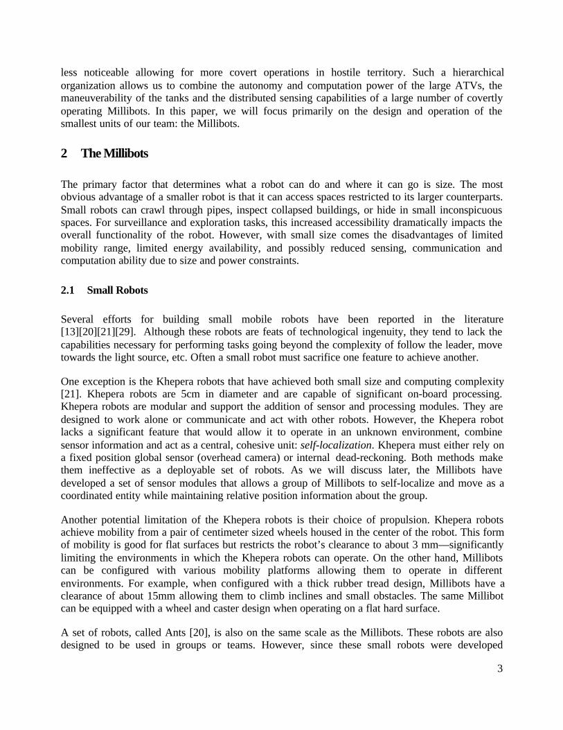
Because the size of a robot determines to a large extent its capabilities, we are developing ahierarchical robot team at Carnegie Mellon University. As is shown in Figure 1, the team consistsof large All Terrain Vehicles (ATVs) [6][9], medium-sized Tank robots (based on a remote controlTamiya tank model) [5], a set of Pioneer robots and centimeter scale Millibots (7×7×7cm). TheATVs have a range of up to 100 miles, are completely autonomous and carry extensivecomputational power. They are capable of transporting and deploying groups of smaller robots todistant areas of interest while providing higher-level computational support of the extended team.The Pioneer robots are platforms for the development of "Port-Based Adaptive Agents" [8] thatwill allow the team to dynamically exchange algorithms and state information while on-line. TheTank robots are medium-sized, autonomous robots complete with infrared and sonar arrays, aswivel-mounted camera and an on-board 486 computer. Each tank robot is capable of individualmissions or can serve as the leader and coordinator for a team of smaller, centimeter-scale robotscalled Millibots. These small and lightweight robots can be easily carried by their largercounterparts higher-up in the robot hierarchy. They can maneuver through small openings and intotight corners to observe areas that are not accessible to the larger robots. Being small, they are also
30x50cm
Figure 1: A hierarchical team of robots consisting of
Millibots (top), Tanks, Pioneers and ATVs
3
less noticeable allowing for more covert operations in hostile territory. Such a hierarchicalorganization allows us to combine the autonomy and computation power of the large ATVs, themaneuverability of the tanks and the distributed sensing capabilities of a large number of covertlyoperating Millibots. In this paper, we will focus primarily on the design and operation of thesmallest units of our team: the Millibots.
2 The Millibots
The primary factor that determines what a robot can do and where it can go is size. The mostobvious advantage of a smaller robot is that it can access spaces restricted to its larger counterparts.Small robots can crawl through pipes, inspect collapsed buildings, or hide in small inconspicuousspaces. For surveillance and exploration tasks, this increased accessibility dramatically impacts theoverall functionality of the robot. However, with small size comes the disadvantages of limitedmobility range, limited energy availability, and possibly reduced sensing, communication andcomputation ability due to size and power constraints.
2.1 Small Robots
Several efforts for building small mobile robots have been reported in the literature[13][20][21][29]. Although these robots are feats of technological ingenuity, they tend to lack thecapabilities necessary for performing tasks going beyond the complexity of follow the leader, movetowards the light source, etc. Often a small robot must sacrifice one feature to achieve another.
One exception is the Khepera robots that have achieved both small size and computing complexity[21]. Khepera robots are 5cm in diameter and are capable of significant on-board processing.Khepera robots are modular and support the addition of sensor and processing modules. They aredesigned to work alone or communicate and act with other robots. However, the Khepera robotlacks a significant feature that would allow it to operate in an unknown environment, combinesensor information and act as a central, cohesive unit: self-localization. Khepera must either rely ona fixed position global sensor (overhead camera) or internal dead-reckoning. Both methods makethem ineffective as a deployable set of robots. As we will discuss later, the Millibots havedeveloped a set of sensor modules that allows a group of Millibots to self-localize and move as acoordinated entity while maintaining relative position information about the group.
Another potential limitation of the Khepera robots is their choice of propulsion. Khepera robotsachieve mobility from a pair of centimeter sized wheels housed in the center of the robot. This formof mobility is good for flat surfaces but restricts the robot’s clearance to about 3 mm—significantlylimiting the environments in which the Khepera robots can operate. On the other hand, Millibotscan be configured with various mobility platforms allowing them to operate in differentenvironments. For example, when configured with a thick rubber tread design, Millibots have aclearance of about 15mm allowing them to climb inclines and small obstacles. The same Millibotcan be equipped with a wheel and caster design when operating on a flat hard surface.
A set of robots, called Ants [20], is also on the same scale as the Millibots. These robots are alsodesigned to be used in groups or teams. However, since these small robots were developed

4
primarily to explore reactive social behaviors they are very limited in sensing. They do not supporta real-time communication link nor are they equipped to exchange sensor information necessary toproduce maps or models of the environment. Rather they are designed to convey simple messagessuch as “have food” or “it” via a short-range infrared transmitter, sense objects with a simple touchswitch and sense orientation with a simple light detector. Millibots, on the other hand, are equippedwith various sensor arrays such as a multi-element sonar and on-board video that provide moredetailed information. These sensors are capable of identifying objects and building maps of theenvironment.
To achieve their scale, the Ants were built with a fixed architecture. Propulsion, sensing andprocessing are combined to optimize size constraints such that the addition of any new functionalitywould require a complete redesign. The Ants suffer from the inability to localize as well. They relyon the presence of a strong light source for orientation and encoders for dead-reckoning. Even ifthey were able to communicate more detailed information between them, without a means fordetermining position, they would have little context in which to evaluate the data.
Examples of small-scale cooperating robots are the FIRA and RobotCup competitions (Federationof International Robot-soccer Association) [29]. Each team of soccer robots consists of a group offive robots that are limited in size to 7.5×7.5×7.5 cm. These robots coordinate to perform complexactions like passing a ball and defending a goal against a coordinated attack. Like Millibots, theteam of soccer robots acts as a set of distributed mobility platforms tasked by a central controller.However, most soccer robot teams are extremely limited in their sensing capabilities. Positionsensing for the soccer robots is accomplished via a global camera positioned above the playingfield. Most teams have little or no sensors on the robots themselves. Without the external camera,the robots are blind and unable to respond to real-world events.
The examples discussed above illustrate some of the limitations imposed by small scale. Smallrobots must sacrifice mobility, sensing and power to achieve their desired scale. To remaineffective, they must adopt new techniques to overcome these limitations.
3 Specialization and Collaboration
Our approach to overcoming the disadvantages imposed by small robots is based on specializationand collaboration (section 4). Specialization is achieved by exploiting the nature of aheterogeneous team. Instead of equipping every robot with every sensor, computation, andcommunication capability, we are building robots that are each specialized for a particular aspect ofthe task. In one type of scenario, the robot team may be composed of robots with various range andposition sensors but only limited computation capabilities. In this case, the robots act as distributedsensor platforms remotely controlled by a team leader who performs the high-level planning. Inanother task, the same group of Millibots may be equipped with more computation. Data can becollected and stored locally until it is ready to be retrieved. Some missions may dictate a collectionof robots of differing strengths. The choice of platforms and how the platforms are used dependsonly on the task.
By omitting the capabilities that are unnecessary for a particular scenario, power, volume, andweight of the robot can significantly be reduced. However, specialization has the disadvantage that
5
many different robots need to be available to address the specific requirements of a given task.
3.1 Modular Architecture
To achieve this level of specialization without the need for a large repository of robots, we havechosen to develop the Millibots in a modular fashion. A Millibot is constructed by assembling a setof sub-systems ranging from computation to communications to sensors. Even the mobilityplatform is modular and can be selected based on the terrain of the mission. To support modularity,each of the subsystems has been implemented as a self-contained module complete with processorand interface circuitry.
Specialization through modularity also allows the Millibots to optimize resources. By constructinga robot with only mission specific modules, the size and cost of the robot can be kept to aminimum. Reduction of unnecessary payload means the robot will have less weight and consumeless power. Furthermore, some robots require less computational complexity allowing them to beequipped with smaller processors that in turn consume less power. Smaller and cheaper means thatrobots can be built and deployed in large numbers to achieve dense sensing coverage, team leveladaptability, and fault tolerance.
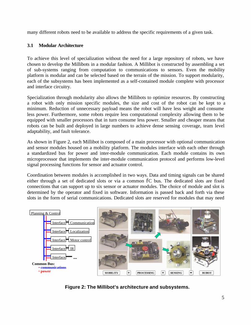
As shown in Figure 2, each Millibot is composed of a main processor with optional communicationand sensor modules housed on a mobility platform. The modules interface with each other througha standardized bus for power and inter-module communication. Each module contains its ownmicroprocessor that implements the inter-module communication protocol and performs low-levelsignal processing functions for sensor and actuator control.
Coordination between modules is accomplished in two ways. Data and timing signals can be sharedeither through a set of dedicated slots or via a common I2C bus. The dedicated slots are fixedconnections that can support up to six sensor or actuator modules. The choice of module and slot isdetermined by the operator and fixed in software. Information is passed back and forth via theseslots in the form of serial communications. Dedicated slots are reserved for modules that may need
Planning & Control
Common Bus:• communications• power
Communication
Localization
Motor control
IR
Interface
Interface
Interface
Interface
Interface
...
Figure 2: The Millibot’s architecture and subsystems.

6
additional data lines or cannot handle the computational complexity of I2C.
An I2C bus [17] provides a second option for connection of modules. I2C is a bus design andcommunications protocol that allows multiple modules to be connected to a common two-wire bus.One wire provides a high speed, synchronous clock while the other provides a two-way datacommunication line. Target modules are distinguished from one another by pre-appending eachmessage on the data line with an address header. Only the module that matches the address acts onthat message This interface is less restrictive than the dedicated slot method because it allows manymodules to be connected to the same processor without having to designate on which pins themodules reside. The choice of which type of connection is determined by the operator and easilyconfigured in software.
Any module that does not violate the size and power constraints of the Millibots and provides aserial interface for data exchange can utilized by the Millibot. Sensor modules of this type includeranging sensors, proximity detectors, chemical sensors, magnetic field detectors, and radiationmonitors.
3.2 The Millibot subsystems
Currently the Millibots can be composed from a suite of seven subsystems: the main processormodule, a communication module, an IR obstacle detection module, two types of sonar modules, amotor control module, and a localization module.
Communications is essential in a coordinated team. Without explicit communications, a robot canonly interact with team members using its sensors (e.g. vision-based “follow the leader” behavior)[4] [19]. However, collaborative mapping and exploration requires the exchange of detailed andabstract information that cannot be easily conveyed implicitly. To provide two-waycommunications within the group, each Millibot is equipped with a radio frequency transmitter andreceiver. These units can exchange data at 4800 bps at a distance of up to 100 meters. The choice ofunits is based primarily on size and power considerations Units with higher data transfer rates existbut at the prohibitive cost of size. This tradeoff between size and functionality is a common themein constructing small robots. We expect that smaller more powerful transmission units will becomecommercially available in the future as miniaturization in solid state progresses.
To perceive the world, a robot must have sensors. There are currently three sensor modulesavailable to each Millibot. The first two are a set of ultrasonic sonar modules that provide focusedrange information about obstacles. One sonar module type provides short-range distanceinformation for obstacles between 0 and 0.5m. The module consists of eight sonars arranged in aring around the center of the robot. Though limited in range, this module provides detailedinformation about the area directly surrounding the robot. A short-range sensor module such as thisis ideal for Millibots that have to work in tight or cluttered areas. For robots at this scale, the abilityto measure extremely short range is essential.
The second sonar module type provides long-range information for obstacles between 0.15m and1.8m. Long-range sensors are more effective in environments that are more open such as hallwaysor open office spaces. Because of the construction of this type of detector, a Millibot can currently

7
support only one sonar pair per robot. This unit can return long-range distance information but in atightly focused cone of only 40 degrees. To obtain more complete information about theenvironment, this type of detector would have to rely on movement of the robot to increasecoverage. For some tasks, it may be desirable to have both short and long-range sonar sensingavailable. This can still be achieved by equipping some Millibots on the team with short-rangemodules and some with long-range sonar modules.
A potential complication with any ultrasonic based sensor is the probability of interference withsimilar modules on other robots. Most sonar elements operate at a fixed frequency determined bytheir mechanical construction. Therefore, two robots using ultrasonic sensors in the same area willmost likely cause interference for the other. To overcome this problem while still providingcontinuous rudimentary obstacle detection, a Millibot may opt to carry an infrared proximitymodule. The proximity module provides an array of five tunable, infrared emitter-detector pairsthat trigger when an obstacle intrudes within its cone of emission. The proximity elements can becalibrated to provide readings of up to 0.25m. Although the proximity detectors cannot be reliablyused for range determination of objects, they can be used very effectively in conjunction with asonar detector module. The proximity module can be continuously sensing an area around therobot. Upon detection of an object by the proximity detector, the robot can coordinate with the teamto acquire better range information through its sonars.
Except under the most controlled conditions, the sensors discussed so far cannot provide enoughdetail to resolve many of the problems facing a real robot. Real situations are fraught withanomalies. A method is needed to provide high bandwidth information during a mission foranalysis by a higher level process or operator. To provide this service, Millibots can be equippedwith a camera module. The camera module provides an external mini camera, video transmitter andpower circuitry. Currently because of the limited processing capabilities of the Millibot, videosignals cannot be processed on-board. A small video transmitter is included with the module totransmit the raw video signal to an external processor or remote viewing station. The cameramodule includes circuitry that allows the camera and its transmitter to be switched on and off viacontrol signals from the Millibot. Control of the camera aids in effective power management. Thecamera need only be powered when an image is desired. The ability to remotely power down anindividual transmitter also allows multiple robots to carry similar camera modules while using thesame transmitter frequency. Interference is prevented by powering only one transmitter at a time.Additionally resources are minimized since only one receiving station and associated monitoringdevice is needed per Millibot group. However, though the camera module provides valuable visualinformation, it operates on the threshold of the Millibot’s power budget. The current cameradissipates about 1.5 Watts of power during operation. Due to the limited size of the battery, thistype of sensor cannot be used continuously like other sensor packages.
Not all scenarios will support robots designed with the same modes of propulsion. For example, asmall robot equipped with a set of thin rubber tracks will perform well on a flat, slippery surface,such as a floor or table but performs poorly on a shag rug. Conversely, the same robot mayoutperform a robot equipped with wheels in another scenario. In the Millibot group, modularity hasbeen extended to the mobility platforms as well. A mobility platform is selected for a particularMillibot and the main processor and its set of support sensors is added to make it a robot. In mostcases, the mobility platforms will utilize a similar set of dc motors. Therefore, the same motorcontrol module can be selected and only the software needs to be changed. For platforms that

8
differ, they need only to include their own motor control module and conform to the softwareinterface. Currently the Millibots have implemented three sets of platforms each utilizing skidsteering. Some Millibots are equipped with a plastic chain design which is ideal for rough surfaceslike rugs while others are equipped with rubber tread designs of differing widths which allows themto crawl on smooth inclined surfaces.
4 Collaboration
In addition to specialization, Millibots use collaboration to overcome the limitations imposed bysmall scale. By nature, Millibots are small, mobile robots with limited capabilities. Yet, bycollaborating with each other as a team, they are able to overcome their individual limitations andaccomplish important tasks ranging from localization to surveillance, mapping, and exploration.
When distributed robotic applications require robots to share sensor information (e.g. mapping,surveillance, etc.) it is critical to know the position and orientation of the robots with respect toeach other. Without this knowledge, it becomes impossible to interpret the sensor data in a globalframe of reference and integrate it with data obtained by other robots. Millibots exploitcollaboration to obtain relative position and orientation of the team with respect to each other, evenas the team moves. Without an external means of localization, this knowledge is essential for theteam to move to predetermined locations, avoid known obstacles, or reposition themselves formaximum sensor efficiency.
Conventional localization systems do not offer a viable solution for Millibots. Dead reckoning, acommon localization method, generally suffers from accuracy problems due to integration errorsand wheel slippage [3]. This is even more pronounced for systems that rely on skid steering forwhich track slippage is inherent to the steering mechanism. Camera-based localization, such as
Figure 3 : Ultrasonic distance measurement.

9
those used by the soccer robots, is not feasible in many of the environments in which small robotscan be exploited. On the other hand, larger robotic systems often rely on Global PositioningSystems (GPS) and compass for determining their position and orientation in a global frame ofreference [12]. However, due to its size, limited accuracy, and satellite visibility requirements, GPSis not appropriate for use in small robots that operate mostly indoors. Conversely, systems that arebased on landmark recognition [2][15] or map-based positioning [27] require excessive localcomputational power and sensing accuracy to be implemented on Millibots.
To overcome the problems encountered in the implementation of existing localization methods fora team of Millibots, we have developed a novel method that combines aspects of GPS, land-markbased localization, and dead reckoning [23]. This method uses synchronized, ultrasound pulses tomeasure the distances between each robot on a team and then determines the relative positions ofthe robots through trilateration. Similar systems have been developed [14]. However, they are bothtoo large and too expensive for operation on Millibots. Moreover, the system described in thisarticle is more flexible because it does not require any fixed beacons with known positions, whichis an important relaxation of the requirements when mapping and exploring unknownenvironments.
4.1 Collaborative Localization
The Millibot localization system is based on the trilateration [3], i.e., determination of the positionbased on distance measurements to known landmarks or beacons [16] [18]. GPS is an example of atrilateration system; the position of a GPS unit on earth is calculated from distance measurementsto satellites in space. Similarly, the Millibot localization system determines the position of eachrobot based on distance measurements to stationary robots with known positions.
To derive team positions, each Millibot is equipped with a localization module that utilizesultrasound and radio pulses to measure the distances between it and other robots. Each localizationmodule is designed to act as both emitter and receiver. Periodically, each module emits a series oflocalization pulses that emit radially away from the robot. To synchronize the timing betweenrobots without having to use accurate timers, each module actually emits both a radio frequency(RF) pulse and a series of ultrasonic pulses. As is illustrated in Figure 3, The RF pulse, traveling atthe speed of light (3×10⁸ m/s), arrives at each receiver almost instantaneously. The ultrasonic
x
Acousticreflector
Ultrasonic transducer
Incomingultrasonicsignals
zy
Figure 4 : The acoustic reflector

10
pulses, traveling only at 343 m/s (assuming 20°C air temperature), arrive at each receiver delayedby a time proportional to its distance to the emitter. The timing between each robot pair is storedlocally by the module until it can be reported to the team leader.
Following each sequence, the team leader collects the timing information between each pair. Thisinformation is used to determine the actual position of every Millibot using a maximum likelihoodestimator. In the future, we plan to calculate the Millibot positions on the local processor of eachMillibot. However, the current processor does not have the necessary computation power toperform these floating-point computations.
To produce and detect beacon signals, each Millibot is equipped with a modified, low-costultrasonic transducer. This transducer can function either as a receiver or as an emitter. Forlocalization to be effective, it is important that the sensor is able to detect signals coming from anydirection around the Millibot. As illustrated in Figure 4, an ultrasonic transducer is positioned toface straight up and all incoming and outgoing sound waves are reflected by the aluminum cone.The result is a detector with a coverage of 360 degrees in the horizontal plane. The ultrasonictransducer with reflector is about 2.5cm tall. It can measure distances up to 3m with a resolution of8mm while consuming only 25mW. The construction and design of this detector was paramount inachieving a localization system at this scale.
4.2 The Localization Algorithm
To determine the position and orientation of the robots relative to each other, we use a maximumlikelihood estimator. If all the distance measurements were perfectly accurate, we could use asimple geometric trilateration algorithm to determine the position of the robots relative to eachother. However, measurements are noisy and sometimes missing. As a result, the set of equationsresulting from a purely geometric approach is over-constrained and does not always yield asolution. Instead, we use a maximum likelihood estimator that determines the most likely positionand orientation of all the robots, given their previous positions and orientations, their movements,and the sonar-based distance measurements.
Assume that we know the position an orientation, ),,( 000 ϕyx , of all the robots at time 0t . The
question is: how do we determine the position, ),,( 111 ϕyx , of the robots at time 1t , after they havemoved? We can estimate the new positions based on the following information:
• Dead reckoning : Since all the Millibots are equipped with encoders, their position at time1t can be estimated by integrating the encoder signals. This can be further simplified in our
case, because the Millibots always move according to “vector commands” (i.e., rotation inplace over an angle α , followed by a forward straight-line motion over a distance, d ). Astiff controller guarantees that the commanded motion, ),( dα , is realized, eliminating theneed to query the robot after the motion is completed. In addition to the parameters α andd , we assume that the vector command is characterized by the angle β . As is illustrated inFigure 5, β is the angle over which the robot rotates while moving forward. This unplannedrotation is due to wheel slippage and calibration errors in the controller. There is a one-to-

11
one mapping between the incremental motion of the robot, from ),,( 000 ϕyx to ),,( 111 ϕyx ,and the parameters ),,( dβα :
),(atan2 22),(atan2 2
22
xyxy
yxd
∆∆−∆=∆−∆∆=
∆+∆=
ϕβϕα (1)
• Distance measurements : After all the robots have come to a halt, each robot that movedpings its localization beacon to determine its distance to all the other robots. The resultingdistance measurements provide accurate data that allow us to overcome the drift typicallyencountered in localization algorithms based on dead reckoning alone.
We have carefully calibrated the motion controller and localization beacon so that, in addition tothe nominal measurement, we have an estimate of the corresponding standard deviation. Asillustrated in [23], the distribution of the localization data closely resembles a Normal distribution.Assuming that both the dead reckoning data and the distance measurements are normallydistributed, we can compute the likelihood of a particular set of measurements occurring for a givenrobot position:
• Dead reckoning : The likelihood that a robot moved over an angle, ασα ± , and a distance,
dd σ± , given its initial position ),,( 000 ϕyx and final position ),,( 111 ϕyx is:
)ˆ
()ˆ
()ˆ
(),,,,( 1111
djjii
ddNNNyxyxdP
σσββ
σαα
αβα
−−−= (2)
β2/β
d
αinitial
headingβ
2/β
d
αinitial
headinginitial
heading
Figure 5: Vector command, ),( dα , with the deviation from straight-line motion.

12
• Distance measurements: The likelihood that the measured distance between two robots, iand j , is equal to ijD is:
))()(
(),,,(211211
1111
D
jijiijjjiiij
yyxxDNyxyxDP
σ
−+−−= (3)
The total conditional likelihood function),,,,,,,,,,,,,,,,,( 1111
111
11
00001
01
01 nnnnnnijiitot yxyxyxyxDdP ϕϕϕϕα KKKK is the product of all the
conditional likelihoods introduced above. The most likely robot positions are found by maximizing
totP with respect to the new robot positions ),,,,,,( 11111
11
11 nnn yxyx ϕϕ K .
The maximum likelihood estimator requires that the initial positions of the robots are known withrespect to one another. This requires a slightly modified approach at start up. After collectingdistance measurements between all possible robot pairs, a conditional probability density functionis defined which only consists of distance measurement terms. In addition, one arbitrary robot isassigned the position (0,0) and a second robot is assigned a position on the X-axis. This defines aframe of reference in which the position of all other robots is determined by maximizing theconditional probability density function. However, based on distance measurements alone, thereremains an ambiguity about the sign of the Y-coordinates of each robot. To resolve this ambiguity,the team leader commands one robot to follow a short L-shaped trajectory and recomputes itsposition. If the robot turned to the left, but the assigned coordinate system indicates a right turn,the signs of the Y-coordinates of all robots are reversed.
4.3 Implementation Issues
The optimization of the conditional probability density function can be formulated as a weightednonlinear least-squares problem, which we solve using the BFGS nonlinear optimization algorithm[11]. The dead reckoning data provides a good starting point, so that only a few optimizationiterations are necessary to reach the optimum. During the initialization stage of the robot team,when no prior information about the robot positions is available, the BFGS algorithm may get stuckin a local minimum. Based on experimentation, we have found that taking the best-out-of-fiverandomly initialized runs never fails to find the global optimum.
To obtain good results with the above algorithm, it is very important to filter the raw measurementdata. Even though the sensors are very accurate and reliable, it is possible that they have returnedfalse measurements. This occurs for instances where the direct path between two robots isobstructed by an obstacle or another robot. The beacon sensors will always return the timecorresponding to the first incoming ultra-sound pulse. In this case, the first pulse is the result ofsome multi-path rather than the direct-path pulse. As a result, the measured distance can besignificantly larger than the actual distance. A similar error occurs when there is a multi-path pulsethat destructively interferes with the direct pulse. In this case, the ultrasonic pulse is not detected atall.

13
It should be noted that the difference between a good and a bad distance measurement cannot berecognized based on the measurement data alone. Indeed, multiple measurements will all result inthe same (possibly erroneous) reading. Erroneous readings can still be rejected, however, based ondead reckoning information. Even though dead reckoning is unreliable when integrated over a longtime, for a single robot action, it can provide a reasonable estimate of the robot’s position. Bycomparing the encoder distance measurements with the distances computed for the estimatedpositions, it is possible to reliably reject erroneous measurements due to multi-path.
Furthermore, the accuracy of the algorithm was improved significantly by using more than theminimally required three robot beacons. In our experiments, we used a team of five robots inwhich, at any time, four served as beacons. The extra distance measurements improve the accuracyof the position estimates, especially, when the direct path to one or more of the robot beacons isobstructed by obstacles. Further accuracy improvements were obtained by pinging each beaconmultiple times. Median and mean filtering were then used to significantly reduce the standarddeviation of the distance measurement, resulting in a more accurate position estimate.
5 Mapping and Exploration
The primary utility of the Millibots is exploration and mapping. The team coordinates movementsand collection of sensor data to produce maps and explore unknown spaces. The ability for a singlerobot to map any significant area is difficult, especially for robots at this scale. Even with its long-range sonars, the Millibot is limited to a detection range of only about 50 centimeters. However, agroup of Millibots can be equipped with similar sensors to cover more area in less time than asingle robot. During operation, each robot collects information locally about its surroundings. Thisdata is transmitted to the team leader where it is used to build a local map centric to that robot. Theteam leader (or human operator) can utilize the robot's local map information to direct the Millibotaround obstacles, investigate anomalies or generate new paths.
For missions in an unknown environment, mapping, exploration, and movement are a coordinatedeffort. Robots move to collect new information about the environment and build composite maps.In turn, the maps provide clues about the most viable areas of exploration that will further increasethe knowledge about the environment. In addition, evaluation of the map aids in path planning forthe movement and positioning of the team during exploration. Planning is necessary to establish
Figure 6 : Mapping Experiments

14
good sensor coverage while maintaining localization.
This last part is essential in that the team relies on line-of-sight beaconing for maintaining position.If an individual robot moves out of sight of too many robots, the team will lose positioning of thatrobot and possibly corrupting the map. Movement around obstacles in the field requirescoordination at the team level.
More importantly for the group, the team leader can merge the information from several local mapsinto a single global map to provide a more comprehensive view of the environment to the user. Toproduce maps of the environment, one of our methods is to build an occupancy grid with aBayesian update rule. This method allows the combination of sensor readings from different robotsand different time instances [10][22][26][28]. In an occupancy grid, the environment is divided intohomogeneous cells. For each cell, a probability of occupancy is stored. An occupancy value of zerocorresponds to a free cell, a value of one corresponds to a cell occupied by an obstacle. Initially,nothing is known about the environment and all the cells are assigned a value of 0.5 (equally likelyto be occupied or free).
The mapping algorithm uses a Bayesian update rule [22]:
1
)1()1(
)1()1(
)(
)()()1(
),,|(Occup-1),,|(Occup
)|(Occup1)|Occup(
11),,|(Occup−
−
−
−
+−= T
T
T
TT
SScSSc
ScSc
SScL
LL (4)
Equation (4) updates the occupancy probability for cell c, ),,|(Occup )()1( TSSc L , based on thecurrent sensor reading, )|(Occup )(TSc , and the a priori probability, ),,|(Occup )1()1( −TSSc L . Anysensor that can convert its data into a probability that a particular cell is occupied can be mergedinto the same map. This means that data generated by a short-range proximity detector can bemerged with data from a sonar range module or even a camera.
The tests were conducted with a team of five robots and a single team leader. For this experiment,three of the Millibots were equipped with an eight-element sonar array and a localization module.The remaining two were equipped with cameras that were used to provide fault recovery andobstacle identification. The map from each run was merged to generate a composite map of theroom. In these experiments, the robots collaborated to determine their position and to combine theirsensor data into a global map. However, the planning of individual robot motions was performedby the human operator.
6 Results
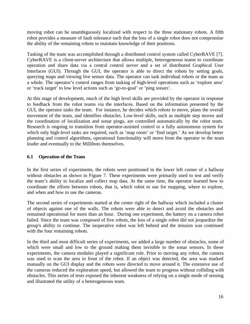
We have conducted a series of experiments to test the effectiveness of a team of Millibots toexplore and map a given area (Figure 6). Each series of runs was designed to slowly increase thecomplexity of operation to expose the strengths and weaknesses of the team. The task in eachmission was to explore and map as much area as possible before the team failed. Possible failuresincluded: loss of localization, loss of battery power or loss of communications. As an added utility,each series of runs was performed in different sections of the hallway. By merging maps from theseindividual runs, we were able to construct a composite map that represented the entire area

15
(Figure 7). The operator was positioned away from the experiments and could only receiveinformation about the environment via the team by viewing video from the robot cameras andobserving sensor information.
For each experiment, the team was composed of five Millibots. Three of the Millibots wereequipped with sonar arrays for collecting map information while the remaining two were equippedwith camera modules to aid in obstacle identification and provide a level of fault tolerance. Inaddition, each robot also housed a localization module that allowed them all to participate inlocalization. This heterogeneous makeup mixed the utility of sonar for extended range mappingwith the utility of high bandwidth cameras. A homogenous team of either type would have provedill prepared for the tasks. A team of camera robots could not produce effective range maps while ateam of sonar robots would be unable to detect certain types of obstacles.
Five robots were chosen to provide a degree of fault tolerance. Under a few initializationassumptions, three robots are sufficient to achieve and maintain localization. With four robots, one
Figure 7: Merging Maps
16
moving robot can be unambiguously localized with respect to the three stationary robots. A fifthrobot provides a measure of fault tolerance such that the loss of a single robot does not compromisethe ability of the remaining robots to maintain knowledge of their positions.
Tasking of the team was accomplished through a distributed control system called CyberRAVE [7].CyberRAVE is a client-server architecture that allows multiple, heterogeneous teams to coordinateoperation and share data via a central control server and a set of distributed Graphical UserInterfaces (GUI). Through the GUI, the operator is able to direct the robots by setting goals,querying maps and viewing live sensor data. The operator can task individual robots or the team asa whole. The operator’s control ranges from tasking of high-level operations such as ‘explore area’or ‘track target’ to low level actions such as ‘go-to-goal’ or ‘ping sonars’.
At this stage of development, much of the high level skills are provided by the operator in responseto feedback from the robot teams via the interfaces. Based on the information presented by theGUI, the operator tasks the team. For instance, he decides which robots to move, plans the overallmovement of the team, and identifies obstacles. Low-level skills, such as multiple step moves andthe coordination of localization and sonar pings, are controlled automatically by the robot team.Research is ongoing to transition from operator-assisted control to a fully autonomous system forwhich only high-level tasks are required, such as ‘map room’ or ‘find target.’ As we develop betterplanning and control algorithms, operational functionality will move from the operator to the teamleader and eventually to the Millibots themselves.
6.1 Operation of the Team
In the first series of experiments, the robots were positioned in the lower left corner of a hallwaywithout obstacles as shown in Figure 7. These experiments were primarily used to test and verifythe team’s ability to localize and collect map data. At the same time, the operator learned how tocoordinate the efforts between robots, that is, which robot to use for mapping, where to explore,and when and how to use the cameras.
The second series of experiments started at the center right of the hallway which included a clusterof objects against one of the walls. The robots were able to detect and avoid the obstacles andremained operational for more than an hour. During one experiment, the battery on a camera robotfailed. Since the team was composed of five robots, the loss of a single robot did not jeopardize thegroup's ability to continue. The inoperative robot was left behind and the mission was continuedwith the four remaining robots.
In the third and most difficult series of experiments, we added a large number of obstacles, some ofwhich were small and low to the ground making them invisible to the sonar sensors. In theseexperiments, the camera modules played a significant role. Prior to moving any robot, the camerawas used to scan the area in front of the robot. If an object was detected, the area was markedmanually on the GUI display and the robots were directed to move around it. The extensive use ofthe cameras reduced the exploration speed, but allowed the team to progress without colliding withobstacles. This series of tests exposed the inherent weakness of relying on a single mode of sensingand illustrated the utility of a heterogeneous team.

17
The last experiments were conducted in the top right of the hallway. These tests focused on howmuch area the robot team can map in a fixed amount of time. At this point the exploration rate isrelatively small, because a significant amount of time is needed for the human to react to sensorfeedback and make decisions. We expect the exploration rate of the robot team to increasesignificantly when more low-level tasks are handled by the team rather than the human operator.
6.2 Metrics
To evaluate and compare the performance of the team, we have developed a set of metrics. Well-defined metrics allow comparison between Millibot teams with different compositions, teams usingdifferent algorithms, as well as other robots and teams of robots.
Figure 8 lists the metrics obtained for the four runs described above. The first three columns reportthe logistical measures including the number sensing and acting commands. The last four columnsrepresent the performance metrics.
The column labeled “# Vector Cmds” lists the number of motion commands given to the teamduring a run. Each motion command corresponds to a vector with a relative angle and distance. Therobot first turns over the specified angle and then moves forward over the commanded distance.The next two columns report the number of distance measurement pairs and the number of sonarreadings taken by the team. After each motion command, the team performs distance measurementsusing the beacon sensors to update the robot position estimates. To improve sensing reliability,both distance measurements and sonar reading are the filtered result of eight separatemeasurements.
The performance of the robot team is characterized by the duration to perform a mission, the areaexplored per unit of time (coverage rate), the dimensional accuracy, and the power consumption.The dimensional accuracy is obtained by comparing the distance between mapped features (e.g.,two walls) with the actual distance. The energy consumption is measured by comparing the batterycharge for each robot before and after the experiment. An electronic battery monitor allows us tomeasure the remaining battery charge accurately.
The metrics reflect the difficulties encountered in the experiments. For example, the third run (witha large number of obstacles) required the extensive use of the camera. This resulted in a reducedcoverage rate and larger power consumption. The final experiments also resulted in larger powerconsumption, because the robots spent relatively more time moving around, which is very energy
# VectorCmds
# DistanceMeas (x 8)
# SonarPings (x 8)
Duration CoverageRate
Dim.Accuracy
PowerCon-sumption
run1 63 303 63 30 min 3.2 m2/hour 2.5 % 3.2 Wrun2 92 496 96 63 min 1.9 m2/hour 2.5 % 3.2 Wrun3 90 485 465 76 min 1.2 m2/hour * 3.4 Wrun4 86 431 450 30 min 3.3 m2/hour 1.6 % 3.8 W
Total 331 1715 1074 199 min
Figure 8: Experiment data

18
intensive. The dimensional accuracy reflects a combination of sonar accuracy and localizationaccuracy. A deviation of less than 3% in the distance measurement between two walls of themapped hallway is surprisingly good for team of robot of this size.
7 Summary
In this article, we have presented the design of a distributed robotic system consisting of very smallmobile robots called Millibots. Although the Millibots are small, they still contain a full set ofintegrated capabilities including sensing, computation, communication, localization, and mobility.To expand the capabilities even further, the Millibots have been designed in a modular fashionallowing one to easily create specialized robots with particular sensing configurations. Bycombining several such specialized robots, one can create a team with a very broad range ofcapabilities while still maintaining a small form factor.
An important component of the Millibots is a novel ultrasound-based localization system. Thissystem has the important advantage over currently existing systems that it does not require anyfixed beacons. By using the Millibots alternately as beacons and as localization receivers, the teamas a whole can reposition while maintaining accurate localization estimates at all times.
Tracking robot positions accurately is especially important for the mapping and explorationapplication that we have implemented. Each robot explores an unknown environment with its sonarand IR sensors. A team leader collects all the sensor information and integrates it into a global viewof the environment. The team leader uses an occupancy grid representation with a Bayesian updateto fuse the sensor data over time to build a composite map of the area.
Acknowledgements
The authors would like to thank all the current and past members of the CyberScout team for theircontributions, specifically, Curt Bererton, Pete Boettcher, Ethan Bold, Ben Brown, George Chow,Elliot Delaye, Brian Dougherty, Francine Gemperle, Dave Harden, Chris Inacio, Tony Nolla, andRebecca Schreiber.
This research is funded in part by the by the Distributed Robotics program of DARPA/ETO undercontract DABT63-97-1-0003, and by the Institute for Complex Engineered Systems at CarnegieMellon University. L.E. Navarro-Serment was supported by CONACyT and ITESM CampusGuadalajara.
References
[1] Arkin, R.C. and Balch, T.R. 1998. Cooperative Multiagent Robotic Systems AI-based MobileRobots: Case Studies of Successful Robot Systems. Kortenkamp, D., Bonasso, R.P. andMurphy, R. (eds). MIT Press.
[2] Atiya, S. and Hager, G. 1993. Real-time Vision-based Robot Localization. IEEE Transactions

19
on Robotics and Automation, Vol. 9, No. 6, pp. 785-800.
[3] Borenstein, J., Everett, H. R., and Feng, L., 1996. Navigating Mobile Robots: Sensors andTechniques, Wellesley, MA: A. K. Peters, Ltd.
[4] Brooks, R. A. 1986. A Robust Layered Control System for A Mobile Robot. IEEE Journal ofRobotics and Automation. Vol. RA-2. No. 1. March. pp 14-23.
[5] Conticelli, F., and Khosla, P.K. 1999. Image-Based Visual Control of NonholonomicMobileRobots. Technical Report, ICES04-05-99. The Institute for Complex EngineeredSystems. Carnegie Mellon University. Pittsburgh, PA 15213.
[6] Diehl, P.D, Saptharishi, M., Hampshire, J.B., and Khosla, P.K. 1999. CollaborativeSurveillance Using Both Fixed and Mobile Unattended Ground Sensor Platforms. SPIE's 13thAnnual International Symposium on Aerospace/Defense Sensing, Simulation, and Controls(AeroSense), 5–9 April, Marriott's Orlando World Center, Orlando, Florida USA.
[7] Dixon, K., Dolan, J., Huang, W., Paredis, C., Khosla, P., "RAVE: A Real and VirtualEnvironment for Multiple Mobile Robot Systems," in Proceedings of the IEEE/RSJInternational Conference on Intelligent Robots and Systems (IROS'99), Kyongju, Korea,October 17-21, 1999.
[8] Dixon, Kevin R., Theodore Q. Pham, and Pradeep K. Khosla, “Port-Based Adaptable AgentArchitecture”, to appear in Proceedings of the International Workshop on Self-adaptiveSoftware, 2000.
[9] Dolan, J. M., Trebi-Ollennu, A., Soto, A., and Khosla, P. K, 1999. Distributed TacticalSurveillance with ATVs. SPIE's 13th Annual International Symposium on Aerospace/DefenseSensing, Simulation, and Controls (AeroSense), 5–9 April, Marriott's Orlando World Center,Orlando, Florida USA.
[10] Elfes, A. 1989. Occupancy Grids: A Probabilistic Framework for Mobile robot Perception andnavigation. Ph.D. Thesis. Department of electrical and computer engineering. Carnegie MellonUniversity.
[11] Fletcher, R. 1987, Practical methods of optimization (second edition). New York, NJ: J. Wiley& Sons, Ltd.
[12] Getting, I. A. 1993. The Global Positioning System. IEEE Spectrum, December, pp. 36-47.
[13] Hollis, R. 1996. Whither Microbots? Proc. 7th. Int’l. Conf. On Micromachine and HumanScience (MHS ’96). Nagoya, Japan. October 2-5.
[14] ISR - IS Robotics, Inc., 1994. “RR-1/BS-1 System for Communications and Positioning -Preliminary Data Sheet.” IS Robotics, Twin City Office Center, Suite 6, 22 McGrath Highway,Somerville, MA 02143, 617-629-0055.
[15] Jenkin, M., Milios, E., Jasiobedzki, P., Bains, N., and Tran, K. 1993. Global Navigation for

20
ARK. Proceedings of the 1993 IEEE/RSJ International Conference on Intelligent Robotics andSystems. Yokohama, Japan, July 26-30, pp. 2165-2171.
[16] Kleeman, L. 1992. (May, Nice, France) Optimal estimation of Position and Heading forMobile Robots Using Ultrasonic Beacons and Dead-reckoning. Proceedings of the 1992 IEEEInternational Conference on Robotics and Automation. pp.2582-2587.
[17] Lekei, D., 1997. "Using a PIC16C5X as a Smart I2C Peripheral", AN541, MicrochipTechnology, Inc. Chandler, AZ.
[18] Leonard, J. F. and Durrant-Whyte, H. F., 1991. Mobile Robot Localization by TrackingGeometric Beacons. IEEE Transactions on Robotics and Automation. Vol. 7. No. 3. pp. 376-382.
[19] Mataric, M. 1995. Issues and Approaches in the Design of Collective Autonomous Agents.Robotics and Autonomous Systems, 16(2-4), Dec. 1995. pp. 321-331.
[20] McLurkin, J.D. Using Cooperative Robots for Explosive Ordnance Disposal. TechnicalDocument. Massachusetts Institute of Technology. Artificial Intelligence Laboratory.Cambridge, MA USA 02139.
[21] Mondada, F., Franzi, E., and Ienne, P. 1993. Mobile Robot Miniaturization: a Tool forInvestigation in Control Algorithms. ISER'93, Kyoto, Japan, October 1993.
[22] Moravec, H. P., "Sensor fusion in evidence grids for mobile robots," AI Magazine, pp 61-74,1988.
[23] Navarro-Serment, L.E, Paredis, C.J.J., and Khosla, P.K. 1999. "A Beacon System for theLocalization of Distributed Robotic Teams," In Proceedings of the International Conferenceon Field and Service Robotics, Pittsburgh, PA, August 29-31, 1999.
[24] Parker, L.E. 1999. Adaptive Heterogeneous Multi-Robot Teams, Neurocomputing, specialissue of NEURAP '98: Neural Networks and Their Applications 1999, vol. 28, pp. 75-92.
[25] Rus, D., Donald, B.R., and Jennings, J. 1995. Moving Furniture with Teams of AutonomousMobile Robots, in Proc. IEEE/Robotics Society of Japan International Workshop on IntelligentRobots and Systems, (IROS). Pittsburgh, PA.
[26] Salido, J., Paredis, C. J. J., and Khosla, P. K. 1999. Continuous Probabilistic Mapping byAutonomous Robots. To appear in Proceedings of the International Symposium onExperimental Robotics.
[27] Stuck, E. R., Manz, A., Green, D. A., and Elgazzar, S., 1994. Map Updating and Path Planningfor Real-Time Mobile Robot Navigation. 1994 International Conference on Intelligent Robotsand Systems (IROS '94). Munich, Germany, Sept. 12-16, pp. 753-760.
[28] Thrun, S. 1997. Learning Maps for Indoor Mobile Robot Navigation. AI Magazine.

21
[29] Veloso, M., Stone, P., Han, K. and Achim, S. 1998. The CMUnited-97 Small Robot Team. InProceedings of RoboCup-97: The First Robot World Cup Soccer Games and Conferences,Kitano, H. (ed.). Springer Verlag, Berlin.