herramientas de mecanizado vargus
TRANSCRIPT

Turning and Milling Tools
INC
H
Main CatalogThreading Grooving Boring
A d v a n c e d T h r e a d i n g S o l u t i o n s
INCH
TT GEN and TM GEN Thread Turning and Thread Milling Software for Tool Selection & CNC Program GeneratorThe latest version can be downloaded fromwww.vargususa.com
Ad
va
nc
ed
Th
re
ad
ing
So
luti
on
s
Tavl
it De
sign
Grou
p Lt
d.
221 - 00999INCH EE7 / 2 0 1 0EDITION 01
Tel: +1-800-828-8765 +1-608-756-4930Fax: +1-608-741-7125
Vargus USA 1149 Barberry DriveJanesville, WI 53545 U.S.A
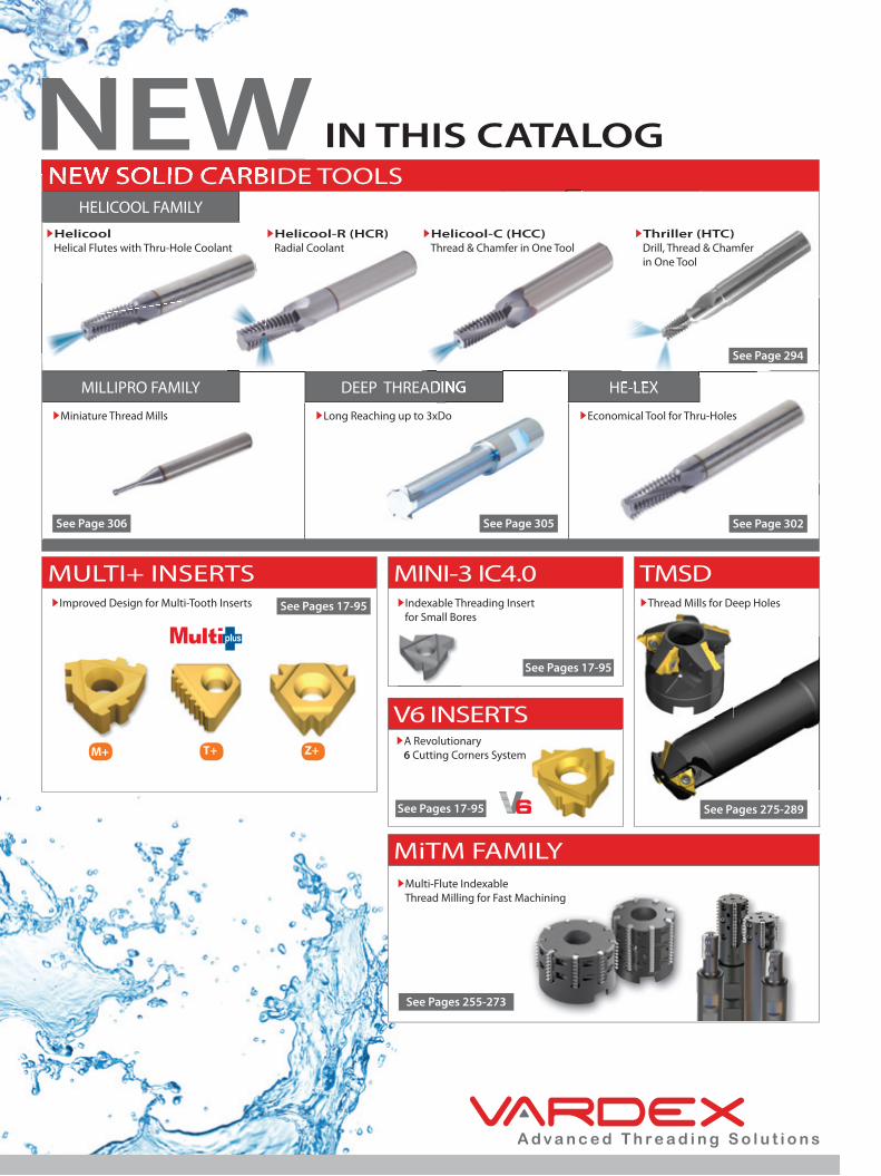
NEW SOLID CARBIDE TOOLSHELICOOL FAMILY
MILLIPRO FAMILY DEEP THREADING HE-LEX
NEW SOLID CARBIDE TOOLSNEW IN THIS CATALOG
MULTI+ INSERTS MINI-3 IC4.0 TMSD
V6 INSERTS
MiTM FAMILY
DEEP THREADING HE-LEX
Helicool Helical Flutes with Thru-Hole Coolant
Helicool-R (HCR) Radial Coolant
Helicool-C (HCC) Thread & Chamfer in One Tool
Thriller (HTC) Drill, Thread & Chamfer in One Tool
A Revolutionary 6 Cutting Corners System
Indexable Threading Insert for Small Bores
Multi-Flute Indexable Thread Milling for Fast Machining
For the complete list of VARDEX worldwide distributors, visit our website at www.vargususa.com
Thread Mills for Deep HolesImproved Design for Multi-Tooth Inserts
Miniature Thread Mills Long Reaching up to 3xDo Economical Tool for Thru-Holes
See Page 294
See Page 302See Page 305See Page 306
See Pages 17-95
See Pages 17-95
See Pages 17-95
See Pages 255-273
See Pages 275-289
M+ T+ Z+
A d v a n c e d T h r e a d i n g S o l u t i o n s
V A R D E X W O R L D W I D E
ChinaVargus China
Neumo-Vargus (Shanghai) Trading Co. Ltd. +86 215239 5005/6/9 [email protected]
DenmarkVargus Denmark
Damstahl Tooling A/S +45 8794 4100 [email protected]
France Vargus France +33 1 4601 7060 [email protected]
Germany Vargus Germany +49 7043 36 161 [email protected]
India Vargus India +91 98990 73393 [email protected]
IsraelVargus Israel
Neumo-Vargus Marketing Ltd +972 3 537 3275 [email protected]
PolandVargus Poland
Neumo-Polska Sp. Z.O.O.
+48 46 834 9904
+48 603 888 [email protected]
SwitzerlandVargus Switzerland
Werkzeugtechnik (Snel AG) +41 41784 2121 [email protected]
United Kingdom Vargus Tooling UK Ltd. +1 44 1952 583 222 [email protected]
USAVargus USA
Vardex USA
+1 800 828 8765
+608 756 [email protected]
Vargus Ltd. Headquarters +972 4 9855101 [email protected]
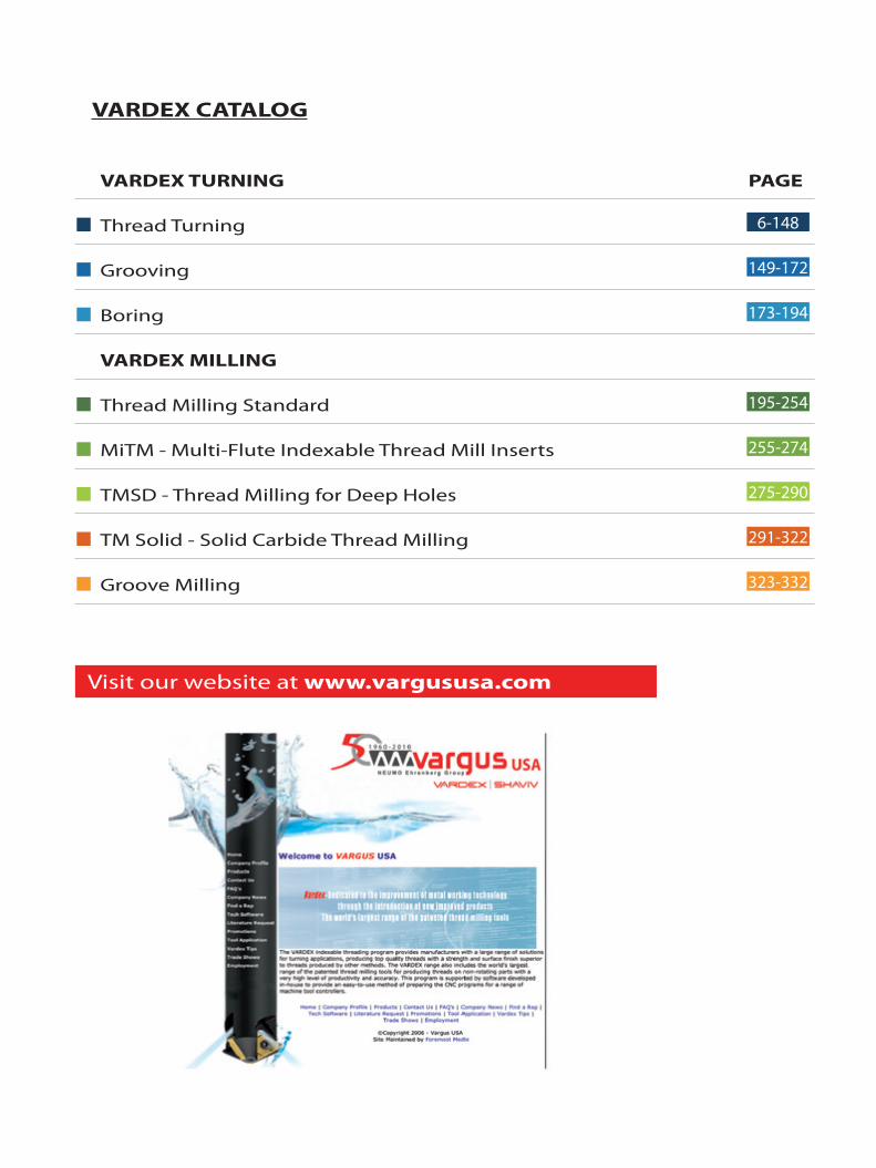
VARDEX CATALOG
VARDEX TURNING PAGE
Thread Turning 6-148
Grooving 149-172
Boring 173-194
VARDEX MILLING
Thread Milling Standard 195-254
MiTM - Multi-Flute Indexable Thread Mill Inserts 255-274
TMSD - Thread Milling for Deep Holes 275-290
TM Solid - Solid Carbide Thread Milling 291-322
Groove Milling 323-332
Visit our website at www.vargususa.com

N U M B E R O N E I N T H R E A D I N GVARGUS is a world leading developer, manufacturer and supplier of high-quality, precision cutting
and deburring tools. The company’s VARDEX product line is the number one source for threading
solutions worldwide and includes the largest range of thread turning and thread milling solutions
as well as an extensive range of solutions for micro-machining.
Established in 1960, VARGUS is a member of the NEUMO Ehrenberg Group, a diversified multi-national
organization headquartered in Knittlingen, Germany. With a network of international distributors,
warehouses and certified ISO 9001 manufacturing facilities, VARGUS serves customers in more than
100 countries around the globe, providing fast delivery and dedicated customer service.
Vargus is a customer-focused organization, committed to providing innovative products of the
highest quality, excellent value, top service and technical expertise.
These key values have helped Vargus remain the market leader in threading solutions and will
continue to guide our approach to business in the future.

V A R D E X S P E C I A L T O O L S
Tai lor M ade
VARDEX engineers and toolmakers have the know-how and experience to design special cutting tools tailored
to customer requirements. Whether it’s a special, complex shape or a non-standard size, our Special Tools
service can quickly produce the tool you need using the latest techniques and technology.
For specific details, contact your nearest VARDEX sales representative.
VARDEX expertise Fast quotation Competitive delivery

Thread Turning System - External ............................................................................................................................... Page 6
Tooling Recommendation .............................................................................................................................................. Page 8
Threading
Threading Inserts .................................................................................................................................................................. Page 17
Threading Toolholders ....................................................................................................................................................... Page 97
Threading Technical Data ................................................................................................................................................ Page 121
Grooving
Grooving Inserts .................................................................................................................................................................... Page 149
Grooving Toolholders ......................................................................................................................................................... Page 165
Grooving Technical Data .................................................................................................................................................. Page 171
Boring
Boring Inserts........................................................................................................................................................................... Page 173
Boring Toolholders ............................................................................................................................................................... Page 183
Boring Technical Data ........................................................................................................................................................ Page 191
TT Gen: Takes the guesswork out of threading!
TURNING
TT Gen Thread Turning Tool Selection SoftwareVARGUS’ TT Gen software guides you to the right thread turning tool and the best cutting conditions for your applications in seconds.
The latest version can be downloaded at www.vargususa.com
(Compatible with W
indows 95 and U
p, Wind
ows N
T)

> Threading
> Grooving
> Boring
Turning
6
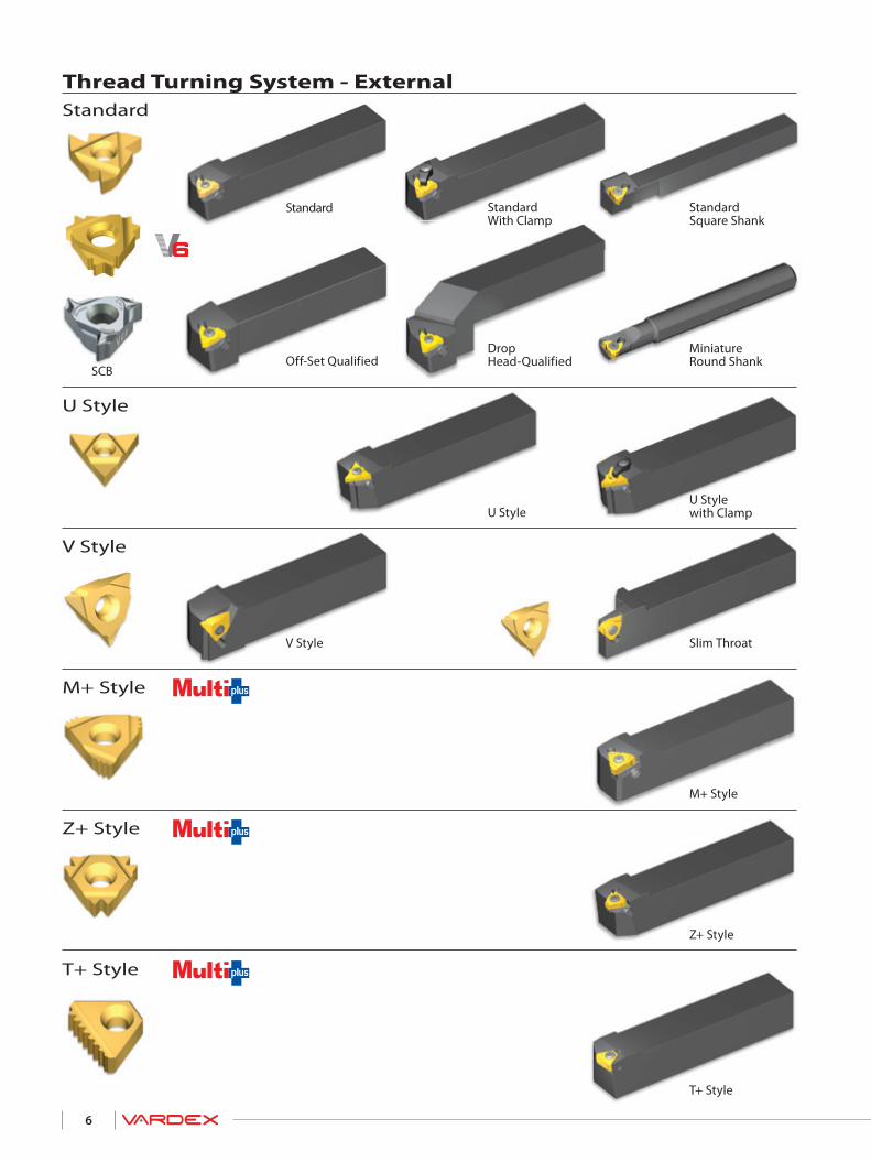
Thread Turning System - ExternalStandard
U Style
V Style
M+ Style
Z+ Style
T+ Style
Standard
Off-Set QualifiedSCB
StandardWith Clamp
Drop Head-Qualified
StandardSquare Shank
Miniature Round Shank
U Style with Clamp
Slim Throat
M+ Style
Z+ Style
T+ Style
V Style
U Style
7
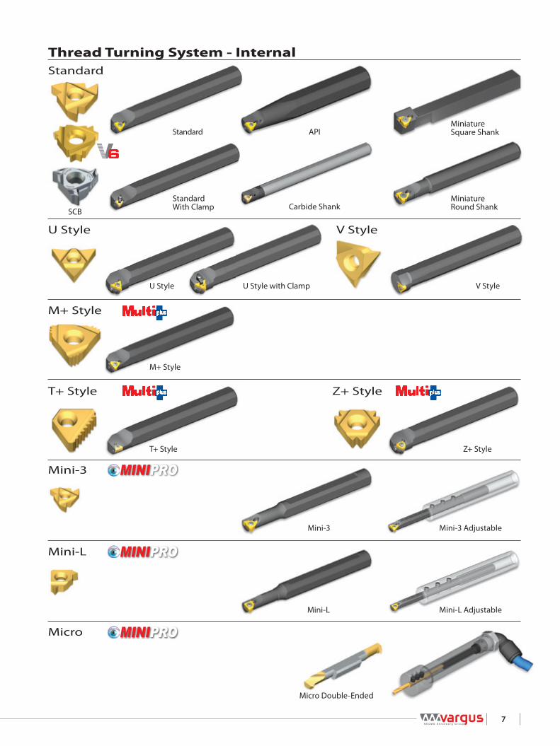
Thread Turning System - InternalStandard
U Style V Style
Z+ Style
Mini-3
M+ Style
T+ Style
Mini-L
Micro
SCB
Standard API
StandardWith Clamp Carbide Shank
Miniature Square Shank
Miniature Round Shank
U Style with ClampU Style
M+ Style
T+ Style
Mini-3
Mini-L
Micro Double-Ended
Mini-L Adjustable
Mini-3 Adjustable
Z+ Style
V Style

8
American UNPitch tpi Thread Insert Size Ordering Code
Insert Holder Anvil
56 10 - 1/4 Micro 4.0 Special SMC..-4.0 -48 10 - 5/16 Micro 4.0 Special SMC..-4.0 -40 10 - 3/8 Micro 4.0 4.0SIR40UN SMC..-4.0 -36 12 - 3/8 Micro 4.0 4.0SIR36UN SMC..-4.0 -
32
12 - 1/4 Micro 4.0 4.0SIR32UN SMC..-4.0 -5/16 - 3/8 Micro 6.0 6.0SIR32UN SMC..-6.0 -7/16 - 1/2 IC 6.0 6.0IR32UN NVR...-6.0 -9/16 - 11/16 IC 1/4” 2IR32UN NVR0375-2 -3/4 - 15/16 IC 3/8”” 3IR32UN NVR050-3 -7/8 - 15/16 IC 3/8” 3IR32UN NVR0625-3 -1 IC 3/8” 3IR32UN AVR075-3 YI3 - 1N
28
12 - 1/4 Micro 4.0 4.0SIR28UN SMC..-4.0 -5/16 - 3/8 Micro 6.0 6.0SIR28UN SMC..-6.0 -7/16 - 1/2 IC 6.0 6.0IR28UN NVR...-6.0 -5/8 - 11/16 IC 1/4” 2IR28UN NVR0375-2 -3/4 - 13/16 IC 3/8” 3IR28UN NVR050-3 -7/8 - 15/16 IC 3/8” 3IR28UN NVR0625-3 -1 - 1 1/8 IC 3/8” 3IR28UN AVR075-3 YI3 - 1N1 3/16 IC 3/8” 3IR28UN AVR100-3 YI3 - 1N
27
1/4 Micro 4.0 4.0SIR27UN SMC..-4.0 -5/16 - 3/8 Micro 6.0 6.0SIR27UN SMC..-6.0 -7/16 - 1/2 IC 6.0 Special NVR...-6.0 -9/16 - 5/8 IC 1/4” 2IR27UN NVR0375-2 -3/4 IC 3/8” 3IR27UN NVR050-3 -7/8 IC 3/8” 3IR27UN NVR0625-3 -1 IC 3/8” 3IR27UN AVR075-3 YI3 - 1N
24
12 - 1/4 Micro 4.0 4.0SIR24UN SMC..-4.0 -5/16 - 3/8 Micro 6.0 6.0SIR24UN SMC..-6.0 -7/16 IC 5.0 L 5LIR24UN NVR0375-5L -1/2 IC 6.0 6.0IR24UN NVR...-6.0 -9/16 - 11/16 IC 1/4” 2IR24UN NVR0375-2 -3/4 IC 3/8” 3IR24UN NVR050-3 -7/8 IC 3/8” 3IR24UN NVR0625-3 -1 - 1 1/8 IC 3/8” 3IR24UN AVR075-3 YI3 - 1N1 1/4 - 1 1/2 IC 3/8” 3IR24UN AVR100-3 YI3 - 1N1 5/8 - 24 IC 3/8” 3IR24UN AVR125-3 YI3 - 1N
20
5/16 - 3/8 Micro 6.0 6.0SIR20UN SMC..-6.0 -7/16 IC 5.0 L 5LIR20UN NVR0375-5L -1/2 - 9/16 IC 6.0 6.0IR20UN NVR...-6.0 -5/8 - 11/16 IC 1/4” 2IR20UN NVR0375-2 -3/4 - 13/16 IC 3/8” 3IR20UN NVR050-3 -7/8 - 15/16 IC 3/8” 3IR20UN NVR0625-3 -1 - 1 3/16 IC 3/8” 3IR20UN AVR075-3 YI3 - 1N1 1/4 - 1 1/2 IC 3/8” 3IR20UN AVR100-3 YI3 - 1N1 9/16 - 1 13/16 IC 3/8” 3IR20UN AVR125-3 YI3 - 1N1 7/8 - 2 1/8 IC 3/8” 3IR20UN AVR150-3 YI3 - 1N
TT Gen Software
and updated versions
can be downloaded from
www.vargususa.comTooling recommendation for a given Internal thread specification

9
American UN (con't)Pitch tpi Thread Insert Size Ordering Code
Insert Holder Anvil
18
5/16 - 3/8 Micro 6.0 6.0SIR18UN SMC..-6.0 -7/16 IC 5.0 L 5LIR18UN NVR0375-5L -1/2 - 9/16 IC 6.0 6.0IR18UN NVR...-6.0 -5/8 IC 1/4” 2IR18UN NVR0375-2 -3/4 IC 3/8” 3IR18UN NVR050-3 -7/8 - 1 IC 3/8” 3IR18UN NVR0625-3 -1 1/16 - 1 3/16 IC 3/8” 3IR18UN AVR075-3 YI3 - 1N1 1/4 - 1 1/2 IC 3/8” 3IR18UN AVR100-3 YI3 - 1N1 9/16 - 1 3/4 IC 3/8” 3IR18UN AVR125-3 YI3 - 1N1 7/8 - 2 IC 3/8” 3IR18UN AVR150-3 YI3 - 1N
16
3/8 Micro 6.0 6.0SIR16UN SMC..-6.0 -7/16 IC 5.0 L 5LIR16UN NVR0375-5L -1/2 - 9/16 IC 6.0 6.0IR16UN NVR...-6.0 -5/8 - 11/16 IC 1/4” 2IR16UN NVR0375-2 -3/4 - 13/16 IC 3/8” 3IR16UN NVR050-3 -7/8 - 1 IC 3/8” 3IR16UN NVR0625-3 -1 1/16 - 1 1/8 IC 3/8” 3IR16UN AVR075-3 YI31 3/16 IC 3/8” 3IR16UN AVR075-3 YI3 - 1N1 1/4 - 1 1/2 IC 3/8” 3IR16UN AVR100-3 YI3 - 1N1 9/16 - 1 13/16 IC 3/8” 3IR16UN AVR125-3 YI3 - 1N1 7/8 - 2 1/8 IC 3/8” 3IR16UN AVR150-3 YI3 - 1N
14
7/16 IC 5.0 L 5LIR14UN NVR0375-5L -1/2 - 9/16 IC 6.0 6.0IR14UN NVR...-6.0 -5/8 IC 1/4” 2IR14UN NVR0375-2 -3/4 IC 3/8” 3IR14UN NVR050-3 -7/8 - 1 IC 3/8” 3IR14UN NVR0625-3 -1 1/8 IC 3/8” 3IR14UN AVR075-3 YI31 1/4 IC 3/8” 3IR14UN AVR100-3 YI31 3/8 - 1 1/2 IC 3/8” 3IR14UN AVR100-3 YI3 - 1N1 5/8 - 1 3/4 IC 3/8” 3IR14UN AVR125-3 YI3 - 1N1 7/8 - 2 IC 3/8” 3IR14UN AVR150-3 YI3 - 1N
13 1/2 - 13 IC 6.0 6.0I13UN...158/001 BNVR050S-6.0 -
12
9/16 - 11/16 IC 1/4” 2I12UN...158/002 NVRC040-2 157/001 -3/4 - 7/8 IC 3/8” 3IR12UN NVR050-3 -15/16 - 1 IC 3/8” 3IR12UN NVR0625-3 -1 1/16 - 1 3/16 IC 3/8” 3IR12UN AVR075-3 YI31 1/4 - 1 1/2 IC 3/8” 3IR12UN AVR100-3 YI31 9/16 - 1 13/16 IC 3/8” 3IR12UN AVR125-3 YI31 7/8 - 2 1/8 IC 3/8” 3IR12UN AVR150-3 YI3 - 1N
11 5/8 - 11 IC 1/4U” 2UIR11UN...158/003 NVRC044-2U 157/002 -
10
7/8 IC 3/8” 3IR10UN NVR050-3 -1 - 10 IC 3/8” 3IR10UN NVR0625-3 -1 1/8 - 10 IC 3/8” 3IR10UN AVR075-3 YI31 1/4 - 1 1/2 IC 3/8” 3IR10UN AVR100-3 YI31 5/8 - 1 3/4 IC 3/8” 3IR10UN AVR125-3 YI31 7/8 - 2 IC 3/8” 3IR10UN AVR150-3 YI3
TT Gen Software
and updated versions
can be downloaded from
www.vargususa.comTooling recommendation for a given Internal thread specification

10
American UN (con't)Pitch tpi Thread Insert Size Ordering Code
Insert Holder Anvil
9 7/8 - 9 IC 3/8” 3IR9UN NVR050-3 -
8
1 IC 3/8” 3IR8UN NVR0625-3 -1 1/16 - 1 3/16 IC 3/8” 3IR8UN AVR075-3 YI3 - 1P1 1/4 IC 3/8” 3IR8UN AVR075-3 YI31 5/16 - 1 1/2 IC 3/8” 3IR8UN AVR100-3 YI31 9/16 - 1 13/16 IC 3/8” 3IR8UN AVR125-3 YI31 7/8 - 2 1/8 IC 3/8” 3IR8UN AVR150-3 YI3
7 1 1/8 - 1 1/4 IC 1/2” 4IR7UN NVR075-4 -
6
1 3/8 - 1 7/16 IC 1/2” 4IR6UN NVR075-4 -1 1/2 - 1 5/8 IC 1/2” 4IR6UN AVR100-4 YI4 - 1P1 11/16 IC 1/2” 4IR6UN AVR100-4 YI41 3/4 - 2 IC 1/2” 4IR6UN AVR125-4 YI42 1/8 - 6 IC 1/2” 4IR6UN AVR150-4 YI4
5 1 3/4 - 5 IC 1/2” 4IR5UN AVR100-4 YI4 - 1P4.5 2 - 4 1/2 IC 5/8” 5IR4.5UN AVR125-5 YI5 - 1P
TT Gen Software
and updated versions
can be downloaded from
www.vargususa.comTooling recommendation for a given Internal thread specification
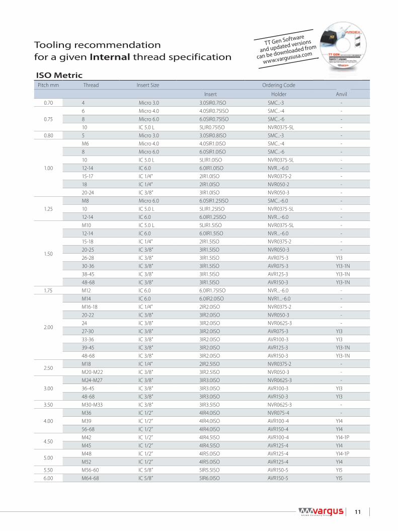
11
ISO MetricPitch mm Thread Insert Size Ordering Code
Insert Holder Anvil
0.70 4 Micro 3.0 3.0SIR0.7ISO SMC..-3 -
0.756 Micro 4.0 4.0SIR0.75ISO SMC..-4 -8 Micro 6.0 6.0SIR0.75ISO SMC..-6 -10 IC 5.0 L 5LIR0.75ISO NVR0375-5L -
0.80 5 Micro 3.0 3.0SIR0.8ISO SMC..-3 -
1.00
M6 Micro 4.0 4.0SIR1.0ISO SMC..-4 -8 Micro 6.0 6.0SIR1.0ISO SMC..-6 -10 IC 5.0 L 5LIR1.0ISO NVR0375-5L -12-14 IC 6.0 6.0IR1.0ISO NVR...-6.0 -15-17 IC 1/4” 2IR1.0ISO NVR0375-2 -18 IC 1/4” 2IR1.0ISO NVR050-2 -20-24 IC 3/8” 3IR1.0ISO NVR050-3 -
1.25M8 Micro 6.0 6.0SIR1.25ISO SMC..-6.0 -10 IC 5.0 L 5LIR1.25ISO NVR0375-5L -12-14 IC 6.0 6.0IR1.25ISO NVR...-6.0 -
1.50
M10 IC 5.0 L 5LIR1.5ISO NVR0375-5L -12-14 IC 6.0 6.0IR1.5ISO NVR...-6.0 -15-18 IC 1/4” 2IR1.5ISO NVR0375-2 -20-25 IC 3/8” 3IR1.5ISO NVR050-3 -26-28 IC 3/8” 3IR1.5ISO AVR075-3 YI330-36 IC 3/8” 3IR1.5ISO AVR075-3 YI3-1N38-45 IC 3/8” 3IR1.5ISO AVR125-3 YI3-1N48-68 IC 3/8” 3IR1.5ISO AVR150-3 YI3-1N
1.75 M12 IC 6.0 6.0IR1.75ISO NVR...-6.0 -
2.00
M14 IC 6.0 6.0IR2.0ISO NVR1...-6.0 -M16-18 IC 1/4” 2IR2.0ISO NVR0375-2 -20-22 IC 3/8” 3IR2.0ISO NVR050-3 -24 IC 3/8” 3IR2.0ISO NVR0625-3 -27-30 IC 3/8” 3IR2.0ISO AVR075-3 YI333-36 IC 3/8” 3IR2.0ISO AVR100-3 YI339-45 IC 3/8” 3IR2.0ISO AVR125-3 YI3-1N48-68 IC 3/8” 3IR2.0ISO AVR150-3 YI3-1N
2.50M18 IC 1/4” 2IR2.5ISO NVR0375-2 -M20-M22 IC 3/8” 3IR2.5ISO NVR050-3 -
3.00M24-M27 IC 3/8” 3IR3.0ISO NVR0625-3 -36-45 IC 3/8” 3IR3.0ISO AVR100-3 YI348-68 IC 3/8” 3IR3.0ISO AVR150-3 YI3
3.50 M30-M33 IC 3/8” 3IR3.5ISO NVR0625-3 -
4.00M36 IC 1/2” 4IR4.0ISO NVR075-4 -M39 IC 1/2” 4IR4.0ISO AVR100-4 YI456-68 IC 1/2” 4IR4.0ISO AVR150-4 YI4
4.50M42 IC 1/2” 4IR4.5ISO AVR100-4 YI4-1PM45 IC 1/2” 4IR4.5ISO AVR125-4 YI4
5.00M48 IC 1/2” 4IR5.0ISO AVR125-4 YI4-1PM52 IC 1/2” 4IR5.0ISO AVR125-4 YI4
5.50 M56-60 IC 5/8” 5IR5.5ISO AVR150-5 YI56.00 M64-68 IC 5/8” 5IR6.0ISO AVR150-5 YI5
TT Gen Software
and updated versions
can be downloaded from
www.vargususa.comTooling recommendation for a given Internal thread specification

12
WhitworthPitch tpi Thread Insert Size Ordering Code
Insert Holder Anvil
26
1/4 Micro 4.0 4.0SIR26W SMC..-4.0 -5/16 - 1/2 Micro 6.0 6.0SIR26W SMC..-6.0 -9/16 - 5/8 IC 1/4” 2IR26W NVR0375-2 -11/16 IC 1/4” 2IR26W NVR050-2 -3/4 - 13/16 IC 3/8” 3IR26W NVR050-3 -7/8 - 15/16 IC 3/8” 3IR26W NVR0625-3 -1 - 1 3/16 IC 3/8” 3IR26W AVR075-3 YI3 - 1N1 1/4 - 1 7/16 IC 3/8” 3IR26W AVR100-3 YI3 - 1N1 1/2 - 1 3/4 IC 3/8” 3IR26W AVR125-3 YI3 - 1N1 7/8 - 2 IC 3/8” 3IR26W AVR150-3 YI3 - 1N
22 5/16 Micro 6.0 6.0SIR22W SMC..-6.0 -
20
3/8 - 9/16 Micro 6.0 6.0SIR20W SMC..-6.0 -5/8 - 11/16 IC 1/4” 2IR20W NVR0375-2 -3/4 - 13/16 IC 3/8” 3IR20W NVR050-3 -7/8 - 1 IC 3/8” 3IR20W NVR0625-3 -1 1/16 - 1 3/16 IC 3/8” 3IR20W AVR075-3 YI3 - 1N1 1/4 - 1 7/16 IC 3/8” 3IR20W AVR100-3 YI3 - 1N1 1/2 - 1 3/4 IC 3/8” 3IR20W AVR125-3 YI3 - 1N1 7/8 - 3 IC 3/8” 3IR20W AVR150-3 YI3 - 1N11/16 IC 1/4” 2IR16W NVR0375-2 -3/4 - 11/16 IC 3/8” 3IR16W NVR050-3 -7/8 - 1 IC 3/8” 3IR16W NVR0625-3 -
16
1 1/16 - 1 1/8 IC 3/8” 3IR16W AVR075-3 YI31 3/16 IC 3/8” 3IR16W AVR075-3 YI3 - 1N1 1/4 - 1 7/16 IC 3/8” 3IR16W AVR100-3 YI3 - 1N1 1/2 - 1 3/4 IC 3/8” 3IR16W AVR125-3 YI3 - 1N1 7/8 - 4 5/8 IC 3/8” 3IR16W AVR150-3 YI3 - 1N4 3/4 - 7 IC 3/8” 3IR16W AVR150-3 YI3 - 1.5N
147/16 IC 5.0 L 5LIR14W NVR0375-5L -5/8 - 11/16 IC 1/4” 2IR14W NVR0375-2 -
12
13/16 IC 3/8” 3IR12W NVR050-3 -15/16 - 1 IC 3/8” 3IR12W NVR0625-3 -1 1/16 - 1 3/16 IC 3/8” 3IR12W AVR075-3 YI31 1/4 - 1 1/2 IC 3/8” 3IR12W AVR100-3 YI31.6 - 1 3/4 IC 3/8” 3IR12W AVR125-3 YI3 - 1N1 7/8 - 6 IC 3/8” 3IR12W AVR150-3 YI3 - 1N6 1/4 - 7 IC 3/8” 3IR12W AVR150-3 YI3 - 1.5N
11 7/8 IC 3/8” 3IR11W NVR050-3 -10 1 IC 3/8” 3IR10W NVR0625-3 -
TT Gen Software
and updated versions
can be downloaded from
www.vargususa.comTooling recommendation for a given Internal thread specification

13
Whitworth (con't)Pitch tpi Thread Insert Size Ordering Code Anvil
Insert Holder
97/8 IC 3/8” 3IR9W NVR050-3 -1 1/8 - 1 1/4 IC 3/8” 3IR9W AVR075-3 YI3
8
1 IC 3/8” 3IR8W NVR0625-3 -1 3/16 IC 3/8” 3IR8W AVR075-3 YI3 - 1P1 5/16 - 1 1/2 IC 3/8” 3IR8W AVR100-3 YI31.6 - 1 7/8 IC 3/8” 3IR8W AVR125-3 YI31.9 - 2 1/4 IC 3/8” 3IR8W AVR150-3 YI32.4 - 7 IC 3/8” 3IR8W AVR150-3 YI3 - 1N
71 1/4 IC 1/2” 4IR7W NVR075-4 -1 3/4 - 2 IC 1/2” 4IR7W AVR125-4 YI4
6
1 5/16 - 1 7/16 IC 1/2” 4IR6W NVR075-4 -1 1/2 - 1 5/8 IC 1/2” 4IR6W AVR100-4 YI4 - 1P1 7/8 - 1.9 IC 1/2” 4IR6W AVR125-4 YI42.1 - 3.1 IC 1/2” 4IR6W AVR150-4 YI43 1/4 - 7 IC 1/2” 4IR6W AVR150-4 YI4 - 1N
51 3/4 IC 1/2” 4IR5W AVR100-4 YI4 - 1P3 - 3 1/4 IC 1/2” 4IR5W AVR150-4 YI4
4.52 IC 5/8” 5IR4.5W AVR125-5 YI5 - 1P3 1/2 - 4 IC 5/8” 5IR4.5W AVR250-5 YI5
4
2 1/4 IC 5/8” 5IR4W AVR150-5 YI5 - 1P2 1/2 IC 5/8” 5IR4W AVR150-5 YI54 1/4 - 4 3/4 IC 5/8” 5IR4W AVR250-5 YI54 7/8 - 7 IC 5/8” 5IR4W AVR250-5 YI5 - 1N
3.52 3/4 IC 5/8” U 5UEI3.5W AVR150-5U YI5U - 1P3 IC 5/8” U 5UEI3.5W AVR200-5U YI5U
3.253 1/4 IC 5/8” U 5UEI3.25W AVR200-5U YI5U3 1/2 IC 5/8” U 5UEI3.25W AVR250-5U YI5U
3 3 3/4 - 4 IC 5/8” U 5UEI3W AVR250-5U YI5U2.75 5 IC 5/8” U 5UEI2.75W AVR250-5U YI5U2.5 6 IC 5/8” V 5VIR2.5W NVR250-5V -
TT Gen Software
and updated versions
can be downloaded from
www.vargususa.com
Anvil
Tooling recommendation for a given Internal thread specification

14
NPTPitch tpi Thread Insert Size Ordering Code
Insert Holder Anvil
27 1/16 Micro 6.0 6.0SIR27NPT SMC..-6.0 -
181/4 Micro 6.0 6.0SIR18NPT SMC..-6.0 -3/8 Micro 6.0 6.0SIR18NPT SMC..-6.0 -
141/2 IC 3/8" 3IR14NPT NVR050-3 -3/4 IC 3/8" 3IR14NPT NVR050-3 -
11.5
1 IC 3/8" 3IR11.5NPT AVR075-3 YI31 1/4 IC 3/8" 3IR11.5NPT AVR125-3 YI31 1/2 IC 3/8" 3IR11.5NPT AVR125-3 YI3 - 1N2 IC 3/8" 3IR11.5NPT AVR150-3 YI3 - 1N
8
2 1/2 IC 3/8" 3IR8NPT AVR150-3 YI3 - 1N3 IC 3/8" 3IR8NPT AVR150-3 YI3 - 1N3 1/2 IC 3/8" 3IR8NPT AVR150-3 YI3 - 1N4 IC 3/8" 3IR8NPT AVR150-3 YI3 - 1N5 IC 3/8" 3IR8NPT AVR150-3 YI3 - 1N6 IC 3/8" 3IR8NPT AVR150-3 YI3 - 1N8 IC 3/8" 3IR8NPT AVR150-3 YI3 - 1N10 IC 3/8" 3IR8NPT AVR150-3 YI3 - 1N12 IC 3/8" 3IR8NPT AVR150-3 YI3 - 1N
NPTFPitch tpi Thread Insert Size Ordering Code
Insert Holder Anvil
27 1/8 IC 5.0 L 5LIR27NPTF NVR...-5L -
181/4 IC 6.0 6.0IR18NPTF NVR1...-6.0 -3/8 IC 1/4" 2IR18NPTF NVR0375-2 -
141/2 IC 3/8" 3IR14NPTF NVR050-3 -3/4 IC 3/8" 3IR14NPTF NVR0625-3 -
11.5
1 IC 3/8" 3IR11.5NPTF AVR075-3 YI31 1/4 IC 3/8" 3IR11.5NPTF AVR125-3 YI31 1/2 IC 3/8" 3IR11.5NPTF AVR125-3 YI3 - 1N2 IC 3/8" 3IR11.5NPTF AVR150-3 YI3 - 1N
82 1/2 IC 3/8" 3IR8NPTF AVR150-3 YI3 - 1N3 IC 3/8" 3IR8NPTF AVR150-3 YI3 - 1N
PGPitch tpi Thread Insert Size Ordering Code
Insert Holder Anvil
20 Pg 7 IC 6.0 6.0IR20PG NVR...6.0 -
18Pg 9 IC 1/4" 2IR18PG NVR0375-2 -Pg 11 & Pg 13.5 IC 3/8" 3IR18PG NVR050-3 -Pg 16 IC 3/8" 3IR18PG NVR0625-3 -
16Pg 21 IC 3/8" 3IR16PG AVR075-3 YI3Pg 29 IC 3/8" 3IR16PG AVR100-3 YI3 - 1NPg 36 & Pg 42 & Pg 48 IC 3/8" 3IR16PG AVR150-3 YI3 - 1N
TT Gen Software
and updated versions
can be downloaded from
www.vargususa.comTooling recommendation for a given Internal thread specification

15
BSP (55°)Pitch tpi Thread Insert Size Ordering Code
Insert Holder Anvil
28G1/16 Micro 6.0 6.0SIR28W SMC..-6.0 -G1/8 IC 5.0 L 5LIR28W NVR0375-5L -
19G1/4 IC 6.0 6.0IR19W NVR ...-6.0 -G3/8 IC 1/4" 2IR19W NVR0375-2 -
14G1/2 & G5/8 IC 3/8" 3IR14W NVR050-3 -G3/4 & G7/8 IC 3/8" 3IR14W AVR075-3 YI3
11
G1 & G1 1/8 & 1 1/4 IC 3/8" 3IR11W AVR100-3 YI3G1 1/2 IC 3/8" 3IR11W AVR150-3 YI3 - 1NG1 3/4 IC 3/8" 3IR11W AVR150-3 YI3 - 1NG2 IC 3/8" 3IR11W AVR150-3 YI3 - 1NG2 1/4 IC 3/8" 3IR11W AVR150-3 YI3 - 1NG2 1/2 IC 3/8" 3IR11W AVR150-3 YI3 - 1NG2 3/4 IC 3/8" 3IR11W AVR150-3 YI3 - 1NG3 IC 3/8" 3IR11W AVR150-3 YI3 - 1NG3 1/2 IC 3/8" 3IR11W AVR150-3 YI3 - 1NG4 IC 3/8" 3IR11W AVR150-3 YI3 - 1NG4 1/2 IC 3/8" 3IR11W AVR150-3 YI3 - 1NG5 IC 3/8" 3IR11W AVR150-3 YI3 - 1NG5 1/2 IC 3/8" 3IR11W AVR150-3 YI3 - 1NG6 IC 3/8" 3IR11W AVR150-3 YI3 - 1N
BSPTPitch tpi Thread Insert Size Ordering Code
Insert Holder Anvil
28 1/8 IC 5.0 L 5LIR28BSPT NVR...-5L -
191/4 IC 6.0 6.0IR19BSPT NVR...-6.0 -3/8 IC 1/4" 2IR19BSPT NVR0375-2 -
141/2 IC 3/8" 3IR14BSPT NVR050-3 -3/4 IC 3/8" 3IR14BSPT AVR075-3 YI3
11
1 IC 3/8" 3IR11BSPT AVR100-3 YI31 1/4 IC 3/8" 3IR11BSPT AVR125-3 YI31 1/2 IC 3/8" 3IR11BSPT AVR150-3 YI3 - 1N2 IC 3/8" 3IR11BSPT AVR150-3 YI3 - 1N2 1/2 IC 3/8" 3IR11BSPT AVR150-3 YI3 - 1N3 IC 3/8" 3IR11BSPT AVR150-3 YI3 - 1N4 IC 3/8" 3IR11BSPT AVR150-3 YI3 - 1N5 IC 3/8" 3IR11BSPT AVR150-3 YI3 - 1N6 IC 3/8" 3IR11BSPT AVR150-3 YI3 - 1N
TT Gen Software
and updated versions
can be downloaded from
www.vargususa.comTooling recommendation for a given Internal thread specification

16
> Inserts
Thread Turning

18
Thre
ad T
urni
ng
Inse
rts
THREAD TURNING INSERTS
VARDEX Ordering Code System ..................................................................................................................................................Page 19
Partial Profile 60° ....................................................................................................................................................................................Page 20
Partial Profile 55° ....................................................................................................................................................................................Page 23
American UN ...........................................................................................................................................................................................Page 26
ISO Metric ..................................................................................................................................................................................................Page 36
Whitworth for BSW, BSP ...................................................................................................................................................................Page 45
BSPT ..............................................................................................................................................................................................................Page 53
NPT ................................................................................................................................................................................................................Page 56
NPTF .............................................................................................................................................................................................................Page 61
NPS ................................................................................................................................................................................................................Page 64
Round (DIN 405) ...................................................................................................................................................................................Page 65
Round (DIN 20400) ..............................................................................................................................................................................Page 66
Trapez ..........................................................................................................................................................................................................Page 67
American ACME ....................................................................................................................................................................................Page 70
Stub ACME................................................................................................................................................................................................Page 73
UNJ ................................................................................................................................................................................................................Page 76
MJ ...................................................................................................................................................................................................................Page 81
American Buttress ................................................................................................................................................................................Page 83
British Buttress ........................................................................................................................................................................................Page 85
Metric Buttress (Sägengewinde) ................................................................................................................................................Page 86
API ... . . . . . . . . . . . . . . . . . . . . . . . . . . . . . . . . . . . . . . . . . . . . . . . . . . . . . . . . . . . . . . . . . . . . . . . . . . . . . . . . . . . . . . . . . . . . . . . . . . . . . . . . . . . . . . . . . . . . . . . . . . . . . . . . . . . . . . . . . . . . . . . . . . . . . . . . . . . .Page 87
API Buttress Casing .... . . . . . . . . . . . . . . . . . . . . . . . . . . . . . . . . . . . . . . . . . . . . . . . . . . . . . . . . . . . . . . . . . . . . . . . . . . . . . . . . . . . . . . . . . . . . . . . . . . . . . . . . . . . . . . . . . . . . . . . . . . .Page 88
API Round Casing & Tubing ...........................................................................................................................................................Page 89
VAM ...............................................................................................................................................................................................................Page 91
EL-Extreme Line .....................................................................................................................................................................................Page 92
Hughes H-90 ...........................................................................................................................................................................................Page 93
Pg ................................................................................................................................................................................................................... Page 94
19
Thre
ad T
urni
ng
Inse
rts
2 - Insert Style
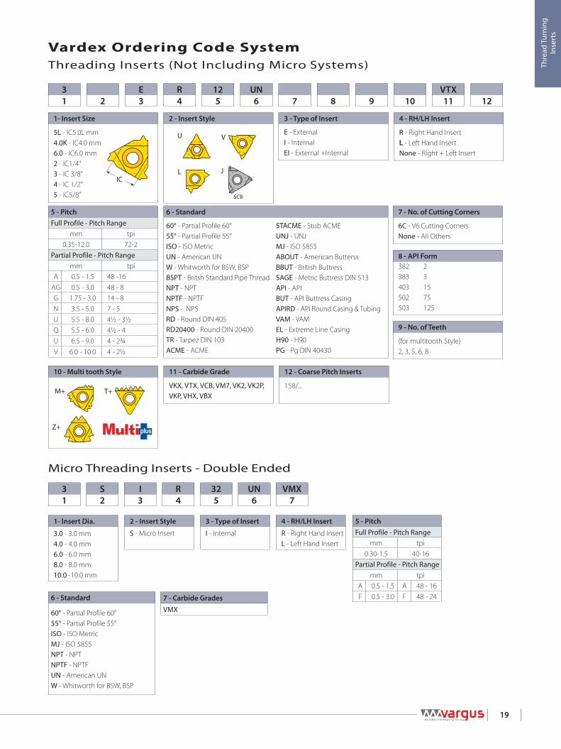
Vardex Ordering Code SystemThreading Inserts (Not Including Micro Systems)
6 - Standard
60° - Partial Profile 60°55° - Partial Profile 55° ISO - ISO MetricMJ - ISO 5855NPT - NPTNPTF - NPTFUN - American UNW - Whitworth for BSW, BSP
7 - Carbide GradesVMX
5 - PitchFull Profile - Pitch Range
mm tpi0.30-1.5 40-16
Partial Profile - Pitch Rangemm tpi
A 0.5 - 1.5 A 48 - 16 F 0.5 - 3.0 F 48 - 24
4 - RH/LH Insert
R - Right Hand InsertL - Left Hand Insert
3 - Type of Insert
I - Internal
2 - Insert Style
S - Micro Insert
1- Insert Dia.
3.0 - 3.0 mm4.0 - 4.0 mm6.0 - 6.0 mm8.0 - 8.0 mm10.0 -10.0 mm
VMX7
UN6
325
R4
I3
S2
31
Micro Threading Inserts - Double Ended
6 - Standard
60° - Partial Profile 60°55° - Partial Profile 55° ISO - ISO MetricUN - American UNW - Whitworth for BSW, BSPBSPT - Britsh Standard Pipe ThreadNPT - NPTNPTF - NPTFNPS - NPSRD - Round DIN 405RD20400 - Round DIN 20400 TR - Tarpez DIN 103ACME - ACME
STACME - Stub ACMEUNJ - UNJMJ - ISO 5855ABOUT - American ButterssBBUT - British ButtressSAGE - Metric Buttress DIN 513API - API BUT - API Buttress CasingAPIRD - API Round Casing & TubingVAM - VAMEL - Extreme Line CasingH90 - H90PG - Pg DIN 40430
5 - PitchFull Profile - Pitch Range
mm tpi0.35-12.0 72-2
Partial Profile - Pitch Rangemm tpi
A 0.5 - 1.5 48 -16AG 0.5 - 3.0 48 - 8G 1.75 - 3.0 14 - 8N 3.5 - 5.0 7 - 5U 5.5 - 8.0 4½ - 3½Q 5.5 - 6.0 4½ - 4U 6.5 - 9.0 4 - 2¾V 6.0 - 10.0 4 - 2½
8 - API Form382383403502503
231575125
12 - Coarse Pitch Inserts
158/...
11 - Carbide Grade
VKX, VTX, VCB, VM7, VK2, VK2P, VKP, VHX, VBX
10 - Multi tooth Style
9 - No. of Teeth
(for multitooth Style)2, 3, 5, 6, 8
7 - No. of Cutting Corners
6C - V6 Cutting CornersNone - All Others
4 - RH/LH Insert
R - Right Hand InsertL - Left Hand InsertNone - Right + Left Insert
3 - Type of Insert
E - ExternalI - InternalEI - External +Internal
1- Insert Size
5L - IC5.0L mm4.0K - IC4.0 mm6.0 - IC6.0 mm2 - IC1/4”3 - IC 3/8”4 - IC 1/2”5 - IC5/8”
12VTX1110987
UN6
125
R4
E32
31
IC
SCB
JL
U V
Z+
M+ T+

L
XY
IC
r LX
IC
T
Y
r
60°
X
L
IC
r
Y
IC
L
Y
X
r
Y
rX
L
IC
20
Thre
ad T
urni
ng
Inse
rts
SCB
SCBSintered
ChipbreakerV6 V Style / Slim ThroatU StyleStandard
External
Internal
External
Partial Profile 60°
V StyleInsert Size Pitch Ordering Code Dimensions inchIC L inch mm tpi RH LH r X Y T Toolholder
5/8”V 1.06 6.0-10.0 4-2.5 5VERV60... 5VELV60... 0.030 0.02 0.20 0.39 NL..-5V-10 (LH)
Slim ThroatInsert Size Pitch Ordering Code Dimensions inchIC L inch mm tpi RH LH r X Y T Toolholder
1/4”V 0.43 0.5-1.5 48-16 2VERA60... 2VELA60... 0.002 0.03 0.09 0.13 NL..-2V (LH)
3/8”V 0.630.5-1.5 48-16 3VERA60... 3VELA60... 0.002 0.04 0.11 0.14
NL..-3V (LH)1.75-3.0 14-8 3VERG60... 3VELG60... 0.011 0.04 0.07 0.140.5-3.0 48-8 3VERAG60... 3VELAG60... 0.003 0.04 0.07 0.14
1/2”V 0.87 3.5-5.0 7-5 4VERN60... 4VELN60... 0.021 0.04 0.09 0.19 NL..-4V (LH)
U StyleInsert Size Pitch Ordering Code Dimensions inch AnvilIC L inch mm tpi RH+LH r X Y RH LH Toolholder
1/2”U 0.87 5.5-8.0 4.5-3.25 4UEIU60... 0.012 0.02 0.43 YE4U YI4U AL..-4U (LH)5/8”U 1.06 6.5-9.0 4-2.75 5UEIU60... 0.015 0.04 0.54 YE5U YI5U AL..-5U (LH)
StandardInsert Size Pitch Ordering Code Dimensions inch AnvilIC L inch mm tpi RH LH r X Y RH LH Toolholder
1/4" 0.43 0.5-1.5 48-16 2ERA60... 2ELA60... 0.002 0.03 0.04 - - NL..-2 (LH)
3/8” 0.630.5-1.5 48-16 3ERA60... 3ELA60... 0.002 0.03 0.04
YE3 YI3 AL..-3 (LH)1.75-3.0 14-8 3ERG60... 3ELG60... 0.011 0.05 0.070.5-3.0 48-8 3ERAG60... 3ELAG60... 0.003 0.05 0.07
3/8”SCB 0.63
0.5-1.5 48-16 3JERA60... 0.002 0.02 0.03YE3 - AL..-31.75-3.0 14-8 3JERG60... 0.011 0.04 0.06
0.5-3.0 48-8 3JERAG60... 0.003 0.04 0.063/8” V6 0.63 0.5-2.0 48-13 3ERS60-6C... 0.002 0.07 0.12 YE3-6C - AL..-31/2” 0.87 3.5-5.0 7-5 4ERN60... 4ELN60... 0.021 0.07 0.10 YE4 YI4 AL..-4 (LH)5/8” 1.06 5.5-6.0 4.5-4 5ERQ60... 5ELQ60... 0.025 0.08 0.12 YE5 YI5 AL..-5 (LH)

L
XY
IC
r L X
IC
Y
rT
60°
IC
L
Y
X
r
X
L
IC
r
YX
Y
L
r
IC
21
Thre
ad T
urni
ng
Inse
rts
SCB
SCBSintered
ChipbreakerV6 V Style U StyleStandard
External
Internal
Internal
Partial Profile 60° (con't)
V StyleInsert Size Pitch Ordering Code Dimensions inchIC L inch mm tpi RH LH r X Y T Toolholder
5/8”V 1.06 6.0-10.0 4-2.5 5VIRV60... 5VILV60... 0.014 0.04 0.17 0.31 NVR..-5V (LH)
U StyleInsert Size Pitch Ordering Code Dimensions inch AnvilIC L inch mm tpi RH+LH r X Y RH LH Toolholder
1/2”U 0.87 5.5-8.0 4.5-3.25 4UEIU60... 0.012 0.02 0.43 YI4U YE4U AVR..-4U (LH)5/8”U 1.06 6.5-9.0 4-2.75 5UEIU60... 0.015 0.04 0.54 YI5U YE5U AVR..-5U (LH)
StandardInsert Size Pitch Ordering Code Dimensions inch AnvilIC L inch mm tpi RH LH r X Y RH LH Toolholder
1/4" 0.43 0.5-1.5 48-16 2IRA60... 2ILA60... 0.002 0.03 0.04 - - NVR..-2 (LH)
1/4"SCB 0.43 0.5-1.5 48-16 2JIRA60... 0.002 0.03 0.03 - - NVR..-2
3/8” 0.630.5-1.5 48-16 3IRA60... 3ILA60... 0.002 0.03 0.04
YI3 YE3 AVR..-3 (LH)1.75-3.0 14-8 3IRG60... 3ILG60... 0.006 0.05 0.070.5-3.0 48-8 3IRAG60... 3ILAG60... 0.002 0.05 0.07
3/8”SCB 0.63
0.5-1.5 48-16 3JIRA60... 0.002 0.02 0.03- AVR..-31.75-3.0 14-8 3JIRG60... 0.006 0.04 0.06 YI3
0.5-3.0 48-8 3JIRAG60... 0.002 0.04 0.06
3/8”V6 0.63 0.5-2.0 48-14 3IRS60-6C... 0.001 0.06 0.10 YI3-6C - AVR..-3
NVRC..-3V6
1/2” 0.87 3.5-5.0 7-5 4IRN60... 4ILN60... 0.012 0.07 0.10 YI4 YE4 AVR..-4 (LH)5/8” 1.06 5.5-6.0 4.5-4 5IRQ60... 5ILQ60... 0.012 0.07 0.11 YI5 YE5 AVR..-5 (LH)

Y
Lr
IC
Yr
IC 5.0 L
60°
F F
FY
L1
L
rd
60°
22
Thre
ad T
urni
ng
Inse
rts
RH-Double Ended
External
Internal
Internal
Mini-LMini-3External
Internal
Internal
Partial Profile 60° (con't)
Micro - Double EndedInsert dia. Pitch Ordering Code Dimensions inch Min. Bore dia.
d mm mm tpi RH/LH r L1 L F Y inch. Toolholder
3.0 0.5-1.0 48-24 3.0SIRF60... 0.002 0.63 1.97 0.06 0.04 0.13 SMC..-3.0
4.0 0.5-1.0 48-24 4.0SIRF60... 0.002 0.63 1.97 0.08 0.04 0.17 SMC..-4.0
6.0 0.5-1.5 48-16 6.0SIRA60... 0.002 0.63 1.97 0.10 0.04 0.24 SMC..-6.0
Left Handed Tool Supplied by Request. (Example: 6.0SILA60...)
Mini-LInsert Size Pitch Ordering Code Dimensions inch Min Bore dia.
IC mm tpi RH r Y F inch Toolholder5.0L 0.5-1.5 48-16 5LIRA60... 0.002 0.04 0.18 0.31 .NVR...-5L
Mini-3Insert Size Pitch Ordering Code Dimensions inch Min. Bore dia.IC L inch mm tpi RH r Y F inch Toolholder4.0 6 0.5-1.25 48-20 4.0KIRA60... 0.002 0.02 0.15 0.25 .NVR.020-4.0K6.0 10 0.5-1.5 48-16 6.0IRA60... 0.002 0.04 0.21 0.39 .NVR...-6.0

IC
L
Y
X
r
55° L
XY
IC
r LX
IC
T
Y
r
Y
rX
L
IC
X
L
IC
r
Y
23
Thre
ad T
urni
ng
Inse
rts
SCB
SCBSintered
ChipbreakerV6 V Style / Slim ThroatU StyleStandard
External
Internal
External
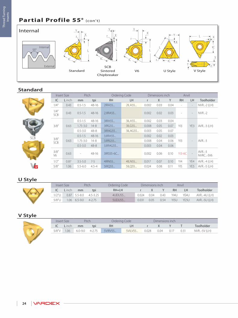
Partial Profile 55°
V StyleInsert Size Pitch Ordering Code Dimensions inchIC L inch mm tpi RH LH r X Y T Toolholder
5/8”V 1.06 6.0-9.0 4-2.75 5VERV55... 5VELV55... 0.028 0.04 0.17 0.31 NL..-5V-8 (LH)
Slim ThroatInsert Size Pitch Ordering Code Dimensions inchIC L inch mm tpi RH LH r X Y T Toolholder
1/4”V 0.43 0.5-1.5 48-16 2VERA55... 2VELA55... 0.002 0.03 0.11 0.13 NL..-2V (LH)
3/8”V0.63
0.5-1.5 48-16 3VERA55... 3VELA55... 0.002 0.04 0.11 0.14NL..-3V (LH)1.75-3.0 14-8 3VERG55... 3VELG55... 0.008 0.04 0.07 0.14
0.5-3.0 48-8 3VERAG55... 3VELAG55... 0.003 0.04 0.07 0.141/2”V 0.87 3.5-5.0 7-5 4VERN55... 4VELN55... 0.017 0.04 0.09 0.19 NL..-4V (LH)
U StyleInsert Size Pitch Ordering Code Dimensions inch AnvilIC L inch mm tpi RH+LH r X Y RH LH Toolholder
1/2”U 0.87 5.5-8.0 4.5-3.25 4UEIU55... 0.024 0.04 0.43 YE4U YI4U AL..-4U (LH)5/8”U 1.06 6.5-9.0 4-2.75 5UEIU55... 0.031 0.05 0.54 YE5U YI5U AL..-5U (LH)
StandardInsert Size Pitch Ordering Code Dimensions inch AnvilIC L inch mm tpi RH LH r X Y RH LH Toolholder
1/4" 0.43 0.5-1.5 48-16 2ERA55... 2ELA55... 0.002 0.03 0.04 - - NL..-2 (LH)
3/8” 0.630.5-1.5 48-16 3ERA55... 3ELA55... 0.002 0.03 0.04
YE3 YI3 AL..-3 (LH)1.75-3.0 14-8 3ERG55... 3ELG55... 0.008 0.05 0.070.5-3.0 48-8 3ERAG55... 3ELAG55... 0.003 0.05 0.07
3/8”SCB 0.63
0.5-1.5 48-16 3JERA55... 0.002 0.02 0.03YE3 - AL..-31.75-3.0 14-8 3JERG55... 0.008 0.04 0.06
0.5-3.0 48-8 3JERAG55... 0.003 0.04 0.063/8”V6 0.63 - 48-14 3ERS55-6C... 0.002 0.07 0.11 YE3-6C - AL..-31/2” 0.87 3.5-5.0 7-5 4ERN55... 4ELN55... 0.017 0.07 0.10 YE4 YI4 AL..-4 (LH)5/8” 1.06 5.5-6.0 4.5-4 5ERQ55... 5ELQ55... 0.024 0.08 0.11 YE5 YI5 AL..-5 (LH)
55° L
XY
IC
r L X
Y
rT
IC
IC
L
Y
X
r
XY
L
r
IC
X
L
IC
r
Y
24
Thre
ad T
urni
ng
Inse
rts
SCB
SCBSintered
ChipbreakerV6 V StyleU StyleStandard
External
Internal
Internal
Partial Profile 55° (con't)
V StyleInsert Size Pitch Ordering Code Dimensions inchIC L inch mm tpi RH LH r X Y T Toolholder
5/8”V 1.06 6.0-9.0 4-2.75 5VIRV55... 5VILV55... 0.028 0.04 0.17 0.31 NVR..-5V (LH)
U StyleInsert Size Pitch Ordering Code Dimensions inch AnvilIC L inch mm tpi RH+LH r X Y RH LH Toolholder
1/2”U 0.87 5.5-8.0 4.5-3.25 4UEIU55... 0.024 0.04 0.43 YI4U YE4U AVR..-4U (LH)5/8”U 1.06 6.5-9.0 4-2.75 5UEIU55... 0.031 0.05 0.54 YI5U YE5U AVR..-5U (LH)
StandardInsert Size Pitch Ordering Code Dimensions inch AnvilIC L inch mm tpi RH LH r X Y RH LH Toolholder
1/4" 0.43 0.5-1.5 48-16 2IRA55... 2ILA55... 0.002 0.03 0.04 - - NVR..-2 (LH)
1/4”SCB 0.43 0.5-1.5 48-16 2JIRA55... 0.002 0.02 0.03 - - NVR..-2
3/8” 0.630.5-1.5 48-16 3IRA55... 3ILA55... 0.002 0.03 0.04
YI3 YE3 AVR..-3 (LH)1.75-3.0 14-8 3IRG55... 3ILG55... 0.008 0.05 0.070.5-3.0 48-8 3IRAG55... 3ILAG55... 0.003 0.05 0.07
3/8”SCB 0.63
0.5-1.5 48-16 3JIRA55... 0.002 0.02 0.03YI3 - AVR..-31.75-3.0 14-8 3JIRG55... 0.008 0.04 0.06
0.5-3.0 48-8 3JIRAG55... 0.003 0.04 0.06
3/8”V6 0.63 - 48-16 3IRS55-6C... 0.002 0.06 0.10 YI3-6C - AVR..-3
NVRC..-3V6
1/2” 0.87 3.5-5.0 7-5 4IRN55... 4ILN55... 0.017 0.07 0.10 YI4 YE4 AVR..-4 (LH)5/8” 1.06 5.5-6.0 4.5-4 5IRQ55... 5ILQ55... 0.024 0.08 0.11 YI5 YE5 AVR..-5 (LH)

Y
Lr
IC
Yr
IC 5.0 L
55°
F F
55°
FY
L1
L
rd
25
Thre
ad T
urni
ng
Inse
rts
RH-Double Ended
External
Internal
Internal
Partial Profile 55°
Mini-LMini-3External
Internal
Internal
Partial Profile 55° (con't)
Micro - Double EndedInsert dia. Pitch Ordering Code Dimensions inch Min. Bore dia.
d mm mm tpi RH/LH r L1 L F Y inch Toolholder
3.0 0.5-1.0 48-24 3.0SIRF55... 0.002 0.63 1.97 0.06 0.04 0.13 SMC..-3.0
4.0 0.5-1.0 48-24 4.0SIRF55... 0.002 0.63 1.97 0.08 0.04 0.17 SMC..-4.0
6.0 0.5-1.5 48-16 6.0SIRA55... 0.002 0.63 1.97 0.10 0.04 0.24 SMC..-6.0
Left Handed Tool Supplied by Request. (Example: 6.0SILA55...)
Mini-LInsert Size Pitch Ordering Code Dimensions inch Min. Bore dia.
IC mm tpi RH r Y F inch Toolholder5.0L 0.5-1.5 48-16 5LIRA55... 0.002 0.04 0.18 0.31 .NVR...-5L
Mini-3Insert Size Pitch Ordering Code Dimensions inch Min Bore dia.IC L inch mm tpi RH r Y F inch Toolholder4.0 0.24 0.5-1.25 48-20 4.0KIRA55... 0.002 0.02 0.15 0.25 .NVR. 020-4.0K6.0 0.39 0.5-1.50 48-16 6.0IRA55... 0.002 0.04 0.21 0.39 .NVR...-6.0
L
XY
IC
1/4P
1/8P
h
60°
26
Thre
ad T
urni
ng
Inse
rts
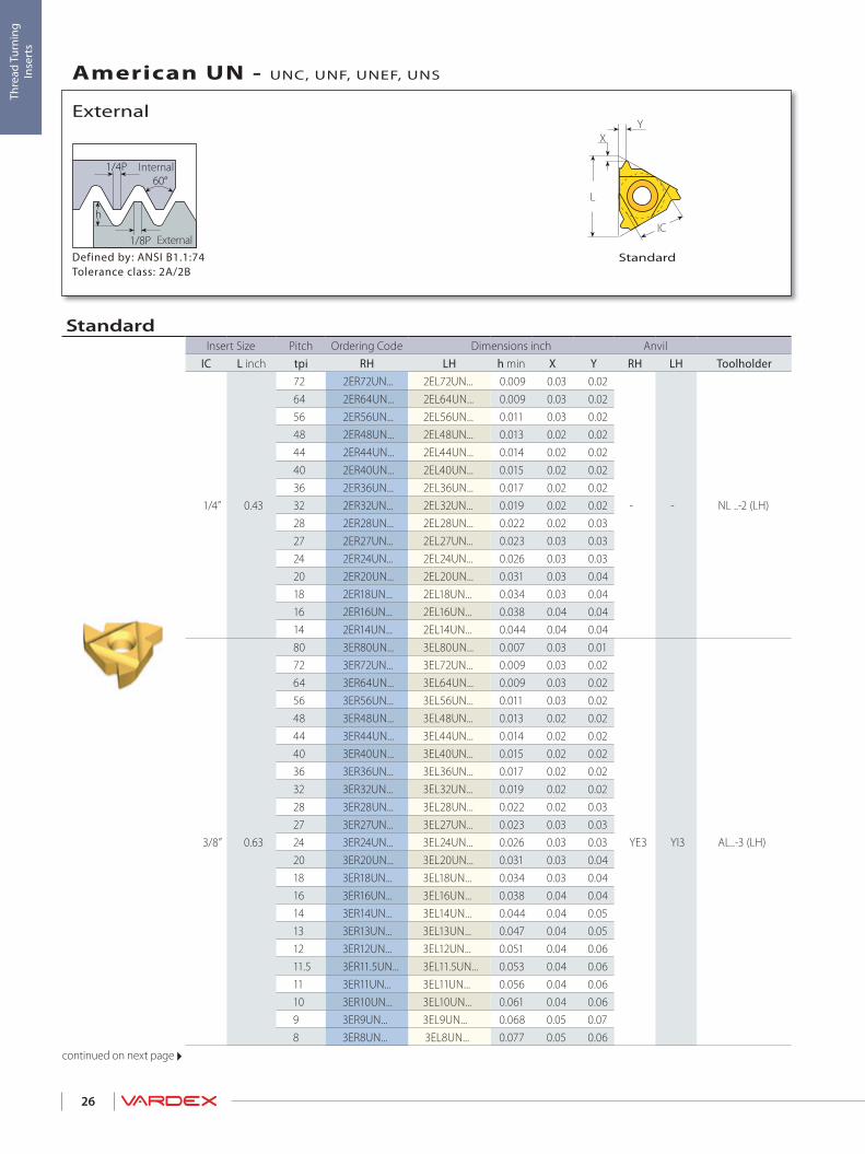
StandardDefined by: ANSI B1.1:74Tolerance class: 2A/2B
External
Internal
External
American UN - UNC, UNF, UNEF, UNS
StandardInsert Size Pitch Ordering Code Dimensions inch Anvil
IC L inch tpi RH LH h min X Y RH LH Toolholder
1/4” 0.43
72 2ER72UN... 2EL72UN... 0.009 0.03 0.02
- - NL ..-2 (LH)
64 2ER64UN... 2EL64UN... 0.009 0.03 0.0256 2ER56UN... 2EL56UN... 0.011 0.03 0.0248 2ER48UN... 2EL48UN... 0.013 0.02 0.0244 2ER44UN... 2EL44UN... 0.014 0.02 0.0240 2ER40UN... 2EL40UN... 0.015 0.02 0.0236 2ER36UN... 2EL36UN... 0.017 0.02 0.0232 2ER32UN... 2EL32UN... 0.019 0.02 0.0228 2ER28UN... 2EL28UN... 0.022 0.02 0.0327 2ER27UN... 2EL27UN... 0.023 0.03 0.0324 2ER24UN... 2EL24UN... 0.026 0.03 0.0320 2ER20UN... 2EL20UN... 0.031 0.03 0.0418 2ER18UN... 2EL18UN... 0.034 0.03 0.0416 2ER16UN... 2EL16UN... 0.038 0.04 0.0414 2ER14UN... 2EL14UN... 0.044 0.04 0.04
3/8” 0.63
80 3ER80UN... 3EL80UN... 0.007 0.03 0.01
YE3 YI3 AL..-3 (LH)
72 3ER72UN... 3EL72UN... 0.009 0.03 0.0264 3ER64UN... 3EL64UN... 0.009 0.03 0.0256 3ER56UN... 3EL56UN... 0.011 0.03 0.0248 3ER48UN... 3EL48UN... 0.013 0.02 0.0244 3ER44UN... 3EL44UN... 0.014 0.02 0.0240 3ER40UN... 3EL40UN... 0.015 0.02 0.0236 3ER36UN... 3EL36UN... 0.017 0.02 0.0232 3ER32UN... 3EL32UN... 0.019 0.02 0.0228 3ER28UN... 3EL28UN... 0.022 0.02 0.0327 3ER27UN... 3EL27UN... 0.023 0.03 0.0324 3ER24UN... 3EL24UN... 0.026 0.03 0.0320 3ER20UN... 3EL20UN... 0.031 0.03 0.0418 3ER18UN... 3EL18UN... 0.034 0.03 0.0416 3ER16UN... 3EL16UN... 0.038 0.04 0.0414 3ER14UN... 3EL14UN... 0.044 0.04 0.0513 3ER13UN... 3EL13UN... 0.047 0.04 0.0512 3ER12UN... 3EL12UN... 0.051 0.04 0.0611.5 3ER11.5UN... 3EL11.5UN... 0.053 0.04 0.0611 3ER11UN... 3EL11UN... 0.056 0.04 0.0610 3ER10UN... 3EL10UN... 0.061 0.04 0.069 3ER9UN... 3EL9UN... 0.068 0.05 0.078 3ER8UN... 3EL8UN... 0.077 0.05 0.06
continued on next page

IC
L
Y
X
L
XY
IC
1/4P
1/8P
h
60°
Y
X
L
IC
X
L
IC
Y
27
Thre
ad T
urni
ng
Inse
rts
SCB
SCBSintered
Chipbreaker
V6 U StyleStandardDefined by: ANSI B1.1:74Tolerance class: 2A/2B
External
Internal
External
American UN - UNC, UNF, UNEF, UNS (con't)
U StyleInsert Size Pitch Ordering Code Dimensions inch Anvil
IC L inch tpi RH+LH h min X Y RH LH Toolholder
1/2”U 0.874.5 4UE4.5UN... 0.136 0.08 0.43
YE4U YI4U AL..-4U (LH)4 4UE4UN... 0.153 0.08 0.43
5/8”U 1.06 3 5UE3UN... 0.204 0.10 0.54 YE5U YI5U AL..-5U (LH)
Standard (con’t)
Insert Size Pitch Ordering Code Dimensions inch AnvilIC L inch tpi RH LH h min X Y RH LH Toolholder
3/8”SCB 0.63
36 3JER36UN... 0.017 0.05 0.02
YE3 - AL..-3
32 3JER32UN... 0.019 0.05 0.0228 3JER28UN... 0.022 0.03 0.0324 3JER24UN... 0.026 0.03 0.0320 3JER20UN... 0.031 0.03 0.0318 3JER18UN... 0.034 0.03 0.0316 3JER16UN... 0.038 0.03 0.0314 3JER14UN... 0.044 0.05 0.0613 3JER13UN... 0.047 0.05 0.0612 3JER12UN... 0.051 0.05 0.0610 3JER10UN... 0.061 0.05 0.069 3JER9UN... 0.068 0.05 0.068 3JER8UN... 0.077 0.05 0.06
3/8”V6 0.63
32 3ER32UN-6C... 0.019 0.08 0.07
YE3-6C - AL..-3
28 3ER28UN-6C... 0.022 0.08 0.0824 3ER24UN-6C... 0.026 0.07 0.0820 3ER20UN-6C... 0.031 0.07 0.0818 3ER18UN-6C... 0.034 0.07 0.0916 3ER16UN-6C... 0.038 0.07 0.0914 3ER14UN-6C... 0.044 0.07 0.1113 3ER13UN-6C... 0.047 0.07 0.1112 3ER12UN-6C... 0.051 0.07 0.09
1/2” 0.877 4ER7UN... 4EL7UN... 0.087 0.06 0.09
YE4 YI4 AL..-4 (LH)6 4ER6UN... 4EL6UN... 0.102 0.06 0.095 4ER5UN... 4EL5UN... 0.123 0.07 0.10
5/8” 1.064.5 5ER4.5UN... 5EL4.5UN... 0.136 0.07 0.11
YE5 YI5 AL..-5 (LH)4 5ER4UN... 5EL4UN... 0.153 0.08 0.12

1/4P
1/8P
h
60°
LX
IC
T
Y
28
Thre
ad T
urni
ng
Inse
rts
Defined by: ANSI B1.1:74Tolerance class: 2A/2B
External
Internal
External
American UN - UNC, UNF, UNEF, UNS (con't)
V Style / Slim Throat
V StyleInsert Size Pitch Ordering Code Dimensions inchIC L inch tpi RH LH h min X Y T Toolholder
5/8”V 1.064 5VER4UN... 5VEL4UN... 0.153 0.04 0.13 0.24 NL..-5V-6 (LH)3 5VER3UN... 5VEL3UN... 0.204 0.04 0.17 0.31 NL..-5V-8 (LH)
Slim ThroatInsert Size Pitch Ordering Code Dimensions inch
IC L inch tpi RH LH h min X Y T Toolholder
1/4”V 0.43
20 2VER20UN... 2VEL20UN... 0.031 0.03 0.09 0.13
NL..-2V (LH)18 2VER18UN... 2VEL18UN... 0.034 0.03 0.09 0.1316 2VER16UN... 2VEL16UN... 0.038 0.03 0.09 0.1314 2VER14UN... 2VEL14UN... 0.044 0.03 0.08 0.1312 2VER12UN... 2VEL12UN... 0.051 0.03 0.07 0.13
3/8”V 0.63
32 3VER32UN... 3VEL32UN... 0.019 0.04 0.12 0.14
NL..-3V (LH)
28 3VER28UN... 3VEL28UN... 0.022 0.04 0.12 0.1424 3VER24UN... 3VEL24UN... 0.026 0.04 0.11 0.1420 3VER20UN... 3VEL20UN... 0.031 0.04 0.11 0.1418 3VER18UN... 3VEL18UN... 0.034 0.04 0.10 0.1416 3VER16UN... 3VEL16UN... 0.038 0.04 0.10 0.1414 3VER14UN... 3VEL14UN... 0.044 0.04 0.09 0.1412 3VER12UN... 3VEL12UN... 0.051 0.04 0.09 0.1410 3VER10UN... 3VEL10UN... 0.061 0.04 0.08 0.148 3VER8UN... 3VEL8UN... 0.077 0.04 0.08 0.14
1/2”V 0.87 7 4VER7UN... 4VEL7UN... 0.087 0.04 0.10 0.19 NL..-4V (LH)

L
X
Y
IC
1/4P
1/8P
h
60°
29
Thre
ad T
urni
ng
Inse
rts
Defined by: ANSI B1.1:74Tolerance class: 2A/2B
External
Internal
External
American UN - UNC, UNF, UNEF, UNS (con't)
M+ Style
M+ Style
Insert Size Pitch Teeth Ordering Code Dimensions inch Anvil
IC L inch tpi RH h min X Y RH Toolholder
3/8” 0.63
20 3 3ER20UN3M+... 0.031 0.09 0.13
YE3M AL..-3
18 2 3ER18UN2M+... 0.034 0.06 0.09
18 3 3ER18UN3M+... 0.034 0.09 0.14
16 2 3ER16UN2M+... 0.038 0.07 0.10
14 2 3ER14UN2M+... 0.044 0.07 0.11
12 2 3ER12UN2M+... 0.051 0.09 0.13
1/2” 0.87
16 3 4ER16UN3M+... 0.038 0.10 0.16
YE4M AL..-4
14 2 4ER14UN2M+... 0.044 0.07 0.11
12 2 4ER12UN2M+... 0.051 0.09 0.13
12 3 4ER12UN3M+... 0.051 0.13 0.21
11 2 4ER11UN2M+... 0.056 0.09 0.14
10 2 4ER10UN2M+... 0.061 0.10 0.15
5/8” 1.06 8 2 5ER8UN2M+... 0.077 0.12 0.19 YE5M AL..-5M
1/4P
1/8P
h
60°L
XY
IC
X
L
IC
Y
30
Thre
ad T
urni
ng
Inse
rts
SCB
SCBSintered
Chipbreaker
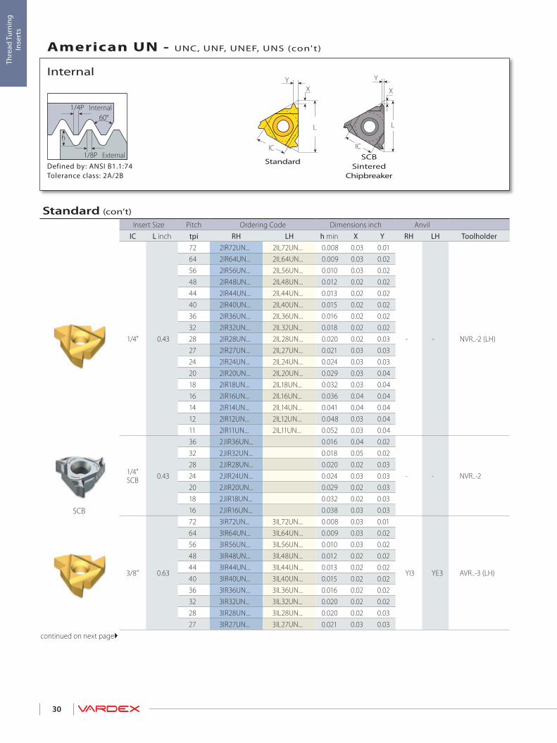
StandardDefined by: ANSI B1.1:74Tolerance class: 2A/2B
External
Internal
Internal
American UN - UNC, UNF, UNEF, UNS (con't)
Standard (con’t)
Insert Size Pitch Ordering Code Dimensions inch AnvilIC L inch tpi RH LH h min X Y RH LH Toolholder
1/4" 0.43
72 2IR72UN... 2IL72UN... 0.008 0.03 0.01
- - NVR..-2 (LH)
64 2IR64UN... 2IL64UN... 0.009 0.03 0.0256 2IR56UN... 2IL56UN... 0.010 0.03 0.0248 2IR48UN... 2IL48UN... 0.012 0.02 0.0244 2IR44UN... 2IL44UN... 0.013 0.02 0.0240 2IR40UN... 2IL40UN... 0.015 0.02 0.0236 2IR36UN... 2IL36UN... 0.016 0.02 0.0232 2IR32UN... 2IL32UN... 0.018 0.02 0.0228 2IR28UN... 2IL28UN... 0.020 0.02 0.0327 2IR27UN... 2IL27UN... 0.021 0.03 0.0324 2IR24UN... 2IL24UN... 0.024 0.03 0.0320 2IR20UN... 2IL20UN... 0.029 0.03 0.0418 2IR18UN... 2IL18UN... 0.032 0.03 0.0416 2IR16UN... 2IL16UN... 0.036 0.04 0.0414 2IR14UN... 2IL14UN... 0.041 0.04 0.0412 2IR12UN... 2IL12UN... 0.048 0.03 0.0411 2IR11UN... 2IL11UN... 0.052 0.03 0.04
1/4”SCB 0.43
36 2JIR36UN... 0.016 0.04 0.02
- - NVR..-2
32 2JIR32UN... 0.018 0.05 0.0228 2JIR28UN... 0.020 0.02 0.0324 2JIR24UN... 0.024 0.03 0.0320 2JIR20UN... 0.029 0.02 0.0318 2JIR18UN... 0.032 0.02 0.0316 2JIR16UN... 0.038 0.03 0.03
3/8” 0.63
72 3IR72UN... 3IL72UN... 0.008 0.03 0.01
YI3 YE3 AVR..-3 (LH)
64 3IR64UN... 3IL64UN... 0.009 0.03 0.0256 3IR56UN... 3IL56UN... 0.010 0.03 0.0248 3IR48UN... 3IL48UN... 0.012 0.02 0.0244 3IR44UN... 3IL44UN... 0.013 0.02 0.0240 3IR40UN... 3IL40UN... 0.015 0.02 0.0236 3IR36UN... 3IL36UN... 0.016 0.02 0.0232 3IR32UN... 3IL32UN... 0.020 0.02 0.0228 3IR28UN... 3IL28UN... 0.020 0.02 0.0327 3IR27UN... 3IL27UN... 0.021 0.03 0.03
continued on next page
1/4P
1/8P
h
60°L
XY
IC
XY
L
IC
X
L
IC
Y
31
Thre
ad T
urni
ng
Inse
rts
SCB
SCBSintered
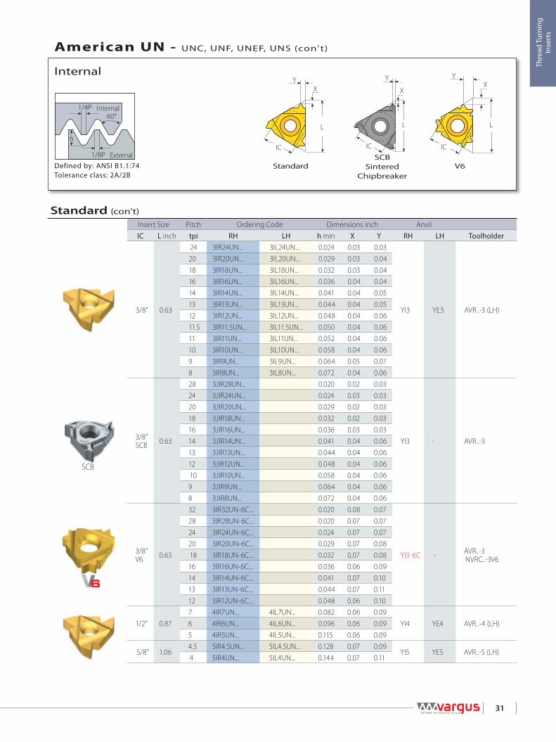
ChipbreakerV6StandardDefined by: ANSI B1.1:74
Tolerance class: 2A/2B
External
Internal
Internal
American UN - UNC, UNF, UNEF, UNS (con't)
Standard (con’t)
Insert Size Pitch Ordering Code Dimensions inch AnvilIC L inch tpi RH LH h min X Y RH LH Toolholder
3/8” 0.63
24 3IR24UN... 3IL24UN... 0.024 0.03 0.03
YI3 YE3 AVR..-3 (LH)
20 3IR20UN... 3IL20UN... 0.029 0.03 0.0418 3IR18UN... 3IL18UN... 0.032 0.03 0.0416 3IR16UN... 3IL16UN... 0.036 0.04 0.0414 3IR14UN... 3IL14UN... 0.041 0.04 0.0513 3IR13UN... 3IL13UN... 0.044 0.04 0.0512 3IR12UN... 3IL12UN... 0.048 0.04 0.0611.5 3IR11.5UN... 3IL11.5UN... 0.050 0.04 0.0611 3IR11UN... 3IL11UN... 0.052 0.04 0.0610 3IR10UN... 3IL10UN... 0.058 0.04 0.069 3IR9UN... 3IL9UN... 0.064 0.05 0.078 3IR8UN... 3IL8UN... 0.072 0.04 0.06
3/8”SCB 0.63
28 3JIR28UN... 0.020 0.02 0.03
YI3 - AVR..-3
24 3JIR24UN... 0.024 0.03 0.0320 3JIR20UN... 0.029 0.02 0.0318 3JIR18UN... 0.032 0.02 0.0316 3JIR16UN... 0.036 0.03 0.0314 3JIR14UN... 0.041 0.04 0.0613 3JIR13UN... 0.044 0.04 0.0612 3JIR12UN... 0.048 0.04 0.0610 3JIR10UN... 0.058 0.04 0.069 3JIR9UN... 0.064 0.04 0.068 3JIR8UN... 0.072 0.04 0.06
3/8”V6 0.63
32 3IR32UN-6C... 0.020 0.08 0.07
YI3-6C - AVR..-3NVRC..-3V6
28 3IR28UN-6C... 0.020 0.07 0.0724 3IR24UN-6C... 0.024 0.07 0.0720 3IR20UN-6C... 0.029 0.07 0.0818 3IR18UN-6C... 0.032 0.07 0.0816 3IR16UN-6C... 0.036 0.06 0.0914 3IR14UN-6C... 0.041 0.07 0.1013 3IR13UN-6C... 0.044 0.07 0.1112 3IR12UN-6C... 0.048 0.06 0.10
1/2” 0.877 4IR7UN... 4IL7UN... 0.082 0.06 0.09
YI4 YE4 AVR..-4 (LH)6 4IR6UN... 4IL6UN... 0.096 0.06 0.095 4IR5UN... 4IL5UN... 0.115 0.06 0.09
5/8” 1.064.5 5IR4.5UN... 5IL4.5UN... 0.128 0.07 0.09
YI5 YE5 AVR..-5 (LH)4 5IR4UN... 5IL4UN... 0.144 0.07 0.11

IC
L
Y
X1/4P
1/8P
h
60°L
XY
IC
32
Thre
ad T
urni
ng
Inse
rts
Defined by: ANSI B1.1:74Tolerance class: 2A/2B
External
Internal
Internal
American UNC
U+ StyleStandard
Coarse PitchThread Insert Size Ordering Code Dimensions inch Min. Bore dia.
IC L inch RH h min X Y Toolholder inch
1/2 x 13UN 6.0 0.39 *6.0IR13UN...158/001 0.044 0.03 0.04 BNVR0375S-6.0 0.42
9/16 x 12UN 1/4”0.43
*2IR12UN...158/002 0.048 0.04 0.04 NVRC040-2 157/001 0.47
5/8 x 11UN 1/4”U 2UIR11UN...158/003 0.052 0.05 0.22 NVRC044-2U 157/002 0.53
3/4 x 10UN
3/8” 0.63
3IR10UN... 0.058 0.04 0.06 NVRC050-3 157/016 0.64
7/8 x 9UN 3IR9UN... 0.064 0.05 0.07 NVRC050-3 157/016 0.76
1 x 8UN 3IR8UN... 0.072 0.04 0.06 NVRC0625-3 0.87
1 1/8 x 7UN
1/2” 0.87
4IR7UN... 0.082 0.06 0.09 NVRC075-4 0.97
1 1/4 x 7UN 4IR7UN... 0.082 0.06 0.09 NVRC075-4 1.09
1 3/8 x 6UN 4IR6UN... 0.096 0.06 0.09 NVRC075-4 1.19
Left Handed Tool Supplied by Request.* For LH order: 6.0IL13UN...158/016, 2IL12UN...158/017.

IC
L
Y
X
L
X
Y
IC
1/4P
1/8P
h
60°
L X
Y
T
IC
33
Thre
ad T
urni
ng
Inse
rts
M+ StyleV StyleU StyleDefined by: ANSI B1.1:74Tolerance class: 2A/2B
External
Internal
Internal
American UN - UNC, UNF, UNEF, UNS (con’t)
M+ StyleInsert Size Pitch Teeth Ordering Code Dimensions inch Anvil
IC L inch tpi RH h min X Y RH Toolholder
3/8” 0.63
12 2 3IR12UN2M+... 0.048 0.09 0.13
YI3M AVR..-314 2 3IR14UN2M+... 0.041 0.07 0.11
16 2 3IR16UN2M+... 0.036 0.07 0.10
1/2” 0.87
16 3 4IR16UN3M+... 0.036 0.10 0.16
YI4M AVR..-414 2 4IR14UN2M+... 0.041 0.07 0.11
12 2 4IR12UN2M+... 0.048 0.09 0.13
12 3 4IR12UN3M+... 0.048 0.13 0.21
5/8” 1.06 8 2 5IR8UN2M+... 0.072 0.12 0.19 YI5M AVR..-5M
V StyleInsert Size Pitch Ordering Code Dimensions inchIC L inch tpi RH LH h min X Y T Toolholder
5/8”V 1.064 5VIR4UN... 5VIL4UN... 0.144 0.04 0.13 0.24
NVR..-5V (LH)3 5VIR3UN... 5VIL3UN... 0.193 0.04 0.17 0.31
U StyleInsert Size Pitch Ordering Code Dimensions inch Anvil
IC L inch tpi RH+LH h min X Y RH LH Toolholder
1/2”U 0.874.5 4UI4.5UN... 0.128 0.09 0.43
YI4U YE4U AVR..-4U (LH)4 4UI4UN... 0.144 0.09 0.43
5/8”U 1.06 3 5UI3UN... 0.193 0.11 0.54 YI5U YE5U AVR..-5U (LH)

Y
L
IC1/4P
1/8P
h
60°
F F
Y
IC 5.0 L
34
Thre
ad T
urni
ng
Inse
rts
Mini-LMini-3Defined by: ANSI B1.1:74Tolerance class: 2A/2B
External
Internal
Internal
American UN - UNC, UNF, UNEF, UNS (con’t)
Left Handed Tool Supplied by Request. (Example: 6.0IL 14UN...)
Mini-LInsert Size Pitch Ordering Code Dimensions inch Min. Bore dia.
IC mm tpi RH h min Y F inch Toolholder
5.0L
32 5LIR32UN... 0.018 0.02 0.15 0.30
.NVR...-5L
28 5LIR28UN... 0.020 0.03 0.16 0.3024 5LIR24UN... 0.024 0.03 0.16 0.3020 5LIR20UN... 0.029 0.04 0.17 0.3118 5LIR18UN... 0.032 0.04 0.17 0.3116 5LIR16UN... 0.036 0.04 0.17 0.3114 5LIR14UN... 0.041 0.04 0.18 0.31
Mini-3Insert Size Pitch Ordering Code Dimensions inch Min. Bore dia.
IC L inch tpi RH h min Y F inch Toolholder
4.0 0.24
32 4.0KIR32UN... 0.018 0.02 0.14 0.24
.NVR.020-4.0K28 4.0KIR28UN... 0.020 0.02 0.14 0.2424 4.0KIR24UN... 0.024 0.02 0.14 0.2520 4.0KIR20UN... 0.029 0.02 0.15 0.2518 4.0KIR18UN... 0.032 0.03 0.15 0.25
6.0 0.39
40 6.0IR40UN... 0.015 0.02 0.18 0.37
.NVR...-6.0
32 6.0IR32UN... 0.018 0.02 0.18 0.3728 6.0IR28UN... 0.020 0.03 0.19 0.3824 6.0IR24UN... 0.024 0.03 0.19 0.3820 6.0IR20UN... 0.029 0.04 0.19 0.3918 6.0IR18UN... 0.032 0.04 0.20 0.3916 6.0IR16UN... 0.036 0.04 0.20 0.3914 6.0IR14UN... 0.041 0.04 0.20 0.39
FY
L1
L
1/4P
1/8P
h60°
d
35
Thre
ad T
urni
ng
Inse
rts
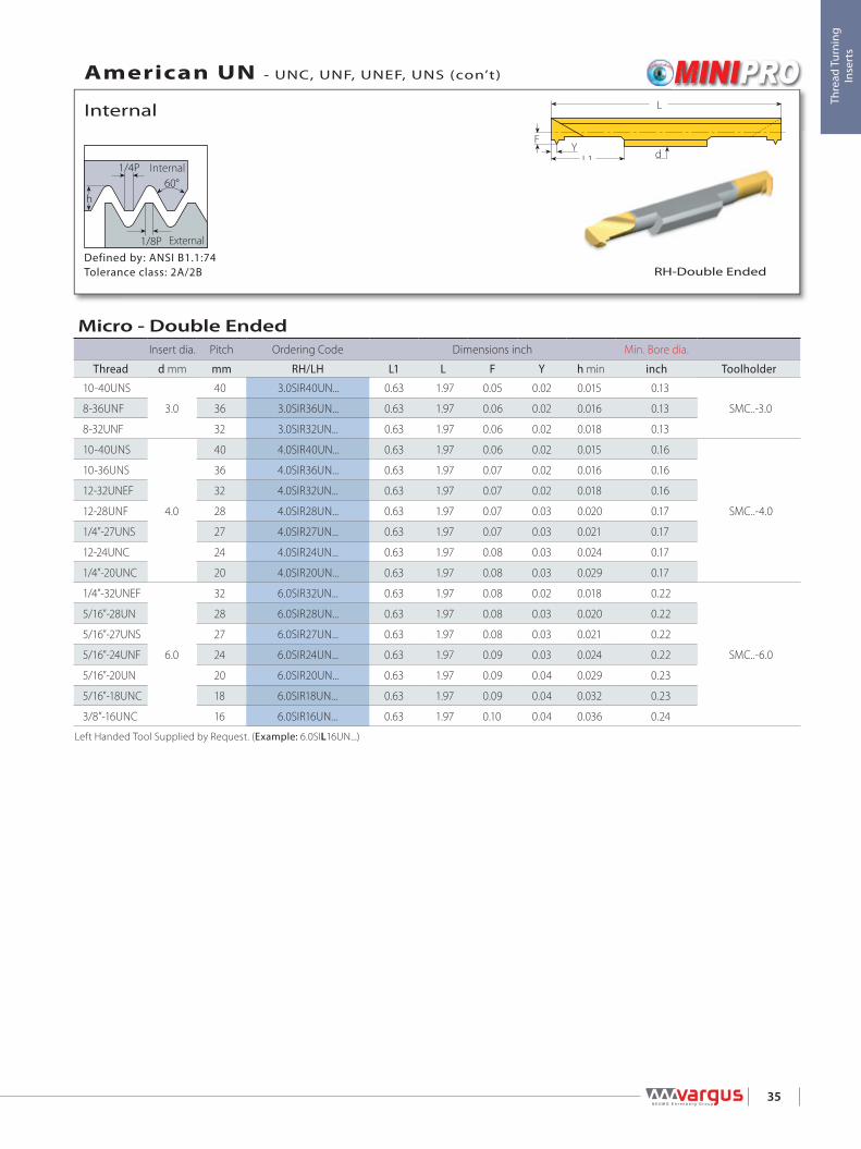
RH-Double EndedDefined by: ANSI B1.1:74Tolerance class: 2A/2B
External
Internal
Internal
American UN - UNC, UNF, UNEF, UNS (con’t)
Micro - Double EndedInsert dia. Pitch Ordering Code Dimensions inch Min. Bore dia.
Thread d mm mm RH/LH L1 L F Y h min inch Toolholder
10-40UNS
3.0
40 3.0SIR40UN... 0.63 1.97 0.05 0.02 0.015 0.13
SMC..-3.08-36UNF 36 3.0SIR36UN... 0.63 1.97 0.06 0.02 0.016 0.13
8-32UNF 32 3.0SIR32UN... 0.63 1.97 0.06 0.02 0.018 0.13
10-40UNS
4.0
40 4.0SIR40UN... 0.63 1.97 0.06 0.02 0.015 0.16
SMC..-4.0
10-36UNS 36 4.0SIR36UN... 0.63 1.97 0.07 0.02 0.016 0.16
12-32UNEF 32 4.0SIR32UN... 0.63 1.97 0.07 0.02 0.018 0.16
12-28UNF 28 4.0SIR28UN... 0.63 1.97 0.07 0.03 0.020 0.17
1/4”-27UNS 27 4.0SIR27UN... 0.63 1.97 0.07 0.03 0.021 0.17
12-24UNC 24 4.0SIR24UN... 0.63 1.97 0.08 0.03 0.024 0.17
1/4”-20UNC 20 4.0SIR20UN... 0.63 1.97 0.08 0.03 0.029 0.17
1/4”-32UNEF
6.0
32 6.0SIR32UN... 0.63 1.97 0.08 0.02 0.018 0.22
SMC..-6.0
5/16”-28UN 28 6.0SIR28UN... 0.63 1.97 0.08 0.03 0.020 0.22
5/16”-27UNS 27 6.0SIR27UN... 0.63 1.97 0.08 0.03 0.021 0.22
5/16”-24UNF 24 6.0SIR24UN... 0.63 1.97 0.09 0.03 0.024 0.22
5/16”-20UN 20 6.0SIR20UN... 0.63 1.97 0.09 0.04 0.029 0.23
5/16”-18UNC 18 6.0SIR18UN... 0.63 1.97 0.09 0.04 0.032 0.23
3/8”-16UNC 16 6.0SIR16UN... 0.63 1.97 0.10 0.04 0.036 0.24
Left Handed Tool Supplied by Request. (Example: 6.0SIL16UN...)
L
XY
IC
1/4P
1/8P
h
60°
36
Thre
ad T
urni
ng
Inse
rts
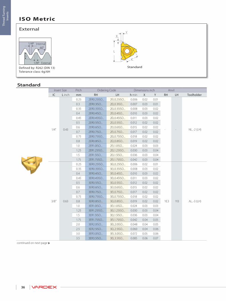
Defined by: R262 (DIN 13)Tolerance class: 6g/6H
Standard
Internal
External
ISO Metric
StandardInsert Size Pitch Ordering Code Dimensions inch Anvil
IC L inch mm RH LH h min X Y RH LH Toolholder
1/4" 0.43
0.25 2ER0.25ISO... 2EL0.25ISO... 0.006 0.02 0.01
- - NL..-2 (LH)
0.3 2ER0.3ISO... 2EL0.3ISO... 0.007 0.03 0.010.35 2ER0.35ISO... 2EL0.35ISO... 0.008 0.03 0.020.4 2ER0.4ISO... 2EL0.4ISO... 0.010 0.03 0.020.45 2ER0.45ISO... 2EL0.45ISO... 0.011 0.03 0.020.5 2ER0.5ISO... 2EL0.5ISO... 0.012 0.02 0.020.6 2ER0.6ISO... 2EL0.6ISO... 0.015 0.02 0.020.7 2ER0.7ISO... 2EL0.7ISO... 0.017 0.02 0.020.75 2ER0.75ISO... 2EL0.75ISO... 0.018 0.02 0.020.8 2ER0.8ISO... 2EL0.8ISO... 0.019 0.02 0.021.0 2ER1.0ISO... 2EL1.0ISO... 0.024 0.03 0.031.25 2ER1.25ISO... 2EL1.25ISO... 0.030 0.03 0.041.5 2ER1.5ISO... 2EL1.5ISO... 0.036 0.03 0.041.75 2ER1.75ISO... 2EL1.75ISO... 0.042 0.03 0.04
3/8” 0.63
0.25 3ER0.25ISO... 3EL0.25ISO... 0.006 0.02 0.01
YE3 YI3 AL..-3 (LH)
0.35 3ER0.35ISO... 3EL0.35ISO... 0.008 0.03 0.020.4 3ER0.4ISO... 3EL0.4ISO... 0.010 0.03 0.020.45 3ER0.45ISO... 3EL0.45ISO... 0.011 0.03 0.020.5 3ER0.5ISO... 3EL0.5ISO... 0.012 0.02 0.020.6 3ER0.6ISO... 3EL0.6ISO... 0.015 0.02 0.020.7 3ER0.7ISO... 3EL0.7ISO... 0.017 0.02 0.020.75 3ER0.75ISO... 3EL0.75ISO... 0.018 0.02 0.020.8 3ER0.8ISO... 3EL0.8ISO... 0.019 0.02 0.021.0 3ER1.0ISO... 3EL1.0ISO... 0.024 0.03 0.031.25 3ER1.25ISO... 3EL1.25ISO... 0.030 0.03 0.041.5 3ER1.5ISO... 3EL1.5ISO... 0.036 0.03 0.041.75 3ER1.75ISO... 3EL1.75ISO... 0.042 0.04 0.052.0 3ER2.0ISO... 3EL2.0ISO... 0.048 0.04 0.052.5 3ER2.5ISO... 3EL2.5ISO... 0.060 0.04 0.063.0 3ER3.0ISO... 3EL3.0ISO... 0.072 0.05 0.063.5 3ER3.5ISO... 3EL3.5ISO... 0.085 0.06 0.07
continued on next page
External

IC
L
Y
X1/4P
1/8P
h
60°L
XY
IC
X
L
IC
Y Y
X
L
IC
37
Thre
ad T
urni
ng
Inse
rts
SCB
SCBSintered
ChipbreakerDefined by: R262 (DIN 13)Tolerance class: 6g/6H
V6 U StyleStandardExternal
Internal
External
ISO Metric (con't)
U StyleInsert Size Pitch Ordering Code Dimensions inch Anvil
IC L inch mm RH+LH h min X Y RH LH Toolholder
1/2”U 0.875.0 4UE5.0ISO... 0.121 0.09 0.43
YE4U YI4U AL..-4U (LH)5.5 4UE5.5ISO... 0.133 0.09 0.436.0 4UE6.0ISO... 0.145 0.10 0.43
5/8”U 1.06 8.0 5UE8.0ISO... 0.193 0.09 0.54 YE5U YI5U AL..-5U (LH)
StandardInsert Size Pitch Ordering Code Dimensions inch Anvil
IC L inch mm RH LH h min X Y RH LH Toolholder
3/8”SCB 0.63
0.5 3JER0.5ISO... 0.012 0.05 0.02
YE3 - AL..-3
0.75 3JER0.75ISO... 0.018 0.05 0.020.8 3JER0.8ISO... 0.019 0.05 0.021.0 3JER1.0ISO... 0.024 0.03 0.031.25 3JER1.25ISO... 0.030 0.03 0.031.5 3JER1.5ISO... 0.036 0.03 0.031.75 3JER1.75ISO... 0.042 0.05 0.062.0 3JER2.0ISO... 0.048 0.05 0.062.5 3JER2.5ISO... 0.060 0.05 0.063.0 3JER3.0ISO... 0.072 0.05 0.063.5 3JER3.5ISO... 0.085 0.05 0.06
3/8”V6 0.63
0.5 3ER0.5ISO-6C... 0.012 0.09 0.07
YE3-6C - AL..-3
0.75 3ER0.75ISO-6C... 0.018 0.08 0.070.8 3ER0.8ISO-6C... 0.019 0.08 0.071.0 3ER1.0ISO-6C... 0.024 0.07 0.081.25 3ER1.25ISO-6C... 0.030 0.07 0.081.5 3ER1.5ISO-6C... 0.036 0.07 0.091.75 3ER1.75ISO-6C... 0.042 0.07 0.102.0 3ER2.0ISO-6C... 0.048 0.07 0.11
1/2” 0.87
3.5 4ER3.5ISO... 4EL3.5ISO... 0.085 0.06 0.09
YE4 YI4 AL..-4 (LH)4.0 4ER4.0ISO... 4EL4.0ISO... 0.096 0.06 0.094.5 4ER4.5ISO... 4EL4.5ISO... 0.109 0.07 0.095.0 4ER5.0ISO... 4EL5.0ISO... 0.121 0.07 0.106.0 4ER6.0ISO... 4EL6.0ISO... 0.145 0.08 0.11
5/8” 1.065.5 5ER5.5ISO... 5EL5.5ISO... 0.133 0.07 0.11
YE5 YI5 AL..-5 (LH)6.0 5ER6.0ISO... 5EL6.0ISO... 0.145 0.08 0.11

1/4P
1/8P
h
60°
LX
IC
T
Y
38
Thre
ad T
urni
ng
Inse
rts
V Style / Slim ThroatDefined by: R262 (DIN 13)Tolerance class: 6g/6H
External
Internal
External
ISO Metric (con't)
V StyleInsert Size Pitch Ordering Code Dimensions inchIC L inch mm RH LH h min X Y T Toolholder
5/8”V 1.06
5.5 5VER5.5ISO... 5VEL5.5ISO... 0.133 0.04 0.13 0.24NL..-5V-6 (LH)
6.0 5VER6.0ISO... 5VEL6.0ISO... 0.145 0.04 0.13 0.248.0 5VER8.0ISO... 5VEL8.0ISO... 0.193 0.04 0.17 0.31 NL..-5V-8 (LH)10.0 5VER10.0ISO... 5VEL10.0ISO... 0.241 0.04 0.20 0.39 NL..-5V-10 (LH)
Slim ThroatInsert Size Pitch Ordering Code Dimensions inchIC L inch mm RH LH h min X Y T Toolholder
1/4”V 0.43
0.75 2VER0.75ISO... 2VEL0.75ISO... 0.018 0.03 0.10 0.13
NL..-2V (LH)1.0 2VER1.0ISO... 2VEL1.0ISO... 0.024 0.03 0.10 0.131.5 2VER1.5ISO... 2VEL1.5ISO... 0.036 0.03 0.09 0.131.75 2VER1.75ISO... 2VEL1.75ISO... 0.042 0.03 0.08 0.132.0 2VER2.0ISO... 2VEL2.0ISO... 0.048 0.03 0.07 0.13
3/8”V 0.63
0.35 3VER0.35ISO... 3VEL0.35ISO... 0.008 0.04 0.13 0.14
NL..-3V (LH)
0.4 3VER0.4ISO... 3VEL0.4ISO... 0.010 0.04 0.13 0.140.5 3VER0.5ISO... 3VEL0.5ISO... 0.012 0.04 0.12 0.140.75 3VER0.75ISO... 3VEL0.75ISO... 0.018 0.04 0.12 0.140.8 3VER0.8ISO... 3VEL0.8ISO... 0.019 0.04 0.12 0.141.0 3VER1.0ISO... 3VEL1.0ISO... 0.024 0.04 0.11 0.141.25 3VER1.25ISO... 3VEL1.25ISO... 0.030 0.04 0.11 0.141.5 3VER1.5ISO... 3VEL1.5ISO... 0.036 0.04 0.10 0.141.75 3VER1.75ISO... 3VEL1.75ISO... 0.042 0.04 0.10 0.142.0 3VER2.0ISO... 3VEL2.0ISO... 0.048 0.04 0.09 0.142.5 3VER2.5ISO... 3VEL2.5ISO... 0.060 0.04 0.08 0.143.0 3VER3.0ISO... 3VEL3.0ISO... 0.072 0.04 0.08 0.14

L
X
Y
IC
L
IC
X
Y
1/4P
1/8P
h
60°
39
Thre
ad T
urni
ng
Inse
rts
T+ StyleM+ StyleDefined by: R262 (DIN 13)Tolerance class: 6g/6H
External
Internal
External
ISO Metric (con't)
T+ StyleInsert Size Pitch Teeth Ordering Code Dimensions inch Anvil
IC L inch mm RH h min X Y RH Toolholder
1/2"T 0.871.5 8 4ER1.5ISO8T+... 0.036 0.01 0.49
Y4T AL..-4T2.0 8 4ER2.0ISO8T+... 0.048 0.01 0.69
M+ StyleInsert Size Pitch Teeth Ordering Code Dimensions inch Anvil
IC L inch mm RH h min X Y RH Toolholder
3/8” 0.631.0 3 3ER1.0ISO3M+... 0.024 0.07 0.10
YE3M AL..-31.5 2 3ER1.5ISO2M+... 0.036 0.06 0.092.0 2 3ER2.0ISO2M+... 0.048 0.08 0.12
1/2” 0.87
1.5 3 4ER1.5ISO3M+... 0.036 0.10 0.15
YE4M AL..-42.0 2 4ER2.0ISO2M+... 0.048 0.08 0.122.0 3 4ER2.0ISO3M+... 0.048 0.13 0.202.5 2 4ER2.5ISO2M+... 0.060 0.10 0.15
5/8” 1.06 3.0 2 5ER3.0ISO2M+... 0.072 0.12 0.19 YE5M AL..-5M

1/4P
1/8P
h
60°L
XY
IC
X
L
IC
Y
40
Thre
ad T
urni
ng
Inse
rts
SCB
SCBSintered
Chipbreaker
StandardDefined by: R262 (DIN 13)Tolerance class: 6g/6H
External
Internal
Internal
ISO Metric (con't)
StandardInsert Size Pitch Ordering Code Dimensions inch Anvil
IC L inch mm RH LH h min X Y RH LH Toolholder
1/4" 0.43
0.35 2IR0.35ISO... 2IL0.35ISO... 0.008 0.03 0.01
- - NVR..-2 (LH)
0.4 2IR0.4ISO... 2IL0.4ISO... 0.009 0.03 0.020.45 2IR0.45ISO... 2IL0.45ISO... 0.010 0.03 0.020.5 2IR0.5ISO... 2IL0.5ISO... 0.011 0.02 0.020.6 2IR0.6ISO... 2IL0.6ISO... 0.014 0.02 0.020.7 2IR0.7ISO... 2IL0.7ISO... 0.016 0.02 0.020.75 2IR0.75ISO... 2IL0.75ISO... 0.017 0.02 0.020.8 2IR0.8ISO... 2IL0.8ISO... 0.018 0.02 0.021.0 2IR1.0ISO... 2IL1.0ISO... 0.023 0.02 0.031.25 2IR1.25ISO... 2IL1.25ISO... 0.028 0.03 0.041.5 2IR1.5ISO... 2IL1.5ISO... 0.034 0.03 0.041.75 2IR1.75ISO... 2IL1.75ISO... 0.040 0.04 0.042.0 2IR2.0ISO... 2IL2.0ISO... 0.045 0.04 0.042.5 2IR2.5ISO... 2IL2.5ISO... 0.057 0.03 0.04
1/4”SCB 0.43
0.5 2JIR0.5ISO... 0.011 0.05 0.02
- - NVR..-2
0.75 2JIR0.75ISO... 0.017 0.05 0.020.8 2JIR0.8ISO... 0.018 0.05 0.021.0 2JIR1.0ISO... 0.023 0.03 0.031.25 2JIR1.25ISO... 0.028 0.03 0.031.5 2JIR1.5ISO... 0.034 0.03 0.03
3/8” 0.63
0.35 3IR0.35ISO... 3IL0.35ISO... 0.008 0.03 0.01
YI3 YE3 AVR..-3 (LH)
0.4 3IR0.4ISO... 3IL0.4ISO... 0.009 0.03 0.020.45 3IR0.45ISO... 3IL0.45ISO... 0.010 0.03 0.020.5 3IR0.5ISO... 3IL0.5ISO... 0.011 0.02 0.020.6 3IR0.6ISO... 3IL0.6ISO... 0.014 0.02 0.020.7 3IR0.7ISO... 3IL0.7ISO... 0.016 0.02 0.020.75 3IR0.75ISO... 3IL0.75ISO... 0.017 0.02 0.020.8 3IR0.8ISO... 3IL0.8ISO... 0.018 0.02 0.021.0 3IR1.0ISO... 3IL1.0ISO... 0.023 0.02 0.031.25 3IR1.25ISO... 3IL1.25ISO... 0.028 0.03 0.041.5 3IR1.5ISO... 3IL1.5ISO... 0.034 0.03 0.041.75 3IR1.75ISO... 3IL1.75ISO... 0.040 0.04 0.052.0 3IR2.0ISO... 3IL2.0ISO... 0.045 0.04 0.052.5 3IR2.5ISO... 3IL2.5ISO... 0.057 0.04 0.063.0 3IR3.0ISO... 3IL3.0ISO... 0.068 0.04 0.063.5 3IR3.5ISO... 3IL3.5ISO... 0.080 0.05 0.06
continued on next page

1/4P
1/8P
h
60°
IC
L
Y
X
L
XY
IC
XY
L
IC
X
L
IC
Y
41
Thre
ad T
urni
ng
Inse
rts
SCB
SCBSintered
Chipbreaker
U StyleV6 StandardDefined by: R262 (DIN 13)Tolerance class: 6g/6H
External
Internal
Internal
ISO Metric (con't)
U StyleInsert Size Pitch Ordering Code Dimensions inch Anvil
IC L inch mm RH+LH h min. X Y RH LH Toolholder
1/2”U 0.875.5 4UI5.5ISO... 0.125 0.09 0.43
YI4U YE4U AVR..-4U (LH)6.0 4UI6.0ISO... 0.136 0.08 0.43
5/8”U 1.06 8.0 5UI8.0ISO... 0.182 0.09 0.54 YI5U YE5U AVR..-5U (LH)
Standard (con’t)
Insert Size Pitch Ordering Code Dimensions inch AnvilIC L inch mm RH LH h min X Y RH LH Toolholder
3/8”SCB
1.0 3JIR1.0ISO... 0.023 0.03 0.03
YI3 - AVR..-30.63
1.25 3JIR1.25ISO... 0.028 0.03 0.031.5 3JIR1.5ISO... 0.034 0.03 0.031.75 3JIR1.75ISO... 0.040 0.04 0.062.0 3JIR2.0ISO... 0.045 0.04 0.062.5 3JIR2.5ISO... 0.057 0.04 0.063.0 3JIR3.0ISO... 0.068 0.04 0.063.5 3JIR3.5ISO... 0.080 0.05 0.06
3/8”V6 0.63
0.5 3IR0.5ISO-6C... 0.011 0.08 0.07
YI3-6C - AVR..-3NVRC..-3V6
0.75 3IR0.75ISO-6C... 0.017 0.08 0.070.8 3IR0.8ISO-6C... 0.018 0.07 0.071.0 3IR1.0ISO-6C... 0.023 0.07 0.061.25 3IR1.25ISO-6C... 0.028 0.07 0.081.5 3IR1.5ISO-6C... 0.034 0.06 0.081.75 3IR1.75ISO-6C... 0.040 0.06 0.092.0 3IR2.0ISO-6C... 0.045 0.07 0.10
1/2”
3.5 4IR3.5ISO... 4IL3.5ISO... 0.080 0.06 0.09
YI4 YE4 AVR..-4 (LH)4.0 4IR4.0ISO... 4IL4.0ISO... 0.091 0.06 0.09
0.87 4.5 4IR4.5ISO... 4IL4.5ISO... 0.102 0.06 0.095.0 4IR5.0ISO... 4IL5.0ISO... 0.114 0.06 0.096.0 4IR6.0ISO... 4IL6.0ISO... 0.136 0.07 0.10
5/8” 1.06
4.5 5IR4.5ISO... 5IL4.5ISO... 0.102 0.06 0.09
YI5 YE5 AVR..-5 (LH)5.0 5IR5.0ISO... 5IL5.0ISO... 0.114 0.06 0.095.5 5IR5.5ISO... 5IL5.5ISO... 0.125 0.06 0.096.0 5IR6.0ISO... 5IL6.0ISO... 0.136 0.07 0.10

L
X
Y
IC
1/4P
1/8P
h
60°
L
IC
X
YL X
Y
T
IC
42
Thre
ad T
urni
ng
Inse
rts
T+ StyleM+ StyleV StyleDefined by: R262 (DIN 13)Tolerance class: 6g/6H
External
Internal
Internal
ISO Metric (con't)
T+ Style
Insert Size Pitch Teeth Ordering Code Dimensions inch AnvilIC L inch mm RH h min X Y RH Toolholder
1/2” 0.871.5 8 4IR1.5ISO8T+... 0.034 0.01 0.49
Y4T AVR..-4T2.0 8 4IR2.0ISO8T+... 0.045 0.01 0.69
V StyleInsert Size Pitch Ordering Code Dimensions inchIC L inch mm RH LH h min X Y T Toolholder
5/8”V 1.066.0 5VIR6.0ISO... 5VIL6.0ISO... 0.136 0.04 0.13 0.24
NVR..-5V (LH)8.0 5VIR8.0ISO... 5VIL8.0ISO... 0.182 0.04 0.17 0.3110.0 5VIR10.0ISO... 5VIL10.0ISO... 0.227 0.04 0.20 0.39
M+ Style
Insert Size Pitch Teeth Ordering Code Dimensions inch Anvil
IC L inch mm RH h min X Y RH Toolholder
3/8” 0.63
1.0 3 3IR1.0ISO3M+... 0.023 0.07 0.10
YI3M AVR..-31.5 2 3IR1.5ISO2M+... 0.034 0.06 0.09
2.0 2 3IR2.0ISO2M+... 0.045 0.08 0.12
1/2” 0.87
1.5 3 4IR1.5ISO3M+... 0.034 0.10 0.15
YI4M AVR..-42.0 2 4IR2.0ISO2M+... 0.045 0.08 0.12
2.0 3 4IR2.0ISO3M+... 0.045 0.13 0.20
5/8” 1.06 3.0 2 5IR3.0ISO2M+... 0.068 0.12 0.19 YI5M AVR..-5M
Y
L
IC1/4P
1/8P
h
60°
Y
IC 5.0 L
F F
43
Thre
ad T
urni
ng
Inse
rts
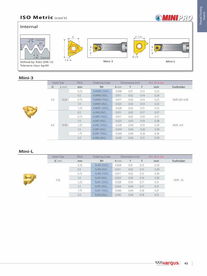
Mini-LMini-3Defined by: R262 (DIN 13)Tolerance class: 6g/6H
External
Internal
Internal
ISO Metric (con't)
Mini-LInsert Size Pitch Ordering Code Dimensions inch Min. Bore dia.
IC mm mm RH h min Y F inch Toolholder
5.0L
0.35 5LIR0.35ISO... 0.008 0.01 0.15 0.29
.NVR...-5L
0.5 5LIR0.5ISO... 0.011 0.02 0.15 0.290.75 5LIR0.75ISO... 0.017 0.02 0.15 0.301.0 5LIR1.0ISO... 0.023 0.03 0.16 0.301.25 5LIR1.25ISO... 0.028 0.04 0.17 0.311.5 5LIR1.5ISO... 0.034 0.04 0.17 0.311.75 5LIR1.75ISO... 0.040 0.04 0.18 0.312.0 5LIR2.0ISO... 0.045 0.04 0.18 0.31
Mini-3Insert Size Pitch Ordering Code Dimensions inch Min. Bore dia.
IC L inch mm RH h min Y F inch Toolholder
4.0 0.24
0.25 4.0KIR0.25ISO... 0.006 0.01 0.13 0.23
.NVR 020-4.0K0.5 4.0KIR0.5ISO... 0.011 0.02 0.14 0.240.75 4.0KIR0.75ISO... 0.017 0.02 0.14 0.251.0 4.0KIR1.0ISO... 0.023 0.03 0.14 0.251.25 4.0KIR1.25ISO... 0.028 0.02 0.15 0.25
6.0 0.39
0.5 6.0IR0.5ISO... 0.011 0.02 0.17 0.37
.NVR..-6.0
0.75 6.0IR0.75ISO... 0.017 0.02 0.18 0.371.0 6.0IR1.0ISO... 0.023 0.03 0.19 0.381.25 6.0IR1.25ISO... 0.028 0.04 0.19 0.391.5 6.0IR1.5ISO... 0.034 0.04 0.20 0.391.75 6.0IR1.75ISO... 0.040 0.04 0.20 0.392.0 6.0IR2.0ISO... 0.045 0.04 0.21 0.39

1/4P
1/8P
h60°
FY
L1
L
d
44
Thre
ad T
urni
ng
Inse
rts
RH-Double Ended
Defined by: R262 (DIN 13)Tolerance class: 6g/6H
External
Internal
Internal
ISO Metric (con't)
Micro - Double EndedInsert dia. Pitch Ordering Code Dimensions inch Min. Bore dia.
Thread d mm mm RH/LH L1 L F Y h min inch ToolholderM4 x 0.3
3.0
0.3 3.0SIR0.3ISO... 0.63 1.97 0.05 0.01 0.007 0.13
SMC..-3.0
M4 x 0.4 0.4 3.0SIR0.4ISO... 0.63 1.97 0.05 0.01 0.009 0.13M4 x 0.5 0.5 3.0SIR0.5ISO... 0.63 1.97 0.05 0.02 0.011 0.13M4 x 0.6 0.6 3.0SIR0.6ISO... 0.63 1.97 0.05 0.02 0.014 0.13M4.5 x 0.7 0.7 3.0SIR0.7ISO... 0.63 1.97 0.06 0.02 0.016 0.13M4.5 x 0.75 0.75 3.0SIR0.75ISO... 0.63 1.97 0.06 0.02 0.017 0.13M5 x 0.8 0.8 3.0SIR0.8ISO... 0.63 1.97 0.06 0.02 0.018 0.13M5 x 0.4
4.0
0.4 4.0SIR0.4ISO... 0.63 1.97 0.06 0.01 0.009 0.16
SMC..-4.0
M5 x 0.5 0.5 4.0SIR0.5ISO... 0.63 1.97 0.06 0.02 0.011 0.16M5 x 0.6 0.6 4.0SIR0.6ISO... 0.63 1.97 0.07 0.02 0.014 0.16M5 x 0.7 0.7 4.0SIR0.7ISO... 0.63 1.97 0.07 0.02 0.016 0.16M5.5 x 0.75 0.75 4.0SIR0.75ISO... 0.63 1.97 0.07 0.02 0.017 0.17M5.5 x 0.8 0.8 4.0SIR0.8ISO... 0.63 1.97 0.07 0.02 0.018 0.17M6 x 1 1.0 4.0SIR1.0ISO... 0.63 1.97 0.08 0.04 0.023 0.17M6 x 0.5
6.0
0.5 6.0SIR0.5ISO... 0.63 1.97 0.07 0.02 0.011 0.21
SMC..-6.0M6.5 x 0.75 0.75 6.0SIR0.75ISO... 0.63 1.97 0.08 0.02 0.017 0.22M7 x 1 1.0 6.0SIR1.0ISO... 0.63 1.97 0.09 0.03 0.023 0.22M8 x 1.25 1.25 6.0SIR1.25ISO... 0.63 1.97 0.09 0.04 0.028 0.23M10.5 x 1.5 1.5 6.0SIR1.5ISO... 0.63 1.97 0.10 0.04 0.034 0.24
Left Handed Tool Supplied by Request. (Example: 3.0SIL0.3ISO...)

L
XY
ICR 0.137Ph
55°R 0.137P
45
Thre
ad T
urni
ng
Inse
rts
StandardDefined by: B.S.84:1956, DIN 259, ISO228/1:1982Tolerance class: Medium class A
External
Internal
External
Whitworth - BSW, BSP, BSF, BSB
StandardInsert Size Pitch Ordering Code Dimensions inch Anvil
IC L inch tpi RH LH h min X Y RH LH Toolholder
1/4" 0.43
72 2ER72W... 2EL72W... 0.009 0.03 0.02
- - NL ..-2 (LH)
60 2ER60W... 2EL60W... 0.011 0.03 0.0256 2ER56W... 2EL56W... 0.011 0.03 0.0248 2ER48W... 2EL48W... 0.013 0.02 0.0240 2ER40W... 2EL40W... 0.016 0.02 0.0236 2ER36W... 2EL36W... 0.018 0.02 0.0232 2ER32W... 2EL32W... 0.020 0.02 0.0228 2ER28W... 2EL28W... 0.023 0.02 0.0326 2ER26W... 2EL26W... 0.025 0.03 0.0324 2ER24W... 2EL24W... 0.027 0.03 0.0322 2ER22W... 2EL22W... 0.029 0.03 0.0420 2ER20W... 2EL20W... 0.032 0.03 0.0419 2ER19W... 2EL19W... 0.034 0.03 0.0418 2ER18W... 2EL18W... 0.035 0.03 0.0416 2ER16W... 2EL16W... 0.040 0.04 0.0414 2ER14W... 2EL14W... 0.046 0.04 0.05
3/8” 0.63
72 3ER72W... 3EL72W... 0.009 0.03 0.02
YE3 YI3 AL..-3 (LH)
60 3ER60W... 3EL60W... 0.011 0.03 0.0256 3ER56W... 3EL56W... 0.011 0.03 0.0248 3ER48W... 3EL48W... 0.013 0.02 0.0240 3ER40W... 3EL40W... 0.016 0.02 0.0236 3ER36W... 3EL36W... 0.018 0.02 0.0232 3ER32W... 3EL32W... 0.020 0.02 0.0230 3ER30W... 3EL30W... 0.022 0.02 0.0328 3ER28W... 3EL28W... 0.023 0.02 0.0326 3ER26W... 3EL26W... 0.025 0.03 0.0324 3ER24W... 3EL24W... 0.027 0.03 0.0322 3ER22W... 3EL22W... 0.029 0.03 0.0420 3ER20W... 3EL20W... 0.032 0.03 0.0419 3ER19W... 3EL19W... 0.034 0.03 0.0418 3ER18W... 3EL18W... 0.035 0.03 0.0416 3ER16W... 3EL16W... 0.040 0.04 0.0414 3ER14W... 3EL14W... 0.046 0.04 0.0512 3ER12W... 3EL12W... 0.054 0.04 0.0611 3ER11W... 3EL11W... 0.058 0.04 0.0610 3ER10W... 3EL10W... 0.064 0.04 0.069 3ER9W... 3EL9W... 0.071 0.05 0.078 3ER8W... 3EL8W... 0.080 0.05 0.06
continued on next page

IC
L
Y
X
R 0.137Ph
55°R 0.137P
L
XY
IC
Y
X
L
IC
X
L
IC
Y
46
Thre
ad T
urni
ng
Inse
rts
SCB
V6SCBSintered
Chipbreaker
U StyleStandardDefined by: B.S.84:1956, DIN 259, ISO228/1:1982Tolerance class: Medium class A
External
Internal
External
Whitworth - BSW, BSP, BSF, BSB (con't)
U StyleInsert Size Pitch Ordering Code Dimensions inch Anvil
IC L inch tpi RH+LH h min X Y RH LH Toolholder
1/2”U 0.87
4.5 4UEI4.5W... 0.142 0.09 0.43
YE4U YI4U AL..-4U (LH)4 4UEI4W... 0.160 0.07 0.433.5 4UEI3.5W... 0.183 0.08 0.433.25 4UEI3.25W... 0.197 0.08 0.43
5/8”U 1.06
3.5 5UEI3.5W... 0.183 0.08 0.54
YE5U YI5U AL..-5U (LH)3.25 5UEI3.25W... 0.197 0.08 0.543 5UEI3W... 0.213 0.09 0.542.75 5UEI2.75W... 0.233 0.09 0.54
Standard (con’t)Insert Size Pitch Ordering Code Dimensions inch Anvil
IC L inch tpi RH LH h min X Y RH LH Toolholder
3/8”SCB 0.63
36 3JER36W... 0.018 0.05 0.02
YE3 - AL..-3
32 3JER32W... 0.020 0.05 0.0228 3JER28W... 0.023 0.03 0.0324 3JER24W... 0.027 0.03 0.0320 3JER20W... 0.032 0.03 0.0319 3JER19W... 0.034 0.03 0.0318 3JER18W... 0.035 0.03 0.0316 3JER16W... 0.040 0.03 0.0314 3JER14W... 0.046 0.05 0.0612 3JER12W... 0.054 0.05 0.0611 3JER11W... 0.058 0.05 0.0610 3JER10W... 0.064 0.05 0.068 3JER8W... 0.080 0.05 0.06
3/8”V6 0.63
19 3ER19W-6C... 0.034 0.07 0.09
YE3-6C - AL..-316 3ER16W-6C... 0.040 0.06 0.0914 3ER14W-6C... 0.046 0.07 0.1112 3ER12W-6C... 0.054 0.07 0.12
1/2” 0.877 4ER7W... 4EL7W... 0.095 0.06 0.09
YE4 YI4 AL..-4 (LH)6 4ER6W... 4EL6W... 0.107 0.06 0.095 4ER5W... 4EL5W... 0.128 0.07 0.09
5/8” 1.064.5 5ER4.5W... 5EL4.5W... 0.142 0.07 0.10
YE5 YI5 AL..-5 (LH)4 5ER4W... 5EL4W... 0.160 0.08 0.11
R 0.137Ph
55°R 0.137P
L
X
Y
IC
LX
IC
T
Y
47
Thre
ad T
urni
ng
Inse
rts
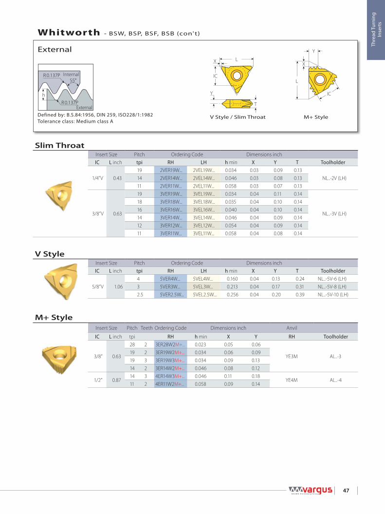
V Style / Slim Throat M+ StyleDefined by: B.S.84:1956, DIN 259, ISO228/1:1982Tolerance class: Medium class A
External
Internal
External
Whitworth - BSW, BSP, BSF, BSB (con't)
M+ StyleInsert Size Pitch Teeth Ordering Code Dimensions inch Anvil
IC L inch tpi RH h min X Y RH Toolholder
3/8” 0.63
28 2 3ER28W2M+... 0.023 0.05 0.06
YE3M AL..-319 2 3ER19W2M+... 0.034 0.06 0.0919 3 3ER19W3M+... 0.034 0.09 0.1314 2 3ER14W2M+... 0.046 0.08 0.12
1/2” 0.8714 3 4ER14W3M+... 0.046 0.11 0.18
YE4M AL..-411 2 4ER11W2M+... 0.058 0.09 0.14
V StyleInsert Size Pitch Ordering Code Dimensions inchIC L inch tpi RH LH h min X Y T Toolholder
5/8”V 1.064 5VER4W... 5VEL4W... 0.160 0.04 0.13 0.24 NL..-5V-6 (LH)3 5VER3W... 5VEL3W... 0.213 0.04 0.17 0.31 NL..-5V-8 (LH)2.5 5VER2.5W... 5VEL2.5W... 0.256 0.04 0.20 0.39 NL..-5V-10 (LH)
Slim ThroatInsert Size Pitch Ordering Code Dimensions inchIC L inch tpi RH LH h min X Y T Toolholder
1/4”V 0.4319 2VER19W... 2VEL19W... 0.034 0.03 0.09 0.13
NL..-2V (LH)14 2VER14W... 2VEL14W... 0.046 0.03 0.08 0.1311 2VER11W... 2VEL11W... 0.058 0.03 0.07 0.13
3/8”V 0.63
19 3VER19W... 3VEL19W... 0.034 0.04 0.11 0.14
NL..-3V (LH)
18 3VER18W... 3VEL18W... 0.035 0.04 0.10 0.1416 3VER16W... 3VEL16W... 0.040 0.04 0.10 0.1414 3VER14W... 3VEL14W... 0.046 0.04 0.09 0.1412 3VER12W... 3VEL12W... 0.054 0.04 0.09 0.1411 3VER11W... 3VEL11W... 0.058 0.04 0.08 0.14
R 0.137Ph
55°R 0.137P
L
XY
IC
X
L
IC
Y
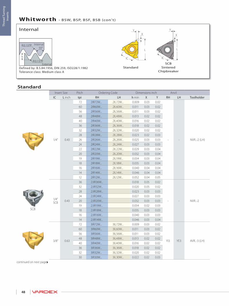
48
Thre
ad T
urni
ng
Inse
rts
StandardSCB
Sintered Chipbreaker
Defined by: B.S.84:1956, DIN 259, ISO228/1:1982Tolerance class: Medium class A
External
Internal
Internal
Whitworth - BSW, BSP, BSF, BSB (con't)
SCB
StandardInsert Size Pitch Ordering Code Dimensions inch Anvil
IC L inch tpi RH LH h min X Y RH LH Toolholder
1/4" 0.43
72 2IR72W... 2IL72W... 0.009 0.03 0.02
- - NVR..-2 (LH)
60 2IR60W... 2IL60W... 0.011 0.03 0.0256 2IR56W... 2IL56W... 0.011 0.03 0.0248 2IR48W... 2IL48W... 0.013 0.02 0.0240 2IR40W... 2IL40W... 0.016 0.02 0.0236 2IR36W... 2IL36W... 0.018 0.02 0.0232 2IR32W... 2IL32W... 0.020 0.02 0.0228 2IR28W... 2IL28W... 0.023 0.02 0.0326 2IR26W... 2IL26W... 0.025 0.03 0.0324 2IR24W... 2IL24W... 0.027 0.03 0.0322 2IR22W... 2IL22W... 0.029 0.03 0.0420 2IR20W... 2IL20W... 0.032 0.03 0.0419 2IR19W... 2IL19W... 0.034 0.03 0.0418 2IR18W... 2IL18W... 0.035 0.03 0.0416 2IR16W... 2IL16W... 0.040 0.04 0.0414 2IR14W... 2IL14W... 0.046 0.04 0.0412 2IR12W... 2IL12W... 0.052 0.04 0.05
1/4”SCB 0.43
36 2JIR36W... 0.018 0.05 0.02
- - NVR..-2
32 2JIR32W... 0.020 0.05 0.0228 2JIR28W... 0.023 0.03 0.0324 2JIR24W... 0.027 0.03 0.0320 2JIR20W... 0.032 0.03 0.0319 2JIR19W... 0.034 0.02 0.0318 2JIR18W... 0.035 0.03 0.0316 2JIR16W... 0.040 0.03 0.0314 2JIR14W... 0.046 0.03 0.04
3/8” 0.63
72 3IR72W... 3IL72W... 0.009 0.03 0.02
YI3 YE3 AVR..-3 (LH)
60 3IR60W... 3IL60W... 0.011 0.03 0.0256 3IR56W... 3IL56W... 0.011 0.03 0.0248 3IR48W... 3IL48W... 0.013 0.02 0.0240 3IR40W... 3IL40W... 0.016 0.02 0.0236 3IR36W... 3IL36W... 0.018 0.02 0.0232 3IR32W... 3IL32W... 0.020 0.02 0.0230 3IR30W... 3IL30W... 0.022 0.02 0.03
continued on next page

R 0.137Ph
55°R 0.137P
L
XY
IC
XY
L
IC
X
L
IC
Y
49
Thre
ad T
urni
ng
Inse
rts
V6Standard
SCBSintered
ChipbreakerDefined by: B.S.84:1956, DIN 259, ISO228/1:1982Tolerance class: Medium class A
External
Internal
Internal
Whitworth - BSW, BSP, BSF, BSB (con't)
SCB
Standard (con’t)
Insert Size Pitch Ordering Code Dimensions inch AnvilIC L inch tpi RH LH h min X Y RH LH Toolholder
3/8” 0.63
28 3IR28W... 3IL28W... 0.023 0.02 0.03
YI3 YE3 AVR..-3 (LH)
26 3IR26W... 3IL26W... 0.025 0.03 0.0324 3IR24W... 3IL24W... 0.027 0.03 0.0322 3IR22W... 3IL22W... 0.029 0.03 0.0420 3IR20W... 3IL20W... 0.032 0.03 0.0419 3IR19W... 3IL19W... 0.034 0.03 0.0418 3IR18W... 3IL18W... 0.035 0.03 0.0416 3IR16W... 3IL16W... 0.040 0.04 0.0414 3IR14W... 3IL14W... 0.046 0.04 0.0512 3IR12W... 3IL12W... 0.054 0.04 0.0611 3IR11W... 3IL11W... 0.058 0.04 0.0610 3IR10W... 3IL10W... 0.064 0.04 0.069 3IR9W... 3IL9W... 0.071 0.05 0.078 3IR8W... 3IL8W... 0.080 0.05 0.06
3/8”SCB 0.63
28 3JIR28W... 0.023 0.03 0.03
YI3 - AVR...-3
24 3JIR24W... 0.027 0.03 0.0320 3JIR20W... 0.032 0.03 0.0319 3JIR19W... 0.034 0.02 0.0218 3JIR18W... 0.035 0.03 0.0316 3JIR16W... 0.040 0.03 0.0314 3JIR14W... 0.046 0.05 0.0612 3JIR12W... 0.054 0.05 0.0611 3JIR11W... 0.058 0.05 0.0610 3JIR10W... 0.064 0.05 0.068 3JIR8W... 0.080 0.05 0.06
3/8”V6 0.63
19 3IR19W-6C... 0.034 0.07 0.09
YI3-6C - AVR..-3NVRC..-3V6
16 3IR16W-6C... 0.040 0.06 0.1014 3IR14W-6C... 0.046 0.07 0.1112 3IR12W-6C... 0.054 0.07 0.10
1/2” 0.877 4IR7W... 4IL7W... 0.095 0.06 0.09
YI4 YE4 AVR..-4 (LH)6 4IR6W... 4IL6W... 0.107 0.06 0.095 4IR5W... 4IL5W... 0.128 0.07 0.09
5/8” 1.064.5 5IR4.5W... 5IL4.5W... 0.142 0.07 0.10
YI5 YE5 AVR..-5 (LH)4 5IR4W... 5IL4W... 0.160 0.08 0.11

IC
L
Y
XL
X
Y
IC
R 0.137Ph
55°R 0.137P
L X
Y
T
IC
50
Thre
ad T
urni
ng
Inse
rts
M+ StyleV StyleU StyleDefined by: B.S.84:1956, DIN 259, ISO228/1:1982Tolerance class: Medium class A
External
Internal
Internal
Whitworth - BSW, BSP, BSF, BSB (con't)
U StyleInsert Size Pitch Ordering Code Dimensions inch Anvil
IC L inch tpi RH+LH h min X Y RH LH Toolholder
1/2”U 0.87
4.5 4UEI4.5W... 0.142 0.09 0.43
YI4U YE4U AVR..-4U (LH)4 4UEI4W... 0.160 0.07 0.433.5 4UEI3.5W... 0.183 0.08 0.433.25 4UEI3.25W... 0.197 0.08 0.43
5/8”U 1.06
3.5 5UEI3.5W... 0.183 0.08 0.54
YI5U YE5U AVR..-5U (LH)3.25 5UEI3.25W... 0.197 0.08 0.543 5UEI3W... 0.213 0.09 0.542.75 5UEI2.75W... 0.233 0.09 0.54
M+ StyleInsert Size Pitch Teeth Ordering Code Dimensions inch Anvil
IC L inch tpi RH h min X Y RH Toolholder
3/8” 0.63 14 2 3IR14W2M+... 0.046 0.08 0.12 YI3M AVR..-3
1/2” 0.87 11 2 4IR11W2M+... 0.058 0.09 0.14 YI4M AVR..-4
V StyleInsert Size Pitch Ordering Code Dimensions inchIC L inch tpi RH LH h min X Y T Toolholder
5/8”V 1.064 5VIR4W... 5VIL4W... 0.160 0.04 0.13 0.24
NVR..-5V (LH)3 5VIR3W... 5VIL3W... 0.213 0.04 0.17 0.312.5 5VIR2.5W... 5VIL2.5W... 0.256 0.04 0.20 0.39

Y
L
IC
Y
IC 5.0 L
R 0.137P
h
55°R 0.137P
F F
51
Thre
ad T
urni
ng
Inse
rts
Defined by: B.S.84:1956, DIN 259, ISO228/1:1982Tolerance class: Medium class A
External
Internal
Internal
Whitworth - BSW, BSP, BSF, BSB (con't)
Mini-LMini-3
Mini-LInsert Size Pitch Ordering Code Dimensions inch Min. Bore dia.
IC mm tpi RH h min Y F inch Toolholder
5.0 L28 5LIR28W... 0.023 0.03 0.16 0.30
.NVR... -5L19 5LIR19W... 0.034 0.04 0.17 0.3114 5LIR14W... 0.046 0.04 0.18 0.31
Mini-3Insert Size Pitch Ordering Code Dimensions inch Min. Bore dia.
IC L inch tpi RH h min Y F inch Toolholder
4.0 0.24
26 4.0KIR26W... 0.025 0.02 0.14 0.25
.NVR.020-4.0K22 4.0KIR22W... 0.029 0.02 0.15 0.2520 4.0KIR20W... 0.032 0.03 0.15 0.2519 4.0KIR19W... 0.034 0.03 0.15 0.2518 4.0KIR18W... 0.035 0.03 0.15 0.25
6.0 0.3928 6.0IR28W... 0.023 0.03 0.19 0.38
.NVR...-6.019 6.0IR19W... 0.034 0.04 0.20 0.3914 6.0IR14W... 0.046 0.04 0.21 0.39

R 0.137P
h
55°R 0.137P
F YL1
L
d
52
Thre
ad T
urni
ng
Inse
rts
RH-Double EndedDefined by: B.S.84:1956, DIN 259, ISO228/1:1982Tolerance class: Medium class A
External
Internal
Internal
Whitworth - BSW, BSP, BSF, BSB (con't)
Micro - Double EndedInsert dia. Pitch Ordering Code Dimensions inch Min. Bore dia.
Thread d mm tpi RH/LH L1 L F Y h min inch Toolholder1/16”-28BSP
4.028 4.0SIR28W... 0.63 1.97 0.07 0.03 0.023 0.17
SMC..-4.01/4”-26BSF 26 4.0SIR26W... 0.63 1.97 0.08 0.03 0.025 0.171/4”-24BSW 24 4.0SIR24W... 0.63 1.97 0.08 0.03 0.027 0.171/16”-28BSP
6.0
28 6.0SIR28W... 0.63 1.97 0.10 0.03 0.023 0.24
SMC..-6.0
5/16”-28BSW 26 6.0SIR26W... 0.63 1.97 0.10 0.03 0.025 0.245/16”-24BSW 24 6.0SIR24W... 0.63 1.97 0.10 0.03 0.027 0.245/16”-22BSW 22 6.0SIR22W... 0.63 1.97 0.10 0.04 0.029 0.243/8”-20BSF 20 6.0SIR20W... 0.63 1.97 0.10 0.04 0.032 0.241/4”-19BSP 19 6.0SIR19W... 0.63 1.97 0.10 0.04 0.034 0.24
Left Handed Tool Supplied by Request. (Example: 6.0SIL19W...)

L
XY
IC
LX
IC
T
Y
Y
X
L
IC
R0.137P27.5° 27.5°
90° 1 47'° R0.137P
X
L
IC
Y
53
Thre
ad T
urni
ng
Inse
rts
V6 Slim ThroatSCBSintered
Chipbreaker
StandardDefined by: B.S. 21:1985Tolerance class: Standard BSPT
External
Internal
External
BSPT
SCB
StandardInsert Size Pitch Ordering Code Dimensions inch Anvil
IC L inch tpi RH LH h min X Y RH LH Toolholder
1/4" 0.4328 2ER28BSPT... 2EL28BSPT... 0.023 0.02 0.02
- - NL ..-2 (LH)19 2ER19BSPT... 2EL19BSPT... 0.034 0.03 0.0414 2ER14BSPT... 2EL14BSPT... 0.046 0.04 0.04
3/8” 0.63
28 3ER28BSPT... 3EL28BSPT... 0.023 0.02 0.02
YE3 YI3 AL..-3 (LH)19 3ER19BSPT... 3EL19BSPT... 0.034 0.03 0.0414 3ER14BSPT... 3EL14BSPT... 0.046 0.04 0.0511 3ER11BSPT... 3EL11BSPT... 0.058 0.04 0.06
3/8”SCB 0.63
28 3JER28BSPT... 0.023 0.03 0.03
YE3 - AL..-319 3JER19BSPT... 0.034 0.03 0.0314 3JER14BSPT... 0.046 0.05 0.0611 3JER11BSPT... 0.058 0.05 0.06
3/8”V6 0.63
19 3ER19BSPT-6C... 0.034 0.07 0.09YE3-6C - AL..-3
14 3ER14BSPT-6C... 0.046 0.07 0.11
Slim ThroatInsert Size Pitch Ordering Code Dimensions inch
IC L inch tpi RH LH h min X Y T Toolholder
3/8”V 0.63
28 3VER28BSPT... 3VEL28BSPT... 0.023 0.04 0.12 0.14
NL..-3V (LH)19 3VER19BSPT... 3VEL19BSPT... 0.034 0.04 0.11 0.1414 3VER14BSPT... 3VEL14BSPT... 0.046 0.04 0.09 0.1411 3VER11BSPT... 3VEL11BSPT... 0.058 0.04 0.08 0.14
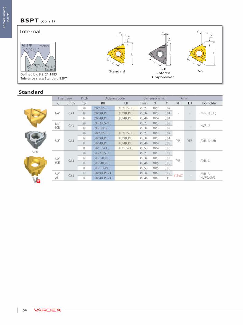
L
XY
IC
XY
L
IC
R0.137P27.5° 27.5°
90° 1 47'° R0.137P
X
L
IC
Y
54
Thre
ad T
urni
ng
Inse
rts
V6SCB
SinteredChipbreaker
StandardDefined by: B.S. 21:1985Tolerance class: Standard BSPT
External
Internal
Internal
BSPT (con't)
SCB
StandardInsert Size Pitch Ordering Code Dimensions inch Anvil
IC L inch tpi RH LH h min X Y RH LH Toolholder
1/4" 0.4328 2IR28BSPT... 2IL28BSPT... 0.023 0.02 0.02
- - NVR..-2 (LH)19 2IR19BSPT... 2IL19BSPT... 0.034 0.03 0.0414 2IR14BSPT... 2IL14BSPT... 0.046 0.04 0.04
1/4”SCB 0.43
28 2JIR28BSPT... 0.023 0.03 0.03- - NVR..-2
19 2JIR19BSPT... 0.034 0.03 0.03
3/8” 0.63
28 3IR28BSPT... 3IL28BSPT... 0.023 0.02 0.02
YI3 YE3 AVR..-3 (LH)19 3IR19BSPT... 3IL19BSPT... 0.034 0.03 0.0414 3IR14BSPT... 3IL14BSPT... 0.046 0.04 0.0511 3IR11BSPT... 3IL11BSPT... 0.058 0.04 0.06
3/8”SCB 0.63
28 3JIR28BSPT... 0.023 0.03 0.03
YI3 - AVR..-3 19 3JIR19BSPT... 0.034 0.03 0.0314 3JIR14BSPT... 0.046 0.05 0.0611 3JIR11BSPT... 0.058 0.05 0.06
3/8”V6 0.63
19 3IR19BSPT-6C... 0.034 0.07 0.09YI3-6C - AVR..-3
NVRC..-3V614 3IR14BSPT-6C... 0.046 0.07 0.11

Y
L
IC
Y
IC 5.0 L
F F
R0.137P27.5° 27.5°
90° 1 47'° R0.137P
55
Thre
ad T
urni
ng
Inse
rts
Mini-LMini-3
Defined by: B.S. 21:1985Tolerance class: Standard BSPT
External
Internal
Internal
BSPT (con't)
Mini-3Insert Size Pitch Ordering Code Dimensions inch Min. Bore dia.
IC L inch tpi RH h min Y F inch Toolholder4.0 0.24 28 4.0KIR28BSPT... 0.023 0.02 0.14 0.25 .NVR.020-4.0K
6.0 0.3928 6.0IR28BSPT... 0.023 0.02 0.19 0.38
.NVR...-6.019 6.0IR19BSPT... 0.034 0.04 0.20 0.3914 6.0IR14BSPT... 0.046 0.05 0.21 0.39
Mini-LInsert Size Pitch Ordering Code Dimensions inch Min. Bore dia.
IC mm tpi RH h min Y F inch Toolholder
5.0L28 5LIR28BSPT... 0.023 0.02 0.16 0.31
.NVR... -5L19 5LIR19BSPT... 0.034 0.04 0.17 0.3114 5LIR14BSPT... 0.046 0.05 0.18 0.31
Left Handed Tool Supplied by Request. (Example: 6.0IL 14BSPT...)

L
XY
IC
LX
IC
T
Y
30°
h
30°
90° 1°47’
Y
X
L
IC
X
L
IC
Y
56
Thre
ad T
urni
ng
Inse
rts
SCBSintered
ChipbreakerSlim ThroatV6StandardDefined by: USAS B2.1:1968
Tolerance class: Standard NPT
External
Internal
External
NPT
SCB
Slim ThroatInsert Size Pitch Ordering Code Dimensions inch
IC L inch tpi RH LH h min X Y T Toolholder
1/4”V 0.43
27 2VER27NPT... 2VEL27NPT... 0.026 0.03 0.08 0.13
NL..-2V (LH)18 2VER18NPT... 2VEL18NPT... 0.040 0.03 0.07 0.1314 2VER14NPT... 2VEL14NPT... 0.052 0.03 0.07 0.1311.5 2VER11.5NPT... 2VEL11.5NPT... 0.065 0.03 0.08 0.13
3/8”V 0.6327 3VER27NPT... 3VEL27NPT... 0.026 0.04 0.11 0.14
NL..-3V (LH)18 3VER18NPT... 3VEL18NPT... 0.040 0.04 0.10 0.1411.5 3VER11.5NPT... 3VEL11.5 NPT... 0.065 0.04 0.08 0.14
StandardInsert Size Pitch Ordering Code Dimensions inch Anvil
IC L inch tpi RH LH h min X Y RH LH Toolholder
1/4" 0.4327 2ER27NPT... 2EL27NPT... 0.026 0.03 0.03
- - NL..-2 (LH)18 2ER18NPT... 2EL18NPT... 0.040 0.03 0.0414 2ER14NPT... 2EL14NPT... 0.052 0.03 0.04
3/8” 0.63
27 3ER27NPT... 3EL27NPT... 0.026 0.03 0.03
YE3 YI3 AL..-3 (LH)18 3ER18NPT... 3EL18NPT... 0.040 0.03 0.0414 3ER14NPT... 3EL14NPT... 0.052 0.04 0.0511.5 3ER11.5NPT... 3EL11.5NPT... 0.065 0.04 0.068 3ER8NPT... 3EL8NPT... 0.095 0.05 0.07
3/8”SCB 0.63
27 3JER27NPT... 0.026 0.02 0.03
YE3 - AL..-318 3JER18NPT... 0.040 0.02 0.0314 3JER14NPT... 0.052 0.04 0.0611.5 3JER11.5NPT... 0.065 0.04 0.068 3JER8NPT... 0.095 0.04 0.06
3/8” V6 0.63 14 3ER14NPT-6C... 0.052 0.07 0.12 YE3-6C - AL..-3
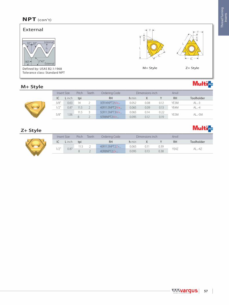
IC
L
Y
X
L
X
Y
IC
30°
h
30°
90° 1°47’
57
Thre
ad T
urni
ng
Inse
rts
M+ Style Z+ StyleDefined by: USAS B2.1:1968Tolerance class: Standard NPT
External
Internal
External
NPT (con't)
Z+ StyleInsert Size Pitch Teeth Ordering Code Dimensions inch Anvil
IC L inch tpi RH h min X Y RH Toolholder
1/2” 0.8711.5 2 4ER11.5NPT2Z+... 0.065 0.11 0.39
YE4Z AL..-4Z8 2 4ER8NPT2Z+... 0.095 0.13 0.38
M+ StyleInsert Size Pitch Teeth Ordering Code Dimensions inch Anvil
IC L inch tpi RH h min X Y RH Toolholder3/8” 0.63 14 2 3ER14NPT2M+... 0.052 0.08 0.12 YE3M AL..-31/2” 0.87 11.5 2 4ER11.5NPT2M+... 0.065 0.09 0.13 YE4M AL..-4
5/8” 1.0611.5 3 5ER11.5NPT3M+... 0.065 0.14 0.22
YE5M AL..-5M8 2 5ER8NPT2M+... 0.095 0.12 0.19

L
X
Y
IC
L
XY
IC
L
IC
Y
X
30°
h
30°
90° 1°47’
XY
L
IC
X
L
IC
Y
58
Thre
ad T
urni
ng
Inse
rts
SCBSintered
Chipbreaker
Z+ StyleM+ StyleV6StandardDefined by: USAS B2.1:1968Tolerance class: Standard NPT
External
Internal
Internal
NPT (con't)
SCB
Z+ StyleInsert Size Pitch Teeth Ordering Code Dimensions inch Anvil
IC L inch tpi RH h min X Y RH Toolholder
1/2” 0.8711.5 2 4IR11.5NPT2Z+... 0.065 0.11 0.39
YI4Z AVR..-4Z8 2 4IR8NPT2Z+... 0.095 0.13 0.38
M+ StyleInsert Size Pitch Teeth Ordering Code Dimensions inch Anvil
IC L inch tpi RH h min X Y RH Toolholder3/8” 0.63 14 2 3IR14NPT2M+... 0.052 0.08 0.12 YI3M AVR..-31/2” 0.87 11.5 2 4IR11.5NPT2M+... 0.065 0.09 0.13 YI4M AVR..-4
5/8” 1.0611.5 3 5IR11.5NPT3M+... 0.065 0.14 0.22
YI5M AVR..-5M8 2 5IR8NPT2M+... 0.095 0.12 0.19
StandardInsert Size Pitch Ordering Code Dimensions inch Anvil
IC L inch tpi RH LH h min X Y RH LH Toolholder
1/4" 0.4327 2IR27NPT... 2IL27NPT... 0.026 0.03 0.03
- - NVR..-2 (LH)18 2IR18NPT... 2IL18NPT... 0.040 0.03 0.0414 2IR14NPT... 2IL14NPT... 0.052 0.03 0.04
1/4"SCB 0.43
27 2JIR27NPT... 0.026 0.02 0.03- - NVR..-2
18 2JIR18NPT... 0.040 0.02 0.03
3/8” 0.63
27 3IR27NPT... 3IL27NPT... 0.026 0.03 0.03
YI3 YE3 AVR..-3 (LH)18 3IR18NPT... 3IL18NPT... 0.040 0.03 0.0414 3IR14NPT... 3IL14NPT... 0.052 0.04 0.0511.5 3IR11.5NPT... 3IL11.5NPT... 0.065 0.04 0.068 3IR8NPT... 3IL8NPT... 0.095 0.05 0.07
3/8”SCB 0.63
27 3JIR27NPT... 0.026 0.02 0.03
YI3 - AVR..-3 18 3JIR18NPT... 0.040 0.02 0.0314 3JIR14NPT... 0.052 0.04 0.0611.5 3JIR11.5NPT... 0.065 0.04 0.068 3JIR8NPT... 0.095 0.04 0.06
3/8” V6 0.63 14 3IR14NPT-6C... 0.052 0.07 0.11 YI3-6C - AVR..-3
NVRC..-3V6

Y
L
IC
F F
Y
IC 5.0 L
30°
h
30°
90° 1°47’
59
Thre
ad T
urni
ng
Inse
rts
Defined by: USAS B2.1:1968Tolerance class: Standard NPT
External
Internal
Internal
NPT (con't)
Mini-LMini-3
Mini-LInsert Size Pitch Ordering Code Dimensions inch Min. Bore dia.
IC mm tpi RH h min Y F inch Toolholder
5.0L27 5LIR27NPT... 0.026 0.03 0.18
0.31 .NVR...-5L18 5LIR18NPT... 0.040 0.04 0.1814 5LIR14NPT... 0.052 0.04 0.18
Mini-3Insert Size Pitch Ordering Code Dimensions inch Min. Bore dia.
IC L inch tpi RH h min Y F inch Toolholder4.0 0.24 27 4.0KIR27NPT... 0.026 0.02 0.15 0.25 .NVR.020-4.0K
6.0 0.3927 6.0IR27NPT... 0.026 0.03 0.21
0.39 .NVR..-6.018 6.0IR18NPT... 0.040 0.04 0.2114 6.0IR14NPT... 0.052 0.04 0.21
Left Handed Tool Supplied by Request. (Example: 4.0KIL 27NPT...)

FY
L1
L
d30°
h
30°
90° 1°47’
60
Thre
ad T
urni
ng
Inse
rts
RH-Double Ended
Defined by: USAS B2.1:1968Tolerance class: Standard NPT
External
Internal
Internal
NPT
Micro - Double EndedInsert dia. Pitch Ordering Code Dimensions inch Min. Bore dia.
Thread d mm mm RH/LH L1 L F Y h min inch Toolholder1/16”-27NPT
6.027 6.0SIR27NPT... 0.63 1.97 0.10 0.04 0.026 0.23
SMC..-6.01/4”-18NPT 18 6.0SIR18NPT... 0.63 1.97 0.10 0.03 0.040 0.24
Left Handed Tool Supplied by Request. (Example: 6.0SIL18NPT...)

L
XY
IC
L
X
Y
IC
30°
h
30°
90° 1°47’
X
L
IC
Y
61
Thre
ad T
urni
ng
Inse
rts
SCBSintered
ChipbreakerM+ StyleStandardDefined by: ANSI B1.20.3-1976
Tolerance class: Class 2
External
Internal
External
NPTF
SCB
M+ StyleInsert Size Pitch Teeth Ordering Code Dimensions inch Anvil
IC L inch tpi RH h min X Y RH Toolholder
3/8” 0.63 14 2 3ER14NPTF2M+... 0.053 0.08 0.12 YE3M AL...-3
StandardInsert Size Pitch Ordering Code Dimensions inch Anvil
IC L inch tpi RH LH h min X Y RH LH Toolholder
1/4” 0.4327 2ER27NPTF... 2EL27NPTF... 0.025 0.03 0.03
- - NL..-2 (LH)18 2ER18NPTF... 2EL18NPTF... 0.039 0.03 0.0414 2ER14NPTF... 2EL14NPTF... 0.053 0.03 0.04
3/8” 0.63
27 3ER27NPTF... 3EL27NPTF... 0.025 0.03 0.03
YE3 YI3 AL..-3 (LH)18 3ER18NPTF... 3EL18NPTF... 0.039 0.03 0.0414 3ER14NPTF... 3EL14NPTF... 0.053 0.04 0.0511.5 3ER11.5NPTF... 3EL11.5NPTF... 0.064 0.04 0.06 8 3ER8NPTF... 3EL8NPTF... 0.094 0.05 0.07
3/8”SCB 0.63
27 3JER27NPTF... 0.025 0.03 0.03
YE3 - AL..-318 3JER18NPTF... 0.039 0.02 0.0314 3JER14NPTF... 0.053 0.04 0.0611.5 3JER11.5NPTF... 0.064 0.04 0.068 3JER8NPTF 0.094 0.04 0.06

L
X
Y
IC
30°
h
30°
90° 1°47’
L
XY
IC
X
L
IC
Y
62
Thre
ad T
urni
ng
Inse
rts
SCBSintered
Chipbreaker
M+ StyleStandardDefined by: ANSI B1.20.3-1976Tolerance class: Class 2
External
Internal
Internal
NPTF (con't)
SCB
M+ StyleInsert Size Pitch Teeth Ordering Code Dimensions inch Anvil
IC L inch tpi RH h min X Y RH Toolholder
3/8” 0.63 14 2 3IR14NPTF2M+... 0.053 0.08 0.12 YI3M AVR..-3
StandardInsert Size Pitch Ordering Code Dimensions inch Anvil
IC L inch tpi RH LH h min X Y RH LH Toolholder
1/4” 0.4327 2IR27NPTF... 2IL27NPTF... 0.025 0.03 0.03
- - NVR..-2 (LH)18 2IR18NPTF... 2IL18NPTF... 0.039 0.03 0.0414 2IR14NPTF... 2IL14NPTF... 0.053 0.03 0.04
1/4”SCB 0.43
27 2JIR27NPTF... 0.025 0.03 0.03- - NVR..-2
18 2JIR18NPTF... 0.039 0.02 0.03
3/8” 0.63
27 3IR27NPTF... 3IL27NPTF... 0.025 0.03 0.03
YI3 YE3 AVR..-3 (LH)18 3IR18NPTF... 3IL18NPTF... 0.039 0.03 0.0414 3IR14NPTF... 3IL14NPTF... 0.053 0.04 0.0511.5 3IR11.5NPTF... 3IL11.5NPTF... 0.064 0.04 0.06 8 3IR8NPTF... 3IL8NPTF... 0.094 0.05 0.07
3/8”SCB 0.63
27 3JIR27NPTF... 0.025 0.03 0.03
YI3 - AVR..-3 18 3JIR18NPTF... 0.039 0.02 0.0314 3JIR14NPTF... 0.053 0.04 0.0611.5 3JIR11.5NPTF... 0.064 0.04 0.068 3JIR8NPTF... 0.094 0.04 0.06

Y
L
IC
Y
IC 5.0 L30°
h
30°
90° 1°47’
F F
30°
h
30°
90° 1°47’
FY
L1
L
d
63
Thre
ad T
urni
ng
Inse
rts
RH-Double EndedDefined by: ANSI B1.20.3-1976Tolerance class: Class 2
External
Internal
Internal
NPTF
Mini-LMini-3Defined by: ANSI B1.20.3-1976Tolerance class: Class 2
External
Internal
Internal
NPTF (con't)
Micro - Double EndedInsert dia. Pitch Ordering Code Dimensions inch Min. Bore dia.
Thread d mm tpi RH/LH L1 L F Y h min inch Toolholder1/16”-27NPTF
6.027 6.0SIR27NPTF... 0.63 1.97 0.10 0.03 0.025
0.24 SMC..-6.01/4”-18NPTF 18 6.0SIR18NPTF... 0.63 1.97 0.10 0.04 0.039
Left Handed Tool Supplied by Request. (Example: 6.0SIL18NPTF...)
Mini-LInsert Size Pitch Ordering Code Dimensions inch Min. Bore dia.
IC mm tpi RH h min Y F inch Toolholder
5.0L27 5LIR27NPTF... 0.025 0.03 0.18
0.31 .NVR...-5L18 5LIR18NPTF... 0.039 0.04 0.1814 5LIR14NPTF... 0.053 0.04 0.18
Mini-3Insert Size Pitch Ordering Code Dimensions inch Min. Bore dia.
IC L inch tpi RH h min Y F inch Toolholder4.0 0.24 27 4.0KIR27NPTF... 0.025 0.02 0.14 0.25 .NVR.020-4.0K
6.0 0.3927 6.0IR27NPTF... 0.025 0.03 0.21
0.39 .NVR..-6.018 6.0IR18NPTF... 0.039 0.04 0.2114 6.0IR14NPTF... 0.053 0.04 0.21

30° 30°
L
XY
IC
L
XY
ICh
64
Thre
ad T
urni
ng
Inse
rts
Internal - StandardExternal - StandardDefined by: USA NBS H28 (1957)Tolerance class: Standard NPS
External
Internal
External / Internal
NPS
Internal
StandardInsert Size Pitch Ordering Code Dimensions inch Anvil
IC L inch tpi RH LH h min X Y RH LH Toolholder
3/8” 0.63
24 3IR24NPS... 3IL24NPS... 0.031 0.03 0.03
YI3 YE3 AVR..-3 (LH)14 3IR14NPS... 3IL14NPS... 0.052 0.04 0.0512 3IR12NPS... 3IL12NPS... 0.064 0.04 0.06
11.5 3IR11.5NPS... 3IL11.5NPS... 0.067 0.04 0.069 3IR9NPS... 3IL9NPS... 0.087 0.05 0.06
1/2” 0.878 4IR8NPS... 4IL8NPS... 0.097 0.05 0.07
YI4 YE4 AVR..-4 (LH)7 4IR7NPS... 4IL7NPS... 0.111 0.06 0.096 4IR6NPS... 4IL6NPS... 0.130 0.06 0.09
5/8” 1.06 5 5IR5NPS... 5IL5NPS... 0.157 0.07 0.11 YI5 YE5 AVR..-5 (LH)
External
StandardInsert Size Pitch Ordering Code Dimensions inch Anvil
IC L inch tpi RH LH h min X Y RH LH Toolholder
3/8” 0.63
24 3ER24NPS... 3EL24NPS... 0.031 0.03 0.03
YE3 YI3 AL..-3 (LH)
16 3ER16NPS... 3EL16NPS... 0.048 0.03 0.0414 3ER14NPS... 3EL14NPS... 0.052 0.04 0.0512 3ER12NPS... 3EL12NPS... 0.064 0.04 0.06
11.5 3ER11.5NPS... 3EL11.5NPS... 0.067 0.04 0.069 3ER9NPS... 3EL9NPS... 0.087 0.05 0.06
1/2” 0.878 4ER8NPS... 4EL8NPS... 0.097 0.05 0.07
YE4 YI4 AL..-4 (LH)7 4ER7NPS... 4EL7NPS... 0.111 0.06 0.096 4ER6NPS... 4EL6NPS... 0.130 0.06 0.09
5/8” 1.06 5 5ER5NPS... 5EL5NPS... 0.157 0.07 0.11 YE5 YI5 AL..-5 (LH)
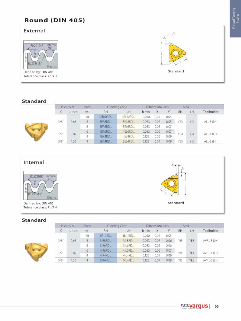
L
XY
ICR0.23851P
R0.22104P30°
hh
L
XY
ICR0.23851P
R0.22104P30°
hh
65
Thre
ad T
urni
ng
Inse
rts
Defined by: DIN 405Tolerance class: 7h/7H
External
Internal
Internal
Standard
Defined by: DIN 405Tolerance class: 7h/7H
External
Internal
External
Round (DIN 405)
Standard
StandardInsert Size Pitch Ordering Code Dimensions inch Anvil
IC L inch tpi RH LH h min X Y RH LH Toolholder
3/8” 0.6310 3IR10RD... 3IL10RD... 0.050 0.04 0.05
YI3 YE3 AVR..-3 (LH)8 3IR8RD... 3IL8RD... 0.063 0.06 0.066 3IR6RD... 3IL6RD... 0.083 0.06 0.06
1/2” 0.876 4IR6RD... 4IL6RD... 0.083 0.06 0.07
YI4 YE4 AVR..-4 (LH)4 4IR4RD... 4IL4RD... 0.125 0.09 0.09
5/8” 1.06 4 5IR4RD... 5IL4RD... 0.125 0.09 0.09 YI5 YE5 AVR..-5 (LH)
StandardInsert Size Pitch Ordering Code Dimensions inch Anvil
IC L inch tpi RH LH h min X Y RH LH Toolholder
3/8” 0.6310 3ER10RD... 3EL10RD... 0.050 0.04 0.05
YE3 YI3 AL..-3 (LH)8 3ER8RD... 3EL8RD... 0.063 0.06 0.056 3ER6RD... 3EL6RD... 0.083 0.06 0.07
1/2” 0.876 4ER6RD... 4EL6RD... 0.083 0.06 0.07
YE4 YI4 AL..-4 (LH)4 4ER4RD... 4EL4RD... 0.125 0.09 0.09
5/8” 1.06 4 5ER4RD... 5EL4RD... 0.125 0.09 0.09 YE5 YI5 AL..-5 (LH)

L
XY
IC IC
L
Y
X
R0.23851PR0.22104P
R0.22104P30°
h
h
L
XY
IC IC
L
Y
X
R0.23851PR0.22104P
R0.22104P30°
h
h
66
Thre
ad T
urni
ng
Inse
rts
U StyleStandardDefined by: DIN 20400Tolerance class: Standard
External
Internal
Internal
Round (DIN 20400)
U StyleStandardDefined by: DIN 20400Tolerance class: Standard
External
Internal
External
Round (DIN 20400)
U StyleInsert Size Pitch Ordering Code Dimensions inch Anvil
IC L inch mm RH+LH h min X Y RH LH Toolholder5/8”U 1.06 8.0 5UEI8.0RD20400... 0.173 0.11 0.53 YI5U YE5U AVR..-5U (LH)
StandardInsert Size Pitch Ordering Code Dimensions inch Anvil
IC L inch mm RH LH h min X Y RH LH Toolholder
1/2” 0.87
3.0 4IR3.0RD20400... 4IL3.0RD20400... 0.065 0.05 0.07
YI4 YE4 AVR..-4 (LH)4.0 4IR4.0RD20400... 4IL4.0RD20400... 0.087 0.06 0.095.0 4IR5.0RD20400... 4IL5.0RD20400... 0.108 0.06 0.076.0 4IR6.0RD20400... 4IL6.0RD20400... 0.130 0.07 0.08
U StyleInsert Size Pitch Ordering Code Dimensions inch Anvil
IC L inch mm RH+LH h min X Y RH LH Toolholder5/8”U 1.06 8.0 5UEI8.0RD20400... 0.173 0.11 0.53 YE5U YI5U AL..-5U (LH)
StandardInsert Size Pitch Ordering Code Dimensions inch Anvil
IC L inch mm RH LH h min X Y RH LH Toolholder
1/2” 0.87
3.0 4ER3.0RD20400... 4EL3.0RD20400... 0.065 0.05 0.07
YE4 YI4 AL..-4 (LH)4.0 4ER4.0RD20400... 4EL4.0RD20400... 0.087 0.06 0.095.0 4ER5.0RD20400... 4EL5.0RD20400... 0.108 0.06 0.076.0 4ER6.0RD20400... 4EL6.0RD20400... 0.13 0.07 0.08

LX
IC
Y
T
L
XY
IC IC
L
Y
X
30°
h
67
Thre
ad T
urni
ng
Inse
rts
V StyleU StyleStandardDefined by: DIN 103Tolerance class: 7e/7H
External
Internal
External
Trapez
V StyleInsert Size Pitch Ordering Code Dimensions inch
IC L inch mm RH LH h min X Y T Toolholder
5/8”V 1.06
6.0 5VER6.0TR... 5VEL6.0TR... 0.138 0.04 0.13 0.24NL..-5V-6 (LH)7.0 5VER7.0TR... 5VEL7.0TR... 0.157 0.04 0.13 0.24
8.0 5VER8.0TR... 5VEL8.0TR... 0.177 0.04 0.13 0.249.0 5VER9.0TR... 5VEL9.0TR... 0.197 0.04 0.17 0.31
NL..-5V-8 (LH)10.0 5VER10.0TR... 5VEL10.0TR... 0.217 0.04 0.17 0.3112.0 5VER12.0TR... 5VEL12.0TR... 0.256 0.04 0.20 0.39 NL..-5V-10 (LH)
U StyleInsert Size Pitch Ordering Code Dimensions inch Anvil
IC L inch mm RH+LH h min X Y RH LH Toolholder
1/2”U 0.876.0 4UE6.0TR... 0.138 0.08 0.43
YE4U YI4U AL..-4U (LH)7.0 4UE7.0TR... 0.157 0.09 0.438.0 4UE8.0TR... 0.177 0.10 0.43
5/8”U 1.068.0 5UE8.0TR... 0.177 0.10 0.54
YE5U YI5U AL..-5U (LH)9.0 5UE9.0TR... 0.197 0.12 0.54
StandardInsert Size Pitch Ordering Code Dimensions inch Anvil
IC L inch mm RH LH h min X Y RH LH Toolholder1/4” 0.43 1.5 2ER1.5TR... 2EL1.5TR... 0.035 0.03 0.04 - - NL..-2 (LH)
3/8” 0.63
1.5 3ER1.5TR... 3EL1.5TR... 0.035 0.04 0.04
YE3 YI3 AL..-3 (LH)2.0 3ER2.0TR... 3EL2.0TR... 0.049 0.04 0.052.5 3ER2.5TR... 3EL2.5TR... 0.061 0.05 0.063.0 3ER3.0TR... 3EL3.0TR... 0.069 0.05 0.06
1/2” 0.874.0 4ER4.0TR... 4EL4.0TR... 0.089 0.07 0.07
YE4 YI4 AL..-4 (LH)5.0 4ER5.0TR... 4EL5.0TR... 0.108 0.08 0.106.0 4ER6.0TR... 4EL6.0TR... 0.138 0.09 0.11
5/8” 1.06 6.0 5ER6.0TR... 5EL6.0TR... 0.138 0.09 0.11 YE5 YI5 AL..-5 (LH)

L
XY
IC
30°
h
IC
L
Y
X
68
Thre
ad T
urni
ng
Inse
rts
U StyleStandardDefined by: DIN 103Tolerance class: 7e/7H
External
Internal
Internal
Trapez (con't)
Coarse PitchThread Insert Size Ordering Code Dimensions inch Min. Bore dia.
IC L inch RH h min X Y Toolholder inchTR18x4 3/8”U 0.63 3UIR4.0TR...158/013 0.089 0.08 0.31 NVRC044-3U 157/020 0.55TR20x4 3/8” 0.63 3IR4.0TR...158/012 0.089 0.06 0.07 NVRC050-3 157/006 0.63TR22x5
3/8”U 0.633UIR5.0TR...158/011 0.108 0.06 0.31 NVRC055-3U 157/018 0.67
TR24x5 3UIR5.0TR...158/011 0.108 0.06 0.31 NVRC059-3U 157/019 0.75TR26x5 3UIR5.0TR...158/011 0.108 0.06 0.31 NVRC059-3U 157/019 0.83TR28x5 1/2” 0.87 4IR5.0TR... 0.108 0.09 0.11 NVRC075-4 157/008 0.91TR30x6 1/2”U 0.87 4UIR6.0TR...158/007 0.138 0.08 0.43 NVRC075-4U 157/011 0.94TR36x6 5/8” 1.06 5IR6.0TR... 0.138 0.09 0.11 NVRC100-5 157/012 1.18TR38x7
1/2”U 0.87
4UIR7.0TR...158/008 0.157 0.09 0.43 NVRC100-4U 157/013 1.22TR40x7 4UIR7.0TR...158/008 0.157 0.09 0.43 NVRC100-4U 157/013 1.30TR42x7 4UIR7.0TR...158/008 0.157 0.09 0.43 NVRC125-4U 157/014 1.38TR44x7 4UIR7.0TR...158/008 0.157 0.09 0.43 NVRC125-4U 157/014 1.46TR46x8
5/8”U 1.06
5UIR8.0TR...158/010 0.177 0.10 0.53 NVRC125-5U 157/015 1.50TR48x8 5UIR8.0TR...158/010 0.177 0.10 0.53 NVRC125-5U 157/015 1.57TR50x8 5UIR8.0TR...158/010 0.177 0.10 0.53 NVRC125-5U 157/015 1.65TR52x8 5UIR8.0TR...158/010 0.177 0.10 0.53 NVRC125-5U 157/015 1.73
Left Handed Tool Supplied by Request.
U Type Inserts Can be Used for LH Applications with LH toolholders.
StandardInsert Size Pitch Ordering Code Dimensions inch Anvil
IC L inch mm RH LH h min X Y RH LH Toolholder1/4” 0.43 1.5 2IR1.5TR... 2IL1.5TR... 0.035 0.03 0.04 - - NVR 8-2 (LH)
3/8” 0.63
1.5 3IR1.5TR... 3IL1.5TR... 0.035 0.04 0.04
YI3 YE3 AVR..-3 (LH)2.0 3IR2.0TR... 3IL2.0TR... 0.049 0.04 0.052.5 3IR2.5TR... 3IL2.5TR... 0.060 0.05 0.063.0 3IR3.0TR... 3IL3.0TR... 0.069 0.05 0.06
1/2” 0.874.0 4IR4.0TR... 4IL4.0TR... 0.089 0.07 0.07
YI4 YE4 AVR..-4 (LH)5.0 4IR5.0TR... 4IL5.0TR... 0.108 0.08 0.106.0 4IR6.0TR... 4IL6.0TR... 0.138 0.09 0.11
5/8” 1.06 6.0 5IR6.0TR... 5IL6.0TR... 0.138 0.09 0.11 YI5 YE5 AVR..-5 (LH)

IC
L
Y
X
LX
IC
Y
T
30°
h
Y
IC 5.0 L
Y
L
IC 6.030°
hF F
69
Thre
ad T
urni
ng
Inse
rts
Mini-LMini-3
U Style V Style
Defined by: DIN 103Tolerance class: 7e/7H
Defined by: DIN 103Tolerance class: 7e/7H
External
External
Internal
Internal
Internal
Internal
Trapez (con't)
Mini-LInsert Size Pitch Ordering Code Dimensions inch Min. Bore dia.
IC mm mm RH h min Y F inch Toolholder
5.0L1.5 5LIR1.5TR... 0.033 0.03 0.18 0.31
.NVR... -5L2.0 5LIR2.0TR... 0.049 0.05 0.18 0.31
Left Handed Tool Supplied by Request. (Example: 6.0IL2.0TR...)
Mini-3Insert Size Pitch Ordering Code Dimensions inch Min. Bore dia.
IC L inch mm RH h min Y F inch Toolholder
6.0 0.391.5 6.0IR1.5TR... 0.033 0.03 0.21 0.39
.NVR...-6.02.0 6.0IR2.0TR... 0.049 0.05 0.21 0.39
V StyleInsert Size Pitch Ordering Code Dimensions inch
IC L inch mm RH LH h min X Y T Toolholder
5/8”V 1.06
6.0 5VIR6.0TR... 5VIL6.0TR... 0.138 0.04 0.13 0.24
NVR..-5V (LH)
7.0 5VIR7.0TR... 5VIL7.0TR... 0.157 0.04 0.13 0.248.0 5VIR8.0TR... 5VIL8.0TR... 0.177 0.04 0.13 0.249.0 5VIR9.0TR... 5VIL9.0TR... 0.197 0.04 0.17 0.3110.0 5VIR10.0TR... 5VIL10.0TR... 0.217 0.04 0.17 0.3112.0 5VIR12.0TR... 5VIL12.0TR... 0.256 0.04 0.20 0.39
U StyleInsert Size Pitch Ordering Code Dimensions inch Anvil
IC L inch mm RH+LH h min X Y RH LH Toolholder
1/2”U 0.876.0 4UI6.0TR... 0.138 0.08 0.43
YI4U YE4U AVR..-4U (LH)7.0 4UI7.0TR... 0.157 0.09 0.438.0 4UI8.0TR... 0.177 0.10 0.43
5/8”U 1.068.0 5UI8.0TR... 0.177 0.10 0.54
YI5U YE5U AVR..-5U (LH)9.0 5UI9.0TR... 0.197 0.12 0.54

IC
L
Y
X
L
XY
IC
LX
IC
Y
T
29°
h
70
Thre
ad T
urni
ng
Inse
rts
V StyleU StyleStandardDefined by: ANSI B1.5:1988Tolerance class: 3G
External
Internal
External
American ACME
V StyleInsert Size Pitch Ordering Code Dimensions inchIC L inch tpi RH LH h min X Y T Toolholder
5/8”V 1.06
4 5VER4ACME... 5VEL4ACME... 0.135 0.04 0.13 0.24NL..-5V-6 (LH)3.5 5VER3.5ACME... 5VEL3.5ACME... 0.152 0.04 0.13 0.24
3 5VER3ACME... 5VEL3ACME... 0.177 0.04 0.13 0.242 5VER2ACME... 5VEL2ACME... 0.26 0.04 0.20 0.39 NL..-5V-10 (LH)
U StyleInsert Size Pitch Ordering Code Dimensions inch Anvil
IC L inch tpi RH+LH h min X Y RH LH Toolholder
1/2”U 0.873 4UE3ACME... 0.177 0.12 0.43
YE4U YI4U AL..-4U (LH)4 4UE4ACME... 0.135 0.09 0.43
5/8”U 1.06 3 5UE3ACME... 0.177 0.12 0.54 YE5U YI5U AL..-5U (LH)
StandardInsert Size Pitch Ordering Code Dimensions inch Anvil
IC L inch tpi RH LH h min X Y RH LH Toolholder1/4" 0.43 16 2ER16ACME... 2EL16ACME... 0.036 0.04 0.04 - - NL..-2 (LH)
3/8” 0.63
16 3ER16ACME... 3EL16ACME... 0.036 0.04 0.04
YE3 YI3AL..-3 (LH)
14 3ER14ACME... 3EL14ACME... 0.041 0.04 0.0512 3ER12ACME... 3EL12ACME... 0.047 0.04 0.0510 3ER10ACME... 3EL10ACME... 0.060 0.05 0.068 3ER8ACME... 3EL8ACME... 0.072 0.06 0.067 3ER7ACME... 3EL7ACME... 0.082 0.07 0.096 3ER6ACME... 3EL6ACME... 0.093 0.07 0.07 YE3AC6 YI3AC6
1/2” 0.877 4ER7ACME... 4EL7ACME... 0.082 0.07 0.09
YE4 YI4 AL..-4 (LH)6 4ER6ACME... 4EL6ACME... 0.093 0.07 0.085 4ER5ACME... 4EL5ACME... 0.110 0.08 0.09
5/8” 1.06 4 5ER4ACME... 5EL4ACME... 0.135 0.09 0.11 YE5 YI5 AL..-5 (LH)

IC
L
Y
X
L
XY
IC
29°
h
71
Thre
ad T
urni
ng
Inse
rts
U StyleStandardDefined by: ANSI B1.5:1988Tolerance class: 3G
External
Internal
Internal
American ACME (con't)
U StyleInsert Size Pitch Ordering Code Dimensions inch Anvil
IC L inch tpi RH+LH h min X Y RH LH Toolholder
1/2”U 0.874 4UI4ACME... 0.135 0.09 0.43
YI4U YE4U AVR..-4U (LH)3 4UI3ACME... 0.177 0.11 0.43
5/8”U 1.06 3 5UI3ACME... 0.177 0.11 0.54 YI5U YE5U AVR..-5U(LH)
Coarse PitchThread Insert Size Ordering Code Dimensions inch Anvil Min. Bore dia.
tpi IC L inch RH h min X Y RH Toolholder inch1/2”x10 6.0U 10 6.0UIR10ACME...158/005 0.060 0.04 0.20 - NVRC 032-6.0U 157/003 0.405/8”x8 1/4”U 11 2UIR8ACME...158/006 0.072 0.04 0.22 - NVRC 039-2U 157/004 0.503/4”x6
3/8” 163IR6ACME... 0.093 0.07 0.07 - NVRC 044-3 157/005 0.58
7/8”x6 3IR6ACME... 0.093 0.07 0.07 - NVRC 050-3 157/006 0.731”x5
1/2” 224IR5ACME... 0.110 0.08 0.09 - NVRC 067-4 157/007 0.80
1 1/8”x5 4IR5ACME... 0.110 0.08 0.09 - NVRC 075-4 157/008 0.941 1/4”x5 4IR5ACME... 0.110 0.08 0.09 - NVRC 075-4 157/009 1.071 1/2”x4
5/8” 275IR4ACME... 0.135 0.09 0.10 - NVRC 110-5 157/010 1.27
1 3/4”x4 5IR4ACME... 0.135 0.09 0.10 YI5-1P AVRC 125-5 1.53Left Handed Tool Supplied by Request.
StandardInsert Size Pitch Ordering Code Dimensions inch Anvil
IC L inch tpi RH LH h min X Y RH LH Toolholder1/4" 0.43 16 2IR16ACME... 2IL16ACME... 0.036 0.04 0.04 - - NVR..-2 (LH)
3/8” 0.63
16 3IR16ACME... 3IL16ACME... 0.036 0.04 0.04
YI3 YE3AVR..-3 (LH)
14 3IR14ACME... 3IL14ACME... 0.041 0.04 0.0512 3IR12ACME... 3IL12ACME... 0.047 0.05 0.0510 3IR10ACME... 3IL10ACME... 0.060 0.05 0.058 3IR8ACME... 3IL8ACME... 0.072 0.06 0.066 3IR6ACME... 3IL6ACME... 0.093 0.07 0.07 YI3AC6 YE3AC6
1/2” 0.876 4IR6ACME... 4IL6ACME... 0.093 0.07 0.08
YI4 YE4 AVR..-4 (LH)5 4IR5ACME... 4IL5ACME... 0.110 0.08 0.09
5/8” 1.06 4 5IR4ACME... 5IL4ACME... 0.135 0.09 0.10 YI5 YE5 AVR..-5 (LH)

LX
IC
Y
T
29°
h
Y
IC 5.0 L29°
h
Y
L
IC 6.0
F F
72
Thre
ad T
urni
ng
Inse
rts
Mini-LMini-3Defined by: ANSI B1.5:1988Tolerance class: 3G
External
Internal
Internal
V StyleDefined by: ANSI B1.5:1988Tolerance class: 3G
External
Internal
Internal
American ACME (con't)
Mini-LInsert Size Pitch Ordering Code Dimensions inch Min. Bore dia.
IC mm tpi RH h min Y F inch Toolholder5.0L 12 5LIR12ACME... 0.047 0.04 0.17 0.31 .NVR... -5L
Left Handed Tool Supplied by Request. (Example: 6.0IL12ACME...)
Mini-3Insert Size Pitch Ordering Code Dimensions inch Min. Bore dia.
IC L inch tpi RH h min Y F inch Toolholder6.0 0.39 12 6.0IR12ACME... 0.047 0.04 0.20 0.39 .NVR...-6.0
V StyleInsert Size Pitch Ordering Code Dimensions inchIC L inch tpi RH LH h min X Y T Toolholder
5/8”V 1.06
4 5VIR4ACME... 5VIL4ACME... 0.135 0.04 0.13 0.24
NVR..-5V (LH)3.5 5VIR3.5ACME... 5VIL3.5ACME... 0.152 0.04 0.13 0.243 5VIR3ACME... 5VIL3ACME... 0.177 0.04 0.13 0.242 5VIR2ACME... 5VIL2ACME... 0.260 0.04 0.20 0.39
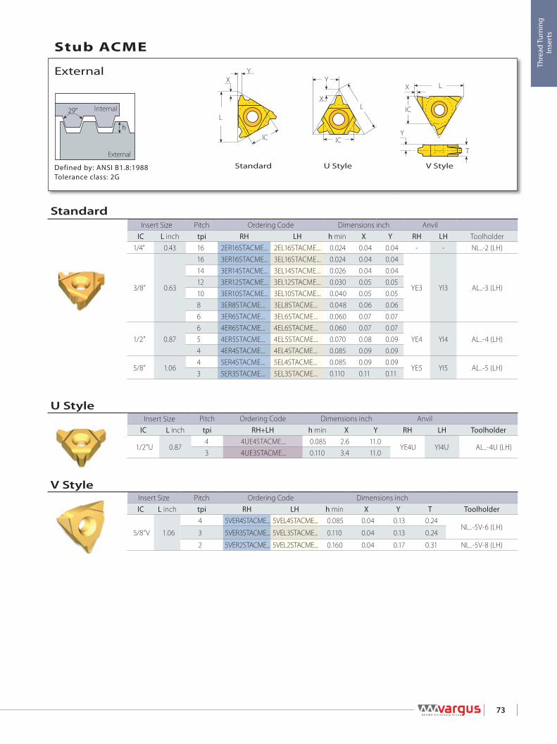
L
XY
IC IC
L
Y
X
LX
IC
Y
T
h
29°
73
Thre
ad T
urni
ng
Inse
rts
Standard U Style V StyleDefined by: ANSI B1.8:1988Tolerance class: 2G
External
Internal
External
Stub ACME
V StyleInsert Size Pitch Ordering Code Dimensions inchIC L inch tpi RH LH h min X Y T Toolholder
5/8”V 1.06
4 5VER4STACME... 5VEL4STACME... 0.085 0.04 0.13 0.24NL..-5V-6 (LH)
3 5VER3STACME... 5VEL3STACME... 0.110 0.04 0.13 0.24
2 5VER2STACME... 5VEL2STACME... 0.160 0.04 0.17 0.31 NL..-5V-8 (LH)
U StyleInsert Size Pitch Ordering Code Dimensions inch Anvil
IC L inch tpi RH+LH h min X Y RH LH Toolholder
1/2”U 0.874 4UE4STACME... 0.085 2.6 11.0
YE4U YI4U AL..-4U (LH)3 4UE3STACME... 0.110 3.4 11.0
StandardInsert Size Pitch Ordering Code Dimensions inch Anvil
IC L inch tpi RH LH h min X Y RH LH Toolholder1/4" 0.43 16 2ER16STACME... 2EL16STACME... 0.024 0.04 0.04 - - NL..-2 (LH)
3/8” 0.63
16 3ER16STACME... 3EL16STACME... 0.024 0.04 0.04
YE3 YI3 AL..-3 (LH)
14 3ER14STACME... 3EL14STACME... 0.026 0.04 0.0412 3ER12STACME... 3EL12STACME... 0.030 0.05 0.0510 3ER10STACME... 3EL10STACME... 0.040 0.05 0.058 3ER8STACME... 3EL8STACME... 0.048 0.06 0.066 3ER6STACME... 3EL6STACME... 0.060 0.07 0.07
1/2” 0.876 4ER6STACME... 4EL6STACME... 0.060 0.07 0.07
YE4 YI4 AL..-4 (LH)5 4ER5STACME... 4EL5STACME... 0.070 0.08 0.094 4ER4STACME... 4EL4STACME... 0.085 0.09 0.09
5/8” 1.064 5ER4STACME... 5EL4STACME... 0.085 0.09 0.09
YE5 YI5 AL..-5 (LH)3 5ER3STACME... 5EL3STACME... 0.110 0.11 0.11
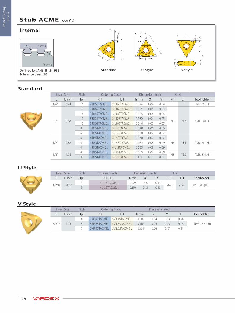
L
XY
IC IC
L
Y
X
LX
IC
Y
T
h
29°
74
Thre
ad T
urni
ng
Inse
rts
Standard V StyleU StyleDefined by: ANSI B1.8:1988Tolerance class: 2G
External
Internal
Internal
Stub ACME (con't)
V StyleInsert Size Pitch Ordering Code Dimensions inch
IC L inch tpi RH LH h min X Y T Toolholder
5/8”V 1.064 5VIR4STACME... 5VIL4STACME... 0.085 0.04 0.13 0.24
NVR..-5V (LH)3 5VIR3STACME... 5VIL3STACME... 0.110 0.04 0.13 0.242 5VIR2STACME... 5VIL2STACME... 0.160 0.04 0.17 0.31
U StyleInsert Size Pitch Ordering Code Dimensions inch Anvil
IC L inch tpi RH+LH h min X Y RH LH Toolholder
1/2”U 0.874 4UI4STACME... 0.085 0.10 0.43
YI4U YE4U AVR..-4U (LH)3 4UI3STACME... 0.110 0.13 0.43
StandardInsert Size Pitch Ordering Code Dimensions inch Anvil
IC L inch tpi RH LH h min X Y RH LH Toolholder1/4" 0.43 16 2IR16STACME... 2IL16STACME... 0.024 0.04 0.04 - - NVR..-2 (LH)
3/8” 0.63
16 3IR16STACME... 3IL16STACME... 0.024 0.04 0.04
YI3 YE3 AVR..-3 (LH)
14 3IR14STACME... 3IL14STACME... 0.026 0.04 0.0412 3IR12STACME... 3IL12STACME... 0.030 0.04 0.0510 3IR10STACME... 3IL10STACME... 0.040 0.05 0.058 3IR8STACME... 3IL8STACME... 0.048 0.06 0.066 3IR6STACME... 3IL6STACME... 0.060 0.07 0.07
1/2” 0.876 4IR6STACME... 4IL6STACME... 0.060 0.07 0.07
YI4 YE4 AVR..-4 (LH)5 4IR5STACME... 4IL5STACME... 0.070 0.08 0.094 4IR4STACME... 4IL4STACME... 0.085 0.09 0.09
5/8” 1.064 5IR4STACME... 5IL4STACME... 0.085 0.09 0.09
YI5 YE5 AVR..-5 (LH)3 5IR3STACME... 5IL3STACME... 0.110 0.11 0.11
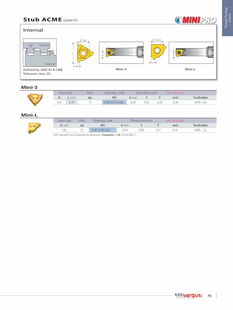
Y
IC 5.0 L
Y
L
IC 6.0
h
29°
F F
75
Thre
ad T
urni
ng
Inse
rts
Mini-3 Mini-LDefined by: ANSI B1.8:1988Tolerance class: 2G
External
Internal
Internal
Stub ACME (con't)
Mini-LInsert Size Pitch Ordering Code Dimensions inch Min. Bore dia.
IC mm tpi RH h min Y F inch Toolholder5.0L 12 5LIR12STACME... 0.03 0.05 0.17 0.31 .NVR... -5L
Left Handed Tool Supplied by Request. (Example: 6.0IL12STACME...)
Mini-3Insert Size Pitch Ordering Code Dimensions inch Min. Bore dia.
IC L inch tpi RH h min Y F inch Toolholder6.0 0.39 12 6.0IR12STACME... 0.03 0.05 0.20 0.39 .NVR..-6.0

L
XY
IC
R 0.18042PR 0.15011P
5/16P
h60°
maxmin
76
Thre
ad T
urni
ng
Inse
rts
StandardDefined by: MIL-S-8879CTolerance class: 3A/3B
External
Internal
External
UNJ - UNJC, UNJF, UNJEF, UNJS
StandardInsert Size Pitch Ordering Code Dimensions inch Anvil
IC L inch tpi RH LH h min X Y RH LH Toolholder
1/4" 0.43
48 2ER48UNJ... 2EL48UNJ... 0.012 0.02 0.02
- - NL..-2 (LH)
44 2ER44UNJ... 2EL44UNJ... 0.013 0.02 0.0240 2ER40UNJ... 2EL40UNJ... 0.015 0.02 0.0236 2ER36UNJ... 2EL36UNJ... 0.016 0.02 0.0232 2ER32UNJ... 2EL32UNJ... 0.018 0.02 0.0328 2ER28UNJ... 2EL28UNJ... 0.020 0.03 0.0324 2ER24UNJ... 2EL24UNJ... 0.024 0.03 0.0320 2ER20UNJ... 2EL20UNJ... 0.029 0.03 0.0418 2ER18UNJ... 2EL18UNJ... 0.032 0.03 0.0416 2ER16UNJ... 2EL16UNJ... 0.036 0.04 0.0414 2ER14UNJ... 2EL14UNJ... 0.041 0.04 0.05
3/8” 0.63
48 3ER48UNJ... 3EL48UNJ... 0.012 0.02 0.02
YE3 YI3 AL..-3 (LH)
44 3ER44UNJ... 3EL44UNJ... 0.013 0.02 0.0240 3ER40UNJ... 3EL40UNJ... 0.015 0.02 0.0236 3ER36UNJ... 3EL36UNJ... 0.016 0.02 0.0232 3ER32UNJ... 3EL32UNJ... 0.018 0.02 0.0328 3ER28UNJ... 3EL28UNJ... 0.020 0.03 0.0324 3ER24UNJ... 3EL24UNJ... 0.024 0.03 0.0320 3ER20UNJ... 3EL20UNJ... 0.029 0.03 0.0418 3ER18UNJ... 3EL18UNJ... 0.032 0.03 0.0416 3ER16UNJ... 3EL16UNJ... 0.036 0.04 0.0414 3ER14UNJ... 3EL14UNJ... 0.041 0.04 0.0513 3ER13UNJ... 3EL13UNJ... 0.044 0.04 0.0512 3ER12UNJ... 3EL12UNJ... 0.048 0.04 0.0511 3ER11UNJ... 3EL11UNJ... 0.052 0.05 0.0610 3ER10UNJ... 3EL10UNJ... 0.058 0.05 0.069 3ER9UNJ... 3EL9UNJ... 0.064 0.05 0.078 3ER8UNJ... 3EL8UNJ... 0.072 0.05 0.06
Continued on next page
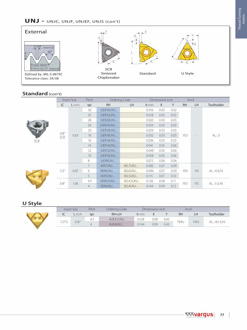
IC
L
Y
X
L
XY
IC 0.18042PR
R 0.15011P
5/16P
h60°
maxmin
X
L
IC
Y
77
Thre
ad T
urni
ng
Inse
rts
Defined by: MIL-S-8879CTolerance class: 3A/3B
External
Internal
External
UNJ - UNJC, UNJF, UNJEF, UNJS (con't)
U StyleSCB
SinteredChipbreaker
Standard
SCB
U StyleInsert Size Pitch Ordering Code Dimensions inch Anvil
IC L inch tpi RH+LH h min X Y RH LH Toolholder
1/2”U 0.874.5 4UE4.5UNJ... 0.128 0.08 0.43
YE4U YI4U AL..-4U (LH)4 4UE4UNJ... 0.144 0.09 0.43
Standard (con’t)
Insert Size Pitch Ordering Code Dimensions inch AnvilIC L inch tpi RH LH h min X Y RH LH Toolholder
3/8”SCB 0.63
36 3JER36UNJ... 0.016 0.05 0.02
YE3 - AL..-3
32 3JER32UNJ... 0.018 0.05 0.0228 3JER28UNJ... 0.020 0.03 0.0324 3JER24UNJ... 0.024 0.03 0.0320 3JER20UNJ... 0.029 0.03 0.0318 3JER18UNJ... 0.032 0.03 0.0316 3JER16UNJ... 0.036 0.03 0.0314 3JER14UNJ... 0.041 0.05 0.0612 3JER12UNJ... 0.048 0.05 0.0610 3JER10UNJ... 0.058 0.05 0.068 3JER8UNJ... 0.072 0.06 0.06
1/2” 0.877 4ER7UNJ... 4EL7UNJ... 0.082 0.07 0.09
YE4 YI4 AL..-4 (LH)6 4ER6UNJ... 4EL6UNJ... 0.096 0.07 0.095 4ER5UNJ... 4EL5UNJ... 0.115 0.07 0.10
5/8” 1.064.5 5ER4.5UNJ... 5EL4.5UNJ... 0.128 0.08 0.11
YE5 YI5 AL..-5 (LH)4 5ER4UNJ... 5EL4UNJ... 0.144 0.09 0.12

R 0.18042PR 0.15011P
5/16P
h60°
maxmin
L
XY
IC
X
L
IC
Y
78
Thre
ad T
urni
ng
Inse
rts
Defined by: MIL-S-8879CTolerance class: 3A/3B
External
Internal
Internal
UNJ - UNJC, UNJF, UNJEF, UNJS (con't)
SCBSintered
ChipbreakerStandard
SCB
StandardInsert Size Pitch Ordering Code Dimensions inch Anvil
IC L inch tpi RH LH h min X Y RH LH Toolholder
1/4" 0.43
48 2IR48UNJ... 2IL48UNJ... 0.011 0.02 0.02
- - NVR..-2 (LH)
44 2IR44UNJ... 2IL44UNJ... 0.012 0.02 0.0240 2IR40UNJ... 2IL40UNJ... 0.013 0.02 0.0236 2IR36UNJ... 2IL36UNJ... 0.015 0.02 0.0232 2IR32UNJ... 2IL32UNJ... 0.017 0.02 0.0328 2IR28UNJ... 2IL28UNJ... 0.019 0.03 0.0324 2IR24UNJ... 2IL24UNJ... 0.022 0.03 0.0320 2IR20UNJ... 2IL20UNJ... 0.026 0.03 0.0418 2IR18UNJ... 2IL18UNJ... 0.029 0.03 0.0416 2IR16UNJ... 2IL16UNJ... 0.033 0.04 0.0414 2IR14UNJ... 2IL14UNJ... 0.037 0.04 0.05
1/4”SCB 0.43
36 2JIR36UNJ... 0.015 0.04 0.02
- - NVR..-2
32 2JIR32UNJ... 0.017 0.05 0.0228 2JIR28UNJ... 0.019 0.02 0.0324 2JIR24UNJ... 0.022 0.02 0.0320 2JIR20UNJ... 0.026 0.02 0.0318 2JIR18UNJ... 0.029 0.02 0.0316 2JIR16UNJ... 0.033 0.02 0.0314 2JIR14UNJ... 0.037 0.02 0.03
Continued on next page

R 0.18042PR 0.15011P
5/16P
h60°
maxmin
L
XY
IC
X
L
IC
Y
79
Thre
ad T
urni
ng
Inse
rts
Defined by: MIL-S-8879CTolerance class: 3A/3B
External
Internal
Internal
UNJ - UNJC, UNJF, UNJEF, UNJS (con't)
SCBSintered
Chipbreaker
Standard
SCB
Standard (con’t)
Insert Size Pitch Ordering Code Dimensions inch AnvilIC L inch tpi RH LH h min X Y RH LH Toolholder
3/8” 0.63
48 3IR48UNJ... 3IL48UNJ... 0.011 0.02 0.02
YI3 YE3 AVR..-3 (LH)
44 3IR44UNJ... 3IL44UNJ... 0.012 0.02 0.0240 3IR40UNJ... 3IL40UNJ... 0.013 0.02 0.0236 3IR36UNJ... 3IL36UNJ... 0.015 0.02 0.0232 3IR32UNJ... 3IL32UNJ... 0.017 0.02 0.0328 3IR28UNJ... 3IL28UNJ... 0.019 0.03 0.0324 3IR24UNJ... 3IL24UNJ... 0.022 0.03 0.0320 3IR20UNJ... 3IL20UNJ... 0.026 0.03 0.0418 3IR18UNJ... 3IL18UNJ... 0.029 0.03 0.0416 3IR16UNJ... 3IL16UNJ... 0.033 0.04 0.0414 3IR14UNJ... 3IL14UNJ... 0.037 0.04 0.0513 3IR13UNJ... 3IL13UNJ... 0.040 0.04 0.0512 3IR12UNJ... 3IL12UNJ... 0.044 0.04 0.0511 3IR11UNJ... 3IL11UNJ... 0.048 0.05 0.0610 3IR10UNJ... 3IL10UNJ... 0.052 0.05 0.069 3IR9UNJ... 3IL9UNJ... 0.058 0.05 0.078 3IR8UNJ... 3IL8UNJ... 0.065 0.05 0.0628 3JIR28UNJ... 0.019 0.02 0.03
YI3 - AVR..-3
24 3JIR24UNJ... 0.022 0.02 0.0320 3JIR20UNJ... 0.026 0.02 0.03
3/8”SCB 0.63
18 3JIR18UNJ... 0.029 0.02 0.0316 3JIR16UNJ... 0.033 0.02 0.0314 3JIR14UNJ... 0.037 0.04 0.0612 3JIR12UNJ... 0.044 0.04 0.0610 3JIR10UNJ... 0.052 0.04 0.068 3JIR8UNJ... 0.065 0.04 0.06
1/2” 0.877 4IR7UNJ... 4IL7UNJ... 0.075 0.07 0.09
YI4 YE4 AVR..-4 (LH)6 4IR6UNJ... 4IL6UNJ... 0.087 0.07 0.095 4IR5UNJ... 4IL5UNJ... 0.105 0.07 0.10
5/8” 1.064.5 5IR4.5UNJ... 5IL4.5UNJ... 0.116 0.08 0.11
YI5 YE5 AVR..-5 (LH)4 5IR4UNJ... 5IL4UNJ... 0.131 0.09 0.09

IC
L
Y
X
R 0.18042PR 0.15011P
5/16P
h60°
maxmin
R 0.18042PR 0.15011P
5/16P
h60°
maxmin Y
L
IC 6.0
Y
IC 5.0 L
F F
80
Thre
ad T
urni
ng
Inse
rts
Mini-3 Mini-LDefined by: MIL-S-8879CTolerance class: 3A/3B
External
Internal
Internal
UNJ - UNJC, UNJF, UNJEF, UNJS (con't)
Defined by: MIL-S-8879CTolerance class: 3A/3B
External
Internal
Internal
UNJ - UNJC, UNJF, UNJEF, UNJS (con't)
U Style
Mini-LInsert Size Pitch Ordering Code Dimensions inch Min. Bore dia.
IC mm tpi RH h min Y F inch Toolholder
5.0L
32 5LIR32UNJ... 0.017 0.02 0.15 0.30
.NVR... -5L
28 5LIR28UNJ... 0.019 0.02 0.16 0.3020 5LIR20UNJ... 0.026 0.04 0.17 0.3118 5LIR18UNJ... 0.029 0.04 0.17 0.3116 5LIR16UNJ... 0.033 0.04 0.17 0.3114 5LIR14UNJ... 0.037 0.04 0.18 0.31
Left Handed Tool Supplied by Request. (Example: 6.0IL20UNJ...)
Mini-3Insert Size Pitch Ordering Code Dimensions inch Min. Bore dia.
IC L inch tpi RH h min Y F inch Toolholder6.0 0.39 20 6.0IR20UNJ... 0.026 0.04 0.19 0.39 .NVR...-6.0
U StyleInsert Size Pitch Ordering Code Dimensions inch Anvil
IC L inch tpi RH+LH h min X Y RH LH Toolholder
1/2”U 0.874.5 4UI4.5UNJ... 0.116 0.08 0.43
YI4U YE4U AVR..-4U (LH)4 4UI4UNJ... 0.131 0.09 0.43

L
XY
IC
1/4P
1/8P
h
60°
LX
IC
T
Y
81
Thre
ad T
urni
ng
Inse
rts
Defined by: ISO 5855Tolerance class: 4h/6h-4H/5H
External
Internal
External
MJ
Slim ThroatExternal - Standard
Slim ThroatInsert Size Pitch Ordering Code Dimensions inch
IC L inch mm RH LH h min X Y T Toolholder
1/4”V 0.43
0.7 2VER0.7MJ 2VEL0.7MJ 0.016 0.03 0.10 0.13
NL..-2V (LH)
0.8 2VER0.8MJ 2VEL0.8MJ 0.017 0.03 0.10 0.130.9 2VER0.9MJ 2VEL0.9MJ 0.021 0.03 0.10 0.131.0 2VER1.0MJ 2VEL1.0MJ 0.023 0.03 0.10 0.131.25 2VER1.25MJ 2VEL1.25MJ 0.028 0.03 0.09 0.131.5 2VER1.5MJ 2VEL1.5MJ 0.034 0.03 0.09 0.13
StandardInsert Size Pitch Ordering Code Dimensions inch Anvil
IC L inch mm RH LH h min X Y RH LH Toolholder
1/4" 0.431.0 2ER1.0MJ... 2EL1.0MJ... 0.023 0.03 0.03
- - NL..-2 (LH)1.25 2ER1.25MJ... 2EL1.25MJ... 0.028 0.03 0.041.5 2ER1.5MJ... 2EL1.5MJ... 0.034 0.03 0.04
3/8” 0.63
0.7 3ER0.7MJ... 3EL0.7MJ... 0.016 0.02 0.02
YE3 YI3 AL..-3 (LH)
1.0 3ER1.0MJ... 3EL1.0MJ... 0.023 0.03 0.031.25 3ER1.25MJ... 3EL1.25MJ... 0.028 0.03 0.041.5 3ER1.5MJ... 3EL1.5MJ... 0.034 0.03 0.042.0 3ER2.0MJ... 3EL2.0MJ... 0.045 0.04 0.052.5 3ER2.5MJ... 3EL2.5MJ... 0.059 0.04 0.063.0 3ER3.0MJ... 3EL3.0MJ... 0.068 0.05 0.06
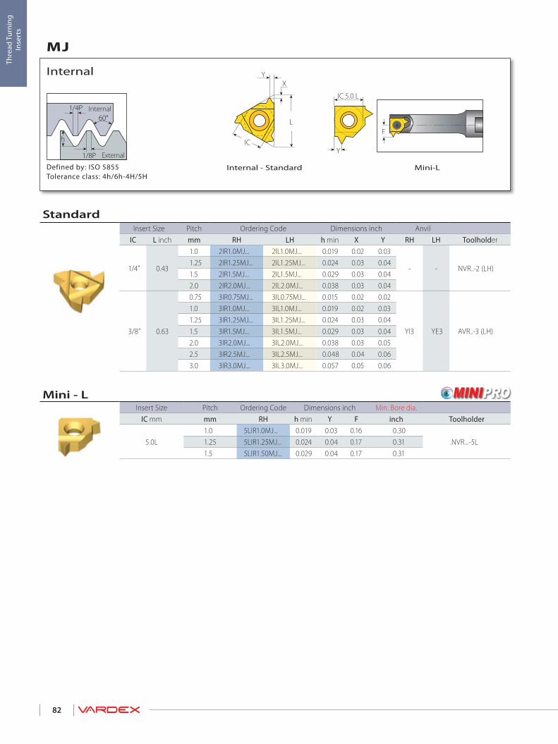
L
XY
IC
1/4P
1/8P
h
60°
Y
IC 5.0 L
F
82
Thre
ad T
urni
ng
Inse
rts
Defined by: ISO 5855Tolerance class: 4h/6h-4H/5H
External
Internal
Internal
MJ
Mini-LInternal - Standard
Mini - LInsert Size Pitch Ordering Code Dimensions inch Min. Bore dia.
IC mm mm RH h min Y F inch Toolholder
5.0L1.0 5LIR1.0MJ... 0.019 0.03 0.16 0.30
.NVR...-5L1.25 5LIR1.25MJ... 0.024 0.04 0.17 0.311.5 5LIR1.50MJ... 0.029 0.04 0.17 0.31
StandardInsert Size Pitch Ordering Code Dimensions inch Anvil
IC L inch mm RH LH h min X Y RH LH Toolholder
1/4" 0.43
1.0 2IR1.0MJ... 2IL1.0MJ... 0.019 0.02 0.03
- - NVR..-2 (LH)1.25 2IR1.25MJ... 2IL1.25MJ... 0.024 0.03 0.041.5 2IR1.5MJ... 2IL1.5MJ... 0.029 0.03 0.042.0 2IR2.0MJ... 2IL2.0MJ... 0.038 0.03 0.04
3/8” 0.63
0.75 3IR0.75MJ... 3IL0.75MJ... 0.015 0.02 0.02
YI3 YE3 AVR..-3 (LH)
1.0 3IR1.0MJ... 3IL1.0MJ... 0.019 0.02 0.031.25 3IR1.25MJ... 3IL1.25MJ... 0.024 0.03 0.041.5 3IR1.5MJ... 3IL1.5MJ... 0.029 0.03 0.042.0 3IR2.0MJ... 3IL2.0MJ... 0.038 0.03 0.052.5 3IR2.5MJ... 3IL2.5MJ... 0.048 0.04 0.063.0 3IR3.0MJ... 3IL3.0MJ... 0.057 0.05 0.06

LX
IC
Y
TIC
L
Y
X
L
XY
IC
45°7°
0.16316P
h
0.16316P
83
Thre
ad T
urni
ng
Inse
rts
Defined by: ANSI B1.9.1973Tolerance class: Class 2
External
Internal
External
American Buttress
V StyleU StyleStandard
V StyleInsert Size Pitch Ordering Code Dimensions inchIC L inch tpi RH LH h min X Y T Toolholder
5/8”V 1.064 5VER4ABUT... 5VEL4ABUT... 0.166 0.02 0.07 0.24 NL..-5V-6 (LH)3 5VER3ABUT... 5VEL3ABUT... 0.221 0.02 0.09 0.31 NL..-5V-8 (LH)2.5 5VER2.5ABUT... 5VEL2.5ABUT... 0.265 0.02 0.11 0.39 NL..-5V-10ABUT (LH)
U StyleInsert Size Pitch Ordering Code Dimensions inch AnvilIC L inch tpi RH LH h min X Y RH LH Toolholder
1/2”U 0.87 4 4UER4ABUT... 4UEL4ABUT... 0.166 0.09 0.39 YE4U-BUT4 YI4U-BUT4 AL..-4U (LH)5/8”U 1.06 3 5UER3ABUT... 5UEL3ABUT... 0.221 0.12 0.48 YE5U-BUT3 YI5U-BUT3 AL..-5U (LH)
StandardInsert Size Pitch Ordering Code Dimensions inch Anvil
IC L inch tpi RH LH h min X Y RH LH Toolholder
1/4" 0.4320 2ER20ABUT... 2EL20ABUT... 0.033 0.04 0.06
- - NL..-2 (LH)16 2ER16ABUT... 2EL16ABUT... 0.041 0.05 0.07
3/8” 0.63
20 3ER20ABUT... 3EL20ABUT... 0.033 0.04 0.06
YE3 YI3 AL..-3 (LH)16 3ER16ABUT... 3EL16ABUT... 0.041 0.05 0.0712 3ER12ABUT... 3EL12ABUT... 0.055 0.06 0.0810 3ER10ABUT... 3EL10ABUT... 0.066 0.06 0.09
1/2” 0.878 4ER8ABUT... 4EL8ABUT... 0.083 0.08 0.13
YE4 YI4 AL..-4 (LH)6 4ER6ABUT... 4EL6ABUT... 0.110 0.09 0.14
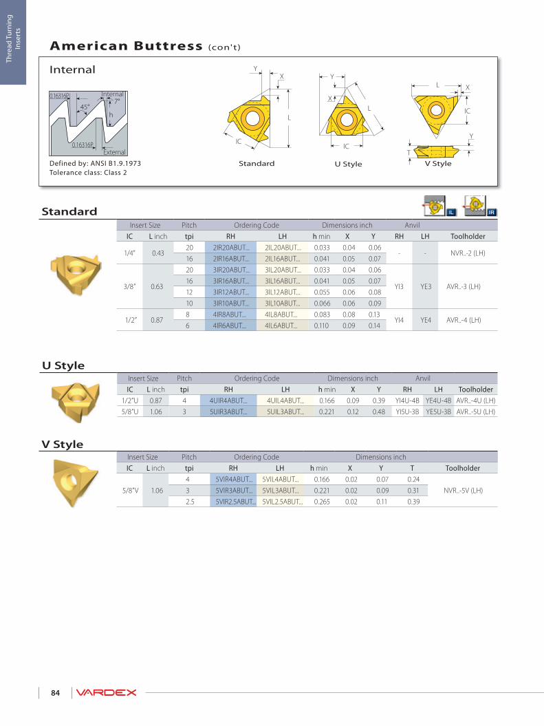
45°7°
0.16316P
h
0.16316P
L
XY
ICIC
L
Y
X
L X
IC
Y
T
84
Thre
ad T
urni
ng
Inse
rts
Defined by: ANSI B1.9.1973Tolerance class: Class 2
External
Internal
Internal
American Buttress (con't)
V StyleU StyleStandard
V StyleInsert Size Pitch Ordering Code Dimensions inchIC L inch tpi RH LH h min X Y T Toolholder
5/8”V 1.064 5VIR4ABUT... 5VIL4ABUT... 0.166 0.02 0.07 0.24
NVR..-5V (LH)3 5VIR3ABUT... 5VIL3ABUT... 0.221 0.02 0.09 0.312.5 5VIR2.5ABUT... 5VIL2.5ABUT... 0.265 0.02 0.11 0.39
U StyleInsert Size Pitch Ordering Code Dimensions inch AnvilIC L inch tpi RH LH h min X Y RH LH Toolholder
1/2”U 0.87 4 4UIR4ABUT... 4UIL4ABUT... 0.166 0.09 0.39 YI4U-4B YE4U-4B AVR..-4U (LH)5/8”U 1.06 3 5UIR3ABUT... 5UIL3ABUT... 0.221 0.12 0.48 YI5U-3B YE5U-3B AVR..-5U (LH)
StandardInsert Size Pitch Ordering Code Dimensions inch Anvil
IC L inch tpi RH LH h min X Y RH LH Toolholder
1/4" 0.4320 2IR20ABUT... 2IL20ABUT... 0.033 0.04 0.06
- - NVR..-2 (LH)16 2IR16ABUT... 2IL16ABUT... 0.041 0.05 0.07
3/8” 0.63
20 3IR20ABUT... 3IL20ABUT... 0.033 0.04 0.06
YI3 YE3 AVR..-3 (LH)16 3IR16ABUT... 3IL16ABUT... 0.041 0.05 0.0712 3IR12ABUT... 3IL12ABUT... 0.055 0.06 0.0810 3IR10ABUT... 3IL10ABUT... 0.066 0.06 0.09
1/2” 0.878 4IR8ABUT... 4IL8ABUT... 0.083 0.08 0.13
YI4 YE4 AVR..-4 (LH)6 4IR6ABUT... 4IL6ABUT... 0.110 0.09 0.14

L
XY
IC
45°7°
0.2754P
h
0.2754P
L
XY
IC
45°7°
0.2754P
h
0.2754P
85
Thre
ad T
urni
ng
Inse
rts
Defined by: B.S. 1657: 1950Tolerance class: Medium Class
External
Internal
Internal
British Buttress
Standard
Defined by: B.S. 1657: 1950Tolerance class: Medium Class
External
Internal
External
British Buttress
Standard
StandardInsert Size Pitch Ordering Code Dimensions inch Anvil
IC L inch tpi RH LH h min X Y RH LH Toolholder
3/8” 0.63
16 3IR16BBUT... 3IL16BBUT... 0.031 0.04 0.06
YI3 YE3 AVR..-3 (LH)12 3IR12BBUT... 3IL12BBUT... 0.042 0.06 0.0810 3IR10BBUT... 3IL10BBUT... 0.050 0.06 0.098 3IR8BBUT... 3IL8BBUT... 0.063 0.06 0.10
1/2” 0.87 8 4IR8BBUT... 4IL8BBUT... 0.063 0.06 0.10 YI4 YE4 AVR..-4 (LH)
StandardInsert Size Pitch Ordering Code Dimensions inch Anvil
IC L inch tpi RH LH h min X Y RH LH Toolholder
3/8” 0.63
16 3ER16BBUT... 3EL16BBUT... 0.031 0.04 0.06
YE3 YI3 AL..-3 (LH)12 3ER12BBUT... 3EL12BBUT... 0.042 0.06 0.0810 3ER10BBUT... 3EL10BBUT... 0.050 0.06 0.098 3ER8BBUT... 3EL8BBUT... 0.063 0.06 0.10
1/2” 0.87 8 4ER8BBUT... 4EL8BBUT... 0.063 0.06 0.10 YE4 YI4 AL..-4 (LH)

L
XY
IC
L
XY
IC
30°3°
0.26384P
h
0.26384P
IC
L
Y
X
IC
L
Y
X
86
Thre
ad T
urni
ng
Inse
rts
Defined by: DIN 513Tolerance class: Medium Class
External
Internal
External / Internal
Metric Buttress (Sägengewinde)
Internal U Style
External U Style
Internal Standard
External Standard
U Style - InternalInsert Size Pitch Ordering Code Dimensions inch AnvilIC L inch mm RH LH h min X Y RH LH Toolholder
1/2”U 0.875 4UIR5.0SAGE... 4UIL5.0SAGE... 0.148 0.07 0.41 YI4U-5S YE4U-5S
AVR..-4U (LH)6 4UIR6.0SAGE... 4UIL6.0SAGE... 0.179 0.07 0.40 YI4U-6S YE4U-6S
Standard - InternalInsert Size Pitch Ordering Code Dimensions inch AnvilIC L inch mm RH LH h min X Y RH LH Toolholder
3/8” 0.63 2.0 3IR2.0SAGE... 3IL2.0SAGE... 0.059 0.06 0.09 YI3 YE3 AVR..-3 (LH)
1/2” 0.873.0 4IR3.0SAGE... 4IL3.0SAGE... 0.089 0.07 0.11
YI4 YE4 AVR..-4 (LH)4.0 4IR4.0SAGE... 4IL4.0SAGE... 0.122 0.08 0.13
5/8” 1.06 4.0 5IR4.0SAGE... 5IL4.0SAGE... 0.122 0.08 0.13 YI5 082/039 YE5 082/038 AVR..-5 (LH)
U Style - ExternalInsert Size Pitch Ordering Code Dimensions inch AnvilIC L inch mm RH LH h min X Y RH LH Toolholder
1/2”U 0.875 4UER5.0SAGE... 4UEL5.0SAGE... 0.174 0.05 0.41 YE4U-SAGE5 YI4U-SAGE5
AL..-4U (LH)6 4UER6.0SAGE... 4UEL6.0SAGE... 0.208 0.05 0.40 YE4U-SAGE6 YI4U-SAGE6
Standard - ExternalInsert Size Pitch Ordering Code Dimensions inch AnvilIC L inch mm RH LH h min X Y RH LH Toolholder
3/8” 0.63 2.0 3ER2.0SAGE... 3EL2.0SAGE... 0.069 0.06 0.08 YE3 YI3 AL..-3 (LH)
1/2” 0.872.0 4ER2.0SAGE... 4EL2.0SAGE... 0.069 0.06 0.08
YE4 YI4 AL..-4 (LH)3.0 4ER3.0SAGE... 4EL3.0SAGE... 0.102 0.07 0.104.0 4ER4.0SAGE... 4EL4.0SAGE... 0.140 0.07 0.12
5/8” 1.06 4.0 5ER4.0SAGE... 5EL4.0SAGE... 0.140 0.07 0.13 YE5 082/038 YI5 082/039 AL..-5 (LH)

L
XY
IC
L
XY
ICα
30° 30°
90°
hh
= arctg (IPF/24)α
87
Thre
ad T
urni
ng
Inse
rts
Defined by: API SPEC. 7:1990Tolerance class: Standard API
External
Internal
External / Internal
API
Internal - StandardExternal - Standard
Standard - InternalInsert Size Pitch Thread Taper Ordering Code Size Dimensions inch AnvilIC L inch tpi IPF RH h min X Y RH Toolholder
1/2" 0.87
4 V-0.038R 2 4IR4API382... NC23-NC50 0.122 0.08 0.11
YI4 AVR..-4 (LH)
4 V-0.038R 3 4IR4API383... NC56-NC77 0.121 0.08 0.114 V-0.050 2 4IR4API502... 6 5/8” REG 0.148 0.08 0.124 V-0.050 3 4IR4API503... 5 1/2”, 7 5/8”, 8 5/8” REG 0.147 0.08 0.115 V-0.040 3 4IR5API403... 2 3/8”-4 1/2” REG 0.118 0.07 0.106 V-0.055 1.5 4IR6API551... NC10-NC16 0.056 0.10 0.08
5/8” 1.06
4 V-0.038R 2 5IR4API382... NC23-NC50 0.122 0.08 0.11
YI5OIL AVR..-5 OIL (LH)4 V-0.038R 3 5IR4API383... NC56-NC77 0.121 0.08 0.114 V-0.050 2 5IR4API502... 6 5/8” REG 0.148 0.08 0.124 V-0.050 3 5IR4API503... 5 1/2”, 7 5/8”, 8 5/8” REG 0.147 0.08 0.125 V-0.040 3 5IR5API403... 2 3/8”-4 1/2” REG 0.118 0.07 0.11
Standard - ExternalInsert Size Pitch Thread Taper Ordering Code Size Dimensions inch AnvilIC L inch tpi IPF RH h min X Y RH Toolholder
1/2" 0.87
4 V-0.038R 2 4ER4API382... NC23-NC50 0.122 0.08 0.11
YE4 AL..-4 (LH)
4 V-0.038R 3 4ER4API383... NC56-NC77 0.121 0.08 0.114 V-0.050 2 4ER4API502... 6 5/8” REG 0.148 0.08 0.114 V-0.050 3 4ER4API503... 5 1/2”, 7 5/8”, 8 5/8” REG 0.147 0.08 0.115 V-0.040 3 4ER5API403... 2 3/8”-4 1/2” REG 0.118 0.07 0.106 V-0.055 1.5 4ER6API551... NC10-NC16 0.056 0.10 0.08
5/8” 1.06
4 V-0.038R 2 5ER4API382... NC23-NC50 0.122 0.08 0.11
YE5OIL AL..-5 OIL (LH)4 V-0.038R 3 5ER4API383... NC56-NC77 0.121 0.08 0.114 V-0.050 2 5ER4API502... 6 5/8” REG 0.148 0.08 0.124 V-0.050 3 5ER4API503... 5 1/2”, 7 5/8”, 8 5/8” REG 0.147 0.08 0.125 V-0.040 3 5ER5API403... 2 3/8”-4 1/2” REG 0.118 0.07 0.11
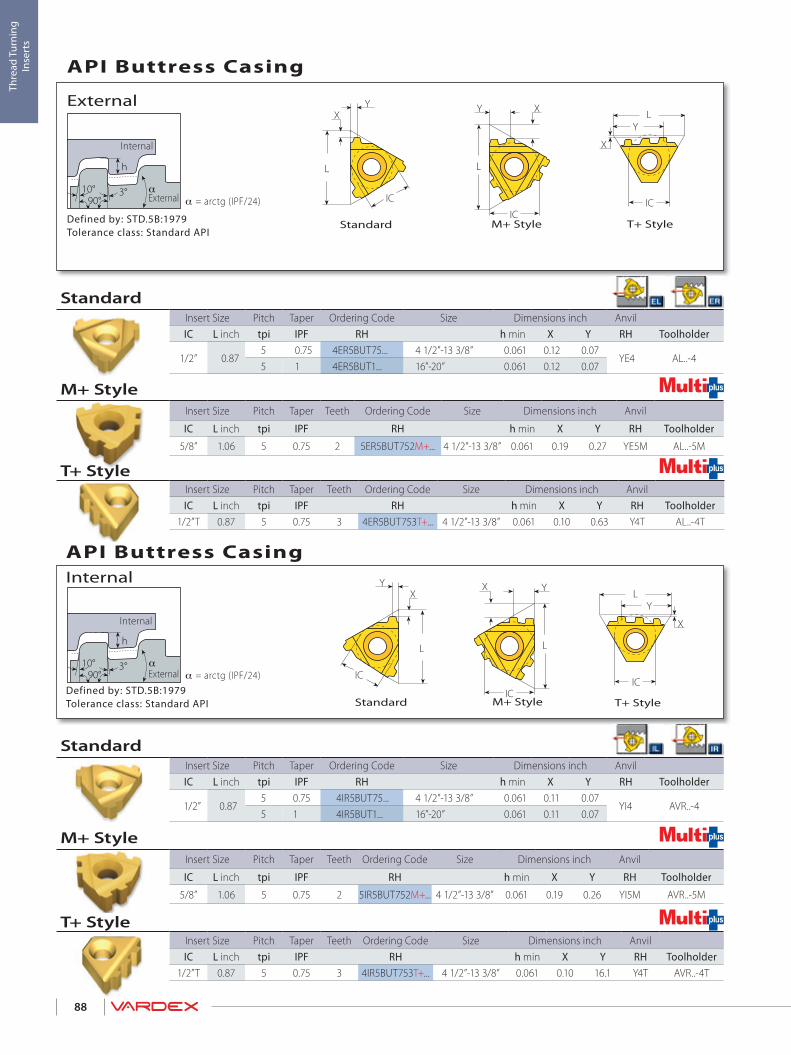
L
XY
IC
= 1/2 arctg (IPF/12)α
α90°
h
3°10°= arctg (IPF/24)α
L
IC
X
Y
L
XY
IC
L
XY
IC
L
IC
X
Y
= 1/2 arctg (IPF/12)α
α90°
h
3°10°= arctg (IPF/24)α
L
X Y
IC
88
Thre
ad T
urni
ng
Inse
rts
Defined by: STD.5B:1979Tolerance class: Standard API
External
Internal
Internal
API Buttress Casing
T+ StyleM+ Style Standard
Defined by: STD.5B:1979Tolerance class: Standard API
External
Internal
External
API Buttress Casing
T+ StyleM+ Style Standard
T+ StyleInsert Size Pitch Taper Teeth Ordering Code Size Dimensions inch AnvilIC L inch tpi IPF RH h min X Y RH Toolholder
1/2”T 0.87 5 0.75 3 4IR5BUT753T+... 4 1/2”-13 3/8” 0.061 0.10 16.1 Y4T AVR..-4T
StandardInsert Size Pitch Taper Ordering Code Size Dimensions inch AnvilIC L inch tpi IPF RH h min X Y RH Toolholder
1/2” 0.875 0.75 4IR5BUT75... 4 1/2”-13 3/8” 0.061 0.11 0.07
YI4 AVR..-4 5 1 4IR5BUT1... 16”-20” 0.061 0.11 0.07
StandardInsert Size Pitch Taper Ordering Code Size Dimensions inch AnvilIC L inch tpi IPF RH h min X Y RH Toolholder
1/2” 0.875 0.75 4ER5BUT75... 4 1/2”-13 3/8” 0.061 0.12 0.07
YE4 AL..-4 5 1 4ER5BUT1... 16”-20” 0.061 0.12 0.07
M+ StyleInsert Size Pitch Taper Teeth Ordering Code Size Dimensions inch Anvil
IC L inch tpi IPF RH h min X Y RH Toolholder
5/8” 1.06 5 0.75 2 5ER5BUT752M+... 4 1/2”-13 3/8” 0.061 0.19 0.27 YE5M AL..-5M
T+ StyleInsert Size Pitch Taper Teeth Ordering Code Size Dimensions inch AnvilIC L inch tpi IPF RH h min X Y RH Toolholder
1/2”T 0.87 5 0.75 3 4ER5BUT753T+... 4 1/2”-13 3/8” 0.061 0.10 0.63 Y4T AL..-4T
M+ StyleInsert Size Pitch Taper Teeth Ordering Code Size Dimensions inch Anvil
IC L inch tpi IPF RH h min X Y RH Toolholder
5/8” 1.06 5 0.75 2 5IR5BUT752M+... 4 1/2”-13 3/8” 0.061 0.19 0.26 YI5M AVR..-5M

L
X
Y
IC
L
IC
X
Y
L
XY
IC1°47'
30° 30°
90 °
h
X
L
IC
Y
89
Thre
ad T
urni
ng
Inse
rts
Defined by: API STD. 5B:1979Tolerance class: Standard API RD
External
Internal
External
API Round Casing & Tubing
T+ StyleSCB
SinteredChipbreaker
M+ Style Standard
SCB
T+ StyleInsert Size Pitch Teeth Ordering Code Dimensions inch Anvil
IC L inch tpi RH h min X Y RH Toolholder
1/2”T 0.87
10 6 4ER10APIRD6T+... 0.056 0.01 0.64
Y4T AL..-4T8 3 4ER8APIRD3T+... 0.071 0.01 0.56
8 5 4ER8APIRD5T+... 0.071 0.01 0.66
M+ StyleInsert Size Pitch Teeth Ordering Code Dimensions inch Anvil
IC L inch tpi RH h min X Y RH Toolholder
5/8” 1.0610 3 5ER10APIRD3M+... 0.056 0.15 0.25
YE5M AL..-5M8 2 5ER8APIRD2M+... 0.071 0.11 0.18
StandardInsert Size Pitch Ordering Code Dimensions inch Anvil
IC L inch tpi RH h min X Y RH Toolholder
3/8” 0.6310 3ER10APIRD... 0.056 0.05 0.06
YE3 AL..-38 3ER8APIRD... 0.071 0.05 0.06
3/8”SCB 0.63
10 3JER10APIRD... 0.056 0.05 0.06YE3 AL..-3
8 3JER8APIRD... 0.071 0.05 0.06

L
XY
IC
L
IC
X
Y
L
Y
X
IC
L
X
Y
IC1°47'
30° 30°
90°
h
X
L
IC
Y
90
Thre
ad T
urni
ng
Inse
rts
Defined by: API STD. 5B:1979Tolerance class: Standard API RD
External
Internal
Internal
API Round Casing & Tubing (con't)
Z+ Style T+ StyleSCB
SinteredChipbreaker
M+ Style Standard
SCB
T+ StyleInsert Size Pitch Teeth Ordering Code Dimensions inch AnvilIC L inch tpi RH h min X Y RH Toolholder
1/2”T 0.87
10 6 4IR10APIRD6T+... 0.056 0.01 0.66
Y4T AVR..-4T8 3 4IR8APIRD3T+... 0.071 0.01 0.56
8 5 4IR8APIRD5T+... 0.071 0.01 0.66
Z+ StyleInsert Size Pitch Teeth Ordering Code Dimensions inch Anvil
IC L inch tpi RH h min X Y RH Toolholder
1/2” 0.87 8 2 4IR8APIRD2Z+... 0.071 0.15 0.38 YI4Z AVR..-4Z
StandardInsert Size Pitch Ordering Code Dimensions inch AnvilIC L inch tpi RH h min X Y RH Toolholder
3/8” 0.6310 3IR10APIRD... 0.056 0.05 0.06
YI3 AVR..-38 3IR8APIRD... 0.071 0.05 0.06
3/8”SCB 0.63
10 3JIR10APIRD... 0.056 0.05 0.06YI3 AVR..-3
8 3JIR8APIRD... 0.071 0.05 0.06
M+ StyleInsert Size Pitch Teeth Ordering Code Dimensions inch Anvil
IC L inch tpi RH h min X Y RH Toolholder
1/2” 0.8710 2 4IR10APIRD2M+... 0.056 0.09 0.15
YI4M AVR..-48 2 4IR8APIRD2M+... 0.071 0.11 0.18
5/8” 1.0610 3 5IR10APIRD3M+... 0.056 0.15 0.25
YI5M AVR..-5M8 2 5IR8APIRD2M+... 0.071 0.11 0.18

L
XY
IC
L
XY
IC
= 1/2 arctg (IPF/12)
90°
h
3°10° α= arctg (IPF/24)α
91
Thre
ad T
urni
ng
Inse
rts
Defined by: VAMTolerance class: Standard VAM
External
Internal
External / Internal
VAM
Internal - StandardExternal - Standard
Standard - InternalInsert Size Pitch Taper Ordering Code Size Dimensions inch AnvilIC L inch tpi IPF RH h min X Y RH Toolholder3/8” 0.63 8 0.75 3IR8VAM... 2 3/8”, 2 7/8” 0.038 0.07 0.07 YI3 AVR..-3
1/2” 0.876 0.75 4IR6VAM... 3 1/2” 0.038 0.10 0.10
YI4 AVR..-45 0.75 4IR5VAM... 5”-9 5/8” 0.061 0.09 0.10
Standard - ExternalInsert Size Pitch Taper Ordering Code Size Dimensions inch AnvilIC L inch tpi IPF RH h min X Y RH Toolholder3/8” 0.63 8 0.75 3ER8VAM... 2 3/8”, 2 7/8” 0.038 0.07 0.07 YE3 AL..-3
1/2” 0.876 0.75 4ER6VAM... 3 1/2” 0.038 0.09 0.09
YE4 AL..-45 0.75 4ER5VAM... 5”-9 5/8” 0.061 0.09 0.11

L
XY
IC
L
XY
IC
6° 6°
hα90°
h
α = arctg (IPF/24)
92
Thre
ad T
urni
ng
Inse
rts
Defined by: API STD,5B:1979Tolerance class: Standard
External
Internal
External / Internal
EL-Extreme Line
Internal - StandardExternal - Standard
Standard - InternalInsert Size Pitch Taper Ordering Code Connection No. or Size Dimensions inch AnvilIC L inch tpi IPF RH h min X Y RH Toolholder
1/2" 0.876 1.5 4IR6EL15... 5”-7 5/8” 0.055 0.07 0.07
YI4 AVR..-4 (LH)5 1.25 4IR5EL125... 8 5/8”-10 3/4” 0.075 0.09 0.09
Standard - ExternalInsert Size Pitch Taper Ordering Code Connection No. or Size Dimensions inch AnvilIC L inch tpi IPF RH h min X Y RH Toolholder
1/2" 0.876 1.5 4ER6EL15... 5”-7 5/8” 0.048 0.07 0.07
YE4 AL..-4 (LH)5 1.25 4ER5EL125... 8 5/8”-10 3/4” 0.067 0.09 0.09

IC
L
Y
X45°
90°
45°
h
h
= arctg (IPF/24)α
93
Thre
ad T
urni
ng
Inse
rts
Defined by: API STD,5B:1979Tolerance class: Standard
External
Internal
External / Internal
Hughes H-90
U Style
U Style - InternalInsert Size Pitch Taper Ordering Code Size Dimensions inch Anvil
IC L inch tpi IPF RH h min X Y RH Toolholder
1/2” U 0.873.5 2 4UIR3.5H902... 3 1/2”-6 5/8” 0.098 0.17 0.43
YI4U-H90 AVR..-4U (LH)3.5 3 4UIR3.5H903... 7”-8 5/8” 0.098 0.17 0.43
5/8” U 1.06 3 1.25* 5UIR3H90SL... 2 3/8”-3 1/2” 0.088 0.22 0.54 YI5U-H90 AVR..-5U (LH) * H-90 Slimline
U Style - ExternalInsert Size Pitch Taper Ordering Code Size Dimensions inch AnvilIC L inch tpi IPF RH h min X Y RH Toolholder
1/2” U 0.873.5 2 4UER3.5H902... 3 1/2”-6 5/8” 0.098 0.17 0.43
YE4U-H90 AL..-4U (LH)3.5 3 4UER3.5H903... 7”-8 5/8” 0.098 0.17 0.43
5/8” U 1.06 3 1.25* 5UER3H90SL... 2 3/8”-3 1/2” 0.088 0.22 0.54 YE5U-H90 AL..-5U (LH) * H-90 Slimline

L
XY
IC
R0.107P
R0.107P
h
80°
L
XY
IC
94
Thre
ad T
urni
ng
Inse
rts
Defined by: DIN 40430Tolerance class: Standard
External
Internal
External / Internal
Pg
Standard InternalStandard External
Standard - InternalInsert Size Pitch Thread Ordering Code Dimensions inch AnvilIC L inch tpi RH LH h min X Y RH LH Toolholder
1/4" 0.4320 Pg7 2IR20PG... 2IL20PG... 0.025 0.03 0.04
- - NVR..-2 (LH)18 Pg9/11/13.5/16 2IR18PG... 2IL18PG... 0.026 0.03 0.0416 Pg21/29/36/42/48 2IR16PG... 2IL16PG... 0.030 0.04 0.04
3/8” 0.6320 Pg7 3IR20PG... 3IL20PG... 0.025 0.03 0.04
YI3 YE3 AVR..-3 (LH)18 Pg11/13.5/16 3IR18PG... 3IL18PG... 0.026 0.03 0.0416 Pg21/29/36/42/48 3IR16PG... 3IL16PG... 0.030 0.03 0.04
Standard - ExternalInsert Size Pitch Thread Ordering Code Dimensions inch AnvilIC L inch tpi RH LH h min X Y RH LH Toolholder
1/4" 0.4320 Pg7 2ER20PG... 2EL20PG... 0.024 0.03 0.04
- - NL..-2 (LH)18 Pg9/11/13.5/16 2ER18PG... 2EL18PG... 0.026 0.03 0.0416 Pg21/29/36/42/48 2ER16PG... 2EL16PG... 0.030 0.04 0.04
3/8” 0.6320 Pg7 3ER20PG... 3EL20PG... 0.024 0.03 0.04
YE3 YI3 AL..-3 (LH)18 Pg9/11/13.5/16 3ER18PG... 3EL18PG... 0.026 0.03 0.0416 Pg21/29/36/42/48 3ER16PG... 3EL16PG... 0.030 0.04 0.04
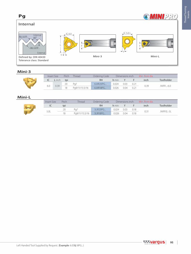
R0.107P
R0.107P
h
80°
Y
IC 5.0 L
Y
L
IC 6.0
F F
95
Thre
ad T
urni
ng
Inse
rts
Mini-LMini-3Defined by: DIN 40430Tolerance class: Standard
External
Internal
Internal
Pg
Left Handed Tool Supplied by Request. (Example: 6.0SIL18PG...)
Mini-LInsert Size Pitch Thread Ordering Code Dimensions inch Min. Bore dia.
IC tpi RH h min Y F inch Toolholder
5.0L20 Pg7 5LIR20PG... 0.024 0.03 0.18
0.31 .NVR10..-5L18 Pg9/11/13.5/16 5LIR18PG... 0.026 0.04 0.18
Mini-3Insert Size Pitch Thread Ordering Code Dimensions inch Min. Bore dia.IC L inch tpi RH h min Y F inch Toolholder
6.0 0.3920 Pg7 6.0IR20PG... 0.024 0.03 0.21
0.39 .NVR1..-6.018 Pg9/11/13.5/16 6.0IR18PG... 0.026 0.04 0.21

96
Thre
ad T
urni
ng
Inse
rts

97
Thread Turning> Toolholders
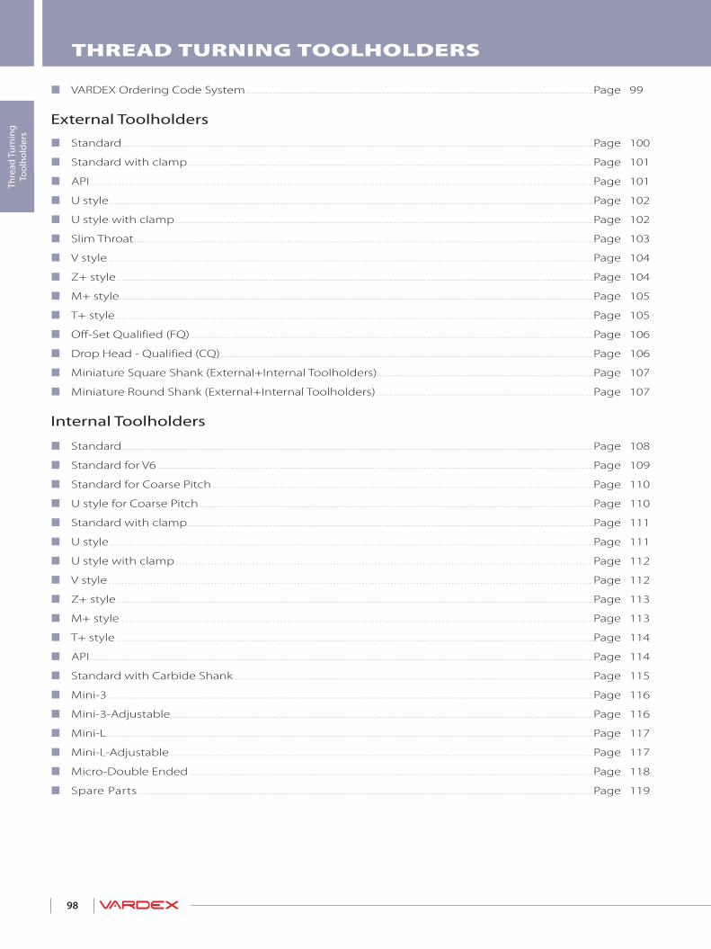
98
Thre
ad T
urni
ng
Tool
hold
ers
THREAD TURNING TOOLHOLDERS
VARDEX Ordering Code System ...............................................................................................................................................Page 99
External Toolholders
Standard ..................................................................................................................................................................................................Page 100
Standard with clamp .......................................................................................................................................................................Page 101
API ...............................................................................................................................................................................................................Page 101
U style .......................................................................................................................................................................................................Page 102
U style with clamp ............................................................................................................................................................................Page 102
Slim Throat .............................................................................................................................................................................................Page 103
V style .......................................................................................................................................................................................................Page 104
Z+ style ....................................................................................................................................................................................................Page 104
M+ style...................................................................................................................................................................................................Page 105
T+ style ....................................................................................................................................................................................................Page 105
Off-Set Qualified (FQ) ......................................................................................................................................................................Page 106
Drop Head - Qualified (CQ) .........................................................................................................................................................Page 106
Miniature Square Shank (External+Internal Toolholders) .........................................................................................Page 107
Miniature Round Shank (External+Internal Toolholders) .........................................................................................Page 107
Internal Toolholders
Standard ..................................................................................................................................................................................................Page 108
Standard for V6 ...................................................................................................................................................................................Page 109
Standard for Coarse Pitch .............................................................................................................................................................Page 110
U style for Coarse Pitch ..................................................................................................................................................................Page 110
Standard with clamp .......................................................................................................................................................................Page 111
U style .......................................................................................................................................................................................................Page 111
U style with clamp .... . . . . . . . . . . . . . . . . . . . . . . . . . . . . . . . . . . . . . . . . . . . . . . . . . . . . . . . . . . . . . . . . . . . . . . . . . . . . . . . . . . . . . . . . . . . . . . . . . . . . . . . . . . . . . . . . . . . . . . . . . . . . . . Page 112
V style ... . . . . . . . . . . . . . . . . . . . . . . . . . . . . . . . . . . . . . . . . . . . . . . . . . . . . . . . . . . . . . . . . . . . . . . . . . . . . . . . . . . . . . . . . . . . . . . . . . . . . . . . . . . . . . . . . . . . . . . . . . . . . . . . . . . . . . . . . . . . . . . . . . . . . Page 112
Z+ style ....................................................................................................................................................................................................Page 113
M+ style...................................................................................................................................................................................................Page 113
T+ style ....................................................................................................................................................................................................Page 114
API ...............................................................................................................................................................................................................Page 114
Standard with Carbide Shank ....................................................................................................................................................Page 115
Mini-3 ........................................................................................................................................................................................................Page 116
Mini-3-Adjustable..............................................................................................................................................................................Page 116
Mini-L ........................................................................................................................................................................................................Page 117
Mini-L-Adjustable ..............................................................................................................................................................................Page 117
Micro-Double Ended ......................................................................................................................................................................Page 118
Spare Parts ...........................................................................................................................................................................................Page 119

99
T+ Z+ M+
U V
Thre
ad T
urni
ng
Tool
hold
ers
Internal Toolholders
Micro & Adjustable Toolholders (Sleeves)
Vardex Ordering Code SystemExternal Toolholders
4 - Holder Dia.050, 0625, 075
3 - CoolingC - Coolant Channel
5 - Holder Bore Size [mm]
Micro Size3, 4, 6, 8, 10Adjustable Holders (for Mini)6.28
1- Holder Shape
S - Sleeve (Double Ended)
2 - Holder Type
V - Adjustable Holders for MiniM - Micro (Double Ended)
35
-06254
C3
M2
S1
12 - Serial No.157/... (Coarse Pitch Holder)
5 - Shank front Dia
0375, 050, 0625, 075, 100, 125, 150, 200, 2506.2 (Mini Adjust)8.0 (Mini Adjust)
11 - RH/LH Holder
None - Right HandLH - Left Hand
10 -Oil Field OIL - For API Inserts
9 - Clamping C - with Clamp
4 - CoolingC - With Coolant Channel
3 - Tool TypeVR - Internal Round shank
6 - Holder Length
(Mini Holders)U - Ultra ShortS - ShortM - MediumL - LongT - Adjustable
2 - AnvilA - Anvil requiredN - No Anvil requiredO - Miniature holder
8- Insert style
UVTMZLV6
7- Insert Size
4.0K - IC4.0 mm5L - IC5.0L mm6.0 - IC6.0 mm2 - IC1/4"3 - IC3/8"4 - IC1/2"5 - IC5/8"
1- Shank TypeB - Anti Vibration SystemC - Carbide ShankS - Mini Holders
- 376 12
0755 11
C4 10
VR3 9
A2 8
C1
4 - Insert Size2 - IC1/4"3 - IC3/8"4 - IC1/2"5 - IC5/8"
9 - RH/LH HolderNone - Right HandLH - Left Hand
7 - Insert Width [mm](for IC5/8"V)6, 8, 10
3 - Shank Square031, 3/8, 050, 0625, 075, 100, 125, 150, 200
8 - Tool TypeCQ - Drop HeadFQ - Off-SetOil - For API Inserts
6 - ClampingC - with Clamping
2 - Holder Style
L - ExternalV - Miniature Square ShankVR - Miniature Round Shank
5 - Insert Style
1- Anvil
A - Anvil requiredN - No Anvil requiredO - Miniature holder
987C6
U5
44
-1253
L2
A1

100
BF
L2L1
HH1
External Toolholders
The AL..-3 holders are supplied with standard anvil (see spare parts table below).For V6, please use the V6 anvil YE3-6C. For more info see page 127.
The above toolholders are for RH inserts. For LH inserts, add LH to the toolholder’s ordering code. (Example AL075-3 LH).
Standard Spare Parts
Insert Size Ordering Code EDP No. Dimensions inch
IC RH H=H1=B F L1 L2 Insert Screw Anvil Screw Torx Key Anvil RH Anvil LH1/4” NL031-2 66214 0.31 0.43 5.37 0.69 SN2T - K2T - -
3/8”
NL050-3 66220 0.50 0.63 3.27 0.87 SA3T - K3T - -AL3/8-3 66091 0.37 0.63 2.45 0.76
SA3T SY3T K3T YE3 YI3
AL050-3 66000 0.50 0.63 3.27 0.87AL0625-3 66005 0.63 0.63 5.00 1.02AL075-3 66007 0.75 0.75 5.00 1.02AL100-3 66016 1.00 1.00 6.00 1.20AL125-3 66036 1.25 1.25 7.00 1.18
1/2”AL100-4 66024 1.00 1.00 6.00 1.42
SA4T SY4T K4T YE4 YI4AL125-4 66042 1.25 1.25 7.00 1.42AL150-4 66066 1.50 1.50 8.00 1.42
5/8”
AL100-5 66034 1.00 1.25 6.00 1.57
SA5T SY5T K5T YE5 YI5AL125-5 66051 1.25 1.25 7.00 1.57AL150-5 66073 1.50 1.50 8.00 1.57AL200-5 66085 2.00 2.00 10.00 1.57
The above toolholders have a 1.5° helix angle. For other helix angles, see page 127.Toolholders with prefix “N” cannot be used with an anvil.
Thre
ad T
urni
ng
Tool
hold
ers

101
BF
L2L 1
HH1
BF
L 2L 1
HH1
External Toolholders
External Toolholders
The AL..-3 holders are supplied with standard anvil (see spare parts table below).For V6, please use the V6 anvil YE3-6C. For more info see page 127.
The above toolholders are for RH inserts. For LH inserts, add LH to the toolholder’s ordering code. (Example AL075-3C LH).The above toolholders have a 1.5° helix angle. For other helix angles, see page 127.
Standard for API Spare Parts
Insert Size Ordering Code EDP No. Thread Form Connection no. or size Dimensions inch
IC RH H=H1=B=F L1 L2 Insert Screw Anvil Screw Torx Key Anvil RH Anvil LH
5/8”AL125-5OIL 66058 V0.038R V0.050 NC23-NC77 all sizes 1.25 7.00 1.60
SA5T SY5T K5T YE5OIL YI5OILAL150-5OIL 66075 V0.038R V0.050 NC23-NC77 all sizes 1.50 8.00 1.60
Standard with Clamp(Dual System, Screw or Clamp) Spare Parts
Insert Size Ordering Code EDP No. Dimensions inch
IC RH H=H1=B F L1 L2 Insert Screw Anvil Screw Clamp Torx Key Anvil RH Anvil LH
3/8”AL075-3C 66008 0.75 0.75 5.00 1.20AL100-3C 66017 1.00 1.00 6.00 1.20AL125-3C 66031 1.25 1.25 7.00 1.20
1/2”AL100-4C 66330 1.00 1.00 6.00 1.42
SA4T SY4T C4 K4T YE4 YI4AL125-4C 66222 1.25 1.25 7.00 1.42AL150-4C 66223 1.50 1.50 8.00 1.42
5/8”
AL100-5C 66327 1.00 1.25 6.00 1.57
SA5T SY5T C5 K5T YE5 YI5AL125-5C 66224 1.25 1.25 7.00 1.57AL150-5C 66225 1.50 1.50 8.00 1.57AL200-5C 66230 2.00 2.00 10.00 1.57
Thre
ad T
urni
ng
Tool
hold
ers

102
BF
L 2L1
HH1
BF
L2L1
HH1
Thre
ad T
urni
ng
Tool
hold
ers
External Toolholders
External Toolholders
The above toolholders are for RH inserts. For LH inserts, add LH to the toolholder’s ordering code. (Example AL100-4U LH)All U Style Toolholders have a 1.5° helix angle. For other helix angles see page 127.
U Style with Clamp(Dual System, Screw or Clamp) Spare Parts
Insert Size Ordering Code EDP No. Dimensions inch
IC RH H=H1=B F L1 L2 Insert Screw Anvil Screw Clamp Torx Key Anvil RH Anvil LH
1/2”UAL125-4UC 66250 1.25 1.25 7.00 1.52
SA4T SY4T C4 K4T YE4U YI4UAL150-4UC 66251 1.50 1.50 8.00 1.52
5/8”UAL125-5UC 66252 1.25 1.25 7.00 1.57
SA5T SY5T C5 K5T YE5U YI5UAL150-5UC 66253 1.50 1.50 8.00 1.57AL200-5UC 66256 2.00 2.00 10.00 1.57
U Style Spare Parts
Insert Size Ordering Code EDP No. Dimensions inch
IC RH H=H1=B F L1 L2 Insert Screw Anvil Screw Torx Key Anvil RH Anvil LH
1/2”UAL125-4U 66048 1.25 1.25 7.00 1.52
SA4T SY4T K4T YE4U YI4UAL150-4U 66247 1.50 1.50 8.00 1.52
5/8”UAL125-5U 66059 1.25 1.25 7.00 1.57
SA5T SY5T K5T YE5U YI5UAL150-5U 66076 1.50 1.50 8.00 1.57AL200-5U 66249 2.00 2.00 10.00 1.57

103
B
H1
L2L1
H
F
1C
rB 1
A
C Thre
ad T
urni
ng
Tool
hold
ers
External Toolholders
The above toolholders are for RH inserts. For LH inserts, add LH to the toolholder’s ordering code. (Example NL050-2V LH)
Slim Throat Spare Parts
Insert Size Ordering Code EDP No. Dimensions inch
IC RH H=B=F H1 A B1 C C1 L1 L2 r Insert Screw Torx Key
1/4”V
NL0325-2V 66257 0.27 0.32 0.25 0.25 0.50 0.45 2.50 0.60 0.04
SN2T K2TNL0375-2V 67226 0.37 0.37 0.27 0.25 0.50 0.45 2.75 0.60 0.04NL050-2V 67232 0.50 0.50 0.27 0.37 0.57 0.45 3.15 0.60 0.12NL0625-2V 67229 0.62 0.62 0.27 0.50 0.57 0.45 4.00 0.60 0.12
3/8”V
NL0625-3V 67201 0.62 0.62 0.27 0.47 0.57 0.45 4.00 1.00 0.12
SN3TV K3TNL075-3V 67203 0.75 0.75 0.27 0.60 0.65 0.45 5.00 1.20 0.12NL100-3V 67205 1.00 1.00 0.27 0.85 0.65 0.45 6.00 1.20 0.20NL125-3V 66258 1.25 1.25 0.27 1.20 0.65 0.45 7.00 1.20 0.20NL150-3V 66259 1.50 1.50 0.28 1.25 0.65 0.45 8.00 1.20 0.20
1/2”VNL100-4V 66221 1.00 1.00 0.47 0.81 0.65 0.45 6.00 1.20 0.20
SN4T K4TNL125-4V 66263 1.25 1.25 0.47 1.07 0.65 0.45 7.00 1.20 0.20NL150-4V 66266 1.50 1.50 0.47 1.31 0.65 0.45 8.00 1.20 0.20
All Slim Throat toolholders have a 1.5° helix angle.

104
H1
L2L1
H
F BB 1
HH1
BF
L2L1
Thre
ad T
urni
ng
Tool
hold
ers
External Toolholders
External Toolholders
Z+ Style Spare Parts
Insert Size Ordering Code EDP No. Dimensions inch
IC RH H=H1=B F L1 L2 Insert Screw Anvil Screw Torx Key Anvil RH Anvil LH
1/2”ZAL125-4Z 66386 1.25 1.25 7.00 1.52
SA4T SY4T K4T YE4Z YI4ZAL150-4Z 66387 1.50 1.50 8.00 1.52
5/8”ZAL125-5Z 66388 1.25 1.25 7.00 1.57
SA5T SY5T K5T YE5Z YI5ZAL150-5Z 66389 1.50 1.50 8.00 1.57AL200-5Z 66390 2.00 2.00 10.00 1.57
All Z Style toolholders have a 1.5° helix angle.
V Style Spare Parts
Insert Size Ordering Code EDP No. Dimensions inch
IC RH H=H1=B B1 F L1 L2 Insert Screw Torx key
5/8”V
NL125-5V-6 67213 1.25 1.00 1.25 7.00 1.57
SN6T K6T
NL125-5V-8 67214 1.25 1.00 1.33 7.00 1.57NL125-5V-10 67212 1.25 1.00 1.40 7.00 1.57NL125-5V-10ABUT* 66382 1.25 1.00 1.40 7.00 1.57NL150-5V-6 66383 1.50 1.24 1.50 8.00 1.57NL150-5V-8 66384 1.50 1.24 1.63 8.00 1.57NL150-5V-10 67215 1.50 1.24 1.65 8.00 1.57NL150-5V-10ABUT* 66385 1.50 1.24 1.65 8.00 1.57
All V Style toolholders have a 1° helix angle.The above toolholders are for RH inserts. For LH inserts, add LH to the toolholder’s ordering code. (Example NL125-5V-6 LH)* To be usded only with inserts 5VER2.5ABUT...

105
BF
L2L1
HH1
BF
L2L1
HH1
Thre
ad T
urni
ng
Tool
hold
ers
External Toolholders
External Toolholders
T+ Style Spare Parts
Insert Size Ordering Code EDP No. Dimensions inch
IC RH H=H1=B F L1 L2 Insert Screw Anvil Screw Insert Torx Key Anvil Torx Key Anvil RH/LH
1/2”TAL100-4T 66334 1.00 1.08 6.00 1.20
SA4T SY4K2 K4T K2 Y4TAL125-4T 66394 1.25 1.33 7.00 1.20AL150-4T 66395 1.50 1.58 8.00 1.20
All T Style toolholders have a 0° helix angle.
M+ Style Spare Parts
Insert Size Ordering Code EDP No. Dimensions inch
IC RH H=H1=B F L1 L2 Insert Screw Anvil Screw Torx Key Anvil RH Anvil LH
5/8”MAL125-5M 66391 1.25 1.25 7.00 1.57
SA5T SY5T K5T YE5M YI5MAL150-5M 66392 1.50 1.50 8.00 1.57AL200-5M 66393 2.00 2.00 10.00 1.57
All M Style toolholders have a 1.5° helix angle.

106
BF
L2L1
HH1
BF
L2
H
L3
L1
H1
Thre
ad T
urni
ng
Tool
hold
ers
External Toolholders
The AL..-3 holders are supplied with standard anvil (see spare parts table below).For V6, please use the V6 anvil YE3-6C. For more info see page 127.
External Toolholders
The AL..-3 holders are supplied with standard anvil (see spare parts table below).For V6, please use the V6 anvil YE3-6C. For more info see page 127.
The above toolholders are for RH inserts. For LH inserts, add LH to the toolholder’s ordering code. (Example AL075-3FQ LH)The above toolholders have a 1.5° helix angle. For other helix angles see page 127.
Drop Head-Qualified (CQ) Spare Parts
Insert Size Ordering Code EDP No. Dimensions inch
IC RH H=B F L1 L2 L3 H1 Insert Screw Anvil Screw Torx Key Anvil RH Anvil LH
3/8”AL075-3CQ 66009 0.75 1.00 5.00 0.88 1.50 0.69
SA3T SY3T K3T YE3 YI3AL100-3CQ 66018 1.00 1.25 6.00 0.88 1.50 0.87AL125-3CQ 66037 1.25 1.50 7.00 0.88 1.50 0.87
1/2”AL100-4CQ 66025 1.00 1.25 6.00 1.13 1.50 0.87
SA4T SY4T K4T YE4 YI4AL125-4CQ 66043 1.25 1.50 7.00 1.13 1.50 0.87
5/8” AL125-5CQ 66052 1.25 1.50 7.00 1.25 1.69 1.00 SA5T SY5T K5T YE5 YI5
Off-Set Qualified (FQ) Spare Parts
Insert Size Ordering Code EDP No. Dimensions inch
IC RH H=H1=B F L1 L2 Insert Screw Anvil Screw Torx Key Anvil RH Anvil LH
3/8”AL075-3FQ 66011 0.75 0.75 6.00 1.00
SA3T SY3T K3T YE3 YI3AL100-3FQ 66020 1.00 1.25 6.00 1.00AL125-3FQ 66039 1.25 1.50 6.00 1.20
1/2”AL100-4FQ 66027 1.00 1.25 6.00 1.20
SA4T SY4T K4T YE4 YI4AL125-4FQ 66045 1.25 1.50 6.00 1.20
5/8” AL125-5FQ 66053 1.25 1.50 6.00 1.20 SA5T SY5T K5T YE5 YI5

107
L
F A
F
L1L
D1D
A
Thre
ad T
urni
ng
Tool
hold
ers
External + Internal Toolholders
External + Internal Toolholders
The above toolholders are for RH inserts. For LH inserts, add LH to the toolholder’s ordering code. (Example OV 8-2 LH)
* Miniature square and round toolholders are designed for use on automatic lathes for the optical and other precision industries. They can be used for both external and internal threading, as follows:
Thread ER EL IR ILInsert ER EL IR ILHolder LH RH RH LH
Miniature Round Shank* Spare Parts
Insert Size Ordering Code EDP No. Dimensions inch Min. Bore dia.
IC RH/LH A L L1 D D1 F inch Insert Screw Torx Key
1/4”OVR 12-2 66272 0.45 3.94 0.98 0.47 0.39 0.29 0.51
SN2T K2TOVR 15-2 66274 0.56 3.94 1.26 0.59 0.51 0.35 0.63OVR 16D-2 66217 0.6 3.94 1.26 0.63 0.51 0.35 0.63
Miniature toolholders have a 0.5° helix angle.
Miniature Square Shank* Spare Parts
Insert Size Ordering Code EDP No. Dimensions inch Min. Bore dia.
IC RH/LH A L L1 F inch Insert Screw Torx Key
1/4”OV 8-2 66282 0.31 3.94 1.00 0.47 1.15
SN2T K2TOV 10-2 66280 0.39 3.94 1.00 0.55 1.42
Miniature toolholders have a 0.5° helix angle.

108
A
DD1
F
LL1
Thre
ad T
urni
ng
Tool
hold
ers
Internal Toolholders
The AVR..-3 holders are supplied with standard anvil (see spare parts table below).For V6, please use the V6 anvil YI3-6C. For more info see page 127.
The above toolholders are for RH inserts. For LH inserts, add LH to the toolholder’s ordering code. (Example NVRC050D-2 LH)
Standard Spare Parts
Insert Size Ordering Code EDP No. Dimensions inch Min. Bore dia.
IC RH A L L1 D D1 F inch Insert Screw Anvil Screw Torx Key Anvil RH Anvil LH
1/4”NVRC0375D-2 66234 0.67 7.00 1.00 0.75 0.37 0.28 0.50NVRC050-2 66236 0.67 7.00 1.25 0.75 0.50 0.37 0.65 SN2T - K2T - -
3/8”
NVRC050-3 66238 0.67 7.00 1.25 0.75 0.62 0.40 0.67SN3T - K3T - -NVRC0625-3 66240 0.67 7.00 1.50 0.75 0.62 0.46 0.80
NVRC0625D-3 66242 0.58 6.00 1.25 0.62 0.62 0.46 0.80AVRC075-3 66098 0.67 7.00 1.50 0.75 0.75 0.51 0.90
SA3T SY3T K3T YI3 YE3AVRC100-3 66100 1.12 10.00 2.50 1.25 1.00 0.65 1.20AVRC100D-3 66104 0.89 8.00 1.75 1.00 1.00 0.65 1.20AVRC125-3 66108 1.12 10.00 2.50 1.25 1.25 0.77 1.45AVRC150-3 66114 1.34 12.00 2.50 1.50 1.50 0.90 1.65
1/2”
NVRC075-4 66244 0.67 7.00 2.00 0.75 0.75 0.59 1.00 SN4T - K4T - -AVRC100-4 66102 1.12 10.00 2.50 1.25 1.00 0.71 1.25
SA4T SY4T K4T YI4 YE4AVRC100D-4 66106 0.89 8.00 1.75 1.00 1.00 0.71 1.25AVRC125-4 66110 1.12 10.00 2.50 1.25 1.25 0.85 1.50AVRC150-4 66116 1.34 12.00 2.50 1.50 1.50 0.98 1.75
5/8”
AVRC125-5 66112 1.12 10.00 2.50 1.25 1.25 0.88 1.55 SN5T SY5T K5T YI5 YE5AVRC150-5 66118 1.34 12.00 2.50 1.50 1.50 1.00 1.80
SA5T SY5T K5T YI5 YE5AVRC200-5 66120 1.80 14.00 3.00 2.00 2.00 1.25 2.30AVRC250-5 66123 2.26 16.00 3.00 2.50 2.50 1.50 2.80
The above toolholders have a 1.5° helix angle. For other helix angles, see page 127.Toolholders with prefix “N“ cannot be used with an anvil.

109
Thre
ad T
urni
ng
Tool
hold
ers
Internal Toolholders for V6 (without anvil)*
Specially designed for V6 inserts
V6 Style Spare Parts
Insert Size Ordering Code EDP No. Dimensions inch Min. Bore dia.
IC RH A L L1 D D1 F inch Insert Screw Torx Key
3/8”V6
NVRC050-3V6 66231 0.67 7.0 1.25 0.75 0.50 040 0.67 SN3TMK3TNVRC0625-3V6 66232 0.67 7.0 1.50 0.75 0.62 0.46 0.80
SN3TNVRC0625D-3V6 66233 0.58 6.0 1.25 0.62 0.62 0.46 0.80
The above toolholders have 1.5° helix angle.* V6 inserts cannot be used on standard internal toolholders without anvil. For this purpose you must use one of these special V6 toolholders.

110
A
D
A
DD1
F
LL1
F
LL1
D1
Thre
ad T
urni
ng
Tool
hold
ers
Internal Toolholders
The above toolholders are for RH inserts. For LH inserts order LH toolholder’s.
U Style for Coarse Pitch Spare Parts
Insert Size Ordering Code EDP No. Dimensions inch F to insert Holder Helix
IC RH A L L1 D D1 inch Deg. Insert Screw Torx Key6.0U NVRC032-6.0U 157/003 66299 0.67 7.00 0.94 0.75 0.31 0.23 4.0 SN6MT K6MT
1/4”UNVRC039-2U 157/004 66300 0.67 7.00 1.26 0.75 0.39 0.29 4.0
SM2T8 K2TNVRC044-2U 157/002 66298 0.67 7.00 1.26 0.75 0.44 0.29 3.0
3/8”UNVRC044-3U 157/020 66420 0.67 7.00 1.26 0.75 0.43 0.32 4.5
SN3TM K3TNVRC55-3U 157/018 66396 0.67 7.00 1.50 0.75 0.53 0.39 4.5NVRC59-3U 157/019 66363 0.67 7.00 1.50 0.75 0.61 0.43 4.0
1/2”UNVRC075-4U 157/011 66329 0.67 7.00 1.57 0.75 0.76 0.54 4.0
SN4T K4TNVRC100-4U 157/013 66360 1.12 10.00 2.36 1.25 0.98 0.69 3.5NVRC125-4U 157/014 66136 1.12 10.00 2.36 1.25 1.17 0.74 3.3 SA4T K4T
5/8”U NVRC125-5U 157/015 66361 1.12 10.00 2.36 1.25 1.24 0.83 3.2 SA5T K5T
Standard for Coarse Pitch Spare Parts
Insert Size Ordering Code EDP No. Dimensions inch F to insert Holder Helix
IC RH A L L1 D D1 inch Deg. Insert Screw Torx Key1/4” NVRC040-2 157/001 66297 0.67 7.00 0.98 0.75 0.40 0.26 3.0 SN2T K2T
3/8”NVRC044-3 157/005 66301 0.67 7.00 1.00 0.75 0.44 0.33 4.5 SN3TM K3TNVRC050-3 157/006 66302 0.67 7.00 1.26 0.75 0.51 0.36 4.0
SN3T K3TNVRC050-3 157/016 66322 0.67 7.00 1.26 0.75 0.54 0.35 2.5
1/2”NVRC067-4 157/007 66303 0.67 7.00 1.57 0.75 0.66 0.45 4.0 SN4TM K4TNVRC075-4 157/008 66304 0.67 7.00 1.97 0.75 0.77 0.49 3.5
SN4T K4TNVRC075-4 157/009 66305 0.67 7.00 1.97 0.75 0.77 0.49 3.0
5/8”NVRC100-5 157/012 66362 1.12 10.00 2.36 1.25 0.98 0.66 3.3
SN5TM K5TNVRC110-5 157/010 66306 1.12 10.00 1.97 1.25 1.10 0.70 3.5

111
AD
D1
F
LL1
AD
D1
F
LL1
Thre
ad T
urni
ng
Tool
hold
ers
Internal Toolholders
Internal Toolholders
The AVR..-3C holders are supplied with standard anvil (see spare parts table below).For V6, please use the V6 anvil YE3-6C. For more info see page 127.
The above toolholders have a 1.5° helix angle. For other helix angles, see page 127. Toolholders with prefix “N” cannot be used with an anvil. Holders with coolant channel available as standard. (Example AVRC100-3C). The above toolholders are for RH inserts. For LH inserts, add LH to the toolholder’s ordering code. (Example AVR075-3C LH)
U Style Spare Parts
Insert Size Ordering Code EDP No. Dimensions inch Min. Bore dia.
IC RH A L L1 D D1 F inch Insert Screw Anvil Screw Torx Key Anvil RH Anvil LH
1/2”UAVR125-4U 66421 1.12 10.00 2.50 1.25 1.25 1.01 1.65
SA4T SY4T K4T YI4U YE4UAVR150-4U 66156 1.34 12.00 2.50 1.50 1.50 1.12 1.90
5/8”U
NVR125-5U 66264 1.12 10.00 2.50 1.25 1.25 0.98 1.65 SN5T - K5T - -AVR150-5U 66162 1.34 12.00 2.50 1.50 1.50 1.13 1.90
SA5T SY5T K5T YI5U YE5UAVR200-5U 66179 1.80 14.00 3.00 2.00 2.00 1.37 2.40AVR250-5U 66187 2.26 16.00 3.00 2.50 2.50 1.31 2.90
Standard with Clamp(Dual System, Screw or Clamp) Spare Parts
Insert Size Ordering Code EDP No. Dimensions inch Min. Bore dia.
IC RH A L L1 D D1 F inch Insert Screw Anvil Screw Clamp Torx Key Anvil RH Anvil LH
3/8”
AVR075-3C 66130 0.67 7.00 2.00 0.75 0.75 0.51 0.94
SA3T SY3T C3 K3CT YI3 YE3AVR100-3C 66397 1.12 10.00 2.50 1.25 1.00 0.65 1.20AVR100D-3C 66132 0.90 8.00 1.75 1.00 1.00 0.65 1.20AVR125-3C 66398 1.12 10.00 2.50 1.25 1.25 0.77 1.45AVR150-3C 66399 1.34 12.00 2.50 1.50 1.50 0.90 1.65
1/2”
AVR100-4C 66400 1.12 10.00 2.50 1.25 1.00 0.71 1.25
SA4T SY4T C4 K4T YI4 YE4AVR100D-4C 66401 0.90 8.00 1.75 1.00 1.00 0.71 1.25AVR125-4C 66402 1.12 10.00 2.50 1.25 1.25 0.85 1.50AVR150-4C 66403 1.34 12.00 2.50 1.50 1.50 0.98 1.75
5/8”
AVR125-5C 66404 1.12 10.00 2.50 1.25 1.25 0.88 1.55 SN5T SY5T C5 K5T YI5 YE5AVR150-5C 66405 1.34 12.00 2.50 1.50 1.50 1.00 1.80
SA5T SY5T C5 K5T YI5 YE5AVR200-5C 66406 1.80 14.00 3.00 2.00 2.00 1.25 2.30AVR250-5C 66407 2.26 16.00 3.00 2.50 2.50 1.50 2.80

112
AD
D1
L1
F
L
Thre
ad T
urni
ng
Tool
hold
ers
AD
FL
W
Internal Toolholders
Internal Toolholders
The above toolholders are for RH inserts. For LH inserts, add LH to the toolholder’s ordering code. (Example AVR125-4UC LH)Holders with coolant channel available as standard. (Example AVRC125-4UC)
Minimum Bore DiaPitch mm 6.0 ISO 8.0 ISO 10.0 ISOPitch tpi 4 UN 3 UN 2.5 W
NVR150-5V 1.98 2.17 2.76 3.15NVR200-5V 2.37 2.37 2.76 3.15NVR250-5V 2.76 2.76 2.76 3.15
V Style Spare Parts
Insert Size Ordering Code EDP No. Dimensions inch
IC RH A L D F W Insert Screw Torx Key
5/8”VNVR150-5V 67220 1.34 12.00 1.50 1.08 0.256
SN6T K6TNVR200-5V 67222 1.80 14.00 2.00 1.33 0.256NVR250-5V 67223 2.26 16.00 2.50 1.58 0.256
The above toolholders have a 1.0° helix angle.
U style with Clamp(Dual System, Screw or Clamp) Spare Parts
Insert Size Ordering Code EDP No. Dimensions inch Min. Bore dia.
IC RH A L L1 D D1 F inch Insert Screw Anvil Screw Clamp Torx Key Anvil RH Anvil LH
1/2”UAVR125-4UC 66408 1.12 10.00 2.50 1.25 1.25 1.01 1.65
SA4T SY4T C4 K4T YI4U YE4UAVR150-4UC 66409 1.34 12.00 2.50 1.50 1.50 1.12 1.90
5/8”UAVR150-5UC 66410 1.34 12.00 2.50 1.50 1.50 1.13 1.90
SA5T SY5T C5 K5T YI5U YE5UAVR200-5UC 66411 1.80 14.00 3.00 2.00 2.00 1.37 2.40AVR250-5UC 66412 2.26 16.00 3.00 2.50 2.50 1.61 2.90
The above toolholders have a 1.5° helix angle. For other helix angles, see page 127.

113
D1
AD
F
LL1
Thre
ad T
urni
ng
Tool
hold
ers
AD
D1
F
LL1
F
Internal Toolholders
Internal Toolholders
Holders with coolant channel available as standard. (Example AVRC125-4Z)
M+ Style Spare Parts
Insert Size Ordering Code EDP No. Dimensions inch Min. Bore dia.
IC RH A L L1 D D1 F inch Insert Screw Anvil Screw Torx Key Anvil RH Anvil LH
5/8”M
AVR125-5M 66127 1.12 10.00 2.50 1.25 1.25 0.88 1.55 SN5T SY5T K5T YI5M YE5MAVR150-5M 66161 1.34 12.00 2.50 1.50 1.50 1.00 1.80
SA5T SY5T K5T YI5M YE5MAVR200-5M 66419 1.80 14.00 3.00 2.00 2.00 1.25 2.30AVR250-5M 66422 2.26 16.00 3.00 2.50 2.50 1.50 2.80
All M style toolholders have a 1.5° helix angle.
Z+ Style Spare Parts
Insert Size Ordering Code EDP No. Dimensions inch Min. Bore dia.
IC RH A L L1 D D1 F inch Insert Screw Anvil Screw Torx Key Anvil RH Anvil LH
1/2”ZAVR125-4Z 66413 1.12 10.00 2.50 1.25 1.25 1.01 1.65
SA4T SY4T K4T YI4Z YE4ZAVR150-4Z 66414 1.34 12.00 2.50 1.50 1.50 1.12 1.90
5/8”Z
NVR125-5Z 66415 1.12 10.00 2.50 1.25 1.25 0.98 1.65 SN5T - K5T - -AVR150-5Z 66416 1.34 12.00 2.50 1.50 1.50 1.13 1.90
SA5T SY5T K5T YI5Z YE5ZAVR200-5Z 66417 1.80 14.00 3.00 2.00 2.00 1.37 2.40AVR250-5Z 66418 2.26 16.00 3.00 2.50 2.50 1.61 2.90
All Z style toolholders have a 1.5° helix angle.
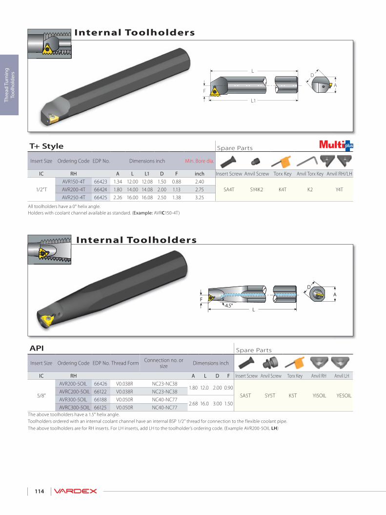
114
D
A
L1
F
L
AD
F
L4.5°
AD
F
L4.5°
Thre
ad T
urni
ng
Tool
hold
ers
Internal Toolholders
Internal Toolholders
API Spare Parts
Insert Size Ordering Code EDP No. Thread Form Connection no. or size Dimensions inch
IC RH A L D F Insert Screw Anvil Screw Torx Key Anvil RH Anvil LH
5/8”
AVR200-5OIL 66426 V0.038R NC23-NC381.80 12.0 2.00 0.90
SA5T SY5T K5T YI5OIL YE5OILAVRC200-5OIL 66122 V0.038R NC23-NC38AVR300-5OIL 66188 V0.050R NC40-NC77
2.68 16.0 3.00 1.50AVRC300-5OIL 66125 V0.050R NC40-NC77
The above toolholders have a 1.5° helix angle.Toolholders ordered with an internal coolant channel have an internal BSP 1/2” thread for connection to the flexible coolant pipe.The above toolholders are for RH inserts. For LH inserts, add LH to the toolholder’s ordering code. (Example AVR200-5OIL LH)
T+ Style Spare Parts
Insert Size Ordering Code EDP No. Dimensions inch Min. Bore dia.
IC RH A L L1 D F inch Insert Screw Anvil Screw Torx Key Anvil Torx Key Anvil RH/LH
1/2”TAVR150-4T 66423 1.34 12.00 12.08 1.50 0.88 2.40
SA4T SY4K2 K4T K2 Y4TAVR200-4T 66424 1.80 14.00 14.08 2.00 1.13 2.75AVR250-4T 66425 2.26 16.00 16.08 2.50 1.38 3.25
All toolholders have a 0° helix angle.Holders with coolant channel available as standard. (Example: AVRC150-4T)
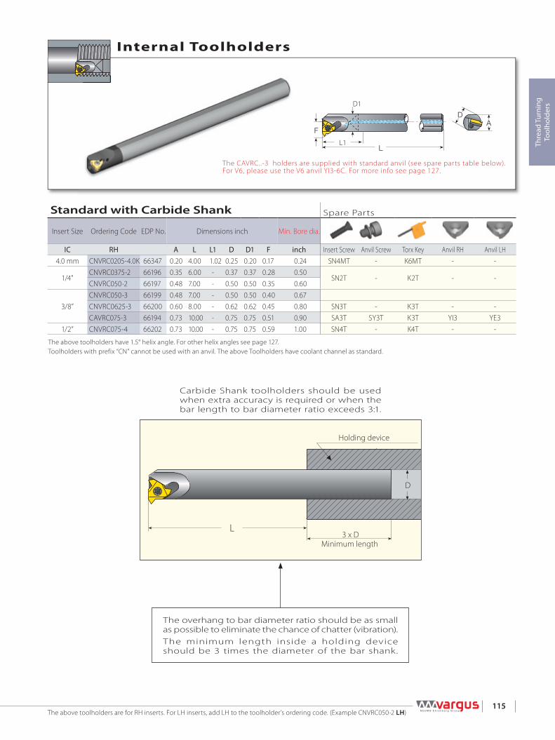
115
L3 x D
Holding device
Minimum length
D
FA
D
L
D1
L1 Thre
ad T
urni
ng
Tool
hold
ers
Internal Toolholders
The CAVRC..-3 holders are supplied with standard anvil (see spare parts table below).For V6, please use the V6 anvil YI3-6C. For more info see page 127.
The above toolholders are for RH inserts. For LH inserts, add LH to the toolholder’s ordering code. (Example CNVRC050-2 LH)
The overhang to bar diameter ratio should be as small as possible to eliminate the chance of chatter (vibration).The minimum length inside a holding device should be 3 times the diameter of the bar shank.
Carbide Shank toolholders should be used when extra accuracy is required or when the bar length to bar diameter ratio exceeds 3:1.
Standard with Carbide Shank Spare Parts
Insert Size Ordering Code EDP No. Dimensions inch Min. Bore dia.
IC RH A L L1 D D1 F inch Insert Screw Anvil Screw Torx Key Anvil RH Anvil LH4.0 mm CNVRC0205-4.0K 66347 0.20 4.00 1.02 0.25 0.20 0.17 0.24 SN4MT - K6MT - -
1/4”CNVRC0375-2 66196 0.35 6.00 - 0.37 0.37 0.28 0.50
SN2T - K2T - -CNVRC050-2 66197 0.48 7.00 - 0.50 0.50 0.35 0.60
3/8”CNVRC050-3 66199 0.48 7.00 - 0.50 0.50 0.40 0.67CNVRC0625-3 66200 0.60 8.00 - 0.62 0.62 0.45 0.80 SN3T - K3T - -CAVRC075-3 66194 0.73 10.00 - 0.75 0.75 0.51 0.90 SA3T SY3T K3T YI3 YE3
1/2” CNVRC075-4 66202 0.73 10.00 - 0.75 0.75 0.59 1.00 SN4T - K4T - -
The above toolholders have 1.5° helix angle. For other helix angles see page 127.Toolholders with prefix “CN” cannot be used with an anvil. The above Toolholders have coolant channel as standard.

116
D
A
L1
D1
LThre
ad T
urni
ng
Tool
hold
ers
Internal Toolholders
The above toolholders have 2.5˚ helix angle.Left Handed Tool Supplied by Request (Example: SNVR 050U-6.0 LH)
DA
L1
D1
L
Internal Toolholders
Mini-3 Adjustable Spare Parts
Insert Size
Ordering Code EDP No. Ordering
Code EDP No. Dimensions inch
IC mm Sleeve Holder A L L1 D D1 Insert Screw Torx Key for Insert Screw Holder Screw x3 Key for Holder Screw6.0 SV0625-8.0 67344 BNVR8.0T-6.0 67326 .584 4 0.315-2.2 .625 .315 SN6MT K6MT S4.0 K2.0
Mini-3 Spare Parts
Insert Size Ordering Code EDP No. Dimensions inch Anti-Vibration System
IC mm RH A L L1 D D1 Insert Screw Torx Key4.0 SNVR 0205-4.0K 42267 0.46 4.00 0.47 0.50 0.20 No SN4MT K6MT
6.0
SNVR 375U-6.0 67338 0.36 3.23 0.63 0.37 0.31 No
SN6MT K6MT
BNVR 375S-6.0 67308 0.36 3.50 0.87 0.37 0.31 Carbide ImplantedBNVR 375M-6.0 67304 0.36 3.86 1.22 0.37 0.31 Carbide ImplantedBNVR 375L-6.0 67301 0.36 4.33 1.69 0.37 0.31 Carbide Implanted
6.0
SNVR 050U-6.0 67341 0.49 3.23 0.63 0.50 0.31 NoBNVR 050S-6.0 67317 0.49 3.50 0.87 0.50 0.31 Carbide ImplantedBNVR 050M-6.0 67313 0.49 3.86 1.22 0.50 0.31 Carbide ImplantedBNVR 050L-6.0 67310 0.49 4.33 1.69 0.50 0.31 Carbide Implanted
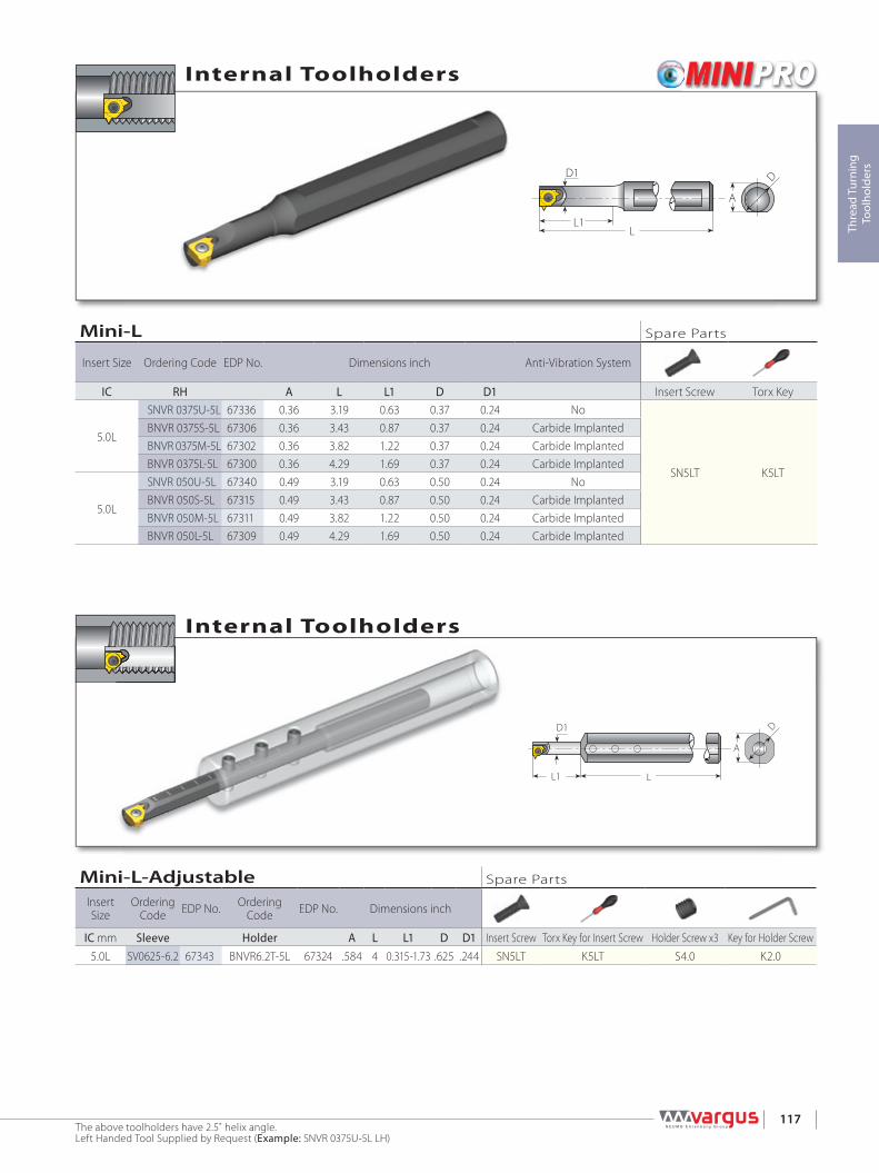
117
D
A
L1
D1
L Thre
ad T
urni
ng
Tool
hold
ers
The above toolholders have 2.5˚ helix angle.Left Handed Tool Supplied by Request (Example: SNVR 0375U-5L LH)
D
A
L1
D1
L
Internal Toolholders
Internal Toolholders
Mini-L Spare Parts
Insert Size Ordering Code EDP No. Dimensions inch Anti-Vibration System
IC RH A L L1 D D1 Insert Screw Torx Key
5.0L
SNVR 0375U-5L 67336 0.36 3.19 0.63 0.37 0.24 No
SN5LT K5LT
BNVR 0375S-5L 67306 0.36 3.43 0.87 0.37 0.24 Carbide ImplantedBNVR 0375M-5L 67302 0.36 3.82 1.22 0.37 0.24 Carbide ImplantedBNVR 0375L-5L 67300 0.36 4.29 1.69 0.37 0.24 Carbide Implanted
5.0L
SNVR 050U-5L 67340 0.49 3.19 0.63 0.50 0.24 NoBNVR 050S-5L 67315 0.49 3.43 0.87 0.50 0.24 Carbide ImplantedBNVR 050M-5L 67311 0.49 3.82 1.22 0.50 0.24 Carbide ImplantedBNVR 050L-5L 67309 0.49 4.29 1.69 0.50 0.24 Carbide Implanted
Mini-L-Adjustable Spare Parts
Insert Size
Ordering Code EDP No. Ordering
Code EDP No. Dimensions inch
IC mm Sleeve Holder A L L1 D D1 Insert Screw Torx Key for Insert Screw Holder Screw x3 Key for Holder Screw5.0L SV0625-6.2 67343 BNVR6.2T-5L 67324 .584 4 0.315-1.73 .625 .244 SN5LT K5LT S4.0 K2.0

118
L
L1D
d
L0
M
Thre
ad T
urni
ng
Tool
hold
ers
Spare Parts
Micro - Double Ended
MicroInsert Dia.
Shank Dia. Ordering Code EDP No. Dimensions inch Location Screw* Clamping Screw x 3
d [mm] D L L1 L0 Screw M Key Screw Key
30.50 SMC050-3.0 41075 3.15
0.35- Short 3.50 4GISM8X28 1.10
K4.0 M4X0.7X4.0 K2.0
0.63- Medium 3.78 4GISM8X21 0.830.63 SMC0625-3.0 40210
3.740.35- Short 4.09 4GISM8X49 1.93
0.75 SMC075-3.0 41080 0.63- Medium 4.37 4GISM8X42 1.65
4
0.50 SMC050-4.0 41092 3.15
0.35- Short 3.50 4GISM8X28 1.10
0.63- Medium 3.78 4GISM8X21 0.83
0.83- Long 3.98 4GISM8X16 0.63
0.63 SMC0625-4.0 402123.74
0.35- Short 4.09 4GISM8X49 1.93
0.63- Medium 4.37 4GISM8X42 1.650.75 SMC075-4.0 41081 0.83- Long 4.57 4GISM8X37 1.46
6
0.50 SMC050-6.0 41517 3.150.35- Short 3.5 4GISM8X28 1.100.63- Medium 3.78 4GISM8X21 0.830.83- Long 3.98 4GISM8X16 0.63
0.63 SMC0625-6.0 402143.74
0.35- Short 4.09 4GISM8X49 1.930.63- Medium 4.37 4GISM8X42 1.65
0.75 SMC075-6.0 41082 0.83- Long 4.57 4GISM8X37 1.46* Every toolholder package contains the full range of location screws needed.
Location Screw
Double Ended
Internal Toolholders
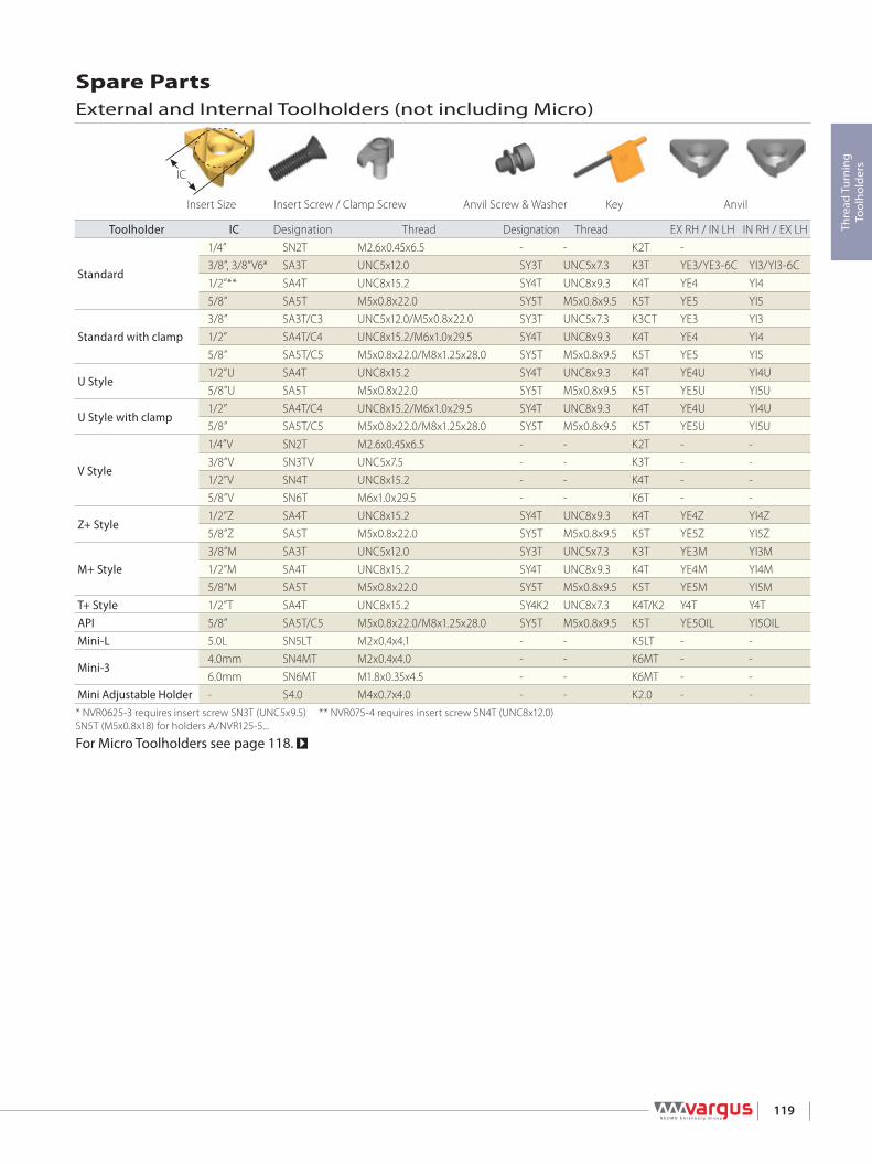
119
Thre
ad T
urni
ng
Tool
hold
ers
Spare PartsExternal and Internal Toolholders (not including Micro)
Toolholder IC Designation Thread Designation Thread EX RH / IN LH IN RH / EX LH
Standard
1/4” SN2T M2.6x0.45x6.5 - - K2T -3/8”, 3/8”V6* SA3T UNC5x12.0 SY3T UNC5x7.3 K3T YE3/YE3-6C YI3/YI3-6C1/2”** SA4T UNC8x15.2 SY4T UNC8x9.3 K4T YE4 YI45/8” SA5T M5x0.8x22.0 SY5T M5x0.8x9.5 K5T YE5 YI5
Standard with clamp3/8” SA3T/C3 UNC5x12.0/M5x0.8x22.0 SY3T UNC5x7.3 K3CT YE3 YI31/2” SA4T/C4 UNC8x15.2/M6x1.0x29.5 SY4T UNC8x9.3 K4T YE4 YI45/8” SA5T/C5 M5x0.8x22.0/M8x1.25x28.0 SY5T M5x0.8x9.5 K5T YE5 YI5
U Style1/2”U SA4T UNC8x15.2 SY4T UNC8x9.3 K4T YE4U YI4U5/8”U SA5T M5x0.8x22.0 SY5T M5x0.8x9.5 K5T YE5U YI5U
U Style with clamp1/2” SA4T/C4 UNC8x15.2/M6x1.0x29.5 SY4T UNC8x9.3 K4T YE4U YI4U5/8” SA5T/C5 M5x0.8x22.0/M8x1.25x28.0 SY5T M5x0.8x9.5 K5T YE5U YI5U
V Style
1/4”V SN2T M2.6x0.45x6.5 - - K2T - -3/8”V SN3TV UNC5x7.5 - - K3T - -1/2”V SN4T UNC8x15.2 - - K4T - -5/8”V SN6T M6x1.0x29.5 - - K6T - -
Z+ Style1/2”Z SA4T UNC8x15.2 SY4T UNC8x9.3 K4T YE4Z YI4Z5/8”Z SA5T M5x0.8x22.0 SY5T M5x0.8x9.5 K5T YE5Z YI5Z
M+ Style3/8”M SA3T UNC5x12.0 SY3T UNC5x7.3 K3T YE3M YI3M1/2”M SA4T UNC8x15.2 SY4T UNC8x9.3 K4T YE4M YI4M5/8”M SA5T M5x0.8x22.0 SY5T M5x0.8x9.5 K5T YE5M YI5M
T+ Style 1/2”T SA4T UNC8x15.2 SY4K2 UNC8x7.3 K4T/K2 Y4T Y4TAPI 5/8” SA5T/C5 M5x0.8x22.0/M8x1.25x28.0 SY5T M5x0.8x9.5 K5T YE5OIL YI5OILMini-L 5.0L SN5LT M2x0.4x4.1 - - K5LT - -
Mini-34.0mm SN4MT M2x0.4x4.0 - - K6MT - -6.0mm SN6MT M1.8x0.35x4.5 - - K6MT - -
Mini Adjustable Holder - S4.0 M4x0.7x4.0 - - K2.0 - -* NVR0625-3 requires insert screw SN3T (UNC5x9.5) ** NVR075-4 requires insert screw SN4T (UNC8x12.0)SN5T (M5x0.8x18) for holders A/NVR125-5...
For Micro Toolholders see page 118.
AnvilKeyAnvil Screw & WasherInsert Screw / Clamp ScrewInsert Size

120
Thre
ad T
urni
ng
Tool
hold
ers
> Technical Data
Thread Turning

122
Thre
ad T
urni
ng
Tech
nica
l Dat
a
Thread Terminology ........................................................................................................................................................................Page 123
Machining a Multi-Start Thread ................................................................................................................................................Page 124
Insert Profile Styles ...........................................................................................................................................................................Page 124
Thread Turning Methods ..............................................................................................................................................................Page 125
Thread Infeed Methods .................................................................................................................................................................Page 125
Calculating the Helix Angle and Choosing the Right Anvil ....................................................................................Page 126
Anvils and Anvil Kits .........................................................................................................................................................................Page 127
Grades and Their Applications ..................................................................................................................................................Page 128
Recommended Grades and Cutting Speeds - (not including Mini and Micro) .........................................Page 129
Recommended Grades and Cutting Speeds - (Mini and Micro) .........................................................................Page 130
Number of Passes .............................................................................................................................................................................Page 131
Cutting Conditions Depends On... .........................................................................................................................................Page 131
Radial infeed per pass.....................................................................................................................................................................Page 132
Number of Passes and Depth of Cut per Pass for Multi+ Inserts ........................................................................Page 138
Step by Step Thread Turning - Examples ............................................................................................................................Page 140
Material Comparison Table .........................................................................................................................................................Page 144
Troubleshooting ................................................................................................................................................................................Page 148
THREAD TURNING TECHNICAL DATA

123
Thre
ad T
urni
ng
Tech
nica
l Dat
a
A thread on the internal surface of a cylinder or cone.
Internal Thread
Left-hand thread
A thread which, when viewed axially, winds in a counterclockwise and receding direction. All left-hand threads are designated LH.
A thread which, when viewed axially, winds in a clockwise and receding direction. Threads are always right-hand unless otherwise specified.
Right-hand thread
LeadThe distance a threaded part moves axially, with respect to a fixed mating part, in one complete revolution. The lead is equal to the pitch multiplied by the number of thread starts.
p x Pitch Diameter
Helix Angle Lead
A thread which, when viewed axially, winds in a counterclockwise and receding direction. All left-hand threads are designated LH.
A thread which, when viewed axially, winds in a clockwise and receding direction. Threads are always right-hand unless otherwise specified.
External Thread A thread on the external surface of a cylinder screw or cone
Pitch
Root
Crest
ThreadAngleHelixAngle
External Thread Major DiameterThe largest diameter of a screw thread.
Pitch DiameterOn a straight thread, the diameter of an imaginary cylinder, the surface of which cuts the thread forms where the width of the thread and groove are equal.
Minor DiameterThe smallest diameter of a screw thread.
Helix AngleFor a straight thread, where the lead of the thread and the pitch diameter circle circumference form a right angled triangle, the helix angle is the angle opposite the lead.
Straight ThreadA thread formed on a cylinder
Taper ThreadA thread formed on a cone
Depth of ThreadThe distance between crest and root measured normal to the axis.
PitchThe distance between corresponding points on adjacent thread forms measured parallel to the axis. This distance can be defined in millimeters or by the tpi (threads per inch), which is the reciprocal of the pitch.
Major ØPitch ØMinor Ø
Nominal DiameterThe diameter from which the diameter limits are derived by the application of deviation allowances and tolerances.
Left-hand thread Right-hand thread
Thread Terminology
The Helix Angle b

124
Thre
ad T
urni
ng
Tech
nica
l Dat
a
The V partial profile insert cuts without topping the outer diameter of the thread. The same insert can be used for a range of different thread pitches which have a common thread angle.
First Start Machined Second Start Machined Third Start Machined (Final, 3 Starts Thread)
Lead = 3 x Pitch
PitchPitch
PitchLead Lead
Full Profile
Semi Full
Partial Profile
Full Profile for Fine Pitches
The full profile for Fine Pitches will form a complete thread.The topping of the outer diameter is generated by the second tooth.
The full profile insert will form a complete thread profile including the crest. For every thread pitch and standard, a separate insert is required.
The Semi profile insert will form a complete thread including crest radius but without topping the outer diameter.Mainly used for trapezoidal profiles.
Machining a Multi-Start Thread
Insert Profile Styles
A thread in which the lead is an integral multiple, greater than one, of the pitch. A multi-start thread permits a more rapid advance without a coarser (larger) thread form.

125
Thre
ad T
urni
ng
Tech
nica
l Dat
a
21
43
65
87
Thread Turning Methods
1-3°
Thread Inserts & Toolholder Rotation Feed Direction Helix Method Drawing No.
Right Hand ExternalEX RH Counterclockwise Towards chuck Regular 1EX LH Clockwise From chuck Reversed 2
Right Hand InternalIN RH Counterclockwise Towards chuck Regular 3IN LH Clockwise From chuck Reversed 4
Left Hand ExternalEX LH Clockwise Towards chuck Regular 5EX RH Counterclockwise From chuck Reversed 6
Left Hand InternalIN LH Clockwise Towards chuck Regular 7IN RH Counterclockwise From chuck Reversed 8
External RH Thread External LH Thread
Internal RH Thread
Radial Infeed
Radial infeed is the simplest and quickest method. The feed is perpendicular to the turning axis, and both flanks of the insert perform the cutting operation. Radial infeed is recommended in 3 cases: When the pitch is smaller than 16 tpi For material with short chips For work with hardened material
Flank infeed is recommended in the following cases: When the thread pitch is greater than 16 tpi., using the radial method, the effective cutting edge length is too large, resulting in chatter. For TRAPEZ and ACME. The radial method result in three cutting edges, making chip flow very difficult.
Use of the alternate flank method is recommended especially in large pitches and for materials with long chips.This method divides the load equally on both flanks, resulting in equal wear along the cutting edges. Alternate flank infeed requires more complicated programming, and is not available on all lathes.
Flank Infeed (modified) Alternate Flank Infeed
Internal LH Thread
Thread Infeed Methods

126
Thre
ad T
urni
ng
Tech
nica
l Dat
a
α = arctan (tan Ø/2 x tanδ)
α
δφ
A
A
A - A
10°1°14'7°10'2°36'5°48'5°48'
60°, UN,ISO
ACME BUTTRESS INSERT
2°36'
βp
D
The helix angle is calculated by the following formula:
β - Helix angle [ ° ]P - Pitch [inch]N - No. of startsD - Pitch diameter [inch]Lead = P x N
Flank Clearance Angle a (For External Inserts)
Calculating the Helix Angle b
The helix angle can also be found from the diagram below.
β= arctan PxNπxD
Calculating the Helix Angle and ChoosingThe Right Anvil
Vardex toolholders are designed to tilt the insert when seated in the toolholder (10° for external, 15° for internal tooling). This results in the differing flank clearance angles, based on the
geometry of the insert. To ensure that the side of the insert cutting edge will not rub on the workpiece, it is most important that the insert helix angle be correct - especially in profiles with small enclosed flank angles. This correction is provided by Vardex anvils.
Where: a - Flank clearance angle d - Tilt angle Ø - Enclosed flank angle
5° 4° 3° =1°β=2°β
1
2
3
4
5
6
7
8
9
11
10
12
1
2
3
4
5
6
7
8
9
11
10
12
2” 4”
2.5
3
3.5
44.5567911141824
2.5
3
3.544.55
67911141824
=-1 °
=0°
β
β
β = -2 °
2.25
2.25
6” 8”0
1.5 °H1
−β
1.5 °
β
H1
Helix Angle Diagram
The dimension H1 (cutting edge height)remains constant with every insert/ anvilcombination.
AnvilangleStandard toolholder
pocket angle
Reversedhelix angle
Feed towardsthe tailstock
Anvilangle
Standardhelix angle
Feed towardsthe chuck
Standard toolholderpocket angle
Fee
d d
ire
ctio
n t
ow
ard
s th
e c
hu
ck
RH T
hrea
d/ R
H To
olin
g
Fee
d d
ire
ctio
n t
ow
ard
s th
e t
ails
tock
LH T
hrea
d/ L
H To
olin
gLH
Thr
ead/
RH
Tool
ing
RH T
hrea
d/ L
H To
olin
g
SpecialToolholders
Special Toolholders
*For Multi-start threads,use the lead value instead of the pitch
Pitch P*[mm]
Pitch P*[tpi]
Pitch diameter [inch]
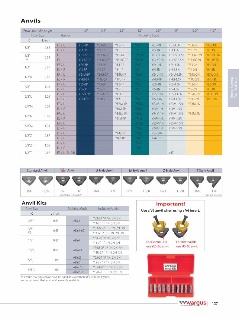
127
Thre
ad T
urni
ng
Tech
nica
l Dat
a
Important!Use a V6 anvil when using a V6 insert.
Anvils
Resultant Helix Angle 4.5° 3.5° 2.5° 1.5° 0.5° 0° -0.5° -1.5°Insert Size Holder Ordering Code
IC L inch
3/8” 0.63ER / IL YE3-3P YE3-2P YE3-1P YE3 YE3-1N YE3-1.5N YE3-2N YE3-3NEL / IR YI3-3P YI3-2P YI3-1P YI3 YI3-1N YI3-1.5N YI3-2N YI3-3N
3/8” V6 0.63
ER YE3-6C-3P YE3-6C-2P YE3-6C-1P YE3-6C YE3-6C-1N YE3-6C-1.5N YE3-6C-2N YE3-6C-3NIR YI3-6C-3P YI3-6C-2P YI3-6C-1P YI3-6C YI3-6C-1N YI3-6C-1.5N YI3-6C-2N YI3-6C-3N
1/2” 0.87ER / IL YE4-3P YE4-2P YE4-1P YE4 YE4-1N YE4-1.5N YE4-2N YE4-3NEL / IR YI4-3P YI4-2P YI4-1P YI4 YI4-1N YI4-1.5N YI4-2N YI4-3N
1/2”U 0.87ER / IL YE4U-3P YE4U-2P YE4U-1P YE4U YE4U-1N YE4U-1.5N YE4U-2N YE4U-3NEL / IR YI4U-3P YI4U-2P YI4U-1P YI4U YI4U-1N YI4U-1.5N YI4U-2N YI4U-3N
5/8” 1.06ER / IL YE5-3P YE5-2P YE5-1P YE5 YE5-1N YE5-1.5N YE5-2N YE5-3NEL / IR YI5-3P YI5-2P YI5-1P YI5 YI5-1N YI5-1.5N YI5-2N YI5-3N
5/8”U 1.06ER / IL YE5U-3P YE5U-2P YE5U-1P YE5U YE5U-1N YE5U-1.5N YE5U-2N YE5U-3NEL / IR YI5U-3P YI5U-2P YI5U-1P YI5U YI5U-1N YI5U-1.5N YI5U-2N YI5U-3N
3/8”M 0.63ER / IL YE3M-1P YE3M YE3M-1N YE3M-1.5N YE3M-2NEL / IR YI3M-1P YI3M YI3M-1N YI3M-1.5N
1/2”M 0.87ER / IL YE4M-1P YE4M YE4M-1N YE4M-1.5N YE4M-2NEL / IR YI4M-1P YI4M YI4M-1N YI4M-1.5N
5/8”M 1.06ER / IL YE5M YE5M-1N YE5M-1.5NEL / IR YI5M YI5M-1N YI5M-1.5N
1/2”Z 0.87ER / IL YE4Z-1P YE4Z YE4Z-1NEL / IR YI4Z-1P YI4Z YI4Z-1N
5/8”Z 1.06ER / IL YE5ZEL / IR YI5Z
1/2”T 0.87 ER / IL EL / IR Y4T
Standard Anvil Anvil U Style Anvil M Style Anvil Z Style Anvil T Style Anvil
ER/IL EL/IR ER IR ER/IL EL/IR ER/IL EL/IR ER/IL EL/IR ER/IL EL/IR V6 is indicated on the backside Same anvil turned over
Anvil KitsAnvil Size Ordering Code Included Anvils:
IC L inch
3/8” 0.63 ABY3YE3-2P, 1P, 1N, 2N, 3NYI3-2P, 1P, 1N, 2N, 3N
3/8” V6 0.63 ABY3-6C
YE3-6C-2P, 1P, 1N, 2N, 3NYI3-6C-2P, 1P, 1N, 2N, 3N
1/2” 0.87 ABY4YE4-2P, 1P, 1N, 2N, 3NYI4-2P, 1P, 1N, 2N, 3N
1/2”U 0.87 ABY4UYE4U-2P, 1P, 1N, 2N, 3NYI4U-2P, 1P, 1N, 2N, 3N
5/8” 1.06ABYE5 YE5-2P, 1P, 1N, 2N, 3NABYI5 YI5-2P, 1P, 1N, 2N, 3N
5/8”U 1.06ABYE5U YE5U-2P, 1P, 1N, 2N, 3NABYI5U YI5U-2P, 1P, 1N, 2N, 3N
To ensure that you always have on hand an assortment of anvils for any job, we recommend that anvil kits be readily available.
For External RHuse YE3-6C anvil.
For Internal RHuse Yl3-6C anvil.

128
Thre
ad T
urni
ng
Tech
nica
l Dat
a
Grades and Their ApplicationsGeneral Use
VKX VTX VCB
Superior general purpose grade, excellent in steels and stainless steels, recommended for rigid cutting conditions, ground or sintered chipbreaker styles. TiN coated.
General purpose grade with tough submicron substrate. Provides good fracture toughness in non-rigid cutting conditions. TiAlN coated.
Vardex sintered chipbreaker with ground profile for machining materials with long chips. TiAlN coated.
Stainless Steel Non Ferrous, High Temperature Alloys and Titanium
VM7 VK2 VK2P
Specialty grade for threading stainless steel. Multi-layer PVD coated.
Uncoated grade for non-ferrous, aluminium, high temperature and titanium alloys.
Highly-polished version of the VK2 uncoated grade for high quality surface finish in aluminium.
Micro Mini “5L”& Mini IC 6.0 Mini IC 4.0
VMX VHX VTX
General purpose carbide grade for Micro double-ended inserts. TiN coated.
HSS grade for Mini "L" and Mini 6.0 inserts; for low cutting speeds, TiN coated.
Carbide grade for Mini 4.0. For machining stainless steel and general use. TiAlN coated.
VKP VBX
General purpose carbide grade for Mini "L" and Mini 6.0 inserts, TiN coated.
Carbide grade for Mini 4.0. For machining steel and general use. TiCN coated.

129
Thre
ad T
urni
ng
Tech
nica
l Dat
a
Calculation of N [RPM]
Recommended Grades and Cutting Speeds Vc [ft/min]not Including MiniPro Line
Material Group
Vard
ex N
o.Material
Hardness Brinell
HB
Vc [ft/min]
Coated Uncoated
VKX VCB VM7 VTX VK2 / VK2P
PSteel
1Unalloyed steel
Low carbon (C=0.1-0.25%) 125 377-623 377-623 377-6232 Medium carbon (C=0.25-0.55%) 150 328-574 328-541 328-5743 High carbon (C=0.55-0.85%) 170 295-541 295-508 295-5414
Low alloy steel(alloying elements≤5%)
Non hardened 180 328-590 328-590 328-5905 Hardened 275 246-459 246-459 246-4596 Hardened 350 229-443 229-443 229-4437 High alloy steel
(alloying elements>5%) Annealed 200 262-393 262-393 262-393
8 Hardened 325 164-328 164-328 164-3289
Cast steel Low alloy (alloying elements <5%) 200 229-426 229-426 229-426
10 High alloy (alloying elements >5%) 225 197-393 197-393 197-393
MStainless
Steel
11 Stainless steel Feritic
Non hardened 200 229-426 229-426 229-492 229-42612 Hardened 330 197-377 164-311 197-410 197-37713 Stainless steel
Austenitic Austenitic 180 295-459 262-393 295-524 295-459
14 Super Austenitic 200 131-361 98-328 131-393 131-36115 Stainless steel
Cast feritic Non hardened 200 295-393 295-393 295-492 295-393
16 Hardened 330 213-361 213-361 213-393 213-36117 Stainless steel
Cast austenitic Austenitic 200 279-361 279-361 279-393 279-361
18 Hardened 330 197-328 197-328 197-361 197-328
KCast Iron
28 Malleable Cast iron
Ferritic (short chips) 130 197-229 229-393 197-22929 Pearlitic (long chips) 230 197-475 229-393 197-47530
Grey Cast iron Low tensile strength 180 229-426 229-426 229-426
31 High tensile strength 260 197-377 197-328 197-37732
Nodular SG iron Feritic 160 410-524 410-524 410-524
33 Pearlitic 260 295-393 295-393 295-393
N(K)Non-Ferrous
Metals
34 Aluminium alloys Wrought
Non aging 60 328-1196 328-819 328-1196 328-81935 Aged 100 262-721 262-590 262-721 262-52436
Aluminium alloys Cast 75 656-1312 656-1312 656-1312 262-393
37 Cast & aged 90 656-918 656-918 656-918 229-32838 Aluminium alloys Cast Si 13-22% 130 197-590 197-492 197-590 164-39339 Copper and
copper alloys Brass 90 262-738 262-688 262-738 229-557
40 Bronze and non leaded copper 100 262-836 262-688 262-836 229-557
S(M)Heat Resistant
Material
19
High temperaturealloys
Annealed (Iron based) 200 148-197 148-197 148-197 98-16420 Aged (Iron based) 280 98-164 98-164 98164 82-13121 Annealed (Nickel or Cobalt based) 250 66-98 66-98 66-98 66-9822 Aged (Nickel or Cobalt based) 350 49-82 49-82 49-82 49-8223
Titanium alloys Pure 99.5 Ti 400Rm 459-557 459-557 459-557 197-328
24 a+b alloys 1050Rm 164-229 164-229 164-229 131-197
H(K)Hardened Material
25Extra hard steel Hardened & tempered
45-50HRc 148-197 148-197 148-197
26 51-55HRc 131-164 131-164 131-164
N - Revolution Per Minute [RPM]Vc - Cutting Speed [ft/min]D - Workpiece Diameter [inch]
DN
Vc
12 x V c
N x π x D12
N = π x D
Vc =

130
Thre
ad T
urni
ng
Tech
nica
l Dat
a
Recommended Grades and Cutting SpeedsVc [ft/min] Mini, Micro
MaterialGroup Va
rdex
No.
Material
Hardness Brinell
HB
Vc [ft/min]
Coated
VMX (Micro)
VKP(Mini)
VTX (Mini)
VHX (Mini)
PSteel
1Unalloyed steel
Low carbon (C=0.1-0.25%) 125 164-393 459-656 492-656 66-1642 Medium carbon (C=0.25-0.55%) 150 131-328 393-590 426-590 49-1313 High Carbon (C=0.55-0.85%) 170 98-262 361-590 393-590 49-984
Low alloy steel(alloying elements≤5%)
Non hardened 180 164-229 328-508 361-508 66-1485 Hardened 275 131-197 295-475 328-475 33-826 Hardened 350 98-164 262-443 295-443 33-827 High alloy steel
(alloying elements>5%) Annealed 200 98-164 213-377 229-377
8 Hardened 325 82-131 164-328 197-3289
Cast steel Low alloy (alloying elements <5%) 200 98-164 98-164 98-164 82-131
10 High alloy (alloying elements >5%) 225 82-131 82-131 98-131 82- 131
MStainless
Steel
11 Stainless steel Feritic
Non hardened 200 197-328 262-393 295-39312 Hardened 330 131-197 180-311 197-31113 Stainless steel
Austenitic Austenitic 180 164-295 197-328 229-328
14 Super Austenitic 200 131-197 164-295 197-29515 Stainless steel
Cast Feritic Non hardened 200 131-197 197-262 229-262
16 Hardened 330 98-164 148-213 164-21317 Stainless steel
Cast austenitic Austenitic 200 131-197 164-229 197-229
18 Hardened 330 98-164 131-197 131-197
KCast Iron
28 Malleable Cast iron
Ferritic (short chips) 130 164-229 197-262 229-26229 Pearlitic (long chips) 230 164-229 197-262 229-26230
Grey cast iron Low tensile strength 180 164-229 197-262 229-262
31 High tensile strength 260 131-197 131-229 131-22932
Nodular SG iron Feritic 160 164-229 197-262 229-262
33 Pearlitic 260 197-262 229-295 262-295
N(K)Non-Ferrous
Metals
34 Aluminium alloys Wrought
Non aging 60 328-983 262-787 295-787 98-19735 Aged 100 328-492 328-557 361-557 82-16436
Aluminium alloys Cast 75 328-492 328-492 361-492 82-164
37 Cast & aged 90 197-328 197-328 229-328 66-13138 Aluminium alloys Cast Si 13-22% 130 328-492 328-492 361-492 49-9839 Copper and
copper alloys Brass 90 197-328 262-656 295-656 49-115
40 Bronze and non leaded copper 100 197-328 262-656 295-656 49-115
S(M)Heat Resistant
Material
19
High temperaturealloys
Annealed (Iron based ) 200 82-148 82-148 98-14820 Aged (Iron based) 280 66-98 66-98 66-9821 Annealed (Nickel or Cobalt based) 250 49-66 49-66 49-6622 Aged (Nickel or Cobalt based) 350 33-49 33-49 49-6623
Titanium alloys Pure 99.5 Ti 400Rm 197-328 197-328 229-328
24 α+β alloys 1050Rm 131-164 131-164 131-164
H(K)Hardened Material
25Extra hard steel Hardened & tempered
45-50HRc 66-131 66-131 66-131
26 51-55HRc 66-131 66-131 66-131
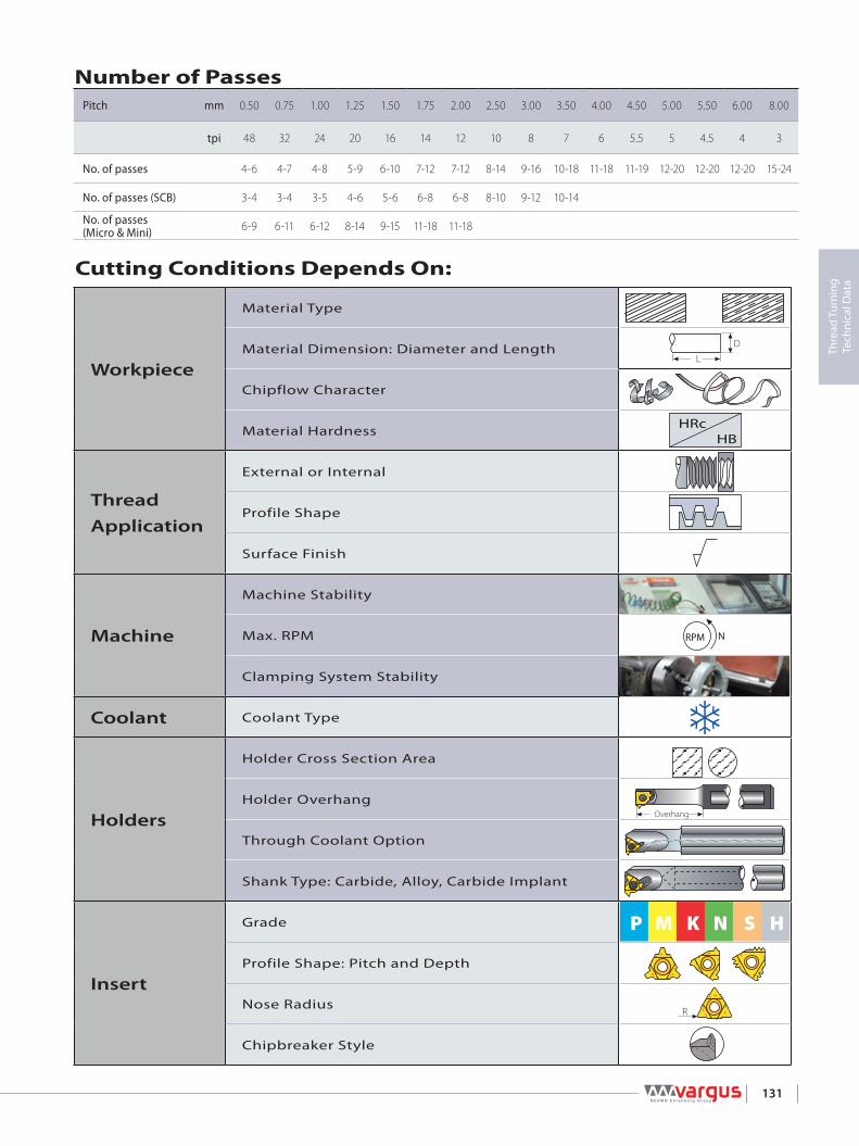
131
Thre
ad T
urni
ng
Tech
nica
l Dat
a
Overhang
P M K N S H
R
D
L
HRcHB
RPM N
Number of PassesPitch mm 0.50 0.75 1.00 1.25 1.50 1.75 2.00 2.50 3.00 3.50 4.00 4.50 5.00 5.50 6.00 8.00
tpi 48 32 24 20 16 14 12 10 8 7 6 5.5 5 4.5 4 3
No. of passes 4-6 4-7 4-8 5-9 6-10 7-12 7-12 8-14 9-16 10-18 11-18 11-19 12-20 12-20 12-20 15-24
No. of passes (SCB) 3-4 3-4 3-5 4-6 5-6 6-8 6-8 8-10 9-12 10-14
No. of passes(Micro & Mini) 6-9 6-11 6-12 8-14 9-15 11-18 11-18
Cutting Conditions Depends On:
Workpiece
Material Type
Material Dimension: Diameter and Length
Chipflow Character
Material Hardness
ThreadApplication
External or Internal
Profile Shape
Surface Finish
Machine
Machine Stability
Max. RPM
Clamping System Stability
Coolant Coolant Type
Holders
Holder Cross Section Area
Holder Overhang
Through Coolant Option
Shank Type: Carbide, Alloy, Carbide Implant
Insert
Grade
Profile Shape: Pitch and Depth
Nose Radius
Chipbreaker Style

132
Thre
ad T
urni
ng
Tech
nica
l Dat
a
Radial infeed per passUN ExternalNumber of passes
Pitch/tpi
Lower Cutting Speed Higher32 28 24 20 18 16 14 13 12 11 10 9 8 7 6 5 4.5 4
1 0.007 0.007 0.007 0.008 0.009 0.009 0.009 0.009 0.010 0.011 0.011 0.011 0.012 0.014 0.014 0.017 0.017 0.0182 0.006 0.006 0.006 0.007 0.008 0.008 0.008 0.009 0.010 0.009 0.010 0.010 0.011 0.013 0.013 0.015 0.016 0.0173 0.004 0.004 0.006 0.005 0.006 0.006 0.006 0.007 0.007 0.007 0.007 0.008 0.008 0.010 0.010 0.012 0.014 0.0144 0.002 0.004 0.004 0.004 0.005 0.005 0.005 0.006 0.006 0.006 0.006 0.007 0.007 0.008 0.009 0.011 0.011 0.0135 0.002 0.002 0.004 0.004 0.004 0.004 0.005 0.006 0.006 0.006 0.006 0.006 0.007 0.008 0.009 0.009 0.0126 0.002 0.002 0.004 0.004 0.005 0.005 0.005 0.005 0.006 0.006 0.007 0.007 0.009 0.009 0.0107 0.002 0.004 0.004 0.005 0.005 0.005 0.005 0.006 0.006 0.007 0.008 0.008 0.0098 0.002 0.002 0.002 0.004 0.005 0.005 0.005 0.006 0.006 0.007 0.008 0.0099 0.002 0.004 0.005 0.005 0.006 0.006 0.007 0.007 0.00910 0.002 0.004 0.005 0.005 0.005 0.007 0.007 0.00811 0.005 0.007 0.006 0.00712 0.004 0.006 0.006 0.00713 0.002 0.005 0.006 0.00614 0.002 0.006 0.00615 0.005 0.00516 0.002 0.002
UN InternalNumber of passes
Pitch/tpi
Lower Cutting Speed Higher32 28 24 20 18 16 14 13 12 11 10 9 8 7 6 5 4.5 4
1 0.007 0.006 0.007 0.007 0.009 0.009 0.009 0.009 0.010 0.010 0.011 0.011 0.012 0.013 0.014 0.017 0.017 0.0182 0.005 0.005 0.006 0.006 0.007 0.007 0.008 0.008 0.009 0.009 0.010 0.010 0.011 0.013 0.013 0.015 0.015 0.0173 0.004 0.004 0.005 0.005 0.005 0.006 0.006 0.006 0.007 0.007 0.007 0.007 0.008 0.009 0.010 0.012 0.013 0.0154 0.002 0.003 0.004 0.004 0.005 0.005 0.005 0.005 0.006 0.006 0.006 0.006 0.007 0.008 0.008 0.010 0.010 0.0125 0.002 0.002 0.004 0.004 0.004 0.004 0.005 0.005 0.006 0.005 0.006 0.006 0.007 0.007 0.009 0.009 0.0116 0.002 0.002 0.004 0.004 0.004 0.004 0.005 0.005 0.005 0.005 0.006 0.006 0.008 0.008 0.0097 0.002 0.004 0.004 0.004 0.005 0.004 0.005 0.005 0.006 0.006 0.007 0.007 0.0098 0.002 0.002 0.002 0.004 0.004 0.004 0.004 0.005 0.006 0.007 0.007 0.0089 0.004 0.004 0.004 0.004 0.005 0.005 0.006 0.007 0.008
10 0.002 0.002 0.004 0.004 0.005 0.005 0.006 0.006 0.00711 0.002 0.004 0.004 0.005 0.006 0.006 0.00712 0.002 0.002 0.004 0.006 0.006 0.00613 0.004 0.005 0.006 0.00614 0.002 0.002 0.005 0.00615 0.005 0.00516 0.002 0.002

133
Thre
ad T
urni
ng
Tech
nica
l Dat
a
Radial infeed per passISO ExternalNumber of passes
Lower Cutting Speed HigherPitch/mm 0.5 0.75 1 1.25 1.5 1.75 2 2.5 3 3.5 4 4.5 5 5.5 6
1 0.004 0.006 0.007 0.007 0.009 0.009 0.009 0.010 0.011 0.013 0.013 0.015 0.016 0.017 0.0182 0.003 0.006 0.006 0.007 0.008 0.008 0.009 0.009 0.010 0.012 0.012 0.013 0.015 0.016 0.0173 0.003 0.004 0.005 0.006 0.007 0.006 0.007 0.007 0.008 0.009 0.009 0.011 0.013 0.013 0.0144 0.002 0.002 0.004 0.004 0.006 0.005 0.006 0.007 0.007 0.008 0.009 0.009 0.011 0.011 0.0125 0.002 0.004 0.005 0.004 0.006 0.006 0.006 0.007 0.007 0.009 0.009 0.009 0.0116 0.002 0.002 0.004 0.005 0.005 0.006 0.007 0.007 0.008 0.009 0.009 0.0097 0.004 0.004 0.005 0.005 0.006 0.006 0.007 0.008 0.008 0.0098 0.002 0.002 0.004 0.005 0.006 0.006 0.007 0.007 0.007 0.0089 0.004 0.005 0.006 0.006 0.006 0.007 0.007 0.008
10 0.002 0.004 0.005 0.005 0.006 0.007 0.007 0.00711 0.004 0.004 0.005 0.006 0.006 0.006 0.00712 0.002 0.002 0.005 0.005 0.006 0.006 0.00613 0.004 0.005 0.005 0.005 0.00614 0.002 0.002 0.002 0.005 0.00615 0.005 0.00516 0.002 0.002
ISO InternalNumber of passes
Lower Cutting Speed HigherPitch/mm 0.5 0.75 1 1.25 1.5 1.75 2 2.5 3 3.5 4 4.5 5 5.5 6
1 0.004 0.006 0.007 0.007 0.009 0.009 0.010 0.011 0.011 0.013 0.013 0.014 0.017 0.017 0.0182 0.003 0.005 0.006 0.006 0.008 0.008 0.009 0.010 0.010 0.012 0.012 0.013 0.015 0.015 0.0173 0.003 0.004 0.004 0.005 0.006 0.006 0.007 0.007 0.008 0.009 0.009 0.011 0.012 0.013 0.0144 0.002 0.002 0.004 0.004 0.005 0.005 0.006 0.006 0.006 0.007 0.008 0.009 0.010 0.010 0.0115 0.002 0.004 0.004 0.004 0.004 0.005 0.006 0.007 0.007 0.008 0.009 0.009 0.0006 0.002 0.002 0.003 0.004 0.005 0.005 0.006 0.006 0.007 0.008 0.008 0.0097 0.003 0.004 0.004 0.005 0.006 0.006 0.006 0.007 0.007 0.0088 0.002 0.002 0.004 0.004 0.005 0.005 0.006 0.006 0.007 0.0079 0.004 0.004 0.005 0.005 0.006 0.006 0.006 0.007
10 0.002 0.004 0.004 0.005 0.005 0.006 0.006 0.00611 0.003 0.004 0.004 0.005 0.006 0.006 0.00612 0.002 0.002 0.004 0.005 0.006 0.006 0.00613 0.004 0.004 0.005 0.005 0.00614 0.002 0.002 0.002 0.005 0.00515 0.005 0.005

134
Thre
ad T
urni
ng
Tech
nica
l Dat
a
Radial infeed per passUNJ External & InternalNumber of passes
Lower Cutting Speed HigherPitch/tpi 32 28 24 20 18 16 14 12 10 8
1 0.006 0.006 0.007 0.007 0.008 0.009 0.009 0.010 0.010 0.0112 0.006 0.005 0.006 0.006 0.007 0.007 0.008 0.009 0.009 0.0113 0.004 0.004 0.006 0.005 0.006 0.006 0.006 0.007 0.007 0.0084 0.002 0.004 0.004 0.004 0.005 0.005 0.005 0.006 0.006 0.0065 0.002 0.002 0.004 0.004 0.004 0.004 0.005 0.005 0.0066 0.002 0.002 0.004 0.004 0.004 0.005 0.0057 0.002 0.004 0.004 0.005 0.0058 0.002 0.002 0.004 0.0059 0.004 0.005
10 0.002 0.00411 0.00412 0.002
NPT External & InternalNumber of passes
Lower Cutting Speed HigherPitch/tpi 27 18 14 11.5 8
1 0.008 0.008 0.009 0.009 0.0102 0.006 0.006 0.007 0.007 0.0093 0.006 0.006 0.006 0.007 0.0084 0.005 0.005 0.006 0.006 0.0075 0.005 0.005 0.005 0.006 0.0076 0.004 0.004 0.005 0.005 0.0077 0.004 0.004 0.004 0.005 0.0078 0.002 0.002 0.004 0.005 0.0079 0.004 0.004 0.006
10 0.002 0.004 0.00611 0.004 0.00612 0.002 0.00513 0.00514 0.00415 0.002
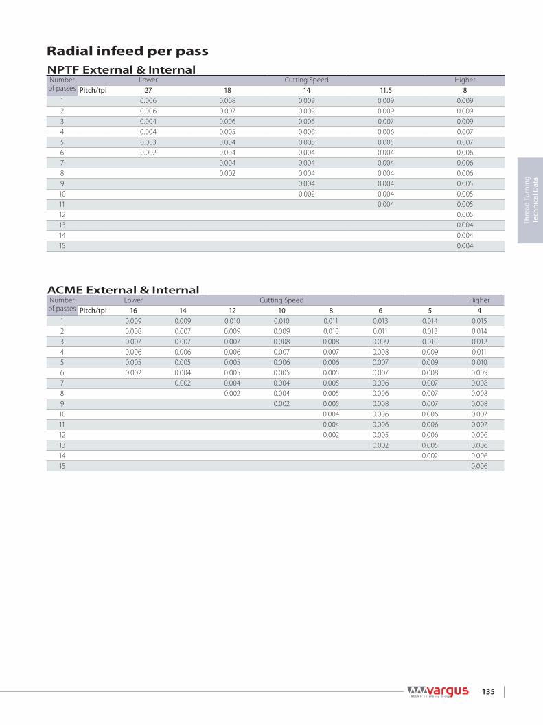
135
Thre
ad T
urni
ng
Tech
nica
l Dat
a
Radial infeed per passNPTF External & InternalNumber of passes
Lower Cutting Speed HigherPitch/tpi 27 18 14 11.5 8
1 0.006 0.008 0.009 0.009 0.0092 0.006 0.007 0.009 0.009 0.0093 0.004 0.006 0.006 0.007 0.0094 0.004 0.005 0.006 0.006 0.0075 0.003 0.004 0.005 0.005 0.0076 0.002 0.004 0.004 0.004 0.0067 0.004 0.004 0.004 0.0068 0.002 0.004 0.004 0.0069 0.004 0.004 0.005
10 0.002 0.004 0.00511 0.004 0.00512 0.00513 0.00414 0.00415 0.004
ACME External & InternalNumber of passes
Lower Cutting Speed HigherPitch/tpi 16 14 12 10 8 6 5 4
1 0.009 0.009 0.010 0.010 0.011 0.013 0.014 0.0152 0.008 0.007 0.009 0.009 0.010 0.011 0.013 0.0143 0.007 0.007 0.007 0.008 0.008 0.009 0.010 0.0124 0.006 0.006 0.006 0.007 0.007 0.008 0.009 0.0115 0.005 0.005 0.005 0.006 0.006 0.007 0.009 0.0106 0.002 0.004 0.005 0.005 0.005 0.007 0.008 0.0097 0.002 0.004 0.004 0.005 0.006 0.007 0.0088 0.002 0.004 0.005 0.006 0.007 0.0089 0.002 0.005 0.008 0.007 0.008
10 0.004 0.006 0.006 0.00711 0.004 0.006 0.006 0.00712 0.002 0.005 0.006 0.00613 0.002 0.005 0.00614 0.002 0.00615 0.006

136
Thre
ad T
urni
ng
Tech
nica
l Dat
a
Radial infeed per passSTUB ACME External & InternalNumber of passes
Lower Cutting Speed HigherPitch/tpi 16 14 12 10 8 6 5 4
1 0.007 0.009 0.009 0.009 0.010 0.012 0.013 0.0142 0.005 0.006 0.006 0.007 0.007 0.009 0.010 0.0113 0.004 0.005 0.005 0.006 0.007 0.007 0.008 0.0094 0.002 0.004 0.004 0.006 0.006 0.007 0.007 0.0085 0.002 0.004 0.005 0.006 0.006 0.007 0.0086 0.002 0.004 0.005 0.006 0.006 0.0077 0.002 0.004 0.006 0.006 0.0068 0.002 0.005 0.006 0.0069 0.002 0.005 0.005
10 0.002 0.00511 0.00412 0.002
W External & InternalNumber of passes
Lower Cutting Speed HigherPitch/tpi 28 26 20 19 18 16 14 12 11 10 9 8 7 6 5 4.5 4
1 0.007 0.007 0.008 0.008 0.008 0.008 0.009 0.010 0.010 0.011 0.011 0.012 0.013 0.014 0.017 0.017 0.0182 0.006 0.006 0.007 0.007 0.007 0.007 0.008 0.010 0.009 0.010 0.010 0.011 0.013 0.013 0.016 0.016 0.0173 0.004 0.005 0.006 0.006 0.006 0.006 0.007 0.008 0.008 0.008 0.008 0.009 0.010 0.011 0.014 0.014 0.0144 0.004 0.004 0.005 0.005 0.005 0.005 0.006 0.006 0.007 0.007 0.007 0.007 0.009 0.009 0.011 0.012 0.0135 0.002 0.002 0.004 0.005 0.005 0.004 0.005 0.006 0.006 0.006 0.006 0.007 0.008 0.008 0.010 0.010 0.0126 0.002 0.002 0.002 0.004 0.005 0.006 0.006 0.006 0.006 0.006 0.007 0.008 0.009 0.009 0.0117 0.004 0.043 0.005 0.005 0.005 0.006 0.006 0.007 0.007 0.009 0.009 0.0118 0.002 0.002 0.002 0.005 0.005 0.005 0.006 0.006 0.007 0.008 0.009 0.0109 0.002 0.005 0.005 0.005 0.006 0.006 0.007 0.008 0.009
10 0.002 0.005 0.005 0.006 0.006 0.007 0.007 0.00911 0.002 0.005 0.005 0.006 0.007 0.007 0.00812 0.002 0.002 0.005 0.006 0.006 0.00713 0.005 0.005 0.006 0.00714 0.002 0.002 0.006 0.00615 0.005 0.005

137
Thre
ad T
urni
ng
Tech
nica
l Dat
a
Radial infeed per passBSPT External & InternalNumber of passes
Lower Cutting Speed HigherPitch/tpi 28 19 14 11
1 0.007 0.009 0.009 0.0102 0.006 0.007 0.008 0.0093 0.004 0.006 0.007 0.0084 0.004 0.005 0.006 0.0075 0.002 0.005 0.005 0.0066 0.002 0.005 0.0067 0.004 0.0058 0.002 0.0059 0.002
TRAPEZ External & InternalNumber of passes
Lower Cutting Speed HigherPitch/tpi 16 1.5 2 3 4 5 6 7
1 0.009 0.009 0.009 0.010 0.014 0.014 0.015 0.0162 0.008 0.007 0.008 0.009 0.013 0.013 0.014 0.0143 0.007 0.007 0.006 0.007 0.010 0.010 0.012 0.0134 0.006 0.006 0.005 0.006 0.009 0.009 0.011 0.0125 0.005 0.005 0.004 0.005 0.009 0.009 0.010 0.0116 0.002 0.004 0.002 0.005 0.008 0.008 0.010 0.0117 0.002 0.004 0.007 0.007 0.009 0.0118 0.002 0.007 0.007 0.008 0.0109 0.007 0.007 0.008 0.009
10 0.006 0.006 0.007 0.00911 0.005 0.006 0.007 0.00912 0.005 0.005 0.006 0.00813 0.002 0.005 0.006 0.00814 0.002 0.006 0.00715 0.006 0.00716 0.002 0.002

138
Thre
ad T
urni
ng
Tech
nica
l Dat
a
Number of Passes and Depth of Cut per Pass for Multi+ InsertsStandard
Insert Type Insert Size Pitch Teeth Ordering Code Passes Depth of cut per passIC L inch RH 1 2 3 4
ISO External
M+
3/8" 0.631.0 mm 3 3ER1.0ISO3M+… 2 0.013 0.0121.5 mm 2 3ER1.5ISO2M+… 3 0.013 0.012 0.0112.0 mm 2 3ER2.0ISO2M+… 3 0.018 0.016 0.015
1/2" 0.87
1.5 mm 3 4ER1.5ISO3M+… 2 0.019 0.0182.0 mm 2 4ER2.0ISO2M+… 3 0.018 0.016 0.0152.0 mm 3 4ER2.0ISO3M+… 2 0.025 0.0232.5 mm 2 4ER2.5ISO2M+… 4 0.018 0.017 0.015 0.014
5/8" 1.06 3.0 mm 2 5ER3.0ISO2M+… 4 0.021 0.019 0.018 0.015
T+ 1/2"T 0.871.5 mm 8 4ER1.5ISO8T+… 1 0.0372.0 mm 8 4ER2.0ISO8T+… 1 0.048
ISO Internal
M+
3/8" 0.631.0 mm 3 3IR1.0ISO3M+… 2 0.012 0.0111.5 mm 2 3IR1.5ISO2M+… 3 0.012 0.011 0.0112.0 mm 2 3IR2.0ISO2M+… 3 0.017 0.015 0.014
1/2" 0.871.5 mm 3 4IR1.5ISO3M+… 2 0.018 0.0162.0 mm 2 4IR2.0ISO2M+… 3 0.017 0.015 0.0142.0 mm 3 4IR2.0ISO3M+… 2 0.023 0.022
5/8" 1.06 3.0 mm 2 5IR3.0ISO2M+… 4 0.019 0.018 0.017 0.015
T+ 1/2" 0.871.5 mm 8 4IR1.5ISO8T+… 1 0.0342.0 mm 8 4IR2.0ISO8T+… 1 0.045
UN External
M+
3/8" 0.63
20 tpi 3 3ER20UN3M+… 2 0.016 0.01518 tpi 2 3ER18UN2M+… 3 0.013 0.011 0.01118 tpi 3 3ER18UN3M+… 2 0.018 0.01716 tpi 2 3ER16UN2M+… 3 0.014 0.013 0.01214 tpi 2 3ER14UN2M+… 3 0.017 0.015 0.01512 tpi 2 3ER12UN2M+… 3 0.019 0.017 0.016
1/2" 0.87
16 tpi 3 4ER16UN3M+… 2 0.020 0.01914 tpi 2 4ER14UN2M+… 3 0.017 0.015 0.01512 tpi 2 4ER12UN2M+… 3 0.019 0.017 0.01612 tpi 3 4ER12UN3M+… 2 0.026 0.02511 tpi 2 4ER11UN2M+… 4 0.017 0.015 0.014 0.01310 tpi 2 4ER10UN2M+… 4 0.018 0.017 0.016 0.014
5/8" 1.06 8 tpi 2 5ER8UN2M+… 4 0.022 0.02 0.019 0.016UN Internal
M+
3/8" 0.6312 tpi 2 3IR12UN2M+… 3 0.018 0.015 0.01514 tpi 2 3IR14UN2M+… 3 0.016 0.014 0.01316 tpi 2 3IR16UN2M+… 3 0.013 0.012 0.011
1/2" 0.87
16 tpi 3 4IR16UN3M+… 2 0.019 0.01714 tpi 2 4IR14UN2M+… 3 0.016 0.014 0.01312 tpi 2 4IR12UN2M+… 3 0.018 0.015 0.01512 tpi 3 4IR12UN3M+… 2 0.025 0.023
5/8" 1.06 8 tpi 2 5IR8UN2M+… 4 0.020 0.019 0.017 0.015BSW External
M+3/8" 0.63
28 tpi 2 3ER28W2M+… 3 0.009 0.008 0.00819 tpi 2 3ER19W2M+… 3 0.013 0.011 0.01119 tpi 3 3ER19W3M+… 2 0.018 0.01614 tpi 2 3ER14W2M+… 3 0.017 0.015 0.014
1/2" 0.8714 tpi 3 4ER14W3M+… 2 0.024 0.02211 tpi 2 4ER11W2M+… 4 0.017 0.015 0.014 0.012
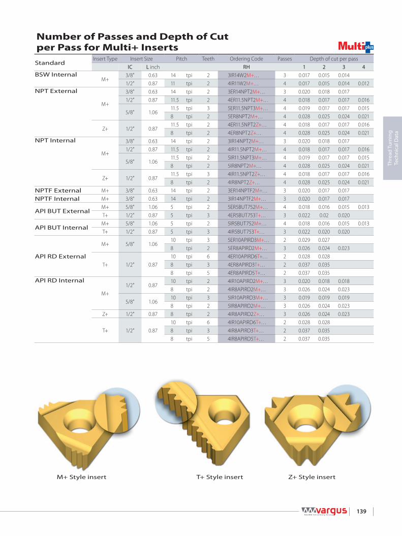
139
Thre
ad T
urni
ng
Tech
nica
l Dat
a
Number of Passes and Depth of Cut per Pass for Multi+ InsertsStandard
Insert Type Insert Size Pitch Teeth Ordering Code Passes Depth of cut per passIC L inch RH 1 2 3 4
BSW InternalM+
3/8" 0.63 14 tpi 2 3IR14W2M+… 3 0.017 0.015 0.0141/2" 0.87 11 tpi 2 4IR11W2M+… 4 0.017 0.015 0.014 0.012
NPT External
M+
3/8" 0.63 14 tpi 2 3ER14NPT2M+… 3 0.020 0.018 0.0171/2" 0.87 11.5 tpi 2 4ER11.5NPT2M+… 4 0.018 0.017 0.017 0.016
5/8" 1.0611.5 tpi 3 5ER11.5NPT3M+… 4 0.019 0.017 0.017 0.0158 tpi 2 5ER8NPT2M+… 4 0.028 0.025 0.024 0.021
Z+ 1/2" 0.8711.5 tpi 2 4ER11.5NPT2Z+… 4 0.018 0.017 0.017 0.0168 tpi 2 4ER8NPT2Z+… 4 0.028 0.025 0.024 0.021
NPT Internal
M+
3/8" 0.63 14 tpi 2 3IR14NPT2M+… 3 0.020 0.018 0.0171/2" 0.87 11.5 tpi 2 4IR11.5NPT2M+… 4 0.018 0.017 0.017 0.016
5/8" 1.0611.5 tpi 2 5IR11.5NPT3M+… 4 0.019 0.017 0.017 0.0158 tpi 2 5IR8NPT2M+… 4 0.028 0.025 0.024 0.021
Z+ 1/2" 0.8711.5 tpi 3 4IR11.5NPT2Z+… 4 0.018 0.017 0.017 0.0168 tpi 2 4IR8NPT2Z+… 4 0.028 0.025 0.024 0.021
NPTF External M+ 3/8" 0.63 14 tpi 2 3ER14NPTF2M+… 3 0.020 0.017 0.017NPTF Internal M+ 3/8" 0.63 14 tpi 2 3IR14NPTF2M+… 3 0.020 0.017 0.017
API BUT ExternalM+ 5/8" 1.06 5 tpi 2 5ER5BUT752M+… 4 0.018 0.016 0.015 0.013T+ 1/2" 0.87 5 tpi 3 4ER5BUT753T+… 3 0.022 0.02 0.020
API BUT InternalM+ 5/8" 1.06 5 tpi 2 5IR5BUT752M+… 4 0.018 0.016 0.015 0.013T+ 1/2" 0.87 5 tpi 3 4IR5BUT753T+… 3 0.022 0.020 0.020
API RD External
M+ 5/8" 1.0610 tpi 3 5ER10APIRD3M+… 2 0.029 0.0278 tpi 2 5ER8APIRD2M+… 3 0.026 0.024 0.023
T+ 1/2" 0.8710 tpi 6 4ER10APIRD6T+… 2 0.028 0.0288 tpi 3 4ER8APIRD3T+… 2 0.037 0.0358 tpi 5 4ER8APIRD5T+… 2 0.037 0.035
API RD Internal
M+1/2" 0.87
10 tpi 2 4IR10APIRD2M+… 3 0.020 0.018 0.0188 tpi 2 4IR8APIRD2M+… 3 0.026 0.024 0.023
5/8" 1.0610 tpi 3 5IR10APIRD3M+… 3 0.019 0.019 0.0198 tpi 2 5IR8APIRD2M+… 3 0.026 0.024 0.023
Z+ 1/2" 0.87 8 tpi 2 4IR8APIRD2Z+… 3 0.026 0.024 0.023
T+ 1/2" 0.8710 tpi 6 4IR10APIRD6T+… 2 0.028 0.0288 tpi 3 4IR8APIRD3T+… 2 0.037 0.0358 tpi 5 4IR8APIRD5T+… 2 0.037 0.035
M+ Style insert T+ Style insert Z+ Style insert

140
Thre
ad T
urni
ng
Tech
nica
l Dat
a
M40
x 2
.5
L
XY
IC
L
XY
IC
BF
L 2L 1
HH 1
Step by Step Thread Turning - Example 1
Choose the Thread Turning Method
Choose the Insert Size
Application:
Thread: External Right Hand 1½ x 10UNMaterial: 4140 (25 HRc)
Feed direction towards the chuck was chosen. Therefore, an external right hand insert and an external right hand holder will be used.
From the table, using a pitch of 10 tpi and a workpiece diameter of 1½ ", we find the helix angle to be 1.5°.
u
v
w
x
Chosen insert: 3ER10UN...
Insert Size Pitch Ordering Code Anvil Toolholder
IC L inch tpi RH RH
3/8” 0.63 10 3ER10UN... YE3 AL..-3(LH)
Choose the Toolholder
Chosen toolholder: AL 100-3
Insert Size Ordering Code Dimensions inch
IC RH H=H1=B F L1 L2
3/8” AL 100-3 1.00 1.00 6.05 1.20
5° 4° 3° =1°β=2°β
D
1
2
3
4
5
6
7
8
9
11
10
12
2 4
2.5
3
3.5
44.5567911141824
=0°β
2.25
6 80
SpecialToolholders
Pitch P*[mm]
Pitch P*[tpi]
Pitch diameter [inch]

141
Thre
ad T
urni
ng
Tech
nica
l Dat
a
y
U
V
Choose the Correct Anvil
Anvil chosen: YE3 Resultant Helix Angle 3.5 2.5 1.5 0.5 Insert Size Ordering Code Holder Ordering Code
IC L inch 3/8” 0.63 ER/IL YE3-2P YE3-1P YE3 YE3-1N
Choose the carbide grade and cutting speedCarbide Grade chosen: VTXCutting Speed: 420 ft/min Material: Hardness
Brinell HB VTX VCB
P Low alloy steel(alloying elements ≤ 5%)
Non hardened 180 279-476 328-590Hardened 275 246-459 246-459Hardened 350 230-443 230-443
Determine the Number of PassessNumbers of passes: 10
UN External
Pitch mm 1.50 1.75 2.00 2.50 3.00 3.50 4.00
tpi 16 14 12 10 8 7 6
No. of passes 6-10 7-12 7-12 8-14 9-16 10-18 11-18
Summary
Thread Type 1½x10UN External Right Hand
u Feed Direction: Towards the chuck
v Insert and Grade: 3ER10UN VTX
w Toolholder: AL 100 - 3
x Helix Angle: 1.5°
y Anvil: YE3
U Cutting Speed: 420 ft/min
V Number of Passes: 10
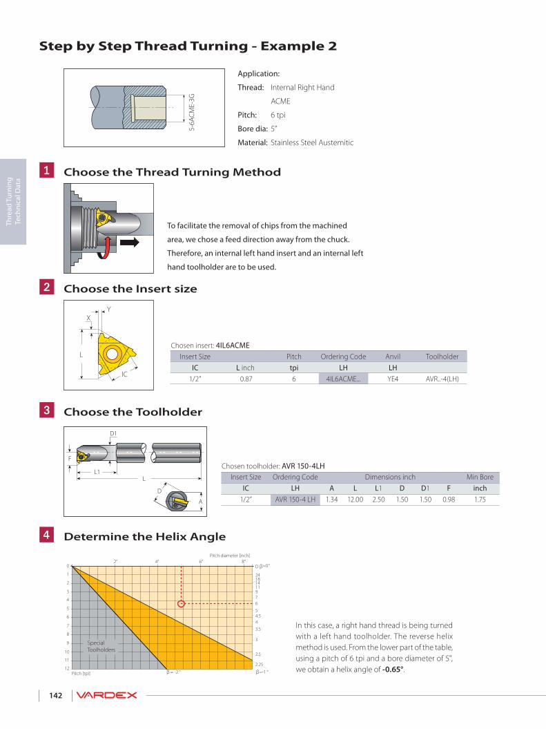
142
Thre
ad T
urni
ng
Tech
nica
l Dat
a
5-6A
CME-
3G
L
XY
IC
Application:
Thread: Internal Right Hand
ACME
Pitch: 6 tpi
Bore dia: 5”
Material: Stainless Steel Austemitic
To facilitate the removal of chips from the machined
area, we chose a feed direction away from the chuck.
Therefore, an internal left hand insert and an internal left
hand toolholder are to be used.
Step by Step Thread Turning - Example 2
Choose the Thread Turning Method
Choose the Insert size
Choose the Toolholder
Determine the Helix Angle
u
v
w
x
Chosen insert: 4IL6ACMEInsert Size Pitch Ordering Code Anvil Toolholder
IC L inch tpi LH LH1/2” 0.87 6 4IL6ACME... YE4 AVR..-4(LH)
Chosen toolholder: AVR 150-4LHInsert Size Ordering Code Dimensions inch Min Bore
IC LH A L L1 D D1 F inch1/2” AVR 150-4 LH 1.34 12.00 2.50 1.50 1.50 0.98 1.75
D1
F
LL1
A
D
In this case, a right hand thread is being turned with a left hand toolholder. The reverse helix method is used. From the lower part of the table, using a pitch of 6 tpi and a bore diameter of 5", we obtain a helix angle of -0.65°.
D
1
2
3
4
5
6
7
8
9
11
10
12
2” 4”
2.5
3
3.544.55
67911141824
=-1 °
=0°
β
β
β = -2 °
2.25
6” 8”0
SpecialToolholders
Pitch diameter [inch]
Pitch [tpi]

143
Thre
ad T
urni
ng
Tech
nica
l Dat
a
Summary
Thread Type 5”x6 ACME Internal Right Hand
u Feed Direction: Away from the chuck
v Insert and Grade: 4IL6ACME VTX
w Toolholder: AVR 150-4LH
x Helix Angle: -0.65°
y Anvil: YE4-2N
U Cutting Speed: 420 ft/min
V Number of Passes: 18
y
U
V
Choose the Correct Anvil
Anvil chosen: YE4-2N Resultant Helix Angle 1.5 0.5 0 -0.5 -1.5Insert Size Ordering Code
IC L inch 1/2” 0.87 ER/IL YE4 YE4-1N YE4-1.5N YE4-2N YE4-3N
Carbide grade chosen: VTXCutting speed: 420 ft/min Material: Hardness
Brinell HB VTX VCB
M Stainless steelAustenitic
Austenitic 180 295-459 266-394Super austenitic 200 131-361 98-328
Determine The Number Of PassessNumbers of passes: 18
ACME External & Internal
Pitch mm 3.00 3.50 4.00 4.50 5.00 5.50 6.00
tpi 8 7 6 5.5 5 4.5 4
No. of passes 9-16 10-18 11-18 11-19 12-20 12-20 12-20
Choose the carbide grade and cutting speed

144
Thre
ad T
urni
ng
Tech
nica
l Dat
a
Material Comparison TableMaterialGroup
VardexNo.
USA AISI/SAE
Germany W.-Nr.
Germany DIN
Great Britain BS
France AFNOR
ItalyUNI
PSteel
1 1015 1.0037 St37-2 Fe360B E24-2 Fe360 B FU1 1020 1.0044 St44-2 Fe430B FN E28-2 Fe430B FN2 ASTM A570Gr.50 1.0050 St50-2 Fe490-2 FN A50-2 Fe4902 – 1.0070 St70-2 Fe690-2 FN A70-2 Fe6901 1015 1.0401 C15 080M15 CC12 C15C161 1020 1.0402 C22 050A20 CC20 C20C212 1035 1.0501 C35 060A35 CC35 C352 1045 1.0503 C45 080M46 CC45 C452 1055 1.0535 C55 070M55 – C552 1060 1.0601 C60 080A62 CC55 C601 1213 1.0715 9SMn28 230M07 S250 CF9SMn281 12L13 1.0718 9SMnPb28 – S250Pb CF9SMnPb281 – 1.0722 10SPb20 – 10PbF2 CF10SPb202 1140 1.0726 35S20 212M36 35MF4 –2 1215 1.0736 9SMn36 240M07 S300 CF9SMn362 12L14 1.0737 9SMnPb36 – S300Pb CF9SMnPb362 9255 1.0904 55Si7 250A53 55S7 55Si82 9262 1.0961 60SiCr7 – 60SC7 60SiCr81 1015 1.1141 Ck15 080M15 XC1 2 C162 1039 1.1157 40Mn4 150M36 35M5 –2 1025 1.1158 Ck25 – – –2 1335 1.1167 36Mn5 – 40M5 –2 1330 1.1170 28Mn6 150M28 20M5 C28Mn2 1035 1.1183 Cf35 060A35 XC38TS C362 1045 1.1191 Ck45 080M46 XC42 C452 1055 1.1203 Ck55 070M55 XC55 C503 1050 1.1213 Cf53 060A52 XC48TS C533 1060 1.1221 Ck60 080A62 XC60 C608 1095 1.1274 Ck101 060A96 – –9 – 1.3401 X120Mn12 Z120M12 Z120M12 XG120Mn128 52100 1.3505 100Cr6 534A99 100C6 100Cr68 ASTM A20Gr.A 1.5415 15Mo3 1501-240 15D3 16Mo3KW8 4520 1.5423 16Mo5 1503-245-420 – 16Mo54 ASTMA350LF5 1.5622 14Ni6 – 16N6 14Ni68 ASTM A353 1.5662 X8Ni9 1501-509; 510 – X10Ni98 2515 1.5680 12Ni19 – Z18N5 –5 3135 1.5710 36NiCr6 640A35 35NC6 –5 3415 1.5732 14NiCr10 – 14NC11 16NiCr115 3415; 3310 1.5752 14NiCr14 655M13; 655M12 12NC15 –5 9840 1.6511 36CrNiMo4 816M40 40NCD3 38NiCrMo4(KB)5 8620 1.6523 21NiCrMo2 805M20 20NCD2 20NiCrMo25 8740 1.6546 40NiCrMo22 311-Type7 – 40NiCrMo2(KB)5 4340 1.6582 34CrNiMo6 817M40 35NCD6 35NiCrMo6(KB)5 – 1.6587 17CrNiMo6 820A16 18NCD6 –5 – 1.6657 14NiCrMo134 832M13 – 15NiCrMo132 5015 1.7015 15Cr3 523M15 12C3 –5 5132 1.7033 34Cr4 530A32 32C4 34Cr4(KB)5 5140 1.7035 41Cr4 530M40 42C4 41Cr45 5140 1.7045 42Cr4 – – –5 5115 1.7131 16MnCr5 (527M20) 16MC5 16MnCr55 5155 1.7176 55Cr3 527A60 55C3 –5 4130 1.7218 25CrMo4 1717CDS110 25CD4 25CrMo4(KB)5 4137; 4135 1.7220 34CrMo4 708A37 35CD4 35CrMo45 4140; 4142 1.7223 41CrMo4 708M40 42CD4TS 41CrMo45 4140 1.7225 42CrMo4 708M40 42CD4 42CrMo45 – 1.7262 15CrMo5 – 12CD4 –5 ASTM A182; F11; F12 1.7335 13CrMo4 4 1501-620Gr.27 15CD3.5; 15CD4.5 14CrMo4 55 – 1.7361 32CrMo12 722M24 30CD12 32CrMo125 ASTM A182; F22 1.7380 10CrMo9 10 1501-622; Gr.31; 45 12CD9; 10 12CrMo9, 105 – 1.7715 14MoV6 3 1503-660-440 – –5 6150 1.8159 50CrV4 735A50 50CV4 50CrV48 – 1.8509 41CrAIMo7 905M39 40CAD6, 12 41CrAIMo78 – 1.8523 39CrMoV13 9 897M39 – 36CrMoV125 W.110 1.1545 C105W1 – Y1105 C98KU; C100KU5 W.112 1.1663 C125W – Y2120 C120KU8 L3 1.2067 100Cr6 BL3 Y100C6 –10 D3 1.2080 X210Cr12 BD3 Z200Cr12 X210Cr13KU10 – – – – – X250Cr12KU10 – 1.2311 40CrMnMo7 – – 35CrMo8KU10 – 1.2312 40CrMnMoS8-6 – – –10 H11 1.2343 X38CrMoV5-1 BH11 Z38CDV5 X37CrMoV51 1KU10 H13 1.2344 X40CrMoV5-1 BH13 Z40CDV5 X35CrMoV05KU10 – – – – – X40CrMoV511KU10 A2 1.2363 X100CrMoV5-1 BA2 Z1 00CDV5 X100CrMoV51KU10 – 1.2367 X38CrMoV5-3 – Z38CDV5-3 –10 D2 1.2379 X155CrVMo 12-1 BD2 Z160CDV12 X155CrVMo12 1 KU10 – 1.2419 105WCr6 – 105WC13 10WCr6; 107WCr5KU10 – 1.2436 X210CrW12 – – X215CrW121KU10 S1 1.2542 45WCrV17 BS1 – 45WCrV8KU10 H21 1.2581 X30WCrV9 3 BH21 Z30WCV9 X30WCrV9 3KU10 – 1.2601 X165CrMoV12 – – X165CrMoW12KU10 L6 1.2713 55NiCrMoV6 – 55NCDV7 –10 – 1.2738 40CrMnNiMo8-6-4 – – –10 W210 1.2833 100V1 BW2 Y1105V; 100V2 –10 – 1.3243 S 6-5-2-5 – Z85WDKCV-06-05-05-04-02 HS 6-5-2-510 T4 1.3255 S 18-1-2-5 BT4 Z80WKCV-18-05-04-01 X78WCo1805KU10 M2 1.3343 S 6-5-2 BM2 Z85WDCV-06-05-04-02 X82WMo0605KU10 M7 1.3348 S 2-9-2 – Z100WCWV-09-04-02-02 HS 2-9-210 T1 1.3355 S 18-0-1 BT1 Z80WCV-18-04-01 X75W18KU
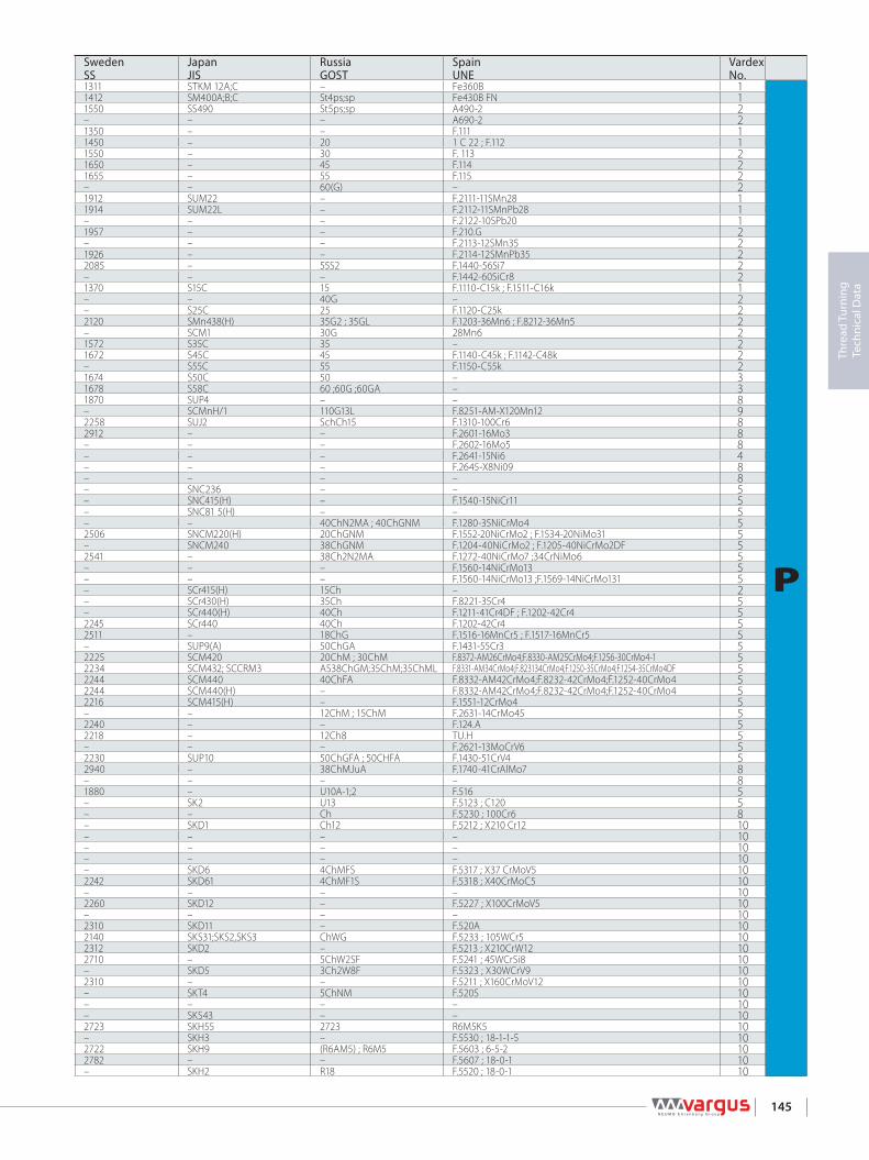
145
Thre
ad T
urni
ng
Tech
nica
l Dat
a
Sweden SS
Japan JIS
Russia GOST
Spain UNE
VardexNo.
1311 STKM 12A;C – Fe360B 1
P
1412 SM400A;B;C St4ps;sp Fe430B FN 11550 SS490 St5ps;sp A490-2 2– – – A690-2 21350 – – F.111 11450 – 20 1 C 22 ; F.112 11550 – 30 F. 113 21650 – 45 F.114 21655 – 55 F.115 2– – 60(G) – 21912 SUM22 – F.2111-11SMn28 11914 SUM22L – F.2112-11SMnPb28 1– – – F.2122-10SPb20 11957 – – F.210.G 2– – – F.2113-12SMn35 21926 – – F.2114-12SMnPb35 22085 – 55S2 F.1440-56Si7 2– – – F.1442-60SiCr8 21370 S15C 15 F.1110-C15k ; F.1511-C16k 1– – 40G – 2– S25C 25 F.1120-C25k 22120 SMn438(H) 35G2 ; 35GL F.1203-36Mn6 ; F.8212-36Mn5 2– SCM1 30G 28Mn6 21572 S35C 35 – 21672 S45C 45 F.1140-C45k ; F.1142-C48k 2– S55C 55 F.1150-C55k 21674 S50C 50 – 31678 S58C 60 ;60G ;60GA – 31870 SUP4 – – 8– SCMnH/1 110G13L F.8251-AM-X120Mn12 92258 SUJ2 SchCh15 F.1310-100Cr6 82912 – – F.2601-16Mo3 8– – – F.2602-16Mo5 8– – – F.2641-15Ni6 4– – – F.2645-X8Ni09 8– – – – 8– SNC236 – – 5– SNC415(H) – F.1540-15NiCr11 5– SNC81 5(H) – – 5– – 40ChN2MA ; 40ChGNM F.1280-35NiCrMo4 52506 SNCM220(H) 20ChGNM F.1552-20NiCrMo2 ; F.1534-20NiMo31 5– SNCM240 38ChGNM F.1204-40NiCrMo2 ; F.1205-40NiCrMo2DF 52541 – 38Ch2N2MA F.1272-40NiCrMo7 ;34CrNiMo6 5– – – F.1560-14NiCrMo13 5– – – F.1560-14NiCrMo13 ;F.1569-14NiCrMo131 5– SCr415(H) 15Ch – 2– SCr430(H) 35Ch F.8221-35Cr4 5– SCr440(H) 40Ch F.1211-41Cr4DF ; F.1202-42Cr4 52245 SCr440 40Ch F.1202-42Cr4 52511 – 18ChG F.1516-16MnCr5 ; F.1517-16MnCr5 5– SUP9(A) 50ChGA F.1431-55Cr3 52225 SCM420 20ChM ; 30ChM F.8372-AM26CrMo4;F.8330-AM25CrMo4;F.1256-30CrMo4-1 52234 SCM432; SCCRM3 AS38ChGM;35ChM;35ChML F.8331-AM34CrMo4;F.823134CrMo4;F.1250-35CrMo4;F.1254-35CrMo4DF 52244 SCM440 40ChFA F.8332-AM42CrMo4;F.8232-42CrMo4;F.1252-40CrMo4 52244 SCM440(H) – F.8332-AM42CrMo4;F.8232-42CrMo4;F.1252-40CrMo4 52216 SCM415(H) – F.1551-12CrMo4 5– – 12ChM ; 15ChM F.2631-14CrMo45 52240 – – F.124.A 52218 – 12Ch8 TU.H 5– – – F.2621-13MoCrV6 52230 SUP10 50ChGFA ; 50CHFA F.1430-51CrV4 52940 – 38ChMJuA F.1740-41CrAlMo7 8– – – – 81880 – U10A-1;2 F.516 5– SK2 U13 F.5123 ; C120 5– – Ch F.5230 ; 100Cr6 8– SKD1 Ch12 F.5212 ; X210 Cr12 10– – – – 10– – – – 10– – – – 10– SKD6 4ChMFS F.5317 ; X37 CrMoV5 102242 SKD61 4ChMF1S F.5318 ; X40CrMoC5 10– – – – 102260 SKD12 – F.5227 ; X100CrMoV5 10– – – – 102310 SKD11 – F.520A 102140 SKS31;SKS2,SKS3 ChWG F.5233 ; 105WCr5 102312 SKD2 – F.5213 ; X210CrW12 102710 – 5ChW2SF F.5241 ; 45WCrSi8 10– SKD5 3Ch2W8F F.5323 ; X30WCrV9 102310 – – F.5211 ; X160CrMoV12 10– SKT4 5ChNM F.520S 10– – – – 10– SKS43 – – 102723 SKH55 2723 R6M5K5 10– SKH3 – F.5530 ; 18-1-1-5 102722 SKH9 (R6AM5) ; R6M5 F.5603 ; 6-5-2 102782 – – F.5607 ; 18-0-1 10– SKH2 R18 F.5520 ; 18-0-1 10
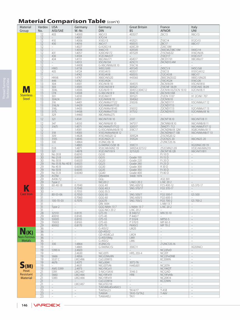
146
Thre
ad T
urni
ng
Tech
nica
l Dat
a
Material Comparison Table (con't)MaterialGroup
VardexNo.
USA AISI/SAE
Germany W.-Nr.
Germany DIN
Great Britain BS
France AFNOR
ItalyUNI
MStainless
Steel
12 403 1.4000 X6Cr13 403S17 Z6C13 X6Cr1312 – 1.4001 X7Cr14 – – –12 410 1.4006 X10Cr13 410S21 Z10C14 X12Cr1312 430 1.4016 X6Cr17 430S15 Z8C17 X8Cr1712 – 1.4027 G-X20Cr14 420C29 Z20C13M –12 – 1.4034 X46Cr13 420S45 Z40CM;Z38C13M X40Cr1412 431 1.4057 X20CrNi172 431S29 Z15CNi6.02 X16CrNi1612 430 1.4104 X12CrMoS17 – Z10CF17 X10CrS1712 434 1.4113 X6CrMo171 434S17 Z8CD17.01 X8CrMo1712 – 1.4313 X5CrNi134 425C11 Z4CND13.4M –12 – 1.4408 G-X6CrNiMo18 10 316C16 – –12 HW3 1.4718 X45CrSi93 401S45 Z45CS 9 X45CrSi812 405 1.4724 X10CrAI13 403S17 Z10C13 X101CrA11211 – 1.4742 X10CrAI18 430S15 Z12CAS18 X8Cr1712 HNV6 1.4747 X80CrNiSi20 443S65 Z80CSN20.02 X80CrSiNi2011 446 1.4762 X10CrAI24 – Z10CAS24 X16Cr2613 304 1.4301 X5CrNi18 10 304S15 Z6CN18.09 X5CrNi181013 303 1.4305 X10CrNiS18 9 303S21 Z10CNF 18.09 X10CrNiS 18.0913 304L 1.4306 X2CrNi19 11 304S12;304C12 Z2CN18.10;Z3CN 19.10 X2CrNi18.1113 CF8 1.4308 G-X6CrNi18 9 304C15 Z6CN18.10M –13 301 1.4310 X12CrNi177 301S21 Z12CN 17.07 X1 2CrNi1 70713 304LN 1.4311 X2CrNiN18 10 304S62 Z2CN18.10 –13 316 1.4401 X5CrNiMo17122 316S16 Z6CND17.11 X5CrNiMo17 1213 316LN 1.4429 X2CrNiMoN17133 – Z2CND17.13 –13 316L 1.4435 X2CrNiMo18143 316S12 Z2CND17.13 X2CrNiMo17 1313 317L 1.4438 X2CrNiMo17133 317S12 Z2CND19.15 X2CrNiMo18 1613 329 1.4460 X8CrNiMo275 – – –
12 321 1.4541 X6CrNiTi18 10 2337 Z6CNT18.10 X6CrNiTi18 11
12 347 1.4550 X6CrNiNb18 10 347S17 Z6CNNb18.10 X6CrNiNb18 1112 316Ti 1.4571 X6CrNiMoTi17122 320S17 Z6NDT1 7.12 X6CrNiMoTi17 1212 – 1.4581 G-X5CrNiMoNb18 10 318C17 Z4CNDNb18 12M XG8CrNiMo18 1112 318 1.4583 X10CrNiMoNb18 12 – Z6CNDNb17 13B X6CrNiMoNb17 1313 309 1.4828 X15CrNiSi20 12 309S24 Z15CNS20.12 –13 310S 1.4845 X12CrNi25 21 310S24 Z12CN25 20 X6CrNi25 2013 330 1.4864 X12NiCr36 16 – Z12NCS35.16 –13 – 1.4865 G-X40NiCrSi38 18 330C11 – XG50NiCr39 1913 EV8 1.4871 X53CrMnNiN2 19 349S54;321S12 Z52CMN21.09 X53CrMnNiN21913 321 1.4878 X12CrNiTi18 9 321S320 Z6CNT18.12B X6CrNiTi1811
KCast Iron
30 No 20 B 0.6010 GG10 – Ft 10 D –30 No 25 B 0.6015 GG15 Grade 150 Ft 15 D –30 No 30 B 0.6020 GG20 Grade 220 Ft 20 D –29 No 35 B; No 40 B 0.6025 GG25 Grade 260 Ft 25 D –29 No 45 B 0.6030 GG30 Grade 300 R 30 D –29 No 50 B 0.6035 GG35 Grade 350 Ft 35 D –29 No 55 B 0.6040 GG40 Grade 400 Ft 40 D –29 ASTM – DIN4694 3468: 1974 – –29 A436-72 – GGL- A32-30129 Type 2 – NiCr20 2 L-NiCr 20 2 L-NC 20 2 –30 60-40-18 0.7040 GGG 40 SNG 420/12 FCS 400-12 GS 370-1730 – 0.7043 GGG 40.3 SNG 370/17 FGS 370-17 –30 – 0.7033 GGG 35.3 – – –31 80-55-06 0.7050 GGG 50 SNG 500/7 FGS 500-7 GS 50031 – 0.7060 GGG 60 SNG 600/3 FGS 600-3 –31 100-70-03 0.7070 GGG70 SNG 700/2 FGS 700-2 GS 700-231 – – DIN 1694 – L-NM 13 7 –31 Type 2 – GGG NiMn 13 7 L-NiMn 13 7 L-NC 20 2 –31 – – GGG NiCr 20 2 L-NC 20 2 – –28 32510 0.8135 GTS-35 B 340/12 MN 35-10 –29 40010 0.8145 GTS-45 P 440/7 – –29 50005 0.8155 GTS-55 P 510/4 MP50-5 –29 70003 0.8165 GTS-65 P 570/3 MP 60-3 –29 80002 0.8170 GTS-70 P690/2 MP 70-2 –
N(K)Non-Ferrous
Metals
36 – – G-AlSi12 LM20 – –36 – – GD-AlSi12 – – –36 – – GD-AlSi8Cu3 LM24 – –36 – – G-AlSi10Mg LM9 – –36 – – G-AlSi12 LM6 – –
S(M)Heat
Resistant Material
19 330 1.4864 X12NiCrSi – Z12NCS35.16 –19 – 1.4865 G-X40NiCrSi 330C11 – XG50NiCr 19 5390 A 2.4603 – – NC22FeD –19 – 2.4630 NiCr20Ti HR5, 203-4 NC20T –19 5666 2.4856 NiCr22Mo9N – NC22FeDNB –19 5537 C LW2.496 CoCr20W15 – KC20WN –19 4676 2.4375 NiCu30Al 3072-76 – –19 – 2.4631 NiCr20TiAk Hr40,601 NC20TA –19 AMS 5399 2.4973 NiCr19Co11 – NC19KDT –21 5391 LW2.467 S-NiCr13A16 3146-3 NC12AD –21 5660 LW2.466 NiCr19Fe19 HR8 NC19FeNb –21 5383 LW2.466 NiCr19Fe19 – NC20K14 –21 – – CoCr22W14 – KC22WN –21 – LW2.467 NiCo15Cr10 – – –23 – – TiAl14Mo4Sn4Si0.5 – – –23 – – TiAl5Sn2.5 TA14/17 T-A5E –23 – – TiAl6V4 TA10-13/TA2 T-A6V –23 – – TiAl6V4ELI TA11 – –

147
Thre
ad T
urni
ng
Tech
nica
l Dat
a
Sweden SS
Japan JIS
Russia GOST
Spain UNE
VardexNo.
2301 SUS403 08Ch13 F.3110-X6Cr13 ; F.8401-AM-X12Cr13 12
M
– – 08Ch13 F.3110-X6Cr13 ; F.8401-AM-X12Cr13 122302 SUS410 12Ch13 ; 15Ch13L F.3401-X10Cr13 122320 SUS430 12Ch17 F.3113-X6Cr17 12– SCS2 20Ch13L – 122304 SUS420J2 40Ch13 F.3405-X45Cr13 122321 SUS431 20Ch17N2 F.3427-X19CrNi172 122383 SUS430F – F.3117-X10CrS17 ; F.3413-X14CrMoS17 122325 SUS434 – F.3116-X6CrMo171 12– SCS5 – – 12– SCS14 07Ch18N10G2S2M2L F.8414-AM-X7CrNiMo2010 12– SUH1 40Ch9S2 F.3220-X4SCrSi09-03 12– SUS405 10Ch13SJu F.3152-X10CrAl13 12– SUH21 15Ch18SJu F.3153-X10CrAl18 11– SUH4 – F.3222-X80CrSiNi20-02 122322 SUH446 – F.3154-X10CrAl24 112332 SUS304 08Ch18N10 F.3551-X5CrNi1811;F.3541-X5CrNi1810 ; F.3504-X6CrNi1910 132346 SUS303 – F.3508-X10CrNiS18-09 132352 SCS19; SUS304L 03Ch18N11 F.3503-X2CrNi1810 132333 SCS13 07Ch18N9L – 132331 SUS301 – F.3517-X12CrNi177 132371 SUS304LN – F.3541-X2CrNiN1810 132347 SUS316 – F.3534-X5CrNiMo17122 132375 SUS316LN – F.3543-X2CrNiMoN17133 132353 SCS16 03Ch17N14M3 F.3533-X2CrNiMo17132 132367 SUS317L – F.3539-X2CrNiMo18164 132324 SUS329L; – F.3309-X8CrNiMo27-05; F.3552-X8CrNiMo266 1358B SUS321 06Ch18N10T; 08Ch18N10T09;
Ch18N10T; 12Ch18N10T F.3523-X6CrNiTi1810 122338 SUS347 08Ch18N12B F.3524-X6CrNiNb1810 122350 – 10Ch17N13M2T F.3535-X6CrNiMoTi17122 12– SCS22 – – 12– – – – 12– SUH309 20Ch20N14S2 F.3312-X15CrNiSi20-12 132361 SUH310 20Ch23N18 – 13– SUH330 – F.3313-X12CrNiSi36-16 13– SCH15 – – 13– SUH35,SUH36;SU321 55Ch20G9AN4 F.3217-X53CrMnNiN21-09 13– – – – 13
K
01 10 – CЧ10 FG10 3001 15 – CЧ15 FG15 3001 20 – CЧ20 FG20 3001 25 – CЧ25 FG25 2901 30 – CЧ30 FG30 2901 35 – CЧ35 FG35 2901 40 – CЧ40 – 29MB – – – 29ISO-215 – – 29523 – – – 2907 17-02 – VC42-12 – 3007 17-12 – VC42-12 – 3007 17-15 – – – 3007 27-02 – VC50-2 – 3107 32-03 – VC60-2 – 3107 37-01 – VC70-2 – 3107 72 – – – 3107 76 – – – 31– – – – 3108 15 – – – 2808 52 – – – 2908 54 – – – 2908 58 – – – 2908 62 – – – 294260 – – – 36
N4247 – – – 364250 – – – 364253 – – – 364261 – – – 36– SUH 330 – F.3313-X12CrNiSi36-16 19
S
– SCH 15 – – 19– – – – 19– – – – 19– – – – 19– – – – 19– – – – 19– – – – 19– – – – 19– – – – 21– – – – 21– – – – 21– – – – 21– – – – 21– – – – 23– – – – 23– – – – 23– – – – 23

148
Thre
ad T
urni
ng
Tech
nica
l Dat
a
Troubleshooting
Problem Possible Cause Solution
Increasedflank wear
Cutting speed too high ---------------------------➤
Depth of cut too low/ too many passes --------➤
Unsuitable carbide grade -------------------------➤
Insufficient cooling --------------------------------➤
Reduce cutting speed/ use coated insert
Increase the depth of cut per pass
Use a coated carbide grade
Increase coolant flow rate
Uneven cutting edge wear
Incorrect helix angle -------------------------------➤
Wrong infeed method ----------------------------➤
Choose the correct anvil
Use the alternating flank infeed method
Extreme plasticdeformation
Depth of cut too large -----------------------------➤
Insufficient cooling --------------------------------➤
Cutting speed too high ---------------------------➤
Unsuitable carbide grade -------------------------➤
Nose radius too small ------------------------------➤
Decrease depth of cut/ increase number of passes
Increase coolant flow rate
Reduce cutting speed
Use a tougher carbide
Use an insert with a larger radius, if possible
Cutting edgebreakage
Depth of cut too large -----------------------------➤
Extreme plastic deformation ---------------------➤
Insufficient cooling --------------------------------➤
Unsuitable carbide grade -------------------------➤
Instability -------------------------------------------➤
Decrease depth of cut/ increase number of passes
Use a tougher carbide
Increase flow rate and/ or correct flow direction
Use a tougher carbide
Check stability of the system
Built-up edge
Incorrect cutting speed ---------------------------➤
Unsuitable carbide grade -------------------------➤
Change the cutting speed
Use a coated carbide
Thread profile is too shallow
The tool is not at the workpiece axis height ---➤
Insert is not machining the thread crest -------➤
Worn insert -----------------------------------------➤
Change tool height
Measure the workpiece diameter
Change the cutting edge sooner
Poor surface quality
Cutting speed too low ----------------------------➤
Wrong anvil -----------------------------------------➤
Flank infeed method is not appropriat ---------➤
Increase cutting speed
Choose correct anvil
Use the alternate flank or radial infeed method

> Inserts
Grooving

150
Gro
ovin
g In
sert
s
VARDEX Ordering Code System ...............................................................................................................................................Page 151
External - DIN 471 Retaining Ring Grooves for Shafts ................................................................................................Page 152
Internal - DIN 472 Retaining Ring Grooves for Bores ..................................................................................................Page 153
Internal - DIN 472 Retaining Ring Grooves for Bores-Micro ...................................................................................Page 154
External/Internal - CIRCLIP ...........................................................................................................................................................Page 156
Internal - CIRCLIP - MICRO ...........................................................................................................................................................Page 157
External/Internal - DIN 7993 Snap Ring Grooves ..........................................................................................................Page 159
External/Internal - DIN 7993 Snap Ring Grooves - Micro .........................................................................................Page 160
External - DIN 76 Thread Undercuts ......................................................................................................................................Page 161
Internal - DIN 76 Thread Undercuts .......................................................................................................................................Page 162
Internal - DIN 3770 - Grooves - Micro ...................................................................................................................................Page 162
SNAP RING .............................................................................................................................................................................................Page 163
Internal - CIRCLIP - Face Grooves - Micro ...........................................................................................................................Page 164
GROOVING INSERTS

151
Gro
ovin
g In
sert
s
51
L2
I3
R4
1.15
-6
D4727
-6
1.38
VKP9
1- Insert Size
5.0L - IC5.0L2 - IC1/4”3 - IC3/8”4 - IC1/2”5 - IC5/8”
5 - Groove Std. Width0.03 - 0.08 (inch)
2 - Insert Style
6 - Profile StyleC - Full Profile
3 - Type of Insert
E - ExternalI - Internal
7 - Groove Standard
DIN 471 PartialDIN 471DIN 472 PartialDIN 472 DIN 7993 PartialDIN 7993DIN 76 ST, DIN 76 SHDIN 3770
4 - RH / LH Insert
R - Right Hand InsertL - Left Hand Insert
8 - Groove Depth0.013 - 0.079 (inch)
9 - Carbide Grade
VTXVKP (for Mini)VHX (for Mini)
L
4.01
S2
I3
R4
0905
S6
- D4727
- 1.18
VMX9
1- Insert Dia.
3.0 - 3.0 mm4.0 - 4.0 mm6.0 - 6.0 mm8.0 - 8.0 mm10.0 - 10.0 mm
2 - Insert StyleS - Micro Insert
6 - Insert Length
A - AxialyS - ShortM - MediumL - Long
3 - Type of InsertI - Internal
4 - RH / LH Insert
R - Right Hand InsertL - Left Hand Insert
5 -Groove std. Width
0.027 - 0.078 (inch)0.90 - 2.15 (mm)
7 - Groove Standard
DIN 471DIN 472 CIRCLIPDIN 7993DIN 76SH, DIN 76STDIN 3770S, DIN 3770DSNAP RINGCIRCLIP - Face Grooving
8 - Groove Depth0.02 - 0.06 (inch)
9 - Carbide GradeVMX
I C
Vardex Ordering Code SystemGrooving Insert
Grooving Micro Insert - Double Ended

152
Gro
ovin
g In
sert
s
Standard (Partial Profile)Insert Size Ordering Code Groove Std. Dimensions inch Anvil Holder
IC RH m (H13) W t
3/8”
3ER1.10-D471-1.30... 0.043 0.047 0.051
YE3M-1.5N AL..-33ER1.30-D471-1.50... 0.051 0.055 0.0593ER1.60-D471-1.85... 0.063 0.067 0.0713ER1.85-D471-2.00... 0.073 0.076 0.079
Range of profiles also available on IC 1/4”, 1/2” and 5/8”, inserts on request.
Standard (Full Profile)Insert Size Ordering Code Groove Std. Dimensions inch Anvil Holder
IC RH m(H13) d1 W t1 t
3/8”
3ER1.10C-D471-0.35... 0.043 0.59 0.047 0.013 0.014
YE3M-1.5N AL..-3
3ER1.10C-D471-0.40... 0.043 0.63-0.67 0.047 0.014 0.0163ER1.30C-D471-0.50... 0.051 0.71-0.87 0.055 0.017 0.0203ER1.30C-D471-0.55... 0.051 0.94-1.02 0.055 0.018 0.0223ER1.60C-D471-0.70... 0.063 1.1-1.18 0.067 0.024 0.0283ER1.60C-D471-0.85... 0.063 1.26-1.34 0.067 0.030 0.0333ER1.60C-D471-1.00... 0.063 1.38 0.067 0.033 0.0393ER1.85C-D471-1.00... 0.073 1.42-1.50 0.076 0.033 0.0393ER1.85C-D471-1.25... 0.073 1.57-1.89 0.076 0.043 0.0493ER2.15C-D471-1.50... 0.085 1.97-2.48 0.088 0.053 0.059
Range of profiles also available on IC 1/4”, 1/2” and 5/8”, inserts on request.
m
d1
t
I C
Wt
t1
45°
W
I C
DIN 471 Retaining Ring Grooves for Shafts
External
Standard(Partial Profile)
Standard(Full Profile)

153
Gro
ovin
g In
sert
s
Standard (Partial Profile)Insert Size Ordering Code Groove Std. Dimensions inch Anvil Holder
IC m (H13) W t
3/8”
3IR1.10-D472-1.30... 0.043 0.047 0.051
YI3M-1.5N AVR..-33IR1.30-D472-1.50... 0.051 0.055 0.0593IR1.60-D472-1.80... 0.063 0.067 0.0713IR1.85-D472-2.00... 0.073 0.076 0.079
Range of profiles also available on IC 1/4”, 1/2” and 5/8”, inserts on request.For minimum bore diameters, refer to page 167.
Standard (Full Profile)Insert Size Ordering Code Groove Std. Dimensions inch Anvil Holder
IC m (H13) d1 W t1 t
3/8”
3IR1.10C-D472-0.50... 0.043 0.71 - 0.87 0.047 0.014 0.020
YI3M-1.5N AVR..-3
3IR1.30C-D472-0.60... 0.051 0.94 - 1.02 0.055 0.017 0.0243IR1.30C-D472-0.70... 0.051 1.10 - 1.18 0.055 0.024 0.0283IR1.30C-D472-0.85... 0.051 1.22 - 1.34 0.055 0.030 0.0333IR1.60C-D472-0.85... 0.063 1.34 0.067 0.030 0.0333IR1.60C-D472-1.00... 0.063 1.38 - 1.50 0.067 0.033 0.0393IR1.85C-D472-1.25... 0.073 1.57 - 1.89 0.076 0.043 0.0493IR2.15C-D472-1.50... 0.085 1.97 - 2.48 0.088 0.053 0.059
Range of profiles also available on IC 1/4”, 1/2” and 5/8”, inserts on request.For minimum bore diameters, refer to page 167.
Mini-L (Partial Profile)Insert Size Ordering Code Groove Std. Dimensions inch Min. Bore dia. (inch) Holder
IC m (H13) W t
5.0L5LIR0.9-D472-0.7... 0.035 0.039 0.028
0.315 .NVR...-5L5LIR1.1-D472-1.0... 0.043 0.047 0.0395LIR1.3-D472-1.5... 0.051 0.055 0.051
I C
t
W
t
t1
45°
W
I CIC 5.0
W
t
m
d1
DIN 472 Retaining Ring Grooves for Bores
Internal
Standard(Partial Profile)
Standard(Full Profile)
Mini-L(Partial Profile)

154
Gro
ovin
g In
sert
s
Micro - Double EndedInsert dia. Ordering Code Groove Std. Dimensions inch Min. Bore dia.
Holderd (mm) RH m (H13) W L1 L B t F inch
3.0
3.0SIR0.90S-D472-0.5... 0.035 0.039 0.36 1.42
0.031 0.02 0.055 0.126 SMC..-3.03.0SIR0.90M-D472-0.5... 0.035 0.039 0.64 1.973.0SIR1.10S-D472-0.5... 0.043 0.047 0.36 1.423.0SIR1.10M-D472-0.5... 0.043 0.047 0.64 1.97
4.0
4.0SIR0.90S-D472-1.1... 0.035 0.039 0.36 1.42
0.055 0.043 0.075 0.161 SMC..-4.0
4.0SIR0.90M-D472-1.1... 0.035 0.039 0.64 1.974.0SIR0.90L-D472-1.1... 0.035 0.039 0.84 2.364.0SIR1.10S-D472-1.1... 0.043 0.047 0.36 1.424.0SIR1.10M-D472-1.1... 0.043 0.047 0.64 1.974.0SIR1.10L-D472-1.1... 0.043 0.047 0.84 2.364.0SIR1.30S-D472-1.1... 0.051 0.055 0.36 1.424.0SIR1.30M-D472-1.1... 0.051 0.055 0.64 1.974.0SIR1.30L-D472-1.1... 0.051 0.055 0.84 2.364.0SIR1.60S-D472-1.1... 0.063 0.067 0.36 1.424.0SIR1.60M-D472-1.1... 0.063 0.067 0.64 1.974.0SIR1.60L-D472-1.1... 0.063 0.067 0.84 2.36
6.0
6.0SIR0.90S-D472-1.5... 0.035 0.039 0.36 1.42
0.071 0.059 0.114 0.24 SMC..-6.0
6.0SIR0.90M-D472-1.5... 0.035 0.039 0.64 1.976.0SIR0.90L-D472-1.5... 0.035 0.039 0.84 2.366.0SIR1.10S-D472-1.5... 0.043 0.047 0.36 1.426.0SIR1.10M-D472-1.5... 0.043 0.047 0.64 1.976.0SIR1.10L-D472-1.5... 0.043 0.047 0.84 2.366.0SIR1.30S-D472-1.5... 0.051 0.055 0.36 1.426.0SIR1.30M-D472-1.5... 0.051 0.055 0.64 1.976.0SIR1.30L-D472-1.5... 0.051 0.055 0.84 2.366.0SIR1.60S-D472-1.5... 0.063 0.067 0.36 1.426.0SIR1.60M-D472-1.5... 0.063 0.067 0.64 1.976.0SIR1.60L-D472-1.5... 0.063 0.067 0.84 2.366.0SIR1.85S-D472-1.5... 0.073 0.076 0.36 1.426.0SIR1.85M-D472-1.5... 0.073 0.076 0.64 1.976.0SIR1.85L-D472-1.5... 0.073 0.076 0.84 2.366.0SIR2.15S-D472-1.5... 0.085 0.088 0.36 1.426.0SIR2.15M-D472-1.5... 0.085 0.088 0.64 1.976.0SIR2.15L-D472-1.5... 0.085 0.088 0.84 2.36
continued on next page
m
L
tBF
WL1d
DIN 472 Retaining Ring Grooves for Bores
Internal
RH-Double Ended

155
Gro
ovin
g In
sert
s
Micro - Double Ended (con't)
Insert dia. Ordering Code Groove Std. Dimensions inch Min. Bore dia.Holder
d (mm) RH m (H13) W L1 L B t F inch
8.0
8.0SIR1.10M-D472-2.0... 0.043 0.047 0.79 2.76 0.098 0.079
0.154 0.331 SMC..-8.0
8.0SIR1.30M-D472-2.0... 0.051 0.055 0.79 2.76 0.098 0.0798.0SIR1.60M-D472-2.5... 0.063 0.067 0.79 2.76 0.118 0.0988.0SIR1.85M-D472-2.5... 0.073 0.076 0.79 2.76 0.118 0.0988.0SIR2.15M-D472-3.0... 0.085 0.088 0.79 2.76 0.138 0.1188.0SIR2.65M-D472-3.5... 0.104 0.108 0.79 2.76 0.157 0.1388.0SIR3.15M-D472-3.5... 0.124 0.129 0.79 2.76 0.157 0.138
10.0
10.0SIR1.30M-D472-3.5... 0.051 0.055 0.98 3.15
0.157 0.138 0.193 0.409 SMC..-10.0
10.0SIR1.60M-D472-3.5... 0.063 0.067 0.98 3.1510.0SIR1.85M-D472-3.5... 0.073 0.076 0.98 3.1510.0SIR2.15M-D472-3.5... 0.085 0.088 0.98 3.1510.0SIR2.65M-D472-3.5... 0.104 0.108 0.98 3.1510.0SIR3.15M-D472-3.5... 0.124 0.129 0.98 3.1510.0SIR4.15M-D472-3.5... 0.163 0.169 0.98 3.1510.0SIR5.15M-D472-3.5... 0.203 0.208 0.98 3.15
m
L
tBF
WL1d
DIN 472 Retaining Ring Grooves for Bores (con't)
Internal
RH-Double Ended
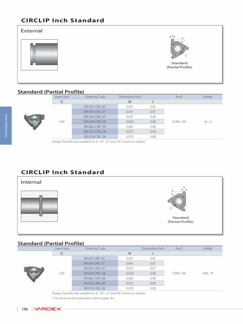
156
Gro
ovin
g In
sert
s
CIRCLIP Inch Standard
External
Standard(Partial Profile)
Standard (Partial Profile)Insert Size Ordering Code Dimensions Inch Anvil Holder
IC W t
3/8”
3ER.031-CIRC-.05 0.031 0.05
YE3M-1.5N AL..-3
3ER.041-CIRC-.07 0.041 0.073ER.047-CIRC-.07 0.047 0.083ER.058-CIRC-.08 0.058 0.083ER.062-CIRC-.08 0.062 0.083ER.072-CIRC-.08 0.072 0.083ER.078-CIRC-.08 0.078 0.08
Range of profiles also available on IC 1/4”, 1/2” and 5/8”, inserts on request.
CIRCLIP Inch Standard
Internal
Standard (Partial Profile)Insert Size Ordering Code Dimensions Inch Anvil Holder
IC W t
3/8”
3IR.031-CIRC-.05 0.031 0.05
YI3M-1.5N AVR..-3*
3IR.041-CIRC-.07 0.041 0.073IR.047-CIRC-.07 0.047 0.073IR.058-CIRC-.08 0.058 0.083IR.062-CIRC-.08 0.062 0.083IR.072-CIRC-.08 0.072 0.083IR.078-CIRC-.08 0.078 0.08
Range of profiles also available on IC 1/4”, 1/2” and 5/8”, inserts on request.
* For minimum bore diameters, refer to page 161.
t
I C
W
I C
t
W
Standard(Partial Profile)

157
Gro
ovin
g In
sert
s
CIRCLIP Inch Standard
Internal
Micro (Partial Profile)Insert dia. Dimensions Inch Min.
Bore dia.d mm RH-Double Ended W L1 L B t F Holder
3.0
3.0SIR.027S-CIRC-.02... 0.027 0.354 1.42
0.035 0.023
0.055 SMC0...-3.0 0.126
3.0SIR.027M-CIRC-.02... 0.027 0.63 1.973.0SIR.031S-CIRC-.02... 0.031 0.354 1.423.0SIR.031M-CIRC-.02... 0.031 0.63 1.973.0SIR.041S-CIRC-.02... 0.041 0.354 1.423.0SIR.041M-CIRC-.02... 0.041 0.63 1.973.0SIR.046S-CIRC-.04... 0.046 0.354 1.42
0.055 0.0433.0SIR.046M-CIRC-.04... 0.046 0.63 1.97
4.0
4.0SIR.027S-CIRC-.04... 0.027 0.354 1.42
0.055 0.043
0.074 SMC0...-4.0 0.165
4.0SIR.027M-CIRC-.04... 0.027 0.63 1.974.0SIR.027L-CIRC-.04... 0.027 0.827 2.364.0SIR.031S-CIRC-.04... 0.031 0.354 1.424.0SIR.031M-CIRC-.04... 0.031 0.63 1.974.0SIR.031L-CIRC-.04... 0.031 0.827 2.364.0SIR.041S-CIRC-.04... 0.041 0.354 1.424.0SIR.041M-CIRC-.04... 0.041 0.63 1.974.0SIR.041L-CIRC-.04... 0.041 0.827 2.364.0SIR.047S-CIRC-.04... 0.046 0.354 1.424.0SIR.047M-CIRC-.04... 0.046 0.63 1.974.0SIR.047L-CIRC-.04... 0.046 0.827 2.364.0SIR.058S-CIRC-.04... 0.058 0.354 1.424.0SIR.058M-CIRC-.04... 0.058 0.63 1.974.0SIR.058L-CIRC-.04... 0.058 0.827 2.364.0SIR.062S-CIRC-.06... 0.062 0.354 1.42
0.071 0.059
4.0SIR.062M-CIRC-.06... 0.062 0.63 1.974.0SIR.062L-CIRC-.06... 0.062 0.827 2.364.0SIR.078S-CIRC-.06... 0.078 0.354 1.424.0SIR.078M-CIRC-.06... 0.078 0.63 1.974.0SIR.078L-CIRC-.06... 0.078 0.827 2.36
continued on next page
L
tBF
WL1d
RH-Double Ended

158
Gro
ovin
g In
sert
s
CIRCLIP Inch Standard
Internal
Micro (Partial Profile) con’tInsert dia. Dimensions Inch Min.
Bore dia.d mm RH-Double Ended W L1 L B t F Holder
6.0
6.0SIR.046S-CIRC-.06... 0.046 0.354 1.42
0.071 0.059
0.114 SMC0...-6.0 0.244
6.0SIR.046M-CIRC-.06... 0.046 0.63 1.976.0SIR.046L-CIRC-.06... 0.046 0.827 2.366.0SIR.058S-CIRC-.06... 0.058 0.354 1.426.0SIR.058M-CIRC-.06... 0.058 0.63 1.976.0SIR.058L-CIRC-.06... 0.058 0.827 2.366.0SIR.062S-CIRC-.06... 0.062 0.354 1.426.0SIR.062M-CIRC-.06... 0.062 0.63 1.976.0SIR.062L-CIRC-.06... 0.062 0.827 2.366.0SIR.072S-CIRC-.06... 0.072 0.354 1.426.0SIR.072M-CIRC-.06... 0.072 0.63 1.976.0SIR.072L-CIRC-.06... 0.072 0.827 2.366.0SIR.078S-CIRC-.06... 0.078 0.354 1.426.0SIR.078M-CIRC-.06... 0.078 0.63 1.976.0SIR.078L-CIRC-.06... 0.078 0.827 2.366.0SIR.088S-CIRC-.06... 0.088 0.354 1.426.0SIR.088M-CIRC-.06... 0.088 0.63 1.976.0SIR.088L-CIRC-.06... 0.088 0.827 2.366.0SIR.094S-CIRC-.07... 0.094 0.354 1.426.0SIR.094M-CIRC-.07... 0.094 0.63 1.976.0SIR.094L-CIRC-.07... 0.094 0.827 2.36
0.079 0.069
6.0SIR.097S-CIRC-.07... 0.097 0.354 1.426.0SIR.097M-CIRC-.07... 0.097 0.63 1.976.0SIR.097L-CIRC-.07... 0.097 0.827 2.366.0SIR.105S-CIRC-.07... 0.105 0.354 1.426.0SIR.105M-CIRC-.07... 0.105 0.63 1.976.0SIR.105L-CIRC-.07.. 0.105 0.827 2.36
continued on next page
L
tBF
WL1d
RH-Double Ended

159
Gro
ovin
g In
sert
s
Standard (Partial Profile for Shafts)Insert Size Ordering Code Dimensions inch Anvil Holder
IC RH R W t
3/8”
3ER0.40-D7993-0.60... 0.015 0.031 0.024
YE3M-1.5N AL..-33ER0.60-D7993-0.80... 0.023 0.047 0.0313ER0.90-D7993-1.10... 0.035 0.071 0.0433ER1.00-D7993-1.20... 0.039 0.079 0.047
Range of profiles also available on IC 1/4”, 1/2” and 5/8”, inserts on request.
Standard (Partial Profile for Bores)Insert Size Ordering Code Dimensions inch Anvil Holder
IC RH R W t
3/8”3IR0.60-D7993-0.80... 0.023 0.047 0.031
YI3M-1.5N AVR..-33IR0.90-D7993-1.10... 0.035 0.071 0.0433IR1.00-D7993-1.20... 0.039 0.079 0.047
Range of profiles also available on IC 1/4”, 1/2” and 5/8” inserts on request.For minimum bore diameters, refer to page 167.
Mini-L (Partial Profile for Bores)Insert Size Ordering Code Dimensions inch Min. Bore dia. Holder
IC RH R W t inch
5.0L5LIR0.4-D7993-0.8... 0.016 0.031 0.031
0.315 .NVR...-5L5LIR0.6-D7993-1.0... 0.024 0.047 0.039
R
tIC
RW
R
t
IC
RW
IC 5.0 L
W
t
R
DIN 7993 Snap Ring Grooves
External
Standard(Partial Profile)
Internal
Standard(Partial Profile)
Mini-L (Partial Profile)

160
Gro
ovin
g In
sert
s
Micro (Partial Profile) - Double EndedInsert Dia. Ordering Code Groove Std. Dimensions inch Min. Bore dia.
Holderd (mm) RH R W L1 L B t F inch
3.03.0SIR0.4S-D7993-0.6... 0.016 0.031 0.36 1.42
0.031 0.024 0.055 0.126 SMC..-3.03.0SIR0.4M-D7993-0.6... 0.016 0.031 0.64 1.97
4.0
4.0SIR0.4S-D7993-0.6... 0.016 0.031 0.36 1.420.035 0.024
0.075 0.161 SMC..-4.0
4.0SIR0.4M-D7993-0.6... 0.016 0.031 0.64 1.974.0SIR0.4L-D7993-0.8... 0.016 0.031 0.84 2.36
0.043 0.0314.0SIR0.6S-D7993-0.8... 0.024 0.047 0.36 1.424.0SIR0.6M-D7993-0.8... 0.024 0.047 0.64 1.974.0SIR0.6L-D7993-0.8... 0.024 0.047 0.84 2.364.0SIR0.9S-D7993-1.1... 0.035 0.071 0.36 1.42
0.055 0.0434.0SIR0.9M-D7993-1.1... 0.035 0.071 0.64 1.974.0SIR0.9L-D7993-1.1... 0.035 0.071 0.84 2.36
6.0
6.0SIR0.9S-D7993-1.1... 0.035 0.071 0.36 1.420.055 0.043
0.114 0.24 SMC..-6.0
6.0SIR0.9M-D7993-1.1... 0.035 0.071 0.64 1.976.0SIR0.9L-D7993-1.1... 0.035 0.071 0.84 2.366.0SIR1.0S-D7993-1.2... 0.039 0.079 0.36 1.42
0.059 0.0476.0SIR1.0M-D7993-1.2... 0.039 0.079 0.64 1.976.0SIR1.0L-D7993-1.2... 0.039 0.079 0.84 2.366.0SIR1.1S-D7993-1.3... 0.043 0.087 0.36 1.42
0.063 0.0516.0SIR1.1M-D7993-1.3... 0.043 0.087 0.64 1.976.0SIR1.1L-D7993-1.3... 0.043 0.087 0.84 2.36
8.08.0SIR0.9M-D7993-2.0... 0.035 0.071 0.79 2.76
0.098 0.079 0.154 0.331 SMC..-8.08.0SIR1.1M-D7993-2.0... 0.043 0.087 0.79 2.768.0SIR1.4M-D7993-2.0... 0.055 0.110 0.79 2.76
10.010.0SIR1.4M-D7993-2.9... 0.055 0.110 0.99 3.15
0.134 0.114 0.193 0.409 SMC..-10.010.0SIR1.8M-D7993-2.9... 0.071 0.142 0.99 3.15
R
R
L
tBFW
L1d
DIN 7993 Snap Ring Grooves
Internal
RH-Double Ended
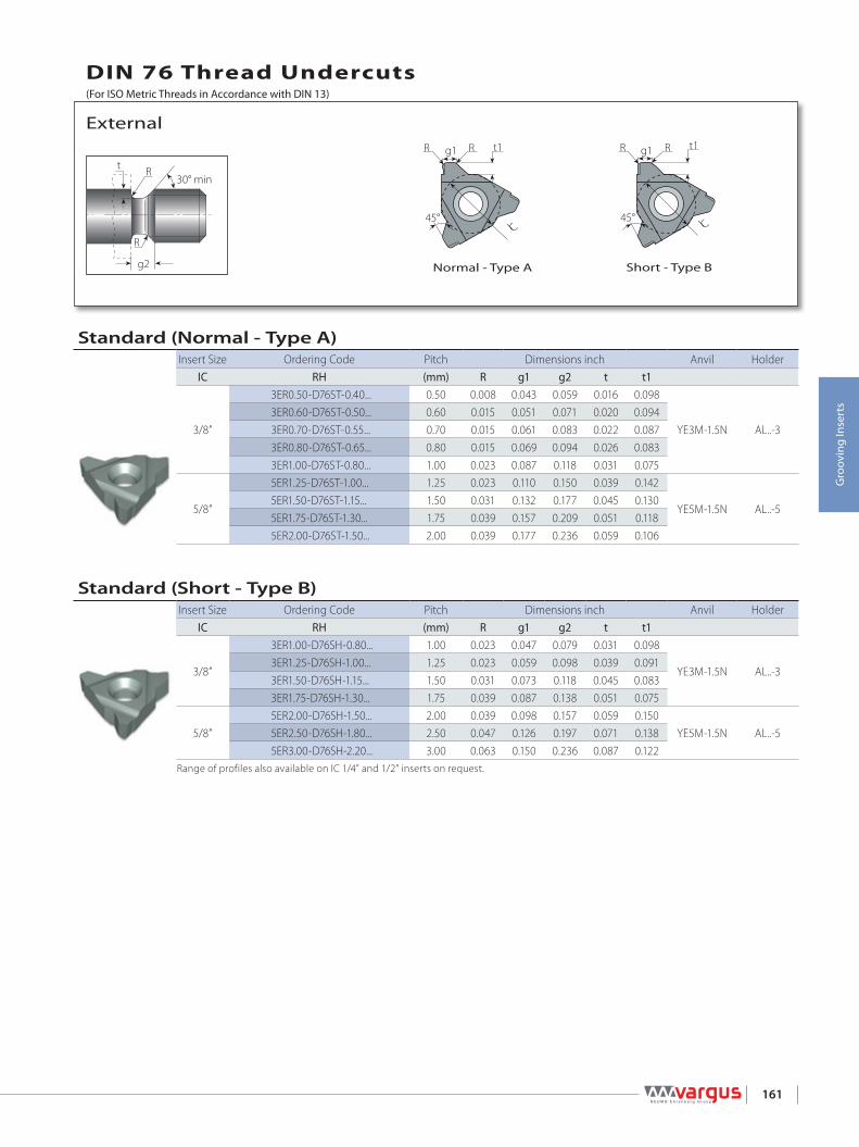
161
Gro
ovin
g In
sert
s
Standard (Normal - Type A)Insert Size Ordering Code Pitch Dimensions inch Anvil Holder
IC RH (mm) R g1 g2 t t1
3/8”
3ER0.50-D76ST-0.40... 0.50 0.008 0.043 0.059 0.016 0.098
YE3M-1.5N AL..-33ER0.60-D76ST-0.50... 0.60 0.015 0.051 0.071 0.020 0.0943ER0.70-D76ST-0.55... 0.70 0.015 0.061 0.083 0.022 0.0873ER0.80-D76ST-0.65... 0.80 0.015 0.069 0.094 0.026 0.0833ER1.00-D76ST-0.80... 1.00 0.023 0.087 0.118 0.031 0.075
5/8”
5ER1.25-D76ST-1.00... 1.25 0.023 0.110 0.150 0.039 0.142
YE5M-1.5N AL..-55ER1.50-D76ST-1.15... 1.50 0.031 0.132 0.177 0.045 0.1305ER1.75-D76ST-1.30... 1.75 0.039 0.157 0.209 0.051 0.1185ER2.00-D76ST-1.50... 2.00 0.039 0.177 0.236 0.059 0.106
Standard (Short - Type B)Insert Size Ordering Code Pitch Dimensions inch Anvil Holder
IC RH (mm) R g1 g2 t t1
3/8”
3ER1.00-D76SH-0.80... 1.00 0.023 0.047 0.079 0.031 0.098
YE3M-1.5N AL..-33ER1.25-D76SH-1.00... 1.25 0.023 0.059 0.098 0.039 0.0913ER1.50-D76SH-1.15... 1.50 0.031 0.073 0.118 0.045 0.0833ER1.75-D76SH-1.30... 1.75 0.039 0.087 0.138 0.051 0.075
5/8”5ER2.00-D76SH-1.50... 2.00 0.039 0.098 0.157 0.059 0.150
YE5M-1.5N AL..-55ER2.50-D76SH-1.80... 2.50 0.047 0.126 0.197 0.071 0.1385ER3.00-D76SH-2.20... 3.00 0.063 0.150 0.236 0.087 0.122
Range of profiles also available on IC 1/4” and 1/2” inserts on request.
30° min
R
R
g2
t
IC
g1 R t1R
45° 45° IC
g1 R t1R
DIN 76 Thread Undercuts
External
Normal - Type A Short - Type B
(For ISO Metric Threads in Accordance with DIN 13)

162
Gro
ovin
g In
sert
s
Standard (Normal - Type C)Insert Size Ordering Code Pitch Dimensions inch Anvil Holder
IC RH (mm) R g1 g2 t t1
3/8”
3IR0.50-D76ST-0.40... 0.50 0.008 0.043 0.059 0.016 0.098
Y13M-1.5N AL..-33IR0.60-D76ST-0.50... 0.60 0.015 0.051 0.071 0.020 0.0943IR0.70-D76ST-0.55... 0.70 0.015 0.061 0.083 0.022 0.0873IR0.80-D76ST-0.65... 0.80 0.015 0.069 0.094 0.026 0.0833IR1.00-D76ST-0.80... 1.00 0.023 0.087 0.118 0.031 0.075
Range of profiles also available on IC 1/4”, 1/2” and 5/8” inserts on request.For minimum bore diameters, refer to page 167.
Standard (Short - Type D)Insert Size Ordering Code Pitch Dimensions inch Anvil Holder
IC RH (mm) R g1 g2 t t1
3/8”
3IR1.00-D76SH-0.80... 1.00 0.023 0.047 0.079 0.031 0.098
Y13M-1.5N AL..-33IR1.25-D76SH-1.00... 1.25 0.023 0.059 0.098 0.039 0.0913IR1.50-D76SH-1.15... 1.50 0.031 0.073 0.118 0.045 0.0833IR1.75-D76SH-1.30... 1.75 0.039 0.087 0.138 0.051 0.075
Range of profiles also available on IC 1/4”, 1/2” and 5/8” inserts on request.For minimum bore diameters, refer to page 167.
Micro - Double EndedInsert dia. Ordering Code Groove Std. Dimensions inch Min. Bore dia.
Holderd (mm) RH m (H13) W L1 L B t F inch
6.0
6.0SIR1.6S-D3770S-1.5... 0.063 0.078 0.36 1.420.071 0.059 0.114
0.24 SMC..-6.0
6.0SIR1.6M-D3770S-1.5... 0.063 0.078 0.64 1.976.0SIR1.6L-D3770S-1.5... 0.063 0.078 0.84 2.366.0SIR2.0S-D3770D-1.8... 0.079 0.094 0.36 1.42
0.079 0.071 0.1146.0SIR2.0M-D3770D-1.8... 0.079 0.094 0.64 1.976.0SIR2.0L-D3770D-1.8... 0.079 0.094 0.84 2.36
g2g1
30° min
t
R
R
45°
t1
IC
g1R R
45°IC
g1R
t1
R
m
L
tBF
W
L1d
DIN 76 Thread Undercuts(For ISO Metric Threads in Accordance with DIN 13)
Internal
Normal - Type C Short - TypeD
DIN 3770 - GroovesInternal
RH-Double Ended

163
Gro
ovin
g In
sert
s
Snap Ring Grooves Inch Standard
Internal
Micro (Partial Profile)Insert Dia. Groove Std. Dimensions mm Min. Bore
dia.d mm RH-Double Ended R W L1 L B t F Holder
3.0 3.0SIR.015S-SNAP-.02... 0.015 0.03 0.354 1.42 0.035 0.024 0.055 SMC0...-3.0 0.1263.0SIR.015M-SNAP-.02... 0.015 0.03 0.63 1.97
4.0
4.0SIR.015S-SNAP-.02... 0.015 0.03 0.354 1.420.035 0.024
0.075 SMC0...-4.0 0.161
4.0SIR.015M-SNAP-.02... 0.015 0.03 0.63 1.974.0SIR.015L-SNAP-.02... 0.015 0.03 0.827 2.364.0SIR.023S-SNAP-.03... 0.023 0.047 0.354 1.42
0.047 0.0354.0SIR.023M-SNAP-.03... 0.023 0.047 0.63 1.974.0SIR.023L-SNAP-.03... 0.023 0.047 0.827 2.364.0SIR.031S-SNAP-.05... 0.031 0.062 0.354 1.42
0.059 0.0474.0SIR.031M-SNAP-.05... 0.031 0.062 0.63 1.974.0SIR.031L-SNAP-.05... 0.031 0.062 0.827 2.36
6.0
6.0SIR.031S-SNAP-.05... 0.031 0.062 0.354 1.42
0.063 0.051
0.114 SMC0...-6.0 0.24
6.0SIR.031M-SNAP-.05... 0.031 0.062 0.63 1.976.0SIR.031L-SNAP-.05... 0.031 0.062 0.827 2.366.0SIR.036S-SNAP-.05... 0.036 0.072 0.354 1.426.0SIR.036M-SNAP-.05... 0.036 0.072 0.63 1.976.0SIR.036L-SNAP-.05... 0.036 0.072 0.827 2.366.0SIR.039S-SNAP-.05... 0.039 0.078 0.354 1.426.0SIR.039M-SNAP-.05... 0.039 0.078 0.63 1.976.0SIR.039L-SNAP-.05... 0.039 0.078 0.827 2.366.0SIR.047S-SNAP-.05... 0.047 0.094 0.354 1.426.0SIR.047M-SNAP-.05... 0.047 0.094 0.63 1.976.0SIR.047L-SNAP-.05... 0.047 0.094 0.827 2.366.0SIR.062S-SNAP-.07... 0.062 0.125 0.354 1.42
0.079 0.0676.0SIR.062M-SNAP-.07... 0.062 0.125 0.63 1.976.0SIR.062L-SNAP-.07... 0.062 0.125 0.827 2.36
R
L
tBF
WL1
R
d
RH-Double Ended
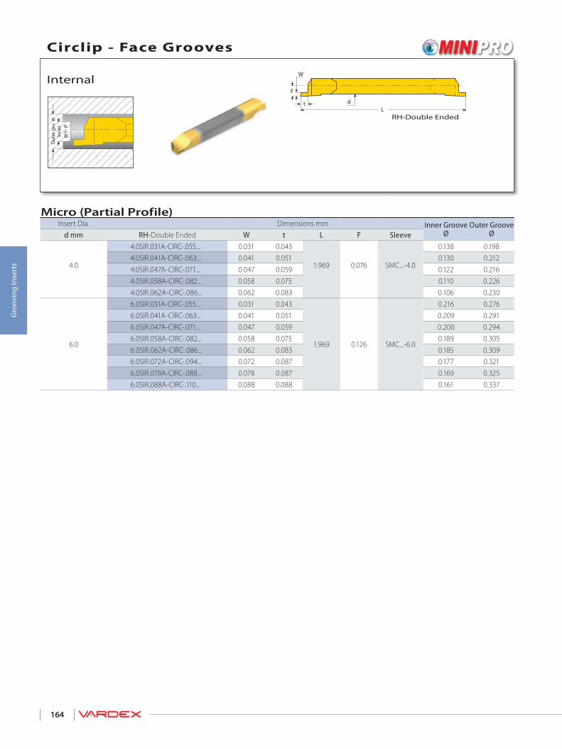
164
Gro
ovin
g In
sert
s
Circlip - Face Grooves
Internal
Micro (Partial Profile)Insert Dia. Dimensions mm Inner Groove
ØOuter Groove
Ød mm RH-Double Ended W t L F Sleeve
4.0
4.0SIR.031A-CIRC-.055... 0.031 0.043
1.969 0.076 SMC...-4.0
0.138 0.1984.0SIR.041A-CIRC-.063... 0.041 0.051 0.130 0.2124.0SIR.047A-CIRC-.071... 0.047 0.059 0.122 0.2164.0SIR.058A-CIRC-.082... 0.058 0.075 0.110 0.2264.0SIR.062A-CIRC-.086... 0.062 0.083 0.106 0.230
6.0
6.0SIR.031A-CIRC-.055... 0.031 0.043
1.969 0.126 SMC...-6.0
0.216 0.2766.0SIR.041A-CIRC-.063... 0.041 0.051 0.209 0.2916.0SIR.047A-CIRC-.071... 0.047 0.059 0.200 0.2946.0SIR.058A-CIRC-.082... 0.058 0.075 0.189 0.3056.0SIR.062A-CIRC-.086... 0.062 0.083 0.185 0.3096.0SIR.072A-CIRC-.094... 0.072 0.087 0.177 0.3216.0SIR.078A-CIRC-.088... 0.078 0.087 0.169 0.3256.0SIR.088A-CIRC-.110... 0.088 0.088 0.161 0.337
L
F
W
t
Inne
rgr
v. Ø
Out
er g
rv. Ø
d
RH-Double Ended

> Toolholders
Grooving

166
Gro
ovin
g To
olho
lder
s
Standard Spare Parts
Insert Size Ordering Code EDP No. Dimensions inch
IC RH H=H1=B F L1 L2 Insert Screw Anvil Screw Torx Key Anvil RH1/4” NL031-2 66214 0.31 0.43 5.37 0.69 SN2T - K2T -
3/8”
AL3/8-3 66091 0.37 0.63 2.45 0.76
SA3T SY3T K3T YE3M-1.5N
AL050-3 66000 0.50 0.63 3.27 0.87AL0625-3 66005 0.63 0.63 5.00 1.02AL075-3 66007 0.75 0.75 5.00 1.02AL100-3 66016 1.00 1.00 6.00 1.20AL125-3 66036 1.25 1.25 7.00 1.18
1/2”AL100-4 66024 1.00 1.00 6.00 1.42
SA4T SY4T K4T YE4M-1.5NAL125-4 66042 1.25 1.25 7.00 1.42AL150-4 66066 1.50 1.50 8.00 1.42
5/8”
AL100-5 66034 1.00 1.25 6.00 1.57
SA5T SY5T K5T YE5M-1.5NAL125-5 66051 1.25 1.25 7.00 1.57AL150-5 66073 1.50 1.50 8.00 1.57AL200-5 66085 2.00 2.00 10.00 1.57
* The toolholders are supplied with standard anvils. For Grooving, please use the anvils indicated in the table above.
BF
L2L1
HH1
*
External Toolholders
External Standard ..............................................................................................................................................................................Page 166
Internal Standard ...............................................................................................................................................................................Page 167
Internal Mini-L .....................................................................................................................................................................................Page 168
Internal Mini-L - Adjustable ........................................................................................................................................................Page 168
Micro .........................................................................................................................................................................................................Page 169
GROOVING TOOLHOLDERS
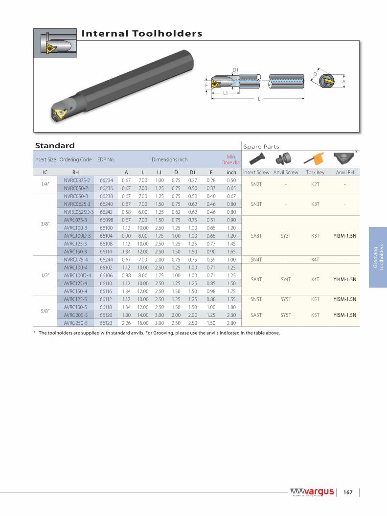
167
Gro
ovin
g To
olho
lder
s
Standard Spare Parts
Insert Size Ordering Code EDP No. Dimensions inch Min. Bore dia.
IC RH A L L1 D D1 F inch Insert Screw Anvil Screw Torx Key Anvil RH
1/4”NVRC0375-2 66234 0.67 7.00 1.00 0.75 0.37 0.28 0.50
SN2T - K2T -NVRC050-2 66236 0.67 7.00 1.25 0.75 0.50 0.37 0.65
3/8”
NVRC050-3 66238 0.67 7.00 1.25 0.75 0.50 0.40 0.67SN3T - K3T -NVRC0625-3 66240 0.67 7.00 1.50 0.75 0.62 0.46 0.80
NVRC0625D-3 66242 0.58 6.00 1.25 0.62 0.62 0.46 0.80AVRC075-3 66098 0.67 7.00 1.50 0.75 0.75 0.51 0.90
SA3T SY3T K3T YI3M-1.5NAVRC100-3 66100 1.12 10.00 2.50 1.25 1.00 0.65 1.20AVRC100D-3 66104 0.90 8.00 1.75 1.00 1.00 0.65 1.20AVRC125-3 66108 1.12 10.00 2.50 1.25 1.25 0.77 1.45AVRC150-3 66114 1.34 12.00 2.50 1.50 1.50 0.90 1.65
1/2”
NVRC075-4 66244 0.67 7.00 2.00 0.75 0.75 0.59 1.00 SN4T - K4T -AVRC100-4 66102 1.12 10.00 2.50 1.25 1.00 0.71 1.25
SA4T SY4T K4T YI4M-1.5NAVRC100D-4 66106 0.88 8.00 1.75 1.00 1.00 0.71 1.25AVRC125-4 66110 1.12 10.00 2.50 1.25 1.25 0.85 1.50AVRC150-4 66116 1.34 12.00 2.50 1.50 1.50 0.98 1.75
5/8”
AVRC125-5 66112 1.12 10.00 2.50 1.25 1.25 0.88 1.55 SN5T SY5T K5T YI5M-1.5NAVRC150-5 66118 1.34 12.00 2.50 1.50 1.50 1.00 1.80
SA5T SY5T K5T YI5M-1.5NAVRC200-5 66120 1.80 14.00 3.00 2.00 2.00 1.25 2.30AVRC250-5 66123 2.26 16.00 3.00 2.50 2.50 1.50 2.80
* The toolholders are supplied with standard anvils. For Grooving, please use the anvils indicated in the table above.
AD
F
LL1
D1
*
Internal Toolholders

168
Gro
ovin
g To
olho
lder
s
Mini-L Spare Parts
Insert Size Ordering Code EDP No. Dimensions inch Anti-Vibration System
IC RH A L L1 D D1 Insert Screw Torx Key
5.0L
SNVR 0375U-5L 67336 0.36 3.19 0.63 0.37 0.24 No
SN5LT K5LT
BNVR 0375S-5L 67306 0.36 3.43 0.87 0.37 0.24 Carbide ImplantedBNVR 0375M-5L 67302 0.36 3.82 1.22 0.37 0.24 Carbide ImplantedBNVR 0375L-5L 67300 0.36 4.29 1.69 0.37 0.24 Carbide Implanted
5.0L
SNVR 050U-5L 67340 0.49 3.19 0.63 0.50 0.24 NoBNVR 050S-5L 67315 0.49 3.43 0.87 0.50 0.24 Carbide ImplantedBNVR 050M-5L 67311 0.49 3.82 1.22 0.50 0.24 Carbide ImplantedBNVR 050L-5L 67309 0.49 4.29 1.69 0.50 0.24 Carbide Implanted
Mini-L - Adjustable Spare Parts
Insert Size Ordering Code
EDP No.
EDP No. Dimensions inch
IC Sleeve Holder RH A L L1 D D1 Insert Screw Torx Key for Insert Screw Holder Screw x 3 Key for Holder Screw5.0L SV0625-6.2 67343 BNVR6.2T-5L 67324 .584 4 0.315-1.73 .625 .244 SN5LT K5LT S4.0 K2.0
D
L1
D1
A
L
D
L1
D1
A
L
Internal Toolholders

169
Gro
ovin
g To
olho
lder
s
Spare Parts
Micro - Double Ended
MicroInsert Dia.
Shank Dia. Ordering Code EDP No. Dimensions inch Location Screw* Clamping Screw x 3
d [mm] D L L1 L0 Screw M Key Screw Key
30.50 SMC050-3.0 41075 3.15
0.35- Short 3.50 4GISM8X28 1.10
K4.0 M4X0.7X4.0 K2.0
0.63- Medium 3.78 4GISM8X21 0.830.63 SMC0625-3.0 40210
3.740.35- Short 4.09 4GISM8X49 1.93
0.75 SMC075-3.0 41080 0.63- Medium 4.37 4GISM8X42 1.65
4
0.50 SMC050-4.0 41092 3.15
0.35- Short 3.50 4GISM8X28 1.10
0.63- Medium 3.78 4GISM8X21 0.83
0.83- Long 3.98 4GISM8X16 0.63
0.63 SMC0625-4.0 402123.74
0.35- Short 4.09 4GISM8X49 1.93
0.63- Medium 4.37 4GISM8X42 1.650.75 SMC075-4.0 41081 0.83- Long 4.57 4GISM8X37 1.46
6
0.50 SMC050-6.0 41517 3.150.35- Short 3.5 4GISM8X28 1.100.63- Medium 3.78 4GISM8X21 0.830.83- Long 3.98 4GISM8X16 0.63
0.63 SMC0625-6.0 402143.74
0.35- Short 4.09 4GISM8X49 1.930.63- Medium 4.37 4GISM8X42 1.65
0.75 SMC075-6.0 41082 0.83- Long 4.57 4GISM8X37 1.46* Every toolholder package contains the full range of location screws needed.
L
L1
d
L0D
Internal Toolholders
Location Screw
Double Ended
M

170
Gro
ovin
g To
olho
lder
s
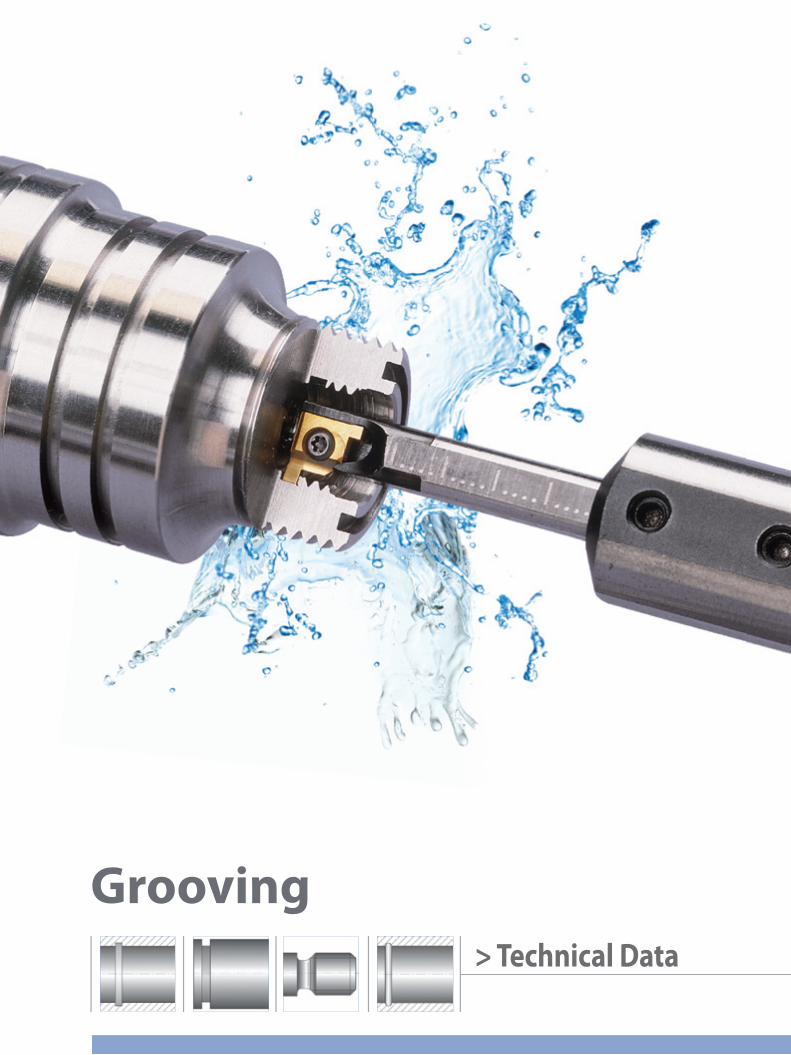
> Technical Data
Grooving
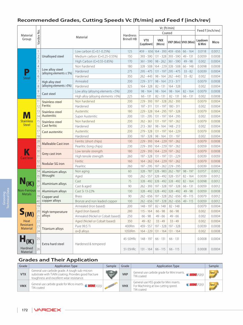
172
Gro
ovin
g Te
chni
cal D
ata
Material Group
Vard
ex N
o.Material Hardness
Brinell HB
Vc [ft/min]Feed f [inch/rev]
Coated
VTX (Laydown)
VMX (Micro) VKP (Mini) VHX (Mini) Laydown
& Mini Micro
PSteel
1Unalloyed steel
Low carbon (C=0.1-0.25%) 125 459 - 656 164 - 393 459 - 656 66 - 164 0.0118 0.00122 Medium carbon (C=0.25-0.55%) 150 393 - 590 131 - 328 393 - 590 49 - 131 0.0059 0.00083 High Carbon (C=0.55-0.85%) 170 361 - 590 98 - 262 361 - 590 49 - 98 0.002 0.00044
Low alloy steel(alloying elements ≤ 5%)
Non hardened 180 328 - 508 164 - 229 328 - 508 66 - 148 0.0098 0.00085 Hardened 275 295 - 475 131 - 197 295 - 475 33 - 82 0.0039 0.00046 Hardened 350 262 - 443 98 - 164 262 - 443 33 - 82 0.002 0.00047 High alloy steel
(alloying elements >5%) Annealed 200 229 - 377 98 - 164 213 - 377 0.0079 0.0008
8 Hardened 325 164 - 328 82 - 131 164 - 328 0.002 0.00049
Cast steel Low alloy (alloying elements <5%) 200 98 - 164 98 - 164 98 - 164 82 - 164 0.0079 0.0008
10 High alloy (alloying elements >5%) 225 66 - 131 82 - 131 82 - 131 66 - 131 0.002 0.0008
MStainless
Steel
11 Stainless steelFeritic
Non hardened 200 229 - 393 197 - 328 262 - 393 0.0079 0.000412 Hardened 330 197 - 311 131 - 197 180 - 311 0.002 0.000413 Stainless steel
Austenitic Austenitic 180 229 - 328 164 - 295 197 - 328 0.0079 0.0004
14 Super Austenitic 200 131 - 295 131 - 197 164 - 295 0.002 0.000415 Stainless steel
Cast feritic Non hardened 200 262 - 361 131 - 197 197 - 262 0.0079 0.0008
16 Hardened 330 213 - 361 98 - 164 148 - 213 0.002 0.000417 Cast austenitic
Austenitic 200 279 - 328 131 - 197 164 - 229 0.0079 0.0008
18 Hardened 330 197 - 328 98 - 164 131 - 197 0.002 0.0004
KCast Iron
28Malleable Cast iron
Ferritic (short chips) 130 229 - 393 164 - 229 197 - 262 0.0079 0.000829 Pearlitic (long chips) 230 229 - 393 164 - 229 197 - 262 0.0059 0.000430
Grey cast iron Low tensile strength 180 229 - 393 164 - 229 197 - 262 0.0079 0.0008
31 High tensile strength 260 197 - 328 131 - 197 131 - 229 0.0039 0.005932
Nodular SG iron Feritic 160 164 - 262 164 - 229 197 - 262 0.0079 0.0008
33 Pearlitic 260 197 - 295 197 - 262 229 - 295 0.0039 0.0004
N(K)Non-Ferrous
Metals
34 Aluminium alloys Wrought
Non aging 60 328 - 787 328 - 983 262 - 787 98 - 197 0.0157 0.001235 Aged 100 262 - 557 328 - 492 328 - 557 82 - 164 0.0039 0.001236
Aluminium alloys Cast 75 328 - 492 328 - 492 328 - 492 82 - 164 0.0098 0.0012
37 Cast & aged 90 262 - 393 197 - 328 197 - 328 66 - 131 0.0059 0.001238 Aluminium alloys Cast Si 13-22% 130 328 - 492 328 - 492 328 - 492 49 - 98 0.0059 0.000839 Copper and
copper alloys Brass 90 262 - 656 197 - 328 262 - 656 49 - 115 0.0079 0.0012
40 Bronze and non leaded copper 100 262 - 656 197 - 328 262 - 656 49 - 115 0.0059 0.0012
S(M)Heat
ResistantMaterial
19
High temperaturealloys
Annealed (Iron based) 200 148 - 197 82 - 148 82 - 148 0.0079 0.000420 Aged (Iron based) 280 115 - 164 66 - 98 66 - 98 0.002 0.000421 Annealed (Nickel or Cobalt based) 250 66 - 98 49 - 66 49 - 66 0.002 0.000422 Aged (Nickel or Cobalt based) 350 49 - 82 33 - 49 33 - 49 0.002 0.000423
Titanium alloys Pure 99.5 Ti 400Rm 459 - 557 197 - 328 197 - 328 0.0039 0.0008
24 α+β alloys 1050Rm 164 - 229 131 - 164 131 - 164 0.002 0.0008
H(K)Hardned Material
25
Extra hard steel Hardened & tempered
45-50HRc 148 - 197 66 - 131 66 - 131 0.0008 0.0004
26 51-55HRc 131 - 164 66 - 115 66 - 115 0.0008 0.0004
Grades and Their ApplicationGrade Application Type Sample Grade Application Type Sample
VTXGeneral use carbide grade. A tough sub-micron substrate with TiAlN coating. Provides good fracture toughness and excellent wear resistance.
VKP General use carbide grade for Mini inserts. TiN coated
VMX General use carbide grade for Micro inserts. TiN coated VHX
General use HSS grade for Mini inserts. For Machining at low cutting speed. TiN coated
Recommended Grades, Cutting Speeds Vc [ft/min] and Feed f [inch/rev]

> Inserts
Boring

174
Borin
g In
sert
s
VARDEX Ordering Code System ...............................................................................................................................................Page 175
CD0W Inserts .......................................................................................................................................................................................Page 176
TD0W Inserts ........................................................................................................................................................................................Page 176
WC0W Inserts ......................................................................................................................................................................................Page 177
Boring - Micro ......................................................................................................................................................................................Page 178
Copy - Micro .........................................................................................................................................................................................Page 179
Chamfer - Micro .................................................................................................................................................................................Page 179
Long Nose - Micro ............................................................................................................................................................................Page 180
Back Edge - Micro .............................................................................................................................................................................Page 181
Boredrill - Micro ..................................................................................................................................................................................Page 181
BORING INSERTS

175
Borin
g In
sert
s
T1
D2
03
W4
415
146
VTX7
1- Insert Shape
C - Diamond 80 deg.T - TriangleW - Trigon 80 deg.
5 - Insert Dimension
40-IC 0.156” - Thickness-0.040"41-IC 0.160” - Thickness-0.047"42-IC 0.156” - Thickness-0.062"50-IC 0.187” - Thickness-0.094"
2 - Clearance Angle
C - 7 deg.D - 15 deg.
6 - Corner Radius
11- R 0.0212- R 0.00713- R 0.00814- R 0.015
3 - Tolerance Class0 - Special Tolerance Class
7 - Carbide GradeVTX
4 - Insert TypeW - Hole + Countersink
6.01
S2
I3
R4
0.25
M6
- Bore7
- 18
VMX9
1- Insert Dia. (mm)
3.04.06.0 8.010.0
2 - Tool GroupS - Solid Carbide
6 - Tool Length
U - Ultra ShortS - ShortM - MediumL - Long
3 - Type of InsertI - Internal
4 - RH or LH
R - Right Hand InsertL - Left Hand Insert
5 - Corner Radius (mm)0.2
7 - Tool Application
Bore - BoringCopy - Boring CopyChamfer - Boring ChamferBack - Back Edge3527, 3537, 3547 - Long NoseBD - Bore Drill
8 - Front Relief
1 - With Relief0 - Without Relief
9 - Carbide GradeVMX
Vardex Ordering Code SystemPowerBore Inserts
Micro Boring Inserts - Double Ended
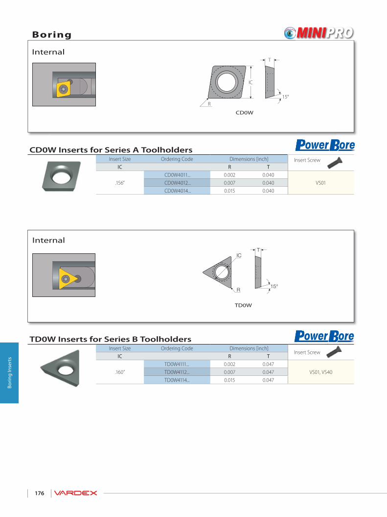
176
Borin
g In
sert
s
CD0W Inserts for Series A ToolholdersInsert Size Ordering Code Dimensions [inch] Insert Screw
IC R T
.156”CD0W4011... 0.002 0.040
VS01CD0W4012... 0.007 0.040CD0W4014... 0.015 0.040
TD0W Inserts for Series B ToolholdersInsert Size Ordering Code Dimensions [inch]
Insert ScrewIC R T
.160”TD0W4111... 0.002 0.047
VS01, VS40TD0W4112... 0.007 0.047TD0W4114... 0.015 0.047
R
IC
T
15°
R15°
ICT
Boring
Internal
CD0W
Internal
TD0W
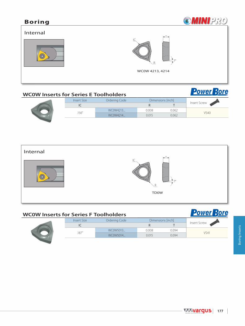
177
Borin
g In
sert
s
WC0W Inserts for Series E ToolholdersInsert Size Ordering Code Dimensions [inch]
Insert ScrewIC R T
.156”WC0W4213... 0.008 0.062
VS40WC0W4214... 0.015 0.062
WC0W Inserts for Series F ToolholdersInsert Size Ordering Code Dimensions [inch]
Insert ScrewIC R T
.187”WC0W5013... 0.008 0.094
VS41WC0W5014... 0.015 0.094
7°R
ICT
R7°
ICT
Boring
Internal
WC0W 4213, 4214
Internal
TD0W
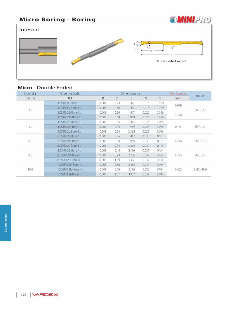
178
Borin
g In
sert
s
Micro - Double EndedInsert dia. Ordering Code Dimensions inch Min. Bore dia.
Holderd (mm) RH R L1 L S F inch
3.0
3.0SIR0.1U-Bore-1... 0.004 0.23 1.417 0.016 0.0090.079
SMC..-3.03.0SIR0.1S-Bore-1... 0.004 0.36 1.417 0.016 0.0093.0SIR0.2S-Bore-1... 0.008 0.36 1.417 0.026 0.056
0.1263.0SIR0.2M-Bore-1... 0.008 0.64 1.969 0.026 0.056
4.04.0SIR0.2S-Bore-1... 0.008 0.36 1.417 0.026 0.076
0.165 SMC..-4.04.0SIR0.2M-Bore-1... 0.008 0.64 1.969 0.026 0.0764.0SIR0.2L-Bore-1... 0.008 0.84 2.362 0.026 0.076
6.06.0SIR0.2S-Bore-1... 0.008 0.36 1.417 0.030 0.115
0.244 SMC..-6.06.0SIR0.2M-Bore-1... 0.008 0.64 1.969 0.030 0.1156.0SIR0.2L-Bore-1... 0.008 0.84 2.362 0.030 0.115
8.08.0SIR0.2S-Bore-1... 0.008 0.48 2.126 0.032 0.154
0.323 SMC..-8.08.0SIR0.2M-Bore-1... 0.008 0.79 2.756 0.032 0.1548.0SIR0.2L -Bore-1... 0.008 1.09 3.386 0.032 0.154
10.010.0SIR0.2S-Bore-1... 0.008 0.58 2.362 0.039 0.194
0.402 SMC..-10.010.0SIR0.2M-Bore-1... 0.008 0.99 3.150 0.039 0.19410.0SIR0.2L-Bore-1... 0.008 1.37 3.937 0.039 0.194
dL1
L
FSR
Micro Boring - Boring
Internal
RH-Double Ended

179
Borin
g In
sert
s
Micro - Double EndedInsert dia. Ordering Code Dimensions inch Min. Bore dia.
Holderd (mm) RH R L1 L F S1 S inch
4.04.0SIR0.2S-Chamfer-0... 0.008 0.36 1.417 0.076 0.031 0.016
0.165 SMC...-4.04.0SIR0.2M-Chamfer-0... 0.008 0.64 1.969 0.076 0.031 0.0164.0SIR0.2L-Chamfer-0... 0.008 0.84 2.362 0.076 0.031 0.016
6.06.0SIR0.2S-Chamfer-0... 0.008 0.36 1.417 0.115 0.039 0.028
0.244 SMC...-6.06.0SIR0.2M-Chamfer-0... 0.008 0.64 1.969 0.115 0.039 0.0286.0SIR0.2L-Chamfer-0... 0.008 0.84 2.362 0.115 0.039 0.028
Micro - Double EndedInsert dia. Ordering Code Dimensions inch Min. Bore dia.
Holderd (mm) RH R L1 L S F inch
4.04.0SIR0.2S-Copy-1... 0.008 0.36 1.417 0.039 0.076
0.165 SMC..-4.04.0SIR0.2M-Copy-1... 0.008 0.64 1.969 0.039 0.0764.0SIR0.2L-Copy-1... 0.008 0.84 2.362 0.039 0.076
6.06.0SIR0.2S-Copy-1... 0.008 0.36 1.417 0.051 0.115
0.276 SMC..-6.06.0SIR0.2M-Copy-1... 0.008 0.64 1.969 0.051 0.1156.0SIR0.2L-Copy-1... 0.008 0.84 2.362 0.051 0.115
dL1
L
FSR25°
d
L
F90°
L1
RS1
SRS1
S
F
Micro Boring Copy
Internal
RH-Double Ended
Micro Boring Chamfer
Internal
RH-Double Ended

180
Borin
g In
sert
s
Micro - Double EndedInsert dia. Ordering Code Dimensions inch Min. Bore dia.
Holderd(mm) RH R L1 L F S inch
6.06.0SIR0.2S-3527-1... 0.008 0.36 1.417 0.106 0.115
0.272 SMC...-6.06.0SIR0.2M-3527-1... 0.008 0.64 1.969 0.106 0.1156.0SIR0.2L-3527-1... 0.008 0.84 2.362 0.106 0.115
8.08.0SIR0.2S-3537-1... 0.008 0.48 2.126 0.146 0.154
0.35 SMC...-8.08.0SIR0.2M-3537-1... 0.008 0.79 2.756 0.146 0.1548.0SIR0.2L-3537-1... 0.008 1.09 3.386 0.146 0.154
10.010.0SIR0.2S-3547-1... 0.008 0.58 2.362 0.185 0.194
0.425 SMC...-10.010.0SIR0.2M-3547-1... 0.008 0.99 3.150 0.185 0.19410.0SIR0.2L-3547-1... 0.008 1.37 3.937 0.185 0.194
L1d
L
FS
35°
RR
Micro Boring - Long Nose
Internal
RH-Double Ended

181
Borin
g In
sert
s
Micro - Double EndedInsert dia. Ordering Code Dimensions inch Min. Bore dia.
Holderd(mm) RH R L1 L A W W1 S S1 F inch
3.03.0SIR0.2S-Back-1... 0.002 0.36 1.417
0.135 0.059 0.071 0.031 0.024 0.056 0.126 SMC...-3.03.0SIR0.2M-Back-1... 0.002 0.64 1.969
4.04.0SIR0.2S-Back-1... 0.002 0.36 1.417
0.175 0.079 0.092 0.051 0.039 0.076 0.165 SMC...-4.04.0SIR0.2M-Back-1... 0.002 0.64 1.9694.0SIR0.2L-Back-1... 0.002 0.84 2.362
6.06.0SIR0.2S-Back-1... 0.002 0.36 1.417
0.254 0.079 0.097 0.075 0.063 0.115 0.244 SMC...-6.06.0SIR0.2M-Back-1... 0.002 0.64 1.9696.0SIR0.2L-Back-1... 0.002 0.84 2.362
Micro - Double EndedInsert dia. Ordering Code Dimensions inch Min. Bore dia.
Holderd(mm) RH L1 L A inch
4.0 4.0SIR0.2M-BD-1... 0.64 1.969 0.139 0.147 SMC...-4.0
6.06.0SIR0.2M-BD-1... 0.64 1.969
0.205 0.228 SMC...-6.06.0SIR0.2L-BD-1... 0.84 2.362
8.08.0SIR0.2S-BD-1... 0.48 2.126
0.272 0.307 SMC...-8.08.0SIR0.2M-BD-1... 0.79 2.7568.0SIR0.2L-BD-1... 1.09 3.386
A
W1
L
dSF
W L1S1
7º
R
A
L1 d
L D
R0.2
D H
ole
7º
Micro Boring - Back Edge
Internal
RH-Double Endedmin. width
Micro Boring - Boredrill
Internal
RH-Double Ended
(mm)

182
Borin
g In
sert
s

> Toolholders
Boring

184
Borin
g H
olde
rs
C1
062
- 233
C4
405
56
1- Shank Style
C - CarbideS - Steel
2 - Shank Dia. 05 - 5/32" - 0.156 06 - 3/16" - 0.18708 - 1/4" - 0.25010 - 5/16" - 0.31212 - 3/8" - 0.37516 - 1/2" - 0.500
3 - Bar Dia. [D1]21 - 0.16523 - 0.18024 - 0.18726 - 0.20332 - 0.25040 - 0.312
4 - Insert Shape 5 - Holder Length [L2]23 - 2.2525 - 2.5027 - 2.7530 - 3.0035 - 3.5040 - 4.0045 - 4.5050 - 5.0060 - 6.00
S1
M2
C3
06254
- 35
1 - Holder Shape
S - Sleeve (Double Ended)
2 - Holder Type
M - Micro (Double Ended)
3 - CoolingC - Coolant Channel
4 - Holder Dia.
050 - 1/2"0625 - 5/8"075 - 3/4"
5 - Bore Size
Micro Size3, 4, 6, 8, 10
6 - Front Relief Angle0, 5, 7
C - Diamond 80 Deg.
T - Triangle
W- Trigon 80 Deg.
VARDEX Ordering Code System ...............................................................................................................................................Page 184
Series A - Boring Bars for CD0W Inserts ...............................................................................................................................Page 185
Series B - Boring Bars for TD0W Inserts ................................................................................................................................Page 186
Series E -Boring Bars for WC0W Inserts (4213, 4214) ...................................................................................................Page 187
Series F - Boring Bars for WC0W Inserts (5013, 5014) ..................................................................................................Page 188
Toolholders - Micro Double Ended ........................................................................................................................................Page 189
BORING TOOLHOLDERS
Vardex Ordering Code SystemPowerBore Toolholders
Micro
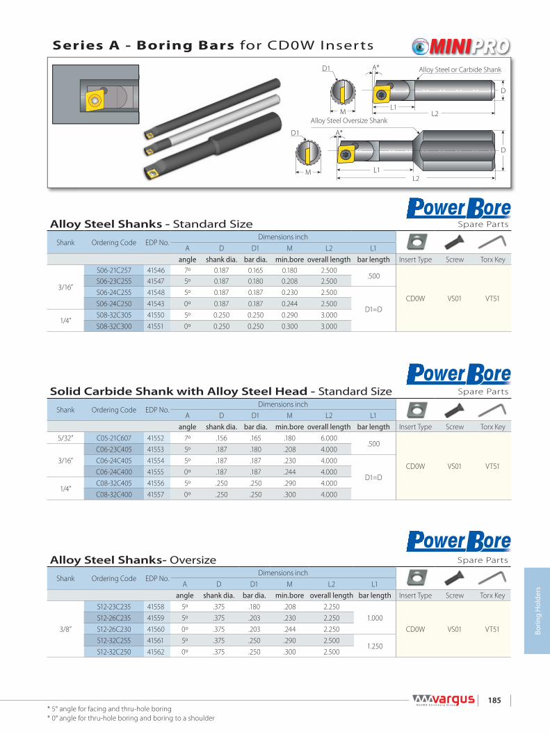
185
Borin
g H
olde
rs
Alloy Steel Shanks - Standard Size Spare Parts
Shank Ordering Code EDP No.Dimensions inch
A D D1 M L2 L1angle shank dia. bar dia. min.bore overall length bar length Insert Type Screw Torx Key
3/16”
S06-21C257 41546 7º 0.187 0.165 0.180 2.500.500
CD0W VS01 VT51
S06-23C255 41547 5º 0.187 0.180 0.208 2.500S06-24C255 41548 5º 0.187 0.187 0.230 2.500
D1=DS06-24C250 41543 0º 0.187 0.187 0.244 2.500
1/4”S08-32C305 41550 5º 0.250 0.250 0.290 3.000S08-32C300 41551 0º 0.250 0.250 0.300 3.000
Solid Carbide Shank with Alloy Steel Head - Standard Size Spare Parts
Shank Ordering Code EDP No.Dimensions inch
A D D1 M L2 L1angle shank dia. bar dia. min.bore overall length bar length Insert Type Screw Torx Key
5/32” C05-21C607 41552 7º .156 .165 .180 6.000.500
CD0W VS01 VT513/16”
C06-23C405 41553 5º .187 .180 .208 4.000C06-24C405 41554 5º .187 .187 .230 4.000
D1=DC06-24C400 41555 0º .187 .187 .244 4.000
1/4”C08-32C405 41556 5º .250 .250 .290 4.000C08-32C400 41557 0º .250 .250 .300 4.000
Alloy Steel Shanks- Oversize Spare Parts
Shank Ordering Code EDP No.Dimensions inch
A D D1 M L2 L1angle shank dia. bar dia. min.bore overall length bar length Insert Type Screw Torx Key
3/8”
S12-23C235 41558 5º .375 .180 .208 2.2501.000
CD0W VS01 VT51S12-26C235 41559 5º .375 .203 .230 2.250S12-26C230 41560 0º .375 .203 .244 2.250S12-32C255 41561 5º .375 .250 .290 2.500
1.250S12-32C250 41562 0º .375 .250 .300 2.500
D1
M
M
D1 A*
L2L1
D
A*
L2L1
D
Series A - Boring Bars for CD0W Inserts
Alloy Steel or Carbide Shank
Alloy Steel Oversize Shank
* 5° angle for facing and thru-hole boring* 0° angle for thru-hole boring and boring to a shoulder
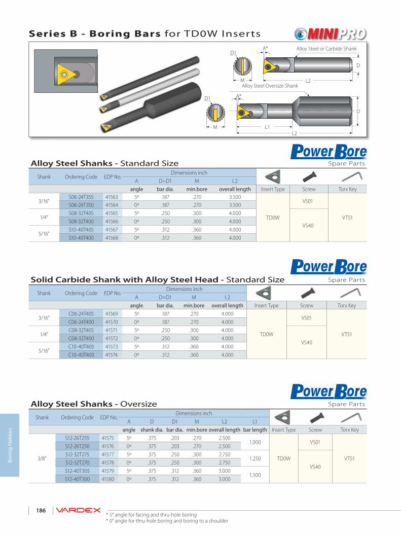
186
Borin
g H
olde
rs
M
D1 A*
L2L1
M
D1
D
A*
L2
D
Alloy Steel Shanks - Standard Size Spare Parts
Shank Ordering Code EDP No.Dimensions inch
A D=D1 M L2angle bar dia. min.bore overall length Insert Type Screw Torx Key
3/16”S06-24T355 41563 5º .187 .270 3.500
TD0W
VS01
VT51
S06-24T350 41564 0º .187 .270 3.500
1/4”S08-32T405 41565 5º .250 .300 4.000
VS40S08-32T400 41566 0º .250 .300 4.000
5/16”S10-40T405 41567 5º .312 .360 4.000S10-40T400 41568 0º .312 .360 4.000
Solid Carbide Shank with Alloy Steel Head - Standard Size Spare Parts
Shank Ordering Code EDP No.Dimensions inch
A D=D1 M L2angle bar dia. min.bore overall length Insert Type Screw Torx Key
3/16”C06-24T405 41569 5º .187 .270 4.000
TD0W
VS01
VT51
C06-24T400 41570 0º .187 .270 4.000
1/4”C08-32T405 41571 5º .250 .300 4.000
VS40C08-32T400 41572 0º .250 .300 4.000
5/16”C10-40T405 41573 5º .312 .360 4.000C10-40T400 41574 0º .312 .360 4.000
Alloy Steel Shanks - Oversize Spare Parts
Shank Ordering Code EDP No.Dimensions inch
A D D1 M L2 L1angle shank dia. bar dia. min.bore overall length bar length Insert Type Screw Torx Key
3/8”
S12-26T255 41575 5º .375 .203 .270 2.5001.000
TD0W
VS01
VT51
S12-26T250 41576 0º .375 .203 .270 2.500S12-32T275 41577 5º .375 .250 .300 2.750
1.250VS40
S12-32T270 41578 0º .375 .250 .300 2.750S12-40T305 41579 5º .375 .312 .360 3.000
1.500S12-40T300 41580 0º .375 .312 .360 3.000
Series B - Boring Bars for TD0W InsertsAlloy Steel or Carbide Shank
Alloy Steel Oversize Shank
* 5° angle for facing and thru-hole boring* 0° angle for thru-hole boring and boring to a shoulder
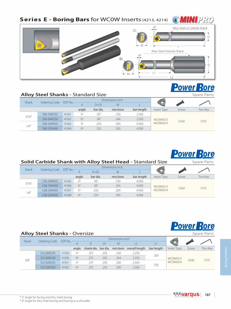
187
Borin
g H
olde
rs
Alloy Steel Shanks - Standard Size Spare Parts
Shank Ordering Code EDP No.Dimensions inch
A D=D1 M Langle bar dia. min.bore bar Iength Insert Type Screw Torx Key
3/16”S06-24W255 41581 5º .187 .230 2.500
WC0W4213WC0W4214 VS40 VT51
S06-24W250 41582 0º .187 .244 2.500
1/4”S08-32W405 41583 5º .250 .300 4.000S08-32W400 41584 0º .250 .300 4.000
M
D1
D
A*
L2L1
A*
L
D
M
D1
D1
Solid Carbide Shank with Alloy Steel Head - Standard Size Spare Parts
Shank Ordering Code EDP No.Dimensions inch
A D=D1 M Langle bar dia. min.bore bar Iength Insert Type Screw Torx Key
3/16”C06-24W405 41585 5º .187 .230 4.000
WC0W4213WC0W4214 VS40 VT51
C06-24W400 41586 0º .187 .244 4.000
1/4”C08-32W405 41587 5º .250 .290 4.000C08-32W400 41588 0º .250 .300 4.000
Alloy Steel Shanks - Oversize Spare Parts
Shank Ordering Code EDP No.Dimensions inch
A D D1 M L2 L1angle shank dia. bar dia. min.bore overall length bar length Insert Type Screw Torx Key
3/8”
S12-26W235 41589 5º .375 .203 .230 2.250.500
WC0W4213WC0W4214 VS40 VT51
S12-26W230 41590 0º .375 .203 .244 2.250S12-32W255 41591 5º .375 .250 .290 2.500
.750S12-32W250 41592 0º .375 .250 .300 2.500
Series E - Boring Bars for WC0W Inserts (4213, 4214)
Alloy Steel or Carbide Shank
Alloy Steel Oversize Shank
* 5° angle for facing and thru-hole boring* 0° angle for thru-hole boring and boring to a shoulder
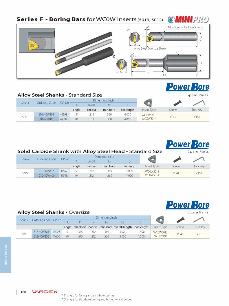
188
Borin
g H
olde
rs
A*
L
D
M
D
D1
M
A*
L2L1
D1
D1
Alloy Steel Shanks - Standard Size Spare Parts
Shank Ordering Code EDP No.Dimensions inch
A D=D1 M Langle bar dia. min.bore bar Iength Insert Type Screw Torx Key
5/16”S10-40W405 41593 5º .312 .360 4.000 WCOW5013
WCOW5014 VS41 VT51S10-40W400 41594 0º .312 .360 4.000
Solid Carbide Shank with Alloy Steel Head - Standard Size Spare Parts
Shank Ordering Code EDP No.Dimensions inch
A D=D1 M Langle bar dia. min.bore bar Iength Insert Type Screw Torx Key
5/16”C10-40W405 41597 5º .312 .360 4.000 WC0W5013
WC0W5014 VS41 VT51C10-40W400 41598 0º .312 .360 4.000
Alloy Steel Shanks - Oversize Spare Parts
Shank Ordering Code EDP No.Dimensions inch
A D D1 M L2 L1angle shank dia bar dia. min.bore overall length bar length Insert Type Screw Torx Key
3/8”S12-40W305 41599 5º .375 .312 .360 3.000 1.500 WC0W5013
WC0W5014 VS41 VT51S12-40W300 41600 0º .375 .312 .360 3.000 1.500
Series F - Boring Bars for WC0W Inserts (5013, 5014)
Alloy Steel or Carbide Shank
Alloy Steel Oversize Shank
* 5° angle for facing and thru-hole boring* 0° angle for thru-hole boring and boring to a shoulder

189
Borin
g H
olde
rs
L
L1
d
L0D
Internal Toolholders
Location Screw
Double Ended
M
Spare Parts
Micro - Double Ended
MicroInsert Dia.
Shank Dia. Ordering Code EDP No. Dimensions inch Location Screw* Clamping Screw x 3
d [mm] D L L1 L0 Screw M Key Screw Key
30.50 SMC050-3.0 41075 3.15
0.35- Short 3.50 4GISM8X28 1.10
K4.0
M4X0.7X4.0 K2.0
0.63- Medium 3.78 4GISM8X21 0.830.63 SMC0625-3.0 40210
3.740.35- Short 4.09 4GISM8X49 1.93
0.75 SMC075-3.0 41080 0.63- Medium 4.37 4GISM8X42 1.65
4
0.50 SMC050-4.0 41092 3.15
0.35- Short 3.50 4GISM8X28 1.10
0.63- Medium 3.78 4GISM8X21 0.83
0.83- Long 3.98 4GISM8X16 0.63
0.63 SMC0625-4.0 402123.74
0.35- Short 4.09 4GISM8X49 1.93
0.63- Medium 4.37 4GISM8X42 1.650.75 SMC075-4.0 41081 0.83- Long 4.57 4GISM8X37 1.46
6
0.50 SMC050-6.0 41517 3.150.35- Short 3.50 4GISM8X28 1.100.63- Medium 3.78 4GISM8X21 0.830.83- Long 3.98 4GISM8X16 0.63
0.63 SMC0625-6.0 402143.74
0.35- Short 4.09 4GISM8X49 1.930.63- Medium 4.37 4GISM8X42 1.65
0.75 SMC075-6.0 41082 0.83- Long 4.57 4GISM8X37 1.46
80.63 SMC0625-8.0 40248
3.740.47 - Short 0.79 - Medium1.10 - Long
4.214.534.84
4GISM8X33 1.30
M6X1.0X5.0 K3.0
4GISM8X25 0.980.79 SMC075-8.0 40184 4GISM8X17 0.67
100.63 SMC0625-10.0 41093
3.740.59 - Short 0.98 - Medium1.38 - Long
4.334.725.12
4GISM8X30 1.184GISM8X20 0.79
0.79 SMC075-10.0 41083 4GISM8X10 0.39* Every toolholder package contains the full range of location screws needed.

190
Borin
g H
olde
rs
> Technical Data
Boring

192Borin
g Te
chni
cal D
ata
Spare Parts PowerBore Insert Boring Bar Insert Torx Screw Screw Description Torx key
A CD0W VS01 1-72 Oval X 0.109LG.
VT51
BTD0W Min. Bore 0.28
> Bore 0.28VS01VS40
1-72 Oval X 0.109LG.M2 X 0.4 X 0.152LG.
E WC0W4213, WC0W4214 VS40 M2 X 0.4 X 0.152LG.
F WC0W5013, WC0W5014 VS41 M2 X 0.4 X 0.193LG.
Spare Parts PowerBore ...............................................................................................................................................................Page 192
Recommended Cutting Data - PowerBore and Micro ...............................................................................................Page 193
Grades and Their Applications ..................................................................................................................................................Page 193
BORING TECHNICAL DATA

193 Borin
g Te
chni
cal D
ata
Material Group
Vard
ex N
o.
MaterialHardness
Brinell HB
Vc [ft/min] Feed f [inch/rev]
Max Depth [inch]Coated PowerBore
Micro VTX(PowerBore)
VMX (Micro)
PowerBore Micro CD0W TD0W WD0W
PSteel
1Unalloyed steel
Low carbon (C=0.1-0.25%) 125 377 - 623 164 - 393 0.0098 0.002 0.020 0.018 0.024 0.0162 Medium carbon (C=0.25-0.55%) 150 328 - 574 131 - 328 0.0079 0.0016 0.020 0.018 0.024 0.0163 High Carbon (C=0.55-0.85%) 170 295 - 541 98 - 262 0.0059 0.0012 0.020 0.018 0.024 0.0164
Low alloy steel(alloying elements ≤5%)
Non hardened 180 279 - 475 164 - 229 0.0079 0.0016 0.016 0.014 0.020 0.0125 Hardened 275 246 - 459 131 - 197 0.0059 0.0016 0.016 0.014 0.020 0.0126 Hardened 350 229 - 443 98 - 164 0.0039 0.0012 0.016 0.014 0.020 0.0127 High alloy steel
(alloying elements>5%) Annealed 200 229 - 361 98 - 164 0.0039 0.0016 0.008 0.007 0.016 0.006
8 Hardened 325 164 - 328 82 - 131 0.002 0.0012 0.008 0.007 0.016 0.0069
Cast steel Low alloy (alloying elements <5%) 200 246 - 459 98 - 164 0.0098 0.0016 0.008 0.007 0.016 0.006
10 High alloy (alloying elements >5%) 225 197 - 393 82 - 131 0.0039 0.0016 0.008 0.007 0.016 0.006
MStainless
Steel
11 Stainless steelFeritic
Non hardened 200 229 - 426 197 - 328 0.0079 0.0016 0.010 0.009 0.020 0.00812 Hardened 330 197 - 377 131 - 197 0.0031 0.0012 0.008 0.007 0.016 0.00613 Stainless steel
Austenitic Austenitic 180 295 - 459 164 - 295 0.0079 0.0016 0.010 0.009 0.020 0.008
14 Super Austenitic 200 131 - 361 131 - 197 0.0031 0.0016 0.008 0.007 0.016 0.00615 Stainless steel
Cast feritic Non hardened 200 295 - 393 131 - 197 0.0079 0.0016 0.010 0.009 0.020 0.008
16 Hardened 330 213 - 361 98 - 164 0.0031 0.0012 0.008 0.007 0.016 0.00617 Stainless steel
Cast austenitic Austenitic 200 279 - 361 131 - 197 0.0079 0.0016 0.010 0.009 0.020 0.008
18 Hardened 330 197 - 328 98 - 164 0.0031 0.0012 0.008 0.007 0.016 0.006
KCast Iron
28 MalleableCast iron
Ferritic (short chips) 130 229 - 524 164 - 229 0.0059 0.0008 0.012 0.012 0.016 0.01029 Pearlitic (long chips) 230 197 - 475 164 - 229 0.0039 0.0004 0.012 0.012 0.016 0.01030 Grey
Cast iron Low tensile strength 180 229 - 426 164 - 229 0.0059 0.0008 0.020 0.018 0.024 0.016
31 High tensile strength 260 197 - 377 131 - 197 0.0039 0.0004 0.020 0.018 0.024 0.01632
Nodular SG iron Feritic 160 410 - 524 164 - 229 0.0059 0.0008 0.020 0.018 0.024 0.016
33 Pearlitic 260 295 - 393 197 - 262 0.0039 0.0004 0.020 0.018 0.024 0.016
N(K)Non-
Ferrous Metals
34 WroughtAluminium alloys
Non aging 60 328 - 1,196 328 - 983 0.0118 0.0012 0.030 0.025 0.039 0.02035 Aged 100 262 - 721 328 - 492 0.0079 0.0012 0.030 0.025 0.039 0.02036
Aluminium alloys Cast 75 656 - 1,311 328 - 492 0.0118 0.0012 0.030 0.025 0.039 0.020
37 Cast & aged 90 656 - 918 197 - 328 0.0079 0.0012 0.030 0.025 0.039 0.02038 Aluminium alloys Cast Si 13-22% 130 197 - 590 328 - 492 0.0118 0.0008 0.030 0.025 0.039 0.02039 Copper and
copper alloys Brass 90 262 - 738 197 - 328 0.0118 0.0012 0.030 0.025 0.039 0.020
40 Bronze and non leaded copper 100 262 - 836 197 - 328 0.0079 0.0012 0.030 0.025 0.039 0.020
S(M)Heat
ResistantMaterial
19
High temperaturealloys
Annealed (Iron based ) 200 148 - 197 82 - 148 0.0079 0.0016 0.010 0.009 0.020 0.00820 Aged (Iron based) 280 98 - 164 66 - 98 0.0031 0.0012 0.008 0.007 0.016 0.00621 Annealed (Nickel or Cobalt based) 250 66 - 98 49 - 66 0.0031 0.0004 0.008 0.007 0.016 0.00622 Aged (Nickel or Cobalt based) 350 49 - 82 33 - 49 0.002 0.0004 0.008 0.007 0.016 0.00623
Titanium alloys Pure 99.5 Ti 400Rm 459 - 557 197 - 328 0.002 0.0008 0.008 0.007 0.016 0.006
24 α+β alloys 1050Rm 164 - 229 131 - 164 0.002 0.0008 0.008 0.007 0.016 0.006
H(K)Hardened Material
25Extra hard steel Hardened & tempered
45-50HRc 148 - 213 66 - 148 0.0008 0.0004 0.004 0.002 0.008 0.002
26 51-55HRc 148 - 197 66 - 131 0.0004 0.0004 0.002 0.002 0.004 0.002
Recommended Grades, Cutting Speeds Vc [ft/min], Feed f [inch/rev] and Max Depth [inch]
Grades and Their ApplicationsVTX VMX
General use carbide grade.TiAlN coated.
General use carbide grade for Micro inserts. TiN coatedGeneral use carbide grade

194Borin
g Te
chni
cal D
ata

> Thread Milling Standard MiTM TMSD Solid Carbide
> Groove Milling
Milling

196
Thre
ad M
illin
g
Software and updated versions can be downloaded from
www.vargususa.com
Thread Milling SoftwareUsing the VARDEX Thread Milling system is simple. Vargus has developed a multi-lingual software for CNC programming. All the operator has to do is enter the basic thread parameters and then follow the computer instructions, which lead the operator to the correct choice of tool for the job on hand. The software will then generate the helical interpolation for the CNC program. It couldn’t be simpler!
VARGUS TM Gen Software for CNC Programming
Threading
A Tool for Every Thread Milling Job ........................................................................................................................................Page 197
Thread Milling Method ..................................................................................................................................................................Page 198
Tooling Recommendation for Given Thread Specification .....................................................................................Page 199
Thread Milling Inserts .....................................................................................................................................................................Page 209
Thread Milling Holders...................................................................................................................................................................Page 235
Thread Milling Technical Data ...................................................................................................................................................Page 245
MiTM Inserts .........................................................................................................................................................................................Page 259
MiTM Toolholders and Tooling Recommendation .......................................................................................................Page 264
MiTM Technical Data .......................................................................................................................................................................Page 273
TMSD Inserts ........................................................................................................................................................................................Page 279
TMSD Toolholders and Tooling Recommendation ......................................................................................................Page 282
TMSD Technical Data ......................................................................................................................................................................Page 289
TM Solid Carbide ...............................................................................................................................................................................Page 291
TM Solid Carbide Technical Data ............................................................................................................................................Page 320
Groovingֿ
Grooving Milling Inserts ................................................................................................................................................................Page 325
Grooving Milling Holders .............................................................................................................................................................Page 328
Grooving Milling Technical Data ..............................................................................................................................................Page 330
MILLING

197
Thre
ad M
illin
g
Smal
l Thr
ead
Dia
met
ers
A Tool for EVERY Thread Milling Job!
Helicool-C (HCC)
Helicool Helicool-R (HCR)
MITM
Up to 200mm (7.88")
TMSD Shell Mill
Extra Long Thread
Up to 144mm (5.7")
TMSDTMLC
Up to 98.0mm (3.86")
HTC
From M6x1.0
He-Lex
From M3x0.5 (No.8-36UNF)From M6x1.0
From M6x1.0From M3x0.5 (No.10-32UNF)From M4.5x0.75 (No.8-36UNF)
Straight Flutes
From M6x1, Max thread length 63mm (2.362")
TM Solid Deep ThreadingMillipro HDMillipro
From M1.0x0.25 (0-80UNF) Up to 62 HRcFrom M10x0.75 (7/16”x32UN)
TMMC
Up to 8 flutes
MiTMShell Mill
Shell Mill
Up to 9 flutes2 flutes
TM2
Up to 5 flutes
TMOC
Effective length up to 50.8mm (2.0")
BTMC...-B
Up to 38.9mm (1.53")
TMVC
Up to ISO 6.0 (4UN)Up to ISO 6.0 (4UN)
BTMC...-BTMC
From pitch 0.35mm (80 TPI )
TMSC
From Pitch 0.35mm (80 TPI)
TMC/124...
From M10x0.75 (7/16”x20UNF)
TMNC
From 1/4”x18NPT
TMC
From M15x1.0 (9/16”x32UN)
Drill, Thread and ChamferEconomical ToolHelicool+Chamfer
Radial CoolantHeavy DutyNormal Use
Long ThreadExtremely Small ThreadsIndexable Inserts
Large DiameterLarge DiameterMedium DiameterSmall & Medium Diameter
Offset InsertsLong Inserts
Large - Single PointLarge - Multi ToothFine
Extra Long ThreadLong ThreadShort Thread
Coarse PitchConical ThreadStandard ThreadM
ulti
-Flu
te fo
rFa
ster
Mac
hini
ngFe
wer
Cyc
les
Smal
l & L
arge
Pi
tche
sSh
ort &
Lon
g Th
read
sRe
gula
r Thr
eads
He-Lex
Economical Tool
TMOC
Offset Inserts
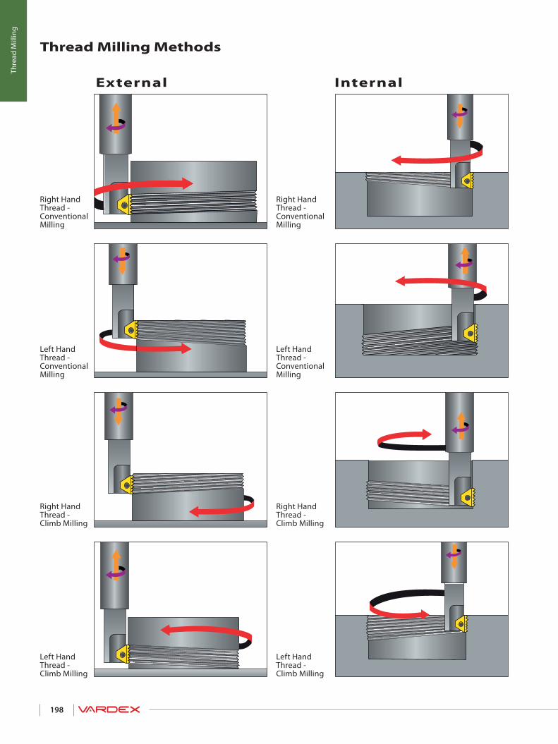
198
Thre
ad M
illin
g
Right Hand Thread - Conventional Milling
Right Hand Thread - Climb Milling
Left Hand Thread - Climb Milling
Left Hand Thread - Climb Milling
Right Hand Thread - Climb Milling
Left Hand Thread - Conventional Milling
Left Hand Thread - Conventional Milling
Right Hand Thread - Conventional Milling
InternalExternal
Thread Milling Methods

D2
L1
ISO - InternalPitch Nominal Dia. Holder Insert L1-Toolholder D2-Tool h min - Thread
Profile depthmm mm Overhang Cutting dia.*
0.7510 TMMC050-6.0 6.0I0.75ISOTM...028/001 0.47 0.35
0.01711 TMMC050-6.0 6.0I0.75ISOTM... 0.47 0.35
1.0
12-14 TMMC050-6.0 6.0I1.0ISOTM.. 0.47 0.35
0.023
15-18 TMC050-2 2I1.0ISOTM2... 0.47 0.4520 TMC0625-3 3I1.0ISOTM2... 0.87 0.6722 BTMC075-3B 3BI1.0ISOTM2... 1.14 0.7524 TMC075-3 3I1.0ISOTM2... 1.69 0.7925-28 TMLC100-3 3I1.0ISOTM2... 0.98 0.8730 TM2C100-3 3I1.0ISOTM2... 1.69 1.02
1.2512 TMMC050-6.0 6.0I1.25ISOTM...028/002 0.47 0.35
0.02814 TMMC050-6.0 6.0I1.25ISOTM... 0.47 0.35
1.5
14-15 TMMC050-6.0 6.0I1.5ISOTM... 0.47 0.35
0.034
16-20 TMC050-2 2I1.5ISOTM2... 0.47 0.4522 TMC0625-3 3I1.5ISOTM2... 0.87 0.6724 BTMC075-3B 3BI1.5ISOTM2... 1.14 0.7525-26 TMC075-3 3I1.5ISOTM2... 1.69 0.7927-30 TMLC100-3 3I1.5ISOTM2... 0.98 0.8732-33 TM2C100-3 3I1.5ISOTM2... 1.69 1.0235-42 TMC100-5 5I1.5ISOTM2... 2.05 1.1845 TMC125-5 5I1.5ISOTM2... 2.28 1.4648-55 TM2C125-5 5I1.5ISOTM2... 1.77 1.6556-68 TMSH-D200-075-3 3I1.5ISOTM2... 1.9770-80 TMSH-D250-075-5 5I1.5ISOTM2... 2.48
1.75 12 TMMC075-6.0 124/203 6.0I1.75ISOTM...028/003 0.59 0.35 0.04
2.0
14-20 TMC050-2 2I2.0ISOTM...028/004 0.47 0.45
0.045
22 TMNC0625-3 3I2.0ISOTM2... 0.87 0.6124 TMC0625-3 3I2.0ISOTM2... 0.87 0.6725 BTMC075-3B 3BI2.0ISOTM2... 1.14 0.7527 TMC075-3 3I2.0ISOTM2... 1.69 0.7928-32 TMLC100-3 3I2.0ISOTM2... 0.98 0.8733-36 TM2C100-3 3I2.0ISOTM2... 1.69 1.0239-42 TMC100-5 5I2.0ISOTM2... 2.05 1.1845-48 TMC125-5 5I2.0ISOTM2... 2.28 1.4650-56 TM2C125-5 5I2.0ISOTM2... 1.77 1.6558-68 TMSH-D200-075-3 3I2.0ISOTM2... 1.9770-85 TMSH-D250-075-5 5I2.0ISOTM2... 2.4890-105 TMSH-D300-100-5 5I2.0ISOTM2... 3.15110-130 TMSH-D400-125-5 5I2.0ISOTM2... 3.94135-150 TMSH-D500-150-5 5I2.0ISOTM2... 4.92
2.520 TMC0625-3 124/201 3I2.5ISOTM...028/005 0.81 0.61
0.05722 TMC100-4 124/202 4I2.5ISOTM...028/006 1.18 0.71
199
Thre
ad M
illin
g
* The recommended holder is the largest for the given thread specification. Holder with smaller or equal cutting diameters (D2) can also be used (Except inserts 028/...).
Tooling recommendation* (For MiTM tools see page 258) (For TMSD tools see page 277) (For TM Solid Carbide tools see page 291)
TM Gen Software
and updated versions
can be downloaded from
www.vargususa.com
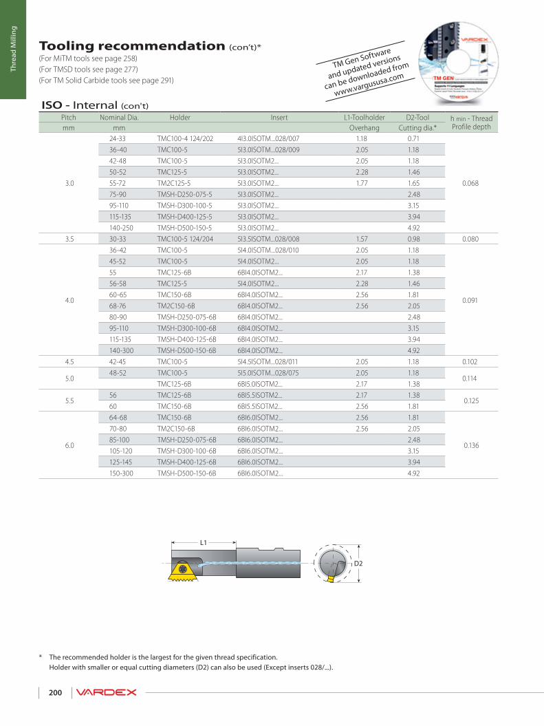
D2
L1
200
Thre
ad M
illin
g
* The recommended holder is the largest for the given thread specification. Holder with smaller or equal cutting diameters (D2) can also be used (Except inserts 028/...).
Tooling recommendation (con’t)* (For MiTM tools see page 258) (For TMSD tools see page 277) (For TM Solid Carbide tools see page 291)
ISO - Internal (con't)Pitch Nominal Dia. Holder Insert L1-Toolholder D2-Tool h min - Thread
Profile depthmm mm Overhang Cutting dia.*
3.0
24-33 TMC100-4 124/202 4I3.0ISOTM...028/007 1.18 0.71
0.068
36-40 TMC100-5 5I3.0ISOTM...028/009 2.05 1.1842-48 TMC100-5 5I3.0ISOTM2... 2.05 1.1850-52 TMC125-5 5I3.0ISOTM2... 2.28 1.4655-72 TM2C125-5 5I3.0ISOTM2... 1.77 1.6575-90 TMSH-D250-075-5 5I3.0ISOTM2... 2.4895-110 TMSH-D300-100-5 5I3.0ISOTM2... 3.15115-135 TMSH-D400-125-5 5I3.0ISOTM2... 3.94140-250 TMSH-D500-150-5 5I3.0ISOTM2... 4.92
3.5 30-33 TMC100-5 124/204 5I3.5ISOTM...028/008 1.57 0.98 0.080
4.0
36-42 TMC100-5 5I4.0ISOTM...028/010 2.05 1.18
0.091
45-52 TMC100-5 5I4.0ISOTM2... 2.05 1.1855 TMC125-6B 6BI4.0ISOTM2... 2.17 1.3856-58 TMC125-5 5I4.0ISOTM2... 2.28 1.4660-65 TMC150-6B 6BI4.0ISOTM2... 2.56 1.8168-76 TM2C150-6B 6BI4.0ISOTM2... 2.56 2.0580-90 TMSH-D250-075-6B 6BI4.0ISOTM2... 2.4895-110 TMSH-D300-100-6B 6BI4.0ISOTM2... 3.15115-135 TMSH-D400-125-6B 6BI4.0ISOTM2... 3.94140-300 TMSH-D500-150-6B 6BI4.0ISOTM2... 4.92
4.5 42-45 TMC100-5 5I4.5ISOTM...028/011 2.05 1.18 0.102
5.048-52 TMC100-5 5I5.0ISOTM...028/075 2.05 1.18
0.114TMC125-6B 6BI5.0ISOTM2... 2.17 1.38
5.556 TMC125-6B 6BI5.5ISOTM2... 2.17 1.38
0.12560 TMC150-6B 6BI5.5ISOTM2... 2.56 1.81
6.0
64-68 TMC150-6B 6BI6.0ISOTM2... 2.56 1.81
0.136
70-80 TM2C150-6B 6BI6.0ISOTM2... 2.56 2.0585-100 TMSH-D250-075-6B 6BI6.0ISOTM2... 2.48105-120 TMSH-D300-100-6B 6BI6.0ISOTM2... 3.15125-145 TMSH-D400-125-6B 6BI6.0ISOTM2... 3.94150-300 TMSH-D500-150-6B 6BI6.0ISOTM2... 4.92
TM Gen Software
and updated versions
can be downloaded from
www.vargususa.com
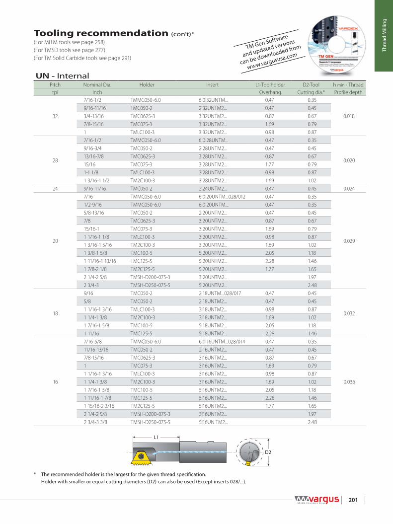
D2
L1
201
Thre
ad M
illin
g
Tooling recommendation (con’t)* (For MiTM tools see page 258) (For TMSD tools see page 277) (For TM Solid Carbide tools see page 291)
* The recommended holder is the largest for the given thread specification. Holder with smaller or equal cutting diameters (D2) can also be used (Except inserts 028/...).
UN - InternalPitch Nominal Dia. Holder Insert L1-Toolholder D2-Tool h min - Thread
tpi Inch Overhang Cutting dia.* Profile depth
32
7/16-1/2 TMMC050-6.0 6.0I32UNTM... 0.47 0.35
0.0189/16-11/16 TMC050-2 2I32UNTM2... 0.47 0.453/4-13/16 TMC0625-3 3I32UNTM2... 0.87 0.677/8-15/16 TMC075-3 3I32UNTM2... 1.69 0.791 TMLC100-3 3I32UNTM2... 0.98 0.87
28
7/16-1/2 TMMC050-6.0 6.0I28UNTM... 0.47 0.35
0.020
9/16-3/4 TMC050-2 2I28UNTM2... 0.47 0.4513/16-7/8 TMC0625-3 3I28UNTM2... 0.87 0.6715/16 TMC075-3 3I28UNTM2... 1.77 0.791-1 1/8 TMLC100-3 3I28UNTM2... 0.98 0.871 3/16-1 1/2 TM2C100-3 3I28UNTM2... 1.69 1.02
24 9/16-11/16 TMC050-2 2I24UNTM2... 0.47 0.45 0.024
20
7/16 TMMC050-6.0 6.0I20UNTM...028/012 0.47 0.35
0.029
1/2-9/16 TMMC050-6.0 6.0I20UNTM... 0.47 0.355/8-13/16 TMC050-2 2I20UNTM2... 0.47 0.457/8 TMC0625-3 3I20UNTM2... 0.87 0.6715/16-1 TMC075-3 3I20UNTM2... 1.69 0.791 1/16-1 1/8 TMLC100-3 3I20UNTM2... 0.98 0.871 3/16-1 5/16 TM2C100-3 3I20UNTM2... 1.69 1.021 3/8-1 5/8 TMC100-5 5I20UNTM2... 2.05 1.181 11/16-1 13/16 TMC125-5 5I20UNTM2... 2.28 1.461 7/8-2 1/8 TM2C125-5 5I20UNTM2... 1.77 1.652 1/4-2 5/8 TMSH-D200-075-3 3I20UNTM2... 1.972 3/4-3 TMSH-D250-075-5 5I20UNTM2... 2.48
18
9/16 TMC050-2 2I18UNTM...028/017 0.47 0.45
0.032
5/8 TMC050-2 2I18UNTM2... 0.47 0.451 1/16-1 3/16 TMLC100-3 3I18UNTM2... 0.98 0.871 1/4-1 3/8 TM2C100-3 3I18UNTM2... 1.69 1.021 7/16-1 5/8 TMC100-5 5I18UNTM2... 2.05 1.181 11/16 TMC125-5 5I18UNTM2... 2.28 1.46
16
7/16-5/8 TMMC050-6.0 6.0I16UNTM...028/014 0.47 0.35
0.036
11/16-13/16 TMC050-2 2I16UNTM2... 0.47 0.457/8-15/16 TMC0625-3 3I16UNTM2... 0.87 0.671 TMC075-3 3I16UNTM2... 1.69 0.791 1/16-1 3/16 TMLC100-3 3I16UNTM2... 0.98 0.871 1/4-1 3/8 TM2C100-3 3I16UNTM2... 1.69 1.021 7/16-1 5/8 TMC100-5 5I16UNTM2... 2.05 1.181 11/16-1 7/8 TMC125-5 5I16UNTM2... 2.28 1.461 15/16-2 3/16 TM2C125-5 5I16UNTM2... 1.77 1.652 1/4-2 5/8 TMSH-D200-075-3 3I16UNTM2... 1.972 3/4-3 3/8 TMSH-D250-075-5 5I16UN TM2... 2.48
TM Gen Software
and updated versions
can be downloaded from
www.vargususa.com

D2
L1
202
Thre
ad M
illin
g
Tooling recommendation (con’t)* (For MiTM tools see page 258) (For TMSD tools see page 277) (For TM Solid Carbide tools see page 291)
* The recommended holder is the largest for the given thread specification. Holder with smaller or equal cutting diameters (D2) can also be used (Except inserts 028/...).
TM Gen Software
and updated versions
can be downloaded from
www.vargususa.com
UN - Internal (con"t)Pitch Nominal Dia. Holder Insert L1-Toolholder D2-Tool h min - Thread
tpi Inch Overhang Cutting dia.* Profile depth16 3 1/2-4 TMSH-D300-100-5 5I16UNTM2... 3.15 0.036
147/16 TMMC075-6.0 124/203 6.0I14UNTM...028/013 0.59 0.35
0.0417/8 TMC050-2 2I14UNTM2... 0.47 0.45
13 1/2 TMC075-2 124/205 2I13UNTM...028/015 0.61 0.39 0.044
12
9/16-11/16 TMC075-2 124/205 2I12UNTM...028/016 0.61 0.39
0.048
3/4 TMNC0625-3 3I12UNTM...028/020 0.87 0.6113/16 TMC0625-3 3I12UNTM...028/020 0.87 0.677/8 TMNC0625-3 3I12UNTM2... 0.87 0.6115/16 TMC0625-3 3I12UNTM2... 0.87 0.671 BTMC075-3B 3BI12UNTM2... 1.14 0.751 1/16 TMC075-3 3I12UNTM2... 1.69 0.791 1/8-1 1/4 TMLC100-3 3I12UNTM2... 0.98 0.871 5/16-1 7/16 TM2C100-3 3I12UNTM2... 1.69 1.021 1/2-1 11/16 TMC100-5 5I12UNTM2... 2.05 1.181 3/4-1 15/16 TMC125-5 5I12UNTM2... 2.28 1.462-2 1/4 TM2C125-5 5I12UNTM2... 1.77 1.652 3/8-2 3/4 TMSH-D200-075-3 3I12UNTM2... 1.972 7/8-3 3/8 TMSH-D250-075-5 5I12UNTM2... 2.483 1/2-4 TMSH-D300-100-5 5I12UNTM2... 3.15
11 5/8 TMC075-2 124/206 2I11UNTM...028/018 0.61 0.47 0.05210 3/4 TMC0625-3 124/201 3I10UNTM...028/019 0.81 0.61 0.0589 7/8 TMC100-4 124/202 4I9UNTM...028/021 1.18 0.71 0.064
8
1-1 3/16 TMC100-4 124/207 4I8UNTM...028/022 1.57 0.79
0.072
1 1/4-1 3/8 TMC100-5 124/204 5I8UNTM...028/024 1.57 0.981 7/16-1 5/8 TMC100-5 5I8UNTM...028/024 2.05 1.181 11/16-1 15/16 TMC100-5 5I8UNTM2... 2.05 1.182-2 1/8 TMC125-5 5I8UNTM2... 2.28 1.462 1/4-2 7/8 TM2C125-5 5I8UNTM2... 1.77 1.653-3 5/8 TMSH-D250-075-5 5I8UNTM2... 2.483 3/4-4 TMSH-D300-100-5 5I8UNTM2... 3.15
7 1 1/8-1 1/4 TMC100-4 124/202 4I7UNTM...028/023 1.18 0.71 0.082
6
1 3/8-1 9/16 TMC100-5 124/204 5I6UNTM...028/025 1.57 0.98
0.096
1 5/8-1 15/16 TMC100-5 5I6UNTM...028/025 2.05 1.182-2 1/8 TMC100-5 5I6UNTM2... 2.05 1.182 1/4 TMC125-5 5I6UNTM2... 2.28 1.462 3/8-2 1/2 TMC150-6B 6BI6UNTM2... 2.56 1.812 5/8-3 1/8 TM2C150-6B 6BI6UNTM2... 2.56 2.053 1/4-3 3/4 TMSH-D250-075-6B 6BI6UNTM2... 2.483 7/8-4 TMSH-D300-100-6B 6BI6UNTM2... 3.15
5 1 3/4 TMC100-5 5I5UNTM...028/077 2.05 1.18 0.1154.5 2-2 1/4 TMC125-6B 6BI4.5UNTM2... 2.17 1.38 0.128
42 1/2 TMC150-6B 6BI4UNTM2... 2.56 1.81
0.1442 3/4-3 TM2C150-6B 6BI4UNTM2... 2.56 2.053 1/4-4 TMSH-D250-075-6B 6BI4UNTM2... 2.48

D2
L1
203
Thre
ad M
illin
g
Tooling recommendation (con’t)* (For MiTM tools see page 258) (For TMSD tools see page 277) (For TM Solid Carbide tools see page 291)
* The recommended holder is the largest for the given thread specification. Holder with smaller or equal cutting diameters (D2) can also be used (Except inserts 028/...).
TM Gen Software
and updated versions
can be downloaded from
www.vargususa.com
UNJ - InternalPitch Nominal Dia. Holder Insert L1-Toolholder D2-Tool h min - Thread
Profile depthtpi Inch Overhang Cutting dia.*24 9/16-11/16 TMC050-2 2I24UNJTM2... 0.47 0.45 0.022
20
1/2 TMMC050-6.0 6.0I20UNJTM... 0.47 0.35
0.0263/4-13/16 TMC050-2 2I20UNJTM2... 0.47 0.457/8 TMC0625-3 3I20UNJTM2... 0.87 0.6715/16-1 TMC075-3 3I20UNJTM2... 1.69 0.79
185/8 TMC050-2 2I18UNJTM2... 0.47 0.45
0.0291 1/16-1 3/16 TMLC100-3 3I18UNJTM2... 0.98 0.871 1/4-1 11/16 TM2C100-3 3I18UNJTM2... 1.69 1.02
16
11/16-13/16 TMC050-2 2I16UNJTM2... 0.47 0.45
0.033
7/8-15/16 TMC0625-3 3I16UNJTM2... 0.87 0.671 TMC075-3 3I16UNJTM2... 1.69 0.791 1/16-1 3/16 TMLC100-3 3I16UNJTM2... 0.98 0.871 1/4-1 3/8 TM2C100-3 3I16UNJTM2... 1.69 1.021 7/16-1 5/8 TMC100-5 5I16UNJTM2... 2.05 1.181 11/16-1 7/8 TMC125-5 5I16UNJTM2... 2.28 1.461 15/16-2 1/8 TM2C125-5 5I16UNJTM2... 1.77 1.652 1/4-2 3/8 TMSH-D200-075-3 3I16UNJTM2... 1.97
14 7/8 TMC050-2 2I14UNJTM2... 0.47 0.45 0.037
12
7/8 TMNC0625-3 3I12UNJTM2... 0.87 0.61
0.044
15/16-1 TMC0625-3 3I12UNJTM2... 0.87 0.671 1/16 TMC075-3 3I12UNJTM2... 1.69 0.791 1/8-1 1/4 TMLC100-3 3I12UNJTM2... 0.98 0.871 5/16-1 7/16 TM2C100-3 3I12UNJTM2... 1.69 1.021 1/2-1 11/16 TMC100-5 5I12UNJTM2... 2.05 1.181 3/4-1 15/16 TMC125-5 5I12UNJTM2... 2.28 1.462-2 1/4 TM2C125-5 5I12UNJTM2... 1.77 1.652 3/8-2 3/4 TMSH-D200-075-3 3I12UNJTM2... 1.972 7/8-3 3/8 TMSH-D250-075-5 5I12UNJTM2... 2.483 1/2-4 1/4 TMSH-D300-100-5 5I12UNJTM2... 3.154 3/8-5 1/4 TMSH-D400-125-5 5I12UNJTM2... 3.945 3/8-6 TMSH-D500-150-5 5I12UNJTM2... 4.92

D2
L1
204
Thre
ad M
illin
g
Tooling recommendation (con’t)* (For MiTM tools see page 258) (For TMSD tools see page 277) (For TM Solid Carbide tools see page 291)
* The recommended holder is the largest for the given thread specification. Holder with smaller or equal cutting diameters (D2) can also be used (Except inserts 028/...).
TM Gen Software
and updated versions
can be downloaded from
www.vargususa.com
W - InternalPitch Nominal Dia. Holder Insert L1-Toolholder D2-Tool h min - Thread
Profile depthtpi Inch Overhang Cutting dia.*
26
7/16 TMMC050-6.0 6.0I26WTM...028/036 0.47 0.35
0.025
1/2-9/16 TMMC050-6.0 6.0EI26WTM... 0.47 0.355/8-3/4 TMC050-2 2EI26WTM2... 0.47 0.4513/16-7/8 TMC0625-3 3EI26WTM2... 0.87 0.6715/16-1 TMC075-3 3EI26WTM2... 1.69 0.791 1/16-1 1/8 TMLC100-3 3EI26WTM2... 0.98 0.871 3/16-1 5/8 TM2C100-3 3EI26WTM2... 1.69 1.021 3/4-2 TMSH-D150-050-2 2EI26WTM2... 1.5
20
1/2 TMMC050-6.0 6.0I20WTM...028/037 0.47 0.35
0.032
9/16 TMMC050-6.0 6.0EI20WTM2... 0.47 0.355/8-13/16 TMC050-2 2EI20WTM2... 0.47 0.457/8-15/16 TMC0625-3 3EI20WTM2... 0.87 0.671 TMC075-3 3EI20WTM2... 1.69 0.791 1/16-1 3/16 TMLC100-3 3EI20WTM2... 0.98 0.871 1/4-1 5/8 TM2C100-3 3EI20WTM2... 1.69 1.021 3/4-2 1/8 TMSH-D150-050-2 2EI20WTM2... 1.52 1/4-3 TMSH-D200-075-3 3EI20WTM2... 1.97
18 7/16 TMMC050-6.0 6.0I18WTM...028/035 0.47 0.35 0.035
16
1/2 TMC075-2 124/205 2I16WTM...028/051 0.61 0.39
0.040
9/16-3/4 TMC050-2 2I16WTM...028/038 0.47 0.4513/16 TMNC0625-3 3EI16WTM2... 0.87 0.617/8-15/16 TMC0625-3 3EI16WTM2... 0.87 0.671-1 1/16 TMC075-3 3EI16WTM2... 1.69 0.791 1/8-1 1/4 TMLC100-3 3EI16WTM2... 0.98 0.871 5/16-1 3/8 TM2C100-3 3EI16WTM2... 1.69 1.021.4-1 5/8 TMC100-5 5EI16WTM2... 2.05 1.181 3/4-1.9 TMC125-5 5EI16WTM2... 2.28 1.462 -2 1/4 TM2C125-5 5EI16WTM2... 1.77 1.652 3/8-2 3/4 TMSH-D200-075-3 3EI16WTM2... 1.972 7/8-3 3/8 TMSH-D250-075-5 5EI16WTM2... 2.483 1/2-4 1/8 TMSH-D300-100-5 5EI16WTM2... 3.154 1/4-5 1/8 TMSH-D400-125-5 5EI16WTM2... 3.945 1/4-7 TMSH-D500-150-5 5EI16WTM2... 4.92
14 5/8-11/16 TMC075-2 124/206 2I14WTM..028/039 0.61 0.47 0.046
12
3/4 TMC0625-3 124/201 3I12WTM...028/040 0.81 0.61
0.054
13/16 TMC0625-3 3I12WTM...028/041 0.87 0.6715/16-1 5/16 TMC075-3 3I12WTM...028/041 1.69 0.791 3/8-1 7/16 TMC100-5 5I12WTM...028/050 2.05 1.181 1/2-1 3/4 TMC100-5 5EI12WTM2... 2.05 1.181 7/8 TMC125-5 5EI12WTM2... 2.28 1.462-2 1/4 TM2C125-5 5EI12WTM2... 1.77 1.65

D2
L1
205
Thre
ad M
illin
g
Tooling recommendation (con’t)* (For MiTM tools see page 258) (For TMSD tools see page 277) (For TM Solid Carbide tools see page 291)
* The recommended holder is the largest for the given thread specification. Holder with smaller or equal cutting diameters (D2) can also be used (Except inserts 028/...).
TM Gen Software
and updated versions
can be downloaded from
www.vargususa.com
W - Internal (con't)Pitch Nominal Dia. Holder Insert L1-Toolholder D2-Tool h min - Thread
Profile depthtpi Inch Overhang Cutting dia.*
12
2 3/8 -2 3/4 TMSH-D200-075-3 3EI12WTM2... 1.97
0.0542 7/8-3 3/8 TMSH-D250-075-5 5EI12WTM2... 2.483 1/2-4 1/8 TMSH-D300-100-5 5EI12WTM2... 3.154 1/4-5 1/8 TMSH-D400-125-5 5EI12WTM2... 3.945 1/4-7 TMSH-D500-150-5 5EI12WTM2... 4.92
11 7/8 TMC100-4 124/202 4I11WTM...028/043 1.18 0.71 0.05810 1 TMC100-4 124/202 4I10WTM...028/045 1.18 0.71 0.0649 7/8-1 1/4 TMC100-4 124/202 4I9WTM...028/042 1.18 0.71 0.071
8
1 TMC100-4 124/202 4I8WTM...028/044 1.18 0.71
0.080
1 3/16-1.4 TMC100-5 124/204 5I8WTM...028/047 1.57 0.981 7/16-1 5/8 TMC100-5 5I8WTM...028/047 2.05 1.181 7/8-1.9 TMC100-5 5EI8WTM2... 2.05 1.182.1-2 1/8 TMC125-5 5EI8WTM2... 2.28 1.462 1/4-3 TM2C125-5 5EI8WTM2... 1.77 1.653 1/8-3 5/8 TMSH-D250-075-5 5EI8WTM2... 2.483 3/4-4 3/8 TMSH-D300-100-5 5EI8WTM2... 3.154 5/8-5 1/2 TMSH-D400-125-5 5EI8WTM2... 3.945 5/8-7 TMSH-D500-150-5 5EI8WTM2... 4.92
7
1 1/8 TMC100-5 124/208 5I7WTM...028/046 1.57 0.87
0.0911 1/4 TMC100-5 124/204 5I7WTM...028/048 1.57 0.981 3/4 TMC100-5 5I7WTM...028/048 2.05 1.182 TMC100-5 5EI7WTM2... 2.05 1.18
6
1 5/16-1 1/2 TMC100-5 124/204 5I6WTM...028/049 1.57 0.98
0.107
1.6-1 5/8 TMC100-5 5I6WTM...028/049 2.05 1.181 7/8-1.9 TMC125-5 5I6WTM...028/049 2.28 1.462.1-2 1/8 TMC100-5 5EI6WTM2... 2.05 1.182 1/4 TMC125-6B 6BEI6WTM2... 2.17 1.382 3/8-2.6 TMC125-5 5EI6WTM2... 2.28 1.462 5/8-2 3/4 TMC150-6B 6BEI6WTM2... 2.56 1.812 7/8-3 1/4 TM2C150-6B 6BEI6WTM2... 2.56 2.053 3/8-3 7/8 TMSH-D250-075-6B 6BEI6WTM2... 2.484-4 3/4 TMSH-D300-100-6B 6BEI6WTM2... 3.154 7/8-5 3/4 TMSH-D400-125-6B 6BEI6WTM2... 3.945 7/8-7 TMSH-D500-150-6B 6BEI6WTM2... 4.92
53 TMC150-6B 6BEI5WTM2... 2.56 1.81
0.1283 1/4 TM2C150-6B 6BEI5WTM2... 2.56 2.05
4.53 1/2 TMC150-6B 6BEI4.5WTM2... 2.56 1.81
0.1423 3/4-4 TM2C150-6B 6BEI4.5WTM2... 2.56 2.05

D2
L1
206
Thre
ad M
illin
g
Tooling recommendation (con’t)* (For MiTM tools see page 258) (For TMSD tools see page 277) (For TM Solid Carbide tools see page 291)
* The recommended holder is the largest for the given thread specification. Holder with smaller or equal cutting diameters (D2) can also be used (Except inserts 028/...).
TM Gen Software
and updated versions
can be downloaded from
www.vargususa.com
NPT - InternalPitch Nominal Dia. Holder Insert L1-Toolholder D2-Tool h min - Thread
Profile depthtpi Inch Overhang Cutting dia.*18 1/4-3/8 TMC075-2 124/209 2I18NPTTM...028/074 0.61 0.39 0.040
141/2 TMNC0625-3 3EI14NPTTM... 0.87 0.61
0.0523/4 TMNC075-3 3EI14NPTTM... 0.91 0.75
11.51 TMNC075-3 3EI11.5NPTTM... 0.91 0.75
0.0651 1/4 TMC100-5 5EI11.5NPTTM... 2.05 1.181 1/2-2 TMNC125-5 5EI11.5NPTTM... 2.28 1.46
82 1/2 TMNC125-5 5EI8NPTTM... 2.28 1.46
0.0953-24 TMC150-6B 6BEI8NPTTM... 2.56 1.81
BSPT - InternalPitch Nominal Dia. Holder Insert L1-Toolholder D2-Tool h min - Thread
Profile depthtpi Inch Overhang Cutting dia.*19 3/8 TMC075-2 2EI19BSPTTM... 0.79 0.45 0.03414 1/2-3/4 TMNC0625-3 3EI14BSPTTM... 0.87 0.61 0.046
111-1 1/4 TMNC075-3 3EI11BSPTTM... 0.91 0.75
0.0581 1/2 TMC100-5 5EI11BSPTTM... 2.05 1.182-6 TMNC125-5 5EI11BSPTTM... 2.28 1.46
BSP - InternalPitch Nominal Dia. Holder Insert L1-Toolholder D2-Tool h min - Thread
Profile depthtpi Inch Overhang Cutting dia.*
191/4 TMMC075-6.0 6.0EI19WTM... 0.67 0.35
0.0343/8 TMC075-2 2EI19WTM2... 0.79 0.45
141/2-5/8 TMC075-2 2EI14WTM2... 0.79 0.45
0.0463/4-7/8 TMC0625-3 3EI14WTM2... 0.87 0.67
11
1 TMC100-5 124/204 5EI11WTM2... 1.57 0.98
0.058
1 1/4-1 1/2 TMC100-5 5EI11WTM2... 2.05 1.181 3/4 TMC125-5 5EI11WTM2... 2.28 1.462-2 1/4 TM2C125-5 5EI11WTM2... 1.77 1.652 1/2-3 TMSH-D250-075-5 5EI11WTM2... 2.483 1/2 TMSH-D300-100-5 5EI11WTM2... 3.154 TMSH-D400-125-5 5EI11WTM2... 3.945-6 TMSH-D500-150-5 5EI11WTM2... 4.92
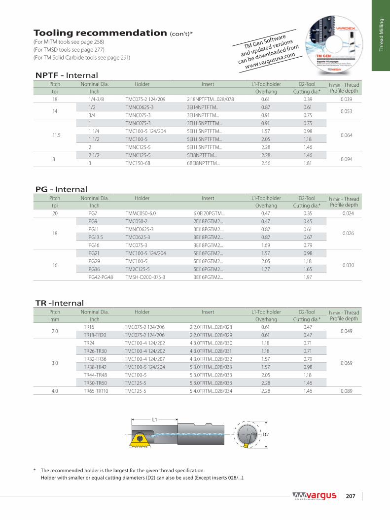
D2
L1
207
Thre
ad M
illin
g
Tooling recommendation (con’t)* (For MiTM tools see page 258) (For TMSD tools see page 277) (For TM Solid Carbide tools see page 291)
* The recommended holder is the largest for the given thread specification. Holder with smaller or equal cutting diameters (D2) can also be used (Except inserts 028/...).
TM Gen Software
and updated versions
can be downloaded from
www.vargususa.com
TR -InternalPitch Nominal Dia. Holder Insert L1-Toolholder D2-Tool h min - Thread
Profile depthmm Inch Overhang Cutting dia.*
2.0TR16 TMC075-2 124/206 2I2.0TRTM...028/028 0.61 0.47
0.049TR18-TR20 TMC075-2 124/206 2I2.0TRTM...028/029 0.61 0.47
3.0
TR24 TMC100-4 124/202 4I3.0TRTM...028/030 1.18 0.71
0.069
TR26-TR30 TMC100-4 124/202 4I3.0TRTM...028/031 1.18 0.71TR32-TR36 TMC100-4 124/207 4I3.0TRTM...028/032 1.57 0.79TR38-TR42 TMC100-5 124/204 5I3.0TRTM...028/033 1.57 0.98TR44-TR48 TMC100-5 5I3.0TRTM...028/033 2.05 1.18TR50-TR60 TMC125-5 5I3.0TRTM...028/033 2.28 1.46
4.0 TR65-TR110 TMC125-5 5I4.0TRTM...028/034 2.28 1.46 0.089
PG - InternalPitch Nominal Dia. Holder Insert L1-Toolholder D2-Tool h min - Thread
Profile depthtpi Inch Overhang Cutting dia.*20 PG7 TMMC050-6.0 6.0EI20PGTM... 0.47 0.35 0.024
18
PG9 TMC050-2 2EI18PGTM2... 0.47 0.45
0.026PG11 TMNC0625-3 3EI18PGTM2... 0.87 0.61PG13.5 TMC0625-3 3EI18PGTM2... 0.87 0.67PG16 TMC075-3 3EI18PGTM2... 1.69 0.79
16
PG21 TMC100-5 124/204 5EI16PGTM2... 1.57 0.98
0.030PG29 TMC100-5 5EI16PGTM2... 2.05 1.18PG36 TM2C125-5 5EI16PGTM2... 1.77 1.65PG42-PG48 TMSH-D200-075-3 3EI16PGTM2... 1.97
NPTF - InternalPitch Nominal Dia. Holder Insert L1-Toolholder D2-Tool h min - Thread
Profile depthtpi Inch Overhang Cutting dia.*18 1/4-3/8 TMC075-2 124/209 2I18NPTFTM...028/078 0.61 0.39 0.039
141/2 TMNC0625-3 3EI14NPTFTM.. 0.87 0.61
0.0533/4 TMNC075-3 3EI14NPTFTM... 0.91 0.75
11.5
1 TMNC075-3 3EI11.5NPTFTM... 0.91 0.75
0.0641 1/4 TMC100-5 124/204 5EI11.5NPTFTM... 1.57 0.981 1/2 TMC100-5 5EI11.5NPTFTM... 2.05 1.182 TMNC125-5 5EI11.5NPTFTM... 2.28 1.46
82 1/2 TMNC125-5 5EI8NPTFTM... 2.28 1.46
0.0943 TMC150-6B 6BEI8NPTFTM... 2.56 1.81
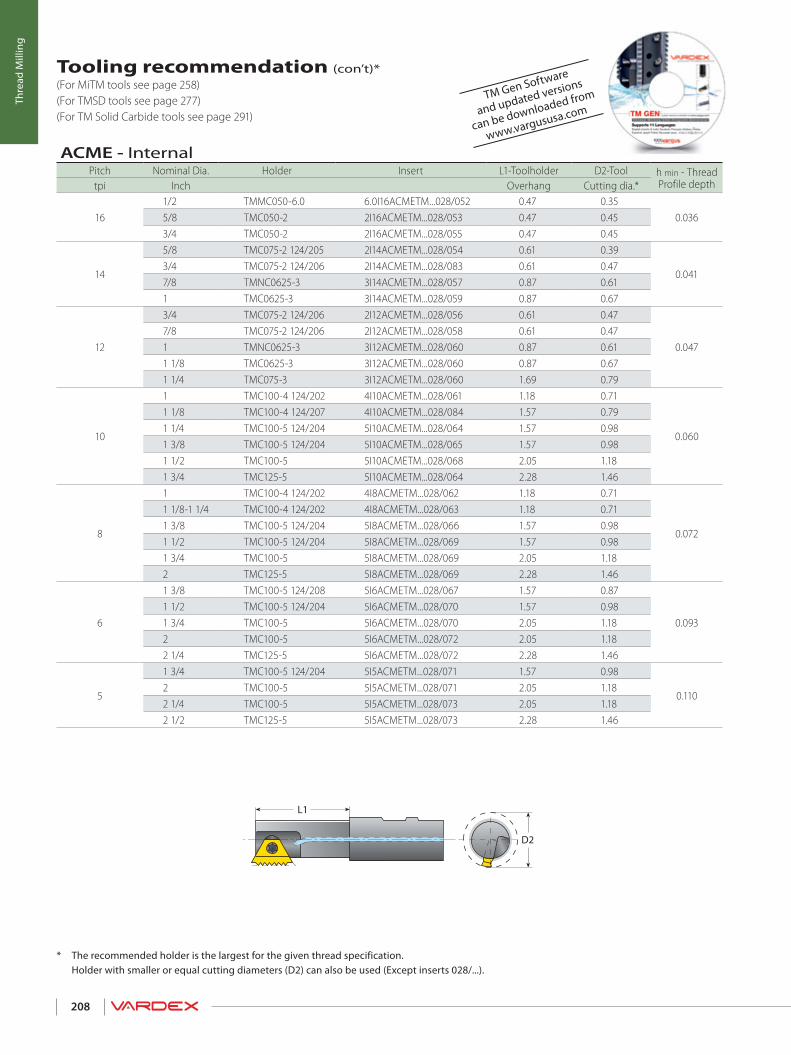
D2
L1
208
Thre
ad M
illin
g
Tooling recommendation (con’t)* (For MiTM tools see page 258) (For TMSD tools see page 277) (For TM Solid Carbide tools see page 291)
* The recommended holder is the largest for the given thread specification. Holder with smaller or equal cutting diameters (D2) can also be used (Except inserts 028/...).
TM Gen Software
and updated versions
can be downloaded from
www.vargususa.com
ACME - InternalPitch Nominal Dia. Holder Insert L1-Toolholder D2-Tool h min - Thread
Profile depthtpi Inch Overhang Cutting dia.*
161/2 TMMC050-6.0 6.0I16ACMETM...028/052 0.47 0.35
0.0365/8 TMC050-2 2I16ACMETM...028/053 0.47 0.453/4 TMC050-2 2I16ACMETM...028/055 0.47 0.45
14
5/8 TMC075-2 124/205 2I14ACMETM...028/054 0.61 0.39
0.0413/4 TMC075-2 124/206 2I14ACMETM...028/083 0.61 0.477/8 TMNC0625-3 3I14ACMETM...028/057 0.87 0.611 TMC0625-3 3I14ACMETM...028/059 0.87 0.67
12
3/4 TMC075-2 124/206 2I12ACMETM...028/056 0.61 0.47
0.0477/8 TMC075-2 124/206 2I12ACMETM...028/058 0.61 0.471 TMNC0625-3 3I12ACMETM...028/060 0.87 0.611 1/8 TMC0625-3 3I12ACMETM...028/060 0.87 0.671 1/4 TMC075-3 3I12ACMETM...028/060 1.69 0.79
10
1 TMC100-4 124/202 4I10ACMETM...028/061 1.18 0.71
0.060
1 1/8 TMC100-4 124/207 4I10ACMETM...028/084 1.57 0.791 1/4 TMC100-5 124/204 5I10ACMETM...028/064 1.57 0.981 3/8 TMC100-5 124/204 5I10ACMETM...028/065 1.57 0.981 1/2 TMC100-5 5I10ACMETM...028/068 2.05 1.181 3/4 TMC125-5 5I10ACMETM...028/064 2.28 1.46
8
1 TMC100-4 124/202 4I8ACMETM...028/062 1.18 0.71
0.072
1 1/8-1 1/4 TMC100-4 124/202 4I8ACMETM...028/063 1.18 0.711 3/8 TMC100-5 124/204 5I8ACMETM...028/066 1.57 0.981 1/2 TMC100-5 124/204 5I8ACMETM...028/069 1.57 0.981 3/4 TMC100-5 5I8ACMETM...028/069 2.05 1.182 TMC125-5 5I8ACMETM...028/069 2.28 1.46
6
1 3/8 TMC100-5 124/208 5I6ACMETM...028/067 1.57 0.87
0.0931 1/2 TMC100-5 124/204 5I6ACMETM...028/070 1.57 0.981 3/4 TMC100-5 5I6ACMETM...028/070 2.05 1.182 TMC100-5 5I6ACMETM...028/072 2.05 1.182 1/4 TMC125-5 5I6ACMETM...028/072 2.28 1.46
5
1 3/4 TMC100-5 124/204 5I5ACMETM...028/071 1.57 0.98
0.1102 TMC100-5 5I5ACMETM...028/071 2.05 1.182 1/4 TMC100-5 5I5ACMETM...028/073 2.05 1.182 1/2 TMC125-5 5I5ACMETM...028/073 2.28 1.46

Thread Milling> Standard Inserts

210
THre
ad M
illin
gIn
sert
s
Vardex Ordering Code SystemThread Milling Inserts
THREAD MILLING INSERTS
VARDEX Ordering Code System .............................................................................................................................................. Page 210
American UN Standard TM Inserts ........................................................................................................................................ Page 211
American UN (Internal) Coarse Pitch TM Inserts ........................................................................................................... Page 213
American UN Standard TM Inserts for TMO Toolholders ......................................................................................... Page 215
American UN Fine Pitch TM Inserts ....................................................................................................................................... Page 217
UNJ Standard TM Insert ................................................................................................................................................................ Page 218
ISO Metric Standard TM Inserts ............................................................................................................................................... Page 219
ISO Metric (Internal) Coarse Pitch TM Inserts .................................................................................................................. Page 221
ISO Metric Standard TM Inserts for TMO Toolholders ................................................................................................ Page 222
ISO Metric Fine Pitch TM Inserts .............................................................................................................................................. Page 223
NPT Standard TM Inserts .............................................................................................................................................................. Page 224
NPT (Internal) Coarse Pitch TM Inserts ................................................................................................................................ Page 224
NPTF (Dry Seal) Standard TM Inserts .................................................................................................................................... Page 225
NPTF (Dry Seal-Internal) Coarse Pitch TM Inserts ......................................................................................................... Page 225
NPS Standard TM Inserts .............................................................................................................................................................. Page 226
BSPT Standard TM Inserts ............................................................................................................................................................ Page 226
Pg Standard TM Inserts ................................................................................................................................................................. Page 227
W for BSW, BSP Standard TM Inserts ..................................................................................................................................... Page 228
W for BSW only Coarse Pitch TM Inserts ............................................................................................................................ Page 229
W for BSW, BSP Standard TM Inserts For TMO Toolholders .................................................................................... Page 231
ACME (Internal) Coarse Pitch TM Inserts ............................................................................................................................ Page 232
TR (Internal) Coarse Pitch TM Inserts .................................................................................................................................... Page 233
8 - Carbide gradeVBX VTXVK2
9 - Coarse Pitch Inserts028/...
7 - Pitch TypeF = Fine Pitch
6 - SystemTM2 TM
5 - Standard
ISO- ISO MetricUN- American UNUNJ- UNJW- Whitworth for BSW, BSPNPT - NPTNPTF- NPTFNPS- NPS
BSPT- British Standard Pipe ThreadPG- Pg DIN 40430ACME- ACMETR- Trapez DIN 103
4 - Pitch80 - 4(tpi)0.35 - 6.0 (mm)
3 - Type of Insert
E - ExternalI - InternalEI - External + Internal
2 - Cutting Edge LengthB - TMB
1- Insert Size6.0 - 6.0 mm2 - ¼”3 - 3/8”3B - 3/8”B4 - ½”5 - 5/8”6B - ¾”B
028/...9
VBX8
F7
TM26
UN5
124
I3
B2
31
IC
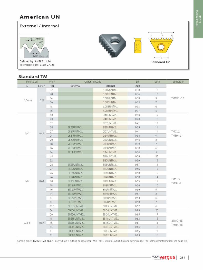
LLe
IC
1/4P60°
1/8P
211
THre
ad M
illin
gIn
sert
s
Defined by: ANSI B1.1.74Tolerance class: Class 2A/2B
Standard TM
External / Internal
American UN
External
Internal
Sample order: 3E24UNTM2 VBX All inserts have 2 cutting edges, except MiniTM (IC 6.0 mm), which has one cutting edge. For toolholder information, see page 236.
Standard TMInsert Size Pitch Ordering Code Le Teeth ToolholderIC L inch tpi External Internal inch
TMMC..-6.06.0mm 0.41
32 6.0I32UNTM... 0.38 1228 6.0I28UNTM... 0.36 1024 6.0I24UNTM... 0.38 920 6.0I20UNTM... 0.35 718 6.0I18UNTM... 0.33 616 6.0I16UNTM... 0.31 5
1/4” 0.43
48 2I48UNTM2... 0.40 19
TMC..-2TMSH..-2
40 2I40UNTM2... 0.40 1632 2I32UNTM2... 0.41 1328 2E28UNTM2... 2I28UNTM2... 0.39 1127 2E27UNTM2... 2I27UNTM2... 0.41 1124 2E24UNTM2... 2I24UNTM2... 0.38 920 2E20UNTM2... 2I20UNTM2... 0.40 818 2E18UNTM2... 2I18UNTM2... 0.39 716 2E16UNTM2... 2I16UNTM2... 0.38 614 2E14UNTM2... 2I14UNTM2... 0.36 5
3/8” 0.63
40 3I40UNTM2... 0.58 23
TMC..-3TMSH..-3
32 3I32UNTM2... 0.59 1928 3E28UNTM2... 3I28UNTM2... 0.57 1627 3E27UNTM2... 3I27UNTM2... 0.56 1526 3E26UNTM2... 3I26UNTM2... 0.58 1524 3E24UNTM2... 3I24UNTM2... 0.58 1420 3E20UNTM2... 3I20UNTM2... 0.55 1118 3E18UNTM2... 3I18UNTM2... 0.56 1016 3E16UNTM2... 3I16UNTM2... 0.56 914 3E14UNTM2... 3I14UNTM2... 0.57 813 3E13UNTM2... 3I13UNTM2... 0.54 612 3E12UNTM2... 3I12UNTM2... 0.58 711.5 3E11.5UNTM2... 3I11.5UNTM2... 0.52 6
3/8”B 0.87
24 3BE24UNTM2... 3BI24UNTM2... 0.83 20
BTMC..-3BTMSH..-3B
20 3BE20UNTM2... 3BI20UNTM2... 0.85 1718 3BE18UNTM2... 3BI18UNTM2... 0.83 1516 3BE16UNTM2... 3BI16UNTM2... 0.81 1314 3BE14UNTM2... 3BI14UNTM2... 0.86 1213 3BE13UNTM2... 3BI13UNTM2... 0.85 1112 3BE12UNTM2... 3BI12UNTM2... 0.83 10

LLe
IC
1/4P60°
1/8P
212
THre
ad M
illin
gIn
sert
s
Defined by: ANSI B1.1.74Tolerance class: Class 2A/2B
Standard TM
External / Internal
American UN (con't)
External
Internal
Sample order: 5E24UNTM2 VBXAll inserts have 2 cutting edges, except MiniTM (IC 6.0 mm), which has one cutting edge.For toolholder information, see page 236.
Standard TMInsert Size Pitch Ordering Code Le Teeth ToolholderIC L inch tpi External Internal inch
TMC..-5TMSH..-55/8” 1.06
24 5E24UNTM2... 5I24UNTM2... 1.00 2420 5E20UNTM2... 5I20UNTM2... 1.00 2018 5E18UNTM2... 5I18UNTM2... 1.00 1816 5E16UNTM2... 5I16UNTM2... 1.00 1614 5E14UNTM2... 5I14UNTM2... 1.00 1413 5E13UNTM2... 5I13UNTM2... 1.00 1312 5E12UNTM2... 5I12UNTM2... 1.00 1211.5 5E11.5UNTM2... 5I11.5UNTM2... 0.96 1111 5E11UNTM2... 5I11UNTM2... 1.00 1110 5E10UNTM2... 0.90 910 5I10UNTM2... 1.00 109 5E9UNTM2... 5I9UNTM2... 0.89 88 5E8UNTM2... 5I8UNTM2... 0.88 77 5E7UNTM2... 0.86 67 5I7UNTM2... 1.00 76 5E6UNTM2... 0.83 56 5I6UNTM2... 1.00 6
3/4”B 1.52
6 6BE6UNTM2... 6BI6UNTM2... 1.53 8TMC..-6BTMSH..-6B
5 6BE5UNTM2... 6BI5UNTM2... 1.20 64.5 6BE4.5UNTM2... 6BI4.5UNTM2... 1.33 64 6BE4UNTM2... 6BI4UNTM2... 1.25 5
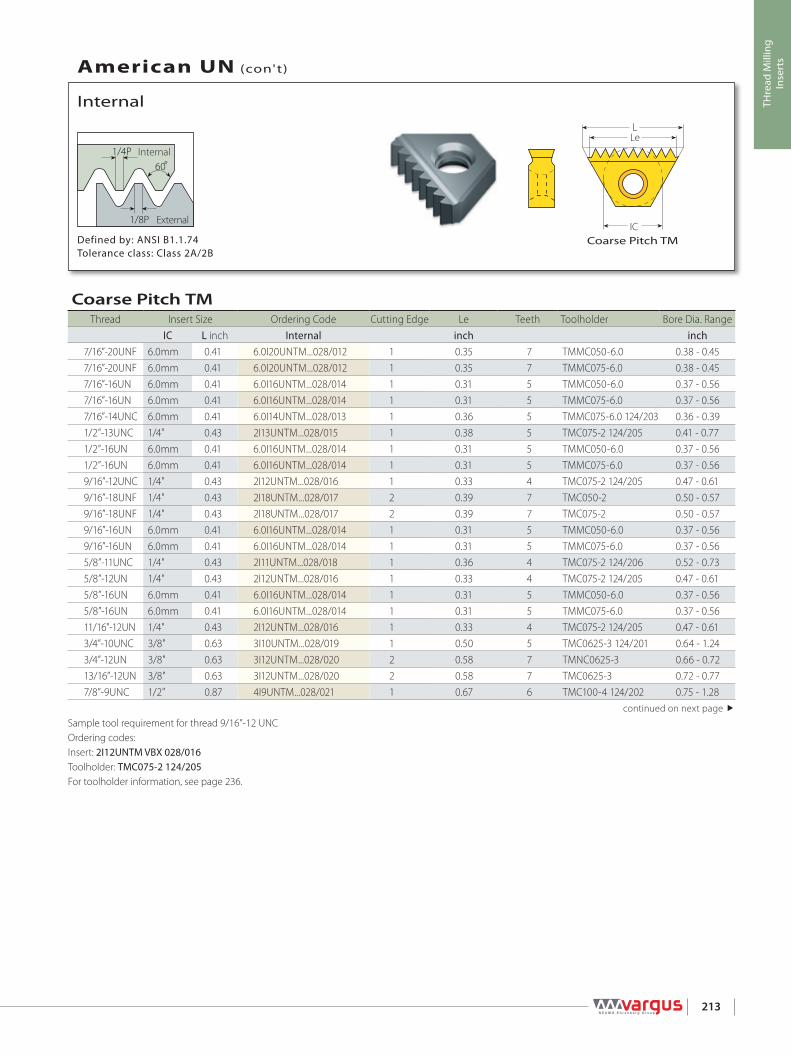
LLe
IC
1/4P60°
1/8P
213
THre
ad M
illin
gIn
sert
s
Defined by: ANSI B1.1.74Tolerance class: Class 2A/2B
Coarse Pitch TM
Internal
American UN (con't)
External
Internal
Sample tool requirement for thread 9/16”-12 UNCOrdering codes:Insert: 2I12UNTM VBX 028/016Toolholder: TMC075-2 124/205For toolholder information, see page 236.
Coarse Pitch TMThread Insert Size Ordering Code Cutting Edge Le Teeth Toolholder Bore Dia. Range
IC L inch Internal inch inch7/16”-20UNF 6.0mm 0.41 6.0I20UNTM...028/012 1 0.35 7 TMMC050-6.0 0.38 - 0.457/16”-20UNF 6.0mm 0.41 6.0I20UNTM...028/012 1 0.35 7 TMMC075-6.0 0.38 - 0.457/16”-16UN 6.0mm 0.41 6.0I16UNTM...028/014 1 0.31 5 TMMC050-6.0 0.37 - 0.567/16”-16UN 6.0mm 0.41 6.0I16UNTM...028/014 1 0.31 5 TMMC075-6.0 0.37 - 0.567/16”-14UNC 6.0mm 0.41 6.0I14UNTM...028/013 1 0.36 5 TMMC075-6.0 124/203 0.36 - 0.391/2”-13UNC 1/4" 0.43 2I13UNTM...028/015 1 0.38 5 TMC075-2 124/205 0.41 - 0.771/2”-16UN 6.0mm 0.41 6.0I16UNTM...028/014 1 0.31 5 TMMC050-6.0 0.37 - 0.561/2”-16UN 6.0mm 0.41 6.0I16UNTM...028/014 1 0.31 5 TMMC075-6.0 0.37 - 0.569/16”-12UNC 1/4" 0.43 2I12UNTM...028/016 1 0.33 4 TMC075-2 124/205 0.47 - 0.619/16”-18UNF 1/4" 0.43 2I18UNTM...028/017 2 0.39 7 TMC050-2 0.50 - 0.579/16”-18UNF 1/4" 0.43 2I18UNTM...028/017 2 0.39 7 TMC075-2 0.50 - 0.579/16”-16UN 6.0mm 0.41 6.0I16UNTM...028/014 1 0.31 5 TMMC050-6.0 0.37 - 0.569/16”-16UN 6.0mm 0.41 6.0I16UNTM...028/014 1 0.31 5 TMMC075-6.0 0.37 - 0.565/8”-11UNC 1/4" 0.43 2I11UNTM...028/018 1 0.36 4 TMC075-2 124/206 0.52 - 0.735/8”-12UN 1/4" 0.43 2I12UNTM...028/016 1 0.33 4 TMC075-2 124/205 0.47 - 0.615/8”-16UN 6.0mm 0.41 6.0I16UNTM...028/014 1 0.31 5 TMMC050-6.0 0.37 - 0.565/8”-16UN 6.0mm 0.41 6.0I16UNTM...028/014 1 0.31 5 TMMC075-6.0 0.37 - 0.5611/16”-12UN 1/4" 0.43 2I12UNTM...028/016 1 0.33 4 TMC075-2 124/205 0.47 - 0.613/4”-10UNC 3/8" 0.63 3I10UNTM...028/019 1 0.50 5 TMC0625-3 124/201 0.64 - 1.243/4”-12UN 3/8" 0.63 3I12UNTM...028/020 2 0.58 7 TMNC0625-3 0.66 - 0.7213/16”-12UN 3/8" 0.63 3I12UNTM...028/020 2 0.58 7 TMC0625-3 0.72 - 0.777/8”-9UNC 1/2" 0.87 4I9UNTM...028/021 1 0.67 6 TMC100-4 124/202 0.75 - 1.28
continued on next page

LLe
IC
1/4P60º
1/8P
214
THre
ad M
illin
gIn
sert
s
Defined by: ANSI B1.1.74Tolerance class: Class 2A/2B
Coarse Pitch TM
Internal
American UN (con't)
External
Internal
Sample tool requirement for thread 1 9/16”-6 UNOrdering codes:Insert: 5I6UNTM VBX 028/025Toolholder: TMC 100-5 124/204For toolholder information, see page 236.
Coarse Pitch TM (con't)
Thread Insert Size Ordering Code Cutting Edge Le Teeth Toolholder Bore Dia. RangeIC L inch Internal inch inch
1” - 8UNC 1/2" 0.87 4I8UNTM...028/022 1 0.75 6 TMC100 - 4 124/207 0.86 - 1.111 1/16”-8UN 1/2" 0.87 4I8UNTM...028/022 1 0.75 6 TMC100-4 124/207 0.86 - 1.111 1/8”-7UNC 1/2" 0.87 4I7UNTM...028/023 1 0.71 5 TMC100-4 124/202 0.97 - 1.411 1/8”-8UN 1/2" 0.87 4I8UNTM...028/022 1 0.75 6 TMC100-4 124/207 0.86 - 1.111 3/16”-8UN 1/2" 0.87 4I8UNTM...028/022 1 0.75 6 TMC100-4 124/207 0.86 - 1.111 1/4”-7UNC 1/2" 0.87 4I7UNTM...028/023 1 0.71 5 TMC100-4 124/202 0.97 - 1.411 1/4”-8UN 5/8" 1.06 5I8UNTM...028/024 2 0.88 7 TMC100-5 124/204 1.11 - 1.301 5/16”-8UN 5/8" 1.06 5I8UNTM...028/024 2 0.88 7 TMC100-5 124/204 1.11 - 1.301 3/8”-6UNC 5/8" 1.06 5I6UNTM...028/025 2 1.00 6 TMC100-5 124/204 1.19 - 1.441 3/8”-8UN 5/8" 1.06 5I8UNTM...028/024 2 0.88 7 TMC100-5 124/204 1.11 - 1.301 7/16”-6UN 5/8" 1.06 5I6UNTM...028/025 2 1.00 6 TMC100-5 124/204 1.19 - 1.441 7/16”-8UN 5/8" 1.06 5I8UNTM...028/024 2 0.88 7 TMC100-5 1.30 - 1.541 1/2”-6UNC 5/8" 1.06 5I6UNTM...028/025 2 1.00 6 TMC100-5 124/204 1.19 - 1.441 1/2”-8UN 5/8” 1.06 5I8UNTM...028/024 2 0.88 7 TMC100-5 1.30 - 1.541 9/16” -6UN 5/8" 1.06 5I6UNTM...028/025 2 1.00 6 TMC100-5 124/204 1.19 - 1.441 9/16”-8UN 5/8" 1.06 5I8UNTM...028/024 2 0.88 7 TMC100-5 1.30 - 1.541 5/8”-6UN 5/8" 1.06 5I6UNTM...028/025 2 1.00 6 TMC100-5 1.44 - 1.771 5/8”-8UN 5/8" 1.06 5I8UNTM...028/024 2 0.88 7 TMC100-5 1.30 - 1.541 11/16”-6UN 5/8" 1.06 5I6UNTM...028/025 2 1.00 6 TMC100-5 1.44 - 1.771 3/4”-5UNC 5/8" 1.06 5I5UNTM...028/077 2 0.80 4 TMC100-5 1.53 - ∞1 3/4”-6UN 5/8" 1.06 5I6UNTM...028/025 2 1.00 6 TMC100-5 1.44 - 1.771 13/16”-6UN 5/8" 1.06 5I6UNTM...028/025 2 1.00 6 TMC100-5 1.44 - 1.771 7/8”-6UN 5/8" 1.06 5I6UNTM...028/025 2 1.00 6 TMC100-5 1.44 - 1.771 15/16”-6UN 5/8" 1.06 5I6UNTM...028/025 2 1.00 6 TMC100-5 1.44 - 1.77

LLe
IC
1/4P
60°
1/8P
ECL
215
THre
ad M
illin
gIn
sert
s
ECL - The Effective Cutting Length
Defined by: ANSI B1.1.74Tolerance class: Class 2A/2B
Standard TM
External / Internal
American UN (con't)
External
Internal
Sample order: 2E16UNTM2 VBXFor Le and number of teeth of the above inserts, see the table for standard inserts on page 211-212.For toolholder intormation, see page 236.
Standard TM Inserts for TMO ToolholdersInsert Size Pitch Ordering Code Toolholder ECL
IC L inch tpi External Internal TMO inch
1/4” 0.43
48 2I48UNTM2... TMOC075-2-1 0.7748 2I48UNTM2... TMOC075-2-2 0.7348 2I48UNTM2... TMOC075-2-9 0.7532 2I32UNTM2... TMOC075-2-1 0.7828 2E28UNTM2... 2I28UNTM2... TMOC075-2-3 0.6824 2E24UNTM2... 2I24UNTM2... TMOC075-2-2 0.7120 2E20UNTM2... 2I20UNTM2... TMOC075-2-4 0.7518 2E18UNTM2... 2I18UNTM2... TMOC075-2-2 0.7216 2E16UNTM2... 2I16UNTM2... TMOC075-2-1 0.7514 2E14UNTM2... 2I14UNTM2... TMOC075-2-3 0.64
3/8” 0.63
32 3I32UNTM2... TMOC075-3-3 1.0932 3I32UNTM2... TMOC075-3-11 1.1328 3E28UNTM2... 3I28UNTM2... TMOC075-3-3 1.0727 3E27UNTM2... 3I27UNTM2... TMOC075-3-4 1.0724 3E24UNTM2... 3I24UNTM2... TMOC075-3-6 1.0820 3E20UNTM2... 3I20UNTM2... TMOC075-3-6 1.0518 3E18UNTM2... 3I18UNTM2... TMOC075-3-6 1.0616 3E16UNTM2... 3I16UNTM2... TMOC075-3-6 1.0614 3E14UNTM2... 3I14UNTM2... TMOC075-3-6 1.0713 3E13UNTM2... 3I13UNTM2... TMOC075-3-2 1.0012 3E12UNTM2... 3I12UNTM2... TMOC075-3-6 1.0811.5 3E11.5UNTM2... 3I11.5UNTM2... TMOC075-3-5 0.96
continued on next page

LLe
IC
1/4P60°
1/8P
ECL
216
THre
ad M
illin
gIn
sert
s
ECL - The Effective Cutting Length
Defined by: ANSI B1.1.74Tolerance class: Class 2A/2B
Standard TM
External / Internal
American UN (con't)
External
Internal
Sample order: 5E16UNTM2 VBXFor Le and number of teeth of the above inserts, see table for standard inserts on page 211-212.For toolholder information, see page 236.
Standard TM Inserts for TMO Toolholders (con't)
Insert Size Pitch Ordering Code Toolholder ECLIC L inch tpi External Internal TMO inch
5/8” 1.06
24 5E24UNTM2.. 5I24UNTM2.. TMOC100-5-1 2.0024 5E24UNTM2... 5I24UNTM2... TMOC100-5-2 1.8320 5E20UNTM2... 5I20UNTM2... TMOC100-5-1 2.0018 5E18UNTM2... 5I18UNTM2... TMOC100-5-1 2.0018 5E18UNTM2... 5I18UNTM2... TMOC100-5-2 1.8316 5E16UNTM2... 5I16UNTM2... TMOC100-5-3 1.8814 5E14UNTM2... 5I14UNTM2... TMOC100-5-1 2.0014 5E14UNTM2... 5I14UNTM2... TMOC100-5-4 1.8613 5E13UNTM2... 5I13UNTM2... TMOC100-5-1 2.0012 5E12UNTM2... 5I12UNTM2... TMOC100-5-2 1.8312 5E12UNTM2... TMOC100-5-1 2.0011.5 5E11.5UNTM2... 5I11.5UNTM2... TMOC100-5-5 1.8311 5E11UNTM2... 5I11UNTM2... TMOC100-5-6 1.9111 5I11UNTM2... TMOC100-5-1 1.8210 5E10UNTM2... TMOC100-5-7 1.7010 5I10UNTM2... TMOC100-5-7 1.809 5E9UNTM2... 5I9UNTM2... TMOC100-5-8 1.788 5E8UNTM2... 5I8UNTM2... TMOC100-5-9 1.757 5E7UNTM2... TMOC100-5-10 1.717 5I7UNTM2... TMOC100-5-10 1.866 5E6UNTM2... TMOC100-5-2 1.676 5I6UNTM2... TMOC100-5-2 1.835 5I5UNTM...028/077 TMOC100-5-7 1.60

LLe
IC
1/4P60°
1/8P
217
THre
ad M
illin
gIn
sert
s
Defined by: ANSI B1.1.74Tolerance class: Class 2A/2B
Fine Pitch TM
External / Internal
American UN (con't)
External
Internal
NOTE: Two orbits are required to complete the thread. Fine Pitch TM Inserts produce partial profile thread.Sample order: 6.0E80UNTMF VBXAll inserts have 2 cutting edges, except MiniTM (IC 6.0 mm), which has one cutting edge. For toolholder information, see page 236.
Fine Pitch ThreadsFine pitch threads are threads with small pitches. It is difficult to produce multitooth inserts for small pitches because of the small radius between the teeth. Vargus developed inserts where every second tooth was dropped to enlarge the radius between the teeth.
Important!• All the fine pitch inserts are partial profile type (as a result of the enlarged radius).
Fine Pitch TMInsert Size Pitch Ordering Code Le Teeth
IC L inch tpi External Internal inch Toolholder
6.0mm 0.41
80 6.0E80UNTMF... 6.0I80UNTMF... 0.39 16
TMMC..-6.0
72 6.0E72UNTMF... 6.0I72UNTMF... 0.38 1464 6.0E64UNTMF... 6.0I64UNTMF... 0.36 1256 6.0E56UNTMF... 6.0I56UNTMF... 0.38 1148 6.0E48UNTMF... 0.35 944 6.0E44UNTMF... 0.34 840 6.0E40UNTMF... 0.33 736 6.0E36UNTMF... 0.36 732 6.0E32UNTMF... 0.34 6
1/4” 0.43
80 2E80UNTM2F... 2I80UNTM2F... 0.39 16
TMC..-2TMSH..-2
72 2E72UNTM2F... 2I72UNTM2F... 0.40 1564 2E64UNTM2F... 2I64UNTM2F... 0.39 1356 2E56UNTM2F... 2I56UNTM2F... 0.38 1148 2E48UNTM2F... 0.40 1044 2E44UNTM2F... 0.39 940 2E40UNTM2F... 0.38 836 2E36UNTM2F... 0.36 732 2E32UNTM2F... 0.34 6
3/8” 0.63
80 3E80UNTM2F... 3I80UNTM2F... 0.56 23
TMC..-3TMSH..-3
72 3E72UNTM2F... 3I72UNTM2F... 0.57 2164 3E64UNTM2F... 3I64UNTM2F... 0.58 1956 3E56UNTM2F... 3I56UNTM2F... 0.55 1648 3E48UNTM2F... 0.56 1444 3E44UNTM2F... 0.57 1340 3E40UNTM2F... 0.58 1236 3E36UNTM2F... 0.58 1132 3E32UNTM2F... 0.53 9

R 0.18042PR 0.15011P
5/16P60°
maxmin
LLe
IC
218
THre
ad M
illin
gIn
sert
s
Defined by: MIL-S-8879CTolerance class: 3A/3B
Standard TM
External / Internal
UNJ
External
Internal
Insert ordering code: 3E16UNJTM2 VBXAll inserts have 2 cutting edges, except MiniTM (IC 6.0 mm), which has one cutting edge.For toolholder information, see page 236.
Standard TMInsert Size Pitch Ordering Code Le Teeth Toolholder
IC L inch tpi External Internal inch
TMMC..-6.06.0mm 0.41
24 6.0I24UNJTM... 0.38 920 6.0I20UNJTM... 0.35 718 6.0I18UNJTM... 0.33 616 6.0I16UNJTM... 0.38 6
1/4” 0.43
24 2E24UNJTM2... 2I24UNJTM2... 0.38 9
TMC..-2TMSH..-2
20 2E20UNJTM2... 2I20UNJTM2... 0.40 818 2I18UNJTM2... 0.39 716 2E16UNJTM2... 2I16UNJTM2... 0.38 614 2E14UNJTM2... 2I14UNJTM2... 0.36 5
3/8” 0.63
24 3E24UNJTM2... 3I24UNJTM2... 0.58 14
TMC..-3TMSH..-3
20 3E20UNJTM2... 3I20UNJTM2... 0.55 1118 3E18UNJTM2... 3I18UNJTM2... 0.56 1016 3E16UNJTM2... 3I16UNJTM2... 0.56 914 3E14UNJTM2... 3I14UNJTM2... 0.57 813 3E13UNJTM2... 0.54 712 3E12UNJTM2... 3I12UNJTM2... 0.58 7
5/8” 1.0616 5E16UNJTM2... 5I16UNJTM2... 1.00 16
TMC..-5TMSH..-5
12 5E12UNJTM2... 5I12UNJTM2... 1.00 1211 5E11UNJTM2... 5I11UNJTM2... 1.00 11

LLe
IC
1/4P60º
1/8P
219
THre
ad M
illin
gIn
sert
s
Defined by: R262 (DIN 13)Tolerance class: 6g/6H
Standard TM
External / Internal
ISO Metric
External
Internal
Standard TMInsert Size Pitch Ordering Code Le TeethIC L inch mm External Internal inch Toolholder
6.0mm 0.41
0.5 6.0I0.5ISOTM... 0.39 20
TMMC..-6.00.75 6.0I0.75ISOTM... 0.38 131.0 6.0I1.0ISOTM... 0.35 91.25 6.0I1.25ISOTM... 0.34 71.5 6.0I1.5ISOTM... 0.35 6
1/4” 0.43
0.5 2I0.5ISOTM2... 0.39 20
TMC..-2TMSH..-2
0.75 2E0.75ISOTM2... 2I0.75ISOTM2... 0.41 141.0 2E1.0ISOTM2... 2I1.0ISOTM2... 0.39 101.25 2E1.25ISOTM2... 0.39 81.25 2I1.25ISOTM2... 0.34 71.5 2E1.5ISOTM2... 0.35 61.5 2I1.5ISOTM2... 0.41 7
3/8” 0.63
0.5 3I0.5ISOTM2... 0.59 30
TMC..-3TMSH..-3
0.75 3E0.75ISOTM2... 3I0.75ISOTM2... 0.59 200.8 3I0.8ISOTM2... 0.57 181.0 3E1.0ISOTM2... 0.55 141.0 3I1.0ISOTM2... 0.59 151.25 3E1.25ISOTM2... 3I1.25ISOTM2... 0.59 121.5 3E1.5ISOTM2... 3I1.5ISOTM2... 0.59 101.75 3E1.75ISOTM2... 3I1.75ISOTM2... 0.55 82.0 3E2.0ISOTM2... 3I2.0ISOTM2... 0.55 7
3/8”B 0.87
1.0 3BE1.0ISOTM2... 3BI1.0ISOTM2... 0.87 22
BTMC..-3BTMSH..-3B
1.25 3BE1.25ISOTM2... 3BI1.25ISOTM2... 0.84 171.5 3BE1.5ISOTM2... 3BI1.5ISOTM2... 0.83 141.75 3BE1.75ISOTM2... 3BI1.75ISOTM2... 0.83 122.0 3BE2.0ISOTM2... 3BI2.0ISOTM2... 0.87 11
5/8” 1.06
1.0 5E1.0ISOTM2... 5I1.0ISOTM2... 1.02 26
TMC..-5TMSH..-5
1.25 5E1.25ISOTM2... 5I1.25ISOTM2... 0.98 201.5 5E1.5ISOTM2... 5I1.5ISOTM2... 1.00 171.75 5E1.75ISOTM2... 5I1.75ISOTM2... 0.96 142.0 5E2.0ISOTM2... 5I2.0ISOTM2... 0.94 122.5 5E2.5ISOTM2... 5I2.5ISOTM2... 0.98 103.0 5E3.0ISOTM2... 5I3.0ISOTM2... 0.94 83.5 5E3.5ISOTM2... 5I3.5ISOTM2... 0.96 74.0 5E4.0ISOTM2... 5I4.0ISOTM2... 0.94 64.5 5E4.5ISOTM2... 5I4.5ISOTM2... 0.89 5
continued on next page

LLe
IC
1/4P60º
1/8P
220
THre
ad M
illin
gIn
sert
s
Defined by: R262 (DIN 13)Tolerance class: 6g/6H
Standard TM
External / Internal
ISO Metric (con't)
External
Internal
Sample order: 5I2.0ISOTM2 VBXAll inserts have 2 cutting edges, except MiniTM (IC 6.0 mm) which has one cutting edge.For toolholder information, see page 236.
Standard TM (con't)
Insert Size Pitch Ordering Code Le TeethIC L inch mm External Internal inch Toolholder
3/4”B 1.52
1.5 6BE1.5ISOTM2... 6BI1.5ISOTM2... 1.42 24
TMC..-6BTMSH..-6B
2.0 6BE2.0ISOTM2... 6BI2.0ISOTM2... 1.42 182.5 6BE2.5ISOTM2... 6BI2.5ISOTM2... 1.38 143.0 6BE3.0ISOTM2... 6BI3.0ISOTM2... 1.42 124.0 6BE4.0ISOTM2... 6BI4.0ISOTM2... 1.26 84.5 6BE4.5ISOTM2... 6BI4.5ISOTM2... 1.24 75.0 6BE5.0ISOTM2... 6BI5.0ISOTM2... 1.18 65.5 6BE5.5ISOTM2... 6BI5.5ISOTM2... 1.30 66.0 6BE6.0ISOTM2... 6BI6.0ISOTM2... 1.18 5

LLe
IC
1/4P60º
1/8P
221
THre
ad M
illin
gIn
sert
s
Defined by: R262 (DIN 13)Tolerance class: 6g/6H
Coarse Pitch TM
Internal
ISO Metric (con't)
External
Internal
Sample tool requirement for thread M14x2.0.Ordering code:Insert: 2I2.0ISOTMVBX028/004Toolholder: TMC075-2For toolholder information, see page 236.
Coarse Pitch TMThread Insert Size Ordering Code Cutting Edge Le Teeth Toolholder Bore Dia. Range
IC L inch Internal inch inchM10 X 0.75 6.0 mm 0.41 6.0I0.75ISOTM...028/001 1 0.38 13 TMMC050-6.0 0.36 - 0.39M10 X 0.75 6.0 mm 0.41 6.0I0.75ISOTM...028/001 1 0.38 13 TMMC075-6.0 0.36 - 0.39M12 X 1.25 6.0 mm 0.41 6.0I1.25ISOTM...028/002 1 0.34 7 TMMC050-6.0 0.42 - 0.45M12 X 1.25 6.0 mm 0.41 6.0I1.25ISOTM...028/002 1 0.34 7 TMMC075-6.0 0.42 - 0.45M12 X 1.75 6.0 mm 0.41 6.0I1.75ISOTM...028/003 1 0.34 5 TMMC075-6.0 124/203 0.40 - 0.75M14 X 2.0 1/4" 0.43 2I2.0ISOTM...028/004 2 0.39 5 TMC050-2 0.46 - 0.77M14 x 2.0 1/4" 0.43 2I2.0ISOTM...028/004 2 0.39 5 TMC075-2 0.46 - 0.77M16 X 2.0 1/4" 0.43 2I2.0ISOTM...028/004 2 0.39 5 TMC050-2 0.46 - 0.77M16 X 2.0 1/4" 0.43 2I2.0ISOTM...028/004 2 0.39 5 TMC075-2 0.46 - 0.77M20 X 2.5 3/8" 0.63 3I2.5ISOTM...028/005 1 0.49 5 TMC075-3 124/201 0.68 - 0.76M22 X 2.5 1/2'' 0.87 4I2.5ISOTM...028/006 1 0.69 7 TMC100-4 124/202 0.76 - 1.24M24 X 3.0 1/2'' 0.87 4I3.0ISOTM...028/007 1 0.71 6 TMC100-4 124/202 0.81 - 1.29M27 X 3.0 1/2'' 0.87 4I3.0ISOTM...028/007 1 0.71 6 TMC100-4 124/202 0.81 - 1.29M30 X 3.5 5/8" 1.06 5I3.5ISOTM...028/008 2 0.96 7 TMC100-5 124/204 1.03 - 1.41M33 X 3.5 5/8" 1.06 5I3.5ISOTM...028/008 2 0.96 7 TMC100-5 124/204 1.03 - 1.41M36 X 3.0 5/8" 1.06 5I3.0ISOTM...028/009 2 0.94 8 TMC100-5 1.29 - 1.54M36 X 4.0 5/8" 1.06 5I4.0ISOTM...028/010 2 0.94 6 TMC100-5 1.24 - 1.52M39 X 3.0 5/8" 1.06 5I3.0ISOTM...028/009 2 0.94 8 TMC100-5 1.29 - 1.54M39 X 4.0 5/8" 1.06 5I4.0ISOTM...028/010 2 0.94 6 TMC100-5 1.24 - 1.52M42 X 4.5 5/8" 1.06 5I4.5ISOTM...028/011 2 0.89 5 TMC100-5 1.46 - 1.89M45 X 4.5 5/8" 1.06 5I4.5ISOTM...028/011 2 0.89 5 TMC100-5 1.46 - 1.89M48 X 5.0 5/8" 1.06 5I5.0ISOTM...028/075 2 0.79 4 TMC100-5 1.53 - ∞M52 X 5.0 5/8" 1.06 5I5.0ISOTM...028/075 2 0.79 4 TMC100-5 1.53 - ∞

LLe
IC
1/4P60º
1/8P
ECL
222
THre
ad M
illin
gIn
sert
s
ECL - The Effective Cutting Length
Defined by: R262 (DIN 13)Tolerance class: 6g/6H
Standard TM
External / Internal
ISO Metric (con't)
External
Internal
Sample order: 2E0.75ISOTM2 VBXFor Le and number of teeth of the above inserts, see the table for standard inserts on pages 219-220.For toolholder information see page 236.
Standard TM Inserts for TMO ToolholdersInsert Size Pitch Ordering Code Toolholder ECLIC L inch mm External Internal TMO inch
1/4” 0.43
0.5 2I0.5ISOTM2... TMOC075-2-8 0.750.75 2E0.75ISOTM2... 2I0.75ISOTM2... TMOC075-2-9 0.771.0 2E1.0ISOTM2... 2I1.0ISOTM2... TMOC075-2-8 0.751.25 2E1.25ISOTM2... TMOC075-2-10 0.741.25 2I1.25ISOTM2... TMOC075-2-10 0.641.5 2E1.5ISOTM2... TMOC075-2-8 0.711.5 2I1.5ISOTM2.. TMOC075-2-8 0.77
3/8” 0.63
0.5 3I0.5ISOTM2.... TMOC075-3-1 1.120.5 3I0.5ISOTM2.... TMOC075-3-10 1.140.75 3E0.75ISOTM2... 3I0.75ISOTM2... TMOC075-3-11 1.121.0 3E1.0ISOTM2... TMOC075-3-10 1.101.0 3I1.0ISOTM2... TMOC075-3-10 1.141.25 3E1.25ISOTM2... 3I1.25ISOTM2... TMOC075-3-7 1.131.5 3E1.5ISOTM2... 3I1.5ISOTM2... TMOC075-3-1 1.121.75 3E1.75ISOTM2... 3I1.75ISOTM2... TMOC075-3-12 1.032.0 3E2.0ISOTM2... 3I2.0ISOTM2... TMOC075-3-10 1.10
5/8” 1.06
1.0 5E1.0ISOTM2... 5I1.0ISOTM2... TMOC100-5-12 1.811.0 5E1.0ISOTM2... 5I1.0ISOTM2... TMOC100-5-16 1.851.25 5E1.25ISOTM2... 5I1.25ISOTM2... TMOC100-5-13 1.921.5 5E1.5ISOTM2... 5I1.5ISOTM2... TMOC100-5-14 1.891.5 5E1.5ISOTM2... 5I1.5ISOTM2... TMOC100-5-16 1.831.75 5E1.75ISOTM2... 5I1.75ISOTM2... TMOC100-5-15 1.862.0 5E2.0ISOTM2... 5I2.0ISOTM2... TMOC100-5-12 1.732.5 5E2.5ISOTM2... 5I2.5ISOTM2... TMOC100-5-12 1.772.5 5E2.5ISOTM2... 5I2.5ISOTM2... TMOC100-5-14 1.873.0 5E3.0ISOTM2... 5I3.0ISOTM2... TMOC100-5-16 1.773.5 5E3.5ISOTM2... 5I3.5ISOTM2... TMOC100-5-16 1.794.0 5E4.0ISOTM2... 5I4.0ISOTM2... TMOC100-5-12 1.734.5 5E4.5ISOTM2... 5I4.5ISOTM2... TMOC100-5-14 1.775.0 5I5.0ISOTM...028/075 TMOC100-5-12 1.57

LLe
IC
1/4P60º
1/8P
223
THre
ad M
illin
gIn
sert
s
Defined by: R262 (DIN 13)Tolerance class: 6g/6H
Fine Pitch TM
External / Internal
ISO Metric (con't)
External
Internal
NOTE: Two orbits are required to complete the thread. Fine Pitch TM Inserts produce partial profile thread.Sample order: 6.0E0.35ISOTMF VBXAll inserts have 2 cutting edges, except MiniTM (IC 6.0 mm), which has one cutting edge.For toolholder information, see page 236.
Fine Pitch ThreadsFine pitch threads are threads with small pitches. It is difficult to produce multitooth inserts for small pitches because of the small radius between the teeth. Vargus developed inserts where every second tooth was dropped to enlarge the radius between the teeth.
Important!• All the fine pitch inserts are partial profile type (as a result of the enlarged radius).
Fine Pitch TMInsert Size Pitch Ordering Code Le Teeth ToolholderIC L inch mm External Internal inch
6.0mm 0.41
0.35 6.0E0.35ISOTMF... 6.0I0.35ISOTMF... 0.37 14
TMMC..-6.0
0.4 6.0E0.4ISOTMF... 6.0I0.4ISOTMF... 0.36 120.45 6.0E0.45ISOTMF... 6.0I0.45ISOTMF... 0.37 110.5 6.0E0.5ISOTMF... 0.37 100.6 6.0E0.6ISOTMF... 0.35 80.7 6.0E0.7ISOTMF... 0.36 70.75 6.0E0.75ISOTMF... 0.32 60.8 6.0E0.8ISOTMF... 0.35 60.9 6.0E0.9ISOTMF... 0.32 5
1/4” 0.43
0.35 2E0.35ISOTM2F... 2I0.35ISOTM2F... 0.4 15
TMC..-2TMSH..-2
0.4 2E0.4ISOTM2F... 2I0.4ISOTM2F... 0.39 130.45 2E0.45ISOTM2F... 2I0.45ISOTM2F... 0.37 110.5 2E0.5ISOTM2F... 0.37 100.6 2E0.6ISOTM2F... 0.40 90.7 2E0.7ISOTM2F... 0.36 70.8 2E0.8ISOTM2F... 0.35 60.9 2E0.9ISOTM2F... 0.39 6
3/8” 0.63
0.35 3E0.35ISOTM2F... 3I0.35ISOTM2F... 0.56 21
TMC..-3TMSH..-3
0.4 3E0.4ISOTM2F... 3I0.4ISOTM2F... 0.58 190.45 3E0.45ISOTM2F... 3I0.45ISOTM2F... 0.58 170.5 3E0.5ISOTM2F... 0.53 140.6 3E0.6ISOTM2F... 0.54 120.7 3E0.7ISOTM2F... 0.58 110.8 3E0.8ISOTM2F... 0.54 90.9 3E0.9ISOTM2F... 0.53 8
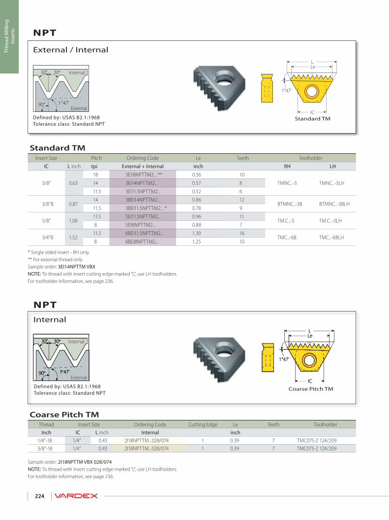
1°47’
LLe
IC
30° 30°
1 47'°90°
1°47’
LLe
IC
30° 30°
1 47'°90°
1°47’
LLe
IC
30° 30°
1 47'°90°
224
THre
ad M
illin
gIn
sert
s
Defined by: USAS B2.1:1968Tolerance class: Standard NPT
Coarse Pitch TM
Internal
NPT
External
Internal
Defined by: USAS B2.1:1968Tolerance class: Standard NPT
Standard TM
External / Internal
NPT
External
Internal
* Single sided insert - RH only ** For external thread onlySample order: 3EI14NPTTM VBX NOTE: To thread with insert cutting edge marked “L”, use LH toolholders.For toolholder information, see page 236.
Sample order: 2I18NPTTM VBX 028/074 NOTE: To thread with insert cutting edge marked “L”, use LH toolholders.For toolholder information, see page 236.
Standard TMInsert Size Pitch Ordering Code Le Teeth Toolholder
IC L inch tpi External + Internal inch RH LH
3/8” 0.63
18 3E18NPTTM2... ** 0.56 10
TMNC..-3 TMNC..-3LH14 3EI14NPTTM2... 0.57 8
11.5 3EI11.5NPTTM2... 0.52 6
3/8”B 0.8714 3BEI14NPTTM2... 0.86 12
BTMNC..-3B BTMNC..-3BLH11.5 3BEI11.5NPTTM2... * 0.78 9
5/8” 1.0611.5 5EI11.5NPTTM2... 0.96 11
TM.C..-5 TM.C..-5LH 8 5EI8NPTTM2... 0.88 7
3/4”B 1.5211.5 6BEI11.5NPTTM2... 1.39 16
TMC..-6B TMC..-6BLH 8 6BEI8NPTTM2... 1.25 10
Coarse Pitch TMThread Insert Size Ordering Code Cutting Edge Le Teeth Toolholder
Inch IC L inch Internal inch1/4"-18 1/4" 0.43 2I18NPTTM...028/074 1 0.39 7 TMC075-2 124/2093/8"-18 1/4" 0.43 2I18NPTTM...028/074 1 0.39 7 TMC075-2 124/209

30° 30°
1 47'°90°
1°47’
LLe
IC
1°47’
LLe
IC
30° 30°
1 47'°90°
225
THre
ad M
illin
gIn
sert
sDefined by: ANSI 1.20.3-1976Tolerance class: Standard NPTF
Coarse Pitch TM
Internal
NPTF (Dry Seal)
External
Internal
Defined by: ANSI 1.20.3-1976Tolerance class: Standard NPTF
Standard TM
External / Internal
NPTF (Dry Seal)
External
Internal
Sample order: 3EI14NPTFTM VBX NOTE: To thread with insert cutting edge marked “L”, use LH toolholders.For toolholder information, see page 236.
Sample tool requirement for thread 1/4” - 18NPTFOrdering Codes Insert: 2I18NPTFTM VBX 028/078 Toolholders: TMC075-2 124/209
Coarse Pitch TMThread Insert Size Ordering Code Cutting Edge Le Teeth Toolholder
Inch IC L inch Internal inch1/4"-18 1/4" 0.43 2I18NPTFTM...028/078 1 0.39 7 TMC075-2 124/2093/8"-18 1/4" 0.43 2I18NPTFTM...028/078 1 0.39 7 TMC075-2 124/209
Standard TMInsert Size Pitch Ordering Code Le Teeth Toolholder
IC L inch tpi External + Internal inch RH LH
3/8” 0.6314 3EI14NPTFTM2... 0.57 8
TMNC..-3 TMNC..-3LH11.5 3EI11.5NPTFTM2... 0.52 6
3/8”B 0.8714 3BEI14NPTFTM2... 0.86 12
BTMNC..-3B BTMNC..-3BLH11.5 3BEI11.5NPTFTM2... 0.78 9
5/8” 1.0611.5 5EI11.5NPTFTM2... 0.96 11
TM.C..-5 TM.C..-5LH8 5EI8NPTFTM2... 0.88 7
3/4”B 1.5211.5 6BEI11.5NPTFTM2... 1.39 16
TMC..-6B TMC..-6BLH8 6BEI8NPTFTM2... 1.25 10

30° 30°
LLe
IC
1°47’
LLe
IC
R0.137P27.5° 27.5°
90° 1 47'° R 0.137P
226
THre
ad M
illin
gIn
sert
s
Defined by: B.S. 21:1985Tolerance class: Standard BSPT
Standard TM
External / Internal
BSPT
External
Internal
Defined by: USA NBS H28 (1957)Tolerance class: Standard NPS
Standard TM
External / Internal
NPS
External
Internal
Sample Order: 5EI11.5NPSTM2VBXAll inserts have 2 cutting edges.For toolholder information, see page 236.* One cutting edge.
Sample Order: 5EI11BSPTTM VBX NOTE: To thread with insert cutting edge marked “L”, use a LH toolholder.For toolholder information, see page 236.
Standard TMInsert Size Pitch Ordering Code Le Teeth Nominal Thread Size Toolholder
IC L inch tpi External + Internal inch
3/8” 0.6314 3EI14NPSTM2... 0.57 8 1/2” TMNC0625-314 3EI14NPSTM2... 0.57 8 3/4” TMNC075-311.5 3EI11.5NPSTM2... 0.52 6 1”, 1 1/4” TMNC075-3
3/8”B 0.87 11.5 3BEI11.5NPSTM2...* 0.78 9 1”, 1 1/4” BTMNC075-3B
5/8” 1.0611.5 5EI11.5NPSTM2... 0.96 11 1 1/2”, 2” TMC100-5 8 5EI8NPSTM2... 0.88 7 2 1/2” & larger TMC125-5
Standard TMInsert Size Pitch Ordering Code Le Teeth Toolholder
IC L inch tpi External + Internal inch RH LH1/4” 0.43 19 2EI19BSPTTM2... 0.37 7 TMC..-2 TMC..-2LH
3/8” 0.6314 3EI14BSPTTM2... 0.57 8
TMNC..-3 TMNC..-3LH11 3EI11BSPTTM2... 0.55 6
5/8” 1.06 11 5EI11BSPTTM2... 0.91 10 TMC..-5 TMC..-5LH
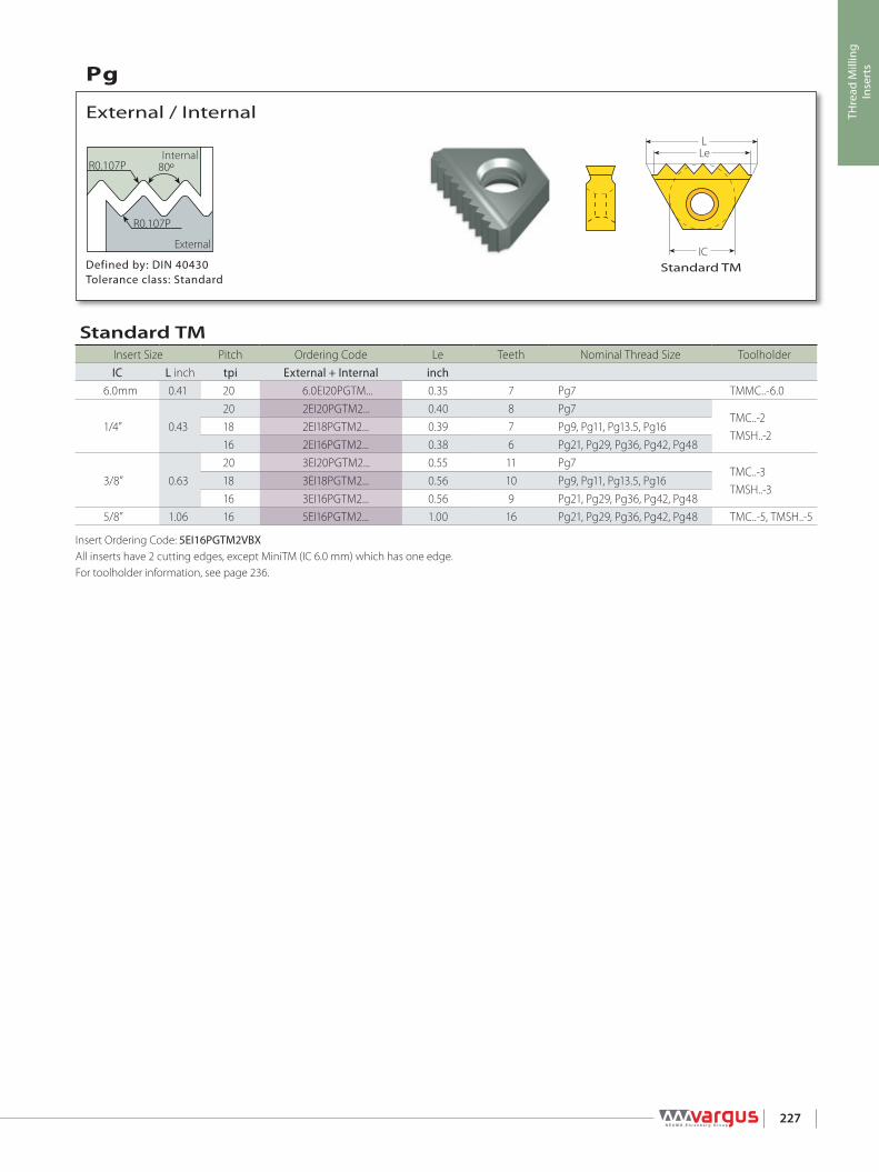
LLe
IC
R0.107P 80º
R0.107P
227
THre
ad M
illin
gIn
sert
s
Defined by: DIN 40430Tolerance class: Standard
Standard TM
External / Internal
Pg
External
Internal
Insert Ordering Code: 5EI16PGTM2VBX All inserts have 2 cutting edges, except MiniTM (IC 6.0 mm) which has one edge.For toolholder information, see page 236.
Standard TMInsert Size Pitch Ordering Code Le Teeth Nominal Thread Size ToolholderIC L inch tpi External + Internal inch
6.0mm 0.41 20 6.0EI20PGTM... 0.35 7 Pg7 TMMC..-6.0
1/4” 0.4320 2EI20PGTM2... 0.40 8 Pg7
TMC..-2TMSH..-2
18 2EI18PGTM2... 0.39 7 Pg9, Pg11, Pg13.5, Pg1616 2EI16PGTM2... 0.38 6 Pg21, Pg29, Pg36, Pg42, Pg48
3/8” 0.6320 3EI20PGTM2... 0.55 11 Pg7
TMC..-3TMSH..-3
18 3EI18PGTM2... 0.56 10 Pg9, Pg11, Pg13.5, Pg1616 3EI16PGTM2... 0.56 9 Pg21, Pg29, Pg36, Pg42, Pg48
5/8” 1.06 16 5EI16PGTM2... 1.00 16 Pg21, Pg29, Pg36, Pg42, Pg48 TMC..-5, TMSH..-5

LLe
IC
55°
R0.137P
R0.137P
228
THre
ad M
illin
gIn
sert
s
BSW Defined by: B.S.84:1956, DIN 259, ISO228/1:1982BSP Defined by: B.S.2779:1956Tolerance class: BSW-Medium class A, BSP-Medium class
Standard TM
External / Internal
W for BSW, BSP
External
Internal
Insert ordering code: 3EI14WTM2 VBXAll inserts have 2 cutting edges, except MiniTM (IC 6.0 mm) which has one cutting edge.For toolholder information, see page 236.
Standard TMInsert Size Pitch Ordering Code Le Teeth
IC L inch tpi External + Internal inch Toolholder
6.0mm 0.41
28 6.0EI28WTM... 0.36 10
TMMC..-6.026 6.0EI26WTM... 0.35 924 6.0EI24WTM... 0.38 920 6.0EI20WTM... 0.35 719 6.0EI19WTM... 0.37 7
1/4” 0.43
28 2EI28WTM2... 0.39 11
TMC..-2TMSH..-2
26 2EI26WTM2... 0.38 1024 2EI24WTM2... 0.38 920 2EI20WTM2... 0.40 819 2EI19WTM2... 0.37 714 2EI14WTM2... 0.36 5
3/8” 0.63
26 3EI26WTM2... 0.58 15
TMC..-3TMSH..-3
24 3EI24WTM2... 0.58 1420 3EI20WTM2... 0.55 1119 3EI19WTM2... 0.58 1118 3EI18WTM2... 0.56 1016 3EI16WTM2... 0.56 914 3EI14WTM2... 0.57 812 3EI12WTM2... 0.58 711 3EI11WTM2... 0.55 6
3/8”B 0.87
24 3BEI24WTM2... 0.83 20
TMC..-3BTMSH..-3B
20 3BEI20WTM2... 0.85 1719 3BEI19WTM2... 0.84 1618 3BEI18WTM2... 0.83 1516 3BEI16WTM2... 0.81 1314 3BEI14WTM2... 0.86 1212 3BEI12WTM2... 0.83 1011 3BEI11WTM2... 0.82 9
5/8” 1.06
16 5EI16WTM2... 1.00 16
TMC..-5TMSH..-5
14 5EI14WTM2... 1.00 1412 5EI12WTM2... 0.92 1111 5EI11WTM2... 0.91 1010 5EI10WTM2... 1.00 109 5EI9WTM2... 0.89 88 5EI8WTM2... 0.88 77 5EI7WTM2... 0.86 66 5EI6WTM2... 0.83 5
3/4”B 1.52
11 6BEI11WTM2... 1.36 15TMC..-6BTMSH..-6B
6 6BEI6WTM2... 1.33 85 6BEI5WTM2... 1.20 64.5 6BEI4.5WTM2... 1.33 6
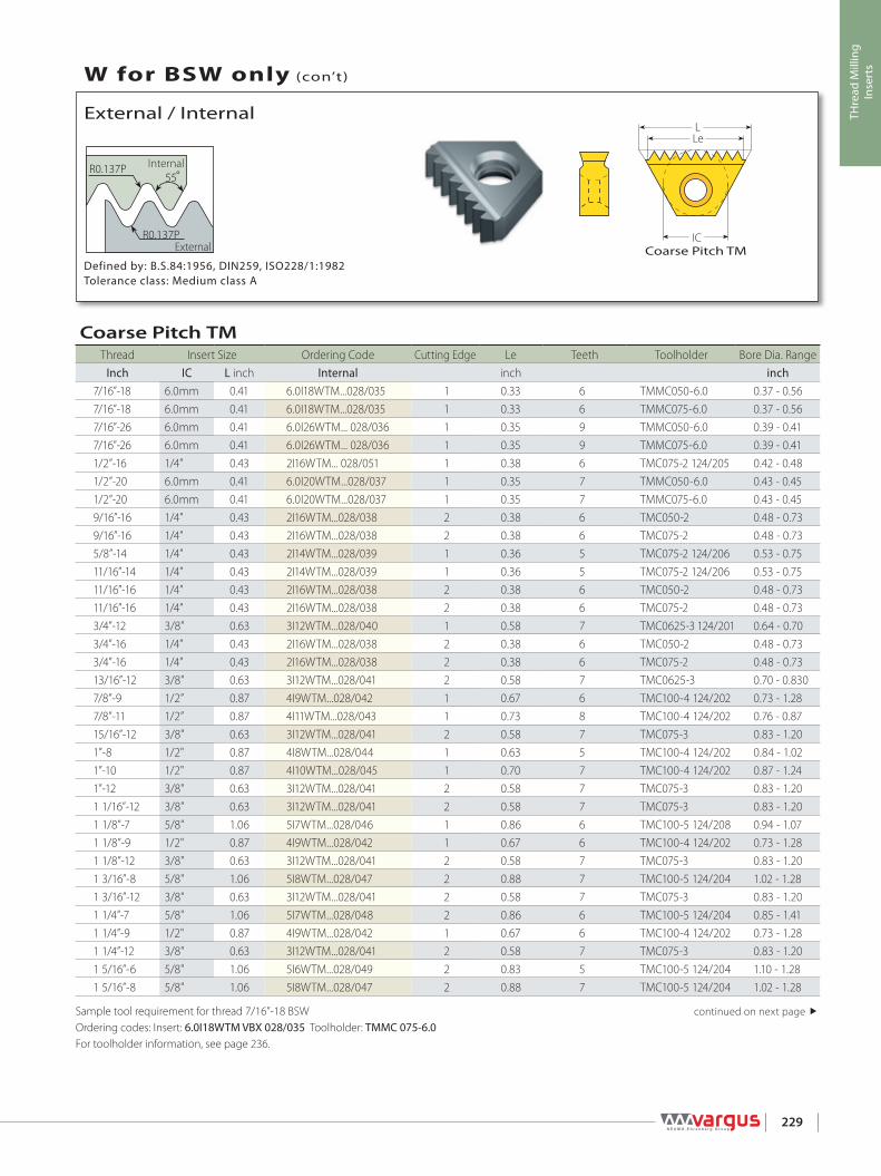
LLe
ICExtern
Intern55°
R0.137P
R0.137P
229
THre
ad M
illin
gIn
sert
s
Defined by: B.S.84:1956, DIN259, ISO228/1:1982Tolerance class: Medium class A
Coarse Pitch TM
External / Internal
W for BSW only (con’t)
External
Internal
Sample tool requirement for thread 7/16”-18 BSW Ordering codes: Insert: 6.0I18WTM VBX 028/035 Toolholder: TMMC 075-6.0 For toolholder information, see page 236.
Coarse Pitch TMThread Insert Size Ordering Code Cutting Edge Le Teeth Toolholder Bore Dia. Range
Inch IC L inch Internal inch inch7/16”-18 6.0mm 0.41 6.0I18WTM...028/035 1 0.33 6 TMMC050-6.0 0.37 - 0.567/16”-18 6.0mm 0.41 6.0I18WTM...028/035 1 0.33 6 TMMC075-6.0 0.37 - 0.567/16”-26 6.0mm 0.41 6.0I26WTM... 028/036 1 0.35 9 TMMC050-6.0 0.39 - 0.417/16”-26 6.0mm 0.41 6.0I26WTM... 028/036 1 0.35 9 TMMC075-6.0 0.39 - 0.411/2”-16 1/4” 0.43 2I16WTM... 028/051 1 0.38 6 TMC075-2 124/205 0.42 - 0.481/2”-20 6.0mm 0.41 6.0I20WTM...028/037 1 0.35 7 TMMC050-6.0 0.43 - 0.451/2”-20 6.0mm 0.41 6.0I20WTM...028/037 1 0.35 7 TMMC075-6.0 0.43 - 0.459/16”-16 1/4” 0.43 2I16WTM...028/038 2 0.38 6 TMC050-2 0.48 - 0.739/16”-16 1/4” 0.43 2I16WTM...028/038 2 0.38 6 TMC075-2 0.48 - 0.735/8”-14 1/4” 0.43 2I14WTM...028/039 1 0.36 5 TMC075-2 124/206 0.53 - 0.7511/16”-14 1/4” 0.43 2I14WTM...028/039 1 0.36 5 TMC075-2 124/206 0.53 - 0.7511/16”-16 1/4” 0.43 2I16WTM...028/038 2 0.38 6 TMC050-2 0.48 - 0.7311/16”-16 1/4” 0.43 2I16WTM...028/038 2 0.38 6 TMC075-2 0.48 - 0.733/4”-12 3/8" 0.63 3I12WTM...028/040 1 0.58 7 TMC0625-3 124/201 0.64 - 0.703/4”-16 1/4” 0.43 2I16WTM...028/038 2 0.38 6 TMC050-2 0.48 - 0.733/4”-16 1/4” 0.43 2I16WTM...028/038 2 0.38 6 TMC075-2 0.48 - 0.7313/16”-12 3/8" 0.63 3I12WTM...028/041 2 0.58 7 TMC0625-3 0.70 - 0.8307/8”-9 1/2” 0.87 4I9WTM...028/042 1 0.67 6 TMC100-4 124/202 0.73 - 1.287/8”-11 1/2” 0.87 4I11WTM...028/043 1 0.73 8 TMC100-4 124/202 0.76 - 0.8715/16”-12 3/8" 0.63 3I12WTM...028/041 2 0.58 7 TMC075-3 0.83 - 1.201”-8 1/2" 0.87 4I8WTM...028/044 1 0.63 5 TMC100-4 124/202 0.84 - 1.021”-10 1/2" 0.87 4I10WTM...028/045 1 0.70 7 TMC100-4 124/202 0.87 - 1.241”-12 3/8" 0.63 3I12WTM...028/041 2 0.58 7 TMC075-3 0.83 - 1.201 1/16”-12 3/8" 0.63 3I12WTM...028/041 2 0.58 7 TMC075-3 0.83 - 1.201 1/8”-7 5/8" 1.06 5I7WTM...028/046 1 0.86 6 TMC100-5 124/208 0.94 - 1.071 1/8”-9 1/2" 0.87 4I9WTM...028/042 1 0.67 6 TMC100-4 124/202 0.73 - 1.281 1/8”-12 3/8" 0.63 3I12WTM...028/041 2 0.58 7 TMC075-3 0.83 - 1.201 3/16”-8 5/8" 1.06 5I8WTM...028/047 2 0.88 7 TMC100-5 124/204 1.02 - 1.281 3/16”-12 3/8" 0.63 3I12WTM...028/041 2 0.58 7 TMC075-3 0.83 - 1.201 1/4”-7 5/8" 1.06 5I7WTM...028/048 2 0.86 6 TMC100-5 124/204 0.85 - 1.411 1/4”-9 1/2" 0.87 4I9WTM...028/042 1 0.67 6 TMC100-4 124/202 0.73 - 1.281 1/4”-12 3/8" 0.63 3I12WTM...028/041 2 0.58 7 TMC075-3 0.83 - 1.201 5/16”-6 5/8" 1.06 5I6WTM...028/049 2 0.83 5 TMC100-5 124/204 1.10 - 1.281 5/16”-8 5/8" 1.06 5I8WTM...028/047 2 0.88 7 TMC100-5 124/204 1.02 - 1.28
continued on next page

LLe
IC
55°
R0.137P
R0.137P
230
THre
ad M
illin
gIn
sert
s
Defined by: B.S.84:1956, DIN259, ISO228/1:1982Tolerance class: Medium class A
Coarse Pitch TM Inserts
Internal
W for BSW only (con’t)
External
Internal
Sample tool requirement for thread 1 5/16”-12 BSWOrdering codes: Insert: 3I12WTM VBX 028/041 Toolholder: TMC 075-3For toolholder information, see page 236.
Coarse Pitch TMThread Insert Size Ordering Code Cutting Edge Le Teeth Tooolholder Bore Dia. Range
IC L inch Internal inch inch1 5/16”-12 3/8" 0.63 3I12WTM...028/041 2 0.58 7 TMC075-3 0.83 - 1.201 3/8”-8 5/8" 1.06 5I8WTM...028/047 2 0.88 7 TMC100-5 124/204 1.02 - 1.281 3/8”-6 5/8" 1.06 5I6WTM...028/049 2 0.83 5 TMC100-5 124/204 1.10 - 1.281 3/8”-12 5/8" 1.06 5I12WTM...028/050 2 0.92 11 TMC100-5 1.27 - 1.361.4-6 5/8 " 1.06 5I6WTM...028/049 2 0.83 5 TMC100-5 124/204 1.10 - 1.281.4-8 5/8" 1.06 5I8WTM...028/047 2 0.88 7 TMC100-5124/204 1.02 - 1.281.4-12 5/8" 1.06 5I12WTM...028/050 2 0.92 11 TMC100-5 1.27 - 1.361 7/16”-6 5/8" 1.06 5I6WTM...028/049 2 0.83 5 TMC100-5 124/204 1.10 - 1.281 7/16”-8 5/8" 1.06 5I8WTM...028/047 2 0.88 7 TMC100-5 1.28 - 1.541 7/16”-12 5/8" 1.06 5I12WTM...028/050 2 0.92 11 TMC100-5 1.27 - 1.361 1/2”-6 5/8" 1.06 5I6WTM...028/049 2 0.83 5 TMC100-5 124/204 1.10 - 1.291 1/2” -8 5/8" 1.06 5I8WTM...028/047 2 0.88 7 TMC100-5 1.28 - 1.541.6-6 5/8" 1.06 5I6WTM...028/049 2 0.83 5 TMC100-5 1.28 - 1.521.6-8 5/8" 1.06 5I8WTM...028/047 2 0.88 7 TMC100-5 1.28 - 1.541 5/8”-8 5/8" 1.06 5I8WTM...028/047 2 0.88 7 TMC100-5 1.28 - 1.541 5/8”-6 5/8" 1.06 5I6WTM...028/049 2 0.83 5 TMC100-5 1.28 - 1.521 3/4”-7 5/8" 1.06 5I7WTM...028/048 2 0.86 6 TMC100-5 1.57 - 1.651 7/8”-6 5/8" 1.06 5I6 WTM...028/049 2 0.83 5 TMC125-5 1.66 - 1.771.9-6 5/8" 1.06 5I6 WTM...028/049 2 0.83 5 TMC125-5 1.66 - 1.77

LLe
IC
55°
R0.137P
R0.137P
ECL
231
THre
ad M
illin
gIn
sert
s
ECL - The Effective Cutting Length
BSW Defined by: B.S.84:1956, DIN 259, ISO228/1:1982BSP Defined by: B.S.2779:1956Tolerance class: BSW-Medium class A
Standard TM
External / Internal
W for BSW only (con’t)
External
Internal
Sample order: 3EI19WTM2 VBXFor Le and number of teeth of the above inserts, see the table for standard inserts on page 228.For toolholder information see page 236.
Standard TM Inserts for TMO ToolholdersInsert Size Pitch Ordering Code ECL
IC L inch tpi External + Internal TMO inch
1/4” 0.43
28 2EI28WTM2... TMOC075-2-3 0.6826 2EI26WTM2... TMOC075-2-5 0.7324 2EI24WTM2... TMOC075-2-2 0.7120 2EI20WTM2... TMOC075-2-6 0.7519 2EI19WTM2... TMOC075-2-7 0.6814 2EI14WTM2... TMOC075-2-3 0.64
3/8” 0.63
26 3EI26WTM2... TMOC075-3-2 1.0826 3EI26WTM2... TMOC075-3-6 1.0424 3EI24WTM2... TMOC075-3-7 1.1220 3EI20WTM2... TMOC075-3-6 1.0519 3EI19WTM2... TMOC075-3-8 1.1118 3EI18WTM2... TMOC075-3-6 1.0616 3EI16WTM2... TMOC075-3-6 1.0614 3EI14WTM2... TMOC075-3-6 1.0712 3EI12WTM2... TMOC075-3-6 1.0811 3EI11WTM2... TMOC075-3-9 1.09
5/8” 1.06
16 5EI16WTM2... TMOC100-5-3 1.8814 5EI14WTM2... TMOC100-5-1 2.0014 5EI14WTM2... TMOC100-5-4 1.8612 5EI12WTM2... TMOC100-5-2 1.7511 5EI11WTM2... TMOC100-5-6 1.8210 5EI10WTM2... TMOC100-5-7 1.809 5EI9WTM2... TMOC100-5-8 1.788 5EI8WTM2... TMOC100-5-9 1.757 5EI7WTM2... TMOC100-5-4 1.716 5EI6WTM2... TMOC100-5-11 1.67

LLe
IC
29°
232
THre
ad M
illin
gIn
sert
s
Defined by: ANSI B1/5:1988Tolerance class: 3G Coarse Pitch TM
Internal
ACME
External
Internal
Sample tool requirement for thread ACME 1 3/4”-5Ordering Code: Insert: 5I5ACME VBX 028/071 Toolholder: TMC100-5 124/204 For toolholder information, see page 236.
Coarse Pitch TMThread Insert Size Ordering Code Cutting Edge Le Teeth Toolholder Bore Dia. Range
Inch IC L inch Internal inch inch1/2”-16 6.0mm 0.41 6.0I16ACMETM...028/052 1 0.31 5 TMMC050-6.0 0.441/2”-16 6.0mm 0.41 6.0I16ACMETM...028/052 1 0.31 5 TMMC075-6.0 0.445/8”-16 1/4" 0.43 2I16ACMETM...028/053 2 0.38 6 TMC050-2 0.565/8"-16 1/4" 0.43 2I16ACMETM...028/053 2 0.38 6 TMC075-2 0.565/8"-14 1/4" 0.43 2I14ACMETM...028/054 1 0.36 5 TMC075-2 124/205 0.553/4”-16 1/4" 0.43 2I16ACMETM...028/055 2 0.38 6 TMC050-2 0.693/4”-16 1/4" 0.43 2I16ACMETM...028/055 2 0.38 6 TMC075-2 0.693/4”-14 1/4" 0.43 2I14ACMETM...028/083 1 0.36 5 TMC075-2 124/206 0.683/4”-12 1/4" 0.43 2I12ACMETM...028/056 1 0.33 4 TMC075-2 124/206 0.677/8”-14 3/8" 0.63 3I14ACMETM...028/057 2 0.57 8 TMNC0625-3 0.807/8”-12 1/4" 0.43 2I12ACMETM...028/058 1 0.33 4 TMC075-2 124/206 0.791”-14 3/8" 0.63 3I14ACMETM...028/059 2 0.57 8 TMC0625-3 0.931”-12 3/8" 0.63 3I12ACMETM...028/060 2 0.58 7 TMNC0625-3 0.911”-10 1/2" 0.87 4I10ACMETM...028/061 1 0.70 7 TMC100-4 124/202 0.901”-8 1/2" 0.87 4I8ACMETM...028/062 1 0.75 6 TMC100-4 124/202 0.871 1/8”-12 3/8" 0.63 3I12ACMETM...028/060 2 0.58 7 TMC0625-3 1.041 1/8”-10 1/2" 0.87 4I10ACMETM...028/084 1 0.70 7 TMC100-4 124/207 1.021 1/8”-8 1/2" 0.87 4I8ACMETM...028/063 1 0.75 6 TMC100-4 124/202 1.00 - 1.121 1/4”-12 3/8" 0.63 3I12ACMETM...028/060 2 0.58 7 TMC075-3 1.171 1/4”-10 5/8" 1.06 5I10ACMETM....028/064 2 0.90 9 TMC100-5 124/204 1.151 1/4”-8 1/2" 0.87 4I8ACMETM...028/063 1 0.75 6 TMC100-4 124/202 1.00 - 1.121 3/8”-10 5/8" 1.06 5I10ACMETM...028/065 2 0.90 9 TMC100-5 124/204 1.271 3/8”-8 5/8" 1.06 5I8ACMETM...028/066 2 0.88 7 TMC100-5 124/204 1.251 3/8”-6 5/8" 1.06 5I6ACMETM...028/067 1 0.83 5 TMC100-5 124/208 1.201 1/2”-10 5/8" 1.06 5I10ACMETM...028/068 2 0.90 9 TMC100-5 1.401 1/2”-8 5/8" 1.06 5I8ACMETM...028/069 2 0.88 7 TMC100-5 124/204 1.371 1/2”-6 5/8" 1.06 5I6ACMETM...028/070 2 0.83 5 TMC100-5 124/204 1.331 3/4”-10 5/8" 1.06 5I10ACMETM...028/064 2 0.90 9 TMC125-5 1.651 3/4”-8 5/8" 1.06 5I8ACMETM...028/069 2 0.88 7 TMC100-5 1.621 3/4”-6 5/8" 1.06 5I6ACMETM...028/070 2 0.83 5 TMC100-5 1.581 3/4”-5 5/8" 1.06 5I5ACMETM...028/071 2 0.80 4 TMC100-5 124/204 1.552”-8 5/8" 1.06 5I8ACMETM...028/069 2 0.88 7 TMC125-5 1.872”-6 5/8" 1.06 5I6ACMETM...028/072 2 0.83 5 TMC100-5 1.832”-5 5/8" 1.06 5I5ACMETM...028/071 2 0.80 4 TMC100-5 1.802 1/4”-6 5/8" 1.06 5I6ACMETM...028/072 2 0.83 5 TMC125-5 2.082 1/4”-5 5/8" 1.06 5I5ACMETM...028/073 2 0.80 4 TMC100-5 2.052 1/2”-5 5/8" 1.06 5I5ACMETM...028/073 2 0.80 4 TMC125-5 2.30

30°
LLe
IC
233
THre
ad M
illin
gIn
sert
s
Defined by: Trapez DIN 103Tolerance class: 7e/7H
Coarse Pitch TM
Internal
TR
External
Internal
Sample tool requirement for thread TR 38x3.0Ordering Code: Insert: 5I3.0TRTM VBX 028/033 Toolholder: TMC100-5 124/204 For toolholder information, see page 236.
Coarse Pitch TMThread Insert Size Ordering Code Cutting Edge Le Teeth Toolholder Bore Dia. Range
mm IC L inch Internal inch inchTR 16X2.0 1/4" 0.43 2I2.0TRTM...028/028 1 0.39 5 TMC075-2 124/206 0.55TR 18X2.0 1/4" 0.43 2I2.0TRTM...028/029 1 0.39 5 TMC075-2 124/206 0.63 - 0.71TR 20X2.0 1/4" 0.43 2I2.0TRTM...028/029 1 0.39 5 TMC075-2 124/206 0.63 - 0.71TR 24X3.0 1/2" 0.87 4I3.0TRTM...028/030 1 0.71 6 TMC100-4 124/202 0.83TR 26X3.0 1/2" 0.87 4I3.0TRTM...028/031 1 0.71 6 TMC100-4 124/202 0.91 - 1.06TR 28X3.0 1/2" 0.87 4I3.0TRTM...028/031 1 0.71 6 TMC100-4 124/202 0.91 - 1.06TR 30X3.0 1/2" 0.87 4I3.0TRTM...028/031 1 0.71 6 TMC100-4 124/202 0.91 - 1.06TR 32X3.0 1/2" 0.87 4I3.0TRTM...028/032 1 0.71 6 TMC100-4 124/207 1.14 - 1.30TR 34X3.0 1/2" 0.87 4I3.0TRTM...028/032 1 0.71 6 TMC100-4 124/207 1.14 - 1.30TR 36X3.0 1/2" 0.87 4I3.0TRTM...028/032 1 0.71 6 TMC100-4 124/207 1.14 - 1.30TR 38X3.0 5/8" 1.06 5I3.0TRTM...028/033 2 0.94 8 TMC100-5 124/204 1.38 - 1.54TR 40X3.0 5/8" 1.06 5I3.0TRTM...028/033 2 0.94 8 TMC100-5 124/204 1.38 - 1.54TR 42X3.0 5/8" 1.06 5I3.0TRTM...028/033 2 0.94 8 TMC100-5 124/204 1.38 - 1.54TR 44X3.0 5/8" 1.06 5I3.0TRTM...028/033 2 0.94 8 TMC100-5 1.61 - 1.77TR 46X3.0 5/8" 1.06 5I3.0TRTM...028/033 2 0.94 8 TMC100-5 1.61 - 1.77TR 48X3.0 5/8" 1.06 5I3.0TRTM...028/033 2 0.94 8 TMC100-5 1.61 - 1.77TR 50X3.0 5/8" 1.06 5I3.0TRTM...028/033 2 0.94 8 TMC125-5 1.85 - 2.24TR 52X3.0 5/8" 1.06 5I3.0TRTM...028/033 2 0.94 8 TMC125-5 1.85 - 2.24TR 55X3.0 5/8" 1.06 5I3.0TRTM...028/033 2 0.94 8 TMC125-5 1.85 - 2.24TR 60X3.0 5/8" 1.06 5I3.0TRTM...028/033 2 0.94 8 TMC125-5 1.85 - 2.24TR 65X4.0 5/8" 1.06 5I4.0TRTM...028/034 2 0.94 6 TMC125-5 2.40 - 4.17TR 70X4.0 5/8" 1.06 5I4.0TRTM...028/034 2 0.94 6 TMC125-5 2.40 - 4.17TR 75X4.0 5/8" 1.06 5I4.0TRTM...028/034 2 0.94 6 TMC125-5 2.40 - 4.17TR 80X4.0 5/8" 1.06 5I4.0TRTM...028/034 2 0.94 6 TMC125-5 2.40 - 4.17TR 85X4.0 5/8" 1.06 5I4.0TRTM...028/034 2 0.94 6 TMC125-5 2.40- 4.17TR 90X4.0 5/8" 1.06 5I4.0TRTM...028/034 2 0.94 6 TMC125-5 2.40 - 4.17TR 95X4.0 5/8" 1.06 5I4.0TRTM...028/034 2 0.94 6 TMC125-5 2.40 - 4.17TR 100X4.0 5/8" 1.06 5I4.0TRTM...028/034 2 0.94 6 TMC125-5 2.40 - 4.17TR 105X4.0 5/8" 1.06 5I4.0TRTM...028/034 2 0.94 6 TMC125-5 2.40 - 4.17TR 110X4.0 5/8" 1.06 5I4.0TRTM...028/034 2 0.94 6 TMC125-5 2.40 - 4.17

234
THre
ad M
illin
gIn
sert
s

Thread Milling> Standard Toolholders

236
THre
ad M
illin
gTo
olho
lder
s
Thread Milling Shell Mill
Vardex Ordering Code SystemThread Milling Toolholders
THREAD MILLING TOOLHOLDERS
VARDEX Ordering Code System ...............................................................................................................................................Page 236
Standard Toolholder TM ................................................................................................................................................................Page 237
Long Shank Toolholder TML .......................................................................................................................................................Page 238
Coarse Pitch Toolholder 124/... ................................................................................................................................................Page 239
Taper Thread (NPT, NPTF, BSPT) Toolholder TMN ...........................................................................................................Page 239
Twin Flute Toolholder TM2 ..........................................................................................................................................................Page 240
Twin Flute Offset Toolholder TMO ..........................................................................................................................................Page 241
Standard Single Point TM Toolholder TMS.........................................................................................................................Page 242
Vertical Insert TM Toolholder TMV ..........................................................................................................................................Page 242
TM Shell Mill .........................................................................................................................................................................................Page 243
Spare Parts For VARDEX TM and TMSH Toolholders .............................................................................................Page 244
5 - Cut. Edge LengthB - TMB
4 - Insert Size
2 - 1/4”3 - 3/8”3B - 3/8”B5 - 5/8”6B - 3/4”B
3 - Drive Hole Dia. 1/2, 3/4, 1, 1 1/4, 1 1/2
2 - Cutting Dia.150, 200, 250, 300, 400, 500
1 - SystemThread Mill Shell Mill
B5
34
-0753
-D2502
-TMSH1
6 - Insert Size
6.0 - 6.0mm2 - 1/4”3 - 3/8”3B - 3/8”B4 - 1/2”5 - 5/8”6B - 3/4”B
11 - Serial No.
(for Coarse Pitch holders)124/...
8 - Serial No.
(for TMO Holders) 1 - 16
9 - Shank std.
None - WeldonCW - Clarkson Weldon
10 - RH / LH Holder
None - Right HandLH - Left Hand
7 - Cut. Edge LengthB - TMB
5 - Shank Dia.0375 - 3/8"050 - 1/2"0625 - 5/8"075 - 3/4"100 - 1"125 - 1 1/4"
4 - CoolingC - Coolant Channel
3 - Holder Type
2 - Twin FluteM - MiniL - Long ToolN - Tapered Holder
V - Vertical HolderS - Single PointO - OffsetW - Wide Cut. Dia.
2 - SystemTM - Thread Milling
1 - Shank TypeB - Anti Vibration System
LH10 11
CW98
B7
36
-0.755
C4
N3
TM2
B1
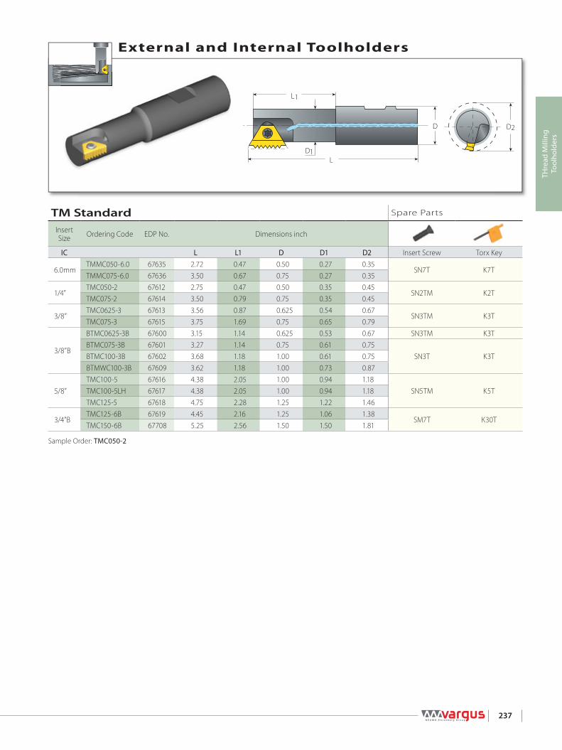
D2D
D1
L1
L
237
THre
ad M
illin
gTo
olho
lder
s
External and Internal Toolholders
Sample Order: TMC050-2
TM Standard Spare Parts
Insert Size Ordering Code EDP No. Dimensions inch
IC L L1 D D1 D2 Insert Screw Torx Key
6.0mmTMMC050-6.0 67635 2.72 0.47 0.50 0.27 0.35
SN7T K7TTMMC075-6.0 67636 3.50 0.67 0.75 0.27 0.35
1/4”TMC050-2 67612 2.75 0.47 0.50 0.35 0.45
SN2TM K2TTMC075-2 67614 3.50 0.79 0.75 0.35 0.45
3/8”TMC0625-3 67613 3.56 0.87 0.625 0.54 0.67
SN3TM K3TTMC075-3 67615 3.75 1.69 0.75 0.65 0.79
3/8”B
BTMC0625-3B 67600 3.15 1.14 0.625 0.53 0.67 SN3TM K3TBTMC075-3B 67601 3.27 1.14 0.75 0.61 0.75
SN3T K3TBTMC100-3B 67602 3.68 1.18 1.00 0.61 0.75BTMWC100-3B 67609 3.62 1.18 1.00 0.73 0.87
5/8”TMC100-5 67616 4.38 2.05 1.00 0.94 1.18
SN5TM K5TTMC100-5LH 67617 4.38 2.05 1.00 0.94 1.18TMC125-5 67618 4.75 2.28 1.25 1.22 1.46
3/4”BTMC125-6B 67619 4.45 2.16 1.25 1.06 1.38
SM7T K30TTMC150-6B 67708 5.25 2.56 1.50 1.50 1.81

D
D1
L1
L
D2
238
THre
ad M
illin
gTo
olho
lder
s
External and Internal Toolholders
TML Long Tools Spare Parts
Insert Size Ordering Code EDP No. Dimensions
inch
IC L L1 D D1 D2 Insert Screw Torx Key1/4” TMLC100-2 67719 4.95 0.67 1.00 0.35 0.45 SN2TM K2T
3/8”TMLC100-3 67624 5.00 0.98 1.00 0.73 0.87
SN3T K3TBTMLC100-3 67737 4.95 2.50 1.00 0.73 0.87
3/8”BBTMLC075-3B 67603 3.86 1.73 0.75 0.61 0.75
SN3T K3TBTMLC100-3B 67604 4.95 2.50 1.00 0.73 0.87
5/8”TMLC100-5 67625 5.88 3.62 1.00 0.94 1.18
SN5TM K5TTMLC125-5 67628 6.33 3.86 1.25 1.22 1.46
3/4”B TMLC150-6B 67720 6.55 3.74 1.50 1.50 1.81 SM7T K30TSample Order: TMLC100-3

D
D1
L1
L
D2
D2D
D1
L1
L
A A
LH Tool RH Tool
L R
239
THre
ad M
illin
gTo
olho
lder
s
External and Internal Toolholders
External and Internal Toolholders
Sample Order: TMMC 075-6 124/203
Sample Order: TMNC075-3NOTE: To use the cutting edge marked “L“, LH Cutter is required. Add LH to the ordering code.
TMN - For Conical Threads (NPT, NPTF, BSPT) Spare Parts
Insert Size
Ordering Code EDPNo.
EDPNo. Dimensions inch
IC RH LH L L1 D D1 D2 Insert Screw Torx Key
3/8”TMNC0625-3 67638 TMNC0625-3 LH 67639 3.56 0.87 0.625 0.49 0.61
SN3TM K3TTMNC075-3 67640 TMNC075-3 LH 67641 3.38 0.91 0.75 0.59 0.75
3/8”BBTMNC0625-3B 67605 BTMNC0625-3B LH 67606 3.15 1.14 0.625 0.53 0.67
SN3TM K3TBTMNC075-3B 67607 BTMNC075-3B LH 67730 3.27 1.14 0.75 0.61 0.75
5/8” TMNC125-5 67644 TMNC125-5 LH 67645 4.75 2.28 1.25 1.22 1.46 SN5TM K5T
124/.. - For Coarse Pitch Threads Spare Parts
Insert Size Ordering Code EDP No. Dimensions inch
IC L L1 D D1 D2 Insert Screw Torx Key6.0mm TMMC075-6 124/203 67700 3.50 0.59 0.75 0.26 0.35 SN7T K7T
1/4”TMC075-2 124/205 67702 3.12 0.61 0.75 0.29 0.39
SN2TM K2TTMC075-2 124/206 67703 3.12 0.61 0.75 0.35 0.47TMC075-2 124/209 67706 3.12 0.61 0.75 0.29 0.39
3/8” TMC0625-3 124/201 67698 3.75 0.81 0.75 0.48 0.61 SN3TM K3T
1/2”TMC100-4 124/202 67699 3.58 1.18 1.00 0.53 0.71 SN4TM
K4TTMC100-4 124/207 67704 3.97 1.57 1.00 0.63 0.79 SA4TM
5/8”TMC100-5 124/204 67701 3.98 1.57 1.00 0.75 0.98 SA5TM
K5TTMC100-5 124/208 67705 3.98 1.57 1.00 0.65 0.87 SN5TM

D2D
D1
L1
L
240
THre
ad M
illin
gTo
olho
lder
s
External and Internal Toolholders
Sample Order: TM2C125-5
TM2 - Twin Flutes Spare Parts
Insert Size Ordering Code EPD No. Dimensions inch
IC L L1 D D1 D2 Insert Screw Torx Key1/4” TM2C075-2 67685 3.42 0.79 0.75 0.57 0.67 SN2TM K2T3/8” TM2C100-3 67686 4.02 1.69 1.00 0.89 1.02
SN3T K3T3/8”B BTM2C100-3B 67718 4.13 1.81 1.00 0.89 1.025/8” TM2C125-5 67687 4.65 1.77 1.25 1.42 1.65 SN5TM K5T3/4”B TM2C150-6B 67688 5.33 2.56 1.50 1.73 2.05 SM7T K30T

D2D
D1
L1
L
241
THre
ad M
illin
gTo
olho
lder
s
External and Internal Toolholders
Sample Order: TMOC075-3-7
TMO - Twin Flute Offset Spare Parts
InsertSize
Ordering Code EDP No. Applicable Threads Dimensions inch
IC External Internal External & Internal L L1 D D1 D2 Insert Screw Torx Key
1/4”
TMOC075-2-1 67655 16UN 48/32/16UN
3.50 0.98 0.75 0.47 0.57 SN2TM K2T
TMOC075-2-2 67657 24/18UN 48/24/18UN 24WTMOC075-2-3 67658 28/14UN 28/14UN 28/14WTMOC075-2-4 67659 20UN 20UNTMOC075-2-5 67693 26WTMOC075-2-6 67727 20WTMOC075-2-7 67660 19WTMOC075-2-8 67713 1.0/1.5ISO 0.5/1.0/1.5ISOTMOC075-2-9 67762 0.75ISO 48UN, 0.75ISOTMOC075-2-10 67656 1.25ISO 1.25ISO
3/8”
TMOC075-3-1 67661 1.5ISO 0.5/1.5ISO
3.75 1.69 0.75 0.65 0.79 SN3T K3T
TMOC075-3-2 67763 13UN 13UN 26WTMOC075-3-3 67663 28UN 32/28UNTMOC075-3-4 67674 27UN 27UNTMOC075-3-5 67664 11.5UN 11.5NPSTMOC075-3-6 67665 24/20/18/16/14/12UN 24/20/18/16/14/12UN 26/20/18/16/14/12W, 14NPSTMOC075-3-7 67764 1.25ISO 1.25ISO 24WTMOC075-3-8 67765 19WTMOC075-3-9 67716 11WTMOC075-3-10 67662 1.0/2.0ISO 0.5/1.0/2.0ISOTMOC075-3-11 67766 0.75ISO 32UN, 0.75ISOTMOC075-3-12 67767 1.75ISO 1.75ISO
5/8”
TMOC100-5-1 67666 24/20/18/14/13/12UN 24/20/18/14/13/11UN 14W
4.38 2.05 1.00 0.94 1.18 SN5TM K5T
TMOC100-5-2 67667 24/18/12UN 24/18/12/6UN 12WTMOC100-5-3 67668 16UN 16UN 16W, 8NPSTMOC100-5-4 67669 14/7UN 14UN 14/7WTMOC100-5-5 67726 11.5UN 11.5NPSTMOC100-5-6 67707 11UN 11UN 11WTMOC100-5-7 67670 10UN 10/5UN 10WTMOC100-5-8 67714 9UN 9UN 9WTMOC100-5-9 67671 8UN 8UN 8WTMOC100-5-10 67678 7UNTMOC100-5-11 67768 6UN 6WTMOC100-5-12 67712 1.0/2.0/2.5/4.0ISO 1.0/2.0/2.5/4.0/5.0ISOTMOC100-5-13 67769 1.25ISO 1.25ISOTMOC100-5-14 67770 1.5/2.5/4.5ISO 1.5/2.5/4.5/ISOTMOC100-5-15 67771 1.75ISO 1.75ISOTMOC100-5-16 67760 1.0/1.5/3.0/3.5ISO 1.0/1.5/3.0/3.5ISO

D2D
D1
L1
L
D
D1
L1
LT
D2
242
THre
ad M
illin
gTo
olho
lder
s
External and Internal Toolholders
External and Internal Toolholders
Sample Order: TMSC0375-2NOTE: Use Standard laydown thread turning inserts. See Thread Turning Inserts section - Page 17.Use external LH inserts for external thread and internal RH inserts for internal thread.
Sample Order: TMVC125-5NOTE: Requires IC 5/8” vertical thread turning inserts (width T=6). Use external LH inserts for external threads and internal RH inserts for internal threads. See Thread Turning Inserts section - Page 17.
TMV - Single Point (Vertical Insert) Spare Parts
Insert Size Ordering Code EDP No. Dimensions inch
IC L L1 D D1 D2 Insert Screw Torx Key5/8”V TMVC125-5 67677 4.65 2.36 1.25 1.40 1.81 SN6T K6T
TMS - Single Point (Standard Inserts) Spare Parts
Insert Size Ordering Code EDP No. Dimensions inch
IC L L1 D D1 D2 Insert Screw Torx Key1/4” TMSC0375-2 67673 2.50 0.98 0.375 0.37 0.49 SN2T8 K2T
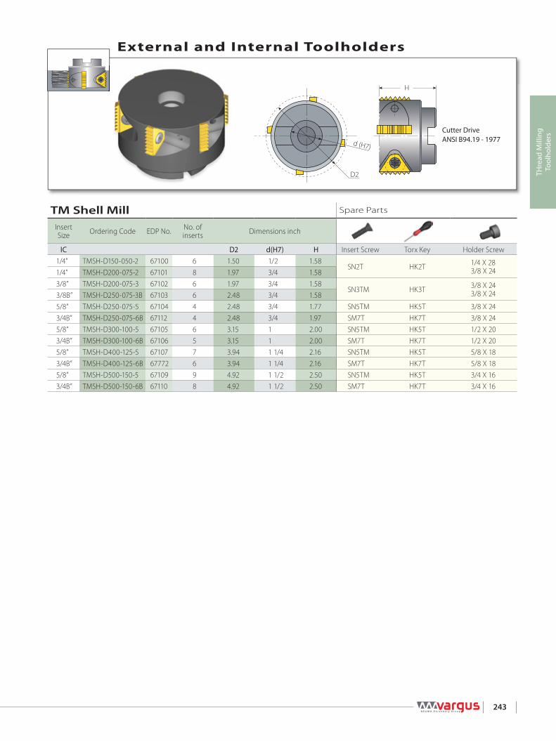
H
D2
d (H7)
TM Shell Mill Spare Parts
Insert Size Ordering Code EDP No. No. of
inserts Dimensions inch
IC D2 d(H7) H Insert Screw Torx Key Holder Screw1/4” TMSH-D150-050-2 67100 6 1.50 1/2 1.58
SN2T HK2T 1/4 X 283/8 X 241/4” TMSH-D200-075-2 67101 8 1.97 3/4 1.58
3/8” TMSH-D200-075-3 67102 6 1.97 3/4 1.58SN3TM HK3T 3/8 X 24
3/8 X 243/8B” TMSH-D250-075-3B 67103 6 2.48 3/4 1.585/8” TMSH-D250-075-5 67104 4 2.48 3/4 1.77 SN5TM HK5T 3/8 X 243/4B” TMSH-D250-075-6B 67112 4 2.48 3/4 1.97 SM7T HK7T 3/8 X 245/8” TMSH-D300-100-5 67105 6 3.15 1 2.00 SN5TM HK5T 1/2 X 203/4B” TMSH-D300-100-6B 67106 5 3.15 1 2.00 SM7T HK7T 1/2 X 205/8” TMSH-D400-125-5 67107 7 3.94 1 1/4 2.16 SN5TM HK5T 5/8 X 183/4B” TMSH-D400-125-6B 67772 6 3.94 1 1/4 2.16 SM7T HK7T 5/8 X 185/8” TMSH-D500-150-5 67109 9 4.92 1 1/2 2.50 SN5TM HK5T 3/4 X 163/4B” TMSH-D500-150-6B 67110 8 4.92 1 1/2 2.50 SM7T HK7T 3/4 X 16
243
THre
ad M
illin
gTo
olho
lder
s
External and Internal Toolholders
Cutter DriveANSI B94.19 - 1977

244
THre
ad M
illin
gTo
olho
lder
s
Spare Parts For VARDEX TM and TMSH Toolholders
Insert IC Holder Holder Screw Insert Screw Torx Key
Designation Thread6.0mm TMMC..-6.0 SN7T M2.2x0.45x5.0 K7T1/4” TM.C..-2 SN2TM M2.6x0.45x5.9 K2T3/8” TM.C..-3, TMC..-3 124/... SN3T, SN3TM UNC5x9.5, 8.0 K3T3/8”B BTM.C..-3B SN3T UNC5x.9.5 K3T1/2” TMC..-4 124/... SN4TM, SA4TM UNC8x10.7, 11.6 K4T5/8” TM.C..-5, TMC..-5 124/... SN5TM, SA5TM M5x0.8x15.0 K5T3/4”B TM.C..-6B SM7T M7x1.0x15.0 K30T1/4” TMSH-D150-050-2 1/4 - 28 X 1.25, 3/8 X 24 SN2T M2.6x0.45x6.5 HK2T1/4” TMSH-D200-075-2 3/8 - 24 X 1.25 SN2T M2.6x0.45x6.5 HK2T3/8” TMSH-D200-075-3 3/8 - 24 X 1.25, 3/8 X 24 SN3TM UNC5x8.0 HK3T3/8”B TMSH-D250-075-3B 3/8 - 24 X 1.25 SN3TM UNC5x8.0 HK3T5/8” TMSH-D250-075-5 3/8 - 24 X 1.25 SN5TM M5x0.8x15.0 HK5T3/4”B TMSH-D250-075-6B 3/8 - 24 X 1.25 SM7T M7x1.0x15.0 HK7T5/8” TMSH-D300-100-5 1/2 - 20 X 1.5 SN5TM M5x0.8x15.0 HK5T3/4”B TMSH-D300-100-6B 1/2 - 20 X 1.5 SM7T M7x1.0x15.0 HK7T5/8” TMSH-D400-125-5 5/8 - 18 X 1.5 SN5TM M5x0.8x15.0 HK5T3/4”B TMSH-D400-125-6B 5/8 - 18 X 1.5 SM7T M7x1.0x15.0 HK7T5/8” TMSH-D500-150-5 3/4 - 16 X 1.75 SN5TM M5x0.8x15.0 HK5T3/4”B TMSH-D500-150-6B 3/4 - 16 X 1.75 SM7T M7x1.0x15.0 HK7T

Thread Milling> Technical Data

246
THre
ad M
illin
gTe
chni
cal D
ata For more Technical Data
see our TM Handbook
About Thread Milling ......................................................................................................................................................................Page 247
Tangential Arc Approach & Radial Approach ..................................................................................................................Page 248
Preparing for the Thread Milling Operation .....................................................................................................................Page 249
“G” Codes for CNC Program ........................................................................................................................................................Page 250
Grades and Their Applications ..................................................................................................................................................Page 250
Recommended Cutting Speeds ..............................................................................................................................................Page 251
Minimum Bore Diameters for Thread Milling ..................................................................................................................Page 252
Troubleshooting ................................................................................................................................................................................Page 254
THREAD MILLING TECHNICAL DATA

AO
B
Z
X
Yα
p
D
Fig. A Fig. B
α: helix angleD: external diameterp: pitch
247
THre
ad M
illin
gTe
chni
cal D
ata
u Tangential Arc Approach
v Radial Approach
w Tangential Line Approach
The thread milling operation (Fig. B) consists of circular rotation of the tool around its own axis together with an orbiting motion along the bore or workpiece circumference.During one such orbit, the tool will shift vertically one pitch length. These movements combined with the insert geometry create the required thread form.There are three acceptable ways of approaching the workpiece with the tool to initiate production of the thread:
About Thread MillingIn order to perform a thread milling operation, a milling machine with three-axis control capable of helical interpolation is required. Helical interpolation is a CNC function producing tool movement along a helical path. This helical motion combines circular movement in one plane with a simultaneous linear motion in a plane perpendicular to the first. For example, the path from point A to point B (Fig. A) on the envelope of the cylinder combines a circular movement in the xy plane with a linear displacement in the z direction.On most CNC systems this function can be executed in two different ways:
GO2: Helical interpolation in a clockwise directionGO3: Helical interpolation in a counter-clockwise direction
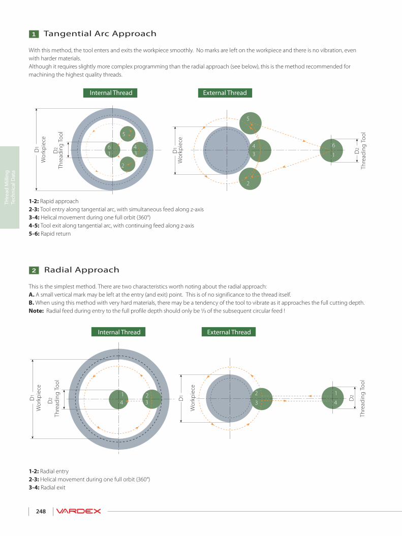
D2
2
5
34
1
6
2
1 36 4
5
D1D1
D2
1 24 3
2 1
3 4 D2
D1D1
D2
248
THre
ad M
illin
gTe
chni
cal D
ata
1-2: Radial entry2-3: Helical movement during one full orbit (360°)3-4: Radial exit
v Radial Approach
This is the simplest method. There are two characteristics worth noting about the radial approach:A. A small vertical mark may be left at the entry (and exit) point. This is of no significance to the thread itself.B. When using this method with very hard materials, there may be a tendency of the tool to vibrate as it approaches the full cutting depth.Note: Radial feed during entry to the full profile depth should only be 1/3 of the subsequent circular feed !
1-2: Rapid approach2-3: Tool entry along tangential arc, with simultaneous feed along z-axis3-4: Helical movement during one full orbit (360°)4-5: Tool exit along tangential arc, with continuing feed along z-axis5-6: Rapid return
u Tangential Arc Approach
With this method, the tool enters and exits the workpiece smoothly. No marks are left on the workpiece and there is no vibration, even with harder materials.Although it requires slightly more complex programming than the radial approach (see below), this is the method recommended for machining the highest quality threads.
Thre
adin
g To
ol
Thre
adin
g To
ol
Wor
kpie
ce
Wor
kpie
ce
External ThreadInternal Thread
Thre
adin
g To
ol
Thre
adin
g To
ol
Wor
kpie
ce
Wor
kpie
ce
External ThreadInternal Thread

D22
3
1
4
D1
D 2
N
Vc
ØD2
F2
F1 ØDi
F2=F1 X (Di + D2)
Di
F1= F2 X DiDi + D2
ØDo
ØD2
F2F1
F2= F1 X (Do - D2)Do
F1= F2 X DoDo - D2
249
THre
ad M
illin
gTe
chni
cal D
ata
On most CNC machines, the feed rate required for programming is that of the center-line of the tool. When dealing with linear tool movement, the feed rate at the cutting edge and the center line are identical, but with circular tool movement, such is not the case.The equations define the relationship between feed rates at the cutting edge and at the tool center line.
v Calculation of Feed Rates at the Tool Center Line
12V = N x π x D2
π x D2N = 12 x V
F1 = N x z x f
N - Rotational Velocity [R.P.M.]
V - Cutting Speed [ft/min]
D2 - Toolholder Cutting Dia. [inch]
F1 - Tool Feed Rate at the Cutting Edge [inch/min]
z - No. of Cutting Edges
f - Feed per Tooth per Rotation [inch/rev]
Preparing for the Thread Milling Operation
u Calculation of Rotational Velocity and Feed at the Cutting Edge
1-2: Radial entry with simultaneous feed along z axis2-3: Helical movement during one full orbit (360°)3-4: Radial exit
w Tangential Line Approach
This method is very simple, and has all of the advantages of the tangential arc method. However, it is applicable only with external threads.
Thread
External Thread
ThreadingTool
ThreadingTool
Thread
Internal Thread
Thre
adin
g To
ol
Wor
kpie
ceExternal Thread

250
THre
ad M
illin
gTe
chni
cal D
ata
List of “G” Codes (ISO) for CNC Program
Code Description Code Description
% Recognition code (ISO or EIA), +End of tape H Tool length compensation numberG00 Fast feed linear positioning D Tool radius compensation numberG01 Linear interpolation X X coordinateG02 Circular/Helical interpolation CW Y Y coordinateG03 Circular/Helical interpolation CCW Z Z coordinateG40 Cutter radius compensation cancel R Radius of travelG41 Cutter radius compensation left I X coordinate to center of starting arc travelG42 Cutter radius compensation right J Y coordinate to center of starting arc travelG43 Tool length compensation + M3 Spindle forward rotationG49 Tool length compensation cancel M5 Spindle stopG57 Work coordinate system selection M30 Program end & rewindG90 Absolute command relative to work coordinate origin O Program numberG91 Incremental command relative to tool position N Block number (can be avoided)F Feed mm/min ( Start of commentS Spindle speed RPM ) End of comment
Grades and Their Applications
Grade Application Sample
VBXFirst choice for steel and cast iron A tough sub-micron substrate with TiCN coating Provides good fracture toughness and excellent wear resistance
VTXFirst choice for stainless steel A tough sub-micron substrate with TiAlN coating Provides good fracture toughness and excellent wear resistance
VK2 Uncoated grade for machining cast iron & nonferrous metals

2
1 36 4
5
251
THre
ad M
illin
gTe
chni
cal D
ata
Tool entry along tangential arcRecommendation: At tool entry, set the Feed f [inch/tooth] to 70% lower than the threading Feed.
Example:Threading Feed: 0.01[inch/tooth]Tool entry Feed: 0.003[inc/tooth]
Recommended Grades, Cutting Speeds Vc [ft/min] and Feed f [inch/tooth]
Material Group
Vard
ex N
o.Material Hardness
Brinell HB
Vc [ft/min] Feedf[inch/tooth]Coated Uncoated
VBX VTX VK2 Indexable Inserts
PSteel
1Unalloyed steel
Low carbon (C=0.1-0.25%) 125 328 - 688 295 - 590 0.002 - 0.0122 Medium carbon (C=0.25-0.55%) 150 328 - 590 295 - 557 0.002 - 0.0103 High Carbon (C=0.55-0.85%) 170 328 - 557 295 - 524 0.002 - 0.0084
Low alloy steel(alloying elements≤5%)
Non hardened 180 295 - 524 295 - 508 0.002 - 0.0105 Hardened 275 262 - 590 262 - 524 0.002 - 0.0086 Hardened 350 229 - 459 229 - 492 0.002 - 0.0067 High alloy steel
(alloying elements>5%) Annealed 200 197 - 426 229 - 377 0.002 - 0.008
8 Hardened 325 229 - 361 197 - 328 0.002 - 0.0049
Cast steel Low alloy (alloying elements <5%) 200 328 - 557 328 - 557 328 - 492 0.002 - 0.006
10 High alloy (alloying elements >5%) 225 229 - 393 229 - 426 197 - 426 0.002 - 0.004
MStainless
Steel
11 Stainless steel Feritic
Non hardened 200 328 - 557 393 - 590 0.002 - 0.00612 Hardened 330 328 - 557 393 - 590 0.002 - 0.00413 Stainless steel
Austenitic Austenitic 180 229 - 459 328 - 459 0.002 - 0.006
14 Super Austenitic 200 229 - 459 328 - 459 0.002 - 0.00415 Stainless steel
Cast Feritic Non hardened 200 229 - 459 328 - 459 0.002 - 0.006
16 Hardened 330 229 - 459 328 - 459 0.002 - 0.00417 Stainless steel
Cast austenitic Austenitic 200 229 - 393 328 - 393 0.002 - 0.006
18 Hardened 330 229 - 393 328 - 393 0.002 - 0.004
KCast Iron
28 Malleable Cast iron
Ferritic (short chips) 130 197 - 426 328 - 393 0.001 - 0.03129 Pearlitic (long chips) 230 197 - 393 262 - 328 0.001 - 0.00230
Grey cast iron Low tensile strength 180 197 - 426 262 - 328 0.002 - 0.006
31 High tensile strength 260 197 - 328 262 - 328 0.002 - 0.00432
Nodular SG iron Feritic 160 197 - 410 262 - 328 0.002 - 0.006
33 Pearlitic 260 164 - 295 197 - 295 0.002 - 0.004
N(K)Non-Ferrous
Metals
34 Aluminium alloys Wrought
Non aging 60 328 - 820 656 - 983 0.004 - 0.01635 Aged 100 328 - 590 197 - 361 0.004 - 0.01236
Aluminium alloys Cast 75 492 - 1,311 197 - 393 0.004 - 0.012
37 Cast & aged 90 492 - 918 197 - 328 0.002 - 0.01038 Aluminium alloys Cast Si 13-22% 130 262 - 492 66 - 164 0.004 - 0.01239 Copper and
copper alloys Brass 90 393 - 688 328 - 656 164 - 229 0.004 - 0.012
40 Bronze and non leaded copper 100 393 - 688 328 - 656 164 - 229 0.002 - 0.010
S(M)Heat
ResistantMaterial
19
High temperaturealloys
Annealed (Iron based ) 200 66 - 148 66 - 131 66 - 98 0.002 - 0.00420 Aged (Iron based) 280 66 - 98 66 - 98 49 - 82 0.001 - 0.00221 Annealed (Nickel or Cobalt based) 250 66 - 164 49 - 66 49 - 66 0.001 - 0.00222 Aged (Nickel or Cobalt based) 350 33 - 49 33 - 49 33 - 49 0.001 - 0.00223
Titanium alloys Pure 99.5 Ti 400Rm 229 - 459 229 - 393 131 - 197 0.001 - 0.002
24 α+β alloys 1050Rm 66 - 164 66 - 164 66 - 131 0.001 - 0.002
H(K)Hardned Material
25
Extra hard steel Hardened & tempered
45-50HRc 66 - 148 66 - 148 0.001
26 51-55HRc 66 - 148 66 - 148 0.001
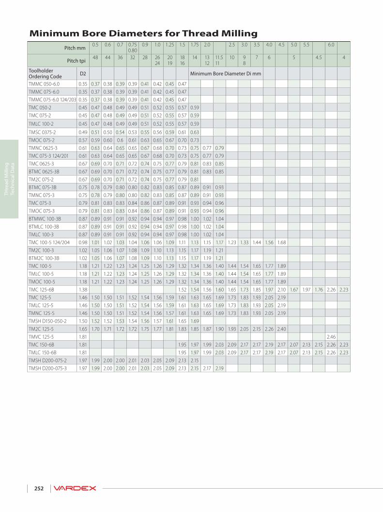
252
THre
ad M
illin
gTe
chni
cal D
ata
Minimum Bore Diameters for Thread MillingPitch mm
0.5 0.6 0.7 0.75 0.80
0.9 1.0 1.25 1.5 1.75 2.0 2.5 3.0 3.5 4.0 4.5 5.0 5.5 6.0
Pitch tpi48 44 36 32 28 26
2420 19
18 16
14 13 12
11.5 11
10 9 8
7 6 5 4.5 4
ToolholderOrdering Code D2 Minimum Bore Diameter Di mm
TMMC 050-6.0 0.35 0.37 0.38 0.39 0.39 0.41 0.42 0.45 0.47TMMC 075-6.0 0.35 0.37 0.38 0.39 0.39 0.41 0.42 0.45 0.47TMMC 075-6.0 124/203 0.35 0.37 0.38 0.39 0.39 0.41 0.42 0.45 0.47TMC 050-2 0.45 0.47 0.48 0.49 0.49 0.51 0.52 0.55 0.57 0.59TMC 075-2 0.45 0.47 0.48 0.49 0.49 0.51 0.52 0.55 0.57 0.59
TMLC 100-2 0.45 0.47 0.48 0.49 0.49 0.51 0.52 0.55 0.57 0.59
TMSC 0375-2 0.49 0.51 0.50 0.54 0.53 0.55 0.56 0.59 0.61 0.63TMOC 075-2 0.57 0.59 0.60 0.6 0.61 0.63 0.65 0.67 0.70 0.73TMNC 0625-3 0.61 0.63 0.64 0.65 0.65 0.67 0.68 0.70 0.73 0.75 0.77 0.79TMC 075-3 124/201 0.61 0.63 0.64 0.65 0.65 0.67 0.68 0.70 0.73 0.75 0.77 0.79TMC 0625-3 0.67 0.69 0.70 0.71 0.72 0.74 0.75 0.77 0.79 0.81 0.83 0.85BTMC 0625-3B 0.67 0.69 0.70 0.71 0.72 0.74 0.75 0.77 0.79 0.81 0.83 0.85TM2C 075-2 0.67 0.69 0.70 0.71 0.72 0.74 0.75 0.77 0.79 0.81BTMC 075-3B 0.75 0.78 0.79 0.80 0.80 0.82 0.83 0.85 0.87 0.89 0.91 0.93TMNC 075-3 0.75 0.78 0.79 0.80 0.80 0.82 0.83 0.85 0.87 0.89 0.91 0.93TMC 075-3 0.79 0.81 0.83 0.83 0.84 0.86 0.87 0.89 0.91 0.93 0.94 0.96TMOC 075-3 0.79 0.81 0.83 0.83 0.84 0.86 0.87 0.89 0.91 0.93 0.94 0.96BTMWC 100-3B 0.87 0.89 0.91 0.91 0.92 0.94 0.94 0.97 0.98 1.00 1.02 1.04BTMLC 100-3B 0.87 0.89 0.91 0.91 0.92 0.94 0.94 0.97 0.98 1.00 1.02 1.04TMLC 100-3 0.87 0.89 0.91 0.91 0.92 0.94 0.94 0.97 0.98 1.00 1.02 1.04TMC 100-5 124/204 0.98 1.01 1.02 1.03 1.04 1.06 1.06 1.09 1.11 1.13 1.15 1.17 1.23 1.33 1.44 1.56 1.68TM2C 100-3 1.02 1.05 1.06 1.07 1.08 1.09 1.10 1.13 1.15 1.17 1.19 1.21BTM2C 100-3B 1.02 1.05 1.06 1.07 1.08 1.09 1.10 1.13 1.15 1.17 1.19 1.21TMC 100-5 1.18 1.21 1.22 1.23 1.24 1.25 1.26 1.29 1.32 1.34 1.36 1.40 1.44 1.54 1.65 1.77 1.89TMLC 100-5 1.18 1.21 1.22 1.23 1.24 1.25 1.26 1.29 1.32 1.34 1.36 1.40 1.44 1.54 1.65 1.77 1.89TMOC 100-5 1.18 1.21 1.22 1.23 1.24 1.25 1.26 1.29 1.32 1.34 1.36 1.40 1.44 1.54 1.65 1.77 1.89TMC 125-6B 1.38 1.52 1.54 1.56 1.60 1.65 1.73 1.85 1.97 2.10 1.67 1.97 1.76 2.26 2.23TMC 125-5 1.46 1.50 1.50 1.51 1.52 1.54 1.56 1.59 1.61 1.63 1.65 1.69 1.73 1.83 1.93 2.05 2.19TMLC 125-5 1.46 1.50 1.50 1.51 1.52 1.54 1.56 1.59 1.61 1.63 1.65 1.69 1.73 1.83 1.93 2.05 2.19TMNC 125-5 1.46 1.50 1.50 1.51 1.52 1.54 1.56 1.57 1.61 1.63 1.65 1.69 1.73 1.83 1.93 2.05 2.19TMSH D150-050-2 1.50 1.52 1.52 1.53 1.54 1.56 1.57 1.61 1.65 1.69TM2C 125-5 1.65 1.70 1.71 1.72 1.72 1.75 1.77 1.81 1.83 1.85 1.87 1.90 1.93 2.05 2.15 2.26 2.40TMVC 125-5 1.81 2.46TMC 150-6B 1.81 1.95 1.97 1.99 2.03 2.09 2.17 2.17 2.19 2.17 2.07 2.13 2.15 2.26 2.23TMLC 150-6B 1.81 1.95 1.97 1.99 2.03 2.09 2.17 2.17 2.19 2.17 2.07 2.13 2.15 2.26 2.23TMSH D200-075-2 1.97 1.99 2.00 2.00 2.01 2.03 2.05 2.09 2.13 2.15TMSH D200-075-3 1.97 1.99 2.00 2.00 2.01 2.03 2.05 2.09 2.13 2.15 2.17 2.19

253
THre
ad M
illin
gTe
chni
cal D
ata
Minimum Bore Diameters for Thread Milling (con't)
Pitch mm0.5 0.6 0.7 0.75
0.800.9 1.0 1.25 1.5 1.75 2.0 2.5 3.0 3.5 4.0 4.5 5.0 5.5 6.0
Pitch tpi48 44 36 32 28 26
2420 19
18 16
14 13 12
11.5 11
10 9 8
7 6 5 4.5 4
ToolholderOrdering Code D2 Minimum Bore Diameter Di mm
TM2C 150-6B 2.05 2.20 2.21 2.22 2.24 2.32 2.42 2.48 2.52 2.60 2.64 2.66 2.72 2.76TMSH D250-075-3B 2.48 2.5 2.51 2.52 2.52 2.54 2.56 2.6 2.64 2.66 2.68 2.72TMSH D250-075-5 2.48 2.5 2.51 2.52 2.52 2.54 2.56 2.6 2.64 2.66 2.68 2.72 2.76 2.83 2.87 2.91 2.95TMSH D250-075-6B 2.48 2.64 2.66 2.68 2.72 2.76 2.83 2.87 2.91 2.95 3.03 3.07 3.09 3.15 3.19TMSH D300-100-5 3.15 3.17 3.18 3.19 3.19 3.21 3.23 3.27 3.31 3.33 3.35 3.39 3.43 3.50 3.54 3.58 3.62
TMSH D300-100-6B 3.15 3.31 3.33 3.35 3.39 3.43 3.50 3.54 3.58 3.62 3.70 3.74 3.76 3.82 3.86
TMSH D400-125-5 3.94 3.96 3.96 3.97 3.98 4.00 4.02 4.06 4.09 4.11 4.13 4.17 4.21 4.29 4.33 4.37 4.41TMSH D400-125-6B 3.94 4.09 4.11 4.13 4.17 4.21 4.29 4.33 4.37 4.41 4.49 4.53 4.55 4.61 4.65TMSH D500-150-5 4.92 4.94 4.95 4.96 4.96 4.98 5.00 5.04 5.08 5.10 5.12 5.16 5.20 5.28 5.31 5.35 5.39TMSH D500-50-6B 4.92 5.08 5.10 5.12 5.16 5.20 5.28 5.31 5.35 5.39 5.47 5.51 5.54 5.59 5.63
Coarse Pitch Tooling:This table is not applicable to the Coarse Pitch system, which can thread mill bores smaller than those listed above. See the Coarse Pitch section of the various thread standards.

254
THre
ad M
illin
gTe
chni
cal D
ata
Problem Possible Cause Solution
Increasedinsert flank wear
Cutting speed too high --------------➤Chip is too thin -------------------------➤Insufficient coolant --------------------➤
Reduce cutting speed/use coated insertIncrease feed rateIncrease coolant flow rate
Chipping of cutting edge
Chip is too thick ----------------------➤
Vibration --------------------------------➤
Reduce feed rateUse the tangential arc methodIncrease RPMCheck stability
Materialbuild upon the cutting edge
Incorrect cutting speed --------------➤Unsuitable carbide grade ------------➤
Change cutting speedUse a coated carbide grade
Chatter /Vibration
Feed rate is too high ------------------➤Profile is too deep ---------------------➤
Thread length is too long ------------➤
Reduce the feedExecute two passes, each with increased cutting depthExecute two passes, each cutting only half the thread lengthExecute two passes, each cutting only half the thread length
GO NOGO
Insufficientthreadaccuracy
Tool deflection ------------------------➤ Reduce feed rateExecute a “zero” cut
Troubleshooting

> Inserts> Toolholders> Technical Data
Super Fast Thread Milling System

256
MIT
M
VARDEX Ordering Code System ..............................................................................................................................................Page 258
Inserts American UN .......................................................................................................................................................................................Page 259
ISO Metric ..............................................................................................................................................................................................Page 260
NPT ............................................................................................................................................................................................................Page 261
NPTF .........................................................................................................................................................................................................Page 261
Whitworth for BSF, BSP .................................................................................................................................................................Page 262
BSPT ..........................................................................................................................................................................................................Page 263
Toolholders Standard Toolholders (MiTM 24) .............................................................................................................................................Page 264
Conical Toolholders (MiTM 24) ................................................................................................................................................Page 265
Standard Toolholders (MiTM 25) .............................................................................................................................................Page 266
Conical Toolholders (MiTM 25) ................................................................................................................................................Page 267
Shell Mill (MiTM 25) .........................................................................................................................................................................Page 268
Standard Toolholders (MiTM 40) .............................................................................................................................................Page 269
Shell Mill (MiTM 40) .........................................................................................................................................................................Page 270
Standard Toolholders (MiTM 41) .............................................................................................................................................Page 271
Shell Mill (MiTM 41) .........................................................................................................................................................................Page 272
Technical Data Recommended Cutting Speeds and Feed .......................................................................................................................Page 273
TM Gen Software and updated versions can be downloaded from www.vargususa.com
MiTM - MULTI-FLUTE INDEXABLE THREAD MILLING
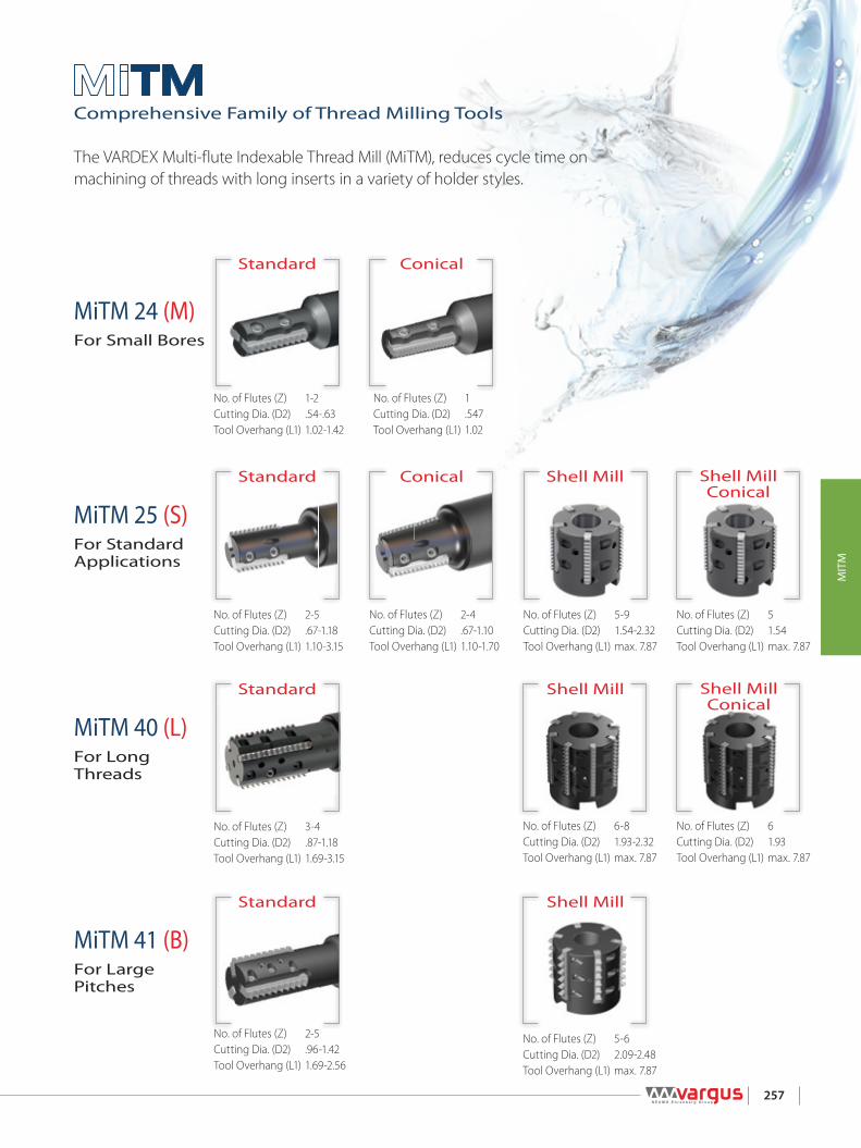
257
MIT
M
MiTM 41 (B)For Large Pitches
MiTM 40 (L)For Long Threads
MiTM 25 (S)For Standard Applications
MiTM 24 (M)For Small Bores
Shell MillConical
Shell MillConical
Shell Mill
Shell Mill
Shell MillConical
Conical
Standard
Standard
Standard
Standard
Comprehensive Family of Thread Milling Tools
The VARDEX Multi-flute Indexable Thread Mill (MiTM), reduces cycle time on machining of threads with long inserts in a variety of holder styles.
No. of Flutes (Z) 1-2Cutting Dia. (D2) .54-.63Tool Overhang (L1) 1.02-1.42
No. of Flutes (Z) 3-4Cutting Dia. (D2) .87-1.18Tool Overhang (L1) 1.69-3.15
No. of Flutes (Z) 2-5Cutting Dia. (D2) .67-1.18Tool Overhang (L1) 1.10-3.15
No. of Flutes (Z) 2-5Cutting Dia. (D2) .96-1.42Tool Overhang (L1) 1.69-2.56
No. of Flutes (Z) 1Cutting Dia. (D2) .547Tool Overhang (L1) 1.02
No. of Flutes (Z) 6-8Cutting Dia. (D2) 1.93-2.32Tool Overhang (L1) max. 7.87
No. of Flutes (Z) 2-4Cutting Dia. (D2) .67-1.10Tool Overhang (L1) 1.10-1.70
No. of Flutes (Z) 5-6Cutting Dia. (D2) 2.09-2.48Tool Overhang (L1) max. 7.87
No. of Flutes (Z) 5-9Cutting Dia. (D2) 1.54-2.32Tool Overhang (L1) max. 7.87
No. of Flutes (Z) 5Cutting Dia. (D2) 1.54Tool Overhang (L1) max. 7.87
No. of Flutes (Z) 6Cutting Dia. (D2) 1.93Tool Overhang (L1) max. 7.87

258
MIT
M
Ordering Code System
R1
252
I3
1.004
ISO5
TM6
VBX7
1- Product Line
R- MiTM line
2 - Insert Style
24, 25, 40, 41
4 - Pitch
0.5-6.0 mm32-4 tpi
6 - System
TM
5 - Standard
ISO- ISO MetricUN-American UNW- BSW, BSPNPT-NPTNPTF-NPTFBSPT-BSPT
7 - Carbide GradeVBXVTX
3 - Type of Insert
I - InternalE - ExternalEI-External+InternalNC- Plug
R1
R1
TM2
TM2
C3
C3
1004
D1504
0675
0505
-
-
1106
25S6
S7
57
28
1- Product Line
R - MiTM lineBR - MiTM with anti vibration system
1- Product Line
R - MiTM line
6 - Insert Style
25S 40L 41B
2 - Holder Type
TM - Standard holderTMN - Conical holder
2 - Holder Type
TM - Standard holderTMN - Conical holder
7 - No. of Flutes
5 - 9
4 - Shank Dia. [inch]
1, 1.25
4 - Cutting Dia. [inch]
1.54-2.48
7 - Insert Style
M - 24S - 25L - 40B - 41
5 - Cutting Dia. [inch]
.54-1.42
5 - Drive Hole Dia. [inch]
.5, .75, 1
8 - No. of Flutes
1 - 5
3 - Cooling
C- Coolant Channel
3 - Cooling
C- Coolant Channel
6 - Tool Overhang [inch]
1.02-3.15
MiTM Holders (Standard and Conical)
MiTM Shell Mill
MiTM Inserts

259
MIT
M
1/4P
1/8P
60°
Defined by: ANSI B1.1:74Tolerance class: 2A/2B
L
L
Le
Le
MiTM 24
MiTM 25L
L
Le
Le
MiTM 41
MiTM 40
External
Internal
Standard MiTML Pitch Ordering Code EDP NO. Ordering Code EDP NO. Cutting
Edge Teeth Toolholder
inch tpi External VTX VBX Internal VTX VBX Le Zt
.945"(24 mm)
32 R24I32UNTM... 80796 80797 1 0.97 31
RTMC....M
28 R24I28UNTM... 80798 80799 1 0.96 2724 R24I24UNTM... 80802 80803 1 0.96 2320 R24I20UNTM... 80804 80805 1 0.95 1918 R24I18UNTM... 80806 80807 1 0.94 1716 R24I16UNTM... 80808 80809 1 0.94 1514 R24I14UNTM... 80810 80811 1 0.93 1312 R24I12UNTM... 80812 80813 1 0.92 1110 R24I10UNTM... 80814 80815 1 0.90 9
988”(25 mm)
20 R25E20UNTM... 80594 80595 R25I20UNTM... 80492 80493 2 0.95 19
(B)RTMC....S
18 R25E18UNTM... 80596 80597 R25I18UNTM... 80494 80495 2 0.94 1716 R25E16UNTM... 80598 80599 R25I16UNTM... 80496 80497 2 0.94 1514 R25E14UNTM... 80600 80601 R25I14UNTM... 80498 80499 2 0.93 1312 R25E12UNTM... 80602 80603 R25I12UNTM... 80500 80501 2 0.92 1110 R25E10UNTM... 80604 80605 R25I10UNTM... 80502 80503 2 0.90 99 *R25E9UNTM... 80606 80607 *R25I9UNTM... 80504 80505 2 0.89 8
* See note below8 *R25E8UNTM... 80608 80609 *R25I8UNTM... 80506 80507 2 0.87 7
1.575" (40 mm)
20 R40I20UNTM... 80712 80713 2 1.55 31
(B)RTMC....L
18 R40I18UNTM... 80714 80715 2 1.56 2816 R40I16UNTM... 80716 80717 2 1.56 2514 R40I14UNTM... 80718 80719 2 1.57 2212 R40I12UNTM... 80720 80721 2 1.50 1810 R40I10UNTM... 80722 80723 2 1.50 159 R40I9UNTM... 80724 80725 2 1.56 148 R40I8UNTM... 80726 80727 2 1.50 12
1.614"(41 mm)
8 R41E8UNTM... 80816 80817 R41I8UNTM... 80828 80829 2 1.50 12
RTMC....B
7 R41E7UNTM... 80818 80819 R41I7UNTM... 80830 80831 2 1.57 116 R41E6UNTM... 80820 80821 R41I6UNTM... 80832 80833 2 1.50 95 R41E5UNTM... 80822 80823 R41I5UNTM... 80834 80835 2 1.40 7
4.5 R41E4.5UNTM... 80824 80825 R41I4.5UNTM... 80836 80837 2 1.56 74 R41E4UNTM... 80826 80827 R41I4UNTM... 80838 80839 2 1.50 6
* Note: 8 UN & 9 UN inserts do not fit into toolholder RTMC100067....For external insert 8 UN use for CNC program (D2 + 0.02")
MiTM inserts 25, 40 and 41 are offered with 2 cutting edges. In case of chip flow difficulty, inserts with a single cutting edge can be ordered by request. Example: R25I20UNTM(S)...
Defined by: ANSI B1.1:74Tolerance class: 2A/2B
External / Internal
American UN

260
MIT
M
1/4P
1/8P
60°
Defined by: R262 (DIN 13)Tolerance class: 6g/6H External
Internal
Standard MiTML Pitch Ordering Code EDP No. Ordering Code EDP No. Cutting
Edge Teeth Toolholder
inch tpi External VTX VBX Internal VTX VBX Le Zt
.945"(24 mm)
0.50 R24I0.50ISOTM... 80753 80754 1 0.96 49
RTMC....M
0.75 R24I0.75ISOTM... 80755 80751 1 0.97 331.00 R24I1.00ISOTM... 80756 80757 1 0.94 241.25 R24I1.25ISOTM... 80758 80759 1 0.98 201.50 R24I1.50ISOTM... 80760 80761 1 0.94 161.75 R24I1.75ISOTM... 80762 80763 1 0.96 142.00 R24I2.00ISOTM... 80764 80765 1 0.94 122.50 R24I2.50ISOTM... 80766 80767 1 0.98 10
.988”(25 mm)
1.00 R25E1.00ISOTM... 80584 80585 R25I1.00ISOTM... 80482 80483 2 0.94 24
(B)RTMC....S1.50 R25E1.50ISOTM... 80587 80586 R25I1.50ISOTM... 80484 80485 2 0.94 162.00 R25E2.00ISOTM... 80588 80589 R25I2.00ISOTM... 80486 80487 2 0.94 122.50 R25E2.50ISOTM... 80590 80591 R25I2.50ISOTM... 80488 80489 2 0.98 103.00 *R25E3.00ISOTM... 80592 80593 *R25I3.00ISOTM... 80490 80491 2 0.94 8 * See note below
1.575" (40 mm)
1.00 R40I1.00ISOTM... 80702 80703 2 1.54 39
(B)RTMC....L1.50 R40I1.50ISOTM... 80704 80705 2 1.54 262.00 R40I2.00ISOTM... 80706 80707 2 1.50 192.50 R40I2.50ISOTM... 80708 80709 2 1.48 153.00 R40I3.00ISOTM... 80710 80711 2 1.54 13
1.614"(41 mm)
3.00 R41E3.00ISOTM... 80768 80769 R41I3.00ISOTM... 80782 80783 2 1.54 13
RTMC....B
3.50 R41E3.50ISOTM... 80770 80771 R41I3.50ISOTM... 80784 80785 2 1.52 114.00 R41E4.00ISOTM... 80772 80773 R41I4.00ISOTM... 80786 80787 2 1.57 104.50 R41E4.50ISOTM... 80774 80775 R41I4.50ISOTM... 80788 80789 2 1.59 95.00 R41E5.00ISOTM... 80776 80777 R41I5.00ISOTM... 80790 80791 2 1.57 85.50 R41E5.50ISOTM... 80778 80779 R41I5.50ISOTM... 80792 80793 2 1.52 76.00 R41E6.00ISOTM... 80780 80781 R41I6.00ISOTM... 80794 80795 2 1.42 6
L
L
Le
Le
MiTM 24
MiTM 25L
L
Le
Le
MiTM 41
MiTM 40
* Note: 3.00 ISO inserts do not fit into toolholder RTMC100067....For external insert 3.0 ISO use for CNC program (D2 + 0.02")
MiTM inserts 25, 40 and 41 are offered with 2 cutting edges. In case of chip flow difficulty, inserts with a single cutting edge can be ordered by request. Example: R25I2.00ISOTM(S)...
Defined by: R262 (DIN 13)Tolerance class: 6g/6H
External / Internal
ISO Metric

261
MIT
M
30°30°
90° 1°47’Defined by: ANSI B1.20.3-1976Tolerance class: Standard NPTF
Defined by: USAS B2.1:1968Tolerance class: Standard NPT Extern
Intern30°30°
90° 1°47’
MiTM Inserts - 25mm
R25NC Plug Insert
External** / Internal
MiTM Inserts - 25mm
R25NC Plug Insert
External** / Internal
1 4̊7'
MiTM Inserts - 25mm
R25NC Plug Insert
External** / Internal
MiTM Inserts - 25mm
R25NC Plug Insert
External** / Internal
1 4̊7'
L
Le
L
L
Le
Le
1˚47'
1˚47'
MiTM 25
MiTM 24L
1˚47'
Le
MiTM 41
MiTM 40
L
Le
L
L
Le
Le
1˚47'
1˚47'
MiTM 25
MiTM 24L
1˚47'
Le
MiTM 41
MiTM 40
External
Internal
External
Internal
Standard MiTML Pitch Ordering Code EDP No. Cutting
Edge Teeth Toolholder
inch tpi External + Internal VTX VBX Le Zt
.945"(24 mm) 18 R24EI18NPTFTM... 80875 80876 1 0.94 17 RTMNC....M
.988”(25 mm)
14 R25EI14NPTFTM... 80520 80521 1 0.93 13RTMNC....S
11.5 R25EI11.5NPTFTM... 80522 80523 1 0.96 11
8 R25EI8NPTFTM... 80582 80583 1 0.87 7 RTMNC-D150-050-25S5
1.575" (40 mm)
11.5 R40EI11.5NPTFTM... 80745 80746 1 1.48 17RTMNC-D190-075-40L7
8 R40EI8NPTFTM... 80730 80731 1 1.50 12
1.614"(41 mm) 8 R41EI8NPTFTM... 80842 80843 1 1.50 12 RTMC....B
Standard MiTML Pitch Ordering Code EDP No. Cutting
Edge Teeth Toolholder
inch tpi External + Internal VTX VBX Le Zt
.945"(24 mm) 18 R24EI18NPTTM... 80873 80874 1 0.94 17 RTMNC....M
.988”(25 mm)
14 R25EI14NPTTM... 80516 80517 1 0.93 13RTMNC....S
11.5 R25EI11.5NPTTM... 80518 80519 1 0.96 118 R25EI8NPTTM... 80580 80581 1 0.87 7 RTMNC-D150-050-25S5
1.575" (40 mm)
11.5 R40EI11.5NPTTM... 80743 80744 1 1.48 17RTMNC-D190-075-40L7
8 R40EI8NPTTM... 80728 80729 1 1.50 12
1.614"(41 mm) 8 R41EI8NPTTM... 80840 80841 1 1.50 12 RTMC....B
NPTF
Defined by: USAS B2.1:1968Tolerance class: Standard NPT
External / Internal
Defined by: ANSI B1.20.3-1976Tolerance class: Standard NPTF
External / Internal
NPT

262
MIT
M
R 0.137P
55°R 0.137P
Defined by: B.S.84:1956, DIN 259, ISO228/1:1982Tolerance class: Medium Class A External
Internal
Standard MiTML Pitch Ordering Code EDP NO. Ordering Code EDP NO. Cutting
Edge Teeth Toolholder
inch tpi External + Internal VTX VBX Internal VTX VBX Le Zt
.945"(24 mm)
19 R24EI19WTM... 80844 80845 1 0.95 18RTMC....M14 R24EI14WTM... 80846 80847 1 0.93 13
12 R24EI12WTM... 80848 80849 1 0.92 11
.988”(25 mm)
16 R25EI16WTM... 80508 80509 2 0.94 15
(B)RTMC....S14 R25EI14WTM... 80510 80511 2 0.93 1312 R25EI12WTM... 80512 80513 2 0.92 1111 R25EI11WTM... 80514 80515 2 0.91 10
1.575" (40 mm)
16 R40EI16WTM... 80610 80611 2 1.56 25
(B)RTMC....L14 R40EI14WTM... 80612 80613 2 1.57 2212 R40EI12WTM... 80614 80615 2 1.50 1811 R40EI11WTM... 80616 80617 2 1.55 17
1.614"(41 mm)
8 R41I8WTM... 80850 80851 2 1.50 12RTMC....B7 R41I7WTM... 80852 80853 2 1.57 11
6 R41I6WTM... 80854 80855 2 1.50 9
L
L
Le
Le
MiTM 24
MiTM 25L
L
Le
Le
MiTM 41
MiTM 40
MiTM inserts 25, 40 and 41 are offered with 2 cutting edges. In case of chip flow difficulty, inserts with a single cutting edge can be ordered by request. Example: R25EI16WTM(S)...
Defined by: B.S.84:1956, DIN 259, ISO228/1:1982Tolerance class: Medium Class A
External / Internal
Whitworth for BSF, BSP

263
MIT
M
Defined by: B.S. 21:1985Tolerance class: Standard BSPT
R0.137P27.5° 27.5°
90 ° 1 47'° R0.137P
MiTM Inserts - 25mm
R25NC Plug Insert
External** / Internal
MiTM Inserts - 25mm
R25NC Plug Insert
External** / Internal
* Fill unused toolholder pockets with Plug inserts (R..NC). This assures balance and prevents instability and chips from packing into empty pockets.
External
Internal
Plug Insert*L Ordering Code EDP No. Teeth Toolholder
inch External + Internal Zt
.945" (24 mm) R24NC 80858
No Teeth
RTMC....M
All Types.988” (25 mm) R25NC 80532 (B)RTMC....S
1.575" (40 mm) R40NC 80626 (B)RTMC....L1.614" (41 mm) R41NC 80859 RTMC....B
L
L
Le
Le
1˚47'
1˚47'
MiTM 25
MiTM 24L
1˚47'
Le
MiTM 40
Defined by: B.S. 21:1985Tolerance class: Standard BSPT
External / Internal
BSPT
Standard MiTML Pitch Ordering Code EDP No. Cutting
Edge Teeth Toolholder
inch tpi External + Internal VTX VBX Le Zt
.945"(24 mm) 19 R24EI19BSPTTM... 80871 80872 1 0.95 18 RTMNC 075055-102M1
.988”(25 mm)
14 R25EI14BSPTTM... 80524 80525 1 0.93 13RTMNC....S
11 R25EI11BSPTTM... 80526 80527 1 0.91 10
1.575" (40 mm) 11 R40EI11BSPTTM... 80732 80733 1 1.55 17 RTMNC-D190-075-40L7

264
MIT
M
D1
D2
D
LL1
D1
Side with identification marks Side without identification marksAlways mount all inserts with identification marks face up
To mount insert correctly, push the insert toward the pocket walls.
Coolant-Thru is recommended, especially when D2 > 0.7 x nominal thread diameter
Standard Thread Application by Toolholder
Toolholder Min. Thread Ø
D2(inch)
ISO(coarse)
ISO(fine) UNC UN/UNF/UNEF/UNS BSF BSP(G)
RTMC 075053-102M1 0.53 M16x2 M14.5x0.5; M15X0.75; M15x1; M15x1.25; M16x1.5; M16x1.75 -
11⁄16-12UN; 5⁄8-14UNS; 5⁄8-16UN; 5⁄8-18UNF; 5⁄8-20UN; 5⁄8-24UNEF; 5⁄8-28UN; 5⁄8-32UN
11⁄16-14; 3⁄4-12
3⁄8-19
RTMC 075059-118M1 0.59 M18x2.5M16x0.5; M17X0.75; M17x1; M17x1.25; M17x1.5;M18x1.75; M18x2
3⁄4-103⁄4-12UN; 3⁄4-14UNS; 11⁄16-16UN; 11⁄16-20UN;11⁄16-24UNEF; 11⁄16-28UN; 11⁄16-32UN
3⁄4-12 -
RTMC 075063-110M2 0.63 M20x2.5M17x0.5; M17x0.75; M18x1; M18x1.25; M18x1.5;M18x1.75; M19x2
3⁄4-103⁄4-12UN; 3⁄4-14UNS; 3⁄4-16UN; 3⁄4-18UNS; 3⁄4-20UNEF; 11⁄16-24UNEF; 11⁄16-28UN; 11⁄16-32UN
3⁄4-12 -
RTMC 075063-142M1 0.63 M20x2.5M17x0.5; M17x0.75; M18x1; M18x1.25; M18x1.5;M18x1.75; M19x2
3⁄4-103⁄4-12UN; 3⁄4-14UNS; 3⁄4-16UN; 3⁄4-18UNS; 3⁄4-20UNEF; 11⁄16-24UNEF; 11⁄16-28UN; 11⁄16-32UN
3⁄4-12 -
RTMC - for Standard Threads Spare Parts ( Ordering code & EDP No.)
Insert Style Ordering Code EDP No. Dimensions (inch) No. of Flutes
L L1 D D1 D2 Z Location Screw x2 Torx+ Screwdriver
.945"(24 mm)
RTMC 075053-102M1 80860 3.27 1.02 0.75 0.42 0.53 1SLD4IP8(M4x0.7)(80533)
KIP8• Use the included Vardex Torx+ screwdriver only
• Recommended max. torque 10.6 lbfxin
(70231)
RTMC 075059-118M1 80861 3.39 1.18 0.75 0.47 0.59 1RTMC 075063-110M2 80752 3.31 1.10 0.75 0.49 0.63 2RTMC 075063-142M1 80862 3.62 1.42 0.75 0.49 0.63 1
Standard Toolholders (MiTM 24)

265
MIT
M
D1
D
LL1
1°47'
D2
To mount insert correctly, push the insert toward the pocket wallsSide without identification marks
On Conical inserts, the identification mark must face up
Coolant-Thru is recommended, especially when D2 > 0.7 x nominal thread diameter
Standard Thread Application by Toolholder
Toolholder
D2(inch) NPT NPTF BSPT
RTMNC 075055-102M1 0.55 3⁄8-18 3⁄8-18 3⁄8-19
RTMC - for Standard Threads Spare Parts ( Ordering code & EDP No.)
Insert Style Ordering Code EDP No. Dimensions (inch) No. of Flutes
L L1 D D1 D2 Z Location Screw x2 Torx+ Screwdriver
.945"(24 mm) RTMNC 075055-102M1 80863 3.23 1.02 0.75 0.45 0.55 1
SLD4IP8(M4x0.7)(80533)
KIP8• Use the included Vardex Torx+ screwdriver only
• Recommended max. torque 10.6 lbfxin
(70231)
Conical Toolholders (MiTM 24)
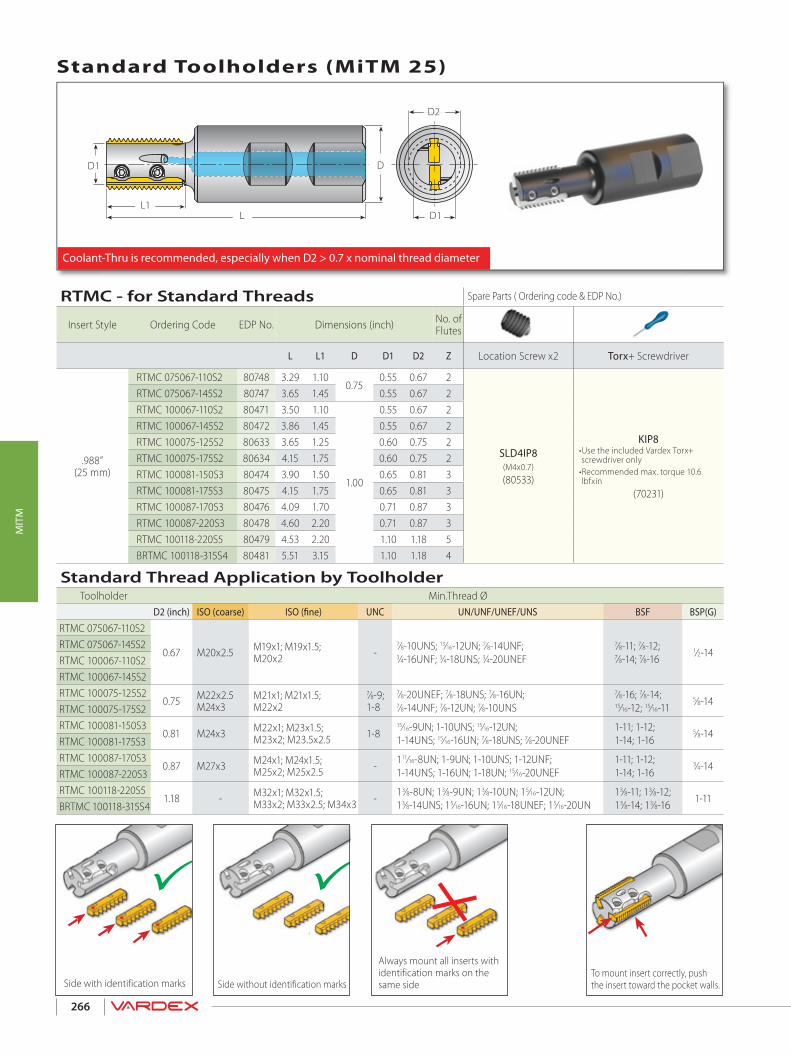
266
MIT
M
RTMC - for Standard Threads Spare Parts ( Ordering code & EDP No.)
Insert Style Ordering Code EDP No. Dimensions (inch) No. of Flutes
L L1 D D1 D2 Z Location Screw x2 Torx+ Screwdriver
.988”(25 mm)
RTMC 075067-110S2 80748 3.29 1.100.75
0.55 0.67 2
SLD4IP8(M4x0.7)(80533)
KIP8• Use the included Vardex Torx+ screwdriver only
• Recommended max. torque 10.6 lbfxin
(70231)
RTMC 075067-145S2 80747 3.65 1.45 0.55 0.67 2RTMC 100067-110S2 80471 3.50 1.10
1.00
0.55 0.67 2RTMC 100067-145S2 80472 3.86 1.45 0.55 0.67 2RTMC 100075-125S2 80633 3.65 1.25 0.60 0.75 2RTMC 100075-175S2 80634 4.15 1.75 0.60 0.75 2RTMC 100081-150S3 80474 3.90 1.50 0.65 0.81 3RTMC 100081-175S3 80475 4.15 1.75 0.65 0.81 3RTMC 100087-170S3 80476 4.09 1.70 0.71 0.87 3RTMC 100087-220S3 80478 4.60 2.20 0.71 0.87 3RTMC 100118-220S5 80479 4.53 2.20 1.10 1.18 5BRTMC 100118-315S4 80481 5.51 3.15 1.10 1.18 4
Standard Toolholders (For Inserts 25mm)
Side with identi�cation marks Side without identi�cation marks Always mount all inserts on the same side!
To mount insert correctly, push the insert
toward the pocket walls.Side without identification marks
Always mount all inserts with identification marks on the same sideSide with identification marks
To mount insert correctly, push the insert toward the pocket walls.
Coolant-Thru is recommended, especially when D2 > 0.7 x nominal thread diameter
D1
D2
D
LL1
D1
Standard Toolholders (MiTM 25)
Standard Thread Application by ToolholderToolholder Min.Thread Ø
D2 (inch) ISO (coarse) ISO (fine) UNC UN/UNF/UNEF/UNS BSF BSP(G)
RTMC 075067-110S2
0.67 M20x2.5 M19x1; M19x1.5;M20x2 -
7⁄8-10UNS; 13⁄16-12UN; 7⁄8-14UNF;3⁄4-16UNF; 3⁄4-18UNS; 3⁄4-20UNEF
7⁄8-11; 7⁄8-12;7⁄8-14; 7⁄8-16
1⁄2-14RTMC 075067-145S2RTMC 100067-110S2 RTMC 100067-145S2RTMC 100075-125S2
0.75 M22x2.5M24x3
M21x1; M21x1.5;M22x2
7⁄8-9;1-8
7⁄8-20UNEF; 7⁄8-18UNS; 7⁄8-16UN;7⁄8-14UNF; 7⁄8-12UN; 7⁄8-10UNS
7⁄8-16; 7⁄8-14;15⁄16-12; 15⁄16-11
5⁄8-14RTMC 100075-175S2 RTMC 100081-150S3
0.81 M24x3 M22x1; M23x1.5;M23x2; M23.5x2.5 1-8
15⁄16-9UN; 1-10UNS; 15⁄16-12UN;1-14UNS; 15⁄16-16UN; 7⁄8-18UNS; 7⁄8-20UNEF
1-11; 1-12;1-14; 1-16
5⁄8-14RTMC 100081-175S3RTMC 100087-170S3
0.87 M27x3 M24x1; M24x1.5;M25x2; M25x2.5 - 111⁄16-8UN; 1-9UN; 1-10UNS; 1-12UNF;
1-14UNS; 1-16UN; 1-18UN; 15⁄16-20UNEF1-11; 1-12;1-14; 1-16
3⁄4-14RTMC 100087-220S3RTMC 100118-220S5
1.18 - M32x1; M32x1.5;M33x2; M33x2.5; M34x3 - 13⁄8-8UN; 13⁄8-9UN; 13⁄8-10UN; 15⁄16-12UN;
13⁄8-14UNS; 15⁄16-16UN; 15⁄16-18UNEF; 15⁄16-20UN13⁄8-11; 13⁄8-12;13⁄8-14; 13⁄8-16 1-11
BRTMC 100118-315S4

267
MIT
M
RTMNC - for Conical Threads Spare Parts ( Ordering code & EDP No.)
Insert Style Ordering Code EDP No. Dimensions (inch)No. of Flutes
L L1 D D1 D2 Z Location Screw x2 Torx+ Screwdriver
.988”(25 mm)
RTMNC 075067-110S2 80749 3.29 1.10 0.75 0.55 0.67 2SLD4IP8(M4x0.7)(80533)
KIP8• Use the included Vardex Torx+ screwdriver only
• Recommended max. torque 10.6 lbfxin
(70231)
RTMNC 100067-110S2 80473 3.50 1.10 1.00 0.55 0.67 2
RTMNC 100087-170S3 80477 4.09 1.70 1.00 0.71 0.87 3
RTMNC 100110-170S4 80480 4.06 1.70 1.00 1.10 1.10 4
Conical Toolholders (For Inserts 25mm)
Coolant-Thru is recommended, especially when D2 > 0.7 x nominal thread diameter
D1
D
LL1
1°47'
D2
To mount insert correctly, push the insert toward the pocket wallsSide without identification marks
On Conical inserts, the identification mark must face up
Conical Toolholders (MiTM 25)
Conical Thread Application by Toolholder
Toolholder Thread Ø
D2 (inch) NPT NPTF BSPT
RTMNC 075067-110S2
0.671⁄2-14; 3⁄4-14; 1-11.5; 11⁄4-11.5;11⁄2-11.5; 2-11.5
1⁄2 -14; 3⁄4-14; 1-11.5; 11⁄4-11.5;11⁄2-11.5; 2-11.5
1⁄2 -14; 3⁄4-14
RTMNC 100067-110S2
RTMNC 100087-170S3 0.873⁄4-14; 1-11.5; 11⁄4-11.5;11⁄2-11.5; 2-11.5
3⁄4-14; 1-11.5; 11⁄4-11.5;11⁄2-11.5; 2-11.5
3⁄4-14; 1-11; 11⁄4-11; 11⁄2-11; 2-11; 21⁄2-11; 3-11; 4-11; 5-11; 6-11
RTMNC 100110-170S4 1.10 1-11.5; 11⁄4-11.5;11⁄2-11.5; 2-11.5
1-11.5; 11⁄4-11.5;11⁄2-11.5; 2-11.5
1-11; 11⁄4-11; 11⁄2-11; 2-11;21⁄2-11; 3-11; 4-11; 5-11; 6-11

268
MIT
M
Conical and Standard Shell Mills Spare Parts ( Ordering code & EDP No.)
Insert Style Ordering Code EDP No. Dimensions (inch) No. of
Flutes
D1 D2 d(H7) H Z Location Screw x2 Torx+ Screwdriver Holder Screw
Standard .988”(25 mm)
RTMC-D150-050-25S5 80569 1.38 1.54 0.50 1.26 5
SLD4IP8(M4x0.7)(80533)
KIP8• Use the included Vardex Torx+ screwdriver only
• Recommended max. torque 10.6 lbfxin
(70231)
1/4"-28x1.00 (70263)
RTMC-D190-075-25S7 80570 1.77 1.93 0.75 1.58 7 3/8"-24x1.125 (70223)
RTMC-D230-100-25S9 80571 2.17 2.32 1.00 1.58 9 1/2"-20x1.25 (70262)
Conical RTMNC-D150-050-25S5 80572 1.38 1.54* .50 1.26 5 1/4"-28x1.00 (70263)
* For inserts 8NPT and 8NPTF use for CNC program (D2+0.024")
Coolant-Thru is recommended, especially when D2 > 0.7 x nominal thread diameter
Side without identification marksAlways mount all inserts on the same side!Side with identification marks
To mount insert correctly, push the insert toward the pocket walls.
H
Da
Adaptor not included
D1≥Da
d(H7) D1D2
Shell Mill (MiTM 25)
Conical Thread Applications by Toolholder
Toolholder Thread Ø
D2 (inch) NPT NPTF BSPT
Conical RTMNC-D150-050-25S5 1.54* 1½ - 11.5; 2 - 11.5 1½ - 11.5; 2 - 11.5 1½-6 x11
Standard Thread Applications by Toolholder
Toolholder Min. Thread Ø
D2(inch) ISO (fine) UN/UNF/UNEF/UNS BSW BSP(G)
Standard
RTMC-D150-050-25S5 1.54 M42x1 ; M42 x1.5; M45x2 ; M45x3
111⁄16-12UNF; 13⁄4-14UNS; 15⁄8-16UN15⁄8-18UNEF; 15⁄8-20UN;
1¾ -161¾ -12 1½ - 11
RTMC-D190-075-25S7 1.93 M52x1 ; M55x1.5; M55x2 ; M55x3
21⁄8-12UN; 21⁄16-16UN; 21⁄8-20UN; 21⁄8-8UN 2¼-10UNS; 2¼-14UNS; 2¼-18UNS
2¼ -162¼ -12 1¾ - 11
RTMC-D230-100-25S9 2.32 M64x1 ; M64x1.5; M64x2 ; M65x3
2½-18UN; 2½-20UN; 2½-8UN2½-12UN; 2½-10UN; 2½-14UN; 2½-16UN
2½ -162½ -12 2¼ - 11

269
MIT
M
Standard Toolholders (For Inserts 40mm)
ClampingScrew x2
Side without identification marksAlways mount all inserts on the same side!Side with identification marks
2 Step Clamping System!
Coolant-Thru is recommended, especially when D2 > 0.7 x nominal thread diameter
D1
D2
D
L
L1
D1
Standard Toolholders (MiTM 40)
Location Screw
Standard Thread Application by Toolholder
Toolholder Min. Thread Ø
D2(inch)
ISO(coarse)
ISO(fine) UNC UN/UNF/UNEF/UNS BSF BSP(G)
RTMC 100087-169L3 0.87 M27x3 M24x1; M24x1.5M25x2; M25x2.5 - 111⁄16-8UN; 1-9UN; 1-10UNS; 1-12UNF;
1-14UNS; 1-16UN; 1-18UN; 15⁄16-20UNEF1-11; 1-12; 1-14; 1-16;
3⁄4-14
RTMC 100087-256L3 0.87 M27x3 M24x1; M24x1.5M25x2; M25x2.5 - 111⁄16-8UN; 1-9UN; 1-10UNS; 1-12UNF
1-14UNS; 1-16UN; 1-18UN; 15⁄16-20UNEF1-11; 1-12; 1-14; 1-16;
3⁄4-14
RTMC 125118-215L4 1.18 - M32x1; M32x1.5M33x2; M33x2.5; M34x3 - 13⁄8-8UN; 13⁄8-9UN; 13⁄8-10UN; 15⁄16-12UN;
13⁄8-14UNS; 15⁄16-16UN; 15⁄16-18UNEF; 15⁄16-20UN13⁄8-11; 13⁄8-12; 13⁄8-14; 13⁄8-16 1-11
BRTMC 125118-315L3 1.18 - M32x1; M32x1.5M33x2; M33x2.5; M34x3 - 13⁄8-8UN; 13⁄8-9UN; 13⁄8-10UN; 15⁄16-12UN;
13⁄8-14UNS; 15⁄16-16UN; 15⁄16-18UNEF; 15⁄16-20UN13⁄8-11; 13⁄8-12; 13⁄8-14; 13⁄8-16 1-11
RTMC - for Standard Threads Spare Parts ( Ordering code & EDP No.)
Insert Style Ordering Code EDP No. Dimensions (inch) No. of Flutes
L L1 D D1 D2 Z Location Screw Clamping Screw x2 Torx+ Screwdriver
1.575" (40 mm)
RTMC 100087-169L3 80618 4.00 1.69 1.00 0.71 0.87 3SLD4IP8A
(M4x0.7)(80533)
SCD4IP8(M4x0.7)(80622)
KIP8• Use the included Vardex Torx+ screwdriver only
• Recommended max. torque 10.6 lbfxin
(70231)
RTMC 100087-256L3 80619 4.87 2.56 1.00 0.71 0.87 3
RTMC 125118-215L4 80620 4.55 2.15 1.25 1.02 1.18 4
BRTMC 125118-315L3 80621 5.35 3.15 1.25 1.02 1.18 3
1
2
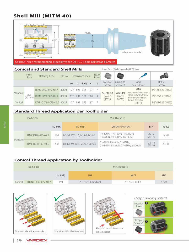
270
MIT
M
Conical and Standard Shell Mills Spare Parts ( Ordering code & EDP No.)
Insert Style Ordering Code EDP No. Dimensions (inch) No. of
Flutes
D1 D2 d(H7) H Z Location Screw
ClampingScrew x2
Torx+ Screwdriver
Holder Screw
Standard 1.575"
(40 mm)
RTMC D190-075-40L7 80623 1.77 1.93 0.75 1.97 7SLD4IP8A
(M4x0.7)(80533)
SCD4IP8(M4x0.7)(80622)
KIP8• Use the included Vardex Torx+ screwdriver only
• Recommended max. torque 10.6 lbfxin
(70231)
3/8"-24x1.25 (70223)
RTMC D230-100-40L9 80624 2.17 2.32 1.00 2.00 9 1/2"-20x1.5 (70224)
Conical RTMNC D190-075-40L7 80625 1.77 1.93 0.75 1.97 7 3/8"-24x1.25 (70223)
Coolant-Thru is recommended, especially when D2 > 0.7 x nominal thread diameter
Always mount all inserts on the same side!Side without identification marksSide with identification marks
2 Step Clamping System!
Da
Adaptor not included
D1≥Da
H
d(H7) D1D2
Shell Mill (MiTM 40)
ClampingScrew x2
Location Screw
Conical Thread Application by Toolholder
Toolholder Min. Thread Ø
D2 (inch) NPT NPTF BSPT
Conical RTMNC D190-075-40L7 1.93 2-11.5; 21⁄2-8 (and up) 2-11.5; 21⁄2-8; 3-8 2-6x11
Standard Thread Application per Toolholder
Toolholder Min. Thread Ø
D2 (inch) ISO (fine) UN/UNF/UNEF/UNS BSW BSP(G)
Standard
RTMC D190-075-40L7 1.93 M52x1; M55x1.5; M55x2; M55x3 17⁄8-12UN; 113⁄16-16UN; 113⁄16-20UN; 115⁄16-8UN; 17⁄8-10UNS; 17⁄8-14UNS
2¼ -12; 2¼ -16 1¾ -11
RTMC D230-100-40L9 2.32 M64x1; M64x1.5; M64x2; M65x3 21⁄4-8UN; 21⁄4-10UN; 21⁄4-12UN; 21⁄4-14UN; 21⁄4-16UN; 21⁄4-18UN; 21⁄4-20UN
2½ -12; 2½ -16 2¼ -11
2
1

271
MIT
M
Side without identification marks
Always mount all inserts on the same side!Side with identification marks
Coolant-Thru is recommended, especially when D2 > 0.7 x nominal thread diameter
D2
D1
D
LL1
D1
Clamping Screw
LocationScrew x2
2 Step Clamping System!
Standard Toolholders (MiTM 41)
* For external applications, inserts R41E... use for CNC program (D2+0.024")
Standard Thread Application by Toolholder
Toolholder Min. Thread Ø
D2*(inch)
ISO(coarse)
ISO(fine) UNC UN/UNF/UNEF/UNS BSW/BSF NPT NPTF
RTMC 100096-169B2 0.97 M30x3.5; M36x4 M28X3; M45x4 11⁄8-7; 13⁄8-6 11⁄8-8UN; 17⁄16-6UN 13⁄8-8BSF; 11⁄4-7BSW - -
RTMC 125118-169B3 1.18 M36x4; M42x4.5 M34X3; M34x3.5; M45x4 13⁄8-6 13⁄8-8UN; 17⁄16-6UN 13⁄8-8BSF; 13⁄4-7BSF;
11⁄2-6BSW - -
RTMC 125118-256B3 1.18 M36x4; M42x4.5 M34X3; M34x3.5;M45x4 13⁄8-6 13⁄8-8UN; 17⁄16-6UN 13⁄8-8BSF; 13⁄4-7BSF;
11⁄2-6BSW - -
RTMC 125141-169B5 1.42 M42x4.5; M48x5; M56x5.5; M64x6
M40x3; M40x3.5;M42x4; M70x6
13⁄4-5; 2-4.5;21⁄2-4 15⁄8-8UN; 15⁄8-6UN 15⁄8-8BSF; 13⁄4-7BSF;
17⁄8-6BSF 21⁄2-8 21⁄2-8
RTMC 125141-256B4 1.42 M42x4.5; M48x5; M56x5.5; M64x6
M40x3; M40x3.5;M42x4; M70x6
13⁄4-5; 2-4.5; 21⁄2-4 15⁄8-8UN; 15⁄8-6UN 15⁄8-8BSF; 13⁄4-7BSF;
17⁄8-6BSF 21⁄2-8 21⁄2-8
RTMC - for Standard Threads Spare Parts ( Ordering code & EDP No.)
Insert Style Ordering Code EDP No. Dimensions (inch)No. of Flutes
L L1 D D1 D2* Z Location Screw x2 Clamping Screw Torx+ Screwdriver
1.614"(41 mm)
RTMC 100096-169B2 80864 4.13 1.69 1.00 0.76 0.97 2
SLD4IP8A(M4x0.7)(80533)
SCD4IP8(M4x0.7)(80622)
KIP8• Use the included Vardex Torx+ screwdriver only
• Recommended max. torque 10.6 lbfxin
(70231)
RTMC 125118-169B3 80865 4.13 1.69 1.25 0.95 1.18 3
RTMC 125118-256B3 80866 5.00 2.56 1.25 0.95 1.18 3
RTMC 125141-169B5 80867 4.13 1.69 1.25 1.11 1.42 5
RTMC 125141-256B4 80868 4.98 2.56 1.25 1.11 1.42 4
1
2

272
MIT
M
H
Da
Adaptor not included
D1≥Da
D1d(H7)D2
Always mount all inserts on the same side!Side without identification marksSide with identification marks
Clamping Screw
LocationScrew x2
2 Step Clamping System!
* For external applications, inserts R41E... use for CNC program (D2+0.024")
Standard Shell Mill Spare Parts ( Ordering code & EDP No.)
Insert Style Ordering Code EPD No. Dimensions (inch) No. of Flutes
D1 D2* d(H7) H Z Location Screw x2 Clamping Screw Torx+ Screwdriver Holder
Screw
1.614"(41 mm)
RTMC D209-075-41B5 80869 1.77 2.09* 0.75 2.00 5 SLD4IP8A(M4x0.7)(80533)
SCD4IP8(M4x0.7)(80622)
KIP8• Use the included Vardex Torx+ screwdriver only
• Recommended max. torque 10.6 lbfxin
(70231)
3/8"-24x1.5 (70264)
RTMC D248-100-41B6 80870 2.17 2.48* 1.00 2.00 6 1/2"-20x1.5 (70224)
Coolant-Thru is recommended, especially when D2 > 0.7 x nominal thread diameter
Shell Mill (MiTM 41)
Standard Thread Application by Toolholder
Toolholder Min. Thread Ø
D2*(inch)
ISO(coarse)
ISO(fine) UNC UN/UNF/UNEF/UNS BSF NPT NPTF
RTMC D209-075-41B5 2.09* M64X6 M58x4;M70x6 21⁄2-4 23⁄8-6UN;
23⁄8-8UN 23⁄8-8;2½-6 21⁄2-8 21⁄2-8
RTMC D248-100-41B6 2.48* - M68x4;M70x6 3-4 2¾-6UN;
2¾-8UN 2¾-8;2¾-6 21⁄2-8 21⁄2-8
2
1

273
MIT
M
Grades
Grade Application Sample
VBX TiCN coated carbide grade.Excellent grade for steels and general use.
VTX TiAlN coated carbide grade.Ideal for Stainless Steels.
Recommended Grades, Cutting Speeds Vc [ft/min] and Feed f [inch/tooth]
Material Group Va
rdex
No.
Material
HardnessBrinell
HB
Vc [ft/min] Feed f[inch/tooth]
VBX VTX f
PSteel
1Unalloyed steel
Low carbon (C=0.1-0.25%) 125 328-689 295-590 .0040-.01382 Medium carbon (C=0.25-0.55%) 150 328-590 295-558 .0040-.01573 High Carbon (C=0.55-0.85%) 170 328-558 295-524 .0040-.01384
Low alloy steel(alloying elements≤5%)
Non hardened 180 295-197 295-508 .0040-.01575 Hardened 275 262-492 262-525 .0040-.01386 Hardened 350 230-459 230-492 .0040-.01187 High alloy steel
(alloying elements>5%) Annealed 200 197-426 230-377 .0040-.0138
8 Hardened 325 230-361 197-328 .0040-.00809
Cast steel Low alloy (alloying elements <5%) 200 328-558 328-558 .0040-.0118
10 High alloy (alloying elements >5%) 225 230-394 230-426 .0040-.0080
MStainless
Steel
11 Stainless steel Feritic
Non hardened 200 328-558 394-590 .0040-.011812 Hardened 330 328-558 394-590 .0040-.008013 Stainless steel
Austenitic Austenitic 180 230-460 328-459 .0040-.0118
14 Super Austenitic 200 230-460 328-459 .0040-.008015 Stainless steel
Cast Feritic Non hardened 200 230-460 328-459 .0040-.0118
16 Hardened 330 230-460 328-459 .0040-.008017 Stainless steel
Cast austenitic Austenitic 200 230-394 328-394 .0040-.0118
18 Hardened 330 230-394 328-394 .0040-.0080
KCast Iron
28 Malleable Cast iron
Ferritic (short chips) 130 197-426 328-394 .0020-.006329 Pearlitic (long chips) 230 197-394 262-328 .0016-.004030
Grey cast iron Low tensile strength 180 197-426 262-328 .0040-.0118
31 High tensile strength 260 197-328 262-328 .0040-.008032
Nodular SG iron Feritic 160 197-410 262-328 .0040-.0118
33 Pearlitic 260 164-295 197-295 .0040-.0080
N(K)Non-Ferrous
Metals
34 Aluminium alloys Wrought
Non aging 60 328-820 .0060-.021635 Aged 100 328-590 .0060-.019736
Aluminium alloys Cast 75 492-1312 .0060-.0197
37 Cast & aged 90 492-918 .0040-.015738 Aluminium alloys Cast Si 13-22% 130 262-492 .0060-.019739 Copper and
copper alloys Brass 90 394-689 328-565 .0060-.0197
40 Bronze and non leaded copper 100 394-689 328-565 .0040-.0157
S(M)Heat
ResistantMaterial
19
High temperaturealloys
Annealed (Iron based ) 200 66-148 66-131 .0040-.008020 Aged (Iron based) 280 66-98 66-98 .0016-.004021 Annealed (Nickel or Cobalt based) 250 49-66 49-66 .0016-.004022 Aged (Nickel or Cobalt based) 350 33-49 33-49 .0016-.004023
Titanium alloys Pure 99.5 Ti 400Rm 230-459 230-394 .0016-.0040
24 a+b alloys 1050Rm 66-164 66-164 .0016-.0040
H(K)Hardened Material
25
Extra hard steel Hardened & tempered
45-50HRc 49-148 49-148 .0024-.0047
26 51-55HRc 49-131 49-131 .0016-.0031

274
MIT
M

TMSDThread Mill for Deep Holes > Inserts
> Toolholders> Technical Data
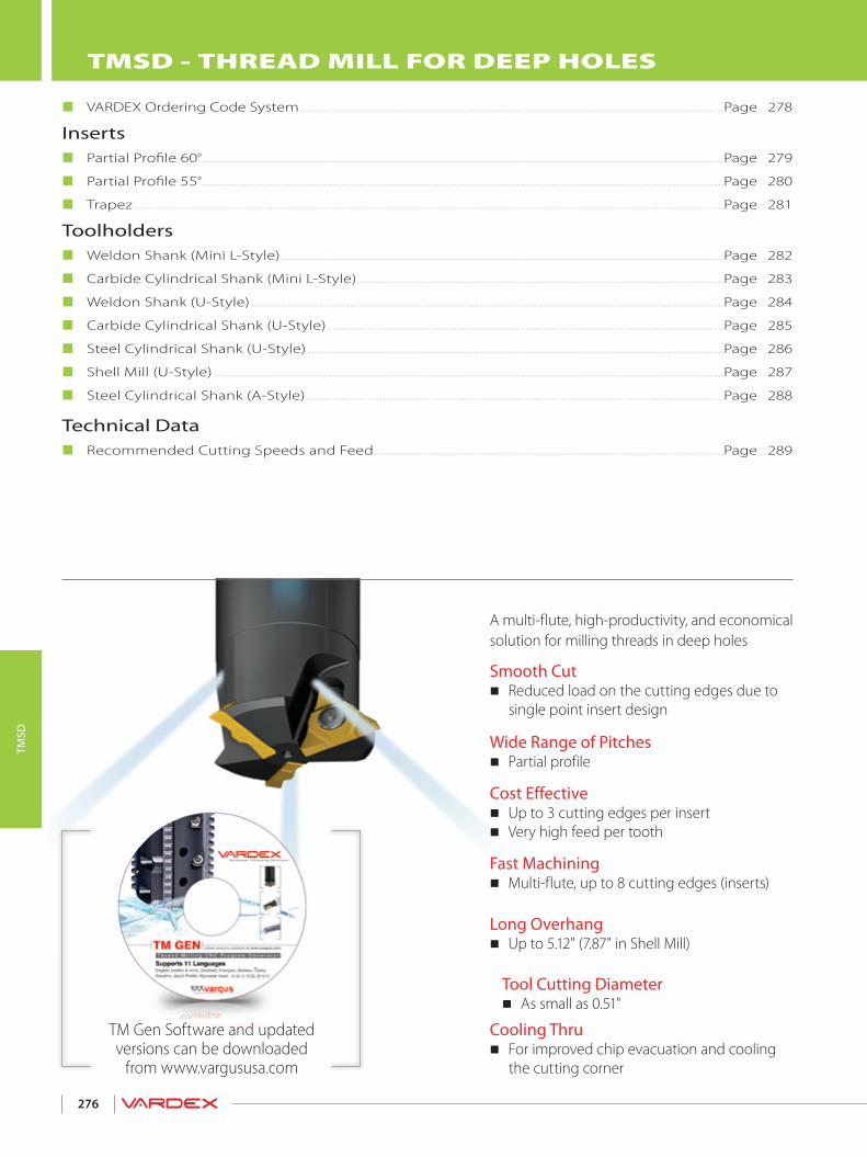
276
TMSD
TM Gen Software and updated versions can be downloaded
from www.vargususa.com
A multi-flute, high-productivity, and economical solution for milling threads in deep holes
Wide Range of Pitches Partial profile
Fast Machining Multi-flute, up to 8 cutting edges (inserts)
Cost Effective Up to 3 cutting edges per insert Very high feed per tooth
Smooth Cut Reduced load on the cutting edges due to single point insert design
Cooling Thru For improved chip evacuation and cooling the cutting corner
Long Overhang Up to 5.12" (7.87" in Shell Mill)
Tool Cutting Diameter As small as 0.51"
TMSD - THREAD MILL FOR DEEP HOLES
VARDEX Ordering Code System ...............................................................................................................................................Page 278
Inserts Partial Profile 60°................................................................................................................................................................................Page 279
Partial Profile 55°................................................................................................................................................................................Page 280
Trapez .......................................................................................................................................................................................................Page 281
Toolholders Weldon Shank (Mini L-Style) .....................................................................................................................................................Page 282
Carbide Cylindrical Shank (Mini L-Style) ...........................................................................................................................Page 283
Weldon Shank (U-Style) ...............................................................................................................................................................Page 284
Carbide Cylindrical Shank (U-Style) ......................................................................................................................................Page 285
Steel Cylindrical Shank (U-Style) ............................................................................................................................................Page 286
Shell Mill (U-Style) ............................................................................................................................................................................Page 287
Steel Cylindrical Shank (A-Style) .............................................................................................................................................Page 288
Technical Data Recommended Cutting Speeds and Feed ......................................................................................................................Page 289
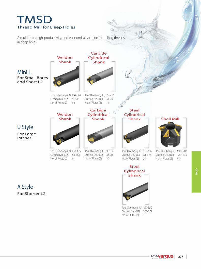
277
TMSD
A StyleFor Shorter L2
U StyleFor Large Pitches
Mini LFor Small Bores and Short L2
Shell Mill
Steel Cylindrical
Shank
Steel Cylindrical
Shank
Carbide Cylindrical
Shank
Carbide Cylindrical
Shank
Weldon Shank
Weldon Shank
TMSDThread Mill for Deep Holes
A multi-flute, high-productivity, and economical solution for milling threads in deep holes
Tool Overhang (L1) 1.14-1.65 Cutting Dia. (D2) .51-.70No. of Flutes (Z) 1-3
Tool Overhang (L1) 1.57-4.72 Cutting Dia. (D2) .58-1.66No. of Flutes (Z) 1-4
Tool Overhang (L1) .79-2.55 Cutting Dia. (D2) .51-.70No. of Flutes (Z) 1-3
Tool Overhang (L1) .98-3.15 Cutting Dia. (D2) .58-.81No. of Flutes (Z) 1-2
Tool Overhang (L1) 1.57-5.12 Cutting Dia. (D2) .91-1.44No. of Flutes (Z) 2-4
Tool Overhang (L1) Max. 7.87 Cutting Dia. (D2) 1.69-4.35No. of Flutes (Z) 4-8
Tool Overhang (L1) 1.97-5.12 Cutting Dia. (D2) 1.02-1.39No. of Flutes (Z) 3
Tool Cutting Diameter As small as 0.51"

IC
U -
A -
278
TMSD
TMSD Inserts
Vardex Ordering Code System
TMSD Toolholders
L -
A -
U -
3 - Type of InsertI - Internal
7 - Carbide GradeVBX, VTX
5 - Standard60° - Partial Profile 60°55° - Partial Profile 55°TR - Trapez DIN 103
6 - SystemTM
4 - PitchFull Profile - Pitch Range
mm tpi2.0-5.0 -
Partial Profile - Pitch Rangemm tpi
DADBDCDDDEDHDKDLDMDNDPDRDT
0.5-1.51.5-2.02.5-4.02.0-2.52.5-3.54.0-6.06.0-8.0
-2.5
1.0-2.01.5-3.0
-2.0-4.0
48-1616-1210-69-1210-76-44-3
11-710
24-1116-8
26-1412-6
2 - Insert Style1- Insert Size5L - IC5.0L mm2 - IC1/4”3 - IC3/8”4 - IC1/2”
VBX7
TM6
605
DB4
I3
U2
21
TM2
C1
TM1
23
42
S4
S3
C5
C4
0566
D1695
C7
- -
0688
2359
210
0506
37
U8
- - U11
2- System
TM
1- Shank Style
None - Steel C - Carbide Shank
3 - No. of Flutes
1- 4
5 - Cooling
C - Coolant
9 - Max. Tool Overhang
.79-5.12
6 - Shank Dia.
.375-1.50
7 - Shank Type
W - WeldonC - Cylindrical
8 - Cutting Dia.
.51-1.65
10 - Insert Size5L - IC5.0L mm2 - IC1/4”3 - IC3/8”4 - IC1/2”
11 - Insert Style
U AL
4 - Insert Type
S - Single Point
1- System
TM
2 - No. of Flutes
4-8
4 - Cooling
C - Coolant
5 - Cutting Dia.
1.69-4.35
6 - Drive Hole Dia.
.50, .75, 1.0, 1.5
7 - Insert Size
3 - IC3/8”4 - IC1/2”
8 - Insert Style
U
3 - Insert Type
S - Single Point
TMSD Shell Mill

��
�����
��
�����
��
�����
279
TMSD
U StyleInsert Size Pitch Ordering Code EDP No. Dimensions (inch)IC L inch mm tpi Internal VTX VBX r * Toolholder
1/4”U .43
0.5-1.5 48-16 2UIDA60 TM… 50305 50299 .002 TM.SC...2UCTM. SC…2U1.5-2.0 16-12 2UIDB60 TM… 50018 50008 .002
2.0-2.5 9-12 2UIDD60 TM… 50355 50352 .004 CTM2SC 056C068-235-2U2.5 10 2UIDM60 TM… 50296 50291 .004
2.5-4.0 10-6 2UIDC60 TM… 50033 50026 .006 TM.SC...2UCTM. SC…2U
3/8”U .631.5-2.0 16-12 3UIDB60 TM… 50040 50034 .002
TM.SC...3U2.5-3.5 10-7 3UIDE60 TM… 50044 50041 .0064.0-6.0 6-4 3UIDH60 TM… 50048 50045 .001
1/2”U .87 6.0-8.0 4-3 4UIDK60 TM… 50052 50049 .012 TM.SC D...4U
TMSD - Partial Profile 60°
60°
External
Internal
2UIDB60 TM…2UIDD60 TM…
L
r *
r *r *r *
LLL
ICICICICMini L Style U Style A Style
Internal
2UIDB60 TM…2UIDD60 TM…
* The indicated radius (r) refers to the insert nose radius only
Mini-L StyleFor Small Bores and Short L2
A StyleFor Shorter L2
U StyleFor Large Pitches
A StyleInsert Size Pitch Ordering Code EDP No. Dimensions (inch)IC L inch mm tpi Internal VTX VBX r * Toolholder
1/4”A .43 1.5-3.0 16-8 2AIDP60 TM… 50219 50200 .002 TM.SC...2A3/8”A .63 2.0-4.0 12-6 3AIDT60 TM… 50227 50226 .003 TM.SC...3A
Mini-LInsert Size Pitch Ordering Code EDP No. Dimensions (inch)IC L inch mm tpi Internal VTX VBX r * Toolholder
5.0L -0.5-1.5 48-16 5LIDA60 TM… 50264 50263 .002 TM.SC…5L
CTM. SC…5L1.0-2.0 24-11 5LIDN60 TM… 50267 50266 .002

55°
��
�����
��
�����
��
�����
��
�����
��
�����
��
�����
280
TMSD
External
Internal
L
r * r *
ICICMini L Style U Style
Internal
TMSD - Partial Profile 55°
* The indicated radius (r) refers to the insert nose radius only
Mini-L StyleFor Small Bores and Short L2
U StyleFor Large Pitches
Mini-L Insert Size Pitch Ordering Code EDP No. Dimensions (inch)
IC tpi Internal VTX VBX r* Toolholder
5.0L 26-14 5LIDR55 TM… 50269 50268 .004 TM.SC…5LCTM. SC…5L
U Style Insert Size Pitch Ordering Code EDP No. Dimensions (inch)
IC L inch tpi Internal VTX VBX r* Toolholder
1/4”U .4348-16 2UIDA55 TM… 50317 50309 .004
TM.SC...2UCTM. SC…2U16-12 2UIDB55 TM… 50055 50053 .003
11-7 2UIDL55 TM… 50061 50056 .010
3/8”U .6316-12 3UIDB55 TM… 50067 50062 .003
TM.SC...3U11-7 3UIDL55 TM… 50091 50068 .0096-4 3UIDH55 TM… 50148 50233 .011
1/2”U .87 4-3 4UIDK55 TM… 50190 50189 .020 TM.SC...4U

h
30°
281
TMSD
External
Internal
L
ICICDefined by: DIN 103Tolerance class: 7e/7H
Mini L Style U Style
U StyleInsert Size Pitch Ordering Code EDP No. ApplicationIC L inch mm Internal VTX VBX Internal Toolholder
1/4”U .43
3.02UI3TR-1 TM… 50383 50372 (TR22-TR30)x3
See pages 284-285
2UI3TR-2 TM… 50389 50386 (TR32-TR60)x3
4.02UI4TR-1 TM… 50396 50394 (TR20-TR28)x42UI4TR-2 TM… 50415 50399 (TR65-TR110)x4
5.02UI5TR-1 TM… 50428 50417 TR22x5; TR28x52UI5TR-2 TM… 50438 50431 TR24x5; TR26x5
Internal
TMSD - Trapez
Mini-L Insert Size Pitch Ordering Code EDP No. Application
IC mm Internal VTX VBX Internal Toolholder
5.0L 2.05LI2.0TR-1 TM… 50359 50207 TR16x2, TR20x2
See pages 282-2835LI2.0TR-2 TM… 50367 50361 TR18x2
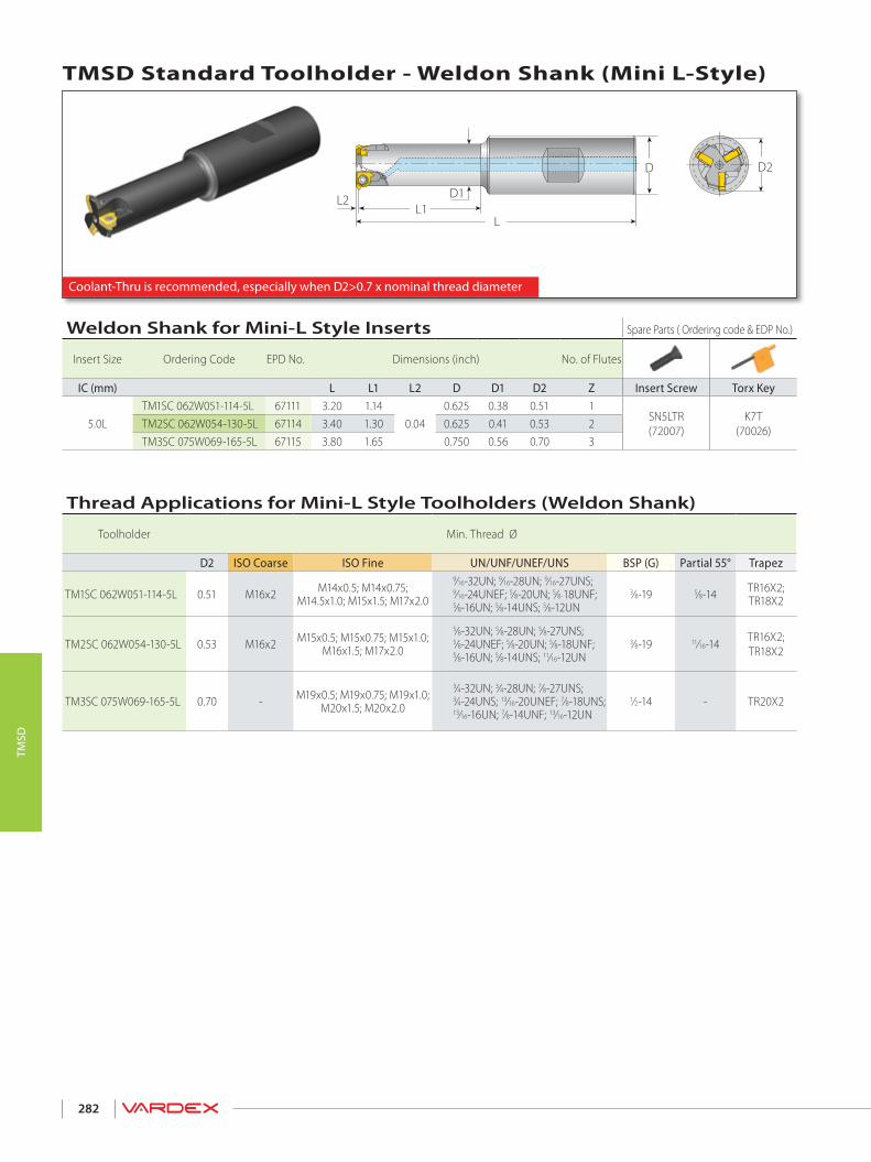
282
TMSD
Coolant-Thru is recommended, especially when D2>0.7 x nominal thread diameter
D2D
L
L2 D1L1
TMSD Standard Toolholder - Weldon Shank (Mini L-Style)
Thread Applications for Mini-L Style Toolholders (Weldon Shank)
Toolholder Min. Thread Ø
D2 ISO Coarse ISO Fine UN/UNF/UNEF/UNS BSP (G) Partial 55° Trapez
TM1SC 062W051-114-5L 0.51 M16x2 M14x0.5; M14x0.75; M14.5x1.0; M15x1.5; M17x2.0
9⁄16-32UN; 9⁄16-28UN; 9⁄16-27UNS;9⁄16-24UNEF; 5⁄8-20UN; 5⁄8-18UNF;5⁄8-16UN; 5⁄8-14UNS; 5⁄8-12UN
3⁄8-19 5⁄8-14 TR16X2; TR18X2
TM2SC 062W054-130-5L 0.53 M16x2 M15x0.5; M15x0.75; M15x1.0; M16x1.5; M17x2.0
5⁄8-32UN; 5⁄8-28UN; 5⁄8-27UNS;5⁄8-24UNEF; 5⁄8-20UN; 5⁄8-18UNF;5⁄8-16UN; 5⁄8-14UNS; 11⁄16-12UN
3⁄8-19 11⁄16-14 TR16X2;TR18X2
TM3SC 075W069-165-5L 0.70 - M19x0.5; M19x0.75; M19x1.0; M20x1.5; M20x2.0
3⁄4-32UN; 3⁄4-28UN; 7⁄8-27UNS;3⁄4-24UNS; 13⁄16-20UNEF; 7⁄8-18UNS;13⁄16-16UN; 7⁄8-14UNF; 13⁄16-12UN
1⁄2-14 - TR20X2
Weldon Shank for Mini-L Style Inserts Spare Parts ( Ordering code & EDP No.)
Insert Size Ordering Code EPD No. Dimensions (inch) No. of Flutes
IC (mm) L L1 L2 D D1 D2 Z Insert Screw Torx Key
5.0LTM1SC 062W051-114-5L 67111 3.20 1.14
0.040.625 0.38 0.51 1
SN5LTR(72007)
K7T(70026)TM2SC 062W054-130-5L 67114 3.40 1.30 0.625 0.41 0.53 2
TM3SC 075W069-165-5L 67115 3.80 1.65 0.750 0.56 0.70 3

283
TMSD
D2D
L
L2 L1 (max)
L3 (min)
Coolant-Thru is recommended, especially when D2>0.7 x nominal thread diameter
TMSD Standard Toolholder - Carbide Cylindrical Shank (Mini L-Style)
Thread Applications for Mini-L Style Toolholders (Carbide Cylindrical Shank)
Toolholder Min. Thread Ø
D2 ISO Coarse ISO Fine UN/UNF/UNEF/UNS BSP (G) Partial 55° Trapez
CTM1SC 037C051-169-5L 0.51 M16x2 M14x0.5; M14x0.75; M14.5x1.0; M15x1.5; M17x2.0
9⁄16-32UN; 9⁄16-28UN; 9⁄16-27UNS;9⁄16-24UNEF; 5⁄8-20UN; 5⁄8-18UNF;5⁄8-16UN; 5⁄8-14UNS; 5⁄8-12UN
3⁄8-19 5⁄8-14 TR16X2; TR18X2
CTM2SC 037C53-197-5L 0.53 M16x2 M15x0.5; M15x0.75; M15x1.0; M16x1.5; M17x2.0
5⁄8-32UN; 5⁄8-28UN; 5⁄8-27UNS;5⁄8-24UNEF; 5⁄8-20UN; 5⁄8-18UNF;5⁄8-16UN; 5⁄8-14UNS; 11⁄16-12UN
3⁄8-19 11⁄16-14 TR16X2;TR18X2
CTM3SC 056C069-255-5L 0.70 - M19x0.5; M19x0.75; M19x1.0; M20x1.5; M20x2.0
3⁄4-32UN; 3⁄4-28UN; 7⁄8-27UNS;3⁄4-24UNS; 13⁄16-20UNEF; 7⁄8-18UNS;13⁄16-16UN; 7⁄8-14UNF; 13⁄16-12UN
1⁄2-14 - TR20X2
Carbide Cylindrical Shank for Mini-L Style Inserts Spare Parts ( Ordering code & EDP No.)
Insert Size Ordering Code EDP No. Dimensions (inch) No. of Flutes
IC (mm) L L1 (max) L2 L3 (min) D D2 Z Insert Screw Torx Key
5.0LCTM1SC 037C051-169-5L 67118 4.30 1.69
0.040.79 0.375 0.51 1
SN5LTR(72007)
K7T(70026)CTM2SC 037C53-197-5L 67119 4.60 1.97 0.87 0.375 0.53 2
CTM3SC 056C069-255-5L 67120 5.20 2.56 1.18 0.5625 0.70 3
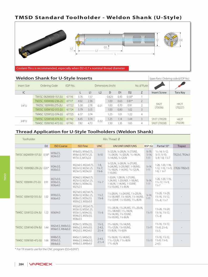
284
TMSD
Coolant-Thru is recommended, especially when D2>0.7 x nominal thread diameter
D2D
L
L2 D1L1
TMSD Standard Toolholder - Weldon Shank (U-Style)
* For TR inserts use for the CNC program (D2+0.010")
Thread Application for U-Style Toolholders (Weldon Shank)
Toolholder Min. Thread Ø
D2 ISO Coarse ISO Fine UNC UN/UNF/UNEF/UNS BSP (G) Partial 55° Trapez
TM1SC 062W059-157-2U 0.58* M18x2.5, M24x3.0
M16x0.5, M16x0.75, M16x1.0, M17x1.25, M17x1.5, M17x2.0
3⁄4-105⁄8-32UN, 5⁄8-28UN, 5⁄8-27UNS, 11⁄16-24UN, 11⁄16-20UN, 11⁄16-16UN, 3⁄4-14UNS, 3⁄4-12UN
3⁄8-19, 1⁄2-14, 1-11
11⁄16-14; 3⁄4-12;7⁄8-11; 3⁄4-10;7⁄8-9; 1-8; 11⁄8-7
TR22x3, TR24x3
TM2SC 100W082-236-2U 0.81* M24x3.0,M30x3.5
M22x0.5, M22x0.75, M22x1.0, M23x1.25, M23x1.5, M23x2.0
1-8, 11⁄8 -7, 13⁄8-6
7⁄8-32UN, 7⁄8-28UN, 7⁄8-27UNS, 7⁄8-24UNS, 7⁄8-20UNEF, 1-18UNS, 15⁄16-16UN, 1-14UNS, 15⁄16-12UN, 1-10UNS
3⁄4-14, 1-11
1-26, 1-20, 1-16, 1-12, 1-10, 11⁄8-9, 1-8, 1 1⁄8-7
(TR26-TR60x3)
TM2SC 100W90-275-2U 0.91M27x3.0, M30x3.5, M36x4.0
M24x0.5, M24x0.75, M25x1.0, M25x1.25, M26x1.5, M26x2.0, M27x2.5
11⁄8 -7
1-32UN, 1-28UN, 1-27UNS, 1-24UNS, 1-20UNEF, 1-18UNS, 1-16UN, 1-14UNS, 1-12UNF,11⁄8-10UNS, 11⁄8-8UN
3⁄4-14, 1-11
1-26, 1-20, 1-16, 11⁄16-12, 11⁄8-9, 11⁄8-7
-
TM3SC 100W102-315-2U 1.02 M30x3.5, M36x4.0
M27x0.5, M27x0.75, M28x1.0, M28x1.25, M28x1.5, M29x2.0, M30x2.5, M30x3.0
11⁄4-7,13⁄8-6
11⁄8-28UN, 11⁄8-24UNS, 11⁄8-20UN, 11⁄8-18UNEF, 11⁄8-16UN, 11⁄8-14UNS, 11⁄8-12UNF, 11⁄4-10UNS, 13⁄16-8UN
7⁄8-14, 1-11
11⁄8-26, 11⁄8-20, 13⁄8-16, 13⁄8-12, 13⁄16-8, 11⁄4-7
-
TM4SC 125W122-374-2U 1.22 M36X4.0
M32x0.5, M32x0.75, M33x1.0, M33x1.25, M33x1.5, M34x2.0, M34x2.5, M35x3.0, M36x3.5
11⁄2-6
15⁄16-28UN, 13⁄8-24UNS, 15⁄16-20UN, 15⁄16-18UNEF, 15⁄16-16UN,13⁄8-14UNS, 13⁄8-12UNF,13⁄8-10UNS, 13⁄8-8UN
11⁄8-1113⁄8-26, 13⁄8-20, 13⁄8-16, 13⁄8-12, 17⁄16-8
-
TM3SC 125W143-374-3U 1.44 M42x4.5, M48x5.0,M56x5.5, M64x6.0
M39x1.5, M39x2.0,M40x2.5, M41x3.0,M42x3.5, M42x4.0
13⁄4-5,2-4.5,21⁄2-4
19⁄16-16UN, 15⁄8-14UNS,19⁄16-12UN, 15⁄8-10UNS,15⁄8-8UN, 15⁄8-6UN
11⁄4-1115⁄8-16, 15⁄8-12,15⁄8-8, 21⁄4-6,13⁄4-5
-
TM4SC 150W165-472-3U 1.66M48x5.0,M56x5.5,M64x6.0
M45x1.5, M45x2.0,M46x2.5, M48x3.0,M48x3.5, M48x4.0
2-4.5,21/2-4
13⁄4-16UN, 13⁄4-14UNS,113⁄16-12UN, 113⁄16-8UN115⁄16-6UN
11⁄2-1117⁄8-16, 17⁄8-12,17⁄8-8, 17⁄8-6,2-4.5
-
Weldon Shank for U-Style Inserts Spare Parts ( Ordering code & EDP No.)
Insert Size Ordering Code EDP No. Dimensions (inch) No. of Flutes
IC L L1 L2 D D1 D2 Z Insert Screw Torx Key
1/4”U
TM1SC 062W059-157-2U 67116 3.76 1.57
0.21
0.625 0.43 0.58* 1
SN2T(70036)
HK2T(70227)
TM2SC 100W082-236-2U 67117 4.92 2.36 1.00 0.63 0.81* 2TM2SC 100W90-275-2U 67722 5.38 2.76 1.00 0.70 0.91 2TM3SC 100W102-315-2U 67724 5.79 3.15 1.00 0.80 1.02 3
TM4SC 125W122-374-2U 67725 6.37 3.74 1.25 1.01 1.22 4
3/8”UTM3SC 125W143-374-3U 67742 6.45 3.74
0.321.25 1.14 1.44 3 SA3T (70028) HK3T
(70228)TM4SC 150W165-472-3U 67743 7.82 4.72 1.50 1.35 1.65 4 SN3T (70038)

285
TMSD
D2D
L
L2L1 (max)
L3 (min)
Coolant-Thru is recommended, especially when D2>0.7 x nominal thread diameter
TMSD Standard Toolholder - Carbide Cylindrical Shank (U-Style)
* For TR inserts use for CNC program (D2+0.010")* * To be used only with inserts 2UIDD60TM... or 2UIDM60TM... For insert 2UIDD60 TM... use for CNC program (D2+0.028")
Thread Applications for U-Style Toolholder (Carbide Cylindrical Shank)
Toolholder Min. Thread Ø
D2 ISO Coarse ISO Fine UNC UN/UNF/UNEF/UNS BSP (G) Partial 55° Trapez
CTM1SC 031C059-157-2U 0.58*
M18x2.5, M24x3.0, M30x3.5, M36x4.0
M16x0.5, M16x0.75, M16x1.0, M17x1.25, M17x1.5, M17x2.0
3⁄4-10, 7⁄8-9, 1-8, 11⁄8-7, 13⁄8-6
5⁄8-32UN, 5⁄8-28UN, 5⁄8-27UNS, 11⁄16-24UNEF, 11⁄16-20UN, 11⁄16-16UN, 3⁄4-14UNS, 11⁄16-12UN
1⁄2-14, 1-11
11⁄16-26, 11⁄16-20, 11⁄16-16, 11⁄16-14, 3⁄4-12, 7⁄8-11, 3⁄4-10, 7⁄8-9, 1-8, 11⁄8-7
TR22x3, TR24x3, TR20x4, TR22x5, TR24x5, TR26x5, TR28x5
CTM1SC 043C061-235-2U 0.60* M18x2.5, M24x3.0
M16x0.5, M16x0.75, M16x1.0, M17x1.25, M17x1.5, M17x2.0
3⁄4-10, 7⁄8-9, 1-8
5⁄8-32UN, 5⁄8-28UN, 5⁄8-27UNS, 11⁄16-24UNEF, 11⁄16-20UN, 11⁄16-16UN, 3⁄4-14UNS, 11⁄16-12UN
1⁄2-14, 1-11
11⁄16-26, 11⁄16-20, 11⁄16-16, 11⁄16-14, 3⁄4-12, 7⁄8-11, 3⁄4-10, 7⁄8-9
TR22x3, TR24x3
CTM2SC 056C068-235-2U 0.68** M20x2.5, M22x2.5 M21x2.0 7⁄8-9 7⁄8-10UNS, 13⁄16-12UN - - -
CTM2SC 056C082-256-2U 0.81*M24x3.0, M30x3.5, M36x4.0
M22x0.5, M22x0.75, M22x1.0, M23x1.25, M23x1.5, M23x2.0
1-8, 11⁄8-7, 13⁄8-6
7⁄8-32UN, 7⁄8-28UN, 7⁄8-27UNS, 7⁄8-24UNS, 7⁄8-20UNEF, 1-18UNS, 15⁄16-16UN, 1-14UNS, 15⁄16-12UN, 1-10UNS
3⁄4-14, 1-11
1-26, 1-20, 1-16, 1-12, 1-10, 11⁄8-9, 1-8, 11⁄8-7
(TR26-TR60)x3, TR28x4,(TR65-TR110)x4, TR28x5
CTM2SC 062C082-315-2U 0.81* M24x3.0, M30x3.5
M22x0.5, M22x0.75, M22x1.0, M23x1.25, M23x1.5, M23x2.0
1-8, 11⁄8-7, 13⁄8-6
7⁄8-32UN, 7⁄8-28UN, 7⁄8-27UNS, 7⁄8-24UNS, 7⁄8-20UNEF, 1-18UNS, 15⁄16-16UN, 1-14UNS, 15⁄16-12UN, 1-10UNS
3⁄4-14, 1-11
1-26, 1-20, 1-16, 1-12, 1-10, 11⁄8-9, 1-8, 11⁄8-7
(TR26-TR60)x3
Carbide Cylindrical Shank for U-Style Inserts Spare Parts ( Ordering code & EDP No.)
Insert Size Ordering Code EDP No. Dimensions (inch) No. of Flutes
IC L L1 (max) L2 L3 (min) D D2 Z Insert Screw Torx Key
1/4”U
CTM1SC 031C059-157-2U 67121 4.30 1.57 0.21 0.65 0.3125 0.58* 1
SN2T(70036)
HK2T(70227)
CTM1SC 043C061-235-2U 67123 4.72 2.36 0.21 0.98 0.4375 0.58* 1CTM2SC 056C068-235-2U** 67125 5.35 2.56 0.13 1.15 0.5625 0.68** 2CTM2SC 056C082-256-2U 67122 5.38 2.56 0.21 1.15 0.5625 0.81* 2CTM2SC 062C082-315-2U 67124 5.30 3.15 0.21 1.28 0.6250 0.81* 2

�������������������������������������������� ������������������������������ ��������������������������������������������������������������� �������������
286
TMSD
TMSD Standard Toolholder - Steel Cylindrical Shank (U-Style)
Thread Application for U-Style Toolholders (Steel Cylindrical Shank)
Toolholder Min. Thread Ø
D2 ISO Coarse ISO Fine UNC UN/UNF/UNEF/UNS BSP (G) Partial 55°
TM2SC 062C090-300-2U 0.91 M27x3.0, M30x3.5, M36x4.0
M24x0.5, M25x0.75, M25x1.0, M25x1.25, M26x1.5, M26x2.0, M27x2.5
11⁄8-7
1-32UN, 1-28UN, 1-27UN, 1-24UNS, 1-20UNEF, 1-18UNS, 1-16UN, 1-14UNS, 11⁄16-12UN, 11⁄8-10UNS, 11⁄8-8UN
3⁄4-14, 1-11
1-26, 1-20, 11⁄8-16, 11⁄8-12,11⁄8-9, 11⁄8-7
TM3SC 075C102-415-2U 1.02 M30x3.5, M36x4.0
M27x0.5, M27x0.75, M28x1.0, M28x1.25, M28x1.5, M29x2.0, M30x2.5, M30x3.0
11⁄4-7,13⁄8-6
11⁄8-28UN, 11⁄8-24UNS,11⁄8-20UN, 11⁄818UNEF, 11⁄8-16UN, 11⁄8-14UNS, 11⁄8-12UNF, 13⁄8-10UNS, 17⁄16-8UN
7⁄8-14, 1-11
11⁄8-26, 11⁄8-20,13⁄16-16, 13⁄16-12,13⁄16-8, 11⁄4-7
TM4SC 100C122-452-2U 1.22 M36x4.0
M32x0.5, M32x0.75, M33x1.0, M33x1.25, M33x1.5, M34x2.0, M34x2.5, M35x3.0, M36x3.5
11⁄2-6
15⁄16-28UN, 11⁄2-24UNS, 11⁄2-20UN, 11⁄218UNEF, 13⁄8-16UN, 13⁄8-14UNS, 13⁄8-12UNF, 13⁄8-10UNS, 17⁄16-8UN
11⁄8-1115⁄16-26, 15⁄16-20,13⁄8-16, 13⁄8-12, 17⁄16-8
TM3SC 100C143-512-3U 1.44M42.5x4.5, M48x5.0, M56x5.5, M64x6.0
M39x1.5, M40x2.5, M41x3.0, M42x3.5, M42x4.0
13⁄4-5, 2-4.5,21⁄2-4
19⁄16-16UN, 15⁄8-14UNS,19⁄16-12UN, 15⁄8-10UNS,15⁄8-8UN, 15⁄8-6UN
11⁄4-11 15⁄8-16, 15⁄8-12,15⁄8-8, 21⁄4-6, 13⁄4-5
Steel Cylindrical Shank for U-Style Inserts Spare Parts ( Ordering code & EDP No.)
Insert Size Ordering Code EDP No. Dimensions (inch) No. of Flutes
IC L L1 (max) L2 L3 (min) L4 D D1 D2 Z Insert Screw Torx Key
1/4”UTM2SC 062C090-300-2U 67744 5.60 3.00 0.21 1.35 2.16 0.625 0.70 0.91 2
SN2T(70036)
HK2T(70227)TM3SC 075C102-415-2U 67745 7.20 4.15 0.21 1.57 - 0.75 0.75 1.02 3
TM4SC 100C122-452-2U 67746 7.70 4.52 0.21 1.80 - 1.00 1.00 1.22 43/8”U TM3SC 100C143-512-3U 67747 8.35 5.12 0.31 1.80 3.08 1.00 1.14 1.44 3 SA3T (70028) HK3T (70228)
��
���
���������
�� ����������
��
Coolant-Thru is recommended, especially when D2>0.7 x nominal thread diameter

TMSD - Shell Mill (U-Style)TMSD - Shell Mill (U-Style)
287
TMSD
D1≥Da
d (H7) D1
H
D2
L2
Adaptor not included
Da
Coolant-Thru is recommended, especially when D2>0.7 x nominal thread diameter
TMSD - Shell Mill (U-Style)
Thread Application U-Style Shell Mill
Toolholder Min. Thread Ø
D2 ISO Coarse ISO Fine UNC UN/UNF/UNEF/UNS BSP (G) Partial 55°
TM4SC D169-050-3U 1.69 M56x5.5,M64x6.0,
M45x1.5, M48x2.0, M48x3.0, M48x4.0
2-4.5,21⁄2 - 4
113⁄16-16UN, 17⁄8-14UNS, 113⁄1612UN, 17⁄8-10UNS, 17⁄8-8UN, 115/16-6UN 11⁄2 - 11 17⁄8-16, 17⁄8-12, 17⁄8-8,
21⁄8-6, 2-4.5, 21⁄4-4
TM5SC D208-075-3U 2.09 M64x6.0 M55x1.5, M56x2.0, M58x3.0,M58x4.0 21⁄2 - 4 21⁄4-16UN, 21⁄4-14UNS, 21⁄4-12UN,
21⁄4-10UNS, 21⁄4-8UN, 23⁄8-6UN 2 - 11 21⁄4-16, 21⁄4-12, 23⁄8-8, 23⁄8-6, 3-5, 31⁄2-4.5
TM6SC D346-100-4U 3.47 - M95x6.0, M125x8 33⁄4 - 4 - 31⁄2 - 11 41⁄4-4, 4-3TM7SC D435-150-4U 4.35 - M120x6.0, M125x8 - 43⁄4-4UN - -
Shell Mill for U-style Inserts Spare Parts ( Ordering code & EDP No.)
Insert Size Ordering Code EDP No. Dimensions (inch) No. of Flutes
IC D1 D2 d(H7) H L2 Z InsertScrew Torx Key Holder Screw
3/8”UTM4SC D169-050-3U 67750 1.38 1.69 0.50 1.58 0.31 4 SN3T
(70038)HK3T
(70228)1/4-28x1.25 (70222)
TM5SC D208-075-3U 67751 1.77 2.09 0.75 1.58 0.31 5 3/8-24x1.25 (70223)
1/2”UTM6SC D346-100-4U 67752 2.99 3.47 1.00 2.00 0.39 6 SA4T
(70032)HK4T
(70241)1/2-20x1.50 (70224)
TM7SC D435-150-4U 67761 3.83 3.86 1.50 2.17 0.39 8 3/4-16x1.75 (70226)

�������������������������������������������� ������������������������������ ��������������������������������������������������������������� �������������
288
TMSD
TMSD Standard Toolholder - Steel Cylindrical Shank (A-Style)
Thread Application for A-Style Toolholders (Steel Cylindrical Shank)
Toolholder Min. Thread Ø
D2 ISO Coarse ISO Fine UNC UN/UNF/UNEF/UNS BSP (G)
TM3SC 075C102-415-2A 1.02 - M28x1.5, M29x2.0,M30x2.5, M30x3.0 - 11⁄8-16UN, 11⁄8-14UNS, 13⁄16-12UN,
11⁄4-10UNS, 13⁄16-8UN -
TM3SC 100C138-512-3A 1.39 - M38x2.0, M39x2.5,M39x3.0, M40x4.0 - 19⁄16-12UN, 15⁄8-10UNS, 15⁄8-8UN,
15⁄8-6UN -
Steel Cylindrical Shank for A-Style Inserts Spare Parts ( Ordering code & EDP No.)
Insert Size Ordering Code EDP No. Dimensions (inch) No. of Flutes
IC L L1 (max) L2 L3 (min) L4 D D1 D2 Z Insert Screw Torx Key
1/4”A TM3SC 075C102-415-2A 67748 7.20 4.15 0.12 1.57 - 0.75 0.75 1.02 3 SN2T (70036) HK2T (70227)3/8”A TM3SC 100C138-512-3A 67749 8.35 5.12 0.16 1.80 3.08 1.00 1.11 1.39 3 SA3T (70028) HK3T (70228)
Coolant-Thru is recommended, especially when D2>0.7 x nominal thread diameter
L3 (min)L1 (max)L2
L
D D2
L4
D1

289
TMSD
Grade Application
VBX TiCN coated carbide grade.Excellent grade for steels and general use.
VTX TiAlN coated carbide grade.Ideal for Stainless Steels.
Mini-L StyleA Style
* When using a Shell Mill holder, Feed can be increased by 50%
U StyleGrades
Recommended Grades, Cutting Speeds Vc [ft/min] and Feed f [inch/tooth]
Material Group Va
rdex
No.
MaterialHardness Brinell HB
Vc [ft/min] Feed* f [inch/tooth] byCutting Dia. (D2)
VBX VTX 0.51-0.91 0.94-1.65 Shell Mill
PSteel
1Unalloyed steel
Low carbon (C=0.1-0.25%) 125 328 - 689 295 - 590 0.0079 - 0.0126 0.0118 - 0.0197 0.0118 - 0.02952 Medium carbon (C=0.25-0.55%) 150 328 - 590 295 - 558 0.0079 - 0.0126 0.0118 - 0.0197 0.0118 - 0.02953 High Carbon (C=0.55-0.85%) 170 328 - 558 295 - 525 0.0059 - 0.0091 0.0098 - 0.0138 0.0098 - 0.02054
Low alloy steel(alloying elements≤5%)
Non hardened 180 197 - 295 295 - 508 0.0067 - 0.011 0.011 - 0.0177 0.011 - 0.02645 Hardened 275 262 - 492 262 - 525 0.0059 - 0.011 0.0098 - 0.0177 0.0098 - 0.02646 Hardened 350 230 - 459 230 - 492 0.0059 - 0.0098 0.0098 - 0.0157 0.0098 - 0.02367 High alloy steel
(alloying elements>5%) Annealed 200 197 - 426 230 - 377 0.0059 - 0.0087 0.0079 - 0.0118 0.0079 - 0.0177
8 Hardened 325 230 - 361 197 - 328 0.0051 - 0.0083 0.0071 - 0.0118 0.0071 - 0.01779
Cast steel Low alloy (alloying elements<5%) 200 328 - 558 328 - 558 0.0059 - 0.0087 0.0079 - 0.0118 0.0079 - 0.0177
10 High alloy (alloying elements >5%) 225 230 - 394 230 - 426 0.0047 - 0.0087 0.0067 - 0.0118 0.0067 - 0.0177
MStainless
Steel
11 Stainless steel Feritic
Non hardened 200 328 - 558 394 - 590 0.0059 - 0.0087 0.0087 - 0.0134 0.0087 - 0.019712 Hardened 330 328 - 558 394 - 590 0.0063 - 0.0091 0.0083 - 0.0126 0.0083 - 0.018913 Stainless steel
Austenitic Austenitic 180 230 - 459 328 - 459 0.0059 - 0.0098 0.0098 - 0.0157 0.0098 - 0.0236
14 Super Austenitic 200 230 - 459 328 - 459 0.0047 - 0.0079 0.0067 - 0.0102 0.0067 - 0.015415 Stainless steel
Cast Feritic Non hardened 200 230 - 459 328 - 459 0.0063 - 0.0094 0.0098 - 0.0146 0.0098 - 0.0217
16 Hardened 330 230 - 459 328 - 459 0.0047 - 0.0079 0.0067 - 0.0102 0.0067 - 0.015417 Stainless steel
Cast austenitic Austenitic 200 230 - 394 328 - 394 0.0059 - 0.0087 0.0079 - 0.0118 0.0079 - 0.0177
18 Hardened 330 230 - 394 328 - 394 0.0047 - 0.0079 0.0067 - 0.0102 0.0067 - 0.0154
KCast Iron
28 Malleable Cast iron
Ferritic (short chips) 130 197 - 426 328 - 394 0.0063 - 0.0094 0.0098 - 0.0146 0.0098 - 0.021729 Pearlitic (long chips) 230 197 - 394 262 - 328 0.0059 - 0.0087 0.0079 - 0.0118 0.0079 - 0.017730
Grey cast iron Low tensile strength 180 197 - 426 262 - 328 0.0059 - 0.0087 0.0087 - 0.0134 0.0087 - 0.0197
31 High tensile strength 260 197 - 328 262 - 328 0.0059 - 0.0087 0.0079 - 0.0118 0.0079 - 0.017732
Nodular SG iron Feritic 160 197 - 410 262 - 328 0.0039 - 0.0079 0.0059 - 0.0098 0.0059 - 0.0146
33 Pearlitic 260 164 - 295 197 - 295 0.0059 - 0.0087 0.0079 - 0.0118 0.0079 - 0.0177
N(K)Non-Ferrous
Metals
34 Aluminium alloys Wrought
Non aging 60 328 - 820 0.0118 - 0.0197 0.0236 - 0.0394 0.0236 - 0.059135 Aged 100 328 - 590 0.011 - 0.0197 0.0197 - 0.0354 0.0197 - 0.047236
Aluminium alloys Cast 75 492 - 1,312 0.011 - 0.0197 0.0197 - 0.0354 0.0197 - 0.0472
37 Cast & aged 90 492 - 918 0.0098 - 0.0157 0.0157 - 0.0236 0.0157 - 0.035438 Aluminium alloys Cast Si 13-22% 130 262 - 492 0.011 - 0.0197 0.0197 - 0.0354 0.0197 - 0.047239 Copper and
Copper alloys Brass 90 394 - 689 328 - 656 0.0118 - 0.0197 0.0236 - 0.0394 0.0236 - 0.0591
40 Bronze and non leaded copper 100 394 - 689 328 - 656 0.011 - 0.0197 0.0197 - 0.0354 0.0197 - 0.0472
S(M)Heat
Resistant Material
19
High temperaturealloys
Annealed (Iron based ) 200 66 - 148 66 - 131 0.0035 - 0.0059 0.0047 - 0.0087 0.0047 - 0.01320 Aged (Iron based) 280 66 - 98 66 - 98 0.0028 - 0.0051 0.0039 - 0.0079 0.0039 - 0.011821 Annealed (Nickel or Cobalt based) 250 49 - 66 49 - 66 0.0031 - 0.0059 0.0031 - 0.0079 0.0031 - 0.011822 Aged (Nickel or Cobalt based) 350 33 - 49 33 - 49 0.0031 - 0.0059 0.0031 - 0.0079 0.0031 - 0.011823
Titanium alloys Pure 99.5 Ti 400Rm 230 - 459 230 - 394 0.0028 - 0.0051 0.0039 - 0.0079 0.0039 - 0.0118
24 α+β alloys 1050Rm 66 - 164 66 - 164 0.0028 - 0.0051 0.0039 - 0.0079 0.0039 - 0.0118
H(K)Hardened Material
25
Extra hard steel Hardened & tempered
45-50HRc 49 - 148 49 - 148 0.002 - 0.0047 0.002 - 0.0071 0.002 - 0.0106
26 51-55HRc 49 - 131 49 - 131 0.002 - 0.0047 0.002 - 0.0071 0.002 - 0.0106

290
TMSD

TM SolidSolid Carbide Thread Milling Tools
> Tools> Technical Data
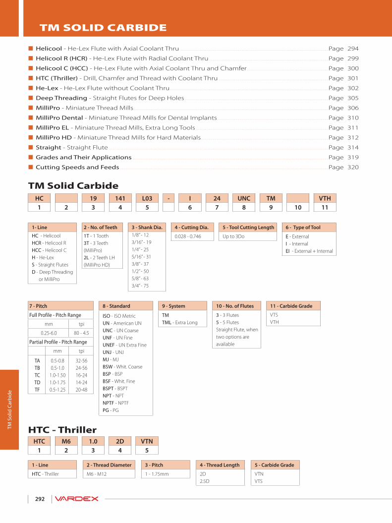
292
TM S
olid
Car
bide
TM Solid Carbide
Helicool - He-Lex Flute with Axial Coolant Thru ...............................................................................................................Page 294
Helicool R (HCR) - He-Lex Flute with Radial Coolant Thru .........................................................................................Page 299
Helicool C (HCC) - He-Lex Flute with Axial Coolant Thru and Chamfer .............................................................Page 300
HTC (Thriller) - Drill, Chamfer and Thread with Coolant Thru ..................................................................................Page 301
He-Lex - He-Lex Flute without Coolant Thru ......................................................................................................................Page 302
Deep Threading - Straight Flutes for Deep Holes ...........................................................................................................Page 305
MilliPro - Miniature Thread Mills .................................................................................................................................................Page 306
MilliPro Dental - Miniature Thread Mills for Dental Implants ...................................................................................Page 310
MilliPro EL - Miniature Thread Mills, Extra Long Tools ...................................................................................................Page 311
MilliPro HD - Miniature Thread Mills for Hard Materials ...............................................................................................Page 312
Straight - Straight Flute ....................................................................................................................................................................Page 314
Grades and Their Applications ..................................................................................................................................................Page 319
Cutting Speeds and Feeds ............................................................................................................................................................Page 320
TM SOLID CARBIDE
HC1
HTC1
2
M62
193
1.03
1414
2D4
L035
VTN5
- I6
247
UNC8
TM9 10
VTH11
1- Line
HC - HelicoolHCR - Helicool RHCC - Helicool CH - He-LexS - Straight Flutes D - Deep Threading or MilliPro
2 - No. of Teeth
1T - 1 Tooth3T - 3 Teeth(MilliPro)2L - 2 Teeth LH(MilliPro HD)
3 - Shank Dia.1/8” - 123/16” - 191/4” - 255/16” - 313/8” - 371/2” - 505/8” - 633/4” - 75
8 - Standard
ISO - ISO MetricUN - American UNUNC - UN CoarseUNF - UN FineUNEF - UN Extra FineUNJ - UNJMJ - MJBSW - Whit. CoarseBSP - BSP BSF - Whit. FineBSPT - BSPTNPT - NPTNPTF - NPTFPG - PG
4 - Cutting Dia.
0.028 - 0.746
1 - Line
HTC - Thriller
3 - Pitch
1 - 1.75mm
4 - Thread Length
2D2.5D
5 - Carbide Grade
VTNVTS
2 - Thread Diameter
M6 - M12
9 - System
TMTML - Extra Long
6 - Type of Tool
E - ExternalI - InternalEI - External + Internal
11 - Carbide Grade
VTSVTH
5 - Tool Cutting Length
Up to 3Do
10 - No. of Flutes
3 - 3 Flutes5 - 5 FlutesStraight Flute, when two options are available
7 - Pitch
Full Profile - Pitch Range
mm tpi
0.25-6.0 80 - 4.5
Partial Profile - Pitch Range
mm tpi
TATBTCTDTF
0.5-0.80.5-1.0
1.0-1.501.0-1.750.5-1.25
32-5624-5616-2414-2420-48
HTC - Thriller

293
TM S
olid
Car
bide
Up to 62 HRc
From M6x1.0From M3x0.5 (No.10-32UNF)
From No.10-32UNFFrom No.10-32UNF
From M4.5x0.75 (No.8-36UNF)From M3x0.5 (No.10-32UNF)
From M1.0x0.25 (0-80UNF)
From M1.6x0.35 (1-72UNF)
MilliPro HD
Full Profile
Partial Profile
MilliPro &MilliPro EL
He-Lex HTC
Helicool-C (HCC)
Helicool
Deep Threading
Helicool-R (HCR)
Straight Flutes
MilliPro
MilliPro Dental
A Tool for EVERY Thread Milling Job!
Up to 62 HRc
From M1.6x0.35 (1-72UNF)From M1.6x0.35 (1-72UNF)
MilliPro HD
MilliPro &MilliPro &MilliPro ELMilliPro EL
Long Thread
Drill, Thread and Chamfer
Helicool and Chamfer
Heavy Duty
Economical Tool
Radial Coolant
Normal Use
Miniature Threads
Up to 3XDo

American UNL
L1
D
D2
Le
Le
L1
D2
1/4P
1/8P
60º
Helicool
294
Hel
icoo
l
External
Internal
Defined by: ANSI B1.1:74Tolerance class: 2B
Internal
HelicoolAmerican UN
Maximum thread length = L1 - Pitch 4
*Bore Diameter applies to smallest thread Dia.
Helical Flutes with Thru-Hole Coolant 2 x Do (L1 ≤ 2 x Thread Diameter)
Thread Pitch Ordering Code EDP No. Dimensions inch No. of Flutes Teeth Bore Dia.*UNC UNF UNEF tpi Internal VTH D D2 L Le L1 Z Zt inch
No.10-32 No.12-3/8”x32 32 HC19150L03-I32UNF TM... 80291 3/16 .150 1.772 .375 .391 3 12 .157 No.12-3/8”x32 32 HC25173L04-I32UNEF TM... 80292 1/4 .173 2.244 .438 .453 3 14 .185 No.12; 1/4”x28 7/16"; 1/2"x28 28 HC25169L04-I28UNF TM... 80293 1/4 .169 2.244 .429 .446 3 12 .181 1/4"x28 7/16"; 1/2"x28 28 HC25203L05-I28UNF TM... 80294 1/4 .203 2.244 .500 .518 3 14 .216 7/16"; 1/2"x28 28 HC37371L08-I28UNEF TM... 80295 3/8 .371 2.874 .857 .875 3 24 .401No.10-24 5/16"; 3/8"x24 9/16"-11/16"x24 24 HC19141L04-I24UNC TM... 80296 3/16 .141 1.772 .375 .396 3 9 .150No.12-24 5/16"; 3/8"x24 9/16"-11/16"x24 24 HC25163L04-I24UNC TM... 80297 1/4 .163 2.244 .417 .437 3 10 .177 5/16"; 3/8"x24 9/16"-11/16"x24 24 HC31263L06-I24UNF TM... 80298 5/16 .263 2.402 .625 .646 3 15 .272 3/8"x24 9/16"-11/16"x24 24 HC37323L07-I24UNF TM... 80299 3/8 .323 2.874 .750 .771 3 18 .335 9/16"-11/16"x24 24 HC50496L11-I24UNEF TM... 80300 1/2 .496 3.150 1.125 1.145 4 27 .5201/4"x20 7/16"; 1/2"x20 3/4"-1"x20 20 HC25192L05-I20UNC TM... 80301 1/4 .192 2.244 .500 .525 3 10 .201 7/16"; 1/2"x20 3/4"-1"x20 20 HC37362L08-I20UNF TM... 80302 3/8 .362 2.874 .850 .875 3 17 .390 1/2"x20 3/4"-1"x20 20 HC50437L10-I20UNF TM... 80303 1/2 .437 3.150 1.000 1.025 4 20 .453 3/4"-1"x20 20 HC75685L15-I20UNEF TM... 80304 3/4 .685 4.016 1.500 1.525 4 30 .7015/16"x18 9/16"; 5/8"x18 11/16"-1 11/16"x18 18 HC31242L06-I18UNC TM... 80305 5/16 .242 2.402 .611 .639 3 11 .260 9/16"; 5/8"x18 11/16"-1 11/16"x18 18 HC50492L11-I18UNF TM... 80306 1/2 .492 3.150 1.111 1.139 4 20 .512 5/8"x18 11/16"-1 11/16"x18 18 HC63555L12-I18UNF TM... 80307 5/8 .555 3.622 1.222 1.250 4 22 .5753/8"x16 3/4"x16 16 HC31301L07-I16UNC TM... 80308 5/16 .301 2.402 .750 .781 3 12 .315 3/4"x16 16 HC75669L15-I16UNF TM... 80309 3/4 .669 4.016 1.500 1.528 4 24 .6897/16"x14 7/8"x14 14 HC37354L08-I14UNC TM... 80310 3/8 .354 2.874 .857 .893 3 12 .370 7/8"x14 14 HC75746L17-I14UNF TM... 80311 3/4 .746 4.016 1.714 1.750 4 24 .8071/2"x13 13 HC50407L10-I13UNC TM... 80312 1/2 .407 3.150 1.000 1.039 4 13 .4309/16"x12 1"-1 1/2"x12 12 HC50465L11-I12UNC TM... 80313 1/2 .465 3.150 1.084 1.125 4 13 .484 1"-1 1/2"x12 12 HC75746L20-I12UNF TM... 80314 3/4 .746 4.016 2.000 2.042 4 24 .9255/8"x11 11 HC63516L13-I11UNC TM... 80315 5/8 .516 3.622 1.273 1.318 4 14 .5393/4"x10 10 HC63622L15-I10UNC TM... 80316 5/8 .622 3.622 1.500 1.550 4 15 .6577/8"x9 9 HC75746L18-I9UNC TM... 80317 3/4 .746 4.016 1.778 1.833 4 16 .7681"x8 8 HC75746L20-I8UNC TM... 80318 3/4 .746 4.016 2.000 2.063 4 16 .866
Helical Flutes with Thru-Hole Coolant 1.5 x Do (L1 ≤ 1.5 x Thread Diameter)
Thread Pitch Ordering Code EDP No. Dimensions inch No. of Flutes Teeth Bore Dia.*UNC UNF UNEF tpi Internal VTH D D2 L Le L1 Z Zt inch
No.10-24 5/16”, 3/8”x24 9/16”-11/16”x24 24 HC19141L03-I24UNC TM... 80360 3/16 .141 1.772 .292 .312 3 7 .150No.12-24 5/16”, 3/8”x24 9/16”-11/16”x24 24 HC25163L03-I24UNC TM... 80361 1/4 .163 2.244 .333 .354 3 8 .1771/4”x20 7/16”, 1/2”x20 3/4”-1”x20 20 HC25192L03-I20UNC TM... 80362 1/4 .192 2.244 .350 .375 3 7 .2015/16”x18 9/16”, 5/8”x18 11/16”-1 11/16” x18 18 HC31242L04-I18UNC TM... 80363 5/16 .242 2.402 .444 .472 3 8 .2603/8”x16 3/4”x16 16 HC31301L05-I16UNC TM... 80364 5/16 .301 2.402 .563 .594 3 9 .3157/16”x14 7/8”x14 14 HC37354L06-I14UNC TM... 80365 3/8 .354 2.874 .643 .678 3 9 .3701/2”x13 13 HC50407L08-I13UNC TM... 80366 1/2 .407 3.150 .769 .808 4 10 .4299/16”x12 1”-1 1/2”x12 12 HC50465L08-I12UNC TM... 80367 1/2 .465 3.150 .833 .875 4 10 .484
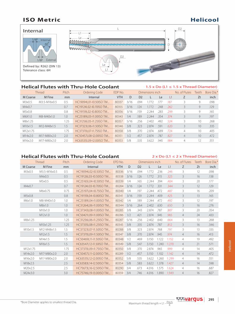
ISO Metric
1/4P60º
1/8P
LL1
D
D2
Le
Le
L1
D2
Helicool
295
Hel
icoo
l
External
Internal
Defined by: R262 (DIN 13)Tolerance class: 6H
Internal
HelicoolISO Metric
Maximum thread length = L1 - Pitch 4
*Bore Diameter applies to smallest thread Dia.
Helical Flutes with Thru-Hole Coolant 2 x Do (L1 ≤ 2 x Thread Diameter)
Thread Pitch Ordering Code EPD No. Dimensions inch No. of Flutes Teeth Bore Dia.*M Coarse M Fine mm Internal VTH D D2 L Le L1 Z Zt inchM3x0.5 M3.5-M16x0.5 0.5 HC19094L02-I0.50ISO TM... 80336 3/16 .094 1.772 .236 .246 3 12 .098
M4x0.5 0.5 HC19126L03-I0.50ISO TM... 80338 3/16 .126 1.772 .315 .325 3 16 .138M5x0.5 0.5 HC25165L04-I0.50ISO TM... 80339 1/4 .165 2.244 .394 .404 3 20 .177
M4x0.7 0.7 HC19124L03-I0.70ISO TM... 80284 3/16 .124 1.772 .331 .344 3 12 .129M6x0.75 0.75 HC25197L04-I0.75ISO TM... 80340 1/4 .197 2.244 .472 .487 3 16 .209
M5x0.8 0.8 HC19159L04-I0.80ISO TM... 80341 3/16 .159 2.244 .409 .425 3 13 .165M6x1.0 M8-M40x1.0 1.0 HC25189L04-I1.00ISO TM... 80342 1/4 .189 2.244 .472 .492 3 12 .197
M8x1.0 1.0 HC31264L06-I1.00ISO TM... 80344 5/16 .264 2.402 .630 .650 3 16 .276M10x1.0 1.0 HC37343L08-I1.00ISO TM... 80285 3/8 .343 2.874 .787 .807 3 20 .354M12x1.0 1.0 HC50421L09-I1.00ISO TM... 80286 1/2 .421 2.874 .945 .965 4 24 .433
M8x1.25 1.25 HC31256L06-I1.25ISO TM... 80287 5/16 .256 2.402 .640 .664 3 13 .268M10x1.25 1.25 HC37335L08-I1.25ISO TM... 80345 3/8 .335 2.874 .787 .812 3 16 .346
M10x1.5 M12-M48x1.5 1.5 HC37323L07-I1.50ISO TM... 80288 3/8 .323 2.874 .768 .797 3 13 .335M12x1.5 1.5 HC37370L09-I1.50ISO TM... 80347 3/8 .370 2.874 .945 .974 4 16 .413M14x1.5 1.5 HC50469L11-I1.50ISO TM... 80348 1/2 .469 3.150 1.122 1.152 4 19 .492M16x1.5 1.5 HC63547L12-I1.50ISO TM... 80349 5/8 .547 3.150 1.240 1.270 4 21 .571
M12x1.75 1.75 HC37370L09-I1.75ISO TM... 80350 3/8 .370 2.874 .965 .999 4 14 .405M14x2.0 M17-M80x2.0 2.0 HC50457L11-I2.00ISO TM... 80289 1/2 .457 3.150 1.102 1.142 4 14 .472M16x2.0 M17-M80x2.0 2.0 HC63535L12-I2.00ISO TM... 80352 5/8 .535 3.622 1.260 1.299 4 16 .551M18x2.5 2.5 HC63583L14-I2.50ISO TM... 80354 5/8 .583 3.622 1.378 1.427 4 14 .598M20x2.5 2.5 HC75673L16-I2.50ISO TM... 80290 3/4 .673 4.016 1.575 1.624 4 16 .687M24x3.0 3.0 HC75746L19-I3.00ISO TM... 80359 3/4 .746 4.016 1.890 1.949 4 16 .827
Helical Flutes with Thru-Hole Coolant 1.5 x Do (L1 ≤ 1.5 x Thread Diameter)
Thread Pitch Ordering Code EDP No. Dimensions inch No. of Flutes Teeth Bore Dia.*M Coarse M Fine mm Internal VTH D D2 L Le L1 Z Zt inchM3x0.5 M3.5-M16x0.5 0.5 HC19094L01-I0.50ISO TM... 80337 3/16 .094 1.772 .177 .187 3 9 .098M4x0.7 0.7 HC19124L02-I0.70ISO TM... 80355 3/16 .124 1.772 .248 .262 3 9 .129M5x0.8 0.8 HC19159L02-I0.80ISO TM... 80356 3/16 .159 2.244 .283 .299 3 9 .165M6X1.0 M8-M40x1.0 1.0 HC25189L03-I1.00ISO TM... 80343 1/4 .189 2.244 .354 .374 3 9 .197M8x1.25 1.25 HC31256L05-I1.25ISO TM... 80357 5/16 .256 2.402 .492 .524 3 10 .268M10x1.5 M12-M48x1.5 1.5 HC37323L06-I1.50ISO TM... 80346 3/8 .323 2.874 .591 .620 3 10 .335M12x1.75 1.75 HC37370L07-I1.75ISO TM... 80358 3/8 .370 2.874 .689 .724 4 10 .405M14x2.0 M17-M80x2.0 2.0 HC50457L08-I2.00ISO TM... 80351 1/2 .457 2.874 .787 .827 4 10 .472M16x2.0 M17-M80x2.0 2.0 HC63535L09-I2.00ISO TM... 80353 5/8 .535 3.622 .945 .984 4 12 .551
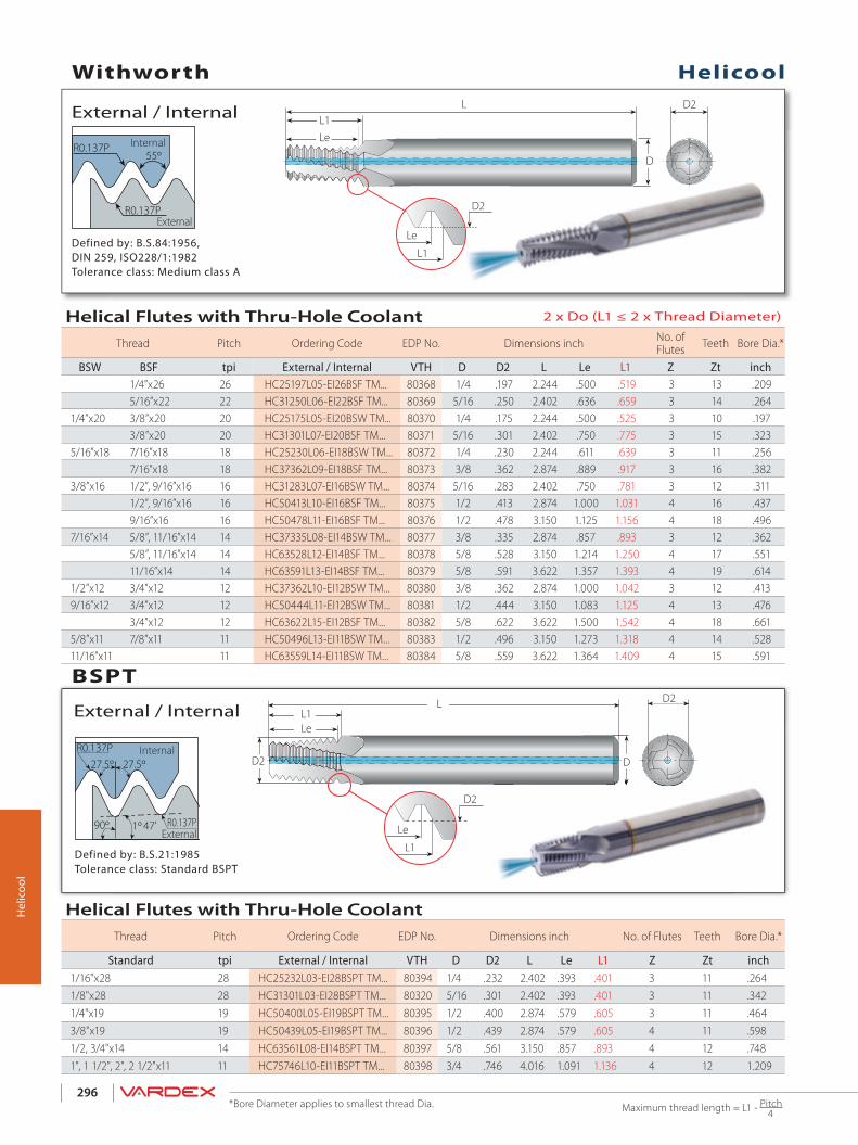
R0.137P
47' R0.137P
D2
D2
Le
L1
D2
D
LL1Le
27.5º 27.5º
90º 1º
55º
R0.137P
R0.137P
LL1
D
D2
Le
Le
L1
D2
296
Hel
icoo
l
Defined by: B.S.21:1985Tolerance class: Standard BSPT
External / Internal
Internal
External
Defined by: B.S.84:1956, DIN 259, ISO228/1:1982Tolerance class: Medium class A
External / Internal
External
Internal
Helicool
BSPT
Withworth
Maximum thread length = L1 - Pitch 4
*Bore Diameter applies to smallest thread Dia.
Helical Flutes with Thru-Hole Coolant 2 x Do (L1 ≤ 2 x Thread Diameter)
Thread Pitch Ordering Code EDP No. Dimensions inch No. ofFlutes Teeth Bore Dia.*
BSW BSF tpi External / Internal VTH D D2 L Le L1 Z Zt inch1/4”x26 26 HC25197L05-EI26BSF TM... 80368 1/4 .197 2.244 .500 .519 3 13 .2095/16”x22 22 HC31250L06-EI22BSF TM... 80369 5/16 .250 2.402 .636 .659 3 14 .264
1/4”x20 3/8”x20 20 HC25175L05-EI20BSW TM... 80370 1/4 .175 2.244 .500 .525 3 10 .1973/8”x20 20 HC31301L07-EI20BSF TM... 80371 5/16 .301 2.402 .750 .775 3 15 .323
5/16”x18 7/16”x18 18 HC25230L06-EI18BSW TM... 80372 1/4 .230 2.244 .611 .639 3 11 .2567/16”x18 18 HC37362L09-EI18BSF TM... 80373 3/8 .362 2.874 .889 .917 3 16 .382
3/8”x16 1/2”, 9/16”x16 16 HC31283L07-EI16BSW TM... 80374 5/16 .283 2.402 .750 .781 3 12 .3111/2”, 9/16”x16 16 HC50413L10-EI16BSF TM... 80375 1/2 .413 2.874 1.000 1.031 4 16 .4379/16”x16 16 HC50478L11-EI16BSF TM... 80376 1/2 .478 3.150 1.125 1.156 4 18 .496
7/16”x14 5/8”, 11/16”x14 14 HC37335L08-EI14BSW TM... 80377 3/8 .335 2.874 .857 .893 3 12 .3625/8”, 11/16”x14 14 HC63528L12-EI14BSF TM... 80378 5/8 .528 3.150 1.214 1.250 4 17 .55111/16”x14 14 HC63591L13-EI14BSF TM... 80379 5/8 .591 3.622 1.357 1.393 4 19 .614
1/2”x12 3/4”x12 12 HC37362L10-EI12BSW TM... 80380 3/8 .362 2.874 1.000 1.042 3 12 .4139/16”x12 3/4”x12 12 HC50444L11-EI12BSW TM... 80381 1/2 .444 3.150 1.083 1.125 4 13 .476
3/4”x12 12 HC63622L15-EI12BSF TM... 80382 5/8 .622 3.622 1.500 1.542 4 18 .6615/8”x11 7/8”x11 11 HC50496L13-EI11BSW TM... 80383 1/2 .496 3.150 1.273 1.318 4 14 .52811/16”x11 11 HC63559L14-EI11BSW TM... 80384 5/8 .559 3.622 1.364 1.409 4 15 .591
Helical Flutes with Thru-Hole Coolant Thread Pitch Ordering Code EDP No. Dimensions inch No. of Flutes Teeth Bore Dia.*
Standard tpi External / Internal VTH D D2 L Le L1 Z Zt inch1/16"x28 28 HC25232L03-EI28BSPT TM... 80394 1/4 .232 2.402 .393 .401 3 11 .2641/8"x28 28 HC31301L03-EI28BSPT TM... 80320 5/16 .301 2.402 .393 .401 3 11 .3421/4"x19 19 HC50400L05-EI19BSPT TM... 80395 1/2 .400 2.874 .579 .605 3 11 .4643/8"x19 19 HC50439L05-EI19BSPT TM... 80396 1/2 .439 2.874 .579 .605 4 11 .5981/2, 3/4"x14 14 HC63561L08-EI14BSPT TM... 80397 5/8 .561 3.150 .857 .893 4 12 .7481", 1 1/2", 2", 2 1/2"x11 11 HC75746L10-EI11BSPT TM... 80398 3/4 .746 4.016 1.091 1.136 4 12 1.209

LL1
D
D2
Le
Le
L1
D2R 0.137P
R 0.137P55º
297
Hel
icoo
l
Defined by: B.S.2779:1956 Tolerance class: Medium class
External / Internal
External
Internal
HelicoolBSP (G)
Maximum thread length = L1 - Pitch 4
*Bore Diameter applies to smallest thread Dia.
Helical Flutes with Thru-Hole Coolant 2 x Do (L1 ≤ 2 x Thread Diameter)
Thread Pitch Ordering Code EDP No. Dimensions inch No. of Flutes Teeth Bore Dia.*
Standard tpi External / Internal VTH D D2 L Le L1 Z Zt inch1/16", 1/8"x28 28 HC31252L06-EI28BSP TM... 80385 5/16 .252 2.402 .607 .625 3 17 .2641/8"x28 28 HC37323L07-EI28BSP TM... 80387 3/8 .323 2.874 .750 .768 3 21 .3241/4", 3/8"x19 19 HC50433L10-EI19BSP TM... 80319 1/2 .433 3.150 1.053 1.079 4 20 .4653/8"x19 19 HC63571L13-EI19BSP TM... 80390 5/8 .571 3.622 1.316 1.342 4 25 .6021/2"-7/8"x14 14 HC75705L16-EI14BSP TM... 80392 3/4 .705 4.016 1.643 1.678 4 23 .752
Helical Flutes with Thru-Hole Coolant 1.5 x Do (L1 ≤ 1.5 x Thread Diameter)
Thread Pitch Ordering Code EDP No. Dimensions inch No. of Flutes Teeth Bore Dia.*
Standard tpi External / Internal VTH D D2 L Le L1 Z Zt inch1/16", 1/8"x28 28 HC31252L04-EI28BSP TM... 80386 5/16 .252 2.402 .464 .480 3 13 .2641/8"x28 28 HC37323L05-EI28BSP TM... 80388 3/8 .323 2.874 .571 .591 3 16 .3241/4", 3/8"x19 19 HC50433L08-EI19BSP TM... 80389 1/2 .433 2.874 .789 .815 4 15 .4653/8"x19 19 HC63571L10-EI19BSP TM... 80391 5/8 .571 3.622 1.000 1.028 4 19 .6021"-4"x11 11 HC75746L16-EI11BSP TM... 80393 3/4 .746 4.016 1.636 1.681 4 18 1.208
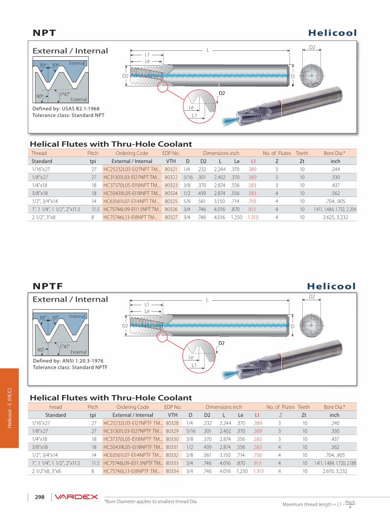
1º47’
D2
D2
Le
L1
D2
D
LL1Le
30º 30º
90º
1°47’
D2
D2
Le
L1
D2
D
LL1Le
30° 30°
90°D2
D2
298
Hel
icoo
l - C
(HCC
)
Defined by: ANSI 1.20.3-1976Tolerance class: Standard NPTF
External / Internal
Internal
External
Defined by: USAS B2.1:1968Tolerance class: Standard NPT
External / InternalInternal
External
NPT
Helicool
Helicool
NPTF
Maximum thread length = L1 - Pitch 4
*Bore Diameter applies to smallest thread Dia.
Helical Flutes with Thru-Hole Coolant hread Pitch Ordering Code EDP No. Dimensions inch No. of Flutes Teeth Bore Dia.*
Standard tpi External / Internal VTH D D2 L Le L1 Z Zt inch1/16”x27 27 HC25232L03-EI27NPTF TM... 80328 1/4 .232 2.244 .370 .389 3 10 .2401/8”x27 27 HC31301L03-EI27NPTF TM... 80329 5/16 .301 2.402 .370 .389 3 10 .3301/4”x18 18 HC37370L05-EI18NPTF TM... 80330 3/8 .370 2.874 .556 .583 3 10 .4373/8”x18 18 HC50439L05-EI18NPTF TM... 80331 1/2 .439 2.874 .556 .583 4 10 .5621/2”, 3/4”x14 14 HC63561L07-EI14NPTF TM... 80332 5/8 .561 3.150 .714 .750 4 10 .704, .9051”, 1 1/4”, 1 1/2”, 2”x11.5 11.5 HC75746L09-EI11.5NPTF TM... 80333 3/4 .746 4.016 .870 .913 4 10 1.411, 1.484, 1.720, 2.1882 1/2”x8; 3”x8 8 HC75746L13-EI8NPTF TM... 80334 3/4 .746 4.016 1.250 1.313 4 10 2.610, 3.232
Helical Flutes with Thru-Hole Coolant Thread Pitch Ordering Code EDP No. Dimensions inch No. of Flutes Teeth Bore Dia.*Standard tpi External / Internal VTH D D2 L Le L1 Z Zt inch1/16”x27 27 HC25232L03-EI27NPT TM... 80321 1/4 .232 2.244 .370 .389 3 10 .2441/8”x27 27 HC31301L03-EI27NPT TM... 80322 5/16 .301 2.402 .370 .389 3 10 .3301/4”x18 18 HC37370L05-EI18NPT TM... 80323 3/8 .370 2.874 .556 .583 3 10 .4373/8”x18 18 HC50439L05-EI18NPT TM... 80324 1/2 .439 2.874 .556 .583 4 10 .5621/2”, 3/4”x14 14 HC63561L07-EI14NPT TM... 80325 5/8 .561 3.150 .714 .750 4 10 .704, .9051”, 1 1/4”, 1 1/2”, 2”x11.5 11.5 HC75746L09-EI11.5NPT TM... 80326 3/4 .746 4.016 .870 .913 4 10 1.411, 1.484, 1.732, 2.2042 1/2”, 3”x8 8 HC75746L13-EI8NPT TM... 80327 3/4 .746 4.016 1.250 1.313 4 10 2.625, 3.232

1/4P
1/8P
D2L1Le
L
D2
L1Le
D60° DDD
299
Hel
icoo
l-R (H
CR)
Defined by: ANSI B1.1.74Tolerance class: 2B
Internal
External / Internal
Internal
External
Helicool-R (HCR)American UN
Maximum thread length = L1 - Pitch 4
*Bore Diameter applies to smallest thread Dia.
HeliCool-R (HCR)Helical Flutes with Radial Cooling 2 x Do (L1 ≤ 2 x Thread Diameter)
Thread Pitch Ordering Code EDP No. Dimensions inch No. of Flutes Teeth Bore Dia.*
UNC UNF UNEF tpi Internal VTH D D2 L Le L1 Z Zt inchNo.10-32 No.12-3/8”x32 32 HCR19150L03-I32UNF TM... 80458 3/16 .150 1.772 .375 .391 3 12 .1571/4"x28 7/16”, 1/2"x28 28 HCR25203L05-I28UNF TM... 80459 1/4 .203 2.244 .500 .518 3 14 .216
No.10-24 5/16”, 3/8"x24 9/16”-11/16”x24 24 HCR19141L04-I24UNC TM... 80460 3/16 .141 1.772 .375 .396 3 9 .150No.12-24 5/16”, 3/8"x24 9/16”-11/16”x24 24 HCR19163L04-I24UNC TM... 80461 3/16 .163 1.772 .417 .437 3 10 .177
5/16”, 3/8"x24 9/16”-11/16”x24 24 HCR31263L06-I24UNF TM... 80462 5/16 .263 2.402 .625 .646 3 15 .2723/8"x24 9/16”-11/16”x24 24 HCR37323L07-I24UNF TM... 80463 3/8 .323 2.874 .750 .771 3 18 .335
1/4"x20 7/16”, 1/2"x20 3/4”-1"x20 20 HCR25192L05-I20UNC TM... 80464 1/4 .192 2.244 .500 .525 3 10 .2011/2"x20 3/4”-1”x20 20 HCR50437L10-I20UNF TM... 80465 1/2 .437 3.150 1.000 1.025 4 20 .453
5/16"x18 9/16”, 5/8”x18 11/16"-1 11/16”x18 18 HCR31242L16-I18UNC TM... 80466 5/16 .242 2.402 .611 .639 3 11 .2603/8"x16 3/4”x16 16 HCR31301L07-I16UNC TM... 80467 5/16 .301 2.402 .750 .781 3 12 .3157/16"x14 7/8”x14 14 HCR37354L08-I14UNC TM... 80468 3/8 .354 2.874 .857 .893 3 12 .3701/2"x13 13 HCR50407L10-I13UNC TM... 80469 1/2 .407 3.150 1.000 1.039 4 13 .4309/16"x12 1”-1 1/2”x12 12 HCR50465L11-I12UNC TM... 80470 1/2 .465 3.150 1.084 1.125 4 13 .484
HeliCool-R (HCR)Helical Flutes with Radial Cooling
Thread Pitch Ordering Code EDP No. Dimensions inch No. of Flutes Teeth Bore Dia.*
Standard tpi External / Internal VTH D D2 L Le L1 Z Zt inch1/16”x27 27 HCR25232L03-EI27NPT TM... 80573 1/4 .232 2.244 .370 .389 3 10 .2441/8”x27 27 HCR31301L03-EI27NPT TM... 80574 5/16 .301 2.402 .370 .389 3 10 .3301/4”x18 18 HCR37370L05-EI18NPT TM... 80575 3/8 .370 2.874 .556 .583 3 10 .4373/8”x18 18 HCR50439L05-EI18NPT TM... 80576 1/2 .439 2.874 .556 .583 4 10 .5621/2”, 3/4”x14 14 HCR63561L07-EI14NPT TM... 80577 5/8 .561 3.150 .714 .750 4 10 .704, .9051”, 1 1/4”, 1 1/2” , 2”x11.5 11.5 HCR75746L09-EI11.5NPT TM... 80578 3/4 .746 4.016 .870 .913 4 10 1.411, 1.484, 1.732, 2.2042 1/2”, 3”x8 8 HCR75746L13-EI8NPT TM... 80579 3/4 .746 4.016 1.250 1.313 4 10 2.625, 3.232
Helicool-R for Improved Chip Evacuation for Thru-Holes
Defined by: USAS B2.1:1968Tolerance class: Standard NPT
NPT
Helicool-R for Improved Chip Evacuation for Thru-Holes
D2L1
Le
L
D2
L1
Le
D60O
Helicool-R for Improved Chip Evacuation for Thru-Holes
Internal
External

1 32 3
1/4P
1/8P
60°
D2L1
Le
L
LcL1
D2Dc
45º
DDDD
300
Defined by: ANSI B1.1.74Tolerance class: 2B
Internal
Internal
External
Helicool-C (HCC)American UN
Dc = Minimum recommended chamfer diameter
Helicool-C Operating Cycle
Thread MillingChamferingPositioning
Maximum thread length = L1 - Pitch 4
*Bore Diameter applies to smallest thread Dia.
Hel
icoo
l - C
(HCC
)
HeliCool-R (HCR)Helical Flutes with Axial Coolant - Thru & Chamfer 2 x Do (L1 ≤ 2 x Thread Diameter)
Thread Pitch Ordering Code EDP No. Dimensions inch No. of Flutes Teeth Bore
Dia.*
UNC UNF UNEF tpi Internal VTH D D2 Dc L Le L1 Le Z Zt inchNo.10-32 No.12-3/8”x32 32 HCC25150L03-I32UNF TM... 80449 1/4 .150 .202 2.244 .375 .391 .417 3 12 .1571/4"x28 7/16”, 1/2"x28 28 HCC31203L05-I28UNF TM... 80450 5/16 .203 .262 2.402 .500 .518 .549 3 14 .216
No.10-24 5/16”, 3/8”x24 9/16”-11/16”x24 24 HCC25141L04-I24UNC TM... 80451 1/4 .141 .202 2.244 .375 .396 .425 3 9 .150No.12-24 5/16”, 3/8”x24 9/16”-11/16”x24 24 HCC25163L04-I24UNC TM... 80452 1/4 .163 .228 2.244 .417 .437 .468 3 10 .177
5/16”, 3/8”x24 9/16”-11/16”x24 24 HCC37263L06-I24UNF TM... 80453 3/8 .263 .324 2.874 .625 .646 .678 3 15 .2723/8"x24 9/16”-11/16”x24 24 HCC50323L07-I24UNF TM... 80454 1/2 .323 .387 3.150 .750 .771 .804 3 18 .335
1/4"x20 7/16", 1/2”x20 3/4”-1"x20 20 HCC31192L05-I20UNC TM... 80455 5/16 .192 .262 2.402 .500 .525 .558 3 10 .2011/2”x20 3/4”-1”x20 20 HCC63437L10-I20UNF TM... 80456 5/8 .437 .512 3.622 1.000 1.025 1.065 3 20 .453
5/16"x18 9/16", 5/8”x18 11/16"-1 11/16”x18 18 HCC37242L16-I18UNC TM... 80457 3/8 .242 .324 2.874 .611 .639 .676 3 11 .2603/8"x16 3/4”x16 16 HCC50301L07-I16UNC TM... 80528 1/2 .301 .387 3.150 .750 .781 .814 3 12 .3157/16"x14 7/8”x14 14 HCC50354L08-I14UNC TM... 80529 1/2 .354 .449 3.150 .857 .893 .937 3 12 .3701/2"x13 13 HCC63407L10-I13UNC TM... 80530 5/8 .407 .512 3.622 1.000 1.039 1.087 4 13 .4309/16"x12 1”-1 1/2”x12 12 HCC63465L11-I12UNC TM... 80531 5/8 .465 .574 3.622 1.084 1.125 1.178 4 13 .484
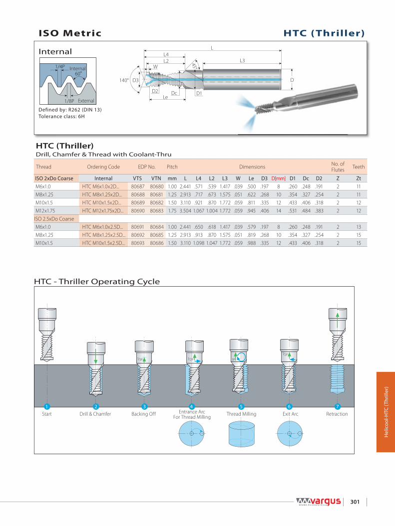
1/4P
1/8P
60°W
L2L4
D3140°
D2 Dc D1
L3
L
D
45°
Le
1 2 3 4 5 6 7
1/3 P 1/2 P 1 P
1/2 P
301
Hel
icoo
l-HTC
(Thr
iller
)
Defined by: R262 (DIN 13)Tolerance class: 6H
Internal
Internal
External
HTC (Thriller)ISO Metric
RetractionExit ArcThread MillingEntrance ArcFor Thread MillingBacking OffDrill & ChamferStart
HTC - Thriller Operating Cycle
HTC (Thriller)Drill, Chamfer & Thread with Coolant-Thru
Thread Ordering Code EDP No. Pitch Dimensions No. of Flutes Teeth
ISO 2xDo Coarse Internal VTS VTN mm L L4 L2 L3 W Le D3 D[mm] D1 Dc D2 Z Zt M6x1.0 HTC M6x1.0x2D... 80687 80680 1.00 2.441 .571 .539 1.417 .039 .500 .197 8 .260 .248 .191 2 11 M8x1.25 HTC M8x1.25x2D... 80688 80681 1.25 2.913 .717 .673 1.575 .051 .622 .268 10 .354 .327 .254 2 11 M10x1.5 HTC M10x1.5x2D... 80689 80682 1.50 3.110 .921 .870 1.772 .059 .811 .335 12 .433 .406 .318 2 12 M12x1.75 HTC M12x1.75x2D... 80690 80683 1.75 3.504 1.067 1.004 1.772 .059 .945 .406 14 .531 .484 .383 2 12ISO 2.5xDo Coarse M6x1.0 HTC M6x1.0x2.5D... 80691 80684 1.00 2.441 .650 .618 1.417 .039 .579 .197 8 .260 .248 .191 2 13 M8x1.25 HTC M8x1.25x2.5D... 80692 80685 1.25 2.913 .913 .870 1.575 .051 .819 .268 10 .354 .327 .254 2 15 M10x1.5 HTC M10x1.5x2.5D... 80693 80686 1.50 3.110 1.098 1.047 1.772 .059 .988 .335 12 .433 .406 .318 2 15

1/4P
1/8P
60°
Le
L
D
D2
302
He-
Lex
Defined by: ANSI B1.1.74Tolerance class: 2A/2B
External / Internal
Internal
External
He-LexAmerican UN
*Bore Diameter applies to smallest thread Dia.
He-Lex Flutes - Internal 2 x Do (L1 ≤ 2 x Thread Diameter)
Thread Pitch Ordering Code EDP No. Dimensions inch No. of Flutes Teeth Bore Dia.*UNC UNF tpi Internal VTH D D2 L Le Z Zt inch
No.10-32 32 HX1/8".121”-I32UNF TM... 80534 1/8 .121 2.0 .312 3 10 .157No.10-28 28 HX1/8".121”-I28UNF TM... 80535 1/8 .121 2.0 .321 3 9 .155
No.12-28 28 HX3/16".150”-I28UNF TM... 80536 3/16 .150 2.5 .464 3 13 .1811/4"x28 28 HX3/16".181”-I28UNF TM... 80537 3/16 .181 2.5 .500 3 14 .217
No.10-24 24 HX1/8".120”-I24UNC TM... 80538 1/8 .120 2.0 .333 3 8 .150No.12-24 24 HX3/16".138”-I24UNC TM... 80539 3/16 .138 2.5 .458 3 11 .177 5/16"x24 24 HX1/4".232”-I24UNF TM... 80540 1/4 .232 2.5 .625 3 15 .268 3/8"x24 24 HX5/16".291”-I24UNF TM... 80541 5/16 .291 3.0 .750 4 18 .3351/4"x20 20 HX3/16".181”-I20UNC TM... 80542 3/16 .181 2.5 .500 3 10 .205 1/2"x20 20 HX3/8".371”-I20UNF TM... 80543 3/8 .371 3.5 1.000 4 20 .453 7/16"x20 20 HX3/8".335”-I20UNF TM... 80544 3/8 .335 3.5 .900 4 18 .3865/16"x18 18 HX1/4".232”-I18UNC TM... 80545 1/4 .232 2.5 .667 3 12 .256 9/16"x18 18 HX3/8".371”-I18UNF TM... 80546 3/8 .371 3.5 .889 4 16 .504 5/8"x18 18 HX1/2".496”-I18UNF TM... 80547 1/2 .496 3.5 1.278 4 23 .5713/8"x16 16 HX5/16".285”-I16UNC TM... 80548 5/16 .285 3.0 .750 4 12 .315 3/4"x16 16 HX1/2".496”-I16UNF TM... 80549 1/2 .496 3.5 1.250 4 20 .6897/16"x14 14 HX5/16".305”-I14UNC TM... 80550 5/16 .305 3.0 .786 4 11 .3661/2"x13 13 HX3/8".350”-I13UNC TM... 80551 3/8 .350 3.5 .923 4 12 .4259/16"x12 12 HX3/8".371”-I12UNC TM... 80552 3/8 .371 3.5 .917 4 11 .4845/8"x11 11 HX1/2".469”-I11UNC TM... 80553 1/2 .469 3.5 1.273 4 14 .5313/4"x10 10 HX1/2".496”-I10UNC TM... 80554 1/2 .496 3.5 1.300 4 13 .6507/8"x9 9 HX5/8".621”-I9UNC TM... 80555 5/8 .621 4.0 1.444 4 13 .7681"x8 8 HX5/8".621”-I8UNC TM... 80556 5/8 .621 4.0 1.375 4 11 .878

Le
L
D
D2
1/8P
1/4P60° Le
303
He-
Lex
Defined by: R262 (DIN 13)Tolerance class: 6g/6H
External / Internal
Internal
External
He-LexISO Metric
*Bore Diameter applies to smallest thread Dia.
He-Lex Flutes - Internal 2 x Do (L1 ≤ 2 x Thread Diameter)
Thread Pitch Ordering Code EDP No. Dimensions inch No. of Flutes Teeth Bore Dia.*M Coarse M Fine mm Internal VTH D[mm] D2 L Le Z Zt inchM3x0.5 M3.5-M16x0.5 0.5 H04022L06-I0.5ISO TM... 80897 4 .087 1.772 .236 3 12 .098
M4x0.5 0.5 H04030L08-I0.5ISO TM... 80898 4 .118 1.772 .315 3 16 .138M5x0.5 0.5 H04039L10-I0.5ISO TM... 80899 4 .154 1.772 .394 3 20 .177
M4x0.7 0.7 H04028L08-I0.7ISO TM... 80900 4 .110 1.772 .331 3 12 .130M6x0.75 0.75 H04039L12-I0.75ISO TM... 80901 4 .154 1.772 .472 3 16 .209
M5x0.8 0.8 H04035L10-I0.8ISO TM... 80902 4 .138 1.772 .409 3 13 .165M6x1.0 M8-M40x1.0 1.0 H04039L12-I1.0ISO TM... 80903 4 .154 1.772 .472 3 12 .197
M8x1.0 1.0 H06059L16-I1.0ISO TM... 80904 6 .232 2.244 .630 3 16 .276M10x1.0 1.0 H08079L20-I1.0ISO TM... 80905 8 .311 2.480 .787 3 20 .354M12x1.0 1.0 H10099L24-I1.0ISO TM... 80801 10 .390 2.874 .945 4 24 .433
M8x1.25 1.25 H06058L16-I1.25ISO TM... 80907 6 .228 2.244 .640 3 13 .268M10x1.25 1.25 H08077L20-I1.25ISO TM... 80908 8 .303 2.480 .787 3 16 .346
M10x1.5 M12-M48x1.5 1.5 H08077L21-I1.5ISO TM... 80909 8 .303 2.480 .827 3 14 .335M12x1.5 1.5 H10094L24-I1.5ISO TM... 80910 10 .370 2.874 .945 4 16 .413M14x1.5 1.5 H12112L28-I1.5ISO TM... 80911 12 .441 3.268 1.122 4 19 .492M16x1.5 1.5 H12119L33-I1.5ISO TM... 80912 12 .469 3.268 1.299 4 22 .571
M12x1.75 1.75 H10087L24-I1.75ISO TM... 80913 10 .343 2.874 .965 4 14 .402M14x2.0 M17-M80x2.0 2.0 H10099L28-I2.0ISO TM... 80914 10 .390 2.874 1.102 4 14 .472M16x2.0 M17-M80x2.0 2.0 H12119L32-I2.0ISO TM... 80915 12 .469 3.268 1.260 4 16 .551M18-M22x2.5 2.5 H16139L40-I2.5ISO TM... 80916 16 .547 3.622 1.575 5 16 .610M24x3.0 3.0 H16159L42-I3.0ISO TM... 80917 16 .626 3.622 1.654 4 14 .827
He-Lex Flutes - External 2 x Do (L1 ≤ 2 x Thread Diameter)
Thread Pitch Ordering Code EDP No. Dimensions inch No. of Flutes TeethM Coarse mm External VTH D[mm] D2 L Le Z Zt
M3x0.5 0.5 H04039L06-E0.5ISO TM... 80891 4 .154 1.772 .236 3 12M4.5x0.75 0.75 H04039L09-E0.75ISO TM... 80892 4 .154 1.772 .354 3 12M6x1.0 1.0 H04039L12-E1.0ISO TM... 80893 4 .154 1.772 .472 3 12
M8x1.25 1.25 H06059L16-E1.25ISO TM... 80894 6 .232 2.244 .640 3 13
M10x1.5 1.5 H08079L21-E1.5ISO TM... 80895 8 .311 2.480 .827 3 14M14x2.0 2.0 H10099L28-E2.0ISO TM... 80896 10 .390 2.874 1.102 4 14
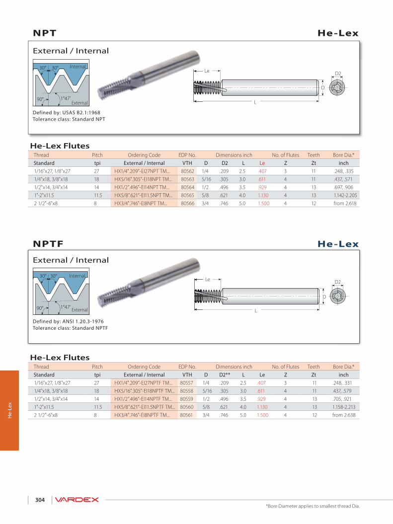
30°30°
90° 1°47’
Le
L
D
D2
Le
L
D
D230°30°
90° 1°47’
304
He-
Lex
Defined by: ANSI 1.20.3-1976Tolerance class: Standard NPTF
External / Internal
Internal
External
Defined by: USAS B2.1:1968Tolerance class: Standard NPT
External / Internal
Internal
External
He-Lex
He-Lex
NPTF
NPT
*Bore Diameter applies to smallest thread Dia.
He-Lex FlutesThread Pitch Ordering Code EDP No. Dimensions inch No. of Flutes Teeth Bore Dia.*Standard tpi External / Internal VTH D D2 L Le Z Zt inch1/16"x27, 1/8"x27 27 HX1/4".209”-EI27NPT TM... 80562 1/4 .209 2.5 .407 3 11 .248, .3351/4"x18, 3/8"x18 18 HX5/16".305”-EI18NPT TM... 80563 5/16 .305 3.0 .611 4 11 .437, .5711/2"x14, 3/4"x14 14 HX1/2".496”-EI14NPT TM... 80564 1/2 .496 3.5 .929 4 13 .697, .9061"-2"x11.5 11.5 HX5/8".621”-EI11.5NPT TM... 80565 5/8 .621 4.0 1.130 4 13 1.142-2.2052 1/2"-6"x8 8 HX3/4".746”-EI8NPT TM... 80566 3/4 .746 5.0 1.500 4 12 from 2.618
He-Lex FlutesThread Pitch Ordering Code EDP No. Dimensions inch No. of Flutes Teeth Bore Dia.*Standard tpi External / Internal VTH D D2** L Le Z Zt inch1/16"x27, 1/8"x27 27 HX1/4".209”-EI27NPTF TM... 80557 1/4 .209 2.5 .407 3 11 .248, .3311/4"x18, 3/8"x18 18 HX5/16".305”-EI18NPTF TM... 80558 5/16 .305 3.0 .611 4 11 .437, .5791/2"x14, 3/4"x14 14 HX1/2".496”-EI14NPTF TM... 80559 1/2 .496 3.5 .929 4 13 .705, .9211"-2"x11.5 11.5 HX5/8".621”-EI11.5NPTF TM... 80560 5/8 .621 4.0 1.130 4 13 1.158-2.2132 1/2"-6"x8 8 HX3/4".746”-EI8NPTF TM... 80561 3/4 .746 5.0 1.500 4 12 from 2.638

ISO Metric
Internal
Defined by: R262 (DIN 13)Tolerance class: 6H
1/4P
60°
1/8P
Internal
External
L1D2L
D
Deep Threading
Internal
1/4P
60o
1/8P
Internal
External
L1D2L
D
60°
ISO Metric
1/4P60º
1/8P
LL1
D
D2
Le
Le
L1
D2
Helicool
305
Dee
p Th
read
ing
Internal
External
Internal
External
Deep Threading - Long Tools for Deep HolesMin. Thread Pitch Ordering Code EDP No. Dimensions inch
M coarse M fine UN, UNS, UNF, UNEF mm tpi Internal VTH D D2 L L1 Z Zt
M5x0.8 M5x0.5, M5X0.75
No.10-56UNS, No.10-48UNS, No.10-40UNS,No.10-36UNS, No.10-32UNF 0.5-0.8 32-56 D1T19154L063-ITA60 TM... 80414 3/16 0.154 1.750 0.63 4 1
M6x1.0 M6x0.5, M6X0.75
No.12-56UNS, No.12-48UNS, 1⁄4-40UNS,1⁄4-36UNS, 1⁄4-32UNEF, 1⁄4-28UNF,1⁄4-27UNS, 1⁄4-24UNS
0.5-1.0 24-56 D1T25191L079-ITB60 TM... 80415 1/4 0.191 2.000 0.79 5 1
M8x1.25M7x0.5, M7x0.75, M7.5x1.0
5⁄16-48UNS, 5⁄16-40UNS, 5⁄16-36UNS,5⁄16-32UNEF, 5⁄16-28UN, 5⁄16-27UNS,5⁄16-24UNS, 5⁄16-20UN
0.5-1.25 20-48 D1T25232L100-ITF60 TM... 80416 1/4 0.232 2.500 1.00 5 1
-M10.5x0.5, M11x0.75, M11x1.0
7⁄16-32UN, 7⁄16-28UNEF, 7⁄16-27UNS,7⁄16-24UNS 0.5-1.0 24-56 D1T37370L138-ITB60 TM... 80417 3/8 0.39 3.000 1.38 6 1
M10x1.5 M10x1.0, M10X1.25
3⁄8-24UNF, 3⁄8-20UN, 7⁄16-18UNS,7⁄16-16UN 1.0-1.50 16-24 D1T31307L126-ITC60 TM... 80423 5/16 0.311 2.500 1.26 6 1
M12x1.75M12x1.0, M12X1.25, M12x1.5
1⁄2-24UNS, 1⁄2-20UNS, 1⁄2-18UNS,1⁄2-16UNS, 1⁄2-14UNS 1.0-1.75 14-24 D1T37370L150-ITD60 TM... 80424 3/8 0.39 3.000 1.50 6 1
-M13.5x1.0, M14x1.25, M14x1.5
9⁄16-24UNEF 1.0-1.75 14-24 D1T50469L177-ITD60 TM... 80425 1/2 0.469 3.250 1.77 6 1
Defined by: ANSI B1.1.74Tolerance class: 2B
Internal
American UN
Internal
Deep Threading
Deep ThreadingPartial Profile 60°
Deep Threading - Long Tools for Deep Holes 3 x Do (L1 ≤ 3 x Thread Diameter)Thread Pitch Ordering Code EDP No. Dimensions inch No. of Flutes Teeth Bore Dia.UNC UNF tpi Internal VTH D D2 L L1 Z Zt inch
1/4"x20 20 D1T5/16”.157”-I20UNC TM... 80220 5/16 .157 2.480 .787 3 1 .2051/4"x28 28 D1T5/16”.181”-I28UNF TM... 80271 5/16 .181 2.480 .787 3 1 .217
5/16"x18 18 D1T3/8”.205”-I18UNC TM... 80221 3/8 .205 2.874 .984 3 1 .2565/16"x24 24 D1T3/8”.224”-I24UNF TM... 80272 3/8 .224 2.874 .984 3 1 .268
3/8"x16 16 D1T3/8”.264”-I16UNC TM... 80222 3/8 .264 2.874 1.181 3 1 .3153/8"x24 24 D1T3/8”.291”-I24UNF TM... 80273 3/8 .291 2.874 1.181 3 1 .335
7/16"x14 14 D1T1/2”.299”-I14UNC TM... 80274 1/2 .299 3.268 1.378 4 1 .3667/16"x20 20 D1T1/2”.335”-I20UNF TM... 80275 1/2 .335 3.268 1.378 4 1 .386
1/2"x13 13 D1T1/2”.350”-I13UNC TM... 80223 1/2 .350 3.268 1.575 4 1 .4251/2"x20 20 D1T1/2”.398”-I20UNF TM... 80276 1/2 .398 3.268 1.575 4 1 .453
9/16"x12 12 D1T5/8”.406”-I12UNC TM... 80224 5/8 .406 3.780 1.772 4 1 .4849/16"x18 18 D1T5/8”.445”-I18UNF TM... 80277 5/8 .445 3.780 1.772 4 1 .504
5/8"x11 11 D1T5/8”.433”-I11UNC TM... 80225 5/8 .433 3.976 1.969 4 1 .5315/8"x18 18 D1T5/8”.504”-I18UNF TM... 80278 5/8 .504 3.976 1.969 4 1 .571
3/4"x10 10 D1T5/8”.531”-I10UNC TM... 80226 5/8 .531 4.370 2.362 5 1 .6503/4"x16 16 D1T5/8”.610”-I16UNF TM... 80227 5/8 .610 4.370 2.362 5 1 .689

1/4P
1/8P
60°L
L1D2
D
3 FlutesLe = Pitch x 3
L1
306
Mill
Pro
Mill
iPro
Recommended Overhang
Internal
External
Defined by: ANSI B1.1.74Tolerance class: 2B
Internal
American UN MilliPro
*Bore Diameter applies to smallest thread Dia.
MilliProMiniature Thread Mills 3 x Do (L1 ≤ 3 x Thread Diameter)
Thread Pitch Ordering Code EDP No. Dimensions inch No. of Flutes Teeth Bore Dia.*UNC UNF tpi Internal VTH D D2 L L1 Z Zt inch
No.1-72 72 D3T25057L226-I72UN TM... 80443 1/4 .057 2.244 .226 3 3 .059No.4,No.5-40 No.6-40 40 D3T25083L354-I40UN TM... 80263 1/4 .083 2.244 .354 3 3 .091No.5-40 No.6-40 40 D3T25096L394-I40UN TM... 80249 1/4 .096 2.244 .394 3 3 .102No.6,No.8-32 No.10-32 32 D3T25100L433-I32UN TM... 80264 1/4 .100 2.244 .433 3 3 .110No.8-32 No.10-32 32 D3T25126L512-I32UN TM... 80250 1/4 .126 2.244 .512 3 3 .134
1/4”x28 28 D3T25207L772-I28UN TM... 80251 1/4 .207 2.244 .772 3 3 .2165/16”x24 24 D3T31263L965-I24UN TM... 80252 5/16 .263 2.480 .965 3 3 .272
1/4”x20 7/16”x20 20 D3T25192L780-I20UN TM... 80253 1/4 .192 2.244 .780 3 3 .201
MilliProMiniature Thread Mills 2 x Do (L1 ≤ 2 x Thread Diameter)
Thread Pitch Ordering Code EDP No. Dimensions inch No. of Flutes Teeth Bore Dia.*UNC UNF tpi Internal VTH D D2 L L1 Z Zt inch
No.1-72 72 D3T25057L154-I72UN TM... 80215 1/4 .057 2.244 .154 3 3 .059No.1-64 No.2-64 64 D3T25055L165-I64UN TM... 80214 1/4 .055 2.244 .165 3 3 .059No.2-56 No.3-56 56 D3T25065L197-I56UN TM... 80216 1/4 .065 2.244 .197 3 3 .071No.3-48 No.4-48 48 D3T25075L236-I48UN TM... 80217 1/4 .075 2.244 .236 3 3 .079No.4, No.5-40 No.6-40 40 D3T25083L236-I40UN TM... 80218 1/4 .083 2.244 .236 3 3 .090No.5-40 No.6-40 40 D3T25096L283-I40UN TM... 80219 1/4 .096 2.244 .283 3 3 .102
No.8-36 36 D3T25130L343-I36UN TM... 80240 1/4 .130 2.244 .343 3 3 .138No.6, No.8-32 No.10-32 32 D3T25100L292-I32UN TM... 80241 1/4 .100 2.244 .292 3 3 .110No.8-32 No.10-32 32 D3T25126L394-I32UN TM... 80242 1/4 .126 2.244 .394 3 3 .134
1/4”x28 28 D3T25207L520-I28UN TM... 80243 1/4 .207 2.244 .520 3 3 .216No.10-24 5/16”x24 24 D3T25141L402-I24UN TM... 80244 1/4 .141 2.244 .402 3 3 .150
5/16”x24 24 D3T31263L650-I24UN TM... 80245 5/16 .263 2.480 .650 3 3 .2721/4”x20 7/16”x20 20 D3T25192L528-I20UN TM... 80246 1/4 .192 2.244 .528 3 3 .201
7/16”x20 20 D3T37375L906-I20UN TM... 80247 3/8 .375 2.874 .906 3 3 .3903/8”x16 16 D3T31264L752-I16UN TM... 80279 5/16 .264 2.480 .752 3 3 .3157/16”x14 14 D3T37354L917-I14UN TM... 80248 3/8 .354 2.874 .917 3 3 .370
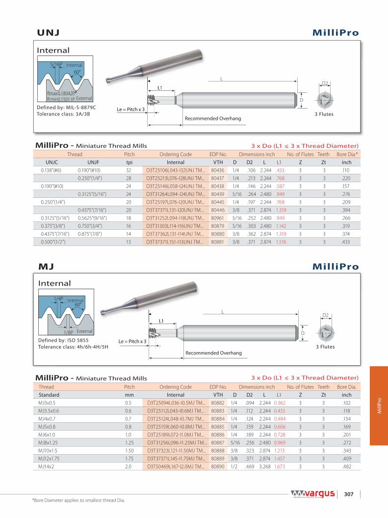
L
L1D2
DR 0.18042PR 0.15011P
5/16P60°
maxmin
3 FlutesLe = Pitch x 3
L1
L
L1D2
D
3 FlutesLe = Pitch x 3
1/4P
1/8P
60°
L1
307
Mill
Pro
Internal
External
Defined by: ISO 5855Tolerance class: 4h/6h-4H/5H
Internal
Recommended Overhang
Internal
External
Defined by: MIL-S-8879CTolerance class: 3A/3B
Internal
Recommended Overhang
MJ
UNJ
MilliPro
MilliPro
MilliPro - Miniature Thread Mills 3 x Do (L1 ≤ 3 x Thread Diameter)
Thread Pitch Ordering Code EDP No. Dimensions inch No. of Flutes Teeth Bore Dia.Standard mm Internal VTH D D2 L L1 Z Zt inchMJ3x0.5 0.5 D3T25094L036-I0.5MJ TM... 80882 1/4 .094 2.244 0.362 3 3 .102MJ3.5x0.6 0.6 D3T25112L043-I0.6MJ TM... 80883 1/4 .112 2.244 0.433 3 3 .118MJ4x0.7 0.7 D3T25124L048-I0.7MJ TM... 80884 1/4 .124 2.244 0.484 3 3 .134MJ5x0.8 0.8 D3T25159L060-I0.8MJ TM... 80885 1/4 .159 2.244 0.606 3 3 .169MJ6x1.0 1.0 D3T25189L072-I1.0MJ TM... 80886 1/4 .189 2.244 0.728 3 3 .201MJ8x1.25 1.25 D3T31256L096-I1.25MJ TM... 80887 5/16 .256 2.480 0.969 3 3 .272MJ10x1.5 1.50 D3T37323L121-I1.50MJ TM... 80888 3/8 .323 2.874 1.213 3 3 .343MJ12x1.75 1.75 D3T37371L145-I1.75MJ TM... 80889 3/8 .371 2.874 1.457 3 3 .409MJ14x2 2.0 D3T50469L167-I2.0MJ TM... 80890 1/2 .469 3.268 1.673 3 3 .482
*Bore Diameter applies to smallest thread Dia.
MilliPro - Miniature Thread Mills 3 x Do (L1 ≤ 3 x Thread Diameter)Thread Pitch Ordering Code EDP No. Dimensions inch No. of Flutes Teeth Bore Dia.*
UNJC UNJF tpi Internal VTH D D2 L L1 Z Zt inch0.138”(#6) 0.190”(#10) 32 D3T25106L043-I32UNJ TM... 80436 1/4 .106 2.244 .433 3 3 .110
0.250”(1/4”) 28 D3T25213L076-I28UNJ TM... 80437 1/4 .213 2.244 .768 3 3 .2200.190”(#10) 24 D3T25146L058-I24UNJ TM... 80438 1/4 .146 2.244 .587 3 3 .157
0.3125”(5/16”) 24 D3T31264L094-I24UNJ TM... 80439 5/16 .264 2.480 .949 3 3 .2760.250”(1/4”) 20 D3T25197L076-I20UNJ TM... 80445 1/4 .197 2.244 .768 3 3 .209
0.4375”(7/16”) 20 D3T37371L131-I20UNJ TM... 80446 3/8 .371 2.874 1.319 3 3 .3940.3125”(5/16”) 0.5625”(9/16”) 18 D3T31252L094-I18UNJ TM... 80961 5/16 .252 2.480 .949 3 3 .2660.375”(3/8”) 0.750”(3/4”) 16 D3T31303L114-I16UNJ TM... 80879 5/16 .303 2.480 1.142 3 3 .3190.4375”(7/16”) 0.875”(7/8”) 14 D3T37362L131-I14UNJ TM... 80880 3/8 .362 2.874 1.319 3 3 .3740.500”(1/2”) 13 D3T37371L151-I13UNJ TM... 80881 3/8 .371 2.874 1.516 3 3 .433
Mill
iPro

60°
1/8P
1/4P
L
3 Flutes
L1
Le = Pitch x 3
D2
D
L1
308
Internal
Internal
Defined by: R262 (DIN 13)Tolerance class: 6H
Recommended Overhang
External
*Bore Diameter applies to smallest thread Dia.
ISO Metric MilliPro
MilliProMiniature Thread Mills 3 x Do (L1 ≤ 3 x Thread Diameter)
Thread Pitch Ordering Code EDP No. Dimensions inch No. of Flutes Teeth Bore Dia.*M Coarse M Fine mm Internal D D2 L L1 Z Zt inchM1.6X0.35 0.35 D3T12047L197-I0.35ISO TM... 80672 1/8 .047 1.181 .197 3 3 .049M2X0.4 0.4 D3T25061L244-I0.4ISO TM... 80673 1/4 .061 2.244 .244 3 3 .063M2.5x0.45 0.45 D3T25077L276-I0.45ISO TM... 80674 1/4 .077 2.244 .276 3 3 .081M3x0.5 M3.5-M16x0.5 0.5 D3T25094L362-I0.5ISO TM... 80675 1/4 .094 2.244 .362 3 3 .098M4x0.7 0.7 D3T25124L484-I0.7ISO TM... 80676 1/4 .124 2.244 .484 3 3 .130M5x0.8 0.8 D3T25159L606-I0.8ISO TM... 80677 1/4 .159 2.244 .606 3 3 .165M6x1.0 M8-M40x1.0 1.00 D3T25189L728-I1.0ISO TM... 80678 1/4 .189 2.244 .728 3 3 .197M8x1.25 1.25 D3T31256L969-I1.25ISO TM... 80679 5/16 .256 2.480 .969 3 3 .268
MilliPro Miniature Thread Mills 2 x Do (L1 ≤ 2 x Thread Diameter)
Thread Pitch Ordering Code EDP No. Dimensions inch No. of Flutes Teeth Bore Dia.*M Coarse M Fine mm Internal D D2 L L1 Z Zt inchM1.6x0.35 0.35 D3T12047L134-I0.35ISO TM... 80660 1/8 .047 1.181 .134 3 3 .049M2x0.4 0.4 D3T25061L165-I0.4ISO TM... 80661 1/4 .061 2.244 .165 3 3 .063M2.2x0.45 0.45 D3T25065L181-I0.45ISO TM... 80662 1/4 .065 2.244 .181 3 3 .069M2.5x0.45 0.45 D3T25077L205-I0.45ISO TM... 80663 1/4 .077 2.244 .205 3 3 .081M3x0.5 M3.5-M16x0.5 0.5 D3T25094L244-I0.5ISO TM... 80664 1/4 .094 2.244 .244 3 3 .098M3.5x0.6 0.6 D3T25108L287-I0.6ISO TM... 80665 1/4 .108 2.244 .287 3 3 .114M4x0.7 0.7 D3T25124L327-I0.7ISO TM... 80666 1/4 .124 2.244 .327 3 3 .130M5x0.8 0.8 D3T25159L409-I0.8ISO TM... 80667 1/4 .159 2.244 .409 3 3 .165M6x1.0 M8-M40x1.0 1.0 D3T25189L492-I1.0ISO TM... 80668 1/4 .189 2.244 .492 3 3 .197M8x1.25 1.25 D3T31256L654-I1.25ISO TM... 80669 5/16 .256 2.480 .654 3 3 .268M10x1.5 M12-M48x1.50 1.50 D3T37323L819-I1.50ISO TM... 80670 3/8 .323 2.874 .819 3 3 .335M12x1.75 1.75 D3T37371L984-I1.75ISO TM... 80671 3/8 .371 2.874 .984 3 3 .406
Mill
Pro

60°
1/8P
1/4P
L
3 Flutes
L1
Le = Pitch x 3
D2
D
MilliPro (D-mm shank)Miniature Thread Mills 3 x Do (L1 ≤ 3 x Thread Diameter)
Thread Pitch Ordering Code EDP No. Dimensions inch No. of Flutes Teeth Bore Dia.*
M Coarse M Fine mm Internal D (mm) D2 L L1 Z Zt inch
M1.6X0.35 0.35 D3T03012L050-I0.35ISO TM... 80421 3 1.20 1.18 0.2 3 3 0.05M2x0.4 0.4 D3T03015L062-I0.4IS0 TM... 80966 3 1.55 1.18 0.24 3 3 0.06M2X0.4 0.4 D3T06015L062-I0.4ISO TM... 80422 6 1.55 2.24 0.24 3 3 0.06M2.5x0.45 0.45 D3T03019L077-I0.45ISO TM... 80964 3 1.95 1.18 0.30 3 3 0.08M2.5x0.45 0.45 D3T06019L077-I0.45ISO TM... 80265 6 1.95 2.24 0.30 3 3 0.08 M3X0.5 M3.5-M16x0.5 0.5 D3T03024L092-I0.5ISO TM... 80965 3 2.40 1.18 0.36 3 3 0.10M3x0.5 M3.5-M16x0.5 0.5 D3T06024L092-I0.5ISO TM... 80266 6 2.40 2.24 0.36 3 3 0.10M4x0.7 0.7 D3T06031L123-I0.7ISO TM... 80267 6 3.15 2.24 0.48 3 3 0.13 M5x0.8 0.8 D3T06040L154-I0.8ISO TM... 80268 6 4.05 2.24 0.61 3 3 0.17M6x1.0 M8-M40x1.0 1.00 D3T06048L185-I1.0ISO TM... 80269 6 4.80 2.24 0.73 3 3 0.20M8x1.25 1.25 D3T08065L246-I1.25ISO TM... 80270 8 6.50 2.48 0.97 3 3 0.27
L1
MilliProISO Metric
External
Recommended Overhang
Defined by: R262 (DIN 13)Tolerance class: 6H
Internal
Internal
309*Bore Diameter applies to smallest thread Dia.
Mill
Pro
MilliPro (D-mm shank)Miniature Thread Mills 2 x Do (L1 ≤ 2 x Thread Diameter)
Thread Pitch Ordering Code EDP No. Dimensions inch No. of Flutes Teeth Bore Dia.*
M Coarse M Fine mm Internal D (mm) D2 L L1 Z Zt inch
M1.6x0.35 0.35 D3T03012L034-I0.35ISO TM... 80420 3 0.05 1.18 0.13 3 3 0.05M2x0.4 0.4 D3T06015L042-I0.4ISO TM... 80254 6 0.06 2.24 0.17 3 3 0.06M2.2x0.45 0.45 D3T06016L046-I0.45ISO TM... 80255 6 0.06 2.24 0.18 3 3 0.07M2.5x0.45 0.45 D3T06019L052-I0.45ISO TM... 80256 6 0.08 2.24 0.20 3 3 0.08M3x0.5 M3.5-M16x0.5 0.5 D3T06024L062-I0.5ISO TM... 80257 6 0.09 2.24 0.24 3 3 0.10M3.5x0.6 0.6 D3T06027L073-I0.6ISO TM... 80258 6 0.11 2.24 0.29 3 3 0.11M4x0.7 0.7 D3T06031L083-I0.7ISO TM... 80259 6 0.12 2.24 0.33 3 3 0.13M5x0.8 0.8 D3T06040L104-I0.8ISO TM... 80260 6 0.16 2.24 0.41 3 3 0.17M6x1.0 M8-M40x1.0 1.0 D3T06048L125-I1.0ISO TM... 80261 6 0.19 2.24 0.49 3 3 0.20M8x1.25 1.25 D3T08065L166-I1.25ISO TM... 80262 8 0.26 2.48 0.65 3 3 0.27M10x1.5 M12-M48x1.50 1.50 D3T10082L208-I1.50ISO TM... 80418 10 0.32 2.87 0.82 3 3 0.33M12x1.75 1.75 D3T10099L250-I1.75ISO TM... 80419 10 0.39 2.87 0.98 3 3 0.41M16x2.0 2.0 D3T12119L330-I2.0ISO TM... 80963 12 0.47 3.27 1.30 3 3 0.55M20x2.5 2.50 D3T16159L413-I2.5ISO TM... 80962 16 0.63 3.62 1.63 3 3 0.69

1/4P
1/8P
60°L
L1D2
D
3 FlutesLe = Pitch x 3
ISO Metric
1/4P60º
1/8P
LL1
D
D2
Le
Le
L1
D2
Helicool
L
D
D
3 Flutes
2L1
L
D
D
3 Flutes
2L1
LL11
LL11
310
Mill
Pro
Den
tal
Internal
External
Recommended Overhang
Recommended Overhang
Internal
External
Internal
MilliPro Dental
MilliPro Dental
American UN
MilliPro Dental Miniature Thread Mills for Dental Implants 3xDo (L1≤3 x Thread Diameter)
Thread Pitch Ordering Code EDP No. Dimensions inch No. of Flutes Teeth Bore Dia.
UNF tpi Internal VTH D[mm] D2 L L1 Z Zt inch0-80 80 D1T03011L046-I80UN TM... 80283 3 .045 1.220 .181 3 1 .0511-72 72 D1T03014L065-I72UN TM... 80413 3 .057 1.220 .256 3 1 .063
MilliPro Dental Miniature Thread Mills for Dental Implants 3xDo (L1≤3 x Thread Diameter)
Thread Pitch Ordering Code EDP No. Dimensions inch No. of Flutes Teeth Bore Dia.
M Coarse M Fine mm Internal VTH D[mm] D2 L L1 Z Zt inchM1.0x0.25 M1.4x0.25 0.25 D1T03007L031-I0.25ISO TM... 80210 3 .028 1.220 .122 3 1 .030M1.2x0.25 M1.4x0.25 0.25 D1T03009L038-I0.25ISO TM... 80211 3 .035 1.220 .150 3 1 .037M1.4x0.3 - 0.30 D1T03011L044-I0.30ISO TM... 80212 3 .041 1.220 .173 3 1 .045M1.6x0.35 - 0.35 D1T03012L050-I0.35ISO TM... 80213 3 .047 1.220 .197 3 1 .051M1.8x0.35 M2.0x0.35 0.35 D1T03014L056-I0.35ISO TM... 80280 3 .055 1.220 .220 3 1 .059M2.0x0.4 - 0.40 D1T03015L062-I0.40ISO TM... 80281 3 .059 1.220 .244 3 1 .065M2.5x0.45 - 0.45 D1T03019L077-I0.45ISO TM... 80282 3 .077 1.220 .303 3 1 .083
Defined by: ANSI B1.1:74Tolerance class: 2B
Defined by: R262 (DIN 13)Tolerance class: 6H
Internal
ISO Metric
The MilliPro Dental line was specially designed for machining Titanium and Stainless Steel in high RPM.MilliPro Dental D1T tools are also suitable for general use applications
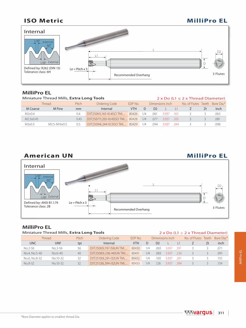
60°
1/8P
1/4P
L
L1D2
D
3 FlutesLe = Pitch x 3
L
L1D2
D
1/4P
1/8P
60°
3 Flutes
Le = Pitch x 3
311
Mill
Pro-
EL
Recommended Overhang
Internal
External
Defined by: ANSI B1.1:74Tolerance class: 2B
Internal
Internal
External
Recommended Overhang
Defined by: R262 (DIN 13)Tolerance class: 6H
Internal
MilliPro EL
MilliPro EL
American UN
ISO Metric
*Bore Diameter applies to smallest thread Dia.
MilliPro ELMiniature Thread Mills, Extra Long Tools 2 x Do (L1 ≤ 2 x Thread Diameter)
Thread Pitch Ordering Code EDP No. Dimensions inch No. of Flutes Teeth Bore Dia.*M Coarse M Fine mm Internal VTH D D2 L L1 Z Zt Inch
M2x0.4 0.4 D3T25061L165-I0.4ISO TML... 80426 1/4 .061 3.937 .165 3 3 .063
M2.5x0.45 0.45 D3T25077L205-I0.45ISO TML... 80428 1/4 .077 3.937 .205 3 3 .081
M3x0.5 M3.5-M16x0.5 0.5 D3T25094L244-I0.5ISO TML... 80429 1/4 .094 3.937 .244 3 3 .098
MilliPro ELMiniature Thread Mills, Extra Long Tools 2 x Do (L1 ≤ 2 x Thread Diameter)
Thread Pitch Ordering Code EDP No. Dimensions inch No. of Flutes Teeth Bore Dia.*UNC UNF tpi Internal VTH D D2 L L1 Z Zt inch
No.2-56 No.3-56 56 D3T25065L197-I56UN TML... 80430 1/4 .065 3.937 .197 3 3 .071No.4, No.5-40 No.6-40 40 D3T25083L236-I40UN TML... 80431 1/4 .083 3.937 .236 3 3 .091No.6, No.8-32 No.10-32 32 D3T25100L291-I32UN TML... 80432 1/4 .100 3.937 .291 3 3 .110No.8-32 No.10-32 32 D3T25126L394-I32UN TML... 80433 1/4 .126 3.937 .394 3 3 .134

D
L
L1
D2
Recommended Overhang4 Flutes
1/4P
1/8P
60°L
L1
D
D2
4-6 Flutes
LL1
D
D2
4-6 Flutes
312
Mill
Pro-
HD
Recommended Overhang
Internal
External
Defined by: ANSI B1.1:74Tolerance class: 2B
Internal
Left Hand Tool
MilliPro HDAmerican UN
Finish (Full Profile)Roughing (Partial Profile)
MilliPro HD Tools are left handed. For CNC use M04 code.
The work direction should be from the top to the bottom (Climb Milling).
1 Pitch
Two cutting teeth: Partial Profile for leading tooth followed by Full Profile for finishing.
*Bore Diameter applies to smallest thread Dia.
MilliPro HDMiniature Thread Mills for Hard Materials Up to 62HRc 3 x Do (L1 ≤ 3 x Thread Diameter)
Thread Pitch Ordering Code EDP No. Dimensions inch No. of Flutes Teeth Bore Dia.*UNC UNF tpi Internal VTH D D2 L L1 Z Zt inch
No.4-40, No.5-40 No.6-40 40 S2L25083L354-I40UN TM... 80952 1/4" .083 3.00 .380 4 2 .093No.5-40 No.6-40 40 S2L25096L394-I40UN TM... 80953 1/4" .096 3.00 .410 4 2 .104No.6-32, No.8-32 No.10-32 32 S2L25100L433-I32UN TM... 80954 1/4" .100 3.00 .460 4 2 .111No.8-32 No.10-32 32 S2L25126L512-I32UN TM... 80955 1/4" .126 3.00 .540 4 2 .136
1/4”x28 28 S2L25207L772-I28UN TM... 80956 1/4" .207 3.00 .810 5 2 .2195/16”x24 24 S2L31263L965-I24UN TM... 80957 5/16" .263 3.15 1.010 5 2 .272
1/4”x20 7/16”x20 20 S2L25192L780-I20UN TM... 80958 1/4" .192 3.00 .830 5 2 .2047/16”x14 14 S2L37354L131-I14UN TM... 80959 3/8" .354 4.00 1.390 6 2 .375
MilliPro HDMiniature Thread Mills for Hard Materials Up to 62HRc 2 x Do (L1 ≤ 2 x Thread Diameter)
Thread Pitch Ordering Code EDP No. Dimensions inch No. of Flutes Teeth Bore Dia.*UNC UNF tpi Internal VTH D D2 L L1 Z Zt inch
No.2-56 No.3-56 56 S2L25065L197-I56UN TM... 80936 1/4" .065 3.00 .210 4 2 .071No.3-48 No.4-48 48 S2L25075L236-I48UN TM... 80937 1/4" .075 3.00 .260 4 2 .083No.4-40, No.5-40 No.6-40 40 S2L25083L236-I40UN TM... 80938 1/4" .083 3.00 .260 4 2 .093No.5-40 No.6-40 40 S2L25096L283-I40UN TM... 80939 1/4" .096 3.00 .310 4 2 .104
No.8-36 36 S2L25130L343-I36UN TM... 80940 1/4" .130 3.00 .370 4 2 .140No.6-32, No.8-32 No.10-32 32 S2L25100L292-I32UN TM... 80941 1/4" .100 3.00 .320 4 2 .112No.8-32 No.10-32 32 S2L25126L394-I32UN TM... 80942 1/4" .126 3.00 .420 4 2 .138
No.10-32 32 S2L25146L394-I32UN TM... 80943 1/4" .146 3.00 .430 4 2 .1641/4”x28 28 S2L25207L520-I28UN TM... 80944 1/4" .207 3.00 .560 5 2 .219
No.10-24 5/16”x24 24 S2L25141L402-I24UN TM... 80945 1/4" .141 3.00 .440 4 2 .1545/16”x24 24 S2L31263L650-I24UN TM... 80946 5/16" .263 3.15 .690 5 2 .276
1/4”-20 7/16”x20 20 S2L25192L528-I20UN TM... 80947 1/4" .192 3.00 .580 5 2 .2057/16”x20 20 S2L37372L906-I20UN TM... 80948 3/8" .372 4.00 .960 6 2 .390
3/8”x16 16 S2L31301L776-I16UN TM... 80949 5/16" .301 3.15 .840 5 2 .3157/16”x14 14 S2L37354L917-I14UN TM... 80950 3/8" .354 4.00 .990 6 2 .3741/2”x13 13 S2L37390L101-I13UN TM... 80951 3/8" .390 4.00 1.080 6 2 .429

D
L
L1
D2
Recommended Overhang4 Flutes
1/4P
1/8P
60°L
L1
D
D2
4-6 Flutes
313
Mill
Pro-
HD
Recommended Overhang
Internal
External
Defined by: R262 (DIN 13)Tolerance class: 6H
Internal
Left Hand Tool
MilliPro HDISO Metric
Finish (F
ull Pro
file)
Roughing (Parti
al Pro
file)
MilliPro HD Tools are left handed. For CNC use M04 code.
The work direction should be from the top to the bottom (Climb Milling).
1 Pitch
Two cutting teeth: Partial Profile for leading tooth followed by Full Profile for finishing.
*Bore Diameter applies to smallest thread Dia.
MilliPro HDMiniature Thread Mills for Hard Materials Up to 62HRc 3 x Do (L1 ≤ 3 x Thread Diameter)
Thread Pitch Ordering Code EDP No. Dimensions inch No. of Flutes Teeth Bore Dia.*
M Coarse M Fine mm Internal VTH D D2 L L1 Z Zt inchM2x0.4 0.4 S2L25061L244-I0.4ISO TM... 80929 1/4 .061 2.99 .26 4 2 .063M2.5x0.45 0.45 S2L25077L303-I0.45ISO TM... 80930 1/4 .077 2.99 .32 4 2 .081M3x0.5 M3.5-M16x0.5 0.5 S2L25094L362-I0.5ISO TM... 80931 1/4 .094 2.99 .38 4 2 .101M4x0.7 0.7 S2L25124L484-I0.7ISO TM... 80932 1/4 .124 2.99 .51 4 2 .132M5x0.8 0.8 S2L25159L606-I0.8ISO TM... 80933 1/4 .159 2.99 .64 4 2 .169M6x1.0 M8-M40x1.0 1.0 S2L25189L728-I1.0ISO TM... 80934 1/4 .189 2.99 .77 5 2 .201M8x1.25 1.25 S2L31256L968-I1.25ISO TM... 80935 5/16 .256 3.15 1.02 5 2 .268
MilliPro HDMiniature Thread Mills for Hard Materials Up to 62HRc 2 x Do (L1 ≤ 2 x Thread Diameter)
Thread Pitch Ordering Code EDP No. Dimensions inch No. ofFlutes Teeth Bore Dia.*
M Coarse M Fine mm Internal VTH D D2 L L1 Z Zt InchM2x0.4 0.4 S2L25061L165-I0.4ISO TM... 80918 1/4 .061 2.99 .18 4 2 .063M2.2x0.45 0.45 S2L25065L181-I0.45ISO TM... 80919 1/4 .065 2.99 .20 4 2 .071M2.5x0.45 0.45 S2L25077L204-I0.45ISO TM... 80920 1/4 .077 2.99 .22 4 2 .081M3x0.5 M3.5-M16x0.5 0.5 S2L25094L244-I0.5ISO TM... 80921 1/4 .094 2.99 .27 4 2 .101M3.5x0.6 0.6 S2L25108L287-I0.6ISO TM... 80922 1/4 .108 2.99 .31 4 2 .116M4x0.7 0.7 S2L25124L326-I0.7ISO TM... 80923 1/4 .124 2.99 .36 4 2 .132M5x0.8 0.8 S2L25159L409-I0.8ISO TM... 80924 1/4 .159 2.99 .44 4 2 .169M6x1.0 M8-M40x1.0 1.0 S2L25189L492-I1.0ISO TM... 80925 1/4 .189 2.99 .53 5 2 .201M8x1.25 1.25 S2L31256L653-I1.25ISO TM... 80926 5/16 .256 3.15 .70 5 2 .268M10x1.5 M12-M48x1.50 1.50 S2L31308L818-I1.50ISO TM... 80927 5/16 .308 3.15 .88 6 2 .339M12x1.75 1.75 S2L37371L984-I1.75ISO TM... 80928 3/8 .371 3.98 1.05 6 2 .409

1/4P
1/8P
h
D2Le
L
D60°
314
Stra
ight
Internal
External
Defined by: ANSI B1.1:74Tolerance class: 2A/2B
External / Internal
StraightAmerican UN
Straight Flutes - InternalThread Pitch Ordering Code EDP No. Dimensions inch No. of Flutes Teeth
Min. Dia. tpi Internal VTS D D2 L Le Z Zt h inchNo.8 36 S1/8”.120”-I36UN TM... 80034 1/8 .120 1.654 .250 3 9 .016No.8 32 S1/8”.120”-I32UN TM... 80035 1/8 .120 1.654 .250 3 8 .0185/16” 32 S1/4”.240”-I32UN TM... 80036 1/4 .240 2.244 .562 3 18 .018No.12 28 S3/16”.145”-I28UN TM... 80037 3/16 .145 1.654 .321 3 9 .0217/16” 28 S5/16”.310”-I28UN TM3... 80038 5/16 .310 2.480 .786 3 22 .0217/16” 28 S5/16”.310”-I28UN TM5... 80441 5/16 .310 2.480 .786 5 22 .021No.12 24 S3/16”.160”-I24UN TM... 80039 3/16 .160 2.244 .333 3 8 .0241/4” 20 S3/16”.160”-I20UN TM... 80040 3/16 .160 2.244 .400 3 8 .0299/16” 20 S3/8”.370”-I20UN TM... 80041 3/8 .370 2.835 .900 5 18 .0295/16” 18 S1/4”.200”-I18UN TM... 80440 1/4 .200 2.244 .500 3 9 .0339/16” 18 S3/8”.370”-I18UN TM... 80043 3/8 .370 2.835 .944 5 17 .0333/8” 16 S1/4”.240”-I16UN TM... 80044 1/4 .240 2.244 .562 3 9 .03713/16” 16 S1/2”.470”-I16UN TM... 80045 1/2 .470 3.268 1.125 5 18 .0377/16” 14 S5/16”.310”-I14UN TM3... 80046 5/16 .310 2.480 .714 3 10 .0427/16” 14 S5/16”.310”-I14UN TM5... 80238 5/16 .310 2.480 .714 5 10 .0421/2” 13 S5/16”.310”-I13UN TM3... 80047 5/16 .310 2.480 .769 3 10 .0451/2” 13 S5/16”.310”-I13UN TM5... 80237 5/16 .310 2.480 .769 5 10 .0459/16” 12 S3/8”.370”-I12UN TM... 80048 3/8 .370 2.835 .917 5 11 .0491” 12 S1/2”.470”-I12UN TM... 80049 1/2 .470 3.268 1.167 5 14 .0495/8” 11 S3/8”.370”-I11UN TM... 80050 3/8 .370 2.835 .909 5 10 .0533/4” 10 S1/2”.470”-I10UN TM... 80051 1/2 .470 3.268 1.100 5 11 .0597/8” 9 S5/8”.620”-I9UN TM... 80442 5/8 .620 3.622 1.333 5 12 .0651” 8 S5/8”.620”-I8UN TM... 80053 5/8 .620 3.622 1.500 5 12 .0731 1/8” 7 S5/8”.620”-I7UN TM... 80054 5/8 .620 3.622 1.429 5 10 .0841 3/8” 6 S3/4”.745”-I6UN TM... 80055 3/4 .745 4.095 1.500 5 9 .0981 3/4” 5 S3/4”.745”-I5UN TM... 80057 3/4 .745 4.095 1.600 5 8 .1172” 4.5 S3/4”.745”-I4.5UN TM... 80058 3/4 .745 4.095 1.555 5 7 .130
Straight Flutes - ExternalThread Pitch Ordering Code EDP No. Dimensions inch No. of Flutes Teeth
Min. Dia. tpi External VTS D D2 L Le Z Zt h inchNo.6 32 S1/4”.240”-E32UN TM... 80026 1/4 .240 2.244 .562 3 18 .019No.12 28 S5/16”.310”-E28UN TM3... 80027 5/16 .310 2.480 .786 3 22 .022No.12 28 S5/16”.310”-E28UN TM5... 80408 5/16 .310 2.480 .786 5 22 .0221/4” 20 S3/8”.370”-E20UN TM... 80028 3/8 .370 2.835 .900 5 18 .0315/16” 18 S3/8”.370”-E18UN TM... 80029 3/8 .370 2.835 .944 5 17 .0343/8” 16 S1/2”.470”-E16UN TM... 80030 1/2 .470 3.268 1.125 5 18 .0389/16” 12 S1/2”.470”-E12UN TM... 80031 1/2 .470 3.268 1.167 5 14 .0511” 8 S5/8”.620”-E8UN TM... 80032 5/8 .620 3.622 1.500 5 12 .0771 3/8” 6 S5/8”.620”-E6UN TM... 80033 5/8 .620 3.622 1.500 5 9 .102

1/4P
1/8P
h
D2Le
L
D60°
315
Stra
ight
Internal
External
Defined by: R262 (DIN 13)Tolerance class: 6g/6H
External / Internal
ISO Metric Straight
Straight Flutes - InternalThread Pitch Ordering Code EDP No. Dimensions inch No. of Flutes Teeth
Min. Dia. mm Internal VTS D D2 L Le Z Zt h inchM4.5 0.75 S1/8”.120”-I0.75ISO TM... 80008 1/8 .120 1.496 .270 3 9 .017M8 0.75 S1/4”.240”-I0.75ISO TM... 80009 1/4 .240 2.244 .591 3 20 .017M5 0.80 S3/16”.145”-I0.8ISO TM... 80010 3/16 .145 1.654 .315 3 10 .018M6 1.00 S3/16”.160”-I1.0ISO TM... 80011 3/16 .160 1.654 .354 3 9 .023M12 1.00 S5/16”.310”-I1.0ISO TM3... 80012 5/16 .310 2.480 .787 3 20 .023M12 1.00 S5/16”.310”-I1.0ISO TM5... 80239 5/16 .310 2.480 .787 5 20 .023M8 1.25 S1/4”.200”-I1.25ISO TM... 80013 1/4 .200 2.244 .492 3 10 .029M10 1.50 S1/4".240"-I1.5ISO TM... 80014 1/4 .240 2.244 .591 3 10 .035M14 1.50 S3/8”.370”-I1.5ISO TM... 80015 3/8 .370 2.835 .945 5 16 .035M18 1.50 S1/2”.470”-I1.5ISO TM... 80016 1/2 .470 3.268 1.181 5 20 .035M12 1.75 S5/16”.310”-I1.75ISO TM3... 80017 5/16 .310 2.480 .758 3 11 .040M12 1.75 S5/16”.310”-I1.75ISO TM5... 80236 5/16 .310 2.480 .758 5 11 .040M16 2.00 S3/8”.370”-I2.0ISO TM... 80018 3/8 .370 2.835 .944 5 12 .046M18 2.00 S1/2”.470”-I2.0ISO TM... 80019 1/2 .470 3.268 1.181 5 15 .046M20 2.50 S1/2”.470”-I2.5ISO TM... 80020 1/2 .470 3.268 1.181 5 12 .058M24 3.00 S5/8”.620”-I3.0ISO TM... 80021 5/8 .620 3.622 1.417 5 12 .069M30 3.50 S5/8”.620”-I3.5ISO TM... 80022 5/8 .620 3.622 1.516 5 11 .081M36 4.00 S5/8”.620”-I4.0ISO TM... 80023 5/8 .620 3.622 1.575 5 10 .092M48 5.00 S3/4”.745”-I5.0ISO TM... 80024 3/4 .745 4.095 1.575 5 8 .116M64 6.00 S3/4”.745”-I6.0ISO TM... 80025 3/4 .745 4.095 1.417 5 6 .139
Straight Flutes - ExternalThread Pitch Ordering Code EDP No. Dimensions inch No. of Flutes Teeth
Min. Dia. mm External VTS D D2 L Le Z Zt h inchM3 0.50 S1/4”.240”-E0.5ISO TM... 80000 1/4 .240 2.244 .591 3 30 .012M4.5 0.75 S5/16”.310”-E0.75ISO TM3... 80001 5/16 .310 2.480 .610 3 26 .019M4.5 0.75 S5/16”.310”-E0.75ISO TM5... 80444 5/16 .310 2.480 .610 5 26 .019M6 1.00 S3/8”.370”-E1.0ISO TM... 80002 3/8 .370 2.835 .945 5 24 .025M10 1.50 S1/2”.470”-E1.5ISO TM... 80003 1/2 .470 3.268 1.181 5 20 .037M14 2.00 S1/2”.470”-E2.0ISO TM... 80004 1/2 .470 3.268 1.181 5 15 .050M24 3.00 S5/8”.620”-E3.0ISO TM... 80005 5/8 .620 3.622 1.417 5 12 075M36 4.00 S5/8”.620”-E4.0ISO TM... 80006 5/8 .620 3.622 1.575 5 10 .100M64 6.00 S3/4”.745”-E6.0ISO TM... 80007 3/4 .745 4.095 1.417 5 6 .149

R0.137P
h
R0.137P55°
D2Le
L
D
R 0.137P
h
R 0.137PD2
Le
L
D
55°
316
Stra
ight
Defined by: B.S.2779:1956 Tolerance class: Medium class
Internal
External
External / Internal
Internal
External
Defined by: B.S.84:1956, DIN 259, ISO228/1:1982Tolerance class: Medium class A
External / Internal
BSP
BSW
Straight
Straight
Straight FlutesThread Pitch Ordering Code EDP No. Dimensions inch No. of Flutes Teeth
Min. Dia. tpi External / Internal VTS D D2 L Le Z Zt h inch1/16” 28 S1/4”.240”-EI28BSP TM... 80076 1/4 .240 2.244 .571 3 16 .0231/4” 19 S5/16”.310”-EI19BSP TM3... 80073 5/16 .310 2.480 .737 3 14 .0341/4” 19 S5/16”.310”-EI19BSP TM5... 80234 5/16 .310 2.480 .737 5 14 .0341/2” 14 S1/2”.470”-EI14BSP TM... 80074 1/2 .470 3.268 1.143 5 16 .0461” 11 S5/8”.620”-EI11BSP TM... 80075 5/8 .620 3.622 1.364 5 15 .058
Straight FlutesThread Pitch Ordering Code EDP No. Dimensions inch No. of Flutes Teeth
Min. Dia. tpi External / Internal VTS D D2 L Le Z Zt h inch1/4” 20 S3/16”.160”-EI20BSW TM... 80059 3/16 .160 1.654 .400 3 8 .0325/16” 18 S1/4”.200”-EI18BSW TM... 80060 1/4 .200 2.244 .444 3 8 .0353/8” 16 S1/4”.240”-EI16BSW TM... 80061 1/4 .240 2.244 .562 3 9 .0407/16” 14 S5/16”.310”-EI14BSW TM3... 80062 5/16 .310 2.480 .714 3 10 .0467/16” 14 S5/16”.310”-EI14BSW TM5... 80232 5/16 .310 2.480 .714 5 10 .0461/2” 12 S5/16”.310”-EI12BSW TM3... 80063 5/16 .310 2.480 .750 3 9 .0531/2” 12 S5/16”.310”-EI12BSW TM5... 80447 5/16 .310 2.480 .750 5 9 .0535/8” 11 S3/8”.370”-EI11BSW TM... 80064 3/8 .370 2.835 .909 5 10 .0583/4” 10 S1/2”.470”-EI10BSW TM... 80065 1/2 .470 3.268 1.100 5 11 .0647/8” 9 S1/2”.470”-EI9BSW TM... 80066 1/2 .470 3.268 1.111 5 10 .0711” 8 S5/8”.620”-EI8BSW TM... 80067 5/8 .620 3.622 1.500 5 12 .0801 1/8” 7 S5/8”.620”-EI7BSW TM... 80068 5/8 .620 3.622 1.429 5 10 .0911 3/8” 6 S5/8”.620”-EI6BSW TM... 80069 5/8 .620 3.622 1.500 5 9 .1071 5/8” 5 S3/4”.745”-EI5BSW TM... 80070 3/4 .745 4.095 1.600 5 8 .1281 7/8” 4.5 S3/4”.745”-EI4.5BSW TM... 80071 3/4 .745 4.095 1.555 5 7 .142
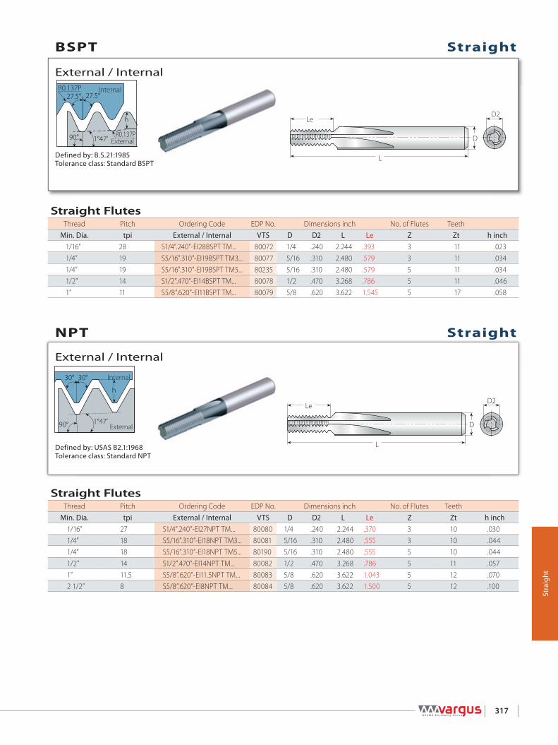
D2Le
L
D
h
R0.137P
R0.137P27.5° 27.5°
1°47’90°
hD2
90°
30° 30°
1°47’
Le
L
D
317
Stra
ight
Defined by: USAS B2.1:1968Tolerance class: Standard NPT
Internal
External
External / Internal
Defined by: B.S.21:1985Tolerance class: Standard BSPT
Internal
External
External / Internal
Straight
Straight
NPT
BSPT
Straight FlutesThread Pitch Ordering Code EDP No. Dimensions inch No. of Flutes Teeth
Min. Dia. tpi External / Internal VTS D D2 L Le Z Zt h inch1/16” 27 S1/4”.240”-EI27NPT TM... 80080 1/4 .240 2.244 .370 3 10 .0301/4” 18 S5/16”.310”-EI18NPT TM3... 80081 5/16 .310 2.480 .555 3 10 .0441/4” 18 S5/16”.310”-EI18NPT TM5... 80190 5/16 .310 2.480 .555 5 10 .0441/2” 14 S1/2”.470”-EI14NPT TM... 80082 1/2 .470 3.268 .786 5 11 .0571” 11.5 S5/8”.620”-EI11.5NPT TM... 80083 5/8 .620 3.622 1.043 5 12 .0702 1/2” 8 S5/8”.620”-EI8NPT TM... 80084 5/8 .620 3.622 1.500 5 12 .100
Straight FlutesThread Pitch Ordering Code EDP No. Dimensions inch No. of Flutes Teeth
Min. Dia. tpi External / Internal VTS D D2 L Le Z Zt h inch1/16” 28 S1/4”.240”-EI28BSPT TM... 80072 1/4 .240 2.244 .393 3 11 .0231/4” 19 S5/16”.310”-EI19BSPT TM3... 80077 5/16 .310 2.480 .579 3 11 .0341/4” 19 S5/16”.310”-EI19BSPT TM5... 80235 5/16 .310 2.480 .579 5 11 .0341/2” 14 S1/2”.470”-EI14BSPT TM... 80078 1/2 .470 3.268 .786 5 11 .0461” 11 S5/8”.620”-EI11BSPT TM... 80079 5/8 .620 3.622 1.545 5 17 .058

h
D2Le
L
D
90°
30° 30°
1°47’
R0.107P
R0.107P
h
D2Le
L
D
80°
318
Stra
ight
Defined by: DIN 40430Tolerance class: Standard
Internal
External
External / Internal
Defined by: ANSI 1.20.3-1976Tolerance class: Standard NPTF
Internal
External
External / Internal
Pg
NPTF
Straight
Straight
Straight FlutesThread Pitch Ordering Code EDP No. Dimensions inch No. of Flutes Teeth
tpi External / Internal VTS D D2 L Le Z Zt h inchPg7 20 S5/16".310"-EI20PG TM3... 80090 5/16 .310 2.480 .750 3 15 0.024Pg7 20 S5/16".310"-EI20PG TM5... 80448 5/16 .310 2.480 .750 5 15 0.024Pg9, 11, 13.5, 16 18 S3/8".370"-EI18PG TM... 80091 3/8 .370 2.835 .944 5 17 0.026Pg21, 29, 36, 42, 48 16 S1/2".470"-EI16PG TM... 80092 1/2 .470 3.268 1.125 5 18 0.030
Straight FlutesThread Pitch Ordering Code EDP No. Dimensions inch No. of Flutes Teeth
Min. Dia. tpi External / Internal VTS D D2 L Le Z Zt h inch1/16” 27 S1/4”.240”-EI27NPTF TM... 80085 1/4 .240 2.244 .370 3 10 .0301/4” 18 S5/16”.310”-EI18NPTF TM3... 80086 5/16 .310 2.480 .555 3 10 .0441/4” 18 S5/16”.310”-EI18NPTF TM5... 80233 5/16 .310 2.480 .555 5 10 .0441/2” 14 S1/2”.470”-EI14NPTF TM... 80087 1/2 .470 3.268 .786 5 11 .0571” 11.5 S5/8”.620”-EI11.5NPTF TM... 80088 5/8 .620 3.622 1.043 5 12 .0702 1/2” 8 S5/8”.620”-EI8NPTF TM... 80089 5/8 .620 3.622 1.500 5 12 .100
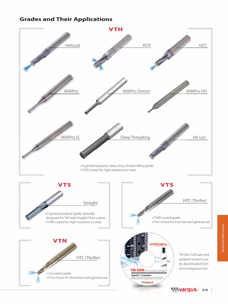
319
Tech
nica
l Inf
orm
atio
n
• A general-purpose, heavy duty thread milling grade • TiCN coated for high resistance to wear
He-LexMilliPro EL Deep Threading
MilliPro HDMilliPro MilliPro Dental
HCCHCRHelicool
Grades and Their Applications
TM Gen Software and updated versions canbe downloaded fromwww.vargususa.com
• TiAIN coated grade • First choice for Cast iron and general use
VTS
HTC (Thriller)
• Uncoated grade • First choice for Aluminium and general use
VTN
HTC (Thriller)
• A general-purpose grade, specially designed for TM Solid Straight Flute cutters • TiAlN coated for high resistance to wear
VTS
Straight
VTH

2
1 36 4
5
320
Tech
nica
l Inf
orm
atio
n
Tool entry along tangential arc* Recommendation: At tool entry, set the Feed f [inch/tooth] to 70% lower
than the threading Feed.
Example:Threading Feed: 0.012[inch/tooth]Tool entry Feed: 0.0035[inch/tooth]
Cutting Speeds Vc [ft/min] and Feed f [inch/tooth] (Not Including HTC & MilliPro HD)
Material Group Va
rdex
No.
Material
Hardness Brinell
HB
Vc [ft/min] Feed [inch/tooth]
Helicool, HCR, HCC, He-Lex, Sraight, Deep Threading
MilliProHe-Lex Straight
Deep Threading
HelicoolHCCHCR
MilliPro
VTH VTS VTH
PSteel
1Unalloyed steel
Low carbon (C=0.1-0.25%) 125 262-820 164-590 197-394 .0012-.0059 .0004-.0039 .0039-.0138 .001-.0118 .0008-.0063
2 Medium carbon (C=0.25-0.55%) 150 262-754 164-459 197-394 .0012-.0039 .0004-.0031 .0031-.0118 .0008-.0102 .0008-.0063
3 High Carbon (C=0.55-0.85%) 170 262-656 164-394 197-295 .0012-.0031 .0004-.0024 .0031-.0118 .0008-.0091 .0008-.0063
4Low alloy steel(alloying elements ≤5%)
Non hardened 180 197-590 197-558 197-295 .0012-.0039 .0012-.0028 .0031-.0118 .0008-.0087 .0006-.0063
5 Hardened 275 197-558 197-525 164-262 .0012-.0028 .0012-.0028 .0031-.0118 .0004-.0059 .0006-.0028
6 Hardened 350 197-525 197-492 164-262 .0004-.0012 .0002-.0004 .002-.0059 .0004-.0039 .0006-.0012
7 High alloy steel(alloying elements>5%)
Annealed 200 131-328 131-295 164-262 .0012-.002 .0004-.0012 .0039-.0094 .0004-.0051 .0006-.0035
8 Hardened 325 98-262 98-230 164-262 .0004-.0012 .0002-.0004 .002-.0059 .0004-.0047 .0006-.0012
9Cast steel
Low alloy (alloying elements <5%) 200 262-820 230-656 230-295 .0012-.0039 .0004-.0012 .0031-.0118 .0004-.0059 .0006-.0063
10 High alloy (alloying elements >5%) 225 197-558 197-492 197-262 .0004-.0012 .0002-.0004 .002-.0059 .0004-.0039 .0006-.0012
MStainless
Steel
11 Stainless steel Feritic
Non hardened 200 197-492 164-459 197-295 .0016-.0039 .0004-.002 .0043-.0138 .0004-.0051 .0006-.0063
12 Hardened 330 197-394 164-361 164-262 .0004-.002 .0002-.0004 .002-.0094 .0004-.0047 .0006-.0012
13 Stainless steel Austenitic
Austenitic 180 197-459 197-426 197-295 .0016-.0039 .0003-.0008 .0043-.0138 .0004-.0047 .0006-.0063
14 Super Austenitic 200 197-426 164-394 164-262 .0016-.0039 .0003-.0008 .0043-.0138 .0004-.0039 .0006-.0063
15 Stainless steel Cast Feritic
Non hardened 200 197-525 164-492 197-295 .0016-.0039 .0004-.0012 .0043-.0138 .0004-.0059 .0006-.0063
16 Hardened 330 197-361 164-328 164-262 .0012-.002 .0002-.0004 .0039-.0094 .0004-.0039 .0006-.0012
17 Stainless steelCast austenitic
Austenitic 200 197-492 164-459 197-295 .0016-.0039 .0004-.0012 .0043-.0138 .0004-.0047 .0006-.0063
18 Hardened 330 197-328 164-295 164-262 .0012-.002 .0002-.0004 .0039-.0094 .0004-.0039 .0006-.0012
KCast Iron
28 Malleable Cast iron
Ferritic (short chips) 130 197-230 197-492 164-262 .0004-.0012 .0003-.0008 .002-.0059 .0004-.0059 .0006-.0012
29 Pearlitic (long chips) 230 197-492 262-328 197-295 .0012-.002 .0002-.0004 .0039-.0094 .0004-.0047 .0008-.0047
30Grey cast iron
Low tensile strength 180 230-525 164-459 230-328 .0008-.0039 .0003-.0008 .0035-.0098 .0004-.0051 .0008-.0063
31 High tensile strength 260 131-394 131-361 197-295 .0012-.002 .0002-.0004 .0039-.0094 .0004-.0047 .0008-.0047
32Nodular SG iron
Feritic 160 131-361 131-328 230-328 .002-.0039 .0003-.0008 .0035-.0098 .0004-.0051 .0008-.0063
33 Pearlitic 260 131-328 131-295 197-295 .0012-.002 .0002-.0004 .0039-.0094 .0004-.0047 .0008-.0047
N(K)Non-
Ferrous Metals
34 Aluminium alloys Wrought
Non aging 60 66-984 49-820 197-820 .0039-.0098 .002-.0059 .0047-.0157 .0016-.0157 .001-.0059
35 Aged 100 49-820 33-722 197-492 .0039-.0079 .0012-.0039 .0039-.0126 .0012-.0142 .001-.0063
36Aluminium alloys
Cast 75 33-656 262-492 197-820 .0039-.0079 .002-.0059 .0039-.0126 .0012-.0142 .001-.0063
37 Cast & aged 90 39-722 295-525 197-492 .0039-.0059 .0012-.0039 .0039-.0118 .0039-.0118 .0006-.0063
38 Aluminium alloys Cast Si 13-22% 130 66-984 49-820 820 .0039-.0079 .002-.0059 .0039-.0126 .0012-.0142 .0012-.0059
39 Copper andcopper alloys
Brass 90 66-984 49-820 197-820 .0039-.0098 .002-.0059 .0047-.0157 .0016-.0169
40 Bronze and non leaded copper 100 49-820 33-722 197-492 .0039-.0079 .0012-.0039 .0039-.0126 .0012-.0142 .0012-.0059
S(M)Heat
ResistantMaterial
19
High temperaturealloys
Annealed (Iron based ) 200 98-197 98-164 197 .0016-.0039 .0003-.0008 .0043-.0138 .0003-.0035 .0006-.0063
20 Aged (Iron based) 280 66-164 66-131 164 .0004-.0012 .0002-.0004 .002-.0059 .0002-.0028 .0006-.0012
21 Annealed (Nickel or Cobalt based) 250 49-115 49-98 115 .0004-.0012 .0002-.0004 .002-.0059 .0002-.0024 .0006-.0012
22 Aged (Nickel or Cobalt based) 350 49-98 49-82 98 .0004-.0012 .0002-.0004 .002-.0059 .0002-.0024 .0006-.0012
23Titanium alloys
Pure 99.5 Ti 400Rm 131-262 98-230 98-164 .0012-.002 .0003-.0008 .0039-.0094 .0002-.0028 .0006-.0028
24 α+β alloys 1050Rm 66-164 66-148 82-115 .0012-.002 .0003-.0008 .0039-.0094 .0002-.0028 .0006-.0028
H(K)Hardened Material
25Extra hard steel Hardened & tempered
45-50HRc 49-148 49-115 148 .0002-.0004 .0001-.0002 .001-.0024 .0002-.0016 .0004-.0016
26 51-55HRc 49-131 49-98 98 .0002-.0004 .0001-.0002 .001-.0024 .0002-.0016 -

321
Tech
nica
l Inf
orm
atio
n
Vc - Cutting Speed [ft/min] fb (Drilling) - Feed per Revolution [inch/rev] fz (Threading) - Feed per Tooth [inch/tooth]
HTC Recommended Grades, Cutting Speed and Feed
Material Group
Material
Hardness
Brinell HB
Strength(N-mm2)
Vc[ft/min] fb[inch/rev] fz[inch/tooth]
VTN VTS ≤.24 inch ≤.47 inch ≤.24 inch ≤47 inch
KCast Iron
Cast IronGrey cast iron ≤150 ≤500 165-260 260-390 .004-.006 .006-.009 .001-.002 .002-.004
Grey cast iron, heat treated 150-300 500-1000 165-260 260-390 .004-.006 .006-.009 0.02-0.05 .002-.004
Spher. graph. Cast Iron ≤200 ≤700 165-260 260-390 .004-.006 .006-.009 0.02-0.05 .002-.004
Copper Short Chips, Brass, Bronze, Red Brass ≤200 ≤700 330-980 — .004-.012 .002-.004 .001-.002 .002-.004
N(K)Non-
Ferrous Metals
Aluminium/Magnesium
Aluminium, Magnesium non-alloy ≤100 ≤350 330-1310 330-1310 .004-.010 .010-.012 .001-.002 .002-.004
Aluminium, Wrought Alloy, Breaking Strain (A5) < 14% ≤180 ≤600 330-1310 330-1310 .004-.010 .010-.012 .001-.002 .002-.004
Aluminium, Wrought Alloy, Breaking Strain (A5) ≥ 14% ≤180 ≤600 330-1310 330-1310 .001-.002 .002-.005 .001-.002 .002-.004
Aluminium, Cast Alloy, Si<10% ≤180 ≤600 330-980 330-1310 .004-.010 .010-.012 .001-.002 .002-.004
Aluminium, Cast Alloy, Si≥10% ≤180 ≤600 — 330-980 .004-.010 .010-.012 .001-.002 .002-.004
PlasticThermoplastics — — 195-390 195-390 .004-.010 .010-.012 .001-.002 .002-.004
Thermosetting Plastic — — 195-330 195-330 .004-.010 .010-.012 .001-.002 .002-.004
Fibre Reinforce Plastic — — 130-195 195-260 .004-.006 .006-.009 .001-.002 .002-.004
MilliPro HDCutting Speeds Vc [ft/min] and Feed f [inch/tooth]
Material Group Va
rdex
No.
MaterialHardness Brinell HB
Vc [ft/min] Feed f [inch/tooth] by Cutting Dia.=D2
VTH .06-.10 .10-.20 .20-.30 .30-.35 .35-.45
PSteel
6 Low alloy steel(alloying elements≤5%) Hardened 350 82-525
.0016 .0020 .0024 .0028 .0031
8 High alloy steel(alloying elements>5%) Hardened 325 82-590
MStainless
Steel
12 Stainless steel Feritic Hardened 330 82-394
.0016 .0020 .0024 .0028 .003116 Stainless steel
Cast Feritic Hardened 330 82-361
18 Stainless steelCast Austenitic Hardened 330 82-328
KCast Iron
28Malleable cast iron
Ferritic (short chips) 130 82-525 .0020 .0024 .0028 .0031 .0039
29 Pearlitic (long chips) 230 82-492 .0016 .0020 .0024 .0028 .0031
30Grey cast iron
Low tensile strength 180 82-426 .0020 .0024 .0028 .0031 .0039
31 High tensile strength 260 82-328 .0016 .0020 .0024 .0028 .0031
32Nodular SG iron
Feritic 160 82-410 .0016 .0020 .0024 .0028 .0035
33 Pearlitic 260 82-295 .0012 .0016 .0020 .0024 .0028
S(M)Heat
ResistantMaterial
21 High temperaturealloys
Annealed (Nickel or Cobalt based) 250 49-115
.0012 .0016 .0020 .0024 .002822 Aged (Nickel or Cobalt based) 350 49-98
23Titanium alloys
Pure 99.5 Ti 400Rm 82-230
24 α+β alloys 1050Rm 82-164
H(K)Hardened Material
25
Extra hard steel Hardened & tempered
45-50HRc 82-230 .0016 .0020 .0024 .0028 .0031
26 51-55HRc 82-197 .0012 .0016 .0020 .0024 .0028
27 56-62HRc 82-164 .0008 .0012 .0016 .0020 .0024

322
Tech
nica
l Inf
orm
atio
n
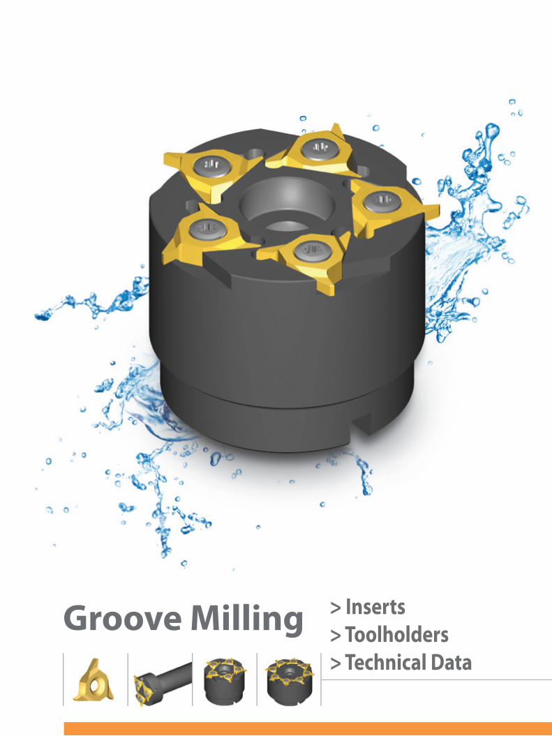
> Inserts> Toolholders> Technical Data
Groove Milling
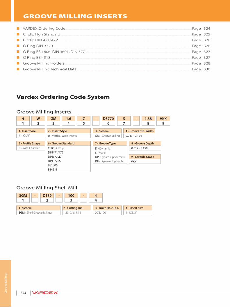
324
Vardex Ordering Code System
Groove Milling Inserts
GROOVE MILLING INSERTS
VARDEX Ordering Code.................................................................................................................................................................Page 324
Circlip Non Standard ......................................................................................................................................................................Page 325
Circlip DIN 471/472 ..........................................................................................................................................................................Page 326
O Ring DIN 3770 ................................................................................................................................................................................Page 326
O Ring BS 1806, DIN 3601, DIN 3771 .....................................................................................................................................Page 327
O Ring BS 4518 ...................................................................................................................................................................................Page 327
Groove Milling Holders ..................................................................................................................................................................Page 328
Groove Milling Technical Data ..................................................................................................................................................Page 330
4 - Insert Size4 - IC1/2”
3 - Drive Hole Dia.0.75, 100
2 - Cutting Dia.1.89, 2.48, 3.15
1- SystemSGM - Shell Groove Milling
44
-1003
-D1892
-SGM1
Groove Milling Shell Mill
9 - Carbide GradeVKX
8 - Groove Depth0.012 - 0.150
4 - Groove Std. Width0.043 - 0.124
7 - Groove Type
D - DynamicS - StaticDP- Dynamic pneumaticDH- Dynamic hydraulic
3 - SystemGM - Groove Milling
6 - Groove Standard
CIRC - CirclipDIN471/472DIN3770DDIN3770SBS1806BS4518
2 - Insert StyleW -Vertical Wide Inserts
5 - Profile ShapeC - With Chamfer
1- Insert Size4 - IC1/2”
VKX9
1.388
-S7
D37706
-C5
1.64
GM3
W2
41
Gro
ove
Mill
ing

325
Vertical SGMInsert Size Ordering Code Dimensions inch α
IC L inch W R t1 Toolholder
1/2” 0.87
4WGM.031C-CIRC-.06... 0.31 0.005 0.050
45° SGM-D..-..-4
4WGM.047C-CIRC-.083... 0.47 0.010 0.0754WGM.058C-CIRC-.083... 0.58 0.010 0.0754WGM.062C-CIRC-.102... 0.62 0.010 0.0944WGM.072C-CIRC-.102... 0.72 0.010 0.0944WGM.078C-CIRC-.102... 0.78 0.010 0.0944WGM.088C-CIRC-.102... 0.88 0.010 0.0944WGM.094C-CIRC-.157... 0.94 0.010 0.1504WGM.097C-CIRC-.157... 0.97 0.010 0.1504WGM.105C-CIRC-.157... 0.105 0.010 0.1504WGM.110C-CIRC-.157... 0.110 0.010 0.1504WGM.122C-CIRC-.157... 0.122 0.010 0.1504WGM.125C-CIRC-.157... 0.125 0.010 0.1504WGM.142C-CIRC-.157... 0.142 0.015 0.1504WGM.156C-CIRC-.157... 0.156 0.010 0.150
Gro
ove
Mill
ing
Vertical SGM
View A
Enlarged view A
External / Internal
Circlip Non Standard
W
I.C.R
αt1

326
St. = Static Dy. = Dynamic
* Standard groove width in mm.
Vertical SGMInsert Size Ordering Code Groove Std. αIC L inch St.Dy *m(H13) W t R1 R2 Toolholder
1/2” 0.87
St.
4WGM1.6C-D3770S-1.38... 1.60 0.078 0.054 0.010 0.004
75° SGM-D..-..-4
4WGM2.0C-D3770S-1.72... 2.00 0.093 0.068 0.010 0.0044WGM2.5C-D3770S-2.15... 2.50 0.119 0.085 0.010 0.0044WGM3.15C-D3770S-2.70... 3.15 0.148 0.106 0.024 0.008
Dy.4WGM1.6C-D3770D-1.47... 1.60 0.078 0.058 0.010 0.0044WGM2.0C-D3770D-1.83... 2.00 0.093 0.072 0.010 0.004
Vertical SGMInsert Size Ordering Code Groove Std. α
IC L inch *m(H13) W t1 Toolholder
1/2” 0.87
4WGM1.1C-D471/472-0.35... 1.10 0.047 0.012
45° SGM-D..-..-4
4WGM1.1C-D471/472-0.40... 1.10 0.047 0.0164WGM1.3C-D471/472-0.50... 1.30 0.055 0.0164WGM1.3C-D471/472-0.55... 1.30 0.055 0.024WGM1.6C-D471/472-0.70... 1.60 0.067 0.0244WGM1.6C-D471/472-0.85... 1.60 0.067 0.0314WGM1.6C-D471/472-1.00... 1.60 0.067 0.0354WGM1.85C-D471/472-1.25... 1.85 0.076 0.0434WGM1.85C-D471/472-1.00... 1.85 0.076 0.0354WGM2.15C-D471/472-1.50... 2.15 0.088 0.0554WGM2.65C-D471/472-1.50... 2.65 0.108 0.0554WGM2.65C-D471/472-1.75... 2.65 0.108 0.0634WGM3.15C-D471/472-1.75... 3.15 0.128 0.063
* Standard groove width in mm.
Gro
ove
Mill
ing
t1 α
I.C.
W
mm
t1 α
I.C.
W
mm
R1 R2
Vertical SGM
View A
Enlarged view A
External / Internal
Circlip DIN 471/472
Vertical SGM
View A
Enlarged view A
External / Internal
O Ring DIN 3770

327
* Standard groove width in mm.St. = StaticDy. = Dynamic
Vertical SGMInsert Size Ordering Code Groove Std. αIC L inch St.Dy *m(H13) W t R1 R2 Toolholder
1/2” 0.87St.
4WGM1.80C-BS1806S-1.3... 1.80 0.093 0.051 0.008 0.024
75° SGM-D..-..-44WGM2.65C-BS1806S-2.0... 2.65 0.141 0.079 0.008 0.024
Dy.4WGM1.80C-BS1806D-1.57... 1.80 0.093 0.061 0.008 0.0244WGM2.65C-BS1806D-2.38... 2.65 0.141 0.091 0.008 0.024
* Standard groove width in mm.St. = StaticDyP = Dynamic pneumaticDyH = Dynamic hydraulic
Vertical SGMInsert Size Ordering Code Groove Std. αIC L inch St.Dy *m(H13) W t R1 R2 Toolholder
1/2” 0.87
St.4WGM1.6C-BS4518S-1.25... 1.60 0.093 0.049 0.020 0.008
75° SGM-D..-..-4
4WGM2.4C-BS4518S-1.95... 2.40 0.125 0.077 0.020 0.0084WGM3.0C-BS4518S-2.51... 3.00 0.148 0.099 0.039 0.008
DyP4WGM2.4C-BS4518DP-2.20... 2.40 0.129 0.087 0.020 0.0084WGM3.0C-BS4518DP-2.77... 3.00 0.160 0.109 0.039 0.008
DyH4WGM2.4C-BS4518DH-2.09... 2.40 0.129 0.082 0.020 0.0084WGM3.0C-BS4518DH-2.60... 3.00 0.160 0.102 0.039 0.008
Gro
ove
Mill
ing
I.C.
R1 R2
tα
W
mm
I.C.
R1 R2
tα
W
m m
Vertical SGM
View A
Enlarged view A
External / Internal
O Ring BS 1806, DIN3601, DIN 3771
Vertical SGM
View A
Enlarged view A
External / Internal
BS 4518

328
Multi Insert Holders (5) Spare Parts
Insert Size Ordering Code EDP
No. Dimensions inch
IC D2 t max d(H7) D1 H Insert Screw Torx Key Holder Screw1/2” SGM-D250-0.75-4 67721 2.48 0.137 3/4 2.342 1.614 SN4T-90 HK4T 3/8 - 24
Toolholders
Toolholders
Multi Insert Holders (3) Spare Parts
Insert Size Ordering Code EDP
No. Dimensions inch
IC D2 t max L L1 d(H7) D1 Insert Screw Torx Key1/2” SGM-D189-100-4 67717 1.89 0.137 5.0 0.874 1.0 1.574 SN4T-90 HK4T
Gro
ove
Mill
ing
D2t max.
D1
L
d
L1
D2 t max.H
D1 d(H7)

329
Toolholders
Multi Insert Holders (8) Spare Parts
Insert Size Ordering Code EPD
No. Dimensions inch
IC D2 t max d(H7) D1 H Insert Screw Torx Key Holder Screw1/2” SGM-D300-100-4 67729 3.15 0.137 1.0 2.834 1.968 SN4T-90 HK4T 1/2 - 20
Gro
ove
Mill
ing
D2t max H
D1d(H7)
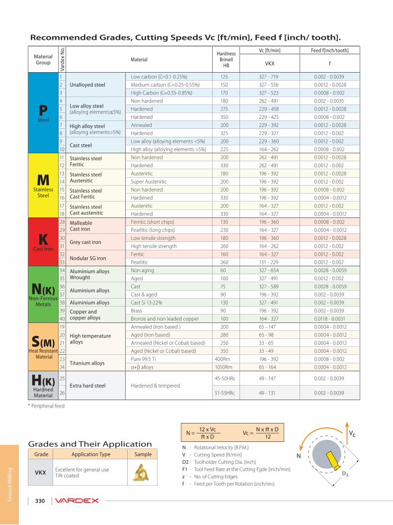
330
Grades and Their ApplicationVc =
12N x π x D
π x D12 x Vc
N =
* Peripheral feed
N - Rotational Velocity [R.P.M.]V - Cutting Speed [ft/min]D2 - Toolholder Cutting Dia. [inch]F1 - Tool Feed Rate at the Cutting Egde [inch/min]z - No. of Cutting Edgesf - Feed per Tooth per Rotation [inch/rev]
Grade Application Type Sample
VKX Excellent for general use TiN coated
Recommended Grades, Cutting Speeds Vc [ft/min], Feed f [inch/ tooth].
Material Group
Vard
ex N
o.Material
Hardness Brinell
HB
Vc [ft/min] Feed f[inch/tooth]
VKX f
PSteel
1Unalloyed steel
Low carbon (C=0.1-0.25%) 125 327 - 719 0.002 - 0.00392 Medium carbon (C=0.25-0.55%) 150 327 - 556 0.0012 - 0.00283 High Carbon (C=0.55-0.85%) 170 327 - 523 0.0008 - 0.0024
Low alloy steel(alloying elements≤5%)
Non hardened 180 262 - 491 0.002 - 0.00355 Hardened 275 229 - 458 0.0012 - 0.00286 Hardened 350 229 - 425 0.0008 - 0.0027 High alloy steel
(alloying elements>5%) Annealed 200 229 - 392 0.0012 - 0.0028
8 Hardened 325 229 - 327 0.0012 - 0.0029
Cast steel Low alloy (alloying elements <5%) 200 229 - 360 0.0012 - 0.002
10 High alloy (alloying elements >5%) 225 164 - 262 0.0008 - 0.002
MStainless
Steel
11 Stainless steel Feritic
Non hardened 200 262 - 491 0.0012 - 0.002812 Hardened 330 262 - 491 0.0012 - 0.00213 Stainless steel
Austenitic Austenitic 180 196 - 392 0.0012 - 0.0028
14 Super Austenitic 200 196 - 392 0.0012 - 0.00215 Stainless steel
Cast Feritic Non hardened 200 196 - 392 0.0008 - 0.002
16 Hardened 330 196 - 392 0.0004 - 0.001217 Stainless steel
Cast austenitic Austenitic 200 164 - 327 0.0012 - 0.002
18 Hardened 330 164 - 327 0.0004 - 0.0012
KCast Iron
28 Malleable Cast iron
Ferritic (short chips) 130 196 - 360 0.0008 - 0.00229 Pearlitic (long chips) 230 164 - 327 0.0004 - 0.001230
Grey cast iron Low tensile strength 180 196 - 360 0.0012 - 0.0028
31 High tensile strength 260 164 - 262 0.0012 - 0.00232
Nodular SG iron Feritic 160 164 - 327 0.0012 - 0.002
33 Pearlitic 260 131 - 229 0.0012 - 0.002
N(K)Non-Ferrous
Metals
34 Aluminium alloys Wrought
Non aging 60 327 - 654 0.0028 - 0.005935 Aged 100 327 - 491 0.0012 - 0.00236
Aluminium alloys Cast 75 327 - 589 0.0028 - 0.0059
37 Cast & aged 90 196 - 392 0.002 - 0.003938 Aluminium alloys Cast Si 13-22% 130 327 - 491 0.002 - 0.003939 Copper and
copper alloys Brass 90 196 - 392 0.002 - 0.0039
40 Bronze and non leaded copper 100 164 - 327 0.0118 - 0.0031
S(M)Heat Resistant
Material
19
High temperaturealloys
Annealed (Iron based ) 200 65 - 147 0.0004 - 0.001220 Aged (Iron based) 280 65 - 98 0.0004 - 0.001221 Annealed (Nickel or Cobalt based) 250 33 - 65 0.0004 - 0.001222 Aged (Nickel or Cobalt based) 350 33 - 49 0.0004 - 0.001223
Titanium alloys Pure 99.5 Ti 400Rm 196 - 392 0.0008 - 0.002
24 α+β alloys 1050Rm 65 - 164 0.0004 - 0.0012
H(K)Hardned Material
25Extra hard steel Hardened & tempered
45-50HRc 49 - 147 0.002 - 0.0039
26 51-55HRc 49 - 131 0.002 - 0.0039
Gro
ove
Mill
ing
D2
N
Vc

331
Notes

332
Notes

NEW SOLID CARBIDE TOOLSHELICOOL FAMILY
MILLIPRO FAMILY DEEP THREADING HE-LEX
NEW SOLID CARBIDE TOOLSNEW IN THIS CATALOG
MULTI+ INSERTS MINI-3 IC4.0 TMSD
V6 INSERTS
MiTM FAMILY
DEEP THREADING HE-LEX
Helicool Helical Flutes with Thru-Hole Coolant
Helicool-R (HCR) Radial Coolant
Helicool-C (HCC) Thread & Chamfer in One Tool
Thriller (HTC) Drill, Thread & Chamfer in One Tool
A Revolutionary 6 Cutting Corners System
Indexable Threading Insert for Small Bores
Multi-Flute Indexable Thread Milling for Fast Machining
For the complete list of VARDEX worldwide distributors, visit our website at www.vargususa.com
Thread Mills for Deep HolesImproved Design for Multi-Tooth Inserts
Miniature Thread Mills Long Reaching up to 3xDo Economical Tool for Thru-Holes
See Page 294
See Page 302See Page 305See Page 306
See Pages 17-95
See Pages 17-95
See Pages 17-95
See Pages 255-273
See Pages 275-289
M+ T+ Z+
A d v a n c e d T h r e a d i n g S o l u t i o n s
V A R D E X W O R L D W I D E
ChinaVargus China
Neumo-Vargus (Shanghai) Trading Co. Ltd. +86 215239 5005/6/9 [email protected]
DenmarkVargus Denmark
Damstahl Tooling A/S +45 8794 4100 [email protected]
France Vargus France +33 1 4601 7060 [email protected]
Germany Vargus Germany +49 7043 36 161 [email protected]
India Vargus India +91 98990 73393 [email protected]
IsraelVargus Israel
Neumo-Vargus Marketing Ltd +972 3 537 3275 [email protected]
PolandVargus Poland
Neumo-Polska Sp. Z.O.O.
+48 46 834 9904
+48 603 888 [email protected]
SwitzerlandVargus Switzerland
Werkzeugtechnik (Snel AG) +41 41784 2121 [email protected]
United Kingdom Vargus Tooling UK Ltd. +1 44 1952 583 222 [email protected]
USAVargus USA
Vardex USA
+1 800 828 8765
+608 756 [email protected]
Vargus Ltd. Headquarters +972 4 9855101 [email protected]

Turning and Milling Tools
INC
H
Main CatalogThreading Grooving Boring
A d v a n c e d T h r e a d i n g S o l u t i o n s
INCH
TT GEN and TM GEN Thread Turning and Thread Milling Software for Tool Selection & CNC Program GeneratorThe latest version can be downloaded fromwww.vargususa.com
Ad
va
nc
ed
Th
re
ad
ing
So
luti
on
s
Tavl
it De
sign
Grou
p Lt
d.
221 - 00999INCH EE7 / 2 0 1 0EDITION 01
Tel: +1-800-828-8765 +1-608-756-4930Fax: +1-608-741-7125
Vargus USA 1149 Barberry DriveJanesville, WI 53545 U.S.A