henderson air india report
TRANSCRIPT

8/2/2019 Henderson Air India Report
http://slidepdf.com/reader/full/henderson-air-india-report 1/101
Agnel Polytechnic, Vashi
INPLANT TRAINING REPORT
AIR INDIA LTD
KALINA
SUBMITTED BY
HENDERSON .N. CLEMENTE
V TH SEMESTER
ROLL NO-095066
AGNEL POLYTECHNIC, VASHI
DIPLOMA IN
MECHANICAL ENGINEERING.
JUNE 2011 – NOVEMBER 2011
- 1 -

8/2/2019 Henderson Air India Report
http://slidepdf.com/reader/full/henderson-air-india-report 2/101
Agnel Polytechnic, Vashi
- 2 -

8/2/2019 Henderson Air India Report
http://slidepdf.com/reader/full/henderson-air-india-report 3/101
Agnel Polytechnic, Vashi
Agnel PolytechnicSector 9-A, Vashi, Navi Mumbai - 400 703.
Telephone: 766 2949, 766 1924 Telex: 11-71109 Agnel in
Fax: 7662949 / 7661924E-mail: [email protected][email protected]
Date – ____________
CERTIFICATE
This is certify that Shri HENDERSON NETSON CLEMENTE Roll No.095066, a student of 5th
semester of Diploma Course in Mechanical Engineering has submitted this report after satisfactory
completion of Implant Training from June 2011 to November 2011 as prescribed by Maharashtra
State Board Of Technical Education, Mumbai.
I have instructed/ guided him / her for the given work from time to time and I found his
progress satisfactory.
This said work has been assessed by me and I am satisfied that the same is up to the
standard envisaged for the level of the course.
Candidate Seat No.
LECTURER-IN-CHARGE: Signature: _________________
Name : Mr. Ganesh____
Date : ________________
HEAD OF THE DEPT.: Signature: _________________
Name : Mr. R S Nehete___
Date : _________________
TRAINING & PLACEMENT Signature: _________________
OFFICER Name : Mr. R.B. Magar
Date : _________________
EXAMINER: Signature: _________________
Name : _________________
- 3 -

8/2/2019 Henderson Air India Report
http://slidepdf.com/reader/full/henderson-air-india-report 4/101
Agnel Polytechnic, Vashi
Date : _________________
SUBMISSION
I,
Mr. Henderson Clemente, Roll No: 095066 a student of 5th semester
of Diploma Course in Mechanical Engineering humbly submit that I have
completed time to time the Practical/ Drawing/ Workshop/ Inplant Training
as described in this report by my own skills and study from.
I certify that I have not copied the report on its appreciable part from
any other literature in contravention of academic ethics.
Candidate Exam Seat no
Date: ____________ ____________
Signatures
- 4 -

8/2/2019 Henderson Air India Report
http://slidepdf.com/reader/full/henderson-air-india-report 5/101
Agnel Polytechnic, Vashi
NO OBJECTION CERTIFICATE
This is to certify that Mr. Henderson Clemente, Student of Fr Agnel
Polytechnic has completed his six month of training from June 2011 to
November 2011 in our COMPONENT OVERHAULING DIVISION at
AIR INDIA LTD
He has been allowed to include the documents, data andsketches for which we have No Objection.
Place: ---------------------------
--Date:
- 5 -

8/2/2019 Henderson Air India Report
http://slidepdf.com/reader/full/henderson-air-india-report 6/101
Agnel Polytechnic, Vashi
ACKNOWLEDGEMENT
I take this opportunity to express my sincere thanks to the
Engineering Training Department of AIR INDIA LTD. for providing me with
the training in Component Overhaul Division of their organization.
I am sincerely thankful to our Principal Mr. C.V. Ghule, Mr. R.B.
Magar the training & placement officer and Mr. R S Nehete the head of the
department (Mechanical Engineering).
I express my gratitude to all the DCAEs of the C.O.D section for
overlooking my training. I am thankful to Mr. Prabhudesai and Mrs. Leela Baria
the training supervisors who kept me well linked with our college and gave valuable
instruction and advice needed.
I like to thank all the Service Engineers and AMEs for providing me
with all the technical knowledge, be it theoretical or practical.
Lastly,
I would like to thank all my fellow trainees and my managers for their
invaluable co – operation without which I would not been able to complete my
training.
- 6 -

8/2/2019 Henderson Air India Report
http://slidepdf.com/reader/full/henderson-air-india-report 7/101
Agnel Polytechnic, Vashi
ABSTRACT
This Report contains information on Air India that I have gained in 24
weeks of training. Its starts with an overview of the company, then the historical
background of Air India. Detailing the humble beginnings of the company, the first flight
etc.
It also highlights its gradual establishment. Introduction to the company with the company
spectrum which details the AI network, achievements, records, departments in the company
etc.
It then goes into specifics since the training provided was in the Engineering Training
Department of AI. It details the structure of the Engineering Department of Air India. From
the structure of the section in the engineering dept., to ranking and posts of the employee.
Being Assigned to C.O.D section, the major part of the report details the working of the
C.O.D section and its various subsections which include…..
The Undercarriage system which includes Wheels, Brakes, Landing Gears, Eddy Current &
Magnaflux
System & Controls – The workings of the section, Machines in the section, few of the
components of the section and detailing flaps in Air Planes.
Cabin Safety & Chairs – Details the various Safety Equipments in the Aircrafts & detailing
the different types of seats and classes in an aircraft.
And finally Structure – details the subsection Fan T/R and CMRS which are the major
section which deal with the repair of the structure and frame of an aircraft.
- 7 -

8/2/2019 Henderson Air India Report
http://slidepdf.com/reader/full/henderson-air-india-report 8/101
Agnel Polytechnic, Vashi
INDEX
SR. NO. TITLE PAGE
1.
2.
3.
4.
5.
6.
7.
8.
9.
Acknowledgement
Abstract
Index
Introduction To Air India.
a) History
b) Landmarks
Information On The Company.
a) Achievements b) Awards & recognitions
c) Network
d) Departmentse) Aircrafts & Types.
Component Overhaul Division
C.O.D Sub – Sections
a) Under Carriage. b) Systems & Controls.
c) Cabin Safety & Survival Equipments / Chairs
d) Structure.e) Composite material repair section
f) Radome
Conclusion / Impact Of Implant Training.
References & Bibliography.
6
7
8
9
11
14
1617
20
22
37
40
6473
79
8696
100
102
- 8 -

8/2/2019 Henderson Air India Report
http://slidepdf.com/reader/full/henderson-air-india-report 9/101
Agnel Polytechnic, Vashi
I N T RODUCT I ON
- 9 -

8/2/2019 Henderson Air India Report
http://slidepdf.com/reader/full/henderson-air-india-report 10/101
Agnel Polytechnic, Vashi
Overview
Air India Limited is the national airline of India with a worldwide network of
passenger and cargo services. Air India is state-owned, and administered as part of
the National Aviation Company of India Limited - which was created in 2007 to
facilitate Air India's merger with Indian Airlines. The main base of operations of the
airline are Mumbai's Chhatrapati Shivaji International Airport and Delhi's Indira
Gandhi International Airport. Air India has codeshare agreements with 12 other
international airlines and connects over 130 destinations worldwide, including twelve
gateways in India
Passenger operations
Air India offers three classes of service – First Class, Executive Class and Economy
Class. Flat bed seats are offered for First and Executive Class passengers. Air India’s
frequent flyer program is called Flying Returns and is shared with Indian Airlines
and other subsidiaries. Aside from flight mileage, members receive seat discounts,
class upgrades, free hotel stays, and other benefits. The airline also offers luxury
lounges in its ground terminals for its First and Executive class travelers in select
destinations within India. Air India has duty free sales on board its flights , named
"Sky Bazaar".
- 10 -

8/2/2019 Henderson Air India Report
http://slidepdf.com/reader/full/henderson-air-india-report 11/101
Agnel Polytechnic, Vashi
HISTORY
Air India was founded by J. R. D. Tata in 1932 as Tata Airlines, a division of Tata
Sons Ltd. On 15th October 1932, J. R. D. Tata himself flew a single-engined De
Havilland Puss Moth carrying air mail (postal mail of Imperial Airways) from
Karachi's Drigh Road Aerodrome to Bombay's Juhu Airstrip via Ahmedabad. The
aircraft continued to Madras via Bellary piloted by former Royal Air Force pilot
Nevill Vincent.
In 1946, at the conclusion of World War II, the airline became a public company
and was renamed Air-India Limited. In just two years, with the government having
a 49 percent share in the company, the airline was flying further outside of India,
with regular flights to Cairo, Geneva, and London. The line's name changed again
to reflect its new scope of operations, becoming Air-India International Limited.
India enjoyed more success in the airline industry than most other developing
countries for a number of reasons. Whereas others had to rely on foreign pilots to
fly their planes, Air-India used mostly native-born pilots. Similarly, skilled Indians
were plentiful enough to maintain India's fleet as well as to train and supervise its
personnel ; many other countries had to go outside for this kind of expertise. Air-
India benefited from these advantages along with its sister carriers.
- 11 -

8/2/2019 Henderson Air India Report
http://slidepdf.com/reader/full/henderson-air-india-report 12/101
Agnel Polytechnic, Vashi
Air-India first encountered competition for its routes in the early 1950s. Many new
airlines were forming, propelled into business by the availability of inexpensive, war-
surplus DC-3s. No fewer than 21 airlines had been established, with 11 of them
licensed to fly the skies of India.
The Indian government in 1953 took control of all of the airlines within its borders.
Along with the nationalization the government created two corporations. Indian Airlines
Corporation, which merged Air-India Limited with six smaller lines, served the
country's domestic travel needs . Air-India International Corporation flew routes overseas.
By 1960 the international airline had routes to Singapore, Sydney, Moscow, and New
York. By 1962, when the name was shortened to Air-India, it had become the
world's first all-jet airline.
The Maharaja has been a symbol of the Air India’s luxurious travel service
- 12 -

8/2/2019 Henderson Air India Report
http://slidepdf.com/reader/full/henderson-air-india-report 13/101
Agnel Polytechnic, Vashi
THE LOGOS USED BY AIR INDIA
TATA AIR (1932-1940)
OLD LOGO OF AIR INDIA (1940-2007)
CURRENT LOGO OF AIR INDIA (2007-PRESENT)
- 13 -

8/2/2019 Henderson Air India Report
http://slidepdf.com/reader/full/henderson-air-india-report 14/101
Agnel Polytechnic, Vashi
Landmarks
DATE LANDMARKS
15 Oct. 1932
Tata son’s ltd.
Inaugurated the first scheduled service in India with a puss month.
Pilot – Mr. J. R. D. Tata
29 July 1946Tata airlines were converted to a public limited company. And was
named Air India.
8 Mar 1948 Air India international was formed
16 Mar 1948 First constellation aircraft arrives.
8 June 1948 First Bombay-London service inaugurated
21 Feb. 1960 Arrival of first Boeing 707 aircraft.
11 June 1962 Nine super constellation aircrafts were sold out. Thus Air India
becomes worlds first all jet airliner.
18 Apr 1971 First Boeing 747 aircraft arrives.
8 Dec 1980 New international airport terminal inaugurated at Bombay.
11 Aug 1982 First airbus VT-EHN “GANGA” arrives at Bombay.
- 14 -

8/2/2019 Henderson Air India Report
http://slidepdf.com/reader/full/henderson-air-india-report 15/101
Agnel Polytechnic, Vashi
More Info On Air India
More Aircraft, Larger Network & Higher Profitability:
Air-India is India's finest flying Ambassador. Air-India has expanded its fleet by
inducting 10 aircraft (one Boeing 747-400 and nine Airbus 310s) on dry lease in recent
months. Air-India has also gifted three A300-B4 aircraft to Ariana Afghan Airlines to help
resurrect the civil aviation sector of Afghanistan.
Expansion of fleet through the dry-leasing route, pending acquisition of aircraft, has
enabled Air-India to improve its ranking amongst world airlines on the basis of revenue
earned and number of passengers carried. According to a review published in September
2003 in Airline Business, an international magazine, while Air-India’s ranking on the basis
of revenue in 2002 has gone up to 51 from 54 in the preceding year. Air-India stands at 54
amongst international airlines on the basis of passengers carried - up from 61 in 2001.
Achievements:
- 15 -

8/2/2019 Henderson Air India Report
http://slidepdf.com/reader/full/henderson-air-india-report 16/101
Agnel Polytechnic, Vashi
Air-India, which has won commendation from passengers for its in-flight food, was
presented the Mercury Award Gold Shield for the finest In-flight Meal Service Concept by
the International Flight Catering Association in Geneva in February 1994. The airline was
adjudged best among 52 entries in the annual competition open to all airlines and catering
agencies.
Air-India has, over the past 55 years, come to the rescue of Indian Nationals in various parts
of the world in their hour of need on more than one occasion.
Awards & recognitions
- 16 -

8/2/2019 Henderson Air India Report
http://slidepdf.com/reader/full/henderson-air-india-report 17/101
Agnel Polytechnic, Vashi
Best International West Bound Airline out of India for three successive years by
Galileo Express TravelWorld Award
Best Corporate Social Responsibility Initiative. by Galileo Express TravelWorld
Award
Best Short-Haul International Airline by Galileo Express TravelWorld Award 2008
The Mercury Award for the years 1994 and 2003, from the International Flight Catering
Association, for finest in-flight catering services.
Amity Corporate Excellence Award instituted by the Amity International Business
School, Noida, Uttar Pradesh to honour Corporates with distinct vision, innovation,
competitiveness and sustenance.
Reader’s Digest Trusted Brand Award
Dun and Bradstreet Award(D&B)- first in terms of revenue out of the top airline
companies out of India
Best South Asian Airline award by readers of TTG Asia, TTG China, TTG Mice and
TTG-BT Mice China, all renowned Mice and business travel publications.
Cargo Airline of the Year at the 26th Cargo Airline of the Year Awards
The airline entered the Guinness Book of World Records for the most people evacuated by
a civil airliner. Over 111,000 people were evacuated from Amman to Mumbai – a distance of
4,117 km, by operating 488 flights in association with Indian, from 13 August to 11 October
1990 – lasting 59 days. The operation was carried out during Persian Gulf War in 1990 to
evacuate Indian expatriates from Kuwait and Iraq. The Montreal Protocol Public Awareness Award was awarded to Air India by
the United Nations for environmental protection, especially in the ozone layer.
World's first all-jet airline- June 1962
World's largest operator of Airbus A310-300
Air India's security department became the first aviation security organisation in the world
to acquire ISO 9002 certification (31 January 2001).
Air India's Department of Engineering has obtained the ISO 9002 for its Engineering
facilities for meeting international standards.
Network:
- 17 -

8/2/2019 Henderson Air India Report
http://slidepdf.com/reader/full/henderson-air-india-report 18/101
Agnel Polytechnic, Vashi
In its ever-growing quest for providing direct services from various points in India, Air-
India currently operates flights from Mumbai, and 11 other Indian cities, viz. Ahmedabad,
Bangalore, Chennai, Delhi, Goa, Hyderabad, Kochi, Kolkata, Kozhikode, Lucknow and
Thiruvananthapuram.
Commencement of international operations from these cities has obviated, to a very large
extent, the need for passengers from these regions to necessarily travel to Mumbai and
Delhi, the traditional main gateways, for taking international flights. Passengers boarding or
deplaning in these cities can now complete their immigration and custom formalities at their
city airport, both at the time of departure and arrival. Air-India has simultaneously
introduced fixed time departures for flights to the Gulf from Mumbai, Delhi and Kochi. In
the past two years, the number of flights operated to the Gulf has increased from 75 to 104.
Air India’s worldwide network today covers 44 destinations by operating services with its
own aircrafts and through code-shared flights. Significant improvements introduced in all
areas of Air-India's Operations on an on-going basis, reinforces the airline's commitment to
quality and insistence on high standards. Air-India has in tune with the times, emerged as a
progressive forward looking airline, eager to satiate the growing needs and expectations of
the discerning jet-age traveler of today.
- 18 -

8/2/2019 Henderson Air India Report
http://slidepdf.com/reader/full/henderson-air-india-report 19/101
Agnel Polytechnic, Vashi
AIR INDIA ROUTE MAP
- 19 -

8/2/2019 Henderson Air India Report
http://slidepdf.com/reader/full/henderson-air-india-report 20/101
Agnel Polytechnic, Vashi
DEPARTMENTS IN AIR INDIA:
1. Air Safety Department
2. Commercial Department
3. Department Of Information & Technology Department
4. Engine Overhaul Department / Power plant Division
5. Engineering Department
6. Finance Department
7. Electronics Overhaul Department
8. Ground Service & Maintenance Department
9. Human Resources Development Department
10. In-Flight Service Department
11. Internal Audit Department
12. Medical Service Department
13. Material Management Department
14. Operations Department
15. Planning And Foreign Relations Department
16. Public Relations Department
17. Properties And Facilities Department
18. Security Department
19. Vigilance Department
20. Accessories Overhaul Department
21. Components Overhaul Department
- 20 -

8/2/2019 Henderson Air India Report
http://slidepdf.com/reader/full/henderson-air-india-report 21/101
Agnel Polytechnic, Vashi
ORGANISATIONAL CHART(Engineering Section)
Managing Director
Deputy Managing Director
Director of Engineering
Deputy Director of Engineering
General Manager
Deputy General Manager
Assistant General Manager
Chief Aircraft Engineer
Deputy Aircraft Engineer
Senior Aircraft Engineer
Aircraft Engineer
Assistant Aircraft Engineer
Senior Foreman
Assistant Foreman
Senior Aircraft Technician
Aircraft Technician
- 21 -

8/2/2019 Henderson Air India Report
http://slidepdf.com/reader/full/henderson-air-india-report 22/101
Agnel Polytechnic, Vashi
Air India Fleet
Although new aircraft are delivered in the new livery, and some route rationalization and
interchange has started, as of October 2008, each of the four subsidiaries maintain separate
fleets.
Air India itself regularly operates a fleet of 4 aircraft families, the Airbus A310, Airbus
A330, Boeing 747 and Boeing 777 consisting of the following aircraft as of August 2010.
There has been no announcement whether Air India will order Very Large Aircraft (VLA)
such as the Airbus A380-800.
The first Boeing 777-237LR aircraft was delivered by Boeing to Air India
on 26 July 2007. The Boeing 777-237LR is used on non-stop routes from India to the East
Coast US. These, and other new aircraft are also expected to allow Air India to open up new
routes to Australia, Canada, Europe, East Asia, Africa and the United States (Air India plans
to add flights to additional cities in the United States, which include San Francisco and
Washington.
- 22 -

8/2/2019 Henderson Air India Report
http://slidepdf.com/reader/full/henderson-air-india-report 23/101
Agnel Polytechnic, Vashi
ACIL Fleet (As on 1st August 2010)
Aircraft type Owned Leased Total
Operational Fleet
Wide Body
B777-200LR NACIL (A) 8 0 8
B777-300ER NACIL (A) 12 0 12
B747-400 NACIL (A) 5* 0 5
A310-300 NACIL (A) 4** 0 4
A330-200 NACIL (I) 0 2 2
Wide Body Total 29 2 31
Narrow Body
B737-800 (AIX) NACIL (A) 17 4 21
A320 NACIL (I) 23*** 5 28
A319 NACIL (I) 19 5 24
A321 NACIL (I) 20 0 20
CRJ-700 NACIL (I) 0 4 4
ATR42 NACIL (I) 0 7 7
Narrow Body Total 79 25 104
Total Operational Fleet 108 27 135
Freighters
A310-300 % NACIL (A) 3**** 0 3
B737-200 NACIL (I) 6 0 6
Freighters Total 9 0 9
Note:
* Includes 3 under Sale & Lease Back.
** All under Sale & Lease Back.
*** Inc ludes 8 under Sale & Lease Back. and 11 more are under proposal for
sale.
**** Includes 2 under Sale & Lease Back.
% Additional 1 A310 Freighter is Leased Out.
- 23 -

8/2/2019 Henderson Air India Report
http://slidepdf.com/reader/full/henderson-air-india-report 24/101
Agnel Polytechnic, Vashi
An advertisement in Times Square for travel on the Boeing 777-237LR from New York
City to Mumbai. Air India has also ordered 18 Boeing 737-8HG for its low cost subsidiary
Air India Express, eight of which have been delivered.Air India may look to future fleet
orders for further expansion. Air India looking to both Boeing and Airbus for these new
fleet developments. The Boeing 777-337ER is designed to replace the Boeing 747-437
aircraft, the Boeing 777-237LR was introduced for ultra long-haul flights such as those to
the USA East Coast.
The Boeing 787-837 aircraft currently on order are to replace its ageing fleet of Airbus
A310-304 aircraft. As an interim measure, to overcome the Boeing 787 delays, it has leased
Airbus A330-223 aircraft, however these aircraft are registered to Indian Airlines and
operate to destinations such as Zurich and Singapore.
- 24 -

8/2/2019 Henderson Air India Report
http://slidepdf.com/reader/full/henderson-air-india-report 25/101
Agnel Polytechnic, Vashi
- 25 -

8/2/2019 Henderson Air India Report
http://slidepdf.com/reader/full/henderson-air-india-report 26/101
Agnel Polytechnic, Vashi
Aircraft Overview
Boeing 747-400
The Boeing 747-400 is the most recent version of the Boeing 747 in
service. The -400 series is the best selling and the most advanced model of the 747 family.
The 747-400 is being replaced by the Boeing 747-8.
The 747-400 was announced by Boeing Commercial Airplanes in October
1985. Compared to the 747-300 the 747-400 has 6 feet (1.8 m) wing tip extensions and
6 feet (1.8 m) winglets, and a glass cockpit which dispensed with the need for a flight
engineer. The 747-400 also improved on the -300 with tail fuel tanks, revised engines, an
all-new interior, revised fuselage/wing fairings and newer in-flight entertainment. Like the
747-300, the passenger version of the 747-400 included the stretched upper deck (SUD) as a
standard feature. The SUD was almost twice as long as the standard upper deck.
- 26 -

8/2/2019 Henderson Air India Report
http://slidepdf.com/reader/full/henderson-air-india-report 27/101
Agnel Polytechnic, Vashi
It had previously been offered as a retrofit and first appeared on two Japanese 747-100 SR
models. While the wingspan was increased, the overall weight of the wings was decreased
due to the use of composites and aluminum alloys.
The Boeing Signature Interior was later made available on the 747-400, either as interior
refitting on existing 747-400s or as a "fresh-from-installation" option on newer 747-400s
and 747-400ERs. One example, China Airline’s four newest Boeing 747-400s (tail number
B-1821x), also the last four passenger 747-400s built, were newly built with Boeing
Signature Interior.
Boeing 747-437 aircraft fly medium-long haul destinations such as London, Paris &
Frankfurt. The average age of Air India Boeing 747-437 fleet is 13.9 years.
Boeing 747-437 aircraft are configured in a three class configuration. First class features a
standard seat, with up to 180 degree recline. Business class is also a standard seat, with
added recline and cushioning and can be compared to "regional" business class on most
other international airlines. Economy class features 32 inch seat pitch.
AirBus A310
- 27 -

8/2/2019 Henderson Air India Report
http://slidepdf.com/reader/full/henderson-air-india-report 28/101
Agnel Polytechnic, Vashi
The Airbus A310 is a medium to long-range widebody airliner. Launched in 1978, it was
the second aircraft created by the Airbus consortium of European aerospace companies,
which is now fully owned by EADS. The A310 is a shortened derivative of the A300, the
first twin-engined wide body airliner. The A310 (along with the A300) officially ceased
production in July 2007 although the last delivery was in June 1998.
Air India's Airbus A310-304 fleet fly mainly to medium haul destinations such as Kuala
Lumpur, Hong Kong, Tokyo and Middle East destinations. The average age of Air India's
Airbus A310-300 fleet is 16.7 years. Most Airbus A310-300 aircraft are Ex-Singapore
Airlines aircraft and as such feature the older Singapore Airlines configuration. These
aircraft are in a two class configuration. Business class is a standard seat with added recline.
Economy class is also simply standard seats.
- 28 -

8/2/2019 Henderson Air India Report
http://slidepdf.com/reader/full/henderson-air-india-report 29/101
Agnel Polytechnic, Vashi
Boeing 777
The Boeing 777 is a long-range, wide-body twin-engine airliner
built by Boeing Commercial Airplanes. The world's largest twinjet and commonly referred
to as the "Triple Seven", it can carry between 283 and 368 passengers in a three-class
configuration and has a range from 5,235 to 9,450 nautical miles (9,695 to 17,500 km). The
Boeing 777 has flown the longest unrefuelled distance for a commercial airliner. It is one of
the aircraft used for some of the world's longest scheduled airline flights.
Distinguishing features of the 777 include the six wheels on each main
landing gear,its circular fuselage cross section, the largest diameter turbofan engines of any
aircraft, and the blade-like end to the tail cone.
- 29 -

8/2/2019 Henderson Air India Report
http://slidepdf.com/reader/full/henderson-air-india-report 30/101
Agnel Polytechnic, Vashi
As of October 2008, 56 customers have placed orders for 1,096 777s. Direct market
competitors to the 777 are the Airbus A330-300, A340, and A350 XWB, which is currently
under development.
Air India flies 777 aircraft to destinations such as Dubai, London, Paris, New York and
Birmingham. The average age of Air India Boeing 777 fleet is 3.6 years. Air India operates
several variants of the Boeing 777- the Boeing 777-222, Boeing 777-222ER, Boeing 777-
237LR and Boeing 777-337ER.
Boeing 777-222 and Boeing 777-222ER are leased from United Airlines, and as such
feature United Airlines interiors. All seats in all classes feature a Personal Television, and
business class and first class are the older style, not lie-flat.
Air India's newly ordered fleet of Boeing 777-237LR and Boeing 777-337ER features Air
India's brand new interiors. First class is a completely lie flat bed, with an 22 inch PTV with
AVOD. The seat features in seat massage, USB ports and laptop power supply. Business
class is the "shell" type and also converts into a completely flat seat. Business class features
an 18 inch PTV with laptop power supply and USB ports. These 777 aircraft feature Air
India's new economy class which features 33 to 35 inch seat pitch and a 10.6 inch PTV with
AVOD. All classes, including economy class feature in-seat massage.
- 30 -

8/2/2019 Henderson Air India Report
http://slidepdf.com/reader/full/henderson-air-india-report 31/101
Agnel Polytechnic, Vashi
Boeing 737
The Boeing 737 is a short to medium range, single aisle, and narrow body jet airliner.
Originally developed as a shorter, lower-cost twin-engine airliner derived from Boeing's
707 and 727, the 737 has nine variants with the -600, -700, -800 and -900 currently in
productions. Originally envisioned in 1964, the 737 first flew in 1967, and entered airline
service in February 1968. The 737 is Boeing's only single-aisle, narrow-body airliner
currently in production, sometimes serving markets previously filled by 707, 727, 757, DC-
9 and MD-80/90 airliners.
The 737-800 is a stretched version of the 737-700, and replaces the 737-400. It also filled
the gap left by the decision to discontinue the McDonnell Douglas MD-80 and MD-90
following Boeing's merger with McDonnell Douglas. The -800 was launched by Hapag-
Lloyd Flug (now TUIfly) in 1994 and entered service in 1998. The 737-800 seats 162
passengers in a two class layout, or 189 in one class, and competes with the A320.
- 31 -

8/2/2019 Henderson Air India Report
http://slidepdf.com/reader/full/henderson-air-india-report 32/101
Agnel Polytechnic, Vashi
AirBus A321
The A321 is stretch and first derivative of the standard A320. The variant was launched in
1988, when the A320 began operations. Compared with the A320, the A321's major change
is the stretched fuselage, which is lengthened by 6.94 metres (22 ft 9 in). This is achieved by
adding a front plug immediately forward of wing 4.27 m (14 ft 0 in), and a 2.67 m (8 ft 9 in)
rear plug. To maintain performance, double-slotted flaps were included, in addition to
increasing the wing area by 4 m2 (43 sq ft), to 128 m2 (1,380 sq ft). Other minor
modifications were made to accommodate the A321's 9,600 kg (21,200 lb) increase in
maximum takeoff weight, taking the MTOW to 83,000 kg (183,000 lb). The maiden flight
of the first of two prototypes came on 11 March 1993. The A321 entered service in 1994
- 32 -

8/2/2019 Henderson Air India Report
http://slidepdf.com/reader/full/henderson-air-india-report 33/101
Agnel Polytechnic, Vashi
Aircraft
In order to understand how wings keep airplanes up in the air, it is important that we take a
quick look at four basic aerodynamic forces: lift, weight, thrust and drag.
In order for an airplane to fly straight and level, the following relationships must be true:
Thrust = Drag and Lift = Weight. If, for any reason, the amount of drag becomes larger than
the amount of thrust, the plane will slow down.
If the thrust is increased so that it is greater than the drag, the plane will speed up. If the
amount of lift drops below the weight of the airplane, the plane will descend. By increasing
the lift, the person flying the plane can make the airplane climb.
Thrust is an aerodynamic force that must be created by an airplane in order to overcome the
drag. Airplanes create thrust using propellers, jet engines or rockets.
The plane's propeller, acts like a very powerful fan, pulling air past the blades. Drag is an
aerodynamic force that resists the motion of an object moving through a fluid. The pilot
wants to make the aircraft as small as possible to reduce drag. The amount of drag produced
by the landing gear of a jet is so great that, at cruising speeds, the gear would be ripped right
off of the plane.
Every object on Earth has weight including air. A 747 can weigh up to 870,000 pounds and
still manage to get off the runway. Lift is the aerodynamic force that holds an airplane in the
air. On airplanes, most of the lift required to keep the plane aloft is created by the wings.
- 33 -

8/2/2019 Henderson Air India Report
http://slidepdf.com/reader/full/henderson-air-india-report 34/101
Agnel Polytechnic, Vashi
A principal concept in aerodynamics is the idea that air is a fluid. Like all gases, air flows
and behaves in a similar manner to water and other liquids. In fact, basic aerodynamic tests
are sometimes performed underwater.
Another important concept is the fact that lift can exist only in the presence of a moving
fluid. This is also true for drag.
Consequently, neither lift nor drag can be created in space where there is no air. This
explains why spacecraft don't have wings. The Space Shuttle is a good example of a
spacecraft that spends most of its time in space, where there is no air that can be used to
create lift. However, when the shuttle re-enters the earth's atmosphere, its small wings
produce enough lift to allow the shuttle to glide to a safe landing.
In the late 1600s, Isaac Newton theorized that air molecules behave like individual particles,
and that the air hitting the bottom surface of a wing behaves like shotgun pellets bouncing
off a metal plate. Each individual particle bounces off the bottom surface of the wing and is
deflected downward. As the particles strike the bottom surface of the wing, they impart
some of their momentum to the wing, thus incrementally nudging the wing upward with
every impact.
Air approaching the top surface of the wing is compressed into the air above it as it moves
upward. Then, as the top surface curves downward and away from the airstream, a low-
pressure area is developed and the air above is pulled downward toward the back of the
wing.
- 34 -

8/2/2019 Henderson Air India Report
http://slidepdf.com/reader/full/henderson-air-india-report 35/101
Agnel Polytechnic, Vashi
Air approaching the bottom surface of the wing is slowed, compressed and redirected in a
downward path. As the air nears the rear of the wing, its speed and pressure gradually match
that of the air coming over the top. The overall pressure encountered on the bottom of the
wing are generally less than those on the top of the wing.
When you add up all the pressures acting on the wing, you end up with a net force on the
wing. A portion of this lift goes into lifting the wing and the rest goes into slowing the wing
down. As the amount of airflow turned by a given wing is increased, the speed and pressure
differences between the top and bottom surfaces become more pronounced, and this
increases the lift. There are many ways to increase the lift of a wing, such as increasing the
angle of attack or increasing the speed of the airflow.
In general, the wings on most planes are designed to provide an appropriate amount of lift,
along with minimal drag, while the plane is operating at its cruising speed. However, when
these airplanes are taking off or landing, their speeds can be reduced to less than 200 miles
per hour. This dramatic change in the wing's working conditions means that a different wing
shape would probably better serve the aircraft.
To accommodate both flight conditions, airplane wings have moveable sections called flaps.
During takeoff and landing, the flaps are extended rearward and downward from the trailing
edge of the wings. This alters the shape of the wing, allowing the wing to turn more air, and
thus create more lift. The downside of this alteration is that the drag on the wings also
increases, so the flaps are put away for the rest of the flight.
The most important parts of an airplane, after the wing, are the propellers and engines. The
propellers or jets provide the thrust that moves the plane forward. A propeller is really just a
- 35 -

8/2/2019 Henderson Air India Report
http://slidepdf.com/reader/full/henderson-air-india-report 36/101
Agnel Polytechnic, Vashi
special, spinning wing. If you looked at the cross section of a propeller, you'd find that a
propeller has a wing shape and an angle of attack.
The landing gear is also essential during take-off and landing. Some small planes have fixed
landing gear, but larger planes have retractable landing gear to reduce drag while in flight.
The tail of the airplane has two small wings, called the horizontal and vertical stabilizers
that the pilot uses to control the direction of the plane. With the horizontal tail wing, the
pilot can change the plane's angle of attack, and therefore control whether the plane goes up
or down. With the vertical tail wing, the pilot can turn the plane left or right.
- 36 -

8/2/2019 Henderson Air India Report
http://slidepdf.com/reader/full/henderson-air-india-report 37/101
Agnel Polytechnic, Vashi
Component
Overhaul
Division
COMPONENT OVERHAUL DIVISION :
It is one of the major engineering overhaul facilities of Air-India engineering
department. It is headed by one of the additional general manager (AGM) who
- 37 -

8/2/2019 Henderson Air India Report
http://slidepdf.com/reader/full/henderson-air-india-report 38/101
Agnel Polytechnic, Vashi
under him has got a set of expertise who has vast technical knowledge of aircraft
engineering industry. Service engineers are diploma holders in mechanical branch.
As it is an overhaul division various components of the aircraft are being overhaul
in this section.
One of the responsibilities of the component-overhauled division [C.O.D] is to
ensure fail-safe functioning of every landing gear belonging to Air-India.
In Air-India the aircraft are of various types such as Boeing 747-200, 747-300,
747-400 and airbus group of A-300, A-310. All these aircraft are periodically
inspected. They are grounded for inspection from five days to say about 45 days
depends on what checks are dew. Once the aircraft gets checked in the hanger the
inspection starts various components are removed it any are faulty due for overhaul
and send to respective subgroups of COD.
Day to day work is assigned by chief engineers to the foreman to be passed on to
the technician. The work is actually performed by technicians and engineers certify
the job. All work in component overhaul is performed under guideline issued by
Boeing and Airbus Company to which entire fleet if aircraft belongs and under strict
supervision quality control group headed by local airworthiness authority.
Following are the overhaul sub-division group:
♦ Under carriage section.
♦ System & Control group.
- 38 -

8/2/2019 Henderson Air India Report
http://slidepdf.com/reader/full/henderson-air-india-report 39/101
Agnel Polytechnic, Vashi
♦ Cabin survival and Safety Equipment
♦ Structure
♦ Composite material repair section
♦ Radome
under Carriage Section
- 39 -

8/2/2019 Henderson Air India Report
http://slidepdf.com/reader/full/henderson-air-india-report 40/101
Agnel Polytechnic, Vashi
It overhauls the entire under carriage components these include the
shock strut also called as oleo the wheels and brakes which forms an integral part of
the under carriage.
- 40 -

8/2/2019 Henderson Air India Report
http://slidepdf.com/reader/full/henderson-air-india-report 41/101
Agnel Polytechnic, Vashi
UNDER CARRIAGE SUB SECTIONS.
1.)Landing Gear
2.)Wheels
3.)Brakes
- 41 -

8/2/2019 Henderson Air India Report
http://slidepdf.com/reader/full/henderson-air-india-report 42/101
Agnel Polytechnic, Vashi
4.) Eddy Current testing
5.)Magnaflux
Wheels
- 42 -

8/2/2019 Henderson Air India Report
http://slidepdf.com/reader/full/henderson-air-india-report 43/101
Agnel Polytechnic, Vashi
AIRCRAFT TIRES AND TUBES:
A. TIRE CLASSIFICATION-
Aircraft tires are classified according to their type, size, and ply rating, and
whether they use tube or tube-less. The United States Tire and Rim Association has
established nine types of aircraft tires, but only three of this types are of primary
concern today.
1. TYPE
Type III tires, is the most popular low-pressure tire found today on piston-
powered aircraft. The section with is relatively wide in relation to the bead diameter.
This allows lower inflation pressure for improved cushioning and flotation. The
section width and rim diameter are used to designate the size of the tire. For
example, a tire having a section width of nine and half inches and which fits on a
16-inch wheel would be identified as 9.50-16 tire.
Type VII extra-high pressure tires are standard for jet aircrafts. They have
exceptionally high load-carrying ability and are available in ply rating from 4 to 38.
- 43 -

8/2/2019 Henderson Air India Report
http://slidepdf.com/reader/full/henderson-air-india-report 44/101
Agnel Polytechnic, Vashi
The tire sizes are designated by their outside diameter and section width, with a
designation such as 38 13.
2. PLY RATING
Tires are given a ply rating, rather than specifying the actual number of layers of
fabric material used in the carcass. The ply rating of the tire relates to its maximum
static load and its inflation pressure.
3. TUBE OR TUBELESS
Tubeless tires have an inner liner that is about one-tenth of an inch thick that
serves as a container for the air.
While tube-type tires have no such liner, but are somewhat smoother on the
inside so the tube will not be damaged by chafing against the inside of a tire.
B. TYRE CONSTRUCTION-
Aircraft tires are required to operate for long periods of time, carrying large
but steady load at reasonably high rotational speeds. Because of this, they are
allowed to have only a relatively small amount of deflection. For example passenger
car tires are designated for a continual deflection of only about 12 to 14%.
- 44 -

8/2/2019 Henderson Air India Report
http://slidepdf.com/reader/full/henderson-air-india-report 45/101
Agnel Polytechnic, Vashi
- 45 -

8/2/2019 Henderson Air India Report
http://slidepdf.com/reader/full/henderson-air-india-report 46/101
Agnel Polytechnic, Vashi
Aircraft tires, on the other hand, must be strong enough to absorb the tremendous put into
them on touchdown, and while they must operate at very high speed.
ASSEMBLY OF WHEEL:
1. Clean the parts.
2. Dry the parts
3. Lubricate the parts or apply to them the protective treatment.
Assembly of components of inner half wheel assembly:
4. Installation of bearing cup.
5. Installation of fusible plugs.
(a) Lubricate the parts.
(b) Install performed packing on the fusible plugs.
(c) Put the fusible plugs in position.
(d) Tighten the fusible plugs.
6. Installation of drive blocks.
7. Installation of bearing cone and of the stop and seal assembly.
(a) Lubricate the parts.
(b) Put bearing cone in position.
(c) Install the stop and seal assembly.
(d) Install bush.
(e) Keep bush in position by the use of clip.
- 46 -

8/2/2019 Henderson Air India Report
http://slidepdf.com/reader/full/henderson-air-india-report 47/101
Agnel Polytechnic, Vashi
B. Assembly of the components of outer half-wheel assembly :
1. Installation of bearing cup.
2. Installation of plugs on wheel or on wheel.
(a) Lubricate the parts.
(b) Install performed packing on plugs.
(c) Install plugs.
(d) Tighten plugs.
3. Installation of pressure indicator valve on wheel.
(a) Lubricate the parts.
(b) Put valve core in pressure indicator valve body or valve core in valve body and
turn it. Tighten it.
(c) Put pressure indicator valve cap on pressure indicator valve body or valve cap
on valve body and turn it.
- 47 -

8/2/2019 Henderson Air India Report
http://slidepdf.com/reader/full/henderson-air-india-report 48/101
Agnel Polytechnic, Vashi
(d) Install preformed packing on pressure indicator valve.
(e) Install pressure indicator valve in the hole near the indicator. “DEFLATE
BEFORE DISMANTELING WHEEL”.
(f) Tighten pressure indicator valve.
4. Installation of bearing cone, and of the seal.
(a) Lubricate the parts.
(b) Put bearing cone in position.
(c) Install the seal.
(d) Put the bush in position.
(e) Keep the bush in position by the use of clip.
C. Balancing of half-wheels :
1.Install the balancing shaft into the half wheel.
2. Put the washer of the balancing shaft in position.
3. Put the nut of the balancing shaft in position and tighten it.
4. Put the ends of the balancing shift on the knife-edges.
5. With the half wheel in the equilibrium position, make a mark to show the bottom
dead center.
6. Turn the half wheel through 90 degree to make sure the bottom dead end center.
7. Put, in the recesses the balance weights, opposite the heaviest point, one or more
lumps of modeling clay.
D. Installation of balance weights :
- 48 -

8/2/2019 Henderson Air India Report
http://slidepdf.com/reader/full/henderson-air-india-report 49/101
Agnel Polytechnic, Vashi
1. Drill a hole for the attachment of the balance weight.
2. Apply a protective coating with Alodine 1200 into the hole.
3. Put in position the balance weights.
4. Install screws.
5. Install washer.
6. Put nuts in position.
7. Make sure that, on each half-wheel assembly, the remaining imbalance is not
more than 0.035 N. m.
8. Tighten nuts.
9. Mark the mass of the balance weight in the area indicated in detail A by stamping
with MINISTRESS types with a 1.5 mm size of body.
10. Restore the protective coating with Alodine 1200 and the paint coats.
E. Installation of heat shields :
1. Put the heat shields in position between drive blocks.
2. Attach heat shields with screws, washers and nuts. Tighten nuts.
F. Assembly of half wheel :
1. Lubricate the parts or apply to them the protective treatment.
2. Install preformed packing on half wheel assembly and be careful not to cause
damage to it.
3. Install washers on bolts.
4. Put bolts in the half wheel with the bolt heads on the brake side.
- 49 -

8/2/2019 Henderson Air India Report
http://slidepdf.com/reader/full/henderson-air-india-report 50/101
Agnel Polytechnic, Vashi
5. Put the tire in position on half wheel assembly. Do not apply any grease to the tire
bead.
6. Put preformed packing in position on the dust guard.
7. Install dust guard in half wheel assembly.
8. Put half wheel assembly in position on the assembly of half wheel and tire.
9. Make sure of the correct position of preformed packing and of the half wheels in
relation to each other.
10. Compress the tire.
11. Push the half wheels one against the other.
12. Put a washer on each bolt.
13. Tighten the nuts until they touch the half wheel.
14. Tightening of the bolts.
- 50 -

8/2/2019 Henderson Air India Report
http://slidepdf.com/reader/full/henderson-air-india-report 51/101
Agnel Polytechnic, Vashi
Landing Gear
The landing gear supports the aircraft on the ground and provides a means of moving it. It
also serves as the primary means of absorbing the large amounts of energy developed in the
transition from flight to ground roll during a landing approach. The brakes, normally located
in the main wheels, are used to retard the forward motion of the aircraft on the ground and
may provide some control in the steering of the aircraft. In most modern aircraft the landing
gear is designed to retract into the aircraft so that it is out of the airstream and drag is thus
reduced.
- 51 -

8/2/2019 Henderson Air India Report
http://slidepdf.com/reader/full/henderson-air-india-report 52/101
Agnel Polytechnic, Vashi
HONING PROCESS
Honing is classified as an abrasive machining manufacturing process. As with all
abrasive machining processes, material is cut away from the workpiece using abrasive
grains. In the case of honing, the grains are bound together with an adhesive to form a
honing stone (or hone). Generally, honing grains are irregularly shaped and about 10
to 50 micrometers in diameter (300 to 1,500 mesh grit). Smaller grain sizes produce a
smoother surface on the work piece.
- 52 -

8/2/2019 Henderson Air India Report
http://slidepdf.com/reader/full/henderson-air-india-report 53/101
Agnel Polytechnic, Vashi
A honing stone is similar to a grinding wheel in many ways, but honing stones are
usually more friable so that they conform to the shape of the workpiece as they wear in. To
counteract their friability, honing stones may be treated with wax or sulfur to improve life;
wax is usually preferred for environmental reasons.
Any abrasive material may be used to create a honing stone, but the most commonly
used are corundum, silicon carbide, CBN or diamond. The choice of abrasive material is
usually driven by the characteristics of the workpiece material. In most cases, corundum or
silicon carbide are acceptable, but extremely hard workpiece materials must be honed using
superabrasives.
A honing machine, ironically, is relatively inaccurate and compliant. Instead of relying on
the accuracy of the machine tool, it relies on the averaging effect between the stone and the
workpiece. In fact, compliance is a requirement of a honing machine that is necessary for
the averaging effect to occur. This leads to an obvious difference between the two
machines: in a grinder the stone is rigidly attached to a slide, while in honing the stone is
actuated with pneumatic or hydraulic pressure. High-precision workpieces are usually
ground and then honed. Grinding determines the size, and honing improves the shape.
The difference between honing and grinding is not always distinct. Some grinders have
complex movements and are self-truing, and some honing machines are equipped with in-
process gaging for size control. Many through-feed grinding operations rely on the same
averaging effect as honing.
- 53 -

8/2/2019 Henderson Air India Report
http://slidepdf.com/reader/full/henderson-air-india-report 54/101
Agnel Polytechnic, Vashi
Brakes
INTRODUCTION TO BRAKES SECTION
DESCRIPTION AND OPERATION
1. GENERAL :
The brake can be fitted either to the axel of LH or RH landing gear and depending on its
position, either the NORMAL or EMERGENCY supply is connected to hydraulic crown.
Braking is accomplished through the resisting friction between the faces of a set
of disks keyed to the brake (stator) and a set of disks keyed to the wheel (rotor).
- 54 -

8/2/2019 Henderson Air India Report
http://slidepdf.com/reader/full/henderson-air-india-report 55/101
Agnel Polytechnic, Vashi
Friction is achieved by applying hydraulic pressure to a series of 7 pistons
causing the stators and rotors to be forced against one another. The resulting torque
is taken through the brake torque arm coupled to the brake torque pin and also to a
landing gear.
THE BRAKE IS MADE UP OF FOLLOWING ITEMS:
A. The hydraulic crown:
The hydraulic crown consist at its upper part, a pin securing the brake against rotation,
on the landing gear.
At its lower part, a thermocouple whose probe is engaged with a spline in the torque
tube .
The hydraulic crown includes two distinct hydraulic systems (normal and emergency).
Each system is provided on the outside with supply port and a bleed valve.
Each system is connected to seven housing.
Each housing accommodates a piston assembly screwed on the hydraulic crown.
The Piston Assembly -
Each piston assembly includes :
Line for guiding the piston.
A scrapper secured to the liner to prevent the ingress of foreign bodies.
A piston proper which houses the return and automatic wear take up device.
The return and automatic wear take up device includes:
- 55 -

8/2/2019 Henderson Air India Report
http://slidepdf.com/reader/full/henderson-air-india-report 56/101
Agnel Polytechnic, Vashi
A return spring compressed between a guide and a thrust washer which
moves the piston.
A spiral friction spring and a spacer are housed in the guide and the friction
rod is introduced into them.
The friction rod is centered and secured against translation by liner.
Various seals and back-up rings provide internal and external sealing
efficiency.
C. Torque tube:
On the outside the torque tube has splines designed for guiding the stators of the
heat pack.
A locating pin positions the tube are to the heat shields.
The torque tube and hydraulic crown are assembled by means of bolts and nuts.
Each of them features a bushed bore to center the brake on the axle.
Lubrication fitting mounted on the hydraulic crown lubricate the axle bearing
- 56 -

8/2/2019 Henderson Air India Report
http://slidepdf.com/reader/full/henderson-air-india-report 57/101
Agnel Polytechnic, Vashi
OPERATION :
The stators and rotors are assembled with a clearance between the thrust plate. On brake
application the pistons compress the stacked stators and rotors and their travel is equal
to the above mentioned clearance. On brake release this clearance is restored however
worn the heat pack may be.
A. Brake inoperative :
In theory, the stacked rotors and stators are free with a clearance corresponding to
dimension C.
B. Brake application :
- Pressure applied to one of the (normal or emergency) support ports in the hydraulic
crown causes the seven related pistons to be pressurized simultaneously.
- Under the action of pressure, the pistons push the thrust plate. The latter then
forces the stacked stators and rotors of the heat pack against the retaining plate.
This creates a resistive torque between the stators and rotors which causes the wheel
to be braked.
C. Brake release:
As soon as the pressure decreases the return spring of each piston, thus
counteracting the force applied to the thrust plate and consequently and brake
torque. The running clearance is restored.
D. Braking :
- 57 -

8/2/2019 Henderson Air India Report
http://slidepdf.com/reader/full/henderson-air-india-report 58/101
Agnel Polytechnic, Vashi
-When pressure is applied to the system, piston displacement causes the spring to be
compressed between the guide and the piston. The guide is held in the piston by the
friction spring.
The normal piston travel is limited by the mechanical stop on the guide.
- A wear of the heat pack causes additional displacement of the piston. The latter
drives the guide which is allowed to move owing to migrate of the friction spring on
the friction rod a distance of valve.
- On the brake release the piston is forced to return against the guide to a piston in
which total initial clearance is restored.
E. Wear Indicator :
When the wear of the heat pack reaches its maximum value, the end of the wear
indicator come into contact with a machined surface on the hydraulic crown.
F. Thermocouple:
The thermocouple supplies a voltage proportional to the temperature of the heart pack,
as measured outside the torque tube.
Eddy Current Testing
- 58 -

8/2/2019 Henderson Air India Report
http://slidepdf.com/reader/full/henderson-air-india-report 59/101
Agnel Polytechnic, Vashi
Eddy current inspection is one of several NDT methods that use the principal of
“electromagnetism” as the basis for conducting examinations. Several other methods such
as Remote Field Testing (RFT), Flux Leakage and Barkhausen Noise also use this principle.
- 59 -

8/2/2019 Henderson Air India Report
http://slidepdf.com/reader/full/henderson-air-india-report 60/101
Agnel Polytechnic, Vashi
Eddy currents are created through a process called electromagnetic induction. When
alternating current is applied to the conductor, such as copper wire, a magnetic field
develops in and around the conductor. This magnetic field expands as the alternating current
rises to maximum and collapses as the current is reduced to zero. If another electrical
conductor is brought into the close proximity to this changing magnetic field, current will be
induced in this second conductor. Eddy currents are induced electrical currents that flow in
a circular path. They get their name from “eddies” that are formed when a liquid or gas
flows in a circular path around obstacles when conditions are right.
- 60 -

8/2/2019 Henderson Air India Report
http://slidepdf.com/reader/full/henderson-air-india-report 61/101
Agnel Polytechnic, Vashi
Magnaflux
Magnafluxing, developed originally by Carl E. Betz, is a method of testing ferrous metals
for surface and subsurface flaws. The component being tested must be made of a
ferromagnetic material such as iron, nickel or cobalt, or some of their alloys. This test is
often used on industrial tools, and engine parts during maintenance inspections. It can also
be used to diagnose failure, as in crash investigations.
It works by applying a magnetic field to the component under test, using e.g. a permanent
magnet. This will cause a high concentration of magnetic flux at surface cracks, which can
be made visible by dusting iron powder or a similar magnetic material over the component.
- 61 -

8/2/2019 Henderson Air India Report
http://slidepdf.com/reader/full/henderson-air-india-report 62/101
Agnel Polytechnic, Vashi
Parts can be tested using one of two methods. The wet method consist of bathing the parts in
a solution containing iron oxide particles. The wetted part is then placed in a magnetic field
and inspected using a black light (ultraviolet light). The iron oxide particles are attracted to
surface discontinuities or cracks, where the magnetic field is discontinuous. The particles
flux around the imperfections and the patterns are visible under the black light. The dry
method is based on the same principle. Parts are dusted with iron oxide particles and
charged using a yoke. The particles are attracted to the discontinuities and are visible by
black light.
System & Controls
- 62 -

8/2/2019 Henderson Air India Report
http://slidepdf.com/reader/full/henderson-air-india-report 63/101
Agnel Polytechnic, Vashi
It overhauls all flight control surfaces of the aircraft such as flaps, elevators, rudders,
ailerons, nose flaps etc and their major and minor component such as flap transmission
units, various systems of the aircraft like heat exchangers, pre-coolers and air conditioning
and pressure rising system. Certain fuel tanks, water tanks and oil tanks of other systems.
Most important steel and aluminum pipes and hoses are also fabricated.
Its also has a second section which is known as the fan case where other operations are
performed.
Various Processes are performed in the System and Controls Section on various machines…
some of which are listed below.
- 63 -

8/2/2019 Henderson Air India Report
http://slidepdf.com/reader/full/henderson-air-india-report 64/101
Agnel Polytechnic, Vashi
Machine/Fixtures in Systems & Controls
1.) Backlash Test Fixture
2.) Flexible Shaft Fixture
3.) Gear Box Backlash Fixture
4.) Cable Tension Regulator Test Fixture
5.) Rotary Activator test Fixture
6.) Rotary Activator Test Rig
7.) Flap Transmission Test Fixture
8.) Holding Fixture
9.) Cable Assembly Tester
10.) Push/Pull Throttle
11.) Shock Absorber Test Fixture
12.) Hose Cutting Machine
13.) Hydraulic Tube Bending Machine
14.) Tube Bending Fixture
15.) Hydraulic Test Rig Skydrol
16.) Tube Flaring & Facing Machine
17.) Tube Flaring Machine
18.) Hydraulic Test Rig (Water)
19.) Hand Press
- 64 -

8/2/2019 Henderson Air India Report
http://slidepdf.com/reader/full/henderson-air-india-report 65/101
Agnel Polytechnic, Vashi
20.) Fixture Fuel Measuring Sticks
21.) Fuel Test Rig
22.) Paraffin Flushing Machine.
Ball Screw
- 65 -

8/2/2019 Henderson Air India Report
http://slidepdf.com/reader/full/henderson-air-india-report 66/101
Agnel Polytechnic, Vashi
A ball screw is a mechanical device for translating rotational motion to linear motion. A
threaded shaft provides a spiral raceway for ball bearings which act as a precision screw. As
well as being able to apply or withstand high thrust loads they can do so with minimum
internal friction. They are made to close tolerances and are therefore suitable for use in
situations in which high precision is necessary. The ball assembly acts as the nut while the
threaded shaft is the screw.
These items, in contrast to conventional leadscrews, tend to be rather bulky, due to the need
to have a mechanism to re-circulate the balls.
To maintain their inherent accuracy and ensure long life, great care is needed to avoid
contamination with dirt and abrasive particles. This may be achieved by using rubber or
leather bellows to completely or partially enclose the working surfaces. Another solution is
- 66 -

8/2/2019 Henderson Air India Report
http://slidepdf.com/reader/full/henderson-air-india-report 67/101
Agnel Polytechnic, Vashi
to use a positive pressure of filtered air when they are used in a semi-sealed or open
enclosure.While reducing friction, ball screws can operate with some preload, effectively
eliminating backlash (slop) between input (rotation) and output (linear motion). This feature
is essential when they are used in computer-controlled motion-control systems, e.g. CNC
machine tools and high precision motion applications (eg wire bonding).
Due to their low internal friction, ball screws can be back-driven (depending upon their lead
angle). They are usually undesirable for hand-fed machine tools, as the stiffness of a servo
motor is required to keep the cutter from grabbing the work and self feeding, that is, where
the cutter and workpiece exceed the optimum feedrate and effectively jam or crash together,
ruining the cutter and workpiece. Cost is also a major factor as Acme screws are cheaper to
manufacture. Low friction in ball screws yields high mechanical efficiency compared to
alternatives. A typical ball screw may be 90 percent efficient, versus 50 percent efficiency
of an Acme lead screw of equal size. The higher cost of ball screws may thus be offset by
lower power requirements for the same net performance.
Ball screw shafts may be fabricated by rolling, yielding a less precise, but inexpensive and
mechanically efficient product. Rolled ball screws have a positional precision of several
thousandths of an inch per foot. High-precision types are ground, and are typically precise
to one thousandth of an inch per foot or better.
Heat Exchanger
- 67 -

8/2/2019 Henderson Air India Report
http://slidepdf.com/reader/full/henderson-air-india-report 68/101
Agnel Polytechnic, Vashi
A heat exchanger is a device built for efficient heat transfer from one medium to another,
whether the media are separated by a solid wall so that they never mix, or the media are in
direct contact. They are widely used in space heating, refrigeration, air conditioning, power
plants, chemical plants, petrochemical plants, petroleum refineries, and natural gas
processing. One common example of a heat exchanger is the radiator in a car, in which a hot
engine-cooling fluid, like antifreeze, transfers heat to air flowing through the radiator.
FLAPS
- 68 -

8/2/2019 Henderson Air India Report
http://slidepdf.com/reader/full/henderson-air-india-report 69/101
Agnel Polytechnic, Vashi
Flaps are hinged surfaces on the trailing edge of the wings of a fixed-wing aircraft. As flaps
are extended, the stalling speed of the aircraft is reduced. Flaps are also used on the leading
edge of the wings of some high-speed jet aircraft, where they may be called slats or Krueger
Flaps.
- 69 -

8/2/2019 Henderson Air India Report
http://slidepdf.com/reader/full/henderson-air-india-report 70/101
Agnel Polytechnic, Vashi
- 70 -

8/2/2019 Henderson Air India Report
http://slidepdf.com/reader/full/henderson-air-india-report 71/101
Agnel Polytechnic, Vashi
Flaps reduce the stalling speed by increasing the camber of the wing and thereby increasing
the maximum lift coefficient. Some trailing edge flaps also increase the area of the wing
and, for any given aircraft weight, this reduces the stalling speed. The Fowler flap is an
example of one which increases the area of the wing.
Extending the flaps also increases the drag coefficient of the aircraft so, for any given
weight and airspeed, flaps cause higher drag. Flaps increase the drag coefficient of an
aircraft because of higher induced drag caused by the distorted planform of the wing with
flaps extended. (Induced drag is a minimum on a wing with elliptical planform.) Some flaps
increase the wetted area of the wing and, for any given speed, this also increases the
parasitic drag component of total drag.
Depending on the aircraft type, flaps may be partially extended for takeoff. With light
aircraft, use of flaps for takeoff may be optional and will depend on the method of takeoff
(e.g., short field, soft field, normal, etc.) When flaps are partially extended for takeoff it is to
give the aircraft a slower stalling speed but with little increase in drag. A slower stalling
speed allows the aircraft to take off in a shorter runway distance. Flaps are usually fully
extended for landing to give the aircraft a slower stalling speed so the approach to landing
can be flown more slowly, allowing the aircraft to land in a shorter runway distance. The
higher drag associated with fully extended flaps allows a steeper approach to the landing
site. This is the benefit of the higher drag coefficient of fully extended flaps.
- 71 -

8/2/2019 Henderson Air India Report
http://slidepdf.com/reader/full/henderson-air-india-report 72/101
Agnel Polytechnic, Vashi
Cabin Safety & SurvivalEquipments
It overhauls all the equipments and components, which are required by passengers
during emergency such as, escape slides, life jackets.
Basically this group also handles the interior of aircraft like chairs, tables, pilot-
copilot seats. In these groups the oxygen bottles and fire extinguishers are also
handled.
- 72 -

8/2/2019 Henderson Air India Report
http://slidepdf.com/reader/full/henderson-air-india-report 73/101
Agnel Polytechnic, Vashi
Life Jackets/Vests
Lifejackets or life vests are the most multiform of personal flotation devices. They
are mandatory on airplanes travelling over water (in which case they consist of a
pair of air cells (bladders) that can be inflated by triggering the release of carbon
dioxide gas from a canister - one canister for each separate cell. Or the cells can be
inflated "orally" that is by blowing into a flexible tube with a one-way valve to seal
the air in the cell. Lifejackets must also be supplied on seafaring vessels, accessible
to all crew and passengers and to be donned in an emergency. Floatation devices are
also found in near water-edges and at swimming pools.
They may take the form of a simple vest, a jacket, a full-body suit (one piece
coverall), or their variations suited for particular purposes. They are most commonly
made of a tough synthetic fiber material encapsulating a source of buoyancy, such
- 73 -

8/2/2019 Henderson Air India Report
http://slidepdf.com/reader/full/henderson-air-india-report 74/101
Agnel Polytechnic, Vashi
as foam or a chamber of air, and are often brightly colored as yellow or orange to
maximize visibility for rescues. Some devices consist of a combination of BOTH
buoyancy foam and an air chamber. Retroreflective "SOLAS" tape is often sewn to
the fabric used to construct lifejackets and PFDs to facilitate a person being spotted
in darkness when a search light is shone towards the wearer.
Airplane Raft/Slide
- 74 -

8/2/2019 Henderson Air India Report
http://slidepdf.com/reader/full/henderson-air-india-report 75/101
Agnel Polytechnic, Vashi
Slides are made of urethane-coated nylon that is sprayed with gray aluminized paint, which
protects the slide in case of a nearby fire by reflecting heat for at least the 90 seconds of the
slide’s use. To save pack weight and decrease inflation time for the A380 and new-
generation aircraft to follow, Goodrich adopted a stronger fiber for the inflation tube fabric.
Increasing the strength and tear resistance of the fabric enables slide inflation tubes to be
designed with a smaller diameter.
The inflated slide must flex precisely under a variety of weights to enable passengers to
slide down quickly but not so fast that they are injured when they reach the bottom. In order
to ensure that 800 passengers could exit an A380 in 90 seconds, its dual-lane slides are
qualified to transport 70 passengers in one minute.
- 75 -

8/2/2019 Henderson Air India Report
http://slidepdf.com/reader/full/henderson-air-india-report 76/101
Agnel Polytechnic, Vashi
Developing modern slides is “like trying to balance a sheet of plywood on the head of a pin
by throwing nickels at it from 50 yards away,” says Mark Robertson, a Goodrich vice
president for engineering and quality, describing the amount of old-fashioned trial and error
necessary. At its Phoenix plant, Goodrich uses an environmental chamber, six giant wind
machines, elevated aircraft test fixtures including actual aircraft doors, and darkened tunnels
connected to the doors for test jumps onto slides in simulated rain and nighttime conditions.
For a standard dual-lane slide, test subjects make as many as 50 test runs at various
pressures and door sill heights.
According to Goodrich, the reason passengers sustain injuries during evacuation is that they
ignore instructions and hesitate or stop at the end of the slide, making them collide with
other evacuees coming down, or instead of sitting upright, they lie down and descend too
fast. Targets on the slide and built-in light-emitting diode (LED) lights give evacuating
passengers aim points for jumping on and off.
Because slides must often function as life rafts for as many as 87 people, Goodrich conducts
trials off the coast of Santa Barbara, California, where ocean conditions closely approximate
those set forth in FAA regulations for exit slide performance.
With proper maintenance, a slide will last 15 years. Every three years a slide is deployed,
removed, inspected, re-tested, re-packed, and re-installed. The inspection cycle is a way to
make sure that slides will perform as they did last August, when a China Airlines 737
arriving in Okinawa experienced an engine explosion, and all 165 aboard escaped safely on
inflatable slides just before the plane burst into flames.
- 76 -

8/2/2019 Henderson Air India Report
http://slidepdf.com/reader/full/henderson-air-india-report 77/101
Agnel Polytechnic, Vashi
CHAIRS
Economy Class Chairs
- 77 -

8/2/2019 Henderson Air India Report
http://slidepdf.com/reader/full/henderson-air-india-report 78/101
Agnel Polytechnic, Vashi
The seat pitch of domestic economy class seats range from 29 to 36 inches (74 to 91 cm),
usually 30–32 in (76–81 cm), and 30 to 36 in (76 to 91 cm) for international economy class
seats. The seat size of domestic economy class seats range from 17 to 18.25 in (43 to 46
cm), usually 17 in (43 cm), and 17 to 19 in (43 to 48 cm) for international economy class
seats.
In addition to a fold-down tray table, an economy class seat usually also includes a pocket
of items attached to the seat in the next forward row, containing such things as:
* An airsickness bag
* An airline magazine
* A Duty-Free shopping catalogue
* A safety and evacuation procedure card
- 78 -

8/2/2019 Henderson Air India Report
http://slidepdf.com/reader/full/henderson-air-india-report 79/101
Agnel Polytechnic, Vashi
In-flight entertainment may be available. Some video screens, especially on older planes,
are mounted on the ceiling of the aircraft or on a bulkhead so that all passengers in the cabin
watch the same film. If there is an individual screen for each seat or partial row of seats, it
may be smaller than first and business class screens, or there may be fewer video channels
available. Headphones must be purchased on some carriers. This is often called an
"entertainment fee". Airlines usually attribute this to being hygienic by not reusing and
recleaning headphones. On some carriers, the headphones come in a pack with other
amenities such as earplugs, eye mask etc.
Low-cost carriers often offer only economy class. These airlines are often associated with
short-pitch seats, no free food or drink, and little or no reading material, but also lower
fares. Such airlines include easyJet, Ryanair, and bmiBaby. Most charter airlines also offer
only economy class but some are introducing 'Economy Plus' Virgin Blue and Air Transat is
now offering Club class. This class is also referred to as 'cattle class' by some people, in a
somewhat insulting manner.
Meals are usually provided on longer flights, although, due to drastic cost-cutting, even
some mainline airlines have ceased to serve meals except on very long and international
flights. Short flights usually include a soft drink and a snack such as pretzels or peanuts.
Many airlines, particularly low-cost carriers charge for snacks on short flights and even on
flights of a duration of more than 6 hours or more en route. Many, such as Aer Lingus and
Ryanair, no longer provide complimentary soft drinks on flights that are under an hour long.
- 79 -

8/2/2019 Henderson Air India Report
http://slidepdf.com/reader/full/henderson-air-india-report 80/101
Agnel Polytechnic, Vashi
The quality of the food varies depending on a number of factors. Airlines have now
introduced a variety of special meals, such as vegetarian or kosher meals, as well as dishes
suited for particular nationalities. All of these requests should be ordered well before
departure. Generally, domestic airlines in the United States are known for poor quality food,
bordering on that of diet food. Therefore, economy class food is a frequent butt of
comedians' jokes. Because of the reputed low quality and frequent unavailability of airline
food on domestic U.S. flights, some airport vendors have started to offer meals packaged so
that they can be carried on to the flight.
Business Class Seats
- 80 -

8/2/2019 Henderson Air India Report
http://slidepdf.com/reader/full/henderson-air-india-report 81/101
Agnel Polytechnic, Vashi
Business class (also known as executive class or upper class) is a high quality second-tier
travel class available on some commercial airlines and rail lines. Its level of accommodation
is higher than economy class and domestic first class but lower than international first class.
However, many airlines offer only business class as the highest level of international
service.
Long haul business class seats are substantially different from economy class seats and
many airlines have installed "lie flat" seats into business class, whereas previously seats
with such a recline were only available in international first class. There are essentially three
types of long haul business class seats today. These are listed in ascending order of
perceived "quality".
• Cradle seats are seats with around 160 degrees of recline. The seat pitch of business
class seats range from 33" - 79.5" inches (usually 60" - 62"), and the seat size of
business class seats range from 17.5" - 34" inches (Usually 20" -22").
- 81 -

8/2/2019 Henderson Air India Report
http://slidepdf.com/reader/full/henderson-air-india-report 82/101
Agnel Polytechnic, Vashi
• Angled lie flat seats recline 180 degrees to provide a flat sleeping surface, but are
not parallel to the floor of the aircraft when reclined, making them less comfortable
than a bed.
• Fully flat seats recline into a flat sleeping surface which is parallel to the floor.
Many airlines offer such seats in international first class but retain inferior seating in
business class to differentiate the two products and fares.
Even airlines that do not offer lie flat business class seats offer substantially more leg room
in long haul business class compared to the economy section. The appearance of lie-flat
seats in business class has made it increasingly difficult for many passengers to justify,
either to their employers or themselves, the added expense of an international first class
fare.
First Class Seats
- 82 -

8/2/2019 Henderson Air India Report
http://slidepdf.com/reader/full/henderson-air-india-report 83/101
Agnel Polytechnic, Vashi
First class is a luxury travel class on some airliners that exceeds "Business Class",
"Premium Economy Class" and "Economy Class". On a passenger jetliner first class refers
to a limited number (rarely more than 16) of seats or cabins located in the front of the
aircraft which are notable for their comfort, service and privacy. Propeller airliners
occasionally have first class in the rear.
First Class was introduced by Pan Am in the 1950s but has decreased in popularity with
airlines over the last few decades for financial reasons. Although some airlines still offer
First Class few new products are being introduced.
First Class seats vary from large reclining seats with more legroom and width than other
classes to suites with a fully reclining seat, workstation and TV surrounded by privacy
dividers. International First Class seats usually have between 58 and 94 inches of seat pitch
and between 19 and 35 inches of width while domestic flights may have between 34 and 68
inches of pitch and between 18 - 22 inches in width.
- 83 -

8/2/2019 Henderson Air India Report
http://slidepdf.com/reader/full/henderson-air-india-report 84/101
Agnel Polytechnic, Vashi
First class seats on B747-400 aircraft
Structure Section
- 84 -

8/2/2019 Henderson Air India Report
http://slidepdf.com/reader/full/henderson-air-india-report 85/101
Agnel Polytechnic, Vashi
It works on the entire structure of the aircraft from nose to tail, wing tip to wing tip
and wheel well and also the cargo holds. By general repairs we mean all metallic
repairs including cleaning of corrosion.
The Section consists of Sub sections……
1. Nacelle Component
2. Welding
3. Machining
4. Bench Fitting
5. Fan TR
6. Composite Material Repair Section
7. Group D & E
Fan Thrust Reversal
- 85 -
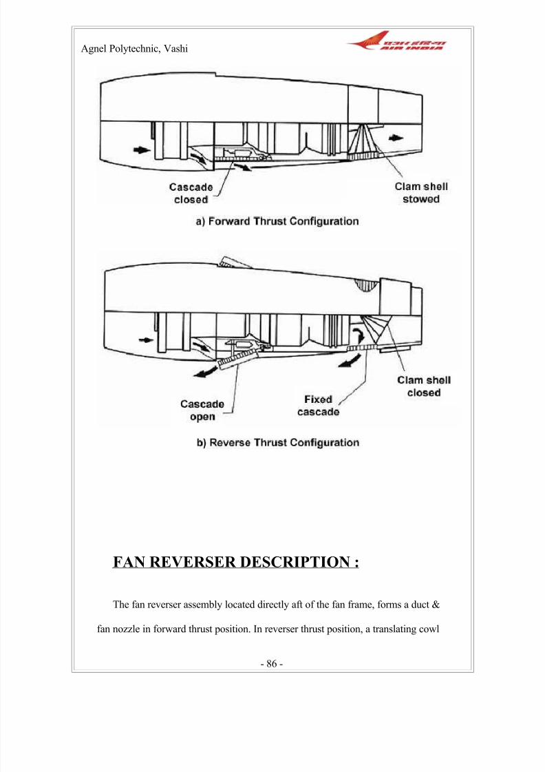
8/2/2019 Henderson Air India Report
http://slidepdf.com/reader/full/henderson-air-india-report 86/101
Agnel Polytechnic, Vashi
FAN REVERSER DESCRIPTION :
The fan reverser assembly located directly aft of the fan frame, forms a duct &
fan nozzle in forward thrust position. In reverser thrust position, a translating cowl
- 86 -

8/2/2019 Henderson Air India Report
http://slidepdf.com/reader/full/henderson-air-india-report 87/101
Agnel Polytechnic, Vashi
moves aft & pulls hinged blocker doors into place to divert fan discharge air
outboard & forward through vaned deflectors that are exposed when the translating
cowl moves aft. The fan reverser assembly has two halves that are hinged to the
pylon at the top, clamped to the fan frame at the forward end, & latched together at
the bottom split line. The translating cowl is moved by pneumatically /
mechanically driven ballscrew actuators.
The fan reverser assembly is composed of a left-hand & right hand fan reverser
assembly. Each fan reverser assembly half assembly is operated by a single
pneumatic motor (Center Drive Unit) that is powered by Aircraft Environmental
Control Systems (ECS) air. The Center Drive Unit (CDU) drives the ball screw
actuators through flexible shafts & gearboxes to translate the translating cowl to the
desired position.
Reverser thrust mode operation is possible at all forward indicated ground
speeds of the aircraft up to maximum emergency 225 KCAS. Normal reverser thrust
- 87 -

8/2/2019 Henderson Air India Report
http://slidepdf.com/reader/full/henderson-air-india-report 88/101
Agnel Polytechnic, Vashi
operation at ground speeds lower than 80 knots is not recommended unless for
emergency operation. The system is not designed for normal reverser thrust
operation in flight but is capable for sustaining an inadvertent deployment without
separation; however, damage may occur for certain flight conditions.
The fan reverser, the fan cowl & core cowl are part of the pylon assembly & are
not removed with the engine. The inlet cowl & core primary exhaust nozzle are
removed on engine change.
FAN REVERSER OPERATION :
- 88 -

8/2/2019 Henderson Air India Report
http://slidepdf.com/reader/full/henderson-air-india-report 89/101
Agnel Polytechnic, Vashi
The fan reverser translating cowl is driven to the deploy or the stow position by
three ball screw actuators on each fan reverser half. The power to drive the actuators
is aircraft ECS bleed air ducted to each of two pneumatic actuator driven motor
(CDUs) located at the center position of each fan reverser half.
The CDUs are interconnected to the end actuator gearboxes through flexible
shafts. The pneumatic supply & the direction of the drive motor rotation is
controlled by dual cockpit commands to the Pressure Regulator & Shut-Off Valve
(PRSOV) & the directional Pilot valve & Pressure switch (DPV). Cockpit indication
of translating cowl position is provided by electrical limit switches that are cam
operated by the pneumatic CDUs. The system also provides for core
cooling air exit temperature indication, system arming indication via the
pressure switch, & de-energizing of the PRSOV solenoid after translation stroke
completion. For PMC applications, throttle feedback units (part of the CDUs)
position the aircraft throttle interlock push-pull cables proportional to the translating
cowl position. For FADEC applications, Rotary Variable Displacements
Transducers (RVDTs) attached to the throttle feedback units (part of the CDUs)
provide an electrical signal proportional to the translating cowl position. In a normal
stow or deploy, the feedback of both fan reverser halves remove a throttle block
permitting full engine RPM following 82% translation to deploy & 92% translation
to stow. In the event of inadvertent development, the push-pull cable or the RVDT
with override the pilot command & drive the power lever to engine idle-speed
position.
- 89 -

8/2/2019 Henderson Air India Report
http://slidepdf.com/reader/full/henderson-air-india-report 90/101
Agnel Polytechnic, Vashi
LINK AND SUPPORT :
The blocker door link is attached at one end to the inner cowl support & at the other
end to the blocker door. The link acts as a radius rod controlling the rotation of the
blocker door into the fan airflow path as the translating cowl is deployed.
TRANSLATING COWL DESCRIPTION :
The translating cowl bondment is constructed of graphite / epoxy with a nomex
core. Fiberglass or graphite is used on the face sheet for acoustically treated flow
surfaces. The structure provides an inner & outer path along with a pocket to
enclose the vaned deflector assembly in the stowed position. The translating cowl is
positioned by three-ball screw actuators with its rod end bearings locked into steel
fittings by removable pins. The translation is guided by Teflon coated tee hinged
rails engaging the lined tee slots of the support assembly. Hinge clevises provide the
forward pivot of the deployment of the blocker doors. In the stowed position, a bulb
seal bolted to the translating cowl at the forward edge of the blocker door. Support
rings provide an aerodynamic seal between he fan flow stream & the deflector vane
cavity, attached to the outlet cowl structure at the leading edge are eight reaction
bumpers, which act to snub the translating cowl. Three lockout plates, one at each
actuator location, including two captive nuts each, are used for deactivation security
of the translating cowl.
- 90 -

8/2/2019 Henderson Air India Report
http://slidepdf.com/reader/full/henderson-air-india-report 91/101
Agnel Polytechnic, Vashi
The translating cowls cover the deflectors when the thrust reverser is stowed.
During thrust reverser operation, the translating move aft exposing the deflectors.
The fan bypass air is blocked by the blocker doors & sent through the defectors to
provide reverse thrust. The translating cowl has three access panels per half for
access to CDU & ball screw actuator installation pins.
- 91 -

8/2/2019 Henderson Air India Report
http://slidepdf.com/reader/full/henderson-air-india-report 92/101
Agnel Polytechnic, Vashi
Composite Material Repair
Section
Structure repair includes this new section. Here repairs are carried out on all structures made
of composite material using fiberglass and other composite material at an elevated
temperature. They also work on various aircraft components. Composite materials are
basically materials made of graphite and are very light in weight
- 92 -

8/2/2019 Henderson Air India Report
http://slidepdf.com/reader/full/henderson-air-india-report 93/101
Agnel Polytechnic, Vashi
Materials used In Hot Bonding
1.) Graphite Fabric (thick)
2.) Graphite Fabric (thin)
3.) Fiber Glass Cloth (thick)
4.) Fiber Glass Cloth (thin)
5.) Stainless Steel Wire Mesh
6.) Perforated Parting Film Fabric
7.) Non Perforated Parting Film
8.) Perforated Skin
9.) Breather Cloth
10.) Bagging Film Vacuum
11.) Perforated Parting Film
- 93 -

8/2/2019 Henderson Air India Report
http://slidepdf.com/reader/full/henderson-air-india-report 94/101
Agnel Polytechnic, Vashi
Composite materials, often shortened to composites, are engineered materials made from
two or more constituent materials with significantly different physical or chemical
properties which remain separate and distinct on a macroscopic level within the finished
structure.
- 94 -

8/2/2019 Henderson Air India Report
http://slidepdf.com/reader/full/henderson-air-india-report 95/101
Agnel Polytechnic, Vashi
RADOME
A radome (the word is a contraction of radar and dome) is a structural, weatherproof
enclosure that protects a microwave or radar antenna. The radome is constructed of material
that minimally attenuates the electromagnetic signal transmitted or received by the antenna.
In other words, the radome is transparent to radar or radio waves. Radomes protect the
antenna surfaces from the environment (e.g., wind, rain, ice, sand, ultraviolet rays, etc.)
and/or conceal antenna electronic equipment from public view. They also protect nearby
personnel from being accidentally struck by quickly-rotating antennas.
Radomes can be constructed in several shapes (spherical, geodesic, planar, etc.) depending
upon the particular application using various construction materials (fiberglass, PTFE-
coated fabric, etc.). When used on UAVs or other aircraft, in addition to such protection, the
radome also streamlines the antenna system, thus reducing drag.
- 95 -

8/2/2019 Henderson Air India Report
http://slidepdf.com/reader/full/henderson-air-india-report 96/101
Agnel Polytechnic, Vashi
A non-rotatable radar antenna installation for aircraft for providing 360° azimuthal
scanning, which includes a generally triangular radome carried by the aircraft, and three
substantially planar radar antennas arranged in a triangular platform within the radome.
360° azimuthal coverage is achieved by the sequential side-to-side scanning of the three
antennas. The platform area of the triangular radome and consequently the drag and weight
penalty of the radome upon the aircraft is substantially less than equivalent radar antenna
installations of circular configuration.
- 96 -

8/2/2019 Henderson Air India Report
http://slidepdf.com/reader/full/henderson-air-india-report 97/101
Agnel Polytechnic, Vashi
RADOME - FACTS
1) The radome is one of the most important parts on the airplane. It must be able to
withstand the abuse of normal flight while providing a window through which the radar
signal can be sent.
2) If you think that your aircraft weather radar is supplying a false or inaccurate signal, the
problem may very well be the radome and not the radar system itself.
3) The term radome comes from radar and dome – a dome shaped structure housing the
radar antenna.
4) Radomes are typically made up using a honeycomb core material with several layers of
fiberglass bonded to the core. A distinct number of coatings are applied in proper order
including an anti static coating to conduct.
5) If the radome has moisture, impact damage, or has been repaired improperly, the radar
signal strength that passes through it will be degraded.
6) Proper maintenance of the radome is critical to achieve maximum signal strength from
the radar transmitter.
7) The most common type of damage will be caused by moisture seeping into the core
material of the radome. This is usually a result of constant hammering from rain over a long
period of time. The moisture collects in the core material and begins a freeze/thaw cycle
each time the airplane is flown. This eventually breaks down the honeycomb material
causing a soft spot on the radome itself. Usually, this can be detected visually and by using
- 97 -

8/2/2019 Henderson Air India Report
http://slidepdf.com/reader/full/henderson-air-india-report 98/101
Agnel Polytechnic, Vashi
a tap test. Sometimes it will result in delamination of fiberglass plies and sometimes
moisture buildup will only be detected using a moisture meter. In either case,
the radar signal is significantly degraded by the presence of moisture. It is very difficult for
a radar signal to penetrate a delaminated area. Damage of this type usually requires
replacement of the damaged core.
8) Screw holes where diverter strips are often attached can also introduce moisture into the
radome.
9) Other types of damage include hail damage, bird strikes, lightning strikes, and other
types of impact damage. These are usually very apparent and require major repair. Often
major damaged radomes require a tool (mold of the original radome) to adequately effect a
repair.
- 98 -

8/2/2019 Henderson Air India Report
http://slidepdf.com/reader/full/henderson-air-india-report 99/101
Agnel Polytechnic, Vashi
Conclusion
In the period of the 22 weeks spent at Air India LTD. I have
gained invaluable theoretical and practical experience in the field of
aviation.
Besides technical knowledge, I learnt the importance of the working
atmosphere, the working culture, teamwork, the structure of the
workforce and other aspects related to the working atmosphere.
It was an absolute pleasure and the most exciting and
informative experience of my engineering course.
To Summarize the benefits gained from the inplant training..
- It helped me understand what goes on in an industry. The workings
of an engineering section.
- Getting to know the different subsections of my allotted section
(C.O.D)
- Learning about the latest advancement in the field of aviation
technology and the latest advancement of the aircrafts in general.
- 99 -

8/2/2019 Henderson Air India Report
http://slidepdf.com/reader/full/henderson-air-india-report 100/101
Agnel Polytechnic, Vashi
- Learnt the work structure and the allotment of rank in a section.
- Got an insight to the psyche of the Workers, Managers, AMEs and
how each of them handle their duties respectively.
- Learning in basic about the concept of flight
- Learning in basic about “How an Aircraft Takes Off and Lands?”
- Got to Learn the engineering jargon used in the aviation department.
This inplant training has greatly increased my interest in the field of
aviation.
Thus I conclude that the training provided to me was very beneficial
and I thank everyone who helped and guided me throughout the 6
month period.
References & Bibliography
- 100 -

8/2/2019 Henderson Air India Report
http://slidepdf.com/reader/full/henderson-air-india-report 101/101
Agnel Polytechnic, Vashi
1. www.Google .com
2. www.Wikipedia .com
3. www.airbus.com
4. www.boeing.com
5. www.goodrich.com
6. www.airliners.net
7. www.airindia.gov.in
8. www.yahoo.com