helicon wave physics impacts on electrodeless thruster design · helicon wave physics impacts on...
TRANSCRIPT
HELICON WAVE PHYSICS IMPACTS ON ELECTRODELESS THRUSTERDESIGN
James GillandOAI
22800 Cedar Point Rd.Brookpark, OH 44142
ABSTRACT
Effective generation of helicon waves for high density plasma sources is determined by the dispersionrelation and plasma power balance. Helicon wave plasma sources inherently require an applied magneticfield of .01-0.1 T, an antenna properly designed to couple to the helicon wave in the plasma, and an rf powersource in the 10-100’s of MHz, depending on propellant choice. For a plasma thruster, particularly one witha high specific impulse (>2000 s), the physics of the discharge would also have to address the use of electroncyclotron resonance (ECR) heating and magnetic expansion. In all cases the system design includes anoptimized magnetic field coil, plasma source chamber, and antenna. A preliminary analysis of such asystem, calling on experimental data where applicable and calculations where required, has been initiated atGlenn Research Center. Analysis results showing the mass scaling of various components as well as thrusterperformance projections and their impact on thruster size are discussed.
INTRODUCTION
Electric propulsion thrusters either currently in use (resistojets, arcjets, pulsed plasma thrusters and ionengines) or near realization (MPD thrusters) share a common requirement for electrodes in direct contactwith the plasma they generate. The interaction of a hot, high speed fluid with metals both imposes thrusteroperating lifetime limits and restricts the propellants that might be used. Of course, other propellantproperties such as atomic mass and ionization energies, which can determine exhaust velocity and efficiency,also affect propellant choice. The elimination of the electrode-plasma interaction could either increaselifetime with high performance propellants, or allow the use of in-situ propellants such as lunar oxygen.While the use of in-situ molecular propellants may result in lower specific impulse or efficiency, the abilityto refuel en route instead of relying on propellants launched from Earth could provide some overall missionbenefit.
The electrodeless generation of plasmas implies time-varying fields to remotely induce currents in a gas.Most simply, an inductive coil can be used to generate a plasma. This technique is used in theRadiofrequency Ion Thruster (RIT) thruster concept, but does not eliminate the need for electrostatic gridsexposed to the plasma1. The inductive method also suffers from its lack of ability to penetrate the plasmabeyond the skin depth2. By applying a magnetic field to the discharge chamber, a host of plasma waves canbe accessed which allow electromagnetic energy to penetrate throughout the plasma and heat it efficiently.One set of plasma waves of interest for electric propulsion is the helicon-electron cyclotron wave. This isthe right-hand polarized wave that propagates parallel to a magnetic field at frequencies above the ioncyclotron (Wci) and below the electron cyclotron (Wce) frequencies (Wci << w <<W ce); in an unboundedplasma the wave is called the whistler wave. In bounded magnetized plasmas, the helicon wave ischaracterized by non-resonant collisional heating of electrons; the cyclotron wave, at w = W ce, resonantlyheats electrons in the plane perpendicular to the applied field. This resonant heating introduces thepossibility of heating electrons above the Maxwellian temperature of the bulk plasma. This nonthermalenergy distribution also has the potential for high Isp operation by expelling these superthermal electrons outof a magnetic nozzle.
Helicon Waves and Sources
Helicon sources have been operated in the laboratory in various gases3, rf powers ranging from 100 W4 -10kWe5 (Hooper), and magnetic fields from 80 to 2000 G. Typical sources consist of a cylindrical dielectricvacuum chamber located coaxially with applied field coils, and with a copper antenna wrapped around the
https://ntrs.nasa.gov/search.jsp?R=20070032051 2018-07-05T05:13:40+00:00Z
2
outside of the dielectric chamber. Gas is introduced into the chamber and a plasma is created by applying100-1000 W of rf power to the antenna. These sources have demonstrated the ability to generate highdensity (ne ~1018-1019 m-3), relatively low temperature (3-5 eV) plasmas. In most of these sources, the aspectratio (length/diameter) was large, and frequencies were much lower than Wce
6,7.
At frequencies below one half of Wce, two possible wave solutions are possible, the helicon/whistler branchand a surface wave branch; at frequencies higher than Wce/2, a single wave solution, the electron cyclotronwave, exists8. The highest densities occur at frequencies well below W ce, often near the lower hybridresonance frequency (
†
wLH ª WceWci )9. In terrestrial helicon sources, aimed primarily at plasma processingapplications, the electron temperatures (Te) are low, on the order of 3-5 eV6. The corresponding iontemperatures are an order of magnitude lower, but might reach 1 eV when operating near the lower hybridfrequency10. Conversion of the isotropic electron temperatures to directed axial motion will only produceexhaust velocities on the order of 10 km/s, which is inadequate for most planetary missions11.
In contrast, ECR heating of plasmas offers the potential for high Te due to the resonant nature of thewave/particle interaction. ECR waves have often been used to heat plasmas for fusion applications12 for thisreason. The physics of the resonance are well known13, but the process results in electrons with increasedkinetic energy in the plane perpendicular to the applied magnetic field. The deposition of energy into theperpendicular motion of the electrons creates a further benefit for propulsion applications. Conservation ofmagnetic moment in an adiabatic plasma allows for a plasma with high perpendicular temperature toaccelerate in the parallel direction along a diverging magnetic field13. The reverse of this behavior is theconfinement of plasmas in magnetic mirrors. This conservation allows an ECR thruster to converttemperature to thrust. Previous research has been done in using purely ECR heating for plasma propulsion;however, penetration of ECR frequencies into a plasma proved to be problematic, limited the density in thedischarge chamber, and resulted in wall damage from backstreaming ions and electrons14.
Whistler Dispersion Relation: The dispersion relation gives the dependence of the helicon wave onmagnetic field strength and plasma density. The well-known cold plasma dispersion tensor is a first step indefining this dependence. In the Stix notation15 this tensor is expressed as
†
S - nz2 - iD nz
2n^2
iD S - n2 0nz
2n^2 0 P - n^
2
È
Î
Í Í Í
˘
˚
˙ ˙ ˙
(1)
Where
†
S =1-w pe
2
w 2 - Wce2 , D = -
w pe2 Wce
w(w 2 - Wce2 )
, P =1-w pe
2
w 2
nz =c kz
w, n^ =
c k^
w
(2)
and wpe =
†
nee2
mee0
is the electron plasma frequency. The above tensor assumes rectangular coordinates, with
the z coordinate defined as the direction parallel to the magnetic field. In the expressions above, ion motionhas been neglected, which implies that w >> wLH >> Wci, which is reasonable for frequencies of interest inthis application. The dispersion relation is found by taking the determinant of the tensor and setting it equalto zero. For a fixed applied wave frequency, the determinant produces a function D(kz, k^, ne, B0) whichdefines the wave propagation as a function of plasma conditions.
In the thruster application considered here, the magnetic field is formed by a solenoidal coil. The fieldexpands outside of the coil and varies in strength and direction. Similarly, the plasma flowing along themagnetic field lines also expands, resulting in a two-dimensional density field. Low fields in the expansionallow w to approach W ce. These conditions differ from most experimental helicon sources, which haveradially and axially uniform magnetic fields and axially uniform density distributions, and run at frequenciesmuch lower than Wce. In these more traditional sources, the dispersion relation is simplified by setting w/wpe
~0 and w/Wce~0. For an ECR thruster, the w/Wce terms must be retained. For an expanding plasma, w/wpe
also cannot be assumed to be zero. All orders of these two ratios were kept in the dispersion relationderivation.
3
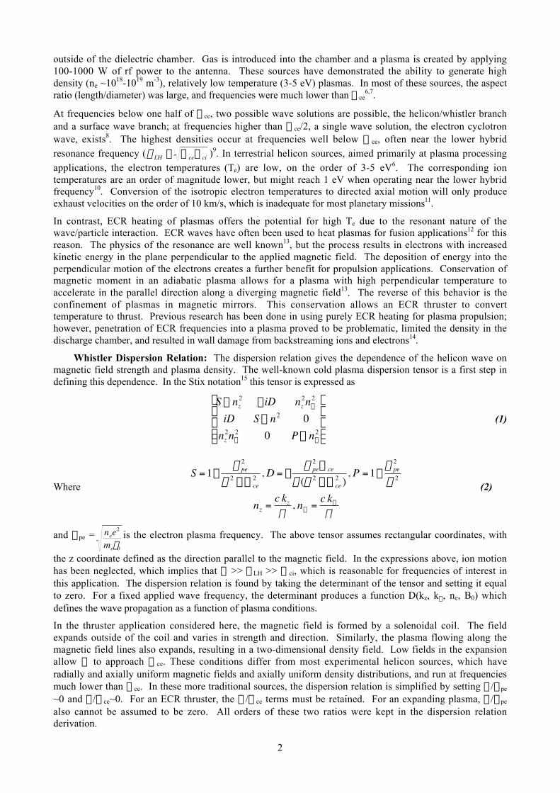
The dispersion relation was calculated in terms of the variables d=w/Wce, kz, k^, and ne. The full solution tothe dispersion relation, solving for kz or for ne, for example, results in 2 real roots corresponding to the twobranches of the helicon wave. The existence of two solutions is shown in Figure 1, which shows ne as afunction of kz for fixed k^ and different values of d. Two representative, albeit not ideal, ECR thrusterconcepts have been considered: a small, narrow source with 2 cm radius, and a larger broad source withradius 10 cm. To calculate the expected density to be achieved in the high field region, the cold plasmadispersion relation was used for wavelengths based on the size of the discharge. In Figure 1, a value of
†
3.83 a was chosen for k^, where 3.83 is a zero of the J0 Bessel equation often seen in calculations of waveradial profiles, and a is the source radius. The existence of two density solutions at low d and density ismore evident in the narrow source example. At fixed density and low d, two possible kz options exist. Thesecorrespond to the helicon wave in the bulk of the plasma, and an edge localized surface wave16. At d ≥ 0.5,only the surface wave can exist, and it is often referred to as the electron cyclotron wave. Propagation in anexpanding magnetic field would follow a path in Figure 1 from high density, low d, low kz to low density,d=1, high kz.
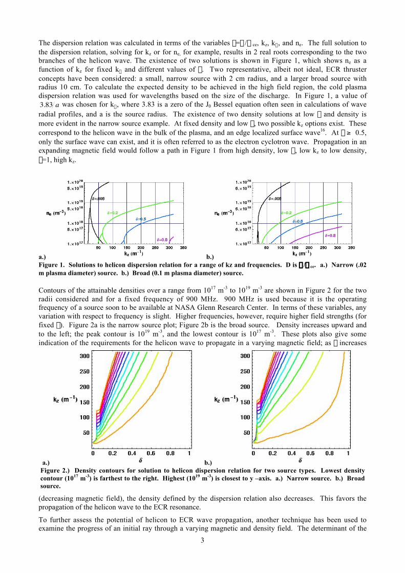
Contours of the attainable densities over a range from 1017 m-3 to 1019 m-3 are shown in Figure 2 for the tworadii considered and for a fixed frequency of 900 MHz. 900 MHz is used because it is the operatingfrequency of a source soon to be available at NASA Glenn Research Center. In terms of these variables, anyvariation with respect to frequency is slight. Higher frequencies, however, require higher field strengths (forfixed d). Figure 2a is the narrow source plot; Figure 2b is the broad source. Density increases upward andto the left; the peak contour is 1019 m-3, and the lowest contour is 1017 m-3. These plots also give someindication of the requirements for the helicon wave to propagate in a varying magnetic field; as d increases
(decreasing magnetic field), the density defined by the dispersion relation also decreases. This favors thepropagation of the helicon wave to the ECR resonance.
To further assess the potential of helicon to ECR wave propagation, another technique has been used toexamine the progress of an initial ray through a varying magnetic and density field. The determinant of the
a.) b.)Figure 1. Solutions to helicon dispersion relation for a range of kz and frequencies. D is w/Wce. a.) Narrow (.02m plasma diameter) source. b.) Broad (0.1 m plasma diameter) source.
a.) b.)Figure 2.) Density contours for solution to helicon dispersion relation for two source types. Lowest densitycontour (1017 m-3) is farthest to the right. Highest (1019 m-3) is closest to y –axis. a.) Narrow source. b.) Broadsource.
4
dispersion relation can be configured to calculate the change of position in physical and k space15. Therelationship gives ray trajectories as coupled differential equations in both physical and k space:
†
dr r dt
= -dD d
r k
dD dw
dr k
dt=
dD dr r dD dw
(3)
In essence, a path is followed through the contour space which matches the physical expansion of field andwave. A full calculation of ray propagation in this manner would include azimuthal modes of the plasmawave; however, by assuming an axisymmetric mode of the wave, the ray paths can be calculated moresimply. As the axisymmetric mode is a candidate for this thruster concept, the simplified calculationsmaintain some relevance to the problem. The integration of these ray tracing equations requires specificationof the applied magnetic field and densities. The calculation of these fields will be briefly described in thesection below.
Helicon/ECR Thruster
To take advantage of both the high density helicon source and the high temperature/exhaust velocity ECRsource requires propagating a helicon wave in a plasma that expands along a diverging magnetic field. Thefrequency used must be lower than the electron cyclotron resonance frequency in the maximum magneticfield region. The helicon wave is launched by an antenna in the high-field region. The high plasma density,low Te plasma in this region is created by the non-resonant absorption of the helicon wave. The field strength
and density decrease as the field expands, and the helicon wave changes wavelength to continue propagatingup to the resonance location, where it is absorbed.
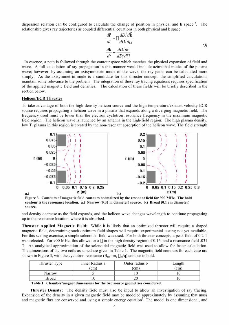
Thruster Applied Magnetic Field: While it is likely that an optimized thruster will require a shapedmagnetic field, determining such optimum field shapes will require experimental testing not yet available.For this scaling exercise, a simple solenoidal field was used. For both thruster concepts, a peak field of 0.2 Twas selected. For 900 MHz, this allows for a d in the high density region of 0.16, and a resonance field .031T. An analytical approximation of the solenoidal magnetic field was used to allow for faster calculation.The dimensions of the two coils assumed are given in Table 1. The magnetic field contours for each case areshown in Figure 3, with the cyclotron resonance (Bres=me wrf/q) contour in bold.
Thruster Type Inner Radius a(cm)
Outer radius b(cm)
Length(cm)
Narrow 5 10 10Broad 10 20 10
Table 1. Chamber/magnet dimensions for the two source geometries considered.
Thruster Density: The density field must also be input to allow an investigation of ray tracing.Expansion of the density in a given magnetic field may be modeled approximately by assuming that massand magnetic flux are conserved and using a simple energy equation2. The model is one dimensional, and
a.) b.)Figure 3. Contours of magnetic field contours normalized by the resonant field for 900 MHz. The boldcontour is the resonance location. a.) Narrow (0.02 m diameter) source. b.) Broad (0.1 cm diameter)source.
5
assumes that the plasma flow is purely axial and that density and velocity are constant across the radius ofthe flow:
†
n uz ⋅ A = n0 uz0 ⋅A0
Bz ⋅ A = Bz0 ⋅ A0
n = n0 e-qf
T
M uz2
2+ qf =
M uz02
2, u0 =
qTe
M
(4)
This simple model breaks down where the field, and therefore the plasma, flows radially. The model can beadapted to allow some radial density variation by defining a radial plasma profile at the source, n0(r). In thispaper a Gaussian profile was assumed:
†
n0(r ,z ) = n0e- r2
w 02 (
B z (0, 0)B z (z, 0) (5)
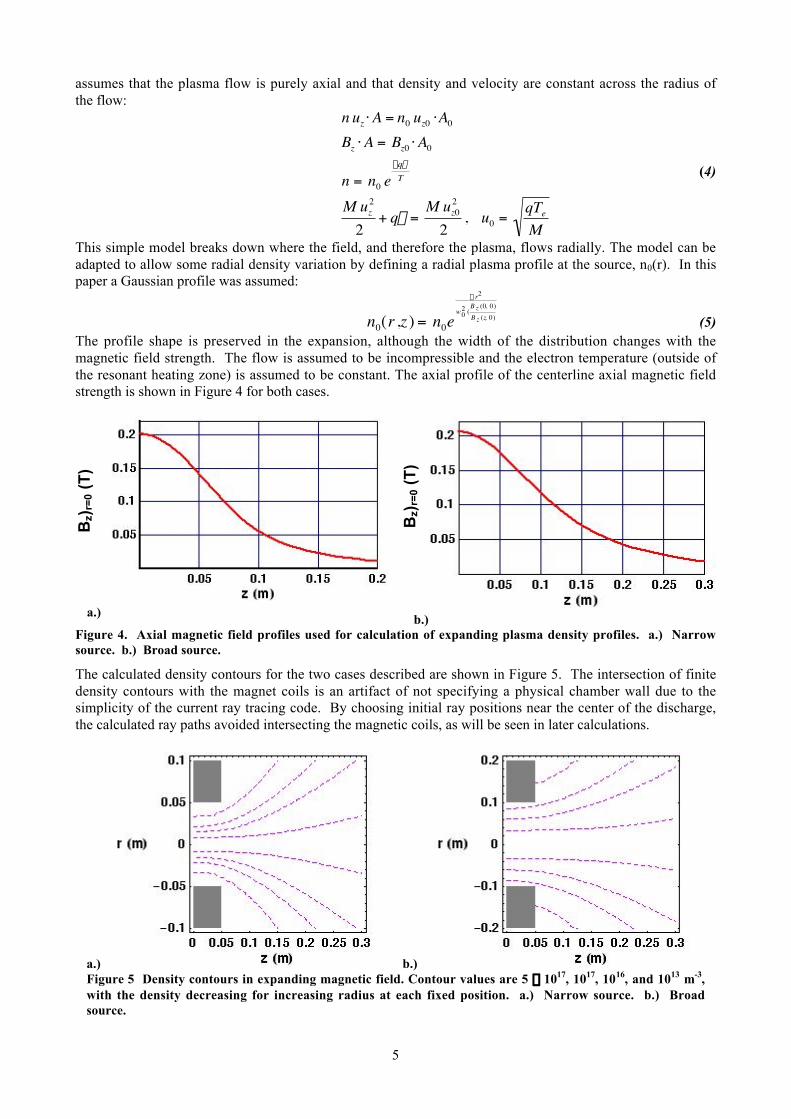
The profile shape is preserved in the expansion, although the width of the distribution changes with themagnetic field strength. The flow is assumed to be incompressible and the electron temperature (outside ofthe resonant heating zone) is assumed to be constant. The axial profile of the centerline axial magnetic fieldstrength is shown in Figure 4 for both cases.
The calculated density contours for the two cases described are shown in Figure 5. The intersection of finitedensity contours with the magnet coils is an artifact of not specifying a physical chamber wall due to thesimplicity of the current ray tracing code. By choosing initial ray positions near the center of the discharge,the calculated ray paths avoided intersecting the magnetic coils, as will be seen in later calculations.
a.) b.)Figure 4. Axial magnetic field profiles used for calculation of expanding plasma density profiles. a.) Narrowsource. b.) Broad source.
a.) b.)Figure 5 Density contours in expanding magnetic field. Contour values are 5 ¥ 1017, 1017, 1016, and 1013 m-3,with the density decreasing for increasing radius at each fixed position. a.) Narrow source. b.) Broadsource.
Bz)
r=0 (
T)
Bz)
r=0 (
T)
6
Helicon wave propagation: With these conditions prescribed, the possibility of helicon wavepropagation to an electron cyclotron resonant surface was investigated using ray tracing. Representativeinitial wave characteristics were chosen based on the basic dispersion relations. Even with the use of thedispersion relation to estimate starting k vectors, a degree of iteration between the dispersion relation (whichassumes uniform plasmas) and the plasma density profile was necessary. The profile effects of the radialdensity distribution meant that the peak density in the Gaussian distribution had to be somewhat higher thanthe calculation for the uniform density case. For both thruster concepts, the uniform density case requireddensities on the order of 5 x 10¹⁷ m-3; the Gaussian distribution required a peak density of 1018 m-3 to allowthe waves to reach the resonance region without diverging into the magnet coil walls.
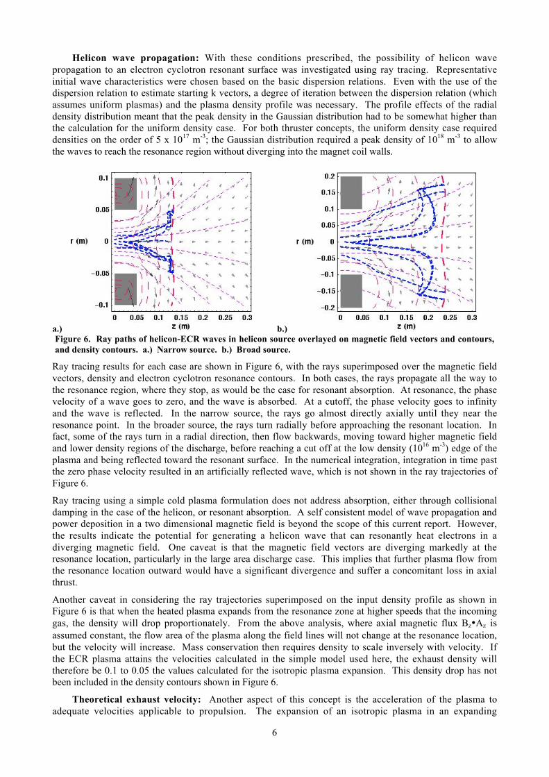
a.) b.)Figure 6. Ray paths of helicon-ECR waves in helicon source overlayed on magnetic field vectors and contours,and density contours. a.) Narrow source. b.) Broad source.
Ray tracing results for each case are shown in Figure 6, with the rays superimposed over the magnetic fieldvectors, density and electron cyclotron resonance contours. In both cases, the rays propagate all the way tothe resonance region, where they stop, as would be the case for resonant absorption. At resonance, the phasevelocity of a wave goes to zero, and the wave is absorbed. At a cutoff, the phase velocity goes to infinityand the wave is reflected. In the narrow source, the rays go almost directly axially until they near theresonance point. In the broader source, the rays turn radially before approaching the resonant location. Infact, some of the rays turn in a radial direction, then flow backwards, moving toward higher magnetic fieldand lower density regions of the discharge, before reaching a cut off at the low density (1016 m-3) edge of theplasma and being reflected toward the resonant surface. In the numerical integration, integration in time pastthe zero phase velocity resulted in an artificially reflected wave, which is not shown in the ray trajectories ofFigure 6.
Ray tracing using a simple cold plasma formulation does not address absorption, either through collisionaldamping in the case of the helicon, or resonant absorption. A self consistent model of wave propagation andpower deposition in a two dimensional magnetic field is beyond the scope of this current report. However,the results indicate the potential for generating a helicon wave that can resonantly heat electrons in adiverging magnetic field. One caveat is that the magnetic field vectors are diverging markedly at theresonance location, particularly in the large area discharge case. This implies that further plasma flow fromthe resonance location outward would have a significant divergence and suffer a concomitant loss in axialthrust.
Another caveat in considering the ray trajectories superimposed on the input density profile as shown inFigure 6 is that when the heated plasma expands from the resonance zone at higher speeds that the incominggas, the density will drop proportionately. From the above analysis, where axial magnetic flux Bz•Az isassumed constant, the flow area of the plasma along the field lines will not change at the resonance location,but the velocity will increase. Mass conservation then requires density to scale inversely with velocity. Ifthe ECR plasma attains the velocities calculated in the simple model used here, the exhaust density willtherefore be 0.1 to 0.05 the values calculated for the isotropic plasma expansion. This density drop has notbeen included in the density contours shown in Figure 6.
Theoretical exhaust velocity: Another aspect of this concept is the acceleration of the plasma toadequate velocities applicable to propulsion. The expansion of an isotropic plasma in an expanding
7
magnetic field was described previously for plasma flow up to the resonant surface. A similar model for aplasma with high perpendicular energy from resonant heating can also be developed. The energyconservation equation is adapted to account for the perpendicular energy term. The expansion of ananisotropic temperature distribution includes an adiabatic invariant, the magnetic moment17,
†
m =qT^
B:
†
n uz ⋅ A = n0 uz0 ⋅A0
Bz ⋅ A = Bz0 ⋅ A0
n = n0 e-qf
T
M uz2
2+ m B + qf =
M uz02
2+ m B0 , u0 =
qTe
M
(6)
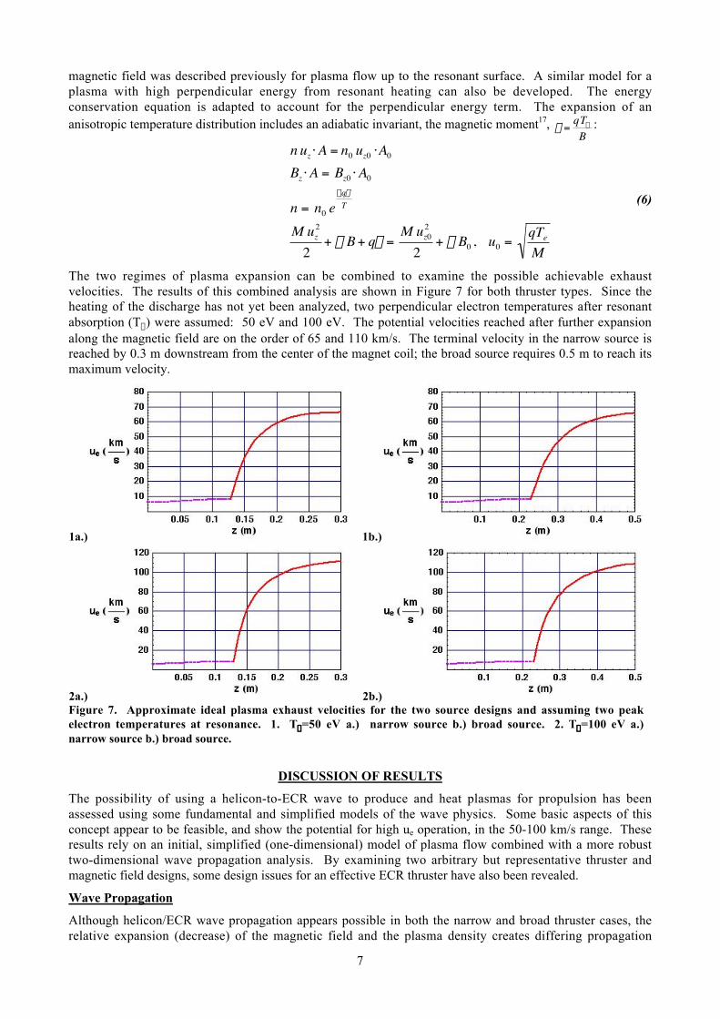
The two regimes of plasma expansion can be combined to examine the possible achievable exhaustvelocities. The results of this combined analysis are shown in Figure 7 for both thruster types. Since theheating of the discharge has not yet been analyzed, two perpendicular electron temperatures after resonantabsorption (T^) were assumed: 50 eV and 100 eV. The potential velocities reached after further expansionalong the magnetic field are on the order of 65 and 110 km/s. The terminal velocity in the narrow source isreached by 0.3 m downstream from the center of the magnet coil; the broad source requires 0.5 m to reach itsmaximum velocity.
1a.) 1b.)
2a.) 2b.)Figure 7. Approximate ideal plasma exhaust velocities for the two source designs and assuming two peakelectron temperatures at resonance. 1. T^=50 eV a.) narrow source b.) broad source. 2. T^=100 eV a.)narrow source b.) broad source.
DISCUSSION OF RESULTS
The possibility of using a helicon-to-ECR wave to produce and heat plasmas for propulsion has beenassessed using some fundamental and simplified models of the wave physics. Some basic aspects of thisconcept appear to be feasible, and show the potential for high ue operation, in the 50-100 km/s range. Theseresults rely on an initial, simplified (one-dimensional) model of plasma flow combined with a more robusttwo-dimensional wave propagation analysis. By examining two arbitrary but representative thruster andmagnetic field designs, some design issues for an effective ECR thruster have also been revealed.
Wave Propagation
Although helicon/ECR wave propagation appears possible in both the narrow and broad thruster cases, therelative expansion (decrease) of the magnetic field and the plasma density creates differing propagation
8
paths. The initial conditions of density and k vector at the middle of the solenoid, are the same for bothcases; however, the broader source has a commensurate wider magnet bore and different field profiles. Inthe case of the narrow source, waves that start in the small bore magnet propagate primarily axially to theresonant point, resulting in energy deposition in a small, relatively high density region of the discharge. Thedensity at the resonance position is from 1 x 10¹⁷ to 5 x 10¹⁷ m-3, and the rays are absorbed in a region whoseradial extent is comparable to the magnet bore radius.
The rays in the broader source diverge more strongly in the radial direction, to the point of reflectingbackward for a period before resuming propagation in the positive axial direction. Helicon waves areinherently parallel waves and must follow the applied field lines. The broad source suffers from greaterradial divergence of the field before the resonant surface, and the ray trajectories indicate this. The rays arenot able to turn axially until the density nears its cut off value, changing the nature of the wave and allowingfor propagation in the positive z direction. In general, the effects of magnetic field are more pronouncedthan the density over most of the plasma for two reasons: 1.) the ratio d (w/Wce) is greater than w/wpe, exceptat the edge. 2.) wpe varies as the square root of density, so that the dependence on density is not as strong asthe dependence on magnetic field. Straighter field lines up to the resonance or lower densities would berequired to have the broad source operate in a manner comparable to the narrow source. One possibilitywould be to have a second trim coil of larger diameter following the first solenoid, to lessen the radial fieldcomponents near the center of the plasma. Further design studies will require more robust computationaltechniques than used in this initial effort.
Thruster PerformanceFor the assumed heating temperatures at the ECR resonance, using the simplified one dimensional expansionanalysis described, both thrusters achieved exhaust velocities of 50-100 km/s for the Te^ values assumed.However, the one dimensional analysis assumes that the magnetic fields are primarily axial, which is notnecessarily true for both source designs. A calculation of the angle of the magnetic field with respect to theaxis at the resonance point for each source shows that for the narrow source, the field is at 30-45° to the axis.For the broad source, the angle at resonance is 80°. The divergence efficiency correction for an angle a is
†
hd =1+ cos(a) 2; the efficiency based on the angle at resonance would be 0.85-0.93 for the narrow source,and 0.59 for the broad source. The effective ue with these numbers drops to 42-93 km/s for the narrowsource, and 29-58 km/s for the broad source. This is still optimistic, because it neglects further divergencealong the field beyond the resonance point.
Thruster Mass and Performance Estimates
Thruster Power: Because of the unknowns in calculating heating, plasma confinement, plasma expansionand plasma detachment downstream of the ECR region, thruster efficiency cannot currently be estimated.Previous estimates of power requirements for these devices using hydrogen propellant gave power levelsfrom 1 to 10 kW, with the lower power levels corresponding to the narrow source and the higher levels to thebroad source. These estimates were based on the ionization power required to maintain the desired plasmadensity at the midpoint of the magnet.
Thruster Mass: Conceptually, an ECR thruster would consist of a dielectric tube 0.04 - 0.1 m in diameter,an antenna made of copper wire or strap, and a 0.2 T magnetic field coil. Of these, the dominant mass is thecoil. An estimate of the coil mass was made based on applied field coil models developed for applied fieldMPD thruster conceptual designs18. The models assumed hyperconducting aluminum coil operating at liquidhydrogen temperatures and regeneratively cooled by the hydrogen propellant. The maximum allowablecurrent was 2000 A. The coil dimensions correspond to the values given in Table 1. The model yields amass of 12.9 kg for the narrow source, and 31.9 kg for the broad source. The power levels assumed werecommensurate with a 20 kW thruster operating at 50 km/s, and the magnets were sized to allow adequatecooling by the propellant flow rate of approximately 10 mg/s. Thruster specific masses would then beapproximately 0.6 kg/kW for the narrow source, and 1.5 kg/kW for the broad source.
FURTHER WORK
Full analysis of a helicon-ECR thruster must take into account multiple, interrelated facets:
1. Wave dispersion in spatially varying magnetic and density fields2. Self consistent wave absorption/plasma heating3. Plasma expansion
9
4. ECR heating including collisional dissipation5. Plasma detachment from expanding magnetic field lines
The models presented herein only take into account the first facet, and partially the third. It is important toremember that the existence of a helicon-wave-generated plasma is assumed in order to provide theconditions for the ray tracing calculations. Coupling between the antenna and plasma, while implied by theinitial dispersion relation calculations, has not been demonstrated to generate the plasma densities assumed.This involves more detailed antenna design as well as experimental verification. Some analysis of the effectsof collisions on the resonantly heated electrons should be possible, and has often been done in regard tofusion applications. However, the self consistent heating and propagation phenomena will probably be bestapproached via experiment. Similarly, the detachment of the plasma from the magnetic field will requireexperiments to fully demonstrate its feasibility.
With these caveats in mind, preliminary analyses show that a helicon-ECR thruster offers the possibility ofelectrodeless, high exhaust velocity electric propulsion. These analyses also indicate some initial designguidelines for effective magnetic field shaping to match the thruster conditions to the desired wavepropagation and absorption. Narrow helicon sources appear to provide more effective plasma utilization andbetter expansion properties for propulsion; a broader source requires magnetic field shaping, possiblythrough the use of a second trim coil, to produce high temperature plasmas in a magnetic field regionsuitable for expansion to high exhaust velocity. Conceptual hydrogen thruster designs with regenerativelycooled hyperconducting magnets show specific mass values of 0.6-1.5 kg/kW at the 20 kW level.
REFERENCES1K. H. Groh and H. W. Loeb, “State of the art radio-frequency ion sources for space propulsion,” Rev. Sci.Instrum. 65 (5), 1994.2M. A. Lieberman and A. J. Lichtenberg, Principles of Plasma Discharges and Materials Processing, Wileyand Sons, NY 1994. p. 429.3A. J. Perry, D. Vender, and R. W. Boswell, “The application of the helicon source to plasma processing,” J.Vac Sci. Technol. B 9 (2), 1991.4 F. F. Chen, “Experiments on helicon plasma sources,” Phys. Plasmas 6 (3), 1999.5B. W. Stallard, E. B. Hooper, and J. L. Power, “Plasma confinement in the whistler wave plasma thruster,”J. Prop. And Power 17 (2): 433-440 MAR-APR 2001.6 J. Gilland, R. Breun, and N. Hershkowitz, “Neutral pumping in a helicon discharge,” Plasma Sources Sci.Technol. 7 (3) 1998.7 P. Zhu, and R. W. Boswell, “ArII Laser Generated by Landau Damping of Whistler Waves at the LowerHybrid Frequency,” Phys. Rev. Lett. 63 (26) 1989.8 Chen, F. F. “Physics of Helicon Discharges,” Phys. Plasmas 3 (5) May 1996.9 Boswell, R. W. “Very efficient plasma generation by whistler waves near the lower hybrid frequency,”Plasma Phys. Controlled Fusion, 26 (10), 1984.10 J. F. Kline, et al., “Slow wave ion heating in the HELIX helicon source,” Plasma Sources Sci. Technol. 11(2002) pp. 413-425.11 J. H. Gilland, “Mission and System Optimization of NEP Vehicles for Lunar and Mars Missions,” IEPCPaper No. 91-038, 1991.12 Y. Tatematsu et al., “Electron cyclotron resonance heating near the turning point in inhomogeneousmagnetic field,” Phys. Plasmas 3 (9), 1996.13 F. Chen, Introduction to Plasma Physics, Plenum Press, New York, 1984.14 J. Sercel, “ECR Thruster Research – Preliminary Theory and Experiments,” AIAA Paper No. 89-2379,July, 1989.15 T. H. Stix, Waves in Plasmas, AIP, NY, NY 1992. pp 7-37.16G. G. Borg and R. W. Boswell, “Power coupling to helicon and Trivelpiece-Gould modes in heliconsources,” Phys. Plasmas. 5 (3) 1998.
10
17 Plasma-flow resulting from electron-cyclotron-resonance heating on a magnetic hill,” Hooper EB Phys.Plasmas 2 (12): 4563-4569 Dec. 1995.18 J. H. Gilland, R. M. Myers, and M. J. Patterson, “Multimegawatt Electric Propulsion System DesignConsiderations,” AIAA Paper No. 90-2552, 1990.