heavy duty dc inverter chiller - orionmachineryna.com · chiller units. individual operation of...
TRANSCRIPT

A Reliable Partner You Can Count On !Inverter chillers are a leading product at ORION and ORION aims to be your best and most reliable partner in the field by making our chillers standard with TESC, making them energy saving, and offering meticulous service.
Built-In TESC Technology!!Built-In TESC Technology!!Triple Eco Speed Control
Achieving "Eco-operation" of minimum required level of
power consumption !
Triple Eco Speed ControlAchieving "Eco-operation" of
minimum required level of power consumption !
2
3
ECO
ECO
ECO
1Refrigerating
machine
Fan
Dischargepump
TESCTriple Eco
Speed Control
Heavy Duty DC Inverter Chiller Catalog
D-RG10EApril 2016
Heavy Duty DC Inverter Chiller
Striving to make products that move you.

Functions and Features
2
The RKE-B Series !!MAX 80%Energy Savings
We've taken inverter compressors which have evolved from AC to DC and fans given them the ability to automatically judge the minimum operating speed required, thus achieving optimized controlled operation. In addition, we've made it easy to set the minimum pump speed. By optimizing these 3 power sources for economical operation, we've brought the ultimate inverter chiller to market!
2
3
ECO
ECO
ECO
1Refrigerating
machine
Fan
Dischargepump
TESCTriple Eco
Speed Control
O.K. up to 50℃
O.K. down to -20℃ (Air cooled model)※When setting antifreeze operating mode.
Summer
Winter
(As an option)
Wide operable ambient temperature (Standard model)
-5℃ 43℃45℃
Wide operable ambient temperature(w/ option for high operable ambient temperature.)
(Conventional model)
50℃-20℃ -15℃expanded
+7℃expanded
3℃5℃
Wide operable fluid temperature
Wide operable fluid temperature (w/ clean water)
(w/ antifreezing fluid.)
(Conventional model)
0℃ 35℃-2℃expanded
-5℃expanded
O.K. down to 0℃Operable fluid temperature range
(When using antifreeze.)
EnergySavings
Point
EnergySavings
Point
EnergySavings
Point
OUTSTA
NDING
MAX60%EnergySavings
RKE7500B-VRKE7500A-V
RKE7500B-V
Noinverterchiller
MAX80%EnergySavings
00 10
10
20
20
30
30
40
40
50
50
60
60
70
70
80
80
90
90
100
100
Load ratio(%)
MAX60%MAX60% New model
(RKE-B)
Conventional model(RKE-A) Inverter control
General constant speed chiller
MAX80%MAX80%
Con
sum
ed p
ower
ratio
(%)
Our uni ts can mainta in control at low loads that were previously difficult to work with and, as the graph shows, even compared with previous inverter driven chillers, we've achieved up to 60% in energy savings!
Can withstand summer temperatures up to 50 ℃ with our special-spec. Our chillers can also exhibit maximum performance in factory environments where hot air flow tends to accumulate. In winter temperatures as low as
-20℃ , you can count on our air cooled models continuing to perform, even in outside installations.
OUTSTANDING ORION CHILLER
Built-In TESC Technology
Wide operable fluid temperature
O.K. up to 50℃
O.K. down to -20℃ (Air cooled model)※When setting antifreeze operating mode.
Summer
Winter
(As an option)
Wide operable ambient temperature (Standard model)
-5℃ 43℃45℃
Wide operable ambient temperature(w/ option for high operable ambient temperature.)
(Conventional model)
50℃-20℃ -15℃expanded
+7℃expanded
3℃5℃
Wide operable fluid temperature
Wide operable fluid temperature (w/ clean water)
(w/ antifreezing fluid.)
(Conventional model)
0℃ 35℃-2℃expanded
-5℃expanded
O.K. down to 0℃Operable fluid temperature range
(When using antifreeze.)
EnergySavings
Point
EnergySavings
Point
EnergySavings
Point
OUTST
ANDING

1 2 3
3
The RKE-B Series !!ORION Offers Energy Savings Specs. Top Class in the Industry !
Wide operable fluid temperatureOperable fluid temperature range : 3℃ - 35℃Low fluid temperature expanded to 3℃
TESC(Three Eco Speed Control)
Triple Optimization
(ECO Speed Control)
PumpSpeed Control
FanSpeed Control
CompressorSpeed
Control O p e r a t e s a t t h e Minimum Speed to
Achieve the Required Flow Rate. Reduced
Wasted Water Supply.
Automatic Optimized Operation Judgment
from the Inverter
DC Inverter Drive w i t h A u t o m a t i c
Optimized Operation Judgment
ORION's newly developed DC Inverter Driver and Special Control Panel offer uniquely optimized control of the refrigeration cycle. Energy Savings as high as 80%.
O.K. up to 50℃
O.K. down to -20℃ (Air cooled model)※When setting antifreeze operating mode.
Summer
Winter
(As an option)
Wide operable ambient temperature (Standard model)
-5℃ 43℃45℃
Wide operable ambient temperature(w/ option for high operable ambient temperature.)
(Conventional model)
50℃-20℃ -15℃expanded
+7℃expanded
3℃5℃
Wide operable fluid temperature
Wide operable fluid temperature (w/ clean water)
(w/ antifreezing fluid.)
(Conventional model)
0℃ 35℃-2℃expanded
-5℃expanded
O.K. down to 0℃Operable fluid temperature range
(When using antifreeze.)
EnergySavings
Point
EnergySavings
Point
EnergySavings
Point
OUTST
ANDING
EnergySavings
Point
EnergySavings
Point
EnergySavings
Point
OUTST
ANDING
Pump Also changed to Inverter DriveEnergy saved by from the refrigeration circuit, but also by use of a water-flow circuit.
Bypass valve
Bypass valve
100% full power operationat all times
Chilledwater
Chilledwater
Water tank
P
Water tank
Bypass valve
Bypass valve
100% full power operationat all times
Chilledwater
Chilledwater
Water tank
P
Water tank
※ Can operate at temps down to 0℃ when using antifreeze.
Unneeded chi l led water simply sent by a bypass valve to a tank.
Even without adjusting the bypass valve, the inverter wil l control the f low to just the required rate in order to avoid waste, and the pressure can be set according to the usage requirements.
●RKE-B Series● Previous models

Functions and Features
4
EnergySavings
Point
EnergySavings
Point
EnergySavings
Point
OUTST
ANDING
EnergySavings
Point
EnergySavings
Point
EnergySavings
Point
OUTST
ANDING
Choice of Pump Control MethodBy adjusting the speed setting of the discharge pump, either the flow rate can be set match a standard flow rate guideline, or the pressure of the discharge pump can be set. It is possible to set the optimum flow rate based on the load or set the pressure.
Operation Control Buttons
Select Discharge Pump Control Method
Change Settings
The operating conditions will be
displayed.
Intelligent Touch PanelVarious settings and operating conditions can be visually and intuitively checked and operated via the touch panel controller.The displayed language can be changed to English, Japanese or Chinese.
Unit operating ratio (Power indicator)
Graph display
Measured PressureTimer Setting
Displayed language can be changed to English, Japanese or Chinese.
Menu
1
2
3
4
5
The compressor operating state is indicated on a 10 level bar graph which shows the level of energy saving at a glance.Touching the "Op. rate" button brings up the Monitor Screen where operating conditions can be easily checked.
Touching the "Measured Fluid Temp." button will change the display to the Graph Screen where changes in fluid temperature will be graphed over a particular time period (up to 53 hours) in order to better aid in fluid temperature management.
Touching "Measured Pressure" brings up a screen where the flow rate setting can easily be changed.※ The flow rate is calculated from the chilled water outlet pressure and characteristics of the pump and should be used for reference only.Touching "0 : 00" on the display allows stop and start times to
be set. Actions can be repeated or set according to the day.
Touching "Menu" will bring up a menu of useful functions for easy confirmation and setting of Parameters, Alarm History, Main Components, Accumulated Time, Timer Function, etc.
Easy Maintenance/Alarm Display6Alarm numbers are displayed when alarm conditions occur.Touching the "Details" button will bring up further details about the alarm and information on what measures to take.
English language mode Chinese language modeJapanese language mode
* The displayed flow rate is a calculated value and may differ from the actual flow rate.

5
Many Useful Functions AvailableEnergySavings
Point
EnergySavings
Point
EnergySavings
Point
OUTST
ANDING
Temperature Accuracy: ± 0.1 ℃
Low Noise and Noise Reducing Design
Operation and Monitoring Via PC or Sequencer Possible
Meets Demands of World Markets
Area ratio - 27%Volume ratio - 31%
Our inverter controlled compressor responds to fluctuating workloads linearly, achieving highly accurate control while using the least amount of energy. Adaptable to various applications that require high accuracy operation by using high level temperature management.
Communications functions can be utilized through a control program to match your specific application.
【Communications】USB: 1unit, RS-422A: 32units, RS-485: 32units
Built to provide reliable service even when exposed to direct rainfall in outdoor installations.※ Installation in direct sunlight, strong wind (8m/sec or higher) contact
with falling snow, or freezing conditions requires further measures.An IPX4 rating refers to the amount and nature of water exposure equipment can withstand. Specifically, it indicates that "equipment can safely withstand contact with rain or water splash from any direction at a rate up to around 10L/min.
We succeeded at integrating the sys tem through the adoption of an immersion pump, and by optimizing the layout of the tank, pump, and heat exchanger. The result was a great reduction in space.
Connect up to 32 Units.
Operations Available Via PC
Starting and stopping of individual chiller units.Individual operation of chiller discharge pumps.Fluid temp. control of individual chillers.
Ask our sales staff for further details.
Requires optional-spec. order. Please consult our sales staff regarding all of your particular needs.
Ideal inverter fan speed control through optimized refrigeration cycle control. Achieves much lower operating noise levels.※ Operating noise measured from a distance of 1m
from the front of the unit at a height of 1m. Library Quiet Park NormalConversation
Busy Office InsideSubway Car
RKE3750B-VRKE5500B-VW
RKE3750B-VW
RKE5500B-V
RKE7500B-VRKE7500B-VW
RKE11000B-VW
SHIII ♪
SHIII ♪
SHIII ♪
OperatingNoise
60dB or less
OperatingNoise
60dB or less
OperatingNoise
60dB or less
OperatingNoise
59dB or less
Space Saving Protective Enclosure for Outdoor Installations (IPX4 equiv.)
CE Marking RoHSOther International Standards
Compared with RKE7500B-V and RKE7500A-V models.
OperatingNoise
63dB or less
Detailed display functions help to get you back up and running immediately.
・ Inspection Warnings ・ Fluid Temp. Warnings・ Water Pressure ・ Refrigeration Circuit ・ Inverter, Etc.

What ORION Can Do For You !
6
EnergySavings
Point
EnergySavings
Point
EnergySavings
Point
OUTST
ANDING
ORION Inverter Chiller Selection Guide
Intelligent touch panel functionality included as standard equipment.Standard functions include calendar and timer functions.
The unit includes a leakage breaker as standard equipment as a preventive measure in order to help ensure safety.
RKE3750B-V(W)-G2 models include casters as standard equipment. Casters are sold as option equipment for RKE5500B-V(W) and RKE7500B-V(W) models.
▼ Set Start/Stop times freely from the timer settings screen. ▼ Menu Screen
▼ Panel Display (Sample English display shown)
We have the equipment that meets your needs !
Intelligent Touch Panel
Earth Leakage Breaker (ELB) Casters
Expanded Fluid Temp. Operating RangeFluid temperature upper/lower limit warning.Now can operate at temps. as low as 0 ℃ when using antifreeze.A warning message can be displayed or an audible alarm
sounded when the fluid temperature goes beyond a set upper or lower limit beyond the set temperature.
Standard Equipment Models
Fluid Temp. Setting(℃)
Fluid Temp. Setting(℃)
HIGH(℃)
LOW(℃)
Can set upper andlower temp. range.
Notice whenupper limitexceeded.
Notice whenlower limitexceeded.
Also meets many other
needs!
* Standard equipment will vary based on particular models. Please consult our sales staff for details.
* See pages 8 to 11 for details.
Tank
Max 40% concentrated solution of ethylene glycol.
※ Max 40% concentrated solution of ethylene glycol.
☆ Note that there will be a 20% reduction in cooling capacity when operating with a 40% concentrated solution of industrial use ethylene glycol.
7
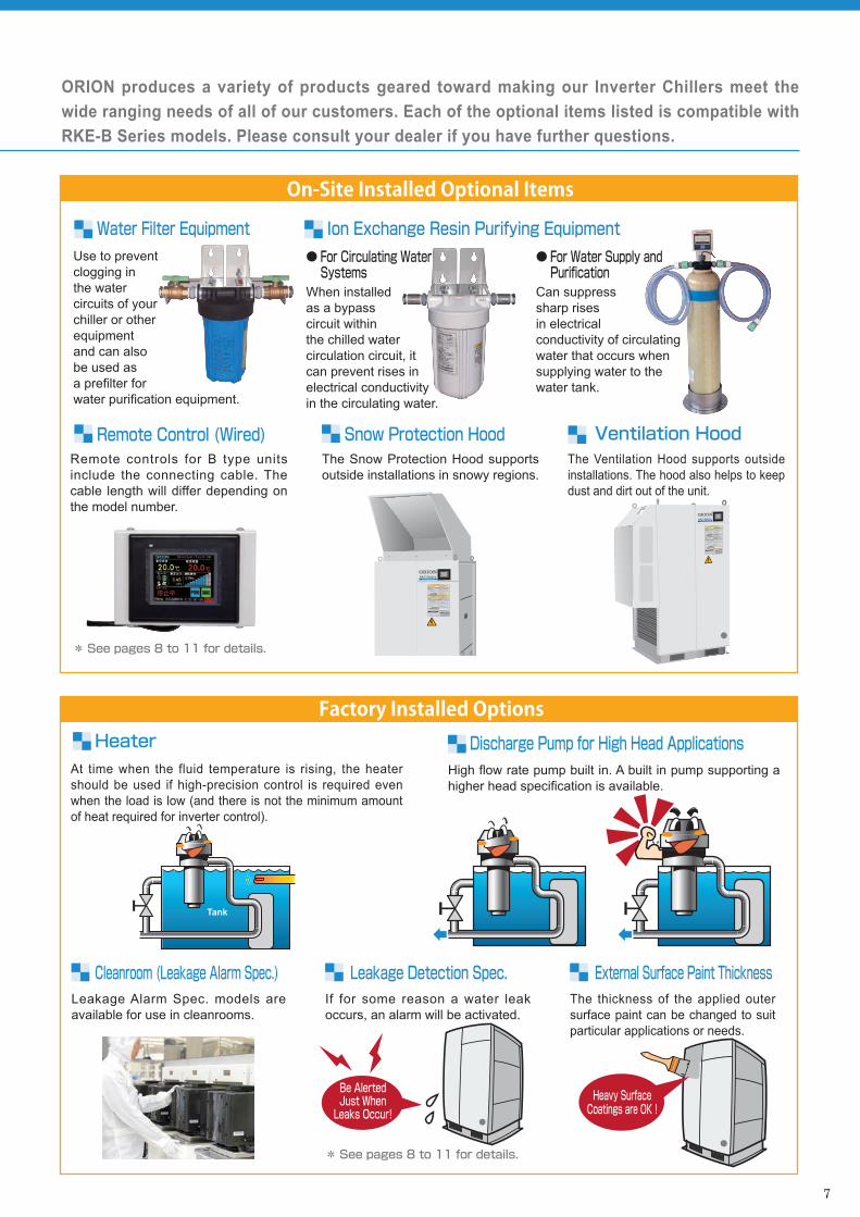
High flow rate pump built in. A built in pump supporting a higher head specification is available.
At time when the fluid temperature is rising, the heater should be used if high-precision control is required even when the load is low (and there is not the minimum amount of heat required for inverter control).
Leakage Alarm Spec. models are available for use in cleanrooms.
The Snow Protection Hood supports outside installations in snowy regions.
If for some reason a water leak occurs, an alarm will be activated.
The thickness of the applied outer surface paint can be changed to suit particular applications or needs.
The Ventilation Hood supports outside installations. The hood also helps to keep dust and dirt out of the unit.
Remote controls for B type units include the connecting cable. The cable length will differ depending on the model number.
● For Circulating Water Systems
When installed as a bypass circuit within the chilled water circulation circuit, it can prevent rises in electrical conductivity in the circulating water.
Be AlertedJust When
Leaks Occur!
Heavy SurfaceCoatings are OK !
Be AlertedJust When
Leaks Occur!
Heavy SurfaceCoatings are OK !
Tank
We have the equipment that meets your needs ! ORION produces a variety of products geared toward making our Inverter Chillers meet the wide ranging needs of all of our customers. Each of the optional items listed is compatible with RKE-B Series models. Please consult your dealer if you have further questions.
Discharge Pump for High Head ApplicationsHeater
Cleanroom (Leakage Alarm Spec.)
Snow Protection Hood
Leakage Detection Spec. External Surface Paint Thickness
Ventilation HoodRemote Control (Wired)
Water Filter Equipment Ion Exchange Resin Purifying Equipment
On-Site Installed Optional Items
Factory Installed Options
● For Water Supply and Purification
Can suppress sharp rises in electrical conductivity of circulating water that occurs when supplying water to the water tank.
* See pages 8 to 11 for details.
* See pages 8 to 11 for details.
Use to prevent clogging in the water circuits of your chiller or other equipment and can also be used as a prefilter for water purification equipment.

EnergySavings
Point
EnergySavings
Point
EnergySavings
Point
OUTST
ANDING
8
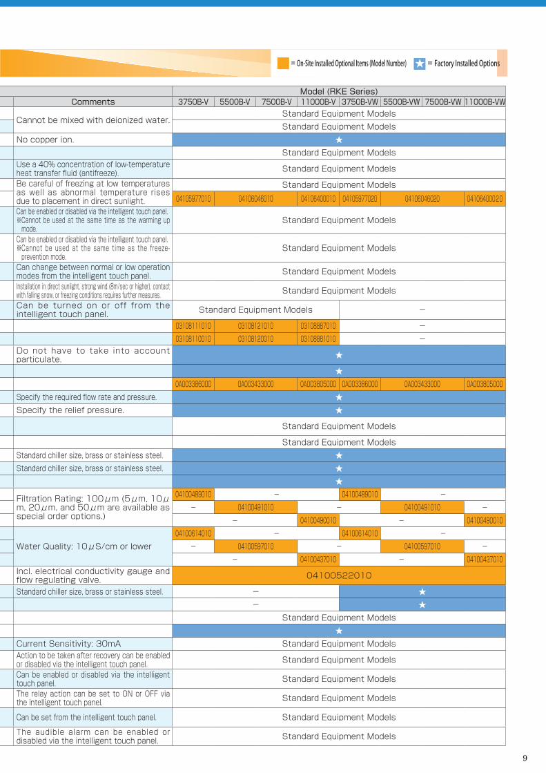
Function Model (RKE Series)Item Detail Comments 3750B-V 5500B-V 7500B-V 11000B-V 3750B-VW 5500B-VW 7500B-VW 11000B-VW
Operating Environm
ent
Low Temperature Heat Transfer Fluid / Nybrine (Z-1) 40% Concentration or LowerCannot be mixed with deionized water.
Standard Equipment ModelsMax 40% concentrated solution of ethylene glycol. Standard Equipment ModelsDeionized (R.O. treated) water. Electrical Conductivity: 1μS/cm or higher. No copper ion. ★
Working Fluid (chilled water) Temperature
3~35℃ Standard Equipment Models
0~35℃ Use a 40% concentration of low-temperature heat transfer fluid (antifreeze). Standard Equipment Models
Ambient TemperatureLow temp. area spec.: -20℃ to 45℃ (air cooled), 2℃ to 45℃ (water cooled) Be careful of freezing at low temperatures
as well as abnormal temperature rises due to placement in direct sunlight.
Standard Equipment ModelsHigh temp. area spec.: to 50℃ 04105977010 04106046010 04106400010 04105977020 04106046020 04106400020
Freeze-Prevention ModeThis function operates the discharge pump in order to prevent water temperature drops and freezing during winter months when unit operations is stopped.When enabled, the discharge pump will operate when the water temperature falls to 3℃ or below.
Can be enabled or disabled via the intelligent touch panel.※ Cannot be used at the same time as the warming up
mode.Standard Equipment Models
Warm Up ModeThis function will automatically operate the discharge pump when the unit is otherwise not operating when the ambient temperature is low, for example during winter months, in order to prevent the water temperature from dropping too much and in order to help maintain the set water temperature. When this mode is enabled, the water temperature can be set within the temperature range of 10℃ to 35℃ as desired.
Can be enabled or disabled via the intelligent touch panel.※ Cannot be used at the same time as the freeze-
prevention mode.Standard Equipment Models
Low Noise Mode This function will limit the upper speed of the fan and the fan ventilation noise level will be decreased.
Can change between normal or low operation modes from the intelligent touch panel. Standard Equipment Models
Outside Installation IPX4 Equiv. Rating Installation in direct sunlight, strong wind (8m/sec or higher), contact with falling snow, or freezing conditions requires further measures. Standard Equipment Models
Snow Protection Mode When enabled, and when the unit is stopped, the fan will periodically and automatically start in order to blow fallen snow from the upper exhaust port.
Can be turned on or off from the intelligent touch panel. Standard Equipment Models -
Snow Protection Hood Prevents falling snow from entering the fan intake. 03108111010 03108121010 03108887010 -Ventilation Hood Consider a wind speed of 8 m/s or higher as a guideline. 03108110010 03108120010 03108881010 -
Cleanroom (Leakage Alarm Spec.) In addition to the standard specification, leakage sensors, pressure resistant piping, refrigerant piping insulation, and water piping insulation are added.
Do not have to take into account particulate. ★
Water Leakage Detection Leak detector built in. ★Vibration Reducing Base Reduces transmission of vibration from the chiller. 0A003386000 0A003433000 0A003805000 0A003386000 0A003433000 0A003805000
Chilled W
ater Circuit
Discharge Pump Specs. High flow rate pump built in. Can replace the built in high pressure pump. Specify the required flow rate and pressure. ★Relief Valve (Pressure valve) Can provide equipment-side pressure protection. Specify the relief pressure. ★Water Tank Water-Level Alarm (Lower limit alarm) Used to avoid water shortages due to evaporation. Standard Equipment Models
Water Supply Port Open/Close
A ball tap is provided in the water tank in order to maintain a uniform water level. Standard Equipment ModelsA ball valve is added to the water supply port. Standard chiller size, brass or stainless steel. ★
Chilled Water Inlet/Outlet Open/Close
Gate valves are added to the chilled water inlet and outlet ports. Standard chiller size, brass or stainless steel. ★Compression fittings are added to the chilled water inlet and outlet ports. ★
Chilled Water Circuit Water Filter
Water Filter "A" Assembly Filtration Rating: 100μm (5μm, 10μm, 20μm, and 50μm are available as special order options.)
04100489010 ― 04100489010 ―Water Filter "B" Assembly ― 04100491010 ― 04100491010 ―Water Filter "C" Assembly ― 04100490010 ― 04100490010
Deionized Water Equipment for Chilled Water Circulation Circuit
Water Purifier "C" AssemblyWater Quality: 10μS/cm or lower
04100614010 ― 04100614010 ―Water Purifier "D" Assembly ― 04100597010 ― 04100597010 ―Water Purifier "E" Assembly ― 04100437010 ― 04100437010
Deionized Water Equipment for Chilled Water Supply and Supply Circuits Purification assembly for supply water. Incl. electrical conductivity gauge and
flow regulating valve. 04100522010
Cooling Water (Condenser circuit) Inlet/Outlet Open/Close
Gate valves are added to the cooling water inlet and outlet ports. Standard chiller size, brass or stainless steel. - ★Compression fittings are added to the cooling water inlet and outlet ports. - ★
Power Supply and Control Specs
Primary Power Supply Voltage
Three-phase 200V (50/60Hz), Three-phase 220V (60Hz) Standard Equipment ModelsThree-phase 230V (50Hz), 380V・400V・415V・440V・480V (50/60Hz) ★
Overload Safety Devices The unit comes with a built in multipurpose overload and short circuit protection breaker. Current Sensitivity: 30mA Standard Equipment ModelsPower Outage Recovery Operation Settings
Can choose the recovery pattern after power outage. (Manual recovery•Automatic recovery•Remote operation priority)
Action to be taken after recovery can be enabled or disabled via the intelligent touch panel. Standard Equipment Models
Operation Action Settings Can enable or disable operation from among the main unit, remote control, external communications, or remote switch.
Can be enabled or disabled via the intelligent touch panel. Standard Equipment Models
Alarm Signal Output Options
Can choose the state of contacts of the remote alarm signal output. (Contacts either ON or OFF during alarm condition.)
The relay action can be set to ON or OFF via the intelligent touch panel. Standard Equipment Models
Action on Compressor Related Alarm
In cases where an alarm signal has been generated, this setting allows the user to choose whether the unit will completely shut down or if components that are able to operate will continue to do so. Can be set from the intelligent touch panel. Standard Equipment Models
Audible Alarm Enable/Disable Audible alarm can be enabled or disabled for each audible alarm or warning. The audible alarm can be enabled or
disabled via the intelligent touch panel. Standard Equipment Models
What ORION Can Do For You !
ORION Inverter Chiller Equipment List
9
Function Model (RKE Series)Item Detail Comments 3750B-V 5500B-V 7500B-V 11000B-V 3750B-VW 5500B-VW 7500B-VW 11000B-VW
Operating Environm
ent
Low Temperature Heat Transfer Fluid / Nybrine (Z-1) 40% Concentration or LowerCannot be mixed with deionized water.
Standard Equipment ModelsMax 40% concentrated solution of ethylene glycol. Standard Equipment ModelsDeionized (R.O. treated) water. Electrical Conductivity: 1μS/cm or higher. No copper ion. ★
Working Fluid (chilled water) Temperature
3~35℃ Standard Equipment Models
0~35℃ Use a 40% concentration of low-temperature heat transfer fluid (antifreeze). Standard Equipment Models
Ambient TemperatureLow temp. area spec.: -20℃ to 45℃ (air cooled), 2℃ to 45℃ (water cooled) Be careful of freezing at low temperatures
as well as abnormal temperature rises due to placement in direct sunlight.
Standard Equipment ModelsHigh temp. area spec.: to 50℃ 04105977010 04106046010 04106400010 04105977020 04106046020 04106400020
Freeze-Prevention ModeThis function operates the discharge pump in order to prevent water temperature drops and freezing during winter months when unit operations is stopped.When enabled, the discharge pump will operate when the water temperature falls to 3℃ or below.
Can be enabled or disabled via the intelligent touch panel.※ Cannot be used at the same time as the warming up
mode.Standard Equipment Models
Warm Up ModeThis function will automatically operate the discharge pump when the unit is otherwise not operating when the ambient temperature is low, for example during winter months, in order to prevent the water temperature from dropping too much and in order to help maintain the set water temperature. When this mode is enabled, the water temperature can be set within the temperature range of 10℃ to 35℃ as desired.
Can be enabled or disabled via the intelligent touch panel.※ Cannot be used at the same time as the freeze-
prevention mode.Standard Equipment Models
Low Noise Mode This function will limit the upper speed of the fan and the fan ventilation noise level will be decreased.
Can change between normal or low operation modes from the intelligent touch panel. Standard Equipment Models
Outside Installation IPX4 Equiv. Rating Installation in direct sunlight, strong wind (8m/sec or higher), contact with falling snow, or freezing conditions requires further measures. Standard Equipment Models
Snow Protection Mode When enabled, and when the unit is stopped, the fan will periodically and automatically start in order to blow fallen snow from the upper exhaust port.
Can be turned on or off from the intelligent touch panel. Standard Equipment Models -
Snow Protection Hood Prevents falling snow from entering the fan intake. 03108111010 03108121010 03108887010 -Ventilation Hood Consider a wind speed of 8 m/s or higher as a guideline. 03108110010 03108120010 03108881010 -
Cleanroom (Leakage Alarm Spec.) In addition to the standard specification, leakage sensors, pressure resistant piping, refrigerant piping insulation, and water piping insulation are added.
Do not have to take into account particulate. ★
Water Leakage Detection Leak detector built in. ★Vibration Reducing Base Reduces transmission of vibration from the chiller. 0A003386000 0A003433000 0A003805000 0A003386000 0A003433000 0A003805000
Chilled W
ater Circuit
Discharge Pump Specs. High flow rate pump built in. Can replace the built in high pressure pump. Specify the required flow rate and pressure. ★Relief Valve (Pressure valve) Can provide equipment-side pressure protection. Specify the relief pressure. ★Water Tank Water-Level Alarm (Lower limit alarm) Used to avoid water shortages due to evaporation. Standard Equipment Models
Water Supply Port Open/Close
A ball tap is provided in the water tank in order to maintain a uniform water level. Standard Equipment ModelsA ball valve is added to the water supply port. Standard chiller size, brass or stainless steel. ★
Chilled Water Inlet/Outlet Open/Close
Gate valves are added to the chilled water inlet and outlet ports. Standard chiller size, brass or stainless steel. ★Compression fittings are added to the chilled water inlet and outlet ports. ★
Chilled Water Circuit Water Filter
Water Filter "A" Assembly Filtration Rating: 100μm (5μm, 10μm, 20μm, and 50μm are available as special order options.)
04100489010 ― 04100489010 ―Water Filter "B" Assembly ― 04100491010 ― 04100491010 ―Water Filter "C" Assembly ― 04100490010 ― 04100490010
Deionized Water Equipment for Chilled Water Circulation Circuit
Water Purifier "C" AssemblyWater Quality: 10μS/cm or lower
04100614010 ― 04100614010 ―Water Purifier "D" Assembly ― 04100597010 ― 04100597010 ―Water Purifier "E" Assembly ― 04100437010 ― 04100437010
Deionized Water Equipment for Chilled Water Supply and Supply Circuits Purification assembly for supply water. Incl. electrical conductivity gauge and
flow regulating valve. 04100522010
Cooling Water (Condenser circuit) Inlet/Outlet Open/Close
Gate valves are added to the cooling water inlet and outlet ports. Standard chiller size, brass or stainless steel. - ★Compression fittings are added to the cooling water inlet and outlet ports. - ★
Power Supply and Control Specs
Primary Power Supply Voltage
Three-phase 200V (50/60Hz), Three-phase 220V (60Hz) Standard Equipment ModelsThree-phase 230V (50Hz), 380V・400V・415V・440V・480V (50/60Hz) ★
Overload Safety Devices The unit comes with a built in multipurpose overload and short circuit protection breaker. Current Sensitivity: 30mA Standard Equipment ModelsPower Outage Recovery Operation Settings
Can choose the recovery pattern after power outage. (Manual recovery•Automatic recovery•Remote operation priority)
Action to be taken after recovery can be enabled or disabled via the intelligent touch panel. Standard Equipment Models
Operation Action Settings Can enable or disable operation from among the main unit, remote control, external communications, or remote switch.
Can be enabled or disabled via the intelligent touch panel. Standard Equipment Models
Alarm Signal Output Options
Can choose the state of contacts of the remote alarm signal output. (Contacts either ON or OFF during alarm condition.)
The relay action can be set to ON or OFF via the intelligent touch panel. Standard Equipment Models
Action on Compressor Related Alarm
In cases where an alarm signal has been generated, this setting allows the user to choose whether the unit will completely shut down or if components that are able to operate will continue to do so. Can be set from the intelligent touch panel. Standard Equipment Models
Audible Alarm Enable/Disable Audible alarm can be enabled or disabled for each audible alarm or warning. The audible alarm can be enabled or
disabled via the intelligent touch panel. Standard Equipment Models
ORION Inverter Chiller Equipment List = On-Site Installed Optional Items (Model Number) ★ = Factory Installed Options

10
Function Model (RKE Series)Item Detail Comments 3750B-V 5500B-V 7500B-V 11000B-V 3750B-VW 5500B-VW 7500B-VW 11000B-VW
Pow
er Supply and C
ontrol Specs
Independent Pump Operation / Control Setting
Pump-only operation can be enabled/disabled via the main unit, remote control, external communications signal, or the remote switch.
Can be enabled or disabled via the intelligent touch panel. Standard Equipment Models
Settings Lock Setting Control from each of the following can be enabled or disabled: Main Unit, Remote Control, or External Communications Signal.
Can be enabled or disabled via the intelligent touch panel. Standard Equipment Models
Fluid (Chilled Water) Temp. Upper/Lower Limit Warning Option
The method of abnormal fluid (chilled water) temperature detection can be selected. Can enable or disable the alarm and standby sequence for relative value and absolute value alarms.※Regarding the standby sequence, the alarm will be output after startup until the fluid temperature has initially reached a normal value and then later goes outside the normal range.
Can be set from the intelligent touch panel. Standard Equipment Models
Fluid (Chilled Water) Temp. Upper/Lower Limit Warning / Absolute Value Upper Limit
The warning will occur if the water temperature goes above this set temperature regardless of the actual set water temperature.Will be active when the "Fluid (Chilled Water) Temperature Upper/Lower Limit Warning" Absolute Value has been selected.
Water temperature setting can be set from the intelligent touch panel. Standard Equipment Models
Fluid (Chilled Water) Temp. Upper/Lower Limit Warning / Absolute Value Lower Limit
The warning will occur if the water temperature goes below this set temperature regardless of the actual set water temperature.Will be active when the "Fluid (Chilled Water) Temperature Upper/Lower Limit Warning" Absolute Value has been selected.
Water temperature setting can be set from the intelligent touch panel. Standard Equipment Models
Time Elapsed Warning: Time Setting
A warning will be output if the select time is exceeded. This will be useful, for example, maintenance timing management.The unit can continue to operate when this occurs.
The number of hours (1h to 30,000h) can be set from the intelligent touch panel. Standard Equipment Models
Intelligent Touch Panel Display Functions
Time and Date Display (Year/Month/Date/ Hour:Min (Day)) / Measured Water Temperature, Set Water Temperature, and a graph of the measured water temperature.)Parameter Mode Display / Water Pressure・Flow Rate・Discharge Pump Operating Frequency and Operating Conditions Display.Japanese ・English・Chinese Display (Selectable)
Standard Equipment Models
Remote ControlBy connecting the remote control unit, the main unit can be operated and controlled (limited control) and operating parameters can be displayed on the Intelligent Touch Panel from an area away from the main unit.
Max. wiring length: 20 m 03107963010 03108949010 03107963010 03108949010Max. wiring length: 50 m 03107963020 03108949020 03107963020 03108949020Max. wiring length: 100 m 03107963030 03108949030 03107963030 03108949030
Communications Functions As many as 32 chiller units can be connected via RS-422A or RS-485.USB connection is also possible to 1 unit. Note that USB operation cannot be combined with RS422/485 operation. Standard Equipment Models
Communications Software Starting and stopping of operation, and monitoring of changing water temperature is possible via PC. 04105970010
Communications Device Address
Enables communications functions and selects the address number of the unit when multiple units are connected together.Units can be set with address values from 0 to 31 as desired. Standard Equipment Models
Settings Lock Changes to the water temperature setting and other parameter settings can be locked out.
Can enable or disable setting changes from the intelligent touch panel. Standard Equipment Models
Temperature Warning Signal Output Option
Determines the open/closed state of contacts when a temperature warning signal is present.
The type of relay output (ON/OFF) when an alarm condition occurs can be selected from the intelligent touch panel. Standard Equipment Models
External Signal Operation
Operation Signal Terminal Block ※1No-voltage contacts Standard Equipment ModelsVoltage output (200V output) ★
Alarm Signal Terminal Block ※1No-voltage contacts Standard Equipment ModelsVoltage output (200V output) ★
Remote Operation (No-voltage contacts) ※2Max. wiring length: 20 m Standard Equipment ModelsMax. wiring length: 100 m ★
Remote Operation (24 Vdc Output)※2Max. wiring length: 20 m Standard Equipment ModelsMax. wiring length: 100 m ★
Remote Operation (200 Vac Output)※2Max. wiring length: 20 m Standard Equipment ModelsMax. wiring length: 100 m ★
Other
Casters
2 freewheeling casters with lock, 2 freewheeling casters without lock ※3 - - ※3 - -
With lock2 free-wheeling casters, 2 fixed casters ★ - ★ -4 free-wheeling casters ★ - ★ -
With leveling foot 4 free-wheeling casters ★ - ★ -
External Surface Coating / Coating Thickness
Acrylic resin coating, at least 15μm thick Acrylic resin coating, at least 15μm thick Standard Equipment ModelsAt least 30μm At least 30μm ★
At least 40μm (Salt protection specification)45+ μm (salt protection spec.) → salt protection spec. (acrylic resin of 45+ μm) use external screws made of stainless steel. Condenser and refrigerant piping coated with polyurethane.
★
Color Designation ※ Specify the color designation as a JPMA No. or Munsell No (including a color sample).
Acrylic resin coating, at least 15μm thick ★
For other paint / coatings: ★
Packaging for Export Basic plywood packaging Please consult your dealer for details regarding JIS standard packaging. ★Water Temperature Control Accuracy ±0.1℃ Standard Equipment Models
Heating Functionality Used to raise the temperature during unit startup. (Built in 200Vac electric heater.)※ ON/OFF control to the set fluid temperature minus 2 ℃ ±0.5℃.
Heating output: Selectable among 2kW, 3kW, 4kW, 5kW, or 5kW × 2. ★
Inspection Manual Japanese ★English ★
Test Results Chart Japanese ★English ★
Initial Inspection ★< Please Note >※ 1: In addition, there are contacts for the temperature warning signal. ※ 2: There are 2 operating modes -- unit operation, and pump-only operation. ※ 3: Comes as standard equipment on G-2 spec models only.
What ORION Can Do For You !

11
Function Model (RKE Series)Item Detail Comments 3750B-V 5500B-V 7500B-V 11000B-V 3750B-VW 5500B-VW 7500B-VW 11000B-VW
Pow
er Supply and C
ontrol Specs
Independent Pump Operation / Control Setting
Pump-only operation can be enabled/disabled via the main unit, remote control, external communications signal, or the remote switch.
Can be enabled or disabled via the intelligent touch panel. Standard Equipment Models
Settings Lock Setting Control from each of the following can be enabled or disabled: Main Unit, Remote Control, or External Communications Signal.
Can be enabled or disabled via the intelligent touch panel. Standard Equipment Models
Fluid (Chilled Water) Temp. Upper/Lower Limit Warning Option
The method of abnormal fluid (chilled water) temperature detection can be selected. Can enable or disable the alarm and standby sequence for relative value and absolute value alarms.※Regarding the standby sequence, the alarm will be output after startup until the fluid temperature has initially reached a normal value and then later goes outside the normal range.
Can be set from the intelligent touch panel. Standard Equipment Models
Fluid (Chilled Water) Temp. Upper/Lower Limit Warning / Absolute Value Upper Limit
The warning will occur if the water temperature goes above this set temperature regardless of the actual set water temperature.Will be active when the "Fluid (Chilled Water) Temperature Upper/Lower Limit Warning" Absolute Value has been selected.
Water temperature setting can be set from the intelligent touch panel. Standard Equipment Models
Fluid (Chilled Water) Temp. Upper/Lower Limit Warning / Absolute Value Lower Limit
The warning will occur if the water temperature goes below this set temperature regardless of the actual set water temperature.Will be active when the "Fluid (Chilled Water) Temperature Upper/Lower Limit Warning" Absolute Value has been selected.
Water temperature setting can be set from the intelligent touch panel. Standard Equipment Models
Time Elapsed Warning: Time Setting
A warning will be output if the select time is exceeded. This will be useful, for example, maintenance timing management.The unit can continue to operate when this occurs.
The number of hours (1h to 30,000h) can be set from the intelligent touch panel. Standard Equipment Models
Intelligent Touch Panel Display Functions
Time and Date Display (Year/Month/Date/ Hour:Min (Day)) / Measured Water Temperature, Set Water Temperature, and a graph of the measured water temperature.)Parameter Mode Display / Water Pressure・Flow Rate・Discharge Pump Operating Frequency and Operating Conditions Display.Japanese ・English・Chinese Display (Selectable)
Standard Equipment Models
Remote ControlBy connecting the remote control unit, the main unit can be operated and controlled (limited control) and operating parameters can be displayed on the Intelligent Touch Panel from an area away from the main unit.
Max. wiring length: 20 m 03107963010 03108949010 03107963010 03108949010Max. wiring length: 50 m 03107963020 03108949020 03107963020 03108949020Max. wiring length: 100 m 03107963030 03108949030 03107963030 03108949030
Communications Functions As many as 32 chiller units can be connected via RS-422A or RS-485.USB connection is also possible to 1 unit. Note that USB operation cannot be combined with RS422/485 operation. Standard Equipment Models
Communications Software Starting and stopping of operation, and monitoring of changing water temperature is possible via PC. 04105970010
Communications Device Address
Enables communications functions and selects the address number of the unit when multiple units are connected together.Units can be set with address values from 0 to 31 as desired. Standard Equipment Models
Settings Lock Changes to the water temperature setting and other parameter settings can be locked out.
Can enable or disable setting changes from the intelligent touch panel. Standard Equipment Models
Temperature Warning Signal Output Option
Determines the open/closed state of contacts when a temperature warning signal is present.
The type of relay output (ON/OFF) when an alarm condition occurs can be selected from the intelligent touch panel. Standard Equipment Models
External Signal Operation
Operation Signal Terminal Block ※1No-voltage contacts Standard Equipment ModelsVoltage output (200V output) ★
Alarm Signal Terminal Block ※1No-voltage contacts Standard Equipment ModelsVoltage output (200V output) ★
Remote Operation (No-voltage contacts) ※2Max. wiring length: 20 m Standard Equipment ModelsMax. wiring length: 100 m ★
Remote Operation (24 Vdc Output)※2Max. wiring length: 20 m Standard Equipment ModelsMax. wiring length: 100 m ★
Remote Operation (200 Vac Output)※2Max. wiring length: 20 m Standard Equipment ModelsMax. wiring length: 100 m ★
Other
Casters
2 freewheeling casters with lock, 2 freewheeling casters without lock ※3 - - ※3 - -
With lock2 free-wheeling casters, 2 fixed casters ★ - ★ -4 free-wheeling casters ★ - ★ -
With leveling foot 4 free-wheeling casters ★ - ★ -
External Surface Coating / Coating Thickness
Acrylic resin coating, at least 15μm thick Acrylic resin coating, at least 15μm thick Standard Equipment ModelsAt least 30μm At least 30μm ★
At least 40μm (Salt protection specification)45+ μm (salt protection spec.) → salt protection spec. (acrylic resin of 45+ μm) use external screws made of stainless steel. Condenser and refrigerant piping coated with polyurethane.
★
Color Designation ※ Specify the color designation as a JPMA No. or Munsell No (including a color sample).
Acrylic resin coating, at least 15μm thick ★
For other paint / coatings: ★
Packaging for Export Basic plywood packaging Please consult your dealer for details regarding JIS standard packaging. ★Water Temperature Control Accuracy ±0.1℃ Standard Equipment Models
Heating Functionality Used to raise the temperature during unit startup. (Built in 200Vac electric heater.)※ ON/OFF control to the set fluid temperature minus 2 ℃ ±0.5℃.
Heating output: Selectable among 2kW, 3kW, 4kW, 5kW, or 5kW × 2. ★
Inspection Manual Japanese ★English ★
Test Results Chart Japanese ★English ★
Initial Inspection ★< Please Note >※ 1: In addition, there are contacts for the temperature warning signal. ※ 2: There are 2 operating modes -- unit operation, and pump-only operation. ※ 3: Comes as standard equipment on G-2 spec models only.
= On-Site Installed Optional Items (Model Number) ★ = Factory Installed Options
12
RKE3750B-V
10 50
0.50[50]
0.40[40]
0.30[30]
0.20[20]
0.10[10] 0.05[5]0.08[8]
0.50[50]
0.40[40]
0.30[30]
0.20[20]
0.10[10]
0.05[5]0.08[8] 0.08[8]
RKE5500,7500B-V
40 18011060 6015 170
RKE11000B-V
5 15 25 35
RKE3750B-V
0
5
10
15
20
0 3020103
21RKE5500B-V
5 15 25 3500 3020103
10
20
30
40
RKE7500B-V
5 15 25 350 0 3020103
10
20
30
40
RKE11000B-V
5 15 25 350 302010310
20
30
40
50
60
0.00[0]
0.10[10]0.20[20]0.30[30]0.40[40]0.50[50]0.60[60]0.70[70]0.80[80]
90 240230
170100
Water temperature(℃)
Coo
ling
capa
city
(kW
)
<Conditions>Chilled Liquid: Water, Flow rate:43L/min
Ambient temperature -20°CAmbient temperature 5°C
Ambient temperature 32°C
Ambient temperature 45°C
Water temperature(℃)
Coo
ling
capa
city
(kW
)
<Conditions>Chilled Liquid : Water, Flow rate : 125L/min
Ambient temperature -20°CAmbient temperature 5°CAmbient temperature 32°C
Ambient temperature 45°C
<Conditions>Chilled Liquid : Water, Flow rate : 125L/minWater temperature(℃)
Coo
ling
capa
city
(kW
)
Ambient temperature -20°CAmbient temperature 5°C
Ambient temperature 32°C
Ambient temperature 45°C
<Conditions>Chilled Liquid : Water, Flow rate : 140L/minWater temperature(℃)
Coo
ling
capa
city
(kW
)
Ambient temperature 45°C
Ambient temperature 32°C
Ambient temperature 5°CAmbient temperature -20°C
Wat
er P
ress
ure
(MPa
) [He
ad(m) ]
Flow rate(L/min) Flow rate(L/min)
Wat
er P
ress
ure
(MPa
) [He
ad(m) ]
Flow rate(L/min)
Wat
er P
ress
ure
(MPa
) [He
ad(m) ]
Model RKE3750B-VG1/G2(w/ casters) RKE5500B-V RKE7500B-V RKE11000B-V
Performance specifications
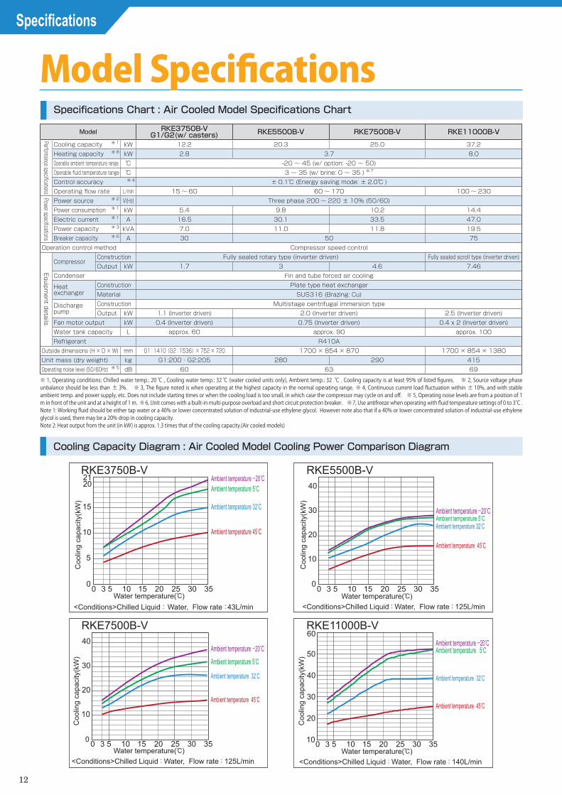
Cooling capacity ※ 1 kW 12.2 20.3 25.0 37.2Heating capacity ※ 8 kW 2.8 3.7 8.0Operable ambient temperature range ℃ -20 ~ 45 (w/ option: -20 ~ 50)Operable fluid temperature range ℃ 3 ~ 35 (w/ brine: 0 ~ 35 ) ※ 7
Control accuracy ※ 4 ± 0.1℃ (Energy saving mode: ± 2.0℃ )Operating flow rate L/min 15 ~ 60 60 ~ 170 100 ~ 230
Power specifications
Power source ※ 2 V(Hz) Three phase 200 ~ 220 ± 10% (50/60)Power consumption ※ 1 kW 5.4 9.8 10.2 14.4Electric current ※ 1 A 16.5 30.1 33.5 47.0Power capacity ※ 3 kVA 7.0 11.0 11.8 19.5Breaker capacity ※ 6 A 30 50 75
Operation control method Compressor speed control
Equipment details
CompressorConstruction Fully sealed rotary type (inverter driven) Fully sealed scroll type (inverter driven)Output kW 1.7 3 4.6 7.46
Condenser Fin and tube forced air cooling
Heat exchanger
Construction Plate type heat exchangerMaterial SUS316 (Brazing: Cu)
Discharge pump
Construction Multistage centrifugal immersion typeOutput kW 1.1 (Inverter driven) 2.0 (Inverter driven) 2.5 (Inverter driven)
Fan motor output kW 0.4 (Inverter driven) 0.75 (Inverter driven) 0.4 x 2 (Inverter driven)Water tank capacity L approx. 60 approx. 90 approx. 100Refrigerant R410A
Outside dimensions (H × D × W) mm G1:1410(G2:1536)× 752 × 720 1700 × 854 × 870 1700 × 854 × 1380Unit mass (dry weight) kg G1:200・G2:205 280 290 415Operating noise level (50/60Hz) ※ 5 dB 60 63 69
Specifications
Model SpecificationsSpecifications Chart : Air Cooled Model Specifications Chart
Cooling Capacity Diagram : Air Cooled Model Cooling Power Comparison Diagram
※ 1, Operating conditions: Chilled water temp.: 20 ℃ , Cooling water temp.: 32 ℃ (water cooled units only), Ambient temp.: 32 ℃ . Cooling capacity is at least 95% of listed figures. ※ 2, Source voltage phase unbalance should be less than ± 3%. ※ 3, The figure noted is when operating at the highest capacity in the normal operating range. ※ 4, Continuous current load fluctuation within ± 10%, and with stable ambient temp. and power supply, etc. Does not include starting times or when the cooling load is too small, in which case the compressor may cycle on and off. ※ 5, Operating noise levels are from a position of 1 m in front of the unit and at a height of 1 m. ※ 6, Unit comes with a built-in multi-purpose overload and short circuit protection breaker. ※ 7, Use antifreeze when operating with fluid temperature settings of 0 to 3℃ .Note 1: Working fluid should be either tap water or a 40% or lower concentrated solution of industrial-use ethylene glycol. However note also that if a 40% or lower concentrated solution of industrial-use ethylene glycol is used, there may be a 20% drop in cooling capacity.Note 2: Heat output from the unit (in kW) is approx. 1.3 times that of the cooling capacity.(Air cooled models)

13
4-Hanging eyeboltsRKE3750B-V : M10RKE5500/7500B-V : M16
Drain pan drain holeRc1/2
Chilled water outlet
Rc1
Hot air discharge
Airintake
Power cord access port(φ20.5)
D
C
W
Chilled water inletRc1
H
AB±5
17.5 E 17.5
Control panel(Touch panel)Filter
2-12 hole (Anchor attachment hole)Total 4 points (Left and right side)
Total 4 points (Left and right side)
GF
Anchor fastening fitting assembly
Water supplyPJ1/2
Water level gauge
Overflow outletRp1
Water tank drain Rc1/2(With 1/2B valve)※RKE5500/7500B-V Rc 3/4(With 3/4B valve)
684
Reference point 1
Detail of chilled water circuit parts (RKE3750B-V)
192
560
K
622
464434160
1386420
970J
F
RKE3750B-VRKE5500B-VRKE7500B-V
RKE3750B-V-G2(With casters)
LM
Reference point 1
788
209
70
Detail of chilled water circuit parts (RKE5500/7500B-V)
56 148
160568538
K
628
690
191
4-12 hole (Anchor attachment hole)
4-Hanging eyebolts(M16) (Touch panel)
Filter
FilterAnchor fastening fitting assembly
Airintake
Hot air discharge
Airintake
Control panelW D
H
GF
JF
17.5 E 17.5
C
A
B Drain pan drain holeRc1/2
Chilled water outletRc1.1/4
Power cord access port(Up φ30.0, Low φ20.5)
Chilled water inletRc1.1/4
Water supplyPJ1/2
Water level gauge Overflow outletRp1
Water tank drain Rc3/4(With 3/4B valve)
Reference point 1
209
70
789
57
570
508
K20
7149
323293
Detail of chilled water circuit parts (RKE11000B-V)
699
RKE11000B-V
RKE3750B-V RKE5500B-V RKE7500B-V RKE11000B-V
W H A B C D E F G J K L M 720 1410 826 830 708 752 791 330 197 197 115 126 1536 870 1700 975 990 812 854 940 480 121 221 110 - -
1380 1700 1485 1500 812 854 1450 480 123 223 110 - -
ModelExternal dimension table
※ The illustration shows the actual measured flow rate value when the bypass valve is closed.※ Flow rate changes based on inverter frequency※ The shaded area indicates the range possible for the adjusted frequency value.※ The flow rate and pressures indicated are those displayed on the chiller.
RKE3750B-V
10 50
0.50[50]
0.40[40]
0.30[30]
0.20[20]
0.10[10] 0.05[5]0.08[8]
0.50[50]
0.40[40]
0.30[30]
0.20[20]
0.10[10]
0.05[5]0.08[8] 0.08[8]
RKE5500,7500B-V
40 18011060 6015 170
RKE11000B-V
5 15 25 35
RKE3750B-V
0
5
10
15
20
0 3020103
21RKE5500B-V
5 15 25 3500 3020103
10
20
30
40
RKE7500B-V
5 15 25 350 0 3020103
10
20
30
40
RKE11000B-V
5 15 25 350 302010310
20
30
40
50
60
0.00[0]
0.10[10]0.20[20]0.30[30]0.40[40]0.50[50]0.60[60]0.70[70]0.80[80]
90 240230
170100
Water temperature(℃)
Coo
ling
capa
city
(kW
)
<Conditions>Chilled Liquid: Water, Flow rate:43L/min
Ambient temperature -20°CAmbient temperature 5°C
Ambient temperature 32°C
Ambient temperature 45°C
Water temperature(℃)
Coo
ling
capa
city
(kW
)<Conditions>Chilled Liquid : Water, Flow rate : 125L/min
Ambient temperature -20°CAmbient temperature 5°CAmbient temperature 32°C
Ambient temperature 45°C
<Conditions>Chilled Liquid : Water, Flow rate : 125L/minWater temperature(℃)
Coo
ling
capa
city
(kW
)
Ambient temperature -20°CAmbient temperature 5°C
Ambient temperature 32°C
Ambient temperature 45°C
<Conditions>Chilled Liquid : Water, Flow rate : 140L/minWater temperature(℃)
Coo
ling
capa
city
(kW
)
Ambient temperature 45°C
Ambient temperature 32°C
Ambient temperature 5°CAmbient temperature -20°C
Wat
er P
ress
ure
(MPa
) [He
ad(m) ]
Flow rate(L/min) Flow rate(L/min)
Wat
er P
ress
ure
(MPa
) [He
ad(m) ]
Flow rate(L/min)
Wat
er P
ress
ure
(MPa
) [He
ad(m) ]
External Dimensions : Air Cooled Model External Dimensions
Chilled Water Flow Chart

14
Specifications
Specifications Chart : Water Cooled Model Specifications Chart
※ 1, Operating conditions: Chilled water temp.: 20℃ , Cooling water temp.: 32℃ (water cooled units only), Ambient temp.: 32 ℃ . Cooling capacity is at least 95% of listed figures. ※ 2, Source voltage phase unbalance should be less than ± 3%. ※ 3, The figure noted is when operating at the highest capacity in the normal operating range. ※ 4, Continuous current load fluctuation within ± 10%, and with stable ambient temp. and power supply, etc. Does not include starting times or when the cooling load is too small, in which case the compressor may cycle on and off. ※ 5, Operating noise levels are from a position of 1 m in front of the unit and at a height of 1 m. ※ 6, Unit comes with a built-in multi-purpose overload and short circuit protection breaker. ※ 7, Use antifreeze when operating with fluid temperature settings of 0 to 3℃ .Note 1: Working fluid should be either Clean water or a 40% or lower concentrated solution of industrial-use ethylene glycol. However note also that if a 40% or lower concentrated solution of industrial-use ethylene glycol is used, there may be a 20% drop in cooling capacity.
※ Actual cooling water flow rate will depend on the water temperature.
※ Ensure the required quantity of water as shown in the graphs below.
Cooling Capacity Diagram: Air Cooled Model Cooling Power Comparison Diagram
Cooling Water Flow Rate (For the water cooled condenser)
Model RKE3750B-VWG1/G2 (w/ casters) RKE5500B-VW RKE7500B-VW RKE11000B-VW
Performance specifications
Cooling capacity ※ 1 kW 14.1 23.4 27.3 43.0Heating capacity ※ 8 kW 2.8 3.0 3.1 9.1Operable ambient temperature range ℃ 2 ~ 45 (w/ option: 2 ~ 50)Cooling water temperature range ℃ 5 ~ 45Operable fluid temperature range ℃ 3 ~ 35 (w/ brine: 0 ~ 35 ) ※ 7
Control accuracy ※ 4 ± 0.1℃ (Energy saving mode: ± 2.0℃ )Operating flow rate L/min 15 ~ 60 60 ~ 170 100 ~ 230
Power specifications
Power source ※ 2 V(Hz) Three phase 200 ± 10% (50) / 200 ~ 220 ± 10% (60)Power consumption ※ 1 kW 5.1 8.8 10.1 12.7Electric current ※ 1 A 19.2 31.8 33.0 41.0Power capacity ※ 3 kVA 8.0 12.2 12.6 17.5Breaker capacity ※ 6 A 30 50 75
Operation control method Compressor speed control
Equipment details
CompressorConstruction Fully sealed rotary type (inverter driven) Fully sealed scroll type (inverter driven)Output kW 1.7 3 4.6 7.46
Condenser Double pipe water cooling
Heat exchanger
Construction Plate type heat exchangerMaterial SUS316 (Brazing: Cu)
Discharge pump
Construction Multistage centrifugal immersion typeOutput kW 1.1 (Inverter driven) 2.0 (Inverter driven) 2.5 (Inverter driven)
Water tank capacity L approx. 60 approx. 90 approx. 100Refrigerant R410
Outside dimensions (H × D × W) mm G1:1410(G2:1536)× 752 × 720 1700 × 854 × 870 1410 × 854 × 1380Unit mass (dry weight) kg G1:200・G2:205 280 290 390Operating noise level (50/60Hz) ※ 5 dB 58 59
RKE3750B-VW
10 50
0.50[50]
0.40[40]
0.30[30]
0.20[20]
0.10[10] 0.05[5]0.08[8]
0.50[50]
0.40[40]
0.30[30]
0.20[20]
0.10[10]
0.05[5]0.08[8] 0.08[8]
RKE5500,7500B-VW
40 18011060 6015 170
RKE3750,5500,7500,11000B-VW
4.04.55.05.56.06.5
2.53.03.5
2.01.51.00.50 5 4510 15 20 25 30 35 40
5 15 25 350
5
10
15
20
0 3020103
RKE3750B-VW
5 15 25 350
0 3020103
10
20
30
40
RKE5500B-VW
5 15 25 350
0 3020103
RKE7500B-VW
10
20
30
40
RKE11000B-VW
5 15 25 350 302010310
20
30
40
50
60
RKE11000B-VW
0.00[0]
0.10[10]0.20[20]0.30[30]0.40[40]0.50[50]0.60[60]0.70[70]0.80[80]
90 240230
170100
Water temperature(℃)
Coo
ling
capa
city
(kW
)
<Conditions>Chilled Liquid : Water, Flow rate : 43L/min
Cooling water
tempera
ture
at intake
5°C
Cooling water temperature
at intake 32°C
Cooling water temperature
at intake 45°C
Water temperature(℃)
Coo
ling
capa
city
(kW
)
<Conditions>Chilled Liquid : Water, Flow rate : 125L/min
Cooling water temperature
at intake 5°C
Cooling water temperature
at intake 32°C
Cooling water temperature
at intake 45°C
<Conditions>Chilled Liquid : Water, Flow rate : 125L/min
Water temperature(℃)
Coo
ling
capa
city
(kW
)
Cooling water temperature
at intake 5°C
Cooling water temperature
at intake 32°C
Cooling water temperature
at intake 45°C
<Conditions>Chilled Liquid : Water, Flow rate : 140L/min
Water temperature(℃)
Coo
ling
capa
city
(kW
)
Cooling water temperature
at intake 45°C
Cooling water temperature
at intake 5°C
Cooling water temperature
at intake 32°C
<Conditions> Cooling water temperature:35℃Cooling water temperature at intake(℃)
Coo
ling
Wat
er F
low
Rat
e(㎥
/h)
RKE7500B-VW RKE11000B-VW
RKE3750B-VWRKE5500B-VW
Wat
er P
ress
ure(
MPa
) [He
ad(m) ]
Flow rate(L/min) Flow rate(L/min)
Wat
er P
ress
ure(
MPa
) [He
ad(m) ]
Flow rate(L/min)
Wat
er P
ress
ure(
MPa
) [He
ad(m) ]
RKE3750B-VW
10 50
0.50[50]
0.40[40]
0.30[30]
0.20[20]
0.10[10] 0.05[5]0.08[8]
0.50[50]
0.40[40]
0.30[30]
0.20[20]
0.10[10]
0.05[5]0.08[8] 0.08[8]
RKE5500,7500B-VW
40 18011060 6015 170
RKE3750,5500,7500,11000B-VW
4.04.55.05.56.06.5
2.53.03.5
2.01.51.00.50 5 4510 15 20 25 30 35 40
5 15 25 350
5
10
15
20
0 3020103
RKE3750B-VW
5 15 25 350
0 3020103
10
20
30
40
RKE5500B-VW
5 15 25 350
0 3020103
RKE7500B-VW
10
20
30
40
RKE11000B-VW
5 15 25 350 302010310
20
30
40
50
60
RKE11000B-VW
0.00[0]
0.10[10]0.20[20]0.30[30]0.40[40]0.50[50]0.60[60]0.70[70]0.80[80]
90 240230
170100
Water temperature(℃)
Coo
ling
capa
city
(kW
)
<Conditions>Chilled Liquid : Water, Flow rate : 43L/min
Cooling water
tempera
ture
at intake
5°C
Cooling water temperature
at intake 32°C
Cooling water temperature
at intake 45°C
Water temperature(℃)
Coo
ling
capa
city
(kW
)
<Conditions>Chilled Liquid : Water, Flow rate : 125L/min
Cooling water temperature
at intake 5°C
Cooling water temperature
at intake 32°C
Cooling water temperature
at intake 45°C
<Conditions>Chilled Liquid : Water, Flow rate : 125L/min
Water temperature(℃)
Coo
ling
capa
city
(kW
)
Cooling water temperature
at intake 5°C
Cooling water temperature
at intake 32°C
Cooling water temperature
at intake 45°C
<Conditions>Chilled Liquid : Water, Flow rate : 140L/min
Water temperature(℃)
Coo
ling
capa
city
(kW
)
Cooling water temperature
at intake 45°C
Cooling water temperature
at intake 5°C
Cooling water temperature
at intake 32°C
<Conditions> Cooling water temperature:35℃Cooling water temperature at intake(℃)
Coo
ling
Wat
er F
low
Rat
e(㎥
/h)
RKE7500B-VW RKE11000B-VW
RKE3750B-VWRKE5500B-VW
Wat
er P
ress
ure(
MPa
) [He
ad(m) ]
Flow rate(L/min) Flow rate(L/min)
Wat
er P
ress
ure(
MPa
) [He
ad(m) ]
Flow rate(L/min)
Wat
er P
ress
ure(
MPa
) [He
ad(m) ]RKE3750B-VW
10 50
0.50[50]
0.40[40]
0.30[30]
0.20[20]
0.10[10] 0.05[5]0.08[8]
0.50[50]
0.40[40]
0.30[30]
0.20[20]
0.10[10]
0.05[5]0.08[8] 0.08[8]
RKE5500,7500B-VW
40 18011060 6015 170
RKE3750,5500,7500,11000B-VW
4.04.55.05.56.06.5
2.53.03.5
2.01.51.00.50 5 4510 15 20 25 30 35 40
5 15 25 350
5
10
15
20
0 3020103
RKE3750B-VW
5 15 25 350
0 3020103
10
20
30
40
RKE5500B-VW
5 15 25 350
0 3020103
RKE7500B-VW
10
20
30
40
RKE11000B-VW
5 15 25 350 302010310
20
30
40
50
60
RKE11000B-VW
0.00[0]
0.10[10]0.20[20]0.30[30]0.40[40]0.50[50]0.60[60]0.70[70]0.80[80]
90 240230
170100
Water temperature(℃)
Coo
ling
capa
city
(kW
)
<Conditions>Chilled Liquid : Water, Flow rate : 43L/min
Cooling water
tempera
ture
at intake
5°C
Cooling water temperature
at intake 32°C
Cooling water temperature
at intake 45°C
Water temperature(℃)
Coo
ling
capa
city
(kW
)
<Conditions>Chilled Liquid : Water, Flow rate : 125L/min
Cooling water temperature
at intake 5°C
Cooling water temperature
at intake 32°C
Cooling water temperature
at intake 45°C
<Conditions>Chilled Liquid : Water, Flow rate : 125L/min
Water temperature(℃)
Coo
ling
capa
city
(kW
)
Cooling water temperature
at intake 5°C
Cooling water temperature
at intake 32°C
Cooling water temperature
at intake 45°C
<Conditions>Chilled Liquid : Water, Flow rate : 140L/min
Water temperature(℃)
Coo
ling
capa
city
(kW
)
Cooling water temperature
at intake 45°C
Cooling water temperature
at intake 5°C
Cooling water temperature
at intake 32°C
<Conditions> Cooling water temperature:35℃Cooling water temperature at intake(℃)
Coo
ling
Wat
er F
low
Rat
e(㎥
/h)
RKE7500B-VW RKE11000B-VW
RKE3750B-VWRKE5500B-VW
Wat
er P
ress
ure(
MPa
) [He
ad(m) ]
Flow rate(L/min) Flow rate(L/min)
Wat
er P
ress
ure(
MPa
) [He
ad(m) ]
Flow rate(L/min)
Wat
er P
ress
ure(
MPa
) [He
ad(m) ]

15
External Dimensions : Water Cooled Model External Dimensions
※ The illustration shows the actual measured flow rate value when the bypass valve is closed.※ Flow rate changes based on inverter frequency※ The shaded area indicates the range possible for the adjusted frequency value.※ The flow rate and pressures indicated are those displayed on the chiller.
RKE3750B-VW
10 50
0.50[50]
0.40[40]
0.30[30]
0.20[20]
0.10[10] 0.05[5]0.08[8]
0.50[50]
0.40[40]
0.30[30]
0.20[20]
0.10[10]
0.05[5]0.08[8] 0.08[8]
RKE5500,7500B-VW
40 18011060 6015 170
RKE3750,5500,7500,11000B-VW
4.04.55.05.56.06.5
2.53.03.5
2.01.51.00.50 5 4510 15 20 25 30 35 40
5 15 25 350
5
10
15
20
0 3020103
RKE3750B-VW
5 15 25 350
0 3020103
10
20
30
40
RKE5500B-VW
5 15 25 350
0 3020103
RKE7500B-VW
10
20
30
40
RKE11000B-VW
5 15 25 350 302010310
20
30
40
50
60
RKE11000B-VW
0.00[0]
0.10[10]0.20[20]0.30[30]0.40[40]0.50[50]0.60[60]0.70[70]0.80[80]
90 240230
170100
Water temperature(℃)
Coo
ling
capa
city
(kW
)
<Conditions>Chilled Liquid : Water, Flow rate : 43L/min
Cooling water
tempera
ture
at intake
5°C
Cooling water temperature
at intake 32°C
Cooling water temperature
at intake 45°C
Water temperature(℃)
Coo
ling
capa
city
(kW
)
<Conditions>Chilled Liquid : Water, Flow rate : 125L/min
Cooling water temperature
at intake 5°C
Cooling water temperature
at intake 32°C
Cooling water temperature
at intake 45°C
<Conditions>Chilled Liquid : Water, Flow rate : 125L/min
Water temperature(℃)
Coo
ling
capa
city
(kW
)
Cooling water temperature
at intake 5°C
Cooling water temperature
at intake 32°C
Cooling water temperature
at intake 45°C
<Conditions>Chilled Liquid : Water, Flow rate : 140L/min
Water temperature(℃)
Coo
ling
capa
city
(kW
)
Cooling water temperature
at intake 45°C
Cooling water temperature
at intake 5°C
Cooling water temperature
at intake 32°C
<Conditions> Cooling water temperature:35℃Cooling water temperature at intake(℃)
Coo
ling
Wat
er F
low
Rat
e(㎥
/h)
RKE7500B-VW RKE11000B-VW
RKE3750B-VWRKE5500B-VW
Wat
er P
ress
ure(
MPa
) [He
ad(m) ]
Flow rate(L/min) Flow rate(L/min)
Wat
er P
ress
ure(
MPa
) [He
ad(m) ]
Flow rate(L/min)
Wat
er P
ress
ure(
MPa
) [He
ad(m) ]
Chilled Water Flow Chart
RKE5500B-VWRKE7500B-VW RKE3750B-VW
34
N
Cooling water drain hole Rp1/4(With plug)
Cooling water inletRc1
Freeze prevention valve
Cooling water outletRc1
Water level gauge
Drain pan drain holeRc1/2
Power cord access port(φ20.5)
Chilled water outletRc1Chilled water inlet
Rc1
Control panel(Touch panel)
Water supplyPJ1/2
Overflow outletRp1
Water tank drain Rc1/2(With 1/2B valve)
Anchor fastening fitting assemblyAnchor fastening fitting assembly
Anchor fastening fitting assembly
H
2-12 hole (Anchor attachment hole)Total 4 points (Left and right side)
2-12 hole (Anchor attachment hole)Total 4 points (Left and right side)
GF
JF
4-Hanging eyebolts(M10)
4-Hanging eyebolts(M16)
C
DW
AB±5
17.5 E 17.5
684
Reference point 1
Detail of chilled water circuit parts (RKE3750B-VW)
192
560
K
622
464434160
1386420
970
RKE3750B-VW-G2(With casters)
LM
Referencepoint 1
788
209
70
Detail of chilled water circuit parts (RKE5500/7500B-VW)
56 148
160568538
K
628
690
191
RKE3750B-VW RKE5500B-VW RKE7500B-VW RKE11000B-VW
W H A B C D E F G J K L M N 720 1410 826 830 708 752 791 330 197 197 115 126 1536 869 870 1700 975 990 812 854 940 480 121 221 110 - - 939
1380 1410 1485 1500 812 854 1450 480 123 223 110 - - ※
ModelExternal dimension table
※See External dimensions
4-Hanging eyebolts(M16)
W D
H
GF
JF
17.5 E 17.5
C
A
B Drain pan drain holeRc1/2
Cooling water drain holeRp3/8(With plug)
Power cord access port(Up φ30.0, Low φ20.5)
Chilled water inlet
Water level gauge
Chilled water outlet
Rc1.1/4Rc1.1/4
Cooling water outletRc1.1/4
Cooling water inletRc1.1/4
Water supply
Freeze prevention valve
PJ1/2Overflow outletRp1
Water tank drain Rc3/4(With 3/4B valve)
Detail of chilled water circuit parts (RKE11000B-VW)
Reference point 1
209
207
70789701
57
570
508
K20
7149
323293699
RKE11000B-VW
※RKE5500/7500B-VW Rc 3/4(With 3/4B valve)
RKE3750B-VWRKE5500B-VWRKE7500B-VW

Important Unloading andPlacement Information
16
● Before UnloadingAfter unpacking, check the nameplate of the unit to ensure it is the correct model ordered. Also, check that the below mentioned included parts are present.
● Choice of Installation LocationChoose an installation location that is free from combustible mater ia ls , areas that could lead to e lectr ic shock , or environments that could lead to unit breakdown.
Machine Part Name Specifications Qty Per UnitY-strainer 40 mesh equiv. 1 pc
Barrel nipple
1B × 100L(to attach the Y-strainer)Model:RKE3750 ~ 7500B-V/B-VW
1 pc1.1/4B × 100L(to attach the Y-strainer)
Model:RKE11000B-V/B-VW
It is possible that the unit could be damaged during shipping, transport, or other handling. When receiving the unit, check to make sure that there are no scratches or other abnormalities. If any damage or abnormality is detected, please contact the dealer where the unit was purchased.
Install on a level surface that can adequately support the weight of the unit and fix the unit down with anchor bolts to prevent it from moving around. Not properly installing the equipment as indicated can result in water leaks or injury etc., from the unit tipping over or falling.1. Ensure there is adequate space for heat ventilation as well
as sufficient space for maintenance and inspection of the unit. Also note that if the unit is enclosed as in the illustration below, exhaust heat from the unit will be forced back into the unit, causing the refrigerant pressure to rise, and eventually causing the unit to stop.
2. If the unit will be installed where a wind of 8m/s or higher will be blown on it, measures to block the wind from hitting the unit such as installation of a wind-break panel or wall is required.
3. Install out of direct sunlight and do not install where the unit would be affected by heat. Contact with direct sunlight or heat
Installation of this equipment should be performed by your dealer or other qualified personnel. Improper installation by the end user may lead to water leakage, electric shock, and fire.
● Unloading ProcedureThe unit is heavy; please be careful when transporting it. The unit has rectangular slots at its base in order to accept forklift tines. When lifting the unit by forklift, make sure the forklift tines go through the forklift slots all the way and protrude from the other side of the unit.
ModelMass
(when water tank is empty)
RKE3750B-VW-G1:No casters 200kg
RKE3750B-VW-G2:Casters included 205kg
RKE5500B-V/VW 280kgRKE7500B-V/VW 290kg
RKE11000B-V 415kgRKE11000B-VW 390kg
Forklift slot
ForkliftBase
WARNINGWARNING
CAUTION
CAUTION=
Suspensioneyebolt60°or greater
Pre-unloading and unloading procedures
Water Supply and Drainage Construction
Unit Placement
Exhaust heat
Re-absorption
Re-absorption
200cm or more(Air cooled only)
80cm or more
80cm or more80cm or more
Upper barrier (Roof, eaves, ceiling, etc.)
※ If there are no obstacles within 150cm of the front and sides of the unit, then the space from the top of the unit to the obstacle above can be as low as 100cm or higher.
45℃
-20℃
● Reliably install water supply and drainage piping. Improper water supply and drainage construction could result in water spraying out, causing water damage to the surrounding area.
● Keep water supply pressure at or below 0.50 MPa. Too high pressure can lead to equipment damage, which may lead to water leaks, flooding of the surrounding area, and electric shock.
● Keep the cooling water pressure below 0.69MPa. Higher pressure may damage the components to cause water leakage and may result in electric shock.
Important Unloading and Placement Information
● When performing water piping, be careful to avoid the following points. Failure to do so can result in water leakage. 1. Overtightening the piping connected to the water supply port. 2. Having external forces on the water supply port. 3. Piping installation that does not absorb vibrations of water hammer, etc.
● When connecting piping to the water supply port, always use two tools, using one to support the ball tap valve, as shown in the illustration to the right.
WARNING=Failure to follow instructions contained in a WARNING may result in death or serious injury.
Failure to follow instructions contained in a CAUTION may result in injury to the operator or damage to property.
When making use of the eyebolts, suspend the unit from all 4 eyebolts and make sure there is at least a 60° angle between the top face of the unit and each of the suspension cables. Improper suspension may lead to the unit tipping over or falling, which could result in injury.
can cause the unit to perform below specified performance equal to the amount of that exposure. It can also lead to the activation of built-in safety devices which will prevent unit operation.
4. Air cooled: Operate the unit in the ambient temperature of -20℃~ 45℃ . Operating outside this temperature range can lead to breakdown of the compressor. And operating in temperatures over 45℃ will result in a drop in the effectiveness of thermal radiation of the condenser. Built-in safety devices may activate causing the unit to shut down. If the ambient temperature will be above 45℃ , install ducting, following the section on page 18, "Ducting Design Points". Water cooled: Operate the unit in the ambient temperature of 2℃~ 45℃ . Operating outside this temperature range can lead to breakdown of the compressor.
When performing ductwork, install such that the piping is not constricted along the way. Failure to follow this rule can also lead to activation of built-in safety devices which will stop unit operation.
5. Install in a place that is generally free of dust and dirt. Installation in places with heavy dust and dirt can result in reduction of unit performance.
6. Note that operating air-cooled models solely in the Snow-Protection Mode in areas that heavy snowfall will result in reduced performance. It is therefore recommended that the unit be installed away from falling snow. (Air cooled only)
7. Operate the product at a cooling water temperature within the range of 5℃ to 45℃ . If operated outside the specified range, the safety device will be activated to shoutdown the product. It can also cause the compressor to malfunction. (Water cooled only)

17
Chilled Water / Cooling Water Piping
Electrical Wiring
● Piping SizesPiping diameters for each model are listed below.
9. Always support water supply piping with support fittings, and make sure that piping is horizontal.
● Pipe Connection Procedure (Water cooled) 1. Confirm the positions of the Cooling Water inlet and outlet.
The Cooling Water inlet and outlet are specified with stickers. (“Cooling Water inlet”, “Cooling Water Outlet”)
2. Follow the instructions below for piping work.(1) Mount the Cooling Water inlet valve ① and the Cooling
Water outlet valve ② .(2) Be sure to mount the safety relief valve ③ . The regulating
valve that is installed in the cooling water circuit performs the opening and closing of the valve automatically by detecting the refrigerant pressure. Thus, there is a possibility that the regulating valve becomes full-closed during operation. Be sure to install the safety relief valve for the water leakage prevention in the cooling water circuit, and set the cooling water inlet pressure 0.69MPa or lower.
(3) Install the purge/drain valve ④ .(4) Be sure to install the union coupling ⑤ . Make sure that
the product and the cooling water piping can be easily disassembled when carrying out the cleaning of water-cooled condenser inside the product.
● Piping MethodsPiping installation should follow the guidelines below.1. Check the cooling water inlet and outlet side ports.2. Make pipe lengths as short as possible, and also avoid vertical
and curved piping as much as possible.3. When tightening piping connections, use 2 pipe wrenches or
adjustable wrenches in order to grasp both sides of the joint.4. Always install valves (customer supplied) at the chilled water
inlet and outlet ports.5. Install the included Y-strainer on the chilled water intake side
port.6. Make sure that there is no excessive weight or vibration
directed on the unit from the connected piping. long horizontal piping should be supported with additional support hardware to ensure unreasonable forces are not applied directly to the unit's connection ports. Failure to properly support piping can lead to equipment damage.
7. Piping should be insulated. (Install the pipe insulation such that there is enough gap to allow the removal of the cabinet water supply port.)
8. If an automatic water supply system is to be insta l led , be sure to install a valve on the supply port. Also, keep water supply pressure at or below 0.50MPa.
● Correct Wiring InstallationWhen performing electrical wiring, be sure to carefully follow the guidelines listed below.
Piping ItemPiping Size
RKE3750B-V/VW RKE5500B-V/VWRKE7500B-V/VW RKE11000B-V/VW
Chilled water inlet Rc1 Rc1.1/4Chilled water outlet Rc1 Rc1.1/4
Water tank drain Rc1/2 Rc3/4Overflow port Rp1Drain pan drain port Rc1/2Water supply port PJ1/2Cooling water inlet Rc1(Water cooled only) Rc1.1/4(Water cooled only)
Cooling water outlet Rc1(Water cooled only) Rc1.1/4(Water cooled only)
Y-strainer
Support fittings
Horizontal pipeDrain valve
Chilledwater inlet
Chilledwater outlet
Main unit
1. Chose a power cable based on the breaker capacity shown in the table to the right. Hook up the ground wire to the earth (ground) terminal located in the distribution box. Also, regarding the power and signal terminal block, refer to the chart on the right for the screw size and terminal block width.
2. There is a combined use overload protection and earth leakage breaker installed inside the distribution box and the specifications are in the table to the right.
3. Route the power cord through the power cord access hole, located on the lower-right part of the unit, to the inside of the terminal box. (Use 1 of the 2 available power cord access holes. The other can be used for remote control panel connections, etc.) Connect the power cord to the L1 , L2 , and L3 terminals on the terminal block. Fix the power cord in place with a cable tie.
4. Always properly ground this unit. Connect the ground wire to a proper earth/ground point that has been installed by a qualified electrician. Furthermore, the diameter of the grounding wire must be at least 2㎟ . ※ Prepare the ground wire terminal of a size according to the screw size listed in the table to the right.
5. Ensure the source voltage is within ± 10% of the specified voltage. Also make sure the source voltage phase unbalance
【IMPORTANT】■ Make sure the power cord does not come into contact with the
refrigerant piping or any motor within the unit. Contact with hot surfaces could cause the cord to melt, resulting in an electrical short. (Secure the power cable with the cable tie inside the distribution box.)
■ Never operate the unit when the water circuit is empty. Always fill the water tank and confirm the water level before operating.
■ Do not attempt to perform withstand voltage tests or insulation resistance tests. Doing so can damage the semiconductors used in the chiller control board or inverter. If the tests are deemed necessary, please consult with your dealer.
RKE3750B-V/VW RKE5500、7500B-V/VW RKE11000B-V/VWBreaker capacity (A) 30 50 75Current sensitivity (mA) 30 30 30
RKE3750B-V/VW RKE5500B-V/VW RKE7500B-V/VW RKE11000B-V/VW
Power Source(V・Hz)
Aircooled Three phase 200 ~ 220 ± 10% (50/60)
Water cooled Three phase 200 ± 10% (50)、200 ~ 220 ± 10% (60)
Terminal
block
Screwsize
Power M5 M6Signal M3
Terminalblock width (mm)
Power 12 13 17
Signal 5.9
is within ± 3%. ※ Phase unbalance (%) = ( Maximum voltage [V] - Minimum voltage [V] ) ÷ Average voltage of 3 phases (V) × 67. (Based on IEC61800-3.)
RKE3750、5500、7500B-V/VW RKE11000B-V/VWGround terminal M5 M6
Remote and signal output
Cable tie
Communications connector
Power connection terminals
Ground terminal
⑤Union Coupling②Cooling-Water outlet valve
Cooling-Water outlet
Cooling-Water inlet③Safety relief valve
①Cooling-Water inlet valve
⑥Cooling-Water drain port
④Purge/drain valve

Important Unloading andPlacement Information
18
● Ducting Design Points (For User Installed Ducting)If the area where the unit is to be installed is narrow or has a low ceiling, the ambient temperature could raise to above 45℃ from the heat coming from the ventilation outlet. In such cases, ducting should be used to move the heat outside of the room or at least away from the unit so that the effects of it do not cause the temperature around the unit to rise. Take the following into consideration when planning duct work.
1.Duct cross sectional area(1) For duct that rises up:
RKE3750B-V RKE5500,7500B-V RKE11000B-VMinimum cross sectional
area (㎡ ) [B × W] 0.429 0.611 0.429 × 2
Maximum length (m) 20 20 20(2) Rectangular ducting with bends:○ The cross sectional area should be greater than above, and Lx
and Ly should be less than 2m. (See Fig. 1.)○ If the length of Lx and Ly go over 2 m, then there should be a
20 cm gap between the hot exhaust air outlet from the unit
Ducting Design Points (Air cooled only)
Ly
Lx
B WLy
Lx
B W
Model RKE3750B-V RKE5500,7500B-V RKE11000B-V
Recommended fan
50Hz power EWF-50FTA(Mitsubishi Electric Corporation)
EJ-80FTC3(Mitsubishi Electric Corporation)
EWF-50FTA(Mitsubishi Electric Corporation)× 2
60Hz power EWG-50ETA(Mitsubishi Electric Corporation)
EWG-60FTA(Mitsubishi Electric Corporation)
EWG-50ETA(Mitsubishi Electric Corporation)× 2
Minimum required airflow (m³/min) 119 186 119 × 2
【IMPORTANT】Do not have anything such as walls or other obstacles that could obstruct exhaust output within 2m of the unit in the direction of the duct exhaust output. Failure to follow this rule will result in decreased air flow, the main unit heat ventilation will be insufficient, and built-in safety devices may activate, which would cause unit operation to stop.
Duct
Lx
LyB W
20cm
Chiller
▼ Fig. 1 Examples of bent rectangular ducting.
Rectangular duct with straight bend Rectangular duct with round bend
▼ Fig. 2.: Duct insta l la t ion method when Lx and Ly exceed 2m.
and a fan should be installed on the duct outlet. Do not allow Lx and Ly to be longer than 5m. (See Fig. 2.)
※ The duct in the figure is one example. The particular direction the duct exhaust port goes from the unit does not matter, however the following important points must be enforced.
● When Using Communications Functions
● Communications Cables and Connectors1. USB
① Compatible connector: Type B (male) connector② Maximum cable length: 3m. However, it may be shorter
depending on actual operating conditions.2. RS-422A (RS-485)
(1) Connector: Terminal block(2) Cable Gauge: AWG16 ~ 26 (Use AWG18 ~ 24 if 2 wires
are to be inserted into a single terminal connection.)(3) Length of Insulation to Remove From Cable: 10 mm(4) Attaching the Cables: Use either of the following methods:
Attach the stripped wires as is. When performing hookups, be careful not to allow frayed wires to come into contact with or short out nearby wiring.
(5) Maximum Cable Length: 100 m or less -- May differ depending on operating conditions.
(6) Connection Example ※ If connecting via RS-422A/485, make the connection by
purchasing and using an RS-232C/422A converter.
Example of Commercially Available Connector : Network Supply Inc. GPNET232-485CT (Main Unit) GP-259RS (DOS/V PC 9-Pin Connector), SFN-830(AC Adapter)
USB・ Connector: USB type B connector・ Data cable max. length: 3m.※ May differ depending on specific operating
conditions.
RS-422A(RS-485)
・ Attach the stripped wires and use as is.・ Data cable wire size: AWG16 ~ 26・ Data cable max. length: 100m. (from host to
terminal end)※ May differ depending on specific operating
conditions.
TransmitReceive
Transmit
Receive
12345
12345
12345
RS422A/485
Device addressNo.00
USB、RS-232C/422Aconverter Device address
No.01Device address
No.02
…
maximum 32 units
If Employing Remote Control Operation
1. Please confirm the unit specifications which are as follows.
2. Remote operation and signal output terminals are as follows:
Remote operation input specifications
・ No-voltage contacts input (alternate switch)・ Maximum cable length: 20m・ Input resistance: 1200 Ω・ Open circuit voltage (Voc): DC12V・ Short circuit current (Isc): DC10mA
Signal output specifications
・ No-voltage relay contact output (c contact)・ 250VAC / 30VDC 5A (resistance load) (normally
open)・ 250VAC / 30VDC 3A (resistance load) (normally
closed)・ Minimum operating current (for reference only)
5VDC 10mA
Remote operation terminals
Remote operation
2021
Remote discharge pump operation
22
23
Signal output
terminals
Operating signal
24 When power source is cut off: 24-26 closed, 25-26 open
25 Unit operation is stopped and the unit is operating in pump-only mode: 24-26 closed, 25-26 open
26 Equipment operating: 24-26 open, 25-26 closed
Alarmsignal
27 When power source is cut off: 27-29 closed, 28-29 open28 No alarm : 27-29 closed, 28-29 open (initial setting)29 During alarm: 27-29 open, 28-29 closed (initial setting)
Temp. Warning Signal
30 When power source is cut off: 30-32 closed, 31-32 open31 No temperature warning: 30-32 closed, 31-32 open (initial setting)32 During temperature warning: 30-32 open, 31-32 closed (initial setting)
● Information Regarding Remote Operation and Communications Functions
Perform the wiring after confirming the required specifications.※ Please prepare terminals that fit M3 size screws.

19
5. Operating with antifreeze rust inhibitor additives can reduce the lifespan of the mechanical seals.
● Water SelectionWater for the water-cooled condenser may be ground water, municipal water, or cooling-tower water. Refer to the following information for guidance in selecting the water type.
● Water Quality Standard GuidelinesPrimary cooling water (refrigeration unit condenser cooling water, constant temperature water for the water temperature controller, and humidification water) should meet the water quality standard as described in the chart on the right 1. Standard Concentration Levels for Primary Cooling Water
(1) If tap water is used as the primary cooling water for water cooled equipment, then the water should meet the following water quality standard.
(2) “○” marks in a tendency column show the factor related to either corrosion or scale generation tendency.
(3) The 15 items listed to the right are the primary components that can lead to corrosion or scaling.
【IMPORTANT】Do not operated with the discharge pump circuit (cooling water inlet/outlet) blocked. Operating the unit with the circuit blocked can result in freezing or damage of the evaporator, breakdown of the discharge pump, disconnection of hoses, or other trouble.■ If a brine solution is to be used for freeze prevention then in
order to maintain cooling capacity, using a 40 % or weaker solution of ethylene glycol and water is recommended. However, note that use of a solution of 30 % or less can result in decomposition of the fluid. Therefore freeze-prevention by means of automatic pump operation is recommended.
■ Frequent starting and stopping can lead to unit breakdown. Allow at least 5 minutes between starting and stopping the unit. If the unit is started less than 5 minutes after stopping, warning "C064" or "C065" will be generated.
■ Always fill the water tank and check the water level before operating. If the water level gauge goes below the "E" mark, alarm "E006" will occur and the unit cannot be operated.
■ The water pressure at the water supply port should be 0.50MPa or less. Too high pressure will result in the water supply failing to shut off or leakage.
■ Always keep the water clean, inspect the water circuits monthly, and replace the water when necessary.
■ Clean the condenser filter every month. ■ Water cooled: The cooling water should be checked monthly to
ensure that it is clean. The water should be changed if dirty.
● Chilled Water StandardsThe liquid which can be chilled (chilled water) can be either clean water (see chart below for water quality standard) or an industrial-use ethylene glycol and water solution of 40% (max.) or less. Alternatively, if RO treated (deionized) water is to be used, it
Cooling Water
Points to Follow to Achieve Performance Specifications
ClauseCooling Water Tendencies
Circulation water
Supplied water Corrosion Scaling
Standard Item
s
pH (25℃ ) 6.5 to 8.2 6.0 to 8.0 ○ ○Electric conductivity (µS/cm) (25℃ ) 800 or below 300 or below ○ ○Chloride ion (mgCI - /L) 200 or below 50 or below ○Sulfate ion (mgSO4
2 - /L) 200 or below 50 or below ○Acid consumption (pH4.8) (mgCaC3/L) 100 or below 50 or below ○Total hardness (mgCaCO3/L) 200 or below 70 or below ○Calcium hardness (mgCaCO3/L) 150 or below 50 or below ○Ionic Silica (mgSiO2/L) 50 or below 30 or below ○
Reference Item
s
Iron (mgFe/L) 1.0 or below 0.3 or below ○ ○Cu (mgCu/L) 0.3 or below 0.1 or below ○Sulfide ion (mgS2 - /L) None detected None detected ○Ammonium ion (mgNH4
+/L) 1.0 or below 0.1 or below ○Residual chlorine (mgCI/L) 0.3 or below 0.3 or below ○Free carbon dioxide (mgCO2/L) 4.0 or below 4.0 or below ○Stability index 6.0 to 7.0 ー ○ ○
* Excerpt from JRA-GL-02-1994 guidelines from The Japan Refrigeration and Air Conditioning Industry Association.
Item Standard levels
Standard
components
pH(25℃) 6.8 ~ 8.0Conductivity ( μ S/cm) (25℃ ) 1 ~ 400Chloride ion (mgCI-/L) Max. 50Sulphate (mgSO4
2-/L) Max. 50Acid consumption (pH4.8) (mgCaCO3/L) Max. 50Total hardness (mgCaCO3/L) Max. 70Calcium hardness (mgCaCO3/L) Max. 50Silica ion (mgSiO2/L) Max. 30
● Installing Ducting on the UnitIf ducting is to be affixed to the unit, first remove the suspension eyebolts from the top and replace them with M size bolts of the appropriate size. In this case, in order to allow for easy fan maintenance and inspection, allow for at least 50cm of removal space above the unit.
【IMPORTANT】● If ducting is to be affixed directly on the unit, be sure to install support hardware along the ducting in order to prevent the unit from tipping over.
Model A B C D E M screwRKE3750B-V 720 725 655 654.6 35.3 M10
RKE5500,7500B-V 869.5 825.2 804.5 758.6 31.5 M16RKE11000B-V 1379 827 1314.2 758.6 33.7 M16
Unit:mm
B D B D
35.1
E E
32.5AC
AC
32.5
4-M screw
FrontFront
32.4 32.4
34.7
4-M screw
RKE11000B-V
RKE3750B-VRKE5500B-VRKE7500B-V
Item Standard levels
Reference
components
Iron (mgFe/L) Max. 1.0Copper (mgCu/L) Max. 1.0Sulfide ion (mgS2-/L) Not detectedAmmonium ion (mgNH4
+/L) Max. 1.0Residual chlorine (mgCI/L) Max 0.3Free carbon dioxide (mgCO2/L) Max. 4.0
* Excerpt from JRA-GL-02-1994 guidelines from The Japan Refrigeration and Air Conditioning Industry Association.
should have a conductivity of at least 1 μ S/cm. Cooling non-approved fluids can result in equipment damage, leaking, and possible electric shock or electrical shorts.
● Important Points to Ensure Optimum Product Performance1. Note the operating ranges and always operate the unit within
these ranges. Operating outside the designated ranges can lead to unit breakdown.
Clause RKE3750、5500、7500B-V/VW RKE11000B-V/VWAmbient temp. range (℃ ) -20 ~ 45 (Air cooled) / 2 ~ 45 (Water cooled)
Fluid temp. range (℃ ) 3 ~ 35
Power (V・Hz)200~220±10% (50/60:Air cooled)
200±10% (50:Water cooled)、200~220±10% (60:Water cooled)
Discharge pump operating pressure (Mpa) 0.08 ~ 0.50 0.08 ~ 0.80
2. Do not use aluminum parts for parts that will be wetted with the chilled water or cooling water. The unit's water circuits operate with parts made of copper or copper alloys, so if user-installed wetted parts containing aluminum are present, the resulting copper ions will lead to electrolytic corrosion and copper deposits, which can cause water leakage around mechanical seals and clogging in the heat exchanger.
3. Please consult your dealer before using any corrosion inhibiting water additives. Troubles such as the water becoming dirty, or damage to the refrigeration unit from clogging etc. can result depending on the type of additive used.
4. Always apply power to the unit at least 12 hours before performing initial test runs or after the unit has been unpowered for 24 hours or more. Failure to apply power in advance as directed can lead to damage to the refrigeration compressor.
Chilled Water
ORION is continuing to develop a complete and trustworthy nationwide network of expedient sales and service -- everywhere, anytime.
*ORION has wide reaching regional service bases in various countries throughout the world. Please consult your ORION dealer for details.
ORION MACHINERY CO., LTD.ORION MACHINERY CO., LTD.
ISO 9001ISO 14001
ISO (International Organization for Standardization) is an established body that stipulates and certifies ISO9001 and ISO14001 directives. ISO9001 stipulates a system of Quality Management that ensures customer satisfaction and trust in a company's products and services it provides. ISO14001 stipulates a system of Environmental Management whereby production and business activities are carried out in an environmentally conscious manner.
What is the ISO certification system?
ORION Machinery Co., ltd is an ISO Certified, QualityManagement and Environmental Management company.
(Main Factory)
Please feel free to contact the following representative:ー
No. 246, Kotaka, Suzaka-shi, Nagano-ken, 382-8502 JapanTEL(026)246-5664 FAX(026)246-6753e-Mail: [email protected]
International Division
No. 246, Kotaka, Suzaka-shi, Nagano-ken, 382-8502 JapanTEL(026)245-1230 FAX(026)245-5424URL: http://www.orionkikai.co.jp
Head Office& Factory
This catalogue contains product specifications as of April, 2016●Actual product colors may vary slightly from the pictures.● The structure or specifications of products contained in this catalogue are subject to change without prior notice.
K No.1993 160526 PDF SR ☆50
Orion Products -- Service and Safety
● Safety Notes1. Before using this equipment, read the operating
manual thoroughly and operate the equipment correctly as directed.
2. Consult with a qualified professional or your ORION dealer for product installation and wiring.
3. Please select a product that is suitable for the desired application. Do not use for other than intended purposes. Use for other than intended purposes can lead to accidents or unit breakdown.
● Air-Cooled Spec. ModelsIf the condenser becomes clogged with dust or dirt, heat exchange will be greatly reduced and electricity consumption will increase. This will lead not only to decreased performance, but can also lead to the activation of built-in safety devices, and eventual damage to the equipment. For these reasons, the condenser should be cleaned on a regular basis.
● Water-Cooled Spec. ModelsIn general, water used to cool condensers will be well water, tap water, or water from a cooling tower. However water of insufficient quality can lead to scaling in cooling pipes resulting in lower levels of heat exchange, increased electricity consumption and lower performance. Therefore water quality should be confirmed on a regular basis.
● Product Use Limitations1. If the unit is to be used as part of critical installations, safety
devices and backup systems which can be switched to should be put into place to insure that serious accidents or losses do not occur in the event that the unit should break down or malfunction.
2. This product is designed and produced as a commodity for general manufacturing. Accordingly, the warranty does not apply to nor cover the following applications. However, in cases where the customer/user takes full responsibility and confirms the performance of the equipment in advance, and takes necessary safety precautions, please consult with ORION and we will consider if use of the unit in the desired application is appropriate.(1) Atomic energy, aviation, aerospace, railway works, shipping,
vehicles (cars and trucks), medical applications, transportation applications, and/or any applications where it might have a great effect on human life or property.
(2) Electricity, gas, or water supply systems, etc. where high levels of reliability and safety are demanded.
●Recirculating Chilled WaterFor chilled water, please use either clean water or a low concentration ethylene glycol water solution of 40% or less. In case of use of deioninzed water, keep the electric conductivity at 1 microsiemens/cm or above. If the quality of chilled water does not fall within the guidelines, it may result in damage of the mechanical seals, water leaks, electric leak/shock, etc.
Regarding After Service● Please contact your dealer for any repairs required
after using this unit.● Costs will be incurred by the customer for repairs
conducted after the warranty period has expired. In cases where equipment function can be improved by certain service procedures, such procedures will be taken at the specific request of the customer.
● Spare parts are items necessary to maintain the proper function and operating specifications of the equipment. It is the policy of ORION to maintain a stock of replacement parts for 7 years after production of the product ceases.
Recommended Maintenance Inspections● After having used the unit for a long time, actual
performance may drop due to the effects of dirt or wear, etc. In order to realize continued best performance of this equipment, in addition to prescribed customer maintenance, it is also recommended that regular inspections be conducted. (Service and inspection fees apply.) For further information please consult with your dealer or contact ORION directly.