heatexchangers
TRANSCRIPT

Heat Transfer Equipments

ROLL NO -67
BATCH - I

Objectives
Recognize what is heat exchanger
Differentiate numerous types of heat exchanger, their classification and their applications
Know the heat transfer equipment terminologies
Know the primary consideration in the selection of heat exchangers

What is a heat transfer equipment? An equipment that permits efficient transfer of heat
from a hot fluid to a cold fluid without any or with direct contact of fluids
Such an equipment is called
Heat Exchanger

What is a Heat Exchanger?
Technically speaking ……
A heat exchanger is a device that is used to
transfer thermal energy (enthalpy) between
two or more fluids, between a solid surface and
a fluid,
or between solid particulates and a fluid,
at different temperatures
and in thermal contact.
Heat Exchanger
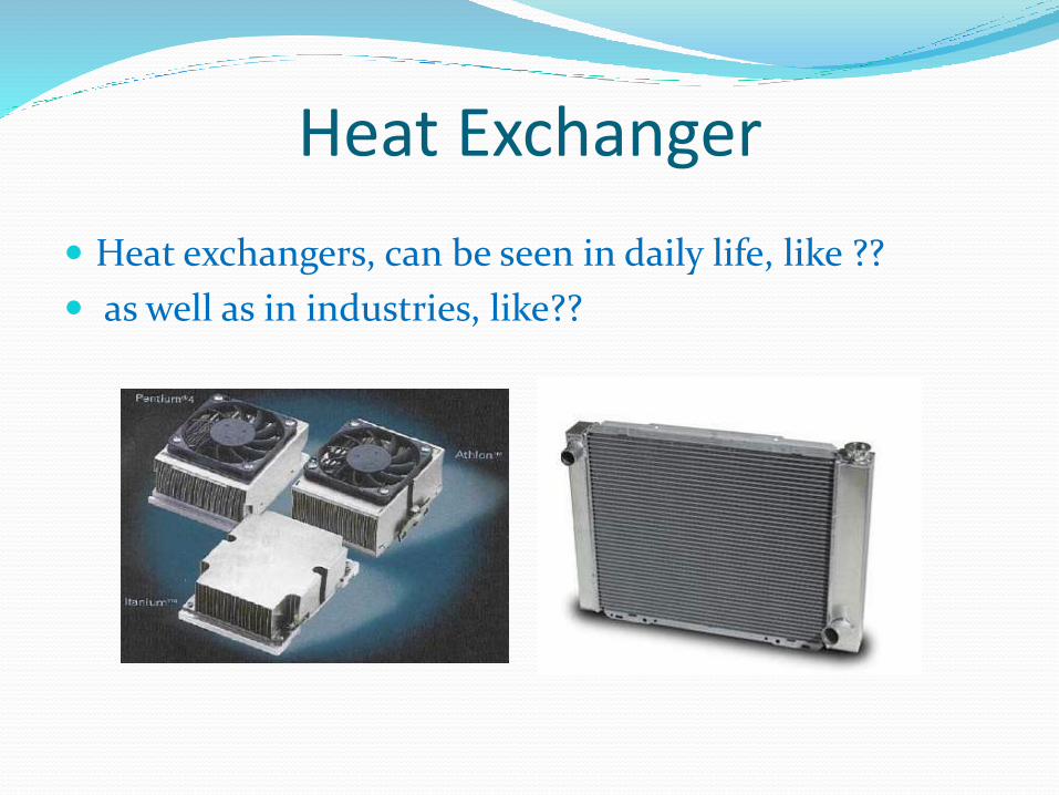
Heat exchangers, can be seen in daily life, like ??
as well as in industries, like??

Aim and Application of HE
Typical applications involve heating or cooling of a fluid stream of concern and evaporation or condensation of single- or multicomponent fluid streams.
In other applications, the objective may be to recover or reject heat, or sterilize, pasteurize, fractionate, distill, concentrate, crystallize, or control a process fluid.
Common examples of heat exchangers are shell-and tube exchangers, automobile radiators, condensers, evaporators, air preheaters, and cooling towers.

Aim and Application of HEHeat exchanger found applications in almost all
Chemical and petrochemical plants
Air Conditioning Systems
Power production
Waste Heat recovery
Automobile Radiator
Central Heating System
Electronic Parts

Different Terminologies of Heat Transfer Equipment
Heat exchanger: both sides single-phase and process streams
Cooler: one stream a process fluid and the other cooling water or air.
Heater: one stream a process fluid and the other a hot utility, such as steam or hot oil.
Condenser: one stream a condensing vapor and the other cooling water or air.
Chiller: one stream a process fluid being condensed at sub-atmospheric temperatures and the other a boiling refrigerant or process stream.
Reboiler: one stream a bottoms stream from a distillation column and the other a hot utility (steam or hot oil) or a process stream.

Heat Exchanger ClassificationHeat exchangers are classified according to
Transfer process
Number of fluids
Degree of surface compactness
Construction
Flow arrangements
Heat transfer mechanisms

Shah, 1981
Heat Exchanger ClassificationHeat exchangers are classified according to
Transfer process

Classification by Transfer Processes

Classification by Transfer Processes
1. Indirect contact type The fluid streams remain separate and the heat transfers continuously through a dividing wall into and out of the wall in a transient manner.

Classification by Transfer Processes
1. Indirect contact type a) Direct transfer type heat exchanger
b) Storage type heat exchanger
c) Fluidized bed heat exchanger

Classification by Transfer Processesa) Direct Transfer Type Heat Exchanger In this, type heat transfers continuously from the hot fluid to
the cold fluid through a dividing wall.
There is no direct mixing of the fluids because each fluid flows in separate fluid passages.
It is also known as recuperator. Examples, tubular exchangers, plate and frame heat exchangers and extended surface exchangers.
Tubular Exchanger Plate and Frame Exchanger

Classification by Transfer Processesb) Storage Type Heat Exchanger (Regenerative Heat
Exchanger)
Fixed Bed Regenerator
Continuous-passage matrices for a rotary regenerator: (a) notched plate; (b) triangular passage.
Classification by Transfer Processes
b) Storage Type Heat Exchanger (Regenerative Heat Exchanger)
Regenerative heating was one of the most important technologies developed during the Industrial Revolution when it was used in the hot blast process on blast furnaces.
It was later used in glass and steel making, to increase the efficiency of open hearth furnaces, and in high pressure boilers and chemical and other applications, where it continues to be important today.

Classification by Transfer Processesc) Fluidized bed heat exchanger
In a fluidized-bed heat exchanger, one side of a two-fluid exchanger is immersed in a bed of finely divided solid material, such as a tube bundle immersed in a bed of sand or coal particles.
The common applications of the fluidized-bed heat exchanger are drying, mixing, adsorption, reactor engineering, coal combustion, and waste heat recovery

Classification by Transfer Processes2. Direct-Contact Heat Exchanger
In a direct-contact exchanger, two fluid streams come into direct contact, exchange heat, and are then separated.
Common applications of a direct-contact exchanger involve mass transfer in addition to heat transfer, such as in evaporative cooling and rectification.
However, the applications are limited to those cases where a direct contact of two fluid streams is permissible.

Classification by Transfer Processes
2. Direct-Contact Heat Exchangera) Immiscible Fluid Exchangers
b) Gas–Liquid Exchangers
c) Liquid–Vapor Exchangers

Classification by Transfer Processes
a) Immiscible Fluid Exchangers In this type, two immiscible fluid streams are brought into
direct contact.
These fluids may be single-phase fluids, or they may involve condensation or vaporization.
Condensation of organic vapors and oil vapors with water or air are typical examples.

Classification by Transfer Processesb) Gas–Liquid Exchangers In this type, one fluid is a gas (more commonly, air) and
the other a low-pressure liquid (more commonly, water) and are readily separable after the energy exchange.
In either cooling of liquid (water) or humidification of gas (air) applications, liquid partially evaporates and the vapor is carried away with the gas.
In these exchangers, more than 90% of the energy transfer is by virtue of mass transfer (due to the evaporation of the liquid), and convective heat transfer is a minor mechanism.
A ‘‘wet’’ (water) cooling tower with forced- or natural-draft airflow is the most common application.
Other applications are the air-conditioning spray chamber, spray drier, spray tower, and spray pond.

Classification by Transfer Processes
c) Liquid–Vapor Exchangers In this type, typically steam is partially or fully
condensed using cooling water, or water is heated with waste steam through direct contact in the exchanger.
Noncondensables and residual steam and hot water are the outlet streams.
Common examples are desuperheaters and open feedwater heaters (also known as deaerators) in power plants.

Classification by Transfer Processes2. Direct-Contact Heat ExchangerCompared to indirect contact recuperators and regenerators, in direct-contact heat exchangers,
(1) very high heat transfer rates are achievable,
(2) the exchanger construction is relatively inexpensive, and
(3) the fouling problem is generally nonexistent, due to the absence of a heat transfer surface (wall) between the two fluids.
Heat Exchanger ClassificationHeat exchangers are classified according to
Number of fluids

Classification by Number of Fluid
Most processes of heating, cooling, heat recovery, and heat rejection involve transfer of heat between two fluids.
Hence, two-fluid heat exchangers are the most common.
Three fluid heat exchangers are widely used in cryogenics and some chemical processes (e.g., air separation systems, a helium–air separation unit, purification and liquefaction of hydrogen, ammonia gas synthesis).
Heat exchangers with as many as 12 fluid streams have been used in some chemical process applications.

Heat Exchanger ClassificationHeat exchangers are classified according to
Degree of surface compactness

Classification by Surface Compactness β
Heat exchangers are characterized by a large heat transfer surface area per unit volume of the exchanger, resulting in
reduced space,
reduce weight,
reduce support structure and footprint,
energy requirements and cost,
as well as improved process design
and plant layout and processing conditions, together with low fluid inventory.
Classification by Surface Compactness β
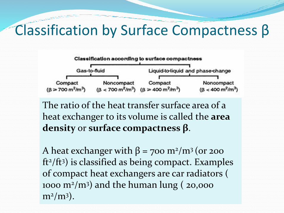
The ratio of the heat transfer surface area of a heat exchanger to its volume is called the area density or surface compactness β.
A heat exchanger with β = 700 m2/m3 (or 200 ft2/ft3) is classified as being compact. Examples of compact heat exchangers are car radiators ( 1000 m2/m3) and the human lung ( 20,000 m2/m3).

Heat Exchanger ClassificationHeat exchangers are classified according to
Heat Transfer Mechanisms

Classification by Heat Transfer Mechanisms
The basic heat transfer mechanisms employed for transfer of thermal energy from the fluid on one side of the exchanger to the wall (separating the fluid on the other side) are single-phase convection (forced or free), two-phase convection (condensation or evaporation, by
forced or free convection), and combined convection and radiation heat transfer.
Any of these mechanisms individually or in combination could be active on each fluid side of the exchanger.
Some examples of each classification type are automotive radiators, passenger space heaters, regenerators, intercoolers, economizers and so on.

Heat Exchanger ClassificationHeat exchangers are classified according to
Flow arrangements

Classification by Flow Arrangement

Classification by Flow Arrangement
The choice of a particular flow arrangement is dependent on the required exchanger
effectiveness,
available pressure drops,
minimum and maximum velocities allowed,
fluid flow paths,
packaging envelope,
allowable thermal stresses,
temperature levels,
piping and plumbing considerations,
and other design criteria.

Classification by Flow ArrangementSingle Pass flow arrangementA fluid is considered to have made one pass if it flows through a section of the heat exchanger through its full length.
a) Counterflow exchanger
• In a counterflow or countercurrent exchanger, the two fluids flow parallel to each other but in opposite directions within the core.
• The counterflow arrangement is thermodynamically superior to any other flow arrangement.
• It is the most efficient flow arrangement, producing the highest temperature change in each fluid compared to any other two-fluid flow arrangements for a given overall thermal conductance (UA), fluid flow rates and fluid inlet temperatures.
• The maximum temperature difference across the exchanger produces minimum thermal stresses in the wall for an equivalent performance compared to any other flow arrangements.

Classification by Flow Arrangement
Single Pass flow arrangementb) Parallelflow exchanger
• In a parallelflow (also referred to as cocurrent or cocurrent parallel stream) exchanger, the fluid streams enter together at one end, flow parallel to each other in the same direction, and leave together at the other end.
• This arrangement has the lowest exchanger effectiveness among single-pass exchangers for given overall thermal conductance and fluid flow rates and fluid inlet temperatures.
• In a parallelflow exchanger, a large temperature difference between inlet temperatures of hot and cold fluids exists at the inlet side, which may induce high thermal stresses in the exchanger wall at the inlet.

Classification by Flow Arrangement
Single Pass flow arrangementc) Crossflow Exchanger
• In this type of exchanger, the two fluids flow in directions normal to each other.
• Thermodynamically, the effectiveness for the crossflow exchanger falls in between that for the counterflow and parallel flow arrangements.
• The largest structural temperature difference exists at the ‘‘corner’’ of the entering hot and cold fluids.
• This is one of the most common flow arrangements used for extended surface heat exchangers, because it greatly simplifies the header design at the entrance and exit of each fluid.

Classification by Flow Arrangement
Single Pass flow arrangementd) Splitflow Exchanger
• In this exchanger, the shell fluid stream enters at the center of the exchanger and divides into two streams.
• These streams flow in longitudinal directions along the exchanger length over a longitudinal baffle, make a 180° turn at each end, flow longitudinally to the center of the exchanger under the longitudinal baffle, unite at the center, and leave from the central nozzle.
• The other fluid stream flows straight in the tubes.

Classification by Flow Arrangement
Multipass flow arrangement
After flowing through one full length, if the flow direction is reversed and fluid flows through an equal- or different-sized section, it is considered to have made a second pass (or multipass) of equal or different size.

Heat Exchanger ClassificationHeat exchangers are classified according to
Construction

Classification by constructionTubular
Double pipe
Shell and tube
Spiral tube
Pipe coils
Plate type Plate and frame
Spiral
Plate coil
Printed circuit
Extended surface Plate-fin
Tube-fin
Regenerative
Rotary
Fixed-matrix
Rotating hoods

Shell and Tube HE

Double Pipe HE

Plate and Frame HE

Plate-Fin HE


Study Reference Materials Fundamentals of Heat Exchanger Design. Ramesh K.
Shah and Dušan P. Sekulic, John Wiley & Sons, Inc.
Heat Exchanger Design Handbook. KuppanThulukkanam, CRC Press.
