heat treatmentand properties - u.s. government...
TRANSCRIPT
National Bureau of StandardsLibrary, N.W. Bldg
NBS MONOGRAPH 18
Heat Treatment and Properties
of Iron and Steel
U.S. DEPARTMENT OF COMMERCE
NATIONAL BUREAU OF STANDARDS
THE NATIONAL BUREAU OF STANDARDS
Functions and Activities
The functions of the National Bureau of Standards are set forth in the Act of Congress, March3, 1901, as amended by Congress in Public Law 619, 1950. These include the development andmaintenance of the national standards of measurement and the provision of means and methods for
making measurements consistent with these standards; the determination of physical constants andproperties of materials; the development of methods and instruments for testing materials, devices,
and structures; advisory services to government agencies on scientific and technical problems; inven-
tion and development of devices to serve special needs of the Government; and the development of
standard practices, codes, and specifications. The work includes basic and applied research, develop-
ment, engineering, instrumentation, testing, evaluation, calibration services, and various consultation
and information services. Research projects are also performed for other government agencies
when the work relates to and supplements the basic program of the Bureau or when the Bureau'sunique competence is required. The scope of activities is suggested by the listing of divisions andsections on the inside of the back cover.
Publications
The results of the Bureau's work take the form of either actual equipment and devices or pub-lished papers. These papers appear either in the Bureau's own series of publications or in the journals
of professional and scientific societies. The Bureau itself publishes three periodicals available fromthe Government Printing Office: The Journal of Research, published in four separate sections,
presents complete scientific and technical papers; the Technical News Bulletin presents summary andpreliminary reports on work in progress; and Basic Radio Propagation Predictions provides data for
determining the best frequencies to use for radio communications throughout the world. There are
also five series of nonperiodical pubHcations: Monographs, Apphed Mathematics Series, Handbooks,Miscellaneous Publications, and Technical Notes.
Information on the Bureau's publications can be found in NBS Circular 460, Publications of
the National Bureau of Standards ($1.25) and its Supplement (|1.50), available from the Super-intendent of Documents, Government Printing Office, Washington 25, D.C.
UNITED STATES DEPARTMENT OF COMMERCE . Frederick H. Mueller, Secretary
NATIONAL BUREAU OF STANDARDS • A. V. Astin, Dirictor
Heat Treatment and Properties of
Iron and Steel
Thomas G. Digges and Samuel J. '^senberg
National Bureau of Standards Monograph 18
Issued October 3, 1960
Supersedes Circular 495
For sale by the Superintendent of Documents, U.S. Government Printing Office, Washington 25, D.C, - Price 35 cents
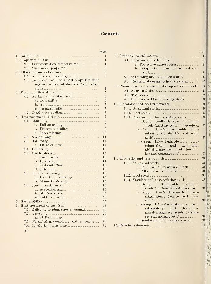
Contents
Page
1. Introduction 1
2. Properties of iron 1
2.1. Transformation temperatures 1
2.2. Mechanical properties 2
3. Alloys of iron and carbon 2
3.1. Iron-carbon phase diagram 2
3.2. Correlation of mechanical properties with
microstructures of slowly cooled carbon
steels 4
4. Decomposition of ausenite 5
4.1. Isothermal transformation 6
a. To pearlite 6
b. To bainite 7
c. To martensite 7
4.2. Continuous cooling 7
5. Heat treatment of steels 8
5.1. Annealing 9
a. Full annealing 9
b. Process annealing 9
c. Spheroidizing 10
5.2. Normalizing 11
5.3. Hardening 11
a. Effect of mass 11
5.4. Tempering 12
5.5 Case hardening 13
a. Carburizing 13
b. Cyaniding 14
c. Carbonitriding 15
d. Nitriding 15
5.6. Surface hardening 15
a. Induction hardening 15
b. Flame hardening 16
5.7. Special treatments 16
a. Austempering 16
b. Martempering 16
c. Cold treatment 16
6. Hardenability 17
7. Heat treatment of cast irons 18
7.1. Relieving residual stresses (aging) 20
7.2. Annealing 20
a. Malleabilizing 20
7.3. Normalizing, quenching, and tempering 20
7.4. Special heat treatments 21
II
8. Practical considerations
8.1. Furnaces and salt baths
a. Protective atmospheres
b. Temperature measurement and con-
trol
8.2. Quenching media and accessories
8.3. Relation of design to heat treatment
9. Nomenclature and chemical compositions of steels.
9.1. Structural steels
9.2. Tool steels
9.3. Stainless and heat resisting steels
10. Recommended heat treatments
10.1. Structural steels
10.2. Tool steels
10.3. Stainless and heat resisting steels
a. Group I—Hardenable chromiumsteels (martensitic and magnetic).
b. Group II—-Nonhardenable chro-
mium steels (ferritic and mag-netic)
c. Group III—-Nonhardenable chro-
mium-nickel and chromium-nickel-manganese steels (austen-
itic and nonmagnetic)
11. Properties and uses of steels
11.1. Structural steels
a. Plain carbon structural steels
b. AUoy structural steels
11.2. Tool steels
11.3. Stainless and heat resisting steels
a. Group I—Hardenable chromiumsteels (martensitic and magnetic).
b. Group II—Nonhardenable chro-
mium steels (ferritic and mag-netic)
c. Group III—Nonhardenable chro-
mium-nickel and chromium-
nickel-manganese steels (austen-
itic and nonmagnetic)
d. Semi-austenitic stainless steels
12. Selected references.
Pag€
21
21
2]
21
21
2ci
2(i
3(
3(
3(
3J
3<'
3.:
3.;
.3cI
3fe
3f
36
3^
ye.
3S1
2,1
3f
3f
4(
Heat Treatment and Properties of Iron and Steel
Thomas G. Digges and Samuel J. Rosenberg
This ^lonograph has been prepared to give an understanding of heat treatment princi-pally to those unacquainted with this subject. To this end, the basic theoretical and practi-cal principles involved in the heat treatment of iron and steel are presented in simplified form.
1. Introduction
The Xational Bureau of Standards receives
many requests for general information concerningthe heat treatment of iron and steel and for direc-
tions and explanations of such processes. ThisMonograph has been prepared to answer suchinquiries and to give in simplified form a workingknowledge of the basic theoretical and practical
principles involved in the heat treatment of iron
and steel. The effects of various treatments onthe structures and mechanical properties of these
materials are described. Many theoretical aspects
are discussed only briefly or omitted entirely, andin some instances, technical details have beenneglected for sunplicity. The present Monographsupersedes Circular 495, which was published in
1950.
Heat treatment may be defined as an operationor combination of operations that involves theheating and cooling of a solid metal or alloy for thepurpose of obtaining certain desirable conditions
^ or properties. It is usually desired to preserve, as
"Inearly as possible, the form, dimensions, and
m surface of the piece being treated.
m Steels and cast irons are essentially alloys ofMjl iron and carbon, modified by the presence of otherm elements. Steel may be defined as an alloy of u'on
3j[i and carbon (with or without other alloymg ele-
ments) containing less than about 2.0 percent of
I carbon, usefidly malleable or forgeable as initially
isj cast. Cast iron may be defined as an alloy of u'on
and carbon (with or without other alloying ele-
ments) containing more than 2.0 percent of carbon,not usefully malleable or forgeable as initially cast.
For reasons that will be apparent later, the divid-
ing line between steels and cast irons is taken at2.0 percent of carbon, even though certam special
steels contain carbon in excess of this amount. Inaddition to carbon, fom^ other elements are nor-
J maUy present in steels and in cast irons. Theseare mangnaese, silicon, phosphorus, and sulfiu".
Steels may be broadly classified into two types,
(1) carbon and (2) alloy. Carbon steels owe their
properties chiefly to the carbon. They are fre-
quently called straight or plain carbon steels.
Alloy steels are those to which one or more alloyingelements are added in sufficient amounts to modifycertain properties. The properties of cast ironalso may be modified by the presence of alloyingelements—such irons are called alloy cast irons.
2. Properties of Iron
Since iron is the basic element of steel, a knowl-edge of some of its properties is a prerequisite to
an understanding of the fimdamental pi"inciples
underlying the heat treatment of steels.
2.1. Transformation Temperatures
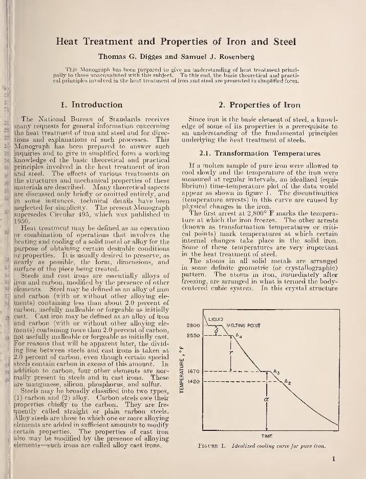
If a molten sample of pure u"on were allowed tocool slowly and the temperature of the iron weremeasured at regular intervals, an idealized (equi-
librium) time-temperature plot of the data wouldappear as shown in figure 1. The discontinuities
(temperature arrests) in this curve are caused byphysical changes in the U'on.
The first arrest at 2,800° F marks the tempera-ture at which the iron freezes. The other arrests
(known as transformation temperatures or criti-
cal points) mark temperatm-es at which certaininternal changes take place in the solid iron.
Some of these temperatures are very importantin the heat treatment of steel.
The atoms in all solid metals are arrangedin some definite geometric (or crystallographic)pattern. The atoms in iron, immediately after
freezing, are arranged in what is termed the body-centered cubic system. In this crystal structure
TIME
Figure 1. Idealized cooling curve for pure iron.
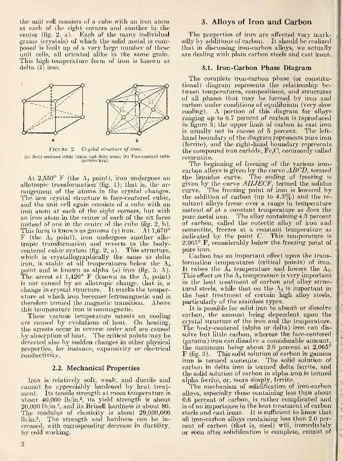
the unit cell consists of a cube with an ii'on atomat each of the eight corners and another in the
center (fig. 2, a). Each of the many individual
grains (crystals) of which the solid metal is com-posed is built up of a very large number of these
unit cells, all oriented alike in the same grain.
This high-temperatui'e form of iron is known as
delta (5) iron.
o b
Figure 2. Crystal structure of iron.
(a) Body-centered cubic (alpha and delta iron); (b) Face-centered cubic(gamma iron).
At 2,550° F (the A4 point), iron undergoes analiotropic transformation (fig. 1); that is, the ar-
rangement of the atoms in the crystal changes.
The new crystal structure is face-centered cubic,
and the unit cell again consists of a cube with aniron atom at each of the eight corners, but with
an iron atom in the center of each of the six faces
instead of one in the center of the cube (fig. 2, b).
This form is known as gamma (7) iron. At 1,670°
F (the A3 point), h-on undergoes another allo-
tropic transformation and reverts to the body-centered cubic system (fig. 2, a). This structure,
which is crystallographically the same as delta
iron, is stable at all temperatures below the A3
point and is known as alpha (a) iron (fig. 5, A).
The arrest at 1,420° F (known as the A2 point)
is not caused by an allotropic change, that is, a
change in crystal structure. It marks the temper-ature at which iron becomes ferromagnetic and is
therefore termed the magnetic transition. Abovethis temperature iron is nonmagnetic.These various temperature arrests on cooling
are caused by evolutions of heat. On heating,
the arrests occur in reverse order and are causedby absorption of heat. The critical points may bedetected also by sudden changes in other physicalproperties, for instance, expansivity or electrical
conductivity.
2.2. Mechanical Properties
Iron is relatively soft, weak, and ductile andcannot be appreciably hardened by heat treat-
ment. Its tensile strength at room temperature is
about 40,000 lb/in.\ its yield strength is about20,000 Ib/in.^, and its Brinell hardness is about 80.
The modulus of elasticity is about 29,000,000Ib/in.^. The strength and hardness can be in-
creased, with corresponding decrease in ductility,
by cold working.
3. Alloys of Iron and Carbon
The properties of iron are affected very mark-edly by additions of carbon. It should be realized
that in discussing iron-carbon alloys, we actuallyare dealing with plain carbon steels and cast irons.
3.1. Iron-Carbon Phase Diagram
The complete iron-carbon phase (or constitu-
tional) diagram represents the relationship be-tween temperatures, compositions, and structures
of all phases that may be formed by iron andcarbon under conditions of equilibrium (very slowcooling). A portion of this diagram for alloys
ranging up to 6.7 percent of carbon is reproducedin figure 3; the upper limit of carbon in cast iron
is usually not in excess of 5 percent. The left-
hand boundary of the diagram represents pure iron
(ferrite), and the right-hand boundary represents
the compound iron carbide, FcsC, commonly called
cementite.The beginning of freezing of the various iron-
carbon alloys is given by the curve ABCD, termedthe liquidus curve. The ending of freezing is
given by the curve AHJECF, termed the solidus
curve. The freezing point of iron is lowered bythe addition of carbon (up to 4.3%) and the re-
sultant alloys freeze over a range in temperatureinstead of at a constant temperature as does the
pure metal iron. The alloy containing 4.3 percent
of carbon, called the eutectic alloy of iron andcementite, freezes at a constant temperature as
indicated by the point C. This temperature is
2,065° F, considerably below the freezing point of
pure iron.
Carbon has an important effect upon the trans-
formation temperatures (critical points) of iron.
It raises the A4 temperature and lowers the A3.
This efl^ect on the A3 temperature is very importantin the heat treatment of carbon and alloy struc-
tural steels, while that on the A4 is important in
the heat treatment of certain high alloy steels,
particularly of the stainless types.
It is possible for solid iron to absorb or dissolve
carbon, the amount being dependent upon the
crystal structure of the iron and the temperature.
The body-centered (alpha or delta) iron can dis-
solve but little carbon, whereas the face-centered
(gamma) iron can dissolve a considerable amount,the maximum being about 2.0 percent at 2,065°
F (fig. 3). This solid solution of carbon in gammairon is termed austenite. The solid solution of
carbon in delta iron is termed delta ferrite, andthe solid solution of carbon in alpha iron is termedalpha ferrite, or, more simply, ferrite.
The mechanism of solidification of iron-carbon
alloys, especially those containing less than about0.6 percent of carbon, is rather complicated andis of no importance in the heat treatment of carbonsteels and cast irons. It is sufficient to know that
all iron-carbon alloys containing less than 2.0 per-
cent of carbon (that is, steel) will, immediatelyor soon after solidification is complete, consist of
2
3600 —
STEELS CAST IRONS
CARBON, %
6.7 % C
FiGT'RE 3. Iron-carbon phase diaqravt.
the single phase austenite. Cast ii-ons will consist
of two phases immediately after solidification
—
austenite and cementite. Under some conditions
this cementite formed on cooling through the tem-perature horizontal ECF will decompose partly or
completely into austenite and grapliite.
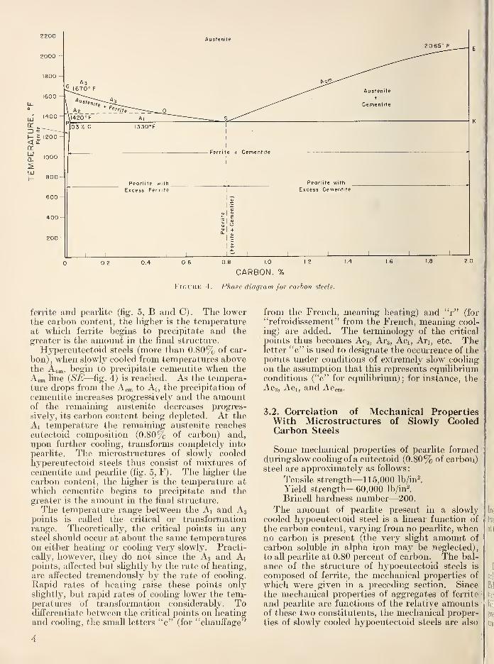
The part of the iron-carbon diagram that is con-
cerned with the heat treatment of steel is repro-
duced on an expanded scale in figure 4. Regard-less of the carbon content, steel exists as austenite
above the line GOSE. Steel of composition S(0.80% of carbon) is designated as "eutectoid"
steel, and those with lower or higher carbon as
"hypoeutectoid" and ''hypereutectoid," respec-
tively.
A eutectoid steel, when cooled at very slow rates
from temperatures within the austenitic field, un-dergoes no change until the temperature horizontal
PSK is reached. At this temperature (known as
the Ai temperature), the austenite transforms com-pletely to an aggregate of ferrite and cementitehaving a typical lamellar structure (fig. 5, D andE). This aggregate is known as pearlite and the
Ai temperature is, therefore, frequently- referred
to as the pearlite point. Since the Ai transforma-
tion involves the transformation of austenite to
pearlite (which contains cementite—FesC), pure
iron does not possess an Ai transformation (fig. 4).
Theoretically, iron must be alloyed with a mini-
mum of 0.03 percent of carbon before the first
minute traces of pearlite can be formed on cooling
(point P, fig. 4). If the steel is held at a tempera-
ture just below A], (either during coohng or
heating), the carbide in the pearhte tends to
coalesce into globules or spheroids. This phe-
nomenon, known as spheroidization, will be dis-
cussed subsequently.Hypoeutectoid steels (less than 0.80% of car-
bon), when slowly cooled from temperatures above
the A3, begin to precipitate ferrite when the A3
line {GOS—fig. 4) is reached. As the temperature
drops from the A3 to Ai, the precipitation of ferrite
increases progressively and the amount of the
remaining austenite decreases progressively^, its
carbon content being increased. At the Ai tem-perature the remaining austenite reaches eutectoid
composition (0.80% of carbon—point S, fig. 4)
and, upon further coohng, transforms completely
into pearlite. The microstructures of slowly cooled
hypoeutectoid steels thus consist of mixtures of
3
2200
2000
1800
1600
2065° F
0,6 08 1-0
CARBON,
%
2.0
Figure 4. Phase diagram for carbon steels.
ferrite and pearlite (fig. 5, B and C). The lowerthe carbon content, the higher is the temperatureat which ferrite begins to precipitate and the
greater is the amount in the final structure.
Hypereutectoid steels (more than 0.80% of car-
bon) , when slowly cooled from temperatures abovethe Acta, begin to precipitate cementite when the
Acm line (SE—fig. 4) is reached. As the tempera-ture di-ops from the Acm to Ai, the precipitation of
cementite increases progressively and the amountof the remaining austenite decreases progres-
sively, its carbon content being depleted. At the
Ai temperature the remaining austenite reacheseutectoid composition (0.80% of carbon) and,upon further cooling, transforms completely into
pearlite. The microstructures of slowly cooledhypereutectoid steels thus consist of mixtures of
cementite and pearlite (fig. 5, F). The higher thecarbon content, the higher is the temperature at
which cementite begins to precipitate and thegreater is the amount in the final structure.
The temperature range between the Ai and A3points is called the critical or transformationrange. Theoretically, the critical points in anysteel should occur at about the same temperatureson either heating or cooling very slowly. Practi-
cally, however, they do not since the A3 and Aipoints, afi^ected but slightly by the rate of heating,
are affected tremendously by the rate of cooling.
Rapid rates of heating raise these points onlyslightly, but rapid rates of cooling lower the tem-peratures of transformation considerably. Todifferentiate between the critical points on heatingand cooling, the small letters "c" (for "chauffage"
from the French, meaning heating) and "r" (for
"refroidissement" from the French, meaning cool-
ing) are added. The terminology of the critical
points thus becomes Acs, Ars, Aci, Ari, etc. Theletter "e" is used to designate the occurrence of thepoints under conditions of extremely slow coolingon the assumption that this represents equihbriumconditions ("e" for equilibrium); for instance, theAcs, Aci, and Accm-
3.2. Correlation of Mechanical PropertiesWith Microstructures of Slowly CooledCarbon Steels
Some mechanical properties of pearlite formedduring slow cooling of a eutectoid (0.80% of carbon)steel are approximately as follows
:
Tensile strength—115,000 Ib/inl
Yield strength—60,000 Ib/inl
Brinell hardness number—200.
The amount of pearlite present in a slowlycooled hypoeutectoid steel is a linear function of
the carbon content, var3dng from no pearlite, whenno carbon is present (the very slight amount of
carbon soluble in alpha iron may be neglected),
to all pearlite at 0.80 percent of carbon. The bal-
ance of the structure of hypoeutectoid steels is
composed of ferrite, the mechanical properties of
which were given in a preceding section. Sincethe mechanical properties of aggregates of ferrite
and pearlite are fimctions of the relative amountsof these two constitutents, the mechanical proper-ties of slowly cooled hypoeutectoid steels are also
4
Fk.i re .3. M iri ostructural constituents of slowly cooled carbon steels.
A, Ferrite (a iron). All grains are of the same composition. XIOO.B, 0.25% carbon. Light areas are ferrite grains. Dark areas are pearlite. XIOO.C, 0.5% carbon. Same as B but higher carbon content results in more pearlite and less ferrite. XIOO.D, 0.8% carbon. All pearUte. XIOO.E, Same as D. At higher magnification the lamellar structure of pearlite is readily observed. XoOO.r, 1.3% carbon. Pearlite plus excess cementite as network. XIOO.All etched with either picral or nital.
linear functions of the carbon content, varying be-tween those of iron at no carbon to those of pearlite
at 0.80 percent of carbon (fig. 6).
4. Decomposition of Austenite
In alloys of iron and carbon, austenite is stableonly at temperatures above the Aei (1,330° F).Below this temperature it decomposes into mix-tures of ferrite (a iron) and cementite (iron car-bidej. The end product or final structui-e is
greatly influenced by the temperature at which thetransformation occurs, and this, in turn, is influ-
enced by the rate of cooling. Since the mechanicalproperties may be varied over a wide range, de-
pending on the decomposition products of the
parent austenite, a knowledge of how austenite
decomposes and the factors influencing it is neces-
sary for a clear imderstanding of the heat treat-
ment of steel. The progressive transformation of
austenite under conditions of equilibrium (ex-
tremely slow cooling) has been described. Prac-ticall}^, however, steel is not cooled underequilibrium conditions, and consequently the
critical points on coohng always occur at lowertemperatoores than indicated in figure 4.
5
120
100
._ 80
60
40
20
200
160
120
80
100
FERR TE .
PEARL.ITE
0.2 0.4 0.6
CARBON, PERCENT
1000.8
Figure 6. Relation of mechanical properties and structureto carbon content of slowly cooled carbon steels.
If samples of steel, say of eutectoid carbon con-tent for the sake of simplicity, are cooled fromabove the Aei at gradually increasing rates, thecorresponding Ar transformation occurs at lowerand lower temperatures (fig. 7). This transfor-mation is distinguished from that occurring underextremely slow rates of cooling (Ai'i) by the desig-nation Ar'. As the rate of cooling of this steel is
increased, an additional transformation (termed theAr" or Ms) appears at relatively low temperatures(about 430° F). If the rate of coohng is still fur-
ther increased, the Ar' transformation is sup-pressed entirely and only the Ar" transformationis evident. It should be noted that the tempera-ture of the Ar" is not affected by the rate of cool-
ing, whereas the temperature of the Ar' may bedepressed to as low as about 1,050° F in this
particular steel.
The product of the Ar' transformation is fine
pearlite. As the temperature of the Ar' is gradu-ally lowered, the lamellar structure of the resultingpearlite becomes correspondingly finer and thesteel becomes harder and stronger. The productof the Ar" transformation is martensite (fig.
9, A, and 15, A), which is the hardest and most
1330
1050
430
AUSTENITE
MARTENSITE
INCREASED RATE OF COOLING
Figure 7. Schematic illustration showing the effect of rate
of cooling on the transformation temperatures and de-composition products of austenite of eutectoid carbonsteel.
brittle of the transformation products of austeniteand is characterized b}^ a typical acicular structure.The phenomenon of the occurrence of both the
Ar' and Ai-" transformations is known as thesplit transformation. The resultant microstruc-tures of steels cooled at such rates as to undergoa split transformation consist of varying amountsof fine pearlite and martensite (fig. 9, C). Theactual amounts of these two constitutents are func-tions of the rates of cooling, the slower rates re-sulting in more pearlite and less martensite, andthe faster rates resulting in more martensite and !
less pearlite.|
4.1. Isothermal Transformation|
The course of transformation of austenite when
'
the steel is quenched to and held at various con- '
stant elevated temperature levels (isothermal,transformation) is conveniently shown by a dia-
gram known as the S-curve (also termed the TTTdiagram—for time, temperature, and transforma-'tion) . Such a diagram for eutectoid carbon steel
'
is shown in figure 8 and the discussion of this
figure will be confined to steel of this particularcomposition.
i
a. To Pearlite,
Austenite containing 0.80 percent of carbon,
'
cooled quickly to and held at 1,300° F, does not f
begin to decompose (transform) until after about15 min, and does not completely decompose until
after about 5 hr (fig. 8). Thus, at temperaturesjust below the Aci, austenite is stable for a con-siderable length of time. The product of tlie
deconxposition of austenite at this temperatm'e is
coarse pearlite of relatively low hardness. If theaustenite is quickly cooled to and held at a some-what lower temperature, say 1,200° F, decomposi-tion begins in about 5 sec and is completed after
6
1400
1200
1000
800
600
400
200
_I[
Ae,
|aUSTEN(TE(A)_
1
0.5 I
TIME, SECONDS
Figure 8. Isothermal transformation diagram (S-curve)
for eutecioid carbon steel.
(Metals Handbook, 1948 edition, page 608.) The hardness of the structuresformed at the various temperatures is given by the scale on the right.
about 30 sec, the resultant pearlite being finer andharder than that formed at 1,300° F. At atemperature of about 1,050° F, the austenite de-composes extremely rapidly, only about 1 sec
elapsing before the transformation starts and 5
sec before it is completed. The restdtant pearlite
is extremel}' fine and its hardness is relatively
high. This region of the S-cm've where decompo-sition of austenite to fine pearlite proceeds so
rapid!}' is termed the "nose" of the cm-ve.
b. To Bainite
If the austenite is cooled unchanged to tempera-tures below the nose of the S-curve (1,050° F), the
time for its decomposition begins to increase (fig.
8). The final product of decomposition now is
not pearlite, but a new acicular constituent called
bainite (fig. 15, E) possessing unusual toughnesswith hardness even greater than that of very fine
pearUte.
Depending on the temperature, then, a certain
finite interval of time is necessary before austenite
starts to transform into either pearhte or bainite.
Additional time is necessar}' before the transfor-
mations are completed.
c. To Martensite
If the austenite is cooled unchanged to relatively
low temperatures (below about 430° F for theeutectoid carbon steel under consideration), partial
transformation takes place instantaneously; theproduct of transformation is martensite. Aus-tenite transforms into martensite over a tem-perature range and the amount that transformsis a function of the temperature. Only minuteamounts will so transform at about 430° F;practically aU of the austenite will be transformedat about 175° F. The beginning of this trans-
formation range is termed the 2vlg (martensite—start) and the end of the range is termed the Mf(martensite—finish). As long as the temperatureis held constant within the Mg—^Mf range, that
portion of the austenite that does not transforminstantaneously to martensite remains untrans-formed for a considerable length of time, eventuallytransforming to bainite.
In ordinary heat treatment of the plain carbonsteels, austenite does not transform into bainite.
Transformation of the austenite takes place either
above or at the nose of the S-cm-ve, forming pearl-
ite, or in passing through the Mg^—Mf range, form-ing martensite, or both. It is evident that in orderfor austenite to be transformed entirely into mar-tensite, it must be cooled sufficiently rapidly so
that the temperature of the steel is lowered past the
nose of the S-curve in less time than is necessaryfor transformation to start at this temperature.
If this is not accomplished, part of the steel trans-
forms into pearlite at the high temperature (Ai-'),
and the remainder transforms into martensite at
the low temperatm-e (Ar" or Mg—Mf temperaturerange). This explains the phenomenon of the
split transformation described previously.
4.2. Continuous Cooling
Figure 9 represents a theoretical S-curve onwhich are supermiposed five theoretical cooling
curves. Cm-ves A to E represent successively
slower rates of cooling, as would be obtained, for
instance, by cooling in iced brine, water, oil, air,
and m the furnace, respectively.
The steel cooled according to cmwe E begins to
transform at temperature ti and completes trans-
formation at the final product is coarse pearlite
with relatively low hardness. When cooled ac-
cording to cm*ve D, transformation begins at Uand is completed at U; the final product is fine
pearlite ancl its hardness is greater than the steel
cooled according to curve E. When cooled ac-
cording to curve C, transformation begins at Uand is only partially complete when temperature
ta is reached; the product of this partial trans-
formation is very fine pearlite. The remainder of
the austenite does not decompose until the Mg tem-perature is reached, when it begins to transform
to martensite, completing this transformation at
the Mf temperature. The final structm-e is then
a mixture of fine pearlite and martensite (typical
of incompletely hardened steel—frequently termed"slack quenched" steel) with a higher hardness
than was obtained with the steel cooled according
to curve D. The rate of cooling represented bycm-ve B is just sufficient to intersect the nose of
the S-cm-ve, consequently only a minute amountof the austenite decomposes into fine pearlite at
temperature i?; the remainder of the austenite is
unchanged until the martensite transforrnation
range is reached. If the steel is cooled at a slightly
faster rate, so that no transformation takes place
at the nose of the S-cm-ve, the steel is completely
hardened. This particular rate is termed the criti-
cal cooling rate and is defined as the slowest rate
at which the steel can be cooled and yet be corn-
pletely hardened. Since this rate cannot be di-
548691—60 2 7
L ". -«a. _.
, ..J
Figure 9. Schematic diagram illustrating the relation be-
tween the S-ciirve, continuous cooling curves, and result-
ing microstructures of eutectoid carbon steel.
Microstructiu-es: A, martensite; B, martensite with a trace of very fine
pearlite (dark); C, martensite and very fine pearlite; D, fine pearlite; E,coarse pearlite. All etched with nital. X500.
rectly determined, the rate indicated by curve B,producing only a trace of fine pearlite (fig. 9, B),is frequently used as the critical cooling rate. Thehardness of the resultant martensite is equivalentto the maximum that can be obtained. Samplescooled at a faster rate, such as that indicated by
cm-ve A, are also completely martensitic but noharder than the sample cooled according to thecritical coolmg rate.
It will be noted that the rate at which a steel
cools tlu-ough the temperature range in the vicinityof the nose of the S-cm-ve is of critical importance.Somewhat slower rates of cooling above and belowthis temperature range can be tolerated and yetobtain a completely hardened steel, provided thatthe cooling through the temperature interval atthe nose of the S-curve is suflSciently fast. Inpractice, however, steels are usually cooled rapidlyfrom the quenching temperature to relatively lowtemperatures (about 500° F) and then allowedto cool in air.
Although the above discussions of the decompo-sition of austenite have been limited to a steel ofeutectoid composition, other steels behave in
a similar manner, the temperatures and times of
reactions being di^fferent. In hypoeutectoid steels,
free ferrite plus pearlite are formed if transforma-tion begins above the temperature range of thenose of the S-curve; the amount of free ferrite
decreases as the temperature of transformationapproaches the nose of the curve. In hypereutec-toid steels, free cementite plus pearlite are formedif transformation occurs above the nose. The timefor the start of the transformation at the nose in-
creases as the carbon increases up to the eutectoidcomposition, and then decreases with further in-
crease in carbon. That is, the nose is shifted to
the right (with respect to the time axis, fig. 8)
as the carbon is increased to 0.8 percent and to
the left with further increase in carbon content,j
The temperature of formation of bainite is not\
appreciably affected by carbon content, but thetime for its formation increases with the carbon.Both the Mg and Mf temperatures are markedly .
lowered by increasing carbon content, as is shownfor Mg in figm-e 10. The Mi temperatures of theplain carbon steels have not been adequately de-termined ; available information indicates that the
Mf of high carbon steels is actually below room <
temperature. Slight amounts of austenite are i
frequently retained in quenched steels, especially:
in the higher carbon grades, even when cooled toi
room temperature. i
5. Heat Treatment of Steels
All heat-treating operatures consist of subject-
ing a metal to a definite time-temperature cycle, '
which may be divided into three parts: (1) Heat- '
ing, (2) holding at temperature (soaking), and '
(3) cooling. Individual cases vary, but certain
fundamental objectives may be stated.
The rate of heating is not particularly important I
unless a steel is in a highly stressed condition, suchas is imparted by severe cold working or prior
hardening. In such instances the rate of heatingshould be slow^. Frequently this is impracticable, j-
since furnaces may be at operating temperatures, i
but placing the cold steel in the hot furnace may i
cause distortion or even cracking. This danger :
8
1000
800
200
0 1 \ \ 1 1 1 1 1
0 0.20 0.40 0.60 0.80 1.00 1.20 1.40
CARBON,
%
Figure 10. Influence of carbon on the start of the marten-site (Ms) transformation of high-purity iron-carbonalloys.
(Dlgges, Trans. Am. Soc. Metals 28, 597 (1940).)
can be ininiinized by the use of a preheatingfurnace maintained at a temperature below the Ai.
The steel, preheated for a sufficient period, thencan be transferred to the fm-nace at operatingtemperature. This procedure is also advantageouswhen treating steels having considerable variations
in section thickness or very low thermal conduc-tivity.
The object of holding a steel at heat-treatingtemperature is to assure uniformity of temperaturethroughout its entire volume. Obviously, thin
sections need not be soaked as long as thicksections, but if different thicknesses exist in thesame piece, the period required to heat the thickest
section uniformly governs the time at temperatm-e.A rule frequently used is to soak % hr/in. of thick-
ness.
The structm-e and properties of a steel dependupon jts rate of coolmg and this, in turn, is gov-erned by such factors as mass, quenching media,etc. It must be realized that the thicker thesection, the slower will be the rate of cooling re-
gardless of the method of cooling used except in
such operations as induction hardening to bediscussed later.
5.1. Annealing
Annealing is a process involving heating andcooling, usually applied to produce softening.
The term also refers to treatments intended to
alter mechanical or physical properties, producea definite microstructm-e, or remove gases. Thetemperature of the operation and the rate of
cooling depend upon the material being annealedand the purpose of the treatment.
a. Full Annealing
Full annealing is a softening process in whicha steel is heated to a temperature above the trans-
formation range (Acs) and, after being held for
a sufficient time at this temperature, is cooledslowly to a temperatm-e below the transformation
range (Ari). The steel is ordinarily allowed tocool slowly in the furnace, although it may beremoved and cooled in some medium such asmica, lime, or ashes, that insm'es a slow rate ofcooling.
Since the transformation temperatures are af-
fected by the carbon content, it is apparent thatthe higher carbon steels can be fully annealed atlower temperatures than the lower carbon steels.
In terms of the diagram shown in figure 4, steels
must be heated to above the Ime GOSK. The tem-perature range normally used for full annealingis 25 to 50 deg F above this line (the uppercritical), as shown in figm'e 11.
Figure 11. Reconnnended temperature ranges for heat
treating plain carbon steels.
The microstructures of the hypoeutectoid steels
that result after full annealmg are quite similar
to those shown for the equilibrium conditions (fig.
5, B and C). Eutectoid and hypereutectoid steels
frec^uently spheroidize partially or completely onfull annealing (see later section and fig. 12, D).
b. Process Annealing
Process annealing, frequently termed stress-
relief annealing, is usually applied to cold-workedlow carbon steels (up to about 0.25% of carbon)
to soften the steel sufficiently to allow fiu-ther cold-
working. The steel is usually heated close to, butbelow, the Aci temperature (fig. 11). If the steel
is not to be further cold-worked, but relief of inter-
nal stresses is deshed, a lower range of tempera-ture will suffice (about 1,000° F). Rate of coohngis immaterial.
This type of anneal will cause recrystallization
and softening of the cold-worked ferrite grains,
but usually will not affect the relatively small
amounts of cold-worked pearlite. Typical struc-
tures of cold-worked, process-annealecl, and fully
annealed low-carbon steel are shown in figure 12,
A, B, and C, respectively.
I
Figure 12. Representative microstructures of carbon steels.
A,':Low carbon steel (0.1% C) as cold-worked. Both ferrite (light) and pearlite (dark) are severely deformed. XIOO.B, Same as (A) after process aimealing at 1,200° F. The ferrite is recrystallized (grains are equi-axed), but pearlite is not affected by this treatment. XIOO.C, Same as (A) after full aimeaUng at 1,650° F. All traces of cold working are eliminated, and the ferrite grains are larger than in (B). XIOO.D, High carbon steel (1.1% 0) as spheroidized. All the carbon is present in the form of spheroids or slightly elongated particles of cementlte in a matrix of
ferrite. X500.E, Hypoeutectoid steel (0.5% G) as normalized at 1,600° F in ?4-in. round (center area). Because of the rapid rate of air cooling such a small section, the
pearlite is quite fine and relatively little free ferrite is formed. X600.F, Same steel as (E) but normalized in IVi-XQ. round (center area). The slower rate of cooling due to the larger section results in coarser pearlite and more
free ferrite. X500.All etched in picral.
c. Spheroidizing
Spheroidizing is a process of heating and cool-
ing steel that produces a rounded or globular formof carbide m a matrix of ferrite. It is usuallyaccomj)lished by prolonged heating at tempera-tures just below the Aci (fig. 11), but may be facil-
itated by alternately heating to temperatures just
above the Aci and cooling to just below the Ari.
The final step, however, should consist of holdingat a temperature just below the critical (Ari). Therate of cooling is immaterial after slowly cooling
to about 1,000° F.
The rate of spheroiclization is affected by the
initial structure. The finer the pearlite, the morereadily spheroidization is accomplished. A marten-sitic structure is very amenable to spheroidization.
This treatment is usually applied to the highcarbon steels (0.60% of carbon and higher). Thepurpose of the treatment is to improve machinabil-ity and it is also used to condition high-carbon steel
for cold-drawing into wire. A typical microstruc-
ture of spheroidized high carbon steel is shownin figure 12, D.
5.2. NormalizingNormalizing is a process in which a steel is
heated, to a temperature above the Acs or the Acm(fig. 11) and then cooled in still aii-. The pm"poseof the treatment is to obliterate the effects of anyprevious heat treatment (including the coarse-
grained structure sometimes resulting from highforging temperatures) or cold-working and to
insure a homogeneous austenite on reheating for
hardening or full annealing. The resultant struc-
tures are pearlite or pearlite with excess ferrite orcementite, depending upon the composition of the
steel. They are different from the structm'es
resulting after annealing in that, for steels of thesame carbon content in the hypo- or hypereutec-toid ranges, there is less excess ferrite or cementiteand the pearlite is finer. These are the results of
the more rapid cooling.
Since the type of structm'e, and, therefore, the
mechanical properties, are affected by the rate of
cooling, considerable variations may occur in
normalized steels because of differences in section
thickness of the shapes being normalized. Theeffect of section thickness on the structure of anormalized 0.5-percent-carbon steel is shown in
figure 12, E and F.
5.3. HardeningSteels can be hardened by the simple expedient
of heating to above the Aca transformation, hold-
ing long enough to insure the attainment of uni-
form temperatm'e and solution of carbon in theaustenite, and then cooling rapidly (quenching).Complete hardening depends on cooling so rapidly(fig. 9, A and B) that the austenite, which other-
wise would decompose on cooling through the Ari,
is maintained to relatively low temperatm-es.When this is accomplished, the austenite trans-
forms to martensite on cooling through the Ms
—
Mi range. Rapid cooling is necessary only to theextent of lowering the temperature of the steel to
well below the nose of the S-curve. Once this hasbeen accomplished, slow cooling from then on,
either in oil or in air, is beneficial in avoiding dis-
tortion and cracking. Special treatments, such as
time quenching and martempering, are designedto bring about these conditions. As martensite is
quite brittle, steel is rarely used in the as-quenchedcondition, that is, without tempering.The maximum hardness that can be obtained
in completely hardened low^-alloy and plain car-
bon structural steels depends primarily on thecarbon content. The relationship of maximumhardness to carbon content is shown in figure 13.
a. Effect of MassPrevious discussion of the formation of marten-
site has neglected the influence of mass. It mustbe realized that even with a sample of relatively
small dimensions, the rate of abstraction of heatis not uniform. Heat is always abstracted fromthe surface layers at a faster rate than from theinterior. In a given cooling medium the coolingrate of both the surface and interior decreases asthe dimensions of a sample increase and the pos-
70
0 I 1 \ \ ! 1 1 1 1 1 1
0 0.10 0.20 0.30 0.40 0.50 0.60 0.70 0.80 0.90 1.00
CARBON ,7o
Figure 13. Relation of maximum attainable hardness ofquenched steels to carbon content.
(Burns, Moore, and Archer, Trans. Am. Soc. Metals 26, 14 (1938)).
sibility of exceeding the critical cooling rate (fig.
9, B) becomes less. To overcome this, the steel
may be quenched in a medium having a veryhigh rate of heat abstraction, such as iced brine,
but, even so, many steels have a physical restric-
tion on the maximum size amenable to completehardening regardless of the quenching medium.The marked effect that mass has upon the hard-
ness of quenched steel may be illustrated by meas-uring the hardness distribution of different size
rounds of the same steel quenched in the samemedium. Curves showing the distribution ofhardness in a series of round bars of different sizes
of 0.5-percent-carbon steel are shown in figure 14.
30
l/2"0
3/4"d
\"d'
1 1/2
\ \ \
f
J
2 10 12RADIUS, INCHES
Figure 14. Variation in hardness in different size roundsof 0.5-percent-carbon steels as quenched from 1,630° Fin water.
(Jomlny, Hardenabillty of alloy steels. Am. Soc. Metals, p. 75, 1939.)
11
The quenching medium used was water; thequenching temperatm-e was 1,530° F. The rate ofcoohng decreased as the diameters of the barsincreased. Only the }^-in. round hardened com-pletely through the cross section, whereas withthe 4-iu. round the critical cooling rate was notattained even at the surface.
5.4. Tempering
Tempering (sometimes called drawing) is theprocess of reheating hardened (martensitic) ornormalized steels to some temperature below thelower critical (Aci). The rate of cooling is im-material except for some steels that are susceptible
to temper brittleness.^
As the tempering temperature is increased, themartensite (fig. 15, A) of hardened steel passesthrough stages of tempered martensite (fi.g. 15, Band C) and is gradually changed into a structureconsisting of spheroids of cementite in a matrix offerrite, formerly termed sorbite (fig. 15, D). These
|
changes are accompanied by a decreasing hardnessand increasing toughness. The tempering temper-^ature depends upon the desired properties and thepurpose for which the steel is to be used. If con-
1 Temper brittleness is manifested as a loss of toughness (observed only by-impact tests of notched bars) after slow cooling from tempering temperaturesof 1,100° F or higher, or after tempering in the temperature range betweenapproximately 850° and 1,100° F. It is most pronounced in alloy steels thatcontain manganese or chromium and usually can be prevented by rapidquenching from the tempering temperature. The presence of molybdenumis beneficial in counteracting the tendency toward temper brittleness.
Figure 15. Microstructures and corresTponding hardness of heat-treated high carbon steel.
A, As quenched in brine; martensite, Rockwell C hardness=67. X500.B, Same as A after tempering at 400° F; tempered martensite, Rocliwell C hardness=61. X500.C, Same as (A) after tempering at 800° F; tempered martensite, Rockwell C hardness=45. X500.D, Same as (A) after tempering at 1,200° F; tempered martensite, Rockwell C hardness=25. X500.E, Quenched in lead at 650° F; bainite, Rockwell C hardness=49. X500.F, Heat-treated steel showing decarburized surface layer (Ught area) that did not respond to hardening. XIOO.All etched in 1% nital.
12
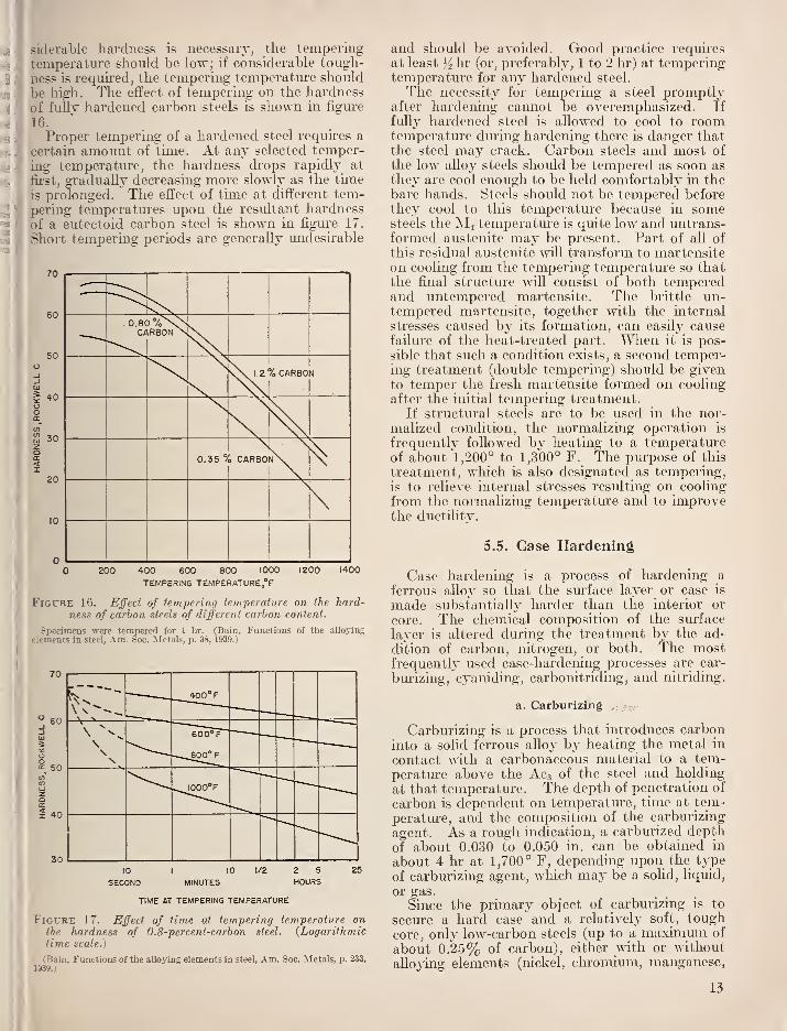
siderable hardness is necessary, the temperingtemperatui-e should be low; if considerable tough-
ness is required, the tempering temperatm-e shoiild
be high. The effect of tempering on the hardness
of fullv hardened carbon steels is shown in figiu-e
16.
Proper tempering of a hardened steel requires a
certain amount of time. At any selected temper-ing temperatiu-e, the hardness drops rapidly at
fii'st, gradually decreasing more slowly as the tune
is prolonged. The effect of time at different tem-pering temperatiu'es upon the residtant hardness
of a eutectoid carbon steel is shown in figm'e 17.
Short tempering periods are generally undesirable
70
60
50
40
30
20
10
*——
^
0.8()7oNNIRBON N
>Ov l.2%CARB0
0.35 °/o CARBO
200 400 600 800 1000
TEMPERING TEMPERATURE °F
1200 1400
Figure 16. Effect of tempering temperature on the hard-ness of carbon steels of different carbon content.
Specimens were tempered for 1 hr. (Bain, Functions of the allojing
elements in steel, Am. Soc. Metals, p. 38, 1939.)
70
60
o: 50
40
30
____400°F
600°F
-_.M0°F
^^^OO^F
10
SECOND
1/2 2 5
HOURS25
TIME AT TEMPERING TEMPERATURE
Figure 17. Effect of time at tempering temperature onthe hardness of 0.8-percenl-carbon steel. {Logarithmictime scaled)
(Bain, Functions of the alloying elements in steel, Am. Soc. Metals, p. 233,
1939.)
and should be avoided. Good practice requires
at least hr (or, preferably, 1 to 2 lir) at temperingtemperature for any hardened steel.
The necessity for tempering a steel promptlyafter hardening cannot be overemphasized. If
fully hardened steel is allowed to cool to roomtemperature dming hardening there is danger thatthe steel may crack. Carbon steels and most of
the low aUoy steels should be tempered as soon as
they are cool enough to be held comfortably in thebare hands. Steels should not be tempered beforethey cool to this temperatm-e because in somesteels the Mi temperatiire is quite low and untrans-formed austenite may be present. Part of all of
this residual austenite will transform to martensiteon cooling from the tempering temperature so thatthe final structure will consist of both temperedand untempered martensite. The brittle un-tempered martensite, together with the internal
stresses caused by its formation, can easily causefailm-e of the heat-treated part. When it is pos-sible that such a condition exists, a second temper-ing treatment (double tempering) should be givento temper the fresh martensite formed on cooling
after the initial tempering treatment.If structmal steels are to be used in the nor-
malized condition, the normalizing operation is
frequently followed by heating to a temperatm-eof about 1,200° to 1,300° F. The purpose of this
treatment, which is also designated as tempering,
is to relieve internal stresses resulting on cooling
from the normalizing temperature and to improvethe ductUity.
5.5. Case Hardening
Case hardening is a process of hardening a
ferrous alloy so that the surface layer or case is
made substantially harder than the interior or
core. The chemical composition of the surface
layer is altered during the treatment by the ad-
dition of carbon, nitrogen, or both. The mostfrequenth' used case-hardening processes are car-
bm-izing, cj'aniding, carbonitriding, and nitriding.
a. Carburizmg
Carbm-izing is a process that introduces carboninto a solid ferrous alloy by heating the metal in
contact with a carbonaceous material to a tem-perature above the Acs of the steel and holding
at that temperature. The depth of penetration of
carbon is dependent on temperature, tmie at tem-perature, and the composition of the carburizing
agent. As a rough indication, a carburized depth
of about 0.030 to 0.050 in. can be obtained in
about 4 hr at 1,700° F, depending upon the type
of carburizing agent, which may be a solid, liquid,
or gas.
Since the primary object of carbm-izing is to
secm-e a hard case and a relatively soft, tough
core, only low-carbon steels (up to a maximum of
about 0.25% of carbon), either with or without
alloying elements (nickel, chromium, manganese,
13
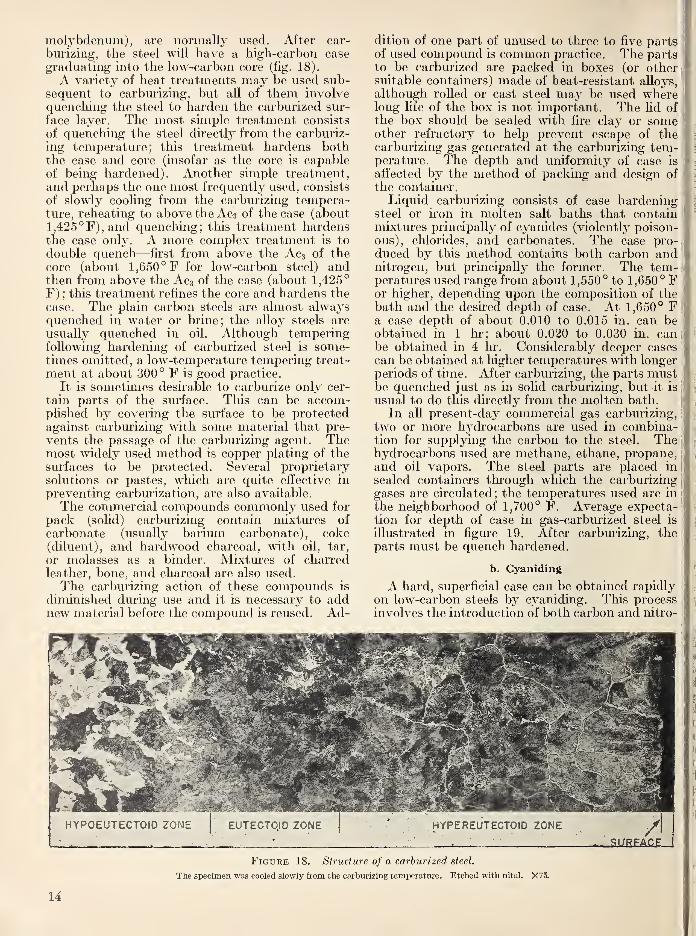
molybdenum), are normally used. After car-
burizing, the steel will have a high-carbon case
graduating into the low-carbon core (fig. 18).
A variety of heat treatments may be used sub-sequent to carburizing, but all of them involvequenching the steel to harden the carburized sur-
face layer. The most simple treatment consists
of quencliing the steel directly from the carburiz-
ing temperature; this treatment hardens boththe case and core (insofar as the core is capableof being hardened). Another simple treatment,and perhaps the one most frequently used, consists
of slowly cooling from the carburizing tempera-ture, reheating to above the Ac3 of the case (aboutl,425°F),and quenching; this treatment hardensthe case only. A more complex treatment is to
double quench—first from above the Aca of the
core (about 1,650° F for low-carbon steel) andthen from above the Acs of the case (about 1,425°
F) ; this treatment refines the core and hardens the
case. The plain carbon steels are almost alwaysquenched in water or brine; the alloy steels are
usually quenched in oil. Although temperingfollowing hardening of carburized steel is some-times omitted, a low-temperature tempering treat-
ment at about 300° F is good practice.
It is sometimes desirable to carburize only cer-
tain parts of the surface. This can be accom-plished by covering the surface to be protectedagainst carburizing with some material that pre-
vents the passage of the carburizing agent. Themost widely used method is copper plating of thesurfaces to be protected. Several proprietarysolutions or pastes, which are quite effective in
preventing carburization, are also available.
The commercial compounds commonly used for
pack (solid) carburizing contain mixtures of
carbonate (usually barium carbonate), coke(diluent), and hardwood charcoal, with oil, tar,
or molasses as a binder. Mixtures of charredleather, bone, and charcoal are also used.
The carburizing action of these compounds is
diminished during use and it is necessary to addnew material before the compound is reused. Ad-
dition of one part of unused to three to five partsof used compound is common practice. The partsto be carburized are packed in boxes (or othersuitable containers) made of heat-resistant alloys,
although rolled or cast steel may be used wherelong life of the box is not important. The Hd ofthe box should be sealed with fire clay or someother refractory to help prevent escape of thecarburizing gas generated at the carburizing tem-perature. The depth and uniformity of case is
affected by the method of packing and design of
the container.
Liquid carburizing consists of case hardeningsteel or iron in molten salt baths that containmixtures principally of cyanides (violently poison-ous), chlorides, and carbonates. The case pro-duced by this method contains both carbon andnitrogen, but principally the former. The tem-peratiu-es used range from about 1,550° to 1,650° For higher, depending upon the composition of the
bath and the desired depth of case. At 1,650° Fa case depth of about 0.010 to 0.015 in. can beobtained in 1 hr; about 0.020 to 0.030 in. canbe obtained in 4 hr. Considerably deeper cases
can be obtained at higher temperatm-es with longerperiods of time. After carburizing, the parts mustbe quenched just as in solid carburizing, but it is
usual to do this directly from the molten bath.
In all present-day commercial gas carburizing,
two or more hydrocarbons are used in combina-tion for supplying the carbon to the steel. Thehydrocarbons used are methane, ethane, propane,and oil vapors. The steel parts are placed in
sealed containers through which the carburizing
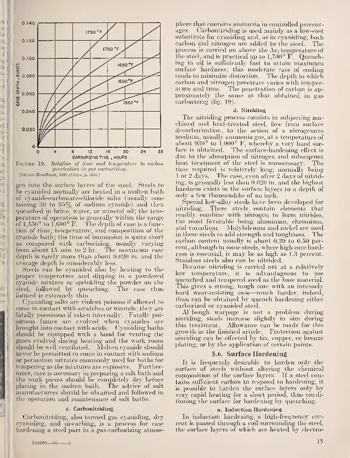
gases are circulated; the temperatures used are in
the neighborhood of 1,700° F. Average expecta-tion for depth of case in gas-carburized steel is
illustrated in figure 19. After carburizing, theparts must be quench hardened.
b. Cyaniding
A hard, superficial case can be obtained rapidly
on low-carbon steels by cyaniding. This processinvolves the introduction of both carbon and nitro-
HYPOEUTEGTOID ZONE
Figure 18. Structure of a carburized steel.
The specimen was cooled slowly from the carburizing temperature. Etched with nital. X75.
14
S 0.080
It-a.
Q 0.060u05<
0.040
0.020
0 l__ 1 1 1 1 1 1 1
0 4 8 12 16 20 24 28
CARBURIZINGTIME , HOURS
Figure 19. Relation of time and temperature to carbonpenetration in gas carhiirizing.
(Metals Handbook, 1939 edition, p. 1041.)
gen into the surface layers of the steel. Steels to
be cyanided normally are heated in a molten bathof cyanide-carbonate-cliloride salts (usually con-taining 30 to 95% of sodium cyanide) and thenquenched in brine, water, or mineral oil; the tem-perature of operation is generally within the rangeof 1 ,550 ° to 1 ,600 ° F. The depth of case is a func-tion of time, temperature, and composition of thecyanide bath; the time of immersion is c^uite short
as compared with carburizing, usually varjangfrom about 15 min to 2 hr. The ma.ximum case
depth is rarely more than about 0.020 in. and theaverage depth is considerably less.
Steels can be cyanided also by heating to the
proper temperatm-e and dipping in a powderedcyanide mixture or sprinkling the powder on thesteel, followed by quenching. The case thusformed is extremely thin.
Cyaniding salts are violent poisons if allowed to
come in contact with scratches or wounds; they are
fatally poisonous if taken internally. Fatally poi-
sonous fumes are evolved when cyanides are
brought into contact with acids. Cyaniding bathsshould be equipped with a hood for venting thegases evolved during heating and the work roomshould be well ventilated. Molten cyanide shouldnever be permitted to come in contact with sodiumor potassium nitrates commonly used for baths for
tempering as the mixtures are explosive. Further-n^ore, care is necessary in preparing a salt bath andthe work pieces should be completely dry before
placing in the molten bath. The advice of salt
manufacturers should be obtained and followed in
the operation and maintenance of salt baths.
c. Carbonitriding
Carbonitriding, also termed gas cyaniding, drycyaniding, and ni-carbing, is a process for case
hardening a steel part in a gas-carburizing atmos-
phere that contains ammonia in controlled percent-ages. Carbonitriding is used mainly as a low-costsubstitute for cyaniding and, as in cyanidiiag, bothcarbon and nitrogen are added to the steel. Theprocess is carried on above the Aci temperature ofthe steel, and is practical up to 1,700° F. Quench-ing in oil is sufficiently fast to attain maximumsurface hardness; this moderate rate of coolingtends to minimize distortion. The depth to whichcarbon and nitrogen penetrate varies Avith temper-atm-e and time. The penetration of carbon is ap-proximately the same as that obtained in gascarburizing (fig. 19).
d. Nitriding
The nitriding process consists in subjecting ma-chined and heat-treated steel, free from surfacedecarburization, to the action of a nitrogenousmedium, usuallv ammonia gas, at a temperature ofabout 930° to 1,000° F, whereby a very hard sur-
face is obtained. The surface-hardening effect is
due to the absorption of nitrogen and subseqeuntheat treatment of the steel is unnecessary. Thetime required is relatively long, normally being1 or 2 da^'s. The case, even after 2 dsLjs of nitrid-
ing, is generally less than 0.020 in. and the highesthardness exists in the surface layers to a depth of
only a few thousandths of an inch.
Special low-alloy steels have been developed for
nitriding. These steels contain elements thatreadily com.bine with nitrogen to form nitrides,
the most favorable being aluminum, chromium,and vanadium. Molybdenum and nickel are usedin these steels to add strength and toughness. Thecarbon content usually is about 0.20 to 0.50 per-
cent, although in some steels, where high core hard-ness is essential, it may be as high as 1.3 percent.Stainless steels also can be nitrided.
Because nitriding is carried out at a relatively
low temperature, it is advantageous to usequenched and tempered steel as the base material.This gives a strong, tough core with an intensely
hard wear-resisting case—much harder, indeed,than can be obtained by quench hardening either
carbm'ized or cyanided steel.
Although warpage is not a problem duringnitriding, steels increase slightly in size duringthis treatment. Allowance can be made for this
growth in the finished article. Protection against
nitriding can be eft'ected by tin, copper, or bronzeplating, or by the application of certain paints.
5.6. Surface Hardening
It is frequently desirable to harden only the
surface of steels without altering the chemicalcomposition of the surface layers. If a steel con-
tains sufficient carbon to respond to hardening, it
is possible to harden the surface layers only by-
very rapid heating for a short period, thus condi-
tioning the surface for hardening by quenching.
a. Induction Hardening
In induction hai'dening, a high-frequency cur-
rent is passed through a coil surrounding the steel,
the surface layers of which are heated by electro-
548691—60 .315
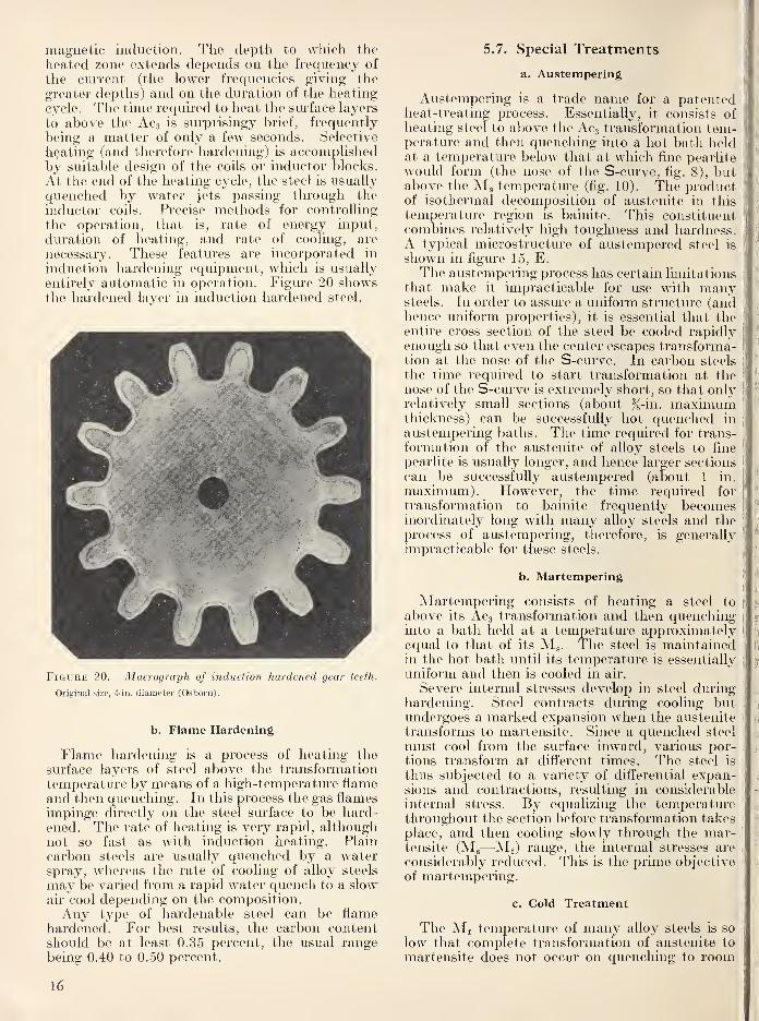
magnetic induction. The depth to which the
heated zone extends depends on the frequency of
the current (the lower frequencies giving the
greater depths) and on the duration of the heatingcycle. The time required to heat the surface layers
to above the Acg is surprisingy brief, frequently
being a matter of only a few seconds. Selective
heating (and therefore hardening) is accomplishedby suitable design of the coils or inductor blocks.
At the end of the heating cycle, the steel is usually
quenched by water jets passing through the
inductor coils. Precise methods for controlling
the operation, that is, rate of energy input,
duration of heating, and rate of cooling, are
necessary. These features are incorporated in
induction hardening equipment, which is usually
entirely automatic in operation. Figure 20 showsthe hardened layer in induction hardened steel.
Figure 20. Macrograph of induction hardened gear teeth.
Original size, 4-in. diameter (Osborn).
b. Flame Hardening
Flame hardening is a process of heating the
surface layers of steel above the transformationtemperature by means of a high-temperature flameand then quenching. In this process the gas flames
impinge directly on the steel surface to be hard-ened. The rate of heating is very rapid, althoughnot so fast as with induction heating. Plaincarbon steels are usually quenched by a waterspray, whereas the rate of cooling of alloy steels
may be varied from a rapid water quench to a slowair cool depending on the composition.Any type of hardenable steel can be flame
hardened. For best results, the carbon contentshould be at least 0.35 percent, the usual rangebeing 0.40 to 0.50 percent.
5.7. Special Treatments
a. Austempering
Austempering is a trade name for a patentedheat-treating process. Essentially, it consists ofheating steel to above the Acg transformation tem-perature and then quenching into a hot bath heldat a temperatm-e below that at which fine pearlite
would form (the nose of the S-curve, fi.g. 8), butabove the Mg temperature (fig. 10). The productof isothermal decomposition of austenite in this
temperature region is bainite. This constituentcombines relatively high toughness and hardness.A typical microstructure of austempered steel is
shown in figure 15, E.Tlie austempering process has certain limitations
that make it impracticable for use with manysteels. In order to assure a uniform structure (andhence uniform properties), it is essential that theentire cross section of the steel be cooled rapidlyenough so that even the center escapes transforma-tion at the nose of the S-curve. In carbon steels
the time required to start transformation at thenose of the S-curve is extremely short, so that onlyrelatively small sections (about %-in. maximumthickness) can be successfully hot quenched in
austempering baths. The time required for trans-
formation of the austenite of alloy steels to fine
pearlite is usually longer, and hence larger sections
can be successfully austempered (about 1 in.
maximum). However, the time required for
transformation to bainite frequently becomesinordinately long with many alloy steels and theprocess of austempering, therefore, is generallyimpracticable for these steels.
b. Martempering
Martempering consists of heating a steel to
above its Acs transformation and then quenchinginto a bath held at a temperature approximatelyequal to that of its Mg. The steel is maintainedin the hot bath until its temperature is essentially
uniform and then is cooled in air.
Severe internal stresses develop in steel duringhardening. Steel contracts during cooling butundergoes a marked expansion when the austenite
transforms to martensite. Since a quenched steel
must cool from the surface inward, various por-tions transform at different times. The steel is
thus subjected to a variety of differential expan-sions and contractions, resulting in considerableinternal stress. By equalizing the temperaturethroughout the section before transformation takes
place, and then cooling slowly through the mar- .]
tensite (M.,—-Mf) range, the internal stresses are i
considerably reduced. This is the prime objective
of martempering.
c. Cold Treatment
The Mj temperature of many alloy steels is so
low that complete transformation of austenite to
martensite does not occur on quenching to room
16
temperature or on cooling after tempering. Thisretained austenite may be partially or completelytransformed by cooling below atmospheric tem-peratm'es and such treatment is called "cold treat-
ment." The beneficial effects of cold treatmenthave not been fully explored. It is known that
the retained austenite of highly alloyed steels is
frequently difficult to transform. Cooling these
steels to low temperatm'es (to the temperature of
solid CO2 or even lower) immediately after the
quench is sometimes efi'ective in transforming the
retained austenite, but with the concomitant dan-ger of cracking. When the cold treatment is ap-
plied after tempering, the retained austenite is
considerably more resistant to transformation. If
cold treatment is used, the steel should always betempered afterwards.
Repeated alternate heating to a temperatm'eslightly below that used in tempering and cooling
to a subzero temperature in a refrigerated iced
brine, carbon dioxide, liquid air, or lic|uid nitrogenis commonly used for transforming the retainedaustenite (dimensional stabilization) of steel
gages, especially those of the ball-bearing typecomposition (AISI 52100).
6. Hardenability
Hardenability is the property that determinesthe depth and distribution of hardness induced in
steel by quenching. It is increased by increasing
carbon and by the addition of all the common alloy-
ing elements (except cobalt), provided that these
elements are completely dissolved in the austenite
at quenching temperatures. The elements mostfrequently used for this purpose are manganese,chromium, and molybdenum. Hardenability is
also enhanced by increased grain size^ and homo-geneity of the austenite. However, a coarse-
grained austenite increases the tendency of a steel
to distort and crack durmg heat treatment.Coarse-grained steels also are less tough than fine-
grained steels.
A clear distinction must be draum between themaximum hardness obtainable m a steel and its
hardenability. In straight carbon and low-alloysteels, the maximum hardness is a function of car-
bon content only (fig. 1.3), whereas hardenabilityis concerned primarily with the depth of hardening.Numerous methods have been proposed and
used for determining the hardenability of steel.
2 The grain size tliat influences hardenability is that grain size of theaustenite that exists at the quenching temperature. It is usually measuredunrler the microscope in terms of the number of grains per square inch at am;ignific;ition of XIOO. The common range of grain size numbers is asfollows (note that the larger the number, the finer is the grain size; i.e., themore grains there are per square inch):
Grain size no.(American Society for Grains/in.^Testing Materials) at XIOO
1 = H to m2 UA to 33 3 to 64 6 to 125 12 to 246 24 to 487 48 to 968 90 to 192
Numbers 3 and under are considered as coarse grain, numbers 4 and 5 asintermediate, and numbers 'j and higher as fine-grain steels.
The selection of a method depends largely uponthe information desired and the range in harden-ability of the steels.
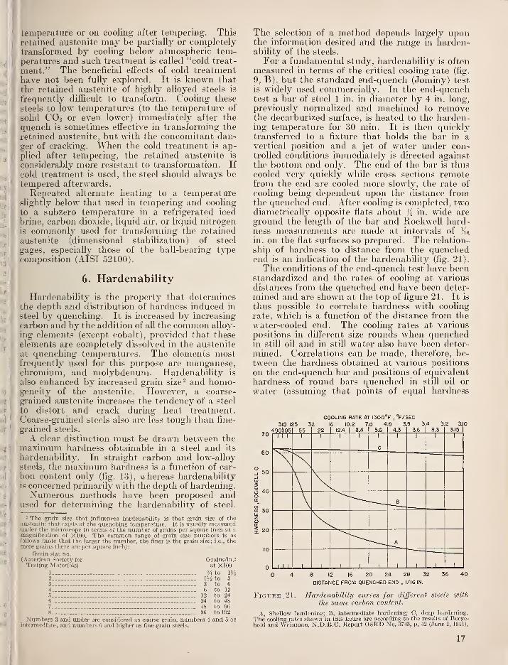
For a fundamental study, hardenability is oftenmeasured in terms of the critical cooling rate (fig.
9, B), but the standard end-quench (Joniiny) test
is widely used commercially. In the end-quenchtest a bar of steel 1 ui. in diameter by 4 in. long,
previously normalized and machined to removethe decarbm'ized surface, is heated to the harden-ing temperature for 30 min. It is then quicklytransferred to a fixture that holds the bar in avertical position and a jet of water under con-trolled conditions immediately is directed againstthe bottom end only. The end of the bar is thuscooled very quickly while cross sections remotefrom the end are cooled more slowly, the rate of
cooling being dependent upon the distance fromthe c^uenched end. After coolmg is completed, twodiametrically opposite flats about in. wide are
ground the length of the bar and Rockwell hard-ness measurements are made at intervals of Ke.
in. on the flat surfaces so prepared. The relation-
ship of hardness to distance from the ciuenchedend is an indication of the hardenability (fig. 21).
The conditions of the end-quench test have beenstandardized and the rates of cooling at variousdistances from the quenched end have been deter-
mined and are shown at the top of figure 21. It is
thus possible to correlate hardness with cooling
rate, which is a function of the distance from the
water-cooled end. The cooling rates at various
positions in different size rounds when quenchedin still oil and in still water also have been deter-
mined. Correlations can be made, therefore, be-
tween the hardness obtained at various positions
on the end-quench bar and positions of equivalenthardness of round bars quenched in still oil or
water (assuming that points of equal hardness
COOLING RATE AT I300°F , °F/SEC
310 125 32 16 10.2 7.0 4.8 3.9 3.4 3.2 3.10
60
10
490|l95 55'22 12.4 8.4 5.6 4.3 3.6 3.3 3.15
1 1 1 1 1 1 1 1
C
1 1 1 1
B
A
1 1 11
1
1 1 1 1 1 11
0 4 8 12 16 20 24 28 32 36 40
DISTANCE FROI«l QUENCHED END , 1/16 IN.
Figure ,21. Hardenability ctirves for different steels with
the same carbon content.
A, Shallow hardening; B, intermediate hardening; C, deep hardening.The cooling rates shown in this figure are according to the results of Boege-hold and Weinman, N.D.R.C. Report OSRD No. 3743, p. 42 (June 1, 1944).
17
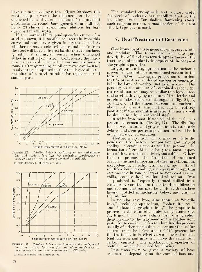
have the same coohng rate). Figui'e 22 shows this
relationship between the distances on the end-quenched bar and various locations for equivalenthardnesses in round bars quenched in still oil;
figiu"e 23 shows corresponding relations for barsquenched in still water.
If the hardenability (end-quench) curve of asteel is known, it is possible to ascertain from this
curve and the curves given in figures 22 and 23whether or not a selected size round made fromthe steel will have a desired hardness at its surface,
% radius, K radius, or center, when quenchedeither in still oil or water. Conversely, the hard-ness values as determined at various positions in
rounds after quenching in oil or water can be usedto advantage in approximating the degree of hard-enability of a steel suitable for replacement of
similar parts.
0 I— I \ \ 1 1 1 \ 1 1 1
0 2 4 6 8 10 12 14 16 18 20 22 24
DISTANCE FROM WATER QUENCHED END, I/I6IN.
FiGUEE 22. Relation between distances on the end-quenchbar and various locations for equivalent hardnesses or
cooling rates in ro\md bars quenched in still oil.
(Metals Handbook, 1948 edition, p. 492.)
<
SURFACE / 3/4ADIUS /}
^1/2WDIUS
J/XENTER
O 2 4 6 8 10 12 14 16 18 20
DISTANCE'FROM WATER QUENCHED END. 1/16 IN.
Figure 23. Relation between distances on the end-quenchbar and various locations for equivalent hardnesses orcooling rates in round bars quenched in still water.
(Metals Handbook, 1948 edition, p. 492.)
The standard end-quench test is most usefulfor steels of moderate hardenability, that is, thelow-alloy steels. For shallow hardening steels,
such as plain carbon, a modification of this test(the L-type bar) is used.
7. Heat Treatment of Cast Irons
Cast irons are of three general types, gray, white,and nodular. The terms gray and white are i
descriptive of the characteristic appearances of thefractures and nodular is descriptive of the shape ofthe graphite particles.
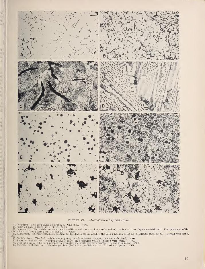
In gray iron a large proportion of the carbon is
present as graphitic or uncombined carbon m theform of flakes. The small proportion of carbonthat is present as combined carbon or cementite
I
is in the form of pearlite just as in a steel. De-pending on the amount of combined carbon, thematrix of cast iron may be similar to a hypoeutec-toid steel with varying amounts of free ferrite andgraphite flakes dispersed throughout (fig. 24, A,B, and C). If the amount of combined carbon is
about 0.8 percent, the matrix will be entirelypearlitic ; if the amount is greater, the matrix will
be similar to a hypereutectoid steel.
In white iron most, if not all, of the carbon is
present as cementite (fig. 24, D). The dividingline between white and gray cast iron is not clearly
defined and irons possessing characteristics of bothare called mottled cast iron.
Whether a cast iron will be gray or white de-pends on two factors—composition and rate ofcooling. Certain elements tend to promote theformation of graphitic carbon; the most impor-tant of these are silicon, nickel, and sulfur. Otherstend to promote the formation of combinedcarbon ; the most important of these are chromium,molybdenum, vanadium, and manganese. Rapidsolidification and cooling, such as result from thin
sections cast in sand or larger sections cast againstchills, promote the formation of white iron. Ironso produced is frequently termed chilled iron. ;
Because of variations in the rate of solidification i
and cooling, castings may be white at the surfacelayers, mottled immediately below, and gray in
the interior.
In nodular cast iron, also known as "ductile
iron," "nodular graphite iron," "spherulitic iron,"
and "spheroidal graphite iron," the graphite is
present in the form of nodules or spheroids (fig.
24, E and F). These nodules form during solid-
ification due to the treatment of the molten u'on,
just prior to casting, with a few hundredths percentusually of either magnesium or cerium ; the sulfur
I
content must be below about 0.015 percent for!
the treatment to be effective with these elements.
Nodular iron and gray iron have the same total
carbon content. The mechanical properties of
nodular iron can be varied by alloying.
Cast irons may be given a variety of heat '
treatments, depending on the compositions and
18
• ^ •
Figure 24. Microstructure of cast irons.
A, Gray iron. The dark flakes are graphite. XJnetched. XIOO.B, Same as (A). Etched with picral. XIOO.C, Same as fB). The matrix consists of pearlite with a small amount of free ferrite (white) and is similar to a hypoeuteetoid steel. The appearance of the
graphite flakes is not affected by the etchant. X500.
X50?'iron. The white needles are cemcntite; the dark areas are pearlite; the dark spheroidal areas are the eutectlc (Ledeburite). Etched with picral.
E, Nodular iron. The dark nodules are graphite; the white matrix is ferrite. Etched with picral. XIOO.F, Pearlitic nodular iron. Xodular graphite (dark) in a pearlitic matrix. Etched with picral. XIOO.G, Malleable iron. The dark nodules are graphite; the white matrix is ferrite. Etched with picral. XIOO.H, Pearlitic malleable iron. Nodular graphite (dark) in a pearlitic matrix. Etched with picral. XIOO.
19
desired properties. The principles of the heattreatments applied to cast iron are similar to thosealready discussed for steels.
7.1. Relieving Residual Stresses (Aging)
The heat treatment that relieves residual stressesis commonly called "aging," "normalizing," or"mild annealing;" the term "stress relieving" is
more accurately descriptive. This treatment canbe accomplished by heating the cast iron to be-tween 800° and 1,100° F, holding at temperaturefrom 30 min. to 5 hr, the time depending on thesize and temperature, and cooling slowly in thefurnace.
_Such treatment will cause only a slight
decrease in hardness, very little decomposition ofcementite, and only a slight change in the strengthof the metal.
7.2. Annealing
Sometimes it is desirable to soften castmgs inorder to facilitate machinmg. The temperaturerange most commonly used for this purpose is
1,400° to 1,500° F, although temperatures as lowas 1,200° to 1,250° F have been used satisfactorily.Highly alloyed irons are sometimes annealed attemperatures as high as 1,800° F. In all anneal-ing, care should be taken to prevent oxidation ofthe casting and coolmg should be slow.
In general, softenmg for machinability is ac-companied by a decrease in strength and in theamount of combined carbon, and by an increase ingraphite content. Irons that contain carbide-forming elements (such as chromium, molybde-num, vanadium, and manganese) are moreresistant to softening than the ordinary gray ironand, therefore, must be annealed at considerablyhigher temperatures. Completely annealed ordi-nary gray cast iron has a Brinell hardness of 120to 130, and completely annealed alloy irons mayhave a Brmell hardness of 130 to 180, dependingon the composition.The matrix of nodular iron can be made com-
pletely ferritic by heating at 1,300° F for 1 to5 hr, depending on composition, size of castmg,and amount of pearlite in the as-cast structure;cooling from the annealmg temperature can be atany convenient rate. If massive or primarycarbides are present m the as-cast structure, theymay be converted to spheroidal graphite byheating at 1,600° to 1,700° F for 1 to 5 hr.Slowly cooling from this temperature range to
about 1,275° F and holding from 3 to 5 hr will
convert the matrix to ferrite. Nodular iron witha ferritic matrix has the desirable combination ofmaximum machinability, toughness, and ductility.
The hardness of ferritic nodular iron varies withthe alloy content from a low of about 130 Brinellto a high of about 210 Brinell.
a. Malleabilizing
Malleabilizing (also termed graphitizing) is aprocess of annealing white cast iron m such a way
that the combined carbon is wholly or partly trans-formed to graphite in the nodular form (fig. 24,G and H) instead of the flaky form that exists in
gray cast iron. The nodular form of carbon is
called temper or free carbon. In some instances,part of the carbon is lost in the malleabilizingprocess.
White iron that is to be malleabilized shouldcontain all its carbon in the combined form. Anycarbon present as graphitic carbon (and hence in
the form of flakes) will not be affected by thegraphitizmg treatment and is undesirable in thefinal structure.
The temperatures used in malleabilizing usuallyrange from about 1 ,500° to 1 ,650° F. Time at tem-perature is quite long, frequently being as muchas two to three days. Holdmg at this temperaturecauses the decomposition of the cementite intoaustenite plus rather rounded forms of graphite.If the iron is then cooled very slowly through thecritical range (less than 10° F/hr), the resultantstructure will consist of ferrite plus temper carbon.Cooling less slowly through the transformationrange, or using an iron containing an alloyingelement that retards graphitization, results in afinal product containing various amounts of pearl-
ite plus ferrite with, of course, temper carbon.Irons having a pearlitic structure plus temper car-
bon are known as pearlitic malleable irons (fig. 24,
H). As might be expected, pearlitic malleableirons are susceptible to heat treatment in the samemanner as steels.
7.3. Normalizing, Quenching, and Tempering
When heated to above the critical temperature(line SK, fig. 3), cast iron consists of austeniteplus excess cementite or graphite and the austenitecan be transformed in the same manner as in
steel. Although irons that are almost completelygraphitic (the common soft gray irons) can behardened, this is not customary. Such irons mustbe held at temperatures well above the critical for
long periods of tune in order to assure the solution
of carbon in the austenite.
For optimum results, the graphite flakes shouldbe small and uniformly distributed and the matrixshould be peaiiitic with not too much free ferrite
(combined carbon from about 0.50 to 0.80%).Castings should be heated uniformly to the quench-mg temperature, which usually ranges from 1,500°
to 1,600° F. The quenching medium commonlyused is oil; water is used to a limited extent andsome alloy castings may be quenched in air. Theiron, as quenched, generally has a lower strengththan as cast, but the strength is increased bytempering in the range of 350° to 1,200° F.
Softening proceeds uniformly as the temperingtemperature is mcreased above about 350° to
1,200° F.
A pearlitic matrix can be produced in nodulariron as cast or by normalizing. The normalizingtreatment consists of heating to 1,600° to 1,650° F
20
holding at temperature for solution of carbon,
followed by cooling in air. The mechanicalproperties of the normalized irons vary with the
composition, fineness, and amoimts of pearlite;
heavy sections are lower m hardness and higher
in ductility than light sections. The Brinell
hardness numbers range from about 200 to 275.
Martensitic or bainitic structures are producedin nodular iron by quenching from 1,600° to
1,700° F m oil or water. The kons as quenchedhave high strengths but low ductility. However,the ductility of the as-quenched u'on can bematerially increased (strength and hardness de-
creased) by tempermg at about 1,000° to 1,300° F.
7.4. Special Heat Treatments
Subject to the same limitations as steels, cast
irons can be flame-hardened, mduction-hardened,austempered, martempered, or nitrided.
8. Practical Considerations
Satisfactory heat treatment of steel (and iron)
requires fmnaces that have uniform controlled
temperatm'es, means for accm-ate temperatm^emeasurement, and for protecting the surface of thematerial from scaling or decarburizing. Properquenching equipment is needed also.
8.1. Furnaces and Salt Baths
There are many different types and sizes of
furnaces used in heat treatment. As a generalrule, furnaces are designed to operate in certainspecific temperature ranges and attempted use in
other ranges frequently results in work of inferior
quality. In addition, using a furnace beyond its
rated maximum temperature shortens its life andmay necessitate costly and time-consummg repau's.
Fuel-fired furnaces (gas or oil) recj[uire an- for
proper combustion and an air compressor orblower is therefore a necessary adjunct. Thesefurnaces are usually of the muffle type, that is, thecombustion of the fuel takes place outside of andaround the chamber in which the work is placed.If an open muffle is used, the furnace should bedesigned so as to prevent the duect impingementof flame on the work.
In furnaces heated by electricity the heatingelements are generally in the form of wire orribbon. Good design requires incorporation ofadditional heating elements at locations wheremaximum heat loss may be expected. Suchfurnaces commonly operate up to a maximumtemperature of about 2,000° F. Fm-naces oper-ating at temperatures up to about 2,500° F usuallyemploy resistor bars of sintered carbides.
Furnaces intended primarily for tempering maybe heated by gas or electricity and are frequentlyequipped with a fan for cuculating the hot air.
Salt baths are available for operating at either
tempering or hardening temperatures. Depend-ing on the composition of the salt bath, heatingcan be conducted at temperatures as low as 325° Fto as high as 2,450° F. Lead baths can be used in
the temperature range of 650° to 1,700° F. Therate of heating in lead or salt baths is much faster
than in fm-naces.
a. Protective Atmospheres
It is often necessary or desirable to protect steel
or cast ii'on from surface oxidation (scaling) andloss of carbon from the surface layers (decarburi-
zation, fig. 15, F) . Commercial furnaces, therefore,
are generally equipped with some means of
atmosphere control. This usually is in the formof a bm'ner for burning controlled amounts of gasand au" and directing the products of combustioninto the fmiiace muffle. Water vapor, a product of
this combustion, is detrunental and many furnacesare equipped with a means for eliminating it. Forfurnaces not equipped with atmosphere control, avariety of external atmosphere generators are
available. The gas so generated is piped into thefurnace and one generator may supply several
fm-naces. If no method of atmosphere control is
available, some degree of protection may besecured by covering the work with cast u-on
borings or chips.
Since the work in salt or lead baths is surroundedby the liquid heating medium, the problem of
preventing scaling or decarburization is simplified.
b. Temperature Measurement and Control
Accm-ate temperature measurement is essential
to good heat treating. The usual method is bymeans of thermocouples; the most common base-metal couples are copper-Constantan (up to about700° F), iron-Constantan (up to about 1,400° F),
and Chromel-Alumel (up to about 2,200° F).
The most common noble-metal couples (which canbe used up to about 2,800° F) are platinumcoupled with either the alloy 87 percent platinum—13 percent rhodium or the alloy 90 percentplatinum—^10 percent rhodium. The tempera-tures quoted are for continuous operation.
The life of thermocouples is afl'ected by the
maximum temperature (which may frequently
exceed those given above) and by the furnaceatmosphere. Iron-Constantan is more suited for
use in reducing and Chromel-Alumel in oxidizing
atmospheres. Thermocouples are usually encasedin metallic or ceramic tubes closed at the hot endto protect them from the furnace gases. Anecessary adjunct is an instrument, such as a
millivoltmeter or potentiometer, for measuring the
electromotive force generated by the thermocouple.In the interest of accurate control, the hotjunction of the thermocouple should be placed as
close to the work as possible. The use of anautomatic controller is valuable in controlling the
temperature at the desired value.
21
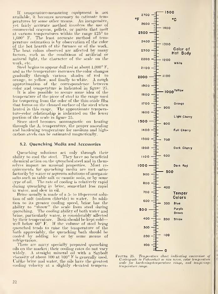
If temperature-measuring equipment is not
available, it becomes necessary to estimate tem-peratures by some other means. An inexpensive,
yet fairly accurate method involves the use of
commercial crayons, pellets, or paints that meltat various temperatures witlain the range 125° to
1,600° F. The least accurate method of tem-perature estimation is by observation of the color
of the hot hearth of the furnace or of the work.The heat colors observed are affected by manyfactors, such as the conditions of artificial or
natural light, the character of the scale on the
work, etc.
Steel begins to appear dull red at about 1,000° F,
and as the temperature increases the color changesgradually through various shades of red to
orange, to yellow, and finally to white. A roughapproximation of the correspondence betweencolor and temperature is indicated in figure 25.
It is also possible to secure some idea of the
temperature of the piece of steel in the range usedfor tempering from the color of the thin oxide film
that forms on the cleaned surface of the steel whenheated in this range. The approximate tempera-ture-color relationship is indicated on the lowerportion of the scale in figure 25.
Since steel becomes nonmagnetic on heatingthrough the A2 temperature, the proper annealingand hardening temperature for medium and high-
carbon steels can be estimated magnetically.
8.2. Quenching Media and Accessories
Quenching solutions act only through their
ability to cool the steel. They have no beneficial
chemical action on the quenched steel and in them-selves impart no unusual properties. Most re-
quirements for quenching media are met satis-
factorily by water or aqueous solutions of inorganicsalts such as table salt or caustic soda, or by sometype of oil. The rate of cooling is relatively rapidduring quenching in brine, somewhat less rapidin water, and slow in oil.
Brine usually is made of a 5- to 10-percent solu-
tion of salt (sodium chloride) in water. In addi-tion to its greater cooling speed, brine has the
ability to "throw" the scale from steel duringquenching. The cooling ability of both water andbrine, particularly water, is considerably affected
by their temperature. Both should be kept cold
—
well below 60° F. If the volume of steel beingquenched tends to raise the temperature of thebath appreciably, the quenching bath should becooled by adding ice or by some means of
refrigeration.
There are many specially prepared quenchingoils on the market; their cooling rates do not varywidely. A straight mineral oil with a Sayboltviscosity of about 100 at 100° F is generally used.Unlilce brine and water, the oils have the greatestcooling velocity at a slightly elevated tempera-
2700
2600Z 1400
2500
2400 1
2300
2200
2 100
2000 -
1900
1800
1700
1600
1500 -
1400
1300
1200
1100
100 0 -
900
800
700
600
50 0 -
1500
•c
— 1300
Color ofHot Body
1200
1 100
1000
White
Yellow
900
800
— 700
— 600
Orange
Light Cherry
Full Cherry
Dork Cherry
Dark Red
500
400
TemperColors
300 Blue
Purple
Brown
200 Strow
100
400
300
200
100
Figure 25. Temperature chart indicating conversion ofCentrigrade to Fahrenheit or vice versa, color temperaturescale for hardening-temperature range, and tempering-temperature range.
22
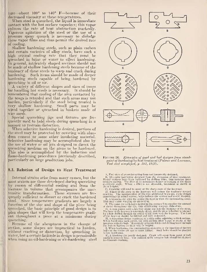
tui-e—about 100° to 140° F—because of their
decreased viscosity at these temperatures.Wlien steel is quenched, the liquid in immediate
contact with the hot surface vaporizes; this vaporreduces the rate of heat abstraction markedly.Vigorous agitation of the steel or the use of apressure spray c^uench is necessary to dislodge
these vapor films and thus permit the desired rate
of coohng.Shallow hardeiiing steels, such as plain carbon
and certain varieties of alloy steels, have such ahigh critical coohng rate that they must bequenched in brine or water to effect hardening.In general, intricately shaped sections should notbe made of shallow liardening steels because of the
tendency of these steels to warp and crack duringhardening. Such items should be made of deeperhardening steels capable of being hardened byquenching in oU or air.
A variety of different shapes and sizes of tongsfor handling hot steels is necessary. It should beremembered that cooling of the area contacted bythe tongs is retarded and that such areas may notharden, particularly if the steel being treated is
very shallow hardening. Small parts may bewired together or quenched in baskets made ofwire mesh.
Special quenching jigs and fixtures are fre-
quently used to hold steels during quenching in amanner to restrain distortion.
When selective hardening is desired, portions ofthe steel may be protected by covering with alun-dum cement or some other insulating material.Selective hardening may be accomplished also bythe use of water or oil jets designed to direct thequenching medium on the areas to be hardened.This also is accomplished by the induction andflame-hardening procedures previously described,particularly on large production jobs.
8.3. Relation of Design to Heat Treatment
Internal strains arise from many causes, but themost serious are those developed cluring quenchingby reason of differential cooling and from theincrease in volume that accompanies the mar-tensitic transformation. These stresses are fre-
quently sufficient to distort or crack the hardenedsteel. Since temperature gradients are largely a
III function of the size and shape of the piece beingquenched, the basic principle of good design is to
plan shapes that will keep the temperature gradi-ent throughout a piece at a minimum during
j
quenching.Because of the abruptness in the change of
section, some shapes are impractical to harden,without cracking or distortion, by quenching in
water, but a certain latitude in design is permissiblewhen using an oil-hardening or air-hardening steel
J K
Figure 26. Examples of good and bad designs from stand-point of hardening by heat treatment {Palmer and Luerssen,Tool steel simplified, p. 392, 1948).
A, End view of an undercutting form tool incorrectly designed.
B, The same tool better designed from the viewpoint of heat treatment.Heavy sections have been lightened by drilling holes, thus insuring moreuniform cooling. The fillet at (a) minimizes danger of cracking at the sharpre-entrant angle. Where a fillet is not allowable, treatment as shown at
(b) is helpful.
C, Cracking will tend to occur at the sharp roots of the keyways.D, Fillets at the roots of the keyways will reduce the tendency toward
cracking. The incorporation of the two additional keyways, even thoughuimecessary in actual service, helps balance the section and avoid warping.
E, A blanking die with the center rib heavier than the surrounding areas.
This may cause warping on quenching.
F, The same die with holes drilled in the center rib to equaUze the amountof metal throughout the die, thus eliminating warpage difficulties.
G, A stem pinion with a keyway about one-half the diameter of the stem.
The base of the keyway is extremely sharp, and the piece is further weakenedby a hole drilled through the center of the stem near the keyway. The base
of the keyway should be filleted and hole re-located.
H, A dangerous design consisting of a thin collar adjoining a thick section.
When hardening such pieces, the thin section often warps or cracks at the
junction with the hub. Extremely generous fillets and diiUing holes throughthe hub to lighten its mass will be helpful.
J, When hardening, the concentration of strains at the junction of the twoholes in the center are apt to cause failure. Such holes should be plugged
before hardening.K, A blanking die poorly desig-ned. Crack will occur from point of fork
prong to setscrew hole. The position of the setscrew hole should be changedto eliminate cracking.
23
Other things being equal, temperature gradientsare much lower in shapes quenched in oil than in
water, and are still less in air. Thus a certain
design may be perfectly safe for one type of steel,
or one type of coolant, and unsafe for another.
Errors in design reach farther than merelyaffecting the internal strains during hardening.A sharp angle or notch serves to greatly concen-trate the stresses applied during service, and thedesign of the part may be entirely responsible for
concentrating the service stresses at a pointaheady weakened by internal strains producedduring hardening. Concentration of ser\^ice
stresses frequently parallels coilcentration of heat-
treating strains and is frequently caused and cm'edby the same combination of chcumstances.A part is properly designed, from a standpoint
of heat treatment, if the entire piece can be heatedand cooled at approximately the same rate dm-ingthe heat-treating operations. Perfection in this
regard is unattainable because, even in a sphere,
the surface cools more rapidly than the interior.
The designer should, however, attempt to shapeparts so that they will heat and cool as uniformlyas possible. The greater the temperatm^e differ-
ence between any two points in a given part duringquenching, and the closer these two points are
together, the greater will be the internal strain
and, therefore, the poorer the design.
When large and small sections are unavoidablein the same piece, the thick part frequently can belightened by drilling holes through it. Wherechanges in section are eiicountered, angles shouldbe filletted generously. Some examples of poorand good design are shown in figure 26.
9. Nomenclature and ChemicalCompositions of Steels
9.1. Structural Steels
In order to facilitate the discussion of steels,
some familiarity with their nomenclature is de-
sirable.
A numerical index, sponsored by the Society of
Automotive Engineers (SAE) and the AmericanIron and Steel Institute (AISI), is used to identify
the chemical compositions of the structural steels.
In this system, a four-numeral series is used to
designate the plain carbon and alloy steels; five
numerals are used to designate certain types of
alloy steels. The first two digits indicate the
type of steel, the second digit also generally (butnot always) gives the approximate amount of themajor alloying element and the last two (or tliree)
digits are intended to indicate the approximatemiddle of the carbon range. However, a devia-tion from the rule of indicatmg the carbon rangeis sometimes necessary.
The series designation and types are summarizedas follows:
Series
designation Types
lOxx Nonsulphurized carbon steels
llxx Resulphuri-zed carbon steels (free machining)12xx Rephosphorized and resulphurized carbon
steels (free machining)13xx Manganese 1.75%*23xx Nickel 3.50 %*25xx Nickel 5.00%31xx Nickel 1.25%, chromium 0.65%33xx Nickel 3.50%, chromium 1.55%40xx Molybdenum 0.20 or 0.25%41xx Chromium 0.50 or 0.95%, molybdenum 0.12
or 0.20%43xx Nickel 1.80%, chromium 0.50 or 0.80%,
molybdenum 0.25%44xx Molybdenum 0.40%45xx Molybdenum 0.52%.46xx Nickel 1.80%, molybdenum 0.25%47xx Nickel 1.05%, chromium 0.45%, molybde-
num 0.20 or 0.35%48xx Nickel 3.50%, molybdenum 0.25%50xx Chromium 0.25, 0.40 or 0.50%50xxx Carbon 1.00%, chromium 0.50%51xx Chromium 0.80, 0.90, 0.95, or 1.00 %o51xxx Carbon 1.00%, chromium 1.05%52xxx Carbon 1.00%, chromium 1.45%61xx Chromium 0.60, 0.80 or 0.95%, vanadium
0.12%, 0.10% min., or 0.15% min.81xx Nickel 0.30%, chromium 0.40%, molyb-
denum 0.12%86xx Nickel 0.55%, chromium 0.50%, molyb-
denum 0.20%87xx Nickel 0.55%, chromium 0.50%, molyb-
denum 0.25%88xx Nickel 0.55 %o, chromium 0.50%, molyb-
denum 0.35%92xx Manganese 0.85%, silicon 2.00%, chromium
Oor 0.35%93xx Nickel 3.25%, chromium 1.20%, molyb-
denum 0.12%94xx Nickel 0.45%, chromium 0.40%, molyb-
denum 0.12%98xx Nickel 1.00%, chromium 0.80%, molyb-
denum 0.25%Not included in the current list of standard steels.
Listings of the SAE-AISI type numbers andchemical composition limits of the standard andtentative standard structural steels (complete as I
of February 1960) are given in table 1. The SAE i'
numbers are the same as the AISI numbers, exceptthat the latter may be given a letter prefix to in-
dicate the method of manufacture. These pre-
fixes and their meanings are as follows: B denotesacid bessemer carbon steel, C denotes basic openhearth or basic electric furnace carbon steels, Edenotes electric furnace alloy steels.
Small quantities of certain elements are presentin alloy steels that are not specified as required.
These elements are considered as incidental andmay be present to the maximum amounts as I'
follows: copper, 0.35 percent; nickel, 0.25 percent;
chromium, 0.20 percent; molybdenum, 0.06 per-
cent.
24
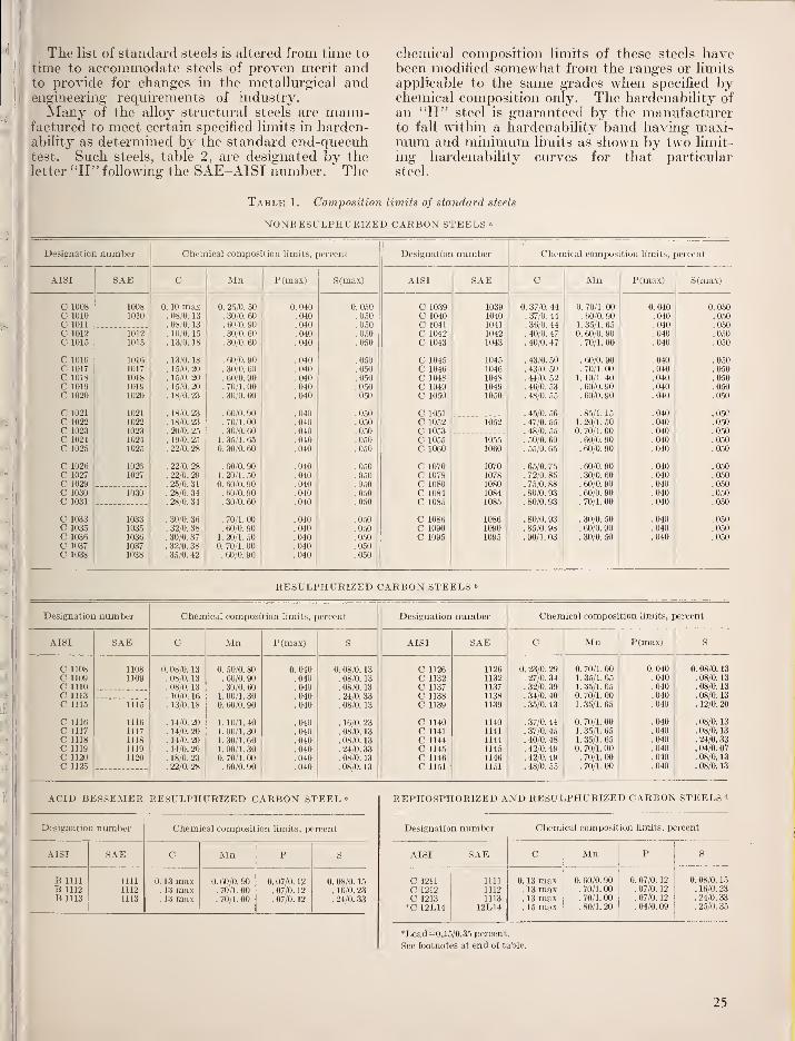
The list of standard steels is altered from time to
time to accommodate steels of proven merit andto provide for changes in the metallm-gical andengineering requirements of industry.
Alany of the alloy structm-al steels are manu-factm'ed to meet certain specified limits in harden-ability as determmed by the standard end-quecnhtest. Such steels, table 2, are designated by the
letter "H" following the SAE-AISI number. The
chemical composition limits of these steels havebeen modified somewhat from the ranges or limits
applicable to the same grades when specified bychemical composition only. The hardenability of
an "H" steel is guaranteed by the manufacturerto fall within a hardenability band having maxi-mum and minimum limits as shown by two limit-
ing hardenability curves for that particularsteel.
Table 1. Composition limits of standard steels
NONEESULPHURIZED CARBON STEELS "
Designation number Chemical composition limits, percent Designation number Chemical composition limits, percent
AISI SAE C Mn P(max) S(max) AISI SAE C Mn P(max) S(max)
C 1008 1008 0. 10 max 0. 25/0. 50 0.040 0. 050 C 1039 1039 0. 37/0. 44 0. 70/1.00 0.040 0. 0.50
C 1010 1010 .08/0.13 . 30/0. 60 .040 .050 C 1040 1040 . 37/0. 44 . 60/0. 90 .040 .050C 1011 . 08/0. 13 . 60'0. 90 .040 .050 C 1041 1041 . 36/0. 44 1. 35/1. 65 .040 .050C 1012 1012 . 10/0. 15 . 30/0. 60 .040 .050 C 1042 1042 . 40/0. 47 0. 60/0. 90 .040 .050C 1015 1015 . 13/0. 18 . 30/0. 60 .040 .050 C 1043 1043 . 40/0. 47 . 70/1. 00 .040 .050
C 1016 1016 . 13/0. 18 . 60/0. 90 .040 .050 C 1045 1045 . 43/0. 50 . 60/0. 90 .040 .050C 1017 1017 . 15/0. 20 . 30/0. 60 .040 .050 C 1046 1046 . 43/0. 50 . 70/1. 00 .040 .050C 1018 1018 . 15/0. 20 . 60/0. 90 .040 .050 C 1048 1048 . 44/0. 52 ]. 10/1.40 .040 .050C 1019 1019 . 15/0. 20 . 70/1. 00 .040 .050 C 1049 1049 . 46/0. 53 . fiO/0. 90 .040 .050C 1020 1020 . 18/0. 23 . 30/0. 60 .040 .050 C 1050 1050 . 48/0. 55 . 60/0. 90 .040 .050
C 1021 1021 . 18/0. 23 . 60/0. 90 .040 .050 C 1051 . 45/0. 56 . 85/1. 15 .040 .050C 1022 1022 . 18/0. 23 .70/1.00 .040 .050 C 1052 1052"
. 47/0. 55 1. 20/1. 50 .040 .050C 1023 1023 . 20/0. 25 . 30/0. 60 .040 .050 C 1053 . 48/0. 55 0. 70/1. 00 .040 .050C 1024 1024 . 19/0. 25 1. 35/1. 65 .040 .050 C 1055 1055 . 50/0. 60 . 60/0. 90 .040 .050C 1025 1025 . 22/0. 28 0. 30/0. 60 .040 .050 C 1060 1060 . 56/0, 65 . 60/0. 90 .040 .050
C 1026 1026 . 22/0. 28 . 60/0. 90 .040 .050 C 1070 1070 . 65/0. 75 . 60/0. 90 .040 .050C 1027 1027 . 22/0. 29 1. 20/1. 50 .040 .050 C 1078 1078 . 72/0. 85 . 30/0. 60 .040 .050C 1029 . 25/0. 31 0. 60/0. 90 .040 .050 C 1080 1080 . 75/0. 88 . 60/0. 90 .040 .060C 1030 1030 . 28/0. 34 . 60/0. 90 .040 .050 C 1084 1084 . 80/0. 93 . 60/0. 90 .040 .050C 1031 . 28/0. 34 . 30/0. 60 .040 .050 C 1085 1085 . 80/0. 93 . 70/1. 00 .040 .060
C 1033 1033 . 30/0. 36 . 70/1. 00 .040 .050 C 1086 1086 . 80/0. 93 . 30/0. 50 .040 .060C 1035 1035 . 32/0. 38 . 60/0. 90 .040 .050 C 1090 1090 . 85/0. 98 . 60/0. 90 .040 .060C 1036 1036 . 30/0. 37 1. 20/1. 50 .040 .050 C 1095 1095 . 90/1. 03 . 30/0. 50 .040 .060C 1037 1037 . 32/0. 38 0. 70/1. 00 .040 .050C 1038 1038 . 35/0. 42 . 60/0. 90 .040 .050
RESULPHURIZED CARBON STEELS b
Designation number Chemical composition limits, percent Designation number Chemical composition limits, percent
AISI SAE C Mn P(max) S AISI SAE C Mn P(ma.\) s
C 1108 1108 0. 08/0. 13 0. 50/0. 80 0. 040 0. 08/0. 13 C 1126 1126 0. 23/0. 29 0. 70/1. 00 0. 040 0. 08/0. 13
C 1109 1109 . 08/0. 13 . 60/0. 90 .040 . 08/0. 13 C 1132 1132 . 27/0. 34 1. 35/1. 65 .040 . 08/0. 13
C 1110 . 08/0. 13 . 30/0. 60 .040 . 08/0. 13 C 1137 1137 . 32/0. 39 1.35/1.66 .040 . 08/0. 13
C 1113 . 10/0. 16 1.00/1.30 .040 . 24/0. 33 C 1138 1138 . 34/0. 40 0. 70/1. 00 .040 . 08/0. 13
C 1115 1115 . 13/0. 18 0. 60/0. 90 .040 . 08/0. 13 C 1139 1139 . 35/0. 43 1.35/1.65 .040 . 12/0. 20
C 1116 1116 . 14/0. 20 1. 10/1.40 .040 . 16/0. 23 C 1140 1140 . 37/0. 44 0. 70/1. 00 .040 . 08/0. 13
C 1117 1117 . 14/0. 20 1.00/1.30 .040 . 08/0. 13 C 1141 1141 . 37/0. 45 1.35/1.66 .040 . 08/0. 13
C 1118 1118 . 14/0. 20 1.30/1.60 .040 . 08/0. 13 C 1144 1144 . 40/0. 48 1.36/1.66 .040 . 24/0. 33
C 1119 1119 . 14/0. 20 1.00/1.30 .040 .24/0. 33 C 1146 1145 . 42/0. 49 0. 70/1. 00 .040 . 04/0. 07
C 1120 1120 . 18/0. 23 0. 70/1. 00 .040 . 08/0. 13 C 1146 1146 . 42/0. 49 . 70/1. 00 .040 . 08/0. 13
C 1125 . 22/0. 28 . 60/0. 90 .040 . 08/0. 13 C 1151 1151 . 48/0. 65 . 70/1. 00 .040 . 08/0. 13
ACID BESSEMER RESULPHURIZED CARBON STEEL"
Designation number Chemical composition limits, percent
AISI SAE C Mn P S
B nil nil 0. 13 max 0. 60/0. 90 0. 07/0. 12 0. 08/0. 16B 1112 1112 . 13 max . 70/1. 00 . 07/0. 12 . 16/0. 23B 1113 1113 . 13 max . 70/1. 00 . 07/0. 12 . 24/0. 33
REPHOSPHORIZED AND RESULPHURIZED CARBON STEELS ^
Designation numljer Chemical composition limits, percent
AISI SAE C Mn P S
C 1211 nil 0. 13 max 0. 60/0. 90 0. 07/0. 12 0. 08/0. 15
C 1212 1112 .13 max . 70/1. 00 . 07/0. 12 . 16/0. 23
C 1213 1113 . 13 max . 70/1. 00 . 07/0. 12 . 24/0. 33
*C 12L14 12L14 . 16 max .80/1.20 . 04/0. 09 . 25/0. 35
*Lead=0J.5/0.35 percent.
See footnotes at end ol table.
il
25
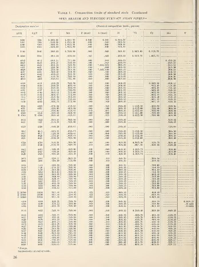
Table 1. Composition limits of standard steels—Continued
OPEN HEARTH AND ELECTRIC FURNACE ALLOY STEELS »
Designation number Chemical composition limits, percent
AISI SAE C Mn P (max) S (max) Si
1330 1330 0. 28/0. 33 1.60/1 90 0. 040 0. 040 0. 20/0. 35
1335 1335 . 33/0. 38 1. 60/1. 90 .040 .040 . 20/0. 35
1340 1340 . 38/0. 43 1. 60/1. 90 .040 .040 . 20/0. 35
1345 1345 . 43/0. 48 1. 60/1. 90 .040 .040 . 20/0. 35
3140 3140 . 38/0. 43 0. 70/0. 90 . 040 . 040 . 20/0. 35
E 3310 3310 . 08/0. 13 . 45/0. 60 .026 .026 . 20/0. 35
4012 4012 . 09/0. 14 . 75/1. 00 .040 .040 . 20/0. 36
4023 4023 . 20/0. 25 . 70/0. 90 .040 .040 . 20/0. 35
4024 4024 . 20/0. 25 . 70/0. 90 . 040 *. 036/. 050 . 20/0. 35
4027 4027 . 25/0. 30 . 70/0. 90 .040 .040 , 20/0. 35
4028 4028 . 25/0. 30 . 70/0. 90 .040 *. 035/. 050 . 20/0. 35
4037 4037 . 35/0. 40
'
. 70/0. 90 . 040 .040 . 20/0. 35
4042 4042 . 40/0. 45 . 70/0. 90 . 040 . 040 . 20/0. 35
4047 4047 '. 45/o! 50 ] 70/0. 90 .040 !040 '.
20/0. 36
4063 4063 . 60/0. 67 . 75/1. 00 .040 .040 . 20/0. 35
4118 4118 . 18/0. 23 . 70/0. 90 .040 .040 . 20/0. 35
4130 4130 . 28/0. 33 . 40/0. 60 .040 .040 . 20/0. 35
4135 4135 . 33/0. 38 . 70/0. 90 . 040 040 20/0. 36
4137 4137 '. 35/o! 40 '. 70/0. 90 .040 .040 '.
20/0. 35
4140 4140 . 38/0. 43 .75/1.00 .040 .040 . 20/0. 35
4142 4142 .40/0.45 . 75/1.00 . 040 . 040 20/0. 35
4145 4145 '. 43/o! 48 '. 76/1. 00 .040 .040 '. 20/0. 354147 4147 . 45/0. 50 76/1 00 . 040 . 040 . 20/0. 35
4150 4150 '. 4810. 53 '. 75/L 00 !040 !040 '. 20/o! 35
4320 4320 . 17/0. 22 . 45/0. 65 .040 .040 . 20/0. 35
4337 4337 . 35/0. 40 . 60/0. 80 .040 .040 . 20/0. 35
E 4337 . 35/0. 40 . 65/0. 85 . 025 . 025 . 20/0. 35
4340 4340 '. 38/o! 43 ! 60/o! 80 !040 .'040 '.
20/o'. 35
E 4340 E 4340 . 38/0. 43 . 65/0. 85 .026 .025 . 20/0. 35
4422 4422 . 20/0. 25 . 70/0. 90 .040 .040 . 20/0. 36
4427 4427 . 24/0. 29 . 70/0. 90 .040 .040 . 20/0. 35
4520 4520 . 18/0. 23 . 45/0. 65 . 040 . 040 20/0. 36
4615 4615 . 13/0. 18 .46/0. 65 .040 .040 . 20/0. 35
4617 4617 . lU/U. . 45/0. 65 . 040 . 040 90/0 3'i
4620 4620 . 17/0. 22 '. 45/o! 66 !040 !040 . 20/0. 364621 4621 . 18/0. 23 . 70/0. 90 .040 .040 . 20/0. 35
4718 4718 . 16/0. 21 . 70/0. 90 .040 .040 . 20/0. 354720 4720 . 17/0. 22 . 50/0. 70 .040 .040 . 20/0. 36
4815 4816 . 13/0. 18 . 40/0. 60 .040 .040 . 20/0. 354817 4817 . 16/0. 20 . 40/0. 60 .040 .040 . 20/0. 364820 4820 . 18/0. 23 . 50/0. 70 .040 .040 . 20/0. 36
5015 6015 . 12/0. 17 . 30/0. 50 .040 .040 . 20/0. 355046 5046 . 76/1. 00 . 040 . 040 90/0 ^5
. ZU/U. oo
5115 5116 .13/0.18 . 70/0. 90 .040 .040 . 20/0. 355120 5120 .17/0.22 . 70/0. 90 .040 .040 . 20/0. 355130 5130 9S/n
. ^o/u. oo 70/0 QO , 040 . 040 on/A
5132 6132 . 30/0. 35 . 60/0. 80 !040 ]040 . 20/0. 355135 5135 . 33/0. 38 . 60/0. 80 .040 .040 . 20/0. 355140 5140 . 38/0. 43 . 70/0. 90 .040 .040 . 20/0. 355145 5145 . 43/0. 48 . 70/0. 90 . 040 040 90/0
. ^u/u. oo5147 5147 '. 46/o! 52 '. 70/0. 95 !040 !040 . 20/0. 35
5150 70/0 QO . 040 040 9n /n ^. zu/u. oo
5165 5156 . 60/0. 60 . 70/0. 90 !040 ]040 . 20/0. 355160 5160 . 65/0. 65 .75/1.00 .040 .040 . 20/0. 35
E 50100 50100 . 96/1. 10 . 25/0. 45 .025 .025 . 20/0. 35E 51100 61100 . 96/1. 10 . 25/0. 45 .026 .025 . 20/0. 35E 52100 62100 . 96/1. 10 . 26/0. 46 .026 .025 . 20/0. 35
6118 6118 . 16/0. 21 . 50/0. 70 .040 .040 . 20/0. 366120 6120 . 17/0. 22 . 70/0. 90 .040 .040 . 20/0. 366150 6150 . 48/0. 63 . 70/0. 90 .040 .040 . 20/0. 36
8115 8116 . 13/0. 18 . 70/0. 90 .040 .040 . 20/0. 36
8615 8616 . 13/0. 18 . 70/0. 90 .040 .040 . 20/0. 368617 8617 . 15/0. 20 . 70/0. 90 .040 .040 . 20/0. 358620 8620 . 18/0. 23 . 70/0. 90 .040 .040 . 20/0. 358622 8622 . 20/0. 25 . 70/0. 90 .040 .040 . 20/0. 358625 8625 . 23/0. 28 . 70/0. 90 .040 .040 . 20/0. 368627 8627 . 2.5/0. 30 . 70/0. 90 .040 .040 . 20/0. 368630 8630 . 28/0. 33 . 70/0. 90 .040 .040 . 20/0. 358637 8637 . 36/0. 40 . 75/1. 00 .040 .040 . 20/0. 358640 8640 . 38/0. 43 .75/1.00 .040 .040 . 20/0. 358642 8642 . 40/0. 45 .75/1.00 .040 .040 . 20/0. 368645 8646 . 43/0. 48 . 75/1. 00 .040 .040 . 20/0. 358660 8660 . 48/0. 53 . 75/1. 00 .040 .040 . 20/0. 358656 8665 . 50/0. 60 . 75/1. 00 .040 .040 . 20/0. 358660 8660 . 55/0. 65 .75/1.00. .040 .040 . 20/0. 35
Ni Cr Mo
1. 10/1. 40
3. 25/3. 76
1. 66/2. 001. 66/2. 001. 65/2. 001. 66/2. 001. 65/2. 00
1. 65/2. 001. 6.5/2. 001. 65/2. 001. 65/2. 00
0. 90/1. 20. 90/1. 20
3. 26/3. 763. 25/3. 753. 25/3. 75
0. 20/0. 40
. 40/0. 70
. 40/0. 70
. 40/0. 70
. 40/0. 70
. 40/0. 70
. 40/0. 70
. 40/0. 70
. 40/0. 70
. 40/0. 70
. 40/0. 70
. 40/0. 70
. 40/0. 70
. 40/0. 70
. 40/0. 70
0. 55/0. 75
1. 40/1. 75
0. 40/0. 60. 80/1. 10
. 80/1. 10
. 80/1. 10
. 80/1. 00
. 80/1. 10
. 80/1. 10
. 80/1. 10
. 80/1. 10
40/0. 6070/0. 9070/0. 9070/0. 9070/0. 90
. 35/0. 55
. 35/0. 66
.30/0 50
. 20/0 35
.70/0 90
.70/0 90
.80/1 10
.75/1 00
.80/1 05
.70/0 90
.70/0 90
.85/1 15
.70/0 90
.70/0 90
.70/0 90
.40/0 60
.90/1 15
1.30/1 60
.60/0 70
.70/0 90
.80/1 10
.30/0 60
.40/0 60
.40/0 60
.40/0 60
.40/0 60
. 40/0. 60
. 40/0. 60
. 40/0. 60
. 40/0. 60
. 40/0. 60
. 40/0. 60
. 40/0. 60
. 40/0. 60
. 40/0. 60
. 40/0. 60
0. 15/0. 25. 20/0. 30. 20/0. 30. 20/0. 30. 20/0. 30. 20/0. 30. 20/0. 30. 20/0. 30
. 20/0. 30
. 08/0. 15
. 15/0. 26
. 16/0. 25
. 15/0. 25
. 15/0. 26
. 15/0. 26
. 15/0. 25
. 16/0. 26
. 15/0. 26
. 20/0. 30
. 20/0. 30
. 20/0. 30
. 20/0. 30
. 20/0. 30
. 36/0. 45
. 35/0. 45
. 45/0. 60
. 20/0. 30
. 20/0. 30
. 20/0. 30
. 20/0. 30
. 30/0. 40
. 16/0. 26
. 20/0. 30
. 20/0. 30
. 20/0. 30
. 08/0. 16
. 15/0. 25
. 15/0. 25
. 15/0. 25
. 15/0. 25
. 15/0. 26
. 15/0. 26
. 15/0. 26
. 16/0. 25
. 16/0. 25
. 15/0. 25
. 15/0. 25
. 15/0. 25
. 16/0. 25,15/0.25
See footnotes at end of table.
26
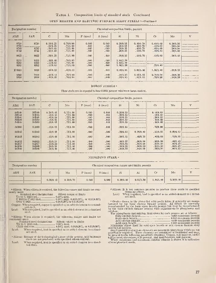
Table 1. Composition limits of standard steels—Continued
OPEN HEARTH AND ELECTRIC FURNACE ALLOY STEELS «—Continued
Designation number Chemical composition limits, percent
Aisr SAE Mn P (max) S (max) Ni Cr Mo
8720873587408742
8822
925592609262
E 9310
98409850
8720
87408742
8822
925592609262
9310
98409850
0. 18/0. 23. 33/0. 38. 38/0. 43. 40/0. 45
. 20/0. 25
. 50/0. 60
. 55/0. 65
. 55/0. 65
. 08/0. 13
. 38/0. 43
. 48/0. 53
0. 70/0. 90.75/1.00.75/1.00. 75/1. 00
. 75/1. 00
. 70/0. 95
. 70/1. 00
.75/1.00
. 45/0. 65
. 70/0. 90
. 70/0. 90
0.040.040.040.040
.040
.040
.040
.040
.025
.040
.040
0.040.040.040.040
.040
.040
.040
.040
.025
.040
.040
0. 20/0. 35. 20/0. 35. 20/0. 35. 20/0. 35
. 20/0. 35
1.80/2.201.80/2.201. 80/2. 20
0. 20/0. 35
. 20/0. 35
. 20/0. 35
0. 40/0. 70. 40/0. 70. 40/0. 70. 40/0. 70
. 40/0. 70
3. 00/3. 50
0. 85/1. 15.85/1.15
0. 40/0. 60
. 40/0. 60
. 40/0. 60
. 40/0. 60
.40/0.60
.25/0.40
1. 00/1. 40
0. 70/0. 90. 70/0. 90
0. 20/0. 30. 20/0. 30. 20/0. 30. 20/0. 30
. 30/0. 40
.08/0.15
. 20/0. 30
. 20/0. 30
BORON STEELS »
These steels can be expected to have 0.0005 percent minimum boron content.
Designation number Chemical composition limits, percent
AISI SAE Mn P (max) S (max) Ni Cr Mo
50B4050B44oOB46.5OB5050B60
51B60
81B45
86B45
94B1594B1794B3094B40
50B4050B4450B4650B5050B60
51B60
81B45
86B45
94B1594B1794B3094B40
0. 38/0. 43. 43/0. 48. 43/0. 50
. 48/0. 53
. 55/0. 65
. 55/0. 65
. 43/0. 48
. 43/0. 48
. 13/0. 18
. 15/0. 20
. 28/0. 33
. 38/0. 43
0. 75/1. 00. 75/1. 00. 75/1. 00.75/1.00. 75/1. 00
.75/1.00
. 75/1. 00
. 75/1. 00
. 75/1. 00
. 75/1. 00
.75/1.00
. 75/1. 00
0.040.040.040.040.040
.040
.040
.040
.040
.040
.040
.040
0.040.040.040.040.040
.040
.040
.040
.040
.040
.040
.040
0. 20/0. 35. 20/0. 35. 20/0. 35. 20/0. 35. 20/0. 35
. 20/0. 35
.20/0.35
. 20/0. 35
. 20/0. 35
. 20/0. 35
. 20/0. 35
. 20/0. 35
0. 20/0. 40
. 40/0. 70
. 30/0. 60
. 30/0. 60
. 30/0. 60
.30/0.60
0. 40/0. 60. 40/0. 60. 20/0. 35. 40/0. 60. 40/0. 60
. 70/0. 90
. 35/0. 55
. 40/0. 60
. 30/0. 50
. 30/0. 50
. 30/0. 50
. 30/0. 50
0. 08/0. 15
. 15/0. 25
. 08/0, 15
. 08/0. 15
. 08/0. 15
. 08/0. 15
NITRIDING STEEL «
Designation number Chemical composition ranges and limits, percent
AISI SAE C Mn P (max) S (max) Si AI Cr Mo V
0. 38/0. 43 0. 50/0. 70 0.040 0. 040 0. 20/0. 40 0. 95/1. 30 1. 40/1. 80 0. 30/0. 40
» SUicon: When silicon is required, the following ranges and limits are com-monly used:
Standard steel designations Silicon ranges or limitsUp to C 1015 excl 0.10% max.C 1015 to C 1025 incl 0.10% max, 0.10/0.20%, or 0.15/0.30%Over C 1025 0.10/0.207o or 0.15/0.30%
Copper: When required, copper is specified as an added element to a stand-ard steel.
Lead: When required, lead is specified as an added element to a standardsteel.
^ Silicon: When sUicon is required, the following ranges and limits arecommonly used:
Standard steel designations SiUcon ranges or limitsUp to C 1113 excl 0.10% max.C1113 and over 0.10%, max, 0.10/0.20%, or 0.15/0.30%.
Lead: When required, lead is specified as an added element to a stand-ard steel.
" Silicon: Because of the technological nature of the process, acid bessemersteels are not produced with specified silicon content.
Lead: When required, lead is specified as an added element to a stand-ard steel. —
^ Silicon: It is not common practice to produce these steels to specified
limits for silicon.
Lead: When required, lead is specified as an added element to a stand-
ard steel.
" Grades shown in the above list with prefix letter E generally are manu-factured by the basic electric furnace process. All others are normallymanufactured by the basic open hearth process but may be manufacturedby the basic electric furnace process with adjustments in phosphorus andsulphur.The phosphorus and sulphur limitations for each process are as follows:
Basic electric furnace 0.025 maximum percent
Basic open hearth 0.040 maximum percentAcid electric furnace 0.050 maximum percentAcid open hearth _-- 0.050 maximum percent
Minimum silicon limit for acid open hearth or acid electric furnace alloy
steel is 0.15 percent.Small quantities of certain elements are present in aUoy steels which are not
specified or required. These elements are considered as incidental and may,be present to the following maximum amounts: Copper, 0.35 percent; nickel
0.25 percent; chromium, 0.20 percent, and molybdenum, 0.06 percent.
Where minimum and maximum sulphur content is shown it is indicative
of resulpliurized steels.
27
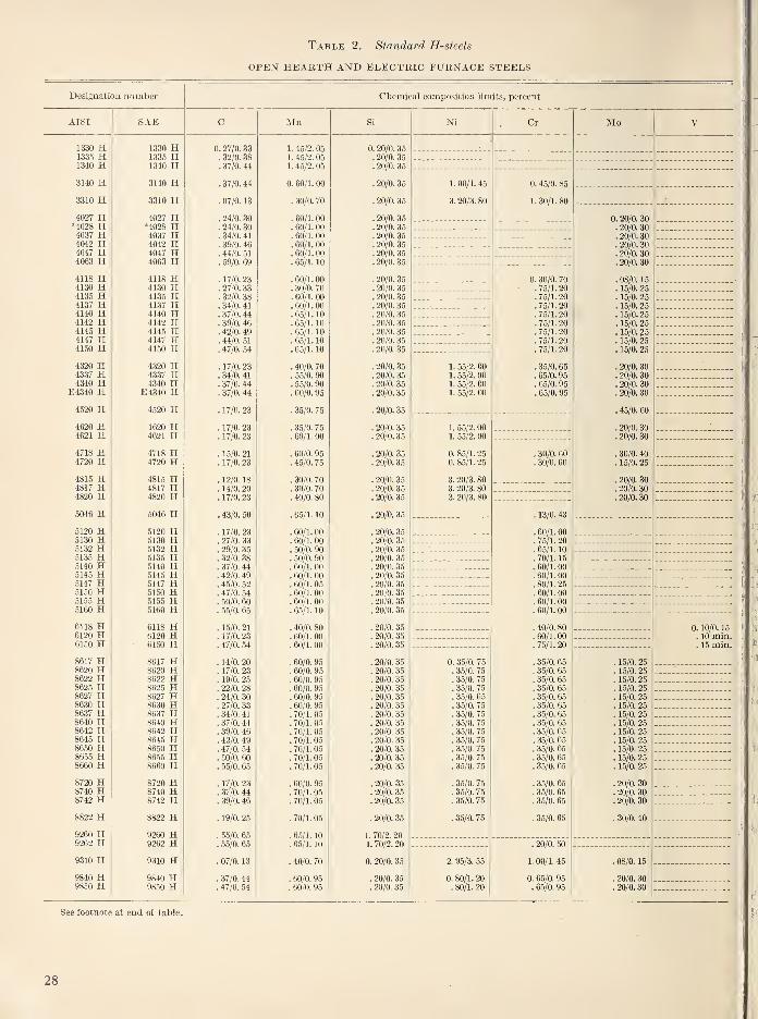
Table 2. Standard H-steels
OPEN HEARTH AND ELECTRIC FURNACE STEELS
Designation number Chemical composition limits, percent
AISI
1330 H1335 H1340 H3140 H3310 H4027 H*4028 H4037 H4042 H4047 H4063 H
4118 H4130 H4135 H4137 H4140 H4142 H4145 H4147 H4150 H
4320 H4337 H4340 H
E4340 H4520 H4620 H4621 H4718 H4720 H4815 H4817 H4820 H
5046 H5120 H5130 H5132 H5135 H5140 H5145 H5147 H5160 H5155 H5160 H6118 H6120 H6150 H8617 H8620 H8622 H8625 H8627 H8630 H8637 H8640 H8642 H8645 H8650 H8655 H8660 H8720 H8740 H8742 H8822 H9260 H9262 H9310 H9840 H9850 H
SAE
1330 H1335 H1340 H3140 H3310 H4027 H*4028 H4037 H4042 H4047 H4063 H4118 H4130 H4135 H4137 H4140 H4142 H4145 H4147 H4150 H
4320 H4337 H4340 H
E4340 H4520 H
4620 H4621 H
4718 H4720 H
4815 H4817 H4820 H
5046 H
5120 H5130 H5132 H5135 H5140 H5145 H5147 H5150 H5155 H5160 H
6118 H6120 H6150 H
8617 H8620 H8622 H8625 H8627 H8630 H8637 H8640 H8642 H8645 H8650 H8655 H8660 H8720 H8740 H8742 H
8822 H9260 H9262 H9310 H9840 H9850 H
0. 27/0. 33. 32/0. 38. 37/0. 44
.37/0. 44
. 07/0. 13
. 24/0. 30
. 24/0. 30
. 34/0. 41
. 39/0. 46
. 44/0. 51
. 59/0. 69
. 17/0. 23
. 27 '0. 33
. 32/0. 38
. 34/0. 41
. 37/0. 44
. 39/0. 46
. 42/0. 49
. 44/0. 51
. 47/0. 54
. 17/0. 23
. 34/0. 41
. 37/0. 44
. 37/0. 44
. 17/0. 23
. 17/0. 23
. 17/0. 23
. 15/0. 21
. 17/0. 23
. 12/0. 18
.14/0. 20
. 17/0. 23
. 43/0. 50
. 17/0. 23
. 27/0. 33
. 29/0. 35
. 32/0. 38
. 37/0. 44
. 42/0. 49
. 45/0. 52
. 47/0. 54
. 50/0. 60
. 55/0. 65
. 15/0. 21
. 17/0. 23
. 47/0. 54
. 14/0. 20
. 17/0. 23
. 19/0. 25
. 22/0. 28
. 24/0. 30
. 27/0. 33
. 34/0. 41
. 37/0. 44
. 39/0. 46
. 42/0. 49
. 47/0. 54
. 50/0. 60
. 55/0. 65
. 17/0. 23
. 37/0. 44
. 39/0. 46
. 19/0. 25
. 55/0. 65
. 55/0. 65
. 07/0. 13
. 37/0. 44
. 47/0. 54
Mn
1. 45/2. 051. 45/2. 051. 45/2. 05
0. 60/1. 00
. 30/0. 70
. 60/1. 00
. 60/1. 00
. 60/1. 00
. 60/1. 00
. 60/1. 00
. 65/1. 10
.60/LOO
. 30/0. 70
. 60/1. 00
. 60/1. 00
. 65/1. 10
. 65/1. 10
.65/1.10
. 65/1. 10
. 65/1. 10
. 40/0. 70
. 55/0. 90
. 55/0. 90
. 60/0. 95
. 35/0. 75
. 35/0. 75
. 60/1. 00
. 60/0. 95
. 45/0. 75
. 30/0. 70
. 30/0. 70
. 40/0. 80
. 65/1. 10
. 60/1. 00
. 60/1. 00
. 50/0. 90
. 50/0. 90
.60/1.00
. 60/1. 00
. 60/1. 05
. 60/1. 00
. 60/1. 00
. 65/1. 10
. 40/0. 80
. 60/1. 00
.60/1.00
. 60/0. 95
. 60/0. 95
. 60/0. 95
. 60/0. 95
. 60/0. 95
. 60/0. 95
.70/1.05
.70/1.05
. 70/1. 05
.70/1.05
.70/1.05
. 70/1. 05
.70/1.05
. 60/0. 95
. 70/1. 05
. 70/1. 05
. 70/1. 05
. 65/1. 10
. 65/1. 10
. 40/0. 70
. 60/0. 95
. 60/0. 95
0. 20/0. 35. 20/0. 35. 20/0. 35
.20/0.35
. 20/0. 35
. 20/0. 35
. 20/0. 35
. 20/0. 35
. 20/0. 35
. 20/0. 35
.20/0.35
.20/0. 35
. 20/0. 35
. 20/0. 35
. 20/0. 35
. 20/0. 35
. 20/0. 35
. 20/0. 35
. 20/0. 35
. 20/0. 35
. 20/0. 35
. 20/0. 35
. 20/0. 35
. 20/0. 35
.20/0.35
. 20/0. 35
. 20/0. 35
. 20/0. 35
. 20/0. 35
. 20/0. 35
. 20/0. 35
. 20/0. 35
. 20/0. 35
. 20/0. 35
. 20/0. 35
. 20/0. 35
. 20/0. 35
. 20/0. 35
. 20/0. 35
. 20/0. 35
. 20/0. 35
. 20/0. 35
. 20/0. 35
. 20/0. 35
. 20/0. 35
. 20/0. 35
. 20/0. 35
. 20/0. 35
. 20/0. 35
. 20/0. 35
. 20/0. 35
. 20/0. 35
. 20/0. 35
. 20/0. 35
. 20/0. 35
. 20/0. 35
. 20/0. 35
. 20/0. 35
. 20/0. 35
. 20/0. 35
. 20/0. 35
. 20/0. 35
. 20/0. 35
1. 70/2. 201. 70/2. 20
0. 20/0. 35
. 20/0. 35
. 20/0. 35
Ni
1.00/1.45
3. 20/3. 80
1. 55/2. 001. 55/2. 001. 55/2. 001. 55/2. 00
1. 55/2. 001. 55/2. 00
0. 85/1.250. 85/1. 25
3. 20/3. 803. 20/3. 80
3. 20/3. 80
0. 35/0. 75
. 35/0. 75
. 35/0. 75
. 35/0. 75
. 35/0. 65
. 35/0. 75
. 35/0. 75
. 35/0. 75
. 35/0. 75
. 35/0. 75
. 35/0. 75
. 35/0. 75
. 35/0. 75
. 35/0. 75
. 35/0. 75
. 35/0. 75
. 35/0. 75
2. 95/3. 55
0. 80/1. 20. 80/1. 20
Cr
0. 45/0. 85
1. 30/1. 80
0. 30/0 70.75/1 20.75/1 20.75/1 20.75/1 20.75/1 20.75/1 20.75/1 20.75/1 20
.35/0 65
. 65/0. 95
.65/0 95
.65/0 95
Mo
. 30/0. 60
. 30/0. 60
. 13/0. 43
. 60/1. 00
. 75/1. 20
. 65/1. 10
. 70/1. 15
.60/1.00
. 60/1. 00
. 80/1. 25
. 60/1. 00
. 60/1. 00
. 60/1. 00
. 40/0. 80
. 60/1. 00
. 75/1. 20
. 35/0. 65
. 35/0. 65
. 35/0. 65
. 35/0. 65
. 35/0. 65
. 35/0. 65
. 35/0. 65
. 35/0. 65
. 35/0. 65
. 35/0. 65
. 35/0. 65
. 35/0. 65
. 35/0. 65
. 35/0. 65
. 35/0. 65
. 35/0. 65
. 35/0. 65
. 20/0. 50
1. 00/1. 45
0. 65/0. 95. 65/0. 95
0. 20/0. 30. 20/0. 30. 20/0. 30. 20/0. 30. 20/0. 30. 20/0. 30
. 08/0. 15
. 15/0. 25
. 15/0. 25
. 15/0. 25
. 15/0. 25
. 15/0. 25
. 15/0. 25
. 15/0. 25
. 15/0. 25
. 20/0. 30
. 20/0. 30
. 20/0. 30
. 20/0. 30
. 45/0. 60
. 20/0. 30
. 20/0. 30
. 30/0. 40
. 15/0. 25
. 20/0. 30
. 20/0. 30
. 20/0. 30
. 15/0. 25
. 15/0. 25
. 15/0. 25
. 15/0. 25
. 15/0. 25
. 15/0. 25
. 15/0. 25
. 15/0. 25
. 15/0. 25
. 15/0. 25
. 15/0. 25
. 15/0. 25
. 15/0. 25
. 20/0. 30
. 20/0. 30
. 20/0. 30
. 30/0. 40
. 08/0. 15
. 20/0. 30
. 20/0. 30
See footnote at end of table.
28
Table 2. Standard H-steels—Continued
BORON H-STEELS
These steels can be expected to hare 0.0005 percent minimum boron content
Designation number Chemical composition limits, percent
AISI SAE Mn Ni Cr Mo
5'1B40 H50B44 H5l)B46 HoiiBoO H.511B6O H51B60 H
81B45 Hs<:,B45 H
94B15 H
94B17 H
94B30 H94B40 H
S0B40 H50B44 H50B46 H50B50 H50B60 H
51B60 H81B45 H
86B45 H
94B15 H
94B17 H94B30 H
94B40 H
0. 37/0. 44. 42/0. 49. 43/0. 50. 47/0. 54. 55/0. 65
. 55/0. 65
. 42/0. 49
. 42/0. 49
. 12/0. 18
. 14/0. 20
. 27/0. 33
. 37/0. 44
0. 65/1. 10. 65/1. 10. 65/1. 10. 65/1. 10. 65/1. 10
. 65/1. 10
.70/1.05
.70/1.05
.70/1.05
. 70/1. 05
. 70/1. 05
. 70/1. 05
0. 20/0. 35. 20/0. 35. 20/0. 35. 20'0. 35. 20/0. 35
. 20/0. 35
.20/0.35
.20/0. 35
.20/0.35
. 20/0. 35
. 20/0. 35
. 20/0. 35
0. 15/0. 45
. 35/0. 75
.25/0. 65
. 25/0. 65
. 25/0. 65
. 25/0. 65
0. 30/0. 70. 30/0. 70. 13/0. 43. 30/0. 70. 30/0. 70
. 60/1. 00
.30/0.60
. 35/0. 65
. 25/0. 55
. 25/0. 55
. 25/0. 55
. 25/0. 55
0. 08/0. 15
. 15/0. 26
. 08/0. 15
. 08/0. 15
.08/0. 15
. 08/0. 15
•Sulphur content 0.03.5/0.0.50 percent.Tlie phosphorus and sulphur limitations for each steelmaking process are
as follows:
Basic electric furnace .--0.026 percent ma.\imumBasic open hearth 0.040 percent ma.xiraumAcid electric furnace 0.050 percent ma.ximumAcid open hearth 0.050 percent maximum.
Minimum silicon limit for acid open hearth or acid electric furnace alloysteel is 0.15 percent.Small quantities of certain elements are present in alloy steels which are
not specified or required. These elements are considered as incidental andmay be present to the following maximum amounts: Copper, 0.35 percent;nickel, 0.25 percent; chromium, 0.20 percent; and molybdenum, 0.06 percent.
9.2. Tool Steels
Technically, any steel used as a tool may betermed a tool steel. Practically, however, the termis restricted to steels of special composition that
are usually melted in electric furnaces and manu-factm-ed expressly for certain types of services.
The current commonly used tool steels havebeen classified by the American Iron and Steel
Institute into six major groups and each commonlyaccepted group or subgroup has been assigned analphabetical letter. Methods of quenching, appli-
cations, special characteristics, and steels for
particular industries were considered in this typeclassification of tool steels which is as follows:
Group Symbol and type
Water hardening- - WShock resisting S
rO—-Oil hardeningCold work < A—Medium alloy
[T>—High carbon—high chromiumHot work H— (H 1 to H 19 incl. chromium base,
H 20 to H 39 incl. tungstenbase, H 40 to H 59 incl.
molybdenum base)
TT- ; „ , f T—Tungsten baseHigh speed |M-Mol?bdenum basef L—-Low alloy
Special purpose < F—^Carbon tungsten[ P—Mold steels (P 1 to P 19 incl.
low carbon, P 20 to P .39 incl.
other types)
The AISI identification and type classification
of tool steels is given in table 3. Each majorgroup, identified by a letter symbol, may contain
Table 3.
—
Identification and type classification of tool steels
Desig-nation
Identifying elements, percent
AISIC Mn Si Cr Ni v W Mo Co
WATER HARDENING
WlW2W3W4W5W6W7
"0.60/1.40".60/1.40
1.00".60/1.40
1.101.001.00
0.25.50
0.25.60.25.50
.26
.20
SHOCK RESISTING
SIS2S3S4S5
0.50.50.50.55.55
1.50 2.601.00 0.50
0.75 1.00
0.80.80
2.002.00 .40
COLD WORK; OIL HARDENING
01020607
0.90.90
1.461.20
1.001.60
0.50 0.60
1.00 0.25.75 1.75
COLD WORK; MEDIUM ALLOY AIR HARDENING
A2A4A5A6A7
1.001.001.000.702. 25
5. 001.001.001.005.25
1.001.001.001.001.00
2.003.002.00
4. 75 bl.OO
See footnotes at end of table.
29
Table 3. Identification and type classification of tool steels—-Continued
Desig-nation
Identifying elements, percent Desig-nation
Identifying elements, percent
AISIC Mn Si Cr Ni V W Mo Co
AISIC Mn Si Cr Ni V W Mo Co
COLD WORK; HIGH CARBON—HIGH CHROMIUM
DlD2D3D4D5D6D7
1.001.502. 252.251.502. 252. 35
12.0012.0012.0012.0012.0012.0012.00
1.001.00
1.001.00 3.00
1.00 1.004.00 1.00
HOT WORK; CHROMIUM BASE
HUH12H13H14H15H16
0. 35.35.35.40.40.55
5.005.005.005.005.007.00
0.40.40
1.00
1.501.501.50
1.50
5.005. 00
7.00
HOT WORK; TUNGSTEN BASE
H20H21H22H23H24H25H26
0. 35.35.35.30.45.25.50
2.003.502. 00
12. 003.004.004.00
9.009.0011.0012.0015. 0015.0018. 001.00
HOT WORK; MOLYBDENUM BASE
H41H42H43
0.65.60.55
4.004.004.00
1.002. 002.00
1.506.00
8.005.008.00
HIGH SPEED; TUNGSTEN BASE
TlT2T3T4T5T6T7T8T9T15
0.70.801.050.75.80.80.75.75
1.201.50
4.004.004.004.004. 004.504.004.004.004.00
1.002. 003.001.002.001.502.002.004.005. 00
18.0018. 0018.0018.0018.0020.0014.0014.0018.0012. 00
5. 008. 00
12.00
5.00
5. 00
a number of individual types that are identified
by a suffix number following the letter symbol.The percentages of the elements shown in the table
for each type are not to be considered as the meanof the composition ranges of the elements. Steels
of the same type, manufactured by various pro-
ducers, may differ in analysis from the valueslisted and may contain elements not listed in the
type identification.
9.3. Stainless and Heat Resisting Steels
The stainless and heat resisting steels possess
relatively high resistance to oxidation and to at-
tack by corrosive media at room and elevated
temperatures and they are produced to cover wideranges in mechanical and physical properties.
They are melted exclusively by the electric furnaceprocess.
A three-numeral system is used to identify
stainless and heat resisting steels by type andaccording to four general classes. The first digit
indicates the class and last two digits indicate
HIGH SPEED; MOLYBDENUM BASE
Ml 0. 80M2 .80M3 LOOM4 L30M6 0. 80M7 1.00M8 ° 0.80MIO .85M15 1, 50M30 0.80M33 .90M34 .90M35 .80M36 .80
4. 004. 004. 004. 004. 004. 004. 004. 004. 004,003. 754.004. 004. 00
1.002. 002. 704.001.502.001.502. 005.00L251.152. 002.002. 00
1.506. 006. 005.504.001.755. 00
6. 502.00L 502. 006. 006.00
8. 005. 005. 004. 505.008. 75
5. 008. 003. 508.009. 508. 005.005. 00
12. OO
5. 005. 008.008. 005. 008.00
SPECIAL PURPOSE; LOW ALLOY
LIL2L3L4L5L6L7
1.001 0. 50/1. 10
1.00L 001.000. 701.00
0. 601.00
0. 35
1.251.001.501. 501.000.751.40
0.20.20.25
0. 25b. 25.40
1. 50
SPECIAL PURPOSE; CARBON TUNGSTEN
Flr2r3
1.001.251.25
1. 253. 503. 500.75
SPECIAL PURPOSE: MOLD STEELS—LOW CARBON
PIP2P3P4P5P6
0.10.07.10.07.10.10
2. 000. 605. 002. 251.50
0. 501.25
0.20
3.50
SPECIAL PURPOSE; MOLD STEELS—OTHER TYPES
P20 0. 30 0.75 0. 25
I "Varying carbon contents may be available.bAt producer's option.•Cb, 1.2.5%.
type. Modification of types are indicated bysuffix letters. The meaning of this AISI systemis as follows:
Seriesdesignation Classes
2xx Chromium-nickel-manganese steels; non-hardenable, austenitic and nonmagnetic
3xx Chromium-nickel steels; nonhardenable,austenitic and nonmagnetic
4xx Chromium steels; hardenable, martensiticand magnetic
4xx Chromium steels; nonhardenable, ferritic
and magnetic5xx Chromium steels; low chromium heat resist-
ing.
The chemical composition ranges and liniits of
the standard stainless and heat resisting steels are
given in table 4.
10. Recommended Heat Treatments10.1. Structural Steels
A listing of recommended heat treatments for
many of the steels listed in tables 1 and 2 are given
in tables 5 and 6. Treatments for the standard ,
30
C3 =3
aa
ilM
oo
; IS ss
Nlliiii
If
gg ggggg
SS still
sssss sssss sssss
mil iiiit iiiit--•=22 d223S S^^^^
sssss sssss sssss sssss sssss sssss ssss SSSgg
^^^^^ S2i:2?j ??'S'3;'?32 22£'iSS ddddsj SSSS?? -^-^Ifffi iifif Ifill Iiiit
88 SSSSS SSSSS sssss SSSSS sssss sssss sssss ss„-^_:m-; d ^^^^^
ii iiili iiiii iiiii iiiii iiiil iiifi iiiii §§
ii iisss gsifg iiiii iiiii iiiii essee iiiii ii
ISS sssss sssss sssss sssss sssss ?5ssss5 sssss ssr-"d (NciciN^i c^cNriricii cificsriN !NCM>i^ri ^-Jrt^-; ^I^-^-J^- ^-^^-^-^
ii iiiii MM IMM IMi MM iiiii iSiSi iiss sssss sssss g^SSS sssss sssss S|S£;3 SSSig te2
0='
0°
m mm mm MM hmi -iiiss isill mih si
Table 5. Recommended heat treatments for carburizing grade steels
AISI or SAE number
1008 to 1024; 1108 to 1120; 1211 to 1214.
_
3310.
4012 to 4024; 4118.
4422 and 4427; 8822.
4520.
4320; 4615 to 4621; 4718 and 4720.
4815 to 4820.
5015; 5115 and 5120..
6118 and 6120.
8115; 8615 to 8622; 8720; 8822; 9310; 94B15and 94B17.
Carbuiizingtemperature
1, 650/1, 700
1, 650/1, 700
1, 650/1, 700
1, 650/1, 700
1,650/1, 700
1, 650/1, 700
1, 650/1, 700
1, 650/1, 700
1, 650/1, 700
1, 650/1, 700
Cooling method
Brine or water .
Water or oil
Cool slowly....do
Oil....doCool slowly.....do
Oil....doCool slowlv.....do
Oil...-doCool slowly.....do
Oil.-..doCool slowly......do
Oil...-doCool slowlv.....do
OU...-doCool slowly.
.do
Oil.-..doCool slowly.....do
Oil....do.Cool slowly.....do
OU....doCool slowly-....do
Reheat
1, 400/1, 4501, 400/1, 4501, 650/1, 700
1, 375/1, 425
1, 375/1, 4251, 525/1, 575
1, 425/1, 4751,425/1,475
, 1, 600/1, 650
1, 450/1, 5001, 450/1, 500
1, 625/1, 675
1, 475/1, 525
1, 475/1, 525
1, 650/1, 700
1, 425/1, 4751, 375/1, 425
1, 525/1, 575
1, 350/1, 4001, 350/1, 4001, 550/1, 600
1, 425/1, 4751, 425/1, 4751, 600/1, 650
1, 450/1, 500
1, 450/1, 500
1, 600/1, 650
1, 450/1, 5001, 450/1, 500
1, 550/1, 600
Cooling medium 2d reheat Cooling medium
Brine or water.do
Water or oil
OU..do..do.
OU..do..do.
OU..do..do.
OU..do..do.
OU..do..do.
OU..do..do.
OU..do.-do-
Oil or water.do
OU...
OU..do.,
.do..
1,400/1,450
1, 375/1, 425
1, 425/1, 475
1, 450/1, 500
1, 475/1, 525
1, 375/1, 425
1, 350/1, 400
1, 425/1, 475
1, 450/1, 500
1,450/1,500
Brine or water.
Oil.
OU.
OU.
OU.
OU.
OU.
OU.
Oil or water.
OU.
Temperingtemperature
° F
250/300
250/300
250/300
250/300
250/300
250/300
250/300
250/300
300/400
250/300
Ml
Table 6. Recommended heat treatments for heat treating grade steels
(No tempering treatments are given, as these temperatures depend upon the desired hardness)
AISI or Normalizing Annealing Hardening Quenching AISI or Normalizing Armealing Hardening Quenchinglllj
toSAE temperature temperature temperatui'e medium SAE temperatui-e temperature temperature mediumnumber number
0p "F "F op op op1030 1,626/1,725 1,525/1,575 1,550/1,600 Water or brine. 6046 1,600/1,700 1,476/1,525 1,500/1,560 OU.1040 1,600/1,700 1,476/1,526 1,500/1,550 Do. 5130 1,600/1,700 1,600/1,660 1,550/1,600 Oil or water.1050 1,550/1,650 1,450/1,500 1,475/1,525 Do. 6146 1,600/1,700 1,475/1,526 1,626/1,575 OU.
' llD
1060 1,500/1,600 1,425/1,475 1,460/1,600 Do. 6160 1,600/1,700 1,450/1,500 1,600/1,650 Do.1070 1, 500/1 600 1,425/1,475 1,450/1,500 Do. 50100 1,600/1,700 1,400/1,450 1,450/1,600 Do.
«f
1080 1,475/1,575 1,375/1,425 1,400/1,460 Do. 51100 1,600/1,700 1,400/1,450 1,476/1,525 Do.1090 1,475/1,575 1,375/1,425 1,400/1,450 Do. 52100 1,600/1,700 1,400/1,450 1,500/1,550 Do. '
(T
1132 1,625/1,725 1,526/1.575 1,550/1,600 Do. 6160 1,600/1,700 1,500/1,550 1 , 650/1, 600 Do.1140 1,600/1,700 1,475/1,525 1,600/1,660 Do. 8630 1,600/1,700 1,500/1,550 1,626/1,575 Do. ill
1151 1,550/1,650 1,460/1,500 1,475/1,525 Do. 8646 1, 600/1, 700 1,476/1,525 1,600/1,650 Do.Pl
1330 1,600/1,700 1,500/1,550 1,525/1,676 Oil or water. 8660 1,600/1,700 1,450/1,500 1,475/1,525 Do. «il
1340 1,550/1,650 1,476/1,626 1,500/1,550 Do. 8735 1,660/1,700 1,500/1,550 1,526/1,575 Do.a3140 1,650/1,650 1,475/1,525 1,475/1,525 OU. 8742 1,600/1,700 1,600/1,650 1,525/1,575 Do.
4028 1,600/1,700 1,525/1,575 1,550/1,600 OU or water. 9260 1,600/1,700 1,500/1,660 1,550/1,600 Do.to
4042 1,550/1,660 1,475/1,625 1,600/1,560 Oil. 9840 1,600/1,700 1,476/1,626 1,500/1,560 Do. 1
9860 1,600/1,700 1,475/1,525 1,500/1,550 Do. '
ki
4063 1,550/1,650 1,450/1,500 1,475/1,525 Do.4130 1,600/1,700 1,525/1,575 1, 560/1, 600 Oil or water. us
4140 1,600/1,700 1,500/1,550 1, 626/1, 676 Oil. ([
4150 1,600/1,700 1,475/1,525 1,600/1,650 Do.to
s
4340 1,600/1,700 1,600/1,650 1,500/1,550 Do.
steels that are omitted can be estimated by inter-
polation (also see fig. 11). Where different
quenching media are suggested, the smaller sec-
32
tions may harden satisfactorily in the slower
quenching medium. The upper end of the heattreating ranges should always be used for large
I size sections. The inclusion of normalizing andannealing temperatm-es does not imply that these
treatments are necessarily a prelude to hardening.
For hardening, the general rule is to place thecold steel in a fui'nace containing a slightly oxidiz-
ing atmosphere or neutral salt bath at the harden-ing temperature and let it heat natmally, holdhx/'m of thickness, and then quench; it is sometimesadvisable to warm intricate sections or complexshapes before putting them into the high tempera-tui'e unit and to remove fi'om the quenchingmedium while still warm. Usually, the quenchedpiece should be allowed to cool until it can becomfortably held in the bare hand and then im-mediately tempered. To minimize cracking, it is
sometimes desirable to temper the quenched piece
before it reaches room temperatm-e ; a double tem-per (i.e., repeating the treatment) is recommendedfor this condition.
For carburizing, most of the steels may be giveneither (1) a single, (2) double, or (3) triple treat-
ment as is indicated in table 5. The time at thecarburizing temperature will vary depending uponthe temperature used and the desired thickness of
the case. The relation between time, tempera-ture and case depth is illustrated m figm'e 19.
10.2. Tool Steels
Recommended heat treatments for the different
types of tool steels are summarized in table 7.
The time the steel is at the normalizing temper-ature, after being heated uniformly through, varies
from about 15 min for a small section to about 1
hr for large sizes; cooling from the normalizingtemperature is in still air. For annealing, theupper range in temperatm-e is recommended for
large and the lower limit for small sections. Thetime the steel is at the annealing temperature,after being heated uniformly through, ranges fromabout 1 hr for thin sections of carbon or low alloy
to about 4 hr for heavy sections of high alloy
steel. Cooling from the annealmg temperatiirethrough the transformation range should not ex-
ceed about 75° F/hr for the carbon and low alloy
and 50° F/hr for the high alloy steels.
For hardening, the protective atmosphere, rateof heating, hardening temperature, time at temp-erature, and rate of cooling vary with the compo-sition of the steels. A general rule is to heat theplain carbon and low alloy steels rapidly m a fiu"-
nace having a slightly oxidizing atmosphere or in
a neutral salt bath at the hardening temperature,hold K hr/in of thickness, and then quench. Thehigh alloy steels, such as the T and M types, areusually preheated to minimize distortion andcracking and then heated rapidly in a furnacecontaining a highly carburizing atmosphere or in
a molten bath at the hardening temperature, heldat temperature for time as indicated in the table,
and then quenched. Tools should be temperedimmediately after quenching; a double temper is
recommended for the high alloy steels.
The carbm'izing steels (type P) may be (1)
quenched dhectly from the carburizing tempera-tm*e; (2) quenched directly from the carburizingtemperature followed by quenching from therecommended hardening temperature; (3) slowlycooled from the carburizing temperature followedby quenching from the recommended hardeningtemperatm*e; or (4) slowly cooled from the car-
bmizing temperature, reheated to the carburizingtemperature and quenched, followed by reheating to
and quenching from the recommended hardeningtemperatm-e. For most pm-poses, method (3) is
generally suitable. Tempering should follow in
all cases.
10.3. Stainless and Heat Resisting Steels
The response of stainless and heat resistihg
steels to heat treatment depends upon their com-position. The general methods employed are
similar to those used with other steels and nospecial equipment is needed. Heat treatmentmay be performed in any conventional electric,
gas fired, oil fired, salt bath, or induction furnacein which the requhed temperatures can beobtained. Precautions should be taken to avoidexposure of the steel to the direct flame of theburners. Conditions that will result in carburi-
zation of the surface of the steel should be avoided.In general, oxidizing furnace atmospheres are
preferred. Bright, scale-free heat treatment is
possible by the use of specially prepared andcontrolled atmospheres.The stainless steels may be divided into three
general groups 'as follows:
a. Group I—Hardenable Chromium Steels (Martensiticand Magnetic)
These steels respond to heat treatment in amanner similar to most lower alloy steels and will,
by suitable thermal treatment, develop a widerange of mechanical properties. The temperingrange of 700° to 1000° F. should be avoidedbecause it is conducive to increased brittleness.
b. Group II—Nonhardenable Chromium Steels (Fer-ritic and Magnetic)
These steels are essentially nonhardenable byheat treatment. They develop their maximumsoftness, ductility and corrosion resistance in the
annealed condition.
c. Group III—Nonhardenable Chromium-Nickel andGhromium-Nickel-Manganese Steels (Austenitic andNonmagnetic)
These steels are essentially nonmagnetic andcannot be hardened by heat treatment. Coldworking develops a wide range of mechanicalproperties and some of these steels, in the severely
cold worked condition, may become slightly
magnetic. They are annealed by rapidly cooling
(air or water) from high temperatures to develop
maximum softness and ductility as well as corro-
sion resistance.
Recommended heat treatments for the steels
listed in table 4 are given in table 8.
33
Table 7. Recommended heat treatments for tool steels
Normalizingtemperature
Annealing
TemperatureBrinellhardnessnumber
Hardening
Preheatingtemperature
Quenchingtemperature
Quenchingmedium
Tempering
Temperature
o p1,450/1, 700
1,450/1, 700 »
1, 450/1, 700 »
1, 450/1, 700 ^
1, 450/1, 700 >
1,450/1,700"1, 450/1, 700 >
(«)
C).
Col
(")
1, 500/1, 6001, 500/1, 550
1, 600/1, 650
1,600/1,650
600/1,650
600/1, 650
600/1,650
600/1, 650600/1, 650
600/1, 650600/1, 650
1, 375/1, 4501, 400/1, 450
1,400/1,4501,375/1,450
1, 400/1, 450
1, 400/1, 4501, 400/1, 450
1, 450/1, 500
1, 400/1, 4501, 450/1, 600
1, 400/1, 450
1, 400/1, 450
1, 400/1, 4501,375/1,4251, 400/1, 450
1, 450/1, 500
1,550/1,6001, 350/1, 4001, 350/1, 4001, 350/1, 3751, 600/1, 650
1, 600/1, 6501, 600/1, 6501, 600/1, 650
1, 600/1, 6501, 600/1, 6501, 600/1, 6501, 600/1, 650
1, 550/1, 650
1, 550/1, 650
1, 550/1, 6501, 600/1, 6501, 550/1, 6001,600/1,6501,600/1,6501, 600/1, 6501, 600/1, 6501, 600/1, 6501, 600/1, 6501,600/1,6501, 600/1, 6501, 500/1, 6001,550/1,650
1, 500/1,600
1,600/1,6501, 600/1, 6501, 600/1, 6501, 600/1, 6501, 600/1, 6501, 600/1, 6501, 600/1, 650
1, 600/1, 6501, 600/1, 6501, 600/1, 650
1,500/1,6001,600/1,6501,600/1,6501,600/1,650
1, 500/1, 600
1, 500/1, 6001,550/1,6001, 500/1, 6001,600/1,6501,600/1,6501,600/1,6501,600/1,6501,600/1,6601,600/1,650
1, 426/1, 475
1, 400/1, 450
1, 450/1, 500
1,425/1,4751,425/1,4751, 400/1, 4501,450/1,500
(BHN)169/202
169/202163/202169/202
163/202163/202163/202
183/229192/217
183/212
192/229
192/229
183/212183/212183/217
192/217
202/229200/241228/265217/248235/262
207/248217/255217/255217/265223/256217/255235/262
192/229
192/229192/229
207/236207/229212/241207/236207/235207/235213/255217/241207/236217/241
207/235207/235207/235
217/255223/255229/269229/269235/275248/293217/256229/255235/277241/277
207/235212/241223/255223/255248/277217/255217/241207/236241/277236/269236/269235/269235/269235/269
179/207
163/196
174/201
179/207183/223183/212183/212
o p(•>)
mC)(")
C")
C-)('')
(•>)
1, 100/1, 200
1, 100/1, 200
1, 100/1, 200
1, 300/1, 400
1, 100/1, 2001,100/1,2001, 100/1, 200
1, 100/1, 200
1,360/1,4501, 150/1, 250
1, 100/1, 2001, 100/1, 2001, 400/1, 500
1,400/1,5001, 400/1, 6001, 400/1, 500
1, 400/1, 5001, 400/1, 500
1, 400/1, 500
1, 400/1, 500
1, 400/1, 600
1, 400/1, 500
1, 400/1, 500
1, 400/1, 500
1, 600/1, 600
1, 500/1, 6001,600/1,600
1, 500/1, 600
1, 500/1, 600
1, 600/1, 6001,500/1,600
1, 500/1, 600
1, 600/1, 600
1, 360/1, 650
1, 360/1, 650
1, 360/1, 650
1, 500/1, 600
1, 500/1, 600
1, 500/1, 600
1, 500/1, 600
1, 600/1, 6001, 500/1, 600
1, 500/1, 600
1, 500/1, 6001, 500/1, 6001, 600/1, 600
1, 350/1, 550
1, 350/1, 550
1, 350/i, 550
1, 350/1, 550
1, 400/1, 600
1,350/1, 650
1, 400/1, 650
1, 350/1, 550
1, 500/1, 6001,350/1,550
1, 360/1, 550
1, 350/1, 550
1, 350/1, 550
1, 350/1, 550
(")
C-)
C')
(")
(")
C)(")
o p1, 426/1, 475
1, 450/1, 5001, 450/1, 5001, 425/1, 4751, 425/1, 4751, 450/1, 5001, 450/1, 500
1, 650/1, 800<l 1,550/1,650
1, 500/1, 600/<i 1,600/1,700
V 1, 650/1, 750<i
1, 600/1, 700
1, 450/1, 500"i 1, 400/1, 476<i
1, 450/1, 500fl, 450/1, 525
11, 650/1, 625
1, 700/1, 8001, 600/1, 6001, 450/1, 650
1, 525/1, 600
1, 750/1, 800
1,775/1,8501, 800/1, 8751,700/1,8001, 776/1, 8601, 800/1, 875
1, 700/1, 750
1, 850/1, 950
1, 825/1, 8751,825/1,8751, 825/1, 900I, 850/1, 950
2, 100/2, 300<! 2, 050/2, 160e 2, 000/2, 200e 2, 000/2, 200' 2, 000/2, 200e 2, 200/2, 325< 2, 000/2, 250' 2, 100/2,300e 2, 150/2, 300d 2, 000/2, 175i
2, 050/2, 225
2, 000/2, 175
» 2, 300/2, 375e 2, 300/2, 3750 2, 250/2, 326' 2, 300/2, 375< 2, 325/2, 400e 2, 325/2, 400" 2, 300/2, 350<2, 300/2, 375
« 2, 275/2, 325« 2, 200/2, 300
e 2, 150/2, 225e 2, 176/2, 250e 2, 200/2, 250o2, 200/2, 250
« 2, 150/2, 200s 2, 150/2, 240' 2, 200/2, 300e 2, 150/2, 225e 2, 175/2, 250
2, 200/2, 250«2, 200/2, 250
' 2, 200/2, 250" 2, 225/2, 275« 2, 225/2, 275
1, 450/1, 550II, 450/1, 550
11, 560/1,700fl, 426/1, 500
U, 500/1, 6001,475/1,6001,450/1,600
1, 450/1, 560
1, 500/1, 600
Brine or water.do-dododododo
OilBrine or water.-..do— _doOil.—_.._do
Oil.__.do-___.do.Water-Oil
Air..
-do..do.-do..do.
Air..
Oil.
Air..
-do.
Oil-Air.,
.do-
Air --
dododo
Air, or oil
dodododo-dodo .-
do-Air, oil, or salt-
dododo —
-
Oil, au-, or salt.
dododo-do- -
do.do.do-do -
-do
Oil, air, or salt-
dodododo .—do- .--do.do.do.do -
.do-do-do.-do
Oil or water..WaterOilWaterOilOil or water.Oil
dodo
o p300/650300/650300/660300/660300/650300/650300/660
400/1, 200300/800300'600
350/800
350/800
300/500300/500300/600
325/550
350/1. 000300/800300/800300/800
300/1, 000
400/1,000400/1, 000400/1, 000400/1, 000400/1, 000400/1, 000300/1, 000
000/1, 200000/1, 200000/1, 200100/1, 200100/1, 200
050/1, 250100/1,250100/1, 250100/1, 250200/1, 500050/1. 200050/1, 260050/1, 250050/1, 200050/1, 200050/1, 200
000/1, 100000/1, 100000/1, 100000/1, 100000/1, 100000/1, 100000/1, 100000/1, 100000/1,100000/1,200
000/1, 100000/1, 100000/1, 100000/1, 100000/1, 100000/1, 100000/1, 100000/1, 100000/1, 200000/1,100000/1, 100000/1, 100000/1, 100000/1, 100
300/600
300/1, 000
300/600
300/600300/600
300/1, 000300/600
See footnotes at end of table.
34
Table 7. Recommended heat treatments for tool steels—Continued
AISItype
N'ormalizingtemperature
Annealing Hardening Tempering
TemperatureBrinellhardnessnumber
Preheatingtemperature
Quenchingtemperature
Quenchingmedium Temperature
Rockwellhardnessnumber
FlF2F3
" F1, 600/1, 6501, 600/1, 6501,600/1,650
o p1,400/1,4751,450/1,5001, 450/1, 500
{BHN)183/207207/235212/248
° F1, 100/1, 2001, 100/1, 2001, 100/1, 200
o p1, 500/1, 6001,500/1.600
1, 500/1, 600
Water or brine.
° F300/500300/500300/500
(Rc)64/6066/6266/62
doWater, brtue, or oil
CARBURIZIN-Q GRADES
AISItype
ISTormalizingtemperature
AnnealingCarburizingtemperature
Hardening Tempering
Temperature Hardness Temperature Quenching medium Temperature Rc of case
op ° F (BHIST) 0 p ° F ° pPI 1. 350/1, 650 81/100 1, 650/1, 700 1,450/1,475 Water or brine -„ 300/500 64/58P2 1, 350/1. .500 103/123 1, 650/1, 700 1.525/1,550 Oil 300/500 64/58P3 1, 350/1, .500 109/137 1, 650/1, 700 1, 475/1. 525 do 300/500 64/58
P4 1,600/1.650 116/128 1, 775/1, 825 1, 775/1, 825 Air - 300/500 64/58
P5 1, 550/1.600 105/110 1, 650/1, 700 1, 550/1, 600 Oil or water 300/500 64/58P6 1. 550/1, 600 190/210 1, 650/1. 700 1, 4.50/1, 500 Oil 300/450 61/58
P20 1625 to 1675 1, 400/1, 450 150/180 1,600/1,650 1, 500/1, 600 do 300/500 64/58
' N'ormalizing:0.60 to 0.75% C, 1500° F;.75 to .90% C, 1450° F;.90 to 1.10% C, 1600° F;
1.10 to 1.40% C, 1600° to 1700° F.
j Preheating not necfessary.» Do not normalize.^ Do not soalv.e Time at hardening temperature, 2 to 5 min.' Double tempering recommended,e Normalizing not required.
Table 8. Recommended heat treatments for stainless and heat resisting steels
GROUP I. HARDENABLE CHROMIUM STEELS (MARTENSITIC AND MAGNETIC)
AISIAnnealing » Hardening i> Stress relieving Tempering
typeTemperature Hardness Temperature Hardness Temperature Hardness Temperature Hardness
403410414416416 Se420431440 A440 B440 C.501
"F1..5.50;1,650
1. .5,50/1. 6.50
= 1, 200/1, 3001, .5.50/1, 650
1, 550/1, 6.50
1,6{|0'1,6.50
M. ir.n 1.22.^.
75/83 Rb7.5/85 Rb
98 Rb/24 Rc78/83 Rb80/90 Rb81 '89 Rb
'17 K 1, 24 RcIM '.15 Rb:n 'M Rb9.5/99 Rb80/90 Rb72/80 Rb
°F1, 700/1, 8501, 700/1, 850
1, 800/1, 9501. 700/1, 850
1, 700/1, 8.50
1. 800/1. 9001.800/1,9501.8,50/1.9.50
1,8.50/1.9.50
1, 850/1, 9501,600/1,700
m
39/43 Rc39/43 Rc42/47 Rc40/44 Rc39/43 Rc53/56 Rc42/46 Rc55/58 Rc57/59 Rc60/62 Rc35/45 Rc
op
450/700450/700450/700450/700450/700300/700450/700300/700300/700300/700
40/37 Rc40/37 Rc44/40 Rc40/37 Rc40/37 Rc53/48 Rc42/36 Rc56/51 Rc58/53 Rc60/55 Rc
°F1, 000/1, 4001,000/1.4001,100/1,3001,000/1.4001,000/1.400
.34 Rc/86 Rb34 Ec/86 Rb29 Rc/99 Rb34 Rc/86 Rb34 Rc/8fi Rb
1. 000/1, 200 35 Rc/99 Rb
L ' K6751, 1.600 400/1. 200 45/25 R 0
502 1.52.51,600
GROUP II. XOXHARDEXABLE CHROMIUM STEELS(FERRITIC AND MAGfNETIC)
AISItype
Annealing «
Temperature Hardness,Rb
°F405 1, 350/1, 500 70/80430 1. 400/1, 500 80/90430 F 1,350/1, .500 80/90430 F Se 1, 350/1, 500 80/90446 1, 500/1, 600 80/90
GROUP III. NONIIARDENABLE CHROMIUM-NICKEL ANDCHROMIUM-NICKEL-MANGANESE STEELS (AUSTENITICAND NONMAGNETIC)
AISI Annealing AISI Aimcahngtype temperature
'
type temperatui'e
'
°F op
201 1, 850/2. 050 309 1,900/2, 050
202 1, 850/2, 0.50 309 S 1,900/2, 050
301 1,850/2,050 310 1, 900/2, ( 50
302 1, 850/2, 050 310 S 1,900/2, 050
302 B 1, 850/2, 050 314 2, 000/2, 100
303 1. 850/2, 050 316 1, 850/2, 050
303 Se 1, 850/2, 050 316 L 1. 850/2, 050
304 1, 850/2, 050 317 1, 850/2, 050
304 L 1, 850/2, 050 321 1, 750/1, 950
305 1, 850/2, 050 347 1,850/1. 950
308 1, 850/2, 050 348 1, 850/1, 950
Cool slowly to 1,100° F.^ Although these steelsTTafden appreciably on air cooling, quenching in oil is preferable.' Full annealing impractical; may he air cooled from indicated temperature.<< Generally used in annealed condition only.' Air fOOl.
, 1, T>' Cooling may be in air or by quenching in water. The resultant hardness of all of these steels will be in the range of approximately Rockell B I I to 90.
35
11. Properties and Uses of Steels
11.1. Structural Steels
The strength properties of heat treated(quenched and tempered) structural carbon andalloy steels are closely related to their hardnessand are surprisingly similar for a selected hardnessprovided that the steels originally were hardenedthroughout their cross sections. The relation of
tensile strength, yield strength, elongation, andreduction of area to hardness is shown in figure 27.
The tempering temperatures necessary to securecertain hardness levels in steels are affected byalloying elements, and two different steels mayhave to be tempered at two different temperaturesto secui'e the same hardness. When this has beenaccomplished, however, the strength and ductility
of the two steels will be quite similar. It must beemphasized that these relationships are valid onlyif the heat treated structures are tempered marten-site. A steel that has been incompletely hardened(that is, quenched at too slow a rate to prevent the
formation of some fine pearlite) may have, after
tempering, a hardness and tensile strength equal
to that of a completely hardened and temperedsteel, but its yield strength and ductility will beinferior.
HARDNESS .ROCKWELL C
5 7025 30 35 40 45
< 60u_O
g 40
30
od 10
- 220<no.
0 200O
X 180I-
1 160I-<o
a 140_iUJ
^ "20
IiJ
100
1 11 1 1 1 1 1 1 1 1 1 1 1 1 1 1 1 1 1 1
REDUCTIONOF AREA
ELONGATION
. 1 ] 11 1 1 _l L. _l L
UJt- 80
1 1 1 1 1 1 1 I 1 1 1 1 1 1 1 1 1 1 1 1
TENSILE STRENGT
lELD STRENGTH
1 1 11 1 1 1 1 J_J 1 1 1 1
1,1 L 1 1 1 t
240 280 320 360 400BRINELL HARDNESS NUMBER
440
Figure 27. Tensile strength, yield strength, elongation,
and reduction of area as a function of hardness in struc-
tural steels.
Valid only for steels originally hardened throughout and then tempered.Although drawn as lines, the relationship between these properties is notexact, and some deviations may be expected.
36
The modulus of elasticity of steel is the same asthat of iron (about 29,000,000 Ib/m.^). It is notaffected by heat treatment or by the addition ofalloying elements. Since stiffness, or the resistanceto deformation under load, is a function of themodulus of elasticity, it follows that the stiffness
of steel cannot be changed by heat treatment orby alloying elements, provided that the total stress
j
is below the elastic limit of the steel in question.Either heat treatment or alloying elements canraise the elastic limit and thus apparently improvethe stiffness in that higher allowable unit stresses
may be imposed on the steel.
a. Plain Carbon Structural Steels
The plain carbon steels are the least costly and Is
may be used for a variety of purposes. The lowercarbon grades (up to about 0.25% of carbon), fre-
quently termed machmery steels, are used in thehot- and cold-worked conditions and for carburiz-
ing. Except when carbm-ized, they are not veryresponsive to hardening by heat treatment becauseof the low carbon content. The medium carbonsteels (about 0.30 to 0.60%) are the forging gradesand are commonly used in the heat-treated condi-tion. The higher carbon grades are the spring andtool steels.
Carbon steels are essentially shallow-hardening,usually requiring a water or brine quench, althoughvery small sections may be successfully hardenedin oil. Even with the most drastic quench, theycannot be hardened throughout even in moderate(about %-in.) cross sections. Large cross sections
(about 4 in.) cannot be fully hardened even onthe surface except by induction or flame hardening.
b. Alloy Structural Steels
From the viewpoint of heat treatment, the ad-vantages accruing from the use of alloy steels are
threefold: (a) Increased hardenability, (b) reten-
tion of fine-grained austenite, and (c) retardation
;
of softening during tempering.j
All of the alloying elements commonly used inf
structural alloy steels are effective to varying\
degrees in displacing the S-curve to the right as .
compared with plain carbon steels of similar car-
bon contents. Consequently, they can be hardenedthroughout in larger sections and, generally, bymeans of a milder quenching medium, such as oil.
Because of the slower rates of quenching that canbe employed in hardening these steels, they are ;
less likely to distort or crack during hardening[
than the plain carbon steels.
The hardenability of alloy steels varies widely,
depending on the composition. Certain elementsand combinations of elements are very effective
in increasing hardenability. Of the five alloying
elements most generally used, and within theamounts normally present m the structm-al steels,
nickel enhances hardenability but mildly, vanadi-um, chromium, manganese, and molybdenummoderately to strongly, depending upon theamount of alloy dissolved in the austenite at the
hardening tempera tiu"e. Combinations of chi'O-
mium, nickel, and molybdenum, such as are
present in the 4300 series (table 1), result in verydeep hardeniag steels.
The alloying elements that form stable carbides,
principally vanadium and molybdenum (andchi-oniium to a lesser degree), are very effective in
inhibiting grain growth in austenite. These steels
may be overheated to a considerable degree dmingheating for hardening without suffering grain
growth. This is deshable since martensite formedfrom fine-gi'ained austenite is tougher than thatformed from coarse-grained austenite.
AUoying elements, particularly those that formthe more stable carbides, tend to retard the soften-
ing effects of tempering so that alloy steels mustfrequently be tempered at higher temperaturesthan carbon steels in order to secm'e the samehardness. This is beneficial in conferring in-
creased toughness, i.e., resistance to shock.It is pertinent to note that manganese and nickel
lower the annealing and hardening temperatures,and that chi'omium, molybdenum, and vanadiumraise these temperatm-es. Combinations of these
alloys may therefore, raise, lower, or have no effect
on the heat-treating temperatures, depending onthe combinations of elements and their amounts.The low carbon (up to about 0.25% of carbon)
alloy steels are used mainly as carburizing steels.
The medium carbon (about 0.30 to 0.60% of car-
bon) alloy steels find wide use as stressed membersin an almost infinite variety of structural parts.
Although some of these alloy steels containinghigh carbon are used for certain special applica-
tions, the maximum amount of carbon present in
the alloy structural steels is generally about 0.5
percent.
11.2. Tool Steels
Practical experience has shown that in amajority of instances the choice of a tool steel is
not limited to a single type or even to a particular
family for a working solution to an individualtooling problem. It is desirable to select thesteel that will give the most economical overall
performance; the tool life obtained with each steel
under consideration should be judged by weighingsuch factors as expected productivity, ease of
fabrication, and cost.
Hardness, strength, toughness, wear resistance,
and resistance to softening by heat are primefactors that must be considered in selecting tool
steel for general applications. Many other factors
must be considered in individual applications;they include permissible distortion in hardening,permissible decarburization, hardenability, resist-
ance to heat checking, machinability, grindability,
and heat treating requirements.The straight carbon tool steels can be used for a
variety of purposes, depending upon the carboncontent and heat treatment. The lower carbonranges are used for tools where toughness andresistance to shock are of primary importance;
these steels are usually tempered at temperaturesof 500° to 700° F or even higher. The highercarbon ranges are used where the main require-ments are hardness, resistance to abrasion, orability to hold a keen edge ; these steels are usuallytempered at temperatmes of 300° to 500° F.An addition of 0.20 to 0.50 percent of chromium
or of vanadium is frequently made to the carbontool steels. The chromium-bearing carbon steels
have a greater depth of hardnening and are
slightly more wear-resistant than the chromium-free steels of the same carbon content. Vanadiumdecreases slightly the depth of hardening butincreases toughness. (This may appear contra-
dictory to previous statements that alloying
elements increase hardenability. In the case of the
carbon-vanadium tool steels, the normal hardeningtemperatures are too low to allow the solution of
vanadium carbide in the austenite. The presence
of undissolved carbides decreases hardenability).
The cutting ability, or the ability to hold anedge, is closely related to the hardness. For mostpurposes, therefore, cutting tools are used in
a highly hardened condition. Excessive heat,
whether caused by heavy cutting or careless
gi-incling, will "draw the temper" (that is, decrease
the hardness) and ruin the tool, necessitating
rehardening and retempering. Since hardenedcarbon steels soften rapidly under the influence of
heat, the carbon steels cannot be used as cutting
tools under conditions where an appreciable
amount of heat is generated at the cutting edge.
Theu' uses are limited to conditions entailing light
cuts on relatively soft materials, such as brass,
aluminum, and unhardened low carbon steels.
The ranges for the carbon content and sometypical applications of carbon tool steels are as
follows:
0.60 to 0.75 percent of carbon—Hot forming or
heading dies for short runs, machinery parts,
hammers (sledges and pinch bars), concrete
breakers, and rivet sets.
0.75 to 0.90 percent of carbon—Hot and cold
sets, chisels, dies, shear blades, mining drill steel,
smiths' tools, set hammers, swages, and flatteners.
0.90 to 1.10 percent of carbon—Hand chisels,
small shear blades, large taps, granite drills, trim-
ming dies, drills, cutters, slotting and milling tools,
mill picks, chcular cutters, threading dies, colcl
header dies, jewelers' cold striking dies, blanking,
forming and drawing dies, and punches.
1.10 to 1.40 percent of carbon—Small cutters,
small taps, drills, reamers, slotting and planing
tools, wood-cutting tools, turning tools, and razors.
Suitable tempering temperatures for carbon tool
steels are as follows:
300° to 375° F—Lathe tools and millmg cutters,
scrapers, drawing mandrels, dies, bone-cutting
tools, engraving tools, gages, and threading dies.
375° to 500° F—Hand taps and dies, handreamers, di'ills, bits, cutting dies, pen knives, mill-
ing cutters, chasers, press dies for blanking andforming, rock drills, dental and surgical instru-
37
ments, hammer faces, wood-carving tools, shearblades, and hack saws.
500° to 700° F—Bending dies, shear blades,
chuck jaws, forging dies, tools for wood cutting,
hammers and drop dies, axes, cold chisels, copper-smith tools, screwdrivers, molding and planingtools, hack saws, butcher knives, and saws.The high-speed steels are intended for use under
heavy cutting conditions where considerable heatis generated. These steels are very complex, con-taining large amounts of alloying elements. Thehigh-speed steels, which harden from a very hightemperature (2,150° to 2,400° F), develop whatis termed "secondary hardness" after temperingat about 1,050° to 1,100° F and maintain their
cutting edge at considerably higher temperaturethan do carbon tool steels.
Dies, depending on their use, can be made of a
variety or steels. When intended for use at lowtemperatures, even carbon steel may be satisfac-
tory sometimes. For use at elevated temperatures,certain minimum amounts of alloying elements are
necessary and for the higher ranges of hot-workingtemperatures, steels of the high-speed steel typeare frequently used.
The manufacture of dies usually involves suchconsiderable expense in machining that cost of
material and heat treatment form but a relatively
small proportion of the total. It is imperative,
therefore, that die steels be selected carefully andproperly heat treated. The so-called "nondeform-ing" tool steels (type O) are favorites for dies that
are not required to operate at elevated temper-atures. These steels usually contain about 0.9
percent of carbon and 1.2 percent to 1.6 percent of
manganese. With the lower manganese contentthey also contain about 0.5 percent each of chro-
mium and tungsten. The expansion of these steels
during hardening is much less than is experiencedwith carbon steels, and the shrinlvage that occm-sduring the initial stage of tempering is almostsufficient to return the steel to its original size
when it has been tempered at the proper temper-atiu'e.
The high carbon-high chromium steels (type D)are frequently used for dies. This type containsabout 12 percent of chromium and 1.5 or 2.2
percent of carbon, the lower carbon steel beingair hardening. These steels also are nondeforming,are more resistant to wear, and may be used at
higher temperatures than the manganese nonde-forming steels. They have the disadvantage of
requiring higher hardening temperatures (about1,800° F).
11.3. Stainless and Heat Resisting Steels
Steels for high-temperature service must resist
scaling and have high creep strength, that is, re-
sistance to deformation under prolonged stress at
elevated temperatures. Resistance to scaling is
aided by the presence of chromium, aluminum, or
silicon, and heat-resistant steels invariably containone or more of these elements. Resistance to creep
era!
lilt 11
Tv
is aided by elements that form stable carbidessuch as tungsten, vanadium, molybdenum, ancchromium.The stainless steels, often called corrosion-resist-,
ant steels, contain appreciable amounts of chro-^
mium (12% or more), either with or without otheii
elements, the most important of which is nickel.
The heat-resistant and corrosion-resistant steels
all belong to the same family, the terminologyfrequently being dictated by the temperature of
use. By common consent, this dividing temper-ature is taken at about 1200° F.The three general groups of stainless steels hav€|
markedly different characteristics, as follows:
a. Group I —Hardenable Chromium Steels (MartensitiCj^
and Magnetic)
The significant characteristic of this group is* f^ist
that the steels respond to heat treatment in
manner similar to most lower alloy steels. Thesteels possess a pearlitic structure on slow cooling
and a martensitic (hardened) structure on rapid
cooling from within the austenitic field. Thechromium content varies from about 12 to 18
percent and the carbon content from less than 0.1
to over 1.0 percent; the higher chi'omium contentdemands the higher carbon.The mechanical properties of this group of
steels are markedly improved by heat treatmentand heat treatment is essential to realize their
corrosion-resistant properties. The only exceptions are the low carbon, low chromium steels
(types 403, 410, 416) which are corrosion resistant,
in the annealed condition, although heat treatment:
decidedly improves mechanical properties.
Finishing of the martensitic steels has an im--
portant effect on corrosion resistance, since maximum corrosion resistance is obtained only withhighly fi.nished surfaces. Grinding should bedone carefully, using a sharp wheel, light cuts
and plenty of coolant. Grinding burrs and em-bedded scale serve as focal points for corrosion.
As a group, the martensitic stainless steels
resist many types of corrosive environments,including the atmosphere, fresh water, mine'
water, steam, food acids, carbonic acid, crudeoil, gasoline, blood, perspiration, ammonia, andsterilizing solutions.
Type 410 stainless is a general purpose steel'
suitable for numerous applications where severe
corrosion is not a problem. Types 416 and 416Lare free-machining varieties of type 410. Thehigher hardness of type 420 makes it suitable
for such uses as cutlery, surgical instruments,
valves, ball bearings, magnets, etc. Type 420Fis its free-machining counterpart. Where still
greater hardness is required, type 440A, B, or
C may be used; the last is the hardest of all the
stainless steels. Types 420 and 440 should beused only in the hardened and stress-relieved
conditions. Type 431 is a structural stainless
steel capable of being used in the strength rangeof 200,000 psi.
38
aveii
0 0
b. Group II—Nonhardenable Chromium Steels (Fer-
ritic and Magnetic)
The distinguishing chai'acteristic of this group
s that these steels are ferritic at all temperatures
nd, therefore, incapable of being hardened byiieat treatment. They can, however, be strength-
jjened by cold working.
|; The ferritic steels develop coarse grained struc-
itm-es when subjected to temperatm-es above 1650°F
^"^ifor varying lengths of time. This grain growth,
'frequently objectionable because of concomitant
fjrittleness, cannot be eliminated by heat treat-
jment alone. It can be corrected to some extent
'by cold working, followed by annealing.
IThe ferritic steels have lower strength at
,ielevated temperatirres than the martensitic steels,
''*f|but resistance to scaling and corrosion is generally
Abetter. As a class, the ferritic stainless steels
resist corrosion from food products, organic acids,
jsalt water, nitric acid, many fused salts andj^'raolten nonferrous metals.
Type 430 stainless finds extensive use in auto-
mobile trim, chemical equipment, food containers,
iind furnace parts. If ease of machining is
important, type 430F or 430F Se may be substi-
Mjftuted. Where greater resistance to corrosion or
.Qtltoxidation is required, type 446 may be used.
c. Group III—Nonhardenable Chromium-Nickel andChromium-Nickel-Manganese Steels (Austenitic andNonmagnetic)
The steels in this group are austenitic at room.-temperature and, hence, both nonhardenable by
• lieat treatment and nonmagnetic. They can,
liowever, be strengthened appreciably by cold
work. Depending upon the amount of cold
^v-ork, the tensile strength varies from about. 80,000 psi for fully annealed material to as high
as 300,000 psi for severely work hardened steel;
the highest strengths can be secured only with
^jftsmall cross sections. A stress-relieving treatment
Vof about 1 hr at 750° to 800° F after severe cold
vorking improves elastic properties without any.idverse effect upon ductility. Cold work causes
partial transformation of austenite to ferrite, with
consequent appearance of magnetism, in some of
these steels.
The austenitic steels have excellent cold-
forming properties and are extremely tough andluctile, even at low temperatures. Their tough-
less makes machining of all but the free-machin-
ng varieties difficult.
As a group, the ausenitic stainless steels are the
nost corrosion resistant of all the stainless steels.
They have excellent resistance to acetic, nitric,
and citric acids (liquid), foodstuffs, sterilizing
solutions, most of the organic chemicals andlyestuffs, and a wide variety of inorganic chemi-
cals. Typical applications are for outdoor trim,
kitchen equipment, dairy utensils, soda fountains,
and light weight transportation such as aircraft.
This group of stainless steels should not be
discussed without some mention of intergranular
.jL fimbrittlement. If maintained in the temperature- range of about 800° to 1,400° F, or if slowly cooled
through this range after annealing, some of thesesteels precipitate carbides at the grain boundaries.This is not deleterious unless the steel is either
simultaneously or subsequently exposed to acidi-
fied corrosive conditions, causing intergranularcorrosion. When this occurs, the steels lose their
metallic ring and become quite brittle.
Type 302 stainless, with its higher carboncontent, is more prone to carbide precipitation thanis 304, which in turn is more susceptible than 304L.Type 301, because of its lower alloy content, is
quite susceptible to work hardening and is usedlargely in the cold rolled or cold drawn form of
sheet, strip, and wire. Types 201 and 202 are quite
similar to types 301 and 302 in properties. Theformer were developed primarily to conservenickel, then in short supply.
Types 305, 308, 309, and 310 contain progres-
sively higher amounts of chromium and nickel andare, therefore, superior to the lower alloy steels
in corrosion and heat resistance.
Types 316 and 317 contain molybdenum. Theincorporation of this element increases resistance
to corrosion, particularly of the "pitting" type.
Types 321 and 347 were developed specifically
to resist intergranular corrosion. This propertyof the titanium-bearing steel (type 321) is generally
enhanced by a stabilizing heat treatment. Thistreatment is not particularly necessary for the
columbium-bearing steels (types 347 and 348).
d. Semi-Austenitic Stainless Steels
The semi-austenitic stainless steels, also called
precipitation hardening stainless steels, constitute
a special group for which no standard specifications
have as yet been adopted by AISI. These steels
are of sufficient commercial importance, however,to warrant some mention.
Essentially, the semi-austenitic stainless steels
are steels in which, by careful control of composi-tion and heat treatment, an austenite can beproduced having a stability intermediate betweenthat of the austenitic and martensitic types. After
a solution heat treatment these steels are austenitic
at room temperature and, therefore, readily
amenable to severe forming and working opera-
tions. Following fabrication, exposure to a
relatively low temperature conditions the austenite
for transformation to martensite on subsequent
cooling, with a marked increase in strength.
Depending on the composition and final properties
desired, the low temperature treatment may be
a two-step operation. The transformation of the
austenite to martensite in the first step results in
hardening of the matrix. In some compositions,
the matrix also contains elements that are in
supersaturated solid solution after this treatment.
The second operation, therefore, is designed to
allow the solute elements to precipitate and to
temper the martensite.
As these are proprietary steels, the manufac-turers should be consulted for details of chemical
compositions, recommended heat treatments,
typical properties, and uses.
39
In preparing this monograph, the authors havedrawn liberally from the field of common knowl-edge and published information, especially fromthe Metals Handbook, published by the AmericanSociety for Metals, and the Steel Product Manualsof the American Iron and Steel Institute. Gratefulacknowledgment is due to all metallurgists, bothknown and unknown, whose work and study havetransformed the art of heat treating into a science.
The various photomicrographs used were preparedby Carolyn R. Irish, a member of the staff of theNational Bureau of Standards.
12. Selected References
The following is a selected, but by no means complete,list of books that contain information pertaining to thesubject of this Monograph. In addition, many manu-facturers of steels and of equipment related to heat treatinghave available excellent pamphlets and books.
American Foundi'ymen's Society, The cast metalshandbook, Am. Foundrymen's Soc, Chicago, 111. (1957)316 pages.American Iron and Steel Institute Steel Products
Manuals, as follows: Carbon steel: Semi-finished for
forging; Hot rolled and cold finished bars; Hot rolleddeformed concrete reinforcing bars, July 1957; Suppl.Dec. 1957; Alloy steel: Semi-finished; hot rolled and coldfinished bars, July 1955; Suppl. July 1958; Tool steels, Apr.1955; Suppl. Sept. 1959; Stainless and heat resisting
steels, June 1957; Suppl. Sept. 1959, Am. Iron andSteel Inst., New York, N.Y.
American Society for Metals, Metals handbook. Am.Soc. Metals, Novelty, Ohio (1948) 1444 pages; with 1954and 1955 supplements.Edgar C. Bain, Functions of the alloying elements in
steel, Am. Soc. Metals, Novelty, Ohio (1939) 312 pages.R. M. Brick and Arthur Phillips, Structure and proper-
ties of allovs (McGraw-Hill Book Co., Inc., New York,N.Y., 1949) 485 pages.
Malcolm S. Burton, Applied metallurgy for engineers(McGraM'-HiU Book Co., Inc., New York, N.Y., 1956)407 pages.
J. M. Camp and C. B. Francis, The making, shapingand treating of steel, 7th edition U.S. Steel Corp., Pitts-burgh, Pa. (1957) 1048 pages.
Walter Crafts, and John L. Lamont, Hardenability and|
steel selection (Pitman and Sons, New York, N.Y., 1949) i
279 pages.John C. Everhart, et al. Mechanical properties of
metals and alloys, NBS Circ. C447 (1943) 481 pages.J. P. Gill, et al. Tool steels. Am. Soc. Metals, Novelty,
Ohio (1944) 577 pages.M. A. Grossmann, Principles of heat treatment, Am. i
'
Soc. Metals, Novelty, Ohio (1953) 303 pages. IA. W. Grosvenor, Editor, Basic metallurgy, vol. I, Am. I,
Soc. Metals, Novelty, Ohio (1954) 697 pages. '
J. H. Hollomon and L. D. Jaffe, Ferrous metallurgical
'
design (John Wiley and Sons, Inc., New York, N.Y.,1947) 346 pages.Samuel L. Hoyt, Metal Data (Reinhold Publishing
Corp., New York, N.Y., 1952) 526 pages.Carl A. Kej^ser, Basic engineering metallurgy, 2d edition
(Prentice-Hail, Inc., Englewood Cliffs, N.J., 1959) 507pages.
j|
:
Frank R. Palmer and George V. Luerssen, Tool steel
simplified. Carpenter Steel Co., Reading, Pa. (1948) [' i
564 pages. i
George Sachs and Kent R. Van Horn, Practical metal- i
lurgy. Am. Soc. Metals, Novelty, Ohio (1940) 567 pages.'
Carl H. Samans, Engineering metals and their alloys,|
(Macmillan Co., New York, N.Y., 1949) 913 pages,i
Bradley Stoughton, Allison Butts, and Ardrey M. .
Bounds, Engineering metallurgy (McGraw-Hill BookCo., Inc., New York, N.Y., 1953) 479 pages.
E. J. Teichert, Ferrous Metallurgy, vol. I—^Introductionto ferrous metallurgy, 484 pages; vol. II—-The manufac-ture and fabrication of steel, 487 pages; vol. Ill—^Metallog-
!
raphy and heat treatment of steel, 577 pages (McGraw-Hill Book Co., Inc., New York, N.Y., 1944).
Carl A. Zapffe, Stainless steels. Am. Soc. Metals,Novelty, Ohio (1949) 368 pages.
Washington, D.C. (March 18, 1960)
40U.S. GOVERNMENT PRINTING OFFICE: 1960
THE NATIONAL BUREAU OF STANDARDS
The scope of activities of the National Bureau of Standards at its major laboratories, in Washington,D.C., and Boulder, Colo., is suggested in the following listing of the divisions and sections engagedin technical work. In general, each section carries out specialized research, development, and engi-
neering in the field indicated by its title. A brief description of the activities, and of the resultant
pubhcations, appears on the inside front cover.
WASHINGTON, D.C.
Electricity and Electronics. Resistance and Reactance. Electron Devices. Electrical Instru-
ments. Magnetic Measurements. Dielectrics. Engineering Electronics. Electronic Instru-
mentation. Electrochemistry.
Optics and Metrology. Photometry and Colorimetry. Optical Instruments. Photographic Tech-nology. Length. Engineering Metrology.
Heat. Temperature Physics. Thermodynamics. Cryogenic Physics. Rheology. MolecularKinetics. Free Radicals Research.
Atomic Physics. Spectroscopy. Radiometry. Mass Spectrometry. Solid State Physics. Elec-
tron Physics. Atomic Physics.
Radiation Physics Neutron Physics. Radiation Theory. Radioactivity. X-ray. High EnergyRadiation. Nucleonic Instrumentation. Radiological Equipment.
Chemistry. Organic Coatings. Surface Chemistry. Organic Chemistry. Analytical ChemistryInorganic Chemistry. Electrodeposition. Molecular Structure and Properties of GasesPhysical Chemistry. Thermochemistry. Spectrochemistry. Pure Substances.
Mechanics. Soimd. Mechanical Instruments. Fluid Mechanics. Engineering Mechanics. Massand Scale. Capacity, Density, and Fluid Meters. Combustion Controls.
Organic and Fibrous Materials. Rubber. Textiles. Paper. Leather. Testing and Specifi-
cations. Polymer Structure. Plastics. Dental Research.
Metallurgy. Thermal Metallurgy. Chemical MetaUurgy. Mechanical Metallurgy. Corrosion.
Metal Physics.
Mineral Products. Engineering Ceramics. Glass. Refractories. Enameled Metals. Consti-tution and Microstructure.
Building Technology. Structural Engineering. Fire Protection. Air Conditioning. Heatingand Refrigeration. Floor, Roof, and Wall Coverings. Codes and Safety Standards. HeatTransfer. Concreting Materials.
Applied Mathematics. Numerical Analysis. Computation. Statistical Engineering. Mathe-matical Physics.
Data Processing Systems. SEAC Engineering Group. Components and Techniques. Digital
Circuitry. Digital Systems. Analog Systems. Applications Engineering.
• Office of Basic Instrumentation. • Office of Weights and Measures.
BOULDER, COLORADOCryogenic Engineering. Cryogenic Equipment. Cryogenic Processes. Properties of Materials.
Gas Liquefaction.
Radio Propagation Physics. Upper Atmosphere Research. Ionosphere Research. RegularPrediction Services. Sun-Earth Relationships. VHF Research. Radio Warning Services.
Airglow and Aurora. Radio Astronomy and Arctic Propagation.
Radio Propagation Engineering. Data Reduction Instrumentation. Radio Noise. Tropo-spheric Measurements. Trophospheric Analysis. Propagation-Terrain Effects. Radio-Mete-orology. Lower Atmosphere Physics.
Radio Standards. High-Frequency Electrical Standards. Radio Broadcast Service. Radio andMicrowave Materials. Atomic Frequency and Time Standards. Electronic Calibration Center.
Microwave Circuit Standards.
Radio Communication and Systems. Low Frequency and Very Low Frequency Research.High Frequency and Very High Frequency Research, Modulation Systems. Antenna Research.Navigation Systems. Systems Analysis Field Operations.

f