heat transfer & its applications
TRANSCRIPT

8/6/2019 Heat Transfer & Its Applications
http://slidepdf.com/reader/full/heat-transfer-its-applications 1/15
05
Heat Transfer & its Applications

8/6/2019 Heat Transfer & Its Applications
http://slidepdf.com/reader/full/heat-transfer-its-applications 2/15

8/6/2019 Heat Transfer & Its Applications
http://slidepdf.com/reader/full/heat-transfer-its-applications 3/15

8/6/2019 Heat Transfer & Its Applications
http://slidepdf.com/reader/full/heat-transfer-its-applications 4/15
Heat Transfer & its Applications
© IDC Technologies Ver 1.02 UK English 102
Objectives
When you have completed study of this chapter you should be able to:
• Get familiar with the various types of heat transfer methods;
• Be familiar with the classification of heat transfer equipments;
• Know the routine checks to be carried in a operating process plant;
5.1 Heat Transfer Principles
There are three fundamentals modes in which heat is transferred. In fluids, heat isoften transferred by convection, in which the motion of the fluid itself carries
heat from one place to another. Another way to transfer heat is by conduction,which does not involve any motion of a substance, but rather is a transfer of
energy within a substance (or between substances in contact). The third way to
transfer energy is by radiation, which involves absorbing or giving off electromagnetic waves.
5.2 Modes of Heat Transfer
When two substances at different temperatures are brought into thermal contact,
there is heat flow from the body at higher temperature to the one at lower temperature. The net flow always occurs in the direction of the temperature
decrease. Heat may flow by one or more of three basic mechanisms: conduction,
convection and radiation.
5.2.1 ConductionWhen heat is transferred through conduction, the substance itself does not flow;
rather, heat is transferred internally, by vibrations of atoms and molecules.Electrons are also carry heat, which is the reason metals are generally very goodconductors of heat. Metals have many free electrons, which move around
randomly; these can transfer heat from one part of the metal to another.
The equation governing heat conduction along something of length (or thickness)
L and cross-sectional area A, in a time t is:
k is the thermal conductivity, a constant depending only on the material, andhaving units of J / (s m °C).
Copper, a good thermal conductor, which is why some pots and pans have copper
bases, has a thermal conductivity of 390 J / (s m °C). Styrofoam, on the other
hand, a good insulator, has a thermal conductivity of 0.01 J / (s m °C).
5.2.2 Convection
Heat transfer in fluids normally proceeds via convection. Convection currents
are set up in the fluid because the hotter part of the fluid is not as dense as the
cooler part, so there is an upward buoyant force on the hotter fluid, making it risewhile the cooler, denser, fluid sinks. Birds and gliders make use of upward

8/6/2019 Heat Transfer & Its Applications
http://slidepdf.com/reader/full/heat-transfer-its-applications 5/15
Practical Fundamentals of Chemical Engineering
© IDC Technologies Ver 1.02 UK English 103
convection currents to rise, and we also rely on convection to remove ground-
level pollution.
• Forced convection
where the fluid does not flow of its own accord but is pushed, is often
used for heating (e.g., forced-air furnaces) or cooling (e.g., fans,automobile cooling systems).
• Natural convection
The motion of the fluid is totally the result of differences in density due totemperature changes, eg the flow of air across a heated radiator.
The two forces may be active simultaneously in the same fluid, resulting in
natural and forced convections.
5.2.3 RadiationThe third way to transfer heat, in addition to convection and conduction, is by
radiation, in which energy is transferred in the form of electromagnetic waves.An electromagnetic wave is basically an oscillating electric and magnetic field
traveling through space at the speed of light. The only difference between the
different kinds is the frequency and wavelength of the wave.
The radiation comes in the form of very high energy electromagnetic waves, aswell as nuclear particles. The radiation associated with heat transfer is entirely
electromagnetic waves, with a relatively low (and therefore relatively safe)energy.
It is apparent that a majority of our activities takes in energy from radiation and
gives it off in the form of radiation. When the associated system is at the sametemperature, the amount of energy received is equal to the amount given off.
Because there is no net change in energy, no temperature changes occur. Whenthings are at different temperatures, however, the hotter objects give off more
energy in the form of radiation than they take in; the reverse is true for the colder
objects.
The amount of energy an object radiates depends strongly on temperature. For an
object with a temperature T (in Kelvin) and a surface area A, the energy radiated
in a time t is given by the Stefan-Boltzmann law of radiation:
The constant e is known as the emissivity and it's a measure of the fraction of
incident radiation energy is absorbed and radiated by the object. This depends toa large extent on how shiny it is. If an object reflects a lot of energy, it will
absorb (and radiate) very little; if it reflects very little energy, it will absorb andradiate quite efficiently. Black objects, for example, generally absorb radiation
very well, and would have emissivities close to 1. This is the largest possiblevalue for the emissivity, and an object with e = 1 is called a perfect blackbody.

8/6/2019 Heat Transfer & Its Applications
http://slidepdf.com/reader/full/heat-transfer-its-applications 6/15
Heat Transfer & its Applications
© IDC Technologies Ver 1.02 UK English 104
The emissivity of an object depends on the wavelength of radiation. A shiny
object may reflect a great deal of visible light, but it may be a good absorber(andtherefore emitter) of radiation of a different wavelength, such as ultraviolet or
infrared light.
Also, the emissivity of an object is a measure of not just how well it absorbs
radiation, but also of how well it radiates the energy. This means a black object
that absorbs most of the radiation it is exposed to will also radiate energy away ata higher rate than a shiny object with a low emissivity.
The Stefan-Boltzmann law defines how much energy is radiated from an objectat temperature T. It can also be used to calculate how much energy is absorbed
by an object in an environment where everything around it is at a particular temperature :
The net energy change is simply the difference between the radiated energy and
the absorbed energy. This can be expressed as a power by dividing the energy by
the time.
5.3 Industrial Applications
Heat transfer methods finds a variety of applications in the chemical process
industries.
Heating and Cooling of Batch Tanks
This application will allow the user to calculate the time it takes to heat up and
then cool a batch vessel or tank.
The heating methods supported are:
• Steam Jacketing or Coil
• Tempered Water Jacket or Coil
• Direct Steam Injection
• Electrical Heating Jacket
The cooling methods supported are:
• Water Jacketing or Coil
• External Cooler (Heat Exchanger)
• Direct Water Mixing

8/6/2019 Heat Transfer & Its Applications
http://slidepdf.com/reader/full/heat-transfer-its-applications 7/15
Practical Fundamentals of Chemical Engineering
© IDC Technologies Ver 1.02 UK English 105
5.4 Heat Exchangers
Heat exchangers play an important role in process industries. A heat exchanger is
a device which is used for transferring heat from one fluid to another through aseparating wall. This can be classified according to the process of heat transfer,
mechanical design and principal material of construction.
5.4.1 Classification of Heat Exchangers
The following types of heat exchangers are presently used in process industries.
• Double pipe heat exchangers (Figure 5.1)
• Shell and tube heat exchangers
- Fixed tube sheet
- Outside packed floating head
- Internal floating head
- U-Tube type
- Reboilers
A C
ED
B
(A) outer pipe (B) inner pipe (C) return bend(D) gland width packing (E) support bracket
Figure 5.1
Double Pipe Heat Exchanger
8/6/2019 Heat Transfer & Its Applications
http://slidepdf.com/reader/full/heat-transfer-its-applications 8/15
Heat Transfer & its Applications
© IDC Technologies Ver 1.02 UK English 106
• Special types of exchangers
- Pipe coils
- Spiral heat exchanger
- Plate type exchanger
- Finned tube exchanger
- Graphite heat exchanger
- Air-cooled exchanger
- Falling-film exchanger
5.4.2 Standard Operating Procedure
Equipment handing over to maintenance Equipment is required to be handed over during shutdown/normal operations for maintenance purposes. Procedures given below should be followed to ensure
their safe release and safe maintenance work.
• Isolate and decommission the exchanger as per the procedure
• Open the vent valves to ensure complete draining
• Provide blinds for the exchanger on both sides
• Attach steam connection to top nozzle.
• Steam for 4 hours
• Release the equipment for maintenance jobs
Equipment taking over from maintenance If equipment is not properly checked when taking over from maintenance, it may
result in accidents or give trouble during start-ups. Check the following items
while taking over from maintenance.• Tube and shell properly cleaned
• Leaky tubes are plugged/replaced
• Shell is painted as per inspection
• Exchanger is properly boxed up with gaskets
• Check for short bolting
• Insulation is complete
• Set is deblinded
• Electrical/earthing connections are complete
5.4.3 Commissioning Procedure
• The heat exchanger must be deblinded
• Keep the vent valves of both shell and tube side open
• Remove air by steaming or filling with flushing oil
• In case of flushing oil fitting, provide an extension hose on vent line for safe
disposal of oil
• Close the vent valves and provide caps
• Pressure test with steam for any leaks
8/6/2019 Heat Transfer & Its Applications
http://slidepdf.com/reader/full/heat-transfer-its-applications 9/15
Practical Fundamentals of Chemical Engineering
© IDC Technologies Ver 1.02 UK English 107
• Commission cold side gradually
• Open outlet valve of heating medium gradually
• Open inlet valve of heating medium gradually
• Close bypass valve of cold side
• Close bypass valve of hot side
• Check for any leaks
• Carry out hot bolting
5.4.4 Decommissioning Procedure• Gradually open bypass valve on heating medium side
• Close the inlet valve on heating medium
• Close outlet valve on heating medium
• Leave outlet valve open if exchanger is not to be drained / depressurized
• Open bypass valve of cold medium of exchangers
• Close inlet and outlet valves of cold medium side
• Flush the shell/tube side of the sets which must handle high pour-point
hydrocarbon• If the system pressure is low, open the outlet valve of the set to displace
heavy hydrocarbons into the system itself
• If the exchanger is not to be handed over to maintenance, it need not bedepressurized/drained
5.4.5 Routine Checks
The following checks should be carried out regularly.
• Inlet/outlet temperatures and pressures on both sides to assess the
performance
• Any leakages
5.5 Condensers
Special heat-transfer devices employed to liquefy vapors by removing their latent heat are called condensers. The latent heat is removed by absorbing it in acooler liquid called the coolant. Since the temperature of the coolant is increased
in a condenser, the unit also acts as a heater.
5.5.1 Classification of Condensers
Condensers fall into three classes.• Shell-and-tube condensers
• Contact condensers
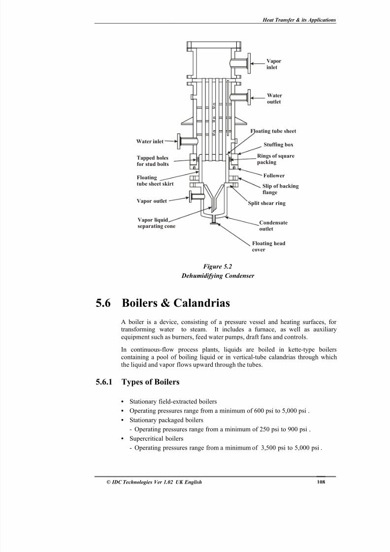
• Dehumidifying condensers ( Figure 5.2 )
8/6/2019 Heat Transfer & Its Applications
http://slidepdf.com/reader/full/heat-transfer-its-applications 10/15
Heat Transfer & its Applications
© IDC Technologies Ver 1.02 UK English 108
Vaporinlet
Wateroutlet
Floating tube sheet
Stuffing box
Rings of squarepacking
Follower
Slip of backing
flange
Split shear ring
Condensateoutlet
Floating headcover
Vapor liquidseparating cone
Vapor outlet
Floatingtube sheet skirt
Tapped holesfor stud bolts
Water inlet
Figure 5.2
Dehumidifying Condenser
5.6 Boilers & Calandrias
A boiler is a device, consisting of a pressure vessel and heating surfaces, for transforming water to steam. It includes a furnace, as well as auxiliary
equipment such as burners, feed water pumps, draft fans and controls.
In continuous-flow process plants, liquids are boiled in kette-type boilers
containing a pool of boiling liquid or in vertical-tube calandrias through which
the liquid and vapor flows upward through the tubes.
5.6.1 Types of Boilers
• Stationary field-extracted boilers
• Operating pressures range from a minimum of 600 psi to 5,000 psi .
• Stationary packaged boilers
- Operating pressures range from a minimum of 250 psi to 900 psi .
• Supercritical boilers
- Operating pressures range from a minimum of 3,500 psi to 5,000 psi .
8/6/2019 Heat Transfer & Its Applications
http://slidepdf.com/reader/full/heat-transfer-its-applications 11/15
Practical Fundamentals of Chemical Engineering
© IDC Technologies Ver 1.02 UK English 109
• Marine boilers
- Operating pressures range from a minimum of 900 psi to 1,200 psi .
• Waste heat boilers
- Operating pressure to a maximum limit of 800 psi .
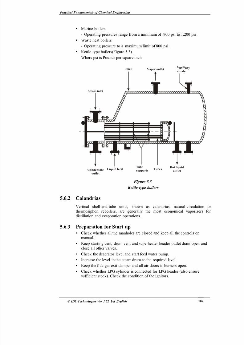
• Kettle-type boilers(Figure 5.3)
Where psi is Pounds per square inch
Steam inlet
Shell Vapor outlet ux arynozzle
Hot liquidoutlet
TubesTubesupports
Liquid feedCondensateoutlet
Figure 5.3 Kettle-type boilers
5.6.2 Calandrias
Vertical shell-and-tube units, known as calandrias, natural-circulation or thermosiphon reboilers, are generally the most economical vaporizers for
distillation and evaporation operations.
5.6.3 Preparation for Start up• Check whether all the manholes are closed and keep all the controls on
manual.
• Keep starting vent, drum vent and superheater header outlet drain open and
close all other valves.
• Check the deaerator level and start feed water pump.
• Increase the level in the steam drum to the required level
• Keep the flue gas exit damper and all air doors in burners open.
• Check whether LPG cylinder is connected for LPG header (also ensuresufficient stock). Check the condition of the ignitors.
8/6/2019 Heat Transfer & Its Applications
http://slidepdf.com/reader/full/heat-transfer-its-applications 12/15
Heat Transfer & its Applications
© IDC Technologies Ver 1.02 UK English 110
5.6.4 Routine Check-up During Normal Run• Check the drum level once in two hours and ensure whether both the level
transmitter readings match with direct level gauge glass.
• Check whether the air doors of all burners in service are fully opened
• Check the flame condition of burners regularly.
• Ensure that the Fuel oil (FO) isolation valves of all burners not in service are
closed
• Check all the oil drains for closed condition.
• Check the oil heater trap outlet for any leak.
• Check the pressure drop across suction and discharge oil filters.
• Check the FO tank temperature.
• Check the bearing temperature and lube oil level of FO pump, Boiler Feed
Water (BFW) pump and Forced Draft (FD) fan.
• Check the lube oil level, Rpm, regulating oil pressure and lube oil pressure of BFW, FD and FO turbines.
• Check the shaft movement in BFW pumps and pressure drop across suctionstrainer.
• Check the Deaerator level and check whether it matches direct level indicator.
• Check for any flue gas leak through Boiler ducts.
• Check for any leaks through pressure parts.
5.6.5 Shut Down
• After getting clearance from process plants to cut out steam supply, trip theBoiler from the control panel.
• Close the main stop valve, Continuous Blow Down (CBD), auxiliary steam
valve, sampling root valve and dosing valves.
• Increase the drum level to required value and stop the feed pump.
• Stop Heavy Fuel Oil (HFO) pump and dosing pumps.
• If a long shut-down is planned, ensure there is no fuel oil in the tank.
• Stop FD fan after 10 minutes and allow natural cooling of the Boiler
• Close all individual FO isolation valves and atomizing steam isolation valves.
• Remove all the guns for cleaning.
• Open all the trap bypasses.
• When the drum pressure reaches the required value, start vent.
• If a long shut-down is planned, ensure there is no fuel oil in the tank.
8/6/2019 Heat Transfer & Its Applications
http://slidepdf.com/reader/full/heat-transfer-its-applications 13/15
Practical Fundamentals of Chemical Engineering
© IDC Technologies Ver 1.02 UK English 111
5.7 Evaporators
The objective of evaporations is to concentrate a solution consisting of a
nonvolatile solute and a volatile solvent.
5.7.1 Types of EvaporatorsThe types of evaporators in use today are
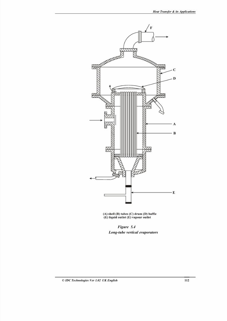
• Long-tube vertical evaporators ( Figure 5.4 )
- Upward flow (climbing-film)
- Downward flow (falling-film)
- Forced circulation
• Agitated-film evaporators
• Standard vertical short tube Evaporators (Calendria Type)
• Basket Evaporator
• External Calendria vertical tube Evaporators
• Horizontal tube Evaporators
• Forced circulation Evaporators
• Multiple effect Evaporator (Figure 5.5)
Upward flow (climbing-film) evaporator
The essential parts are
• A tubular exchanger with steam in the shell and liquid to be concentrated in
the tubes
• A separator or vapor space for removing entrained liquid from the vapour
• When operated as a circulation unit, a return leg for the liquid from the
separator to the bottom of the exchanger.
Inlets are provided for vapour ,thick liquor ,steam condensate and noncondensate
gases from the steam. Long tube vertical evaporators are especially effective inconcentrating liquids that tend to foam. This foam is ultimately broken when the
high-velocity mixture of liquid and vapour impinges against the vapour-head baffle.
8/6/2019 Heat Transfer & Its Applications
http://slidepdf.com/reader/full/heat-transfer-its-applications 14/15
Heat Transfer & its Applications
© IDC Technologies Ver 1.02 UK English 112
Figure 5.4
Long-tube vertical evaporators
8/6/2019 Heat Transfer & Its Applications
http://slidepdf.com/reader/full/heat-transfer-its-applications 15/15
Practical Fundamentals of Chemical Engineering
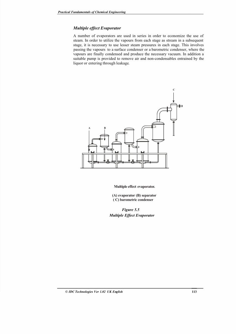
Multiple effect Evaporator
A number of evaporators are used in series in order to economize the use of steam. In order to utilize the vapours from each stage as stream in a subsequent
stage, it is necessary to use lesser steam pressures in each stage. This involves passing the vapours to a surface condenser or a barometric condenser, where thevapours are finally condensed and produce the necessary vacuum. In addition a
suitable pump is provided to remove air and non-condensables entrained by theliquor or entering through leakage.
A B
C
(A) evaporator (B) separator
( C) barometric condenser
Multiple effect evaporator.
Figure 5.5
Multiple Effect Evaporator